JVC KENWOOD 417101 900 MHz Digital Base Repeater User Manual
JVC KENWOOD Corporation 900 MHz Digital Base Repeater Users Manual
Contents
- 1. Users Manual
- 2. Users Manual RF Warning Page
Users Manual

NXR-900/ NXR-901
INSTRUCTION MANUAL
© B62-2410-00 (K)
09 08 07 06 05 04 03 02 01 00
MANUAL DE INSTRUCCTIONES
MODE D'EMPLOI
BASE-REPETIDOR DIGITAL 800MHz/ BASE-REPETIDOR DIGITAL 900MHz
800MHz DIGITAL BASE-REPEATER/ 900MHz DIGITAL BASE-REPEATER
BASE-RELAIS NUMÉRIQUE 800MHz/ BASE-RELAIS NUMÉRIQUE 900MHz
B
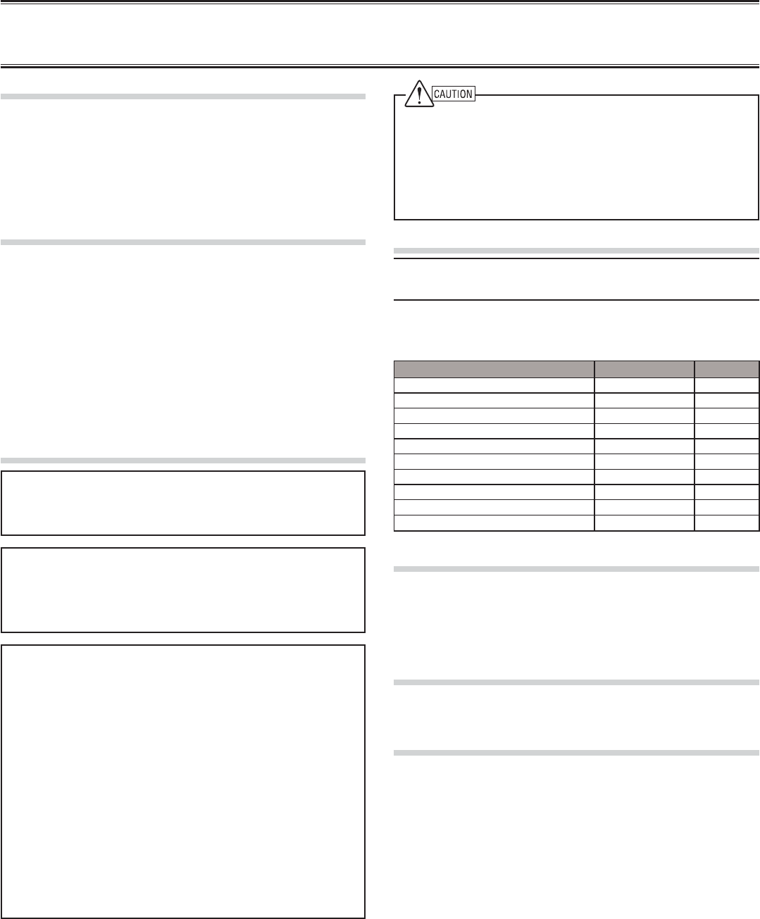
◆ This repeater is intended for use as a fixed base station with
the antenna located outdoors on the rooftop or on an antenna
tower. (except USA and Canada)
◆ This repeater is designed for a 13.8 V DC power source!
Never use a 24 V DC or higher source to power the repeater.
◆ Use only the supplied DC cord.
◆ Do not remove the ferrite core attached to the DC cord. Doing
so may cause interference with radio communications.
UNPACKING AND CHECKING EQUIPMENT
Note: The following unpacking information is for use by your
KENWOOD dealer, an authorized KENWOOD service center, or the
factory.
Carefully unpack the repeater. We recommend that you identify
the items listed in the following table before discarding the
packing material. If any items are missing or have been damaged
during shipment, file a claim with the carrier immediately.
Item Part Number Quantity
Front glass B10-2781-XX 1
Dressed screw N08-0563-XX 1
Bracket J29-0725-XX 2
Flat head machine screw N32-4008-XX 4
Handle and screw set K01-0421-XX 1
DC cord E30-3344-XX 1
Lead wire with connector (15 pin) E37-1381-XX 1
Fuse (7.5 A) F05-7521-XX 1
SYNC Cable E30-7701-XX 1
Instruction Manual B62-2410-XX 1
INSTALLATION
To install the handles onto the front panel of the repeater, align
the handles with the holes on the front panel, then secure the
handles using the supplied screws.
Please consult your dealer for installing the repeater and
antenna.
MICROPHONE
Connect an optional KMC-30, KMC-35, or KMC-9C KENWOOD
microphone to the MICROPHONE jack on the front panel.
OCXO UNIT (KXK-3):Option
The OCXO unit (KXK-3) is an Oven Controlled Crystal Oscillator
(OCXO) unit.
NOTICES TO THE USER
◆ Government law prohibits the operation of unlicensed radio
transmitters within the territories under government control.
◆ Illegal operation is punishable by fine and/or imprisonment.
◆ Refer service to qualified technicians only.
FCC WARNING
This equipment generates or uses radio frequency energy. Changes
or modifications to this equipment may cause harmful interference
unless the modifications are expressly approved in the instruction
manual. The user could lose the authority to operate this equipment if
an unauthorized change or modification is made.
INFORMATION TO THE DIGITAL DEVICE USER REQUIRED BY
THE FCC
This equipment has been tested and found to comply with the limits
for a Class B digital device, pursuant to Part 15 of the FCC Rules.
These limits are designed to provide reasonable protection against
harmful interference in a residential installation.
This equipment generates, uses and can generate radio frequency
energy and, if not installed and used in accordance with the
instructions, may cause harmful interference to radio communications.
However, there is no guarantee that the interference will not occur
in a particular installation. If this equipment does cause harmful
interference to radio or television reception, which can be determined
by turning the equipment off and on, the user is encouraged to try to
correct the interference by one or more of the following measures:
• Reorient or relocate the receiving antenna.
• Increase the separation between the equipment and receiver.
• Connect the equipment to an outlet on a circuit different from that to
which the receiver is connected.
• Consult the dealer for technical assistance.
THANK YOU!
We are grateful you purchased this KENWOOD repeater. We
believe this easy-to-program repeater will be highly effective in
your communications system, and will keep personnel operating
at peak efficiency.
KENWOOD incorporates the latest in advanced technology into
all of our products. As a result, we feel strongly that you will be
pleased with the quality and features of this product.
PRECAUTIONS
• Do not expose the unit to rain or moisture; to prevent fire or
electric shock.
• Do not open the unit under any circumstances; to avoid risk
of electric shock.
• Do not expose the unit to long periods of direct sunlight, nor
place it close to heating appliances.
• Do not place the unit in excessively dusty and/or humid
areas, nor on unstable surfaces.
• If you detect an abnormal odor or smoke coming from the
unit, disconnect the power from the unit immediately. Contact
your KENWOOD service center or dealer.
NXR-900/ NXR-901 INSTRUCTION MANUAL
800MHz DIGITAL BASE-REPEATER/ 900MHz DIGITAL BASE-REPEATER
C
REPEATER OPERATION
Note: Please consult your dealer for programming the repeater. Due
to the frequency stability on the 6.25 kHz bandwidth channel, when
operating the repeater using an optional OCXO unit, allow the unit to
warm up for 24 hours after turning the power on.
After turning on the power, wait for approximately 10 seconds for
the VCXO or 5 minutes for the OCXO (when mounting) to warm up.
During this time, the CH/STATUS Display will blink. The keys will
function when they are pressed.
When power is applied to the unit, the POWER indicator lights
green. Turn the VOLUME control clockwise until a click sounds,
to unmute the audio. Rotate to adjust the audio. Turn the
VOLUME control counterclockwise fully to mute the audio.
The BUSY indicator lights green while receiving a signal and the
TX indicator lights red while transmitting.
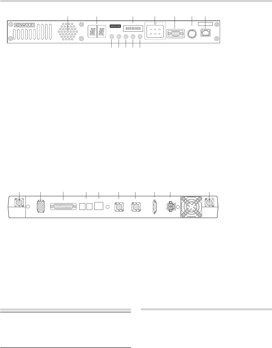
■ Rear Panel
q RX IN jack
Connect an RX antenna or a duplexer to this BNC
receptacle.
w TEST/SPKR jack
Test input/output jack. Connect an external speaker to
this jack.
e CONTROL I/O jack
Connect a repeater controller or a remote panel to this
DB-25 interface.
r SYNC 1 / 2 jack
Connect to another repeater to use synchronous frame
signaling for digital trunking.
t LAN jack
Connect to Ethernet.
CONTROLS AND FUNCTIONS
■ Front Panel qwrt
yu
io
e
qwrt y u
e
MICROPHONE
VOLUME
COM OFF/
POWERCTRL OCXO BUSY TX
12
MON
TAKE
OVER
RPT
DISABLE
ABC
345678
STATUS
TEST/SPKR
RX TX
CONTROL I/O SYNC
12 LAN REF OUT REF IN FUSE
75
DC 13.8V
y REF OUT jack
Connect to another repeater within the site to supply a
reference signal.
u REF IN jack
Connect from another repeater within the site to receive a
reference signal.
i FUSE
Insert 7.5 A blade fuse into this fuse holder.
o DC 13.8V jack
Connect a 13.8 V DC power supply to this jack.
!0 TX OUT jack
Connect a TX antenna or a duplexer to this BNC receptacle.
io!0
TRANSCEIVER OPERATION
■ Receive
Adjust the volume to your desired level. You may need to
readjust the volume if you are having interference while receiving
a message from your dispatcher or another member in your fleet.
The BUSY indicator lights green while a signal is being received.
■ Transmit
1 Listen to the channel before transmitting, to make sure it
is not being used.
2 Press the microphone PTT switch, then speak in your
normal speaking voice.
The TX indicator lights red while transmitting.
3 When you finish speaking, release the PTT switch.
!0
!1
!2
q Speaker
w CH/STATUS Display
Two 17-segment digits display the channel number, name,
or status.
e STATUS indicator
Indicates the status of the repeater. (NXDN mode)
r Programmable Function keys
Press these keys to activate their programmable
functions.
t COM jack
Connect to the PC using a RS-232C standard DB9
(Female) cross cable.
y VOLUME control
Turn clockwise until a click sounds, to unmute the audio.
Rotate to adjust the audio. Turn counterclockwise fully to
mute the audio.
u MICROPHONE jack
Connect a microphone to this 8-pin modular jack.
i POWER indicator
Lights green when power is supplied to the DC 13.8V
jack. Blinks red when an abnormal voltage is present.
While blinking, the repeater cannot be used.
o TX indicator
Lights red while transmitting.
!0 BUSY indicator
Lights green while a signal is being received.
!1 OCXO indicator
The OCXO indicator shows the state of the reference
10 MHz oscillator :
Lights Green when using a reference signal from an
optional OCXO unit (KXK-3).
Lights Orange when using a reference signal from another
repeater.
Lights red when no reference signal is available or when
an error occurs.
Does not light when the reference signal is an internal
VCXO signal.
!2 CTRL indicator
The CTRL indicator shows the control channel status
while using Digital trunking :
Lights Green when the repeater is used as control channel.
Blinks Green when using a non-dedicated control channel.

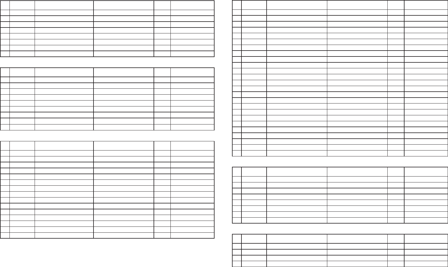
Addendum
Terminal Description
MIC (Modular Jack)
Pin
NO. Pin Name Description Specification I/O Notes
1 NC Not used Not used −
2 SB Power Output 13.8 V O
3 GND GND GND −
4 PTT PTT Signal Input Impedance 100 kΩ I
5 MICG MIC GND MIC GND −
6 MIC MIC Input 600 Ω I
7 HOOK Hook Detection Input Impeadance 100 kΩ I
8 NC Not used Not used −
COM (D-SUB 9 Pin) CONNECTOR
Pin
NO. Pin Name Description Specification I/O Notes
1 CD Carrier Detect Conform to RS-232C standard I
2 RD Receive Data Conform to RS-232C standard I
3 SD Send Data Conform to RS-232C standard O
4 DTR Data Terminal Ready Conform to RS-232C standard O
5 SG GND GND −
6 DSR Data Set Ready Conform to RS-232C standard I
7 RTS Request to Send Conform to RS-232C standard O
8 CTS Clear to Send Conform to RS-232C standard I
9 CI Ringer DET Conform to RS-232C standard I
TEST/ SPEAKER CONNECTOR
Pin
NO. Pin Name Description Specification I/O Notes
1 SB Power Output 13.8 V O
2 SB Power Output 13.8 V O
3 NC Not used Not used −
4 GND GND GND −
5 GND GND GND −
6 SPG Speaker GND Speaker GND −
7 RD RX Audio Output Load impedance 4.7 kΩ O not De-emphasis
8 RSSI RSSI Signal Output Output Level 0 to 5 V O
9 SPI Internal Speaker Input Short with "SPO" I
10 AO1 Open Collector Terminal Allowable current value MAX 200mA O
11 AO2 Open Collector Terminal Allowable current value MAX 200mA O
12 SPO External Speaker Output Output Level 3W (5%Distortion) O
13 AO3 Open Collector Terminal Allowable current value MAX 200mA O
14 AO4 Open Collector Terminal Allowable current value MAX 200mA O
15 AO5 Open Collector Terminal Allowable current value MAX 200mA O
Control I/O (D-SUB 25 Pin) CONNECTOR
Pin
NO. Pin Name Description Specification I/O Notes
1 NC Not used Not used −
2 NC Not used Not used −
3 NC Not used Not used −
4 AI1 Programmable Function Input 1 Input Impedance 47 kΩ I
5 AI2 Programmable Function Input 2 Input Impedance 47 kΩ I
6 AI3 Programmable Function Input 3 Input Impedance 47 kΩ I
7 DG Digital GND Digital GND −
8 TD TX Audio Input Input Impedance 600 Ω I not Pre-emphasis
9 TA TX Audio Input Input Impedance 600 Ω I Pre-emphasis
10 RD RX Audio Output Load Impedance 4.7 kΩ O not De-emphasis
11 RA RX Audio Output Load Impedance 4.7 kΩ O De-emphasis
12 RXG RX Signal GND RX Signal GND −
13 SPM Speaker Mute Input Impedance 47 kΩ I
14 BER CLK For Bit Error Rate Clock CMOS O
15 EMON External Monitor Switch Input Impedance 47 kΩ I
16 EPTT External PTT Switch Input Impedance 47 kΩ I
17 SC Squelch Control Output level 0 or 3.3 V O
18 BER DAT For Bit Error Rate Data CMOS O
19 TXG TX Signal GND TX Signal GND −
20 IO1 Programmable Function I/O 1 Input Impedance 47 kΩ I/O Output level 0 or 5 V
21 IO2 Programmable Function I/O 2 Input Impedance 47 kΩ I/O Output level 0 or 5 V
22 IO3 Programmable Function I/O 3 Input Impedance 47 kΩ I/O Output level 0 or 5 V
23 IO4 Programmable Function I/O 4 Input Impedance 47 kΩ I/O Output level 0 or 5 V
24 IO5 Programmable Function I/O 5 Input Impedance 47 kΩ I/O Output level 0 or 5 V
25 IO6 Programmable Function I/O 6 Input Impedance 47 kΩ I/O Output level 0 or 5 V
LAN (Modular Jack)
Pin
NO. Pin Name Description Specification I/O Notes
1 TD+ TX Signal + Comform to IEEE802.3 standard O 100 Mbps
2 TD- TX Signal − Comform to IEEE802.3 standard O 100 Mbps
3 RD+ RX Signal + Use Designated Transformer I 100 Mbps
4 NC Not used Not used −
5 NC Not used Not used −
6 RD- RX Signal − Use Designated Transformer I 100 Mbps
7 NC Not used Not used −
8 NC Not used Not used −
SYNC 1, 2 Connector (There are two connectors)
Pin
NO. Pin Name Description Specification I/O Notes
1 FRMA RS-485 Differential Signal A Conform to RS485 I/O
2 NC Not used Not used −
3 NC Not used Not used −
4 FRMB RS-485 Differential Signal B Conform to RS485 I/O
RX ANT Impedance 50 Ω
TX ANT Impedance 50 Ω
REF IN External Reference Signal Input (10 MHz). Impedance : more than 1 kΩ
REF OUT Reference Signal Distribution (10 MHz). Load Impedance : more than 20 Ω
B59-2539-00
MANDATORY SAFETY INSTRUCTIONS TO INSTALLERS AND USERS
• Use only manufacturer or dealer supplied antennas.
• Antenna Minimum Safe Distance: 30 cm (1 foot).
• Antenna Gain: 0 dBd referenced to a dipole.
The Federal Communications Commission has adopted a safety standard for
human exposure to RF (Radio Frequency) energy which is below the OSHA
(Occupational Safety and Health Act) limits.
• Antenna Mounting: The antenna supplied by the manufacturer or radio dealer
must not be mounted at a location such that during radio transmission, any
person or persons can come closer than the above indicated minimum safe
distance to the antenna, i.e. 30 cm (1 foot).
• To comply with current FCC RF Exposure limits, the antenna must be installed
at or exceeding the minimum safe distance shown above, and in accordance
with the requirements of the antenna manufacturer or supplier.
• Vehicle installation: The antenna can be mounted at the center of a vehicle
metal roof or trunk lid, if the minimum safe distance is observed.
• Base Station Installation: The antenna should be xed-mounted on an outdoor
permanent structure. RF Exposure compliance must be addressed at the time
of installation.
Antenna substitution: Do not substitute any antenna for the one supplied or
recommended by the manufacturer or radio dealer.
You may be exposing person or persons to excess radio frequency radiation. You
may contact your radio dealer or the manufacturer for further instructions.
Maintain a separation distance from the antenna to person(s) of at least 30 cm (1 foot).
You, as the qualied end-user of this radio device must control the exposure
conditions of bystanders to ensure the minimum separation distance (above) is
maintained between the antenna and nearby persons for satisfying RF Exposure
compliance. The operation of this transmitter must satisfy the requirements of
Occupational/Controlled Exposure Environment, for work-related use, transmit
only when person(s) are at least the minimum distance from the properly installed,
externally mounted antenna. Transmit only when people outside the vehicle
are at least the recommended minimum lateral distance away from the antenna/
vehicle.
B59-xxxx-00