JVC KENWOOD 431200 UHF Digital Transceiver User Manual Instruction Manual
JVC KENWOOD Corporation UHF Digital Transceiver Instruction Manual
UserManual.wiki
>
JVC KENWOOD
>
431200 User Manual
Instruction Manual
Navigation menu
Upload a User Manual
Namespaces
Wiki Guide
HTML
PDF
Info
Views
User Manual
Discussion / Help
Navigation
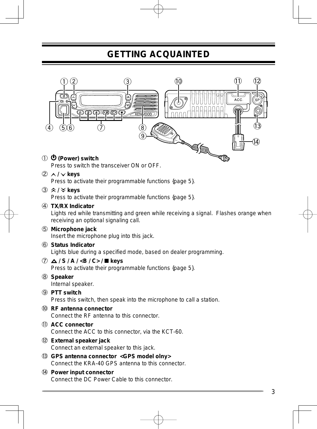
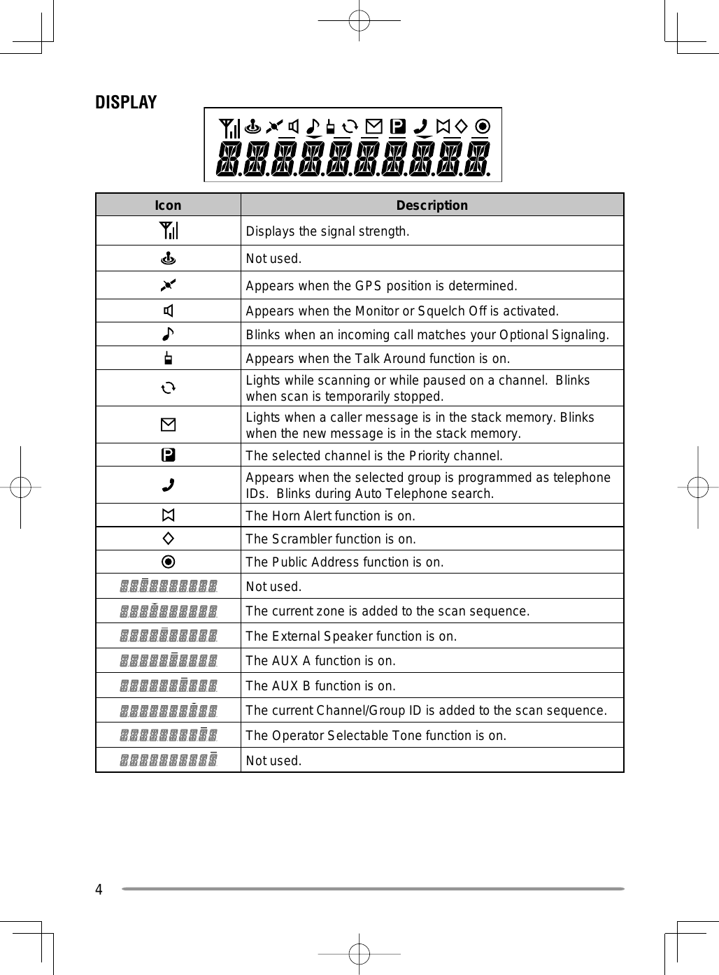
![61 Available only for Analog Trunking operation.2 Available only for NXDN Trunking operation.3 Available only for NXDN Conventional operation.4 Emergency can be programmed only on the key. When assigned, the dealer must set the key assignment hold to “Enable” and second function as “Emergency”.5 Available only for NXDN Conventional operation and NXDN Trunking operation.6 Available only for Analog Conventional, Analog Trunking, and NXDN Conventional operation.7 Available only for Analog Conventional operation.8 Available only for Analog Conventional and NXDN Conventional operation.9 Available only for Analog Conventional and Analog Trunking operation.BASIC OPERATIONSSWITCHING POWER ON/ OFFPress to switch the transceiver ON.• A beep sounds and the display illuminates.• If the Transceiver Password function is programmed, “PASSWORD” will appear on the display.Press again to switch the transceiver OFF.■ Transceiver Password To enter the password:1 Press the / key to select a digit.• When using a keypad, simply enter the password digits and proceed to step 4.2 Press the S or key to accept the entry and move to the next digit.• Press the A or # key to delete an incorrect digit.• Press the C> key to delete all.3 Repeat steps 1 and 2 to enter the entire password.• The password can contain a maximum of 6 digits.4 Press the S or key to confirm the entered password.• If you enter an incorrect password, an error tone sounds and the transceiver remains locked.ADJUSTING THE VOLUMEPress the [Volume Up] key to increase the volume. Press the [Volume Down] key to decrease the volume.If Squelch Off has been programmed onto a key, you can use that function to listen to background noise while adjusting the volume level.](https://usermanual.wiki/JVC-KENWOOD/431200/User-Guide-1788475-Page-11.png)
![7SELECTING A ZONE AND CHANNEL/GROUP IDSelect the desired zone and channel/group ID using the keys programmed as [Zone Up]/ [Zone Down] and [CH/GID Up]/ [CH/GID Down].• You can program names for zones and channels/group IDs with up to 10 characters.TRANSMITTING/ RECEIVING1 Select the desired zone and channel/group ID.2 Press the key programmed as [Monitor] or [Squelch Off] to check whether or not the channel is free.• If the channel is busy, wait until it becomes free.3 Press the PTT switch and speak into the microphone. Release the PTT switch to receive.• For best sound quality, hold the transceiver approximately 1.5 inches (3 ~ 4 cm) from your mouth.■ Making Group Calls (Digital) If a key has been programmed as [Group], you can select a group ID from the list to make a call to those parties on a Conventional channel. To select a group ID:1 Press the key programmed as [Group].2 Press the / key to select a group ID/name from the list.3 Press and hold the PTT switch to make the call.• Speak into the transceiver as you would during a normal transmission.■ Making Individual Calls (Digital) (Types I and II Only) If a key has been programmed with [Individual], you can make calls to specific persons.1 Press the key programmed as [Individual].2 Press the / key to select a unit ID from the list.• On Type I models, you can enter a unit ID directly.3 Press and hold the PTT switch to make the call.• Speak into the transceiver as you would during a normal transmission.](https://usermanual.wiki/JVC-KENWOOD/431200/User-Guide-1788475-Page-12.png)
![8RECEIVINGSelect the desired zone and channel. If signaling has been programmed on the selected channel, you will hear a call only if the received signal matches your transceiver settings.Note: Signaling allows your transceiver to code your calls. This will prevent you from listening to unwanted calls. Refer to “SIGNALING” on page XX for details. ■ Receiving Group Calls (Digital) When you receive a group call on a Conventional channel and the received group ID matches the ID set up on your transceiver, you can hear the caller’s voice. When you receive a group call on a Trunking channel, the transceiver automatically switches to the communications channel to receive the call.■ Receiving Individual Calls (Digital) When you receive an individual call, a ringing tone will sound and the caller’s ID will appear on the display (types I and II only). To respond to the call, press and hold the PTT switch and speak into the transceiver as you would during a normal transmission.SCANScan monitors for signals on the transceiver channels. While scanning, the transceiver checks for a signal on each channel and only stops if a signal is present.To begin scanning, press the key programmed as [Scan].• The indicator appears.• When a signal is detected on a channel, Scan pauses at that channel. The transceiver will remain on the busy channel until the signal is no longer present, at which time Scan resumes.To stop scanning, press the [Scan] key again.Note: To use Scan, there must be at least 2 channels in the scan sequence.TEMPORARY CHANNEL LOCKOUTDuring scan, you can temporarily remove specific channels from the scanning sequence by selecting them and pressing the key programmed as [Scan Delete/Add].• The channel is no longer scanned. However, when scanning is ended and restarted, the channels are reset and deleted channels will again be in the scanning sequence.PRIORITY SCANIf a Priority channel has been programmed, the transceiver will automatically change to the Priority channel when a call is received on that channel, even if a call is being received on a normal channel.• The indicator appears when the selected channel is the Priority channel (depending on dealer setting).](https://usermanual.wiki/JVC-KENWOOD/431200/User-Guide-1788475-Page-13.png)
![9SCAN REVERTThe Scan Revert channel is the channel selected when you press the PTT switch to transmit during scan. Your dealer can program one of the following types of Scan Revert channels:• Selected: The last channel selected before scan.• Selected + Talkback: Same as “Selected”, plus you can respond to calls on the channel at which scan is paused.• Priority: The Priority channel.• Priority + Talkback: Same as “Priority”, plus you can respond to calls on the channel at which scan is paused.• Last Called + Selected: The last channel on which you receive a call.SCAN DELETE/ADDYou can add and remove zones and/or channels/group IDs to and from your scan list.1 Select your desired zone and/or channel/group ID.2 Press the key programmed as [Zone Delete/Add] (to add/remove zones) or [Scan Delete/Add] (to add/remove channels/group IDs).• You can also press and hold the key programmed as [Scan Delete/Add] to add/remove zones.• When a channel/Group ID is added to scan, the icon appears on the display.• When a zone is added to scan, the icon appears on the display.](https://usermanual.wiki/JVC-KENWOOD/431200/User-Guide-1788475-Page-14.png)
![10FleetSync: ALPHANUMERIC 2-WAY PAGING FUNCTIONFleetSync is an Alphanumeric 2-way Paging Function, and is a protocol owned by JVC KENWOOD Corporation.Note: This function is available only in analog operation.SELCALL (SELECTIVE CALLING)A Selcall is a voice call to a station or group of stations.■ Transmitting1 Select your desired zone and channel.2 Press the key programmed as [Selcall] to enter Selcall mode.3 Press the / key to select the station you want to call.4 Press the PTT switch and begin your conversation.■ Receiving An alert tone will sound and the transceiver will enter Selcall mode. The calling station’s ID will appear when a Selcall is received (types I and II only). You can respond to the call by pressing the PTT switch and speaking into the microphone.■ Identifi cation Codes An ID code is a combination of a 3-digit Fleet number and a 4-digit ID number. Each transceiver has its own ID.• Enter a Fleet number (100 ~ 349) to make a group call.• Enter an ID number (1000 ~ 4999) to make an individual call in your fleet.• Enter a Fleet number to make a call to all units in the selected fleet (Fleet call).STATUS MESSAGEYou can send and receive 2-digit Status messages which may be decided in your talk group. Messages can contain up to 16 alphanumeric characters. Status messages range from 10 to 99 (80 ~ 99 are reserved for special messages).A maximum of 15 received messages (combined status messages and short messages) can be stored in the stack memory of your transceiver.■ Transmitting1 Select your desired zone and channel.2 Press the key programmed as [Status] to enter Status mode (proceed to step 5) or [Selcall + Status] to enter Selcall mode (proceed to step 3).3 Press the / key to select the station you want to call.• If Manual Dialing is enabled, you can enter a station ID by using the DTMF keypad by pressing and hold the S or key. Repeat this process until the entire ID is entered.](https://usermanual.wiki/JVC-KENWOOD/431200/User-Guide-1788475-Page-15.png)
![114 Press the S or key to enter Status mode.5 Press the / key to select the status you want to transmit.• If Manual Dialing is enabled, you can enter a station ID by using the DTMF keypad. (refer to step 3, above).6 Press the PTT switch or Side 2 key to initiate the call.• “COMPLETE” appears on the display when the status has been successfully transmitted.■ Receiving A calling ID or text message will appear when a Status call is received. Press any key to return to normal operation.■ Reviewing Messages in the Stack Memory1 Press the key programmed as [Stack], or press and hold the key programmed as [Selcall], [Status], or [Selcall + Status] to enter Stack mode.• The last received message is displayed.2 Press the / key to select the desired message.• Message types are identified as follows: ID: Caller ID, ST: Status Message, ME: Short Message• Press and hold the S key for 1 second to cycle the display information as follows: ID Name > Status/Short Message > CH/GID 3 Press the Side 1 key to return to normal operation.• To delete the selected message, press the A key. To confirm the deletion, Press the S key.• To delete all messages, press and hold the A or # key for 1 second. To confirm the deletion, Press the S or key.SHORT MESSAGESThis transceiver can receive short data messages which contain a maximum of 48 characters.• Received short messages are displayed the same as Status messages. A maximum of 15 received messages (combined status messages and short messages) can be stored in the stack memory of your transceiver.GPS REPORTTo send your location data, you must first connect a GPS unit to the transceiver. GPS data can be manually transmitted by pressing the key programmed as [Send the GPS data]. If set up by your dealer, GPS data may be automatically transmitted at a preset time interval.](https://usermanual.wiki/JVC-KENWOOD/431200/User-Guide-1788475-Page-16.png)
![12TRUNKING CALLS (ANALOG)PLACING A DISPATCH CALL1 Select the desired zone and channel/group ID.2 Press and hold the PTT switch.3 If the “PTT Proceed” tone sounds, communication is possible; start speaking into the microphone. Release the PTT switch to receive.• For best sound quality at the receiving station, hold the microphone approximately 1.5 inches (3 ~ 4 cm) from your mouth.• Your dealer can deactivate the Proceed PTT tone, if necessary. Ask your dealer for details.RECEIVING A DISPATCH CALL1 When a dispatch call is received, the transceiver will automatically change to the correct group ID and you will hear the call.2 Readjust the volume as necessary.PLACING A TELEPHONE CALL1 Select the desired zone and channel/group ID.2 Press and hold the PTT switch for approximately 1 second to ensure a connection.• Confirm that there is a dial tone after releasing the PTT switch. 3 Alternatively, press the key programmed as [Auto Telephone] to automatically search for a Telephone Repeater.• “AUTO TEL” appears on the display and the icon blinks.• When the transceiver connects to a telephone line, a dial tone sounds, the icon appears on the display, and the transceiver enters the Off Hook state. 4 Place the call, following the instructions for making a DTMF call, starting on page 9.5 When the called party responds, press the PTT switch and speak into the microphone. Release the PTT switch to receive.• Only one person can speak at a time.RECEIVING A TELEPHONE CALL1 When a telephone call is received, the transceiver will automatically change to the correct group ID and you will hear the call.• A ringer tone will sound when a call is received.2 Press and hold the PTT switch to speak, and release it to receive.• Only one person can speak at a time.DISCONNECT WITH TELEPHONETo end the call, press the # key or the key programmed as [Telephone Disconnect] while communicating.](https://usermanual.wiki/JVC-KENWOOD/431200/User-Guide-1788475-Page-17.png)
![13ADVANCED OPERATIONSDTMF (DUAL TONE MULTI FREQUENCY) CALLS ■ Making a DTMF Call Manual Dialing1 Press and hold the PTT switch.2 Enter the desired digits using the DTMF keypad.• If you release the PTT switch, transmit mode will end even if the complete number has not been sent.• If the Keypad Auto PTT function has been enabled by your dealer, you do not need to press the PTT switch to transmit; you can make the call simply by pressing the DTMF keys. Store & Send1 Press the key programmed as [Autodial].2 Enter up to 30 digits using the DTMF keypad.• Alternatively, you can enter digits by using the Selector.3 Press the PTT switch to make the call.■ Autodial Autodial allows you to quickly call DTMF numbers that have been programmed onto your transceiver.1 Press the key programmed as [Autodial].• The first entry in the Autodial list appears on the display.2 Press the / key to select your desired Autodial list number, or enter the list number directly (01 ~ 32).• The stored entry appears on the display.3 Press the PTT switch to make the call.■ Stun Code This function is used when a transceiver is stolen or lost. When the transceiver receives a call containing a stun code, the transceiver becomes disabled. The stun code is cancelled when the transceiver receives a call with a revive code.](https://usermanual.wiki/JVC-KENWOOD/431200/User-Guide-1788475-Page-18.png)
![14EMERGENCY CALLSIf your transceiver has been programmed with the Emergency function, you can make emergency calls.1 Press and hold the key programmed as [Emergency].• Ask your dealer for the length of time necessary to hold this key before the transceiver enters Emergency mode.• When the transceiver enters Emergency mode, it will change to the Emergency channel and begin transmitting based on how it is set up by your dealer.2 To exit Emergency mode, press the [Emergency] key again.• If the Emergency mode completes a preset number of cycles, Emergency mode will automatically end and the transceiver will return to the zone and channel that was in use before Emergency mode was entered.Note:◆ Your dealer can set the transceiver to emit a tone when transmitting in Emergency mode.◆ Your dealer can set the transceiver to emit tones and received signals as normal, or mute the speaker during Emergency operation.SCRAMBLERPress the key programmed as [Scrambler/ Encryption], to switch the transceiver to secure (encrypted) transmission.• Pressing the PTT switch after the Scrambler function has been turned ON encrypts the transmitted signal.SIGNALING■ Quiet Talk (QT)/ Digital Quiet Talk (DQT) Your dealer may have programmed QT or DQT signaling on your transceiver channels. A QT tone/ DQT code is a sub-audible tone/code which allows you to ignore (not hear) calls from other parties who are using the same channel. Operator Selectable Tone If a key has been programmed with [OST], you can reprogram the QT/DQT settings on each of your channels.1 Select your desired channel.2 Press and hold the key programmed as [OST] for 1 second.3 Press the / key to select your desired tone or code.• Your dealer can set up to 40 tones/codes.4 When you have finished operating using OST, press the [OST] key again to turn the OST function OFF.](https://usermanual.wiki/JVC-KENWOOD/431200/User-Guide-1788475-Page-19.png)
![15■ Radio Access Number (RAN) RAN is a new signaling system designed for digital radio communications. When a channel is set up with a RAN, squelch will only open when a call containing a matching RAN is received. If a call containing a different RAN is made on the same channel you are using, you will not hear the call. This allows you to ignore (not hear) calls from other parties who are using the same channel.■ Optional Signaling Your dealer may also program several types of optional signaling for your transceiver channels. 2-tone Signaling: 2-tone Signaling opens the squelch only when your transceiver receives a call containing matching 2 tones. DTMF Signaling: DTMF Signaling opens the squelch only when the transceiver receives a call containing a matching DTMF code. FleetSync Signaling: Refer to “SELCALL (SELECTIVE CALLING)” on page XX. NXDN ID Signaling: NXDN ID is an optional signaling system available only for digital communications.MONITOR/ SQUELCH OFFYou can use the key programmed as [Monitor] or [Squelch Off] to listen to weak signals that you cannot hear during normal operation and to adjust the volume when no signals are present on your selected channel.• The icon appears on the display while Monitor or Squelch Off is activated.Your dealer can program a key with one of four Monitor/Squelch Off functions:• Monitor: Press to deactivate QT, DQT, DTMF, 2-tone, or FleetSync Signaling. Press again to return to normal operation.• Monitor Momentary: Press and hold to deactivate QT, DQT, DTMF, 2-tone or FleetSync Signaling. Release to return to normal operation.• Squelch Off: Press to hear background noise. Press again to return to normal operation.• Squelch Off Momentary: Press and hold to hear background noise. Release to return to normal operation.■ Squelch Level If a key has been programmed as [Squelch Level], you can readjust your transceiver’s squelch level:1 Press the key programmed as [Squelch Level].• The icon appears on the display, along with the current squelch level.2 Press the / key to select your desired squelch level from 0 to 9.3 Press the C> key to store the new setting.](https://usermanual.wiki/JVC-KENWOOD/431200/User-Guide-1788475-Page-20.png)
![16SIGNAL STRENGTH INDICATORThe signal strength indicator displays the strength of received calls. No icon appears when no signal is available.Strong Sufficient Weak Very weak flashes when out of range (NXDN Trunking only).PUBLIC ADDRESS (PA)The PA system can only be used with an external speaker.1 Press the key programmed as [Public Address] to activate the Public Address function.• The icon appears on the display.2 Press and hold the PTT switch, then speak into the microphone to make your address through the external speaker.3 Press the [Public Address] key again to exit Public Address.HORN ALERTPress the key programmed as [Horn Alert] to toggle the Horn Alert function ON or OFF.• The icon appears on the display while Horn Alert is activated.EXTERNAL SPEAKERAfter attaching an external speaker to the transceiver, press the key programmed as [External Speaker] to output all received signals through the external speaker.• The icon appears on the display.Press the [External Speaker] key again to output all received signals only through the built-in speaker.DISPLAY BRIGHTNESSYou can cycle the display brightness between high, low, and off by pressing the key programmed as [LCD Brightness].](https://usermanual.wiki/JVC-KENWOOD/431200/User-Guide-1788475-Page-21.png)
![17BACKGROUND OPERATIONSTIME-OUT TIMER (TOT) The Time-out Timer prevents you from using a channel for an extended duration. If you continuously transmit for a preset time, the transceiver will stop transmitting and an alert tone will sound. Release the PTT switch.AUXILIARY PORTPress the key programmed as [AUX A] or [AUX B] to activate the auxiliary port. The auxiliary port is used with optional boards.• The icon appears on the display when the auxiliary A port is active.• The icon appears on the display when the auxiliary B port is active.BUSY CHANNEL LOCKOUT (BCL)If BCL is set up by your dealer, you will be unable to transmit if the channel is already in use.• “BUSY” appears on the display when you press the PTT switch. Use a different channel or wait until the channel becomes free.If your dealer has programmed BCL Override for your transceiver, you can override the BCL by pressing the PTT switch again, immediately after releasing it, when the channel is busy.CONTROL CHANNEL HUNTOn digital Trunking channels, the transceiver automatically searches for a control channel.• While searching for a control channel, the antenna icon will flash (types I and II only) and no signals can be received.PTT IDPTT ID is the transceiver unique ID code which is sent each time the PTT switch is pressed and/or released.COMPANDERIf programmed by your dealer for a channel, the compander will remove excessive noise from transmitted signals, providing higher clarity of signals.TRANSMIT POWERYour dealer has programmed a transmit power level for each channel. Power levels can be high, medium, or low.](https://usermanual.wiki/JVC-KENWOOD/431200/User-Guide-1788475-Page-22.png)