JVC KENWOOD 452600 VHF Digital Transceiver User Manual
JVC KENWOOD Corporation VHF Digital Transceiver
UserManual.wiki
>
JVC KENWOOD
>
452600 User Manual
User Manual
Navigation menu
Upload a User Manual
Namespaces
Wiki Guide
HTML
PDF
Info
Views
User Manual
Discussion / Help
Navigation

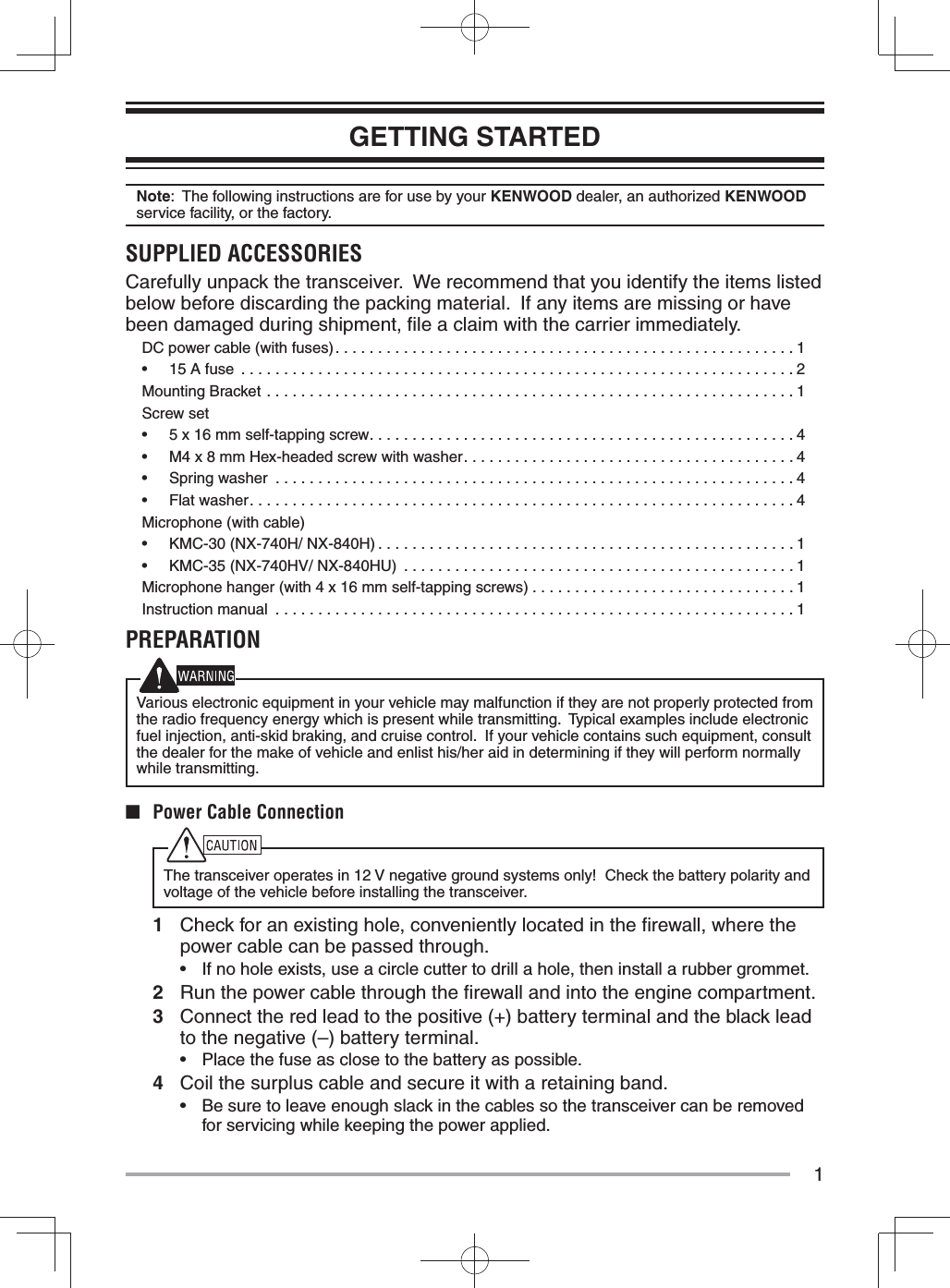
![5BASIC OPERATIONSSWITCHING POWER ON/ OFFPress to switch the transceiver ON.• A beep sounds and the display illuminates.• If the Transceiver Password function is programmed, “PS” will appear on the display when the power is turned ON. Refer to “Transceiver Password”, below.Press again to switch the transceiver OFF.■ Transceiver Password To enter the password:1 Press / to select a digit.• When using an optional microphone with a DTMF keypad, simply enter the password digits and proceed to step 3.2 Press C> to accept the entered digit and move to the next digit.• Press A or # to delete an incorrect digit. Press and hold A or # to delete all digits.• Repeat steps 1 and 2 to enter the entire password.3 Press S or to confi rm the password.• If you enter an incorrect password, the transceiver remains locked.ADJUSTING THE VOLUMEPress the [Volume Up] key to increase the volume. Press the [Volume Down] key to decrease the volume.If Squelch Off has been programmed onto a key, you can use that function to listen to background noise while adjusting the volume level.SELECTING A ZONE AND CHANNELSelect the desired zone and channel using the keys programmed as [Zone Up]/[Zone Down] and [Channel Up]/ [Channel Down].• “G1” (Zone 1) appears on the display.TRANSMITTING1 Select your desired zone and channel.2 Press the key programmed as [Monitor] or [Squelch Off] to check whether or not the channel is free.• If the channel is busy, wait until it becomes free.3 Press the PTT switch and speak into the microphone to transmit. Release the PTT switch to receive.• For best sound quality at the receiving station, hold the microphone approximately 1.5 inches (3 ~ 4 cm) from your mouth.RECEIVINGSelect the desired zone and channel. If signaling has been programmed on the selected channel, you will hear a call only if the received signal matches your transceiver settings.Note: Signaling allows your transceiver to code your calls. This will prevent you from listening to unwanted calls. Refer to “SIGNALING” on page 8 for details.](https://usermanual.wiki/JVC-KENWOOD/452600/User-Guide-2180760-Page-9.png)
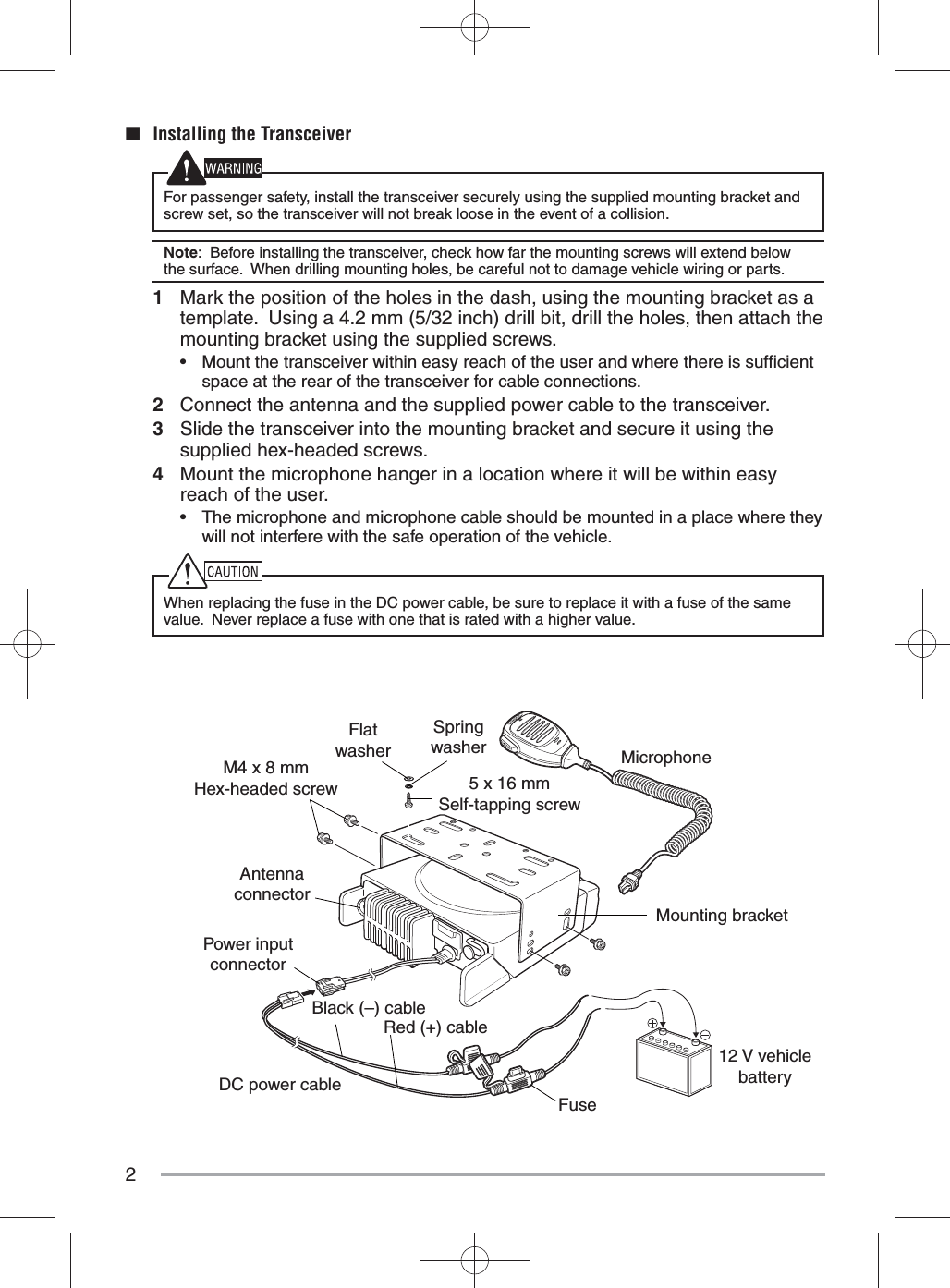
![6NXDNNXDN is a general term for the NXDN wireless communication protocol which uses 4 Level FSK. Various data communications, including individual and group voice communications, Status calls, and GPS data transmission, are possible.INDIVIDUAL/ GROUP CALLSEach channel is set up with an individual or group ID list number. To make a call, select the channel with the ID list number you wish to call, then press the PTT switch to start the call.• Your dealer may also have set Selcall on PTT for Individual or Group calls, allowing you to make an Individual or Group call when pressing the PTT switch.• To page the target transceiver instead of initiating a voice call, press the key programmed as [Paging Call].• If PTT Proceed tone is enabled, the Proceed tone will sound. After the tone ends, you can being the call.■ Receiving When you receive an individual call, a ringing tone will sound. Respond to the call by pressing the PTT switch.• If the auto reset timer expires before you respond to the call, the call will end. Your dealer can set the duration for the auto reset timer (default is 10 seconds). When you receive a group call and the received group ID matches the ID set up on your transceiver, a ringing tone will sound and you can hear the caller’s voice.STATUS CALLYou can transmit your status (preset by your dealer) to the target transceiver by pressing the key programmed as [Call 1] or [Call 2], if they have been set up with an NXDN Status.• Channels are set up with ID list numbers by your dealer. Select the desired channel before sending the status call.SCANScan monitors for signals on the transceiver channels. While scanning, the transceiver checks for a signal on each channel and only stops if a matching signal is present.To start/ stop scanning, press the key programmed as [Scan].• “Sc” appears on the display during Scan.• When a signal is detected, Scan pauses at that channel. The transceiver will remain on the busy channel until the signal is no longer present, at which time Scan resumes. Note: To use Scan, there must be at least 2 channels added to the scanning sequence.](https://usermanual.wiki/JVC-KENWOOD/452600/User-Guide-2180760-Page-10.png)
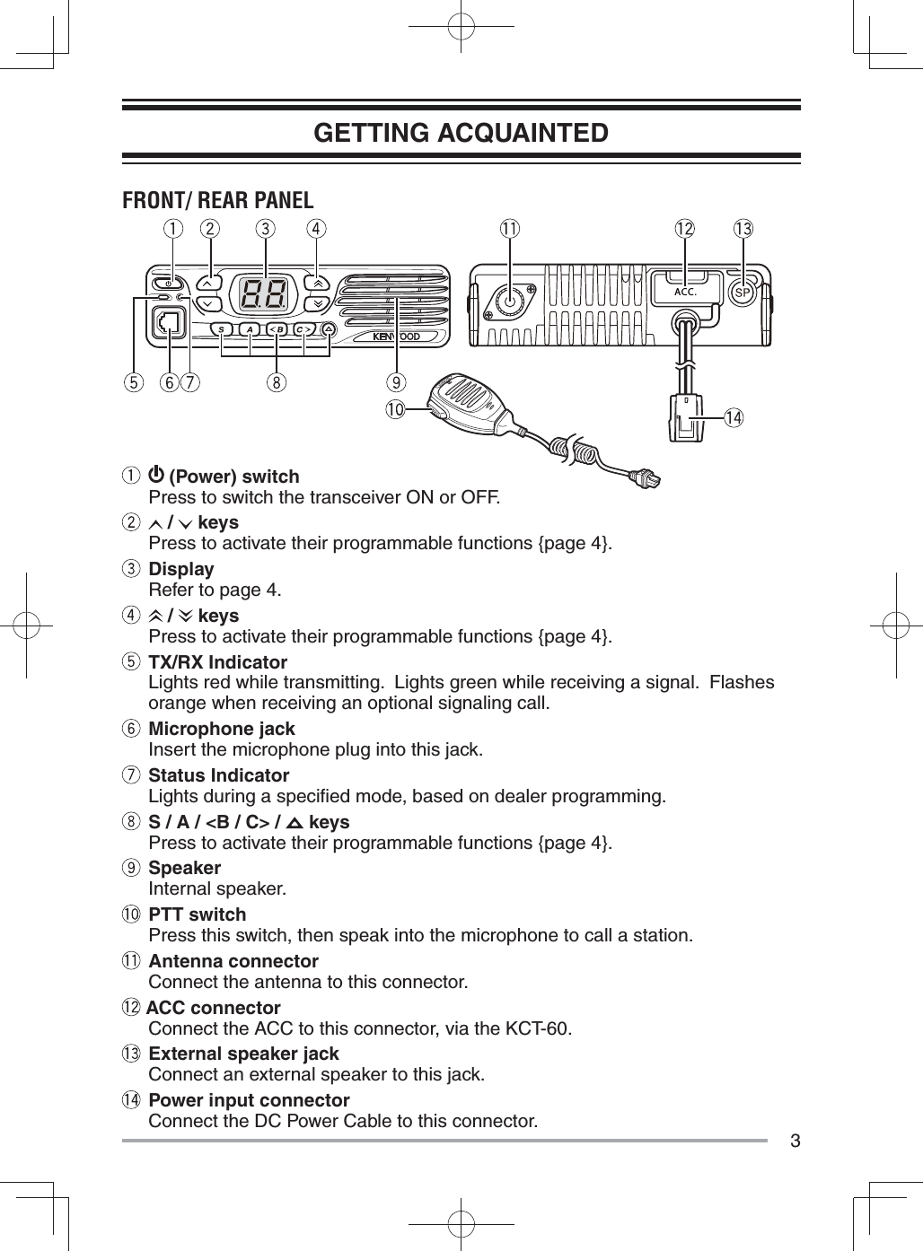
![7PRIORITY SCANIf a Priority channel has been programmed, the transceiver will automatically change to the Priority channel when a call is received on that channel, even if call is being received on a normal channel.• “P” appears on the display to indicate the Priority channel (depending on dealer setting).TEMPORARY CHANNEL LOCKOUTDuring scan, you can temporarily remove specifi c channels from the scanning sequence by pressing the key programmed as [Scan Delete/Add] while Scan is paused at the undesired channel. • The channel/ zone is no longer scanned. However, when scanning is ended and restarted, the Scan settings return to normal.SCAN DELETE/ ADDYou can add and remove channels to and from your scan list.1 Select your desired channel.2 Press the key programmed as [Scan Delete/Add] to remove a channel.• When a channel is added to scan, “cA” appears on the display. When it is removed, “cd” appears on the display.DTMF CALLSNote: To make DTMF calls, you must use an optional microphone with a DTMF keypad.MANUAL DIALING1 Press and hold the PTT switch.2 Enter the desired digits using the keypad.• If Keypad Auto-PTT is enabled by your dealer, you do not need to press the PTT switch to transmit; you can make the call simply by pressing the keys.AUTODIALAutodial allows you to quickly call DTMF numbers that have been programmed onto your transceiver.1 Press the key programmed as [Autodial] or the key.• “Ad” appears on the display.2 Enter the desired memory location number (1 ~ 9).3 Press the PTT switch to make the call.REDIALING1 Press the key programmed as [Autodial] or the key.• “Ad” appears on the display.2 Press the 0 key.• “rd” appears on the display.• If there is no data in the redial memory, an error tone will sound.3 Press the PTT switch to make the call.Note: Switching the transceiver power OFF clears the redial memory.](https://usermanual.wiki/JVC-KENWOOD/452600/User-Guide-2180760-Page-11.png)
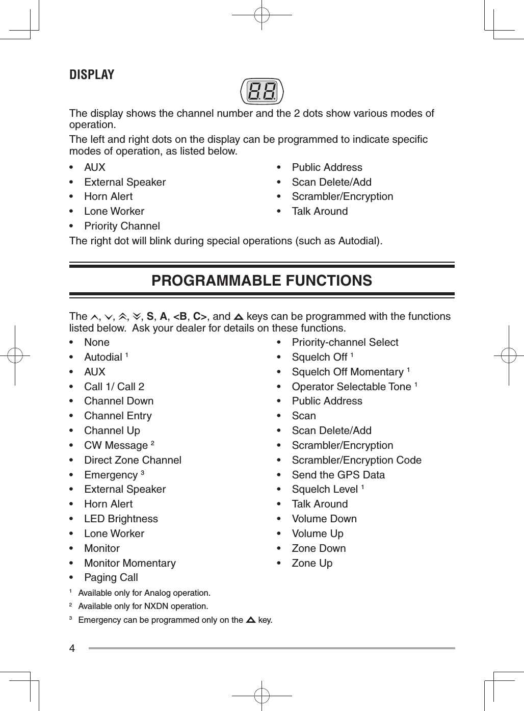
![9FleetSync: ALPHANUMERIC 2-WAY PAGING FUNCTIONFleetSync is an Alphanumeric 2-way Paging Function and is a protocol owned by JVC KENWOOD Corporation.Note: If set up by your dealer, your transceiver may use the MDC-1200 feature in place of FleetSync. MDC-1200 and FleetSync cannot be operated simultaneously.SELCALL (SELECTIVE CALLING)A Selcall is a voice call to a particular station or to a group of stations.■ Transmitting1 Select your desired zone and channel.2 Press the PTT switch and begin your conversation.■ Receiving If enabled by your dealer, an alert tone will sound and the LED will blink when a Selcall has been received. To respond to the call, press the PTT switch and speak into the microphone.■ Identifi cation Codes An ID code is a combination of a 3-digit Fleet number and a 4-digit ID number. Each transceiver must have its own Fleet and ID number.Note: The ID range may be limited by programming.PAGING CALL1 Select your desired zone and channel.2 Press and hold the key programmed as [Paging Call] for 1 second to transmit your PTT List ID, to request a call.GPS REPORTIf a GPS unit (NMEA-0183 format) is installed on your transceiver, you can press the key programmed as [Send the GPS data] to send your location data.OPERATOR SELECTABLE TONE (OST)You can change the preset encode and decode tones for the selected channel. Up to 16 OST pairs can be pre-programmed by your dealer.1 Select your desired channel.2 Press the key programmed as [Operator Selectable Tone] or press and hold the key.• “ot” appears on the display, followed by the current OST number.3 Press <B and C> to select the desired OST number.4 Use the transceiver the same as in a regular call; press the PTT switch to transmit and release it to receive.5 To exit OST mode and return to the preset encode and decode tones, press S.](https://usermanual.wiki/JVC-KENWOOD/452600/User-Guide-2180760-Page-13.png)
![10ADVANCED OPERATIONSEMERGENCY CALLSIf your transceiver has been programmed with the Emergency function, you can make emergency calls.1 Press and hold the key programmed as [Emergency].• Depending on the delay time programmed into your transceiver, the length of time you must hold the [Emergency] key will vary.• When the transceiver enters Emergency mode, the transceiver will change to the Emergency channel and begin transmitting based on how the transceiver is set up.2 To exit Emergency mode, press and hold the [Emergency] key again.• If the Emergency mode completes the preset number of cycles, Emergency mode will automatically end and the transceiver will return to normal.■ Lone Worker Mode Lone Worker Mode is a safety feature built into the transceiver. If the transceiver is not operated for a pre-programmed period of time, the transceiver will emit a tone and automatically enter Emergency operation. Press the key programmed as [Lone Worker] to toggle the Lone Worker function ON or OFF.• “Ln” appears on the display while Lone Worker is activated.TALK AROUNDDuring interruptions in service (such as a power failure), you can continue to communicate by using the Talk Around feature. Talk Around allows you to communicate directly with other transceivers without the use of a repeater, as long they are not too far away or there are no geographical obstacles in the way.Press the key programmed as [Talk Around] to toggle the Talk Around function ON or OFF.• “tA” appears on the display while Talk Around is activated.SCRAMBLER/ ENCRYPTIONThe Scrambler (analog) and Encryption (NXDN) function allows you to hold a conversation in complete privacy. When activated, any other party listening in on your channel will be unable to understand your conversation. Press this key to toggle the Scrambler/ Encryption function ON or OFF.Press the key programmed as [Scrambler/Encryption] to toggle the Scrambler/ Encryption function ON or OFF.• “Sr”(analog)/ ”Ec”(NXDN) appears on the display while the Scrambler/ Encryption is activated.You can change the scrambler/ encryption codes:](https://usermanual.wiki/JVC-KENWOOD/452600/User-Guide-2180760-Page-14.png)
![111 Press and hold the key programmed as [Scrambler/Encryption code] for 2 seconds.• “co” (code) appears on the display, followed by the current scrambler/ encryption code.2 Press <B and C> to select your desired scrambler/ encryption code.3 Press S or to store the new setting.• After changing your scrambler/ encryption code, be sure to inform all of your group members of the new code so they can also reset their transceivers. The scrambler/ encryption function will not work with transceivers set up with different scrambler/ encryption codes.MONITOR/ SQUELCH OFFYou can use the key programmed as [Monitor] or [Squelch Off] to listen to weak signals that you cannot hear during normal operation and to adjust the volume when no signals are present on your selected channel.Your dealer can program a key with one of 4 functions:• Monitor: Press to deactivate QT, DQT, DTMF, FleetSync Signaling, or NXDN. Press again to return to normal operation.• Monitor Momentary: Press and hold to deactivate QT, DQT, DTMF, FleetSync Signaling, or NXDN. Release to return to normal operation.• Squelch Off: Press to hear background noise. Press again to return to normal operation.• Squelch Off Momentary: Press and hold to hear background noise. Release to return to normal operation.■ Squelch Level If a key has been programmed as [Squelch Level], you can readjust your transceiver’s squelch level:1 Press the key programmed as [Squelch Level].• “SL” appears on the display, followed by the current squelch level.2 Press <B and C> to select the desired squelch level from 0 to 9.3 Press S or to store the new setting.PUBLIC ADDRESS (PA)The PA system can only be used with an optional relay unit and external speaker.1 Press the key programmed as [Public Address] to activate the Public Address function.• “PA” appears on the display.2 Press and hold the PTT switch, then speak into the microphone to make your address through the external speaker.3 Press the [Public Address] key again to exit Public Address.HORN ALERTThe Horn Alert function can only be used with an optional relay unit. Press the key programmed as [Horn Alert] to toggle the Horn Alert function ON or OFF.• “HA” appears on the display while Horn Alert is activated.](https://usermanual.wiki/JVC-KENWOOD/452600/User-Guide-2180760-Page-15.png)
![12BACKGROUND OPERATIONSTIME-OUT TIMER (TOT) The Time-out Timer is used to prevent you from using a channel for an extended duration. If you continuously transmit for a preset time, the transceiver will stop transmitting and an alert tone will sound. Release the PTT switch.AUXILIARY PORTPress the key programmed as [AUX] to activate the auxiliary port. The auxiliary port is used with optional boards.• “AU” appears on the display when the auxiliary port is active.DISPLAY BRIGHTNESSYou can cycle the display brightness between high, low, and off by pressing the key programmed as [LED Brightness].DIRECT ZONE CHANNELPress the key programmed as [Direct Zone Channel] to immediately select the lowest channel of the lowest zone.BUSY CHANNEL LOCKOUT (BCL)When activated, BCL prevents you from interfering on a channel that is already in use. Pressing the PTT switch will cause an alert tone to sound and the transceiver will not transmit. Release the PTT switch to stop the tone.Note: Ask your dealer for an explanation on how BCL functions when using QT, DQT, RAN, or Optional signaling.If BCL Override has been programmed, you can transmit over the current signal:1 Press and hold the PTT switch.• If the channel is already in use, a warning tone will sound.2 Quickly release and then press the PTT switch again.3 Speak into the transceiver as you would during a normal call.PTT IDPTT ID is the transceiver unique ID code which is sent each time the PTT switch is pressed and/or released.Note: PTT ID can be made only in analog operation.COMPANDERIf programmed by your dealer for a channel, the compander will remove excessive noise from transmitted signals, to provide higher clarity of signals.Note: The compander is used only in analog operation.VOICE ANNOUNCEMENTWhen changing the zone/ channel, an audio voice will announce the new zone/ channel number.](https://usermanual.wiki/JVC-KENWOOD/452600/User-Guide-2180760-Page-16.png)