JVC KENWOOD 475700 UHF DIGITAL TRANSCEIVER User Manual
JVC KENWOOD Corporation UHF DIGITAL TRANSCEIVER Users Manual
UserManual.wiki
>
JVC KENWOOD
>
475700 User Manual
Users Manual
Navigation menu
Upload a User Manual
Namespaces
Wiki Guide
HTML
PDF
Info
Views
User Manual
Discussion / Help
Navigation
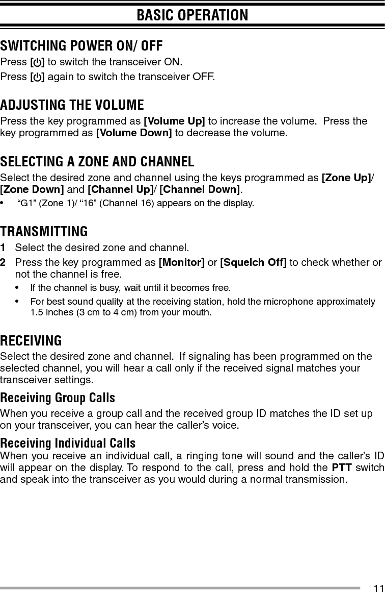
![11BASIC OPERATIONSWITCHING POWER ON/ OFFPress [ ] to switch the transceiver ON.Press [] again to switch the transceiver OFF.ADJUSTING THE VOLUMEPress the key programmed as [Volume Up] to increase the volume. Press the key programmed as [Volume Down] to decrease the volume.SELECTING A ZONE AND CHANNELSelect the desired zone and channel using the keys programmed as [Zone Up]/ [Zone Down] and [Channel Up]/ [Channel Down].• “G1” (Zone 1)/ “16” (Channel 16) appears on the display.TRANSMITTING1 Select the desired zone and channel.2 Press the key programmed as [Monitor] or [Squelch Off] to check whether or not the channel is free.• If the channel is busy, wait until it becomes free.• For best sound quality at the receiving station, hold the microphone approximately 1.5 inches (3 cm to 4 cm) from your mouth.RECEIVINGSelect the desired zone and channel. If signaling has been programmed on the selected channel, you will hear a call only if the received signal matches your transceiver settings.Receiving Group CallsWhen you receive a group call and the received group ID matches the ID set up on your transceiver, you can hear the caller’s voice.Receiving Individual CallsWhen you receive an individual call, a ringing tone will sound and the caller’s ID will appear on the display. To respond to the call, press and hold the PTT switch and speak into the transceiver as you would during a normal transmission.](https://usermanual.wiki/JVC-KENWOOD/475700/User-Guide-2770439-Page-13.png)