JVC KENWOOD 478500 700/800MHz DIGITAL TRANSCEIVER with Bluetooth User Manual B5A 0868 00 Cover indd
JVC KENWOOD Corporation 700/800MHz DIGITAL TRANSCEIVER with Bluetooth B5A 0868 00 Cover indd
Contents
- 1. Users Manual - 1 of 2
- 2. Users Manual - 2 0f 2
- 3. Users Manual
- 4. User Manual
Users Manual - 1 of 2

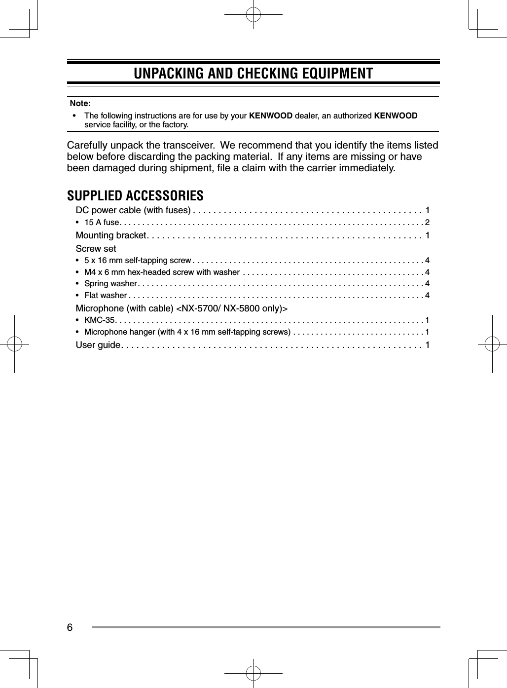
![9ORIENTATIONOPERATION PANEL (ATTACHED PANEL OR KCH-19)ab cgefhda [ ] (Power) switch Press to switch the transceiver ON or OFF.b [ ] / [ ] keys Press to activate its programmable function. The default key setting is [Volume Up]/ [Volume Down]. c [ ] / [ ] keys Press to activate its programmable function. The default key setting is [Channel Up]/ [Channel Down].d Illumination sensor Sensor for Auto Dimmer Function.e Microphone jackInsert the microphone plug into this jack.f TX/RX IndicatorThe indicator lights in different colors to indicate the current status of the transceiver.Lights red while transmitting and green while receiving. g [ ] / [ ] / [ ] / [ ] / [ ] / [ ] / Auxiliary (orange) keys Press to activate their programmable functions. [ ] : The default key setting is [Clear]. [ ] : The default key setting is [Menu]. [ ] : The default key setting is [Squelch Off Momentary]. [ ] : The default key setting is [Zone Down]. [ ] : The default key setting is [Zone Up]. [ ] : The default key setting is [Function]. Auxiliary (orange) : The default key setting is [None].h SpeakerInternal speaker.For details on programming functions to the keys on your transceiver, please contact your dealer or refer to the instruction manual available from the following URL.http://manual2.jvckenwood.com/en_contents/search/](https://usermanual.wiki/JVC-KENWOOD/478500.Users-Manual-1-of-2/User-Guide-2709873-Page-10.png)
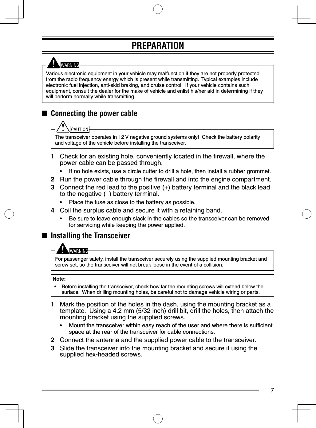
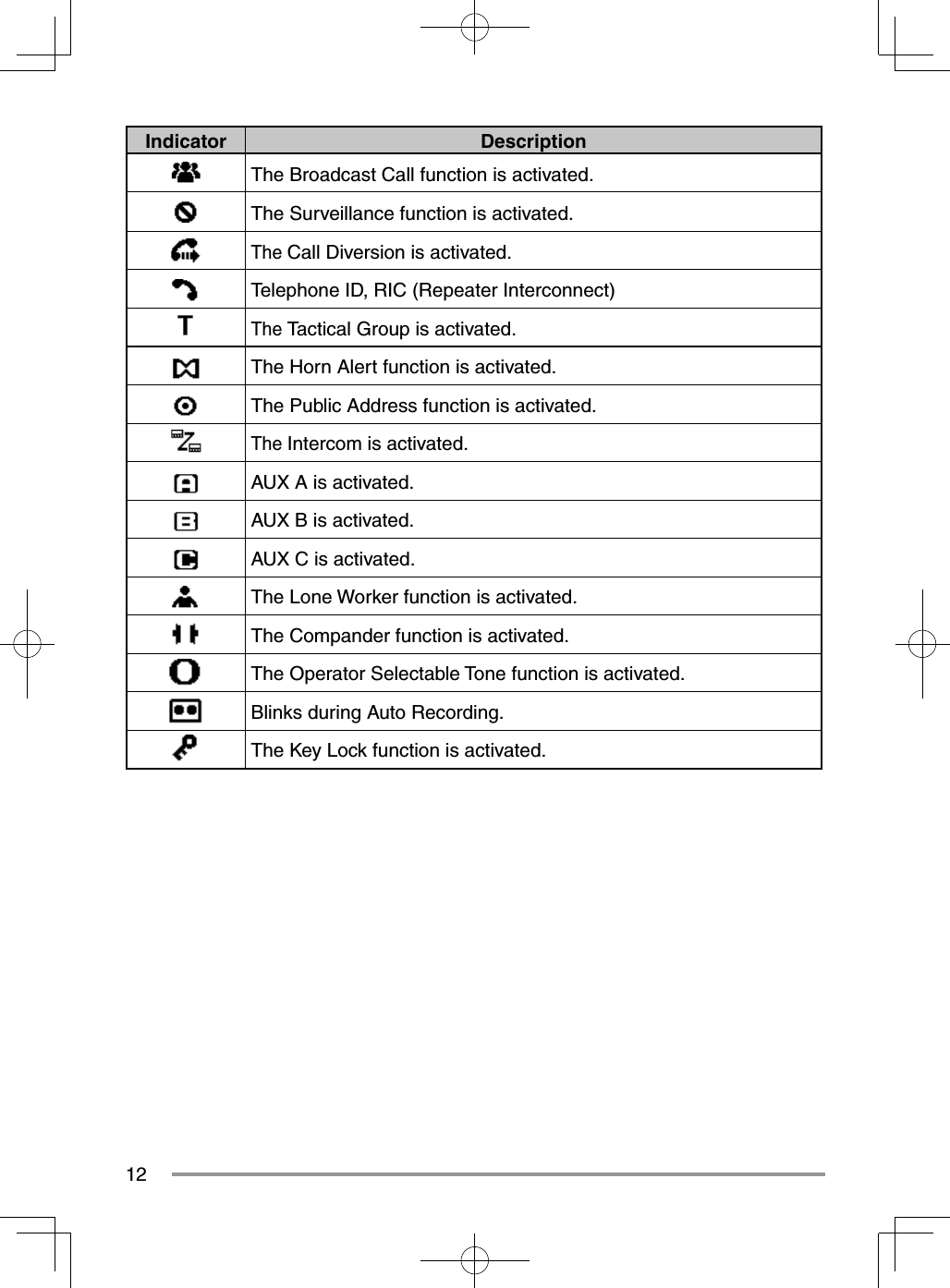
![10DISPLAYBasic FrameFunction Indicator AreaMain AreaKey Guide AreaDisplay Area DescriptionFunction Indicator Area Displays the various function indicators, signal strength indicator and clock.Main Area Display the information of the transceiver such as Channel number and Zone number. Key Guide Area Display the key functions for [ ], [ ], [ ] and [ ] keys.Function IndicatorIndicator DescriptionDisplays the signal strength.In Band 1In Band 2In Band 3The channel is using high transmit power. The channel is using medium transmit power.The channel is using low transmit power.In Digital mode (Digital Channel)In Analog mode (Analog Channel)In Digital mode (Mixed Channel)In Analog mode (Mixed Channel)The Bluetooth function is activated.Connected to Bluetooth device.](https://usermanual.wiki/JVC-KENWOOD/478500.Users-Manual-1-of-2/User-Guide-2709873-Page-11.png)
![13BASIC OPERATIONSWITCHING POWER ON/ OFFPress [ ] to switch the transceiver ON.Press [] again to switch the transceiver OFF.ADJUSTING THE VOLUMEPress the key programmed as [Volume Up] to increase the volume. Press the key programmed as [Volume Down] to decrease the volume.SELECTING A ZONE AND CHANNELSelect the desired zone and channel using the keys programmed as [Zone Up]/ [Zone Down] and [Channel Up]/ [Channel Down].• The transceivers may have names programmed for zones and channels. The zone name and channel name can contain up to 16 and 14 characters respectively. While selecting a zone, the zone name will appear above the channel name.• If programmed by your dealer, your transceiver will announce the zone and channel numbers as you change them.TRANSMITTING1 Select the desired zone and channel.2 Press the PTT switch and speak into the microphone. Release the PTT switch to receive.• The LED indicator lights red while transmitting and green while receiving a signal. This indicator can also be disabled by your dealer.• For best sound quality at the receiving station, hold the microphone approximately 1.5 inches (3 cm to 4 cm) from your mouth.RECEIVINGSelect the desired zone and channel. If signaling has been programmed on the selected channel, you will hear a call only if the received signal matches your transceiver settings.](https://usermanual.wiki/JVC-KENWOOD/478500.Users-Manual-1-of-2/User-Guide-2709873-Page-14.png)