JVC KENWOOD 479100 UHF DIGITAL TRANSCEIVER User Manual 1 of 2
JVC KENWOOD Corporation UHF DIGITAL TRANSCEIVER Users Manual 1 of 2
UserManual.wiki
>
JVC KENWOOD
>
479100 User Manual
>
Users Manual - 1 of 2
Contents
1.
Users Manual - 1 of 2
2.
Users Manual - 2 of 2
3.
Users Manual
Users Manual - 1 of 2
Navigation menu
Upload a User Manual
Namespaces
Wiki Guide
HTML
PDF
Info
Views
User Manual
Discussion / Help
Navigation
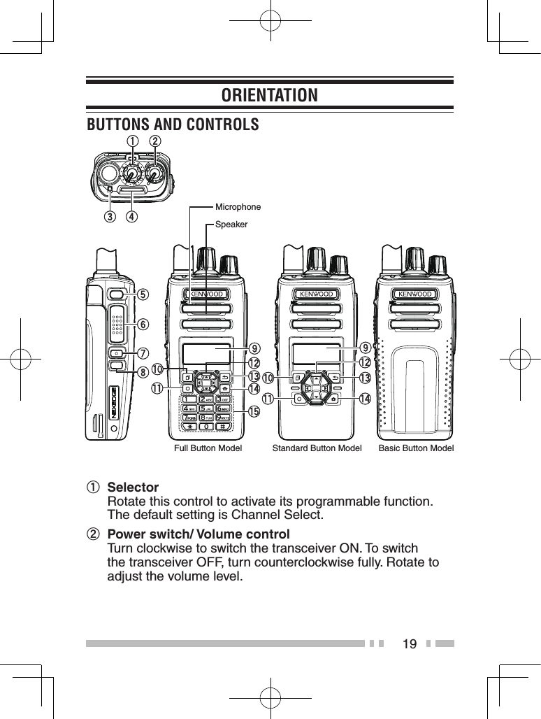
![20c Transmit/ Receive/ Battery low indicator The indicator lights in different colors to indicate the current status of the transceiver. Lights red while transmitting and green while receiving. Flashes red when the battery power is low while transmitting. Replace or recharge the battery pack when the battery power is low.Note: •This indicator can be disabled by your dealer.d Light Bar This Light Bar lights when selecting a channel or upon reception.Note: •This indicator can be disabled by your dealer.e Auxiliary (orange) button Press to activate its programmable function. f PTT (Push-To-Talk) switch Press and hold, then speak into the microphone to call a station.g Side 1 button Press to activate its programmable function. The default button setting is [Squelch Off Momentary]. h Side 2 button Press to activate its programmable function. The default button setting is [Backlight]. i LCD Display Refer to the display. {p. 20}j [ ] button Press to activate its programmable function. The default button setting is [Menu].k [ ] button Press to activate its programmable function. The default button setting is [Function].](https://usermanual.wiki/JVC-KENWOOD/479100.Users-Manual-1-of-2/User-Guide-3389221-Page-22.png)
![21l 4-way D-pad (Full Button Model/ Standard Button Model) Press to activate its programmable function.[ ] : The default setting is [None].[ ] : The default setting is [None].[ ] : The default setting is [Zone Up].[ ] : The default setting is [Zone Down].m [ ] button Press to activate its programmable function. The default button setting is [None].n [ ] button Press to activate its programmable function. The default button setting is [Clear].o Keypad (Full Button Model only) The keypad buttons can also be programmed with secondary functions if a programmable function buttons is programmed as Function.For details on programming functions to the buttons on your transceiver, please contact your dealer or refer to the instruction manual available from the following URL.http://manual.kenwood.com/en_contents/search/keyword](https://usermanual.wiki/JVC-KENWOOD/479100.Users-Manual-1-of-2/User-Guide-3389221-Page-23.png)
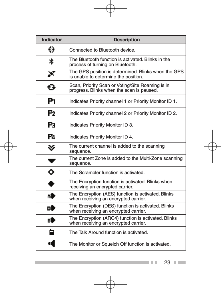
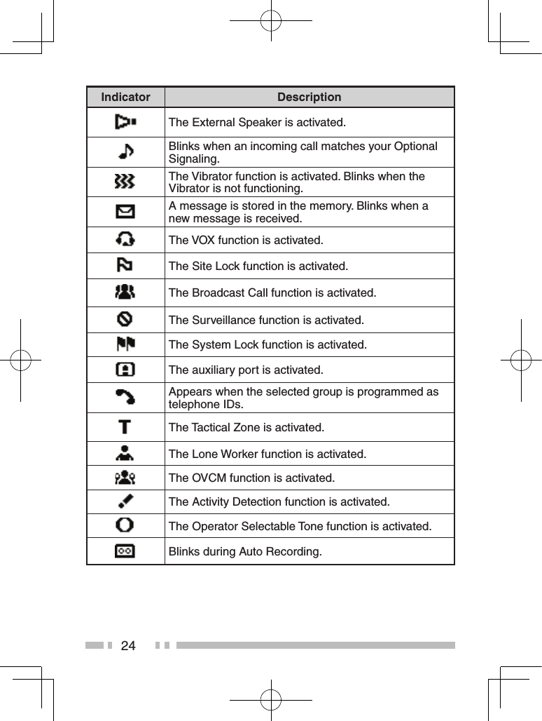
![22DisPLay Display Area DescriptionFunction Indicator AreaDisplay the various function Icons ,signal strength indicator and battery power indicator and clock.Main Area Display the information of the transceiver such as Channel number and Zone number.Button Guide Area Display the button functions for [ ],[ ] and [ ].Basic Frame Function Indicator Indicator DescriptionDisplays the signal strength.Displays the battery power.The channel is using high transmit power. The channel is using medium transmit power.The channel is using low transmit power.In Digital mode (Digital Channel)In Analog mode (Analog Channel)In Digital mode (Mixed Channel)In Analog mode (Mixed Channel)Function Indicator AreaMain AreaButton Guide Area](https://usermanual.wiki/JVC-KENWOOD/479100.Users-Manual-1-of-2/User-Guide-3389221-Page-24.png)
![25BasiC oPerationssWitChinG PoWer on/ oFFTurn the Power switch/ Volume control clockwise to switch the transceiver power ON.Turn the Power switch/ Volume control counter-clockwise to switch the transceiver power OFF.aDJUstinG the voLUMerotate the Power switch/ Volume control to adjust the volume.seLeCtinG a Zone anD ChanneL1 Select the desired zone using the Selector or 4-way D-pad or the buttons programmed as [Zone Up]/ [Zone Down]. Each zone contains a group of channels.2 Select the desired channel using the Selector or 4-way D-pad or the buttons programmed as [Channel Up]/ [Channel Down]. Each channel is programmed with settings for transmitting and receiving. •The default setting for the Selector is [Channel Select]. • The transceivers may have names programmed for zones and channels. The zone name and channel name can contain up to 12 and 14 characters respectively. While selecting a zone, the zone name will appear above the channel name. •If programmed by your dealer, your transceiver will announce the zone and channel numbers as you change them.](https://usermanual.wiki/JVC-KENWOOD/479100.Users-Manual-1-of-2/User-Guide-3389221-Page-27.png)
![26transMittinG1 Select the desired zone and channel using the Selector or 4-way D-pad and the [Zone up]/ [Zone Down] or [Channel up]/ [Channel Down] buttons.2 Press the PTT switch and speak into the microphone. Release the PTT switch to receive. •The LED indicator lights red while transmitting and green while receiving a signal. This indicator can also be disabled by your dealer. •For best sound quality at the receiving station, hold the microphone approximately 3 cm to 4 cm (1.5 inches) from your mouth.reCeivinGSelect the desired zone and channel. If signaling has been programmed on the selected channel, you will hear a call only if the received signal matches your transceiver settings.](https://usermanual.wiki/JVC-KENWOOD/479100.Users-Manual-1-of-2/User-Guide-3389221-Page-28.png)