JVC BR HD50E HD50EC User Manual HD50E, HD50U LLT0088 001C H
BR-HD50U BR-HD50U LLT0088-001C-H English,
User Manual: JVC BR-HD50E BR-HD50E, BR-HD50U nglish,
Open the PDF directly: View PDF ![]() .
.
Page Count: 91
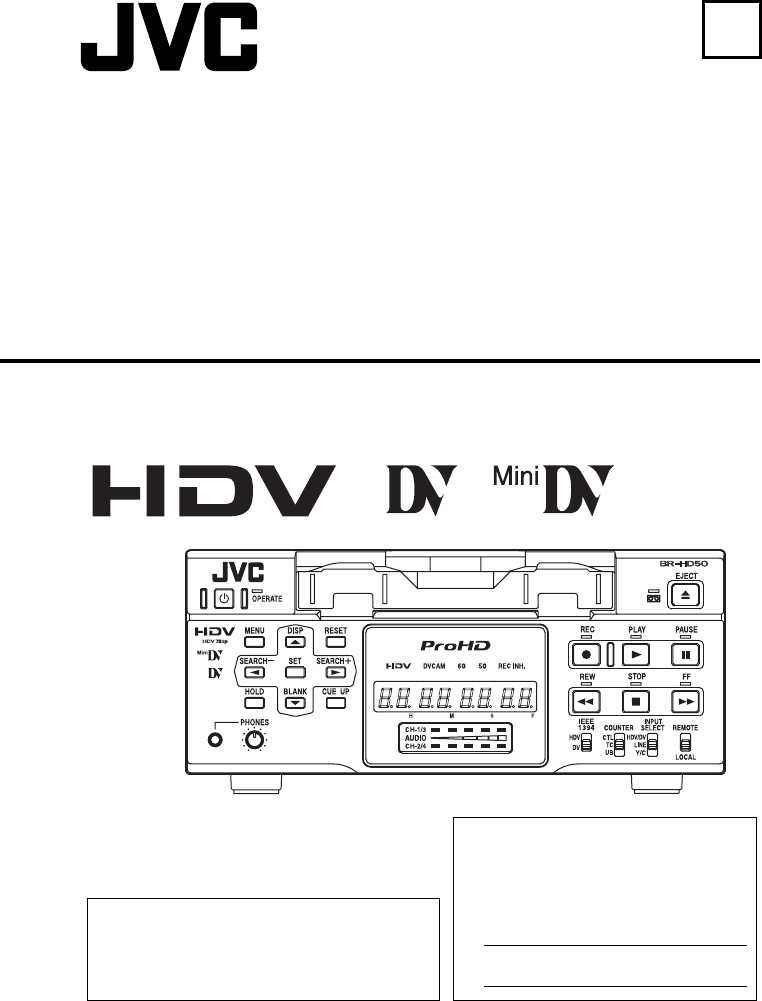
BR-HD50 HD VIDEO CASSETTE RECORDER
BR-HD50
E
HD VIDEO CASSETTE RECORDER
INSTRUCTION MANUAL
(A)
LLT0088-001C
Thank you for purchasing this JVC product.
Before operating this unit, please read the
instructions carefully to unsure the best possi-
ble performance.
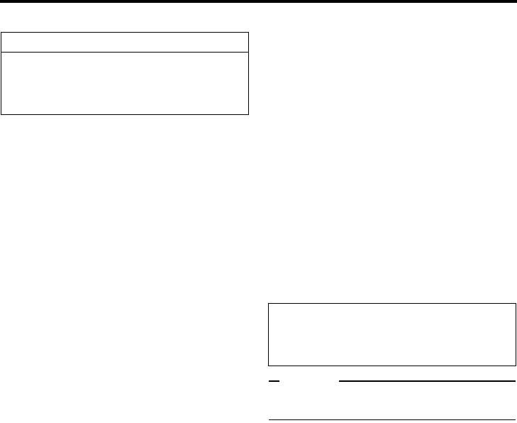
For Customer Use:
Enter below the Serial No. which is
located on the rear of cabinet. Retain
this information for future reference.
Model No. BR-HD50U/BR-HD50E
Serial No.
2008 Victor Company of Japan, Limited LLT0088-001C

I
IMPORTANT SAFEGUARDS
1. Read all of these instructions.
2. Save these instructions for later use.
3. All warnings on the product and in the operating instructions should be adhered to.
4. Unplug this appliance system from the wall outlet before cleaning. Do not use liquid cleaners or aerosol
cleaners. Use a damp cloth for cleaning.
5. Do not use attachments not recommended by the appliance manufacturer as they may cause hazards.
6. Do not use this appliance near water - for example, near a bathtub, washbowl, kitchen sink, or laundry tub,
in a wet basement, or near a swimming pool, etc.
7. Do not place this appliance on an unstable cart, stand, or table. The appliance may
fall, causing serious injury to a child or adult, and serious damage to the appliance.
Use only with a cart or stand recommended by the manufacturer, or sold with the
appliance.
Wall or shelf mounting should follow the manufacturer’s instructions, and should
use a mounting kit approved by the manufacturer.
An appliance and cart combination should be moved with care. Quick stops,
excessive force, and uneven surfaces may cause the appliance and cart combina-
tion to overturn.
8. Slots and openings in the cabinet and the back or bottom are provided for ventila-
tion, and to insure reliable operation of the appliance and to protect it from over-
heating, these openings must not be blocked or covered. The openings should
never be blocked by placing the appliance on a bed, sofa, rug, or other similar surface. This appliance
should never be placed near or over a radiator or heat register. This appliance should not be placed in a
built-in installation such as a bookcase unless proper ventilation is provided.
9. This appliance should be operated only from the type of power source indicated on the marking label. If
you are not sure of the type of power supplied to your home, consult your dealer or local power company.
For appliance designed to operate from battery power, refer to the operating instructions.
10. This appliance system is equipped with a 3-wire grounding type plug (a plug having a third (grounding
pin). This plug will only fit into a grounding-type power outlet. This is a safety feature. If you are unable to
insert the plug into the outlet, contact your electrician to replace your obsolete outlet. Do not defeat the
safety purpose of the grounding plug.
11. For added protection for this product during a lightning storm, or when it is left unattended and unused for
long periods of time, unplug it from the wall outlet and disconnect the antenna or cable system. This will
prevent damage to the product due to lightning and power-line surges.
12. Do not allow anything to rest on the power cord. Do not locate this appliance where the cord will be
abused by persons walking on it.
13. Follow all warnings and instructions marked on the appliance.
14. Do not overload wall outlets and extension cords as this can result in fire or electric shock.
15. Never push objects of any kind into this appliance through cabinet slots as they may touch dangerous volt-
age points or short out parts that could result in a fire or electric shock. Never spill liquid of any kind on the
appliance.
16. Do not attempt to service this appliance yourself as opening or removing covers may expose you to dan-
gerous voltage or other hazards. Refer all servicing to qualified service personnel.
17. Unplug this appliance from the wall outlet and refer servicing to qualified service personnel under the fol-
lowing conditions:
a.When the power cord or plug is damaged or frayed.
b.If liquid has been spilled into the appliance.
c.If the appliance has been exposed to rain or water.
d.If the appliance does not operate normally by following the operating instructions. Adjust only those con-
trols that are covered by the operating instructions as improper adjustment of other controls may
result in damage and will often require extensive work by a qualified technician to restore the appli-
ance to normal operation.
e.If the appliance has been dropped or the cabinet has been damaged.
f. When the appliance exhibits a distinct change in performance - this indicates a need for service.
18. When replacement parts are required, be sure the service technician has used replacement parts speci-
fied by the manufacturer that have the same characteristics as the original part. Unauthorized substitu-
tions may result in fire, electric shock, or other hazards.
19. Upon completion of any service or repairs to this appliance, ask the service technician to perform routine
safety checks to determine that the appliance is in safe operating condition.
II
SAFETY PRECAUTIONS (For USA & Canada)
CAUTION
RISK OF ELECTRIC
SHOCK DO NOT OPEN
CAUTION: TO REDUCE THE RISK OF ELECTRIC SHOCK,
DO NOT REMOVE COVER (OR BACK).
NO USER-SERVICEABLE PARTS INSIDE.
REFER SERVICING TO QUALIFIED SERVICE PERSONNEL
The lightning flash with arrowhead symbol,
within an equilateral triangle, is intended to
alert the user to the presence of uninsulated
“dangerous voltage” within the product’s enclo-
sure that may be of sufficient magnitude to
constitute a risk of electric shock to persons.
The exclamation point within an equilateral tri-
angle is intended to alert the user to the pres-
ence of important operating and maintenance
(servicing) instructions in the literature accom-
panying the appliance.
WARNING:
TO REDUCE THE RISK OF FIRE OR ELEC-
TRIC SHOCK, DO NOT EXPOSE THIS
APPLIANCE TO RAIN OR MOISTURE.
This unit should be used with 120 V AC only.
CAUTION:
To prevent electric shocks and fire hazards, DO
NOT use any other power source.
NOTE:
The rating plate (serial number plate) is on the rear of the unit.
INFORMATION
This equipment has been tested and found to comply with the
limits for a Class B digital device, pursuant to Part 15 of the
FCC Rules. These limits are designed to provide reasonable
protection against harmful interference in a residential installa-
tion. This equipment generates, uses, and can radiate radio
frequency energy and, if not installed and used in accordance
with the instructions, may cause harmful interference to radio
communications. However, there is no guarantee that interfer-
ence will not occur in a particular installation.
If this equipment does cause harmful interference to radio or
television reception, which can be determined by turning the
equipment off and on, the user is encouraged to try to correct
the interference by one or more of the following measures:
zReorient or relocate the receiving antenna.
zIncrease the separation between the equipment and
receiver.
zConnect the equipment into an outlet on a circuit different
from that to which the receiver is connected.
zConsult the dealer or an experienced radio/TV technician
for help.
CAUTION
CHANGES OR MODIFICATIONS NOT APPROVED BY JVC
COULD VOID USER’S AUTHORITY TO OPERATE THE
EQUIPMENT.
THIS DEVICE COMPLIES WITH PART 15 OF THE FCC
RULES. OPERATION IS SUBJECT TO THE FOLLOWING TWO
CONDITIONS: (1) THIS DEVICE MAY NOT CAUSE HARMFUL
INTERFERENCE, AND (2) THIS DEVICE MUST ACCEPT ANY
INTERFERENCE RECEIVED, INCLUDING INTERFERENCE
THAT MAY CAUSE UNDESIRED OPERATION.
ATTENTION
RISQUE D’ELECTRO-
CUTION NE PAS
OUVRIR
ATTENTION: POUR EVITER TOUT RISQUE D’ELECTROCUTION
NE PAS OUVRIR LE BOITER.
AUCUNE PIECE INTERIEURE N’EST
A REGLER PAR L’UTILISATEUR.
SE REFERER A UN AGENT QUALIFIE EN CAS DE PROBLEME.
Le symbole de l’éclair à l’intérieur d’un triangle
équilatéral est destiné à alerter l’utilisateur sur
la présence d’une “tension dangereuse” non
isolée dans le boîtier du produit. Cette tension
est suffisante pour provoquer l’électrocution
de personnes.
Le point d’exclamation à l’intérieur d’un trian-
gle équilatéral est destiné à alerter l’utilisateur
sur la présence d’opérations d’entretien impor-
tantes au sujet desquelles des renseigne-
ments se trouvent dans le manuel
d’instructions.
* Ces symboles ne sont utilisés qu’aux Etats-
Unis.
AVERTISSEMENT:
POUR EVITER LES RISQUES D’INCENDIE
OU D’ELECTROCUTION, NE PAS
EXPOSER L’APPAREIL A L’HUMIDITE OU A
LA PLUIE.
Ce magnétoscope ne doit être utilisé que sur du
courant alternatif en 120 V.
ATTENTION:
Afin d’éviter tout resque d’incendie ou d’électro-
cution, ne pas utiliser d’autres sources d’alimen-
tation électrique.
REMARQUE:
La plaque d’identification (numéro de série) se trouve sur le
panneau arrière de l’appareil.
WARNING:
The battery used in the BR-HD50 must be replaced by a JVC
authorized service dealer only.
INFORMATION (FOR CANADA)
RENSEIGNEMENT (POUR CANADA)
This Class B digital apparatus complies with Canadian
ICES-003.
Cet appareil numérique de la Class B est conforme à la
norme NMB-003 du Canada.
III
Supplement
This equipment is in conformity with the provisions and protection requirements of the corresponding
European Directives. This equipment is designed for professional video appliances and can be used in
the following environments:
Residential (including both of the location type class 1 and 2 found in IEC 1000-2-5)
Commercial and light industrial (including, for example, theatres)
Urban outdoors (based on the definition of location type class 6 in IEC 1000-2-5)
In order to keep the best performance and furthermore for electromagnetic compatibility we recom-
mend to use cables not exceeding the following lengths:
The inrush current of this apparatus is 12.1 amperes.
Caution:
Where there are strong electromagnetic waves or magnetism, for example near a radio or TV trans-
mitter, transformer, motor, etc., the picture and sound may be disturbed. In such a case, please keep
the apparatus away from the sources of the disturbance.
Port Cable Length
AUDIO SHIELDED CABLE 10 meters
LINE COAXIAL CABLE 10 meters
COMPONENT COAXIAL CABLE 10 meters
Y/C COAXIAL CABLE 10 meters
IEEE1394 SHIELDED TWIST PAIR CABLE 4.5 meters
HDMI SHIELDED TWIST PAIR CABLE 5 meters
REMOTE SHIELDED TWIST PAIR CABLE 5 meters
Information for Users on Disposal of Old Equipment
[European Union]
This symbol indicates that the electrical and electronic equipment should not be dis-
posed as general household waste at its end-of-life. Instead, the product should be
handed over to the applicable collection point for the recycling of electrical and elec-
tronic equipment for proper treatment, recovery and recycling in accordance with
your national legislation.
By disposing of this product correctly, you will help to conserve natural resources and
will help prevent potential negative effects on the environment and human health
which could otherwise be caused by inappropriate waste handling of this product.
For more information about collection point and recycling of this product, please con-
tact your local municipal office, your household waste disposal service or the shop
where you purchased the product.
Penalties may be applicable for incorrect disposal of this waste, in accordance with
national legislation.
(Business users)
If you wish to dispose of this product, please visit our web page www.jvc-europe.com
to obtain information about the take-back of the product.
[Other Countries outside the European Union]
If you wish to dispose of this product, please do so in accordance with applicable
national legislation or other rules in your country for the treatment of old electrical
and electronic equipment.
Attention:
This symbol is
only valid in
the European
Union.
IV
SAFETY PRECAUTIONS (For Europe)
Warning Notice
FOR YOUR SAFETY (Australia)
1. Insert this plug only into effectively earthed three-pin power
outlet.
2. If any doubt exists regarding the earthing, consult a quali-
fied electrician.
3. Extension cord, if used, must be three-core correctly wired.
IMPORTANT (In the United Kingdom)
Mains Supply (AC 230 V C)
WARNING - THIS APPARATUS
MUST BE EARTHED
The wires in this mains lead are coloured in accordance with
the following code;
GREEN-and-YELLOW : EARTH
BLUE : NEUTRAL
BROWN : LIVE
As the colours of the wires in the mains lead of this apparatus
may not correspond with the coloured markings identifying the
terminals in your plug, proceed as follows.
The wire which is coloured GREEN-AND-YELLOW must be
connected to the terminal in the plug which is marked with the
letter E or by the safety earth symbol U or coloured GREEN
or GREEN-AND-YELLOW. The wire which is coloured BLUE
must be connected to the terminal which is marked with the
letter N or which is coloured BLACK. The wire which is
coloured BROWN must be connected to the terminal which is
marked with the letter L or coloured RED.
POWER SYSTEM
Connection to the mains supply
This unit operates on voltage of 220 V to 240 V AC, 50 Hz/60
Hz.
WARNING:
TO REDUCE THE RISK OF FIRE OR ELEC-
TRIC SHOCK, DO NOT EXPOSE THIS
APPLIANCE TO RAIN OR MOISTURE.
CAUTION
To prevent electric shock, do not open the cabinet. No user
serviceable parts inside. Refer servicing to qualified service
personnel.
Note:
The rating plate and the safety caution are on the rear of the
unit.
The OPERATE button does not completely shut off mains
power from the unit, but switches operating current on and off.
WARNING
It should be noted that it may be unlawful to re-record pre-
recorded tapes, records, or discs without the consent of the
owner of copyright in the sound or video recording, broadcast,
or cable programme and in any literary, dramatic, musical or
artistic work embodied therein.
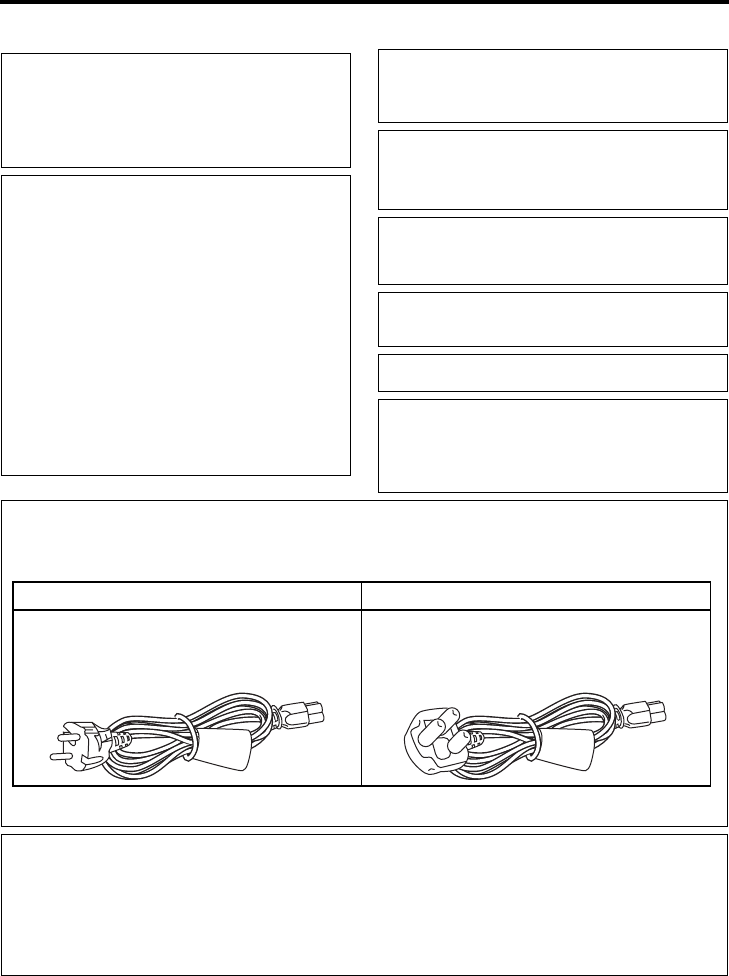
Caution for AC Mains Lead
FOR YOUR SAFETY PLEASE READ THE FOLLOWING TEXT CAREFULLY.
This product is equipped with 2 types of AC cable. One is for continental Europe, etc. and the other one is only for U.K.
Appropriate mains cable must be used in each local area, since the other type of mains cable is not suitable.
FOR CONTINENTAL EUROPE, ETC. FOR U.K. ONLY
Not to be used in the U.K. If the supplied plug is not suitable for your
socket outlet, it should be cut off and fitted with
an appropriate one.
Dear Customer,
This apparatus is in conformance with the valid European directives and standards regarding electromagnetic compatibility and elec-
trical safety.
European representative of Victor Company of Japan, Limited is:
JVC Technical Services Europe GmbH
Postfach 10 05 04
61145 Friedberg
Germany

E-2
Thank you for purchasing our HD Video
Cassette Recorder BR-HD50
This instruction manual was made for the BR-
HD50U and the BR-HD50E.
Items only applicable to BR-HD50U are labeled
“U model only” or “U only”.
Items only applicable to BR-HD50E are labeled
“E model only” or “E only”.
zHDV 720p format
Records and plays back HD (High-Definition)
video with 720 effective scanlines (progressive
scan).
This unit records 720/24p/25p/30p, 480/60p,
and 576/50p HDV signals from an IEEE1394
terminal. 24p video has the same frame count
as movie film.
zCompatible with DV format
Compatible with DV format for digitally record-
ing SD (Standard-Definition) video.
zCompatible mechanism for standard/mini
DV cassettes
Records and plays back HDV or DV format on
standard and mini size DV cassettes.
(SP mode only)
DVCAM cassettes can be recorded in HDV or
DV format.
Tapes recorded in the DVCAM format can only
be played.
zEquipped with IEEE1394 terminal
Inputs and outputs HDV signals, DV signals,
and digital audio. Capable of exchanging digi-
tal signals with IEEE1394 compatible equip-
ment.
zCompatible with 60Hz/50Hz HD signal for-
mat
Compatible with both 60Hz and 50Hz HD sig-
nal formats. Select this on the Menu screen.
zEquipped with HDMI terminal
Outputs digital video and digital audio.
View HD video on monitors with an HDMI ter-
minal.
zEquipped with COMPONENT OUT terminal
Outputs HD/SD analog video.
View HD video on HD-compatible monitors
with a COMPONENT input terminal.
zOutputs cross-converted video
During HDV/DV signal input or playback, for-
mat converted video can be output from the
HDMI terminal or COMPONENT OUT termi-
nal. Select the output video on the Menu
screen.
zEquipped with composite and Y/C input/
output terminals
Inputs and outputs analog video. Analog video
is recorded in the DV format.
zRS-422A compatible
Connect this unit with the RS-422A compatible
RM-G820 edit controller, and use this unit as a
player.
This can also be connected to RS-422A com-
patible non-linear editing machines.
zEquipped with SERIAL REMOTE terminal
Connect to a wired remote controller for
remote operation of this unit. Or, connect with
a foot switch used for recording operations.
zRecording and playback of time codes
zBackup recording function
With the combined use of other DV machines,
long-time continuous recording is possible.
zMulti-cue up
Up to 5 points of the tape position can be reg-
istered and cued up.
zIndex/blank search function
It can search for positions where index signals
are recorded and unrecorded parts.
zRepeat play function
There are 3 types of repeat function.
(INDEX/ V.END/ TAPE END)
This is an HDV/DV format video cassette recorder. Video cas-
settes with the B or A logo can be used with it.
DVCAM cassettes can be recorded in the HDV/DV format.
MAIN FEATURES
HDV and are trademarks of the Sony
Corporation and the Victor Company of Japan,
Limited.
DVCAM is a trademark of the Sony Corporation.

E-3
Table of Contents
INTRODUCTION
Remarks of usage...............................................4
Cassette tape......................................................5
HDV and DV format ............................................6
Regular maintenance..........................................8
Cleaning tape......................................................9
Condensation......................................................9
NAMES AND FUNCTIONS OF PARTS
Front panel........................................................10
Rear panel ........................................................16
ON-SCREEN DISPLAY
On-screen display.............................................20
Status display ...................................................21
Event/Alarm display ..........................................24
CONNECTION
Connecting video signals..................................26
Connecting audio signals..................................28
Attaching the supplied ferrite core ....................29
Connecting with SERIAL REMOTE terminals
...30
Connecting the AC adapter ..............................31
RECORDING/OUTPUT SIGNAL FORMAT
Inputting analog signal......................................32
Inputting digital signal .......................................33
Playback ...........................................................34
PREPARATION
Turning on/off the power...................................35
Operation method (main unit/remote controller)
and OPERATION LOCK mode.........................36
Loading/Ejecting cassette.................................37
Setting/Displaying date and time ......................38
Selecting HD signal format ...............................40
RECORDING
Settings for analog signal input.........................41
Settings for digital signal input ..........................42
Adjusting audio recording level.........................44
Recording procedure ........................................46
Backup recording function ................................47
Recording with SERIAL REMOTE terminals ....48
PLAYBACK
Playback settings ............................................. 49
Basic playback procedure................................ 51
Special playback functions............................... 52
Search function ................................................ 54
Repeat playback .............................................. 55
Multi cue-up ..................................................... 56
TIME CODE
Displaying the time code.................................. 58
Presetting the time code .................................. 59
Recording the time code .................................. 60
Playing back the time code .............................. 62
EDIT
Using a non-linear editing system.................... 63
MENU SCREENS
Setting the menus............................................ 64
Structure of the Menu screens......................... 66
Description of the Menu screens ..................... 67
OTHERS
Warning display ............................................... 79
Troubleshooting ............................................... 81
Checking the hour meter.................................. 83
Specifications................................................... 84
Supplement...................................................... 86

E-4
INTRODUCTION
Place of storage and use
Avoid storing or using this VCR in the following
places:
zExcessively hot or cold places beyond the
allowable temperature for operation(5°C –
40°C).
zHumid or dry places beyond the allowable
humidity range for operation (30% – 80%
RH).
zDusty or sandy places.
zPlaces exposed to oil, smoke or steam,
such as the kitchen vicinity.
zIntensely vibrating or unstable places.
zPlaces prone to condensation.
zPlaces that generate strong magnetic fields,
e.g., near a transformer or motor.
zPlaces near devices that generate electric
waves, e.g., a transceiver or mobile phone.
zPlaces that generate X-ray radiation or cor-
rosive gases.
Also do not leave the unit for long hours in a
parked car under direct sunlight or near room
heating equipment.
Handling the unit
zDo not place heavy objects on the unit, like
a monitor or TV.
zDo not insert foreign objects into the cas-
sette slot.
zMind your finger when loading a cassette
tape.
Be careful not to get your fingers clamped
when loading the cassette to prevent injury.
zPlace this unit out of reach of young chil-
dren to prevent injury as fingers may get
clamped while a cassette tape is being
loaded.
zDo not block the ventilation openings on the
rear panel.
zAvoid strong impact to the unit. Do not drop
the unit.
zRemove the cassette tape from the cas-
sette slot when transporting the unit.
zRemove the AC adapter to save energy
when the unit is not in use.
Maintaining the unit (Turn off the power
before performing maintenance work.)
Wipe the unit with a soft cloth.
Do not wipe it with thinner or benzene as it
may melt or tarnish the unit surface.
For stubborn stains, use water-diluted neutral
detergent and then wipe it dry.
Always use the supplied AC adapter.
Failure to do so can cause mechanical break-
down or electric shock.
Use the supplied power cord.
Using a different type or damaged cord may
cause fire or electric shock.
Do not use the supplied power cord
for other models.
Remarks of usage
zWhen making an important recording, do not
record within the two or three minutes at the
beginning or end of the tape.
zRecorded video (sound) is meant for per-
sonal entertainment only and must not be
used for other purposes without the prior con-
sent of the copyright owner.
zJVC shall not guarantee the quality of record-
ing and playback should BR-HD50 fail to
function normally due to defects, either of the
unit itself or the video cassette tapes.
E-5
BR-HD50 can record onto and playback standard
DV and mini DV cassette tapes (for SP mode
only).
Use the following JVC cassettes with the B or
A the logo.
Memo
zDVCAM cassette can be recorded in the HDV
or DV format.
zTapes recorded in the DVCAM format can be
played (SP Mode).
zM-DV80 cassettes (mini DV 80min tape) can-
not be used with this unit.
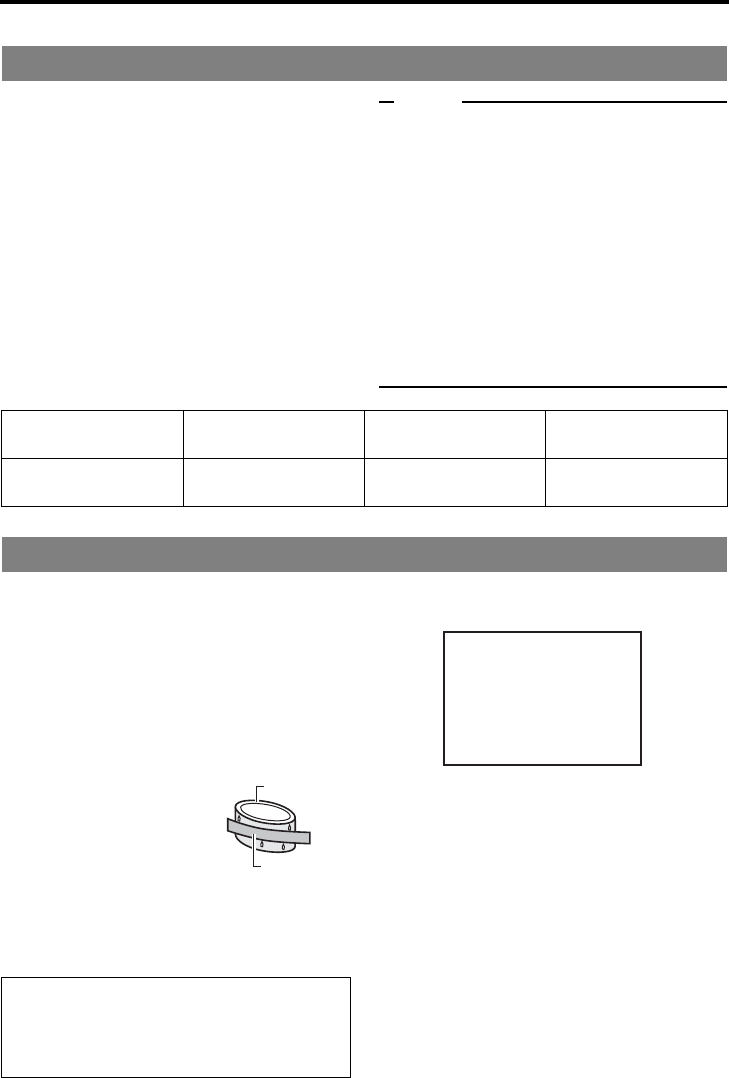
Erasure prevention
DV cassettes have a safety slide at the back to
prevent accidental erasure.
• To prevent accidental erasure of important
records, push the slide to the “SAVE” posi-
tion.
• To record, push the slide to the “REC” posi-
tion.
For recording and storing videotapes in the best condition
Observe the following instructions for the best recording and storage of videotapes.
• Take care of the conditions of handling videotapes.
It is recommended that you record and store videotapes in the environment below.
• Do not leave the videotapes neglected for a long period.
If videotapes are left wound for a long period of time, it may result in distortion of the tape. Also it
may cause tape-to-tape adhesion (known as blocking). It is recommended that videotapes be
unspooled and rewound once a year for refreshing.
• When tapes are not in use, store them in cases and on end.
Storage cases protect videotapes from humidity, dust and ultraviolet. Keep tapes in cases and do
not store them lying flat. When housed in a horizontal position, pressure from other tapes can
cause distortions and deformations of the tape edges.
Cassette tape
zStandard DV cas-
settes
zMini DV cassettes
LA-DV276
LA-DV186
LA-DV124
M-DV63PRO
M-DV63HD
REC
SAVE
Slide
Remarks on the use of tape
zDo not load the videotape in the wrong direction.
zStore the tape only after it has been fully rewound, so as to avoid damaging the tape.
zStore the cassette in places low in humidity, well-ventilated and fungus-proof.
zWhen a cassette tape is used repeatedly, noise may increase due to e.g., dropout, etc. hence
affecting its performance. Do not use dirty or damaged tapes as they will shorten the life span of the
rotation head.
Recording
Storage
Short period
(Up to 10 years)
Long period
(Over 10 years)
Temperature 17°C to 25°C 15°C to 23°C 15°C to 19°C
Humidity 30% to 70% 40% to 55% 25% to 35%
Hourly temperature change Less than 10°C - -
Hourly humidity change Less than 10% - -
E-6
INTRODUCTION
This unit records in HDV or DV format.
DV format is a standard for recording SD (Standard-Definition) video onto DV cassettes or mini DV cas-
settes.
HDV format is a standard for recording HD (High-Definition) video onto DV cassettes or mini DV cas-
settes.
The two HDV recording formats are HDV 720p and HDV 1080i.
HDV 720p : 720p (720 effective scanlines, progressive scan)
HDV 1080i : 1080i (1080 effective scanlines, interlace scan)
This unit supports the HDV 720p format.
HDV and DV signal input/output
HDV signals and DV signals are input/output from the IEEE1394 terminal.
HDV signals from the IEEE1394 terminal are recorded in HDV format.
DV signals from the IEEE1394 terminal are recorded in DV format.
Recorded HDV signals or DV signals are output from the IEEE1394 terminal during playback.
Digital audio is also input/output from the IEEE1394 terminal, together with HDV signals or DV signals.
The front panel IEEE1394 switch must be set on the front panel, according to whether the input/output
signal from the IEEE1394 terminal is in HDV format or DV format.
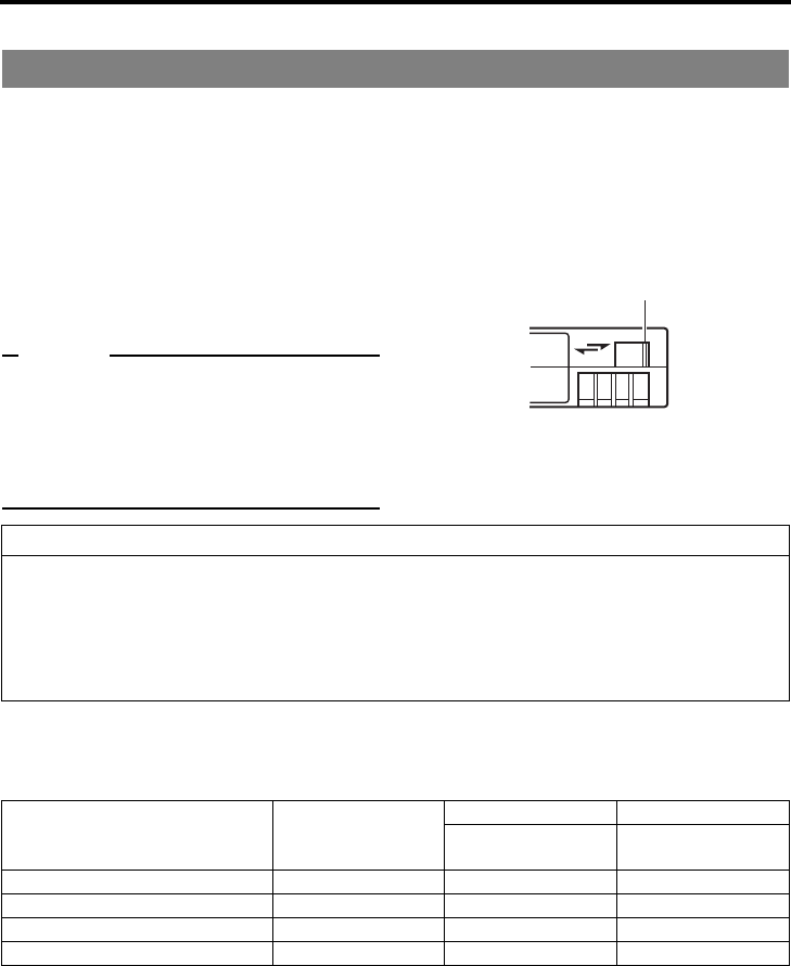
When the input signal or playback signal is in HDV format, the front panel HDV display is lit.
Analog signal input is digitally converted and recorded in DV format.
HD signal format
This unit is compatible with both 60Hz and 50Hz HD signal formats. The HDV signal format must be set
on this unit, according to whether the input/playback HD signal format is 60Hz or 50Hz.
(Set this using 60/50 SEL in the SYSTEM [2/2] Menu screen.)
Menu settings on this unit can be checked by whether the front panel 60 or 50 indicator light is lit.
The field frequency for DV signals and analog signals is fixed by region.
[U model: 60Hz (NTSC), E model: 50Hz (PAL)]
HDV and DV format
HDV 60 or 50
[IEEE1394] switch
E-7
HDV (720p) and DV format
*1 : For HDV/DV signals, the unit records the same signals as the input signals.
*2 : During analog audio input, only CH1/CH2 are recorded.
Viewing video signal display (Example)
720/30p: 720 effective scanlines, 30-frame progressive scan
480/60i: 480 effective scanlines, 60-field interlace scan
Recording time
The recording/playback speed for HDV format is SP mode only.
Though DV format recording and playback speed has SP and LP modes, this unit supports SP mode
only.
The cassette recording time is the same for HDV and DV format.
HD video output
HD video is output from the HDMI OUT terminal and the COMPONENT OUT terminal.
HDMI OUT terminal : Outputs HD/SD digital video and digital audio.
This is connected to a monitor with an HDMI terminal.
(HDMI : High Definition Multimedia Interface)
COMPONENT OUT terminal: Outputs HD/SD analog video. Does not output audio.
This is connected to an HD-compatible monitor with COMPONENT input
terminal.
zThe video format to output from the HDMI OUT terminal and the COMPONENT OUT terminal can be
selected using OUT FORMAT [60]/OUT FORMAT [50] in the VIDEO Menu screen.
HDV 720p format DV format
Video signal *1 60Hz:720/60p, 720/30p, 720/24p, 480/60p
50Hz:720/50p, 720/25p, 576/50p
U (NTSC) : 480/60i
E (PAL) : 576/50i
Pixel count 1280 × 720
720 × 480 (480/60p)
720 × 576 (576/50p)
U (NTSC) : 720 × 480
E (PAL) : 720 × 576
Aspect ratio 16:9 4:3 (16:9)
Video compression
format
MPEG-2 Video (Profile & level: MP@H-14) DV
Bit rate after
compression
About 19 Mbps About 25 Mbps
Audio compression
format
MPEG1 Audio Layer II Linear PCM
Audio channels 2CH (48 kHz,16 bit) 2CH (48 kHz,16 bit)
4CH (32 kHz,12 bit) *2
Standard DV
cassettes Recording time
LA-DV276 About 276 minutes
LA-DV186 About 186 minutes
LA-DV124 About 124 minutes
Mini DV cassettes Recording time
M-DV63PRO About 63 minutes
M-DV63HD About 63 minutes
E-8
INTRODUCTION
This unit uses consumables or components that will wear off. If a worn-out or deteriorated component
continues to be used, it may cause the unit to break down. To prevent this, perform routine mainte-
nance using the head-cleaning tape. With the head-cleaning tape alone, however, the entire tape-wind-
ing mechanism cannot be completely cleaned.
Perform regular maintenance of the components as shown below.
Regular maintenance
The tasks of maintenance involved are similar to that of replacing the engine oil or tire of a car.
Depending on the number of usage hours, inspect or replace the components as follows:
Usage Time : You can check the drum usage time with the hour meter display. For
details, refer to page 83, “Checking the hour meter”.
Maintenance consultation : For details on the maintenance plan and fee, consult with your JVC-
authorized service agent.
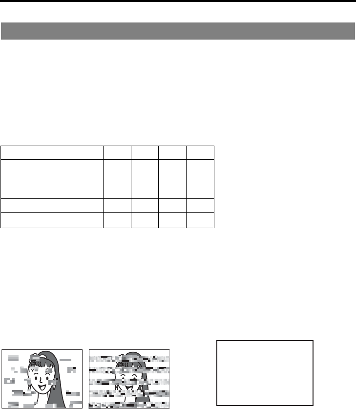
Head cleaning
• Recording or playing back with a dirty head
will result in block noise or disrupted sound.
Perform regular head cleaning to maintain
superior image and sound quality.
• For information on how to use the head
cleaning tape and the relevant remarks,
refer to Xpage 9, “Cleaning tape”.
• If the head is dusty, “HEAD CLEANING
REQUIRED!” will be displayed on the moni-
tor when this unit plays a tape.
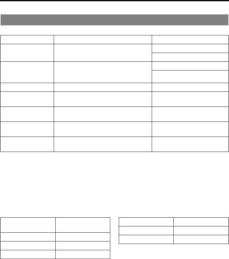
Regular maintenance
Number of hours 500H 1000H 1500H 2000H G: Cleaning, inspection and adjust-
ment
E: Cleaning and inspection; Replace-
ment if necessary
F: Replacement
Work and frequency of maintenance
depend on the environment and
usage. The above information serves
only as a guide.
Drum assembly
(including head) GEEF
Tape guide, roller GEEF
Belt gears — EEF
Drive system parts ——EF
Block Noise
HEAD CLEANING REQUIRED!
E-9
Use a JVC cleaning tape.
Follow the instructions below for using the clean-
ing tape.
1. Run the tape for 10 seconds in the PLAY
mode. (Thereafter, it stops automatically
and enters the STOP mode.)
• After loading the cleaning tape, press the
PLAY button.
2. For a single cleaning session, it can be
repeated up to 4 times.
3. Refer to the following table as a guide for
cleaning.
Note
zUnder low humidity conditions, (10% RH to
30% RH), perform head cleaning at intervals
of half of the periods stated in the table.
zIf an M-DV80 tape is used immediately after
cleaning, the message, “HEAD CLEANING
REQUIRED!” may not disappear. It does only
after the tape has run for some time.
zUse the cleaning tape at room temperature
(10°C to 35°C).
zInstructions for using the cleaning tape stated
on a sheet inside its storage case may be dif-
ferent in part from those stated here.
Follow the instructions in this manual.
•
When this unit is moved from a cold to a
warm place abruptly, the vapor in the warm
air will come into contact with the head drum
or the tape guides, which are not warmed
enough. When chilled, the vapor turns into
droplets of water. This state is known as
condensation. When condensation occurs,
the videotape adheres to the head drum or
the tape guides and will be damaged.
• Condensation occurs on this unit in the fol-
lowing circumstances:
* It is moved abruptly
from a cold place to
a warm place.
*
It is used in a place
immediately after the
heater has been turned
on, or when cold
breeze from an air-con-
ditioner blows onto it.
* It is used at a place
of high humidity.
• When condensation occurs, the monitor
displays the following warning:
Leave the unit with the power ON and wait
until the WARNING message disappears.
• Prevention of condensation
When transporting BR-HD50 from a cold to
a warmer place abruptly, first remove the
cassette tape. Then place BR-HD50 in a
plastic bag and seal it before transporting.
Take out BR-HD50 from the sealed plastic
bag only after it has the same temperature
as the surroundings.
Cleaning tape
Operating environ-
ment
Low temperature
5°C to 10°C
Room temperature
10°C to 35°C
High temperature
35°C to 40°C
Frequency of cleaning 1 to 2 times every 5
hours
1 to 2 times every 20 to
30 hours
1 to 2 times every 5
hours
Condensation
When a cassette tape is loaded, do not transport
e.g., from a cold outdoor place to a warm room thus
subjecting the unit to drastic temperature changes.
After moving the unit, do not use it until the inner
mechanism stabilizes.
Videotape
Head drum
CONDENSATION ON DRUM
E-10
NAMES AND FUNCTIONS OF PARTS
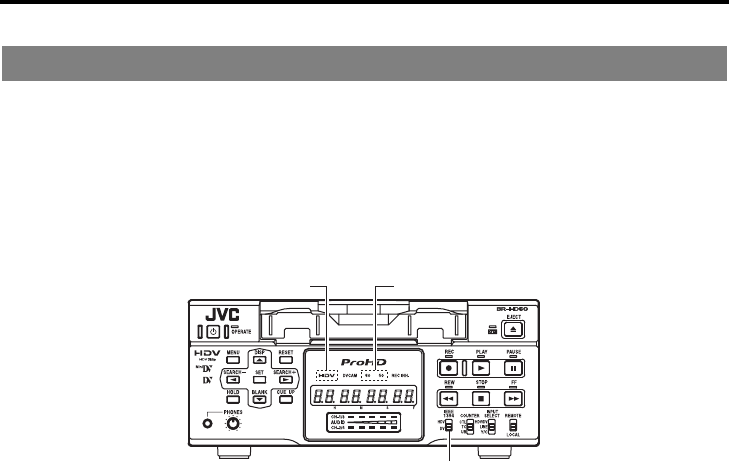
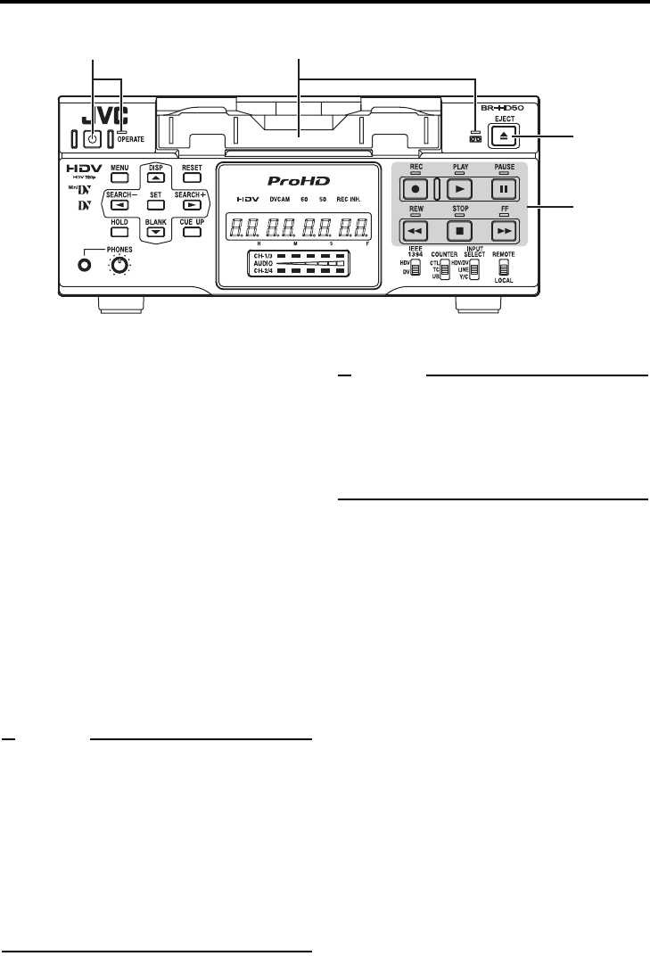
Front panel
1Cassette loading slot/LED
• For loading a cassette into or unloading it
from the slot.
Insert a standard DV cassette or a mini DV
cassette. (XPage 37)
• When BR-HD50 is in the OPERATE OFF
state and a cassette is loaded, it changes to
the OPERATE ON state.
• With a cassette loaded, the LED lights up in
green.
When a cassette is being loaded or ejected,
the LED flashes.
2[OPERATE] button/LED
•
Press this button to turn on the power and BR-
HD50 becomes ready for operation.
(OPERATE ON)
Press this button again when BR-HD50 is
already on to turn off the power. (OPERATE OFF)
• OPERATE LED lights up as follows.
OPERATE ON : the green LED lights up
OPERATE OFF : the red LED lights up
VCR error : the red LED blinks
Memo
zIf DC IN MODE in the SYSTEM [2/2] Menu
screen is set to “OPE ON”, and power is sup-
plied to the DC IN terminal on the rear panel,
power is turned on and the unit enters OPER-
ATE ON mode without pressing this button.
zEven after the power is turned off with this but-
ton, BR-HD50 is live with a small amount of
electricity.
Therefore, if BR-HD50 is not to be used for a
long period of time, please remove the AC
adapter to save energy.
3[EJECT] button
• Press this button to eject the cassette.
Memo
zIt takes about 6 seconds for the cassette to be
ejected.
zThe cassette can be ejected even when BR-
HD50 is in the OPERATE OFF mode. After the
eject action is completed, BR-HD50 returns to
the OPERATE OFF mode.
4Operation buttons
[REC] button/LED
• Hold down this button and press the PLAY
button to start recording. During recording,
the red LED lights up.
• Hold down this button and press the
PAUSE button to pause recording.
• If this button is pressed during recording, an
index signal is recorded on the tape (when
INDEX WRITE in the SYSTEM [2/2] Menu
screen is set to ON).
• When this button is pressed in the STOP
mode, the time code generator value can
be checked while the button is being held
down. If TC DUPLI. Menu is set to AUTO,
the time code, date and time of the
IEEE1394 terminal can be checked. (In DV
mode only)
21
3
4

E-11
[PLAY] button/LED
• Press this button to start playing back a
tape. During playback, the green LED lights
up.
• When recording is paused, press this but-
ton to resume recording.
[PAUSE] button/LED
• During recording, press this button to pause
it.
• In the PLAYBACK or STOP mode, press
this button to enter the STILL mode. In the
RECORDING PAUSE or STILL mode, the
green LED lights up.
• When BR-HD50 is in the STILL mode,
press this button for frame advance play-
back. (In DV mode only)
Memo
Still images or images in frame advance can be
selected with STL/F.ADV: DV of the SYSTEM [1/
2] Menu screen.
[FF] button/LED
• When BR-HD50 enters the STOP mode,
press this button to fast-forward the tape.
• When BR-HD50 is in the PLAYBACK or
STILL mode, press this button for fast-for-
ward playback. The fast forward playback
speed can be changed by pressing the
SEARCH+/S button h or the SEARCH–/
Q button (when “Q, S” KEY FUNC. in
the SYSTEM [1/2] Menu screen is set to
VAR/RECV).
(XPage 53 “Slow playback and Search
mode”)
• During fast-forwarding or fast-forward play-
back, the LED lights up in green.
[STOP] button/LED
• Press this button to stop operation.
• When BR-HD50 is in the STANDBY-OFF
mode, press this button to enter the
STANDBY-ON mode.
• While stopped, the LED lights green.
Memo
There are two stop modes.
zSTANDBY-OFF: For protecting the tape and
the drum, the drum does not rotate.
zSTANDBY-ON: The drum rotates so that it
starts up faster after BR-HD50 moves into
another mode.
[REW] button/LED
• When BR-HD50 enters the STOP mode,
press this button to rewind the tape.
• When BR-HD50 is in the PLAYBACK or
STILL mode, press this button for reverse
playback. The rewind playback speed can
be changed by pressing the SEARCH+/S
button h or the SEARCH–/Q button
(when “Q, S” KEY FUNC. in the SYS-
TEM [1/2] Menu screen is set to VAR/
RECV).
(XPage 53 “Slow playback and Search
mode”)
• During rewinding or rewind playback, the
LED lights up in green.
E-12
NAMES AND FUNCTIONS OF PARTS
Front panel (continued)
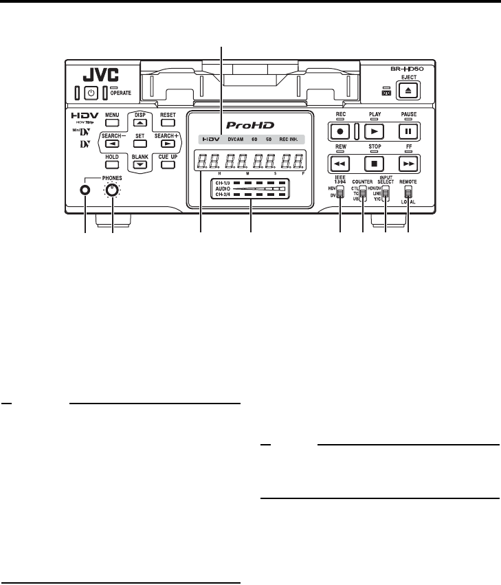
5[REMOTE/LOCAL] switch
This switch is used to select how BR-HD50 is
to be operated.
LOCAL : Use this setting if BR-HD50 is to
be controlled with the key opera-
tion of the unit.
REMOTE : Use this setting to control this unit
using the REMOTE terminal,
SERIAL REMOTE terminal, or
IEEE1394 terminal.
Memo
zSelect to enable/disable operation with the
REMOTE terminal, using REMOTE SEL 9P on
the REMOTE [1/2] Menu screen.
zTo control BR-HD50 with the SERIAL
REMOTE terminal or IEEE1394 terminal, this
switch setting can be set up with REMOTE
SEL SERIAL or REM SEL HDV/DV in the
REMOTE [1/2] Menu screen. (XPage 70)
zIf it is set to REMOTE, the buttons that can be
operated from the unit are selectable from
LOCAL FUNCTION in the REMOTE [1/2]
Menu screen.
6[INPUT SELECT] switch
This switch is used to select input signals.
HDV/DV : Inputs IEEE1394 terminal HDV sig-
nals or DV signals.
The 8 IEEE1394 switch needs to
be set, according to whether the
video format is HDV or DV.
LINE : For inputting the composite images
of the LINE IN terminal and analog
audio signals.
Y/C : For inputting the Y/C separate
video signal of the Y/C IN terminal
and analog audio signals.
Note
zSwitching is invalid during recording.
zSwitching this switch during playback may
briefly cut off the audio.
7[COUNTER] switch
Switches the displayed information on the 9
counter display and the monitor counter dis-
play.
CTL : It displays the counter in hour, minute,
second and frame based on CTL (con-
trol signal).
TC : It displays the time code data.
UB : It displays the user’s bit (UB).
567809
a
cb

E-13
8[IEEE1394] IEEE1394 terminal switch
Set this switch according to the video format of
the IEEE1394 input signal and playback sig-
nal. When the video format is HDV, a HDV
indicator is lit.
HDV : Use this setting when the video
format is HDV (HDV indicator is
lit).
DV : Use this setting when the video
format is DV (HDV indicator is off).
Note
zVideo and audio recording and playback using
the IEEE1394 terminal are unavailable when
the switch setting differs from the video format.
zWhen the IEEE1394 terminal is used to input/
output video or audio signals with a non-linear
editing system, and the format is changed by
switching this switch, either reconnect the
IEEE1394 cable, or use the OPERATE button
to reset the power.
9Counter display
Displays the counter, menu settings, and oper-
ation mode. (8 digits)
• Counter display
The displayed contents can be selected
using the 7 COUNTER switch.
• For menu settings, menu code numbers are
displayed.
0Audio level indicator
Displays the audio level for CH-1/3 and CH-2/
4.
In RECORDING mode, audio recording level
is displayed. In PLAY mode, audio playback
level is displayed.
Only the audio recording level during analog
input can be adjusted.
aIndicator lights
[HDV] indicator light
Lights when the video format for the IEEE1394
terminal input signal or playback signal is HDV.
When this indicator is lit, set the 8 IEEE1394
switch to HDV.
When this indicator is off, set the 8 IEEE1394
switch to DV.
[DVCAM] indicator light
Lights when playing a tape recorded in
DVCAM format.
Only tapes recorded in SP mode can be
played.
[60] indicator light
Lights when 60/50 SEL in the SYSTEM [2/2]
Menu screen is set to 60.
The HD signal format on this unit is set to
60Hz.
[50] indicator light
Lights when 60/50 SEL in the SYSTEM [2/2]
Menu screen is set to 50.
The HD signal format on this unit is set to
50Hz.
Memo
The field frequency for DV signals and analog
signals are fixed by region.
(U model: 60Hz, E model: 50Hz)
[REC INH] indicator light
Lights upon loading a cassette that cannot be
recorded.
b[PHONES] terminal
This is the mini jack terminal for connecting to
the headphone. (Stereo ø3.5)
• When playing back tapes recorded in 32
kHz mode, the audio channel output from
this terminal is selected using A.OUTPUT:
DV on the AUDIO Menu screen.
c[PHONES] Headphone volume
Use this switch to adjust the output level of the
PHONES terminal.
Both channels are adjusted at the same time.
E-14
NAMES AND FUNCTIONS OF PARTS
Front panel (continued)
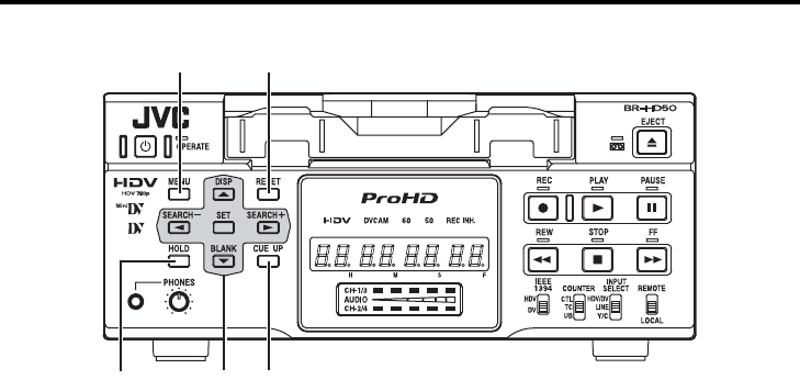
d[HOLD] button
Pressing this button while stopped will engage
the time code and user’s bit PRESET mode.
(When TCG SELECT in the TC/UB/CLOCK [1/
2] Menu screen is set to PRESET)
In time code PRESET mode, press this button
to return to the normal display.
(XPage 59 “Presetting the time code”)
e[MENU] button
If this button is pressed in the STOP/STILL
mode or when no cassette is loaded, the menu
is displayed on the monitor connected to the
video output terminal (LINE OUT, Y/C OUT,
COMPONENT OUT, or HDMI OUT terminal).
The counter display shows menu code num-
bers.
When the menu is displayed, press this button
to return to the normal display.
(XPage 64 “Setting the menus”)
f[RESET] button
• To reset the CTL counter display to “00”,
press this button.
• If this button is pressed when the time code
preset screen is displayed, all the digits of
the time code or the user’s bit are reset to
“00”.
• When the Multi Cue-up screen is displayed,
press this button to clear the registered cue-
up points.
g[CUE UP] button
When the 7 COUNTER switch is set to TC,
press this button to display the Multi Cue-up
screen on the monitor.
When the Multi-Cue-up screen is displayed,
press this button to start searching the
selected tape position.
(XPage 56 “Multi cue-up”)
hSpecial functions/Setting buttons
The following buttons have different functions
depending on whether the normal screen or
the setting screen is displayed.
Setting screens:
Menu, Date/Time setting, Time code preset
and Multi Cue-up
[DISP/R] button
• Press this button during PLAY mode to dis-
play the video output format on the counter
display.
• During the STOP or REC mode, the audio
recording level is increased. (Pressing simul-
taneously with Q or S button) (When “Q,
S” KEY FUNC. in the SYSTEM [1/2] Menu
screen is set to VAR/RECV)
(XPage 44 “Adjusting audio recording
level”)
• When the setting screen is displayed, this
button is used to select the items or setting.
fe
dhg

E-15
[BLANK/P] button
• When BR-HD50 is in the STOP mode,
press this button to start blank search. It
searches the unrecorded part of the tape
and goes into the still mode.
(XPage 54 “Blank search”)
• During the STOP or REC mode, the audio
recording level is decreased. (Pressing simul-
taneously with Q or S button) (When “Q,
S” KEY FUNC. in the SYSTEM [1/2] Menu
screen is set to VAR/RECV)
(XPage 44 “Adjusting audio recording
level”)
• When the setting screen is displayed, this
button is used to select the items or setting.
[SEARCH+/S] button
• During normal display, the function of this
button can be selected using “Q, S” KEY
FUNC. in the SYSTEM [1/2] Menu screen.
If it is set to VAR/RECV, the searching
speed increases if this button is pressed
during a search operation.
(XPage 53 “Slow playback and Search
mode”)
If it is set to INDEX, press this button to
start forward index search. This function is
not effective during recording or recording
pause.
(XPage 54 “Index search”)
• During the STOP or REC mode, CH2 is
selected as the channel for adjusting the
audio recording level. (When “Q, S” KEY
FUNC. in the SYSTEM [1/2] Menu screen is
set to VAR/RECV)
(XPage 44 “Adjusting audio recording
level”)
• When the setting screen is displayed, this
button is used to select items or setting dig-
its.
[SEARCH–/Q] button
• During normal display, the function of this
button can be selected using “Q, S” KEY
FUNC. in the SYSTEM [1/2] Menu screen.
If it is set to VAR/RECV, the searching
speed decreases if this button is pressed
during a search operation.
(XPage 53 “Slow playback and Search
mode”)
If it is set to INDEX, press this button to
start reverse index search. This function is
not effective during recording or recording
pause.
(XPage 54 “Index search”)
• During the STOP or REC mode, CH1 is
selected as the channel for adjusting the
audio recording level. (When “Q, S” KEY
FUNC. in the SYSTEM [1/2] Menu screen is
set to VAR/RECV)
(XPage 44 “Adjusting audio recording
level”)
• When the setting screen is displayed, this
button is used to return to the previous
menu or select setting digits.
[SET] button
• When the Menu screen, Date/Time setting
screen or the Multi Cue-up screen is dis-
played, press this button to confirm the set-
ting.
• In time code PRESET mode, press this but-
ton to preset the set time codes or user’s bit
to the time code generator.
E-16
NAMES AND FUNCTIONS OF PARTS
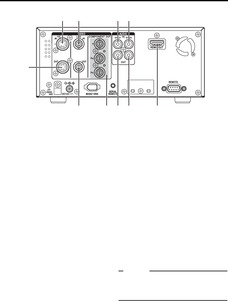
Rear panel
1[VIDEO LINE IN] terminal (BNC)
This is the input terminal for composite video
signals.
• To input video via this terminal, set the
INPUT SELECT switch located on the front
panel to “LINE”.
2[VIDEO Y/C IN] terminal (4-PIN)
This is the input terminal for Y/C separate
video signals.
• To input video via this terminal, set the
INPUT SELECT switch located on the front
panel to “Y/C”.
• When wide-screen ID signals are input, the
wide-screen ID signal is recorded.
3[VIDEO LINE OUT] terminal (BNC)
This is the output terminal for composite video
signals.
• It displays the Menu setting screen, Date/
Time setting screen and warning informa-
tion.
• If DISPLAY in the DISPLAY Menu screen is
set to “ON” or “AUTO”, information will be
displayed on-screen, e.g., the operation
mode, date/time and counter. (XPage 20)
• When the input signal or playback signal is
in HDV format, this terminal outputs video
that is converted down to 480i or 576i.
Select the style for displaying down-con-
verted video on a monitor screen with a 4:3
aspect ratio, using DOWN CONV. MODE
on the VIDEO Menu screen. (XPage 74)
4[VIDEO Y/C OUT] terminal (4-PIN)
This is the output terminal for Y/C separate
video signals.
• It displays the Menu setting screen, Date/
Time setting screen and warning informa-
tion.
• If DISPLAY in the DISPLAY Menu screen is
set to “ON” or “AUTO”, information will be
displayed on-screen, e.g., the operation
mode, date/time and counter. (XPage 20)
• When the input signal or playback signal is
in HDV format, this terminal outputs video
that is converted down to 480i or 576i.
Select the style for displaying down-con-
verted video on a monitor screen with a 4:3
aspect ratio, using DOWN CONV. MODE
on the VIDEO Menu screen. (XPage 74)
• When tapes that have recorded wide-
screen signals are played back, the wide-
screen ID signal is output.
When playing back an HDV recorded tape,
wide-screen ID signals are output according
to the mode set using DOWN CONV.
MODE in the VIDEO Menu screen.
Memo
Whether or not to enable SET UP for analog sig-
nals (composite, Y/C separate and component
signals) can be selected with SET UP [60]: DV in
the VIDEO Menu screen (for U model only).
12
4
3589 0
67

E-17
5[COMPONENT OUT] Component sig-
nal output terminal (BNC×3)
Output terminal for component video signals
(Y/PB/PR). Outputs analog HD/SD video. Con-
nect this to an HD-compatible monitor with a
COMPONENT IN terminal.
• The video format to output from this termi-
nal can be selected using OUT FORMAT
[60]/[50] in the VIDEO Menu screen.
(XPage 73, 74)
• It displays the Menu setting screen, Date/
Time setting screen and warning informa-
tion.
• If DISPLAY in the DISPLAY Menu screen is
set to “ON” or “AUTO”, information will be
displayed on-screen, e.g., the operation
mode, date/time and counter. (XPage 20)
6[CH1 AUDIO IN] terminal (RCA)
Use this terminal to input analog audio signals.
To enable audio input via this terminal, set the
INPUT SELECT switch located on the front
panel to “LINE” or “Y/C”.
Analog signals are recorded on CH1.
7[CH2 AUDIO IN] terminal (RCA)
Use this terminal to input analog audio signals.
To enable audio input via this terminal, set the
INPUT SELECT switch located on the front
panel to “LINE” or “Y/C”.
Analog signals are recorded on CH2.
8[CH1/3 AUDIO OUT] terminal (RCA)
Use this terminal to output analog audio sig-
nals.
• In the 48 kHz audio mode, it outputs the
sound of CH1.
• The output audio channel during playback
of tapes recorded in 32 kHz audio mode, or
the EE audio channel during DV signal
input in 32 kHz audio mode, can be
selected using A.OUTPUT: DV in the
AUDIO Menu screen. (XPage 72)
9[CH2/4 AUDIO OUT] terminal (RCA)
Use this terminal to output analog audio sig-
nals.
• In the 48 kHz audio mode, it outputs the
sound of CH2.
• The output audio channel during playback
of tapes recorded in 32 kHz audio mode, or
the EE audio channel during DV signal
input in 32 kHz audio mode, can be
selected using A.OUTPUT: DV in the
AUDIO Menu screen. (XPage 72)
0[HDMI OUT] HDMI signal output termi-
nal
Outputs HDMI signals. (HDMI : High Definition
Multimedia Interface)
Outputs digital HD/SD video and digital audio.
This is connected to a monitor with an HDMI
terminal.
• The video format to output from this termi-
nal can be selected using OUT FORMAT
[60]/[50] and MONITOR SELECT in the
VIDEO Menu screen. (XPage 73, 74)
• It displays the Menu setting screen, Date/
Time setting screen and warning informa-
tion.
• If DISPLAY in the DISPLAY Menu screen is
set to “ON” or “AUTO”, information will be
displayed on-screen, e.g., the operation
mode, date/time and counter. (XPage 20)
Memo
zVideo is not displayed when the connected
monitor does not support the video format
selected using OUT FORMAT [60]/[50] in the
VIDEO Menu screen.
If this occurs, set MONITOR SELECT to
HDMI[A].
zIf the monitor has a DVI-D terminal that sup-
ports HDCP, you can watch digital video by
connecting an HDMI↔DVI-D cable.
zWhen the video format of the IEEE1394 input
signal differs from the IEEE1394 switch, or
INPUT SELECT switch is set to HDV/DV and a
signal is not input into the IEEE1394 terminal,
no signal is output from the HDMI OUT termi-
nal. (“no 1394” is displayed on the counter dis-
play.) Similarly, no signal is output from the
HDMI OUT terminal when a blank cassette
tape is played. (“-------” is displayed on the
counter display.)
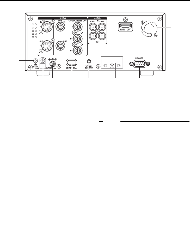
E-18
NAMES AND FUNCTIONS OF PARTS
Rear panel (continued)
a[IEEE1394] IEEE1394 terminal (6P)
This is the input/output terminal for IEEE1394-
compliant digital signals.
Inputs HDV signals or DV signals when
recording. Digital audio is input simulta-
neously.
During playback, it outputs HDV signals, DV
signals, and digital audio on the playback tape.
Upon analog signal input, EE images and EE
audio are output. EE images are DV format
signals (480i or 576i) (Only when IEEE1394
switch is set to DV).
• This unit records and plays 720p format
HDV signals.
720p HDV signals and DV signals from this
terminal are recorded as is, without format
conversion.
• To enable signal input via this terminal, set
the INPUT SELECT switch located on the
front panel to “HDV/DV”.
• The IEEE1394 switch located on the front
panel must be set to “HDV” or “DV”, accord-
ing to the input signal to this terminal or the
video format of the playback tape.
• The audio mode (48 kHz or 32 kHz) cannot
be changed for the input audio signal via
this terminal. It will be recorded using the
input signal audio mode. 4-channel record-
ing is possible in the 32 kHz audio mode.
• Power cannot be supplied via this terminal.
• To record a time code via this terminal, set
TC DUPLI. in the TC/UB/CLOCK [1/2]
Menu screen to AUTO or NONDROP.
• To control this unit via this terminal, set
REM SEL HDV/DV in the REMOTE [1/2]
Menu screen to ON or LOC/REM.
Note
When connecting the IEEE1394 cable from/to
Camcorder,VCR and other IEEE1394 device,
make sure the following instructions, otherwise
the IEEE1394 circuit device may be
destroyed.
• Turn the power of both devices OFF and
connect the IEEE1394 cable.
• Do not insert incorrectly (in reverse) the
IEEE1394 cable end to IEEE1394 port of
both devices.
• Do not connect the IEEE1394 cable under
the condition of static electricity.
• Turn the power of both devices OFF when
changing the IEEE1394 switch from/to
HDV/DV.
• If HDV/DV signals are not input/output
when the IEEE1394 cable is connected,
check whether the signal format matches
the IEEE1394 switch setting on the front
panel. If the settings match, either recon-
nect the IEEE1394 cable, or reset the
power to the unit.
habc
d
ef
g

E-19
bDC power input terminal
This terminal is for inputting DC 12 V. Connect
the DC power cord of the supplied AC adapter.
Memo
zWhen power is supplied to this terminal, the
OPERATE indicator located on the front panel
lights up. (The indicator turns red when BR-
HD50 is in the OPERATE OFF state)
zWhether to set BR-HD50 to enter the OPER-
ATE ON mode or OPERATE OFF mode when
power is supplied to the terminal can be
selected with DC IN MODE in the SYSTEM [2/
2] Menu screen.
cDC power cord clamp
Use this clamp to fasten the DC power cord.
d[SIGNAL GND] terminal
This is the grounding terminal for signals.
e[SERIAL REMOTE] terminal (mini jack)
This terminal is for connecting to the serial
remote controller.
To operate BR-HD50 with this terminal, per-
form the following settings.
• Set REMOTE SEL SER in the REMOTE [1/
2] Menu screen to “ON” or “LOC+REM”.
ON
: When the
5
REMOTE/LOCAL
switch on the front panel is set to
“REMOTE”, this terminal becomes
effective.
LOC+REM : This terminal is effective regard-
less of the setting of the 5
REMOTE/LOCAL switch on the
front panel.
Memo
To use this terminal as the foot switch input, set
FOOT SW in the REMOTE [2/2] Menu screen.
(XPage 71)
f[REMOTE] RS-422A terminal
(D-SUB 9P)
This terminal is for connecting to an RS-422A
serial interface-compatible editing remote con-
troller (e.g. RM-G820).
With this terminal, BR-HD50 can be used as a
player of an editing system.
To operate BR-HD50 with RS-422A, perform
the following settings.
• Set REMOTE SEL 9P in the REMOTE [1/2]
Menu screen to “ON”.
•Set the 5 REMOTE/LOCAL switch on the
front panel to “REMOTE”.
Memo
Screws for securing connectors differ by region.
U model : inch screws
E model : metric screws
gFan
This is a ventilation port for the fan motor.
Do not place objects in this area.
hSlot cover for servicing
This is used for servicing the unit.
E-20
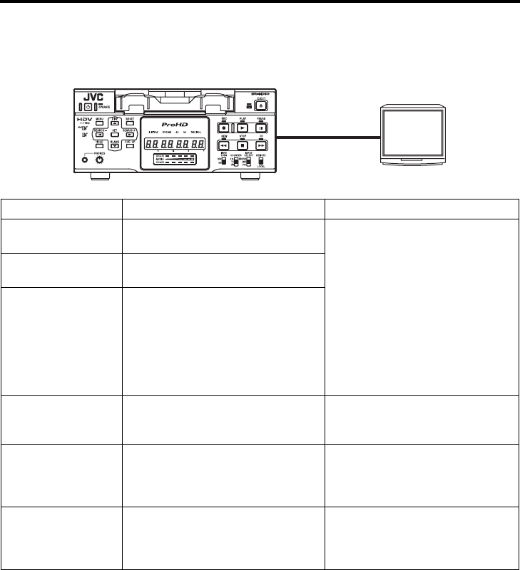
ON-SCREEN DISPLAY
On-screen display
Besides E-E images and playback images, the monitor connected to the VIDEO OUTPUT terminals
(VIDEO LINE OUT, Y/C OUT, COMPONENT OUT and HDMI OUT) provides the following on-screen
information.
On-screen display Description Operation
Status display Displays the setting status of the VCR
operation mode, date/time, counter.
Settings can be performed with DIS-
PLAY in the DISPLAY Menu screen.
ON : Always display. According to
each event or error, the event
and alarm displays are
shown for about 3 seconds.
AUTO: It displays for about 4 sec-
onds during mode changes.
OFF : No on-screen display. The
alarm display is shown
according to errors, which
occurred.
Event display Displays the operating status of blank
search, index recording/search.
Alarm display Displays error/alarm messages for
incorrect operation or improper condi-
tion of BR-HD50.
Warning display When an error occurred with the VCR,
it displays warnings with the relevant
error codes. (XPage 80)
It is displayed automatically when an
error with the VCR occurred.
Menu display Displays the menu setting screen.
(XPage 64)
When BR-HD50 enters the STOP/
STILL mode or no cassette tape is
loaded, the menu is displayed when
the MENU button is pressed.
Multi Cue-up screen Displays the Multi Cue-up screen for
registering or selecting cue-up
(searching) point. (XPage 56)
When BR-HD50 enters the STOP,
STILL or PLAY mode, press the Cue-
up button to display the Multi Cue-up
screen.
VIDEO OUTPUT
Monitor
E-21
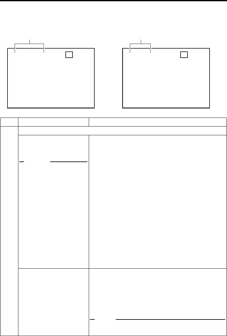
ON-SCREEN DISPLAY
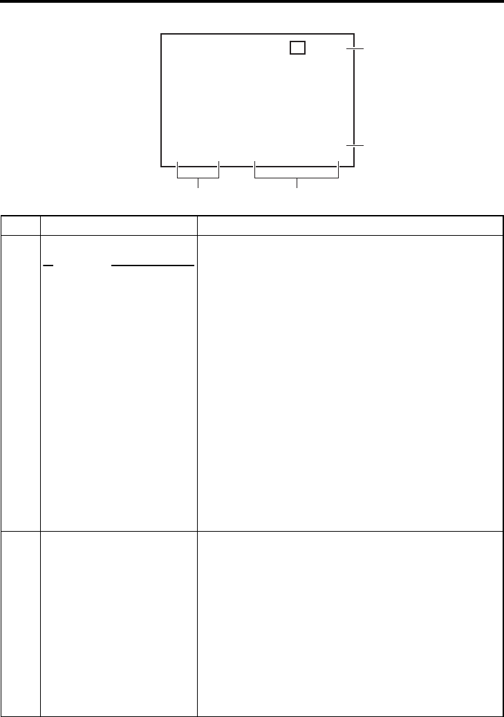
Status display
Status display: It displays the current settings and operating status.
No. Item Description
1The 1 display contents differs between DV format and HDV format.
DV format
Sampling frequency/audio
output CH
Memo
If the counter display position
is set to the upper left, this item
will be displayed on the lower
right.
•DV
Displayed when recording or playing back a tape with
video in DV format.
• Sampling frequency
While recording an analog audio signal, the setting value
of AUDIO MODE: DV in the AUDIO Menu screen is dis-
played (32 kHz or 48 kHz).
During playback, the sampling frequency of the sound
recorded on the tape is displayed (32 kHz, 48 kHz, 44.1
kHz).
During HDV/DV signal input, the sampling frequency of the
sound input is displayed.
•A.LOCK
Lights up when the video and audio sampling clocks (at 48
kHz) are synchronized in the PLAYBACK mode.
Always lights up in the RECORDING mode and EE mode.
• Audio output channel
The audio channel output from the AUDIO OUT terminal is
displayed (CH-1/2, CH-3/4, MIX). (only in 32 kHz mode)
• With A/V INFO. in the DISPLAY Menu screen, whether to
display this item can be selected.
HDV format
HDV format display
Displayed when recording or playing back a tape with video in
HDV format. HDV format details are displayed.
HDV-HD30P: 720/30p signal HDV-HD60P: 720/60p signal
HDV-HD25P: 720/25p signal HDV-HD50P: 720/50p signal
HDV-HD24P: 720/24p signal
HDV-SD60P : 480/60p signal
HDV-SD50P : 576/50p signal
Note
Does not support tapes in 576/26p mode from the GR-PD1
camera. Displays HDV-SD50p when playing back the tape.
HDV HD3 0 P–SP20
mi n
06 / 10 / 05 STANDBY
-
OFF
11:20:00 TCR 02:00:00:00
1
3DV 2K CH– 1 / 2 SP 2 0
mi n
W
ARNING 7001
DRUM MOTOR FA I LURE
REC I NH I B I T
06 / 10 / 05 STANDBY
-
OFF
11:20:00 TCR 02:00:00:00
1
DV format HDV format
E-22
ON-SCREEN DISPLAY
Status display (continued)
3DV 2K CH– 1 / 2 SP 2 0
mi n
W
ARNING 7001
DRUM MOTOR FA I LURE
REC I NH I B I T
06 / 10 / 05 STANDBY
-
OFF
11:20:00 TCR 02:00:00:00
23
4
5
No. Item Description
2Date/time
Memo
If the display position of the
counter is set to the lower left,
this item will be displayed on
the lower right.
• It displays the date and time (HR:MM:SS).
• When the unit is in the Analog/HDV Signal RECORDING
or STOP mode, it displays the data of the built-in clock.
• During playback, fast-forwarding or rewinding, the data
recorded on the tape is displayed.
• During DV signal recording, the data from the IEEE1394
terminal is displayed. If the REC button is pressed in the
STOP mode, the input data from the IEEE1394 terminal
will be displayed.
• The style for displaying the date and time can be selected
with DATE STYLE and TIME STYLE in the DISPLAY Menu
screen.
When TIME STYLE is set to 12H, the display symbols of
the hours, minutes, and days change as follows for AM
and PM.
AM = dot (.) PM = colon (:)
• Whether to display date/time and the type of display can
be selected with TIME/DATE in the DISPLAY Menu
screen.
• When the data/time is not set or when a tape is played with
no date/time data recorded, “– –” will be displayed.
3Counter display Displays the CTL counter, time code or user’s bit. The dis-
played contents can be selected using the COUNTER switch.
• CTL counter: It will be displayed if the COUNTER switch
is set to CTL. The counter shows a 7-digit
number (hour, minute, second and frame)
with + or – and “CTL” at the beginning, e.g.,
CTL-9:30:20:10
• Time code : It will be displayed if the COUNTER switch
is set to TC. The time code shows an 8-digit
number (hour, minute, second and frame).
At playback, the time codes recorded on the
tape are displayed.
The prefix indicates the time code mode.
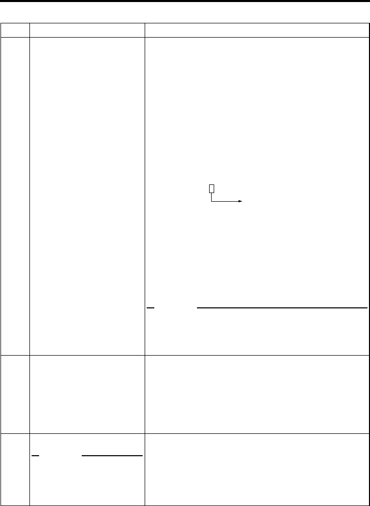
E-23
No. Item Description
When playing back an HDV recorded tape, the frame counter
of the time code is displayed according to the recorded signal
format.
720/30p…30 frame progressive
720/24p…24 frame progressive
480/60p…60 frame progressive
720/25p…25 frame progressive
576/50p…50 frame progressive
720/60p…60 frame progressive
720/50p…50 frame progressive
TCG : Time code generator data
TCR : Time code reader data
DTCG: Time code data received from the IEEE1394 terminal
(In DV mode)
Depending on the framing mode, the symbols for the seconds
and frames are different (only for NTSC).
• User’s bit : it will be displayed if the COUNTER switch
is set to UB.
The user’s bit is an 8-digit number (each
digit is a number or character from 0 – F).
The prefix indicates the user’s bit mode.
UBG : User’s bit generator data
UBR : User’s bit reader data
DUBG: User’s bit reader data received from the IEEE1394
terminal (In DV mode)
Memo
zThe position of the counter display can be changed with
COUNTER POSI in the DISPLAY Menu screen.
zThe counter display can be turned on/off with TIME CODE
in the DISPLAY Menu screen.
4VCR operation mode Displays the VCR operation mode, including:
PLAY, EJECT, FF, REW, STANDBY-ON, STANDBY-OFF,
STILL, REC, REC PAUSE, SHTL (shuttle search), JOG,
BLANK SRH (blank search), NO CASSETTE (cassette tape
not loaded), OPERATE OFF.
For SHTL and JOG, the speed is also displayed.
• The display can be turned on/off with VTR MODE in the
DISPLAY Menu screen.
5Remaining tape
Memo
If the counter display position
is set to the upper right, this
item will be displayed on the
lower right.
Displays the remaining time of tape (minutes).
Not displayed when the remaining time is being confirmed.
• The display can be turned on/off with TAPE REMAIN in the
DISPLAY Menu screen.
• The SP display disappears when a DVCAM cassette tape
is being played back.
• This remaining tape time display is only for reference.
00 : 00 : 00 : 00 Dot (.) for the drop frame mode
Colon (:) for the non-drop frame mode
E-24
ON-SCREEN DISPLAY
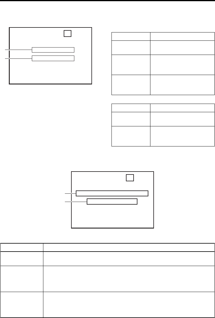
Event/Alarm display
Event display : When certain functions are in use, it is displayed at the following posi-
tions (with the DISPLAY mode ON or AUTO).
z“A” display: displayed during operation
z“B” display: displayed for about 3 seconds
Alarm display : An alarm message is displayed at the following positions when there has
been an operation error or when BR-HD50 is not in good condition, e.g.,
dirty head.
z“A” display: The state of BR-HD50 is displayed. It continues to be displayed until the error state is
corrected. This display is not affected by the setting of the display mode.
3DV 2K CH– 1 / 2 SP 2 m i n0
BLANK SEARCH
INDEX DETECTED
06 / 10 / 05 STANDBY
-
OFF
11:20:00 TCR 02:00:00:00
A
B
Display Description
BLANK
SEARCH
Blank search in progress.
INDEX +1 Index search in progress.
The number indicates the
index search position.
INDEX MARK When an index has been
specified on the tape during
recording.
Display Description
INDEX
DETECTED
An index has been detected
during index repeat operation.
VIDEO END
DETECTED
The video end has been
detected during end repeat
operation.
Display Description
LOW VOLTAGE The voltage of the DC power source is low. If the operation continues, it enters
the OPERATE OFF mode.
HEAD CLEANING
REQUIRED!
The video head is dirty. Clean it with the head-cleaning tape exclusively for BR-
HD50. (XPage 9)
If the head is clogged, it is detected in the PLAYBACK mode and this message is
displayed.
OVERHEATING! The temperature inside BR-HD50 has exceeded the stated value.
Disconnect the power and place it at a cool place. If this message is displayed
again, BR-HD50 could be defective.
Consult your JVC-authorized service agent.
3DV 2 K CH– 1 / 2 SP 2 0
mi n
HEAD CLEAN I NG REQU I RED !
NO HD VVD/SIGNAL
0 6 / 1 0 / 0 5 S T A N D B Y
-
OFF
11 : 20 : 00 TCR 02 : 00 : 00 : 00
A
B

E-25
z“B” display: Messages for incorrect operation are displayed for about 3 seconds.
They are displayed when the DISPLAY mode is ON or AUTO.
Display Description
INVALID TAPE! Data tape for PCs or DVC PRO tape is used.
The cassette tape will be automatically ejected.
LP TAPE! The user attempted to play back a tape recorded in the LP mode.
BR-HD50 cannot record or play in the LP mode.
NO HDV/DV SIG-
NAL
The user attempted to record without HDV or DV signal input.
COPY INHIBIT The user attempted to record copy-guarded signals.
REC INHIBIT The user attempted to record on a tape that is not ready for recording (the rear
switch is set to SAVE).
OPERATION
LOCK
This message is displayed when an operation button is pressed with OPERA-
TION LOCK enabled. To enable OPERATION LOCK, set OPERATION LOCK in
the SYSTEM [2/2] Menu screen to ON.
PB INHIBIT
[60/50]
This message is displayed when the HD/SD signal format setting differs during
playback of a tape recorded in HDV/DV format.
REC INHIBIT
[60/50]
• (for U model)
This message is displayed when the unit is recorded in PAL mode.
• (for E model)
This message is displayed when the unit is recorded in NTSC mode.
50/25 INHIBIT • When 60/50 SEL in the SYSTEM [2/2] Menu screen is set to 60, this message
is displayed when HDV signal format is not 60Hz.
• This message is displayed when the DV signal from the IEEE1394 terminal is
not NTSC.
60/30 INHIBIT • When 60/50 SEL in the SYSTEM [2/2] Menu screen is set to 50, this message
is displayed when HDV signal format is not 50Hz.
• This message is displayed when the DV signal from the IEEE1394 terminal is
not PAL.
E-26
CONNECTION
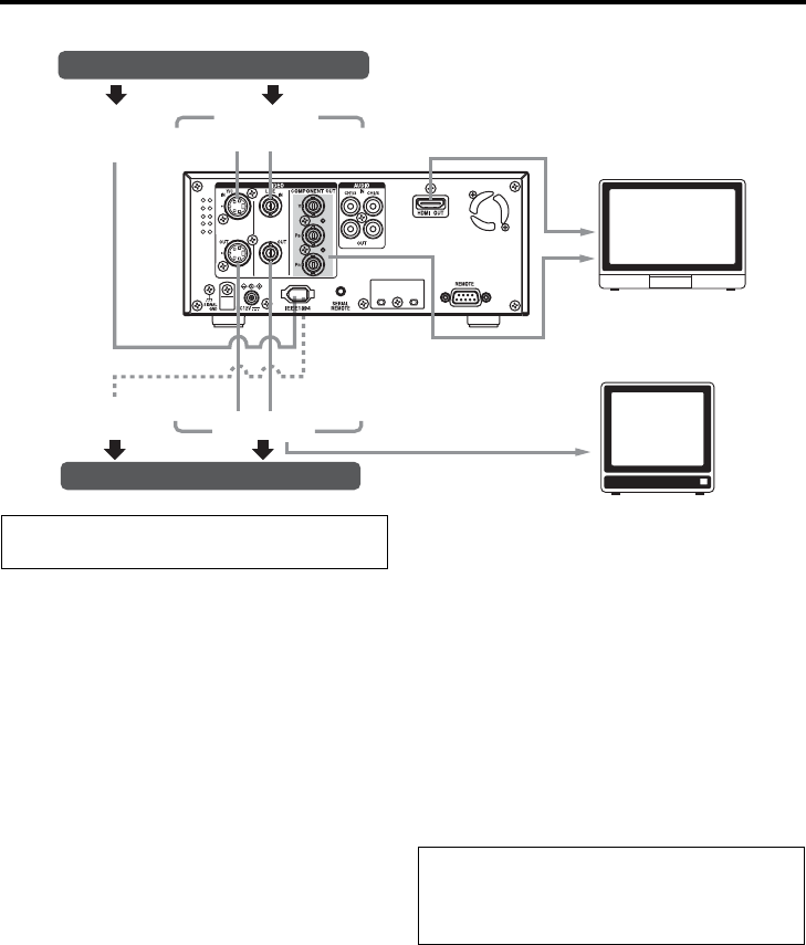
Connecting video signals
Input signal
The input video signal is selected with the
INPUT SELECT switch on the front panel.
zTo input analog video signals
Use the LINE IN terminal or Y/C IN terminal.
• LINE IN terminal:
Inputs composite video signals.
Connect a BNC cable.
• Y/C IN terminal:
Inputs Y/C separate video signals. Connect
an S video cable (4PIN).
When a wide screen ID signal is input, the
ID signal is recorded.
zTo connect digital signals
Connect HDV signals or DV signals to the
IEEE1394 terminal.
Connect an IEEE1394 (6PIN) cable.
HDV signals using 720p format can be input.
HDV 720p format:
720/60p, 720/30p, 720/24p, 480/60p
720/50p, 720/25p, 576/50p
• The IEEE1394 switch located on the front
panel needs to be set, according to whether
the video format is HDV or DV.
• Digital audio is also input from the
IEEE1394 terminal.
• Power is not supplied via the IEEE1394 ter-
minal.
Y/C
IEEE1394
HDMI OUT
Y/C
COMPONENT
OUT
Video output, e.g., VCR/Camera
Digital input
HDV/DV
Analog input
Composite HD/SD Digital
HD monitor
HD/SD Analog
Digital output
HDV/DV
Video input, e.g., VCR
Monitor
Composite
Analog output
Turn off the power before making connec-
tions.
• Attach the supplied filter to the IEEE1394
cable. (XPage 29)
• For more information on the IEEE1394 termi-
nal, refer to page 18.
E-27
Output signal
zLINE OUT terminal
Outputs composite video signals.
Connect to a monitor using a BNC cable.
In addition to the composite video signals, it
also displays the on-screen status display and
the menu settings screen.
zY/C OUT terminal
Outputs Y/C separate video signals.
Connect to a monitor using an S video cable
(4PIN).
In addition to the Y/C separate video signals, it
also displays the on-screen status display and
the menu settings screen.
When a wide screen ID signal exists in the
video signal, the ID signal is output.
zCOMPONENT OUT terminal
Outputs analog component video signals.
Connect to an HD-compatible monitor using
BNC cables (three cables).
View analog HD or SD video on the monitor.
This terminal does not output audio.
In addition to the video signals, it also displays
the on-screen status display and the menu
settings screen.
zHDMI OUT terminal
Outputs HDMI signals.
Outputs digital video and digital audio signals.
Connect to a monitor with an HDMI terminal
using an HDMI cable.
Outputs digital HD video, SD video, and digital
audio to the monitor.
When the monitor connection is a DVI termi-
nal, use an HDMI-DVI cable.
Digital HD/SD video is output to a DVI terminal
monitor. Does not output audio.
In addition to the video signals, it also displays
the on-screen status display and the menu
settings screen.
zIEEE1394 terminal
This is also an input terminal. Connect an
IEEE1394 (6PIN) cable.
Outputs HDV signals or DV signals.
Digital audio signals are output with the video.
Memo
For more information on input/output terminal
video formats, refer to pages 32 to 34.
Caution regarding video signals
zIf search images or analog video signals with
a high level of jitter are input, video or sound
may be distorted temporarily. Input stable sig-
nals, such as signals passed through a TBC.
• Attach the supplied filter to the IEEE1394
cable. (XPage 29)
• For more information on the IEEE1394 termi-
nal, refer to page 18.
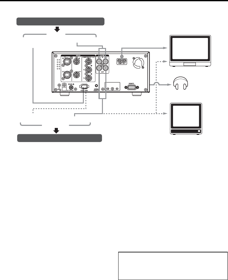
E-28
CONNECTION
Connecting audio signals
Input signal
zAnalog input
AUDIO IN terminal (RCA×2)
Connect an audio cable.
There are analog input terminals for 2 chan-
nels.
Four channels cannot be recorded simulta-
neously. Audio input from each terminal is
recorded to CH1 and CH2.
zDigital input
IEEE1394 terminal (6P)
Connect an IEEE1394 (6PIN) cable.
Inputs HDV signals or DV signals.
Digital audio signals are input with the video.
• The DV signal audio mode (48 kHz or 32
kHz) will match the input signal audio mode.
• During digital signal input, the recording
level cannot be adjusted.
Output signal
zAUDIO OUT terminal (RCA×2)
Connect an audio cable.
Analog audio is output.
For the DV format, tracks are available for 4
channels (in the 32 kHz audio mode).
• In the 32 kHz audio mode, the audio chan-
nel to output can be selected from 4 chan-
nels using A.OUTPUT: DV in the AUDIO
Menu screen.
zPHONES terminal (Stereo ø3.5)
Connect headphones.
zIEEE1394 terminal (6P)
This is also an input terminal. Connect an
IEEE1394 (6PIN) cable.
Digital audio signals are output with the video.
IEEE1394 AUDIO
OUT
AUDIO IN
HDMI OUT
Audio output, e.g., VCR/Camera
Digital audio
HDV/DV
Analog audio
HD monitor
Digital audio
HDV/DV
Audio input, e.g., VCR
Monitor
Analog audio
Analog audio
input
output
Digital audio
Headphones
• Attach the supplied filter to the IEEE1394
cable. (XPage 29)
• For more information on the IEEE1394 termi-
nal, refer to page 18.
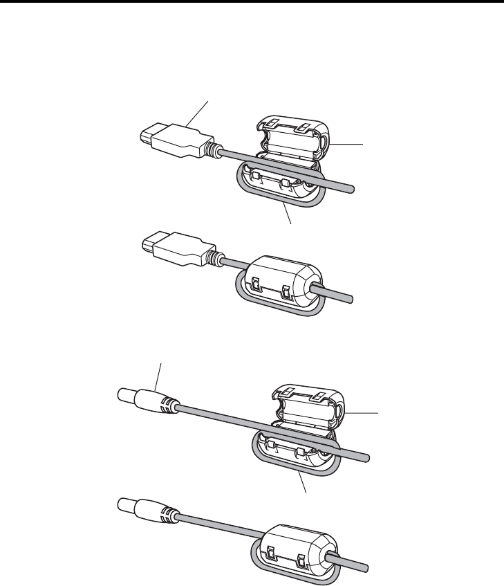
E-29
CONNECTION
Attaching the supplied ferrite core
zAlways attach the supplied ferrite core to the IEEE1394 cable and DC cord to decrease unnecessary
wave radiation.
zAttach the ferrite core close to the unit.
For BR-HD50 IEEE1394 terminal
Supplied ferrite core
Wrap the cable once around the ferrite core.
For BR-HD50 DC IN terminal
Supplied ferrite core
Wrap the cord once around the ferrite core.
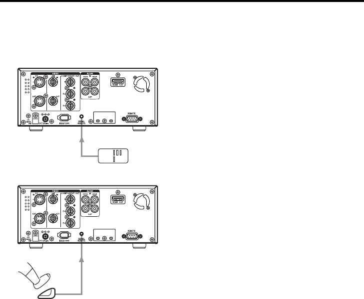
E-30
CONNECTION
Connecting with SERIAL REMOTE terminals
The following describes examples of SERIAL REMOTE terminal connection.
To use the SERIAL REMOTE terminals, set REMOTE SEL SER of the REMOTE [1/2] Menu screen
to “ON” or “LOC+REM.” (XPage 70)
Operate BR-HD50 with the wired remote controller
Connect the wired remote controller to the
SERIAL REMOTE terminal.
Start/stop recording with an external switch, e.g., a foot switch.
Connect an external switch, e.g., a foot switch,
to the SERIAL REMOTE terminal.
The format of the input signals can be selected
with FOOT SW in the REMOTE [2/2] Menu
screen. (XPage 71)
SERIAL
REMOTE Wired remote
controller
Foot
switch
SERIAL
REMOTE
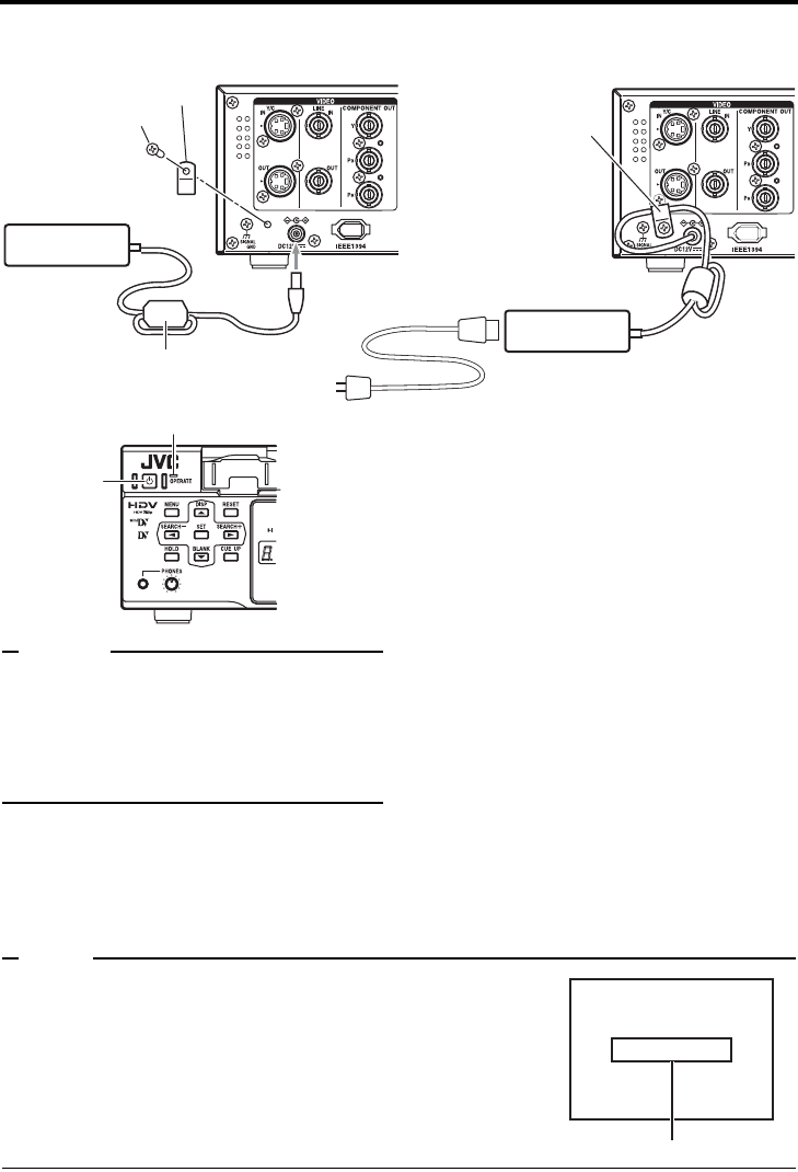
E-31
CONNECTION
Connecting the AC adapter
Connect the supplied AC adapter to BR-HD50.
Memo
zEven in the OPERATE OFF mode, a small
amount of electricity will still flow into the unit.
zWhen the unit is in the OPERATE OFF mode,
no operation can be performed except that of
the OPERATE buttons and cassette loading/
ejecting.
Always attach the supplied ferrite core
to the DC cord. (XPage 29)
1. Remove one screw on the back panel of the
unit, and remove the DC cord clamp.
2. Connect the DC cord of the AC adapter to
the DC IN terminal of BR-HD50.
3. To prevent accidental disconnection of the
DC cord, insert the DC cord into the clamp,
orient the clamp as shown in the figure
above, and secure the clamp to the unit.
Use the screw removed in step 1 above to
secure the clamp to the unit.
4. Connect the supplied power cord to the AC
IN terminal of the AC adapter.
5. Connect the power cord to the power out-
let.
• BR-HD50 is turned on and the OPERATE
indicator lights up in red.
(OPERATE OFF mode)
• If DC IN MODE of the SYSTEM [2/2] Menu
screen is set to “OPE ON”, the OPERATE
indicator will light up in green.
(OPERATE ON mode)
Note
zSupply power to BR-HD50 using the supplied AC adapter. Do not
use other power sources.
zDo not unplug the DC cord and/or the power cord during recording
or playback.
zIf the supply voltage is low, an alarm display of “LOW VOLTAGE”
is shown.
Screw
1. Clamp
Supplied AC adapter
Supplied power cord
DC cord
DC IN terminal
3. Clamp
2. 4.
5.
Supplied ferrite core
OPERATE indicator
OPERATE
button
LOW VOLTAGE
Alarm message
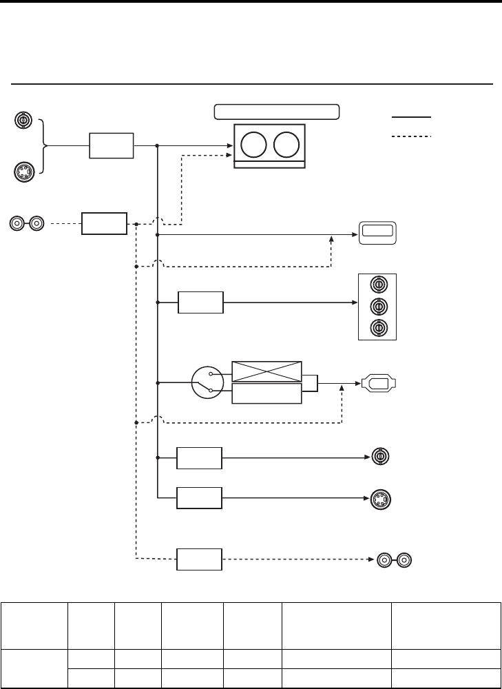
E-32
RECORDING/OUTPUT SIGNAL FORMAT
Inputting analog signal
Recording and output terminal video/audio signal format when inputting analog
signal
Input video
format Model Input
signal
Tape
recording
format
IEEE1394
terminal
HDMI OUT terminal
COMPONENT OUT
terminal
LINE OUT terminal
Y/C OUT terminal
Analog U model 480/60i 480/60i 480/60i 480/60i 480/60i
E model 576/50i 576/50i 576/50i 576/50i 576/50i
HDMI OUT
COMPONENT
OUT
Y
P
B
P
R
LINE
OUT
Y/C
OUT
LINE
IN
Y/C
IN
IEEE1394
CH 1/3 CH 2/4
AUDIO OUT
CH 1/3 CH 2/4
AUDIO IN
Front panel
IEEE1394 switch
Analog video
A/D con-
version
Digital
EE video
Input terminal Output terminal
Digital video
Tape: DV recording (480i, 576i)
Analog
audio
Digital
audio
Digital EE video
Digital EE audio
Analog EE video
Digital EE audio
Analog EE video
Analog EE video
Analog EE audio Analog audio
SD Digital video
(480i) (576i)
Digital audio
SD Analog com-
ponent video
(480i) (576i)
DV Digital video
(480i) (576i)
Digital audio
Composite
video (480i)
(576i)
Y/C separate
video (480i)
(576i)
A/D con-
version
D/A con-
version
D/A con-
version
D/A con-
version
D/A con-
version
Digital EE
audio
Video signals
Audio signals
HDV
format
DV
format
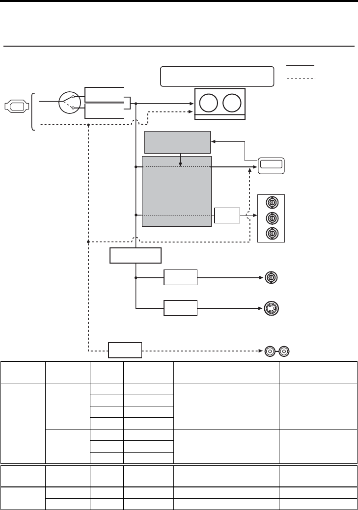
E-33
RECORDING/OUTPUT SIGNAL FORMAT
Inputting digital signal
Recording and output terminal video/audio signal format when inputting digital signal
*1 : Set using 60/50 SEL in the SYSTEM [2/2] Menu screen.
*2 : Set using OUT FORMAT [60]/OUT FORMAT [50] in the VIDEO Menu screen.
Input video
format
HD signal
format (*1)
Input
signal
Tape record-
ing format
HDMI OUT terminal
COMPONENT OUT terminal (*2)
LINE OUT terminal
Y/C OUT terminal
HDV
60Hz
720/60p 720/60p
720/60p, 480/60p, 1080/60i,
480/60i 480/60i
720/30p 720/30p
720/24p 720/24p
480/60p 480/60p
50Hz
720/50p 720/50p 720/50p, 576/50p, 1080/50i,
576/50i 576/50i720/25p 720/25p
576/50p 576/50p
Input video
format Model Input
signal
Tape record-
ing format
HDMI OUT terminal
COMPONENT OUT terminal (*2)
LINE OUT terminal
Y/C OUT terminal
DV U model 480/60i 480/60i
720/60p, 480/60p, 1080/60i, 480/60i
480/60i
E model 576/50i 576/50i
720/50p, 576/50p, 1080/50i, 576/50i
576/50i
MENU:
OUT FORMAT[60]
OUT FORMAT[50]
MONITOR SELECT
(HDMI[A]/OUT FRMT)
HDMI OUT
COMPONENT
OUT
Y
P
B
P
R
LINE
OUT
Y/C
OUT
IEEE1394
CH 1/3 CH 2/4
AUDIO OUT
Input terminal Output terminal
HDV format
Front panel
IEEE1394 switch
DV format
Tape : HDV (720p, 480p, 576p)
DV (480i, 576i) recording
Digital video
Digital
video
Digital audio
Digital audio
Digital EE audio
Analog EE video
Analog EE video
Analog EE audio
Digital EE
video
Digital EE
audio
Cross converter
(480I, 480P, 720P, 1080I)
(576I, 576P, 720P, 1080I)
HD/SD Digital video
(480i, 480p, 720p, 1080i)
(576i, 576p, 720p, 1080i)
Digital audio
HD/SD Analog compo-
nent video
(480i, 480p, 720p, 1080i)
(576i, 576p, 720p, 1080i)
Composite
video (480i)
(576i)
Y/C separate
video (480i)
(576i)
Down converter
Analog audio
D/A con-
version
D/A con-
version
D/A con-
version
D/A con-
version
Video signals
Audio signals
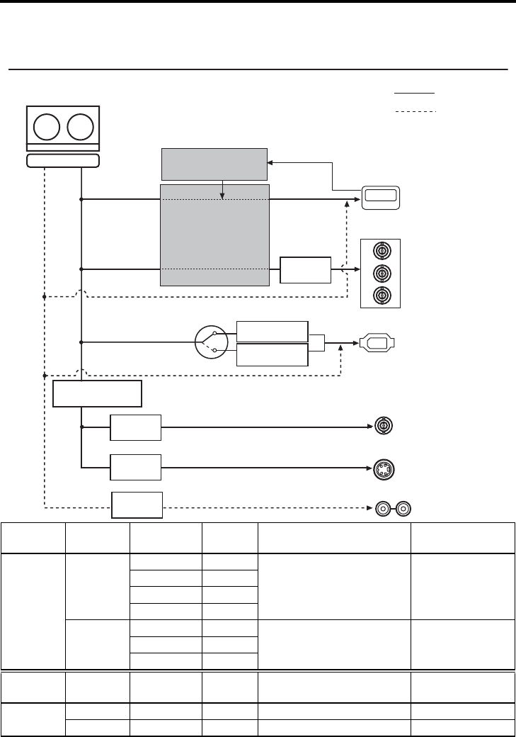
E-34
RECORDING/OUTPUT SIGNAL FORMAT
Playback
Output terminal video/audio signal format during playback
*1 : Set using 60/50 SEL in the SYSTEM [2/2] Menu screen.
*2 : Set using OUT FORMAT [60]/OUT FORMAT [50] in the VIDEO Menu screen.
Video
format
HD signal
format (*1)
Tape record-
ing format
IEEE1394
terminal
HDMI OUT terminal
COMPONENT OUT terminal (*2)
LINE OUT terminal
Y/C OUT terminal
HDV
60Hz
720/60p 720/60p
720/60p, 480/60p, 1080/60i,
480/60i 480/60i
720/30p 720/30p
720/24p 720/24p
480/60p 480/60p
50Hz
720/50p 720/50p 720/50p, 576/50p, 1080/50i,
576/50i 576/50i720/25p 720/25p
576/50p 576/50p
Video
format Model Tape record-
ing format
IEEE1394
terminal
HDMI OUT terminal
COMPONENT OUT terminal (*2)
LINE OUT terminal
Y/C OUT terminal
DV/DVCAM U model 480/60i 480/60i
720/60p, 480/60p, 1080/60i, 480/60i
480/60i
E model 576/50i 576/50i
720/50p, 576/50p, 1080/50i, 576/50i
576/50i
(480I, 480P, 720P, 1080I)
(576I, 576P, 720P, 1080I)
MENU:
OUT FORMAT[60]
OUT FORMAT[50]
MONITOR SELECT
(HDMI[A]/OUT FRMT)
HDMI OUT
COMPONENT
OUT
Y
P
B
P
R
LINE
OUT
Y/C
OUT
IEEE1394
CH 1/3 CH 2/4
AUDIO OUT
Output terminal
Video signals
Audio signals
Tape : HDV (720p, 480p, 576p)/
DV (480i, 576i)/DVCAM (480i, 576i)
format
HD/SD Digital video
(480i, 480p, 720p, 1080i)
(576i, 576p, 720p, 1080i)
Digital audio
HD/SD Analog compo-
nent video
(480i, 480p, 720p, 1080i)
(576i, 576p, 720p, 1080i)
Composite
video (480i)
(576i)
Y/C separate
video (480i)
(576i)
Analog audio
HDV (720p, 480p, 576p)
/DV (480i, 576i) Digital
video
Digital audio
D/A con-
version
D/A con-
version
D/A con-
version
D/A con-
version
Cross converter
HDV format
DV format
Down converter
Digital videoDigital
audio
Digital video
Digital audio
Digital audio
Analog audio
Analog video
Analog video
Playback
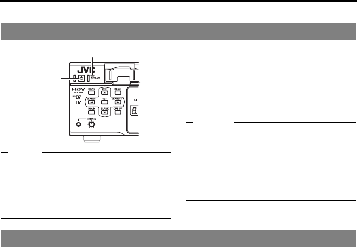
E-35
PREPARATION
Turning on/off the power
Note
After the OPERATE button is pressed and BR-
HD50 is turned on, if the green indicator blinks or
the monitor displays “UNPLUG MAIN POWER,
PLUG BACK IN AFTER A WHILE”, unplug the
power cord from the power outlet, leave it for a
while before turning on the power again.
Press the OPERATE button when BR-
HD50 is in the OPERATE OFF mode
(with the OPERATE indicator lit up in
red)
• The power is turned on and the OPERATE
indicator lights up in green. BR-HD50 is
ready for operation. (OPERATE ON mode)
Memo
zIn the OPERATE OFF mode, if a cassette tape
is inserted, the power is turned on and BR-
HD50 goes into the OPERATE ON mode.
zWhether BR-HD50 goes into the OPERATE
ON or OFF mode when the power is supplied
to the DC IN terminal can be selected with DC
IN MODE in the SYSTEM [2/2] Menu screen.
Turn off BR-HD50
1. Press the OPERATE button.
• BR-HD50 enters the OPERATE OFF mode and the OPERATE indicator lights up in red.
2. If BR-HD50 is not to be used for a long period of time, unplug the AC adapter.
To unplug the AC adapter, remove the power cord from the power outlet first.
Turning on the power
OPERATE indicator
OPERATE
button
Turning off the power
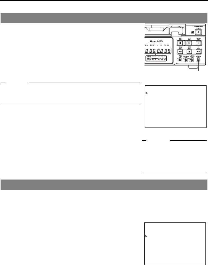
E-36
PREPARATION
Operation method (main unit/remote controller) and OPERATION LOCK mode
Whether to operate BR-HD50 with its buttons or the remote con-
troller can be selected with the REMOTE/LOCAL switch.
Setting the REMOTE/LOCAL switch
• To operate with the buttons of BR-HD50, set it to “LOCAL”.
• To operate BR-HD50 with RS-422A editing remote controller
that is connected to the REMOTE terminal, set it to
“REMOTE”.
Memo
With the REMOTE/LOCAL switch set to REMOTE, RS-422A can
be enabled using REMOTE SEL 9P in the REMOTE [1/2] Menu
screen.
• The setting position of the REMOTE switch for operating BR-
HD50 with the SERIAL REMOTE terminal can be selected
using REMOTE SEL SER in the REMOTE [1/2] Menu
screen.
• The setting position of the REMOTE switch for operating BR-
HD50 with the IEEE1394 terminal can be selected at REM
SEL HDV/DV in the REMOTE [1/2] Menu screen.
[XPage 70 “REMOTE [1/2] Menu screen”]
BR-HD50 comes with an operation lock function to prevent unauthorized or incorrect operation.
In the OPERATION LOCK mode, the operation buttons and slide switches of BR-HD50 are disabled.
However, the OPERATE ON and MENU operations are effective.
The PHONES volume is always effective.
Turning on the OPERATION LOCK mode
Set OPERATION LOCK in the SYSTEM [2/2] Menu screen to
ON.
• If the operation button of BR-HD50 is pressed while BR-
HD50 is in the OPERATION LOCK mode, “OPERATION
LOCK” is displayed on the monitor for about 3 seconds.
Turning off the OPERATION LOCK mode
Set OPERATION LOCK in the SYSTEM [2/2] Menu screen to
OFF.
Selecting the operating method (main unit/remote controller)
OPERATION LOCK mode
–––
REMOTE [ 1 / 2 ]
–––
REMOTE SE L 9P ON
REMOTE SE L SER ON
REM SEL HDV / DV ON
LOCAL FUNCT ION STP+EJT
PREROL L 7SEC
NEXT PAGE
PAGE BACK
REMOTE [1/2] Menu screen
Memo
If the REMOTE/LOCAL switch
is set to REMOTE, the buttons
that can be operated by the
main unit can be selected with
LOCAL FUNCTION.
REMOTE/LOCAL switch
–––SYSTEM[ 2 / 2 ] ––––––
DC I N MODE OPE OF F
INDEX WRITE INDEX
OPERAT I ON LOCK ON
60 / 50 SEL 60
FACTORY SETT I NG CANCEL
DRUM HOUR METER 0 0 0 0 0 0
PAGE BACK
SYSTEM [2/2] Menu screen
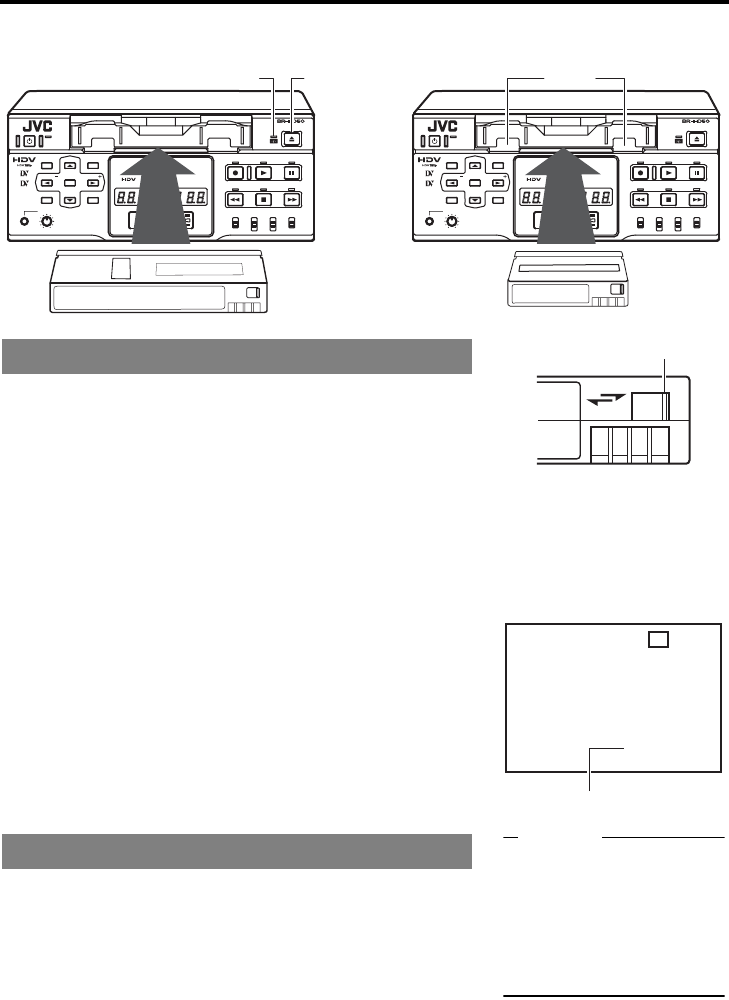
E-37
PREPARATION
Loading/Ejecting cassette
Use standard DV cassette tapes or mini DV cassette tapes.
1. Check the cassette tape.
• Setting the rear switch.
Push it to “REC” for recording.
To prevent its contents from being erased accidentally, push
it to “SAVE”.
• Ensure that the tape is not loosened.
2. Ensure that no cassette tape is loaded.
With no cassette tape loaded, the cassette LED is off.
When no cassette tape is loaded, the status display for the VCR
operation mode shows “NO CASSETTE” on the monitor.
3. Load the cassette tape.
• Insert a standard DV cassette tape into the tape-loading slot.
• For a mini DV cassette tape, load it in between the left and
right guides.
Set the tape window face up and push the cassette tape in
slowly until it is drawn in automatically.
When the cassette tape is loaded, the status display indi-
cates “STANDBY-ON”.
*
If the STANDBY-ON mode is left as is, it goes into the STANDBY-
OFF mode.
In the STANDBY-OFF mode, press the STOP button to return to
the STANDBY-ON mode.
1. Press the EJECT button of BR-HD50.
While the cassette tape is being ejected, the status display
flashes “EJECT”.
2. Remove the cassette tape.
Loading the cassette tape
Ejecting the cassette tape
OPERATE
Mini
DVCAM REC INH.
60 50
HMSF
CH-1/3
CH-2/4
AUDIO
MENU
HOLD
PHONES
BLANK CUE UP
DISP RESET REC
REW
IEEE
COUNTER
HDV
CTL
TC
UB
DV
HDV/DV
LINE
Y/C
SELECT REMOTE
LOCAL
INPUT
1394
STOP FF
PLAY PAUSE
EJECT
SEARCH SEARCH
SET
OPERATE
Mini
DVCAM REC INH.
60 50
HMSF
CH-1/3
CH-2/4
AUDIO
MENU
HOLD
PHONES
BLANK CUE UP
DISP RESET REC
REW
IEEE
COUNTER
HDV
CTL
TC
UB
DV
HDV/DV
LINE
Y/C
SELECT REMOTE
LOCAL
INPUT
1394
STOP FF
PLAY PAUSE
EJECT
SEARCH SEARCH
SET
EJECT buttonCassette LED Guide
Standard DV tape Mini DV tape
REC
SAVE
3DV 2 K CH– 1 / 2 SP 0 0M I N
06 / 10 / 05 NO CASSETTE
11:20:00 TCR 02:00:00:00
VCR mode status display
Switch
Memo
zThe cassette tape can be
loaded/ejected even when
BR-HD50 is in the OPER-
ATE OFF mode.
zThe loading/ejecting action
of the cassette tape takes
about 6 seconds.
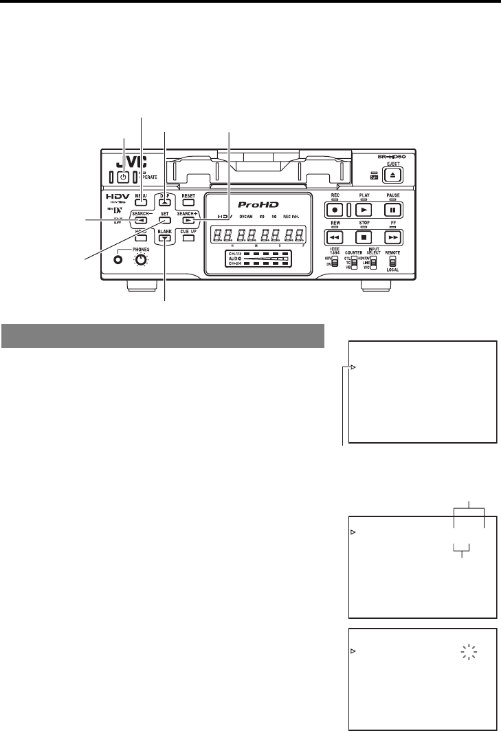
E-38
PREPARATION
Setting/Displaying date and time
This function sets up the date and time of the built-in clock. With the built-in chargeable battery, the date
and time data that have been set are maintained even after the main power is turned off. The set date
and time data are displayed on the monitor according to the settings in the Menu screen. Date and time
display information are recorded onto the tape. During IEEE1394 terminal DV signal input, internal
clock data is not recorded.
The date and time are set up at the CLOCK ADJUST Menu
screen.
The CLOCK ADJUST Menu screen is found under the TC/UB/
CLOCK [2/2] Menu.
Setting can be performed while checking the information shown on
the monitor.
Press the OPERATE button to turn on the power and
set it to the STOP mode.
1. Press the MENU button to display the TOP Menu screen.
2. Displaying the CLOCK ADJUST Menu.
1Press the R or P button to bring the cursor to the desired
TC/UB/CLOCK item. Press SET or the S button.
2Press the R or P button to bring the cursor to the NEXT
PAGE item in the TC/UB/CLOCK [1/2] Menu screen. Press
SET or the S button.
3Press the R or P button to bring the cursor to the CLOCK
ADJUST item in the TC/UB/CLOCK [2/2] Menu screen.
Press SET or the S button.
3. Setting the date and time in the CLOCK ADJUST Menu
screen.
1Press the R or P button to bring the cursor to the date or
time item. Press SET or the S button.
2Press the S or Q button to select the digit for setting.
The selected digit starts blinking.
3Press the R or P to set the value.
4Repeat step 1 – 3. After completing the required setting,
press the SET button.
Setting date and time
MENU button
R button S button
P button
Q button
OPERATE button
SET button
–––TC/UB /CLOCK [2 / 2 ] –– –
U-BIT[ 50] OFF
CLOCK ADJUST . .
PAGE BACK
–––CLO
M
CK AD JUS T– – –
D(DMD/ATE / YY ) 0 6 / 10 / 05
TIME 00:00
PAGE BACK
–––CLO
M
CK AD JUS T– – –
D(DMD/ATE / YY ) 0 6 / 10 / 05
TIME 12:00
PAGE BACK
TC/UB/CLOCK [2/2] Menu screen
CLOCK ADJUST Menu screen
Date (MM/DD/YY)...U model
Date (DD/MM/YY)...E model
Time (Hour, minute)
Cursor
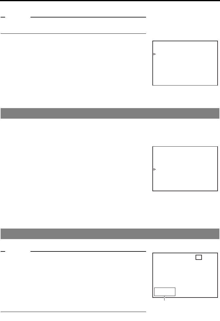
E-39
Memo
The seconds for the time cannot be set up. After the minute is set
up, press the SET button in synchronization with the time signal.
4. Returning to the TOP Menu from TC/UB/CLOCK after com-
pleting all settings
• Press the Q button.
Or
• Press the R or P button to bring the cursor to PAGE
BACK and press the SET button.
5. Returning to the usual menu
• Press the MENU button.
Or
• Bring the cursor to EXIT of the TOP Menu and press the SET
button.
The date and time data can be displayed on the monitor on-screen display (status display). Setup can
be performed at the DISPLAY Menu screen to turn on/off the date/time display and select the display
style. (For setting procedure: XPage 64)
DISPLAY Menu screen
zTIME/DATE : For enabling/disabling the display of date
and time on the status display
OFF : Does not display date/time.
TIME : Displays time only.
DATE : Displays date only.
DATE+ TM : Displays both the time and date.
zDATE STYLE : For selecting the date display style
YY/MM/DD : Year/month/day
MM/DD/YY : Month/day/year
DD/MM/YY : day/month/year
zTIME STYLE : For selecting the time display style
24H : 24-hour time mode
12H : 12-hour time mode
Set DISPLAY to ON or AUTO in the DISPLAY Menu screen.
Memo
z
In the Analog RECORDING or STOP mode : Displays the time of
the built-in clock.
zIn the PLAYBACK mode : The date and time
recorded on the
tape are displayed.
zIn the DV RECORDING mode : The date and time
from the IEEE1394
terminal are dis-
played.
Selecting date/time display
On-screen status display
–––CLO
M
CK AD JUS T– – –
D(DMD/ATE / YY ) 0 6 / 10 / 05
TIME 12:00
PAGE BACK
–––DISPLAY–––
T
DISPLAY ON
COUNTER POS I . LOWER - R
IME CODE ON
VTR MODE ON
TAP E REMA I N ON
TIME/DATE DATE+TM
A/V INFO. ON
DATE STYLE DD / MM / YY
TIME STYLE 24HOUR
PAGE BACK
DISPLAY Menu screen
3DV 2 K CH– 1 / 2 SP 0 0M I N
06 / 10 / 05 NO CASSETTE
11:20:00 TCR 02:00:00:0
0
On-screen status display
Date/time display
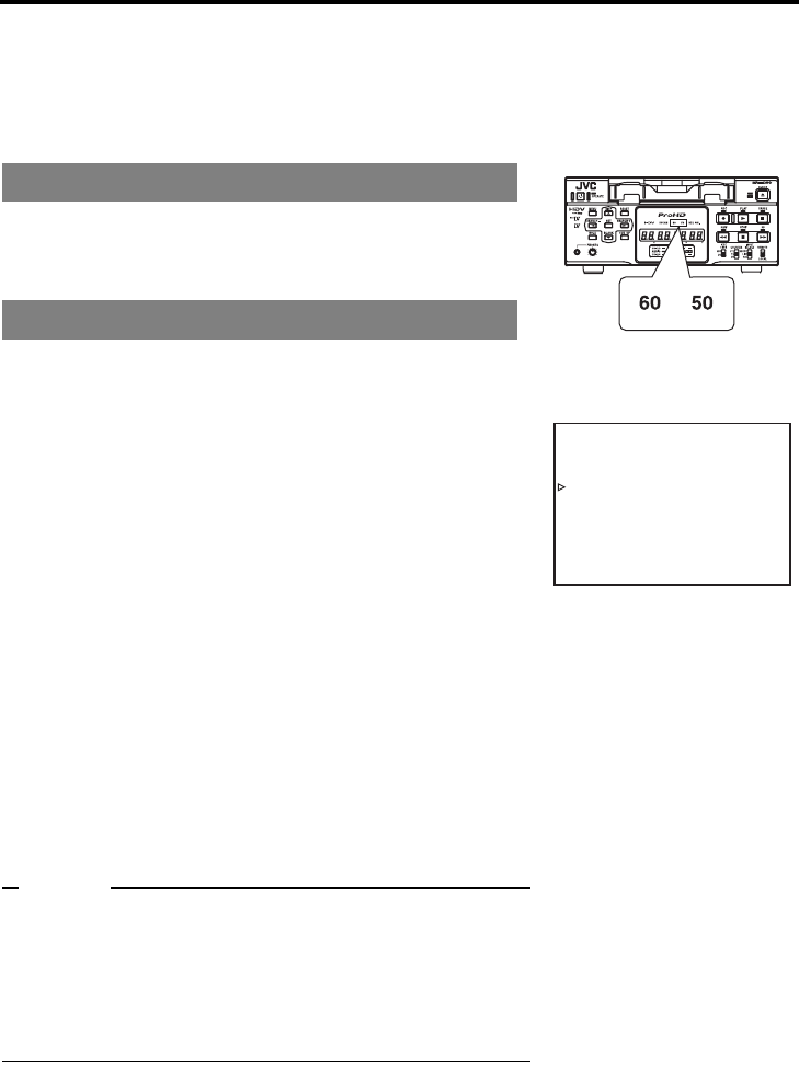
E-40
PREPARATION
Selecting HD signal format
On this unit, 60Hz format or 50Hz format for the HD signal format can be selected using 60/50 SEL in
the SYSTEM [2/2] Menu screen.
This must be set in the following situations.
zSet to match the input signal format when recording HDV signals from the IEEE1394 terminal.
zSet to match the playback signal format when playing a tape recorded with HDV signals.
Current settings on this unit can be checked by whether the front
panel 60 or 50 indicator light is lit.
60 indicator : The HD signal format is 60Hz.
50 indicator : The HD signal format is 50Hz.
Set this using 60/50 SEL in the SYSTEM [2/2] Menu screen.
Perform setting while checking the monitor display.
Press the OPERATE button to turn on the power, and
set it to the STOP mode.
1. Press the MENU button to display the TOP Menu screen.
2. Display the SYSTEM Menu screen.
Press the R or P button to move the cursor to SYSTEM,
then press SET or the S button.
3. Display the SYSTEM [2/2] Menu screen.
Press the R or P button to move the cursor to NEXT PAGE,
then press SET or the S button.
4. Set 60/50 SEL.
1Press the R or P button to move the cursor to 60/50 SEL
in the SYSTEM [2/2] Menu screen, then press SET or the S
button.
• The setting value area flashes.
2Press the R or P button to select the setting value.
60 : The HD signal format becomes 60Hz.
50 : The HD signal format becomes 50Hz.
3Press the SET or S button confirm the setting value.
The unit automatically restarts when the setting is
confirmed.
Memo
zRecording and playback are unavailable when the unit setting
differs from the HDV input signal or HDV recorded tape signal
format.
zDuring DV/analog signal input or when playing a tape recorded
with DV/analog signals, the field frequency format is fixed for
the region, regardless of the 60/50 SEL menu setting.
(U model: 60Hz, E model: 50Hz)
Check settings
Setting the Menu screen
–––SYSTEM[ 2 / 2 ] ––––––
DC I N MODE OPE OF F
INDEX WRITE INDEX
OPERAT I ON LOCK ON
60 / 50 SEL 60
FACTORY SETT I NG CANCEL
DRUM HOUR METER 0 0 0 0 0 0
PAGE BACK
SYSTEM [2/2] Menu screen
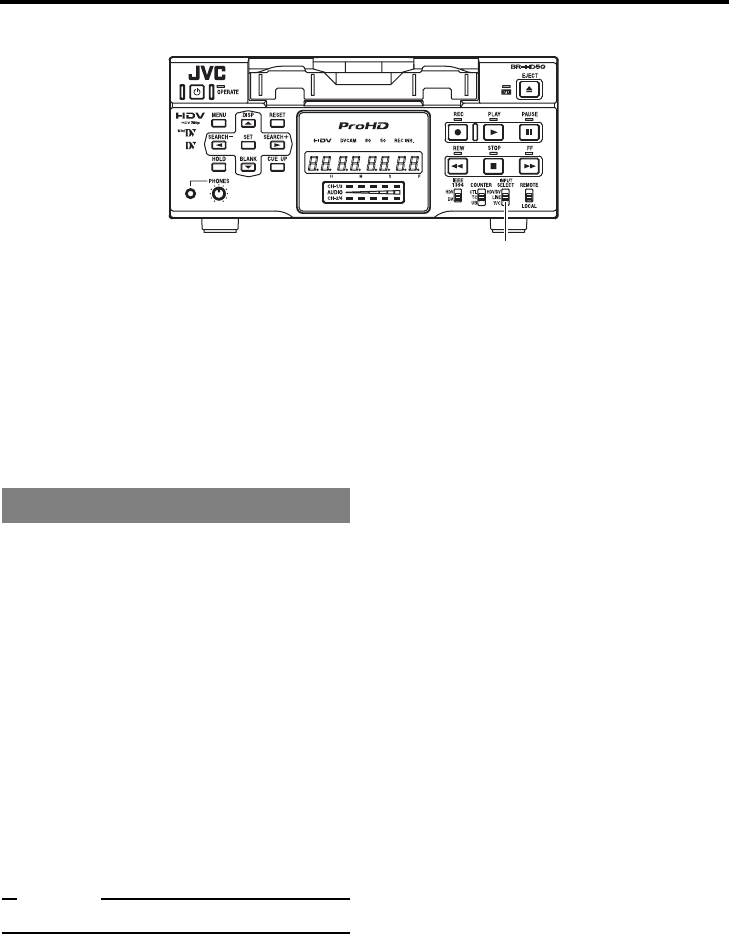
E-41
RECORDING
Settings for analog signal input
Selecting analog input signal
Set the INPUT SELECT switch located on the
front panel to LINE or Y/C.
LINE : Inputs composite video from the
LINE IN terminal, and analog audio
signals from the AUDIO IN terminal.
Y/C : Inputs Y/C separate signals from
the Y/C IN terminal, and analog
audio signals from the AUDIO IN
terminal.
Setting VIDEO Menu screen
zSET UP [60]: DV (only for U model)
Set here according to the existence of the
setup of analog video signals (composite and
Y/C separate). If it exists, set here to ON. If it
does not, OFF.
Setting AUDIO Menu screen
zAUDIO MODE: DV (In DV mode only)
Selects the audio sampling frequency for
recording.
32k : Records in 12-bit 32 kHz mode. DV
format has up to four channels of
recording tracks available, but this
unit only records onto two chan-
nels: CH1 and CH2.
48k : Records in 16-bit 48 kHz mode.
Records onto CH1 and CH2.
Memo
Audio dubbing is not available on this unit.
Setting SYSTEM Menu screen
zREC LONG P. TIME
This is for setting the time for BR-HD50 to
enter the tape protection mode if there is a
long recording pause.
zINDEX WRITE: SYSTEM [2/2] Menu
This is for selecting whether to record index
signals automatically when recording starts.
(SYSTEM menu details: XPage 67 to 69)
For settings when recording time
codes, refer to pages 60 and 61.
INPUT SELECT switch
Setting Menu screens
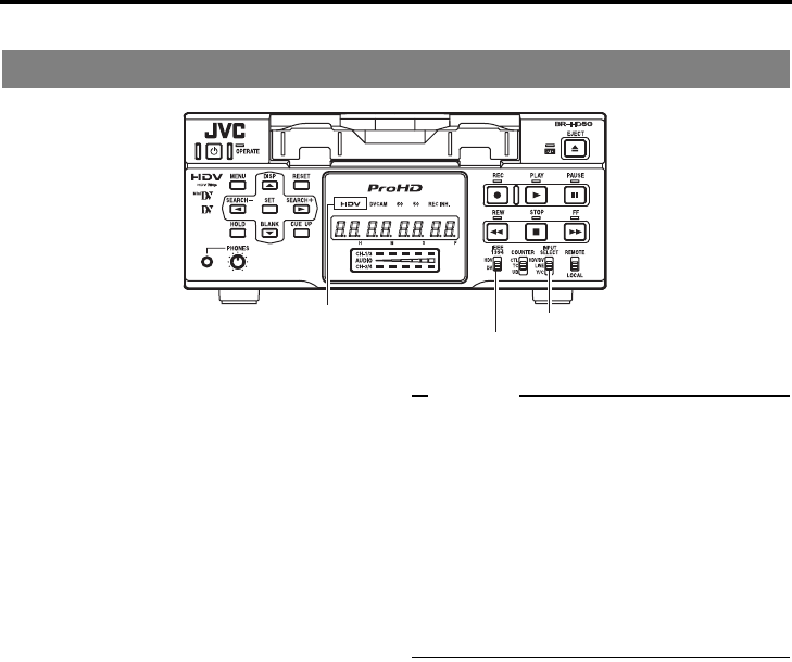
E-42
RECORDING
Settings for digital signal input
Selecting digital input signal
Set the INPUT SELECT switch located on
the front panel to HDV/DV.
Inputs IEEE1394 terminal HDV or DV digital
video.
For audio, digital audio is input from the
IEEE1394 terminal.
Settings for digital video format
Set according to whether the IEEE1394 termi-
nal input video format is HDV or DV.
Set the IEEE1394 switch on the front panel,
according to the video format of the input
signal.
HDV : To input HDV format signals, set to
this position. The HDV indicator on
the front panel will light.
DV : To input DV format signals, set to
this position. The HDV indicator on
the front panel will turn off.
Memo
zDuring digital signal input, make sure the
IEEE1394 switch setting matches the input
signal video format. When the switch setting
does not match the video format, no recording
operation is available.
zDuring HDV signal input, match the HD signal
format (60Hz or 50Hz) to the input signal for-
mat.
(XPage 40 “Selecting HD signal format”)
zRecording/output signal format during HDV or
DV signal input: XPage 33
Selecting input signal
IEEE1394 switch
INPUT SELECT switch
HDV indicator light

E-43
Setting SYSTEM Menu screen
zREC LONG P. TIME
This is for setting the time for BR-HD50 to
enter the tape protection mode if there is a
long recording pause.
zINDEX WRITE: SYSTEM [2/2] Menu
This is for selecting whether to record index
signals automatically when recording starts.
(SYSTEM menu details: XPage 67 to 69)
Setting VIDEO Menu screen
zOUT FORMAT [60]/[50]
Select the EE image format output from the
HDMI OUT terminal and the COMPONENT
OUT terminal. (Cross converter video)
Setting [60]: NATIVE/480I/480P/1080I/720P
Setting [50]: NATIVE/576I/576P/1080I/720P
zMONITOR SELECT
To automatically match the EE image format
output from the HDMI terminal to the video for-
mat of the connected display, set this menu
item to HDMI[A].
[Settings: HDMI[A]/OUT FRMT]
zDOWN CONV. MODE
The HDV signal is a wide-screen video signal.
When HDV signals are input, the output from
the LINE OUT terminal and Y/C OUT terminal
will be down-converted EE images (480i/576i).
Set the style for displaying the down-con-
verted EE image on a display with a 4:3 aspect
ratio.
This will also apply to down-converted EE
images (480i/576i) output from the COMPO-
NENT OUT terminal.
[Settings: SQUEEZE/LETTER BOX/SIDE-
CUT]
zUP CONV. MODE
Up-converts DV input signals or DV/DVCAM
recorded tape playback signals, and sets the
video mode for output from the COMPONENT
OUT terminal.
[Settings: FULL/SIDE P.]
(VIDEO menu details: XPage 73 to 75)
Settings for recording the time code
Select the time code to record, from the data in
the built-in time code generator or from the time
code data input from the IEEE1394 terminal,
using TC DUPLI. in the TC/UB/CLOCK [1/2]
Menu screen. To record the time code from the
IEEE1394 terminal, set TC DUPLI. to AUTO or
NON DROP.
(Setting time code recording: XPage 60, 61)
Memo
zAudio mode
During digital signal input, the audio mode is
identical to the IEEE1394 terminal input signal
mode.
DV format : 48K, 44.1K, or 32K mode
HDV format : 48K mode
During digital signal input, the AUDIO MODE:
DV setting in the AUDIO menu is invalid.
zTime/Date display
During DV signal input, data from the built-in
clock cannot be recorded.
The date/time data input from the IEEE1394
terminal is recorded, regardless of the menu
settings.
Setting related Menu screen
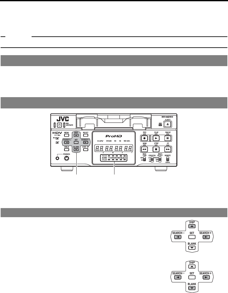
E-44
RECORDING
Adjusting audio recording level
The analog audio recording level can be adjusted on this unit. There are two adjustment methods,
selected using A.REC VR.MD.: DV in the AUDIO Menu screen.
The audio recording level can be set to the initial setting value. (UNITY mode)
Memo
Audio input level from the IEEE1394 terminal cannot be adjusted.
Set “Q, S” KEY FUNC. in the SYSTEM [1/2] Menu screen to VAR/RECV.
Select an adjustment method using A.REC VR.MD.: DV in the AUDIO Menu screen.
BOTH : The audio recording level for both CH1 and CH2 are adjusted simultaneously.
INDEPEND : The audio recording level for CH1 and CH2 are adjusted separately.
Hide the Menu screen.
This can be adjusted in the STOP or REC mode. Watching the audio level indicator
on the front panel, adjust so that the far right LED is turned off.
Increasing the recording level
Press the R button while holding down the Q or S button. The
audio recording level for both CH1 and CH2 increases.
Decreasing the recording level
Press the P button while holding down the Q or S button. The
audio recording level for CH1 and CH2 decreases.
Settings
Adjusting audio recording level
Simultaneously adjusting both channels (BOTH)
Adjustment buttons Audio level indicator

E-45
Adjusting the CH1 channel
Press the R or P button while holding down the Q button.
Press the R button to increase the recording level.
Press the P button to decrease the recording level.
Adjusting the CH2 channel
Press the R or P button while holding down the S button.
Press the R button to increase the recording level.
Press the P button to decrease the recording level.
To set the audio recording level to the initial setting
value, press the Q button and S button simulta-
neously.
• The audio recording level is fixed to the initial setting value.
Adjusting each channel separately (INDEPEND)
Adjusting the audio recording level to the initial setting value
(UNITY mode)
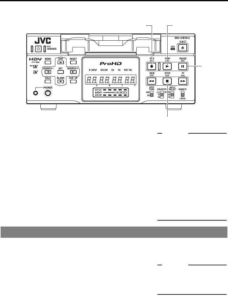
E-46
RECORDING
Recording procedure
1. Load the cassette tape.
• Before loading the cassette tape, please ensure that the rear
slide of the cassette tape is pushed to REC.
The unit is turned on.
2. Start recording.
• Press the PLAY button while holding down the REC button.
3. Pause recording.
• Press the PAUSE button.
4. Resume recording.
• Press the PLAY button.
5. Stop recording.
• Press the STOP button.
If INDEX WRITE is set to ON in the SYSTEM [2/2] Menu screen, an index signal is recorded at the
recording starting position of the tape. In the PLAYBACK mode, the position where the index signal is
recorded can be searched. (Index search)
Press the REC button to record index signals during
recording.
* It is not possible to record only index signals after the record-
ing. Allow at least an interval of 1 minute between recordings
of index.
* Index signals cannot be recorded with the REC button of the
remote controller. Use the record button of BR-HD50.
2. REC button
5. STOP button
3. PAUSE
button
2. 4. PLAY button
Memo
zThe tape protection function
enables BR-HD50 automati-
cally to go into the STOP
mode when there is a long
recording pause. The time to
go into the STOP mode can
be set with REC LONG P.
TIME in the SYSTEM [1/2]
Menu screen.
zWhen a home-use DV VCR
is used to play tapes record-
ed with BR-HD50, the sound
level may be reduced.
Recording index signals
Memo
If recording is performed right
after the RECORDING PAUSE
mode is exited, index signals
are not recorded.
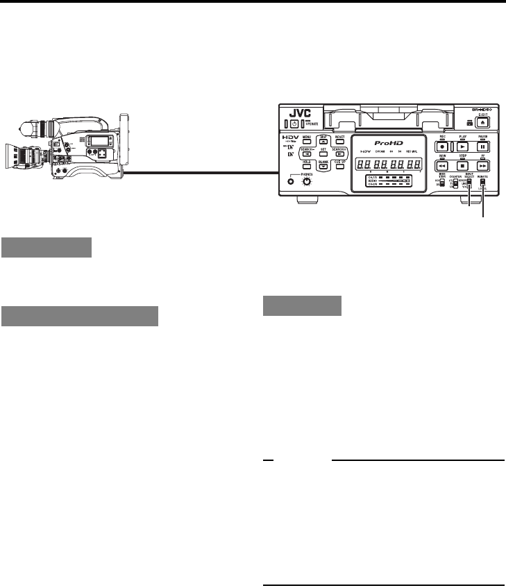
E-47
RECORDING
Backup recording function
In combination with DV equipment, BR-HD50 can perform continuous, long-hour recording.
BR-HD50 can be set as the backup unit connected to a DVcamcorder (GY-DV300/DV500/DV550/
DV5000, etc.). When the recording tape of the source unit nears its end, BR-HD50 can start recording,
enabling long-hour recording.
Connect the DV terminal of the source unit to the
IEEE1394 terminal of BR-HD50 with an IEEE1394
cable.
Set the INPUT SELECT switch on the
front panel to “HDV/DV”.
Set the REMOTE/LOCAL switch on the
front panel to “REMOTE”.
Set BACKUP REC: DV in the SYSTEM
[1/2] Menu screen.
Use the following settings according to the
tape length of the source unit.
* For DV or mini DV cassette tape:
25MIN : 30-minute tape
55MIN : 60-minute tape
75MIN : 80-minute tape
115MIN : 120-minute tape
175MIN : 180-minute tape
265MIN : 270-minute tape
OFF : No backup recording
Set the REM SEL HDV/DV in the RE-
MOTE [1/2] Menu screen to ON or
LOC+REM.
Set TC DUPLI. in the TC/UB/CLOCK [1/2]
Menu screen to OFF.
• It records the data of the built-in time code
generator.
• When TC DUPLI. is set to AUTO or NON
DROP, the time code of the DV camcorder
will stop advancing. If the DV cable is dis-
connected, the time code of the backup
recording will stop advancing.
For using GY-DV5000/DV5100 as the
source unit
Set DV REC TRIGGER in the OTHERS [1/2]
Menu screen of GY-DV5000/DV5100 to OFF.
1. Recording begins on the source unit.
* Ensure that recording starts from the begin-
ning of the recording tape.
2. BR-HD50 begins recording when the tape of
the source unit nears its end (about 5 min-
utes before the end of the tape).
• BR-HD50 begins recording when the record-
ing time of the source unit reaches the time
set by BACKUP REC: DV.
Memo
zIn backup recording, BR-HD50 records video/
sound from the source unit.
While this unit is performing backup recording,
continue shooting from the source unit.
zThe audio mode is the one selected in the
source unit. (32 K/48 K)
zSet BACKUP REC: DV to “OFF” if the unit is
not performing backup recording.
Backup unit: BR-HD50
IEEE1394
terminal
DV terminal
IEEE1394 cable
REMOTE/LOCAL switch
INPUT SELECT switch
Connection
Setting up BR-HD50 Operation

E-48
RECORDING
Recording with SERIAL REMOTE terminals
Recording can be turned ON/OFF with a serial remote controller or foot switch connected to the serial
remote terminal located at the rear panel of BR-HD50.
The serial remote controller can be connected to the SERIAL
REMOTE terminal located on the rear panel of BR-HD50.
To use the SERIAL REMOTE terminal, set REMOTE
SEL SER in the REMOTE [1/2] Menu screen to ON or
LOC+REM. Then, set the REMOTE/LOCAL switch on
the front panel accordingly.
zREMOTE SEL SER
ON : When the REMOTE/LOCAL switch is set to
REMOTE, operations can be performed via the
SERIAL REMOTE terminal.
LOC+REM : With the REMOTE/LOCAL switch is set either way,
operations can be performed via the SERIAL
REMOTE terminal. With this setting, the buttons
and switches of the unit can be used too.
Set FOOT SW in the REMOTE [2/2] Menu screen accord-
ing to how the SERIAL REMOTE terminal is used.
OFF : Set to OFF when the serial remote controller is
used. The footswitch cannot be used.
L EDGE : Recording and recording pause is switched at the
LOW edge of the footswitch signal.
H EDGE : Recording and recording pause is switched at the
HIGH edge of the footswitch signal.
L LEVEL : Recording is performed at the LOW edge and
paused at the HIGH edge of the footswitch signal.
Before using the foot switch, set BR-HD50 to the RECORDING or
RECORDING PAUSE mode using the relevant buttons of the unit.
(Only with L EDGE and H EDGE)
Memo
zThe foot switch can only be used to switch between RECORD-
ING ON and OFF.
zThe foot switch can be operated regardless of the setting of the
REMOTE/LOCAL switch.
Connection
Setting
Operation
REMOTE/LOCAL switch
SERIAL
REMOTE
• Serial remote controller
• Foot switch
–––
REMOTE [ 1 / 2 ]
–––
REMOTE SE L 9P ON
REMOTE SE L SER ON
REM SEL HDV / DV ON
LOCAL FUNCT ION STP+EJT
PREROL L 7SEC
NEXT PAGE
PAGE BACK
–––REMOTE[2/2]–––
REM FF / REW MODE FF / REW
REM STOP SE L . EE
PB START DELAY 0 F
SYNCHRON I ZAT I ON ON
CONT ROL L E R SE L T YP E 1
FOOT SW L EDGE
PAGE BACK
Foot switch
Serial IN
H
400ms
L
Memo
zBesides recording, the serial
remote controller can per-
form other functions.
z
If the REMOTE SEL SER is set
to ON, unit buttons that can be
operated can be selected from
LOCAL FUNCTION in the
REMOTE [1/2] Menu screen.
REMOTE
[1/2]
M
enu screen
REMOTE [2/2] Menu screen
terminal
Signal
Min
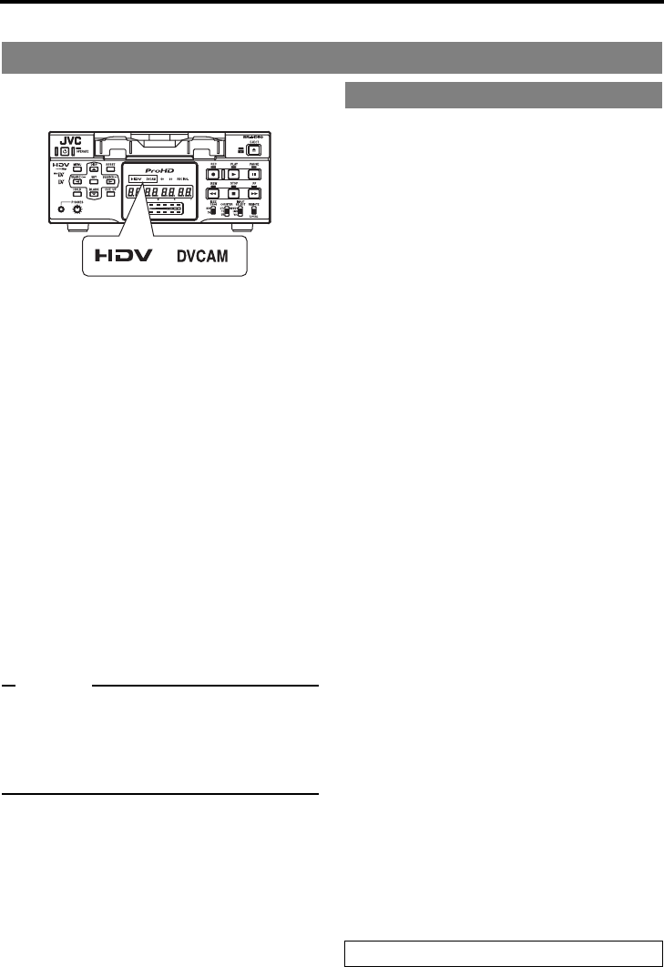
E-49
PLAYBACK
Playback settings
This unit plays back tapes recorded in HDV, DV,
or DVCAM format. (SP mode only)
When playing back tapes recorded in HDV or
DVCAM format, the front panel HDV or DVCAM
indicator is lit.
Selecting playback video format
Set whether to automatically detect the video
format for playback, or to select a specific for-
mat, using PB TAPE FORMAT on the SYS-
TEM [2/2] Menu screen.
[Settings: AUTO, DV, HDV, DVCAM]
(Details: XPage 69)
Setting IEEE1394 terminal output
video format
Set the IEEE1394 terminal output video format
to HDV or DV.
Set the IEEE1394 switch on the front panel,
according to the playback video format.
HDV : Use this setting when the playback tape
video format is HDV.
DV : Use this setting when the playback tape
video format is DV or DVCAM.
Memo
zWhen playing back a tape recorded in HDV
format, match the unit HD signal format (60Hz
or 50Hz) to the playback signal format.
(XPage 40 “Selecting HD signal format”)
zPlayback output signal format: XPage 34
Selecting video format for HDMI OUT
terminal and COMPONENT OUT terminal
zOUT FORMAT [60]/[50]
Select the playback image format to output
from the HDMI OUT terminal and the COMPO-
NENT OUT terminal. (Cross converter video)
[Settings [60]: NATIVE, 480I, 480P, 1080I, 720P]
[Settings [50]: NATIVE, 576I, 576P, 1080I, 720P]
Automatic selection of HDMI OUT ter-
minal video output
zMONITOR SELECT
To automatically match the playback image
format output from the HDMI OUT terminal to
the video format of the connected display, set
this menu item to HDMI[A].
[Settings: HDMI[A]/OUT FRMT]
Screen display style for up/down-con-
verter video
zDOWN CONV. MODE
The HDV signal is a wide-screen video signal.
When playing a tape recorded in HDV format,
the output from the LINE OUT terminal and Y/
C OUT terminal will be down-converted play-
back images (480i/576i).
Set the style for displaying the down-con-
verted playback image on a display with a 4:3
aspect ratio.
This will also apply to down-converted play-
back images (480i/576i) output from the COM-
PONENT OUT terminal.
[Settings: SQUEEZE/LETTER BOX/SIDECUT]
zUP CONV. MODE
Up-converts DV/DVCAM recorded tape play-
back signals, and sets the video mode for out-
put from the COMPONENT OUT terminal.
[Settings: FULL/SIDE P.]
Setting analog signal setup (U model
only)
zSET UP [60]: DV
Set enabling or disabling the application of set-
ups to analog video signals (composite, Y/C
separate, and SD component).
Video settings
Setting VIDEO Menu screen
VIDEO menu details: XPage 73 to 75

E-50
PLAYBACK
Playback settings (continued)
Set audio settings using the AUDIO Menu
screen.
Selecting output audio channel (DV
only)
zA.OUTPUT: DV
To play back tapes recorded in the 32 kHz
mode, select the output audio channel for the
AUDIO OUT terminal or the PHONES termi-
nal. In the 48 kHz mode or HDV format, the
audio of CH1 and CH2 is output regardless of
the setting of this menu item.
[Settings: CH-1/2, MIX, CH-3/4]
Selecting audio output during search
(DV only)
zA. OUT AT SRH: DV
For selecting whether sound is output during
variable speed playback. In HDV format, audio
is not output during search, regardless of the
setting of this menu item.
[Settings: ON, OFF]
Selecting the standard audio output
level
zAUDIO OUT LEVEL
Select the standard audio output level.
Set to –12dB to playback tapes recorded at
–12dB on a home-use DV machine.
[Settings: –20dB, –12dB]
Selecting V. fade function (DV only)
zV.FADE: DV
Select whether to fade the audio during play-
back at jointed portions of recording. No fading
occurs for HDV format.
[Settings: OFF, ON]
Set various functions in the SYSTEM Menu
screen.
Selecting still pictures or frame-
advance playback (DV only)
zSTL/F.ADV: DV
Selects still pictures or frame-advance play-
back when playing back DV format video.
[Settings : FIELD, 1ST FIELD, 2ND FIELD,
FRAME]
When playing back HDV format video, frame
images are output, regardless of the setting of
this menu item.
Selecting still mode
zLONG PAUSE TIME
For setting the time (minute) when BR-HD50
enters the tape protection mode if BR-HD50 is
in the STILL mode for a long time.
[Settings: 5, 3, 2, 1 minute or 30 seconds]
zLONG PAUSE MODE
For selecting the state of BR-HD50 when it
enters the tape protection mode after it stayed
in the STILL mode for a prolonged period of
time.
[Settings: F.ADV or STBY-OFF]
Selecting Q, S button functions
z“Q, S” KEY FUNC.
Select whether to use the SEARCH+ (S) and
SEARCH– (Q) buttons for index search, or to
change the search speed.
[Settings : INDEX, VAR/RECV]
Selecting repeat playback function
zREPEAT MODE
This mode is for turning ON/OFF the REPEAT
PLAYBACK function and selecting the type of
REPEAT PLAYBACK. If REPEAT PLAYBACK
is not performed, set it to OFF.
[Settings: OFF, INDEX, V. END, TAPE END]
Audio settings
Setting AUDIO Menu screen
Settings regarding playback
function
Setting SYSTEM Menu screen
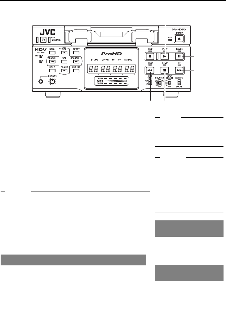
E-51
PLAYBACK
Basic playback procedure
1. Load a recorded cassette tape.
The power for BR-HD50 is turned on.
2. Start playback.
Press the PLAY button.
Playback starts.
When playing back tapes recorded in HDV format, the front
panel HDV indicator is lit.
When the tape is recorded in DVCAM format, the DVCAM
indicator is lit.
3. Pause the tape.
Press the PAUSE button.
A still image is output.
Memo
The still image selected with STL/F.ADV: DV in the SYSTEM [1/2]
Menu screen is output. (1st field image/ 2nd field image/ frame
image)
Playback of HDV format tapes is always in frame image output.
4. Resume playback.
Press the PLAY button.
5. Stop playback.
Press the STOP button.
When BR-HD50 is in the STOP mode, press the FF
button to fast-forward the tape.
When BR-HD50 is in the STOP mode, press the REW
button to rewind the tape.
Fast forward/rewind
PLAY button
PAUSE button
FF button
STOP buttonREW button
Note
Tapes recorded in the LP mode
cannot be played. The monitor
displays an alarm message:
“LP TAPE!”
Memo
zPress the DISPLAY button
during PLAY mode to dis-
play the playback video for-
mat on the counter display.
zWhen output of still image
continues for a prolonged
period, BR-HD50 enters the
tape protection mode.
Set 60/50 SEL in the SYSTEM
[2/2] Menu screen, according
to the HD signal format. (60Hz
or 50Hz)
To use the IEEE1394 terminal
output signal, set the front
panel IEEE1394 switch accord-
ing to the video format of the
playback tape. (HDV or DV)
Playback of tapes recorded
in HDV format
IEEE1394 terminal output
signal
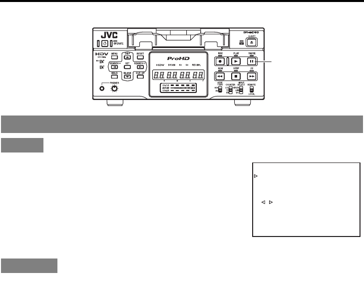
E-52
PLAYBACK
Special playback functions
STL/F. ADV: DV in the SYSTEM [1/2] Menu screen
The unit of frame advance and still images can be selected. (DV
format only)
FIELD : Field-by-field advance
1st FIELD : Frame-by-frame advance and stops at the 1st
field.
2nd FIELD : Frame-by-frame advance and stops at the 2nd
field.
FRAME : Frame-by-frame advance.
• Does not frame-advance when playing back an HDV tape.
1. Set BR-HD50 to the STILL mode.
2. Press the PAUSE button to perform frame advance.
Frame-advance playback
Setting
Operation
PAUSE button
KCABEGAP
EGAPTXEN
FFOEDOMTAEPER
VCER/RAV.CNUFYEK”,“
FFFO
-
YBT
S
EDOMESUAPGNOL
CES30EMITESUAPGNOL
FFOVD:CER
NI5MEMIT.P GNO LCER
PUKCAB
DN
2
VD:VDA.F/LTS
–––]2/1[METSYS––
–
SYSTEM [1/2] Menu screen
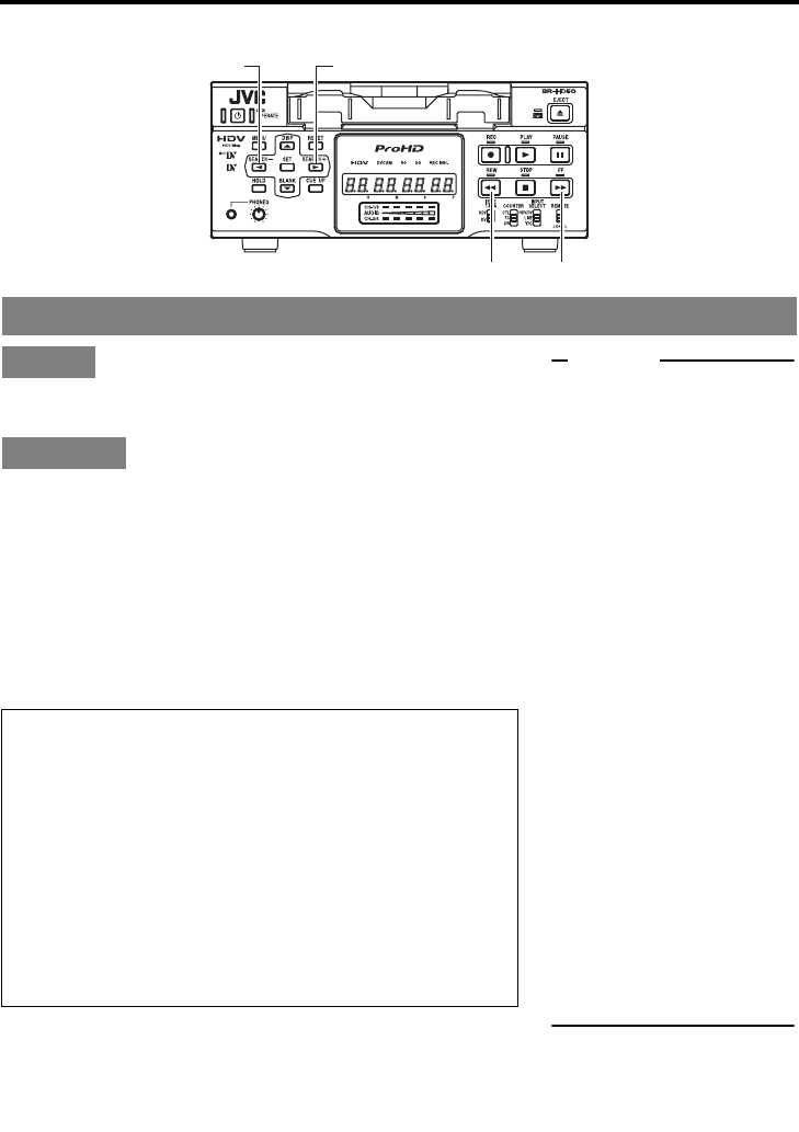
E-53
Set “Q, S” KEY FUNC in the SYSTEM [1/2] Menu
screen to VAR/RECV.
1. Set BR-HD50 to the PLAYBACK or the STILL mode.
2. Press the FF button to start fast-forward playback.
Press the REW button to start reverse playback.
Press the SEARCH+/S button to increase the
search speed. Every time you press this button, the
speed increases more.
Press the SEARCH–/Q button to decrease the
search speed. Every time you press this button, the
speed decreases more.
• Cannot perform slow playback when playing back an HDV
tape.
Slow playback and Search mode
Setting
Operation
Search speed
SEARCH+/S button (Fast) (Slow) SEARCH–/Q button
DV recorded tape playback
×–20··×–9 (U)/ –10(E)··×–5··×–2··×–1··×–0.5··×–0.33··
×–0.2··×–0.1··STILL··×0.1··×0.2··×0.33··×0.5··×1(PLAY)··
×2··×5··×9 (U)/10 (E)··×20
(U): U model
(E): E model
* The maximum speed in the DVCAM mode is 15×.
HDV recorded tape playback
×–16··×–6.5··×–4.5··×–2.5··×–1.5··STILL··×1(PLAY)··
×2.5··×5.5··×8.5··×18
REW button
SEARCH–/Q button SEARCH+/S button
FF button
Memo
zWhether to enable/disable
audio out in the Slow play-
back or SEARCH mode can
be selected with A. OUT AT
SRH: DV in the AUDIO
Menu screen.
zSearch audio is not output
for HDV format.
zPlayback at ± 0.1 × speed is
step-slow playback (continu-
ous frame-advance play-
back/frame-reverse
playback).
zIn step-slow playback, video
is output according to the
STL/F.ADV: DV setting in
the SYSTEM [1/2] Menu
screen. (DV format only)
zWhen step-slow playback is
continued, the speed is
automatically set to ±0.2×.
zDuring slow-playback or
frame-advance, noise is
generated to the output
images from the IEEE1394
terminal. For recording slow-
playback images, use ana-
log output signals of BR-
HD50.
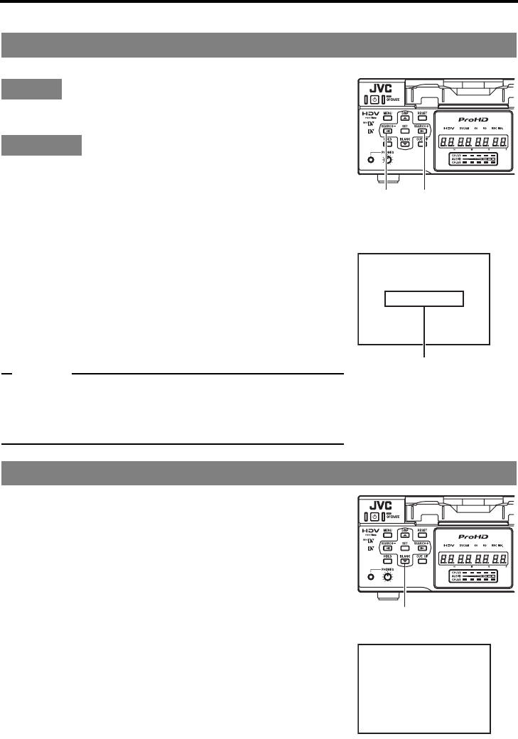
E-54
PLAYBACK
Search function
This function searches to the position where the index signal is recorded.
Set “Q, S” KEY FUNC in the SYSTEM [1/2] Menu screen
to INDEX.
To search an index point in the forward direction
from the current tape position:
• Press the SEARCH+ button.
The index position to be searched can be specified by the
number of times this button is pressed. (Max: 99)
To search an index point in the reverse direction
from the current tape position:
• Press the SEARCH– button.
The index position to be searched can be specified by the
number of times this button is pressed. (Max: 99)
When the SEARCH+ or SEARCH– button is pressed,
the unit fast-forwards or rewinds to the specified
indexed position and start playing.
Memo
zIf the interval between index signals is less than one minute, the
function may not work well.
zThe specifications for index signal recording varies with the
device used.
This function searches unrecorded parts of the tape.
In the STOP mode, press the BLANK button.
• If the current position is at a recorded part of the tape, BR-
HD50 fast-forwards until an unrecorded part is reached
and stops there.
• If the current position is an unrecorded part of the tape,
BR-HD50 will first advance the tape in the forward direc-
tion for confirmation and thereafter rewind and go into the
STILL mode at the last recorded position.
• During a blank search, “BLANK SEARCH” is displayed on
the monitor.
Index search
Setting
Operation
Blank search
INDEX+1
Monitor screen
Index search progressing:
displayed on the screen
(The number denotes the corre-
sponding index position.)
SEARCH
– button
SEARCH
+ button
BLANK SEARCH
Monitor screen
BLANK button
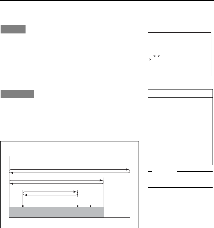
E-55
PLAYBACK
Repeat playback
Three types of repeat playback are available for BR-HD50.
The repeat playback function can be set with REPEAT MODE in the SYSTEM [1/2] Menu screen.
REPEAT MODE in the SYSTEM [1/2] Menu screen
OFF : No repeat playback.
INDEX : Repeat playback between positions where index
signals are recorded.
V. END : Repeat playback from the beginning of the tape to
the position where recording of video signals
ends.
TAPE END : Repeat playback from the beginning to the end of
the tape.
1. Press the REW button to rewind the tape to the beginning.
2. Press the PLAY button to start playback.
When it reaches the position set at REPEAT MODE, the tape
starts rewinding and plays back again.
To abort the repeat playback function, press the
STOP button.
Setting
Operation
Repeat operation
KCABEGAP
EGAPTXEN
XEDNIEDOMTAEPER
VCER/RAV.CNUFYEK”,“
FFO-YBT
S
EDOMESUAPGNOL
CES30EMITESUAPGNOL
FFOVD:CER
NI5MEMITP. GNO C LER
PUKCAB
DN
2
VD:VDA.F/LTS
–––]2/1[METSYS––
–
SYSTEM [1/2] Menu screen
Memo
If the head is dirty, repeat play-
back may not work well.
INDEX repeat playback
zIf no index signal is
detected during playback,
the tape will run until the
end. If no index signal is
detected during rewind, the
tape will rewind until the
beginning.
zIf the interval between
index signals is less than
one minute, the function
may not work well.
TAPE END
V. END
PlaybackINDEX
Rewind
Index signal Index signal
Beginning of tape End of tape
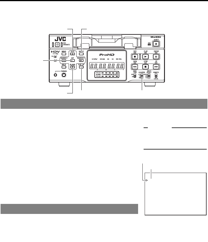
E-56
PLAYBACK
Multi cue-up
Using the time codes recorded on the tape, up to 5 points on the tape can be registered as cue-up
points at the Multi Cue-up screen. The registered tape positions (cue-up points) can be searched.
1. Set the COUNTER switch to TC.
2. Load a tape with time codes recorded.
3. Press the CUE UP button.
The MULTI CUE UP screen appears on the monitor.
4. Perform playback or search. At the position to be regis-
tered, set it to the STILL or STOP mode.
5. Press the R or P button to bring the cursor to the cue-
up point. Press the SET button.
Register the time code data of the current position as a cue-
up point.
• If no tape is loaded, “00” is registered.
• Cue-up points can be registered while the tape is being
played back.
6. To register more cue-up points, repeat steps 4 and 5. Up to
5 cue-up points can be registered.
Press the R or P button to bring the cursor to the cue-up point
to be cleared. Press the RESET button.
After a cue-up point is cleared, “– –” is displayed.
Registering cue-up points
Clearing registered cue-up points
COUNTER swicth
R button RESET button
CUE UP buttonP button
SET button
–––MULT I CUE UP––––––
CUEI 00:01:35:11
CUE2 03:42:59:21
CUE3 ––:––:––:––
CUE4 11:21:48:07
CUE5 ––:––:––:––
EX I T
“SET” :ENTRY CUE DATA
“ RESET ” : CLEAR CUE DATA
“ CUE UP ” : EXECUTE CUE UP
MULTI CUE UP screen
Memo
For details on time code setting
and recording:
(XPage 58)
Cursor
Cue-up point
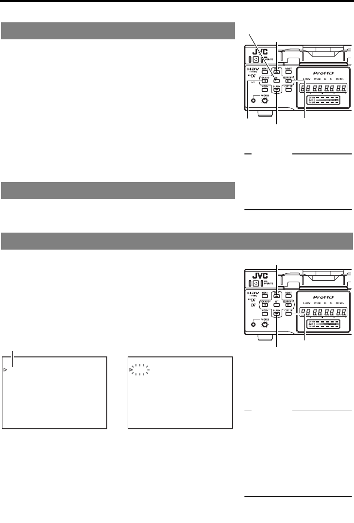
E-57
1Press the R or P button to bring the cursor to the
cue-up point to be changed. Press the S button.
The hour digits of the registered time code display blink.
Press the S button to select the digit to be changed.
2Press the R or P button again to change the time-
code.
Press the R button to increase the time code data.
Press the P button to decrease the time code data.
3Press the SET button to register the changed time
code.
If no time code is to be registered, do not press the SET button.
Instead, press the Q button to make the blinking time code dis-
play disappear.
Press the R or P button to bring the cursor to EXIT. Press the
SET button.
The display of the monitor returns to the normal screen.
1. Set the COUNTER switch to TC.
2. Press the CUE UP button when the normal screen is dis-
played.
The Multi Cue-up screen appears on the monitor.
3. Press the R or P button to bring the cursor to the cue-
up point to be searched.
4. Press the CUE UP button.
The cue-up operation for the selected point is performed.
Changing cue-up points
Exiting the Multi Cue-up screen
Searching cue-up points
Memo
If the COUNTER switch is set
to CTL or UB while the Multi
Cue-up screen is being dis-
played, the display returns to
the normal screen.
SET button
R button
Q button P button
S button
R button
P button CUE UP button
While searching is being per-
formed, the cue-up point to be
searched flashes on the moni-
tor.
Memo
zFor cue-up operation, use
tapes with continuous time
codes recorded.
zIf the COUNTER switch is
set to CTL or UB while the
Multi Cue-up screen is being
displayed, the COUNTER
mode does not change.
–––MULT I CUE UP––––––
CUEI 00:01:35:11
CUE2 03:42:59:21
CUE3 ––:––:––:––
CUE4 11:21:48:07
CUE5 ––:––:––:––
EX I T
“SET” :ENTRY CUE DATA
“RESET” :CLEAR CUE DATA
“ CUE UP ” : EXECUTE CUE UP
–––MULT I CUE UP––––––
CUEI 00:01:35:11
CUE2 03:42:59:21
CUE3 ––:––:––:––
CUE4 11:21:48:07
CUE5 ––:––:––:––
EX I T
“SET” :ENTRY CUE DATA
“RESET” :CLEAR CUE DATA
“ CUE UP ” : EXECUTE CUE UP
Cue-up point
Multi Cue-up screen During cue-up operation
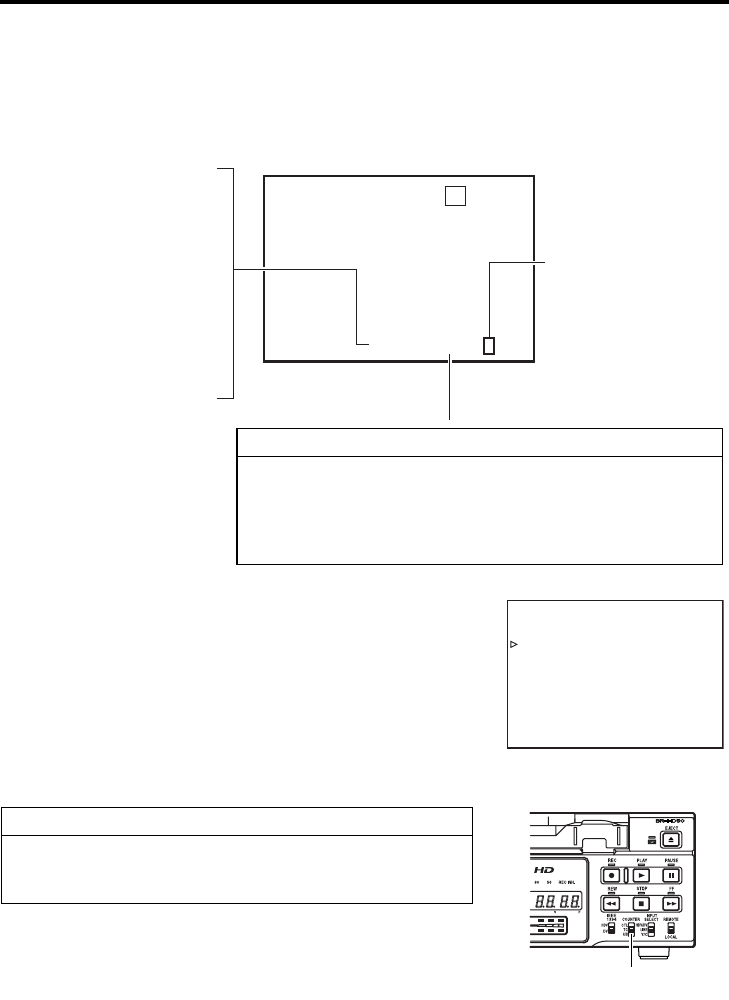
E-58
TIME CODE
Displaying the time code
This unit records or plays back the time code and user’s bit. Whether to record the user’s bit can be
selected with U-BIT in the TC/UB/CLOCK [2/2] Menu screen (only for E model). With the time code
function, accurate positions of the tape contents can be specified to enhance editing precision and
operation efficiency. During recording or playback, the time code and user’s bit are displayed on the
monitor or the Counter display.
To display the time code/ user’s bit, perform the fol-
lowing settings.
• Set DISPLAY in the DISPLAY Menu screen to ON or AUTO.
The status is displayed on the monitor.
• Set TIME CODE in the DISPLAY Menu screen to ON.
The time code, user’s bit or CTL counter is displayed at the
counter display section of the status display.
• Select the counter display mode with the COUNTER switch
on the front panel.
To display the time code, select TC.
To display the user’s bit, select UB.
Checking the data of time code generator
When it is in the STOP mode, press the REC button and the data
of the time code generator will be displayed while the button is
held down.
00:00:00:20RCT00:
0
02:01
1FFO
-
YBDNATS50
1//60
TIBIHNICER
ERULIAFROTOMMURD
1007GNINRA
W
M0PSNI62/1–HCK2VD3
TCG : Time code generator data
TCR : Time code reader data
DTCG : Input time code data from
the IEEE1394 terminal
UBG : User’s bit generator data
UBR : User’s bit reader data
DUBG : User’s bit input data from
the IEEE1394 terminal
Framing mode
(for NTSC only)
: (colon) : Non-drop frame
. (dot) : Drop frame
Status display (Monitor)
Time code/User’s bit display
During recording and stop mode: Data of time code generator
During playback : Data recorded on the tape
During DV input : Data selected with TC DUPLI.
in the TC/UB/CLOCK
Menu screen
–––DISPLAY–––
T
DISPLAY ON
COUNTER POS I . LOWER - R
IME CODE ON
VTR MODE ON
TAP E REMA I N ON
TIME/DATE DATE+TM
A/V INFO. ON
DATE STYLE DD / MM / YY
T IME STYLE 24HOUR
PAGE BACK
DISPLAY Menu screen
The display position can be
selected.
COUNTER switch
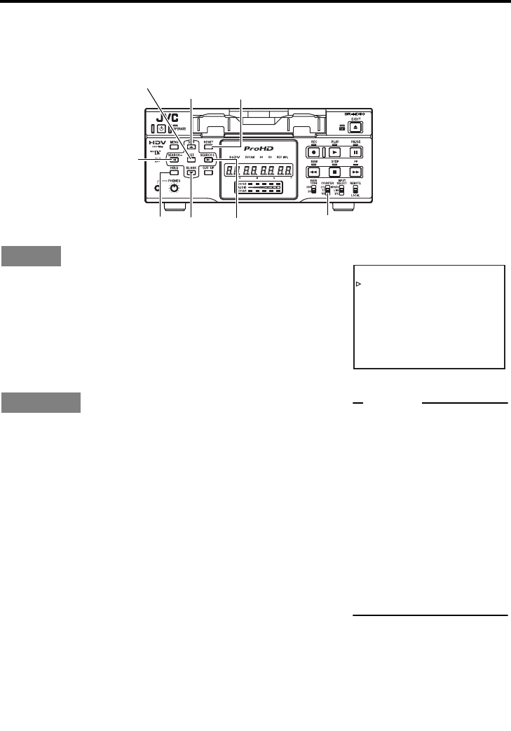
E-59
TIME CODE
Presetting the time code
Variable values can be set for the time code and the user’s bit for efficient material management and
editing.
Set TCG SELECT to “PRESET”.
The time code advance mode is REC-RUN mode.
REC-RUN : The time code runs only during recording.
NDF/DF [60] (U model only)
NON-DROP: Enters non-drop frame mode. Use this setting
when emphasizing the frame count.
DROP : Enters drop-frame mode. Use this setting when
emphasizing the recording time.
This section describes the setting of the time code. The setting of
the user’s bit is the same. Values that can be used to configure the
user’s bit are hexadecimal numeral from 0 - F.
1. Set the COUNTER switch to TC.
(For user’s bit, set the switch to UB.)
2. In the STOP mode, press the HOLD button.
The hour digit of the counter starts blinking.
3. Press the R or P button to change the value.
4. Press the S or Q button to move blinking to the next
digit.
5. Press the R or P button to change the value of the blink-
ing digit.
6. Repeat steps 4 and 5 to perform the necessary settings.
7. Press the SET button to confirm the setting value and
blinking of the counter stops.
The setting is preset to the time code generator.
Setting ...TC/UB/CLOCK [1/2] Menu screen
Operation
...Perform setting while checking the Counter display.
SET button
DISP/R button RESET button
Q button
HOLD button P button S button COUNTER switch
KCABEGAP
EGAPTXEN
FFOTESFFOCT
NO
FFO.ILPUDCT
]05[TIBFD
PORD]06[FD/FDN
TESERPTCELESGCT
–––2/1[]KCOLC/BU/CT––
–
TC/UB/CLOCK[1/2] Menu screen
Memo
zTo stop the setting, press
the HOLD button to return to
the normal screen.
z
To preset all digits to 0, press
the RESET button when any
of the digits is blinking.
z
When the hour digit is blink-
ing, the frame digit starts
blinking when the
Q
button
is pressed.
z
If a user’s bit is input with its
all digits set as “F”, BR-HD50
converts FFFFFFFF to
FFFFFFF
E
before recording.
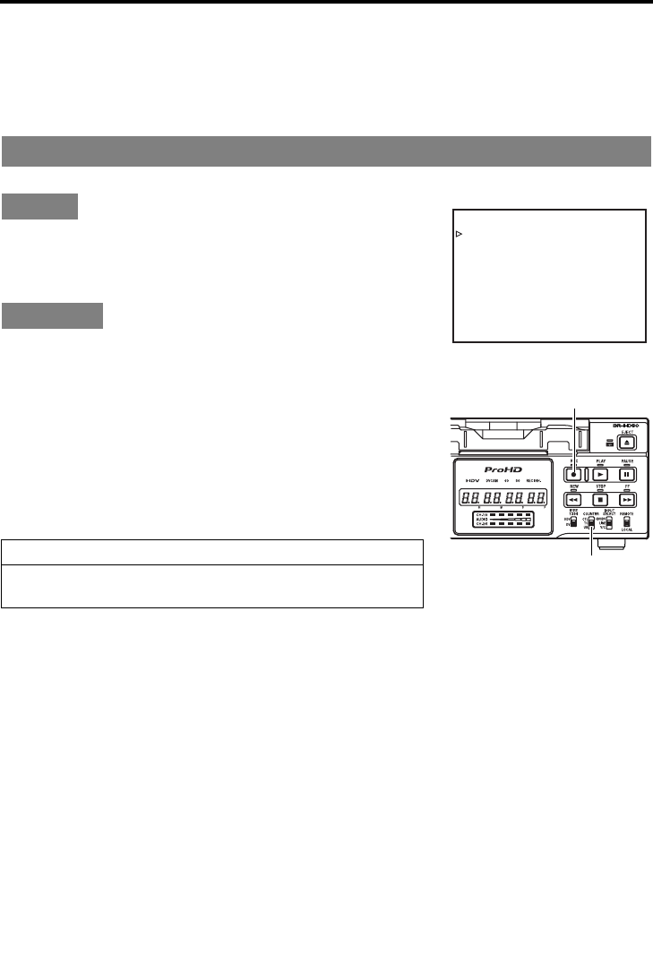
E-60
TIME CODE
Recording the time code
Time codes can be recorded with the following ways. Whether to record user’s bit can be selected with
U-BIT in the TC/UB/CLOCK [2/2] Menu screen. (Only for E model)
zRecord it from preset data.
zRecord it following the one last recorded on the tape.
zRecord the time code, which is input to the IEEE1394 terminal.
Record preset time code data to the internal time code generator in the TIME CODE Preset screen.
Set the TC/UB/CLOCK [1/2] Menu as follows.
TCG SELECT :PRESET
The time code advance mode is REC-RUN mode.
NDF/DF [60] : NON DROP or DROP (U model only)
1. Check the preset time code.
1Set the COUNTER switch to TC or UB.
2In the STOP mode, hold down the REC button.
The preset time code or the user’s bit is displayed on the
monitor. The counter mode is displayed as TCG or UBG.
3When the REC button is released, it returns to the origi-
nal display.
2. Record.
Press the PLAY button while holding down the REC button.
The time code and user’s bit are recorded.
To stop recording, press the STOP button.
Recording from preset data
Setting
Operation
Preset time code
Stopping the power supply to the DV IN terminal of BR-HD50 can-
cels the preset value of the time code generator.
KCABEGAP
EGAPTXEN
FFOTESFFOCT
NO
FFO.ILPUDCT
]05[TIBFD
PORD]06[FD/FDN
TESERPTCELESGCT
–––2/1[]KCOLC/BU/CT––
–
TC/UB/CLOCK [1/2] Menu screen
REC button
COUNTER switch
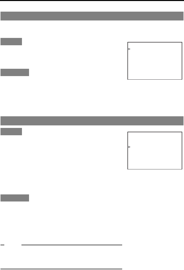
E-61
BR-HD50 is equipped with a time code reader. When it enters the RECORD mode from the RECORD-
ING PAUSE mode, it reads the time code data already recorded on the tape and continues recording
time code from that value. (Regeneration)
Set the TC/UB/CLOCK [1/2] Menu as follows.
TCG SELECT :REGEN
NDF/DF [60] : No setting required. The framing mode will
match the tape. (U model only)
1. Insert a tape with time codes recorded.
2. Set BR-HD50 to the RECORDING PAUSE mode at the posi-
tion where time codes are to be recorded again.
3. Press the PLAY button to go to the RECORDING mode.
Time codes will be recorded on the tape, starting from where
it stopped at last recording.
The counter mode display shows either TCR or UBR.
Set the INPUT SELECT switch and the IEEE1394
switch on the front panel to HDV/DV.
DV - : When dubbing a DV format recorded tape
HDV -: When dubbing an HDV format recorded tape
Connect the Playback unit and BR-HD50 with an
IEEE1394 cable.
Set TC DUPLI. in the TC/UB/CLOCK [1/2] Menu
screen to AUTO.
* To record the time code from a BR-DV600 or GY-DV500 in non-
drop frame mode, set TC DUPLI. to NON DROP. (U model only)
1. Insert video cassettes.
BR-HD50 : Insert video cassette to be dubbed to
Playback unit: Insert the recorded cassette
2. Start playback in DV/HDV mode on the playback unit.
For details see playback unit instructions.
3. Start recording on the BR-HD50.
Press the PLAY button while holding down the REC button.
Note
In DV mode. . . . The date and time data inputted to IEEE1394 ter-
minal is also recorded.
In HDV mode . . The user bits and the date and time data recorded
will be determined by the settings on this deck.
Recording time code following the one last recorded on the tape
Setting
Operation
Dubbing video and time code inputted to the IEEE1394 terminal
Setting
Operation
KCABEGAP
EGAPTXEN
FFOTESFFOCT
NO
FFO.ILPUDCT
]05[TIBFD
PORD]06[FD/FDN
NEGERTCELESGCT
–––2/1[]KCOLC/BU/CT––
–
TC/UB/CLOCK [1/2] Menu screen
KCABEGAP
EGAPTXEN
FFOTESFFOCT
O
NO
TUA.ILPUDCT
]05[TIBFD
PORD]06[FD/FDN
TESERPTCELESGCT
–––2/1[]KCOLC/BU/CT––
–
TC/UB/CLOCK [1/2] Menu screen
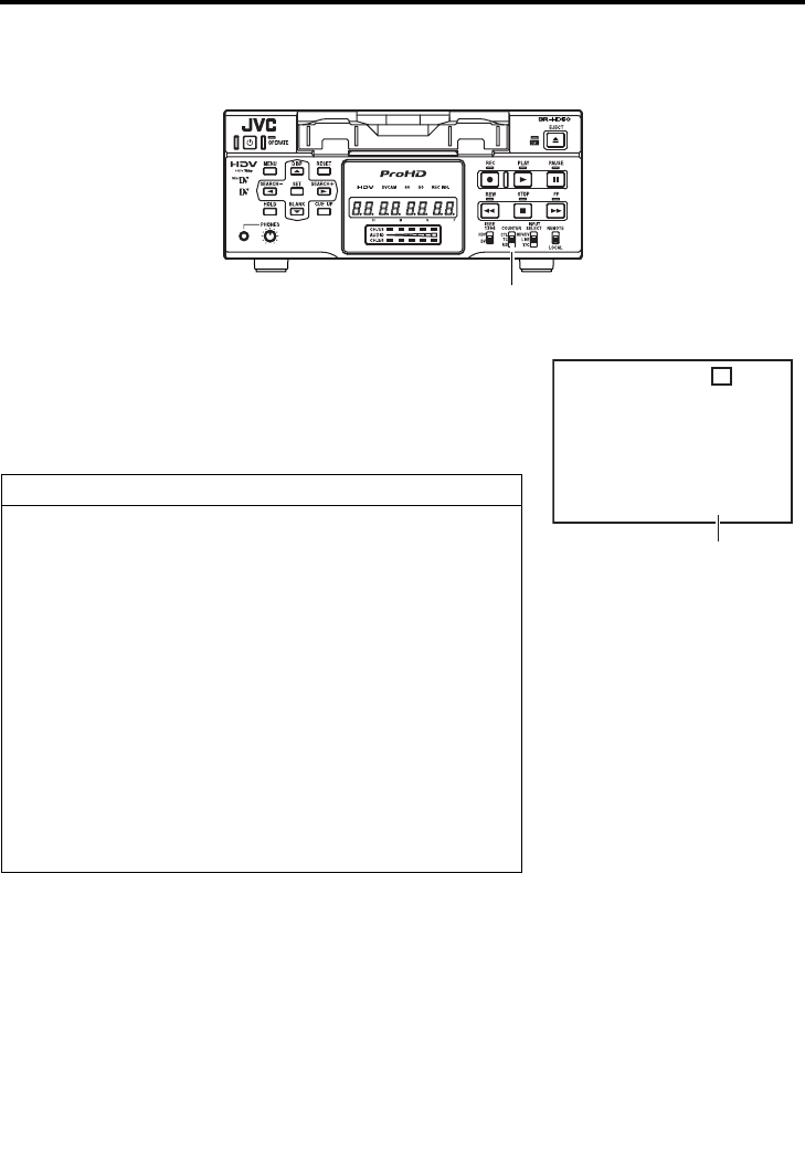
E-62
TIME CODE
Playing back the time code
BR-HD50 is also equipped with a time code reader. During playback, the time code or user’s bit data
recorded on the tape is displayed on the monitor or the counter display.
1. Select the time code data to display.
Set the COUNTER switch to “TC” or “UB”.
2. Press the PLAY button to go to the PLAYBACK mode.
It displays the time code and the user’s bit on the monitor or
the counter display. The counter display mode becomes TCR
or UBR.
Caution on time code playback
zDuring playback, if a portion of tape without recorded time
code runs through, the time code stops running. Playback con-
tinues.
zIf tapes without recorded user’s bit, e.g. those recorded with a
home-use DV VCR, are played back on BR-HD50, “– –” is dis-
played.
zWhen playing back an HDV recorded tape, the frame counter
of the time code is displayed according to the recorded signal
format.
720/30p…30 frame progressive
720/24p…24 frame progressive
480/60p…60 frame progressive
720/25p…25 frame progressive
576/50p…50 frame progressive
720/60p…60 frame progressive
720/50p…50 frame progressive
COUNTER switch
3DV 2 K CH– 1 / 2 S M I NP60
W
ARNING 7001
DRUM MOTOR FA I LURE
REC INHIBIT
06 / 10 / 05 PLAY
11:20:00 TCR 02:00:00:00
Monitor (Status display)
Time code or user’s bit
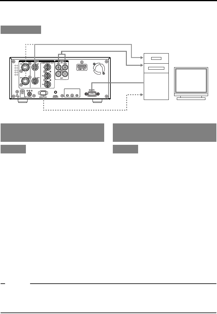
E-63
EDIT
Using a non-linear editing system
Tape contents of BR-HD50 are captured by a non-linear editing system and the non-linear edited con-
tents are recorded on BR-HD50.
Set the REMOTE/LOCAL switch on the
front panel to REMOTE.
REMOTE [1/2] Menu screen
• Set REMOTE SEL 9-PIN to “ON”.
REMOTE [2/2] Menu screen
zREMOTE FF/REW MODE:
Use this item to select the operation to be per-
formed if the FF or REW command is received
during playback. (FF/REW or Search)
If the search operation is not performed prop-
erly, set it to “SEARCH”.
zCONTROLLER TYPE (in the REMOTE [2/2]
Menu screen):
Set this item to “TYPE1”.
Set the INPUT SELECT switch located
on the front panel to HDV/DV.
Set the IEEE1394 switch located on
the front panel to match the video for-
mat.
• Set to DV position for DV mode, and to
HDV position for HDV mode.
Set the REMOTE/LOCAL switch on the
front panel to the position matching
the REMOTE menu below.
REMOTE [1/2] Menu screen
•
Set REM SEL HDV/DV to ON or LOC+REM.
Set this item to ON if it is to become
enabled only when the REMOTE/LOCAL
switch on the front panel is set to REMOTE.
Set this item to LOC+REM if it is to become
enabled regardless of the position of the
REMOTE/LOCAL switch.
Memo
zIf the time code of BR-HD50 is not displayed correctly when the non-linear side moves one frame
forward or backward, set the STL/F.ADV: DV in the SYSTEM [1/2] Menu screen to “FRAME.” (In DV
mode only)
zWhen controlling with RS-422A using the HDV format, only the capture operation is supported.
Connection
Analog video
IEEE1394 terminal
VIDEO OUT
AUDIO OUT
RS-422A
REMOTE
Analog audio
Non-linear system
IEEE1394 (image, audio, control)
Control with RS-422A
(Analog signals)
Setting
Control with the IEEE1394 ter-
minal (Digital signals)
Setting
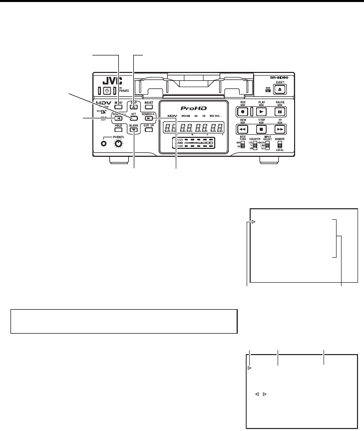
E-64
MENU SCREENS
Setting the menus
The functions of BR-HD50 are configured in the Menu screens. The configured settings are saved in
the memory of BR-HD50 and retained even after power off.
Perform the menu settings while viewing the display on the moni-
tor.
The counter display shows menu code numbers.
Set BR-HD50 to the STOP or STILL mode.
1. Displaying the TOP MENU screen.
Press the MENU button.
2. Displaying the Menu screen items for setting.
1Press the R or P button to bring the cursor to the Menu
screen item for setting.
2Press SET or the S button.
3. Setting the Menu item for setting.
1Press the R or P button to bring the cursor to the Menu
screen item for setting.
2Press SET or the S button.
The selected setting value blinks and becomes available
for changing.
3Press the R or P button to change the value.
4Press the SET button to confirm the change.
Blinking stops and the new value is confirmed.
5Repeat steps 1 - 4 and continue setting as necessary.
Select EXIT of the TOP Menu screen to return to the normal
screen.
MENU button R button
SET button
P button S button
Q button
KCABEGAP
EGAPTXEN
FFOEDOMTAEPER
VCER/RAV.CNUFYEK”,“
FFO-YBT
S
EDOMESUAPGNOL
CES30EMITESUAPGNOL
FFOVD:CER
NI5MEMITP GNOL CER .
PUKCAB
DN
2
VD:VDA.F/LTS
–––]2/1[METSYS––
–
TIXE
..TESYALPSID
..KCOLC/BU/CT
..OEDIV
..OIDUA
..ETOMER
..METSYS
–––UNEM––
–
TOP Menu screen
Cursor
Cursor
Menu Items
Setting valueItem
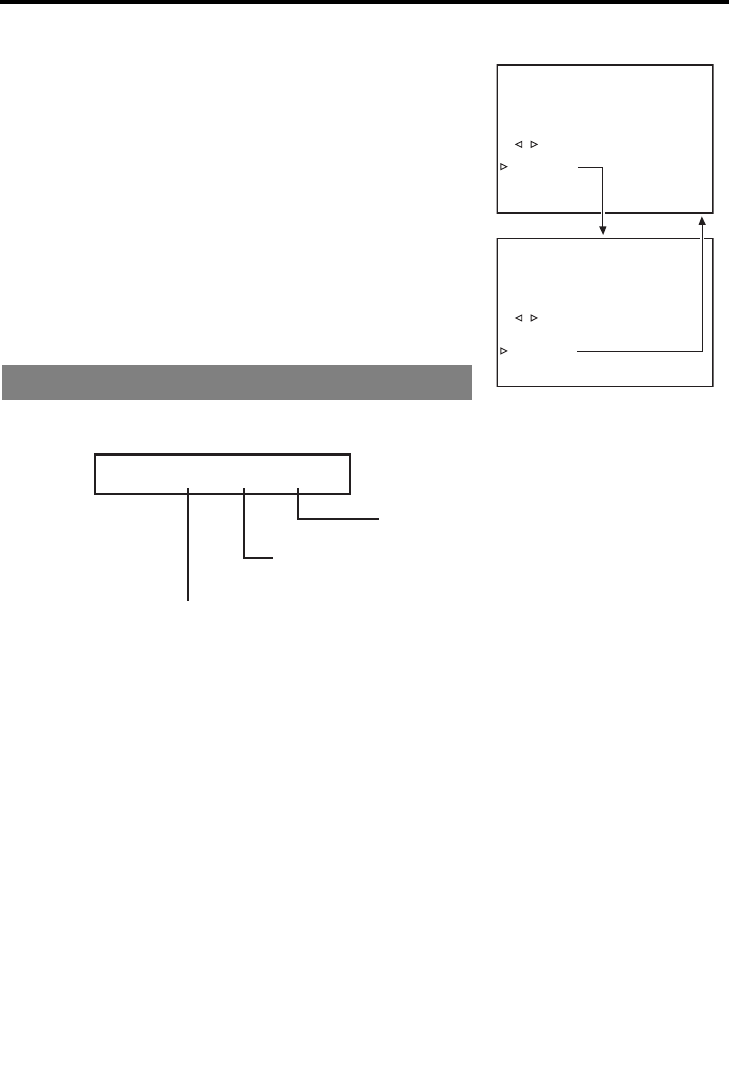
E-65
To display the Menu screen at the next level, bring
the cursor to NEXT PAGE and press the SET or S
button.
To return to the previous Menu screen, do one of the
following actions.
• Press the S button.
Or
• Select PAGE BACK and press the SET or S button.
4. To return to the normal screen, do one of the following
actions.
• Press the MENU button.
Or
• Select EXIT in the TOP Menu screen and press the SET or
S button.
The counter display shows menu code numbers when setting
menus.
• Menu display : Flashes when the TOP MENU screen is dis-
played.
• Items : Flashes when each menu screen is displayed.
(No settings are selected yet.)
• Setting : Flashes when a menu item is selected and the
setting on the monitor display is flashing.
Menu screen on counter display
KCABEGAP
EGAPTXEN
FFOEDOMTAEPER
VCER/RAV.CNUFYEK”,“
FFO-YBT
S
EDOMESUAPGNOL
CES30EMITESUAPGNOL
FFOVD:CER
NI5MEMITP. GNO L CER
PUKCAB
DN
2
V:VDA.F/LTS D
–––]2/1[METSYS––
–
KCABEGAP
EGAPTXEN
FFOEDOMTAEPER
CVER/RAV.CNUFYEK”,“
FFO-YBT
S
EDOMESUAPGNOL
CES30EMITESUAPGNOL
FFOVD:CER
NI5MEMITP. GNO CLER
PUKCAB
DN
2
VD:VDA.F/LTS
–––]2/1[METSYS––
–
SYSTEM [1/2] Menu screen
SYSTEM [2/2] Menu screen
01 05 00
(Example) 01: SYSTEM Menu screen
Menu screen
Setting value
Items
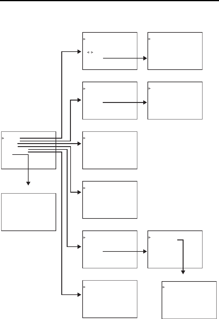
E-66
MENU SCREENS
Structure of the Menu screens
The Menu screens are displayed on the monitor. They are structured with multiple layers.
– – –MENU – – –
SYSTEM. .
REMOTE . .
AUD I O . .
VIDEO. .
TC/UB/CLOCK. .
D I SPLAYSET . .
EX I T
–––SYSTEM[ 1 / 2 ] ––––––
STL / F . ADV : DV 2ND
BACKUP REC : DV OFF
LONG PAUSE T IME 3 0SEC
REC LONG P .TIME 5MIN
LONG PAUSE MODE ST BY - OF F
“ , ” KEY FUNC . VAR / REC
VREPEAT MODE OFF
NEXT PAGE
PAGE BACK
–––AUDIO–––
AUD I O MODE : DV 4 8 K
A.OUTPUT :DV CH1/2
A.OUTATSRH:DV ON
AUD IO OUT LEV - 2 0dB
V.FADE :DV O
BTHO
N
A
PAGE BACK
. REC VR D . : DVM
.
–––
REMOTE [ 1 / 2 ]
–––
REMOTE SE L 9 P ON
REMOTE SE L SER ON
REM SEL HDV / DV ON
LOCA L FUNCT I ON ST P +E J T
PREROL L 7 SEC
NEXT PAGE
PAGE BACK
–––VIDEO–––
SET UP [ 6 0 ] : DV ON
O
MON I TOR SE LECT HDM I [ A ]
UT FORMAT [ 60 ] NAT I VE
O
H
D
T
PAGE BACK
EST S I GNAL OFF
VI OC LOR STAND RDA
DM I MODE AU TO
UT FORMAT [ 50 ] N
S
FUL L
UP CONV .
QUE EZ E
AT I VE
DOWN C .
MODE
MODEONV
– – – TC / UB / CLOCK [ ]1/2 ––––
TCG SELECT REGEN
NDF / DF [ 6 0 ] DROP
DF B I T [ 5 0 ] ON
TC DUPL I . OFF
TC OFFSET OFF
NEXT PAGE
PAGE BACK
–––DI SPLAY–––
DISPLAY ON
COUNT ER POS I . LOWER - R
TIME CODE ON
VTR MODE ON
TAPE REMA I N ON
TIME/DATE D
D
2H
4OUR
T
PAGE BACK
IME STY EL
D/MM/YY
TAE+MT
A/V INFO. ON
DATE STY E
L
–––REMOTE[ 2 / 2 ] –––
REM FF / REW MODE FF / REW
REM STOP SE L . EE
PB START DELAY 0F
SYNCHRON I ZA T I ON ON
CON TRO L L E R SE L T YPE 1
FOOT SW OFF
PAGE BACK
–––SYSTEM[ 2 / 2 ] ––––––
DC I N MODE OPE OF F
INDEX WRITE ON
OPERA T I ON LOCK OF F
60 / 50 SEL 50
FACTORY SETT I NG CANCEL
DRUM HOUR METER 0 0 0 0 0 0
PAGE BACK
–––TC/UB/CLOCK[ ]2/2 –
––
U-BIT[ 50]
CLOCK ADJUST . .
PAGE BACK
–––CLOCK ADJUST–––
DATE(DD/MM/YY) 06/10/05
TIME 00:00
PAGE BACK
MO N OUT ASPEC FUL LT
.
Top menu
Normal screen
SYSTEM [1/2] menu
REMOTE [1/2] menu
AUDIO menu
VIDEO menu
TC/UB/clock [1/2] menu
DISPLAY menu
SYSTEM [2/2] menu
REMOTE [2/2] menu
TC/UB/clock [2/2] menu
CLOCK ADJUST menu
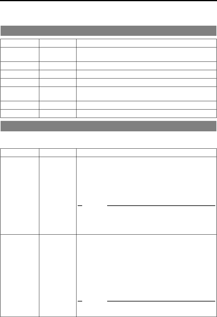
E-67
MENU SCREENS
Description of the Menu screens
In the following description of the Menus, E indicates factory settings.
Numbers in parentheses by items and settings are the code number shown on the counter display.
The SYSTEM Menu consists of the following two screens (1/2 and 2/2).
SYSTEM [1/2] Menu screens
TOP Menu screen
Item Setting Description
SYSTEM.. –Displays the menus related to the operating system of BR-HD50.
It also displays factory setting and the drum hour meter.
REMOTE.. – Displays the menus related to the remote controller.
AUDIO.. – Displays the menus related to the audio.
VIDEO.. – Displays the menus related to the video.
TC/UB/CLOCK.. –Displays the menu for setting time codes.
Also displays the date/time setting screen.
DISPLAYSET.. – Displays menus related to on-screen display.
EXIT – Return to the normal screen.
SYSTEM Menu screens
Item Setting Description
STL/F.ADV: DV
(0100)
FIELD (00)
1ST (01)
E2ND (02)
FRAME (03)
Use this setting to select the still image for the STILL mode or
frame-advance playback. (During DV format video playback)
FIELD
: Displays the field image. During frame-advance play-
back, it displays the 1st and 2nd field images alternately.
1ST : Displays the 1st field image.
2ND : Displays the 2nd field image.
FRAME: Displays the frame image.
Memo
zPlayback of HDV format tapes is always in frame image output,
regardless of menu settings.
zThe first field image is displayed as the DV output image from
the IEEE1394 terminal, regardless of the settings.
BACKUP REC
: DV
(0101)
EOFF (00)
25MIN (01)
55MIN (02)
75MIN (03)
115MIN (04)
175MIN (05)
265MIN (06)
For setting backup recording time with DV input signals according
to the tape length of the source unit:
OFF : No backup recording
25MIN : For a 30-minute source unit recording tape
55MIN : For a 60-minute source unit recording tape
75MIN : For a 80-minute source unit recording tape
115MIN : For a 120-minute source unit recording tape
175MIN : For a 180-minute source unit recording tape
265MIN : For a 270-minute source unit recording tape
(XPage 47 “Backup recording function”)
Memo
Set this item to “OFF” if DV REC TRIGGER of GY-DV5000/
DV5100 is set to ON.

E-68
MENU SCREENS
Description of the Menu screens (continued)
SYSTEM Menu screens (continued)
Item Setting Description
LONG PAUSE
TIME
(0102)
E30SEC (00)
1MIN (01)
2MIN (02)
3MIN (03)
5MIN (04)
Select the time when BR-HD50 enters the TAPE PROTECTION
mode if the unit has stayed at still or stop for a prolonged period of
time. The TAPE PROTECTION mode in at STILL can be selected
from LONG PAUSE MODE:
30SEC : 30 seconds
1MIN : 1 minute 3MIN : 3 minutes
2MIN : 2 minutes 5MIN : 5 minutes
Memo
To prevent the video head from clogged or the tape from being
damaged, set as short a time as possible.
REC LONG
P. T I M E
(0103)
30SEC (00)
1MIN (01)
2MIN (02)
3MIN (03)
E5MIN (04)
Select the time when BR-HD50 enters the TAPE PROTECTION
mode if the unit has stayed at recording pause for a prolonged
period of time.
30SEC : 30 seconds
1MIN : 1 minute 3MIN : 3 minutes
2MIN : 2 minutes 5MIN : 5 minutes
Memo
To prevent the video head from clogged or the tape from being
damaged, set as short a time as possible.
LONG PAUSE
MODE
(0104)
F.ADV (00)
E
STBY-OFF (01)
For selecting the action when BR-HD50 stays at still for a long time.
In the case of RECORDING PAUSE or STOP, it enters the
STANDBY-OFF status:
F.ADV : Frame-advances BR-HD50 five times in the forward
direction. On the 6th attempt, this mode stops it.
STBY-OFF : Stops BR-HD50.
“Q,S” KEY
FUNC.
(0105)
INDEX (00)
EVAR/RECV
(01)
For selecting the function for the SEARCH+/S button and
SEARCH–/Q button.
INDEX : Performs index search. (XPage 54)
VAR/RECV :
Changes the search speed during a search. (
XPage 53
)
Enables adjusting analog audio input level. (
XPage 44
)
REPEAT MODE
(0106)
EOFF (00)
INDEX (01)
V. END (02)
TAPE END (03)
For enabling/disabling repeat playback and selecting the type of
repeat playback.
OFF : No repeat playback
INDEX : Repeat playback between the positions where
index signals are recorded.
V. END : Repeat playback from the beginning of the tape to
the position where video signal recording ends.
TAPE END : Repeat playback from the beginning to the end of
the tape.
NEXT PAGE For displaying the SYSTEM [2/2] Menu screen.
PAGE BACK For returning to the TOP Menu screen.

E-69
SYSTEM [2/2] Menu
Item Setting Description
DC IN MODE
(0107)
E
OPE OFF (00)
OPE ON (01)
For selecting the action to perform when the power is supplied to
the DC IN terminal:
OPE OFF : Sets BR-HD50 to the OPERATE OFF mode.
OPE ON : Sets BR-HD50 to the OPERATE ON mode.
INDEX WRITE
(0108)
OFF (00)
EON (01)
For enabling/disabling index signal recording.
OFF : No index signal
ON : Select here to record index signals.
It records an index signal automatically at the position
where recording starts.
OPERATION
LOCK
(0109)
EOFF (00)
ON (01)
For enabling/disabling OPERATION LOCK.
OFF : Turns off OPERATION LOCK and the operation buttons of
BR-HD50 can be used.
ON : Turns on OPERATION LOCK. The operation buttons and
slide switches of BR-HD50 are disabled except the OPER-
ATE ON button and MENU operation. (XPage 36)
60/50 SEL
(010A)
60 (00)
50 (01)
Sets HD video signal format to 60Hz or 50Hz.
This menu item applies only to HDV format.
This must be set in the following situations.
• Set this menu item to match the input video signal format when
inputting HDV signals to the IEEE1394 terminal.
• Set this menu item to match the video format recorded on the
tape when playing a tape recorded with HDV signals.
60 : The HD signal format becomes 60Hz.
50 : The HD signal format becomes 50Hz.
[Settings upon shipping: U model: 60, E model: 50]
Memo
zThe unit restarts when this menu setting is changed.
z
The front panel 60 or 50 indicator is lit, according to this menu setting.
z
Recording and playback are unavailable when this menu setting dif-
fers from the HDV input signal or HDV recorded tape signal format.
z
During DV/analog signal input or when playing a tape recorded with DV/
analog signals, the field frequency format is fixed for the region, regard-
less of this menu setting. [U model: 60Hz (NTSC), E model: 50Hz (PAL)]
FACTORY SET-
TING
(010b)
ECANCEL (00)
EXECUTE (01)
For enabling/disabling the factory setting for the Menu screens.
CANCEL : Disable the factory setting
EXECUTE: Enable the factory setting
Memo
The unit restarts when this menu setting is executed.
PB TAPE
FORMAT
(010c)
EAUTO (00)
DV (01)
HDV (02)
DVCAM (03)
Selects whether to automatically detect playback tape video for-
mat, or to playback only a specific format.
AUTO : Automatically detects and plays back all video formats.
DV : Plays back only video in DV format.
HDV : Plays back only video in HDV format.
DVCAM : Plays back only video in DVCAM format.
Memo
zWhen set to a specific format and a tape with a different format
is played back, there will be noise in the video.
zIf you play back a tape containing both DV and HDV formats,
the video signal is disturbed when the signal is switched.
DRUM HOUR
METER
For displaying the time of drum usage.
* The cursor cannot be brought to this item.
PAGE BACK For returning to the SYSTEM [1/2] Menu screen.

E-70
MENU SCREENS
Description of the Menu screens (continued)
The REMOTE Menu consists of the following two screens (1/2 and 2/2).
REMOTE [1/2] Menu screen
REMOTE Menu screens
Item Setting Description
REMOTE SEL
9P
(0200)
OFF (00)
EON (01)
For enabling/disabling the REMOTE terminal when the REMOTE/
LOCAL switch on the front panel is set to REMOTE.
OFF : Control through RS-422A disabled.
ON : Control through RS-422A enabled.
REMOTE SEL
SER
(0201)
OFF (00)
EON (01)
LOC+REM (02)
For enabling/disabling control via the SERIAL REMOTE terminal.
OFF : Control disabled regardless of the settings of the
REMOTE/LOCAL switch.
ON : Control enabled only when the REMOTE/LOCAL
switch is set to REMOTE.
LOC+REM : Control enabled regardless of the settings of the
REMOTE/LOCAL switch.
REM SEL
HDV/DV
(0202)
OFF (00)
EON (01)
LOC+REM (02)
For enabling/disabling control via the IEEE1394 terminal.
OFF : Control disabled regardless of the settings of the
REMOTE/LOCAL switch.
ON : Control enabled only when the REMOTE/LOCAL
switch is set to REMOTE.
LOC+REM : Control enabled regardless of the settings of the
REMOTE/LOCAL switch.
LOCAL
FUNCTION
(0203)
NO KEY (00)
EJECT (01)
E
STP+EJT (02)
ALL KEYS (03)
For selecting the buttons of BR-HD50 to be enabled in remote-
controlling it with the REMOTE terminals or the SERIAL REMOTE
terminal:
NO KEY : No button enabled.
EJECT : Only the EJECT button enabled.
STP + EJT : Only the STOP button and the EJECT button are
enabled.
ALL KEYS : All operation buttons are enabled.
Memo
If OPERATION LOCK in the SYSTEM [2/2] Menu screen is set to
ON, the buttons on BR-HD50 will be disabled regardless of the
setting here.
PREROLL
(0204)
3SEC (00)
5SEC (01)
E7SEC (02)
10SEC (03)
For setting the preroll time of BR-HD50 in remote-controlling it
with the REMOTE terminal. Setting done with the editing remote
controller prevails over other settings:
3SEC : 3 seconds 7SEC : 7 seconds
5SEC : 5 seconds 10SEC: 10 seconds
Memo
To enhance editing precision, please set it to at least 7 seconds.
NEXT PAGE For displaying the REMOTE [2/2] Menu screen.
PAGE BACK For returning to the TOP Menu screen.

E-71
REMOTE [2/2] Menu screen
Item Setting Description
REM FF/REW
MODE
(0205)
EFF/REW (00)
SEARCH (01)
For setting the action to be performed when the REMOTE termi-
nal or IEEE1394 terminal received an FF/REW command:
FF/REW : Sets BR-HD50 to perform FF/REW when an FF/REW
command is received. Normal setting.
SEARCH : Sets BR-HD50 to perform searching when an FF/
REW command is received. Use this setting if the
search (cue up) function does not work properly.
REM STOP SEL
(0206)
EEE (00)
PB (01)
For setting the action to be performed when the REMOTE termi-
nal received a STANDBY-ON command:
EE
: Sets BR-HD50 to the EE mode. (It goes into the STOP mode.)
PB
: Sets BR-HD50 to the PLAY mode. (It goes into the STILL mode.)
PB START
DELAY
(0207)
E0F (00)
|
9F (09)
10F (0A)
|
15F (0F)
For adjusting the edit timing. With the remote controller in use, if
the start points of edit are not concurrent, adjust the playback
startup timing:
0F : No correction.
1F to 15F : Delays the timing by the number of frames set by the
user. When BR-HD50 is connected to an editing
remote controller with no bump function, use this set-
ting to adjust the editing precision.
SYNCHRONI-
ZATION
(0208)
OFF (00)
EON (01)
For enabling/disabling the bump function when BR-HD50 is con-
nected to an editing remote controller:
OFF: No synchronization.
ON : Performs synchronization. The editing precision is
enhanced. Please set the pre-roll time to at least 7 seconds.
CONTROLLER
SEL
(0209)
ETYPE1 (00)
TYPE2 (01)
TYPE3 (02)
TYPE4 (03)
TYPE5 (04)
TYPE6 (05)
TYPE7 (06)
For setting the type of controller to be connected when remote
control is enabled with the RS-422A interface:
TYPE1 : RM-G820
TYPE2 : RM-G860 (set the preroll time to at least 10 seconds)
TYPE3 : AG-A850
TYPE4 : RM-450, PVE-500
TYPE5 : FXE-100, FXE-120
TYPE6 : (Not in use)
TYPE7 : Avid Xpress DV, Canopus
DV Rex-RT Professional
FOOT SW
(020A)
EOFF (00)
L EDGE (01)
H EDGE (02)
L LEVEL (03)
For setting when an external switch (e.g., a footswitch) is con-
nected to the SERIAL REMOTE terminal. Before operating an
external switch (footswitch) with L EDGE or H EDGE, turn BR-
HD50 to the RECORDING PAUSE or RECORDING mode:
OFF : For when the external switch is not used.
L EDGE : Recording and recording pause is switched at the
LOW edge of the external switch signal.
H EDGE : Recording and recording pause is switched at the
HIGH edge of the external switch signal.
L LEVEL : Record at the LOW edge and pause recording at the
HIGH edge of the external switch signal.
PAGE BACK Return to the REMOTE [1/2] Menu screen.

E-72
MENU SCREENS
Description of the Menu screens (continued)
AUDIO Menu Screen
Item Setting Description
AUDIO MODE
: DV
(0300)
32K (00)
E48 K (01)
For selecting the audio sampling frequency for analog audio
recording.
32 K : Records at 32 kHz. Up to four channels of recording tracks
are available, but this unit only records onto two of these
channels.
48 K :
Records at 48 kHz. It records in the 2-channel stereo mode.
Memo
Setting this item is not required for DV signal or HDV signal input.
The audio mode will match the input signal.
A.OUTPUT: DV
(0301)
ECH1/2 (00)
MIX (01)
CH3/4 (02)
Select the audio channel for output signals from the AUDIO OUT
terminal or PHONES terminal. Select the following audio choices.
(In DV format mode only)
• Playback audio of tapes recorded in 32 kHz audio mode
• EE audio of DV signal input in 32 kHz audio mode
CH1/2: Outputs audio of channels CH1 and CH2.
MIX : Outputs mixed sound of CH1 and CH3 to the CH1/3 ter-
minal, and the mixed sound of CH2 and CH4 to the CH2/
4 terminal.
CH3/4: Outputs audio of channels CH3 and CH4.
A.OUT AT
SRH: DV
(0302)
OFF (00)
EON (01)
For enabling/disabling audio output from this AUDIO OUT termi-
nal during slow playback or searches. (In DV format mode only)
OFF: Output off.
ON : Output on.
Memo
When playing back an HDV format tape, search audio is not out-
put.
AUDIO OUT
LEV
(0303)
E–20 dB (00)
–12 dB (01)
For selecting the level for playback audio output.
–20 dB : Usually, this setting is used.
–12 dB : Select here to reduce the analog sound output level. It
will be reduced by 8 dB.
V.FADE: DV
(0304)
OFF (00)
EON (01)
For enabling/disabling the V.FADE function, which reduces sound
noise in playback that is produced at jointed parts of recording.
OFF : V.FADE function disabled.
ON : V.FADE function enabled.
Memo
When playing back an HDV format tape, the V. FADE function is
unavailable.
A REC VR.MD.:
DV
(0305)
EBOTH (00)
INDEPEND (01)
Select audio recording level adjustment method.
Select whether to adjust both channels simultaneously, or to
adjust each channel separately.
BOTH : Simultaneously adjusts both channels.
INDEPEND : Adjusts both channels separately.
PAGE BACK For returning to the TOP Menu screen.

E-73
VIDEO Menu Screen
Item Setting Description
SET UP [60]: DV
(0400)
OFF (00)
EON (01)
For enabling/disabling the application of setups to analog video
signals (composite, Y/C and SD component).
(During recording and playback) (Only for U model)
OFF : Does not apply setups.
ON : Applies setups.
Memo
The application of setups on playback or recorded video signals
must match the setting of SET UP. Otherwise, if dubbing is
repeatedly performed, the hue and brightness of the video may
not appear normal.
MONITOR
SELECT
(0401)
EHDMI[A] (00)
OUT FRMT (01)
Select the video format to output from the HDMI OUT terminal
and the COMPONENT OUT terminal.
HDMI[A] : Automatically outputs video to match the video for-
mat for the connected HDMI monitor.
OUT FRMT : Outputs video format set using menu items OUT
FORMAT [60] or OUT FORMAT [50].
OUT FORMAT
[60]
(0402)
ENATIVE (00)
480I (01)
480P (02)
1080l (03)
720P (04)
Sets the video output format to output from COMPONENT OUT
terminal or HDMI OUT terminal during HDV/DV signal input or
playback. (Cross converter video)
* During HDV signal input or playback of a tape recorded with
HDV signals, this menu item is available when 60/50 SEL in
the SYSTEM [2/2] Menu screen is set to 60.
During DV signal input or playback of a tape recorded with DV
signals, this menu item applies to the U model.
NATIVE : Outputs IEEE1394 terminal video input format or the
video format recorded on a tape, without conversion.
480I : Video with 480 effective scanlines, 60-field interlace
scan (SD video)
480P : Video with 480 effective scanlines, 60-frame progres-
sive scan (SD video)
1080I : Video with 1080 effective scanlines, 60-field interlace
scan (HD video)
720P : Video with 720 effective scanlines, 60-frame progres-
sive scan (HD video)
Memo
zThis menu item is valid when the MONITOR SELECT menu
item is set to OUT FRMT.
It is also valid when an HDMI monitor is not in use while the
MONITOR SELECT menu is set to HDMI[A].
zDuring analog signal input, the SD video (480i) is output from
the COMPONENT OUT terminal and HDMI OUT terminal,
regardless of the menu settings.

E-74
MENU SCREENS
Description of the Menu screens (continued)
VIDEO Menu screen (continued)
Item Setting value Description
OUT FOR-
MAT[50]
(0403)
ENATIVE (00)
576I (01)
576P (02)
1080I (03)
720P (04)
Sets the video output format to output from COMPONENT OUT
terminal or HDMI OUT terminal during HDV/DV signal input or
playback. (Cross converter video)
* During HDV signal input or playback of a tape recorded with
HDV signals, this menu item is valid when 60/50 SEL in the
SYSTEM [2/2] Menu screen is set to 50.
During DV signal input or playback of a tape recorded with DV
signals, this menu item applies to the E model.
NATIVE: Outputs IEEE1394 terminal video input format or the
video format recorded on a tape, without conversion.
576I : Video with 576 effective scanlines, 50-field interlace
scan (SD video)
576P : Video with 576 effective scanlines, 50-frame progres-
sive scan (SD video)
1080I : Video with 1080 effective scanlines, 50-field interlace
scan (HD video)
720P : Video with 720 effective scanlines, 50-frame progres-
sive scan (HD video)
Memo
zThis menu item is valid when the MONITOR SELECT menu
item is set to OUT FRMT.
It is also valid when an HDMI monitor is not in use while the
MONITOR SELECT menu is set to HDMI[A].
zDuring analog signal input, SD video (576i) is output from the
COMPONENT OUT terminal and HDMI OUT terminal, regard-
less of the menu settings.
DOWN CONV.
MODE
(0404)
E
SQUEEZE (00)
LETTER (01)
SIDE CUT (02)
The HDV signal is a wide-screen video signal (aspect ratio 16:9).
When playing a tape recorded in HDV format, or during HDV sig-
nal input, the output from the LINE OUT terminal and Y/C OUT
terminal will be down-converted video (480i or 576i).
Set the style for displaying the down-converted playback video on
a display with a 4:3 aspect ratio.
Also, when OUT FORMAT [60] is set to 480i, or OUT FORMAT
[50] is set to 576i, this applies to the down-converted video output
from the COMPONENT OUT terminal during HDV signal input or
when playing back a tape recorded with HDV signals.
SQUEEZE : The video is compressed horizontally to display
wide-screen video on a display with a 4:3 aspect
ratio. The video will appear elongated vertically.
LETTER : Wide-screen video is displayed on a display with
a 4:3 aspect ratio, with the top and bottom black.
SIDE CUT : Cuts the left and right of the wide-screen video
and displays on a display with a 4:3 aspect ratio.

E-75
Item Setting value Description
UP CONV.
MODE
(0405)
EFULL (00)
SIDE P. (01)
Up-converts DV/HDV-SD50p input signals or DV/DVCAM/
HDV-SD50p recorded tape playback signals, and sets the video
mode for output from the COMPONENT OUT or HDMI OUT ter-
minal.
FULL : The 4:3 angle of view is stretched to 16:9 and displayed.
Set here to up-convert tapes recorded in 16:9.
SIDE P:The 4:3 angle of view remains, with both sides in black.
Set here to up-convert tapes recorded in 4:3.
HDMI MODE
(0406)
EAUTO (00)
RGB (01)
Selects the video mode to output from the HDMI OUT terminal.
AUTO: Automatically outputs video to match the video mode of
the connected monitor. Usually, this setting is used.
RGB : Outputs RGB video. Use this setting when video is not
displayed properly on the connected monitor.
DVI COLOR
(0407)
E
STANDARD (00)
ENHANCED (01)
Set this item when connecting the HDMI OUT terminal to a DVI
(Digital Video Interface) terminal on the monitor.
STANDARD : Standard mode. Usually, this setting is used.
ENHANCED: Enhanced mode. Select the video of your choice
(image quality, color density, black blending).
MON.OUT
ASPECT
(0408)
EFULL(00)
LETTER(01)
SIDE P.(02)
(SIDE P. is only
for 50 Hz sys-
tems)
For setting the aspect ratio of the output from the HDMI OUT ter-
minal and the COMPONENT OUT terminal. Set according to the
aspect ratio of the monitor.
FULL : Sets for aspect 16:9 monitors such as multiformat
COMPONENT and HDMI monitors.
LETTER : Outputs aspect ratio 16:9 video such as HDV sig-
nals, to 4:3 and other non-16:9 monitors.
SIDE P. : Shows 4:3 screen as widescreen video blackened
on both sides when playing tapes recorded in
aspect ratio 4:3 in 576/50p mode on the GR-PD1
on a 16:9 monitor.
Memo
Aspect ratio is fixed regardless of these settings when outputting
480I or 576I video.
TEST SIGNAL
(0409)
EOFF (00)
CB (01)
Outputs test signals from the built-in video signal generator.
OFF : Does not output test signals.
CB : Outputs color bar signals.
Memo
These test signals are not controlled for use as standard signals.
PAGE BACK Returns to TOP Menu screen.

E-76
MENU SCREENS
Description of the Menu screens (continued)
The TC/UB/CLOCK Menu consists of the following two screens. (1/2 and 2/2)
TC/UB/CLOCK [1/2] Menu screen
TC/UB/CLOCK Menu screens
Item Setting Description
TCG SELECT
(0500)
PRESET (00)
EREGEN (01)
For selecting the time code generator mode.
PRESET : PRESET mode
REGEN : REGENERATION mode
NDF/DF [60]
(0501)
NON DROP (00)
EDROP (01)
For selecting the framing mode of the time code generator.
(Only for U model)
* Select here in the PRESET mode.
NON DROP : NON-DROP mode
DROP : DROP-FRAME mode
DF BIT [50]
(0502)
EOFF (00)
ON (01)
For selecting whether to record drop-frame bits. (Only for E
model)
(In DV format mode only)
OFF : No recording
ON : Recording
TC DUPLI.
(0503)
EOFF (00)
AUTO (01)
NON DROP (02)
For selecting the type of time code recorded when an IEEE1394
HDV/DV signal is input.
OFF : Time code recording is controlled by “TCG
SELECT” menu setting.
AUTO : The time code inputted to the IEEE1394 terminal is
automatically duplicated. The framing mode of the
recorded time code will be the same as the framing
mode of the inputted time code.
NON DROP (In DV Format only):
Records the time code input to the IEEE1394 ter-
minal. The framing mode of the recorded time code
is fixed to non-drop frame mode. (Only for U
model)
Use this setting for dubbing tapes recorded with
BR-DV600, GY-DV500 or GY-DV550 in the NON-
DROP FRAME mode. (Only for U model)
TC OFFSET
(0504)
EOFF (00)
+1F (01)
+2F (02)
–2F (03)
–1F (04)
For setting up the timing when time code data from the REMOTE
terminal of BR-HD50 to the editing remote controller are output.
OFF : Normal setting
+1F : Outputs time code data +1 frame.
+2F : Outputs time code data +2 frames.
–2F : Outputs time code data -2 frames.
–1F : Outputs time code data –1 frame.
NEXT BACK For displaying the TC/UB/CLOCK [2/2] Menu screen.
PAGE BACK For returning to the TOP Menu screen.

E-77
TC/UB/CLOCK [2/2] Menu screen
Item Setting Description
U-BIT [50]
(0505)
OFF (00)
EON (01)
For selecting whether to record user’s bit. (Only for E model)
* Functions in DV format mode only.
OFF : No recording
ON : Recording
CLOCK
ADJUST..
(0506)
For displaying the CLOCK ADJUST screen
For setting, refer to page 38 “Setting date and time”.
DATE [MM/DD/YY]
(0507)
Sets the date. The item name differs by model.
U model: DATE [MM/DD/YY], E model: DATE [DD/MM/YY]
TIME
(0508)
Sets the time.
PAGE BACK Returns to the TC/UB/CLOCK [2/2] Menu screen.
PAGE BACK For returning to the TC/UB/CLOCK [1/2] Menu screen.

E-78
MENU SCREENS
Description of the Menu screens (continued)
DISPLAY Menu screen
Item Setting Description
DISPLAY
(0600)
OFF (00)
EON (01)
ON1 (02)
ON2 (03)
AUTO (04)
For turning on/off on-screen status display on the monitor con-
nected to the VIDEO OUT terminal.
OFF :
No on-screen status display. Only video is displayed.
ON : Always shows on-screen status display.
ON1 : Shows on-screen status for only LINE OUT and Y/C
OUT.
ON2 : Shows on-screen status for only CPN OUT and
HDMI OUT.
AUTO : Shows on-screen status display for about 4 sec-
onds during mode changes.
COUNTER
POSI.
(0601)
E
LOWER-R (00)
LOWER-L (01)
UPPER-R (02)
UPPER-L (03)
CENTER (04)
For selecting the counter display position (CTL counter, time code
and user’s bit) of the monitor.
LOWER-R : Lower right
LOWER-L : Lower left
UPPER-R : Upper right
UPPER-L : Upper left
CENTER : Center
TIME CODE
(0602)
OFF (00)
EON (01)
For enabling/disabling the time code display on the monitor.
OFF : No display
ON : Display
VTR MODE
(0603)
OFF (00)
EON (01)
For enabling/disabling the VCR mode on the monitor.
OFF : No display
ON : Display
TAPE REMAIN
(0604)
OFF (00)
EON (01)
For enabling/disabling the display of the remaining time of the
tape on the monitor.
OFF : No display
ON : Display
TIME/DATE
(0605)
OFF (00)
TIME (01)
DATE (02)
E
DATE+TM (03)
For enabling/disabling the time/date display on the monitor and
selecting the display format.
OFF : No display
TIME : Time display only
DATE : Date display only
DATE+TM : Date/Time display
A/V INFO.
(0606)
OFF (00)
EON (01)
Select whether to display video/audio information on the monitor.
OFF : No display
ON : Display
DATE STYLE
(0607)
YY/MM/DD (00)
MM/DD/YY (01)
DD/MM/YY (02)
For selecting the date display format.
YY/MM/DD : Year/Month/Day
MM/DD/YY : Month/Day/Year (Set when shipping U model)
DD/MM/YY : Day/Month/Year (Set when shipping E model)
TIME STYLE
(0608)
12HOUR (00)
E24HOUR (01)
For selecting the display style of time.
12HOUR : 12-hour mode
24HOUR : 24-hour mode
PAGE BACK For returning to the TOP Menu screen.
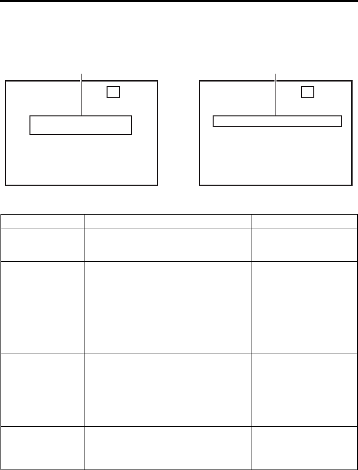
E-79
OTHERS
Warning display
When an error occurs, BR-HD50 automatically self-diagnoses the cause and displays an error-coded
warning message on the monitor.
If BR-HD50 is not in good order, or if an operation error has occurred, an alarm display will be shown on
the monitor.
Alarm display (Displayed regardless of the DISPLAY mode)
• For alarm displays resulting from operation errors, refer to page 24.
3DNIV2KCH–1/2 6PSM0
W
ARNING 7001
DRUM MOTOR FA I LURE
06 / 14 / 05 STANDBY
-
OFF
11:20:00 TCR 02:00:00:0
0
3MINDV 2K CH– 1 / 2 SP 6 0
HEAD CLEAN I NG REQU I RED !
06 / 10 / 05 STANDBY
-
OFF
11:20:00 TCR 02:00:00:00
Alarm displayWarning display
Display Status Action
LOW VOLTAGE The DC power voltage is low.
BR-HD50 will eventually go into the OPERATE
OFF mode if operation is continued.
Check the power voltage.
HEAD CLEANING
REQUIRED!
The video head is dirty. (This message is dis-
played when the DISPLAY mode is ON or
AUTO.) If the head is clogged, it will be
detected and the alarm message will be dis-
played in the PLAYBACK mode. The display
disappears when the cassette is ejected or the
head gets cleared of clog.
The message will also disappear when the
head cleaning tape is loaded.
Clean it with a JVC head-
cleaning tape. (XPage 9)
If the message persists
despite cleaning, it could be
due to bad recording condi-
tion, defective tape or head
lifespan.
OVER HEATING! The internal temperature of BR-HD50 has
exceeded the stated value.
Disconnect the power and
place BR-HD50 in a cool
place. If this message is dis-
played again, the unit may
have been damaged. In such
a case, consult your JVC
authorized dealer.
UNPLUG MAIN
POWER, PLUG
BACK IN AFTER A
WHILE
This is a system error that occurs when the
power is turned on. The OPERATE indicator on
BR-HD50 blinks in green. The unit will not
accept any operation commands.
Unplug the power cord from
the power outlet and wait for
some time before plugging it
back in.
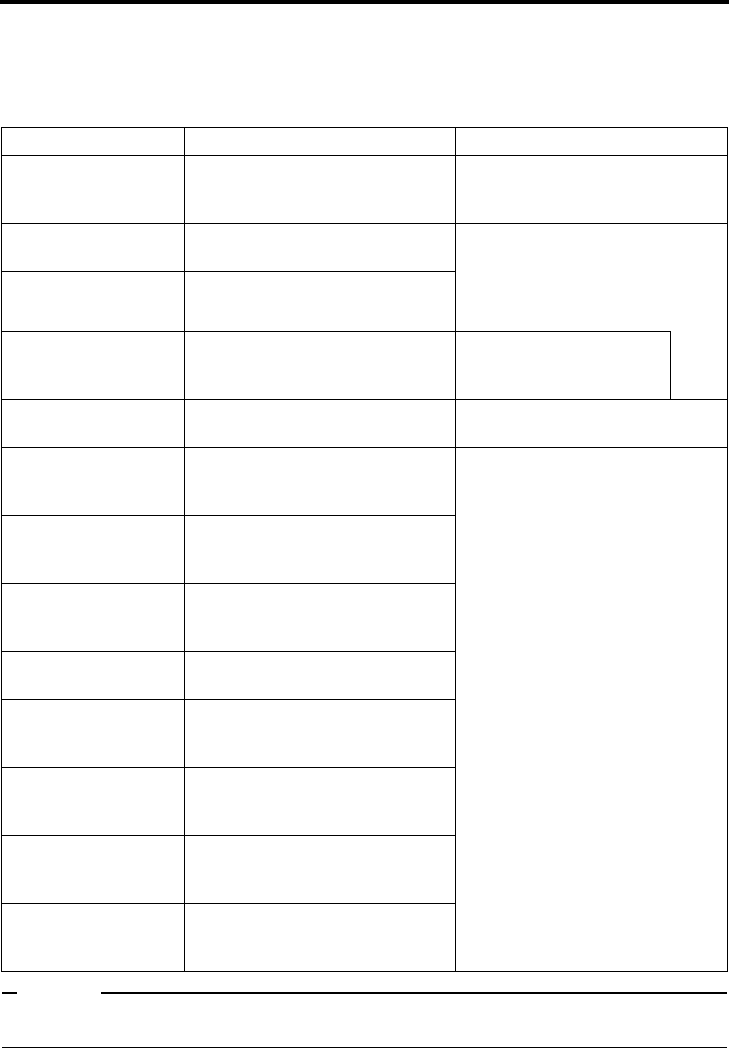
E-80
OTHERS
Warning display (continued)
Warning display (Displayed regardless of the DISPLAY mode)
When a warning display appears, BR-HD50 stops operation and ceases to accept any operation
command. When TAPE DEFECTIVE (5605 - 5609) is displayed, the unit similarly stops all opera-
tions except EJECT operation.
Memo
This unit uses a microcomputer. It may not function correctly if there is external noise. If this happens,
please turn off the power and then on again.
Display Status Action
WARNING 0201
CONDENSATION ON
DRUM
Condensation. Leave the power on and wait for the
display to disappear.
WARNING 3200
LOADING FAILURE
Unable to load tape. This error can be resolved by turning
off and then on the power. However,
doing so may damage the tape in
some cases. Consult your JVC
authorized dealer.
WARNING 3300
UNLOADING FAILURE
Unable to eject tape.
WARNING 4100
CASSETTE EJECT
FAILURE
Eject error. Is a heavy object on the unit?
DEFECTIVE TAPE!
5605 - 5609
Broken tape. Press the EJECT button to remove
and replace the tape.
WARNING 5702
TAPE END DET.
ERROR!
Tape-end sensor error. This error can be resolved by turning
off and then off the power. However,
doing so may damage the tape in
some cases. Consult your JVC
authorized dealer.
WARNING 5802
TAPE BEGIN DET.
ERROR!
Tape-beginning sensor error.
WARNING 7001
DRUM MOTOR
FAILURE
Drum rotation error.
WARNING 7101
CAP MOTOR FAILURE
Capstan rotation error.
WARNING 7202 - 7203
SUPPLY REEL
FAILURE
Supply reel rotation error.
WARNING 7302 - 7303
TAKE UP REEL
FAILURE
Take up reel rotation error.
WARNING 7305
TAKE UP REEL
FAILURE
Tape winding error during unloading.
WARNING 7401
REEL MOTOR
FAILURE
Reel motor rotation error.

E-81
OTHERS
Troubleshooting
Symptom Action
No power. Is the AC adapter correctly connected?
Unable to record. Is the slide of the cassette tape turned to “REC”?
Set it to “REC” if it is at the “SAVE” position.
The operation buttons of BR-HD50
do not work.
Is OPERATION LOCK of the SYSTEM [2/2] Menu set to ON?
Set it to OFF if the operation buttons are to be used.
For REMOTE, select the buttons that can be operated with the
LOCAL FUNCTION Menu.
Editing cannot be controlled even
after the REMOTE/LOCAL switch
is set to REMOTE.
To control with RS-422A, set REMOTE SEL 9P in the REMOTE
[1/2] Menu screen to “ON”.
Noise is produced on the playback
video.
Playback sound interrupted.
• The tape is damaged.
Replace the tape.
• The head is dirty.
Clean it with the specified head-cleaning tape. (XPage 9)
Cannot play back. Is the setting for PB TAPE FORMAT in the SYSTEM [2/2] Menu
screen something other than AUTO?
Playback is not available when this menu item does not match
the tape format.
Time codes are not correctly
recorded during DV signal input.
Is TC DUPLI. in the TC/UB/CLOCK [1/2] Menu screen correctly
set up?
Unable to turn on the power with
the OPERATE button.
Isn’t the REMOTE/LOCAL switch set to REMOTE when
LOCAL FUNCTION in the REMOTE [1/2] Menu screen is not
set to ALL KEYS?
SERIAL REMOTE control does not
function.
Isn’t REMOTE SEL SER in the REMOTE [1/2] Menu screen set
to OFF?
For SERIAL REMOTE control, set it to ON or LOC+REM.
Unable to operate BR-HD50 with
the IEEE1394 terminal.
• Isn’t REM SEL HDV/DV in the REMOTE [1/2] Menu screen
set to OFF? To operate with the IEEE1394 terminal, set it to
ON or LOC+REM.
• When the controlling equipment (non-linear editor, etc.) does
not recognize this unit, either reconnect the IEEE1394
cable, or reset the power to the unit.

E-82
OTHERS
Troubleshooting (continued)
Symptom Action
Cannot record HDV signals from
the IEEE1394 terminal.
• Is the IEEE1394 switch on the front panel set correctly?
To record HDV signals, set this to HDV.
• Is the HD signal format set correctly?
Match the 60/50 SEL setting in the SYSTEM [2/2] Menu
screen to the input HDV signal format. (XPage 40)
Cannot record DV signals from the
IEEE1394 terminal.
Is the IEEE1394 switch on the front panel set correctly?
To record DV signals, set this to DV.
No HD signal is output from the
HDMI OUT or COMPONENT OUT
terminal.
Is the HD signal format set correctly?
Match the 60/50 SEL setting in the SYSTEM [2/2] Menu screen
to the HD signal format. (XPage 40)
HDMI OUT terminal video does not
display on the monitor.
Is the monitor compatible with video from the HDMI OUT termi-
nal?
Check the monitor specifications.
To automatically set the HDMI OUT terminal video to the video
format for the connected equipment (monitor), set MONITOR
SELECT to HDMI[A] in the VIDEO Menu screen.
No signal is output from the
IEEE1394 terminal during play-
back.
• Is the IEEE1394 switch on the front panel set correctly?
Match the IEEE1394 switch setting to the playback tape
recording format.
• When playing a tape recorded in HDV format, check that the
HD signal format setting is correct. (XPage 40)
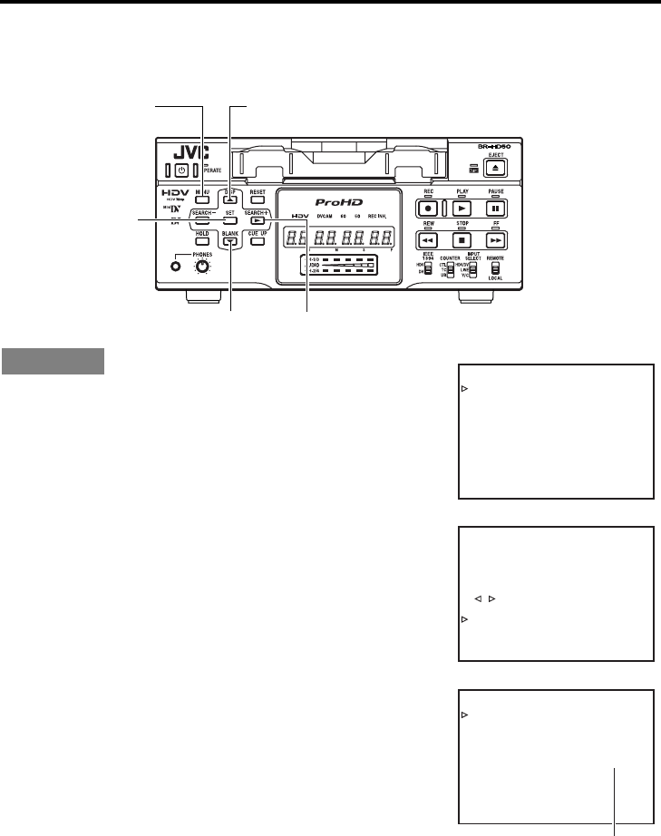
E-83
OTHERS
Checking the hour meter
This unit displays the drum usage time as the hour meter in DRUM HOUR METER in the SYSTEM [2/
2] Menu screen. Use it as a guide for regular maintenance. (XPage 8)
Use standard DV cassette tapes or mini DV cassette tapes.
Set BR-HD50 to the STOP mode:
1. Press the MENU button to display the TOP Menu screen.
2. Press the R or P button to bring the cursor to SYSTEM.
Press SET or the S button.
The SYSTEM [1/2] Menu screen is displayed.
3. Press the R or P button to bring the cursor to NEXT PAGE.
Press SET or the S button.
The SYSTEM [2/2] Menu screen is displayed.
• The drum usage time is displayed on DRUM HOUR METER in
the SYSTEM [2/2] Menu screen.
4. Press the MENU button to return to the normal screen.
Operation
R buttonMENU button
SET button
P button S button
TIXE
..TESYALPSID
..KCOLC/BU/CT
..OEDIV
..OIDUA
..ETOMER
..METSYS
–––UNEM––
–
KCABEGAP
EGAPTXEN
FFOEDOMTAEPER
VCER/RAV.CNUFYEK”,“
FFO-YBT
S
EDOMESUAPGNOL
CES30EMITESUAPGNOL
FFOVD:CER
NI5MEMITP. GNO LCER
PUKCAB
DN
2
D:VDA.F/LTS V
–––]2/1[METSYS––
–
–––SYSTEM [ 2 / 2 ] ––––––
DC I N MODE OPE OF F
INDEX WRITE INDEX
OPERAT I ON LOCK ON
60 / 50 SEL 60
FACTORY SETT I NG CANCEL
DRUM HOUR METER 0 0 0 2 0 0
PAGE BACK
Drum usage time
SYSTEM [1/2] Menu screen
TOP Menu screen
SYSTEM [2/2] Menu screen

E-84
OTHERS
Specifications
General
Power requirements
:DC 12 V W (from provided
AC adapter)
Power consumption
:DC 12 V W 26.4 W 2.2 A
Usable tape
:Standard/ mini DV cassette tape
Tape speed :18.8 mm/s
Record/play time
: 276 minutes (with LA-DV276PRO
tape)
63 minutes (with M-DV63PROHD
tape)
External dimension
:212 mm (W) × 88 mm (H) ×
327 mm (D) (Excluding pro-
truding parts)
Weight :Approx. 3.9 d
(Not including AC Adapter)
Allowable operating temperature
:5°C to 40°C
Allowable storage temperature
:–20°C to 60°C
Allowable operating humidity
:30% RH to 80% RH
Allowable storage humidity
:85% RH or less
Video
Recording format
:720/24p, 720/25p, 720/30p,
720/50p, 720/60p, 576/50p,
480/60p
(BR-HD50U/HD50E),
480/60i (BR-HD50U),
576/50i (BR-HD50E)
Video format :
[HDV]
Video signal recording format
:HDV720p format, 8-bit, 19.7
Mbps
Compression :MPEG-2 video (profile &
level: MP@H-14)
[DV]
Video signal recording format
:DV format, 8-bit, 25 Mbps
Compression :DV format, 4:1:1 (NTSC)/
4:2:0 (PAL)
Audio
[HDV]
Audio signal recording format
:MPEG1 Audio Layer II
[DV]
Audio signal recording format
:16-bit (locked audio), 48 kHz
PCM for 2 channels or 12-bit,
32 kHz PCM for 4 channels
Connectors
Video
[HDV]
Video outputs
Analog component
Y:1.0 V (p-p), 75 Ω (BNC)
PB/PR:0.7 V (p-p), 75 Ω (BNC)
[DV]
Video inputs
Analog composite:1.0 V (p-p), 75 Ω (BNC)
Analog Y/C
Y:1.0 V (p-p), 75 Ω
C:0.286 V (NTSC)/0.3 V (PAL)
(p-p), 75 Ω (4-pin)
Video outputs
Analog composite
:1.0 V (p-p), 75 Ω (BNC)
Analog Y/C
Y:1.0 V (p-p), 75 Ω
C:0.286 V (NTSC)/0.3 V (PAL)
(p-p), 75 Ω (4-pin)
Analog component
Y:1.0 V (p-p), 75 Ω (BNC)
PB/PR:0.7 V (p-p), 75 Ω (BNC)
Audio
Audio inputs
Line :–8 dBs, 10 kΩ unbalanced
(RCA)
Audio outputs
Line
: –8 dBs, 1 k
Ω
unbalanced (RCA)
Headphones :– ∞ to – 15 dBs, 8 Ω (Stereo
mini Jack)
HDMI output :Type A (19-pin)
IEEE1394 interface
:6-pin
RS-422 interface :D-sub-9pin
Serial remote interface
:Mini jack
AC adapter
Input :AC 100 V – 240 V D,
50 Hz/60 Hz 1.7 A
Output :DC 12 V W 4.6 A
Accessories
AC adapter .................................................... × 1
Power cord (for BR-HD50U) ......................... × 1
Power cord (for BR-HD50E) ......................... × 2
Ferrite core (for IEEE1394 cable) ................. × 1
Ferrite core (for DC cord) .............................. × 1
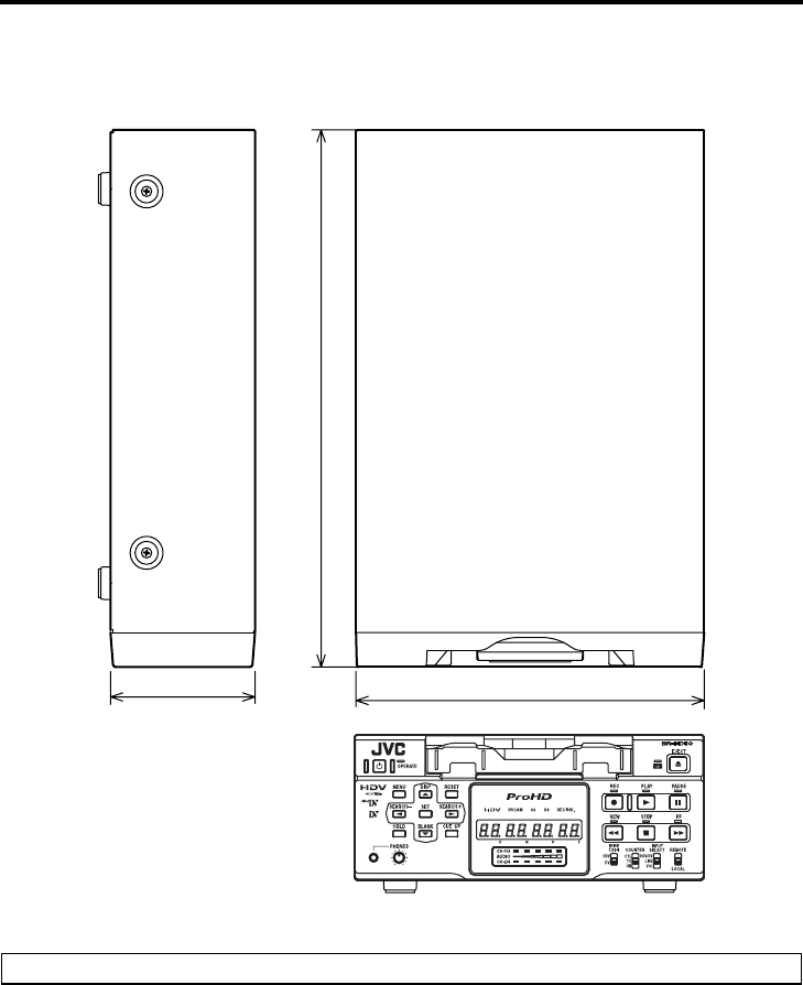
E-85
External dimensions (Unit: mm)
212
327
88
For improvement, the specifications and external appearance may be changed without prior notice.

E-86
OTHERS
Supplement
AC adapter section
IMPORTANT SAFETY INSTRUCTIONS
1) Read these instructions.
2) Keep these instructions.
3) Heed all warnings.
4) Follow all instructions.
5) Do not use this apparatus near water.
6) Clean only with dry cloth.
7) Do not block any ventilation openings. Install in accordance with the manufacturer’s instructions.
8) Do not install near any heat sources such as radiators, heat registers, stoves, or other apparatus
(including amplifiers) that produce heat.
9) Do not defeat the safety purpose of the polarized or grounding-type plug. A polarized plug has two
blades with one wider than the other. A grounding type plug has two blades and a third grounding
prong. The wide blade or the third prong are provided for your safety. If the provided plug does not
fit into your outlet, consult an electrician for replacement of the obsolete outlet.
10) Protect the power cord from being walked on or pinched particularly at plugs,
convenience receptacles, and the point where they exit from the apparatus.
11) Only use attachments/accessories specified by the manufacturer.
12) Use only with the cart, stand, tripod, bracket, or the table specified by the
manufacturer, or sold with the apparatus.
When a cart is used, use caution when moving the cart/apparatus combina-
tion to avoid injury from tip-over.
13) Unplug this apparatus during lightning storms or when unused for long peri-
ods of time.
14) Refer all servicing to qualified service personnel. Servicing is required when the apparatus has
been damaged in any way, such as power-supply cord or plug is damaged, liquid has been spilled
or objects have fallen into the apparatus, the apparatus has been exposed to rain or moisture, does
not operate normally, or has been dropped.
WARNING – To reduce the risk of fire or electric shock, do not expose this apparatus to rain or mois-
ture.
Apparatus shall not be exposed to dripping or splashing and no objects filled with liquids, such as
vases, shall be placed on the apparatus.
CAUTION – These servicing instructions are for use by qualified service personnel only. To reduce the
risk of electric shock, do not perform any servicing other than that contained in the operat-
ing instructions unless you are qualified to do so.

BR-HD50 HD VIDEO CASSETTE RECORDER
BR-HD50
E
HD VIDEO CASSETTE RECORDER
INSTRUCTION MANUAL
(A)
LLT0088-001C
Thank you for purchasing this JVC product.
Before operating this unit, please read the
instructions carefully to unsure the best possi-
ble performance.
For Customer Use:
Enter below the Serial No. which is
located on the rear of cabinet. Retain
this information for future reference.
Model No. BR-HD50U/BR-HD50E
Serial No.
2008 Victor Company of Japan, Limited LLT0088-001C
