JVC DLA VS4010 / VS4810 User Manual VS4010, B5A 2460 00
DLA-VS4810 DLA-VS4810 B5A-2460-00 English, Instruction manual
User Manual: JVC DLA-VS4010 DLA-VS4010, DLA-VS4810 English, Instruction manual
Open the PDF directly: View PDF ![]() .
.
Page Count: 64
.
D-ILA
PROJECTOR
DLA-VS4010
DLA-VS4810
.
Thank you for purchasing this JVC product.
Please study this instruction manual carefully before starting to
operate the unit, in order to use the unit correctly.
We take no responsibility for any problems resulting from misuse
of this unit by operating this equipment other than instructed in this
manual.
INSTRUCTIONS
B5A-2460-00
For Customer use :
Enter below the serial No. which is
located on the side of the cabinet.
Retain this information for future
reference.
DLA-VS4010 /
DLA-VS4810
Model No.
Serial No.
Getting Started
Connection and Installation
Network Settings
Operation and Settings
Others
Safety Precautions
.
IMPORTANT INFORMATION
WARNING:
TO PREVENT FIRE OR SHOCK HAZARDS, DO
NOT EXPOSE THIS APPLIANCE TO RAIN OR
MOISTURE.
About the installation place
Do not install the projector in a place that cannot
support its weight securely.
If the installation place is not sturdy enough, the
projector could fall or overturn, possibly causing
personal injury.
WARNING:
THIS APPARATUS MUST BE EARTHED.
CAUTION:
To reduce the risk of electric shock, do not remove
cover. Refer servicing to qualified service personnel.
This projector is equipped with a 3-blade grounding
type plug to satisfy FCC rule. If you are unable to
insert the plug into the outlet, contact your electrician.
MACHINE NOISE INFORMATION (Germany
only)
Changes Machine Noise Information Ordinance 3.
GSGV, January 18, 1991: The sound pressure level
at the operator position is equal or less than 70 dB
(A) according to ISO 7779.
FCC INFORMATION (U.S.A. only)
CAUTION:
Changes or modification not approved by JVC could
void the user’s authority to operate the equipment.
NOTE:
This equipment has been tested and found to
comply with the limits for a Class A digital device,
pursuant to Part 15 of the FCC Rules. These limits
are designed to provide reasonable protection
against harmful interference when the equipment is
operated in a commercial environment. This
equipment generates, uses, and can radiate radio
frequency energy and, if not installed and used in
accordance with the instruction manual, may cause
harmful interference to radio communications.
Operation of this equipment in a residential area is
likely to cause harmful interference in which case
the user will be required to correct the interference
at his own expense.
PORTABLE CART WARNING
(symbol provided by RETAC)
S3126A
-
-
-
-
-
-
-
-
-
-
-
-
IMPORTANT SAFEGUARDS
Electrical energy can perform many useful functions.
This unit has been engineered and manufactured to
assure your personal safety. But IMPROPER USE
CAN RESULT IN POTENTIAL ELECTRICAL
SHOCK OR FIRE HAZARD. In order not to defeat
the safeguards incorporated into this product,
observe the following basic rules for its installation,
use and service. Please read these Important
Safeguards carefully before use.
All the safety and operating instructions should be
read before the product is operated.
The safety and operating instructions should be
retained for future reference.
All warnings on the product and in the operating
instructions should be adhered to.
All operating instructions should be followed.
Place the projector near a wall outlet where the plug
can be easily unplugged.
Unplug this product from the wall outlet before
cleaning.
Do not use liquid cleaners or aerosol cleaners. Use
a damp cloth for cleaning.
Do not use attachments not recommended by the
product manufacturer as they may be hazardous.
Do not use this product near water. Do not use
immediately after moving from a low temperature to
high temperature, as this causes condensation,
which may result in fire, electric shock, or other
hazards.
Do not place this product on an unstable cart, stand,
or table. The product may fall, causing serious injury
to a child or adult, and serious damage to the
product. The product should be mounted according
to the manufacturer’s instructions, and should use a
mount recommended by the manufacturer.
When the product is used on
a cart, care should be taken to
avoid quick stops, excessive
force, and uneven surfaces
which may cause the product
and cart to overturn, damaging
equipment or causing possible
injury to the operator.
Slots and openings in the cabinet are
provided for ventilation. These ensure reliable
operation of the product and protect it from
overheating. These openings must not be blocked
or covered. (The openings should never be blocked
by placing the product on bed, sofa, rug, or similar
surface. It should not be placed in a built-in
installation such as a bookcase or rack unless
proper ventilation is provided and the
manufacturer’s instructions have been adhered to.)
For proper ventilation, separate the product from
other equipment, which may prevent ventilation and
keep a distance.
2
Getting Started

.
-
-
-
-
-
-
-
-
-
a)
b)
c)
d)
e)
f)
When the power supply cord or plug is damaged.
If liquid has been spilled, or objects have fallen
on the product.
If the product has been exposed to rain or water.
If the product does not operate normally by
following the operating instructions. Adjust only
those controls that are covered by the Operation
Manual, as an improper adjustment of controls
may result in damage and will often require
extensive work by a qualified technician to
restore the product to normal operation.
If the product has been dropped or damaged in
any way.
When the product exhibits a distinct change in
performance, this indicates a need for service.
This product should be operated only with the type
of power source indicated on the label. If you are not
sure of the type of power supply to your home,
consult your product dealer or local power company.
This product is equipped with a three-wire plug. This
plug will fit only into a grounded power outlet. If you
are unable to insert the plug into the outlet, contact
your electrician to install the proper outlet. Do not
defeat the safety purpose of the grounded plug.
The lens for this product is optional. Do not attach
the power cord when the lens is not attached.
Turning on the power when no lens is attached may
result in fire, electric shock, or other hazards.
Power-supply cords should be routed so that they
are not likely to be walked on or pinched by items
placed upon or against them. Pay particular
attention to cords at doors, plugs, receptacles, and
the point where they exit from the product.
For added protection of this product during a
lightning storm, or when it is left unattended and
unused for long periods of time, unplug it from the
wall outlet and disconnect the cable system. This
will prevent damage to the product due to lightning
and power line surges.
Do not overload wall outlets, extension cords, or
convenience receptacles on other equipment as this
can result in a risk of fire or electric shock.
Never push objects of any kind into this product
through openings as they may touch dangerous
voltage points or short out parts that could result in a
fire or electric shock. Never spill liquid of any kind on
the product.
Do not attempt to service this product yourself as
opening or removing covers may expose you to
dangerous voltages and other hazards. Refer all
service to qualified service personnel.
Unplug this product from the wall outlet and refer
service to qualified service personnel under the
following conditions:
-
-
-
-
-
-
-
-
-
-
-
When replacement parts are required, be sure the
service technician has used replacement parts
specified by the manufacturer or with same
characteristics as the original part. Unauthorized
substitutions may result in fire, electric shock, or
other hazards.
Upon completion of any service or repairs to this
product, ask the service technician to perform safety
checks to determine that the product is in proper
operating condition.
The product should be placed more than one foot
away from heat sources such as radiators, heat
registers, stoves, and other products (including
amplifiers) that produce heat.
When connecting other products such as VCR’s,
and DVD players, you should turn off the power of
this product for protection against electric shock.
Do not place combustibles behind the cooling fan.
For example, cloth, paper, matches, aerosol cans or
gas lighters that present special hazards when over
heated.
Do not look into the projection lens while the
illumination lamp is turned on. Exposure of your
eyes to the strong light can result in impaired
eyesight.
Do not look into the inside of this unit through vents
ventilation holes), etc. Do not look at the illumination
lamp directly by opening the cabinet while the
illumination lamp is turned on. The illumination lamp
also contains ultraviolet rays and the light is so
powerful that your eyesight can be impaired.
Do not drop, hit, or damage the light-source lamp
lamp unit) in any way. It may cause the light-source
lamp to break and lead to injuries. Do not use a
damaged light source lamp. If the light-source lamp
is broken, ask your dealer to repair it. Fragments
from a broken light-source lamp may cause injuries.
The light-source lamp used in this projector is a high
pressure lamp. Be careful when disposing of the
lightsource lamp. If anything is unclear, please
consult your dealer.
Do not ceiling-mount the projector to a place which
tends to vibrate; otherwise, the attaching fixture of
the projector could be broken by the vibration,
possibly causing it to fall or overturn, which could
lead to personal injury.
Use only the accessory cord designed for this
product to prevent shock.
* DO NOT allow any unqualified person to
install the unit.
Be sure to ask your dealer to install the unit
(e.g.attaching it to the ceiling) since special
technical knowledge and skills are required for
installation. If installation is performed by an
unqualified person, it may cause personal injury or
electrical shock.
3
Getting Started
.
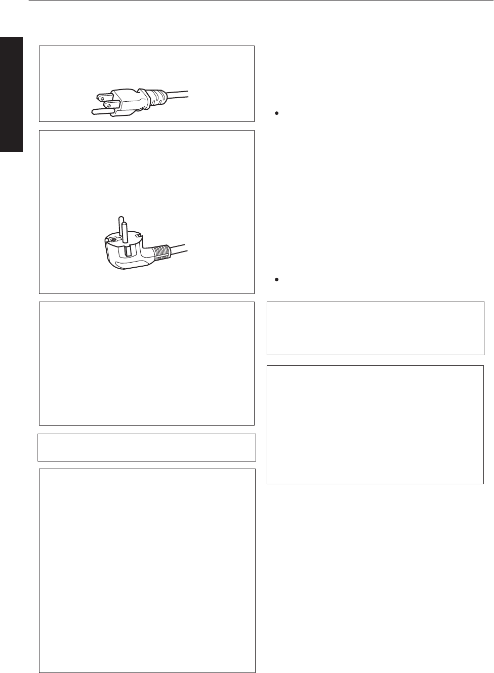
Power cord
Power cord
For European continent countries
Green-and-yellow
Blue
Brown
: Earth
: Neutral
: Live
POWER CONNECTION
WARNING:
WARNING:
Do not cut off the main plug from this equipment.
The power supply voltage rating of this product is
AC100V – AC240V. Use only the power cord
designated by our dealer to ensure Safety and EMC.
Ensure that the power cable used for the projector is
the correct type for the AC outlet in your country.
Consult your product dealer.
If the plug fitted is not suitable for the power points
in your home or the cable is too short to reach a
power point, then obtain an appropriate safety
approved extension lead or adapter or consult your
dealer. If nonetheless the mains plug is cut off,
dispose of the plug immediately, to avoid a possible
shock hazard by inadvertent connection to the main
supply. If a new main plug has to be fitted, then
follow the instruction given below.
THIS APPARATUS MUST BE EARTHED.
IMPORTANT (Europe only):
The wires in the mains lead on this product are
colored in accordance with the following cord:
As these colors may not correspond with the
colored making identifying the terminals in your
plug, proceed as follows:
The wire which is colored green-and-yellow must be
connected to the terminal which is marked M with
the letter E or the safety earth or colored green or
green-and-yellow. The wire which is colored blue
must be connected to the terminal which is marked
with the letter N or colored black.
The wire which is colored brown must be connected
to the terminal which is marked with the letter L or
colored red.
For USA and Canada only
Use only the following power cord.
Cables
Power cord
DVI (X4) Cable
USB Cable
LAN Cable
RS-232C Cable
Power supply cord
Shielded cable
Shielded cable
Shielded cable
Shielded cable
Length
3.3 m
5.0 m
2.0 m
2.0 m
1.6 m
EMC Supplement
WARNING:
This equipment is compliant with Class A of CISPR 32.
In residential environment this equipment may cause
radio interference.
Dear Customer,
This apparatus is in conformance with the valid
European directives and standards regarding
electromagnetic compatibility and electrical safety.
European representative of
JVC KENWOOD Corporation is:
JVCKENWOOD Deutschland GmbH
Konrad-Adenauer-Allee 1-11,
61118 Bad Vilbel,
GERMANY
-This equipment is in conformity with the provisions
and protection requirements of the corresponding
European Directives.
This equipment is designed for professional rojector
appliances and can be used in the following
environments.
In order to keep the best performance and
furthermore for electromagnetic compatibility we
recommend to use the cables not exceeding the
following length:
Controlled EMC environment (for example
purpose built broadcasting or recording studio),
and the rural outdoors environment (far away from
railways, transmitters, overhead power lines, etc).
The inrush current of this apparatus is 11.945
amperes.
4
Getting Started
.
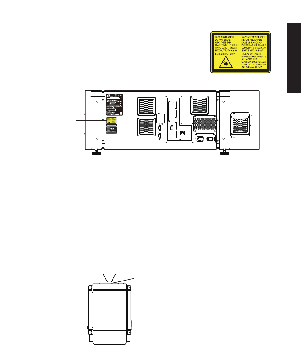
For the customers In the U.S.A. and Canada
CAUTION
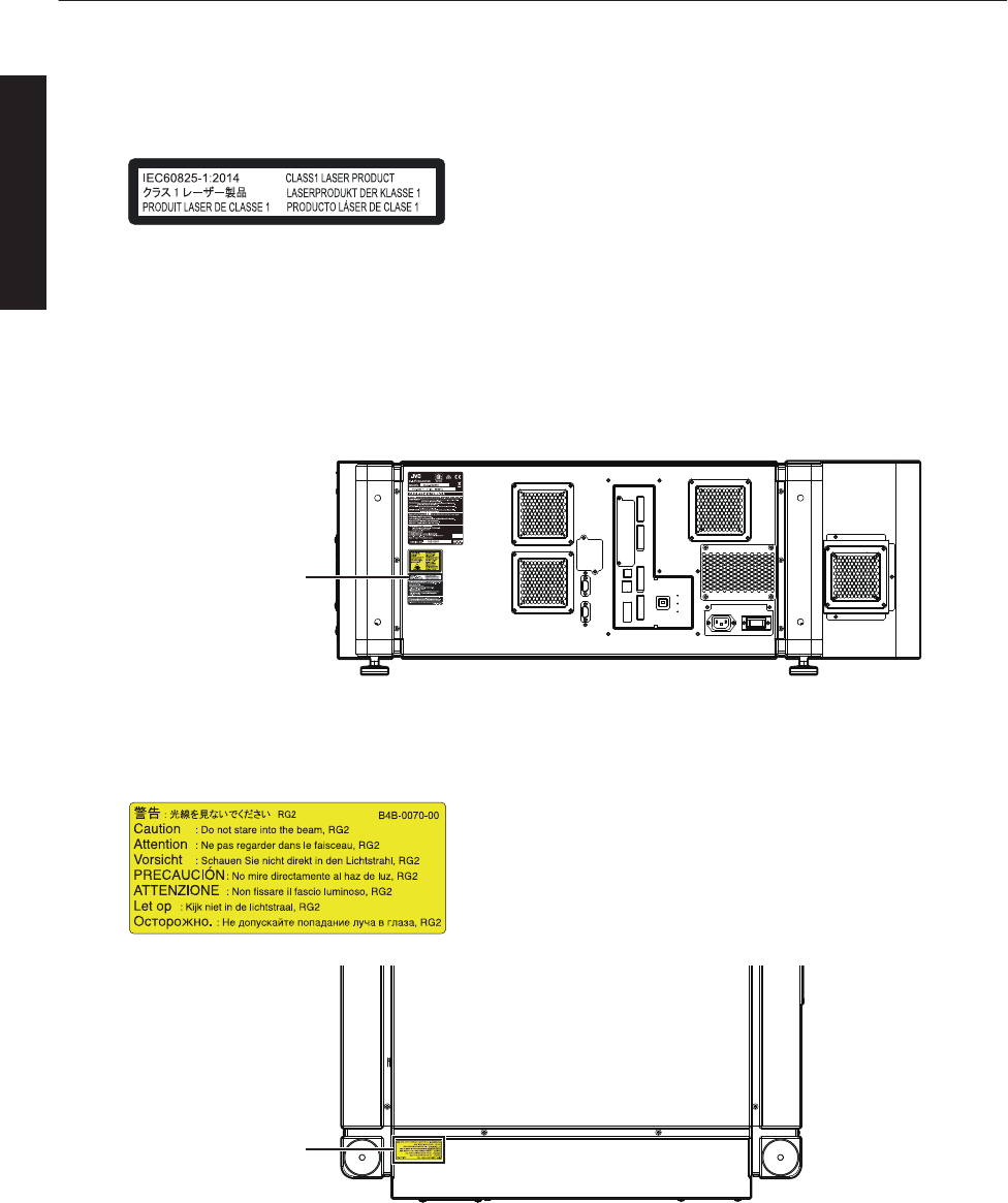
Location information of the labels
LASER RADIATION
DO NOT STARE INTO THE BEAM
CLASS 2 LASER PRODUCT
Do not look into the lens while in use.
Light source specifications
30 W Laser diodes ×12
Wavelength 450 - 460 nm
Maximum output is 49.2 W
WARNING
Beam divergence angle from lens of this unit
Laser emission port
Wide : α=25.9°
Tele : α=15.4°
α
CAUTION
Use of controls or adjustments or performance of procedures other than those
specified herein may result in hazardous radiation exposure.
This Projector is classified as a CLASS 2 LASER PRODUCT.
This CLASS 2 LASER PRODUCT label and Caution label is located on the
Rear Side surface of the projector.
LASER CAUTION
LABEL
5
Getting Started
.
Use of controls or adjustments or performance of procedures other than those specified herein may result in
hazardous radiation exposure.
For the customers In other countries
CLASS 1 LASER PRODUCT
Location information of the labels
Do not look into the lens while in use.
WARNING
CAUTION
LASER CAUTION LABEL
IEC62471-5
RG LABEL
As with any bright light source, do not stare into the beam, RG2 IEC 62471-5:2015
LASER CAUTION
LABEL
RG LABEL
6
Getting Started
.
ENGLISH
Information for Users on Disposal of Old Equipment and Batteries
[European Union only]
These symbols indicate that equipment with these symbols should not be disposed
of as general household waste. If you want to dispose of the product or battery,
please consider the collection systems or facilities for appropriate recycling.
Notice:
The sign Pb below the symbol for batteries indicates that this battery contains lead.
Benutzerinformationen zur Entsorgung alter Geräte und Batterien
[Nur Europäische Union]
Diese Symbole zeigen an, dass derartig gekennzeichnete Geräte nicht als normaler
Haushaltsabfall entsorgt werden dürfen. Wenden Sie sich zur Entsorgung des
Produkts oder der Batterie an die hierfür vorgesehenen Sammelstellen oder
Einrichtungen, damit eine fachgerechte Wiederverwertung möglich ist.
Hinweis:
Notification:
Das Zeichen Pb unterhalb des Batteriesymbols gibt an, dass diese
Batterie Blei enthält.
Informations relatives à l’élimination des appareils et des piles usagés, à l’intention des utilisateurs
[Union européenne seulement]
Si ces symboles figurent sur les produits, cela signifie qu’ils ne doivent pas être jetés
comme déchets ménagers. Si vous voulez jeter ce produit ou cette pile, veuillez
considérer le système de collecte des déchets ou les centres de recyclage appropriés.
La symbole Pb en dessous du symbole des piles indique que cette
pile contient du plomb.
Informatie voor gebruikers over het verwijderen van oude apparatuur en batterijen
[Alleen Europese Unie]
Deze symbolen geven aan dat apparatuur met dit symbool niet mag worden
weggegooid als algemeen huishoudelijk afval. Als u het product of de batterij wilt
weggooien, kunt u inzamelsystemen of faciliteiten voor een geschikte recycling
gebruiken.
Opmerking:
Het teken Pb onder het batterijsymbool geeft aan dat deze batterij lood bevat.
Battery
Products
Batterie
Produkte
Pile
Produits
Batterij
Producten
DEUTSCH
FRANÇAIS
NEDERLANDS
Información para los usuarios sobre la eliminación de baterías/pilas usadas
[Sólo Unión Europea]
Estos símbolos indican que el equipo con estos símbolos no debe desecharse
con la basura doméstica. Si desea desechar el producto o batería/pila, acuda
a los sistemas o centros de recogida para que los reciclen debidamente.
Atención: La indicación Pb debajo del símbolo de batería/pila indica que ésta
contiene plomo.
Baterías/pilas
Productos
ESPAÑOL / CASTELLANO
ITALIANO
Informazioni per gli utenti sullo smaltimento delle apparecchiature e batterie obsolete
[Solo per l’Unione Europea]
Questi simboli indicano che le apparecchiature a cui sono relativi non devono
essere smaltite tra i rifiuti domestici generici. Se si desidera smaltire questo
prodotto o questa batteria, prendere in considerazione i sistem i o le strutture di
raccolta appropriati per il riciclaggio corretto.
Nota:
Il simbolo Pb sotto il simbolo delle batter ie indica che questa batteria contiene piombo.
Batteria
Prodotti
7
Getting Started
Contents
Getting Started
Safety Precautions .................................................. 2
Names and Functions of Parts ................................ 9
Front/Right, Left and Rear Side ........................... 9
Right Side .......................................................... 10
Connection and Installation
Installation ............................................................. 11
Optional Projection Lens .................................... 11
Minimum Space Required ................................. 11
Projector Installation Angle ................................ 12
Installing the Projector and Screen ........................ 13
Screen Size and Projection Distance ................. 16
Connecting Video Signals of the Computer ........... 18
Connection During Single-Screen Mode Display
........................................................................... 18
Connection During Two-Screen/Four-Screen Mode
Display ............................................................... 20
Network Settings
Connection Using a LAN Cable ............................. 22
Connection Example ......................................... 22
Specifications of PC for Controlling this Projector
........................................................................... 23
Turning On the Main Power ................................... 24
IP Address Settings ............................................... 25
Assigning a static IP address ............................. 25
Assigning IP Address from the DHCP Server .... 28
Using the Mail Delivery Feature ............................. 28
Connection Example (When DHCP Server is
Used) ................................................................. 28
Operation and Settings
Projecting Image ................................................... 29
Useful Features During Projection ..................... 32
Displaying the Menu .............................................. 33
User Settings Menu ............................................... 34
User Settings Menu Structure ............................ 34
(1) Main Menu ................................................... 35
(2) Image Menu ................................................. 37
(3) Setting Menu ................................................ 38
(4) Convergence Menu ...................................... 39
(5) Lens Menu ................................................... 40
(6) Option Menu ................................................. 41
Administrator Settings Menu ................................. 42
Administrator Settings Menu Structure .............. 42
(7) Admin.Network Menu ................................... 43
(8) Admin.E-mail Menu ...................................... 45
(9) Admin.Option Menu ..................................... 47
(10) Admin.Signal Menu .................................... 48
Others
Troubleshooting .................................................... 50
What to do when these messages are displayed .. 52
Warnings Using Indicators .................................... 53
Warning Status ...................................................... 54
RS-232C Interface ................................................ 55
Communication Specifications .......................... 55
Command Format .............................................. 55
Maintenance ......................................................... 57
Cleaning and Replacing the Filter ...................... 57
Routine Servicing .............................................. 59
Specifications ........................................................ 60
Dimensional Outline Drawing ............................ 63
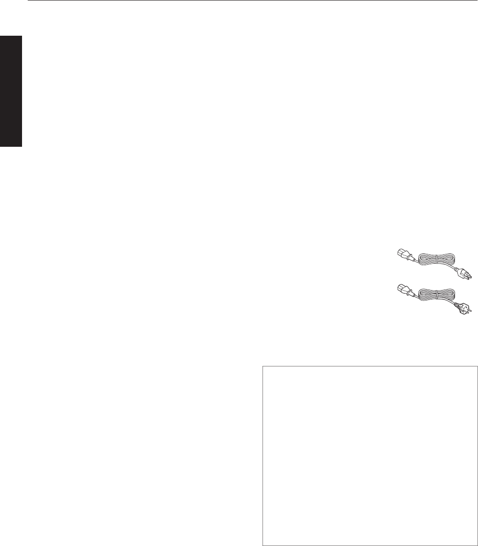
Accessories
Power cord (for USA)
(about. 3.3 m)
....................................... 1 piece .
Power cord (for EU)
(about. 3.3 m)
....................................... 1 piece .
Plug Holder ................... 1 piece
0Other items include the instruction manual, warranty,
and other printed materials.
Content of this manual
0Personal computers or computers are expressed as
computers or PCs in this manual.
0Contents of this manual are the copyright of JVC. All
rights reserved.Unauthorized reproduction and
duplication of this manual, in whole or in part,
without the permission of JVC is strictly prohibited.
0The names of other companies’ products that
appear in this manual are the trademark or
registered trademark of the respective
companies.Symbols such as ™, ®, and © are
omitted in this manual.
0Designs, specifications, and other details described
in this manual may be modified for improvement
without prior notice.
8
Getting Started
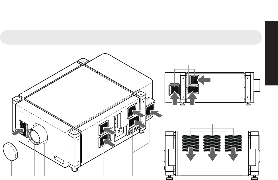
Names and Functions of Parts
Front/Right, Left and Rear Side
.
BCD E F F
F
G
A
Exhaust air
Intake air
Intake air
Intake air
Intake air
Intake air
AAir Inlet/Filter
The air inlets absorb air to cool the interior of the
projector. A filter is mounted inside the projector to
remove dirt in the air that enters through the inlets.
Clean the filter regularly. (P. 57)
0Do not block the air inlets with papers, cloth, or soft
cushions. Doing so may cause heat to trap inside the
projector and result in fire or malfunction.
BLens Cap (included with the
optional lens)
Fit the cap on the lens when this projector is not in use
to prevent the lens from becoming dirty.
0Do not project images with the lens cap attached. The
lens cap may be deformed due to the heat, or the
projector may malfunction.
CProjection Lens (optional)
Zoom lens or short focal length lens is optional.
(P. 60)
Remove the lens cap before projection.
DLens Mounting Bracket
Mount the optional projection lens.
EAdjustable Feet (x4)
Adjust the feet until the projector is level. The
adjustable range is 20 mm for each. (P. 12)
FAir Inlet/Filter
(Right Side: x5, Left Side: x3)
The air inlets absorb air to cool the interior of the
projector. A filter is mounted inside the projector to
remove dirt in the air that enters through the inlets.
Clean the filter regularly. (P. 57)
GVent Hole
Warm air exits from the hole after cooling the projector.
0Do not block the vent holes with papers, cloth, or soft
cushions. Doing so may cause heat to trap inside the
projector and result in fire or malfunction.
9
Getting Started
Right Side
.
OPERATE I/B
DVI 3
USB
LAN
RS-232C
STANDBY/ON
LAMP
WARNING
DVI 4
DVI 1
DVI 2
e-shift Sync
RS-232C
1
2
R
Q
KJ LM N P
O S T
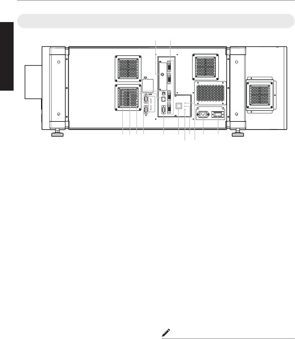
IH
H[e-shift Sync] Terminal
(DLA-VS4810 only)
This is the input terminal for e-shift sync signals.
I[DVI 1 to 4] Terminal
This is an input terminal for video signals. Connect it
to the video output terminal of the computer. (P. 19,
21)
J[USB] Terminal
Enables control of this projector by connecting it to a
computer.
K[LAN] Terminal
Enables control of this projector using a computer that
is connected to the network.
L[RS-232C 1] Terminal
M[RS-232C 2] Terminal
N[RS-232C] Terminal
This is the RS-232C interface-specific terminal. This
projector can be controlled by connecting it to a
computer using a RS-232C cable.
O[OPERATE Z] Button
Pressing this button for one second or longer when in
the standby mode (main power supply is ON) turns on
the power of the projector unit. Pressing it for one
second or longer when the power is ON switches the
projector to the standby mode.
P[WARNING] Indicator
This indicator lights up in red when abnormality occurs
on this projector.
0For details, refer to “Warnings Using
Indicators”P. 53.
Q[LAMP] Indicator
This indicator lights up in yellow when the lifetime of
the LD block exceeds 19,000 hours.
0For details, refer to “Warnings Using
Indicators”P. 53.
0A message on the LD block lifespan appears when the
lifetime of the LD block has exceeded 20,000 hours.
(P. 52)
R[STANDBY/ON] Indicator
Lit (Red) : When in the standby mode.
Lit (Green) : When power is supplied.
Blinking (Red) : When cooling down (cool down
mode). (P. 31)
Blinking (Green) : When the projected image is
temporarily hidden. (P. 32)
0For details, refer to “Warnings Using
Indicators”P. 53.
SAC Power Input Terminal
Connect the supplied cord to this terminal.
TMain Power Supply Switch
Use this to turn ON/OFF the main power supply of the
projector unit.
MEMO
0A stand-BY condition is indicated by the symbol B.
0Power ON condition is indicated by the symbol C.
0Power OFF condition is indicated by the symbol X.
10
Getting Started
Installation
Please read the following carefully when installing this unit.
Optional Projection Lens
Mount the optional projection lens (P. 60). For details on mounting the lens, please consult your authorized dealer.
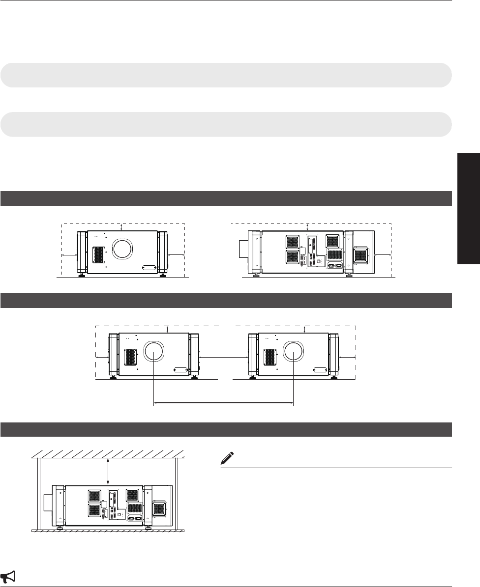
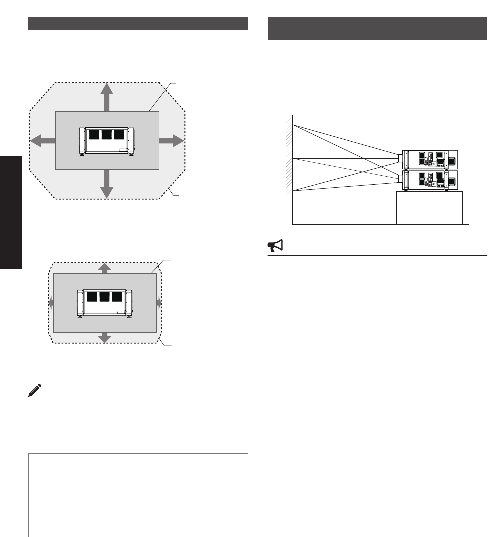
Minimum Space Required
Do not use a cover that may enclose this unit or block the air inlets/vent holes. Allow sufficient space around this unit.
When this unit is enclosed in a space with dimensions as indicated below, ventilate accordingly so that the internal and
external temperatures are the same.
When using one set of projector
.
OPERATE I/B
DVI 3
USB
LAN
RS-232C
STANDBY/ON
LAMP
WARNING
DVI 4
DVI 1
DVI 2
e-shift Sync
RS-232C
1
2
300 mm
600 mm 600 mm 600 mm
300 mm
When using two sets of projectors side by side
.
300 mm
1300 mm
640 mm
600 mm 600 mm
300 mm
When the projector is suspended
MEMO
0To prevent the projector from falling or toppling, it is
recommended that the holder be fastened to the unit using
bolts.
0To mount the projector to the ceiling, mount a special shelf
to the ceiling, followed by installing the unit on the shelf.
For safety and maintenance purposes, equipment that
eases adjustment to a suitable height for maintenance is
required.
CAUTION
0Special expertise and techniques are required for mounting this unit. Be sure to ask your dealer or a specialist to
perform mounting.
OPERATE I/B
DVI 3
USB
LAN
RS-232C
STANDBY/ON
LAMP
WARNING
DVI 4
DVI 1
DVI 2
e-shift Sync
RS-232C
1
2
300 mm and
above
11
Connection and Installation
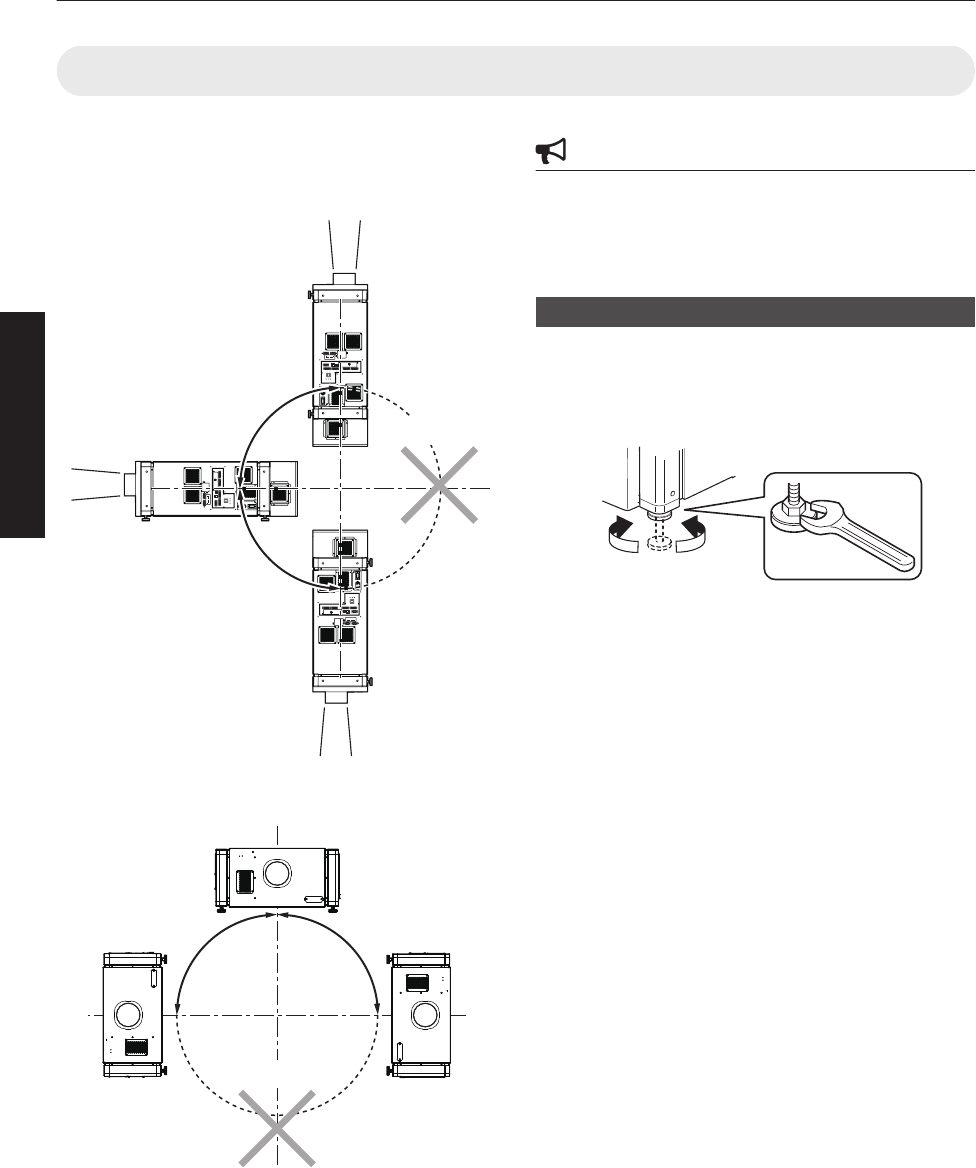
Projector Installation Angle
You can install this projector between ±90° both vertically
and horizontally.
Vertical Angle
.
OPERATE I/B
DVI 3
USB
LAN
RS-232C
STANDBY/ON
LAMP
WARNING
DVI 4
DVI 1
DVI 2
e-shift Sync
RS-232C
1
2
OPERATE I/B
DVI 3
USB
LAN
RS-232C
STANDBY/ON
LAMP
WARNING
DVI 4
DVI 1
DVI 2
e-shift Sync
RS-232C
1
2
OPERATE I/B
DVI 3
USB
LAN
RS-232C
STANDBY/ON
LAMP
WARNING
DVI 4
DVI 1
DVI 2
e-shift Sync
RS-232C
1
2
+90°
-90°
*Not applicable
Horizontal Angle
.
+90°
-90°
*Not applicable
CAUTION
0Special expertise and techniques are required for
mounting this unit. Be sure to ask your dealer or a
specialist to perform mounting.
0The projector cannot be installed upside down.
Adjusting the Inclination
Adjust the horizontal angle of the projector.
Lift the projector and turn the nut of the adjustable foot
with a spanner in the direction indicated by the arrow to
extend or retract the foot. The adjustable range is 20 mm.
.
RetractExtend
12
Connection and Installation
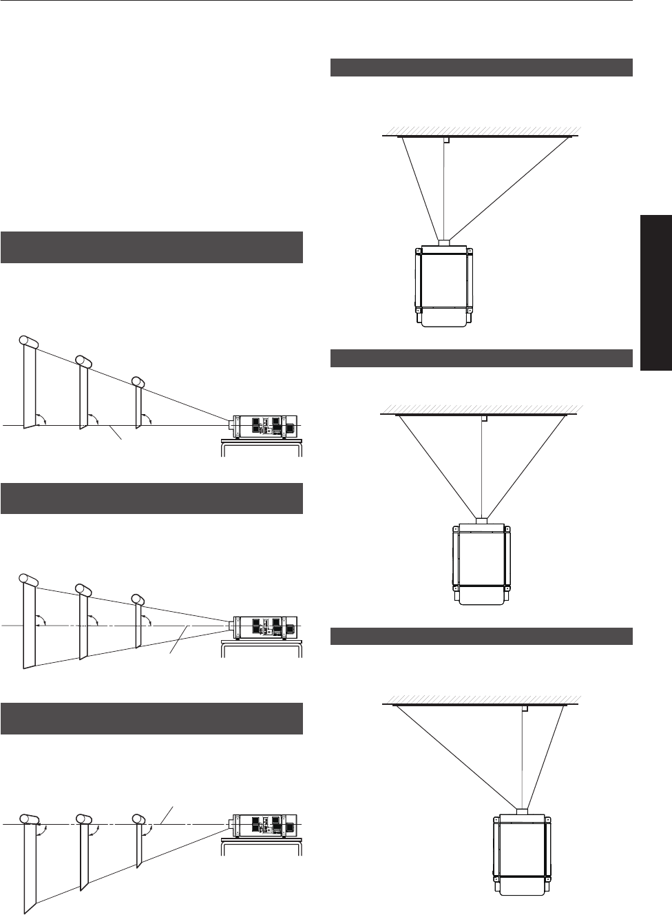
Installing the Projector and Screen
It is recommended that this projector be installed at right
angle to the screen.
When a zoom lens (optional) is in use, you can make use
of the lens shift feature of this projector to shift the
projection screen vertically between 0% to ±50%, and
horizontally between 0% to ±25%.
When a short focal length lens (optional) is in use, you
can shift the projection screen position vertically between
0% to ±15%, and horizontally between 0% to ±5%.
Below are some examples on the layout when a zoom
lens is used.
When shift amount in the upward direction is
+50 %
Install the projector such that the lower end of the
projection screen is at the same height as the center of
the lens.
.
OPERATE I/B
DVI 3
USB
LAN
RS-232C
STANDBY/ON
LAMP
WARNING
DVI 4
DVI 1
DVI 2
e-shift Sync
RS-232C
1
2
Center Line of Lens
90°90° 90°
Screen
When shift amount in the upward/downward
direction is 0 %
Install the projector such that the center of the projection
screen is at the same height as the center of the lens.
.
OPERATE I/B
DVI 3
USB
LAN
RS-232C
STANDBY/ON
LAMP
WARNING
DVI 4
DVI 1
DVI 2
e-shift Sync
RS-232C
1
2
Center Line of Lens
90°90° 90°
Screen
When shift amount in the downward direction
is -50 %
Install the projector such that the upper end of the
projection screen is at the same height as the center of
the lens.
.
OPERATE I/B
DVI 3
USB
LAN
RS-232C
STANDBY/ON
LAMP
WARNING
DVI 4
DVI 1
DVI 2
e-shift Sync
RS-232C
1
2
Center Line of Lens
90°90° 90°
Screen
When shift amount in the right direction is +25 %
Install the projector such that the center of the lens is
aligned with the 1/4 position from the left edge of the
screen.
.
When shift amount in the left/right direction is 0 %
Install the projector such that the center of the lens is
aligned with the center of the screen.
.
When shift amount in the left direction is -25 %
Install the projector such that the center of the lens is
aligned with the 1/4 position from the right edge of the
screen.
.
13
Connection and Installation
Movable Range of Projected Image
GL-MS4015SZ Zoom lens
GL-MS4016SZ Zoom lens
GL-MS4021SZ Zoom lens
.
50%
50%
25% 25%
Movable Range
Projected Image
GL-MS4011S Short focal length lens
.
15%
15%
5% 5%
Movable Range
Projected Image
MEMO
0When using the lens shift feature, do not exceed the
range (shift amount) as shown above. If the shift
amount exceeds the range as shown, shadows will
appear on the projected image.
Lens Fixation Mechanism
A screw for securing the lens mechanism is attached in
the factory shipment to prevent damage of the
equipment during transportation. If the lens does not
move horizontally or vertically when you operate “Shift”
in the “Lens” menu, this could be because the screw
has not been removed. When this occurs, please
consult your authorized dealer.
Overlaying projected images (when zoom
lens is in use)
Projecting images by stacking projectors
The lens shift feature enables you to use up to three
stacked projectors at the same time.
Stacking the projectors enhances the brightness level,
and helps to project images that are sufficiently bright
even when the venue is relatively big or bright.
.
OPERATE I/B
DVI 3
USB
LAN
RS-232C
STANDBY/ON
LAMP
WARNING
DVI 4
DVI 1
DVI 2
e-shift Sync
RS-232C
1
2
OPERATE I/B
DVI 3
USB
LAN
RS-232C
STANDBY/ON
LAMP
WARNING
DVI 4
DVI 1
DVI 2
e-shift Sync
RS-232C
1
2
CAUTION
0When the projectors are stacked together during use,
ensure that the installation site is sufficiently strong
and there is proper air cooling around the projectors.
Take the necessary measures to prevent the
projectors from toppling or falling off so as to ensure
safety during emergency situations, such as
earthquakes, and to prevent accidents from
occurring.
For details, please consult your authorized dealer.
14
Connection and Installation
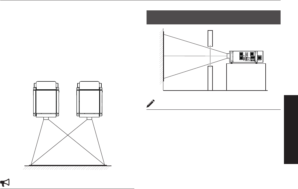
Projecting images by arranging projectors
side by side
The lens shift feature enables you to use up to two
projectors that are arranged side by side.
Arranging two projectors side by side enhances the
brightness level, and helps to project images that are
sufficiently bright even when the venue is relatively big or
bright.
When projecting images by arranging the projectors side
by side, adjust the shift amount of both projectors
accordingly to superimpose the images.
.
CAUTION
0When using the projectors by arranging them side by
side, ensure that the installation site is sufficiently
strong and there is proper air cooling around the
projectors.
For details, please consult your authorized dealer.
When light passes through the glass of
projection booth
.
OPERATE I/B
DVI 3
USB
LAN
RS-232C
STANDBY/ON
LAMP
WARNING
DVI 4
DVI 1
DVI 2
e-shift Sync
RS-232C
1
2
MEMO
0When light passes through the glass, the quantity of
light decreases. Make sure that the glass of the
projection booth is not more than one piece.
0Do not use glass if possible.
0When projecting light on an inclined glass surface,
adjust the glass angle as well as installation angle of
this unit accordingly to prevent impact on the image
due to diffuse reflection.
15
Connection and Installation
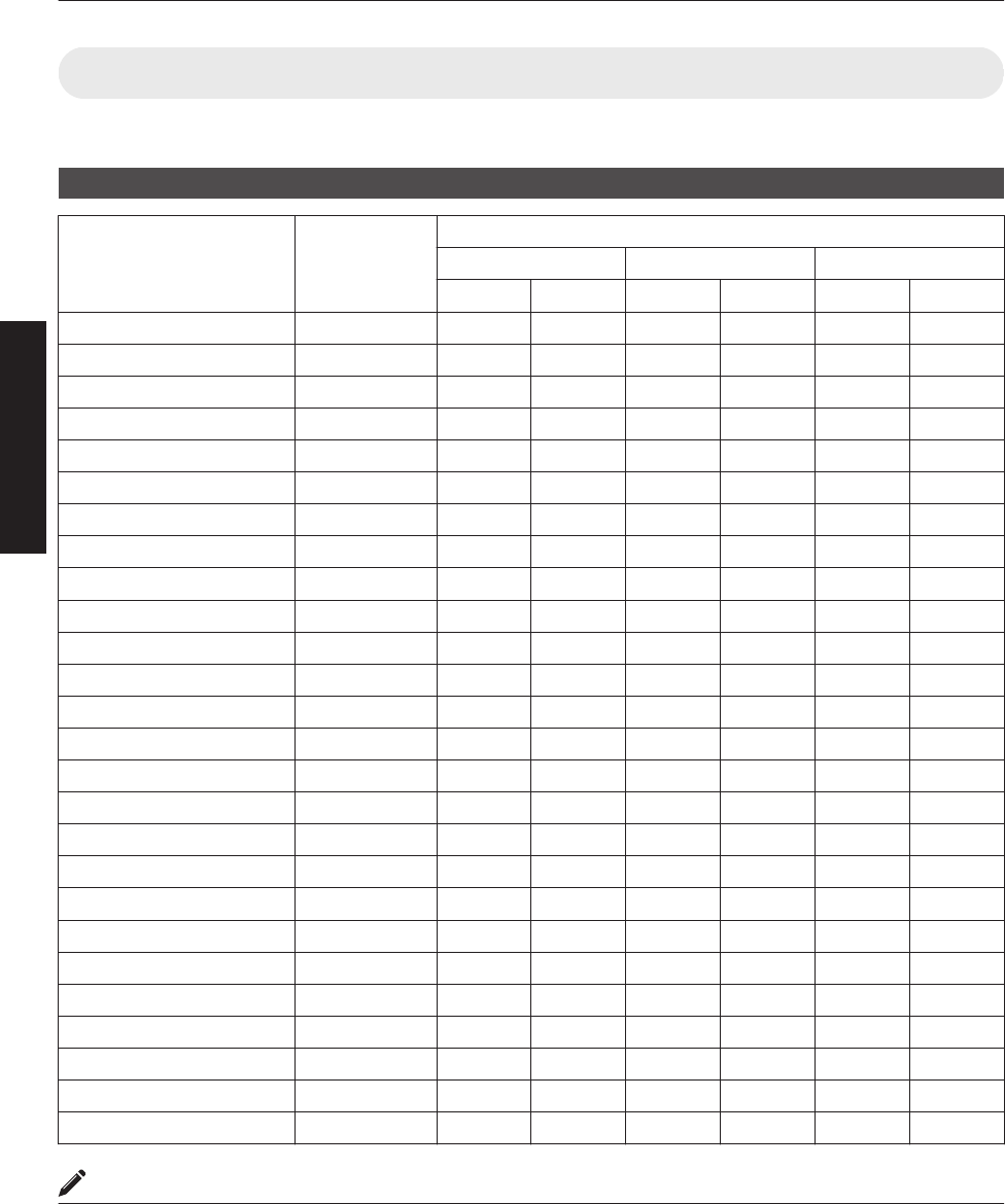
Screen Size and Projection Distance
Adjust the distance from the lens to the screen to achieve your desired screen size.
GL-MS4015SZ / GL-MS4016SZ / GL-MS4021SZ Zoom lens
Projection Screen Size
(Diagonal Length) Image Width
Projection distance
GL-MS4015SZ GL-MS4016SZ GL-MS4021SZ
Tele End Wide End Tele End Wide End Tele End Wide End
50" (Approx. 1.27 m) 1.10 m - - 1.97 m 1.58 m - -
60" (Approx. 1.53 m) 1.31 m - - 2.37 m 1.92 m - -
70" (Approx. 1.79 m) 1.54 m - - 2.78 m 2.25 m - -
80" (Approx. 2.03 m) 1.75 m 3.19 m 2.58 m 3.19 m 2.58 m 6.38 m 3.72 m
90" (Approx. 2.29 m) 1.97 m 3.60 m 2.91 m 3.60 m 2.91 m 7.19 m 4.24 m
100" (Approx. 2.54 m) 2.19 m 4.01 m 3.25 m 4.01 m 3.25 m 8.01 m 4.71 m
110" (Approx. 2.79 m) 2.41 m 4.42 m 3.58 m 4.42 m 3.58 m 8.82 m 5.17 m
120" (Approx. 3.05 m) 2.63 m 4.83 m 3.91 m 4.83 m 3.91 m 9.63 m 5.64 m
130" (Approx. 3.30 m) 2.85 m 5.24 m 4.25 m 5.24 m 4.25 m 10.44 m 6.11 m
140" (Approx. 3.56 m) 3.07 m 5.65 m 4.58 m 5.65 m 4.58 m 11.25 m 6.57 m
150" (Approx. 3.81 m) 3.29 m 6.06 m 4.91 m 6.06 m 4.91 m 12.06 m 7.04 m
160" (Approx. 4.06 m) 3.51 m 6.46 m 5.25 m 6.46 m 5.25 m 12.87 m 7.50 m
170" (Approx. 4.32 m) 3.73 m 6.87 m 5.58 m 6.87 m 5.58 m 13.68 m 7.97 m
180" (Approx. 4.57 m) 3.94 m 7.28 m 5.91 m - 5.91 m 14.49 m 8.44 m
190" (Approx. 4.83 m) 4.16 m 7.69 m 6.24 m - 6.24 m 15.30 m 8.90 m
200" (Approx. 5.08 m) 4.38 m 8.10 m 6.58 m - 6.58 m 16.12 m 9.44 m
210" (Approx. 5.33 m) 4.60 m 8.51 m 6.91 m - 6.91 m 16.93 m 9.83 m
220" (Approx. 5.59 m) 4.82 m 8.92 m 7.24 m - - 17.74 m 10.30 m
230" (Approx. 5.84 m) 5.04 m 9.33 m 7.58 m - - 18.55 m 10.77 m
240" (Approx. 6.10 m) 5.26 m 9.74 m 7.91 m - - 19.36 m 11.23 m
250" (Approx. 6.35 m) 5.48 m 10.15 m 8.24 m - - 20.17 m 11.70 m
260" (Approx. 6.60 m) 5.70 m 10.55 m 8.58 m - - 20.98 m 12.16 m
270" (Approx. 6.86 m) 5.92 m 10.96 m 8.91 m - - 21.79 m 12.63 m
280" (Approx. 7.11 m) 6.14 m 11.37 m 9.24 m - - 22.60 m 13.10 m
290" (Approx. 7.37 m) 6.36 m 11.78 m 9.57 m - - 23.41 m 13.56 m
300" (Approx. 7.62 m) 6.57 m 12.19 m 9.91 m - - 24.23 m 14.03 m
MEMO
0The distance indicated in the table is an estimated value when an image with a resolution of 4096×2400 is projected.
Please use them as reference during installation.
16
Connection and Installation

GL-MS4011S Short focal length lens
Projection Screen Size (Diagonal Length) Image Width Projection distance
50" (Approx. 1.27 m) 1.10 m 1.16 m
60" (Approx. 1.52 m) 1.31 m 1.41 m
70" (Approx. 1.78 m) 1.53 m 1.66 m
80" (Approx. 2.03 m) 1.75 m 1.91 m
90" (Approx. 2.29 m) 1.97 m 2.16 m
100" (Approx. 2.54 m) 2.19 m 2.41 m
110" (Approx. 2.79 m) 2.41 m 2.66 m
120" (Approx. 3.05 m) 2.63 m 2.91m
130" (Approx. 3.30 m) 2.85 m 3.17 m
140" (Approx. 3.56 m) 3.07 m 3.42 m
150" (Approx. 3.81 m) 3.29 m 3.67 m
160" (Approx. 4.06 m) 3.51 m 3.92 m
170" (Approx. 4.32 m) 3.73 m 4.17 m
180" (Approx. 4.57 m) 3.94 m 4.42 m
190" (Approx. 4.83 m) 4.16 m 4.67 m
200" (Approx. 5.08 m) 4.38 m 4.92 m
210" (Approx. 5.33 m) 4.60 m 5.17 m
220" (Approx. 5.59 m) 4.82 m 5.43 m
230" (Approx. 5.84 m) 5.04 m 5.68 m
240" (Approx. 6.10 m) 5.26 m 5.93 m
250" (Approx. 6.35 m) 5.48 m 6.18 m
MEMO
0The distance indicated in the table is an estimated value when an image with a resolution of 4096×2400 is projected.
Please use them as reference during installation.
17
Connection and Installation
Connecting Video Signals of the Computer
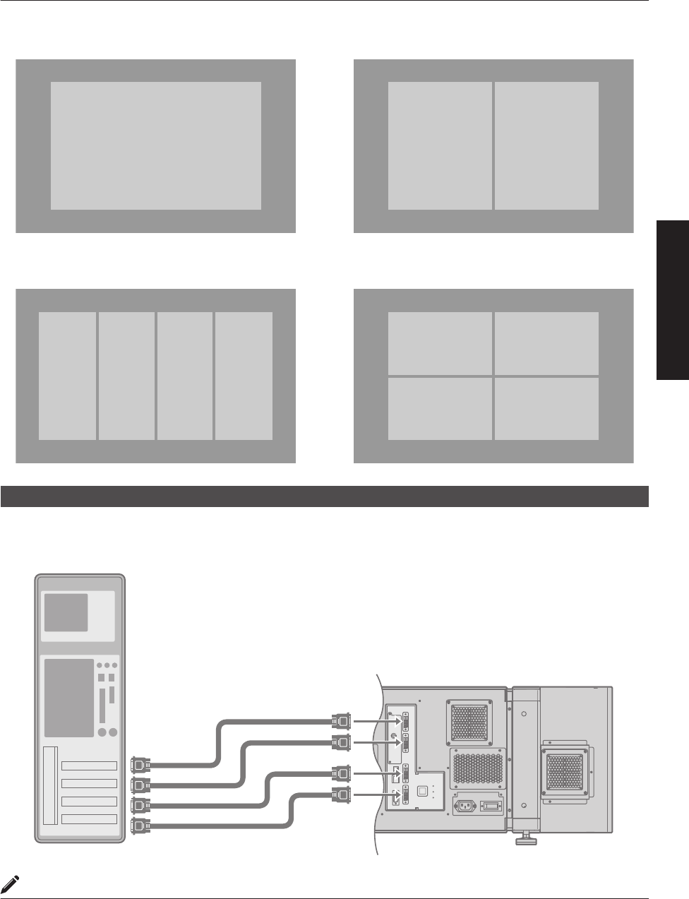
Connection During Single-Screen Mode Display
The single-screen mode displays signals (up to four signals) from a computer as a single video image.
To select to the single-screen mode, set “Display Mode” in the “Setting” menu to “Single”. (P. 38)
Possible Input Signals and Projected Image
Computer Projector
Terminal for
Connection
Output Status Displayed
Projector Image
Resolution Channel Link Status
4096×2400
2ch Dual DVI 1, DVI 3 2 Stripes 2048×2400
4096×2400
* (8192×4800)
4ch Single DVI 1 to DVI 4 Cross 2048×1200
4 Stripes 1024×2400
4096×2160
2ch Dual DVI 1, DVI 3 2 Stripes 2048×2160
4096×2160
* (8192×4320)
4ch Single DVI 1 to DVI 4 Cross 2040×1080
4 Stripes 1024×2160
3840×2400
2ch Dual DVI 1, DVI 3 2 Stripes 1920×2400
3840×2400
* (7680×4800)
4ch Single DVI 1 to DVI 4 Cross 1920×1200
4 Stripes 960×2400
3840×2160
2ch Dual DVI 1, DVI 3 2 Stripes 1920×2160
3840×2160
* (7680×4320)
4ch Single DVI 1 to DVI 4 Cross 1920×1080
4 Stripes 960×2160
2048×1200 1ch Single DVI 1 Normal 2048×1200 4096×2400
2048×1080 1ch Single DVI 1 Normal 2048×1080 4096×2160
1920×1200 1ch Single DVI 1 Normal 1920×1200 3840×2400
1920×1080 1ch Single DVI 1 Normal 1920×1080 3840×2160
1600×1200 1ch Single DVI 1 Normal 1600×1200 3200×2400
1280×1024 1ch Single DVI 1 Normal 1280×1024 2560×2048
1024×768 1ch Single DVI 1 Normal 1024×768 2048×1536
800×600 1ch Single DVI 1 Normal 800×600 1600×1200
640×480 1ch Single DVI 1 Normal 640×480 1280×960
* (DLA-VS4810) An 8K image is displayed when e-shift sync signal is input.
MEMO
0This projector converts the frame rate to 60 Hz regardless of the synchronizing signal frequency at the computer’s
end.
0If the resolution of the PC is 2048×1200 or lower, images are displayed upon doubling the number of the vertical
and horizontal pixels.
18
Connection and Installation
.
DVI 3DVI 1
DVI 1
DVI 4DVI 3DVI 2DVI 1
DVI 1
DVI 4DVI 3
DVI 2
Cross4 Stripes
2 StripesNormal
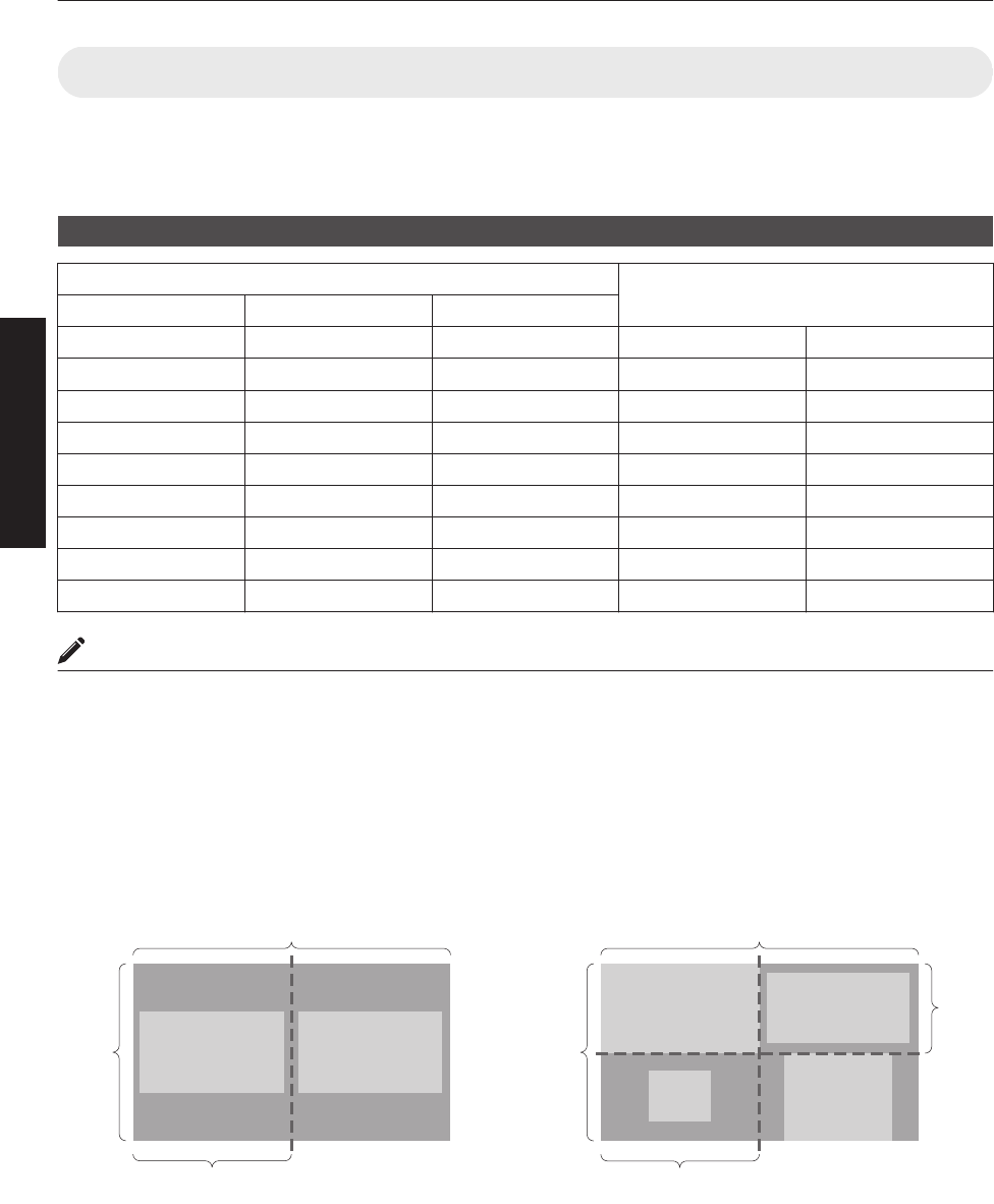
Connection During Single-Screen Mode Display
Below is the connection example for four-channel signals from the computer.
For two-channel signals from the computer, connect to the [DVI 1] and [DVI 3] terminals of this projector.
.
OPERATE I/B
DVI 3
USB
LAN
RS-232C
STANDBY/ON
LAMP
WARNI NG
DVI 4
DVI 1
DVI 2
e-shift Sync
RS-232C
2
DVI-D Cable
(Sold Separately)
To DV I
Terminal
Desktop Computer
MEMO
0Depending on your DVI-D cable, the signal may attenuate and the image become unstable.
0Use of DVI-D cables compliant with the DDWG standard is recommended.
19
Connection and Installation
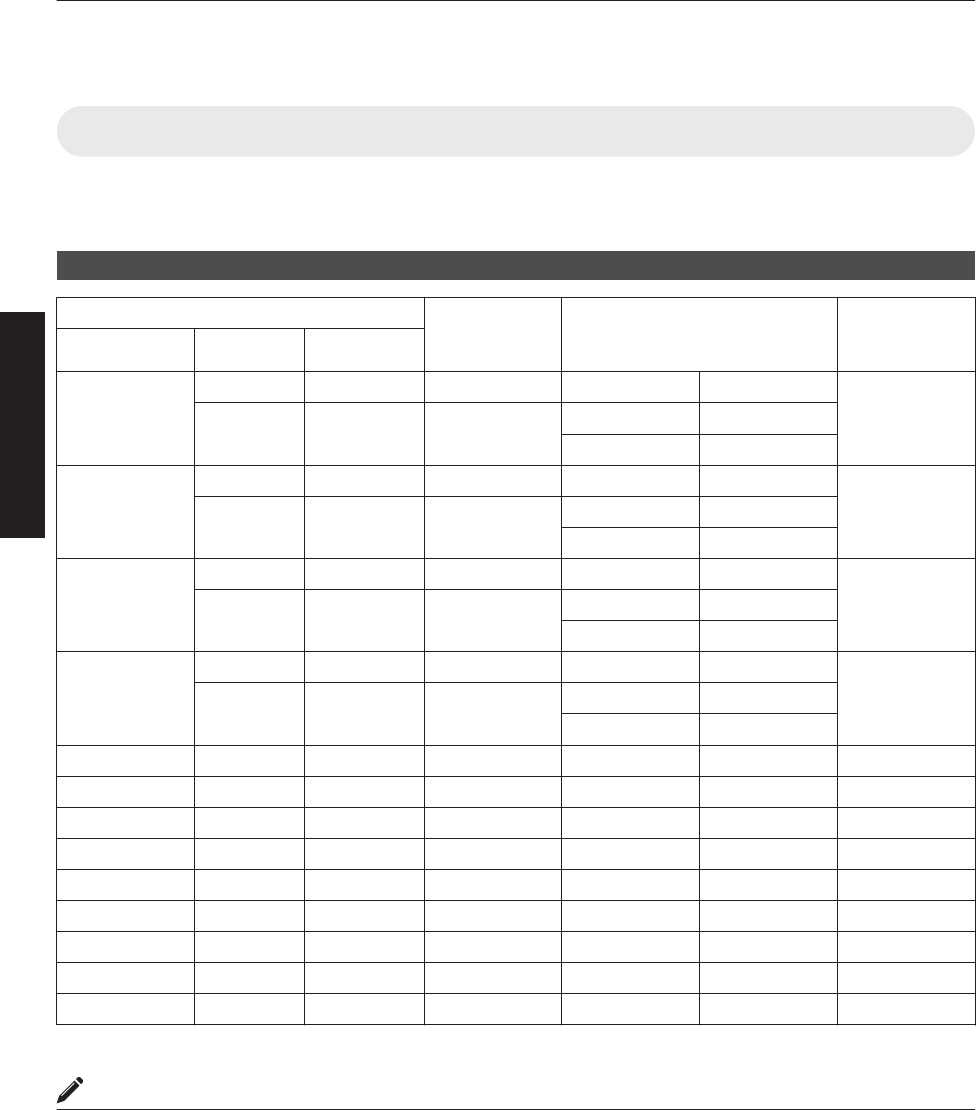
Connection During Two-Screen/Four-Screen Mode Display
The two-screen/four-screen mode enables simultaneous display of signals from two or four computers.
To select the two-screen mode, set “Display Mode” in the “Setting” menu to “Double”. To select the four-screen mode,
set “Display Mode” to “Cross”. (P. 38)
Possible Input Signals and Projected Image
Computer Output Status
Resolution Channel Link Status
2048×1200 1ch Single Normal 2048×1200
2048×1080 1ch Single Normal 2048×1080
1920×1200 1ch Single Normal 1920×1200
1920×1080 1ch Single Normal 1920×1080
1600×1200 1ch Single Normal 1600×1200
1280×1024 1ch Single Normal 1280×1024
1024×768 1ch Single Normal 1024×768
800×600 1ch Single Normal 800×600
640×480 1ch Single Normal 640×480
MEMO
0This projector converts the frame rate to 60 Hz regardless of the synchronizing signal frequency at the computer’s
end.
0The respective signals are displayed at the center of the split screen.
0When in the two-screen mode, the screen appears blue (or black depending on the setting) when there is no input.
Two-Screen Mode Four-Screen Mode
(Example) DVI 1: 1920×1080,
DVI 3: 1920×1080
(Example) DVI 1: 2048×1200, DVI 2: 1920×1080,
DVI 3: 1024×768, DVI 4: 1600×1200
.
4096
DVI 1 DVI 3
2400
2048
.
4096
DVI 1
DVI 3
DVI 2
DVI 4
2400
1200
2048
20
Connection and Installation
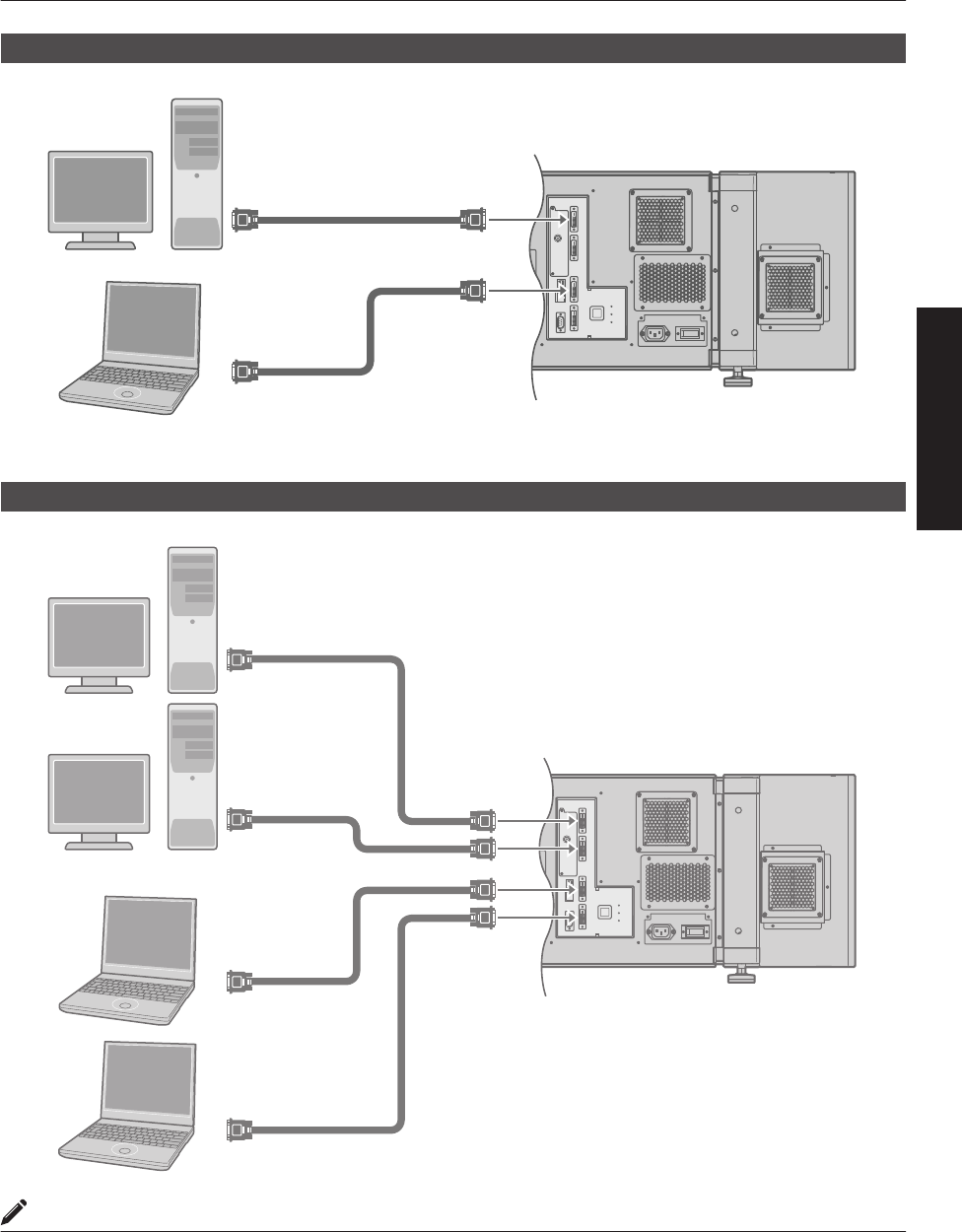
Connection Example During Two-Screen Mode
.
OPERATE I/B
DVI 3
USB
LAN
RS-232C
STANDBY/ON
LAMP
WARNI NG
DVI 4
DVI 1
DVI 2
e-shift Sync
RS-232C
2
Laptop Computer
To DV I
Terminal
DVI-D Cable
(Sold Separately)
To DV I
Terminal
Desktop Computer
Connection Example During Four-Screen Mode
.
OPERATE I/B
DVI 3
USB
LAN
RS-232C
STANDBY/ON
LAMP
WARNING
DVI 4
DVI 1
DVI 2
e-shift Sync
RS-232C
2
Laptop Computer
To DV I
Terminal
To DV I
Terminal
To DV I
Terminal
DVI-D Cable
(Sold Separately)
To DV I
Terminal
Desktop Computer
MEMO
0Depending on your DVI-D cable, the signal may attenuate and the image become unstable.
0Use of DVI-D cables compliant with the DDWG standard is recommended.
21
Connection and Installation
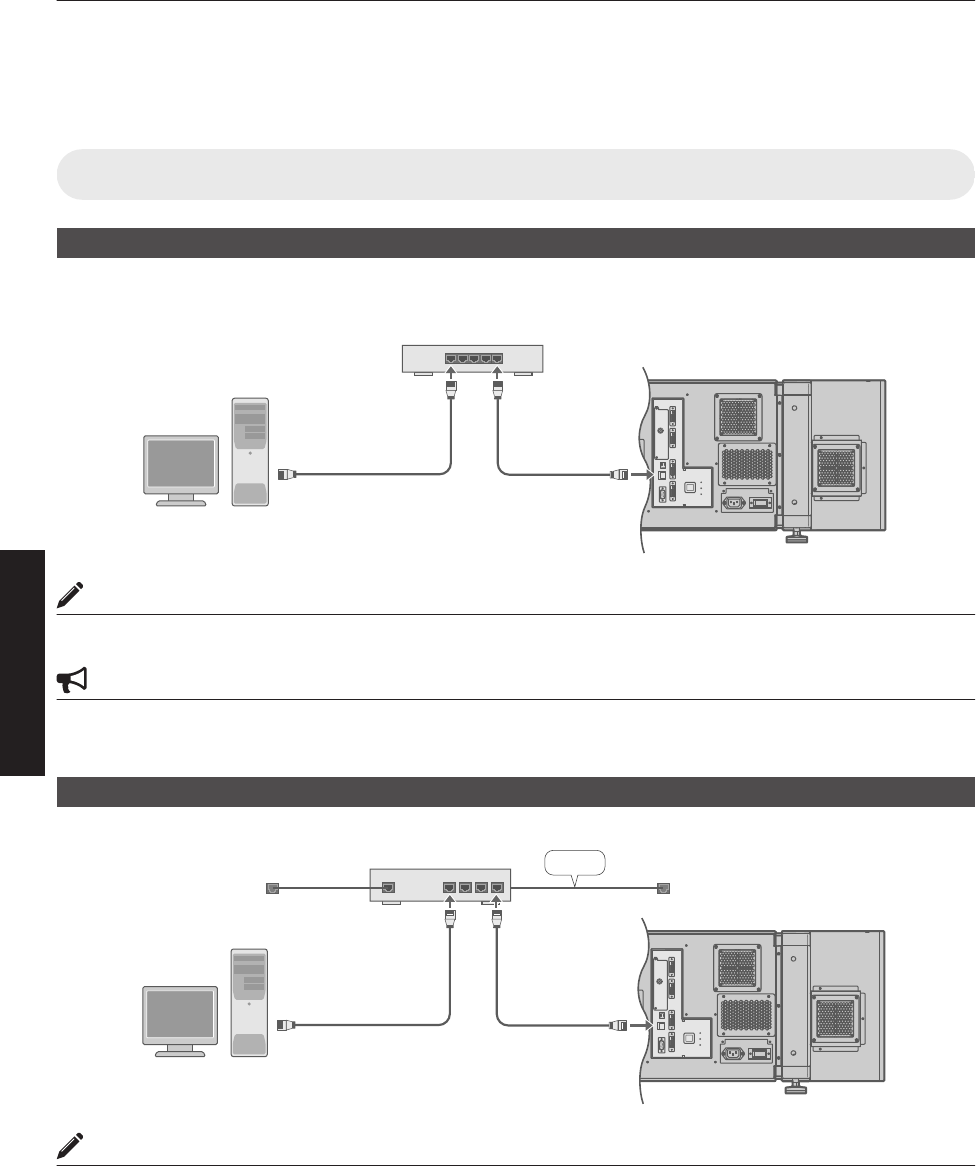
Connection Using a LAN Cable
Connect this projector, the computer for controlling this projector, and the switching hub using LAN cables, followed
by configuring the network.
Connection Example
When assigning a static IP address
You can acquire the IP address from the controlling computer simply by configuring a network that consists of this
projector, the controlling computer, and switching hub. Please refer to technical books on networks for details.
.
OPERATE I/B
DVI 3
USB
LAN
RS-232C
STANDBY/ON
LAMP
WARNIN G
DVI 4
DVI 1
DVI 2
e-shift Sync
RS-232C
2
To LAN TerminalTo Network Terminal
Switching Hub
MEMO
0Make use of Cat. 5 (equivalent or higher) straight 100Base-TX LAN cables.
CAUTION
0When connecting this projector and the controlling computer for this projector using other network, be sure to consult
the network administrator of the network in use or refer to technical books on networks.
When assigning IP address from the DHCP server
.
OPERATE I/B
DVI 3
USB
LAN
RS-232C
STANDBY/ON
LAMP
WARNING
DVI 4
DVI 1
DVI 2
e-shift Sync
RS-232C
2
LAN1
WAN LAN2 LAN3 LAN4
LAN
Router
(DHCP Server)
To LAN TerminalTo Network Terminal
MEMO
0Make use of Cat. 5 (equivalent or higher) 100Base-TX LAN cables.
22
Network Settings
Specifications of PC for Controlling this Projector
OS Windows 7 (32-bit, 64-bit), Windows 8 (32-bit, 64-bit), Windows 10 (32-bit, 64-bit)
Browser Internet Explorer 10, Internet Explorer 11, Google Chrome, Firefox
MEMO
0Windows is either registered trademark or trademark of Microsoft Corporation in the United States and/or other
countries.
CAUTION
0The PC specifications above are reference values for the application software to run smoothly, and are not intended
to guarantee their operation.
Note that the applications may not run smoothly depending on the condition of use of the respective users even
when the system requirements are satisfied.
23
Network Settings
Turning On the Main Power
1Check to ensure that this projector, computer, and switching hub are properly
connected
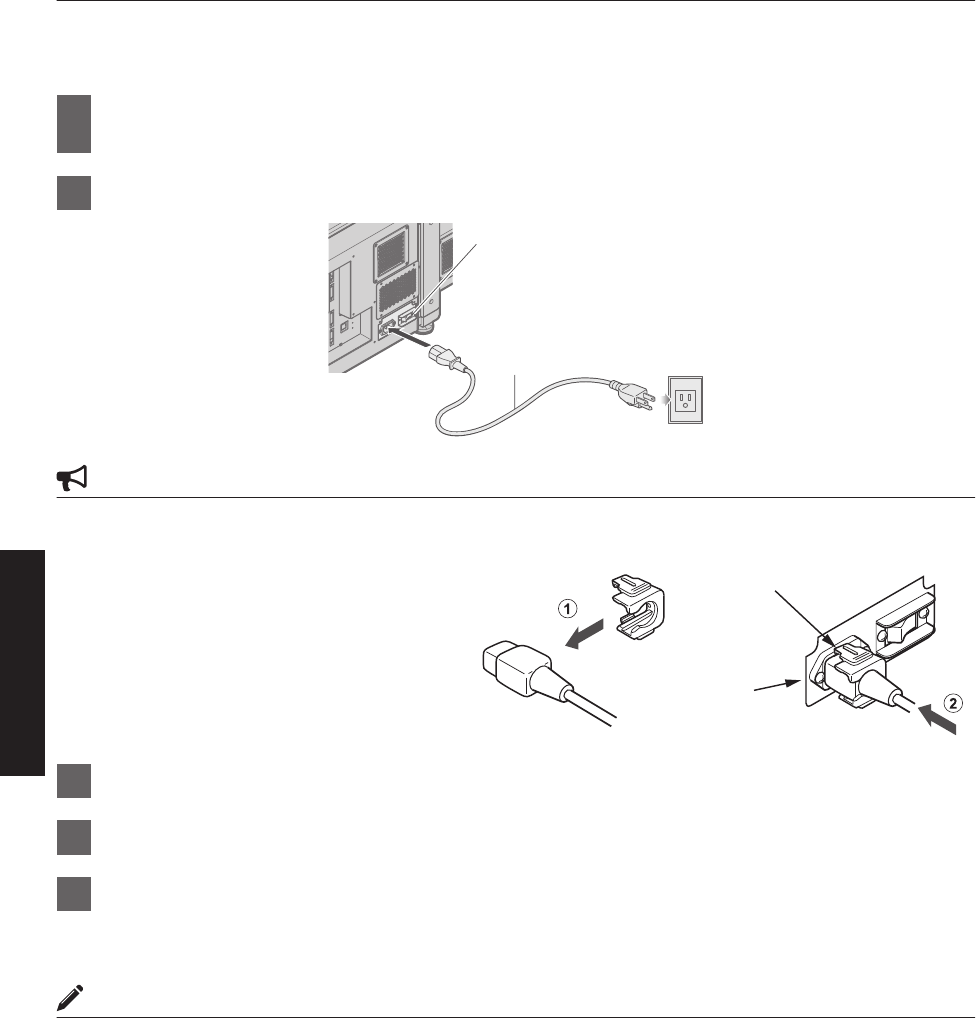
2Connect the power cord to the power input terminal of this projector
.
5
2
3
Power Cord
(Supplied)
CAUTION
0Do not connect the power cord when a lens (optional) is not attached.
You can secure the power cord to this projector.
AAttach the plug holder to the power cord.
BInsert the plug holder into the projector until
the upper and lower securing levers are
locked.
3Insert plug into the power outlet on the wall
4Remove the lens cap
5Turn on the main power of the projector to set to [C]
0The [STANDBY/ON], [LAMP] and [WARNING] indicators light up for about 45 seconds. Thereafter, only the
[STANDBY/ON] indicator lights up in red.
MEMO
0The default IP address of all DLA-VS4010 / DLA-VS4810 is “192.168.0.2”. If multiple units of DLA-VS4010 / DLA-
VS4810 are used on the same network, do not turn on the main power of more than one projector unit at the same
time. Doing so will result in duplication of the IP address, and thereby preventing proper access.
0When using multiple units of DLA-VS4010 / DLA-VS4810, turn on the main power of the second unit and configure
accordingly only after configuration of the first unit is complete. Configure subsequent units using the same
procedure.
0When duplication occurs in the IP address, make sure that only one unit of DLA-VS4010 / DLA-VS4810 is connected
on the same network (turn off the main power of the other DLA-VS4010 / DLA-VS4810 units). Allow a time interval
of at least 10 minutes before accessing. If access fails, turn off the power of all network equipments on the same
network, followed by turning them on again.
AC INLET
Securing Levers
(Upper and lower)
24
Network Settings
IP Address Settings
Set the IP address for this projector. There are 2 methods to set the IP address.
0Assigning a static IP address
0Assigning IP Address from the DHCP Server
Assigning a static IP address
The “IP Address Setting” of this projector is set to “STATIC IP” (the DHCP client function is OFF) by default.
Upon turning on the power, this projector starts running with the following IP address.
IP Address : 192.168.0.2
Subnet Mask : 255.255.255.0
Default Gateway : 192.168.0.254
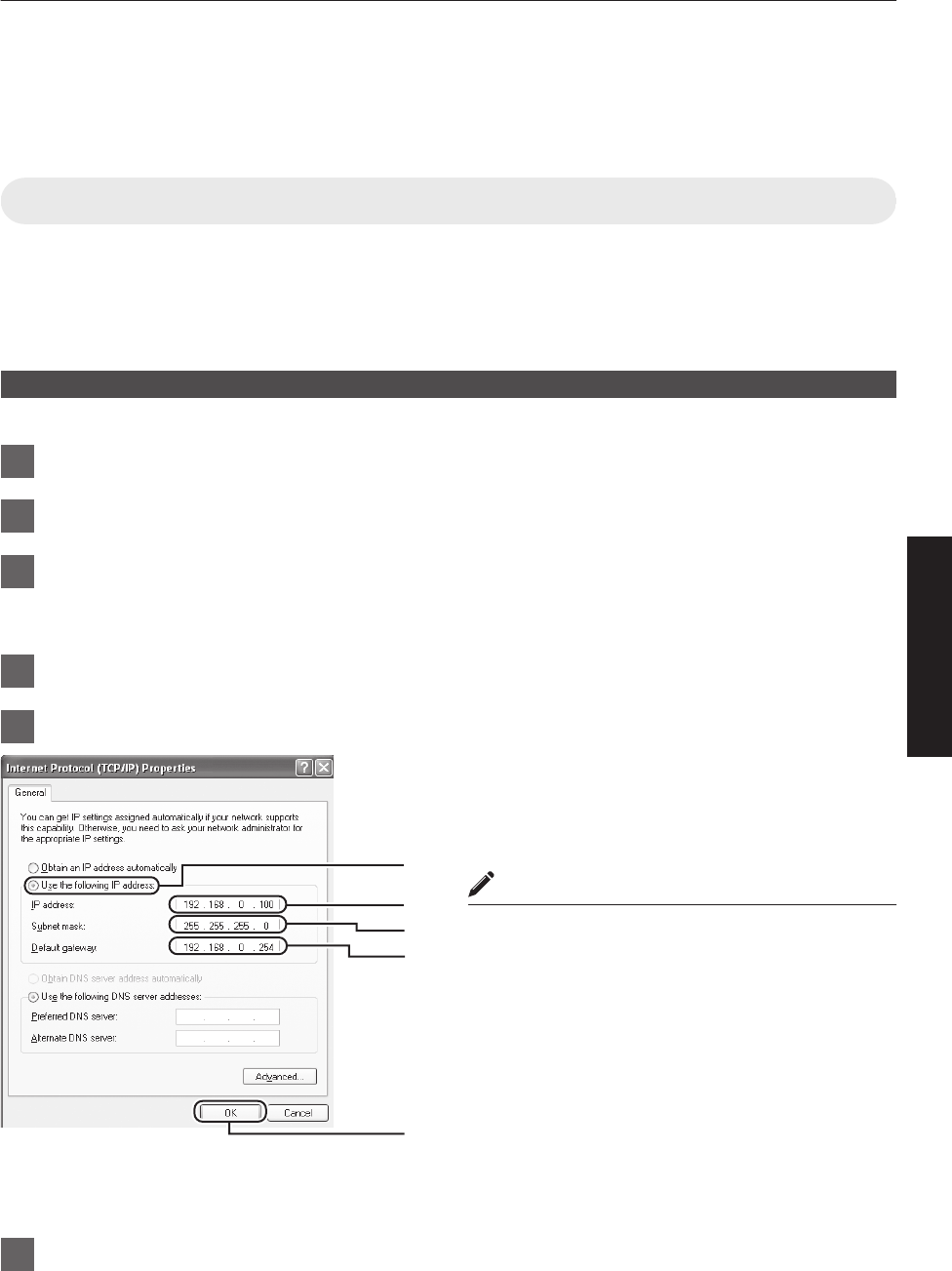
IP address setting at the computer
Set the computer to an IP address that enables communication with this projector.
1Click “Start” and select “Control Panel”
2Double click “Network Connections”
3Right-click on “Local Area” and select “Properties”
0Check to ensure that the “Client for Microsoft Networks” and “Internet Protocol(TCP/IP)” check boxes are
selected.
4Select “Internet Protocol(TCP/IP)” and click “Properties”
5Set the IP address
ASelect “Use the following IP address”
BSet “IP address”
(For example, use 192.168.0.100 when DLA-VS4010 /
DLA-VS4810 is in its default settings)
MEMO
0Make sure that you take note of the original IP
address before altering.
0When setting, ensure that a duplicate IP address is
not used within the same network environment.
CSet “Subnet mask”
Set to a value that is appropriate for the setting operation.
Clarify with the network administrator if you have any
queries.
(Use 255.255.255.0 when the camera is in its default
settings)
DWhen a “Default gateway” is present, make use of the IP
address (e.g., 192.168.0.254)
EClick “OK”
6Click “OK” on the “Local Area Connection Properties” screen
A
B
C
D
E
25
Network Settings
Setting (Changing) the IP address of this projector
When using Internet Explorer
1Launch the Internet Explorer on the
computer
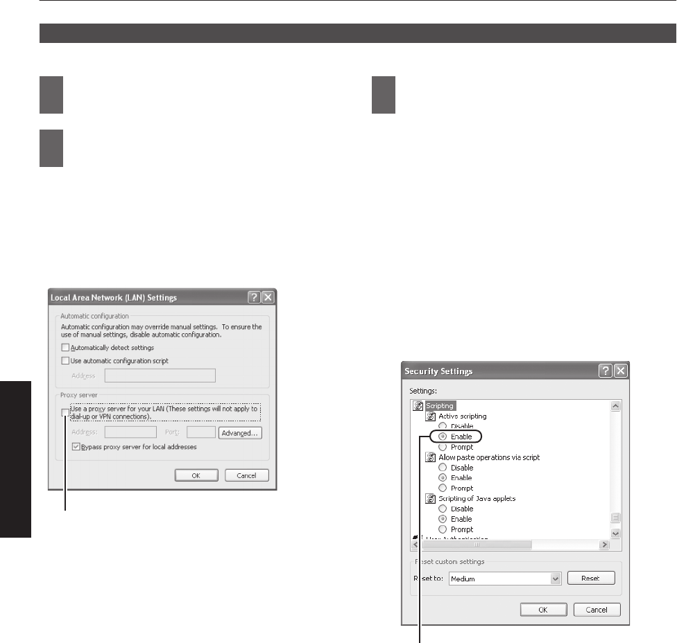
2Check if the proxy has been set in the
“LAN Setting” of the Internet Explorer
AClick “Tools” and select “Internet Options”
BClick “Connections” and click “LAN Setting”
CCheck if the check for “Use a proxy server for your
LAN” has been selected
0If the check mark has been selected,
deselect it.
.
Deselct the check
3Check if the “Active scripting” of the
Internet Explorer is disabled
AClick “Tools” and select “Internet Options”
BClick in the order of “Security” " “Trusted Sites”
" “Sites”
CDeselect the check “Required server verification
(https:) for all sites in this zone”
DEnter “http://192.168.0.2” under “Add this web
site to the zone” and click “Add”
EClick “OK”
FSelect “Trusted Sites” and click “Custom Level”
GCheck if the check for “Active scripting” under
“Scripting” has been selected
0If the check mark has been deselected,
select it.
.
Select “Enable”
26
Network Settings
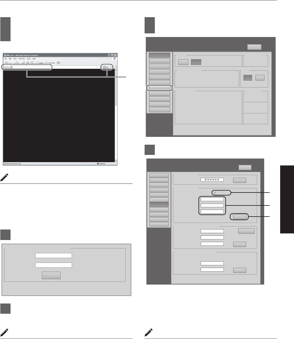
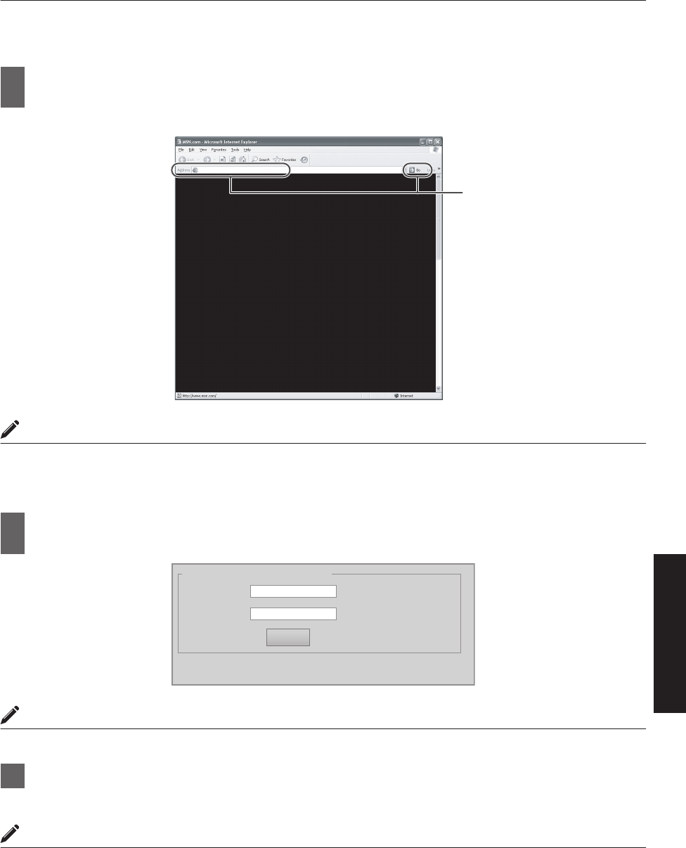
4
Enter “http://192.168.0.2” in the
address field of the Internet Explorer,
and click “Go”
0A login screen for this projector appears.
.
http://192.168.0.2
4
MEMO
0When “LAN Setting” in Internet Explorer is set to “Use
a proxy server for your LAN” it may not be possible to
designate addresses directly. Change the proxy
settings.
0If a “Security Warning” screen appears, click “OK” and
continue.
5Enter “advanced” in “Login Name”
.
Input Your Login Name & Password
Login Name advanced
Password
LOGIN
6Click “LOGIN”
0The “Main” menu for this projector appears.
MEMO
0You can alter the user name and password in the
“Admin.Network” menu. Specify a user name and
password of not more than eight single-byte
alphanumeric characters. (P. 43)
0If you have forgotten the password, please consult
your authorized dealer.
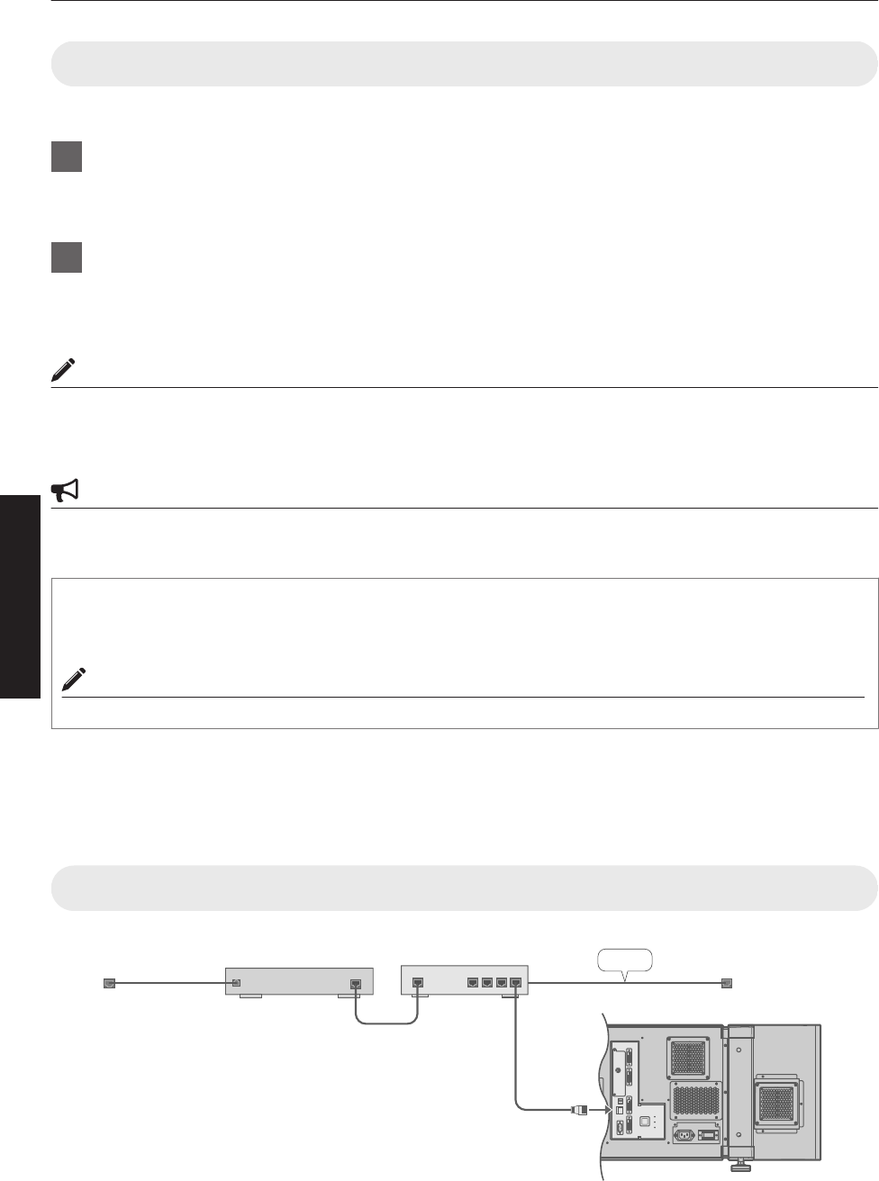
7Click “Admin.Network” in the “Main”
menu
.
Main
DVI Rate(Hz) Pixel H Pixel V Link
1 60.00 2048 2400 Dual
2
3 60.00 2048 2400 Dual
4
Image
Setting
Convergence
Lens
Option
Admin.Network
Admin.E-Mail
Admin.Option
Admin.Signal
License
Logout
host PJ-1
user: advanced
Power
Signal Status
Warning Status
Temperature
10h59m
Light Source Time Hide
Exhaust
30.3 deg.C
Intake
30.3 deg.C
Inside
30.3 deg.C
ON OFF
ONOFF
PROJECTION None
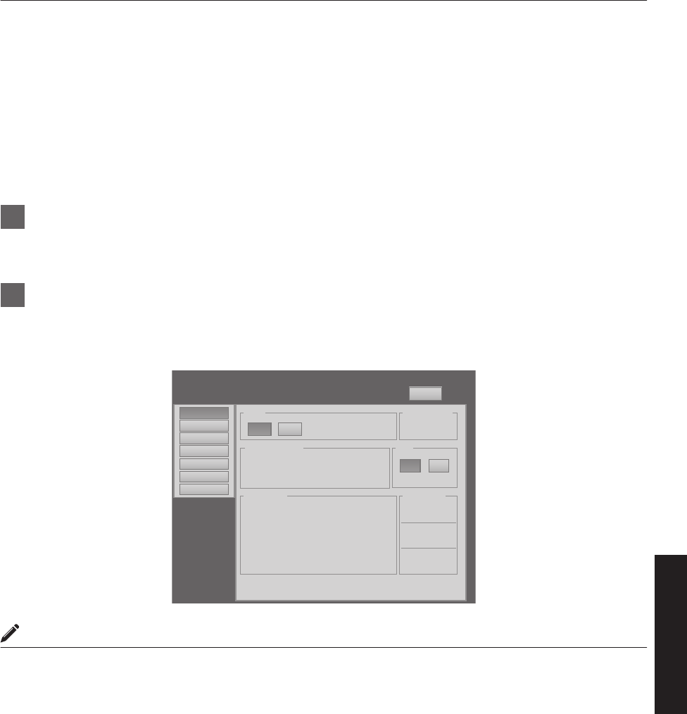
8Set the IP address for this projector
.
Main
Image
Setting
Convergence
Lens
Option
Admin.Option
Admin.Signal
Admin.Network
Admin.Mail
Logout
host PJ-1
user: advanced
Host Name Setting
SET
Host Name
PJ
IP Address Setting
SET
DHCP Client DHCP
IP Address 192.168.1.100
User Login Name/Password Change
SET
Initialize
User Name root
New Password
Confirm
New Password
Admin. Login Password Change
SET
User Name advanced
New Password
Confirm
New Password
Subnet Mask 255.255.255.0
Default Gateway 192.168.1.1
Mac Address 01:23:45:67:89:AB
STATIC IP
License
A
B
C
ASelect “STATIC IP” in “DHCP Client”
BEnter the values for “IP Address”, “Subnet Mask”
and “Default Gateway”
CClick “SET”
MEMO
0Access from computers may not be successful as this
projector’s IP address has been changed. Set and
change the computer’s IP address when accessing
this projector.
27
Network Settings
Assigning IP Address from the DHCP Server
The IP address is automatically assigned by the DHCP server.
1After connecting, turn on the main power
0Refer to P. 22 on the details of connection.
0Refer to P. 24 on procedures to turn on the main power.
2Set the “DHCP Client” setting of this projector to “DHCP”
0The “DHCP Client” of this projector is set to “STATIC IP” (the DHCP client function is OFF) by default. When
assigning an IP address from the DHCP server, access this projector from the computer to alter the settings.
For details on the setting procedures, refer to “Setting (Changing) the IP address of this projector”P. 26.
MEMO
0Please consult the network administrator on the IP address assigned to this projector.
0When “DHCP Client” is set to “DHCP”, and if the projector is started up in a LAN where a DHCP server does not
exist, the projector will start up using the default IP address instead.
CAUTION
0Configure the DHCP server such that the same IP address is assigned to the “Mac Address” of this projector by the
DHCP server at all times. Connection may fail if the above setting is not performed.
Connecting this projector and the computer using a USB cable
You can connect this projector and the controlling computer using a USB cable.
0You need to install a driver in order to connect the projector and computer using a USB cable.
MEMO
0For details on the installation of the USB driver, please consult your authorized dealer.
Using the Mail Delivery Feature
This feature enables delivery of mail (error message) to the preset e-mail address when error occurs inside this projector
unit.
Connection Example (When DHCP Server is Used)
.
OPERATE I/B
DVI 3
USB
LAN
RS-232C
STANDBY/ON
LAMP
WARNIN G
DVI 4
DVI 1
DVI 2
e-shift Sync
RS-232C
2
LAN1
WAN LAN2 LAN3 LAN4
ETHER
To LAN
Terminal
LAN
DHCP Server
ADSL modem, etc.
To Internet
Connection
28
Network Settings
Projecting Image
If setting for this projector is not completed, refer to “User Settings Menu”P. 34 upon turning on the power and configure
the settings accordingly.
Once the basic settings are configured, this projector can be used by simply performing the following operation
procedures.
0Remove the lens cap.
0Connect this projector to the computer. (P. 19, 21)
0Connect the LAN cable. (P. 22)
1Set this projector to the standby mode, and display the “Main” menu
0Refer to “Turning On the Main Power”P. 24, and steps 4 to 6 of “Assigning a static IP address”P. 25.
0The [STANDBY/ON] indicator lights up in red.
2Click the “ON” button under the “Power” item of the “Main” menu to project the image
0The power of this projector turns on, and formatting is done taking a few minutes. A gray image will be displayed
during formatting. The projected image appears once formatting ends.
0The [STANDBY/ON] indicator lights up in green.
.
DVI Rate(Hz) Pixel H Pixel V Link
1 60.00 2048 2400 Dual
2
3 60.00 2048 2400 Dual
4
Power
Signal Status
Warning Status
Temperature
10h59m
Light Source Time Hide
Exhaust
30.3 deg.C
Intake
30.3 deg.C
Inside
30.3 deg.C
ON OFF
ONOFF
PROJECTION None
Main
Image
Setting
Convergence
Lens
Option
License
Logout
host PJ-1
user: root
MEMO
0You can also turn on the power by pressing the [OPERATE Z] button on the projector unit for more than one second.
0The image may flicker for a few seconds immediately after projection starts. This is not a malfunction.
0After the LD block lights up, it takes more than 1 minute for the brightness of the video image on the screen to
stabilize.
29
Operation and Settings
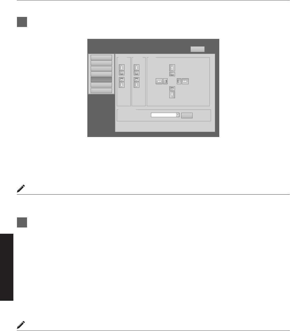
3Adjust the zoom ratio (screen size) (when zoom lens is in use)
You can adjust the focus using the “Zoom” item of the “Lens” menu.
.
Zoom
Setting
Convergence
Lens
Option
Logout
host PJ-1
user: root
Main
Image w
T
Focus
+
_
Shift
LR
U
D
Test Pattern
SET
OFF OFF
License
To enlarge the screen size:
Press the “W” (Wide) end of “Zoom”
To reduce the screen size:
Press the “T” (Tele) end of “Zoom”
MEMO
0The screen size changes each time you click on the inner buttons (a / b). (Fine control)
The outer buttons (d / c) change the screen size when they are depressed. (Coarse control)
4Adjust the position of the projection screen
You can adjust the focus using the “Shift” item of the “Lens” menu.
To shift the image upward:
Press the “U” end of “Shift”
To shift the image downward:
Press the “D” end of “Shift”
To shift the image rightward:
Press the “R” end of “Shift”
To shift the image leftward:
Press the “L” end of “Shift”
MEMO
0When a zoom lens is used, the adjustment range for lens shift is between 0 % to ±50 % in the vertical direction, and
between 0 % to ±25 % in the horizontal direction (during single-screen display).
0When a short focal length lens is used, the adjustment range for lens shift is between 0 % to ±15 % in the vertical
direction, and between 0 % to ±5 % in the horizontal direction (during single-screen display). (P. 14)
0The position changes each time you click on the inner buttons (a / b). (Fine control)
0The image shifts when the outer buttons (d / c) are depressed. (Coarse control)
0The lens shift feature does not function if the lens mechanism is secured (“Lens Fixation Mechanism”P. 14)
30
Operation and Settings
5Adjust the focus
You can adjust the focus using the “Focus” item of the “Lens” menu.
To move the focus point closer:
Press the “+” (Near) end of “Focus”
To move the focus point away:
Press the “-” (Far) end of “Focus”
MEMO
0The focus changes each time you click on the inner buttons (a / b). (Fine control)
The outer buttons (d / c) change the focus when they are depressed. (Coarse control)
6Select a screen mode for projection
You can specify the screen mode using “Display Mode” of the “Setting” menu. (P. 38)
.
Setting
Convergence
Lens
Option
Logout
host PJ-1
user: root
Input Level
Main
Image 0-255(PC)
Display Mode
16-235
11
3
312
4
License
MEMO
0The projected image varies according to the mode of connection. (P. 19, 21)
7Click the “OFF” button under the “Power” item of the “Main” menu to end the projection
0The projector switches to the cool down mode, and the [STANDBY/ON] indicator appears blinking in red.
0A gray image will be displayed for a maximum duration of 2 minutes during the ending process only after several
hours of image projection. Thereafter, the LD block starts to cool down.
0After exiting the cool down mode, the projector switches automatically to the standby mode, and the
[STANDBY/ON] indicator lights up in red.
0You can also turn off the power by pressing the [OPERATE Z] button on the projector unit for more than one
second.
Cool down mode
Cool down mode is a function that cools down the LD block for about 10 seconds after projection ends (ending
process).
0When the projector is in the cool down mode, the [STANDBY/ON] indicator appears blinking in red.
0Do not shut down the main power supply or unplug the power cord when in the cool down mode. Also, do
not block the air inlets and vent holes. Doing so may shorten the lamp life and cause a malfunction.
31
Operation and Settings
8Turn the main power at the rear of the projector unit to off [X]
0The [STANDBY/ON] indicator on the projector unit goes off.
CAUTION
0Do not turn off the main power supply switch when in the cool down mode. Doing so may shorten the lamp life and
cause a malfunction.
0Upon using, attach the lens cap to prevent soiling of the lens.
0When the projector is not to be used for a long time, disconnect the power plug.
Useful Features During Projection
Hiding the projected image temporarily
The projected image can be hidden by clicking the “ON” button under the “Hide” item of the “Main” menu or “Image”
menu.
0When the image is not displayed, pressing “OFF” under the “Hide” item to display the hidden image.
.
Brightness
Setting
Convergence
Lens
Option
Logout
host PJ-1
user: root
Red 0
-30 +30
Green 0
-30 +30
Blue 0
-30 +30
Contrast
Gamma Hide
Red 0
-30 +30
Green 0
-30 +30
Blue 0
-30 +30
Main
Image
ONOFFB CA
License
MEMO
When the image is hidden, the [STANDBY/ON] indicator appears blinking in green.
32
Operation and Settings
Displaying the Menu
1Enter the IP address assigned in the address field of the Internet Explorer, and click
“Go” (P. 27)
0Example: When IP address assigned is “192.168.0.2”, enter “http://192.168.0.2”.
.
http://192.168.0.2
1
MEMO
0When “LAN Setting” in Internet Explorer is set to “Use a proxy server for your LAN” it may not be possible to designate
addresses directly. Change the proxy settings.
0If a “Security Warning” screen appears, click “OK” and continue.
2Enter the login name and the password in the “Login Name” and “Password” fields
respectively
.
Input Your Login Name & Password
Login Name
Password
LOGIN
MEMO
0If you have forgotten the password, please consult your authorized dealer.
3Click “LOGIN”
0The “Main” menu for this projector appears.
MEMO
0You can alter the user name and password in the “Admin.Network” menu. Specify a user name and password of
not more than eight single-byte alphanumeric characters. (P. 43)
33
Operation and Settings

User Settings Menu
After installation and connection are complete, perform the necessary adjustment and setting.
Operate the menus using the computer’s browser to make adjustments and configure settings.
User Settings Menu Structure
Page Menu Name Page Display Item Simplified Description of Item
(1) Main Power
Warning Status
Light Source Time
Signal Status
Temperature
Hide
Power ON/OFF operation
Error code display
LD block information display
Input signal information display
Projector’s interior temperature display
Mute operation
(2) Image Brightness
Contrast
Gamma
Hide
Brightness adjustment
Contrast adjustment
Gamma setting
Mute operation
(3) Setting Input Level
Display Mode
Input level setting
Display method setting
(4) Convergence Red
Blue
Test Pattern
Pixel position adjustment
Pixel position adjustment
Test pattern setting
(5) Lens Zoom
Focus
Shift
Test Pattern
Zoom adjustment
Focus adjustment
Image position adjustment
Test pattern setting
(6) Option Flip
Light Source Power
Back Color
Message Display
Test Pattern
Image inversion setting
LD block power setting
Background color setting
Message display setting
Test pattern setting
34
Operation and Settings
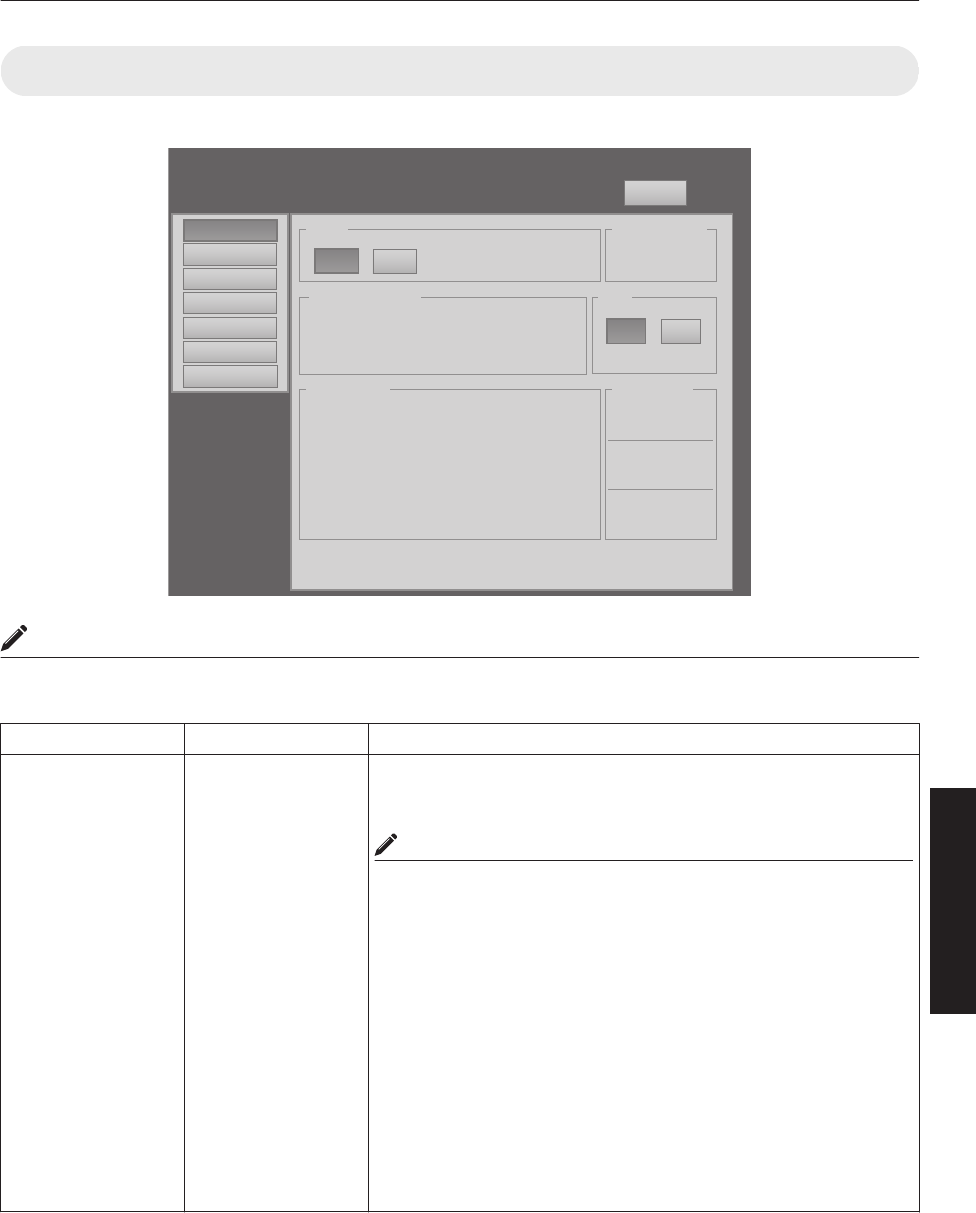
(1) Main Menu
This menu displays the ON/OFF status of the power supply and information on signals input to the projector.
.
DVI Rate(Hz) Pi xel H Pixel V Link
1 60.00 2048 2400 Dual
2
3 60.00 2048 2400 Dual
4
Power
Signal Status
Warning Status
Temperature
10h59m
Light Source Time Hide
Exhaust
30.3 deg.C
Intake
30.3 deg.C
Inside
30.3 deg.C
ON OFF
ONOFF
PROJECTION None
Main
Image
Setting
Convergence
Lens
Option
Logout
host PJ-1
user: root
License
MEMO
0When the power of this unit is off (main power is on), the “Main”, “Image”, “Setting”, “Convergence”, “Lens” and
“Option” menus will be grayed out and will not be selectable.
Item Setting Value Description
Power ON
OFF
Turns on/off the LD block.
ON : Turns on the LD block.
OFF : Turns off the LD block.
MEMO
0The following operating modes of the projector are displayed to the
right of the “OFF” button.
STANDBY : Standby (OFF)
PROJECTION : LD block illuminated (ON)
FAN ENABLE : FAN Enable (OFF " ON)
DEVICE ENABLE : Elemental Device Enable (OFF " ON)
COOLING : Cooling (OFF)
EMERGENCY : Error Occurred (Cooling not performed)
EMERGENCY COOLING : Error Occurred (Cooling performed)
0When in the standby mode, clicking the “ON” button each time
switches the mode in the sequence of “STANDBY” " “DEVICE
ENABLE” " “FAN ENABLE” " “PROJECTION”.
0Clicking the “OFF” button when the power is on switches the
projector to the cooling mode. The power of the projector cannot
be turned on during the cooling process (10 seconds).
35
Operation and Settings
R indicates the factory default.
Item Setting Value Description
Warning Status - Displays the latest error number.
MEMO
0For details on the error code and description, please refer to
“Warning Status”P. 54.
0“None” is displayed when no error is detected.
Light Source Time - Displays the lifetime of the LD block.
Signal Status
DVI
Rate(Hz)
Pixel H
Pixel V
Link
-
-
-
-
-
Displays information on the input signals.
DVI : Displays the DVI input terminal number.
Rate(Hz) : Displays the vertical frequency.
Pixel H : Displays the horizontal resolution.
Pixel V : Displays the vertical resolution.
Link : Displays the link status of the DVI terminal.
MEMO
0This item is not displayed when there is no signal input.
0The text color of “Rate(Hz)” (vertical frequency) turns red in the
case of interlaced signal. And the text turns white in the case of
progressive signal.
Temperature
Exhaust
Intake
Inside
-
-
-
Displays the interior temperature of the projector.
Exhaust : Temperature at the vent holes
Intake : Temperature at the air inlets
Inside : Internal temperature
MEMO
0The color of the text turns red if the temperature becomes
abnormal.
0The text appears white at normal temperature.
Hide R OFF
ON
Enables temporary hiding of the image.
OFF : Do not hide image.
ON : Hide image.
MEMO
0When the image is hidden, the [STANDBY/ON] indicator appears
blinking in green.
36
Operation and Settings
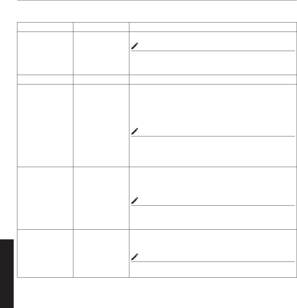
(2) Image Menu
This menu is used for adjusting the image quality.
.
Brightness
Setting
Convergence
Lens
Option
Logout
host PJ-1
user: root
Red 0
-30 +30
Green 0
-30 +30
Blue 0
-30 +30
Contrast
Gamma Hide
Red 0
-30 +30
Green 0
-30 +30
Blue 0
-30 +30
Main
Image
ONOFFB CA
License
R indicates the factory default.
Item Setting Value Description
Brightness
Red
Green
Blue
-30 to +30
(Default Value: 0)
-30 to +30
(Default Value: 0)
-30 to +30
(Default Value: 0)
For adjusting the brightness of the red, green, and blue colors.
Contrast
Red
Green
Blue
-30 to +30
(Default Value: 0)
-30 to +30
(Default Value: 0)
-30 to +30
(Default Value: 0)
For adjusting the contrast of the red, green, and blue colors.
Gamma R A
B
C
For specifying the tone characteristics of the image.
A: Sets gamma to “2.2”.
B : Sets gamma to “1.8”.
C : Sets gamma to “2.6”.
Hide R OFF
ON
Enables temporary hiding of the image.
OFF : Do not hide image.
ON : Hide image.
MEMO
0When the image is hidden, the [STANDBY/ON] indicator appears
blinking in green.
37
Operation and Settings
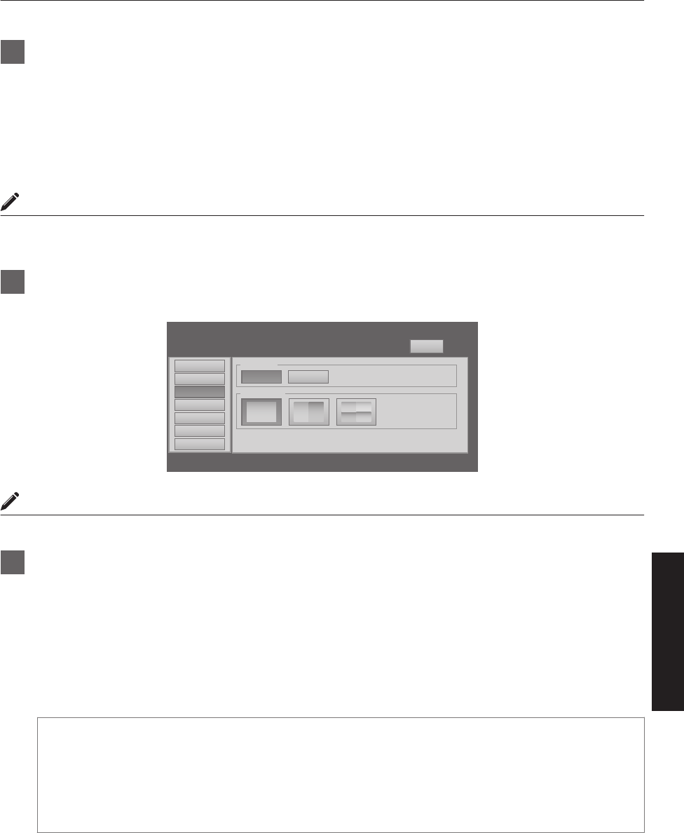
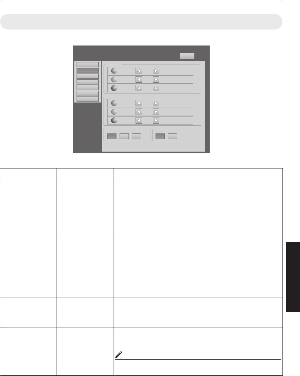
(3) Setting Menu
This menu is used for specifying the input level of the terminal and the display mode.
.
Setting
Convergence
Lens
Option
Logout
host PJ-1
user: root
Input Level
Main
Image 0-255(PC)
Display Mode
16-235
11
3
312
4
License
Single Double Cross
R indicates the factory default.
Item Setting Value Description
Input Level R 0-255(PC)
16-235
For specifying the input level of the video signals.
0-255(PC) : Set to this value under normal circumstances. (Signal
level 0 to 255)
16-235 : For specifying when the signal level is between 16 and
235.
Display Mode R Single
Double
Cross
For specifying the display mode of the projection screen.
Single : Displays input signals on a single screen.
Double : Displays two different input signals on two screens.
The left screen displays images of the [DVI 1] terminal,
and the right screen displays images of the [DVI 3]
terminal.
Cross : Displays four different input signals on four screens.
The top left screen displays images of the [DVI 1]
terminal, the top right screen displays images of the [DVI
2] terminal, the bottom left screen displays images of the
[DVI 3] terminal, while the bottom right screen displays
images of the [DVI 4] terminal.
MEMO
0Please refer to “Connecting Video Signals of the Computer” for
details. (P. 18 to 21)
38
Operation and Settings
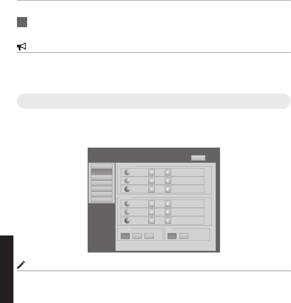
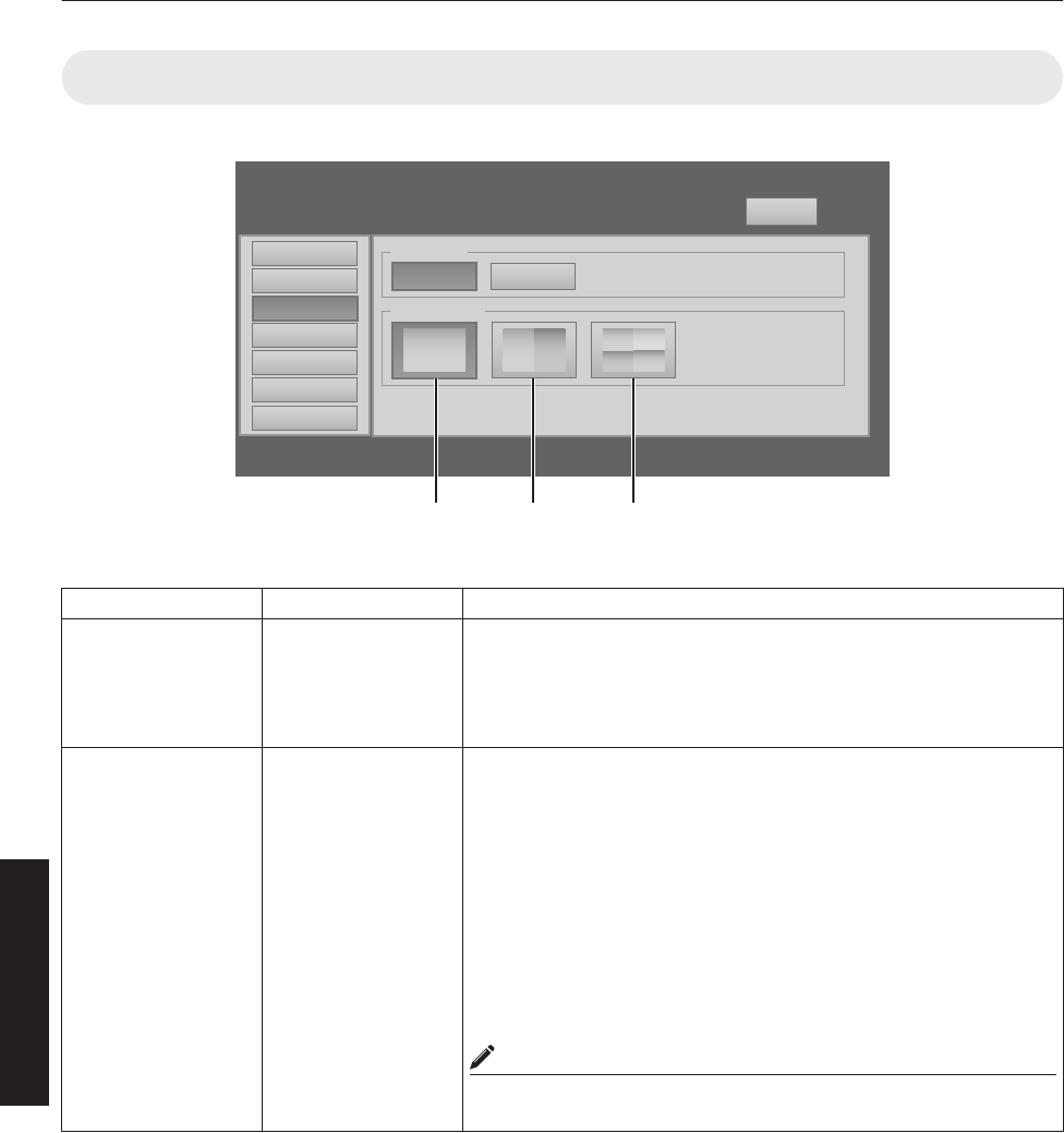
(4) Convergence Menu
This menu is used for correcting color shifts in the optical system.
.
Red
Setting
Convergence
Lens
Option
Logout
host PJ-1
user: root
LR
U
D
Main
Image
Blue
LR
U
D
Test Pattern
SET
OFF OFF
License
R indicates the factory default.
Item Setting Value Description
Red - For adjusting the horizontal/vertical position of red and blue colors on
the image.
MEMO
0The green color value is fixed.
0The outer buttons are used for adjustment in units of 1/4 pixels, and
the inner buttons in units of 1/10 pixels.
0When the image is flipped horizontally or vertically, the horizontal
and vertical directions are reversed.
0Use images with a clear outline (such as Color Cross Hatch
patterns available in this projector) for adjustment.
CAUTION
0When the movement exceeds the limit, the color of the button turns
red.
Blue -
Test Pattern R OFF
Color Bars
Color Cross Hatch
Cross Hatch
Staircase
Ramp
Flat
For projecting the test pattern.
OFF : Do not display the test pattern.
Color Bars : Displays the color bar.
Color Cross Hatch : Displays the color cross hatch pattern.
Cross Hatch : Displays the cross hatch pattern.
Staircase : Displays the staircase (white color).
Ramp : Displays the ramp pattern (white color).
Flat : Displays the flat pattern (white color).
39
Operation and Settings
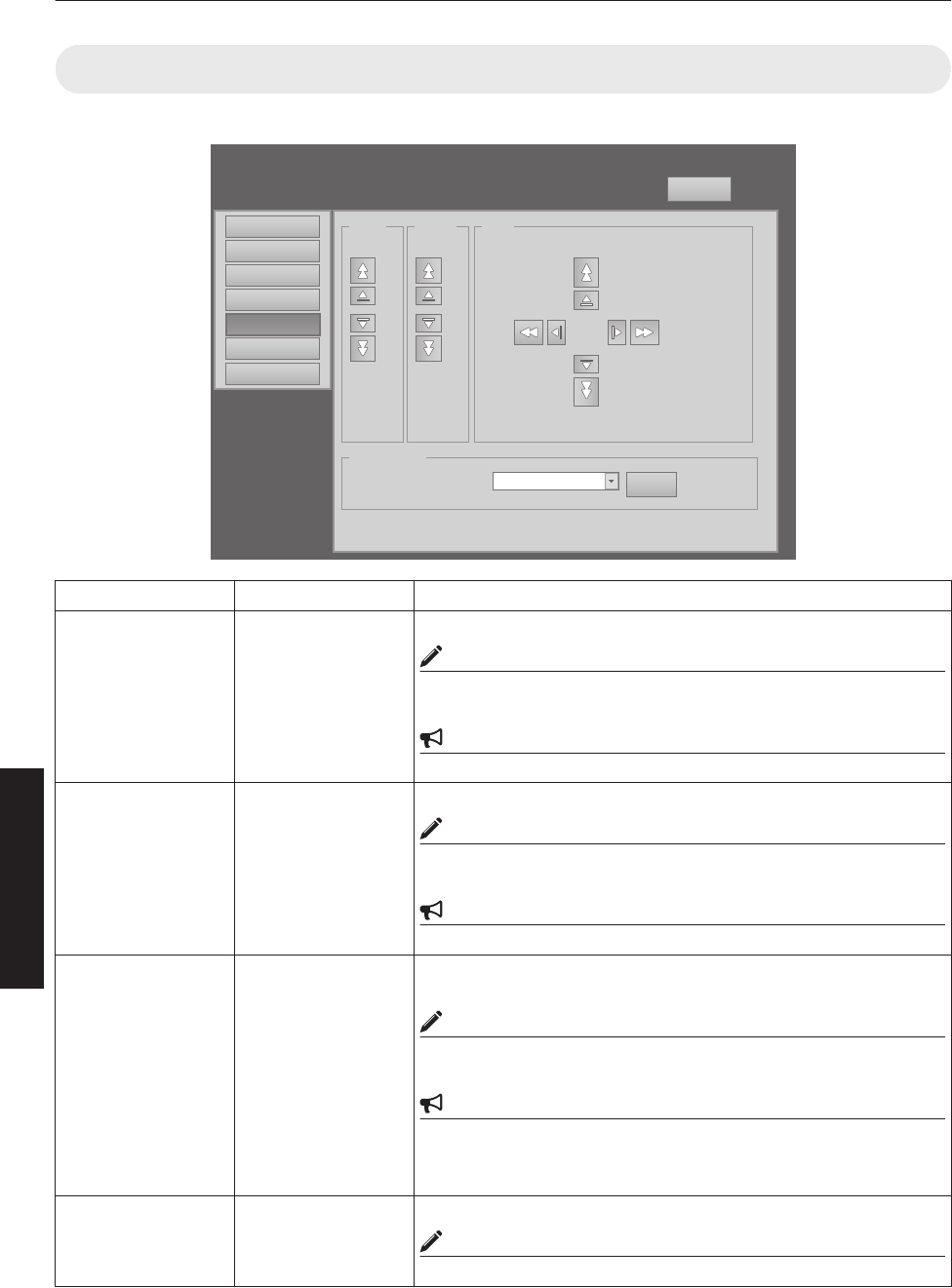
(5) Lens Menu
This menu is used for adjusting the projection lens.
.
Zoom
Setting
Convergence
Lens
Option
Logout
host PJ-1
user: root
Main
Image w
T
Focus
+
_
Shift
LR
U
D
Test Pattern
SET
OFF OFF
License
Item Setting Value Description
Zoom - For adjusting the zoom ratio (screen size).
MEMO
0The zoom position changes each time the inner button is clicked.
The zoom position changes when the outer button is depressed.
CAUTION
0Due to backlash, the response may not be immediate.
Focus - For adjusting the focus position.
MEMO
0The zoom position changes each time the inner button is clicked.
The zoom position changes when the outer button is depressed.
CAUTION
0Due to backlash, the response may not be immediate.
Shift - For adjusting the horizontal and vertical positions of the projection
screen.
MEMO
0The zoom position changes each time the inner button is clicked.
The zoom position changes when the outer button is depressed.
CAUTION
0When the movement exceeds the limit, the color of the button turns
red.
0Due to backlash, the response may not be immediate.
Test Pattern - For projecting the test pattern.
MEMO
0Same as “Test Pattern” in the “Convergence” Menu. (P. 39)
40
Operation and Settings
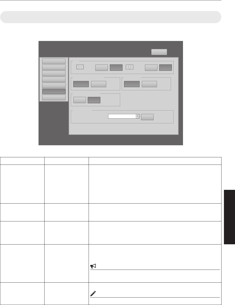
(6) Option Menu
This menu is used for specifying the settings for screen display method, LD block brightness and others.
.
Main
Image
Setting
Convergence
Lens
Option
Logout
host PJ-1
user: root
Flip
ON OFF
Back Color
Blue Black
Light Source Power
Horz.
ON OFF
Vert.
Test Pattern
SET
OFF OFF
Message Display
ON OFF
Mode1 Mode2
License
R indicates the factory default.
Item Setting Value Description
Flip
Horz.
Vert.
ON
R OFF
ON
R OFF
For specifying settings if images are vertically or horizontally flipped
when they are projected from the opposite side of the screen, or when
mirrors are used for projection.
ON : Flips image horizontally.
OFF : Do not flip image horizontally.
ON : Flips image vertically.
OFF : Do not flip image vertically.
Light Source Power R Mode1
Mode2
For switching the brightness of the LD block to “Mode1” or “Mode2”.
Mode1 : Brightness (high)
Mode2 : Brightness (low)
Back Color R Blue
Black
For specifying the background color during message display or when
projection fails, such as when there is no input signal.
Blue : Sets the screen to blue color.
Black : Sets the screen to black color.
Message Display ON
R OFF
For specifying whether to display the message.
ON : Displays message.
OFF : Does not display messages.
CAUTION
0When “OFF” is set, the “No Input”, “Out of Range” and “Lamp Time
Over” messages will not be displayed on the screen.
Test Pattern - For projecting the test pattern.
MEMO
0Same as “Test Pattern” in the “Convergence” Menu. (P. 39)
41
Operation and Settings

Administrator Settings Menu
After installation and connection are complete, perform the necessary adjustment and setting.
Operate the menus using the computer’s browser to make adjustments and configure settings.
Administrator Settings Menu Structure
For details on page menu (1) to (6), refer to “User Settings Menu” (P. 34 to 41).
Page Menu Name Page Display Item Simplified Description of Item
(1) Main Power
Warning Status
Light Source Time
Signal Status
Temperature
Hide
Power ON/OFF operation
Error code display
LD block information display
Input signal information display
Projector’s interior temperature display
Mute operation
(2) Image Brightness
Contrast
Gamma
Hide
Brightness adjustment
Contrast adjustment
Gamma setting
Mute operation
(3) Setting Input Level
Display Mode
Input level setting
Display method setting
(4) Convergence Red
Blue
Test Pattern
Pixel position adjustment
Pixel position adjustment
Test pattern setting
(5) Lens Zoom
Focus
Shift
Test Pattern
Zoom adjustment
Focus adjustment
Image position adjustment
Test pattern setting
(6) Option Flip
Light Source Power
Back Color
Message Display
Test Pattern
Image inversion setting
LD block power setting
Background color setting
Message display setting
Test pattern setting
(7) Admin.Network Host Name Setting
IP Address Setting
User Login Password Change
Admin. Login Password Change
Host name setting
IP address setting
User login setting
Administrator login setting
(8) Admin.E-mail E-Mail Setting
Test Mail
E-mail setting
Test e-mail setting
(9) Admin.Option Color Depth
Frame Lock
Mecha. Shutter
High Altitude
Light Source Time Reset
Color balance setting
Frame synchronization setting
Mechanical shutter setting
High altitude mode setting
Resetting the lifetime of LD block
(10) Admin.Signal Force Signal
Display Mode
Signal Status
EDID
Input/output signal setting
Display method setting
Input signal information display
EDID information rewrite
42
Operation and Settings
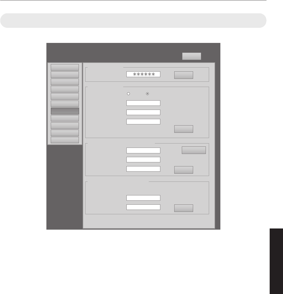
(7) Admin.Network Menu
For configuring the network settings.
.
Main
Image
Setting
Convergence
Lens
Option
Admin.Option
Admin.Signal
Admin.Network
Admin.Mail
Logout
host PJ-1
user: advanced
Host Name Setting
SET
Host Name
PJ
IP Address Setting
SET
DHCP Client DHCP
IP Address 192.168.1.100
User Login Name/Password Change
SET
Initialize
User Name root
New Password
Confirm
New Password
Admin. Login Password Change
SET
User Name advanced
New Password
Confirm
New Password
Subnet Mask 255.255.255.0
Default Gateway 192.168.1.1
Mac Address 01:23:45:67:89:AB
STATIC IP
License
43
Operation and Settings

R indicates the factory default.
Item Setting Value Description
Host Name Setting
Host Name
-
(Default Value: PJ******)
For specifying the host name.
MEMO
0You can change it to a random name. You can input up
to 8 characters using single-byte alphanumeric
characters and “-”.
0“******” of the default value displays the lower 3 bytes
of the MAC address of this projector.
IP Address Setting
DHCP Client
IP Address
Subnet Mask
Default Gateway
Mac Address
DHCP
R STATIC IP
(Default Value: 192.168.0.2)
(Default Value: 255.255.255.0)
(Default Value: 192.168.0.254)
-
For configuring the network settings.
DHCP : Select this to acquire the IP
address from the DHCP server
automatically.
STATIC IP : Select this to configure the IP
address manually.
IP Address : Specify the IP address.
Subnet Mask : Specify the subnet mask.
Default Gateway : Specify the default gateway.
Mac Address : Displays the MAC address.
(Cannot be specified)
User Login Name/
Password Change
User Name
New Password
Confirm New Password
Initialize
root
-
-
-
For changing the login name and password.
User Name : For changing the login name.
New Password : For changing the login password.
Confirm New
Password
: Re-enter the new password. (For
confirmation)
Initialize : For resetting the username/
password.
MEMO
0You can change it to a random name. You can input up
to 8 characters using single-byte alphanumeric
characters and “!”.
0If you have forgotten the password, please consult
your authorized dealer.
Admin. Login Password
Change
User Name
New Password
Confirm New Password
Initialize
advanced
-
-
-
For changing the administrator’s password.
User Name : Cannot be changed.(fixed)
New Password : For changing the login password.
Confirm New
Password
: Re-enter the new password. (For
confirmation)
Initialize : For resetting the password.
MEMO
0You can change it to a random name. You can input up
to 8 characters using single-byte alphanumeric
characters and “!”.
0If you have forgotten the password, please consult
your authorized dealer.
44
Operation and Settings
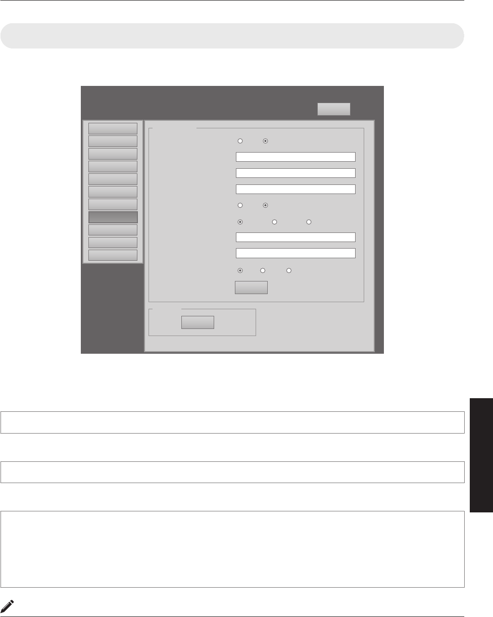
(8) Admin.E-mail Menu
This menu is for configuring the mail settings, which sends out an error message to the computer of the preset address
when an abnormality occurs within this projector.
.
Logout
host PJ-1
user: advanced
E-Mail Setting
Tset Mail
SET
SEND
E-Mail
E-Mail Sender
SMTP Server Address
E-Mail Auth.
Auth. Type
Auth. User Account
Auth. Password
Port No.
user@localhost
E-Mail Address
user@localhost
1.1.1.1
ON OFF
ON OFF
LOGIN CRAM-MD5PLAN
465 58725
Main
Image
Setting
Convergence
Lens
Option
Admin.Network
Admin.Option
Admin.Signal
Admin.E-Mail
License
Error message sent from this projector
(Example) When error occurs at the DD-RB board
Sender
****** (setting value for “E-Mail Sender”)
Mail title
4KPJU2 report mail
Message
Error Code 32 “Trouble with DD-RB circuit board.”
System Time 106 h 57 m
Light Source Time 41 h 57 m
Exhaust Temp. 42 deg.C
Inside Temp. 40 deg.C
Intake Temp. 24 deg.C
MEMO
0For details on the Error Code, refer to “Warning Status”P. 54.
45
Operation and Settings
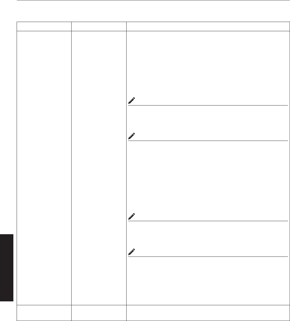
R indicates the factory default.
Item Setting Value Description
E-Mail Setting For configuring the e-mail feature.
E-Mail ON
R OFF
ON : Use the mail feature.
OFF : Do not use the mail feature.
E-Mail Sender -
(Default Value: lower 3
bytes of the MAC
address)
For specifying the destination e-mail address of this projector.
E-Mail Address -
(Default Value:
user@localhost)
For specifying the destination e-mail address.
MEMO
0Specify an address up to a maximum of 64 characters.
0Make use of single-byte alphanumeric characters and “-”“.”“_”“@”.
SMTP Server
Address
-
(Default Value:
1.1.1.1)
For specifying the address of the outgoing mail server (SMTP).
MEMO
0Specify an address up to a maximum of 15 characters.
0Make use of numbers and “.”.
E-Mail Auth. ON
R OFF
ON : Enable the e-mail authentication feature.
OFF : Disable the e-mail authentication feature.
Auth. Type R PLAIN
LOGIN
CRAM-MD5
For configuring the e-mail authentication type.
PLAIN : Set e-mail authentication to “PLAIN”.
LOGIN : Set e-mail authentication to “LOGIN”.
CRAM-MD5 : Set e-mail authentication to “CRAM-MD5”.
Auth. User Account - For configuring the account name during e-mail authentication.
MEMO
0Specify an address up to a maximum of 31 characters.
0Make use of single-byte alphanumeric characters and “-”.
Auth. Password - For configuring the password during e-mail authentication.
MEMO
0Specify an address up to a maximum of 31 characters.
0Make use of single-byte alphanumeric characters and “-”.
Port No. R 25
465
587
For configuring the SMTP server port number when using the e-mail
authentication feature.
Set - The details of the configuration will be saved.
Test Mail - When the “SEND” button is clicked, the test mail with the contents
configured in the “E-Mail Setting” will be sent.
46
Operation and Settings
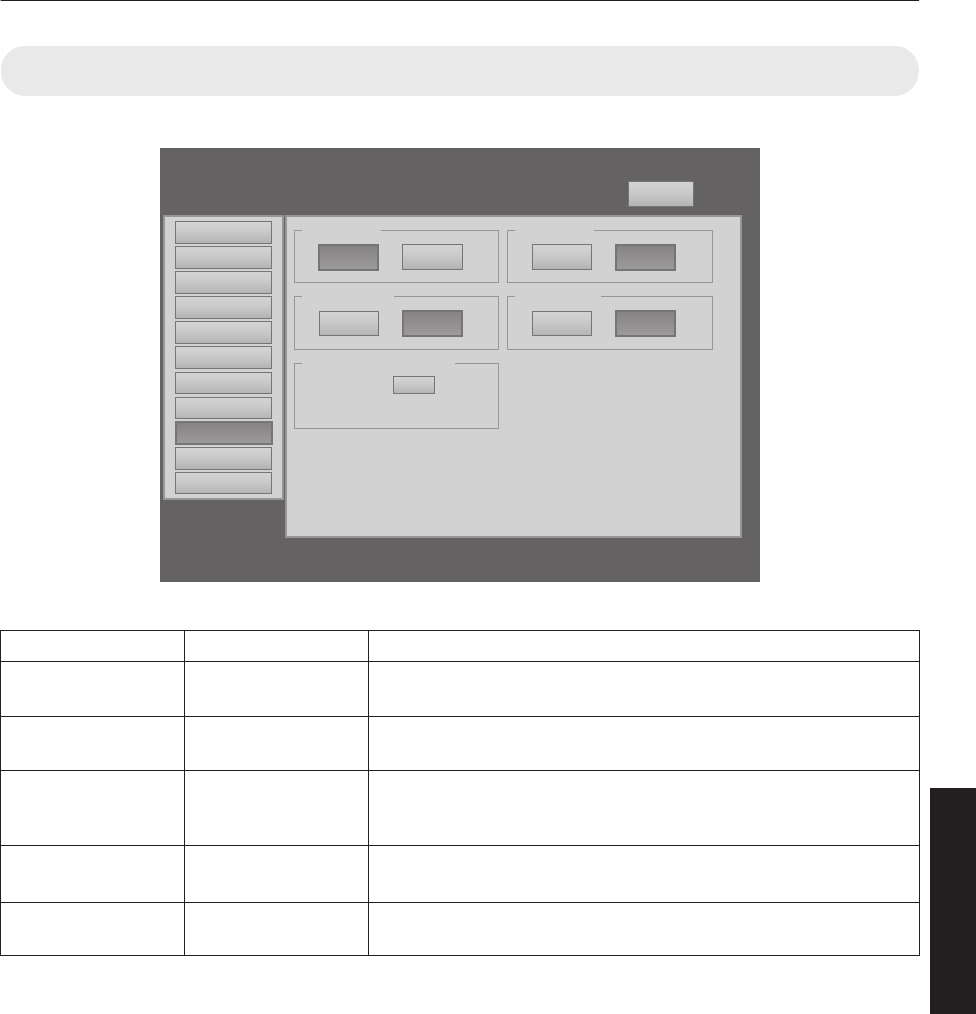
(9) Admin.Option Menu
This menu is used for specifying the image and option settings as well as resetting the lifetime of the LD block.
.
Logout
host PJ-1
user: advanced
Color Depth
8bit 12bit
Mech. Shutter
ON OFF
Light Source Time Reset
Reset
Frame Lock
ON OFF
High Altitude
ON OFF
Main
Image
Setting
Convergence
Lens
Option
Admin.Network 11h1m
Admin.Option
Admin.Signal
Admin.E-Mail
License
R indicates the factory default.
Item Setting Value Description
Color Depth R 8bit
12bit
For configuring the color balance.
Frame Lock R ON
OFF
For configuring the frame synchronization of each DVI input.
Mech. Shutter ON
R OFF
For configuring to ON/OFF the Mech. Shutter (model number: PK-
VS4MS, optional, sold separately). Click “ON” to operate the Mecha
Shutter.
High Altitude ON
R OFF
Configure to “ON” when using at high altitude (above 1,500 m).
Light Source Time
Reset
- Resets the lifetime of the LD block.
47
Operation and Settings
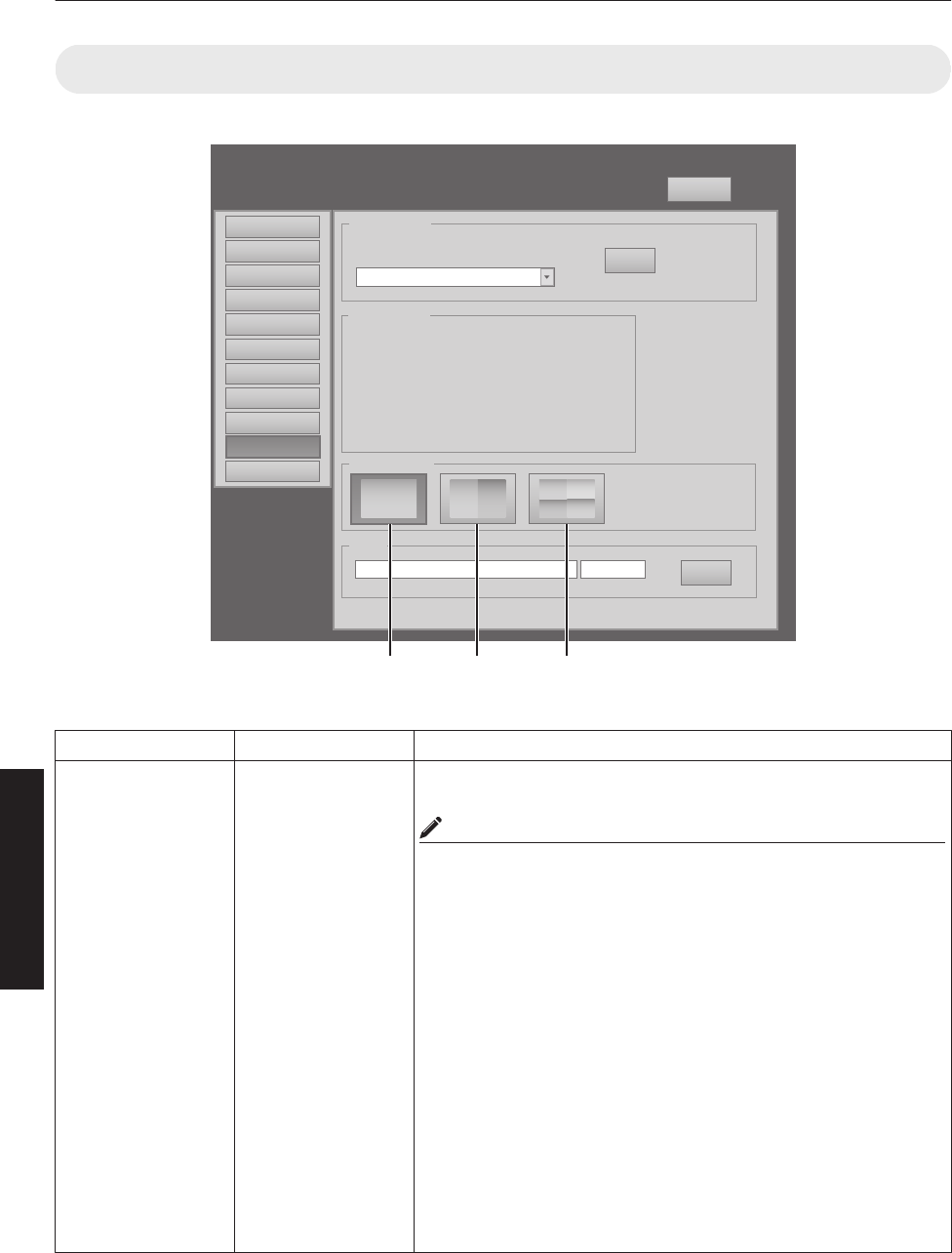
(10) Admin.Signal Menu
This menu is for configuring settings such as display format, and for rewriting EDID.
.
Logout
host PJ-1
user: advanced
Display Mode
11 3
312
4
Main
Image
Setting
Convergence
Lens
Option
Admin.Network
Admin.Option
Admin.Signal
Admin.E-Mail
EDID
SET
Force Signal
SET
OFF
OFF
DVI Rate(Hz) Pixel H Pixel V Link
1 60.00 2048 2400 Dual
2
3 60.00 2048 2400 Dual
4
Signal Status
License
Browse...
Single Double Cross
R indicates the factory default.
Item Setting Value Description
Force Signal R OFF
4096×2400, None,
Dual
4096×2400, None,
Single
2048×2400,
2Stripe, Dual
2048×2400,
2Stripe, Single
2048×1200, Cross,
Dual
2048×1200, Cross,
Single
1024×2400,
4Stripe, Dual
1024×2400,
4Stripe, Single
For forcibly configuring the output signal. Make use of this setting when
there is no display due to configuration changes at the input source.
MEMO
0Some portions of the image may not be displayed and the image
may become noisy.
OFF : Turns off the display by force.
4096×2400,
None, Dual
:Displays a normal screen using dual link.
4096×2400,
None, Single
: Displays a normal screen using single link.
2048×2400,
2Stripe, Dual
: Displays a 2 stripes screen using dual link.
2048×2400,
2Stripe, Single
: Displays a 2 stripes screen using single link.
2048×1200,
Cross, Dual
: Displays a cross screen using dual link.
2048×1200,
Cross, Single
: Displays a cross screen using single link.
1024×2400,
4Stripe, Dual
: Displays a 4 stripes screen using dual link.
1024×2400,
4Stripe, Single
: Displays a 4 stripes screen using single link.
48
Operation and Settings
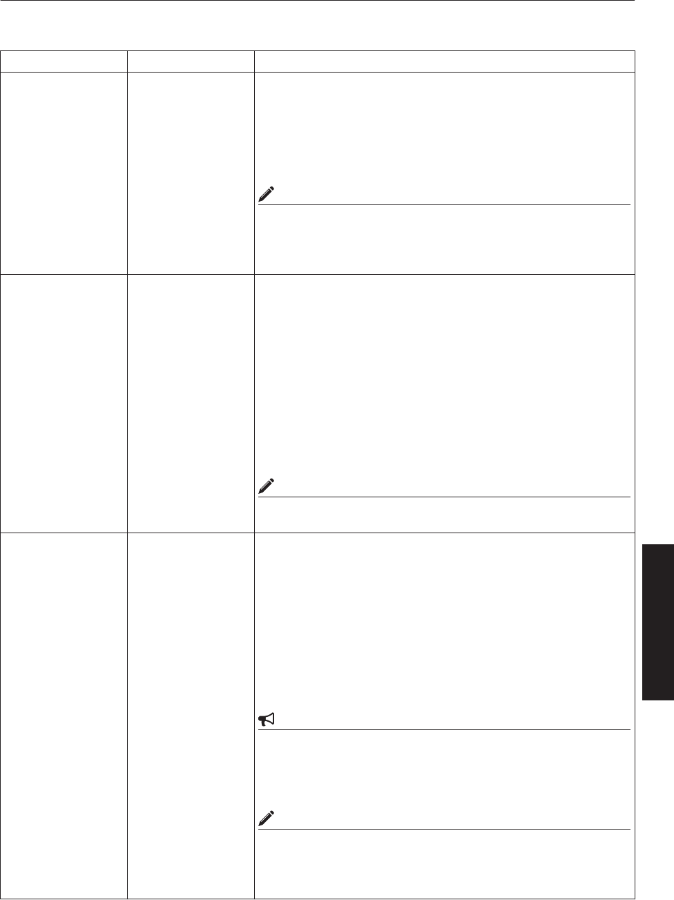
R indicates the factory default.
Item Setting Value Description
Signal Status
DVI
Rate(Hz)
Pixel H
Pixel V
Link
-
-
-
-
-
Displays information on the input signals. Same as “Signal Status” in
the User Menu.
DVI : Displays the DVI input terminal number.
Rate(Hz) : Displays the vertical frequency.
Pixel H : Displays the horizontal resolution.
Pixel V : Displays the vertical resolution.
Link : Displays the link status of the DVI terminal.
MEMO
0This item is not displayed when there is no signal input.
0The text color of “Rate(Hz)” (vertical frequency) turns red in the
case of interlaced signal. And the text turns white in the case of
progressive signal.
Display Mode R Single
Double
Cross
For specifying the display mode of the projection screen. Same
configuration as “Display Mode” in the User Menu.
Single : Displays input signals on a single screen.
Double : Displays two different input signals on two screens.
The left screen displays images of the [DVI 1] terminal,
and the right screen displays images of the [DVI 3]
terminal.
Cross : Displays four different input signals on four screens.
The top left screen displays images of the [DVI 1]
terminal, the top right screen displays images of the [DVI
2] terminal, the bottom left screen displays images of the
[DVI 3] terminal, while the bottom right screen displays
images of the [DVI 4] terminal.
MEMO
0Please refer to “Connecting Video Signals of the Computer” for
details. (P. 18 to 21)
EDID - For rewriting EDID.
Click the “Browse” button and select an EDID file.
Click the “SET” button to start writing.
Write “OK” will be displayed for each channel. “NG (number)” is
displayed when writing fails.
Error Code
1: System error
7 : Unable to execute due to power off
8 : Unable to rewrite due to DVI cable connection
CAUTION
0Do not turn off the power during rewrite.
0The EDID file capacity is within 256 byte.
0Rewriting to individual channel is not available.
0It is not possible to move on to other pages during rewrite.
MEMO
0EDID: Extended Display Information Data
A data to describe the specifications (resolution, model number, etc.)
of the projector. The compatible transmitting device will output the
optimum video signal based on this data.
49
Operation and Settings

Troubleshooting
Check the following points before sending this product for repair.
The following phenomena are not malfunctions.
If there is no abnormality on the screen when the phenomena below appear, they are not
malfunctions.
0The top or front part as well as the rear of the projector unit is hot
0A creaking sound is heard from the projector
0Device noise is heard from the interior of the projector
0There is color bleeding on the screen
When the projector fails to run properly due to external noises, perform the following operations.
ACheck to ensure that the power is shut down. Unplug the power cord, and insert again.
BTurn on the power of the projector
A sound maybe heard when the lamp burn out. However, this is not a hazard.
D-ILA devices are manufactured using extremely high-precision technology. However, some of
the pixels may not lit up or remain permanently lit up.
Symptom Probable Cause Corrective Action Reference
Page
Power is not supplied 0Is the power cord
disconnected?
0Insert the power cord (plug) properly. P. 24
0Is the main power supply
switched turned on?
0Turn on the main power supply switch of
the projector unit. P. 24
0Is the LD block in the cool down
mode?
0Turn on the power again after the cool
down mode ends. P. 31
0Is the LD block protection
function triggered?
(This function is triggered when
the power shuts down such as
during power failures.)
0Wait until the temperature of the LD block
drops. (Turn on the main power supply
switch to run the fan to cool down the LD
block.) Turn on the projector after about
10 seconds.
-
Image is dark
0Is the LD block near
exhaustion?
0Check the “Light Source Time” in the
“Main” menu. When the LD block is near
exhaustion, please consult your
authorized dealer.
P. 36
Projector works when
the power is turned on,
but stops abruptly after
a few minutes
0Are the air inlets and vent holes
blocked?
0Turn off the main power supply switch,
and remove the blockage. After
removing, turn on the power again.
P. 9 to 11,
P. 32
0Is the temperature of the room
high?
0Set the temperature of the room or the
surrounding temperature of this projector
to an appropriate level.
P. 60
0Are the filters dirty? 0Clean the filters. P. 57
50
Others

Video image does not
appear
0Is the lens cap removed? 0Remove the lens cap. P. 9
0Are devices properly
connected?
0Connect the devices correctly. P. 19, 21
0Is the power of the connected
devices turned on?
0Turn on the power of the connected
devices. -
0Are correct signals being output
from the connected devices?
0Configure the connected devices
correctly. -
0Are the signals of the
connected devices possible
input signals?
0Check to ensure that they are possible
input signals, and input compatible
signals accordingly.
P. 18, 18
0Is the image temporarily
hidden?
0Set “Hide” of the “Main” menu or “Image”
menu to “OFF” to display the image. P. 32, 36, 37
Video image is blur 0Is the projector out of focus?
0Adjust the focus using “Focus” of the
“Lens” menu. P. 31, 40
0Is the projection distance too
short or too long?
0Set it to a correct distance. P. 16, 17
Image is unusually
dark or bright 0Is the brightness level properly
adjusted?
0Adjust accordingly using “Brightness” of
the “Image” menu.
0Adjust “Light Source Power” in the
“Option” menu.
P. 37
P. 41
Coloring of the image
is poor or distorted
0Is the contrast level properly
adjusted?
0Adjust accordingly using “Contrast” of
the “Image” menu. P. 37
0Are the signals of the
connected devices possible
input signals?
0Check to ensure that they are possible
input signals, and input compatible
signals accordingly.
P. 18, 20
0Is the input cable correctly
connected?
0Connect the input cable correctly. P. 19, 21
Projection position on
the screen has shifted
0Has the setup position of the
projector been shifted?
0Check the setup position of the projector. -
Image disappears
suddenly
0Are the video signals correctly
input?
0Check the signals and connection. P. 18 to 21
Images do not appear
on the two-screen
mode display
0Are the [DVI 1] and [DVI 3]
terminals connected for input?
0To display images in the two-screen
mode, connect the [DVI 1] and [DVI 3]
terminals. The left screen displays
images of the [DVI 1] terminal, and the
right screen displays images of the [DVI
3] terminal.
P. 20, 21
Images do not appear
immediately after
power is turned on
0Formatting is in progress.
0Please wait for a maximum duration of 3
minutes for the formatting progress to
end.
P. 29
The screen does not
darken immediately
when the projection
has ended
0The ending process is in
progress.
0Please wait for a maximum duration of 2
minutes for the ending progress to
complete after several hours of image
projection.
P. 31
The MENU is not
displayed correctly
0It may be affected by your Web
browser cache (temporary file
storage).
0Delete all Web browser cache
(temporary file storage). -
51
Others
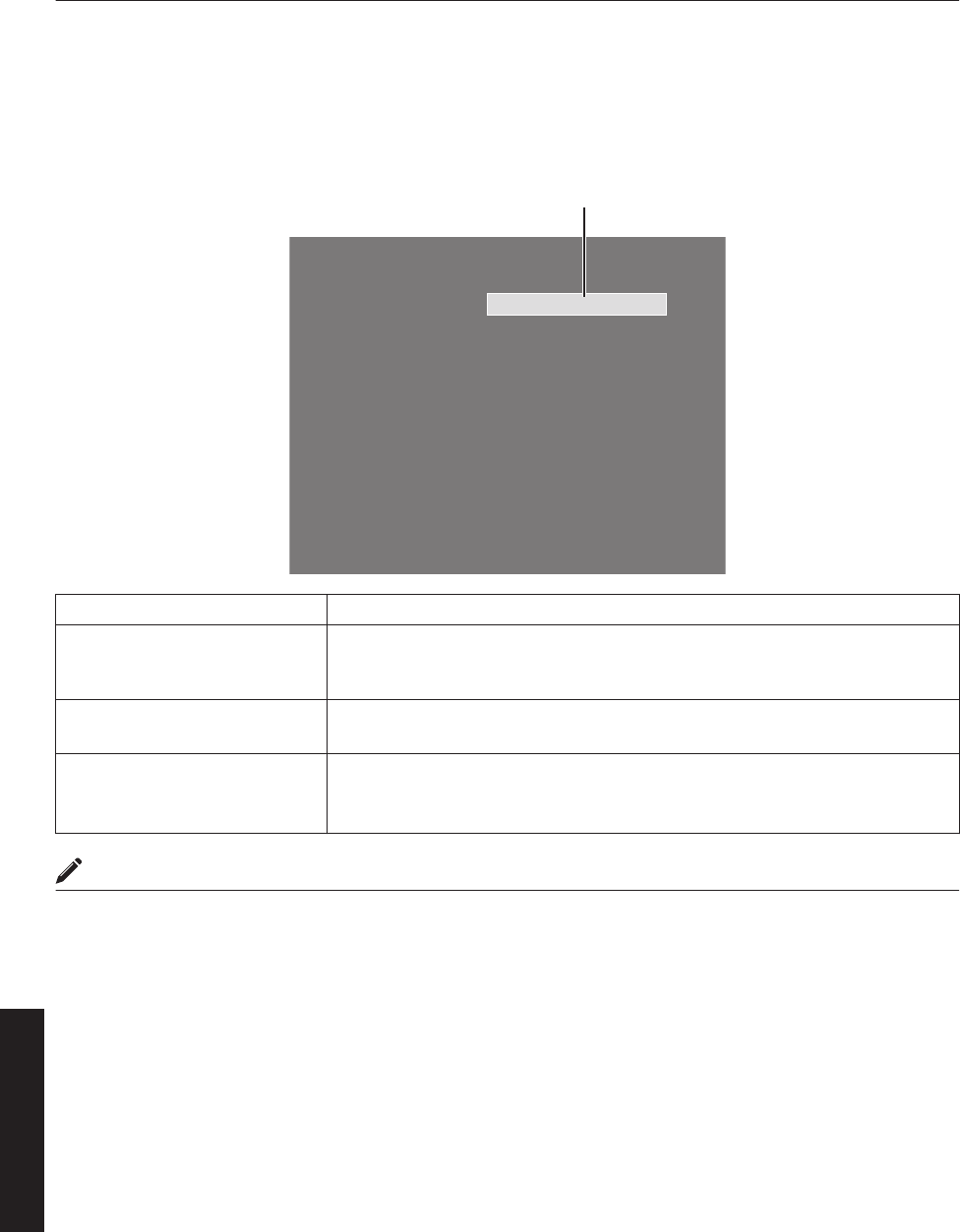
What to do when these messages are
displayed
Messages are displayed when the LD block is exhausted or when a signal that is not usable is input.
.
Lamp Time Over
Message
Message Cause (Details)
Lamp Time Over
0Displayed when the lifetime of the LD block has exceeded 20,000 hours.
The message is displayed for 3 minutes during each projection.
" For details, please consult your authorized dealer.
Out of Range
0When there is input of video signals that cannot be used with this unit
" Input video signals that can be used.
No Input
0When no device is connected to the input terminal
0When the input terminal is connected but there is no signal
" Input the video signals.
MEMO
0The messages will not be displayed under factory default conditions.
0Set “Message Display” in the “Option” menu to “ON”. (P. 41)
52
Others
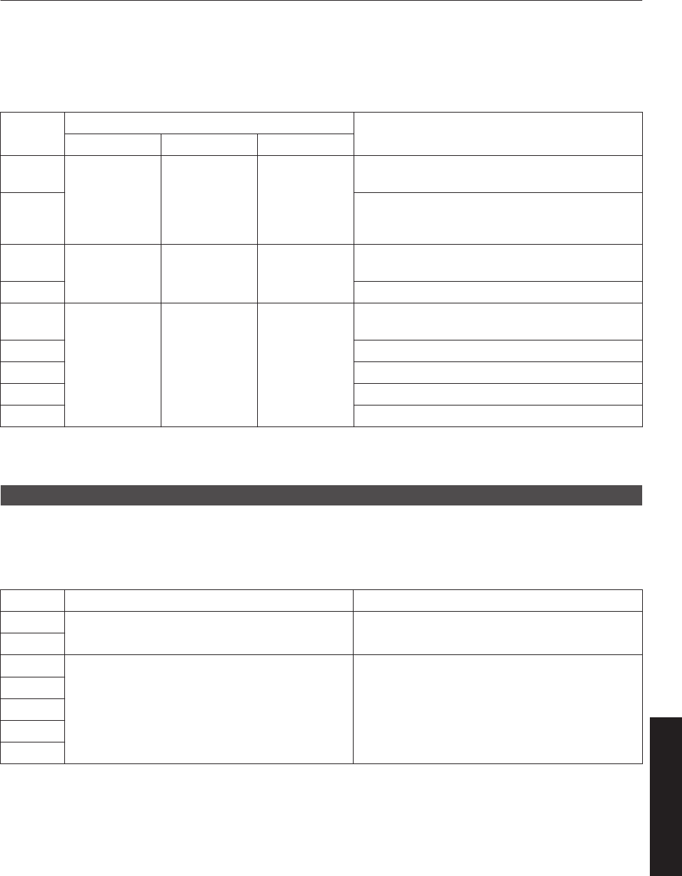
Warnings Using Indicators
The lifetime of the LD block and warning mode are indicated by the indicators.
For indicator displays during normal operation, refer to the note below.
No. Indicator Description
STANDBY/ON LAMP WARNING
1
*1 Light On
(Yellow) -
When the lifetime of the LD block has exceeded
19,000 hours
2
When the lifetime of the LD block has exceeded
20,000 hours
(Message display is also available. (P. 52))
3*2 Blinking
(Yellow)
Light On
(Red)
When the LD block does not light up and projection
fails
4 When the LD block goes off during projection
5
*2 - Light On
(Red)
When the ambient temperature of the LD block is
high
6 When the external temperature is unusually high
7 When the internal temperature is unusually high
8 When an abnormality has occurred in the cooling fan
9 When error occurs in the circuit operation
*1 The indicator lights up in red when in the standby mode, and in green when in the operating mode.
*2 The indicator lights up in red when in the warning mode, and blinks in red when in the cool down mode.
Measures when the warning mode appears
When the projector switches to the warning mode (Nos. 3 to 9), projection stops automatically, and the cooling fan runs
for about 10 seconds.
After the cooling fan stops running, turn off the main power supply switch, and remove the power plug from the outlet.
Perform the following checks and take the corresponding measures.
No. Check Measure
30Check whether the projector has been subject to
shock during operation.
0Turn on the power again.
4
5
0Check whether the air inlets are blocked by
objects.
0Check to ensure that the external temperature of
the projector is normal.
0Allow some time for the projector to cool down.
6
7
8
9
If the warning indication is displayed again, turn off the main power supply switch after the cooling fan stops running.
Then pull out the power plug from the power outlet. Call your authorized dealer for repair.
53
Others
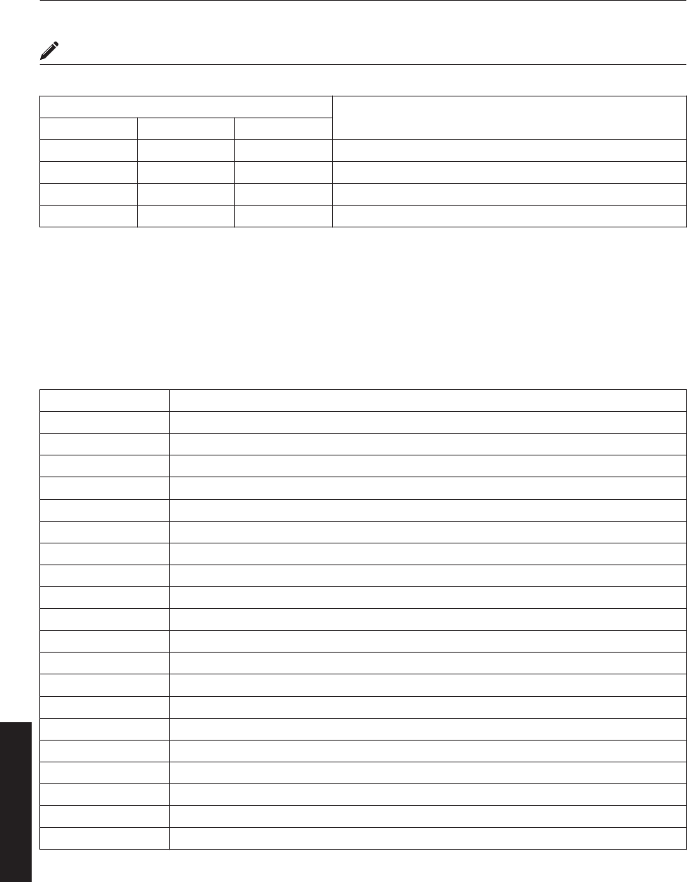
MEMO
0Indicator display during normal condition.
Indicator Description
STANDBY/ON LAMP WARNING
Light On (Red) - - When in the standby mode.
Light On (Green) - - When power is supplied (operating mode).
Blinking (Red) - - When cooling down (cool down mode). (P. 31)
Blinking (Green) - - When the projected image is temporarily hidden. (P. 32)
Warning Status
The latest error code (Warning Status) appears in the “Main” menu when an abnormality occurs in the projector.
Error details are as follows:
Error Code Meaning
2 The lifetime of the LD block has exceeded 20,000 hours.
8 Abnormally high temperature in the projector.
9 Abnormally high temperature around the intake vent.
A Abnormally high ambient temperature around the lamp.
15 The safety switch is activated.
30 Trouble with CPU circuit board.
31 Trouble with MAIN circuit board.
32 Trouble with DD-RB circuit board.
33 Trouble with DD-G circuit board.
34 Trouble with SUB CPU circuit board.
41 Cooling fan for the illumination system (PCS) has stopped.
42 Cooling fan for the circuit power has stopped.
43 Cooling fan for the DD circuit board has stopped.
44 Cooling fan for the MAIN circuit board has stopped.
46 Cooling fan for the PFC power has stopped.
48 Cooling fan for the DD RB has stopped.
4A Exhaust fan for the LD Driver has stopped.
4B Cooling fan for the LD Bank1 has stopped.
4C Cooling fan for the LD Bank2 has stopped.
50 Trouble with mechanical shutter.
54
Others
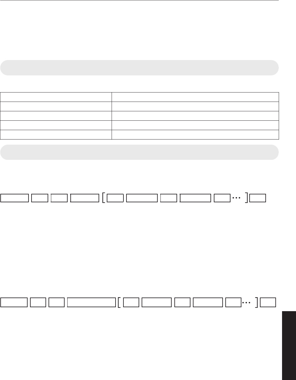
RS-232C Interface
You can control this projector via a computer by connecting the computer to this unit using a RS-232C cross cable (D-
sub 9 pins).
The commands to control this unit and the response data format against the received commands are explained here.
For details, please consult your authorized dealer.
Communication Specifications
Communication specifications for this unit are as follows:
Transfer Rate 19200 bps
Data Length 8 bit
Parity None
Stop Bit 1 bit
Flow Control None
Command Format
Command Data Format (PC"Projector)
When sending a control command to this unit, use the following data format:
.
ID SP SP SP SP CR
Command
ParameterParameterHeader
Header : Designates the head of data and the data type.
“!” (21h): Assigns command to the projector (Command)
“?” (3Fh): Query to the projector (Asking command)
ID : “1”: Identification number of the projector (Factory setting is “1”)
SP : Designates the delimiter between ID and command, command and parameter, as well as
parameter and parameter. (20h)
CR : Designates the terminal of the data. (0Dh)
* [ ] is not necessary for Asking command.
Response Data Format (Projector"PC)
Upon executing a control command, this unit sends back response data to the computer in this format.
.
ID SP SP SP SP CR
ParameterParameter
Normal Termination Status
Header
Header : Designates the head of the response data.
“@” (40h): Fetches data from the projector
ID : “1”: Identification number of the projector (Factory setting is “1”)
SP : Designates the delimiter between ID and normal termination status, normal termination status
and parameter, as well as parameter and parameter. (20h)
Normal Termination
Status
: “0” (30h)
CR : Designates the terminal of the data. (0Dh)
* [ ] is not applicable when sending commands to the projector.
55
Others

Parameters used for the data format
The following 2 types of parameters are used for command and response data:
(1) ON/OFF (2) Special Parameter
Each parameter is as follows:
(1) ON/OFF
Shows the status (ON or OFF) of the unit, such as POWER and HIDE.
Character Hex Meaning
0 30 OFF
1 31 ON
(2) Special parameters
Operation mode parameters
Character Hex Meaning
0 30 Standby state
1 31 Power ON state
2 32 Cooling state
3 33 Emergency cooling state
4 34 Emergency state
DHCP client parameters
Character Hex Meaning
0 30 DHCP
1 31 STATIC IP
IP address parameters
Display the IP address using the dot (“.” (2HE)) delimiter.
Example: “192.168.0.10”
External control command table
Function Command Setting Asking Data Type
Power On ELSE Power On ELSE ON/OFF Special Parameter
Power U0F X (OFF) X (ON) - - X-
Hide U00 X-X-X-
Operation Mode UA0 - - X X - Standby...
DHCP Client UD2 XXXX - DHCP...
IP Address UD3 XXXX - 192.168. ...
Network Restart UDC XXXX - “0” Fixed
MEMO
0After configuring “DHCP Client” and “IP Address”, execute “Network Restart”.
56
Others
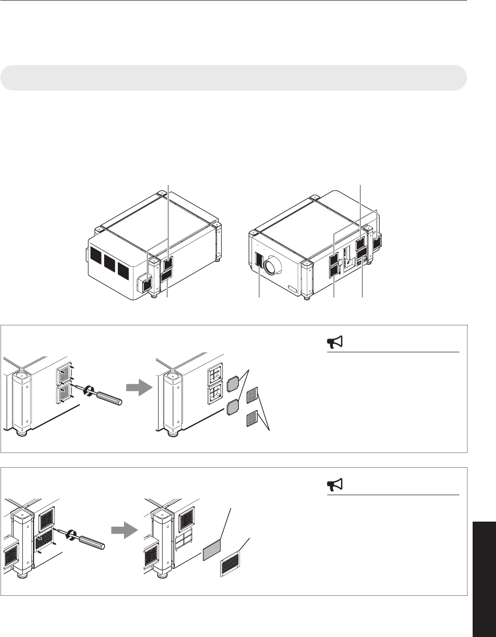
Maintenance
Turn off the power of the projector unit, and unplug the power cord when cleaning or replacing the filter.
Cleaning and Replacing the Filter
Clean the filter regularly. If the filter is soiled, air intake efficiency may deteriorate, thus resulting in malfunction of the
product.
Replace with a new one if the filter fails to remove dust thoroughly or if it is damaged. Failure to do so may cause dust
to enter the projector and shadows to appear on the projected image.
If dirt has entered this product or if you need to purchase the filter, please consult the authorized dealer from which this
product is purchased or any nearby JVC servicing center.
.
A A
B A BC
CAUTION
0Remove the four screws on
the inner side (for fastening
the filter cover).
A
Filter Cover
Sponge
CAUTION
0Remove the four screws on
the inner side (for fastening
the filter cover).
B
Filter Cover
Sponge
57
Others
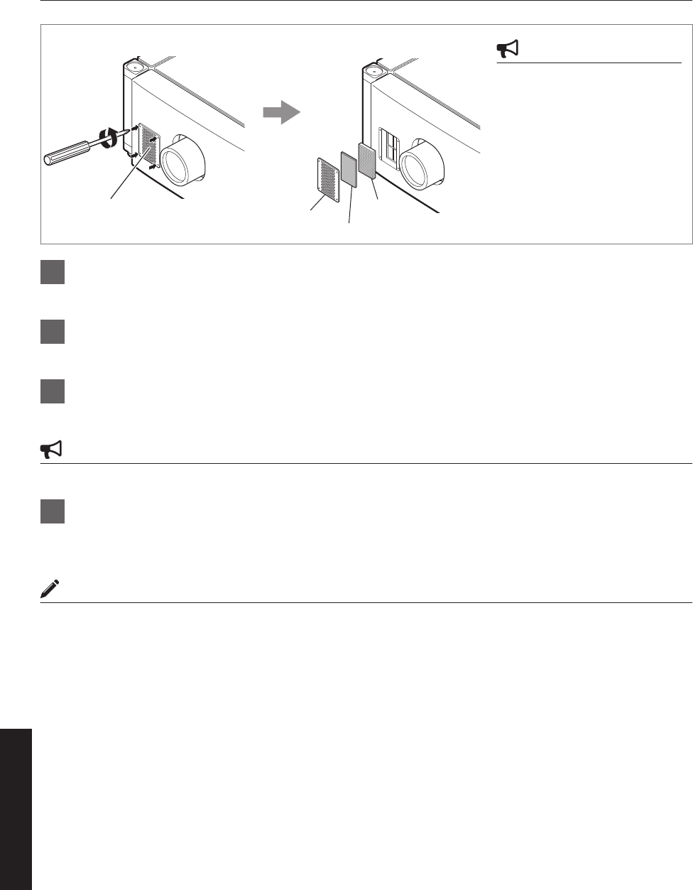
CAUTION
0Remove the four screws on
the inner side (for fastening
the filter cover).
C
Filter
Filter Cover Filter Cover
Sponge
1Remove the filter cover
The filter is located at the front side of the projector unit.
2Remove the sponge and filter
Hold the center of the filter using your fingers, and pull the filter toward you to remove it.
3Clean the sponge and filter
Remove any dirt or dust using a vacuum cleaner.
CAUTION
0Do not clean using a flammable air duster. This may cause fire.
4Mount the sponge and filter
Mount the filter and sponge to the projector using the reverse removed procedure.
Finally, check to ensure that the filter cover is firmly mounted.
MEMO
0Mount the filter correctly. Failure to do so may cause the projector to malfunction.
0The projector may stop operating if a damaged filter or filter panel is used. In this case, replace the filter or filter panel
with a new one.
58
Others

Routine Servicing
Clean dirt on the cabinet
Do this with a soft cloth. In case of heavy soiling, soak a cloth in neutral detergent diluted with water, wring dry and
wipe, followed by wiping again using a dry cloth.
Pay attention to the following to prevent the cabinet from deteriorating in condition, getting damaged, or the paint from
coming off.
0Do not wipe with a stiff cloth
0Do not wipe with force
0Do not wipe with thinner or benzene
0Do not spray volatile chemicals like insecticide
0Do not allow prolonged contact with rubber or plastic products
Remove dirt that is attached to the vent holes
Do this using a vacuum cleaner. Wipe using a cloth if a vacuum cleaner cannot be used. Leaving dust attached may
prevent adjustment of the internal temperature and result in malfunction of the projector.
Clean dirt on the lens
Do this using commercial blowers or lens cleaning papers (for cleaning glasses and cameras).
Do not use fluid-type cleaning agents. This may lead to peeling of the surface coating film.
Lens surface is fragile. Avoid rubbing or knocking it.
59
Others
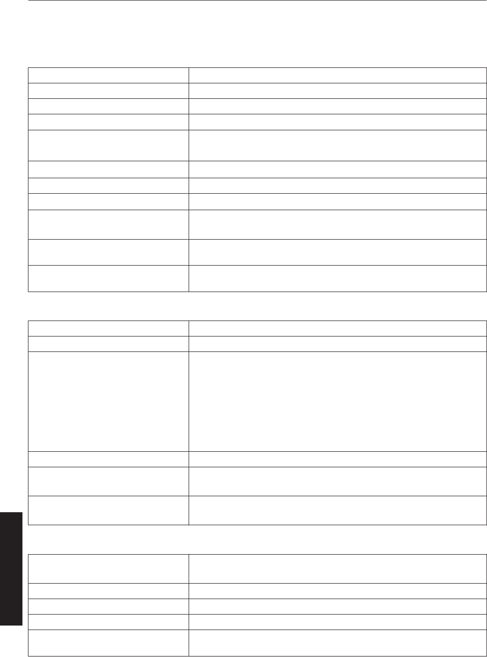
Specifications
General
Power supply AC 110 to 240 V, 50 Hz/60 Hz
Power consumption 1250 W (Standby mode: 7 W)
Current consumption 11.5 A max (AC 110 to 240 V)
Calorific power 4500 kJ/h (1076 kcal/h)
Air capacity Intake: Approx. 6 m3/min
Exhaust: Approx. 6 m3/min
Allowable operating temperature range 10°C to 35°C
Allowable operating humidity range 20% to 80% (non-condensation)
Allowable storage temperature range -5°C to 60°C
Installation height Operation guarantee: 2000 m and below
Performance guarantee: 1500 m and below
Dimensions 660 mm x 342 mm x 934 mm (Width x Height x Depth)
(Excluding lens and small protrusions)
Mass DLA-VS4010: 73.5 kg (Excluding lens)
DLA-VS4810: 74.5 kg (Excluding lens)
Optical System
Projection method D-ILA analog drive system × 3
D-ILA element *1*2 1.27" (4096×2400 pixels) × 3 pcs (total no. of pixels: 29,491,200 pixels)
Projection Lens (optional)
GL-MS4015SZ
(1.50:1 to 1.84:1 zoom lens)
GL-MS4016SZ
(1.50:1 to 1.84:1 zoom lens)
GL-MS4021SZ
(2.15:1 to 3.65:1 zoom lens)
GL-MS4011S
(1:1.1 Short focal length lens)
Light-source Lamp Laser diode
Screen size 80" to 300" (zoom lens)
50" to 250" (short focal length lens)
Projection distance Approx. 2.6 m to 12 m (zoom lens)
Approx. 1.2 m to 6 m (short focal length lens)
Terminal
Video input DVI-D (dual link) 24 pins
(supports 12-bit extended input) × 4 (supports HDCP*3)
LAN RJ45 × 1
USB Type B (Slave) × 1
RS-232C D-sub 9 pins (male) x 3
e-shift Sync
(DLA-VS4810 only)
BNC (male) × 1
(3.3 V CMOS input level, high impedance)
60
Others

Optional Items
Projection lens
GL-MS4015SZ
01.50:1 to 1.84:1 1.22x zoom lens (80" to 300")
GL-MS4016SZ
01.50:1 to 1.84:1 1.22x zoom lens (50" to 210")
GL-MS4021SZ
02.15:1 to 3.65:1 1.69x zoom lens (80" to 300")
GL-MS4011S
01:1.1 short focal length lens (50" to 250")
Replacement filter/sponge (front)
LC43010-003A (Filter)
LC43030-003A (Sponge)
Replacement sponge (right/left side)
LC43030-002A
J3K-0072-00
*1 D-ILA is the abbreviation for Direct Drive Image Light Amplifier.
*2 D-ILA devices are manufactured using extremely high-precision technology with a pixel effectiveness of 99.99%.
Only 0.01% or less of the pixels are either missing or would remain permanently lit.
*3 HDCP is the abbreviation for High-bandwidth Digital Content Protection system. Images from the DVI input
terminal may not be displayed due to HDCP specification changes.
0The open source software is embedded in this product. For more information, please go to:
http://www3.jvckenwood.com/english/download/lnx/07jvc-pj/
0Design and specifications are subject to change without prior notice.
0Please note that some of the pictures and illustrations may have been abridged, enlarged or contextualized in order
to aid comprehension. Images may differ from the actual product.
61
Others
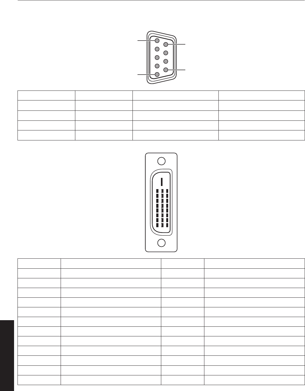
Pin Arrangement
0RS-232C Terminal
.
5
1
9
6
Pin No. Signal Action Signal Direction
2 RxD Incoming Data PC " This Projector
3 TxD Outgoing Data This Projector " PC
5 GND Signal Ground -
1, 4, 6-9 NC - -
0DVI-D Terminal
.
8
16
24
7
15
23
6
14
22
3
11
19
2
10
18
5
13
21
4
12
20
1
9
17
Pin No. Signal Pin No. Signal
1 TMDS Data 2- 13 TMDS Data 3+
2 TMDS Data 2+ 14 TMDS +5 V Power Supply
3 TMDS Data 2/4 Shield 15 Earth (+5 V)
4 TMDS Data 4- 16 Hot Plug Detection
5 TMDS Data 4+ 17 TMDS Data 0-
6 DDC Clock 18 TMDS Data 0+
7 DDC Data 19 TMDS Data 0/5 Shield
8 NC 20 TMDS Data 5-
9 TMDS Data 1- 21 TMDS Data 5+
10 TMDS Data 1+ 22 TMDS Clock Shield
11 TMDS Data 1/3 Shield 23 TMDS Clock +
12 TMDS Data 3- 24 TMDS Clock -
TMDS = Transition Minimized Differential Signaling
DDC = Display Data Channel
62
Others
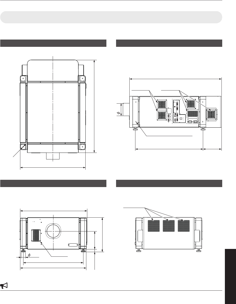
Dimensional Outline Drawing
(Unit: mm)
Top Surface
.
660
M10
934
Front
.
676.5
181.5
43.5
600
660
26 to 46
342 to 362
Intake air
Side
.
OPERATE I/B
DVI 3
USB
LAN
RS-232C
STANDBY/ON
LAMP
WARNING
DVI 4
DVI 1
DVI 2
e-shift Sync
RS-232C
1
2
934
688 187
127
Tightening depth: 10 to 20
M10 hole (x 12)
Intake airIntake air
Rear Surface
.
Exhaust air
CAUTION
0Using screws with dimensions other than those specified in the above diagram may cause the projector to drop or
malfunction.
63
Others

.
DLA-VS4010
DLA-VS4810
D-ILA PROJECTOR
Importer (EU only)
12 Priestley Way, London NW2 7BA, UNITED KINGDOM
Importeur (Nur EU)
Konrad-Adenauer-Allee 1-11, 61118 Bad Vilbel, DEUTSCHLAND
Importatore (Solo EU)
Via G. Sirtori 7/9, 20129 Milano, ITALIA
Importador (Solamente EU)
Ctra. Rubi, 88 Edifi cio Can Castanyer, 08174 Sant Cugat del Valles,
Barcelona, ESPAÑA
Importeur (Alleen EU)
Leuvensesteenweg 248J, 1800 Vilvoorde, BELGIQUE
Importeur (Alleen EU)
Amsterdamseweg 37, 1422 AC Uithoorn, NEDERLAND
Manufacturer
3-12, Moriya-cho, Kanagawa-ku, Yokohama-shi, Kanagawa,
221-0022, JAPAN
© 2017 JVCKENWOOD Corporation 1217KSY-SW-X
