JVC FS SD1000 User Manual TABLETOP SYSTEM Manuals And Guides L0209261
JVC Tabletop Systems Manual L0209261 JVC Tabletop Systems Owner's Manual, JVC Tabletop Systems installation guides
User Manual: JVC FS-SD1000 FS-SD1000 JVC TABLETOP SYSTEM - Manuals and Guides View the owners manual for your JVC TABLETOP SYSTEM #FSSD1000. Home:Electronics Parts:Jvc Parts:Jvc TABLETOP SYSTEM Manual
Open the PDF directly: View PDF ![]() .
.
Page Count: 30
JVC #IIII/////
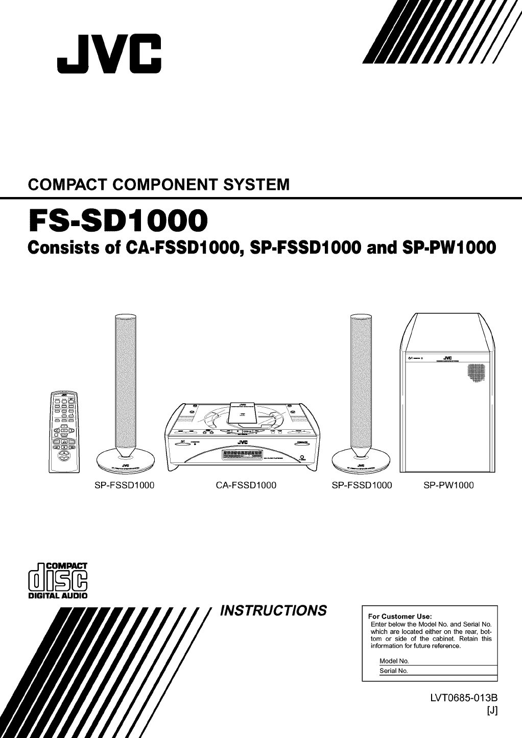
COMPACT COMPONENT SYSTEM
FS.SDIO00
Consists of CA.FSSD1000, SP-FSSD1000 and SP.PWl000
SP-FSSD1000 CA-FSSD1000 SP-FSSD 1000 SP-PWl000
DIGITAL AUDIO
INSTRUCTIONS For Customer Use:
Enter below the Model No. and Serial No.
which are located either on the rear, bot-
tom or side of the cabinet. Retain this
information for future reference.
Model No.
Serial No.
LVT0685-013B
[J]
Warnings, Cautions and Others /
Mises en garde, precautions et indications diverses
For U.S.A)
RISK OFELECTRIC
SHOCK
DO NOT OPEN
CAUTION: TO REDUCE THE RISK OF ELECTRIC SHOCK
DO NOT REMOVE COVER (OR BACK)
NO USER SERVICEABLE PARTS INSIDE
REFER SERVICING TO QUALIFIED SERVICE PERSONNEL.
The lightning flash with arrowhead symbol,
within an equilateral triangle is intended to
alert the user to the presence of uninsulated
"dangerous voltage" within the product's enclo-
sure that may be of sufficient magnitude to
constitute a risk of electric shock to persons.
The exclamation point within an equilateral tri-
angle is intended to alert the user to the pres-
ence of important operating and maintenance
(servicing) instructions in the literature accom-
panying the appliance.
WARNING: TO REDUCE THE RISK OF FIRE OR
ELECTRIC SHOCK, DO NOT EXPOSE THIS APPLI-
ANCE TO RAIN OR MOISTURE.
Note to CATV system installer:
This reminder is provided to call the CATV system installer's atten-
tion to section 820-40 of the NEC which provides guidelines for
proper grounding and, in particular, specifies that the cable ground
shall be connected to the grounding system of the building, as close
to the point of cable entry as practical.
INFORMATION
This equipment has been tested and found to
comply with the limits for a Class B digital device,
pursuant to Part 15 of the FCC Rules. These lim-
its are designed to provide reasonable protection
against harmful interference in a residential instal-
lation. This equipment generates, uses, and can
radiate radio frequency energy and, if not
installed and used in accordance with the instruc-
tions, may cause harmful interference to radio
communications. However, there is no guarantee
that interference will not occur in a particular
installation. If this equipment does cause harmful
interference to radio or television reception, which
can be determined by turning the equipment off
and on, the user is encouraged to try to correct
the interference by one or more of the following
measures:
-Reorient or relocate the receiving antenna.
-Increase the separation between the equip-
ment and receiver.
- Connect the equipment into an outlet on a
circuit different from that to which the
receiver is connected.
- Consult the dealer or an experienced radio/
TV technician for help.
G-I
For Canada/pour le Canada
CAUTION: TO PREVENT ELECTRIC SHOCK, MATCH
WIDE BLADE OF PLUG TO WIDE SLOT, FULLY INSERT.
PRECAUTION: POUR EVITER LES CHOCS ELEC-
TRIQUES, INTRODUIRE LA LAME LA PLUS LARGE DE
LA FICHE DANS LA BORNE CORRESPONDANTE DE LA
PRISE ET POUSSER JUSQUAU FOND
For Canada/pour Le Canada
THIS DIGITAL APPARATUS DOES NOT EXCEED THE
CLASS B LIMITS FOR RADIO NOISE EMISSIONS FROM
DIGITAL APPARATUS AS SET OUT IN THE INTERFER-
ENCE-CAUSING EQUIPMENT STANDARD ENTITLED "DIG-
ITAL APPARATUS," ICES-003 OF THE DEPARTMENT OF
COMMUNICATIONS.
CET APPAREIL NUMERIQUE RESPECTE LES LIMITES DE
BRUITS RADIOELECTRIQUES APPLICABLES AUX APPAR-
ElLS NUMERIQUES DE CLASSE B PRESCRITES DANS LA
NORME SUR LE MATERIEL BROUILLEUR: "APPAREILS
NUMERIQUES", NMB-003 EDICTEE PAR LE MINISTRE
DES COMMUNICATIONS.
1. CLASS 1 LASER PRODUCT
2. DANGER: Invisible laser radiation when open and interlock
failed or defeated. Avoid direct exposure to beam.
3. CAUTION: Do not open the top cover. There are no user ser-
viceable parts inside the unit; leave all servicing to qualitied
service personnel.
CAUTION
To reduce the risk of electrical shocks, fire, etc.:
1Do not remove screws, covers or cabinet.
2. Do not expose this appliance to rain or moisture.
1. PRODUIT LASER CLASSE 1
2. ATTENTION: Radiation laser invisible quand I'appareil est
ouvert ou que le verrouillage est en panne ou desactive.
Eviter une exposition directe au rayon.
3. ATTENTION: Ne pas ouvrir le couvercle du dessus. IIn'y a
aucune piece utilisable & I'interier. Laisser & un personnel
qualifie le soin de reparer votre appareil.
ATTENTION
Afin d'eviter tout risque d'electrocution, d'lncendie, etc.:
1. Ne pas enlever les vis ni les panneaux et ne pas ouvrir le
coffret de I'appareil.
2. Ne pas exposer rappareil & la pluie ni & I'humidite.
Caution- O/I switch!
Disconnect the mains plug to shut the power off completely.
The O/I switch in any position does not disconnect the
mains line. The power can be remote controlled.
Attention -- Commutateur O/I
Deconnecter la fiche de secteur poru couper completement le
courant. Le commutateur (5/I ne coupe jamais completement
la ligne de secteur, quelle que soit sa position. Le courant
peut 6tre telecommande.
CAUTION
1. Do not block the ventilation openings or holes.
(If the ventilation openings or holes are blocked by
a newspaper or cloth, etc., the heat may not be
able to get out.)
2. Do not place any naked flame sources, such as
lighted candles, on the apparatus.
3. When discarding batteries, environmental prob-
lems must be considered and local rules or laws
governing the disposal of these batteries must be
followed strictly.
4. Do not use this apparatus in a bathroom or places
with water. Also do not place any containers filled
with water or liquids (such as cosmetics or medi-
cines, flower vases, potted plants, cups, etc.) on
top of this apparatus.
ATTENTION
1. Ne bloquez pas les orifices ou les trous de ventila-
tion. (Si les orifices ou les trous de ventilation sont
bloques par un journal un tissu, etc., la chaleur
pent ne pas 6tre evacuee correctement de rappa-
reil.)
2. Ne placez aucune source de flamme nue, telle
qu'une bougie, sur I'appareil.
3. Lors de la mise au rebut des piles, veuillez prendre
en consideration les problemes de I'environnement
et suivre strictement les regles et, les lois locales
sur la mise au rebut des piles.
4. N'utilisez pas cet appareil dans une salle de bain
ou un autre endroit avec de I'eau. Ne placez aucun
recipient contenant de I'eau (tel que des cosmeti-
ques ou des medicaments, un vase de fleurs, un
pot de fleurs, une tasse, etc.) sur cet appareil.
G-2
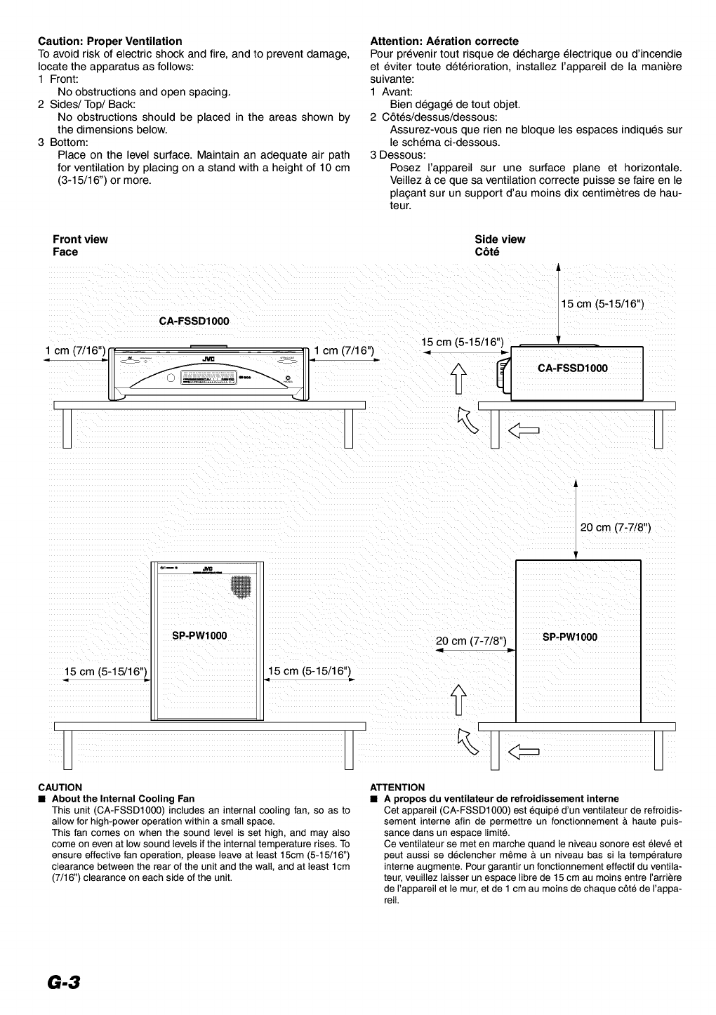
Caution: Proper Ventilation
To avoid risk of electric shock and fire, and to prevent damage,
locate the apparatus as follows:
1 Front:
No obstructions and open spacing.
2 Sides/Top/Back:
No obstructions should be placed in the areas shown by
the dimensions below.
3 Bottom:
Place on the level surface. Maintain an adequate air path
for ventilation by placing on a stand with a height of 10 cm
(3-15/16") or more.
Attention: A_ration correcte
Pour prevenir tout risque de decharge electrique ou d'incendie
et eviter toute deterioration, installez rappareil de la maniere
suivante:
1 Avant:
Bien degage de tout objet.
2 C6tes/dessus/dessous:
Assurez-vous que rien ne bloque les espaces indiques sur
le schema ci-dessous.
3 Dessous:
Posez I'appareil sur une surface plane et horizontale.
Veillez & ce que sa ventilation correcte puisse se faire en le
pla£ant sur un support d'au moins dix centimetres de hau-
teur.
Front view
Face Side view
C6t_
CA-FSSD1000
1 cm (7/16")j t = _ r_q 11
H
15 cm (5-15/16")
cm
= CA-FSSD1000
H'
SP-PWI0O0
15 cm (5-15/16")
IU
15 cm (5-15/16")
CAUTION
•About the Internal Cooling Fan
This unit (CA-FSSD1000) includes an internal cooling fan, so as to
allow for high-power operation within a small space.
This fan comes on when the sound level is set high, and may also
come on even at low sound levels if the internal temperature rises. To
ensure effective fan operation, please leave at least 15cm (5-15/16")
clearance between the rear of the unit and the wall, and at least lcm
(7/16") clearance on each side of the unit.
20 cm (7-7/8")
20 cm (7-7/8") SP-PW1 O0O
ATTENTION
•Apropos du ventilateur de refroidissement interne
Cet appareil (CA-FSSD1000) est _quipe d'un ventilateur de refroidis-
sement interne afin de permettre un fonctionnement & haute puis-
sance dans un espace limit_.
Ce ventilateur se met en marche quand le niveau sonore est _leve et
peut aussi se d_clencher m_me & un niveau bassi la temperature
interne augmente. Pour garantir un fonctionnement effectif du ventila-
teur, veuillez laisser un espace libre de 15 cm au moins entre I'arriere
de rappareil et lemur, et de 1 cm au moins de chaque c6t_ de rappa-
reil.
G-3
Thank you for purchasing the JVC Compact Component System
We hope it will be a valued addition to your home, giving you years of enjoyment
Be sure to read this instruction manual carefully before operating your new stereo system
In it you will find all the information you need to set up and use the system
If you have a query that is not answered by the manual, please contact your dealer
Features
Here are some of the things that make your System both powerful and simple to use
• The controls and operations have been redesigned to make them very easy to use, freeing you to
just enjoy the music C;.%_' .v
•With JVC's COMPU PLAY you can turn on the System and automatically start the Radio or ........
CD Player with a single touch
• The powered Subwoofer provides richness of bass in addition to faithfull reproduction at low fre
quency
• A 45 station preset capability (30 FM and 15 AM) in addition to autoseek and manual tuning
• CD options that include repeat, random and program play
• Timer functions; Daily Timer and Sleep Timer
• You can connect various external units, such as an MD recorder
• The system can play CDR and CDRW after they have been finalized
• You can play back your original CDR or CDRW recorded in Music CD format (However they may not be played back
depending on their characteristics or recording conditions.)
How This Manual Is Organized
• Basic information that is the same for many different functions eg setting the volume is given in the section
'Basic Operations', and not repeated under each function
• The names of buttons/controls and display messages are written in all capital letters: eg FM/AM, "NO DISC"
• System functions are written with an initial capital letter only: eg Normal Play
Use the table of contents to look up specific information you require
We have enjoyed making this manual for you, and hope it serves you in enjoying the many features built into your System
WARNINGS
• DO NOT PUT ANYTHING ON THE TOP COVER. IF THE SYSTEM IS OPERATED WITH SOMETHING
PUT ON THE TOP COVER, IT WILL BE DAMAGED WHEN YOU TRY TO OPEN THE TOP COVER.
•NEVER REMOVE THE TOP COVER FROM THE UNIT. SERIOUS INJURY MAY OCCUR IF THE SYS-
TEM IS OPERATED WITHOUT THE TOP COVER.
•SUPPLIED SPEAKERS (SP-FSSDIO00) ARE EXCLUSIVELY FOR THIS SYSTEM. USING WITH OTHER
DEVICES WILL DAMAGE THE SPEAKERS.
IMPORTANT CAUTIONS
1Installation of the System
• Select a place which is level, dry and neither too hot nor too cold (Between 5°C and 35°C or 41°F and 95°F)
• Leave sufficient distance between the System and a TV
• Do not use the System in a place subject to vibrations
2Power cord
• Do not handle the power cord with wet hands!
• Some power is always consumed as long as the power cord is connected to the wall outlet
• When unplugging the System from the wall outlet, always pull the plug, not the power cord
3Malfunctions, etc.
• There are no user serviceable parts inside In case of system failure, unplug the power cord and consult your dealer
• Do not insert any metallic object into the System
• Do not insert your hand between the Top Cover and the main body when the Top Cover is being closed
1
Introduction ........................................................................................................ 1
Features ...................................................................................................................................... 1
How This Manual is Organized ................................................................................................. 1
WARNINGS .............................................................................................................................. 1
IMPORTANT CAUTIONS ....................................................................................................... 1
Getting Started ................................................................................................... 3
Accessories ................................................................................................................................. 3
How To Put Batteries in the Remote Control ............................................................................ 3
Using the Remote Control .......................................................................................................... 3
Connecting the FM Antenna ...................................................................................................... 4
Connecting the AM Antenna ...................................................................................................... 5
Connecting the Speakers (SP-FSSD 1000) ................................................................................. 6
Connecting the Powered Subwoofer (SP-PW 1000) ................................................................... 7
Attaching the Spacers ................................................................................................................. 7
Connecting External Equipment ................................................................................................ 7
Connecting an MD Recorder, etc (Digital Output) .................................................................... 7
Connecting the AC Power Cord ................................................................................................. 8
COMPU Play .............................................................................................................................. 8
Automatic Power On .................................................................................................................. 8
Basic Operations ............................................................................................... 9
Turning the Power On and Off ................................................................................................... 9
Adjusting the Brightness (DIMMER) ........................................................................................ 9
Adjusting the Volume ................................................................................................................ 9
Fade-out Muting (FADE MUTING) ........................................................................................ 10
Tone Control (BASS/TREBLE) ............................................................................................... 10
Showing the Time (CLOCK/DISPLAY) ................................................................................. 10
Sliding the Top Cover (DOOR SLIDE) ................................................................................... 10
Using the Powered Subwoofer ....................................................................... 11
Operating the Powered Subwoofer .......................................................................................... 11
Using the Tuner ................................................................................................ 12
Tuning in a Station ................................................................................................................... 12
Presetting Stations .................................................................................................................... 13
Auto Presetting ......................................................................................................................... 13
To Change the FM Reception Mode ........................................................................................ 13
Using the CD Player ......................................................................................... 14
To insert a CD .......................................................................................................................... 14
To Unload a CD ....................................................................................................................... 15
Basics of Using the CD Player-Normal Play ........................................................................... 15
Programming the Playing Order of the Tracks ........................................................................ 15
Random Play ............................................................................................................................ 16
Repeating Tracks ...................................................................................................................... 16
Using External Equipments ............................................................................ 17
Listening to External Equipment .............................................................................................. 17
Recording the System's Source to External Equipment .......................................................... 17
Using the Timers .............................................................................................. 18
Setting the Clock ...................................................................................................................... 18
Setting the Daily Timer ............................................................................................................ 18
Setting the SLEEP Timer ......................................................................................................... 20
Care And Maintenance .................................................................................... 21
Troubleshooting ............................................................................................... 22
Specifications ................................................................................................... 23
2
Accessories
Make sure that you have all of the following items, which are supplied with the System.
Power Cord (1)
AM Loop Antenna (1)
Remote Control (1)
Batteries (2)
FM Wire Antenna (1)
Signal Cord (1)
Spacers (4) (For SP-PW1000)
If any of these items are missing, contact your dealer immediately.
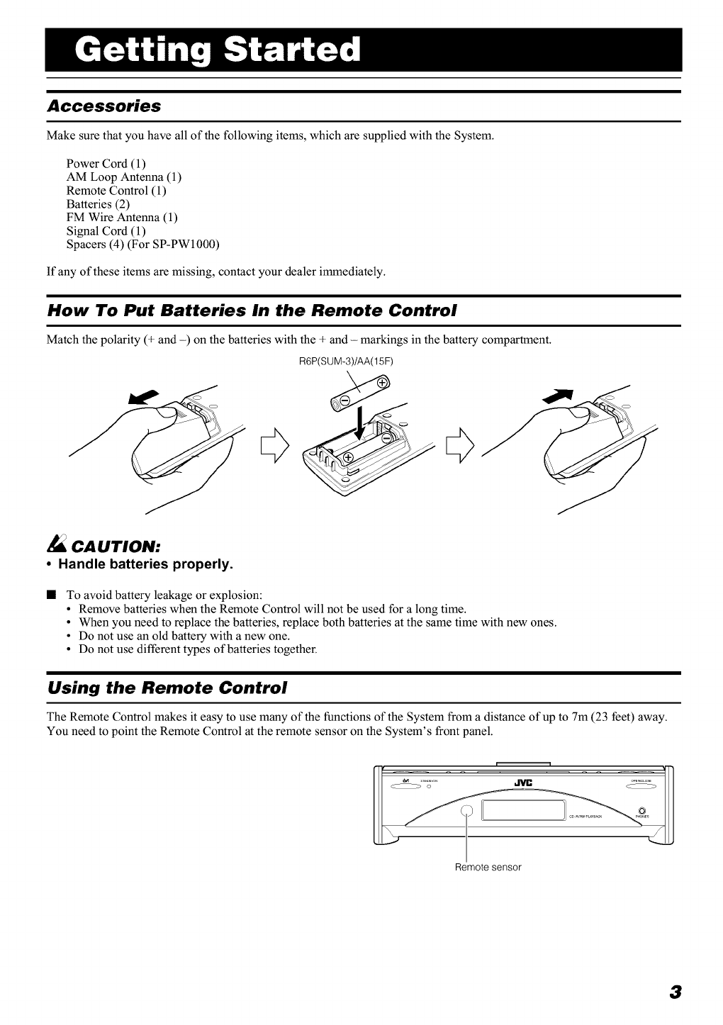
How To Put Batteries In the Remote Control
Match the polarity (+ and -) on the batteries with the + and - markings in the battery compartment.
R6P(SUM-3)/AA(15F)
CA UTION:
• Handle batteries properly.
To avoid battery leakage or explosion:
•Remove batteries when the Remote Control will not be used for a long time.
• When you need to replace the batteries, replace both batteries at the same time with new ones.
• Do not use an old battery with a new one.
• Do not use different types of batteries together.
Using the Remote Control
The Remote Control makes it easy to use many of the functions of the System from a distance of up to 7m (23 feet) away.
You need to point the Remote Control at the remote sensor on the System's front panel.
Remote sensor
3
Getting Started
CA UTION:
• Make all connections before plugging the System into an AC power outlet.
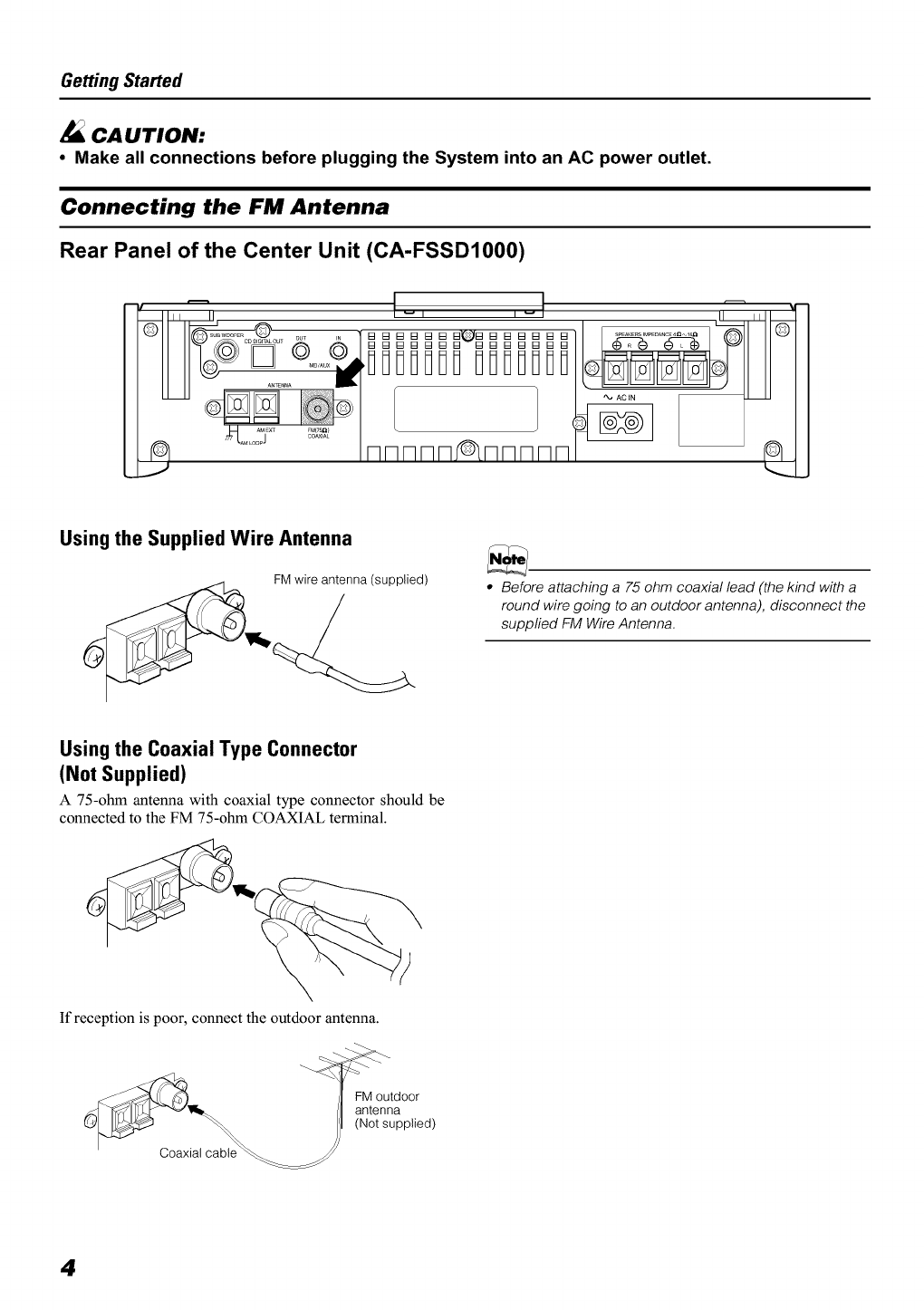
Connecting the FM Antenna
Rear Panel of the Center Unit (CA-FSSD1000)
II _ w I I w
out ,, "1 [] [] [] [] [] [] []'(,_[] [] [] [] [] [] []
_°_'Q Q/[][]•[][] iiiiiiiii
t_, AC IN
©
Using the Supplied Wire Antenna
FM wire antenna (supplied) •Before attaching a 75 ohm coaxial lead (the kind with a
round wire going to an outdoor antenna), disconnect the
supplied FM Wire Antenna.
Using the Coaxial Type Connector
(Not Supplied)
A 75-ohm antenna with coaxial type connector should be
connected to the FM 75-ohm COAXIAL terminal.
If reception is poor, connect the outdoor antenna.
Coaxial cable
4
Getting Started
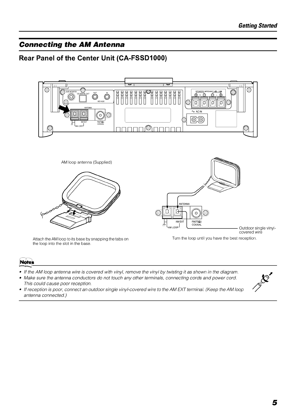
Connecting the AM Antenna
Rear Panel of the Center Unit (CA-FSSDIO00)
w w
nnnnn nnnnn
AM loop antenna (Supplied)
Attach the AM loop to its base by snapping the tabs on
the loop into the slot in the base.
AMjEXT FM(75_)
COAXIAL
AM LOOP Outdoor single vinyl-
covered wire
Turn the loop until you have the best reception.
•If the AM loop antenna wire is covered with vinyl, remove the vinyl by twisting it as shown in the diagram.
•Make sure the antenna conductors do not touch any other terminals, connecting cords and power cord.
This could cause poor reception.
• If reception is poor, connect an outdoor single vinyl-covered wire to the AM EXT terminal (Keep the AM loop
antenna connected.)
5
Getting Started
CA UTION:
• Make all connections before plugging the System into an AC power outlet.
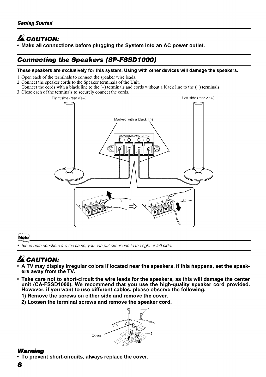
Connecting the Speakers (SP.FSSDIO00)
These speakers are exclusively for this system. Using with other devices will damege the speakers.
1. Open each of the terminals to connect the speaker wire leads.
2. Connect the speaker cords to the Speaker terminals of the Unit.
Connect the cords with a black line to the (-) terminals and cords without a black line to the (+) terminals.
3. Close each of the terminals to securely connect the cords.
Right side (rear view) Left side (rear view)
Marked with a black line
SPEAKERSIMPEDANCE4n_I6Q
•Since both speakers are the same, you can put either one to the right or left side.
CA UTION:
•ATV may display irregular colors if located near the speakers. If this happens, set the speak-
ers away from the TV.
•Take care not to short-circuit the wire leads for the speakers, as this will damage the center
unit (CA-FSSD1000). We recommend that you use the high-quality speaker cord provided.
However, if you want to use different cables, please observe the following.
1) Remove the screws on either side and remove the cover.
2) Loosen the terminal screws and remove the speaker cord.
Cover
Warning
• To prevent short-circuits, always replace the cover.
6
Getting Started
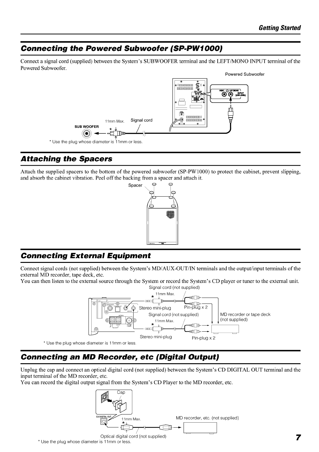
Connecting the Powered Subwoofer (SP.PWIO00)
Connect a signal cord (supplied) between the System's SUBWOOFER terminal and the LEFT_ONO INPUT terminal of the
Powered Subwoofer.
Powered Subwoofer
1lmm Max. Signal cord
SUB WOOFER "k ,L. /
* Use the plug whose diameter is 1lmm or less.
Attaching the Spacers
Attach the supplied spacers to the bottom of the powered subwoofer (SP-PW1000) to protect the cabinet, prevent slipping,
and absorb the cabinet vibration. Peel off the backing from a spacer and attach it.
Spacer \ o
Connecting External Equipment
Connect signal cords (not supplied) between the System's MD/AUX-OUT/IN terminals and the output/input terminals of the
external MD recorder, tape deck, etc.
You can then listen to the external source through the System or record the System's CD player or tuner to the external unit.
Signal cord (not supplied)
11mm Max. //.--,.mm_=
I-_,,,.... ___l _
i__,@_Stereo mini-plug _x2-- I I
I _ ,...... I Signal cord (not supplied) I I MD recorder or tape deck
I11m_ Max. /I 1(not supplied)
Stereo mini-plug Pin-plug x 2
* Use the plug whose diameter is 1lmm or less.
Connecting an MD Recorder, etc (Digital Output)
Unplug the cap and connect an optical digital cord (not supplied) between the System's CD DIGITAL OUT terminal and the
input terminal of the MD recorder, etc.
You can record the digital output signal from the System's CD Player to the MD recorder, etc.
°°_"J/_lmmMax
/r,;
Optical digital cord (not supplied)
* Use the plug whose diameter is 1lmm or less.
MD recorder, etc. (not supplied)
7
Getting Started
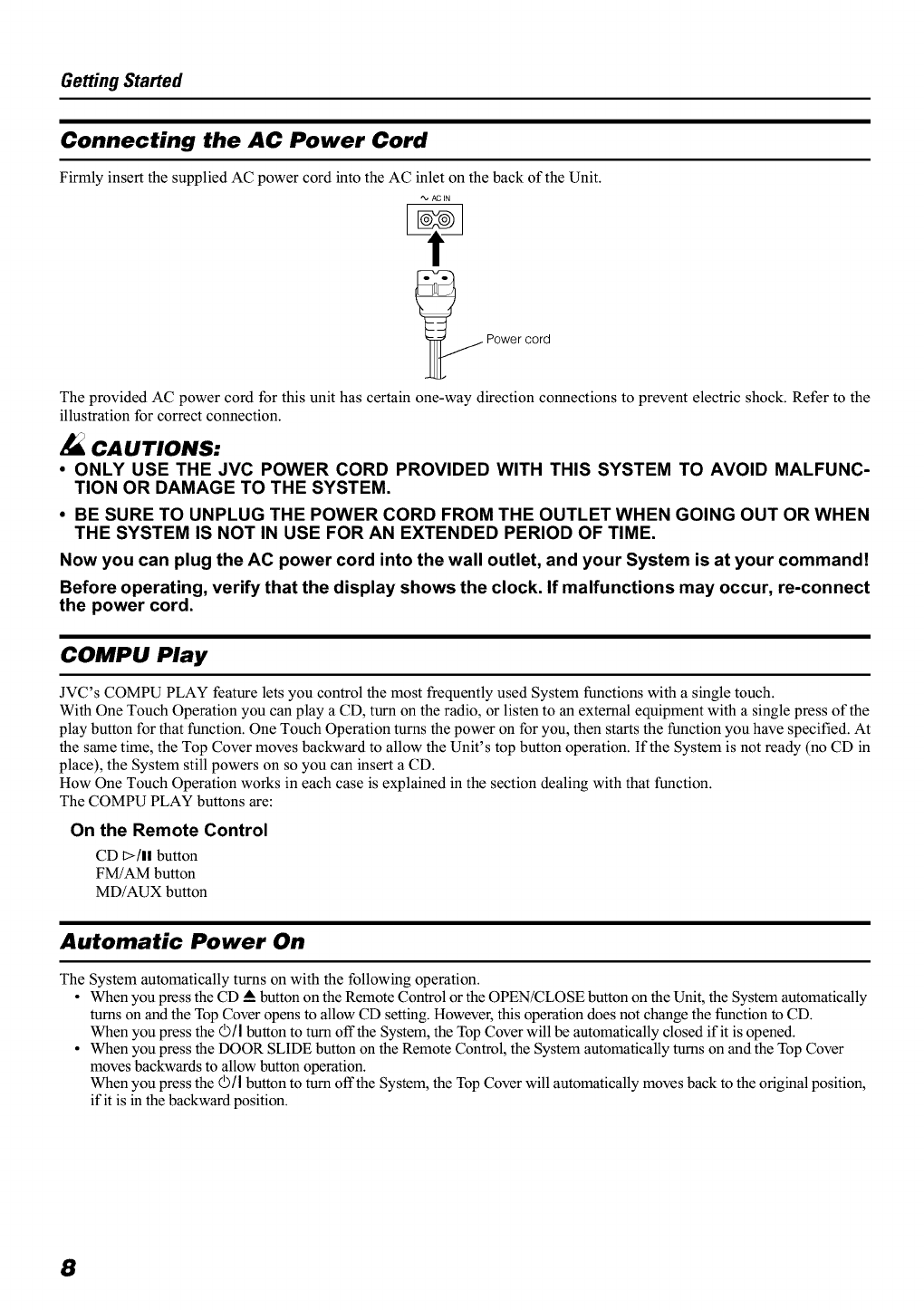
Connecting the AC Power Cord
Firmly insert the supplied AC power cord into the AC inlet on the back of the Unit.
"_, AC IN
_ Power cord
The provided AC power cord for this unit has certain one-way direction connections to prevent electric shock. Refer to the
illustration for correct connection.
CAUTIONS:
• ONLY USE THE JVC POWER CORD PROVIDED WITH THIS SYSTEM TO AVOID MALFUNC-
TION OR DAMAGE TO THE SYSTEM.
•BE SURE TO UNPLUG THE POWER CORD FROM THE OUTLET WHEN GOING OUT OR WHEN
THE SYSTEM IS NOT IN USE FOR AN EXTENDED PERIOD OF TIME.
Now you can plug the AC power cord into the wall outlet, and your System is at your command!
Before operating, verify that the display shows the clock. If malfunctions may occur, re-connect
the power cord.
COMPU Play
JVC's COMPU PLAY feature lets you control the most frequently used System functions with a single touch.
With One Touch Operation you can play a CD, turn on the radio, or listen to an external equipment with a single press of the
play button for that function. One Touch Operation turns the power on for you, then starts the function you have specified. At
the same time, the Top Cover moves backward to allow the Unit's top button operation. If the System is not ready (no CD in
place), the System still powers on so you can insert a CD.
How One Touch Operation works in each case is explained in the section dealing with that function.
The COMPU PLAY buttons are:
On the Remote Control
CD t>/ll button
FM/AM button
MD/AUX button
Automatic Power On
The System automatically turns on with the following operation.
•When you press the CD _Abutton on the Remote Control or the 0PEN/CLOSE button on the Unit, the System automatically
turns on and the Top Cover opens to allow CD setting. However, this operation does not change the function to CD.
When you press the ©/I button to turn off the System, the Top Cover will be automatically closed if it is opened.
• When you press the DOOR SLIDE button on the Remote Control, the System automatically turns on and the Top Cover
moves backwards to allow button operation.
When you press the ©/I button to turn offthe System, the Top Cover will automatically moves back to the original position,
if it is in the backward position.
8
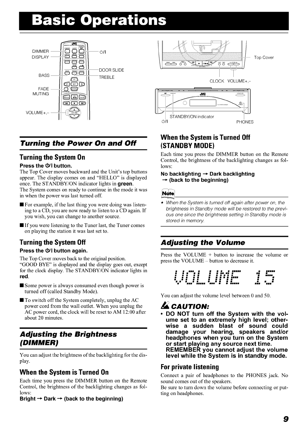
DIMMER _©/I
I DOOR SLIDE
TREBLE
FADE
MUTING
VOLUME+,-
Top Cover
CLOCK VOLUME+,-
©/I PHONES
Turning the Power On and Off
Turning the System On
Press the r_/I button.
The Top Cover moves backward and the Unit's top buttons
appear. The display comes on and "HELLO" is displayed
once. The STANDBY/ON indicator lights in green.
The System comes on ready to continue in the mode it was
in when the power was last turned off.
• For example, if the last thing you were doing was listen-
ing to a CD, you are now ready to listen to a CD again. If
you wish, you can change to another source.
• If you were listening to the Tuner last, the Tuner comes
on playing the station it was last set to.
Turning the System Off
Press the r_/I button again.
The Top Cover moves back to the original position.
"GOOD BYE" is displayed and the display goes out, except
for the clock display. The STANDBY/ON indicator lights in
red.
• Some power is always consumed even though power is
turned off (called Standby Mode).
• To switch off the System completely, unplug the AC
power cord from the wall outlet. When you unplug the
AC power cord, the clock will be reset to AM 12:00 after
about 20 minutes.
Adjusting the Brightness
(DIMMER)
You can adjust the brightness of the backlighting for the dis-
play.
When the System is Turned On
Each time you press the DIMMER button on the Remote
Control, the brightness of the backlighting changes as fol-
lows:
Bright --_ Dark --_ (back to the beginning)
When the System is Turned Off
(STANDBY MODE)
Each time you press the DIMMER button on the Remote
Control, the brightness of the backlighting changes as fol-
lows:
No backlighting --_Dark backlighting
--_ (back to the beginning)
•Whenthe System is turned off again after power on, the
brightness in Standby mode will be restored to the previ-
ous one since the brightness setting in Standby mode is
stored in memory.
Adjusting the Volume
Press the VOLUME + button to increase the volume or
press the VOLUME - button to decrease it.
: : ,,; :: :;..:: ..... :....
•t.:: :" :::':-"- 1D
",,," :,,,, ".,," ; ; ;,,,,
You can adjust the volume level between 0 and 50.
Z_ CAUTION:
•DO NOT turn off the System with the vol-
ume set to an extremely high level; other-
wise a sudden blast of sound could
damage your hearing, speakers and/or
headphones when you turn on the System
or start playing any source next time,
REMEMBER you cannot adjust the volume
level while the System is in standby mode,
For private listening
Connect a pair of headphones to the PHONES jack. No
sound comes out of the speakers.
Be sure to turn down the volume before connecting or put-
ting on headphones.
9
Basic Operations
Fade.out Muting (FADE MUTING)
You can mute the output with one touch operation.
To mute the output, press the FADE MUTING button
on the Remote Control. Then, the output will be faded out
and becomes 0.
To release muting, press the FADE MUT1NG button once
again. Then, the output will be faded in to the original level.
Tone Control (BASS/TREBLE)
You can control the tone by changing the bass and treble.
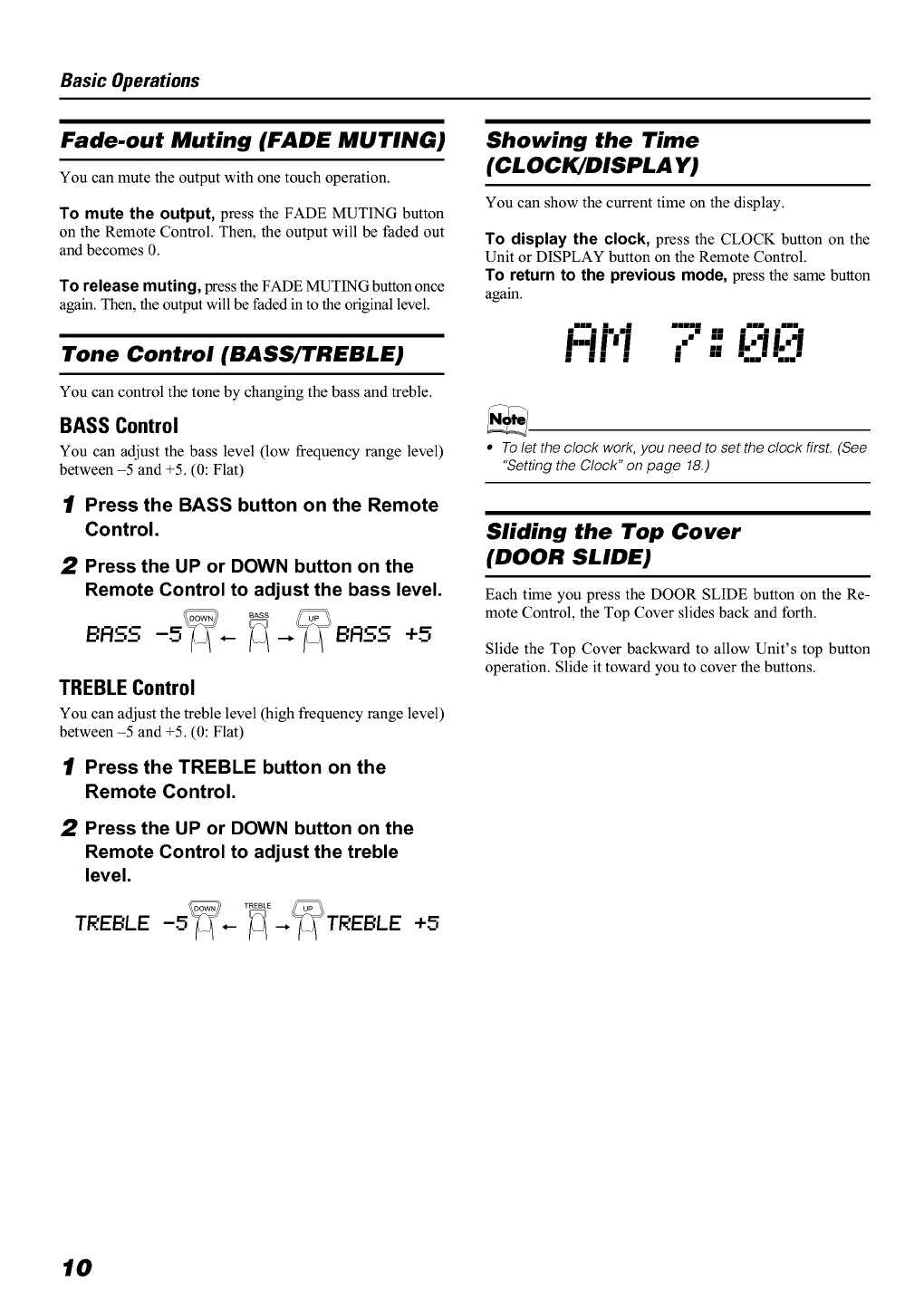
BASS Control
You can adjust the bass level (low frequency range level)
between -5 and +5. (0: Flat)
1Press the BASS button on the Remote
Control.
2Press the UP or DOWN button on the
Remote Control to adjust the bass level.
BASS -5 ,-- +5
TREBLEControl
You can adjust the treble level (high frequency range level)
between -5 and +5. (0: Flat)
1Press the TREBLE button on the
Remote Control.
2Press the UP or DOWN button on the
Remote Control to adjust the treble
level.
TREBLE' -5_,-_--,_TREBLE' +5
Showing the Time
(CLOCK/DISPLAY)
You can show the current time on the display.
To display the clock, press the CLOCK button on the
Unit or DISPLAY button on the Remote Control.
To return to the previous mode, press the same button
again.
."% |. ,| ----| ,, ,"% .--%
I'll'l ," .."E:'!E:'!
| | | • --
•To let the clock work,you need to set the clock first. (See
"Setting the Clock" on page 18.)
Sliding the Top Cover
(DOOR SLIDE)
Each time you press the DOOR SLIDE button on the Re-
mote Control, the Top Cover slides back and forth.
Slide the Top Cover backward to allow Unit's top button
operation. Slide it toward you to cover the buttons.
10
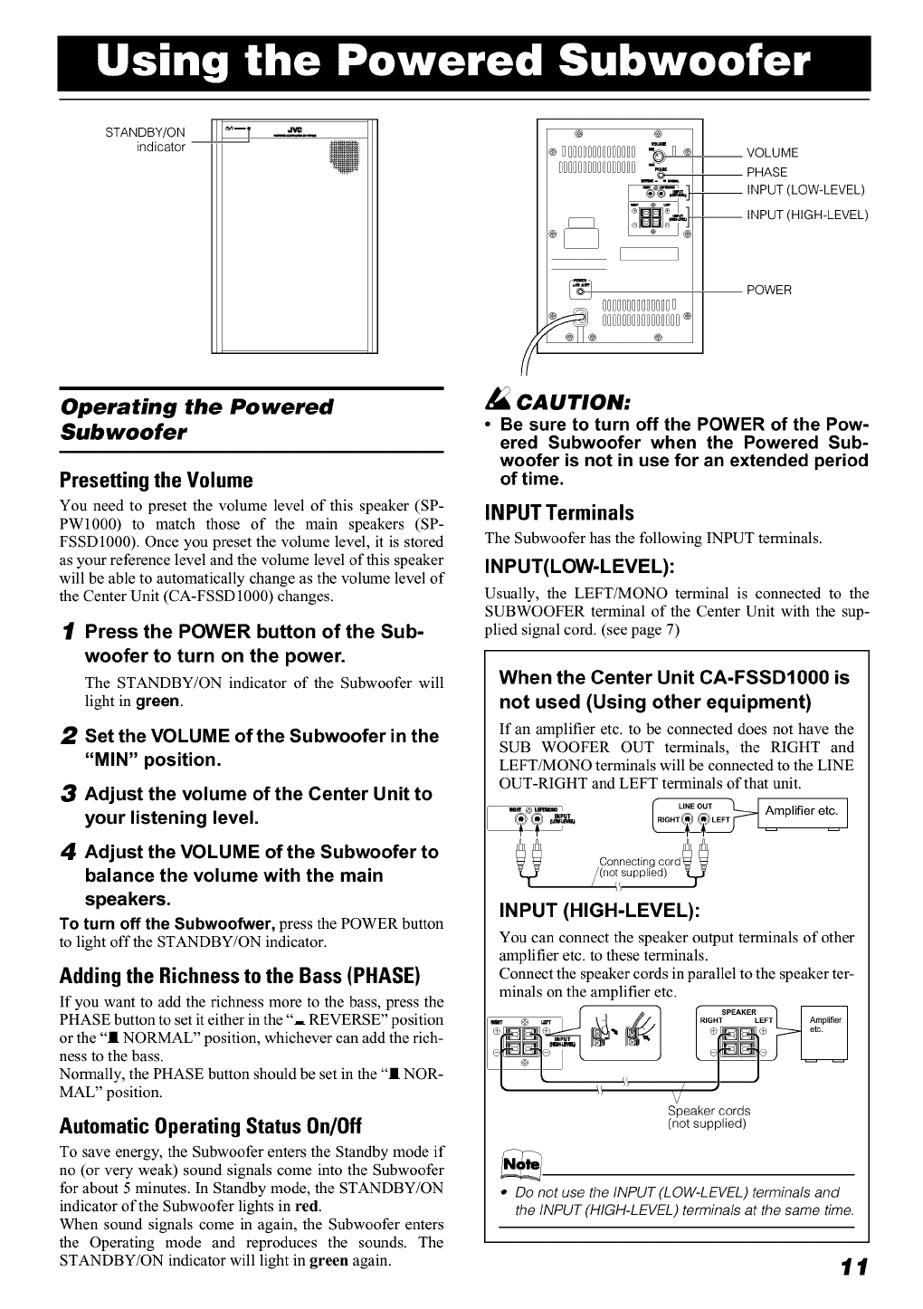
STANOBY/ONIII '--T
indicator --
Operating the Powered
Subwoofer
Presetting the Volume
You need to preset the volume level of this speaker (SP-
PWl000) to match those of the main speakers (SP-
FSSD1000). Once you preset the volume level, it is stored
as your reference level and the volume level of this speaker
will be able to automatically change as the volume level of
the Center Unit (CA-FSSD 1000) changes.
1Press the POWER button of the Sub-
woofer to turn on the power.
The STANDBY/ON indicator of the Subwoofer will
light in green.
2Set the VOLUME of the Subwoofer in the
"MIN" position.
3Adjust the volume of the Center Unit to
your listening level.
4Adjust the VOLUME of the Subwoofer to
balance the volume with the main
speakers.
To turn off the Subwoofwer, press the POWER button
to light off the STANDBY/ON indicator.
Adding the Richness to the Bass (PHASE)
If you want to add the richness more to the bass, press the
PHASE button to set it either in the "-- REVERSE" position
or the "11NORMAL" position, whichever can add the rich-
ness to the bass.
Normally, the PHASE button should be set in the "11 NOR-
MAL" position.
Automatic Operating Status On/Off
To save energy, the Subwoofer enters the Standby mode if
no (or very weak) sound signals come into the Subwoofer
for about 5 minutes. In Standby mode, the STANDBY/ON
indicator of the Subwoofer lights in red.
When sound signals come in again, the Subwoofer enters
the Operating mode and reproduces the sounds. The
STANDBY/ON indicator will light in green again.
® 000000000000000"_ o
oooooooooooooooo-- II
%
CAUTION:
VOLUME
PHASE
__ INPUT (LOW-LEVEL)
INPUT (HIGH-LEVEL)
POWER
•Be sure to turn off the POWER of the Pow-
ered Subwoofer when the Powered Sub-
woofer is not in use for an extended period
of time,
INPUT Terminals
The Subwoofer has the following INPUT terminals.
INPUT(LOW-LEVEL):
Usually, the LEFT/MONO terminal is connected to the
SUBWOOFER terminal of the Center Unit with the sup-
plied signal cord. (see page 7)
When the Center Unit CA-FSSDIO00 is
not used (Using other equipment)
If an amplifier etc. to be connected does not have the
SUB WOOFER OUT terminals, the RIGHT and
LEFT/MONO terminals will be connected to the LINE
OUT-RIGHT and LEFT terminals of that unit.
_(_ R_G_mu(_i_ Amplifier etc.
Connecting cord _0
/(n°i,supplied) _FJ_
INPUT (HIGH-LEVEL):
You can connect the speaker output terminals of other
amplifier etc. to these terminals.
Connect the speaker cords in parallel to the speaker ter-
minals on the amplifier etc.
l/ /
Speaker cords
(not supplied)
•Do not use the INPUT (LOW-LEVEL) terminals and
the INPUT (HIGH-LEVEL) terminals at the same time.
11
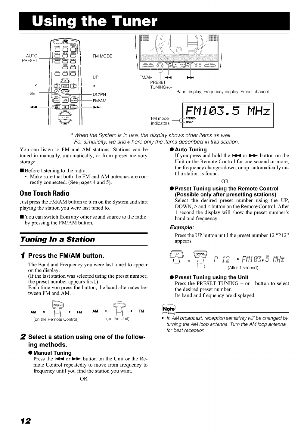
AUTO
PRESET
UP
DOWN
PRESET
TUNING+,- Band display, Frequency display, Preset channel
FM mode
indicators
I
I. ii
I t,11 r'!Hz
*When the System is in use, the display shows other items as well.
For simplicity, we show here only the items described in this section.
You can listen to FM and AM stations. Stations can be
tuned in manually, automatically, or from preset memory
storage.
• Before listening to the radio:
• Make sure that both the FM and AM antennas are cor-
rectly connected. (See pages 4 and 5).
OneTouch Radio
Just press the FM/AM button to turn on the System and start
playing the station you were last tuned to.
• You can switch from any other sound source to the radio
by pressing the FM/AM button.
Tuning In a Station
•Auto Tuning
If you press and hold the _ or I,€,,t button on the
Unit or the Remote Control for one second or more,
the frequency changes down, or up, automatically un-
til a station is found.
OR
• Preset Tuning using the Remote Control
(Possible only after presetting stations)
Select the desired preset number using the UP,
DOWN, > and < button on the Remote Control. After
1 second the display will show the preset number's
band and frequency.
Example:
Press the UP button until the preset number 12 "P12"
appears.
1[ Press the FM/AM button.
The Band and Frequency you were last tuned to appear
on the display.
(If the last station was selected using the preset number,
the preset number appears first.)
Each time you press the button, the band alternates be-
tween FM and AM.
rM/A_AM _ _ FM AM 4.-- "--_ FM
(on the Remote Control) (on the Unit)
2Select a station using one of the follow-
ing methods.
•Manual Tuning
Press the _ or I,€,,t button on the Unit or the Re-
mote Control repeatedly to move from frequency to
frequency until you find the station you want.
OR
(After 1 second)
•Preset Tuning using the Unit
Press the PRESET TUNING + or - button to select
the desired preset number.
Its band and frequency are displayed.
•In AM broadcast, reception sensitivity will be changed by
turning the AM loop antenna. Turn the AM loop antenna
for best reception.
12

Using the Tuner
Presetting Stations
You can preset up to 30 FM stations and up to 15 AM sta-
tions using the Remote Control.
•Preset numbers may have been set to factory test fre-
quencies prior to shipmenL This is not a malfunction. You
can preset the stations you want into memory by following
one of the presetting methods below.
Auto Presetting
In each band, you can automatically preset FM-30, AM-15
stations. Preset numbers will be allocated as stations are
found, starting from the lowest frequency and moving up
the frequency.
AUTO
_ _T (for 2 seconds)
Manual Presetting
/1\
FM = 30, AM = 15
_TO_E¢
/I \
1Select a band by pressing the FM/AM
button.
2Press the I<< or _button to tune in a
station.
3Press the SET button.
"SET" will blink for 5 seconds.
Within 5 seconds, proceed to the next step.
When the display returns to the one set in step 2 after 5
seconds, press the SET button again.
4Press the UP, DOWN, >, or < button
within 5 seconds to select the preset
number.
UP or DOWN button:Increase or decrease the preset
number by 1.
Pressing and holding the button
will continuously increase or de-
crease the preset number.
> or < button: Increase or decrease the preset
number by 1.
Pressing and holding the button
will rapidly increase or decrease
the preset number.
5Press the SET button within 5 seconds.
"STORED" appears and after 2 seconds, the display re-
turns to the broadcast frequency display.
6Repeat above steps 1 to 5 for each sta-
tion you want to store in memory with a
preset number,
To change the preset stations, repeatthe same
steps as above.
1Select a band by pressing the FM/AM
button.
2Press the AUTO PRESET button on the
Remote Control for more than two sec-
onds,
3Repeat steps 1-2 for the other band.
• If you want to change the preset stations, carry out the
Manual Presetting for the desired preset numbers.
Z_ CAUTION:
•Even if the system is unplugged or if the
power failure occurs, the preset stations
will be stored for about 24 hours, However,
in case the preset stations are erased, you
will need to preset the stations again,
To Change the FM
Reception Mode
When you are tuned into an FM stereo broadcast, the
"STEREO" indicator lights up and you can hear stereo ef-
fects.
If an FM stereo broadcast is hard to receive or noisy, you
can select Monaural mode. Reception improves, but you
lose stereo effect.
Press the FM MODE button on the Remote Control
so that the "MONO" indicator lights up on the dis-
play.
FM MODE
--_ MONO
To restore the stereo effect, press the FM MODE button
on the Remote Control so that the "MONO" indicator goes off.
13
REPEAT
CD
CANCEL
UP
>
DOWN
Cover
I_14 •CD _/uu
OPEN/CLOSE
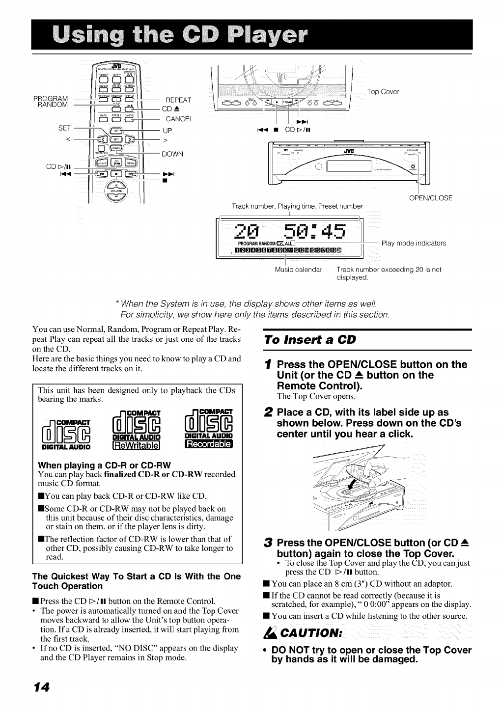
Track number, Playing time, Preset number
I
4._'3 '1
PROGRAMRANDOM_ALL_ _" Play mode indicators
,ilm_llll_ll_DI]Dmm_mmmmr_mmm,
IJ
Music calendar Track number exceeding 20 is not
displayed,
* When the System is in use, the display shows other items as well.
For simplicity, we show here only the items described in this section.
You can use Normal, Random, Program or Repeat Play. Re-
peat Play can repeat all the tracks or just one of the tracks
on the CD.
Here are the basic things you need to know to play a CD and
locate the different tracks on it.
This unit has been designed only to playback the CDs
bearing the marks.
DIGITALAUDIO IReWritablel
When playing a CD-R or CD-RW
You can play back finalized CD-R or CD-RW recorded
music CD format.
IYou can play back CD-R or CD-RW like CD.
ISome CD-R or CD-RW may not be played back on
this unit because of their disc characteristics, damage
or stain on them, or if the player lens is dirty.
IThe reflection factor of CD-RW is lower than that of
other CD, possibly causing CD-RW to take longer to
read.
The Quickest Way To Start a CD Is With the One
Touch Operation
• Press the CD t>/ll button on the Remote Control.
•The power is automatically turned on and the Top Cover
moves backward to allow the Unit's top button opera-
tion. If a CD is already inserted, it will start playing from
the first track.
• If no CD is inserted, "NO DISC" appears on the display
and the CD Player remains in Stop mode.
To Insert a CD
1Press the OPEN/CLOSE button on the
Unit (or the CD __ button on the
Remote Control),
The Top Cover opens.
2Place a CD, with its label side up as
shown below. Press down on the CD's
center until you hear a click.
3Press the OPEN/CLOSE button (or CD A
button) again to close the Top Cover.
• To close the Top Cover and play the CD, you can just
press the CD [>/ll button.
• You can place an 8 cm (3") CD without an adaptor.
• If the CD cannot be read correctly (because it is
scratched, for example)," 0 0:00" appears on the display.
• You can insert a CD while listening to the other source.
•DO NOT try to open or close the Top Cover
by hands as it will be damaged.
14
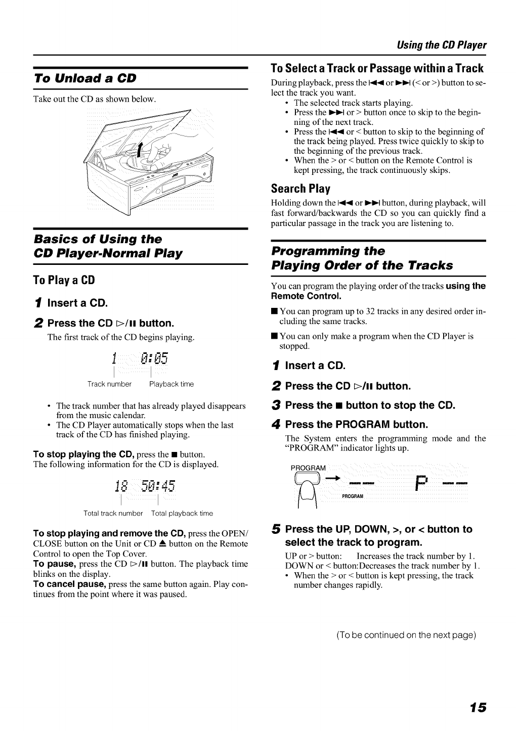
To Unload a CD
Take out the CD as shown below.
Basics of Using the
CD Player.Normal Play
To Play a CD
1Insert a CD.
2Press the CD E>/li button.
The first track of the CD begins playing.
i-:-5
[ [
Track number Playback time
Using the CD Player
To Select a Track or Passage within a Track
During playback, press the _ or _ (< or >) button to se-
lect the track you want.
•The selected track starts playing.
• Press the _ or > button once to skip to the begin-
ning of the next track.
• Press the _ or < button to skip to the beginning of
the track being played. Press twice quickly to skip to
the beginning of the previous track.
• When the > or < button on the Remote Control is
kept pressing, the track continuously skips.
Search Play
Holding down the _ or _ button, during playback, will
fast forward/backwards the CD so you can quickly find a
particular passage in the track you are listening to.
•The track number that has already played disappears
from the music calendar.
• The CD Player automatically stops when the last
track of the CD has finished playing.
To stop playing the CD, press the •button.
The following information for the CD is displayed.
_..=. ---.- .- ...-.--
""..: ".J':." : "T'._
/ iiiiiiiiiiiiiiiii
Total track number Total playback time
To stop playing and remove the CD, press the OPEN/
CLOSE button on the Unit or CD • button on the Remote
Control to open the Top Cover.
TO pause, press the CD t>/ll button. The playback time
blinks on the display.
TO cancel pause, press the same button again. Play con-
tinues from the point where it was paused.
Programming the
Playing Order of the Tracks
You can program the playing order of the tracks using the
Remote Control.
•You can program up to 32 tracks in any desired order in-
cluding the same tracks.
• You can only make a program when the CD Player is
stopped.
1Insert a CD.
2Press the CD E>/li button.
3Press the •button to stop the CD.
4Press the PROGRAM button.
The System enters the programming mode and the
"PROGRAM" indicator lights up.
PROGRAM
5Press the UP, DOWN, >, or < button to
select the track to program.
UP or > button: Increases the track number by 1.
DOWN or < button:Decreases the track number by 1.
• When the > or < button is kept pressing, the track
number changes rapidly.
(To be continued on the next page)
15
Using the CD Player
Random Play
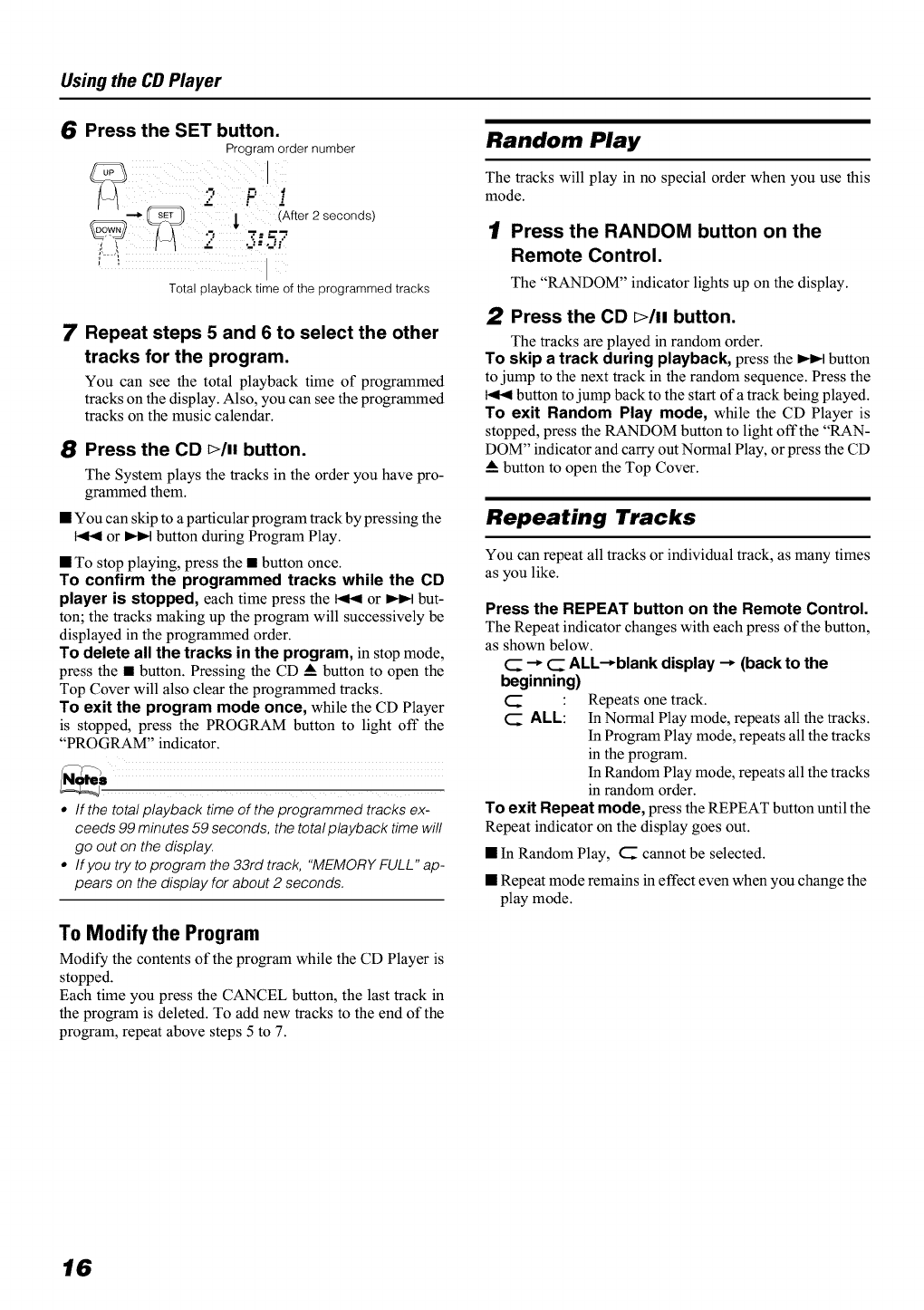
6Press the SET button.
Program order number
i
__ 2 _ _i_ After 2 secOnds)
Total playback time of the programmed tracks
7Repeat steps 5 and 6 to select the other
tracks for the program.
You can see the total playback time of programmed
tracks on the display. Also, you can see the programmed
tracks on the music calendar.
8Press the CD Plumbutton.
The System plays the tracks in the order you have pro-
grammed them.
• You can skip to a particular program track by pressing the
or _ button during Program Play.
• To stop playing, press the • button once.
To confirm the programmed tracks while the CD
player is stopped, each time press the _ or _ but-
ton; the tracks making up the program will successively be
displayed in the programmed order.
To delete all the tracks in the program, in stop mode,
press the • button. Pressing the CD _Abutton to open the
Top Cover will also clear the programmed tracks.
To exit the program mode once, while the CD Player
is stopped, press the PROGRAM button to light oft" the
"PROGRAM" indicator.
•If the total playback time of the programmed tracks ex-
ceeds 99 minutes 59 seconds, the total playback time will
go out on the display.
• If you try to program the 33rd track, "MEMORY FULL" ap-
pears on the display for about 2 seconds.
To Modify the Program
Modify the contents of the program while the CD Player is
stopped.
Each time you press the CANCEL button, the last track in
the program is deleted. To add new tracks to the end of the
program, repeat above steps 5 to 7.
The tracks will play in no special order when you use this
mode.
1[ Press the RANDOM button on the
Remote Control.
The "RANDOM" indicator lights up on the display.
2Press the CD DIll button.
The tracks are played in random order.
To skip a track during playback, press the _ button
to jump to the next track in the random sequence. Press the
button to jump back to the start of a track being played.
To exit Random Play mode, while the CD Player is
stopped, press the RANDOM button to light oft"the "RAN-
DOM" indicator and carry out Normal Play, or press the CD
_Abutton to open the Top Cover.
Repeating Tracks
You can repeat all tracks or individual track, as many times
as you like.
Press the REPEAT button on the Remote Control.
The Repeat indicator changes with each press of the button,
as shown below.
(_ --_ <_ ALL-_blank display --_ (back to the
beginning)
CALL: Repeats one track.
In Normal Play mode, repeats all the tracks.
In Program Play mode, repeats all the tracks
in the program.
In Random Play mode, repeats all the tracks
in random order.
To exit Repeat mode, press the REPEAT button until the
Repeat indicator on the display goes out.
• In Random Play, C cannot be selected.
• Repeat mode remains in effect even when you change the
play mode.
16
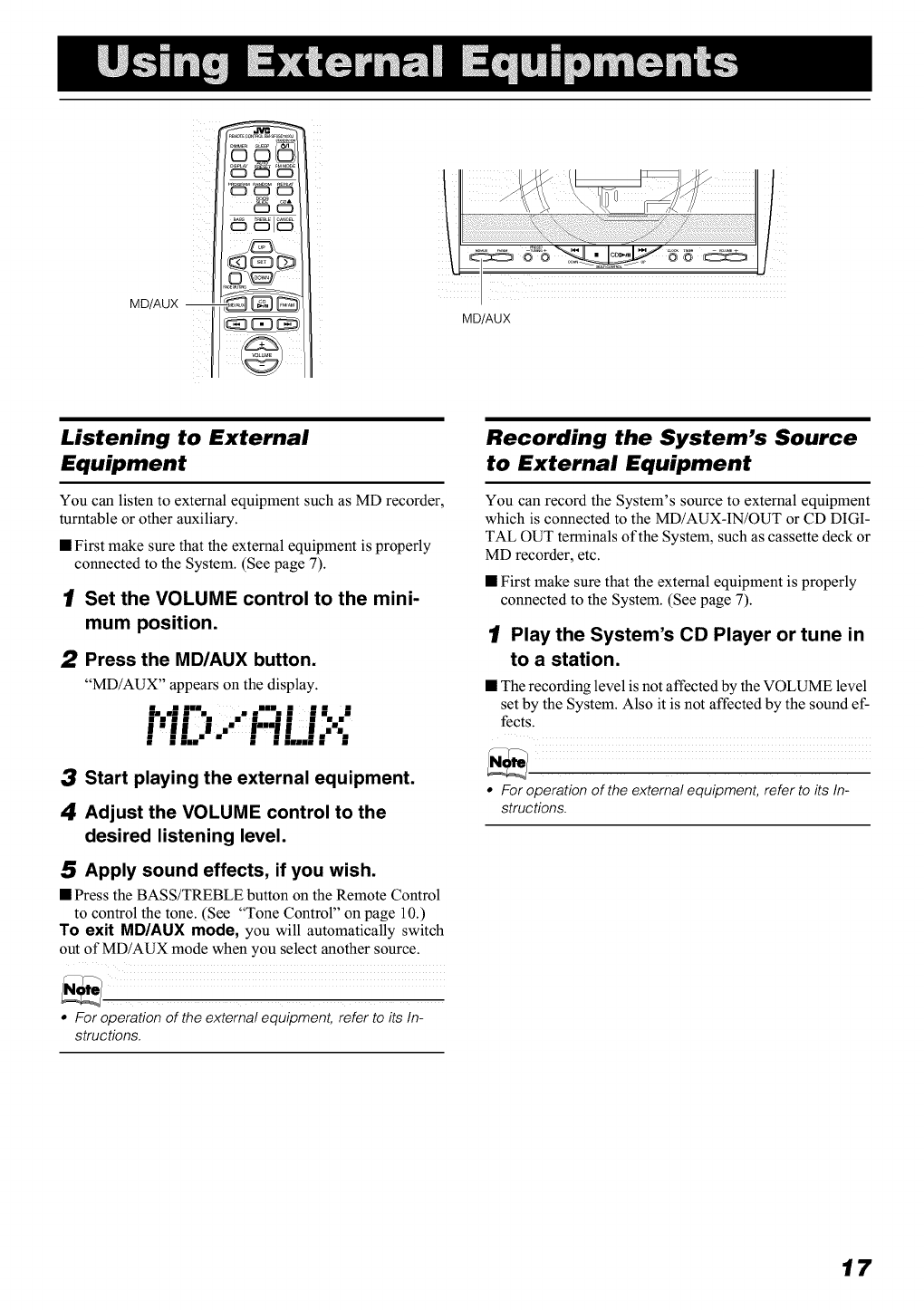
MD/AUX --
_1_
d_:_3c_ 0_3
Listening to External
Equipment
You can listen to external equipment such as MD recorder,
turntable or other auxiliary.
• First make sure that the external equipment is properly
connected to the System. (See page 7).
1Set the VOLUME control to the mini-
mum position.
2Press the MD/AUX button.
"MD/AUX" appears on the display.
I.,;|'% ..";-" |; |
i'i iJ ." i'i Li ,:':,
3Start playing the external equipment.
4Adjust the VOLUME control to the
desired listening level.
5Apply sound effects, if you wish.
• Press the BASS/TREBLE button on the Remote Control
to control the tone. (See "Tone Control" on page 10.)
TO exit MD/AUX mode, you will automatically switch
out of MD/AUX mode when you select another source.
•For operation of the external equipment, refer to its In-
structions.
Recording the System's Source
to External Equipment
You can record the System's source to external equipment
which is connected to the MD/AUX-IN/OUT or CD DIGI-
TAL OUT terminals of the System, such as cassette deck or
MD recorder, etc.
• First make sure that the external equipment is properly
connected to the System. (See page 7).
1Play the System's CD Player or tune in
to a station.
• The recording level is not affected by the VOLUME level
set by the System. Also it is not affected by the sound ef-
fects.
• For operation of the external equipment, refer to its In-
structions.
17
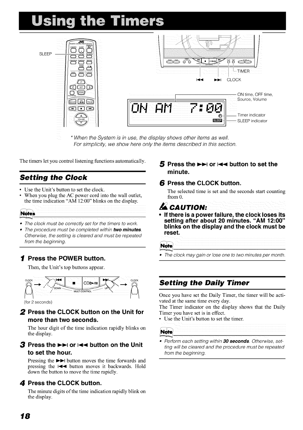
SLEEP
I<< _ CLOCK
ON time, OFF time,
' I , Source, Volume
•I Ir.'l., [] .
Timer indicatorI
SLEEPindicator
* When the System is in use, the display shows other items as well.
For simplicity, we show here only the items described in this section.
The timers let you control listening functions automatically.
Setting the Clock
• Use the Unit's button to set the clock.
• When you plug the AC power cord into the wall outlet,
the time indication "AM 12:00" blinks on the display.
•The clock must be correctly set for the timers to work.
• The procedure must be completed within two minutes.
Otherwise, the setting is cleared and must be repeated
from the beginning.
1Press the POWER button.
Then, the Unit's top buttons appear.
iconiC__,
(for 2 seconds)
2Press the CLOCK button on the Unit for
more than two seconds.
The hour digit of the time indication rapidly blinks on
the display.
3Press the _or I<< button on the Unit
to set the hour.
Pressing the _ button moves the time forwards and
pressing the _ button moves it backwards. Hold
down the button to move the time rapidly.
4Press the CLOCK button.
The minute digits of the time indication rapidly blink on
the display.
5Press the _or I<< button to set the
minute.
6Press the CLOCK button.
The selected time is set and the seconds start counting
from 0.
cAurroN-
•If there is a power failure, the clock loses its
setting after about 20 minutes. "AM 12:00"
blinks on the display and the clock must be
reset.
• Theclock may gain or lose one to two minutes per month.
Setting the Daily Timer
Once you have set the Daily Timer, the timer will be acti-
vated at the same time every day.
The Timer indicator on the display shows that the Daily
Timer you have set is in effect.
• Use the Unit's button to set the timer.
• Perform each setting within 30 seconds Otherwise, set-
ting will be cleared and the procedure must be repeated
from the beginning.
18
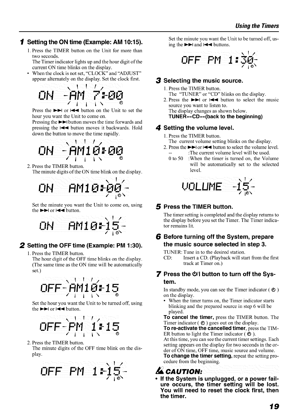
1[ Setting the ON time (Example: AM 10:15).
1.Press the TIMER button on the Unit for more than
two seconds.
The Timer indicator lights up and the hour digit of the
current ON time blinks on the display.
• When the clock is not set, °'CLOCK" and "ADJUST"
appear alternately on the display. Set the clock first.
UI"I _r'll'l i" _iyj
"i I L\ e
Press the _ or 1<1<1button on the Unit to set the
hour you want the Unit to come on.
Pressing the _ button moves the time forwards and
pressing the 1<1<button moves it backwards. Hold
down the button to move the time rapidly.
\ Y /
ON I 111
/I i ix e
2. Press the TIMER button.
The minute digits of the ON time blink on the display.
\ I /
ON RF,1I0 :- 30
Set the minute you want the Unit to come on, using
the _ or _ button.
xl /
....... k:t"-i 5I IP.I I_lrll 1
I.JI 1 I II IJL /ie\
2Setting the OFF time (Example: PM 1:30).
1.Press the TIMER button.
The hour digit of the OFF time blinks on the display.
(The same time as the ON time will be automatically
set.)
\II!/
OFF' FIHi:-I5
Ii 1 ix e
Set the hour you want the Unit to be turned off, using
the _ or 1<1<button.
I v # j
I "Pt,'., i, :-i 5OFF... _
iIiIx e
2. Press the TIMER button.
The minute digits of the OFF time blink on the dis-
play.
\ I /
OFF PH 1.-15 -
Using the Timers
Set the minute you want the Unit to be turned off, us-
ing the _ and 1<1<buttons.
\II
0 I" I_" _ I .._ ..i.
rr rl,l" --" v..iT
/i¢ _
3Selecting the music source.
l. Press the TIMER button.
The "TUNER" or "CD" blinks on the display.
2. Press the _ or 1<1< button to select the music
source you want to listen to.
The display changes as shown below.
TUNER*-,CD*-,(back to the beginning)
4Setting the volume level.
l. Press the TIMER button.
The current volume setting blinks on the display.
2. Press the _ or 1<1<button to select the volume level.
-- :The current volume level will be used.
0 to 50 :When the timer is turned on, the Volume
will be automatically set to the selected
level.
\ I I
UL1LUHE ,15
/ie\
5Press the TIMER button.
The timer setting is completed and the display returns to
the display before you set the Timer. The Timer indica-
tor remains lit.
6
7
Before turning off the System, prepare
the music source selected in step 3.
TUNER: Tune in to the desired station.
CD: Insert a CD. (Playback will start from the first
track at Timer on.)
Press the (5/I button to turn off the Sys-
tem.
In standby mode, you can see the Timer indicator ( _1)
on the display.
• When the timer turns on, the Timer indicator starts
blinking and the prepared source in step 6 will be
played.
TO cancel the timer, press the TIMER button. The
Timer indicator ( _ ) goes out on the display.
To re-activate the cancelled timer, press the TIM-
ER button to light the Timer indicator (_) ).
At this time, you can see the current timer settings. Each
setting appears on the display for two seconds in the or-
der of ON time, OFF time, music source and volume.
To change the timer setting, repeat the setting pro-
cedure from the beginning.
.'_ CAUTION:
•If the System is unplugged, or a power fail-
ure occurs, the timer setting will be lost.
You will need to reset the clock first, then
the timer.
19
Using the Timers
Setting the SLEEP Timer
(Using the Remote Control)
Use the Sleep Timer to turn the System oft" after a certain
number of minutes when it is playing. By setting the Sleep
Timer, you can fall asleep to music and know that your Sys-
tem will turn off by itself rather than play all night.
• You can only set the Sleep Timer when the System is on
and a source is playing.
1Play a CD or tune in to the desired sta-
tion.
2Press the SLEEP button on the Remote
Control.
The "SLEEP" indicator lights up.
• When the clock is not set, "CLOCK" and "ADJUST"
appear alternately on the display. Set the clock at first.
3Set the length of time you want the
source to play before shutting off.
• Each time you press the SLEEP button, it changes
the number of minutes shown on the display in this
sequence:
10 -- 20 -- 30 -, 60 -, 90 -_ 120 -- Cancelled --
(back to the beginning)
The selected number of minutes for the Sleep Timer will
stop blinking five seconds later and the display returns to
the original one before setting the Sleep Timer. (The display
is dimmed.)
The System is now set to turn off after the number of min-
utes you set.
To Confirm the Sleep Time:
When the SLEEP button is pressed, the remaining sleep
time is displayed. Wait until the display returns to the orig-
inal display.
To Cancel the SLEEP Timer Setting:
Press the SLEEP button until the "SLEEP" indicator goes
out on the display.
Turning off the System also cancels the SLEEP Timer.
• If you are setting the Daily Timer, the System will be
turned on at the set time to wake you up.
2O
Handle your CDs carefully, and they will last a long time.
Compact Discs
[_lm1_LDJmlO
x@
•Only CDs bearing this mark can
be used with this System. How-
ever, continued use of irregular
shape CDs (heart-shape, octago-
nal, etc.) can damage the System.
• Remove the CD from its case by
holding it at the edges while press-
ing the case's center hole lightly.
• Do not touch the shiny surface of
the CD, or bend the CD.
• Put the CD back in its case after
use to prevent warping.
• Be careful not to scratch the sur-
face of the CD when placing it
back in the case.
• Avoid exposure to direct sunlight,
temperature extremes, and moisture.
A dirty CD may not play cor-
rectly. If a CD does become dirty,
wipe it with a soft cloth in a
straight line from center to edge.
CAUTION-
•Do not use any solvent (for example, con-
ventional record cleaner, spray thinner,
benzine, etc.) to clean a CD.
General Notes
In general, you will have the best performance by keeping
your CDs and the mechanism clean.
• Store CDs in their cases, and keep them in cabinets or on
shelves.
• Keep the System's Top Cover closed when not in use.
Cleaning the unit
•Stains on the unit
Should be wiped off with a soft cloth. If the unit is heavily
stained, wipe it witha cloth soaked in water-diluted neutral
detergent and wrung well, then wipe clean with a dry cloth.
• Since the unit may deteriorate in quality, become damaged
or get its paint peeled off, be careful about the followings.
- DO NOT wipe it with a hard cloth.
- DO NOT wipe it strong.
- DO NOT wipe it with thinner or benzine.
- DO NOT apply any volatile substance such as insecti-
cides to it.
- DO NOT allow any rubber or plastic to remain in con-
tact with it for a long time.
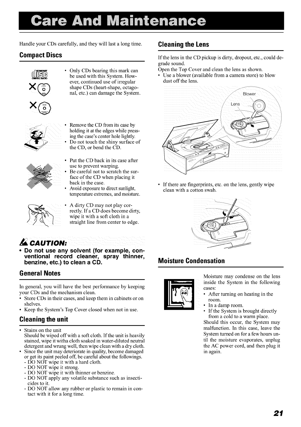
Cleaning the Lens
If the lens in the CD pickup is dirty, dropout, etc., could de-
grade sound.
Open the Top Cover and clean the lens as shown.
• Use a blower (available from a camera store) to blow
dust off the lens.
Blower
If there are fingerprints, etc. on the lens, gently wipe
clean with a cotton swab.
Moisture Condensation
ii
Moisture may condense on the lens
inside the System in the following
cases:
• After turning on heating in the
room.
• In a damp room.
• If the System is brought directly
from a cold to a warm place.
Should this occur, the System may
malfunction. In this case, leave the
System turned on for a few hours un-
til the moisture evaporates, unplug
the AC power cord, and then plug it
in again.
21
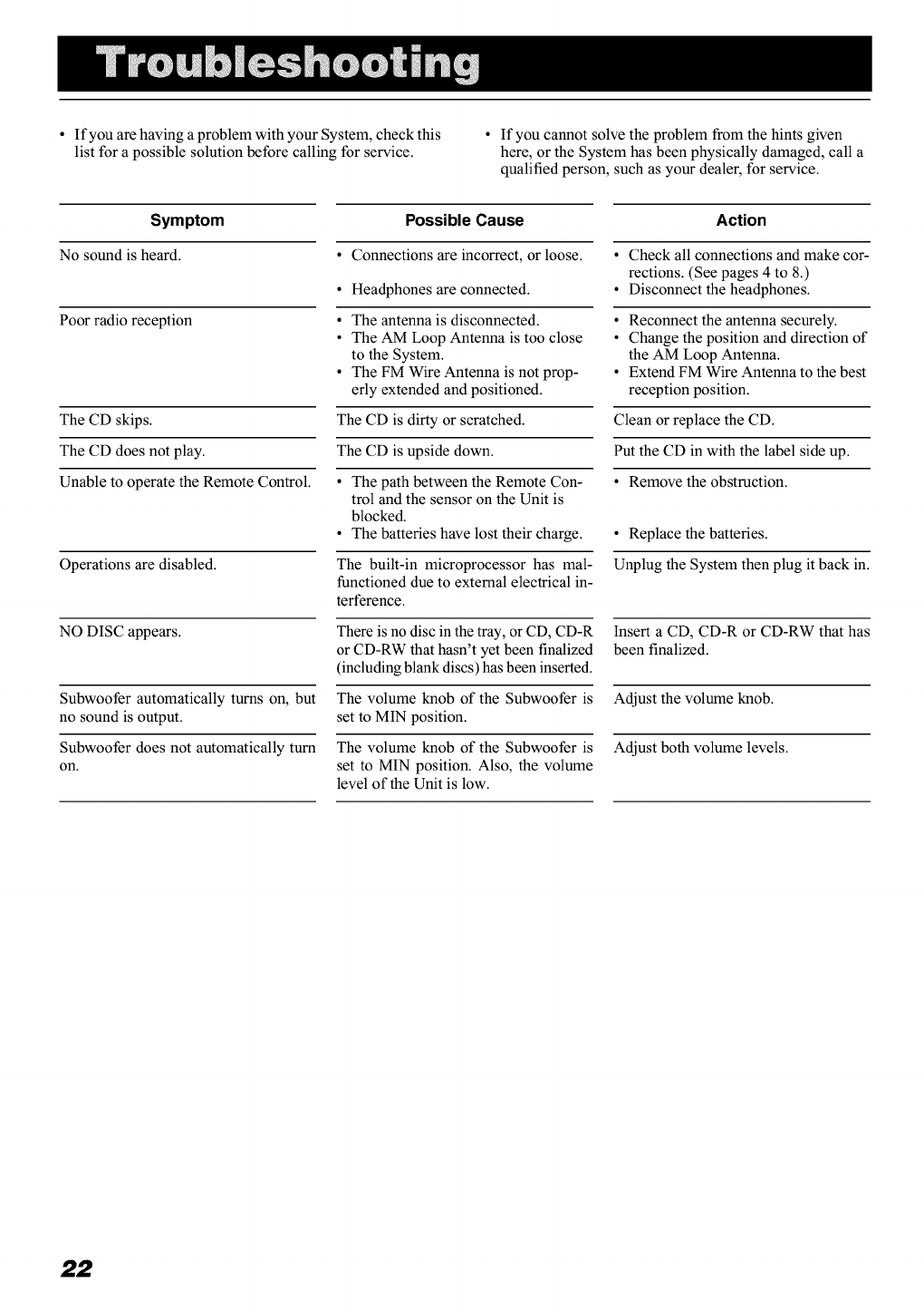
• If you are having a problem with your System, check this
list for a possible solution before calling for service. • If you cannot solve the problem from the hints given
here, or the System has been physically damaged, call a
qualified person, such as your dealer, for service.
Symptom
No sound is heard.
Poor radio reception
The CD skips.
The CD does not play.
Unable to operate the Remote Control.
Operations are disabled.
NO DISC appears.
Subwoofer automatically turns on, but
no sound is output.
Subwoofer does not automatically turn
on.
Possible Cause
• Connections are incorrect, or loose.
• Headphones are connected.
• The antenna is disconnected.
• The AM Loop Antenna is too close
to the System.
• The FM Wire Antenna is not prop-
erly extended and positioned.
The CD is dirty or scratched.
The CD is upside down.
• The path between the Remote Con-
trol and the sensor on the Unit is
blocked.
• The batteries have lost their charge.
The built-in microprocessor has mal-
functioned due to external electrical in-
terference.
There is no disc in the tray, or CD, CD-R
or CD-RW that hasn't yet been finalized
(including blank discs) has been inserted.
The volume knob of the Subwoofer is
set to MIN position.
The volume knob of the Subwoofer is
set to MIN position. Also, the volume
level of the Unit is low.
Action
• Check all connections and make cor-
rections. (See pages 4 to 8.)
• Disconnect the headphones.
• Reconnect the antenna securely.
• Change the position and direction of
the AM Loop Antenna.
• Extend FM Wire Antenna to the best
reception position.
Clean or replace the CD.
Put the CD in with the label side up.
• Remove the obstruction.
• Replace the batteries.
Unplug the System then plug it back in.
Insert a CD, CD-R or CD-RW that has
been finalized.
Adjust the volume knob.
Adjust both volume levels.
22
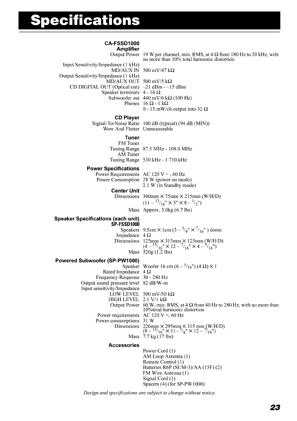
CA-FSSD1000
Amplifier
Output Power
Input Sensitivity/Impedance (1 kHz)
MD/AUX IN
Output Sensitivity/Impedance (1 kHz)
MD/AUX OUT
CD DIGITAL OUT (Optical out)
Speaker terminals
Subwoofer out
Phones
CD Player
Signal-To-Noise Ratio
Wow And Flutter
19 W per channel, min. RMS, at 4 _ from 180 Hz to 20 kHz, with
no more than 10% total harmonic distortion
500 mV/47 k_
500 mV/5 k_
-21 dBm--15 dBm
4-16_
440 mV/6 k_ (100 Hz)
16_- 1k_
0 - 15 mW/ch output into 32
100 dB (typical) (94 dB (MIN))
Unmeasurable
Tuner
FM Tuner
Tuning Range
AM Tuner
Tuning Range
Power Specifications
Power Requirements
Power Consumption
Center Unit
Dimensions
Mass
Speaker Specifications (each unit)
SP-FSSD1000
Speakers
Impedance
Dimensions
Mass
Powered Subwoofer (SP-PW1000)
Speaker
Rated Impedance
Frequency Response
Output sound pressure level
Input sensitivity/Impedance
LOW LEVEL
HIGH LEVEL
Output Power
Power requirements
Power consumptions
Dimensions
Mass
Accessories
87.5 MHz - 108.0 MHz
530 kHz - 1 710 kHz
AC 120 V ~, 60 Hz
28 W (power on mode)
2.1 W (in Standby mode)
300mm × 75mm × 215mm (W/H/D)
(11 -13/16"X 3" X 8 -1/2")
Approx. 3.0kg (6.7 lbs)
9.5cm × lcm (3 -3/4" X 7/16" ) dome
4_
125mm × 315mm × 125mm (W/H/D)
(4 - 15/16"× 12- 7/16" × 4 -5/16" )
520g (1.2 lbs)
Woofer 16 cm (6 - 5/16") (4 _) × 1
30 - 280 Hz
82 dBfW-m
500 mW50 k£_
2.1 V/1 k£_
60 W, min. RMS, at 4 £_ from 40 Hz to 280 Hz, with no more than
10%total harmonic distortion
AC 120 V ~, 60 Hz
31W
226mm X,,295mrrt ×,,315 mm (W,/tt/D)
(8-15/16 ×11-5/8 ×12-7316)
7.7 kg (17 lbs)
Power Cord (1)
AM Loop Antenna (1)
Remote Control (1)
Batteries R6P (SUM-3)/AA (15F) (2)
FM Wire Antenna (1)
Signal Cord (1)
Spacers (4) (for SP-PW 1000)
Design and specifications are subject to change without notice.
23
O0 't 'JVC
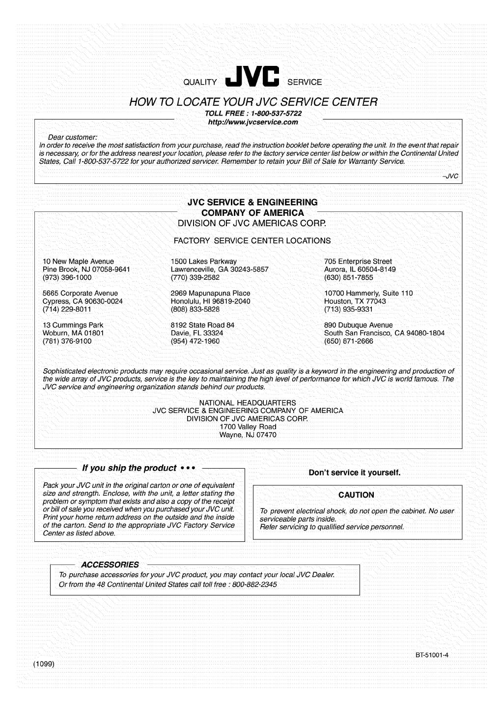
HOW TO LOCATE YOUR JVC SERVICE CENTER
TOLL FREE : 1-800-537-5722
http://www.jvcservice.com
Dear customer:
In order to receive the most satisfaction from your purchase, read the instruction booklet before operating the unit. In the event that repair
is necessary, or for the address nearest your location, please refer to the factory service center list below or within the Continental United
States, Call 1-800-537-5722 for your authorized servicer. Remember to retain your Bill of Sale for Warranty Service.
-JVC
JVC SERVICE & ENGINEERING
COMPANY OF AMERICA
DIVISION OF JVC AMERICAS CORP.
FACTORY SERVICE CENTER LOCATIONS
10 New Maple Avenue 1500 Lakes Parkway
Pine Brook, NJ 07058-9641 Lawrenceville. GA 30243-5857
(973) 396-1000 (770) 339-2582
705 Enterprise Street
Aurora. IL 60504-8149
(630) 851-7855
5665 Corporate Avenue 2969 Mapunapuna Place 10700 Hammerly, Suite 110
Cypres& CA 90630-0024 Honolulu. HI 96819-2040 Houston. TX 77043
(714) 229-8011 (808) 833-5828 (713) 935-9331
13 Cummings Park 8192 State Road 84
Woburn, MA 01801 Davie. FL 33324
(781) 376-9100 (954) 472-1960
890 Dubuque Avenue
South San Francisco, CA 94080-1804
(650) 871-2666
Sophisticated electronic products may require occasional service. Just as quality is a keyword in the engineering and production of
the wide array of JVC products, service is the key to maintaining the high level of performance for which JVC is world famous. The
JVC service and engineenng organization stands behind our products.
NATIONAL HEADQUARTERS
JVC SERVICE & ENGINEERING COMPANY OF AMERICA
DIVISION OF JVC AMERICAS CORP
1700 Valley Road
Wayne, NJ 07470
If you ship the product ••°
Pack your JVC unit in the original carton or one of equivalent
size and strength. Enclose, with the unit. a letter stating the
problem or symptom that exists and also a copy of the receipt
or bill of sale you received when you purchased your JVC unit.
Print your home return address on the outside and the inside
of the carton. Send to the appropriate JVC Factory Service
Center as listed above.
Don't service it yourself.
CAUTION
To prevent electrical shock, do not open the cabinet. No user
serviceable parts inside.
Refer servicing to qualified service personnel.
-- ACCESSORIES
To purchase accessories for your JVC product, you may contact your local JVC Dealer.
Or from the 48 Continental United States call toll free : 800-882-2345
(1099)
BT-51001-4
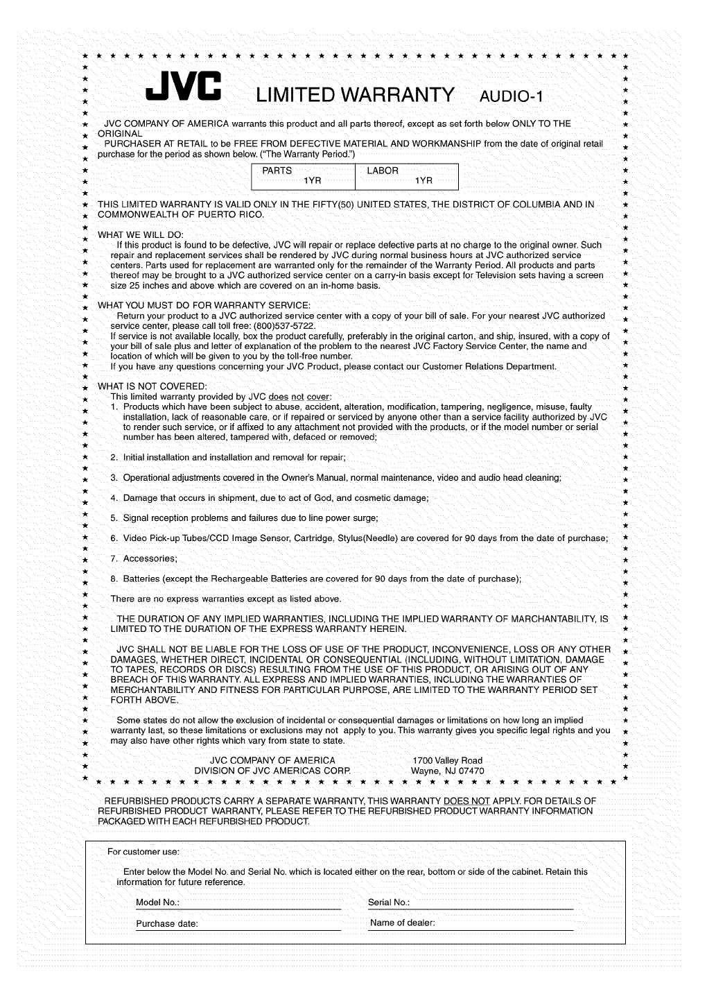
"JVC
* LIMITED WARRANTY AUDIO 1
*JVC COMPANY OF AMERICA warrants this product and all parts thereof, except as set forth below ONLY TO THE
. ORIGINAL
.PURCHASER AT RETAIL to be FREE FROM DEFECTIVE MATERIAL AND WORKMANSHIP from the date of original retail
. purchase for the period as shown below. ("The Warranty Period."}
*PARTS LABOR
.1YR 1YR
*THIS LIMITED WARRANTY IS VALID ONLY IN THE FIFTY(50) UNITED STATES THE DISTRICT OF COLUMBIA AND IN
. COMMONWEALTH OF PUERTO RICO. .
WHAT WE WILL DO:
If this product is found to be defective, JVC will repair or replace defective parts at no charge to the original owner. Such
repair and replacement services shall be rendered by JVC during normal business hours at JVC authorized service
*centers. Parts used for replacement are warranted only for the remainder of the Warranty Period. All products and parts *
* thereof may be brought to a JVC authorized service center on a carry-in basis except for Television sets having a screen *
.k size 25 inches and above which are covered on an in-home basis. *
. WHATYOU MUST DO FOR WARRANTY SERVICE: .
. Return your product to a JVC authorized service center with a copy of your bill of sale. For your nearest JVC authorized .
service center, please call toll free: (800)537-5722.
f service is not available locally, box the product carefully, preferably in the original carton, and ship, insured, with a copy of
*your bill of sale plus and letter of explanation of the problem to the nearest JVC Factory Service Center, the name and *
*location of which wilt be given to you by the toll-free number. *
*f you have any questions concerning your JVC Product. please contact our Customer Relations Department. _'
. WHAT IS NOT COVERED: .
.This limited warranty provided by JVC does not cover: .
.1. Products which have been subject to abuse, accident, alteration, modification, tampering, negligence, misuse, faulty .
installation, lack of reasonable care. or if repaired or serviced by anyone other than a service facility authorized by JVC
*to render such service, or if affixed to any attachment not _rovided with the products, or if the model number or serial *
*number has been altered, tampered with. defaced or removed:
*2. Initial installation and installation and removal for repair:
. 3. Operational adjustments covered in the Owner's Manual. normal maintenance video and audio head cleaning;
.,k
.4. Damage that occurs in shipment, due to act of God, and cosmetic damage; .
*5. Signal reception problems and failures due to line power surge; *
* 6. Video Pick-uP Tubes/CCD Image Sensor. Cartridge, Stylus(Needle) are covered for 90 days from the date of purchase: *
.7. Accessories: .
.8. Batteries (except the Rechargeable Batteries are covered for 90 days from the date of purchase); .
There are no express warranties except as listed above.
THE DURATION OF ANY IMPLIED WARRANTIES, NCLUDING THE IMPLIED WARRANTY OF MARCHANTABILITY. IS
_IMITED TO THE DURATION OF THE EXPRESS WARRANTY HEREIN.
JVC SHALL NOT BE LIABLE FOR THE LOSS OF USE OF THE PRODUCT INCONVENIENCE. LOSS OR ANY OTHER
DAMAGES. WHETHER DIRECT. INCIDENTAL OR CONSEQUENTIAL (INCLUDING, WITHOUT LIMITATION DAMAGE
TO TAPES. RECORDS OR DISCSI RESULTING FROM THE USE OFTHIS PRODUCT. OR ARISING OUT OF ANY
3REACH OF THIS WARRANTY. ALL EXPRESS AND IMPLIED WARRANTIES, INCLUDING THE WARRANTIES OF
VIERCHANTABILITY AND FITNESS FOR PARTICULAR PURPOSE ARE LIMITED TO THE WARRANTY PERIOD SET
FORTH ABOVE.
Some states do not allow the exclusion of incidental or consequential damages or limitations on how long an implied
warranty last. so these limitations or exclusions may not apply to you. This warranty gives you specific legal rights and you
may also have other rights which vary from state to state.
JVC COMPANY OF AMERICA 1700 Valley Roac
DIVISION OF JVC AMERICAS CORP. Wayne, NJ 07470
REFURBISHED PRODUCTS CARRY A SEPARATE WARRANTY THIS WARRANTY DOES NOT APPLY. FOR DETAILS OF
REFURBISHED PRODUCT WARRANTY. PLEASE REFER TO THE REFURBISHED PRODUCT WARRANTY INFORMATION
PACKAGED WITH EACH REFURBISHED PRODUCT.
For customer use:
Enter below the Model No. and Serial No. which is located either on the rear. bottom or side of the cabinet. Retain this
information for future reference.
Model No, Serial No.:
Purchase date: Name of dealer:

i
i
/
JVl¢
VICTOR COMPANY OF JAPAN, LIMITED
/_EN 0201MNMCREH!T
