JVC GY HD250/251 H250 User Manual LST0440 001B H
User Manual: JVC GY-HD250/251 GY-HD250/251 English,
Open the PDF directly: View PDF ![]() .
.
Page Count: 118 [warning: Documents this large are best viewed by clicking the View PDF Link!]
- ACCESSORIES
- MAIN FEATURES
- INTRODUCTION
- CONTROLS, INDICATORS AND CONNECTORS
- ZOOM Lens
- Front Section
- Rear Section
- LCD Door
- Right Side Section
- Left Side Section
- Top Section
- Recording and Image Output Formats
- Indications on the LCD Monitor and in the Viewfinder
- Status Screens
- Status Screens in the Camera Mode
- Status Screen in VTR MODE
- Magnified Status Indications on the LCD Monitor
- Auto White Balance Indication (Camera mode only)
- Menu Setting Screen
- Alarm Message Display
- Safety Zone Indication (Camera mode only)
- Switching between the LCD Screen and Viewfinder Display
- PREPARATIONS
- PREPARATIONS FOR OPERATION
- Turning the Power ON
- Loading/Unloading the Cassette
- Setting and Displaying the Date and Time
- Displaying Time Code
- Presetting and Recording of Time Code
- Presetting the Time Code from the LCD Screen
- Recording Time Codes in Continuation of Time Codes Recorded on Tape
- Playing Back Time Code
- Synchronizing with the Time Code of the IEEE1394 (DV)-Connected Master Unit
- Synchronizing with an External Time Code Generator
- Screen Adjustment
- Viewfinder Adjustment
- Back Focus Adjustment
- White Balance Adjustment
- White Shading Adjustment
- SETTING AND ADJUSTMENTS BEFORE SHOOTING
- SHOOTING OPERATION
- PLAYBACK MODE
- USING EXTERNAL COMPONENTS
- MENU SCREENS
- Menu Screen Configuration
- Setting Menu Screens
- TOP MENU Screen
- VIDEO FORMAT[1/2] Menu Screen
- VIDEO FORMAT[2/2] Menu Screen
- CAMERA OPERATION Menu Screen
- CAMERA PROCESS[1/2] Menu Screen
- CAMERA PROCESS[2/2] Menu Screen
- ADVANCED PROCESS Menu Screen
- COLOR MATRIX ADJUST Menu Screen
- SKIN COLOR ADJUST Menu Screen
- WHITE BALANCE Menu Screen
- SWITCH MODE Menu Screen
- AUDIO/MIC[1/2] Menu Screen
- AUDIO/MIC[2/2] Menu Screen
- LCD/VF[1/4] Menu Screen
- LCD/VF[2/4] Menu Screen
- LCD/VF[3/4] Menu Screen
- LCD/VF[4/4] Menu Screen
- TC/UB/CLOCK Menu Screen
- HEADER REC Menu Screen
- TIME/DATE Menu Screen
- OTHERS[1/2] Menu Screen
- OTHERS[2/2] Menu Screen
- GENLOCK Menu Screen
- FILE MANAGE Menu Screen
- FEATURES OF THE CAMERA SECTION
- OTHERS
INTRODUCTION
CONTROLS,
INDICATORS AND
CONNECTORS
PREPARATIONS
PREPARATIONS
FOR OPERATION
SETTING AND
ADJUSTMENTS
BEFORE SHOOTING
SHOOTING
OPERATION
PLAYBACK MODE
USING EXTERNAL
COMPONENTS
MENU SCREENS
FEATURES OF THE
CAMERA SECTION
OTHERS
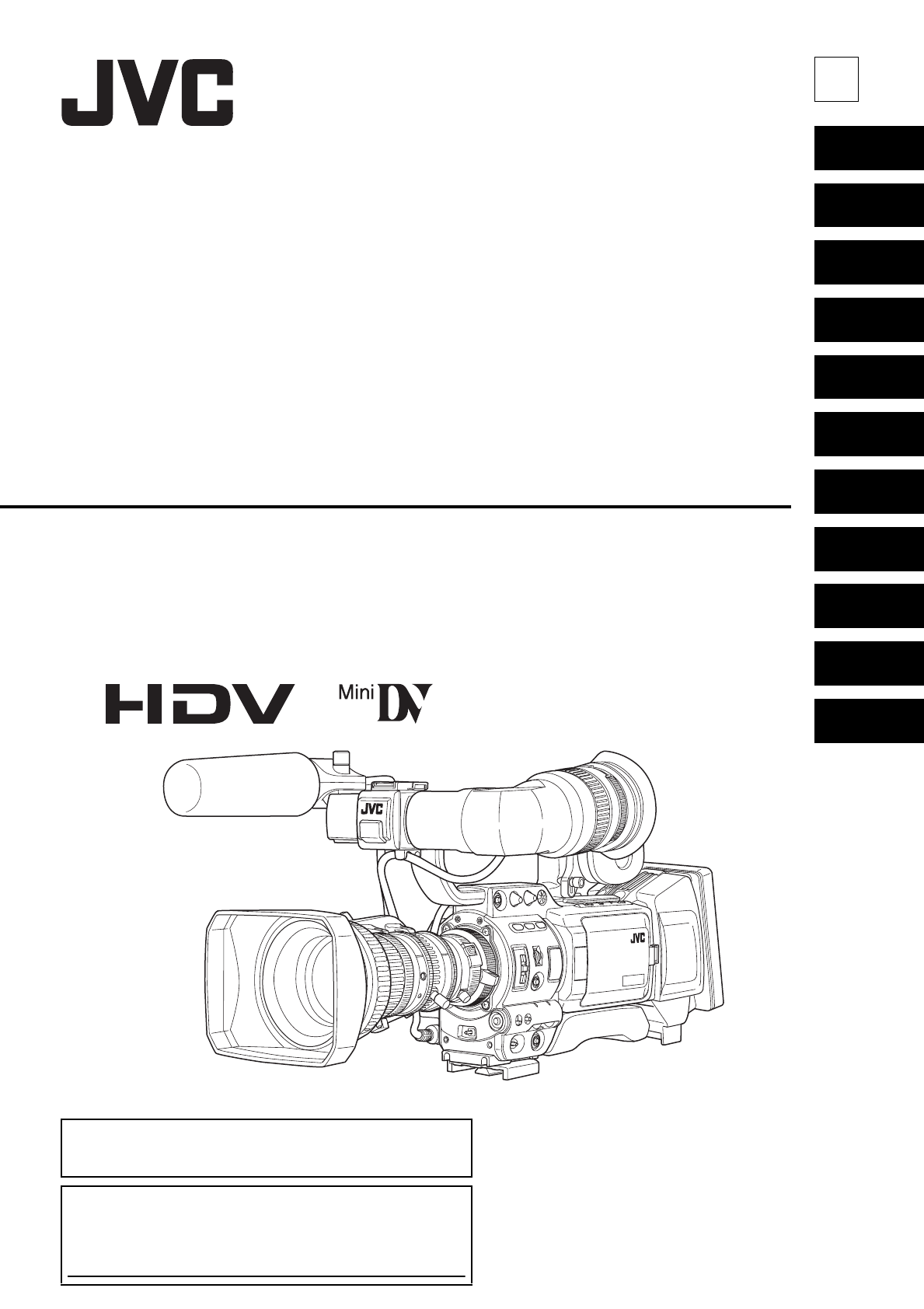
HD CAMERA RECORDER
INSTRUCTIONS
GY-HD250
GY-HD251
* The illustration shows the GY-HD250/GY-
HD251 HD CAMERA RECORDER with the
provided lens, viewfinder and microphone
attached.
LST0440-001B
E
GY-HD250/GY-HD251
HD CAMERA RECORDER
Thank you for purchasing this JVC product. Before operating this
device, please read the instructions carefully to ensure the best
possible performance.
For Customer Use:
Enter below the Serial No. which is located on the body.
Retain this information for future reference.
Model No.
Serial No.
© 2006 Victor Company of Japan, Limited LST0440-001B
I
Important Safeguards
1. Read all of these instructions.
2. Keep these instructions.
3. Heed all warnings.
4. Follow all instructions.
5. Do not use this apparatus near water.
6. Clean only with dry cloth.
7. Do not block any ventilation openings. Install in accor-
dance with the manufacturer’s instructions.
8. Do not install near any heat sources such as radia-
tors, heat resisters, stoves, or other apparatus
(including amplifiers) that produce heat.
9. Do not defeat the safety purpose of the polarized or
grounding-type plug. A polarized plug has two blades
with one wider than the other. A grounding type plug
has two blades and a third grounding prong.
The wide blade or the third prong are provided for
your safety.
If the provided plug does not fit into your outlet, con-
sult an electrician for replacement of the obsolete out-
let.
10. Protect the power cord from being walked on or
pinched particularly at plug, convenience receptacles,
and the point where they exit from the apparatus.
11. Only use attachments/accessories specified by the
manufacturer.
12. Use only with the cart, stand, tripod,
bracket, or table specified by the
manufacturer, or sold with the appa-
ratus.
When a cart is used, use caution
when moving the cart/apparatus
combination to avoid injury tip-over.
13. Unplug this apparatus during light-
ning storms or when unused for long periods of time.
14. Refer all servicing to qualified service personnel. Ser-
vicing is required when the apparatus has been dam-
aged in any way, such as power-supply cord or plug
id damaged, liquid has been spilled objects have
fallen into the apparatus, the apparatus has been
exposed to rain or moisture, does not operate nor-
mally, or has been dropped.
II
Safety Precautions
FOR USA AND CANADA
CAUTION
RISK OF ELECTRIC SHOCK
DO NOT OPEN
CAUTION: TO REDUCE THE RISK OF ELECTRIC SHOCK,
DO NOT REMOVE COVER (OR BACK).
NO USER SERVICEABLE PARTS INSIDE.
REFER SERVICING TO QUALIFIED SERVICE PERSONNEL.
The lightning flash with arrowhead symbol, within
an equilateral triangle is intended to alert the user
to the presence of uninsulated “dangerous voltage”
within the product’s enclosure that may be of suffi-
cient magnitude to constitute a risk of electric shock
to persons.
The exclamation point within an equilateral triangle
is intended to alert the user to the presence of
important operating and maintenance (servicing)
instructions in the literature accompanying the
appliance.
INFORMATION FOR USA
INFORMATION:
This equipment has been tested and found to comply with the
limits for a Class B digital device, pursuant to Part 15 of the
FCC Rules.
These limits are designed to provide reasonable protection
against harmful interference in a residential installation. This
equipment generates, uses, and can radiate radio frequency
energy and, if not installed and used in accordance with the
instructions, may cause harmful interference to radio communi-
cations. However, there is no guarantee that interference will
not occur in a particular installation.
If this equipment does cause harmful interference to radio or
television reception, which can be determined by turning the
equipment off and on, the user is encouraged to try to correct
the interference by one or more of the following measures:
zReorient or relocate the receiving antenna.
zIncrease the separation between the equipment and
receiver.
zConnect the equipment into an outlet on a circuit different
from that to which the receiver is connected.
zConsult the dealer or an experienced radio/TV technician for
help.
CAUTION:
CHANGES OR MODIFICATIONS NOT APPROVED BY JVC
COULD VOID USER’S AUTHORITY TO OPERATE THE
EQUIPMENT.
THIS DEVICE COMPLIES WITH PART 15 OF THE FCC
RULES.
OPERATION IS SUBJECT TO THE FOLLOWING TWO CON-
DITIONS: (1) THIS DEVICE MAY NOT CAUSE HARMFUL
INTERFERENCE, AND (2) THIS DEVICE MUST ACCEPT
ANY INTERFERENCE RECEIVED, INCLUDING INTERFER-
ENCE THAT MAY CAUSE UNDESIRED OPERATION.
INFORMATION (FOR CANADA)
RENSEIGNEMENT (POUR CANADA)
This Class B digital apparatus complies with Canadian ICES-
003.
Cet appareil numérique de la Classe B est conforme à la
norme NMB-003 du Canada.
WARNING:
TO REDUCE THE RISK OF FIRE OR ELEC-
TRIC SHOCK, DO NOT EXPOSE THIS
APPLIANCE TO RAIN OR MOISTURE.
This unit should be used with 12V DC only.
CAUTION:
To prevent electric shocks and fire hazards, do NOT
use any other power source.
NOTE:
The rating plate (serial number plate) is on the bottom of the unit.
CAUTION:
To prevent electric shock, do not open the cabinet. No user ser-
viceable parts inside. Refer servicing to qualified service person-
nel.
AVERTISSEMENT :
POUR EVITER LES RISQUES D’INCENDIE
OU D’ELECTROCUTION, NE PAS EXPOSER
L’APPAREIL A L’HUMIDITE OU A LA PLUIE.
Ce magnétoscope ne doit être utilisé que sur du cou-
rant direct en 12V.
ATTENTION :
Afin d’eviter tout resque d’incendie ou d’électrocu-
tion, ne pas utillser d’autres sources d’alimentation
électrique.
REMARQUE:
La plaque signalétique (plaque du numéro desérie) est située sur
le cadre inférieur de l’unité.
Due to design modifications, data given in this instruction book are
subject to possible change without prior notice.
The apparatus shall not be exposed to dripping or splashing and
that no objects filled with liquids, such as vases, shall be placed
close to the apparatus.
Worded - “CAUTION - Danger of explosion if battery is incorrectly
replaced. Replace only with the same or equivalent type.”
III
Safety Precautions (Cont’d)
FOR EUROPE
This equipment is in conformity with the provisions and protection
requirements of the corresponding European Directives.
This equipment is designed for professional video appliances and
can be used in the following environments:
zresidential area (in houses)
zcommercial and light industry; e.g. offices or theatres
zurban outdoors
In order to keep the best performance and furthermore for electro-
magnetic compatibility we recommend to use cables not exceeding
the following length:
Camera
Caution: Where there are strong electromagnetic waves or mag-
netism, for example near a radio or TV transmitter, transformer,
motor, etc., the picture and the sound may be disturbed. In such
case, please keep the apparatus away from the sources of the dis-
turbance.
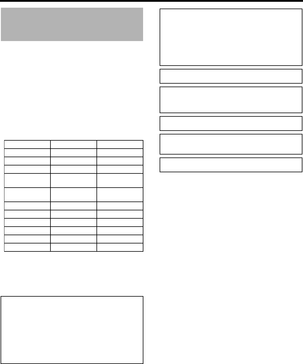
Port Cable Length
DC IN Exclusive Cable 2 m
VIDEO Coaxial Cable 3 m
Y, P B, PRCoaxial Cable 3 m
AUDIO INPUT1,
INPUT2
Shielded Cable 3 m
AUDIO OUT CH1,
CH2
Shielded Cable 3 m
Phones1, 2 Exclusive Cable 2 m
IEEE1394 (HDV/DV)
Exclusive Cable 4.5 m
GENLOCK/AUX IN Coaxial Cable 3 m
HD/SD-SDI Coaxial Cable 3 m
REMOTE Exclusive Cable 5 m
STUDIO Exclusive Cable 1 m
Dear Customer,
This apparatus is in conformance with the valid European direc-
tives and standards regarding electromagnetic compatibility and
electrical safety.
European representative of Victor Company of Japan Limited is:
JVC Technology Centre Europe GmbH
P.O. Box 10 05 52
61145 Friedberg
Germany
WARNING:
TO REDUCE THE RISK OF FIRE OR
ELECTRIC SHOCK, DO NOT EXPOSE THIS
APPLIANCE TO RAIN OR MOISTURE.
This unit should be used with 12V DC only.
CAUTION:
To prevent electric shocks and fire hazards, do NOT
use any other power source.
NOTE:
The rating plate (serial number plate) is on the bottom of the unit.
CAUTION:
To prevent electric shock, do not open the cabinet. No user ser-
viceable parts inside. Refer servicing to qualified service person-
nel.
Due to design modifications, data given in this instruction book are
subject to possible change without prior notice.
The apparatus shall not be exposed to dripping or splashing and
that no objects filled with liquids, such as vases, shall be placed
close to the apparatus.
Worded - “CAUTION - Danger of explosion if battery is incorrectly
replaced. Replace only with the same or equivalent type.”

IV
Information for Users on Disposal of
Old Equipment
[European Union]
This symbol indicates that the electrical and electronic equip-
ment should not be disposed as general household waste at
its end-of-life. Instead, the product should be handed over to
the applicable collection point for the recycling of electrical
and electronic equipment for proper treatment, recovery and
recycling in accordance with your national legislation.
By disposing of this product correctly, you will help to con-
serve natural resources and will help prevent potential nega-
tive effects on the environment and human health which
could otherwise be caused by inappropriate waste handling
of this product. For more information about collection point
and recycling of this product, please contact your local
municipal office, your household waste disposal service or
the shop where you purchased the product.
Penalties may be applicable for incorrect disposal of this
waste, in accordance with national legislation.
(Business users)
If you wish to dispose of this product, please visit our web
page www.jvc-europe.com to obtain information about the
take-back of the product.
[Other Countries outside the European Union]
If you wish to dispose of this product, please do so in accor-
dance with applicable national legislation or other rules in
your country for the treatment of old electrical and electronic
equipment.
Attention:
This symbol is only valid in the European
Union.
2
Thank you for purchasing the JVC GY-HD250U/CHU and
GY-HD251E/CHE HD CAMERA RECORDER.
These instructions are for the GY-HD250U/CHU and GY-
HD251E/CHE.
• A lens is included with the GY-HD250U and GY-HD251E.
• A lens is not included with the GY-HD250CHU and GY-
HD251CHE.
Information applicable only to the GY-HD250U/CHU is
marked by “(U model only)”.
Information applicable only to the GY-HD251E/CHE is
marked by “(E model only)”.
* All product names in this manual are trademarks or regis-
tered trademarks of their respective companies.
Marks such as ™, ® and © are not used in this manual.
ACCESSORIES
This device is a HDV/DV video system format camera
recorder.
Videocassettes marked with the A symbol can be used.
The following phenomena may occur when tapes recorded
on other units (including another GY-HD250/GY-HD251)
are recorded or played back on GY-HD250/GY-HD251.
• The transient section between scenes recorded on other
units and those recorded on this device may appear dis-
turbed.
• Digital noise may appear during playback due to track-
ing errors.
• This device records and plays back in the SP mode.
Recording or playback in the LP mode is not possible.
(In DV format)
• Due to manufacturing dispersion of tapes, we recom-
mend not to record pictures within the first 2 to 3 min-
utes from the beginning of the tape.
• Before recording important scenes, be sure to perform a
test recording and confirm that both video and audio are
recorded correctly.
• Recorded video and audio contents are for private use.
Other use may infringe on the rights of copyright hold-
ers.
• JVC cannot assume liabilities that may derive from the
impossibility of normal recording or playback of video or
audio due to malfunction of this device or the videocas-
sette.
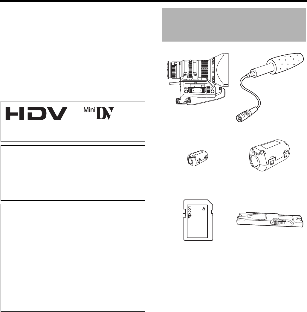
/ (Excluding the CHU/CHE
model)
Lens
XSee pages 10 and 33
Microphone
XSee page 33
Core Filter
For Viewfinder Cable
XSee page 34
Clamp Filters ×4
For DC (×2)/Earphone/
IEEE1394 Cable
XSee pages 12, 36 and 64
SD memory card
XSee page 34
Tripod base
(Provided only for U model)
XSee page 35

3
MAIN FEATURES
• GY-HD250/GY-HD251 records in HDV format or DV format.
DV format can record and play back SD (Standard Defini-
tion) video on Mini DV videocassettes.
HDV format can record and play back HD (High Definition)
video on Mini DV videocassettes.
There are two types of recording formats within HDV format.
HDV 720p (720 effective scan lines, progressive scan)
HDV 1080i (1080 effective scan lines, interlaced scan)
GY-HD250/GY-HD251 supports HDV 720p format. (HDV
720p)
HDV and are trademarks of Sony Corporation
and Victor Company of Japan, Limited.
• 24p mode shooting function
In HDV format, it records in 24p mode.
It uses a 2:3:2:3 pulldown when recording to tape and con-
verts the images to 60 frames. Component output is con-
verted to 60 frames during playback as well.
24p DV format video uses a 2:3:2:3 pulldown (24p Mode).
A 2:3:3:2 pulldown (24p Advanced Mode) is also supported.
It can shoot with the same number of frames as movie
film.
• Tapes recorded in the DVCAM format can only be played
back (simple playback).
Recording in the DVCAM format is not possible.
DVCAM is a registered trademark of Sony Corporation.
• 60 Hz/50 Hz HD or HDTV signals
Supports both 60 Hz/50 Hz HD or HDTV signals.
You can select this in a menu screen.
• Cross-convert video output
You can output converted video from the video output con-
nectors. You can select this in a menu screen.
• Outputs composite, component, Y/C separate and RGB
signals as analog video in DV format. Outputs composite
and component signals in HDV format.
• Features HD/SD SDI output terminals
Outputs serial digital HD and SD signals.
• Focus assist function
Enables easy and accurate focusing during shooting.
• User buttons added
Enables you to switch camera settings instantly to suit the
shooting conditions.
• External video signal input enabled
Records composite video signals from an external source.
• GENLOCK input terminal
Input BB (Black Burst) or HD Tri-sync signals. SC phase
and HD/SD H phase adjustments can be performed.
• Time code reader/generator
The built-in time code reader/generator can be used to
record the time code and user’s bits.
• Time code input/output terminal and slave lock function
Slave lock to an external time code generator connected
to the time code input terminal.
The time code output terminal outputs built-in time code
generator data.
• Built-in large 3.5" color LCD display
In addition to displaying the camera image and the play-
back image, the LCD monitor shows the status screens,
menu screens for settings, and alarm indications.
• Built-in monitor speaker for audio checking
The input audio can be monitored in recording or EE mode.
The playback sound can be monitored in the playback
mode. The speaker also outputs an alarm tone in case an
abnormal condition occurs in this device.
• Recording check function for convenient recording review
function
• Camera section designed with 3-CCD system for high-
quality picture
1/3" 3-CCD with 1,110,000 effective pixels employed. Dig-
ital signal processing for reproduction of HDV/DV high-
quality picture.
• Multi-Zone Auto Iris Detection Circuit
Multi-zone auto iris detection circuit ensures optimum iris
position even in back light conditions or when a bright sub-
ject moves in a frame.
• Safety Zone indication in viewfinder
• Zebra pattern video level indication in viewfinder
• Full Auto Shooting (FAS) function
Eliminates the need for troublesome switch or filter opera-
tions by automatically providing a wide range of compati-
bility with shooting conditions that change as you move
between indoors and outdoors or between bright and dark
locations.
• ND filters for 1/4ND, 1/16ND provided
• IEEE1394 connector
IEEE1394 connector (6-pin) provided. Enables transfer of
digital data to other equipment provided with IEEE1394
connector, such as a non-linear editing system. (Power
cannot be supplied.)
• 1/3" bayonet type lens
• Built-in color bars (ARIB (multi-format color bars), SMPTE/
EBU type)
• Shutter speeds and menus can be selected using a dial,
making it very easy to use.
• Variable scan shutter
There is no flicker when shooting computer screens and
other non-NTSC/PAL format screens.
•Slow shutter
Makes it possible to brightly shoot video of dark subjects
with little motion by accumulating the images.
• Backup recording function
Continuous extended recording is possible by connecting
to HDV/DV devices.
• Connect to KA-HD250 Studio Kit and use as a studio cam-
era.

4
CONTENTS
ACCESSORIES . . . . . . . . . . . . . . . . . . . . . . . . . . . . . . . . . 2
MAIN FEATURES . . . . . . . . . . . . . . . . . . . . . . . . . . . . . . . . 3
INTRODUCTION
Precautions for Proper Use . . . . . . . . . . . . . . . . . . . . . . . . . 6
Routine and Periodical Maintenance . . . . . . . . . . . . . . . . . .7
Precautions for Use of Head Cleaning Tape . . . . . . . . . . . . 7
Battery Pack to be Used . . . . . . . . . . . . . . . . . . . . . . . . . . . 8
Videocassette to be Used . . . . . . . . . . . . . . . . . . . . . . . . . . 8
For recording and storing videotapes in the best condition
. . . 8
Condensation . . . . . . . . . . . . . . . . . . . . . . . . . . . . . . . . . . . 9
Characteristic CCD Phenomena . . . . . . . . . . . . . . . . . . . . . 9
CONTROLS, INDICATORS AND
CONNECTORS
ZOOM Lens . . . . . . . . . . . . . . . . . . . . . . . . . . . . . . . . . . . .10
Front Section . . . . . . . . . . . . . . . . . . . . . . . . . . . . . . . . . . . 11
Rear Section . . . . . . . . . . . . . . . . . . . . . . . . . . . . . . . . . . . 12
LCD Door . . . . . . . . . . . . . . . . . . . . . . . . . . . . . . . . . . . . . 13
Right Side Section . . . . . . . . . . . . . . . . . . . . . . . . . . . . . . .14
Left Side Section . . . . . . . . . . . . . . . . . . . . . . . . . . . . . . . . 16
Top Section . . . . . . . . . . . . . . . . . . . . . . . . . . . . . . . . . . . . 18
Recording and Image Output Formats . . . . . . . . . . . . . . .20
Indications on the LCD Monitor and in the Viewfinder . . . . 22
Status Screens . . . . . . . . . . . . . . . . . . . . . . . . . . . . . . .22
Status Screens in the Camera Mode . . . . . . . . . . . . . . 23
Status Screen in VTR MODE . . . . . . . . . . . . . . . . . . . .28
Magnified Status Indications on the LCD Monitor. . . . . 29
Auto White Balance Indication (Camera mode only)
. . . .30
Menu Setting Screen . . . . . . . . . . . . . . . . . . . . . . . . . . 30
Alarm Message Display . . . . . . . . . . . . . . . . . . . . . . . . 30
Safety Zone Indication (Camera mode only) . . . . . . . . 30
Switching between the LCD Screen and
Viewfinder Display. . . . . . . . . . . . . . . . . . . . . . . . . .31
PREPARATIONS
Basic System . . . . . . . . . . . . . . . . . . . . . . . . . . . . . . . . . . . 32
Attaching the Zoom Lens . . . . . . . . . . . . . . . . . . . . . . . . . 33
Attaching the Microphone (Provided) . . . . . . . . . . . . . . . . 33
How to Attach the Viewfinder . . . . . . . . . . . . . . . . . . . . . .33
Inserting an SD Memory Card . . . . . . . . . . . . . . . . . . . . . . 34
Inserting an SD Memory Card . . . . . . . . . . . . . . . . . . . 34
Taking out the SD memory card . . . . . . . . . . . . . . . . . .34
About SD Memory Cards . . . . . . . . . . . . . . . . . . . . . . . 34
Attaching the Tripod Base (Provided only for U model)
. . . . . 35
AC Operation . . . . . . . . . . . . . . . . . . . . . . . . . . . . . . . . . . . 36
Charging the Built-in Battery . . . . . . . . . . . . . . . . . . . . .36
Battery Operation . . . . . . . . . . . . . . . . . . . . . . . . . . . . . . . .37
Attaching the Battery. . . . . . . . . . . . . . . . . . . . . . . . . . .37
Removing the Battery . . . . . . . . . . . . . . . . . . . . . . . . . .37
Precautions for the Battery Operation. . . . . . . . . . . . . .38
Remaining Battery Power Display . . . . . . . . . . . . . . . .38
Operating Time with Battery Pack . . . . . . . . . . . . . . . .38
Precautions for the Battery Pack . . . . . . . . . . . . . . . . .38
Recharging . . . . . . . . . . . . . . . . . . . . . . . . . . . . . . . . . .38
PREPARATIONS FOR OPERATION
Turning the Power ON . . . . . . . . . . . . . . . . . . . . . . . . . . . .39
Turning the Power ON . . . . . . . . . . . . . . . . . . . . . . . . .39
Turning the Power OFF . . . . . . . . . . . . . . . . . . . . . . . .39
Loading/Unloading the Cassette . . . . . . . . . . . . . . . . . . . .40
Cassette Loading . . . . . . . . . . . . . . . . . . . . . . . . . . . . .40
Unloading the Cassette. . . . . . . . . . . . . . . . . . . . . . . . .40
Setting and Displaying the Date and Time . . . . . . . . . . . .41
Setting the Date and Time Style . . . . . . . . . . . . . . . . . .41
Setting the Date and Time . . . . . . . . . . . . . . . . . . . . . .42
Displaying the Time and Date on the Screen . . . . . . . .42
Displaying Time Code . . . . . . . . . . . . . . . . . . . . . . . . . . . .43
Displayed Time Code/User’s Bit . . . . . . . . . . . . . . . . . .43
Time code input entered the IEEE1394 connector . . . .43
Presetting and Recording of Time Code . . . . . . . . . . . . . .44
Setting. . . . . . . . . . . . . . . . . . . . . . . . . . . . . . . . . . . . . .44
Presetting time code data . . . . . . . . . . . . . . . . . . . . . . .45
Presetting user’s bit data . . . . . . . . . . . . . . . . . . . . . . .45
Zero-resetting the Time Code or User’s Bit Data . . . . .45
Presetting the Time Code from the LCD Screen . . . . . . . .46
Recording Time Codes in Continuation of
Time Codes Recorded on Tape . . . . . . . . . . . . . . .47
Playing Back Time Code . . . . . . . . . . . . . . . . . . . . . . . . . .47
Synchronizing with the Time Code of
the IEEE1394 (DV)-Connected Master Unit . . . . . .48
Synchronizing with an External Time Code Generator . . .49
Screen Adjustment . . . . . . . . . . . . . . . . . . . . . . . . . . . . . .50
Viewfinder Adjustment . . . . . . . . . . . . . . . . . . . . . . . . . . . .50
Back Focus Adjustment . . . . . . . . . . . . . . . . . . . . . . . . . . .51
White Balance Adjustment . . . . . . . . . . . . . . . . . . . . . . . . .52
White Balance Adjustment . . . . . . . . . . . . . . . . . . . . . .52
Full Auto White Balance (FAW) . . . . . . . . . . . . . . . . . .52
White Shading Adjustment . . . . . . . . . . . . . . . . . . . . . . . .53
SETTING AND ADJUSTMENTS BEFORE
SHOOTING
Setting the Video Format . . . . . . . . . . . . . . . . . . . . . . . . . .54
Setting the FRAME RATE Item. . . . . . . . . . . . . . . . . . .54
Camera Settings . . . . . . . . . . . . . . . . . . . . . . . . . . . . . . . .55
Screen Size (4:3/16:9) Mode Selection . . . . . . . . . . . . . . .55
Audio Input Signal Selection . . . . . . . . . . . . . . . . . . . . . . .56
Selecting the CH-2 channel input connector. . . . . . . . .56
Selecting the audio signal input . . . . . . . . . . . . . . . . . .56

5
Adjusting Audio during Recording . . . . . . . . . . . . . . . . 56
Monitoring Audio during Recording . . . . . . . . . . . . . . .57
SHOOTING OPERATION
Basic Recording Operation . . . . . . . . . . . . . . . . . . . . . . . . 58
If the Record-Standby Mode Continues . . . . . . . . . . . . 59
Checking Recorded Contents in Record-Standby Mode
(Recording Check Function) . . . . . . . . . . . . . . . . . . 59
HEADER REC Function . . . . . . . . . . . . . . . . . . . . . . . . . . 60
PLAYBACK MODE
Playback Procedure . . . . . . . . . . . . . . . . . . . . . . . . . . . . . 62
Fast-Forward, Rewind . . . . . . . . . . . . . . . . . . . . . . . . . . . .62
Search . . . . . . . . . . . . . . . . . . . . . . . . . . . . . . . . . . . . . . . .62
Outputting Audio . . . . . . . . . . . . . . . . . . . . . . . . . . . . . . . . 63
USING EXTERNAL COMPONENTS
Connecting the Video Signal Cables . . . . . . . . . . . . . . . . . 64
Connecting the IEEE1394 Cable . . . . . . . . . . . . . . . . .64
Recording Composite Video Signals from
an External Device . . . . . . . . . . . . . . . . . . . . . . . . . 65
Using GENLOCK Functions . . . . . . . . . . . . . . . . . . . . . . . 66
Dubbing with AV Devices . . . . . . . . . . . . . . . . . . . . . . . . . 67
HDV/DV Dubbing . . . . . . . . . . . . . . . . . . . . . . . . . . . . . . .68
Backup Recording . . . . . . . . . . . . . . . . . . . . . . . . . . . . . . . 70
Connect a Remote Control Unit (RM-LP55/RM-LP57) . . . 71
MENU SCREENS
Menu Screen Configuration . . . . . . . . . . . . . . . . . . . . . . . . 73
Setting Menu Screens . . . . . . . . . . . . . . . . . . . . . . . . . . . .75
TOP MENU Screen . . . . . . . . . . . . . . . . . . . . . . . . . . . . . .76
VIDEO FORMAT[1/2] Menu Screen . . . . . . . . . . . . . . . . .77
VIDEO FORMAT[2/2] Menu Screen . . . . . . . . . . . . . . . . .79
CAMERA OPERATION Menu Screen . . . . . . . . . . . . . . . . 80
CAMERA PROCESS[1/2] Menu Screen . . . . . . . . . . . . . . 81
CAMERA PROCESS[2/2] Menu Screen . . . . . . . . . . . . . . 82
ADVANCED PROCESS Menu Screen . . . . . . . . . . . . . . . 83
COLOR MATRIX ADJUST Menu Screen . . . . . . . . . . . . . 84
SKIN COLOR ADJUST Menu Screen . . . . . . . . . . . . . . . .84
WHITE BALANCE Menu Screen . . . . . . . . . . . . . . . . . . . . 85
SWITCH MODE Menu Screen . . . . . . . . . . . . . . . . . . . . . 86
AUDIO/MIC[1/2] Menu Screen . . . . . . . . . . . . . . . . . . . . . 87
AUDIO/MIC[2/2] Menu Screen . . . . . . . . . . . . . . . . . . . . . 88
LCD/VF[1/4] Menu Screen . . . . . . . . . . . . . . . . . . . . . . . .89
LCD/VF[2/4] Menu Screen . . . . . . . . . . . . . . . . . . . . . . . .90
LCD/VF[3/4] Menu Screen . . . . . . . . . . . . . . . . . . . . . . . .91
LCD/VF[4/4] Menu Screen . . . . . . . . . . . . . . . . . . . . . . . .92
TC/UB/CLOCK Menu Screen . . . . . . . . . . . . . . . . . . . . . . 93
HEADER REC Menu Screen . . . . . . . . . . . . . . . . . . . . . . . 94
TIME/DATE Menu Screen . . . . . . . . . . . . . . . . . . . . . . . . . 95
OTHERS[1/2] Menu Screen . . . . . . . . . . . . . . . . . . . . . . .96
OTHERS[2/2] Menu Screen . . . . . . . . . . . . . . . . . . . . . . .97
GENLOCK Menu Screen . . . . . . . . . . . . . . . . . . . . . . . . . .99
FILE MANAGE Menu Screen . . . . . . . . . . . . . . . . . . . . .100
Displaying the FILE MANAGE menu screen . . . . . . .100
Loading a menu settings file . . . . . . . . . . . . . . . . . . . .100
Saving settings . . . . . . . . . . . . . . . . . . . . . . . . . . . . . .101
Resetting the menu settings to the factory settings
. . . .102
Initializing (formatting) an SD memory card . . . . . . . .102
FEATURES OF THE CAMERA SECTION
How to Use Skin Detail . . . . . . . . . . . . . . . . . . . . . . . . . .103
Outputting Color Bars . . . . . . . . . . . . . . . . . . . . . . . . . . .105
OTHERS
Warnings and Responses . . . . . . . . . . . . . . . . . . . . . . . .106
Troubleshooting . . . . . . . . . . . . . . . . . . . . . . . . . . . . . . . .110
How to Display the Hour Meter . . . . . . . . . . . . . . . . . . . .111
Specifications . . . . . . . . . . . . . . . . . . . . . . . . . . . . . . . . . .112
EXTERNAL DIMENSIONS . . . . . . . . . . . . . . . . . . . . .113

6
INTRODUCTION
Precautions for Proper
Use
• Supply voltage
Make sure that the power is between 11 V and 15 V DC. If
the power voltage is too low, abnormal color and
increased noise may occur.
• Allowable ambient temperature and humidity
Be sure to use this device within the allowable tempera-
ture range of 0°C to 40°C and a relative humidity of 30% to
80%. Using this device at a temperature or humidity out-
side the allowable ranges could result not only in malfunc-
tion but the impact on the CCD elements could be serious
as small white spots may be generated.
• Strong electromagnetic waves or magnetism
Noise may appear in the picture or audio and/or the colors
may be incorrect if the camera is used near a radio or tele-
vision transmitting antenna, in places where strong mag-
netic fields are generated by transformers, motors, etc., or
near devices emitting radio waves, such as transceivers or
cellular phones.
• Use of wireless microphone near the camera
When a wireless microphone or wireless microphone
tuner is used near the camera during recording, the tuner
could pick up noise.
• Avoid using or placing this device in places;
• subject to extreme heat or cold;
• with excessive dirt or dust;
• with high humidity or moisture;
• subject to smoke or vapour such as near a cooking
stove;
• subject to strong vibrations or on an unstable surface;
• also do not leave this device for long hours in a parked
car under direct sunlight or near room heating equip-
ment.
• Do not leave this device where it is subject to radiation or
X-rays or where corrosive gasses occur.
• Protect this device from being splashed with water (espe-
cially when shooting in the rain).
• Protect this device from being wet when shooting on a
beach.
In addition, salt and sand may adhere to the camera body.
Be sure to clean the camera after use.
• Protect this device against penetration of dust when using
it in a place subject to sandy dust.
• Optical performance of lens
Due to the optical performance of the lens, color diver-
gence phenomena (magnification chromatic aberration)
may occur at the periphery of the image.
This is not a camera malfunction.
• Noise may appear in the viewfinder when switching
between the playback picture and the EE picture.
• Use this device in an upright position.
If placed on its side, heat release efficiency will deterio-
rate, adversely affecting the tape transport. Depending on
circumstances the tape may also be damaged.
•Vibrations
Colors may fail to appear and/or the image and sound
may be disturbed during VTR playback in locations sub-
jected to strong vibrations.
• Precautions for transportation
Do not drop or hit this device against a hard object.
• Remove the videocassette before transporting this device.
• Do not insert an object other than a videocassette in the
cassette insertion slot. Be sure to close the cassette cover
when this device is not to be used for a long period.
• Do not set the POWER switch to OFF or remove the
power cable during recording or playback. Otherwise the
tape may be damaged.
• The sensitivity level of the provided microphone is set
lower than the reference input (–60 dBs) setting.
• When this device is not in use, be sure to set the POWER
switch to OFF in order to reduce power consumption.
• Cleaning the body: Wipe body with a dry, soft cloth. To
prevent deformation of the body, etc. and to avoid opera-
tion hazards, do not allow volatile liquids such as benzine
and thinner to touch the body, and do not wipe it with a
cloth soaked in such a liquid. When it is extremely dirty,
soak the cloth in a solution of neutral detergent, wipe the
body with it, and then use a clean cloth to remove the
detergent.
• The camera may not show stable pictures in the period
immediately after the power is turned on, but this is not a
malfunction.
• A sound occurs when the built-in head cleaner that runs
when you load or eject a videocassette operates, but this
is not a malfunction.
• The LCD monitor and the viewfinder screen
The LCD monitor and the viewfinder screen are manufac-
tured using high-precision technology. Black spots may
appear on the LCD monitor and the viewfinder screen, or
red, blue, green and/or white spots may not turn off. How-
ever, this is not a malfunction and these spots are not
recorded on the tape.
• If you use this device continuously for a long period of
time, the characters displayed in the viewfinder may tem-
porarily remain on the screen. This is not recorded on the
tape. In addition, they are no longer displayed if you turn
the power off and then on again.
• If you use this device in a cold location, the images may
appear to lag on the screen, but this is not a malfunction.
This is not recorded on the tape.
• Do not insert fingers or foreign objects into the cassette
insertion slot as this may result in personal injury or dam-
age to the mechanism.
• To prevent damage to the connectors, use this device with
the connector covers on when you are not using the video/
audio signal output connectors.
CAUTION
• Do not point the lens or viewfinder directly at the sun or
other strong light source.
• Eye damage could result.
• If the lens or viewfinder is left pointed at the sun, rays
may collect inside this device and cause damage or a
fire.
• When carrying the camera, be sure to hold the carrying
handle. Holding the lens or viewfinder may result in
damage.
7
Routine and Periodical
Maintenance
The GY-HD250/GY-HD251 incorporates precision mechani-
cal parts, which will collect dirt, wear out and deteriorate as
this device is used. After this device has been used for a long
period even in a normal environment, the heads, drums and
tape transport mechanisms also collect dirt. Especially, dust
which penetrates the inside of the VTR section during out-
door use will promote the wear and deterioration of mechani-
cal parts by causing poor contact between tape and heads or
failing to maintain the video and audio quality at high levels.
To prevent wear and deterioration, clean the mechanical
parts using a head cleaning tape as routine maintenance.
However, cleaning with a head cleaning tape alone is not
enough for cleaning the entire tape transport mechanism, so
it is also recommended to apply periodical maintenance
(inspection) to prevent the sudden occurrence of failure. As
the replacement, adjustment and servicing of parts require
advanced skill and equipment, please consult the person in
charge of professional video equipment at your nearest JVC-
authorized service agent.
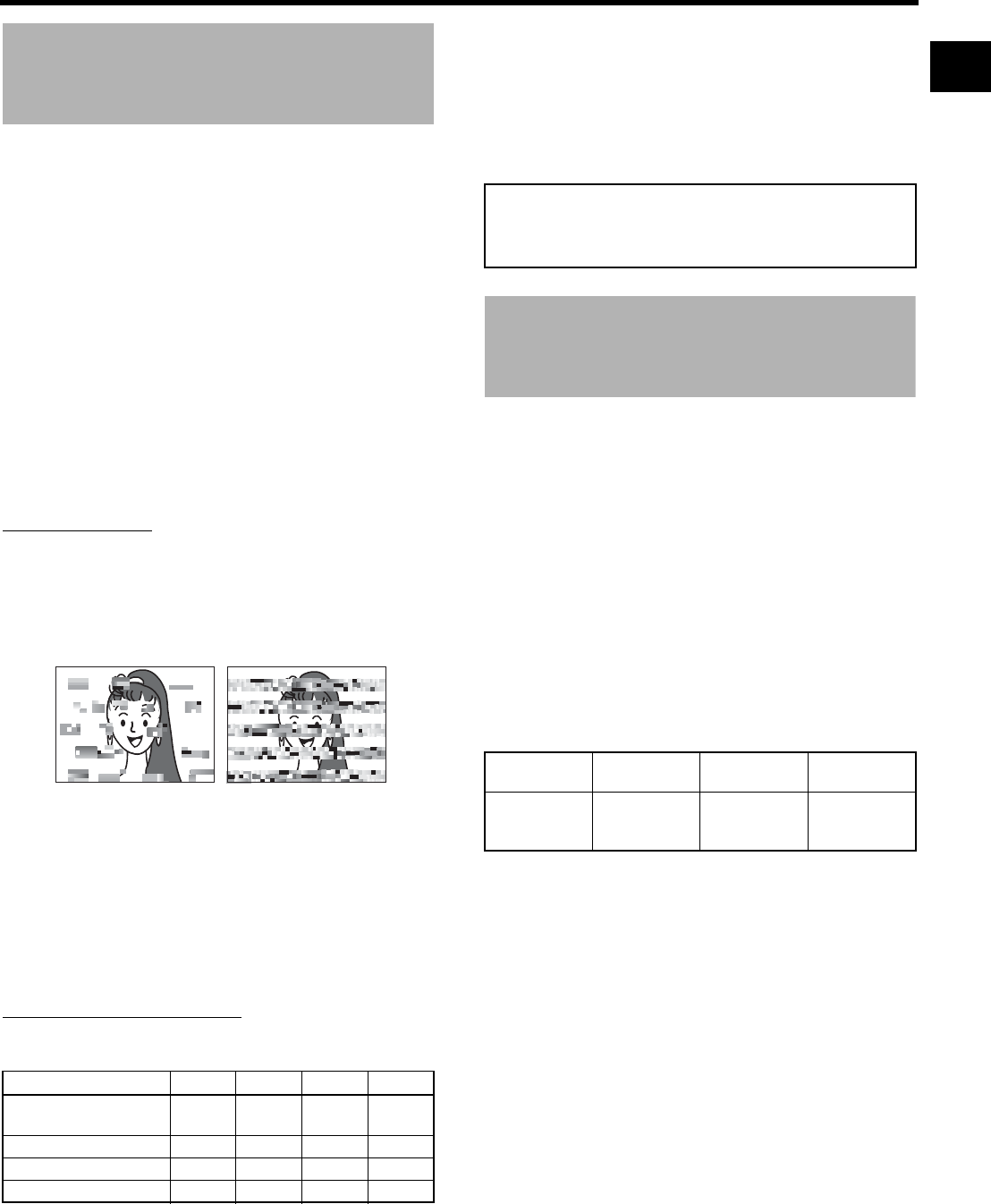
Head Cleaning
• To maintain beautiful pictures and sound, be sure to use a
head cleaning tape to clean the head periodically.
XSee “Precautions for Use of Head Cleaning Tape”. If
head cleaning is not performed periodically, a type of
mosaic noise called block noise may appear in the picture
or sound may be interrupted.
• Please use cleaning tape produced by JVC. Do not use
head cleaning tapes other than specified.
XSee “Precautions for Use of Head Cleaning Tape”
about how to use the head cleaning tape and precautions
for use of the head cleaning tape.
• When dust adheres to the heads, the warning message
“HEAD CLEANING REQUIRED!” is displayed on the LCD
monitor, and in the viewfinder during playback and record-
ing check using the RET button on the lens section.
Periodical Maintenance
Contents : Check or replace the following mechanical parts
according to the running time.
G: Clean, check and adjust.
E: Clean and check. Replace as required.
F: Replace.
• The maintenance contents vary depending on the operat-
ing environment and method. Therefore, the data in the
chart should be considered as a reference.
Time management
The accumulated running time of this device can be con-
firmed with the hour meter display (which shows the accu-
mulated drum and fan motor running time). XSee “How to
Display the Hour Meter” on page 111.
Precautions for Use of
Head Cleaning Tape
Please use cleaning tape produced by JVC.
Adhere to the following precautions when using the head
cleaning tape.
1. Insert the cleaning tape.
Press the PLAY/STILL button after the cleaning tape is
fully loaded.
The tape runs for 10 seconds at a time in the PLAY
mode. (The tape stops automatically and then this device
enters the STOP mode.)
2. Do not use the tape more than four times at the most for
each cleaning.
Use the following chart as a guide for periodical head
cleaning.
Note 1) When used in a low humidity environment, head
cleaning should be conducted at intervals half of
those given in the chart above.
Note 2) If an M-DV80 tape is used immediately after head
cleaning, the “HEAD CLEANING REQUIRED!”
indicator may remain on. In this case, let the tape
run as the indicator will turn off after the tape has
run for a while.
Note 3) Use the cleaning tape in the room temperature
(10°C to 35°C).
Note 4) The cleaning tape case contains instructions for
use of the cleaning tape. However, some of these
instructions differ from the contents of this sheet.
When using the cleaning tape, please follow the
instructions of this sheet.
Note 5) If the “HEAD CLEANING REQUIRED!” does not
disappear after repeated head cleanings, the
recording tape may be abnormal. Avoid excessive
repeated use of the head cleaning tape.
Usage Time 500H 1000H 1500H 2000H
Drum assembly (includ-
ing heads) GEEF
Tape guides, rollers GEEF
Belt gears HEEF
Drive parts HHE F
Block Noise
For consultations related to the maintenance planning or
cost, please contact the person in charge of professional
video equipment at your nearest JVC-authorized service
agent.
Running
Low
temperature
Room
temperature
High
temperature
Operating envi-
ronment
0°C to 10°C 10°C to 35°C 35°C to 40°C
Yardstick for
use of cleaning
tape
1 to 2 times ev-
ery 5 hours
1 to 2 times ev-
ery 20 to 30
hours
1 to 2 times ev-
ery 5 hours
INTRODUCTION
8
Battery Pack to be Used
The GY-HD250/GY-HD251 can use any of the following bat-
teries. (Factory setting)
U model: Anton Bauer battery
E model: IDX battery
Recommended batteries
U model: Dionic 90 (Anton Bauer)
E model: Endura-7 (IDX)
CAUTION
Use only the recommended batteries.
If a heavy battery is used, the battery may fall out depend-
ing on the way the HD camera recorder is used.
Videocassette to be Used
• Use JVC’s videocassette tapes marked with the A
symbol.
• Mini DV videocassette : M-DV63HD
M-DV63PROHD
* Do not use M-DV80.
• Videocassettes cannot be used upside down.
• Avoid storing a videocassette with its tape not being com-
pletely wound, as this may damage the tape. Rewind it to
the beginning before placing a cassette into storage.
• Store videocassettes in a place with little humidity and
good ventilation where mould does not form.
• After a videocassette tape has been used repeatedly, it
becomes unable to maintain full performance due to an
increase in noise caused by dropouts, etc. Do not continue
to use a dirty or damaged tape, as this will reduce the
rotary head life.
• Videocassette tapes with the A symbol are provided
with a switch on the back to prevent accidental erasure.
• Slide the switch to SAVE to protect the required recording
in the tape from being overwritten.
• To record on the tape, slide the switch to REC.
For recording and storing
videotapes in the best con-
dition
Observe the following instructions for the best recording and
storage of videotapes.
• Take care of the conditions of handling videotapes. It is
recommended that you record and store videotapes in the
environment below.
• Do not leave the videotapes neglected for a long period. If
videotapes are left wound for a long period of time, it may
result in distortion of the tape. Also it may cause tape-to-
tape adhesion (known as blocking). It is recommended
that videotapes be unspooled and rewound once a year
for refreshing.
• When tapes are not in use, store them in cases and on
end. Storage cases protect videotapes from humidity, dust
and ultraviolet light. Keep tapes in cases and do not store
them lying flat. When housed in a horizontal position, pres-
sure from other tapes can cause distortions and deforma-
tions of the tape edges.
Switch
Recording
Storage
Short period
(Up to 10
years)
Long period
(Over 10
years)
Temperature 17°C to 25°C 15°C to 23°C 15°C to 19°C
Humidity 30% to 70% 40% to 55% 25% to 35%
Hourly tempera-
ture change
Less than
10°C HH
Hourly humidity
change
Less than
10% HH
9
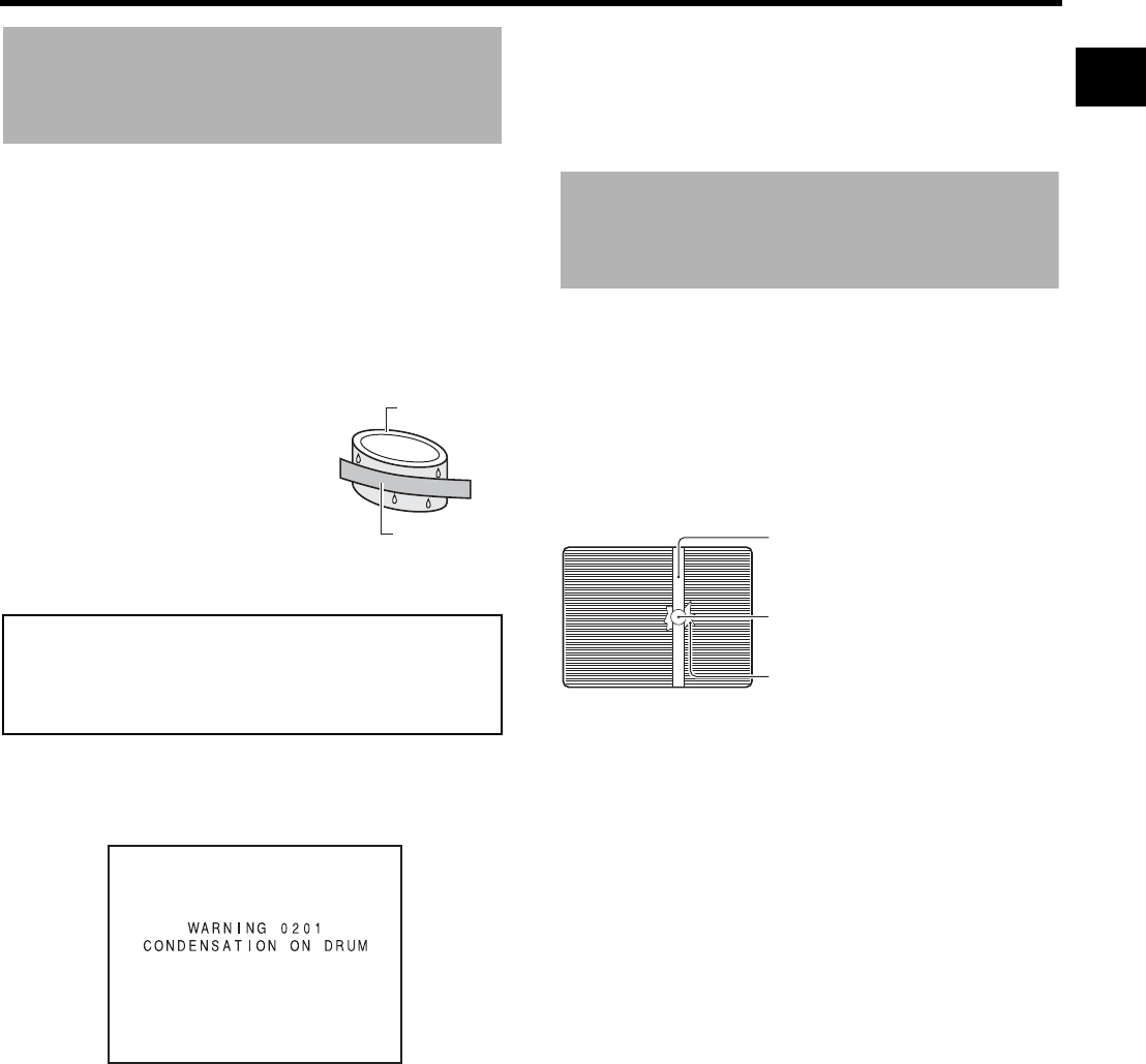
Condensation
• If this device has been cooled down in a cold place and is
then carried to a warm place, the moisture contained in
the warm air may adhere to the head drum or tape guides
and be cooled into water droplets. This phenomenon is
referred to as condensation (dew). When this occurs, the
head drum and tape guides are covered with droplets
allowing the tape to be stuck to them, leading to tape dam-
age.
• Condensation occurs in the following cases:
• When this device is suddenly
moved from a cold place to a
warm place.
• When a room heater has just
started or when this device is
exposed directly to cold air from
an air conditioner.
• When this device is placed in a
very humid place.
• “CONDENSATION ON DRUM” is displayed on the LCD
monitor and in the viewfinder when condensation occurs
in this device.
Keep the power on until the warning message disappears.
If the power is turned off while the warning message is dis-
played, condensation may remain in the device even if the
warning message is not displayed. Wait until this device is
completely dry before using.
• Pay attention to condensation even before the condensa-
tion indication appears.
As condensation forms gradually, the condensation indica-
tion may not appear for the first 10-15 minutes after con-
densation has formed inside.
In an extremely cold place, the condensation could freeze
and turn into frost. In such a case, it takes an additional 2-
3 hours for the frost to first melt into condensation and
then to be dissolved.
• To prevent condensation
When moving this device from one place to another where
the temperatures are greatly deferent, first remove the vid-
eocassette, place this device in a tightly sealed vinyl bag,
and then move it to a new environment.
To ensure no condensation occurs, allow the temperature
of this device in the bag to reach that of the new environ-
ment before using it.
Characteristic CCD Phe-
nomena
Smear and Blooming
Due to the physical structure of a CCD it is possible to induce
vertical streaking (called “smear”) when shooting an
extremely bright light source. Another effect is the expansion
of light around a bright light or object (called “blooming”).
The CCD employed in this device is characterized by induc-
ing very little smear or blooming. Nevertheless, please take
note that smear or blooming may be induced when shooting
a bright light source.
Moire or Aliasing
Shooting stripes or fine patterns may cause a jagged effect
or a banding in fine mesh patterns.
White dots
High temperatures can cause CCD sensor pixels to produce
the effect of white dots in the image. This condition is con-
spicuous especially when gain is applied.
This is a characteristic of the charged-coupled device (CCD).
As far as possible, use this device under conditions where
the temperature of this device does not increase.
Do not leave the videocassette inserted when moving the
camera under conditions where the temperature environ-
ment changes.
After moving this device, do not use until the internal parts
have stabilized.
Head drum
Video tape Smear
Vertical pale streaking appearing at high
luminous object
High luminous object
(Electric light, sunlight, etc.)
Blooming
Blurring in highlight
Monitor screen
10
CONTROLS, INDICATORS AND CONNECTORS
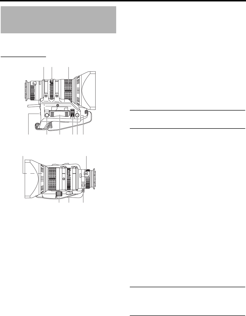
ZOOM Lens
The zoom lens is not provided with the GY-HD250CHU or
the GY-HD251CHE.
Th16 × 5.5BRMU
1FOCUS ring
Manual focus ring.
2ZOOM lever/ring
This is the manual zoom ring equipped with a zoom lever.
To adjust the zoom manually, turn the zoom mode knob b
to position “M”.
3IRIS ring
Manual iris ring. To activate the auto iris feature, set the
Iris Mode switch 7 to “A”.
4[VTR] VTR trigger button
To start/stop shooting.
5[RET] Return video button
You can only monitor the return video signal from the VTR
on the viewfinder, LCD monitor and video signal connector
while this button is pressed.
When the camera control unit is connected, you can moni-
tor the return video signal on the viewfinder while this but-
ton is pressed. You cannot monitor on the LCD monitor or
video output terminal.
When you set the LENS RET item to “FOCUS ASSIST” in
the SWITCH MODE menu screen, you can use this button
as the FOCUS ASSIST button.
XSee page 86.
6ZOOM servo control lever
To operate the servo zoom feature with this lever, set the
ZOOM knob b to “S”.
• Pressing the “W” section of this lever increases the
angle of the lens for a wider shooting angle.
• Pressing the “T” section of this lever narrows the lens
angle perspective for telephoto shots.
• Pushing harder changes the speed of the zoom.
7IRIS mode switch
8Momentary auto iris button
When the IRIS mode switch 7 is at “M”, pushing this but-
ton activates the Auto Iris Function while it is held down
only.
9[S] IRIS speed adjusting control
For adjusting the iris operation speed.
MEMO
If the speed becomes too fast, hunting may occur. To avoid
the phenomena described above, perform adjustment
again.
0FILTER thread
Protect the lens with a clear filter or UV filter by screwing
the filter onto the thread inside the lens hood from the
front.
Other filters can be used for various effects.
aZOOM servo connector
Connect an optional zoom servo unit here.
b[ZOOM] ZOOM mode knob
cBACK FOCUS ring/fixing screw
For back focus adjustment only. Secure with the screw
knob after adjustment. XSee “Back Focus Adjustment”
on page 51.
dMacro focusing ring (for close-up shooting)
By rotating this ring in the direction of the arrow, close-up
shooting of very small objects becomes possible.
Normal focus adjustment and zooming are not available in
the macro mode.
To shoot images in the macro mode, set the focus ring 1
to the infinite position (∞) and the zoom ring 2 to the max-
imum wide-angle position. To adjust the focus of the
macro image, rotate this ring in the direction of the arrow
until the object is focused.
CAUTION
• The back-focus knob is located close to the macro ring,
be careful not to mistake the back-focus knob for the
macro ring.
• After the required operation, be sure to return the macro
focusing ring to the normal position.
XSee “Attaching the Zoom Lens” on page 33.
XSee “Back Focus Adjustment” on page 51.
M
RET
WT
A
MACRO
32
456789
1
0
abc
d
A : Activates the auto iris feature.
M : Allows manual iris control.
S : Servo zoom mode. Allows operation by the zoom
servo control lever 6.
M : Manual zoom mode. Allows zoom control by the
zoom lever/ring 2.
11
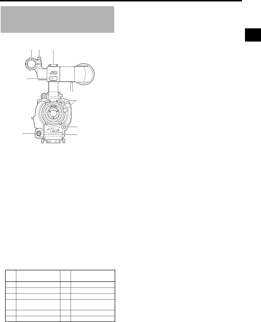
Front Section
1Shoe
Makes it possible to mount separately sold lights and
accessories.
2Knob
This is the mounting knob for the microphone holder 3.
3Microphone holder
Makes it possible to attach the provided microphone or a
separately sold microphone.
XSee “Attaching the Microphone (Provided)”
on page 33.
4Front tally lamp
This lamp lights up when the GY-HD250/GY-HD251 enters
the record mode. It blinks during the transition to the
record mode.
When the tape has run out, or the VTR enters the warning
mode, it blinks quickly.
• Use the FRONT TALLY item on the OTHERS[1/2] menu
screen to select whether or not the lamp should light
and the lighting pattern.
XSee page 96.
5[LENS] Lens control connector
Connect 12-pin lens control cable from lens here.
6[ZEBRA] Zebra switch
When this switch is ON, a zebra pattern is imposed on the
viewfinder or LCD areas having luminance levels in accor-
dance with the menu settings made for the video signal.
This pattern can be used as a reference for manual adjust-
ment of the lens iris. Zebra patterns are also displayed
during color bar display when this switch is set to ON.
• The default value is 70% - 80%. The luminance level
can be changed with the ZEBRA setting in the LCD/
VF[1/4] menu screen.
XSeepage89.
While this switch is pressed to the SKIN AREA side, the
color tone areas specified with the SKIN COLOR ADJUST
item on the ADVANCED PROCESS menu are indicated in
the viewfinder. The switch returns to the OFF position
when released.
XSee “How to Use Skin Detail” on pages 103 and 104.
* The Skin Detail color tone areas are not indicated while
the color bar or VTR playback picture is shown in the
viewfinder or on the LCD monitor.
7[AWB] Auto white balance button
When the WHT.BAL switch c on page 15 is set to A or B
and you press this button, the white balance is automati-
cally adjusted.
* It is not activated in preset, full auto shooting, full auto
white balance and color bar modes.
XSee “White Balance Adjustment” on page 52.
8Lens mounting ring/Lens lock lever
Hold the lens and use the lever to turn the ring anticlock-
wise to release lens.
To mount lens make sure the lens guide pin fits well, and
then turn the ring clockwise until firm.
XSee “Attaching the Zoom Lens” on page 33.
Pin
No. Function Pin
No. Function
1 Return switch 7 Iris position
2 VTR trigger 8 IRIS A/R INPUT
3 GND 9 EXTENDER position
4
Lens AUTO/MANU con-
trol
10 ZOOM position
5 IRIS control 11 –
6 +12V DC 12 –
32 1
4
5
8
7
6
CONTROLS, INDICATORS AND CONNECTORS
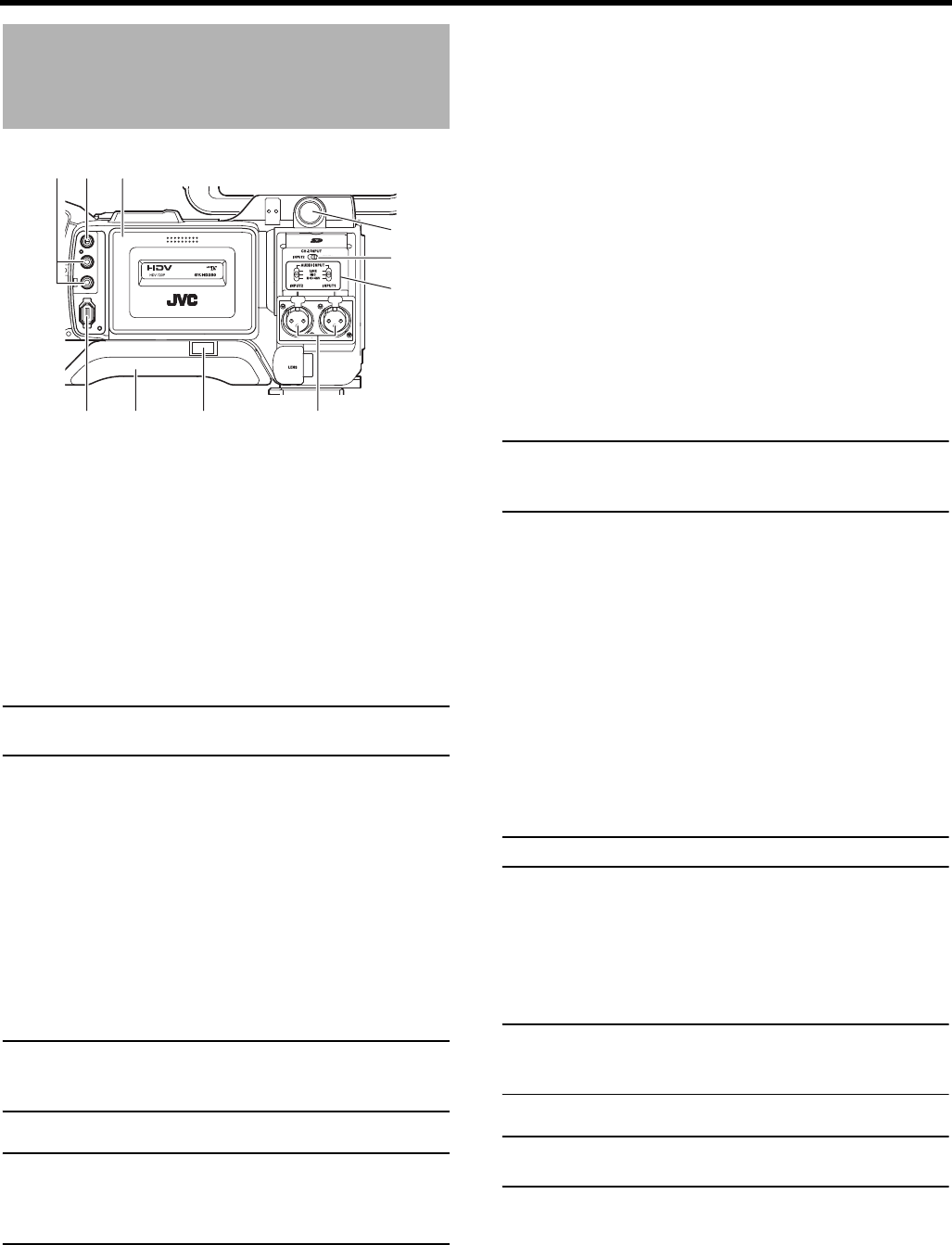
12
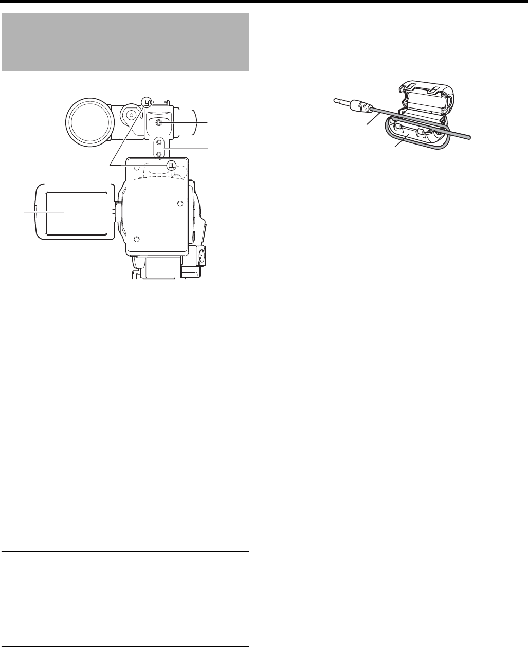
Rear Section
1Back tally lamp
This lamp lights up when the GY-HD250/GY-HD251 enters
the record mode. It blinks during the transition to the
record mode.
When the tape has run out, or the VTR enters the warning
mode, it blinks quickly.
• Use the BACK TALLY item on the OTHERS[1/2] menu
screen to select whether or not the lamp should light
and the lighting pattern.
XSee page 96.
2[PHONES] Earphone jack
This is a stereo mini-jack for connecting an earphone for
audio monitoring. Plug in an earphone or headphone with
a 3.5 mm diameter plug. The earphone can also be used
to monitor alarm tones in accordance with the circum-
stances.
The audio channel to be output is selected with the AUDIO
MONITOR item on the AUDIO/MIC[2/2] menu screen and
MONITOR SELECT switch d on page 19.
The audio output level is adjusted with the Audio monitor
volume control 3 on page 14.
MEMO
• The volume of the alarm sound is set with the ALARM
VR LEVEL item on the OTHERS[1/2] menu screen.
• When using a stereotype jack and stereo sound should
be output, the following setting should be performed.
Set the MONITOR SELECT switch d on page 19 to
BOTH.
Set the AUDIO MONITOR item on the AUDIO/MIC[2/2]
menu screen to STEREO.
Connecting the Earphone Cable
To reduce the emission of unwanted radio waves, be sure to
attach the provided clamp filter as shown in the figure below.
• Attach the clamp filter as close to this device as possible,
as shown in the figure.
3Shoulder belt hooks
Allows you to attach a separately sold shoulder belt.
4LCD monitor
Shows a color camera image or the VTR playback picture.
It is also used for displaying the following:
• Menu Setting screens
• Characters showing the whether the GY-HD250/GY-
HD251 is set to shooting mode or VTR playback mode
• Date and time and time code
• Audio level meter
• Warning indications, etc.
XSee page 22.
1
2
3
4
Earphone cable
Clamp filter
13
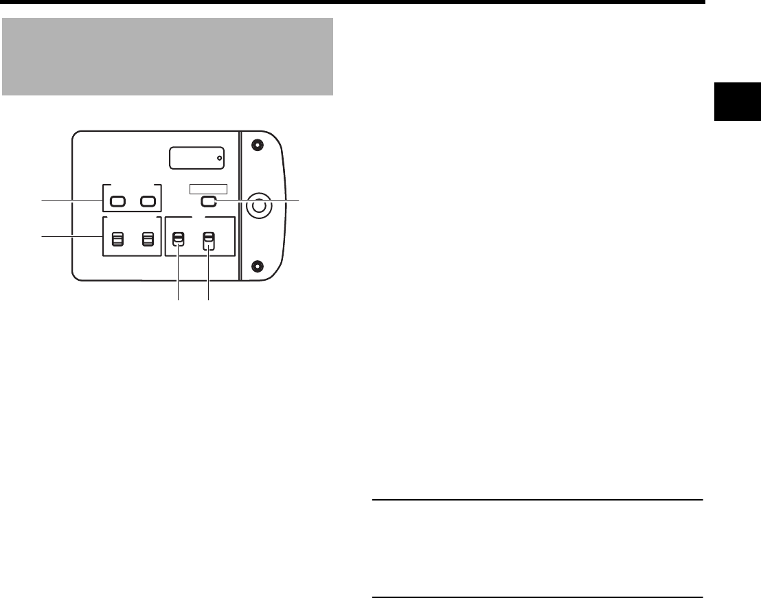
LCD Door
1[LCD BRIGHT +/–] LCD brightness +/– button
This button is for adjusting the brightness of the LCD mon-
itor display.
• Pushing the button in the + direction makes the monitor
brighter.
• Pushing the button in the – direction makes the monitor
darker.
• Pushing the +/– buttons simultaneously returns the set-
ting to the standard setting.
2[CH-1/CH-2 AUDIO SELECT] CH-1/CH-2 audio selector
switch
Selects the method of adjusting the CH-1 and CH-2 audio
channel audio levels.
3[TC DISPLAY] TC/UB display switch
Selects the contents displayed on the TC counter of the
LCD monitor or in the viewfinder. (This switch works when
the TC/UB item on the LCD/VF[3/4] menu screen is set to
ON.)
4[TC GENE.] Time code generator setting switch
Switch for setting the time code generator to preset mode
or regeneration mode. It is also used to select the time
code run mode when the preset mode is selected.
MEMO
• This switch is enabled when TCG SOURCE on the TC/
UB/CLOCK menu screen is set to INTERNAL.
• Preset of time code and user’s bits is performed on the
TC/UB/CLOCK menu.
XSee page 44.
XSee “TC/UB/CLOCK Menu Screen” on page 93.
5[CAM/VTR] Camera/VTR mode switch button
Each time you press this button, the mode switches
between camera mode and VTR mode.
When you do this, the VTR indicator f on page 19 dis-
plays the following statuses.
While the mode is being switched: Flashing
In VTR mode : Lit
In camera mode : Off
• Select the Camera mode to record the camera image.
• Select the VTR mode to playback VTR or to input the
HDV/DV signal from the IEEE1394 connector 0 on
page 16.
• When the power is turned on, the mode becomes the
Camera mode.
AUTO : The audio level is automatically adjusted
according to the input level. When excessive
audio is input, the limiter works to suppress
the audio level.
The “AUTO” LED in the CH-1/CH-2 AUDIO
LEVEL area f on page 15 lights.
MANU : Allows you to adjust the audio levels using
the CH-1/CH-2 AUDIO LEVEL volume con-
trols f on page 15.
Set AUDIO LIMITER on the AUDIO/MIC[1/2]
menu screen to use limiter functions when
excessive audio is input.
XSee “AUDIO LIMITER” on page 87.
TC : Set to this position to display time code values.
UB : Set to this position to display the user’s bits values.
CH-2
CH-1
-
+
AUDIO SELECT
MANU
AUTO
TC
LCD BRIGHT
DISPLAY
TC
UB
FREE
REGEN
GENE.
REC
CAM/VTR
5
1
2
34
FREE : The preset mode is selected, and the time
code run mode becomes the FREE run
mode.
Set to this position to record with the time
code or user’s bits set anew (preset). In this
setting, the time code always operates in the
run mode.
* If this setting is used when recording
scenes one after another, the time codes
become discontinuous at the transition
points between scenes.
REC : The preset mode is selected, and the time
code run mode becomes the REC run mode.
Set to this position to record with the time
code or user’s bits set anew (preset). The
time code operates in the run mode during
recording only. If this setting is used when
recording scenes one after another, the time
codes are recorded as continuous time
codes.
REGEN : Regeneration mode, in which this device
reads existing time codes on the tape and
records time codes in continuation of the
existing ones. Set to this position when you
want to add additional time codes to time
codes already recorded on the tape.
CONTROLS, INDICATORS AND CONNECTORS
14
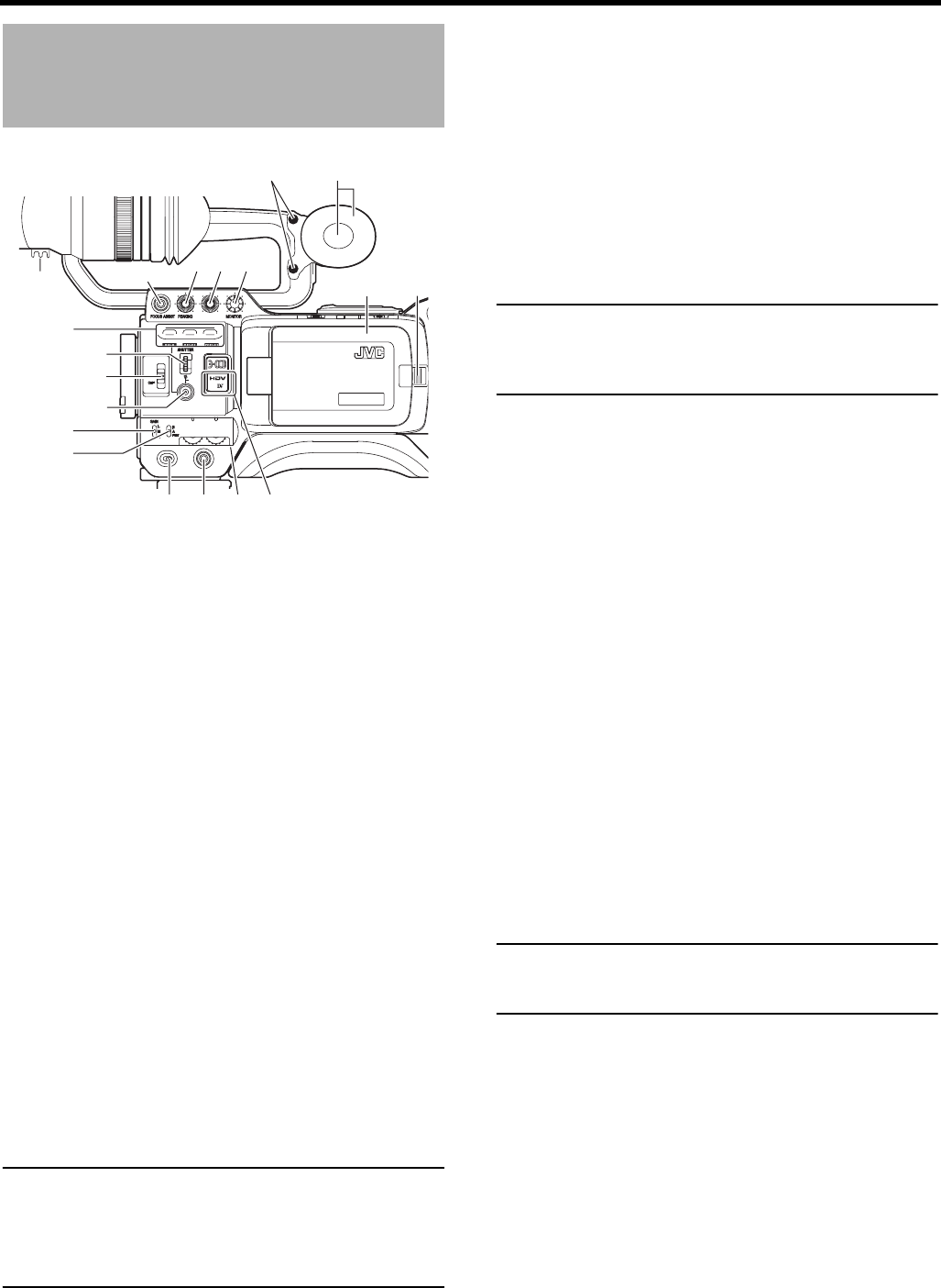
Right Side Section
1Monitoring speaker (Cheek pad)
• In the Camera mode, the input sound can be EE moni-
tored.
In the VTR mode, the speaker outputs the VTR play-
back sound. In the VTR mode, the HDV/DV input sound
can be EE monitored.
The sound to be output is selected with the MONITOR
SELECT switch d on page 19.
• The sound level is adjusted with the MONITOR sound
level volume 3. This speaker also outputs various
warning sounds superimposed on other sound.
XSee “Alarm Sound” on page 109.
2Cheek pad set screw
Screw for adjusting the height of the cheek pad.
3[MONITOR] Audio monitor volume control
Adjusts the volume of the monitoring loudspeaker and ear-
phone.
4[VF BRIGHT] Viewfinder brightness adjustment
To adjust the brightness of the viewfinder.
XSee page 50.
5[PEAKING] Contour adjustment
To adjust the contours of the LCD monitor and viewfinder
image.
* When the Focus Assist function is running, this control
does not operate.
XSee page 50.
6[FOCUS ASSIST] Focus assist button
When you press this button during shooting, the area of
focus is displayed in blue, red or green, making it easy to
focus accurately.
MEMO
• When FOCUS ASSIST on the LCD/VF[1/4] menu screen is
set to ACCU-FOCUS and this button is pressed, ACCU
FOCUS functions with FOCUS ASSIST. This makes depth of
field shallower, making it easier to focus.
• This button has the same function as the FOCUS
ASSIST button 7 in the Top Section.
XSee “LCD/VF[1/4] Menu Screen” on page 89.
7Clamp
Attach the cable from the viewfinder here.
8[USER1/2/3] User buttons
You can assign camera functions to the USER1 - 3 but-
tons.
Use them to switch shooting conditions depending upon
the subject.
Set them using the USER1 - 3 items in the SWITCH
MODE menu screen.
XSee page 86.
Use this button to preset the time code.
XSee page 46.
MEMO
• The USER buttons work together with the menu settings.
• When a menu screen is being displayed, they also func-
tion as menu operation buttons. XSee “Setting Menu
Screens” on page 75.
9[SHUTTER] Shutter/Menu dial
• Every time this dial is pressed while in the normal
screen mode (when the menu screen is not displayed),
the shutter speed switches between on/off.
• When this dial is turned 1 click up or down in the normal
screen mode, the shutter speed indicator is shown for
about 3 seconds on the LCD monitor or in the view-
finder. The shutter speed is changed when this dial is
turned while the shutter speed indicator is shown.
XSeepage86.
• When this dial turned upward or downward while the
menu screen is displayed, the cursor (K) also moves
upward or downward to allow selection of items in the
menu. To change the setting value of the item, press
this dial. When the setting value starts blinking, turn this
dial upward or downward to change the setting.
XSee “Setting Menu Screens” on page 75.
0[ND FILTER] ND filter switch
Switches the built-in ND filter.
When you change this switch, the type of the new ND filter
is displayed in the LCD monitor or viewfinder.
CAUTION
If you switch the ND filter while shooting is in progress, the
picture may be disturbed or noise may occur in the audio.
XSee “Camera Settings” on page 55.
USER 3USER 2USER 1
STATUS
MENU
2
1
ND FILTER
REC
OFF
ON
POWER
WHT.BAL
AUTO
AUDIO
LEVEL
AUTO
CH-1 CH-2
VF BRIGHT
1
2
3
45
6
7
8
9
0
a
b
c
defg
ih
OFF : Turns the filter OFF (FILTER OFF)
1:
Cuts the light intensity to approximately 1/4. (1/4ND)
2:
Cuts the light intensity to approximately 1/16. (1/16ND)

15
a[STATUS] Status/Menu button
• Pressing this button in the normal screen mode (condi-
tion in which the menu screen is not shown) displays a
status screen in the viewfinder or on the LCD monitor.
The displayed status screen changes each time the but-
ton is pressed.
XSee “Status Screens” on page 22.
• Pressing this button for more than 1 second in the nor-
mal screen mode displays the menu screen in the view-
finder or on the LCD monitor. Pressing this button while
the menu screen is displayed in the viewfinder or on the
LCD monitor makes the menu screen disappear.
XSee “Setting Menu Screens” on page 75.
b[GAIN] Sensitivity selector switch
Electronically boosts the light sensitivity when there is
insufficient illumination on the subject.
The boosting level differs depending on the switch position
as follows:
(Factory presets)
L : 0 dB (no boosting is applied)
M : 9 dB (boosted to approximately 3 times the original)
H : 18 dB (boosted to approximately 8 times the original)
• The boosting level for each switch position can be
changed with the SWITCH MODE menu screen.
XSee page 86.
The more the boosting level is increased, the more the
resulting image will be noisy.
• When the FULL AUTO switch g on page 19 is “ON”,
this is fixed at “ALC”.
c[WHT.BAL] White balance switch
Three white balance modes are selectable with this
switch.
FAW (Full Auto White Balance) mode can be set to A, B or
PRESET with the SWITCH MODE menu screen.
XSee page 86.
In the FAW mode, video color temperatures are constantly
sampled for automatic adjustment to a proper white bal-
ance.
• When the FULL AUTO switch g on page 19 is “ON”,
this is fixed at “FAW”.
MEMO
Fine-tune red and blue to match the white adjusted in auto
white balance in WHITE PAINT<R>/<B> on the WHITE
BALANCE menu screen. (Available only when this switch is
set to A or B.)
XSee “WHITE BALANCE Menu Screen” on page 85.
d[POWER] Power ON/OFF switch
Switch that turns the power ON/OFF.
When the power is OFF, “POFF” is displayed in the LCD
monitor or viewfinder.
* Wait at least 5 seconds if you need to turn the power on
again.
e[REC] REC trigger button (start/stop recording)
Start and stop recording using this button.
(This works together with the REC trigger button on the
top and the lens VTR trigger button.)
When “SPLIT” is set for the 1394 REC TRIGGER item on
the OTHERS[2/2] menu screen, this button becomes the
start/stop recording button for an external device.
XSee page 97.
XSee “Backup Recording” on page 70.
f[CH-1/CH-2 AUDIO LEVEL] CH-1/CH-2 Audio level con-
trols and AUTO LED
Allow you to adjust the audio level for the CH-1 and CH-2
audio channels.
• To use these controls, set the CH-1/CH-2 AUDIO
SELECT switch 2 on page 13 to “MANU”.
• When the FULL AUTO switch g on page 19 or the CH-
1/CH-2 AUDIO SELECT switch 2 on page 13 is set to
“AUTO”, “AUTO” LED lights. (The audio level controls
do not work.)
g[HDV/DV LED]
• In camera mode, this lights according to the setting for
the video format being shot.
• In VTR mode, it lights according to the video format
being recorded on tape or the IEEE1394 input video for-
mat.
MEMO
• During a system error, HDV/DV flash alternately.
XSee page 108.
• Select whether or not to have this light in the FORMAT
LED item on the OTHERS[1/2] menu screen.
XSee page 96.
hLCD door lock and release knob
To open the LCD door, move this knob on the direction
toward the rear section.
iLCD door
LCD monitor door.
The LCD monitor is located on the inner side of the door.
The LCD monitor can be viewed when this door is opened.
The door can be turned to change the orientation of the
LCD monitor, and it can be rotated so that it can be
accommodated in the main body of the camera.
XSee page 50.
B : Switch into white balance mode memorized
in B. If white balance is performed with the
switch in this position, it will be memorized
into B.
A : Switch into white balance mode memorized
in A. If white balance is performed with the
switch in this position, it will be memorized
into A.
PRST
(PRESET)
: Switch into white balance mode (3200K or
5600K) set in PRESET TEMP. item on the
CAMERA OPERATION menu screen.
XSee page 80.
HDV : Lights when the format is HDV.
DV : Lights when the format is DV.
HDV/DV : Turns off when the format is 1080i.
CONTROLS, INDICATORS AND CONNECTORS
16
Left Side Section
1Viewfinder connector (6-pin)
Connect the cable from the viewfinder here.
• Set the image format for this terminal in VF SIGNAL on
the LCD/VF[4/4] menu screen. XSee page 92.
2[CH-2 INPUT] CH-2 audio input connector selector
switch
Selects the CH-2 audio input connector.
MEMO
The audio from the INPUT1 connector is also input into
CH-1 regardless of the setting.
3[AUDIO INPUT] Audio input signal selector switch
This switch is used to select the input sound signal from
INPUT1 or INPUT2 connector.
CAUTION
When connecting a component that does not require +48 V
power supply, make sure that the switch is not set to
MIC+48V before the component is connected.
MEMO
You can select the normal input level for MIC and MIC+48V
in the INPUT1, 2 MIC REF. item on the AUDIO/MIC[1/2]
menu screen.
XSee page 87.
4[INPUT1/INPUT2] INPUT1/INPUT2 audio input connec-
tors
These are audio input connectors for connecting to an
external audio device or microphone.
• Set the [AUDIO INPUT] switch 3 according to the
device to be connected.
• Set the CH-2 audio input connector using the [CH-2
INPUT] switch 2.
The CH-2 audio from the set connector is recorded.
5Shoulder pad slide button
Button to adjust the position of the shoulder pad.
When you press this button, you can move the position of
the shoulder pad 6 forward or backward.
6Shoulder pad
7Cassette cover
Sliding the EJECT switch a on page 18 located on the
top section opens this cover to allow insertion or removal
of the videocassette.
CAUTION
To prevent foreign objects from entering the internal parts of
the VTR unit, do not leave this device with the cover open
for extended periods of time.
8[VIDEO OUT] Video output terminal (RCA)
This is a terminal for composite video signal output.
• Select whether or not to output a signal with setup in
SET UP on the VIDEO FORMAT[2/2] menu screen.
(Only for U model)
9[AUDIO OUTPUT CH-1/CH-2] Audio output connector
(RCA)
Output connector for audio signals.
• Outputs the input audio signal in the Camera mode.
• Outputs the playback audio signal in the VTR mode.
• When a HDV/DV signal (IEEE1394) is input, the EE
sound of the input audio signal is output in the VTR
mode.
MEMO
Alarm sound is not output.
0[IEEE1394] IEEE1394 connector (6-pin)
Using an IEEE1394 cable (optional), a digital video com-
ponent with IEEE1394 connector can be connected here.
XSee “Connecting the IEEE1394 Cable” on page 64.
XSee “HDV/DV Dubbing” on page 68.
CAUTION
When connecting the IEEE1394 cable, confirm that the
connector is facing the right direction before inserting.
XSee page 64.
MEMO
Put the covers on the connectors when you are not using
them.
INPUT1 : Inputs the audio from the INPUT1 connector
4 into CH-2.
INPUT2 : Inputs the audio from the INPUT2 connector
4 into CH-2.
LINE : Set to this position when connected to audio
equipment, etc. The reference input level is
+4 dBs.
MIC : Set to this position when the dynamic micro-
phone is connected.
MIC+48V : Set to this position when a microphone
requiring +48 V power supply (phantom
microphone, etc.) is connected.
IEEE 1394
CH2-AUDIO OUT-CH1 VIDEO
0
98 7
1
2
3
456
17
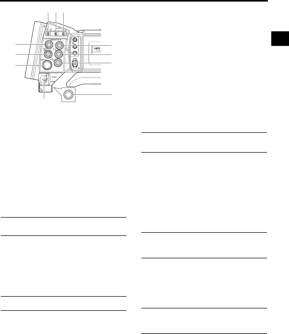
a[STUDIO] Studio terminal (Round 10-pin)
Connect the studio cable from the KA-HD250 Studio Kit
(sold separately). Connect the KA-HD250 to use this
device as a studio camera.
For details, refer to the KA-HD250 INSTRUCTION MAN-
UAL.
b[DC INPUT] DC input terminal (XLR 4-pin)
This is the 12V DC power input terminal. Connect to the
AC adapter.
When a battery is installed and a cable is connected to this
terminal, power supply from the battery stops and power is
supplied by this terminal.
c[GENLOCK/AUX IN] GENLOCK/AUX IN switch
Set according to the signal input in the [GENLOCK/AUX
IN] terminal.
GENLOCK : Set to this when inputting external synchroni-
zation signals.
AUX IN : Set to this when inputting composite video
signals from an external device.
MEMO
If no signals are input to the [AUX IN] terminal and this
switch is set to AUX IN, the monitor turns black and video is
not output from any terminal.
d[PBPR/TC] PBPR/Time code switch
Set according to the [PB/TC IN] and [PR/TC OUT] terminal
signals.
PBPR: Set to this when outputting component PB signals
from the [PB/TC IN] terminal and outputting com-
ponent PR signals from the [PR/TC OUT] terminal.
TC : Set to this when inputting LTC time code from the
[PB/TC IN] terminal and outputting the built-in time
code generator from the [PR/TC OUT] terminal.
MEMO
When this switch is set to TC, video is not output from the
Y/PB/PR terminal (i j k).
e[IEEE1394] IEEE1394 switch
Set according to the image format of the input/output sig-
nal and playback signal of the IEEE1394 terminal.
HDV : Set to this for HDV format.
DV : Set to this for DV format.
f[REMOTE] REMOTE terminal (Round 6-pin)
Some functions of this camera can be controlled exter-
nally.
Connect to a remote control unit (RM-LP55/RM-LP57).
XSee “Connect a Remote Control Unit (RM-LP55/RM-
LP57)” on page 71.
g[GENLOCK/AUX IN] GENLOCK/AUX IN terminal (BNC)
• Input synchronization signals in this terminal when
externally synchronizing camera images or playback
images.
Synchronization signal: BB (Black Burst) signal of SD
or Tri sync signal of HD
• Input composite video signals to record images from an
external device with this device.
• Select the signal to input with the [GENLOCK/AUX IN]
switch c.
XSee “Using GENLOCK Functions” on page 66.
XSee “Recording Composite Video Signals from an
External Device” on page 65.
h[HD/SD-SDI] HD/SD-SDI output terminal (BNC)
Outputs HD/SD-SDI (Serial Digital Interface) signals. Out-
puts embedded audio signals as digital audio.
The sampling frequency for embedded audio is 48 kHz.
In addition, the time code for the built-in time code genera-
tor and playback time code are output.
XSee pages 20 and 21 for the signals that are enabled.
MEMO
Set whether or not to output SDI signals from this terminal
in HD/SD-SDI OUT of the VIDEO FORMAT[2/2] menu
screen.
i[Y] Component Y signal output terminal (BNC)
Outputs Y signal of component when the [PBPR/TC] switch
d is set to PBPR.
j[PB/TC IN] Component PB signal output/time code
input terminal (BNC)
• Outputs PB signal of component when the [PBPR/TC]
switch d is set to PBPR.
• Inputs time code when the [PBPR/TC] switch d is set to
TC. Enter the LTC time code to slave lock this device’s
time code generator with an external time code genera-
tor.
MEMO
Set TCG SOURCE on the TC/UB/CLOCK Menu screen to
EXTERNAL to input external time codes.
XSee “Synchronizing with an External Time Code Gener-
ator” on page 49.
k[PR/TC OUT] Component PR signal output/time code
output terminal (BNC)
• Outputs PR signal of component when the [PBPR/TC]
switch d is set to PBPR.
• Outputs the LTC time code of the built-in time code gen-
erator when the [PBPR/TC] switch d is set to TC.
MEMO
Set the [Y/PB/PR] terminal (i j k) output image signal to
RGB or Y/C video signals in OUTPUT TERM. [DV] on the
VIDEO FORMAT[2/2] menu screen. (Only for DV format)
XSee “OUTPUT TERM. [DV]” on page 79.
IEEE 1394
CH2-AUDIO OUT-CH1 VIDEO
g
b
cde
f
j
i
h
k
a
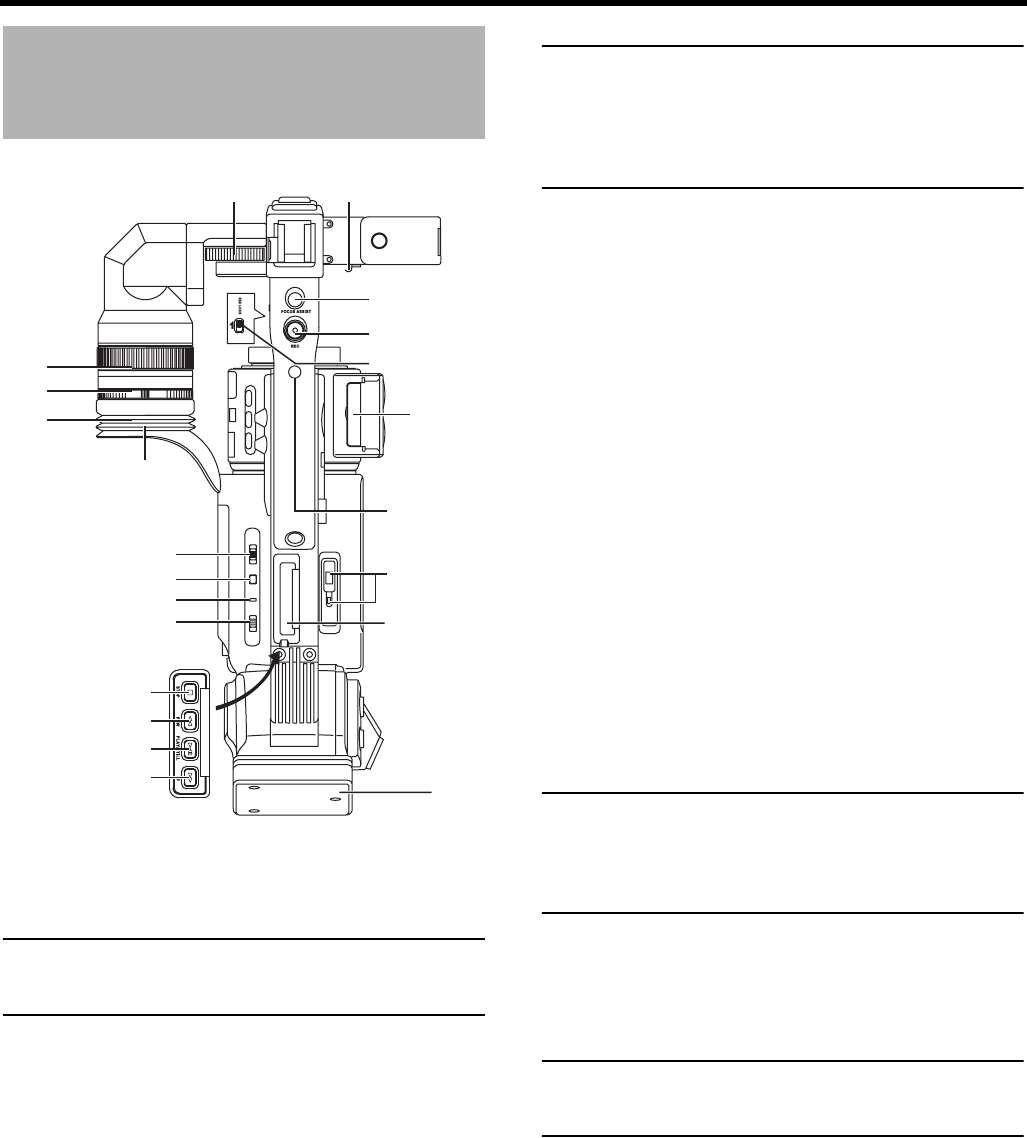
CONTROLS, INDICATORS AND CONNECTORS
18
Top Section
1Viewfinder
Displays the camera image and the playback picture.
MEMO
Set the image format for the viewfinder to RGB, compo-
nent, composite, or Y signal in VF SIGNAL on the LCD/
VF[4/4] menu screen. XSee page 92.
2Eyepiece
Ensures that ambient light does not reach the viewfinder
screen or falls into the eye of the cameraman.
3Eyepiece focus ring
You can adjust the focus by turning this ring.
4Eyepiece mounting ring
You can adjust the position of the eyepiece forward or
backward by loosening this ring.
5Slide mounting ring
You can adjust the position of the viewfinder left or right by
loosening this ring.
6Clamp
Attach the microphone cable here.
7[FOCUS ASSIST] Focus assist button
When you press this button during shooting, the area of
focus is displayed in blue, red or green, making it easy to
focus accurately.
MEMO
• When FOCUS ASSIST on the LCD/VF[1/4] menu screen
is set to ACCU-FOCUS and this button is pressed,
ACCU FOCUS functions with FOCUS ASSIST. This
makes depth of field shallower, making it easier to focus.
• This button has the same function as the FOCUS
ASSIST button 6 in the Right Side Section.
XSee “LCD/VF[1/4] Menu Screen” on page 89.
8[REC] REC trigger button (start/stop recording)
Start and stop recording using this button.
(This works together with the REC trigger button on the
right panel and the lens VTR trigger button.)
9[REC LOCK] REC LOCK switch
Slide this switch in the direction of the arrow to lock the
[REC] trigger button 8. Use this to prevent unwanted
recording.
(The REC trigger button on the right panel and the lens
VTR trigger button are not locked.)
0SD memory card cover
When you open this cover, you can insert and remove the
SD memory card.
XSee “Inserting an SD Memory Card” on page 34.
When an SD memory card is loaded
• You can save, call up and reset the menu settings on
GY-HD250/GY-HD251.
• You can initialize (format) an SD memory card.
XSee “FILE MANAGE Menu Screen” on page 100.
a[EJECT] Eject switch and LED
Slide this switch to the side to insert or eject a videocas-
sette tape.
The LED lights while ejecting is in progress.
MEMO
• It takes a few seconds before the videocassette is
ejected. Do not close the cassette cover during the eject
operation.
• Do not touch the cassette insertion slot or cassette dur-
ing the eject operation. This could result in damage.
bOperation cover
Open this cover when operating in the playback mode.
Otherwise, keep this cover closed.
This cover can be opened by sliding it to the side.
MEMO
When the STOP button h is pressed in the Camera mode
to set the VTR operation mode indicator to indicate STOP,
playback operations become possible.
cBattery adapter
Attach the battery.
U model: Anton Bauer battery
E model: IDX battery
XSee “Battery Operation” on page 37.
1
2
3
4
56
7
8
9
0
a
b
c
d
h
i
j
k
e
f
g
l

19
d[MONITOR SELECT] Audio monitor selector switch
This switch is used to select the monitor sound output and
playback sound output from the monitoring speaker 1 on
page 14 or the PHONES jack 2 on page 12.
XSee “Outputting Audio” on page 63.
XSee “AUDIO/MIC[2/2] Menu Screen” on page 88.
CAUTION
Make sure to move switches all the way. Do not leave a
switch stopped in a midway position. Noise will be gener-
ated and operation irregularities will occur.
e[DISPLAY] Display button
• When LCD+VF in the LCD/VF[4/4] menu display is set
to OFF, press the DISPLAY button for 2 seconds to
switch between the LCD screen and the viewfinder
screen.
• When LCD+VF in the LCD/VF[4/4] menu display is set
to ON, press the DISPLAY button for 2 seconds to
switch the LCD screen ON and OFF. Press the DIS-
PLAY button briefly to change the display mode for the
LCD screen as follows.
XSee “Magnified Status Indications on the LCD Monitor”
on page 29.
f[VTR] VTR indicator
This indicator lights when the camera is in the VTR mode.
To perform VTR playback or to input the HDV/DV signal
from the IEEE1394 connector 0 on page 16, press the
CAM/VTR button 5 on page 13 to turn on this indicator.
It flashes when the mode is being changed.
g[FULL AUTO] Full auto shooting (FAS) switch
This is the ON/OFF switch for FAS mode.
• During FAS mode, “FAS” is displayed on the LCD moni-
tor or the viewfinder.
• FAS mode works together with the auto iris and auto
level control (ALC) modes and automatically adjusts to
the optimal video signal level and white balance.
• You can select automatic adjustment mode or manual
adjustment mode for audio recording level.
XSee “AUDIO/MIC[2/2] Menu Screen” on page 88.
• Even if there are color bars, this automatically sets to
camera video.
• Auto iris mode operates even if the lens iris mode
switch is set to the manual position.
• The gain changes continuously until it reaches the max-
imum ALC MAX setting, and the shutter speed also
changes continuously.
• When you release FAS mode, all of the settings return
to their previous modes.
CAUTION
When the power is turned on while the camera is in the
FAS mode, it takes about 10 seconds before the automatic
adjustment of FAS is completed.
All of the previous setting contents are recalled when the
FAS mode is cancelled.
h[STOP] Stop button
Press to enter the stop mode.
i[REW] Rewind button
Press this button to rewind the tape.
• Pressing this button in the stop or fast forward mode ini-
tiates the rewind mode. (Only for VTR mode)
• Pressing this button during playback, still picture play-
back or forward search initiates reverse search.
j[PLAY/STILL] Play/still button
Press to start playback. Press to enter the still picture
mode during playback, in the stop mode or in the search
mode.
Depending on the ambient temperature, if still image play-
back mode continues for between 30 seconds and 3 min-
utes, it stops automatically. (Tape protect mode)
During still picture playback and search mode, press this
button to return to the normal playback mode.
* If the auto tracking is active at the moment the play
mode is entered, the playback video will be interfered
with digital noise.
k[FF] Fast forward button
Press this button to fast forward the tape.
• Pressing this button in the stop or rewind mode initiates
the fast forward mode. (Only for VTR mode)
• Pressing this button during playback, still picture play-
back or reverse search initiates forward search.
lScrew holes for mounting accessories
You can mount lights and other accessories.
CH-1 : The CH-1 channel audio is output.
BOTH : CH-1 and CH-2 channel audio are output mixed.
When this setting is selected, the menu screen
can be used to select whether the mixed sound
or stereo sound should be output via the
PHONES jack. (AUDIO MONITOR item on the
AUDIO/MIC[2/2] menu screen)
When AUDIO MONITOR item on the AUDIO/
MIC[2/2] menu screen is set to “STEREO”, only
the audio of CH-1 is output from the monitoring
speaker.
CH-2 : The CH-2 channel audio is output.
Characters shown enlarged
Image and characters displayed
Only image displayed
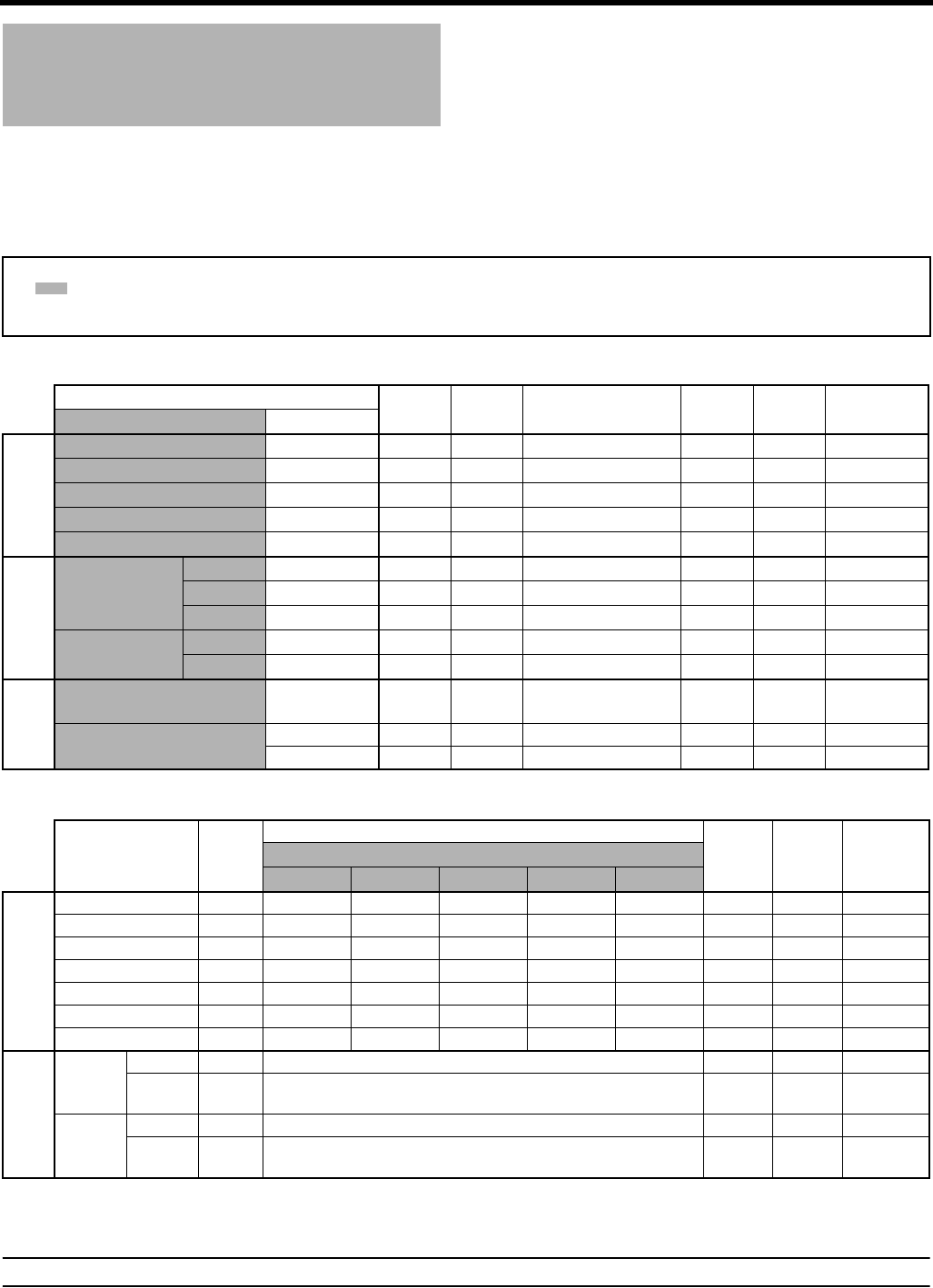
CONTROLS, INDICATORS AND CONNECTORS
20
Recording and Image Out-
put Formats
This device supports HDV and DV image formats, as well as images input from external devices. This device also has various
output terminals. (Composite, analog component, HD/SD-SDI, IEEE1394)
Select analog component, RGB or Y/C signals for images from the Y/PB/PR terminal in DV format.
(Select in OUTPUT TERM. [DV] on the VIDEO FORMAT[2/2] menu screen)
During recording and playback, image formats from each of the output terminals are as shown in the table below.
When recording camera images
In PLAY mode
*1 When HDV PB OUTPUT is set to NTSC, 480/60i format video signal is output.
*2 When HDV PB OUTPUT is set to PAL, 576/50i format video signal is output.
MEMO
Synchronize the setting for FRAME RATE in the VIDEO FORMAT menu screen with the frame rate of the playback signal.
Notes about the table
(Shaded): Indicates the setting item in the VIDEO FORMAT menu screen.
N/A: Terminal is not available.
q: Same format as the left.
Recording (Shooting) Rec on
Tape
IEEE
1394 Out
Component / SDI Out
(EE Out) RGB Out Y/C Out Composite
Out
[REC] menu item Format
HD
(HDV)
HDV-HD60P 720/60p qq q N/A N/A 480/60i
HDV-HD30P 720/30p qq 720/60p N/A N/A 480/60i
HDV-HD50P 720/50p qq q N/A N/A 576/50i
HDV-HD25P 720/25p qq 720/50p N/A N/A 576/50i
HDV-HD24P 720/24p qq 720/60p N/A N/A 480/60i
DV
U model only
DV-60I 480/60i qqqqqq
DV-24P 480/60i(24p) qqqqqq
DV-24PA 480/60i(24p) qqqqqq
E model only DV-50I 576/50i qqqqqq
DV-25P 576/50i(25p) qqqqqq
HD
[1080I CAMERA]
menu item Frame rate Rec on
Tape
IEEE
1394 Out Component / SDI Out RGB Out Y/C Out Composite
Out
ON 60/30 N/A N/A 1080/60i N/A N/A 480/60i
50/25 N/A N/A 1080/50i N/A N/A 576/50i
Playback
IEEE
1394
Out
Component / SDI Out
RGB Out Y/C Out Composite
Out
[HDV PB OUTPUT] menu item
NATIVE 720P 1080I NTSC PAL
HDV
720/60p qq q1080/60i 480/60i N/A 480/60i*1 480/60i*1 480/60i
720/30p q720/60p q1080/60i 480/60i N/A 480/60i*1 480/60i*1 480/60i
720/50p qq q1080/50i N/A 576/50i 576/50i*2 576/50i*2 576/50i
720/25p q720/50p q1080/50i N/A 576/50i 576/50i*2 576/50i*2 576/50i
720/24p q720/60p q1080/60i 480/60i N/A 480/60i*1 480/60i*1 480/60i
480/60p N/A N/A N/A N/A N/A N/A N/A N/A N/A
576/50p N/A N/A N/A N/A N/A N/A N/A N/A N/A
DV
U model
480/60i qq qqq
480/
60i(24p) qq qqq
E model
576/50i qq qqq
576/
50i(25p) qq qqq
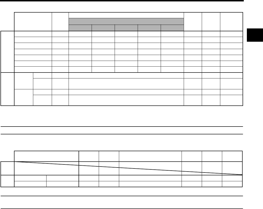
21
When Recording HDV or DV Images from the IEEE1394 Terminal
*1 When HDV PB OUTPUT is set to NTSC, 480/60i format video signal is output.
*2 When HDV PB OUTPUT is set to PAL, 576/50i format video signal is output.
MEMO
Synchronize the setting for FRAME RATE on the VIDEO FORMAT menu screen with the frame rate of the IEEE1394 input signal.
When Recording Composite Images from the AUX IN Terminal
MEMO
• For the U model, set REC on the VIDEO FORMAT[1/2] menu screen to DV-60I.
• For the E model, set REC on the VIDEO FORMAT[1/2] menu screen to DV-50I.
Recording
(IEEE1394 In)
Rec on
Tape
Component / SDI Out
RGB Out Y/C Out Composite
Out
[HDV PB OUTPUT] menu item
NATIVE 720P 1080I NTSC PAL
HDV
720/60p qq q1080/60i 480/60i N/A 480/60i*1 480/60i*1 480/60i
720/30p q720/60p q1080/60i 480/60i N/A 480/60i*1 480/60i*1 480/60i
720/50p qq q1080/50i N/A 576/50i 576/50i*2 576/50i*2 576/50i
720/25p q720/50p q1080/50i N/A 576/50i 576/50i*2 576/50i*2 576/50i
720/24p q720/60p q1080/60i 480/60i N/A 480/60i*1 480/60i*1 480/60i
480/60p N/A N/A N/A N/A N/A N/A N/A N/A N/A
576/50p N/A N/A N/A N/A N/A N/A N/A N/A N/A
DV
U model
480/60i qq qqq
480/
60i(24p) qq qqq
E model
576/50i qq qqq
576/
50i(25p) qq qqq
Recording (Composite In) Rec on
Tape
IEEE
1394 Out Component/SDI Out (EE Out) RGB Out Y/C Out Compos-
ite Out
HD
SD U model 480/60i qq q qqq
E model 576/50i qq q qqq

CONTROLS, INDICATORS AND CONNECTORS
22
Indications on the LCD
Monitor and in the View-
finder
In addition to showing the EE image and the playback pic-
ture, the LCD monitor and viewfinder are also used for the
following character displays.
To show characters on the LCD monitor, press the DISPLAY
button briefly.
Status screens (screens for checking the current cam-
era settings)
Auto white display (only displayed in the Camera
mode)
Menu setting screens
Alarm message display
Safety zone display (only displayed in the Camera
mode)
MEMO
When ANALOG OUT CHAR. on the OTHERS[1/2] menu
screen is ON, characters are also shown on images from
the Y/PB/PR OUT and VIDEO OUT terminals.
Characters are also shown on images from the HD/SD-SDI
OUT terminal when the SDI OUT CHAR. is ON.
Status Screens
Press the STATUS button while normal screen is displayed
to show one of the status screens.
The contents of the status display are divided into those for
the Camera mode and those for the VTR mode.
• Each time the STATUS button is pressed in the Camera
mode, one of 5 status screens is displayed. (STATUS 0, 1,
2, 3, 4)
• One type of screen is displayed in the VTR mode.
• CAMERA MODE (display example)
MEMO
• When the STATUS button is pressed for 1 second or
longer, the menu setting screen is displayed.
To display the Status screen while the menu setting
screen is displayed, press the STATUS button to return
to the normal screen.
• You can switch between the LCD monitor and the view-
finder by holding down the DISPLAY button for about 2
seconds. (When the LCD+VF item on the LCD/VF[4/4]
menu screen is set to OFF.)
DISPLAY button
USER 3USER 2USER 1
STATUS
MENU
2
1
ND FILTER
SHUTTER
STATUS button
STATUS 1STATUS 0
STATUS 2
STATUS 4
STATUSSTATUS 3
•VTR MODE
(display example)
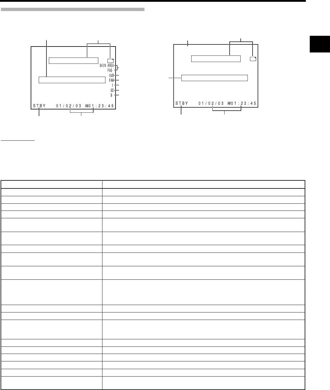
23
Status Screens in the Camera Mode
STATUS 0
1Event Indication
When the Gain or Shutter Speed is changed manually, the setting condition is displayed for about 3 seconds at the time the
change is made.
• Set the shutter display method to seconds or angle in SHUTTER DISP. on the LCD/VF[3/4] menu screen. (Only when
frame rate is 24p or 25p mode)
266S
DD
STATUS 0 Screen
1
23
9
8
7
6
5
4
0
STATUS 0 Screen
External Image Input Mode (AUX IN)
DV-60I AUX
266S
DD
a0
1
23
Setting Status Contents of Indications
Gain value was changed GAIN 0 dB, 3 dB, 6 dB, 9 dB, 12 dB, 15 dB, 18 dB
Gain value reached the ALC GAIN ALC
FULL AUTO was turned ON/OFF FULL AUTO ON, FULL AUTO OFF
ZEBRA was turned ON/OFF ZEBRA ON, ZEBRA OFF
Shutter speed value was changed *1
(When SHUTTER DISP. is set to SEC)
SHUTTER 1/6, 1/6.25, 1/7.5, 1/12, 1/12.5, 1/15, 1/24, 1/25, 1/30, 1/48, 1/50, 1/60, 1/100, 1/120,
1/250, 1/500, 1/1000, 1/2000, 1/4000, 1/10000
Variable shutter speed value was changed *1
(When SHUTTER DISP. is set to SEC)
V. SHUTTER 1/24.01 to 1/10489.5
Shutter was turned OFF SHUTTER OFF [1/**] *4
Shutter speed value was changed
(When SHUTTER DISP. is set to DEG)
SHUTTER 360.0°, 180.0°, 172.8°, 150.0°, 144.0°, 135.0°, 120.0°, 105.0°, 90.0°, 75.0°, 60.0°,
45.0°, 30.0°, 22.5°, 11.2°
Variable shutter speed value was changed
(When SHUTTER DISP. is set to DEG)
24p: 0.82° to 359.4°
25p: 0.85° to 359.4°
White balance value was changed (Example)
WHITE BAL A [3200K]
Numeric value: Any of 2300, 2500, 2800, 3000, 3200, 3400, 3700, 4300, 5200, 5600, 6500,
8000
FILTER value was changed FILTER OFF, FILTER ND 1 [1/4ND], FILTER ND 2 [1/16ND]
AE LEVEL value was changed *2 AE LEVEL –3, –2, –1, NORMAL, +1, +2, +3
BLACK gain value was changed *2 BLACK NORMAL
BLACK STRETCH 1, 2, 3, 4, 5
BLACK COMPRESS 1, 2, 3, 4, 5
PRESET TEMP. value was changed *2 *3 WHITE BAL PRST [3200K], WHITE BAL PRST [5600K]
HEADER REC is running HEADER REC
FOCUS ASSIST was turned ON/OFF FOCUS ASSIST ON, FOCUS ASSIST OFF
Time code was set to zero reset TC ZERO PRESET XSee page 45.
REC LOCK switch was turned ON/OFF REC SWITCH LOCKED, REC SWITCH UNLOCKED XSee page 18, 9 REC LOCK switch.
A REC command was sent from the IEEE1394
connector
TRIGGER TO HDV, TRIGGER TO DV
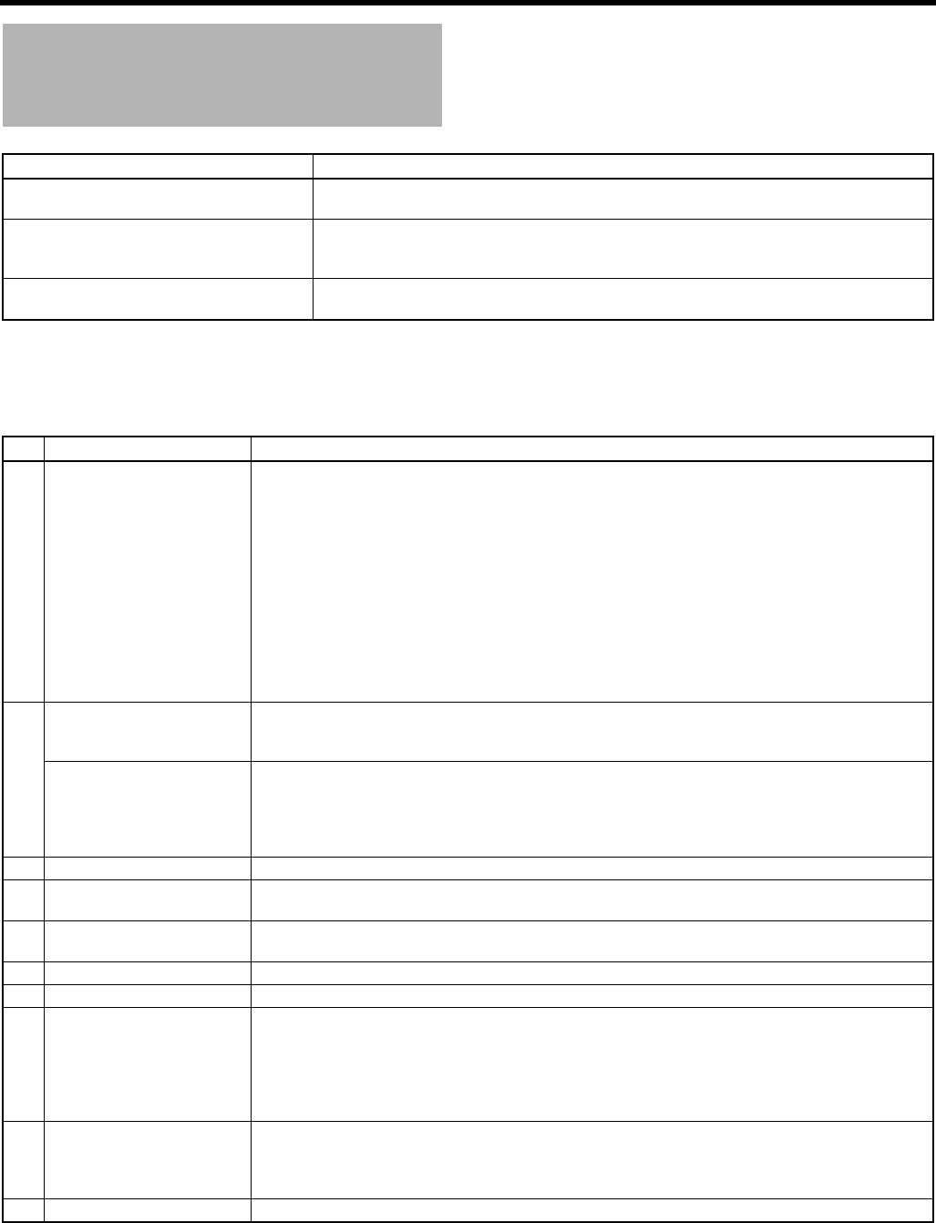
CONTROLS, INDICATORS AND CONNECTORS
24
Indications on the LCD Monitor
and in the Viewfinder (Cont’d)
*1 The range for the shutter speed differs depending on the video format setting. XSee page 86.
*2 Displayed if functions were assigned to the USER1 - 3 buttons. XSeepage86.
*3 Displayed when the [WHT.BAL] white balance selector switch c on page 15 is set to PRST (PRESET).
*4 “ ** ” depends on the video format.
Setting Status Contents of Indications
FF/REW button was pressed in CAMERA
mode
SWITCH TO VTR MODE
REC/VTR trigger button was pressed when
1080I CAMERA in the VIDEO FORMAT[1/2]
menu screen was set to ON
1080I REC INVALID
Other Displays XSee “FILE MANAGE Menu Screen” on pages 100-102.
XSee “Warnings and Responses” on page 106.
No. Item Contents
2VTR mode indication STBY : In record standby mode (record-pause mode)
REC : During recording
PLAY : During playback
FF : During fast forward
REW : During rewind
STL : During still picture playback mode
FWD : During playback in forward direction (FWD1: About ×2 speed, FWD2: About ×5 speed, FWD3:
About ×10 speed)
REV : During playback in reverse direction (REV1: About ×2 speed, REV2: About ×5 speed, REV3:
About ×10 speed)
STOP : Stop mode (Tape protect mode)
EJECT : Cassette being ejected
- - - : No tape loaded
3Indication of date and time Indicates the date and time.
Whether or not the date and time should be displayed as well as the display style are set on the TIME/
DATE menu.
LCD BRIGHT indication When the brightness of the monitor screen is adjusted with the LCD BRIGHT button, the date and time
indications and the VTR mode indication 2 are turned off and the LCD BRIGHT indicator is displayed.
(Example)
BRIGHT +5 •••••+•••••O
Numeric value: Any of –5, –4, –3, –2, –1, 0, +1, +2, +3, +4, +5.
4Indication of Black operation B : Displayed when the black stretch or black compress settings are other than NORMAL.
5Indication of skin tone detail
color operation
SD : Indicated when skin tone detail is ON.
6Indication of Iris level opera-
tion
I : Displayed when the AE LEVEL setting is other than NORMAL
7Indication of FAW operation FAW : Indicated when Full Auto White Balance is ON.
8Gain operation indication * dB : Indicates gain value when gain is other modes than 0 dB and ALC.
9Indication of various function
operations
FOCUS : Displayed when the Focus Assist function is ON.
SKIN AREA : Blinks while the skin detail color area is displayed.
ALC : Displayed when ALC function alone is ON.
FAS : Displayed when the Full Auto Shooting function is ON.
S : Displayed when the shutter speed is a setting other than the default setting.
XSee page 86.
0Indication of DR-HD100 Oper-
ation
When a DR-HD100 (HDD unit by FOCUS enhancements) is connected, its operation status is displayed.
[: DR-HD100 is connected (displays white)
[: Recording with DR-HD100 (displays red)
(For details, refer to the DR-HD100 INSTRUCTION MANUAL.)
aAUX display Displays when in external image input mode. (AUX IN mode)
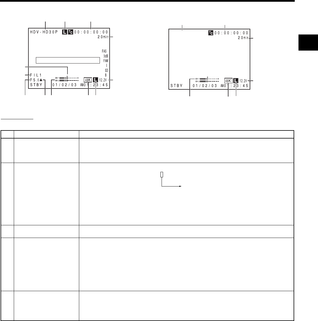
25
STATUS 1
In addition to the information on the STATUS 0 screen, this screen displays the following items.
STATUS 1 Screen
12
4
5
9
0
a
8
STATUS 1 Screen
External Image Input Mode (AUX IN)
DV-60I AUX
32
4
5
c
67
76b b
No. Item Contents
1VIDEO FORMAT display Displays the currently selected video format.
Allows you to select the REC item on the VIDEO FORMAT[1/2] menu screen. XSee page 77.
You can switch this display ON/OFF using the VIDEO FORMAT item on the LCD/VF[3/4] menu screen.
XSee page 91.
2Time Code (TC)/User’s Bits
(UB) indication
Indicates the time code (h:m:s:frame) or user’s bits data.
Whether or not to display this item is set with the TC/UB item on the LCD/VF[3/4] menu screen.
XSee page 91.
Whether the time code or user’s bits should be shown is selected with the TC DISPLAY switch inside the
LCD door.
3Synchronized display with an
external time code generator
Lights up when the time code generator of this device synchronizes with the time code input from the TC
IN terminal. Blinks when synchronization is unsuccessful. Turns off If there is no input signal.
4Remaining tape indication Remaining tape indication (displayed in 1-minute steps)
This indicator blinks when remaining tape time is equivalent to less than 3 minutes.
Whether or not to display this item is set with the TAPE REMAIN item on the LCD/VF[3/4] menu screen.
XSee page 91.
* When inserting a brand-new tape, the remaining tape time is not indicated.
When the tape has been run, the indication will appear.
* The remaining tape indication is to be regarded only as a guide.
* When this device is used at low temperatures, it may take a while before the indication of the remaining
tape time appears.
5Voltage indication (Example) 12.2V: Indicates remaining battery level in 0.1V steps.
Battery voltage and remaining battery are displayed. Select the display method in BATTERY INFO. on the
LCD/VF[3/4] menu screen. XSee page 91.
Anton Bauer battery: Voltage/remaining capacity (%)/remaining time
IDX Endura battery : Voltage/remaining capacity (%)
(Example) Time code TC 00 : 00 : 00 : 00
User’s bits UB FF EE DD 20
Colon (:) when non-drop frame mode
Dot (.) when drop frame mode

CONTROLS, INDICATORS AND CONNECTORS
26
Indications on the LCD Monitor
and in the Viewfinder (Cont’d)
No. Item Contents
6Audio sampling frequency in-
dication
32 K : Indicated when the AUDIO MODE item on the AUDIO/MIC[1/2] menu screen is set to 32 K. (Audio
is recorded with 12-bit, 32 kHz sampling.)
48 K : Indicated when the AUDIO MODE item on the AUDIO/MIC[1/2] menu screen is set to 48 K. (Audio
is recorded with 16-bit, 48 kHz sampling.) When HDV format is set, 48K is displayed.
XSee page 87.
Whether or not to display this item is set with the AUDIO item on the LCD/VF[3/4] menu.
7Audio level meter indication Displays the CH-1, CH-2 audio level meters.
Whether or not to display this item is set with the AUDIO item on the LCD/VF[3/4] menu.
XSee page 91.
8Standard audio level indication The level at which audio is recorded on the tape is indicated by “O”.
–20 dB, –12 dB
XSee “AUDIO REF.LEVEL” on page 87.
9Iris indicator display M: Iris set higher than normal
b: Iris set to normal
N: Iris set lower than normal
The indication can be switched ON/OFF with the F.NO/IRIS IND. item on the LCD/VF[1/4] menu screen.
XSee page 89.
0Iris F-value indication Indicates the F-number of the connected lens.
OPEN, F2, F2.8, F4, F5.6, F8, F11, F16, CLOSE
It is not displayed when the lens is removed. For some lenses, no display appears.
The indication can be switched ON/OFF with the F.NO/IRIS IND. item on the LCD/VF[1/4] menu screen.
XSee page 89.
aFilter position indication Indicates the current filter position.
No display : FILTER OFF
ND1 : FILTER ND1 (1/4ND)
ND2 : FILTER ND2 (1/16ND)
The indication can be switched ON/OFF with the FILTER item on the LCD/VF[1/4] menu screen.
XSee page 89.
bAudio Lock Indication Displayed when the audio signal is locked to the video signal.
cAUX display Displays when in external image input mode (AUX IN mode)
–20 dB –12 dB
OO
CH-1 OOOOOOOOO\\\]
CH-2 OOOOOOOOO\\\]
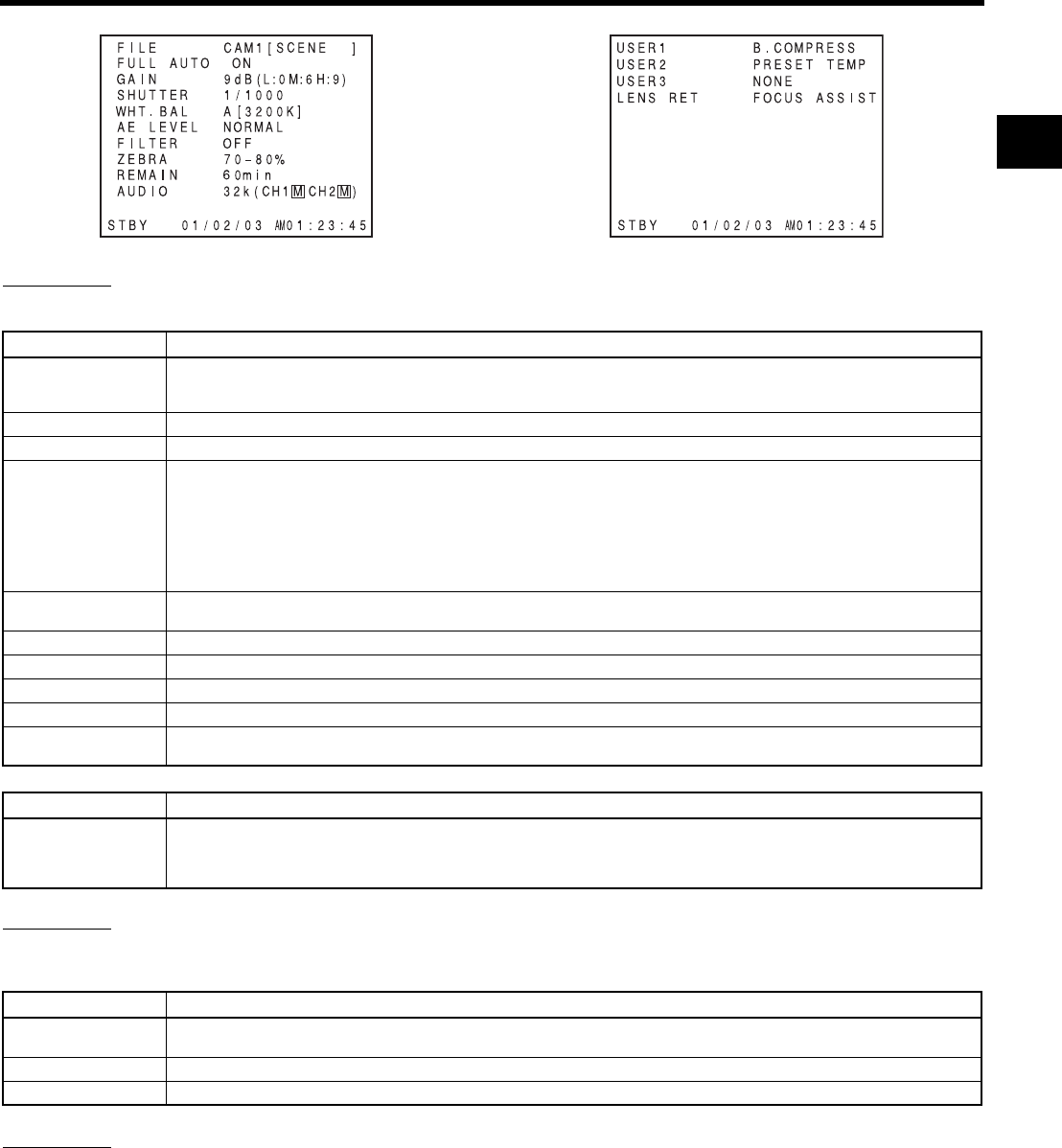
27
STATUS 2
This screen displays the camera setup statuses.
Event display is not available while this screen is displayed.
* When SHUTTER DISP. on the LCD/VF[3/4] menu screen is set to DEG, the shutter display for the frame rate in 24p or 25p mode is degrees.
STATUS 3
Displays a list of setting statuses for USER1, 2, and 3 as well as LENS RET item on the SWITCH MODE menu screen.
XSee page 86.
Events are not displayed while these statuses are being displayed.
STATUS 4
This screen only displays VTR mode indication, date and time, event display and alarm indications.
* Whether or not date and time should be displayed and the display style are set on the TIME/DATE menu screen.
XSee “Displaying the Time and Date on the Screen” on page 42.
STATUS 2 Screen STATUS 3 Screen
Indication Indication Contents
FILE FILE F CAM1 [********], CAM2-4 [********], and EXT1 - 4 [********] * indicates SUB NAME XSee pages 100-102.
A F symbol is displayed when a menu setting read from LOAD FILE was changed.
The display disappears when the setting is saved using STORE FILE.
FULL AUTO ON, OFF
GAIN 0dB, 3dB, 6dB, 9dB, 12dB, 15dB, 18dB, ALC
SHUTTER*(When STEP is selected)
OFF, 1/6, 1/6.25, 1/7.5, 1/12, 1/12.5, 1/15, 1/24, 1/25, 1/30, 1/48, 1/50, 1/60, 1/100, 1/120, 1/250, 1/500, 1/1000, 1/2000,
1/4000, 1/10000
(When VARIABLE is selected)
1/24.01 - 1/10489.5
(Displayed when FAS or ALC mode is selected)
EEI
* The range for the shutter speed differs depending on the video format. XSee page 86.
WHT. BAL A[##00K], B[##00K], PRESET[##00K], FAW, MANUAL (Only when the remote control unit is used)
For A and B, ## represents 23, 25, 28, 30, 32, 34, 37, 43, 52, 65, or 80. For PRESET, 32 or 56.
AE LEVEL –3, –2, –1, NORMAL, +1, +2, +3
FILTER OFF, ND1 [1/4ND], ND2 [1/16ND]
ZEBRA 60-70%, 70-80%, 85-95%, OVER 95%, OVER 100%
REMAIN Displays the remaining tape (minutes)
AUDIO Displays the audio sampling frequency and the audio level adjustment mode (Ex: 32K (CH1 Z CH2 a) Z (for AUTO
mode) a (for MANUAL mode)
Indication Indication Contents
SHUTTER (When STEP is selected)
360.0°, 180.0°, 172.8°, 150.0°, 144.0°, 135.0°, 120.0°, 105.0°, 90.0°, 75.0°, 60.0°, 45.0°, 30.0°, 22.5°, 11.2°
(When VARIABLE is selected)
24p: 0.82° to 359.4°, 25p: 0.85° to 359.4°
Indication Indication Contents
USER1
USER2
NONE, BARS, PRESET TEMP., B.STRETCH1 to 5, B.COMPRESS1 to 5, AE LEVEL+, AE LEVEL–, RET, LOAD FILE
USER3 NONE, BARS, PRESET TEMP., B.STRETCH1 to 5, B.COMPRESS1 to 5, RET, LOAD FILE
LENS RET RET, FOCUS ASSIST
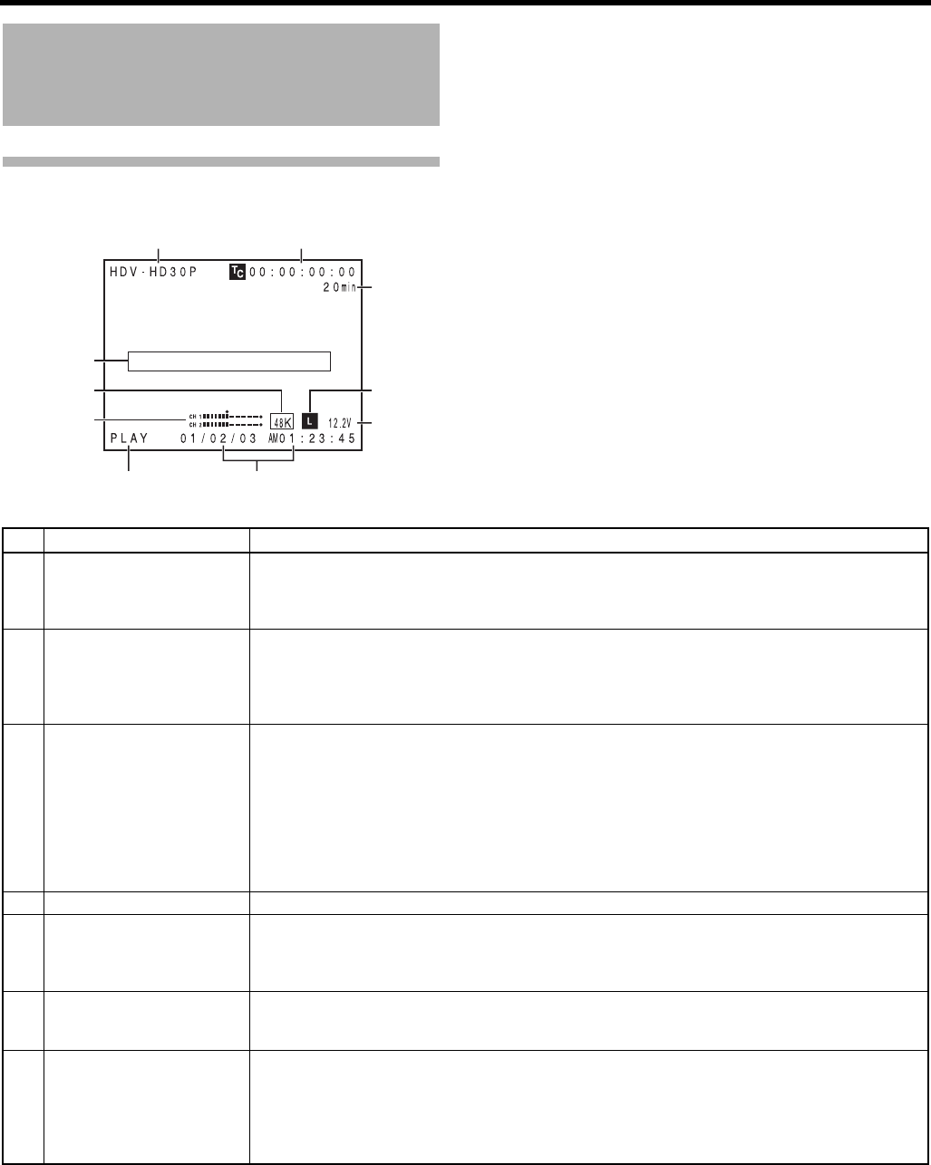
CONTROLS, INDICATORS AND CONNECTORS
28
Indications on the LCD Monitor
and in the Viewfinder (Cont’d)
Status Screen in VTR MODE
12
3
9
4
5
6
78
0
No. Item Contents
1VIDEO FORMAT display Displays the video format recorded on the tape when in VTR mode. Also displays the video format of the
HDV/DV input signal.
You can switch this display ON/OFF using the VIDEO FORMAT item on the LCD/VF[1/2] menu screen.
XSee page 91.
2Time code (TC) and user’s bits
(UB) display
Displays the time code data being recorded (hour, minute, second, frame) when in VTR mode.
You can switch this display ON/OFF using the TC/UB item on the LCD/VF[1/2] menu screen.
XSee page 91.
You can select to display either the time code or the user’s bits using the TC DISPLAY switch in the LCD
door.
3Remaining tape time Remaining tape indication (displayed in 1-minute steps)
This indicator blinks when remaining tape time is equivalent to less than 3 minutes.
Whether or not to display this item is set with the TAPE REMAIN item on the LCD/VF[1/2] menu screen.
XSee page 91.
* When inserting a brand-new tape, the remaining tape time is not indicated.
When the tape has been run, the indication will appear.
* The remaining tape indication is to be used only as a guide.
* When this device is used at low temperatures, it may take a while before the indication of the remaining
tape time appears.
4Event display Displays messages related to VTR operations. XSee pages 106-108.
5Audio sampling frequency in-
dication
The audio sampling frequency used for the recording is displayed during playback.
(32 K, 48 K, 44.1 K)
Whether or not to display this item is set with the AUDIO item on the LCD/VF[1/2] menu screen.
XSee page 91.
6Audio level meter indication Displays the audio level meters during playback.
Whether or not to display this item is set with the AUDIO item on the LCD/VF[1/2] menu screen.
XSee page 91.
7VTR mode indication Indicates the VTR operation status
STBY, STOP, PLAY, REC, FF, REW, FWD, REV, STL, - - - (No tape loaded), SLOW: During variable play-
back in forward direction (Displayed when using non-linear editing software.)
(SLOW+1: About ×0.1 speed, SLOW+2: About ×0.2 speed, SLOW+3: About ×0.5 speed)
During variable playback in reverse direction (Displayed when using non-linear editing software.)
(SLOW–1: About ×–0.1 speed, SLOW–2: About ×–0.2 speed, SLOW–3: About ×–0.5 speed)
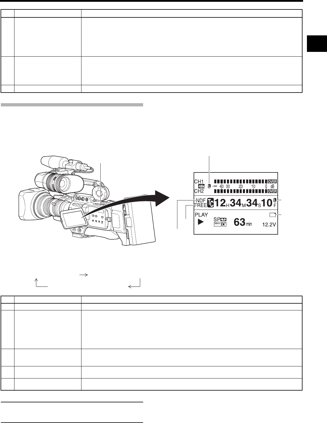
29
Magnified Status Indications on the
LCD Monitor
The characters on the status screens can be showed alone
in magnified size on the LCD monitor.
1. Set the LCD+VF item on the LCD/VF[4/4] menu screen to ON. XSee page 92.
2. When the DISPLAY button is briefly pressed while the LCD monitor is displayed, the displayed contents change every time the
DISPLAY button is pressed.
MEMO
When characters indicating the status are displayed in
magnified size on the LCD monitor, the viewfinder display
the image.
No. Item Contents
8Time/Date indication Recorded data are displayed during playback, fast forward, and rewind.
During recording in DV format, the data from the IEEE1394 connector is displayed.
During recording in HDV format, the data of internal clock is displayed.
Whether or not the date and time should be displayed and the display style are set on the TIME/DATE
menu screen. XSee page 95.
When the date and time have not been set, the following indication appears.
- -/- -/- - - -: - -: - -
9Voltage indication (Example) 12.2V : Indicates remaining battery level in 0.1V steps.
Battery voltage and remaining battery are displayed. Select the display method in BATTERY INFO. on the
LCD/VF[1/2] menu screen XSee page 91.
Anton Bauer battery: Voltage/remaining capacity (%)/remaining time
IDX Endura battery : Voltage/remaining capacity (%)
0Audio Lock indication Displayed when the audio signal from DV recording or playback is locked to the video signal.
No. Item Contents
1Audio Lock Indicator Displayed during recording and playback when the audio signal is locked to the video signal.
2Time Code Generator Setting
Indicator
Indicates the set status of the TC GENE switch on the side section.
FREE : TC GENE switch is set to PRESET-FREE RUN MODE.
RECR : TC GENE switch is set to PRESET-REC RUN MODE.
REGN : TC GENE switch is set to REGEN MODE.
DUPL : There is 1394 input in VTR mode and TC DUPLI. menu is set to ON.
EXT : Displays when time code is input to the TC IN terminal.
(When TCG SOURCE on the TC/UB/CLOCK menu screen is set to EXTERNAL.)
3Drop/Non-drop Indicator Indicates the framing mode of the time code.
DF : Drop frame mode
NDF : Non-drop frame mode
4Synchronized display with an
external time code generator
Lights up when the time code generator of this device synchronizes with the time code input from the TC
IN terminal. Blinks when synchronization is unsuccessful. Turns off If there is no input signal.
5Indication of DR-HD100 Oper-
ation
When a DR-HD100 (HDD unit by FOCUS enhancements) is connected, its operation status is displayed.
(For details, refer to the DR-HD100 INSTRUCTION MANUAL.)
266S
DD
DISPLAY button
1
3
2
5
4
Characters shown enlarged
Image and characters displayed
Only image displayed
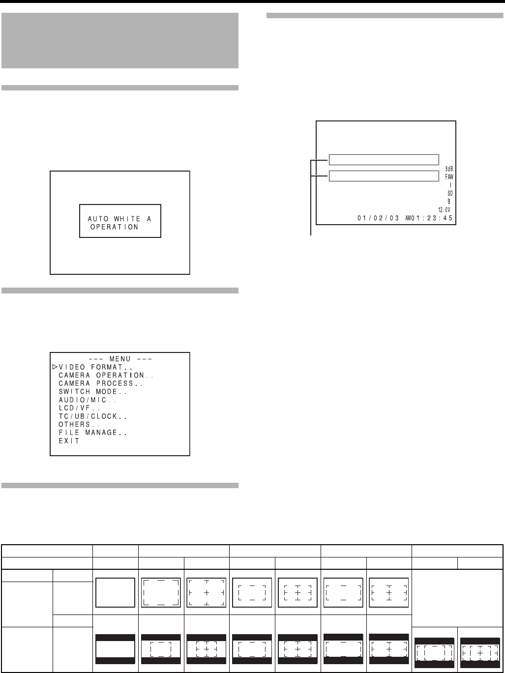
CONTROLS, INDICATORS AND CONNECTORS
30
Indications on the LCD Monitor
and in the Viewfinder (Cont’d)
Auto White Balance Indication
(Camera mode only)
The AUTO WHITE indication and the result of the operation are dis-
played during the auto white balance adjustment operation.
XSee “White Balance Adjustment” on page 52.
Menu Setting Screen
Screen used for making various settings.
The Menu Setting Screen appears when the STATUS button is
pressed for 1 second or more.
XSee “Setting Menu Screens” on page 75.
Alarm Message Display
• The following alarm messages are displayed while the STA-
TUS (0, 1, 4) screen is shown in the Camera mode, or a STA-
TUS screen is shown in the VTR mode.
If an alarm is generated while the STATUS 2, 3 screen is
shown, the STATUS 0 screen returns to display the alarm.
XSeepage106.
• When an abnormality occurs in the VTR, a warning message
with an error code is displayed.
XSee pages 106-108.
Safety Zone Indication (Camera mode only)
The indication of the following safety zone and center mark indications can be turned ON/OFF with the SAFETY ZONE item and CEN-
TER MARK item on the LCD/VF[1/4] menu screen. XSeepage89.
In addition, the safety zone display is on or off depending on the REC item setting and the ASPECT item setting in the VIDEO FORMAT
menu screen, as shown below.
TOP MENU screen (Camera mode)
Alarm display area
SAFETY ZONE OFF 4:3 14:9 16:9 16:9+4:3
CENTER MARK - OFF ON OFF ON OFF ON OFF ON
REC ASPECT
Cannot be selected
DV-60I
DV-50I
DV-24P
DV-24PA
DV-25P
4:3
16:9
HDV-HD60P
HDV-HD50P
HDV-HD30P
HDV-HD25P
HDV-HD24P
[16:9]
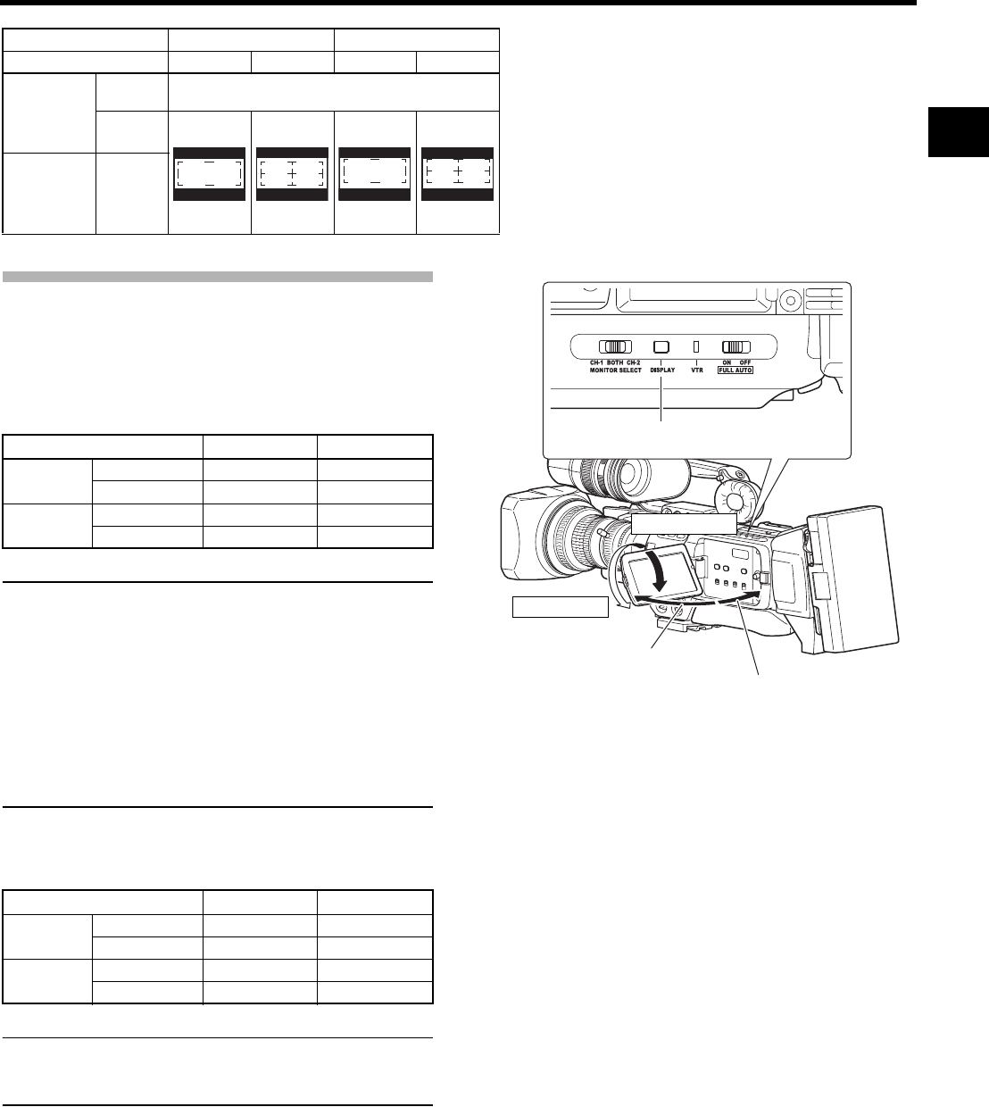
31
Switching between the LCD Screen
and Viewfinder Display
When the LCD+VF item in the LCD/VF[4/4] menu is set to
OFF, the LCD monitor and viewfinder (VF) displays are as
shown below.
MEMO
• You can switch between the LCD monitor and the view-
finder by holding down the DISPLAY button for about 2
seconds.
• After you set up the function that switches the display
between the LCD monitor and the viewfinder by holding
down the DISPLAY button, the display mode is cancelled
by the LCD monitor open/close and normal/inverted
operations.
• If the LCD monitor is closed inside this device with the
screen in the normal display orientation, holding down
the DISPLAY button does not work.
When the LCD+VF item in the LCD/VF[4/4] menu is set to
ON, the LCD monitor and viewfinder (VF) displays are as
shown below.
MEMO
• Press the DISPLAY button for 2 seconds to switch the
LCD screen display ON and OFF.
• The viewfinder screen is always displayed.
SAFETY ZONE 2.35:1CE 2.35:1CH
CENTER MARK OFF ON OFF ON
DV-60I
DV-50I
DV-24P
DV-24PA
DV-25P
4:3 Cannot be selected
16:9
HDV-HD60P
HDV-HD50P
HDV-HD30P
HDV-HD25P
HDV-HD24P
[16:9]
LCD Monitor Status LCD Display VF Display
LCD Closed Normal LCD OFF ON
Inverted LCD ON OFF
LCD Open Normal LCD ON OFF
Inverted LCD ON OFF
LCD Monitor Status LCD Display VF Display
LCD Closed Normal LCD OFF ON
Inverted LCD ON ON
LCD Open Normal LCD ON ON
Inverted LCD ON ON
DISPLAY button
Normal LCD
Inverted LCD
LCD open 40° or
more LCD close less
than 40°
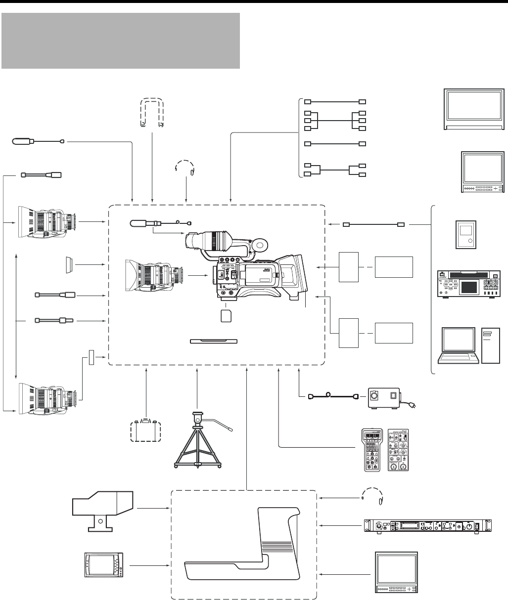
32
PREPARATIONS
Basic System
*1An HZ-FM13 cannot be used with a Th16 × 5.5BRMU or S14 × 7.3B12/U zoom lens.
Use a FUJINON focus manual unit (FMM-8, CFH-3, CFC-12-990).
For details, please consult your JVC authorized dealer.
MACRO
USER 3USER 2USER 1
STATUS
MENU
2
1
ND FILTER
REC
OFF
ON
POWER
WHT.BAL
AUTO
AUDIO
LEVEL
AUTO
CH-1 CH-2
VF BRIGHT
CALLTALLY
INTERCOM
LEVEL
FULL AUTO F1
SHUTTER
GAIN
F2
F3 MENU/SHUTTER GAIN PAINT AUTO
BR
W.BAL
AUTO
MANU
WHITE MASTER BLACK POWER
I
O
IRIS
STEP
SHUTTER
MENU PUSH-ON
DOWN UP
VARIABLE
PUSH-ON
HIGH
LOW
B
A
PRESET
CLOSE OPEN
MID
DOWN UP
F4
BARS
REMOTE CONTROL UNIT RM-P210
Shoulder Belt
Earphone
Microphone XLR 3P
Focus Manual Unit
*1 HZ-FM13 (FUJINON)
HZ-FM15 (CANON)
1/3 Zoom Lens
Th13 × 3.5BRMU (FUJINON)
Wide Converter
WCV-82SC
Focus Manual Unit
*1
Zoom Servo Unit
HZ-ZS13B
1/2 Zoom Lens
S14 × 7.3B12U (FUJINON)
S17 × 6.6BRM (FUJINON)
S20 × 6.4B12U (FUJINON)
YH16 × 7K12U (CANON)
YH19 × 6.7K12U (CANON)
2/3 Zoom Lens
Microphone
1/3 Zoom Lens
Th16 × 5.5BRMU (FUJINON)
(Excluding the CHU/CHE model)
GY-HD250/GY-HD251
Standard Package
Mount Converter
(1/2r1/3): ACM-12
(2/3r1/3): ACM-17
Carrying Case
GY-HD250/GY-HD251
SD Memory Card
XLR 4P
AC Adapter AC
Tripod
Dolly
Composite Cable
RCA pin
Audio Cable
RCA pin
Headset
DT109 (Beyerdynamic)
IEEE1394 Cable
6P-6P
Monitor
DV VTR
Non-linear Editing System
BR-HD50
Tripod Base (U model only)
For GY-HD251
Anton Bauer
Battery
Remote Control Unit
RM-LP55/RM-LP57
IDX
Battery Charger
HDD Unit
DR-HD100
Component Cable
BNC
View Finder
VF-P400
View Finder
DM-3106 (Astrodesign)
V-R70P-HAD (Marshall Electronics)
GY-HD250: Gold Mount
GY-HD251: V Mount
Battery mount
Monitor
Camera Remote Control Unit
RM-P210
HD-SDI Cable
BNC
Monitor
Studio Kit
KA-HD250
IDX (Endura)
Battery
Anton Bauer
Battery Charger
For GY-HD250
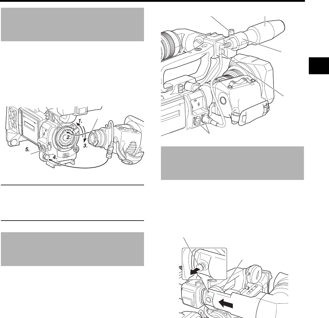
33
Attaching the Zoom Lens
1. Loosen the mount ring.
2. Attach the lens with its pin aligned with the hole in the
mount.
3. Tighten the mount ring.
4. Connect the cable connector.
5. Clamp the lens cable.
CAUTION
• Be sure to tighten the mount ring completely. Incomplete
tightening may result in the lens dropping off or disturbed
back focus.
• Set the GY-HD250/GY-HD251’s power switch to “OFF”
before the zoom lens is attached or detached.
Attaching the Microphone
(Provided)
Connect the provided microphone to the microphone holder.
Provided microphone is a phantom microphone.
1. Turn the knob on the microphone holder anticlockwise to
loosen it and open the microphone holder.
2. Place the microphone in the microphone holder.
Place the microphone toward the front to prevent it from
interfering with the cassette cover.
3. Turn the knob on the microphone holder clockwise to
secure the microphone.
4. Connect the microphone cable to the INPUT1 or INPUT2
input connector on the GY-HD250/GY-HD251.
5. Attach the microphone cable to the clamp.
6. Make sure to perform the correct setting for use of a
phantom microphone.
XSee page 56.
How to Attach the View-
finder
1. To attach the viewfinder, slide it in the direction of the
arrow.
2. Set the viewfinder to a comfortable position and then turn
the slide mounting ring and mount.
To take off the viewfinder, pull the knob in the direction of
the arrow as you slide the viewfinder.
Pin
Hole
Clamp
1. 3. Knob 2. Microphone
Microphone
holder
5. Clamp
4. INPUT1, 2 connector
Knob
Taking off the viewfinder
1.
2. Slide mounting ring
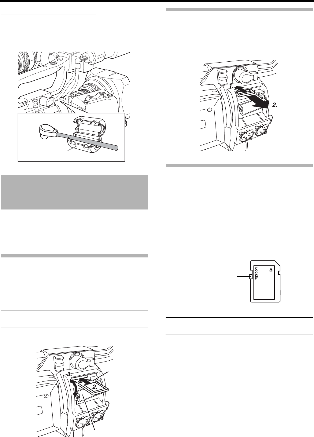
PREPARATIONS
34
About the Viewfinder Cable
Attach the viewfinder cable to the clamp 7 on page 14.
To reduce the emission of unwanted radio waves, be sure to
attach the provided core filter as shown in the figure below.
• Attach the core filter (black) as close to this device as pos-
sible, as shown in the figure.
Inserting an SD Memory
Card
By using an SD memory card, you can save and call up menu
settings and camera settings for GY-HD250/GY-HD251.
XSee “FILE MANAGE Menu Screen” on page 100.
Check that the POWER switch is OFF.
Inserting an SD Memory Card
1. Open the SD memory card cover.
2. Face the cutout end of the SD memory card inward and
insert it in the direction of the arrow.
CAUTION
Be sure not to touch the metal connector area of the SD
memory card.
3. Close the SD memory card cover.
Taking out the SD memory card
1. Push the SD memory card in the direction of the arrow.
• The SD memory card comes out slightly.
2. Pull the SD memory card straight out.
About SD Memory Cards
• When you use an SD memory card that was either just
purchased or formatted on a device other than GY-HD250/
GY-HD251, format it on GY-HD250/GY-HD251.
XSee page 102.
Recommended SD memory cards
Panasonic: 16 MB to 2 GB
• You can write-protect the card so that saved files are not
mistakenly erased. Set the switch on the side of the SD
memory card to the “LOCK” position.
MEMO
SDHC-compliant memory cards cannot be used with this
device.
Core filter (black)
SD memory card cover
Cutout
LOCK switch
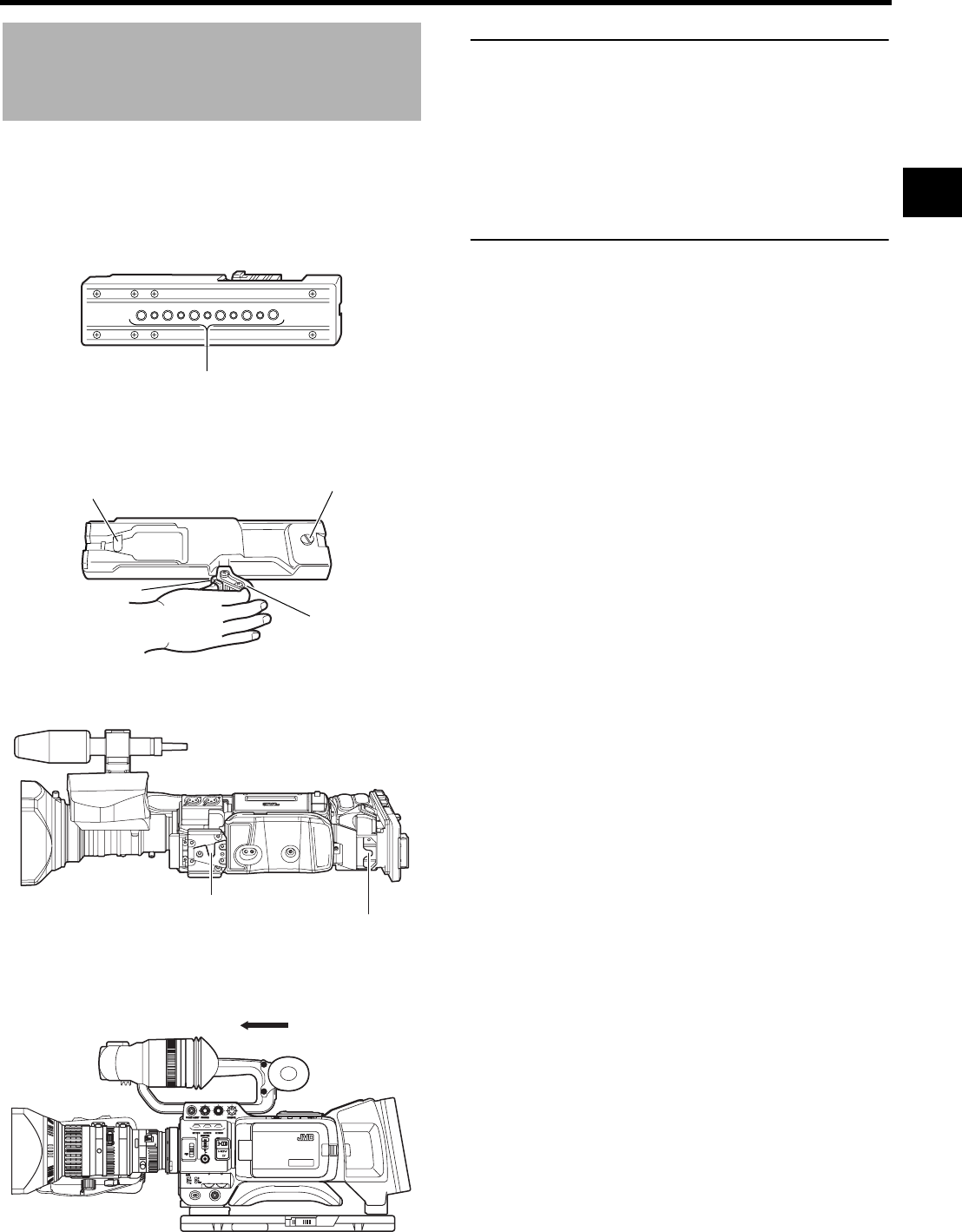
35
Attaching the Tripod Base
(Provided only for U model)
Use the provided tripod base to place the camera on a tri-
pod. (U model only)
1. Attach the tripod base on the tripod by using the hole that
balances this device most optimally.
2. While pushing the safety lever, pull the lock lever toward
the front until the front mount clip clicks into place.
3. Place this device on the tripod base by aligning the rear
base mount of this device with the pin on the tripod base.
4. Hold the camera on the top and slide forward so that the
base mount of the camera is locked by the front mount
clip of this device as it clicks into place.
CAUTION
• The front base mount may be locked while the pin of the
tripod base is not inserted into the hole on the rear base
mount of this device. Therefore, after mounting, make
sure that these parts are engaged properly.
• When moving this device mounted on a tripod, any
impact or vibration should be avoided as this may cause
this device to become detached and to drop from the tri-
pod.
Be sure to remove this device from the tripod before
transporting it.
1. Tripod mounting holes
Front mount clip
2. Safety lever
3. Pin
2.
Lock lever
4. Front base mount
3. Rear base mount
MACRO
USER 3USER 2USER 1
STATUS
MENU
2
1
ND FILTER
REC
OFF
ON
POWER
WHT.BAL
AUTO
AUDIO
LEVEL
AUTO
CH-1 CH-2
VF BRIGHT
4.
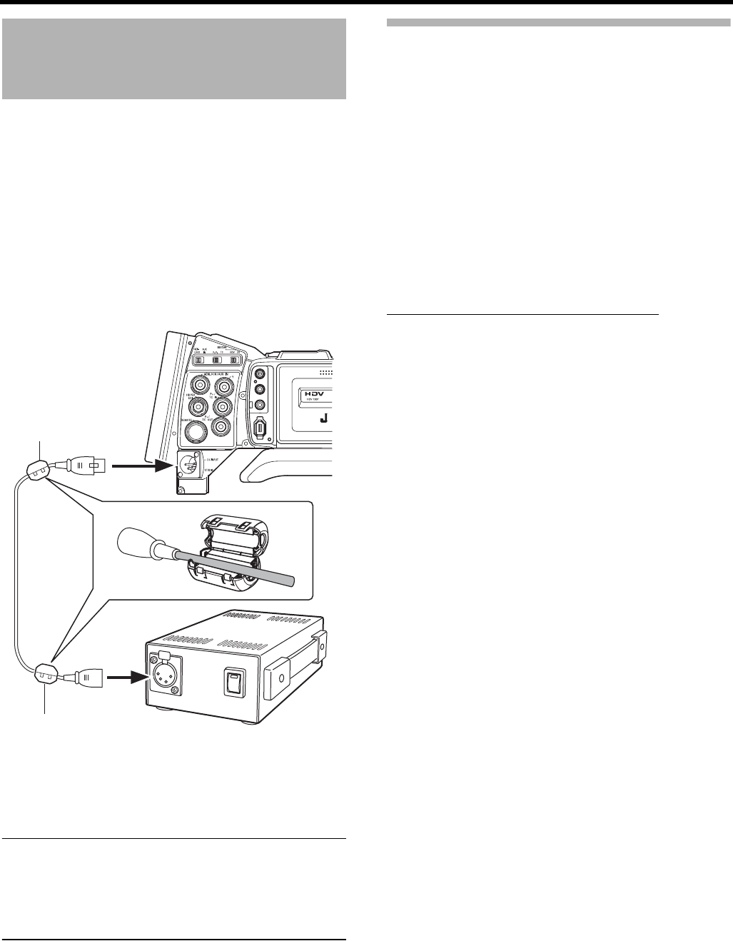
PREPARATIONS
36
AC Operation
The GY-HD250/GY-HD251 is operable with AC power supply
or battery pack.
Use the AC adapter as the AC power supply.
1. After making sure that the power switches of the GY-
HD250/GY-HD251 and of the AC adapter are set to OFF,
connect the DC cable to the DC OUTPUT connector of
the AC adapter and the DC INPUT connector of the GY-
HD250/GY-HD251 as shown in the illustration.
• To lessen the amount of unnecessary radio waves
emitted, attach a provided Clamp filter near both ends
of the DC cable as shown in the diagram.
2. Press the POWER switch of the GY-HD250/GY-HD251 to
ON. Power is supplied to the VTR section and the cam-
era.
CAUTION
• Do not remove or connect the DC cable while recording
is being performed.
• Do not use any power source with large fluctuations in
the power source voltage, power sources generating
noise, such as ripples or power sources with lower volt-
age.
Charging the Built-in Battery
The built-in, rechargeable backup battery retains the date
and time and the time code data.
The built-in battery is constantly being charge whenever the
GY-HD250/GY-HD251 is connected to a power supply, but it
gradually discharges while the GY-HD250/GY-HD251 is dis-
connected from a power supply. The battery will be fully dis-
charged when the GY-HD250/GY-HD251 is not used for
about three months, in which case the set date and time and
time code data are reset.
In this case, recharge the built-in battery and then set the
date and time and time code data again.
However, it is possible to use the GY-HD250/GY-HD251
even if the built-in battery is discharged but the date and time
and time code data cannot be recorded.
How to charge the built-in battery
1. Connect the AC adapter to the GY-HD250/GY-HD251
and an AC outlet or mount a charged battery on the GY-
HD250/GY-HD251.
2. Set the POWER switch on the GY-HD250/GY-HD251 to
“ON” or “OFF” (charging takes places with the POWER
switch set to either of the positions).
3. Leave the equipment in this condition for about 4 hours.
• The built-in battery will remain charged for about 3
months after being charged for about 4 hours.
IEEE 1394
CH2-AUDIO OUT-CH1 VIDEO
DC INPUT
AC adapter
DC OUTPUT
DC cable
Clamp filter
Clamp filter
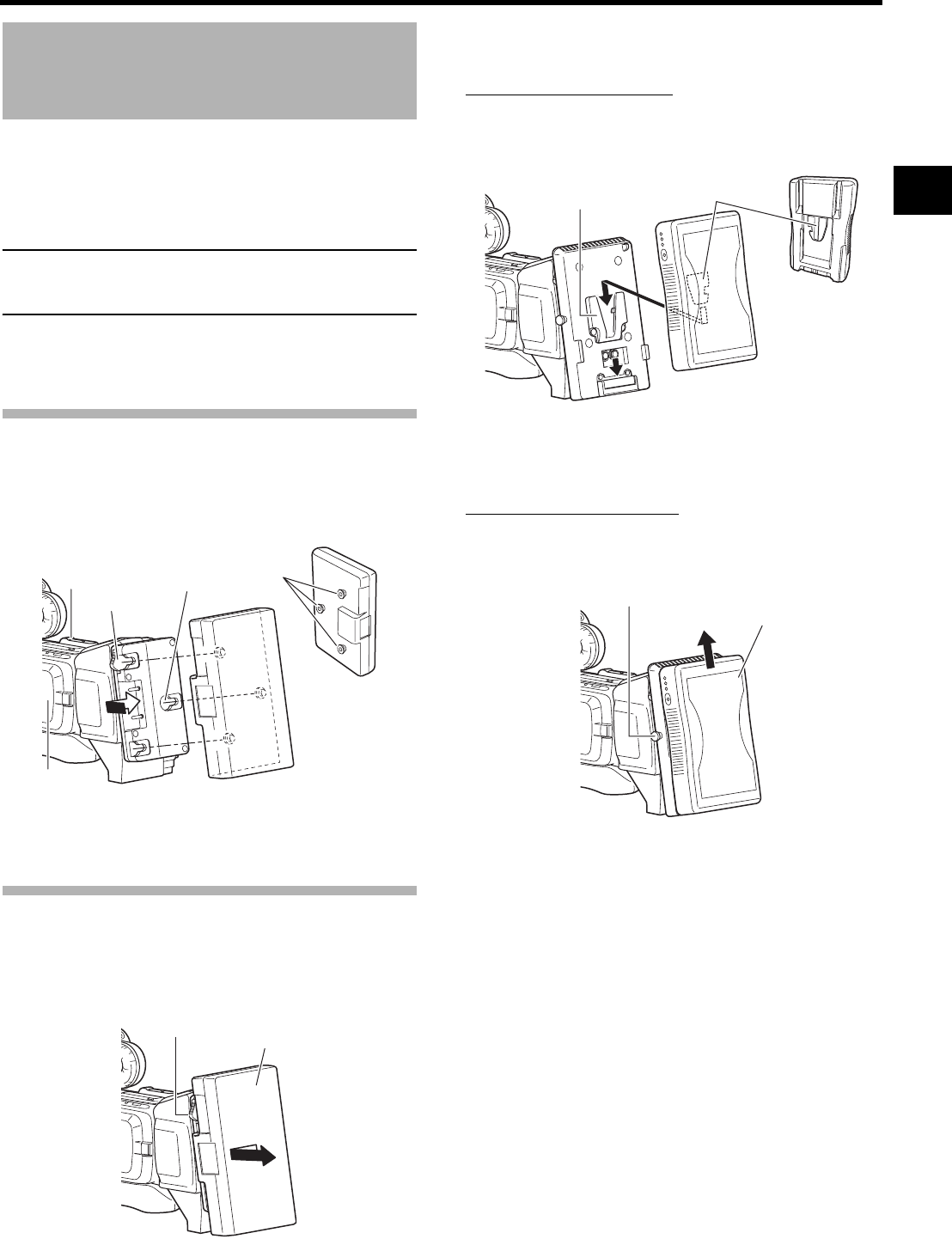
37
Battery Operation
The attachable battery varies depending on location.
Recommended batteries
U model: Dionic 90 (Anton Bauer)
E model: Endura-7 (IDX)
CAUTION
Use only the recommended batteries.
If a heavy battery is used, the battery may fall out depend-
ing on the way the HD camera recorder is used.
GY-HD250U
Use an Anton Bauer battery.
Attaching the Battery
1. Align the battery guide pins (three places) with the bat-
tery adapter guide holes and insert straight. Battery will
not be properly attached if guide pins are not straight.
2. Slide the battery towards the Cassette cover side panel
until it clicks.
• The battery is attached.
Removing the Battery
Slide the battery towards you (LCD screen side panel) while
holding down the release lever, and pull away from the
device to remove the battery.
GY-HD251E
Use an IDX (Endura) battery.
Attaching the Battery
1. Face the battery terminals down and align the battery V-
mount with the battery adapter V-mount attachment.
2. Slide the battery down until it clicks and locks.
• The battery is attached.
Removing the Battery
Slide the battery up while holding down the lock release but-
ton to remove the battery.
Release lever
Cassette cover
side panel
Guide
holes (×3)
LCD screen
side panel
Guide pins
Battery pack
(trim pack)
Release lever
Battery
V-mount
attachment V-mount
Release button
Battery
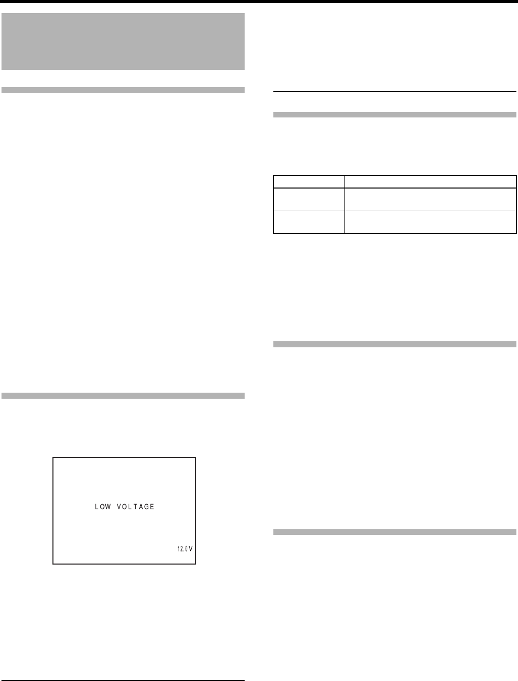
PREPARATIONS
38
Battery Operation
(Cont’d)
Precautions for the Battery Opera-
tion
• Do not detach the battery pack while recording is taking
place.
• Do not connect or disconnect the DC cable while operat-
ing with a battery pack.
The following symptoms may occur if the DC cable is con-
nected or disconnected while operating with a battery
pack.
• The power is cut off for a moment when the DC cable is
disconnected.
• Noise to the video and audio signals occurs. Audio sig-
nal are muted.
• When operation is continued with DC input after the bat-
tery pack capacity has been used up, set the POWER
switch to OFF after the DC power is applied. Then switch
ON again.
• If the GY-HD250/GY-HD251 is left with the battery pack
attached, a small amount of power is consumed even if
the POWER switch on the GY-HD250/GY-HD251 is set to
OFF.
Remove the battery pack when the GY-HD250/GY-HD251
is not going to be used.
Remaining Battery Power Display
When the remaining battery power is nearly exhausted, the
following warnings will be generated.
Viewfinder screen or LCD monitor
When a Status screen is displayed (excluding the STATUS
2, 3 screen in the Camera mode)
• Alarm indication: LOW VOLTAGE displayed.
FRONT and BACK TALLY lamp on camera: Blinks
Monitoring loudspeaker and PHONES jack: Alarm sound
MEMO
• After the remaining battery power warnings appear, the
GY-HD250/GY-HD251 automatically stops operation if
the battery power operation is continued.
• When you use an Anton Bauer battery, the remaining
battery (capacity or time) can be displayed in the STA-
TUS 1 screen of the LCD screen or viewfinder. Set BAT-
TERY INFO. on the LCD/VF[3/4] menu screen to
CAPA% or TIME to display the remaining battery. When
using the IDX Endura battery, the remaining capacity (%)
can be displayed. XSee page 91.
Operating Time with Battery Pack
When a fully charged battery pack is attached, the approxi-
mate continuous operating time is as follows
• Battery operating time may differ depending on the age of
the battery pack, charging conditions and the operating
environment, etc. Use the values in the table on the above
for approximate reference times.
• Operating time is reduced in areas with a cold environ-
ment.
• Operating time is reduced when the power zoom lens and
LCD are used frequently.
Precautions for the Battery Pack
• When the battery pack is not in use, it must be stored in a
cool, dry place.
Do not leave the battery pack in a place where it might be
subject to a high temperature (under direct sunlight in a
car, etc.), this could cause leakage of the fluid or shorten
service life.
• When the terminal section of the battery pack gets dirty,
the operating time will be shortened.
• If the operating time becomes greatly reduced even imme-
diately after recharging, the service life of the battery pack
is nearly finished.
Purchase a new battery pack.
Recharging
• Recharge the battery pack after completely discharging it.
Repeated recharging with residual charge remaining could
result in reduced battery capacity.
• If the battery capacity is reduced by repeating incomplete
recharging, or recharging without discharging, once dis-
charge the battery pack completely, then recharge it to
restore the battery capacity.
• If the battery pack is recharged with its internal tempera-
ture raised immediately after use, recharging may not be
performed completely.
• Perform charging in an environment where the tempera-
ture is between 10°C (50°F) and 35°C (95°F). 20°C (68°F)
to 25°C (77°F) is the ideal temperature range for charging.
If the environment is too cold, charging may not complete.
LCD monitor/Viewfinder
Battery Pack Continuous Operating Time (at 25°C (77°F))
Dionic 90
(U model)
Approx. 3.2 hours
Endura-7
(E model)
Approx. 2.5 hours
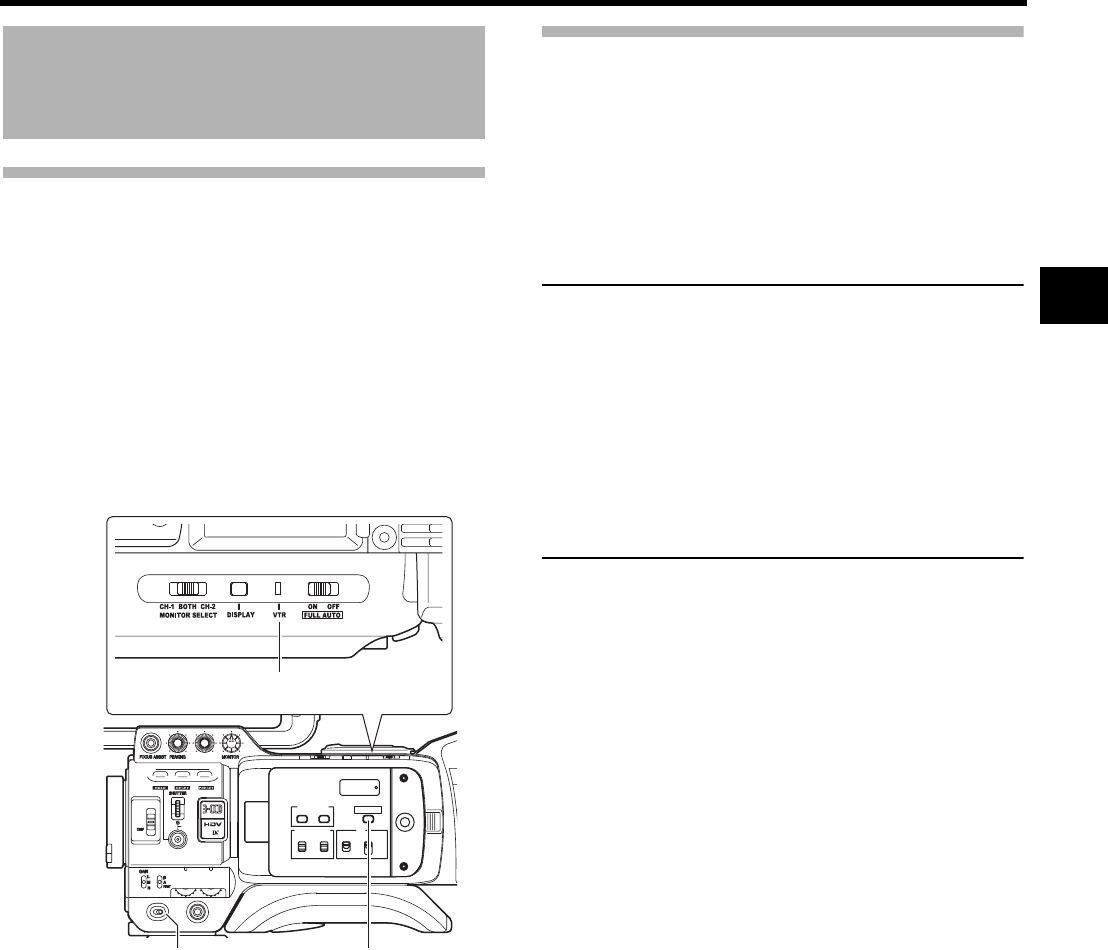
39
PREPARATIONS FOR OPERATION
Turning the Power ON
Turning the Power ON
1. Set the POWER switch to ON.
This device turns on in Camera mode.
The operation differs according to whether this device is in
the Camera mode or in the VTR mode.
The mode switches each time you press the CAM/VTR button.
When the mode is switched, the VTR indicator displays
the following statuses.
Camera mode
The GY-HD250/GY-HD251 enters the Camera mode. The
camera image is displayed in the viewfinder or on the LCD
monitor. When a recordable videocassette is loaded, the
GY-HD250/GY-HD251 enters the record-standby mode
automatically. “STBY” is displayed in the VTR operation
mode indication area of the LCD monitor and/or in the
viewfinder. In this condition, press the REC/VTR trigger
button to start recording.
* Playback is also possible in the Camera mode.
Playback operation becomes possible when the STOP
button is pressed to set the VTR operation mode indica-
tor to indicate “STOP”.
VTR mode
The GY-HD250/GY-HD251 enters the VTR mode. The
camera image will not be displayed in the viewfinder or on
the LCD monitor. When a videocassette is loaded, the GY-
HD250/GY-HD251 enters the stop mode.
“STOP” is displayed in the VTR operation mode indication
area of the LCD monitor and/or in the viewfinder.
HDV/DV input is possible through the IEEE1394 connector.
Turning the Power OFF
1. Place the GY-HD250/GY-HD251 in the record-standby or
STOP mode.
2. Set the POWER switch to OFF.
3. Remove the battery pack or the power supply to the DC
INPUT connector. (When the camera is not going to be
used for a longer period.)
CAUTION
• Do not set the POWER switch to OFF while recording is
taking place.
Confirm that the “STBY” or “STOP” indication is shown in
the VTR operation mode indication area before the
power is turned off.
Should the POWER switch accidentally be set to OFF
during a recording, wait at least 5 seconds before turning
the power on again.
• Always set the POWER switch to OFF before discon-
necting the power supply.
Do not remove the battery pack or turn AC adapter OFF
while the POWER switch on the camera is still set to ON.
While the mode is being switched : Flashing
In VTR mode : Lit
In Camera mode : Off
USER 3USER 2USER 1
STATUS
MENU
2
1
ND FILTER
REC
OFF
ON
POWER
WHT.BAL
AUTO
AUDIO
LEVEL
AUTO
CH-1 CH-2
VF BRIGHT
CH-2
CH-1
-
+
AUDIO SELECT
MANU
AUTO
TC
LCD BRIGHT
DISPLAY
TC
UB
FREE
REGEN
GENE.
REC
CAM/VTR
VTR indicator
POWER switch CAM/VTR button
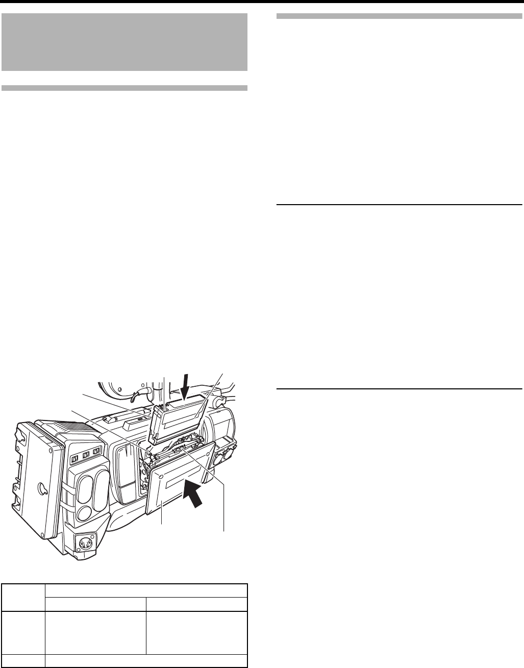
PREPARATIONS FOR OPERATION
40
Loading/Unloading the
Cassette
Cassette Loading
Use a videocassette tape marked MiniDV.
• To record, slide the switch on the back for use in prevent-
ing accidental erasure to the “REC” side.
• Remove any the tape slack before loading.
1. Turn the POWER switch ON.
2. Slide the EJECT switch on the top panel of this device to
the side.
The videocassette cover opens automatically and a vid-
eocassette tape can be inserted.
3. Insert a videocassette tape into the videocassette holder.
With the tape window facing out, move the switch on the
back of the videocassette up and firmly push the center
back of the videocassette straight in as far as it will go.
4. Carefully push the center (“Push here” sticker) of the vid-
eocassette cover in the direction of the arrow as far as it
will go to close it.
• After the cover is closed, it takes about 10 seconds
until recording can begin or this device can enter
STOP mode.
If the power is on, the modes are as shown below.
Unloading the Cassette
1. Turn the POWER switch to ON.
2. When this device is in shooting standby mode or stop
mode, slide the EJECT switch to the side and wait until
the videocassette cover opens completely.
• The LED next to the EJECT switch flashes.
A few seconds pass before the videocassette tape is
ejected.
3. The LED turns off and the videocassette cover opens.
• Take out the videocassette tape.
4. Carefully push the center of the videocassette cover in
the direction of the arrow as far as it will go to close it.
CAUTION
• When you close the videocassette cover, push it in firmly
as far as it will go. If the videocassette cover is not closed
properly, it becomes half-locked and this device cannot
function.
If this happens, firmly push the videocassette cover in
again as far as it will go to lock it.
• The videocassette cover does not open during recording
even if you slide the EJECT switch.
• Do not leave the videocassette cover open for a long
time.
Dust or dirt may enter the inside and cause damage.
• Do not touch the videocassette cover or interfere with the
eject operation while ejecting is in progress. This will
cause damage.
• When you close the videocassette cover, do not press
the black area of the inner cover.
MODE REC/SAVE switch
REC SAVE
Camera Record-standby mode STOP mode
REC INHIBIT is displayed
on the LCD monitor and in
the viewfinder.
VTR STOP mode
REC/SAVE
switch Tape window
EJECT switch
Cassette holder
Videocassette cover Inner cover

41
Setting and Displaying the
Date and Time
The date and time of the built-in clock should be set. Pow-
ered by the built-in backup battery the set date and time data
continue to count even when the power is switched off.
• The set date and time data are displayed on the LCD mon-
itor or in the viewfinder and recorded on the tape in accor-
dance with the settings made on the menu screen.
Setting the Date and Time Style
The date and time are set on the menu screen.
When setting while observing on a monitor connected to the
connector, set the ANALOG OUT CHAR. item or SDI OUT
CHAR. item on the OTHERS[1/2] menu screen to ON.
1. Set the POWER switch to ON.
2. Press the STATUS button for 1 second or longer to dis-
play the TOP MENU screen.
3. Rotate the SHUTTER dial to align the cursor (K) with the
TC/UB/CLOCK item, and then press the SHUTTER dial
in the direction of the camera body.
• The TC/UB/CLOCK menu screen appears.
4. Rotate the SHUTTER dial to align the cursor (K) with the
TIME/DATE item, and then press the SHUTTER dial.
• The TIME/DATE menu screen appears.
• Set the DISPLAY item on the TIME/DATE menu
screen to ON.
5. Make settings on the TIME/DATE menu screen. (This
includes display style, etc.)
1Rotate the SHUTTER dial to align the cursor (K) with
the item to be set, and then press the SHUTTER dial.
• The setting area of the selected item starts blinking.
2Rotate the SHUTTER dial to change the setting, and
then press the SHUTTER dial.
• The setting area stops blinking and the setting is
entered.
MEMO
The TIME STYLE, SEC DISPLAY, DATE STYLE and TIME
SHIFT items can also be set and changed after the date
and time have been set.
USER 3USER 2USER 1
STATUS
MENU
2
1
ND FILTER
REC
OFF
ON
POWER
WHT.BAL
AUTO
AUDIO
LEVEL
AUTO
CH-1 CH-2
3.
1. POWER switch
SHUTTER dial
2.
STATUS button
DATE STYLE : Selects the style for displaying the
date.
YY/MM/DD (Year, month, day)
MM/DD/YY (Month, day, year)
DD/MM/YY (Day, month, year)
TIME STYLE : The time can be set to display as a 12-
hour or 24-hour clock system.
SEC DISPLAY : To select whether or not indication of
seconds should be displayed on the
screen.
TIME SHIFT : Adds time to the built-in clock (time
compensation) and displays it. The
adjusted time is also recorded on the
tape.
TC/UB/CLOCK menu screen
TIME/DATE menu screen
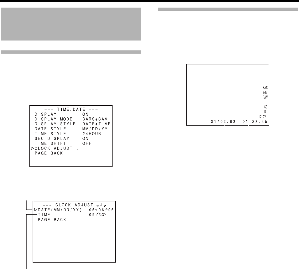
PREPARATIONS FOR OPERATION
42
Setting and Displaying the Date
and Time (Cont’d)
Setting the Date and Time
1. Display the CLOCK ADJUST menu screen.
Select the CLOCK ADJUST item on the TIME/DATE
menu screen.
2. Set the date and time.
The blinking digit is the one to be set.
1When the SHUTTER dial is pressed, the blinking digit
moves to the next digit.
2When the SHUTTER dial is rotated, the value of the
blinking digit changes.
When the SHUTTER dial is rotated upward, the value
becomes higher. When rotated downward, the value
becomes smaller.
3Repeat the procedure described in 1 and 2 above to
set the day, month, year, hours, minutes.
The digits indicating seconds cannot be set.
4Press the SHUTTER dial in sync with a time signal to
enter the date and time precisely.
3. When all the settings are completed, rotate the SHUT-
TER dial to align the cursor with the PAGE BACK item,
and then press the SHUTTER dial.
• The TIME/DATE menu screen returns.
4. To return to the normal screen, use either of the following
methods.
Press the STATUS button
or
Return to the TOP MENU screen and then select the
EXIT item on the TOP MENU screen before pressing the
SHUTTER dial.
Displaying the Time and Date on the
Screen
Whether or not the time and date should be displayed on the
screen and how to display them are set on the TIME/DATE
menu screen.
1. Display the TIME/DATE menu screen.
1
Select the TC/UB/CLOCK item on the TOP MENU
screen.
2Select the TIME/DATE item on the TC/UB/CLOCK
menu screen.
2. Set the TIME/DATE menu screen.
Display of date and time in the various operation modes.
TIME/DATE menu screen
Date
Time (Hour:Min)
CLOCK ADJUST menu screen
• DISPLAY item : Sets whether or not date and time
should be displayed.
Set to ON to display the indications.
• DISPLAY MODE
item
: Sets the video output mode in
which date and time should be dis-
played.
BARS :
Displayed when outputting the color
bar.
CAM : Displayed when outputting the color
camera image.
BARS+CAM :
Date and time are always displayed.
• DISPLAY
STYLE item
: Sets the style in which the date and
time are displayed.
DATE+TIME : Date and time are displayed.
DATE : Date only is displayed.
TIME : Time only is displayed.
In Camera mode : The date and time of the internal
clock are displayed.
In VTR playback mode : The date and time recorded on the
tape are displayed.
In VTR stop mode : The last read date and time values
are displayed.
When an HDV/DV sig-
nal is input from the
IEEE1394 connector
: The date and time of the DV input
are displayed in DV format. The
date and time of the internal clock
are displayed in HDV format.
Date Time
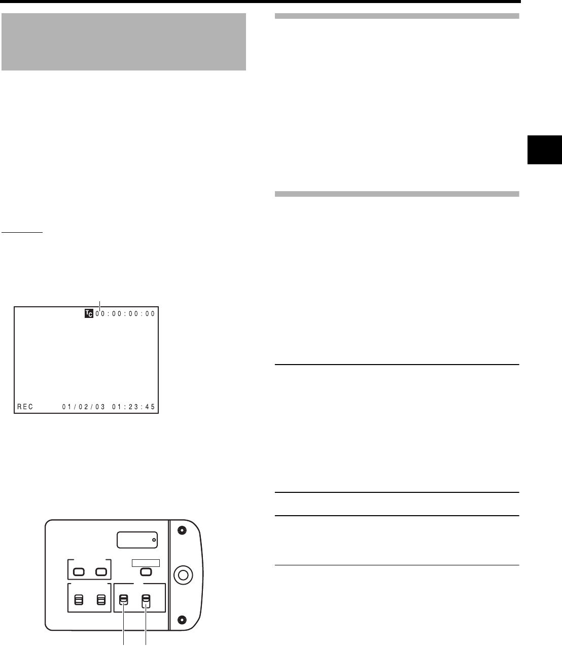
43
Displaying Time Code
The GY-HD250/GY-HD251 records SMPTE-standard
(NTSC) or EBU-standard (PAL) time codes and user’s bits.
In the play mode or the record mode, the reproduced time
codes or user’s bits are shown on the LCD monitor or in the
viewfinder.
• Time code generator data is output from the [TC OUT] ter-
minal or [HD/SD-SDI] terminal.
The time codes or user’s bits can be shown on the LCD mon-
itor or in the viewfinder during playback and recording as fol-
lows. (Status screen)
Setting
1. Set the TC/UB item on the LCD/VF[3/4] menu screen to
ON.
• Time codes or user’s bit data are displayed on the
STATUS screen.
2. Whether time codes or user’s bit data should be dis-
played is selected with the TC DISPLAY switch inside the
LCD door.
Displayed Time Code/User’s Bit
• When TCG SOURCE on the TC/UB/CLOCK menu screen
is set to INTERNAL, values from the built-in time code
generator is displayed.
• When TCG SOURCE on the TC/UB/CLOCK menu screen
is set to EXTERNAL, values from the external time code
generator connected to the [TC IN] terminal is displayed.
• When TC DUPLI. on the TC/UB/CLOCK menu screen is
set to ON in IEEE1394 input mode, values input in the
[IEEE1394] terminal is displayed.
• Values recorded on the tape are displayed for PLAY
mode.
Time code input entered the
IEEE1394 connector
Pressing the STOP button for 1 second in the EJECT or stop
mode displays the DV input time code data or user’s bit data
from the IEEE1394 connector on the STATUS screen.
To return to display of the original time code or user’s bit,
press the STOP button. (Display of the normal time code or
user’s bit is also restored by performing VTR operation.)
MEMO
• To use input time code data from the IEEE1394 terminal,
set TCG SOURCE item on the TC/UB/CLOCK menu
screen to INTERNAL.
• To record HDV/DV input time code and user’s bit from
the IEEE1394 connector, set the TC DUPLI. item on the
TC/UB/CLOCK menu screen to ON.
XSee page 93.
• To maintain the continuity of time code data, use with the
TC GENE. switch set to REGEN mode when recording
HDV/DV input signal from the IEEE1394 connector.
• There is no time code display for HDV input.
CAUTION
A time code with a duration of more than 2 hours may not
be displayed correctly by DV components for general con-
sumer use, as some of these lack the capability to display
longer time codes.
TC : Time codes are displayed.
UB : User’s bit data is displayed.
Time code indication
(Example)
Time code indication
00:00:00:00
User’s bits indication
FF EE DD 20
STATUS 1 screen
CH-2
CH-1
-
+
AUDIO SELECT
MANU
AUTO
TC
LCD BRIGHT
DISPLAY
TC
UB
FREE
REGEN
GENE.
REC
CAM/VTR
TC DISPLAY switch TC GENE. switch
DTCG : The time code data from the IEEE1394 connector
DUBG : The user’s bit data from the IEEE1394 connector
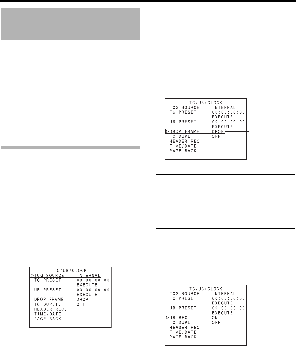
PREPARATIONS FOR OPERATION
44
Presetting and Recording
of Time Code
The time codes from the internal time code generator can be
recorded at the time of recording scenes.
• The TC/UB/CLOCK menu screen differs depending on
whether the FRAME RATE item on the VIDEO FORMAT
menu screen is “60/30” or “50/25”.
There are two ways to preset the time code.
• Set from the TC/UB/CLOCK menu screen.
• Set in the LCD screen without opening the menu screen.
This section explains how to set from the TC/UB/CLOCK
menu screen.
* See page 46 for instructions of setting from the LCD
screen.
Menu and switch settings to set the time code preset are the
same as the settings below.
Setting
To preset the Time Code, make the following settings.
TC GENE. switch
Set to REC or FREE.
Set the TCG SOURCE item in the TC/UB/CLOCK menu
screen to INTERNAL.
TC/UB/CLOCK menu screen (FRAME RATE: 60/30)
Use the DROP FRAME item to select the framing mode
for the time code generator.
MEMO
Drop frame/Non-drop frame mode
In the NTSC system, the actual number of frames per 1
second is approximately 29.97 frames, but per time code
30 frames are processed. To compensate for this differ-
ence, the mode called “drop mode” drops frame 00 and 01
for every minute not divisible by 10.
The “non-drop frame mode” is when no frames are dropped
and the actual time shift neglected.
TC/UB/CLOCK menu screen (FRAME RATE: 50/25)
Whether or not user’s bit data should be recorded can be
selected with the UB REC item on the TC/UB/CLOCK
menu screen.
REC : The data preset in the time code generator
runs only during recording.
Use this setting if it is necessary to record
continual time codes across different scenes.
* However, approximately ±1-frame varia-
tions may occur in scene accuracy.
FREE : The time code starts to run from the time it is
preset in the time code generator.
DROP : The time code generator’s running method is
set the drop frame mode.
Use this setting when placing emphasis on
the recording time.
NON
DROP
: The time code generator’s running method is
set to the non drop frame mode.
Use this setting when placing emphasis on
the number of frames.
TC/UB/CLOCK menu screen
(FRAME RATE: 60/30)
Framing mode:
Drop frame/
Non-drop setting
TC/UB/CLOCK menu screen
(FRAME RATE: 50/25)
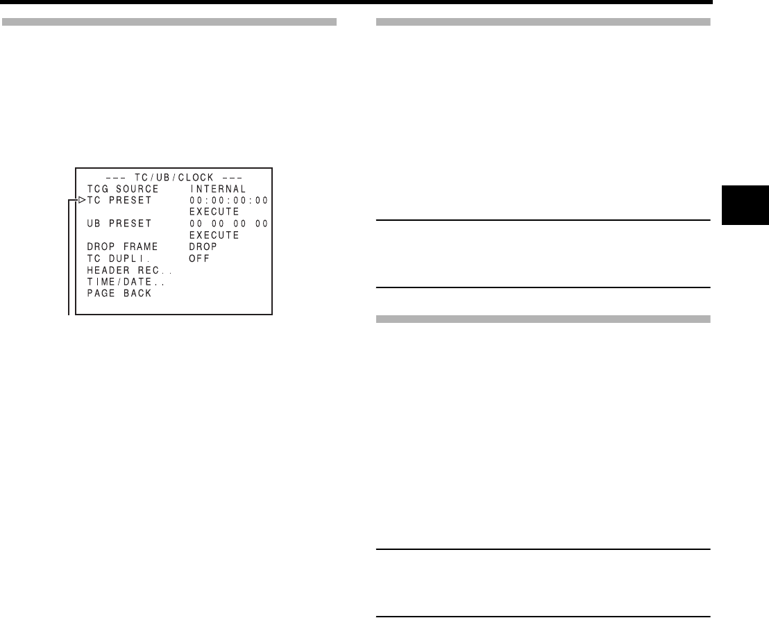
45
Presetting time code data
The time code and user’s bit data are preset on the TC/UB/
CLOCK menu screen.
1. Display the TC/UB/CLOCK menu screen.
Select the TC/UB/CLOCK item on the TOP MENU
screen.
2. Set the time code (hours, minutes, seconds, frames).
1Rotate the SHUTTER dial to align the cursor (K) with
TC PRESET, and then press the SHUTTER dial.
• The first digit of the time code blinks.
The blinking digit is the one to be set.
2When the SHUTTER dial is pressed, the blinking digit
changes.
3When the SHUTTER dial is rotated, the value of the
blinking digit changes.
When the SHUTTER dial is rotated upward, the value
becomes higher. When rotated downward, the value
becomes smaller.
4Repeat the procedure described in 2 and 3 above to
set the desired value for all digits.
5After setting the frame digit, press the SHUTTER dial to
make EXECUTE blink. The setting values are con-
firmed when the SHUTTER dial is pressed again.
To cancel the setting, select CANCEL and press the
SHUTTER dial.
3. When all the digits are set
• Press the STATUS button to return to the normal
screen
or
• Rotate the SHUTTER dial to align the cursor (K) with
the PAGE BACK item, and then press the SHUTTER
dial to return to the TOP MENU screen.
Presetting user’s bit data
The user’s bit data are preset with the UB PRESET item on
the TC/UB/CLOCK menu screen.
The method for setting is the same as the method for setting
the time code described on the left.
• The user’s bit can be specified using numerals or alpha-
betic letters from 0 to F for each digit.
• To record user’s bit data, set the UB REC item to ON (Only
when set to FRAME RATE 50/25).
CAUTION
It is not possible to set all the digits of the user’s bit data to
“F”.
Reading of the data during playback will not be possible for
an all-F setting.
Zero-resetting the Time Code or
User’s Bit Data
This is performed with the TC or UB PRESET item on the
TC/UB/CLOCK menu screen. (Performed separately for the
time code and the user’s bit data.)
1Rotate the SHUTTER dial to align the cursor (K) with the
TC or UB PRESET item, and then press the SHUTTER
dial.
2Rotate the SHUTTER dial to select ZERO PRESET as the
setting value, and then press the SHUTTER dial.
MEMO
When a menu screen is not being displayed, you can zero
reset the time code data by simultaneously holding down
the USER2 button and the STOP button for about 1 sec-
ond.
Time code (hour, min, sec, frame)
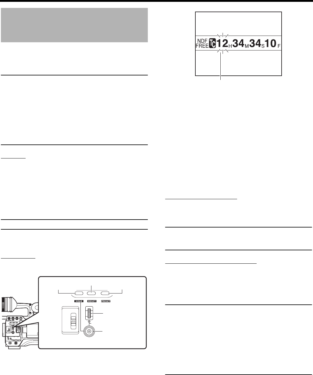
PREPARATIONS FOR OPERATION
46
Presetting the Time Code
from the LCD Screen
The time code can be preset directly from the LCD screen
without opening the TC/UB/CLOCK menu screen.
CAUTION
PRESET mode is not available in the following.
• TCG SOURCE item in the TC/UB/CLOCK menu screen
is set to EXTERNAL.
• TC GENE. switch is set to REGEN.
• TC DUPLI. item in the TC/UB/CLOCK menu screen is
set to ON.
• Menu screen is displayed.
• RECORDING mode is active.
• Switching to CAM/VTR mode (When VTR indicator is
blinking).
Setting
TC/UB/CLOCK menu screen
• Set TCG SOURCE to INTERNAL.
• Set framing of the time code generator in DROP
FRAME. (When set to FRAME RATE 60/30)
• Set to enable/disable user’s bit recording in UB REC.
(When set to FRAME RATE 50/25)
Set the TC GENE switch to REC or FREE.
MEMO
See page 44 for details on the above settings.
Set the TC DISPLAY switch.
Set to TC to preset time code and UB to preset user’s bit.
Operation
This section describes presetting of the time code.
1. In Standby or Stop mode, press the USER1 button for
about 2 seconds while holding down the STATUS button.
• The current time code generator data is displayed in
enlarged display mode on the LCD screen. The hour
digit starts blinking.
2. Press the USER2 button to reset all data.
• Data becomes “00:00:00:00” and the hour digit starts
blinking.
3. Set the time code (hour, minute, second and frame).
The blinking digit can be set.
1Turn the SHUTTER dial to change the value of the
blinking digit. Turn the SHUTTER dial up to increase the
value and down to decrease the value.
2Press the SHUTTER dial to change the blinking digit.
3Repeat steps 1 and 2 and continue setting for each
row.
4. Press the USER3 button to confirm the setting data.
• The LCD screen returns to the original screen.
Presetting User’s Bit
You can specify the user’s bit with a number or character
between 0 - F.
CAUTION
All digits of user’s bit cannot be set to F.
If all digits are set to F and read, user’s bit is deemed as
undefined during playback.
Aborting Preset Operation
While presetting, press the USER1 button while holding
down the STATUS button.
• Preset operation stops and the LCD screen returns to
the original screen.
CAUTION
Preset operation is terminated in the following.
• TC DISPLAY switch is changed
• CAM/VTR mode switch is changed
• VTR operations are performed
USER1, USER2, and USER3 presetting in the SWITCH
MODE menus screen is not available when the Time Code
Preset screen is displayed.
The time code preset screen is displayed on the LCD
screen or viewfinder. It will not be output from the VIDEO
OUT terminal.
USER 3USER 2USER 1
STATUS
MENU
2
1
ND FILTER
REC
OFF
ON
POWER
WHT.BAL
AUTO
AUDIO
LEVEL
AUTO
CH-1 CH-2
VF BRIGHT
USER 3USER 2USER 1
STATUS
SHUTTER
MENU
2
1
ND FILTER
OFF
USER 1 button USER 2 button USER 3 button
SHUTTER dial
STATUS button
Blink
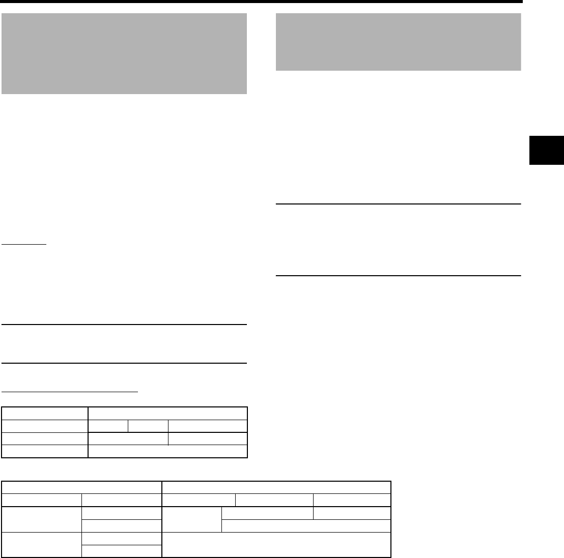
47
Recording Time Codes in
Continuation of Time
Codes Recorded on Tape
The GY-HD250/GY-HD251 also incorporates a time code
reader. Therefore, when this device enters record mode from
record-standby mode, it can read the time code data
recorded on the tape and record time codes in continuation
of the existing data.
The recorded user’s bit data are identical to the user’s bit
date recorded on tape.
* However, approximately ±1-frame variations may occur in
scene accuracy.
To enable this function, set the time code related switches as
follows before starting recording.
Setting
• Set TCG SOURCE on the TC/UB/CLOCK menu screen to
INTERNAL.
• Set the TC GENE. switch inside the LCD door to REGEN.
• Set TC DUPLI. item on the TC/UB/CLOCK menu screen
to OFF.
MEMO
The time code framing mode automatically becomes the
mode (drop frame or non drop frame) already recorded on
the tape.
Playing Back Time Code
This device features a time code reader. During playback,
the time code or user’s bit data recorded on the tape is dis-
played on the LCD screen or viewfinder status screen.
• When the [PB/PR/TC] switch is set to TC, the playback
time code is output from the [PB/TC OUT] terminal (Only in
VTR mode).
• When HD/SD-SDI OUT of the VIDEO FORMAT[2/2] menu
screen is set to ON, the playback time code is output from
the [HD/SD-SDI] terminal.
MEMO
• During playback, if a portion of tape without recording
time code runs through, the time code stops running.
Playback continues.
• When a tape with a time code that is longer than two
hours is played on home-use DV equipment, time code
may not be played properly on some models.
About Time Code Mode
Camera mode
VTR mode/IEEE1394 input mode
*IEEE1394 TC SLAVE mode is performed with special operations. XSee page 48.
TC/UB/CLOCK menu TC GENE. switch
TCG SOURCE item FREE REC REGEN
INTERNAL TC PRESET mode TC REGENE mode
EXTERNAL EXT TC mode
TC/UB/CLOCK menu TC GENE. switch
TCG SOURCE item TC DUPLI. item FREE REC REGEN
INTERNAL OFF IEEE1394 TC
SLAVE mode*
TC PRESET mode TC REGENE mode
ON IEEE1394 TC DUPLI. mode
EXTERNAL OFF EXT TC mode
ON
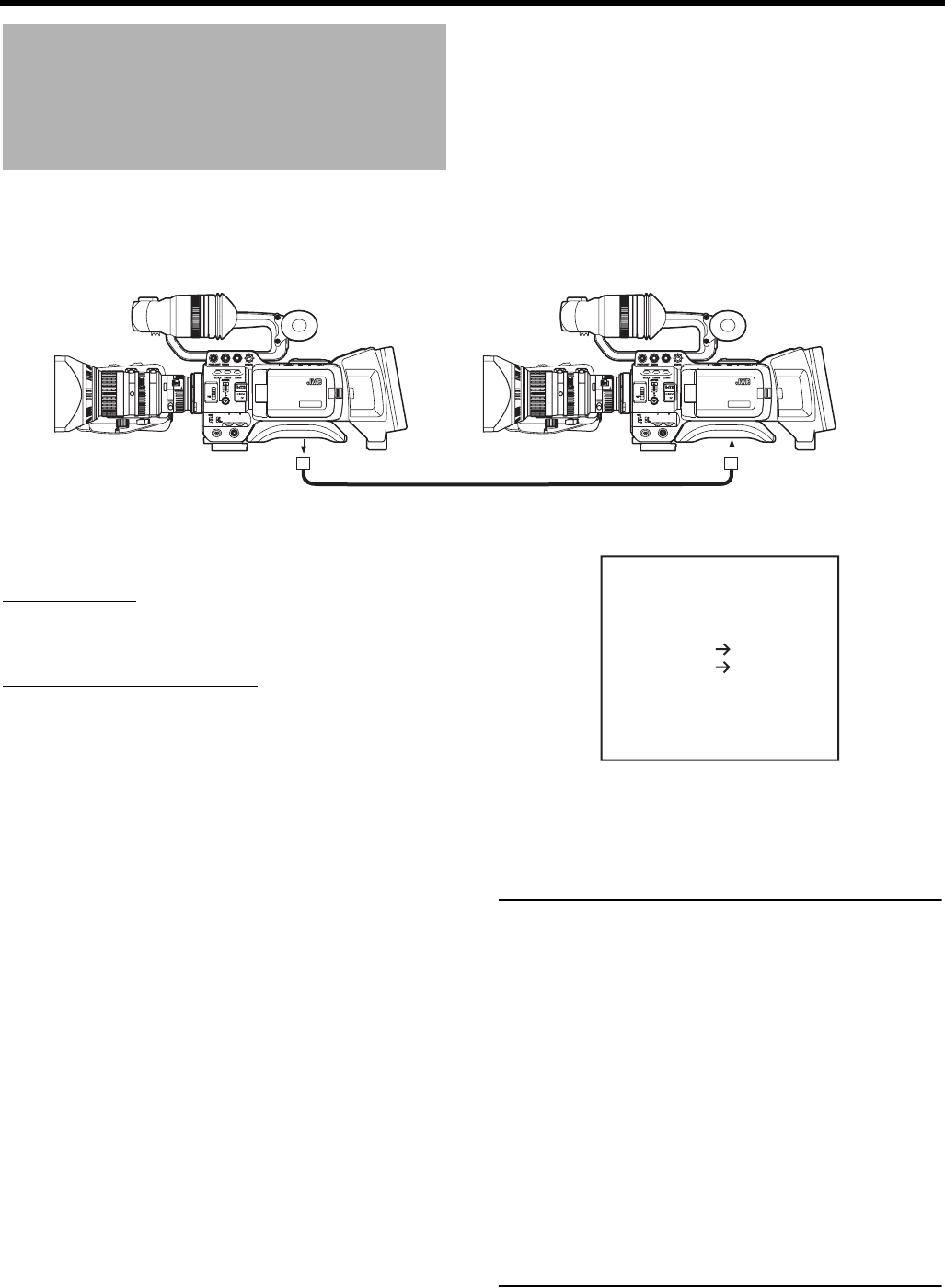
PREPARATIONS FOR OPERATION
48
Synchronizing with the
Time Code of the IEEE1394
(DV)-Connected Master Unit
You can synchronize the time code when performing multi-camera recording. The internal time code generator will be synchro-
nized with the time code in the signal input from the IEEE1394 terminal. After synchronization (slave lock), the internal time code
generator continues to run even if the IEEE1394 cable is disconnected.
You can use the GY-HD250U, GY-HD251E, GY-HD110U, or
GY-HD111E as a slave unit.
Connections
Connect the master unit and the slave unit with an IEEE1394
cable.
Settings and Operations
• Master unit (GY-HD100U/GY-HD100E/GY-HD101E/GY-
HD110U/GY-HD110E/GY-HD111E/GY-HD250U/GY-
HD251E)
1. Set the IEEE1394 switch on the left side to [DV].
2. Set to Camera mode.
3. Set the recording format to DV-60I or DV50I.
4. Set the TC GENE. switch to [FREE].
• Slave unit (GY-HD250U/GY-HD251E/GY-HD110U/GY-
HD111E)
1. Set the IEEE1394 switch on the left side to [DV].
2. Set to VTR mode.
3.
Check that the camera image from the master unit is input.
4.
Set TCG SOURCE in the TC/UB/CLOCK menu screen to
INTERNAL. (GY-HD250U, GY-HD251E)
5. Set the TC GENE. switch to [FREE] and the TC DISPLAY
switch to [TC].
6. Set to STOP mode or EJECT mode.
7. Press the STOP button for 1 second.
• The DV input time code data from the IEEE1394 termi-
nal is displayed in the status display. (When status is in
magnified size, characters are displayed.)
8. Press the USER1 button to begin slave lock.
(To skip slave lock, press the USER3 button and clear
the status display.)
9. Check that the time code that is synchronized with the
master unit is running.
10.Disconnect the IEEE1394 cable.
11.The slave unit finally returns to Camera mode.
MEMO
Slave lock cannot be performed in the following
instances.
• Slave unit is in CAMERA mode
• Slave unit is in VTR mode and there is no DV signal
• The TC GENE. switch on the slave unit is not set to
FREE
• HDV format
If slave lock is performed in DV format and is then
switched to HDV format, frame digit may deviate.
If power is turned off, slave lock is disabled. Perform
slave lock operation again.
Slave lock cannot be performed for UB (User’s bit).
If the frame rate for the master unit and slave unit is not
synchronized, it will not run properly. Synchronize frame
rate before using.
If DROP/NON DROP is not synchronized, it will not run
properly. Synchronize DROP/NON DROP before using.
MACRO
USER 3USER 2USER 1
STATUS
MENU
2
1
ND FILTER
REC
OFF
ON
POWER
WHT.BAL
AUTO
AUDIO
LEVEL
AUTO
CH-1 CH-2
VF BRIGHT
MACRO
USER 3USER 2USER 1
STATUS
MENU
2
1
ND FILTER
REC
OFF
ON
POWER
WHT.BAL
AUTO
AUDIO
LEVEL
AUTO
CH-1 CH-2
VF BRIGHT
Master unit Slave unit
IEEE1394 cable
IEEE1394 terminal IEEE1394 terminalSlide the IEEE1394
switch to the [DV] side.
Slide the IEEE1394
switch to the [DV] side.
DTCG
TC SLAVE LOCK ?
EXECUTE USER1
00 : 00 : 00 : 00
CANCEL USER3
Status display
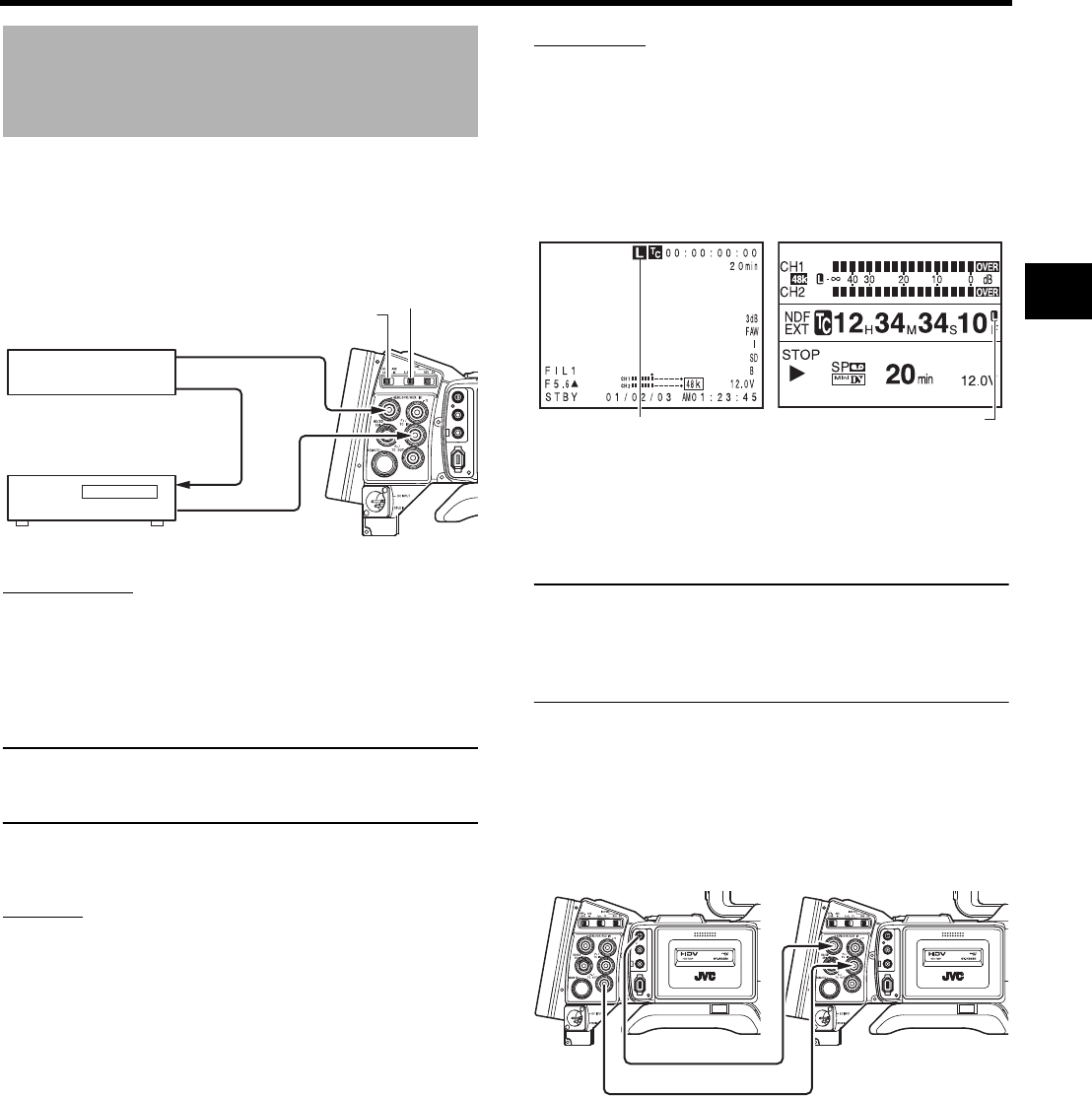
49
Synchronizing with an Exter-
nal Time Code Generator
Synchronize the built-in time code generator with the
SMPTE/EBU-compliant LTC time code, which is input from
the [TC IN] terminal. After synchronization (slave lock), the
built-in time code generator continues to run even if external
time code are not input.
Connection
Input external synchronization signal to the external time
code generator and the GENLOCK/AUX IN terminal of this
device.
Use BB signals or Tri-sync HD signals as the external syn-
chronization signals.
CAUTION
When the power switch is turned on while the external syn-
chronization signal is input, a vertical vibration occurs for a
few seconds. This is not a malfunction.
Input SMPTE/EBU-compliant LTC time code signal to the
PB/TC IN terminal.
Setting
Set the [GENLOCK/AUX IN] switch to GENLOCK.
Set the [PBPR/TC] switch to TC.
Set TCG SOURCE in the TC/UB/CLOCK menu screen to
EXTERNAL.
Set the LCD screen or viewfinder to STATUS 1 screen dis-
play.
Or set the LCD screen to enlarged status display screen.
XSee page 29.
Operation
1. Set the external time code generator and operate it.
• The built-in time code generator synchronizes with the
input external time code data.
“L” lights up in the STATUS 1 screen of LCD screen or
viewfinder. ”L” also lights up when the LCD screen is in
enlarged character display.
• “L” blinks when the time code cannot be synchronized.
2. The built-in time code generator continues to run even if
the external time code generator is disconnected after
synchronization.
CAUTION
• If a time code generator is connected or disconnected
during recording, servo lock will be disturbed.
• The user's bit data range for an input external time code
generator is 00 00 00 00 to FF FF FF FE.
When FF FF FF FF is entered, FF FF FF FE is recorded.
When connecting multiple devices and assigning one
as the master unit and others as slave units
If there is only one slave unit, connect as shown below.
If there are multiple slave units, input external synchroniza-
tion signals to all GENLOCK/AUX IN terminals from the syn-
chronization signal generator.
IEEE 1394
CH2-AUDIO OUT-CH1 VIDEO
Synchronization signal
generator
Synchronization signal
LTC time code
External time code
generator
Synchronization signal
TC IN
GENLOCK
IN
GENLOCK/AUX IN switch
PBPR/TC switch
STATUS 1 screen
Lights up
Enlarged display screen
Lights up
IEEE 1394
CH2-AUDIO OUT-CH1 VIDEO
IEEE 1394
CH2-AUDIO OUT-CH1 VIDEO
Master unit
VIDEO OUT
Slave unit
TC IN
TC OUT
GENLOCK IN
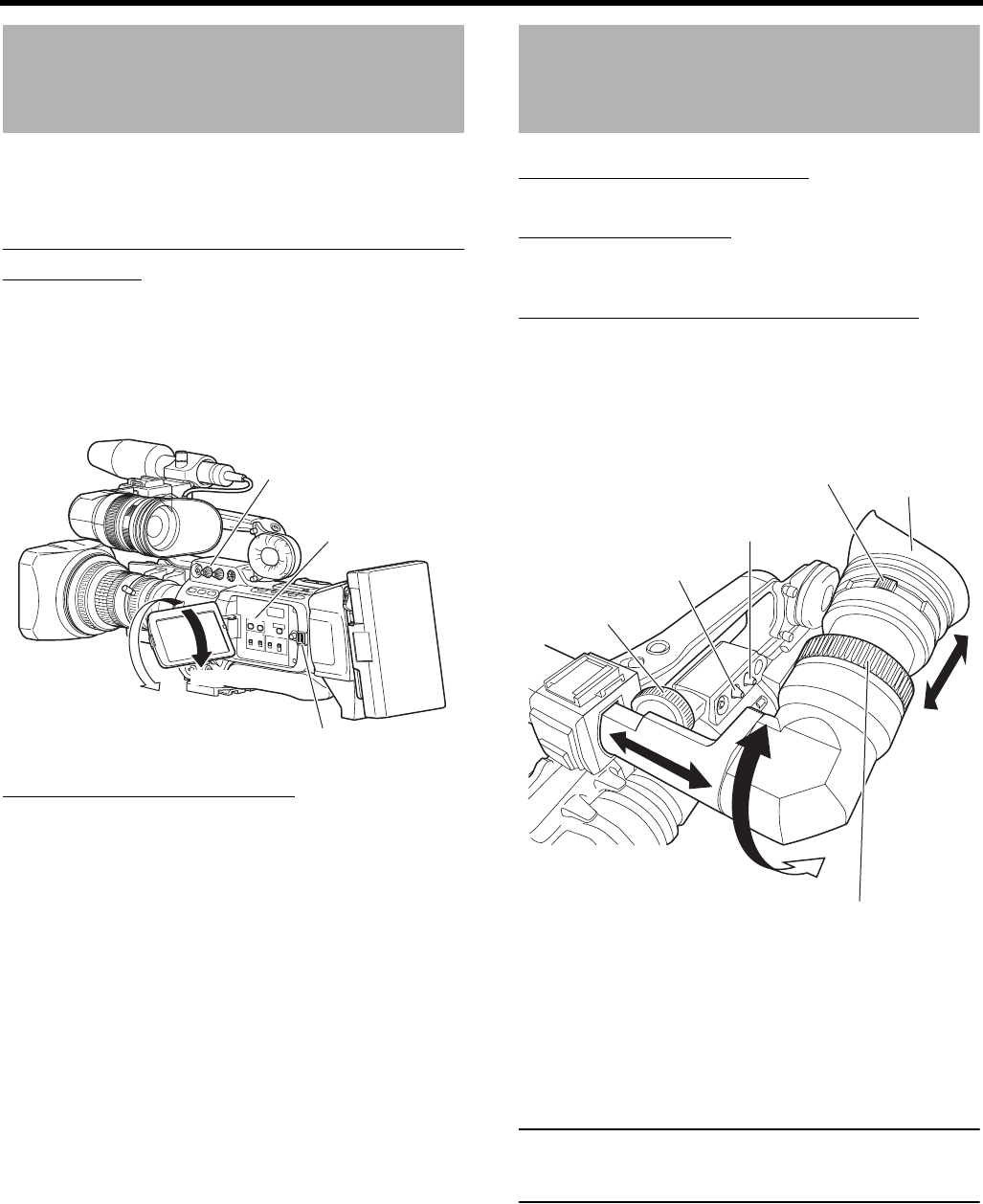
PREPARATIONS FOR OPERATION
50
Screen Adjustment
LCD monitor direction, angle, screen brightness, etc. can be
adjusted.
Adjusting the Direction and Angle of the
LCD monitor
• With the LCD door in the open condition, rotate the LCD
door.
• It can be turned 180° in upward direction and 90° in down-
ward direction.
When turned 180° upward direction, the LCD monitor can
be viewed from the lens side (vertically inverted image).
Adjusting the LCD monitor
• PEAKING:
Adjusts the contour of the LCD monitor.
• LCD BRIGHT:
Adjusts the brightness of the LCD monitor.
Adjustments are made on the LCD/VF[2/4] menu screen.
XSee page 90.
• LCD MIRROR MODE:
Sets the LCD monitor to display mirrored images when
shooting facing the subject.
Adjustments are made on the LCD/VF[4/4] menu screen.
XSee page 92.
• LCD CONTRAST:
Adjusts the contrast of the LCD monitor.
• BLACK & WHITE:
Sets the LCD monitor and viewfinder to black and white
display.
Viewfinder Adjustment
Direction of the Viewfinder
Adjust the position and angle of the viewfinder.
Diopter Adjustment
Rotate the eyepiece focusing ring until the viewfinder screen
image is clearly visible.
Adjustment of the Viewfinder Screen
• PEAKING:
Adjusts the contour of the LCD monitor and the viewfinder
screen.
•VF BRIGHT:
Adjusts the brightness of the viewfinder screen.
Adjustments are made on the LCD/VF[4/4] menu screen.
XSee page 92.
• VF CONTRAST:
Adjusts the contrast of the viewfinder screen.
•BLACK & WHITE:
Sets the LCD monitor and viewfinder to black and white
display.
MEMO
The screen size of the viewfinder can be changed by
selecting the desired size with the ASPECT item on the
VIDEO FORMAT[1/2] menu screen (4:3 or 16:9).
CH-2
CH-1
-
+
AUDIO SELECT
MANU
AUTO
TC
LCD BRIGHT
DISPLAY
TC
UB
FREE
REGEN
GENE.
REC
CAM/VTR
PEAKING volume
LCD BRIGHT
button
LCD lock release lever
180° up 90° down
Eyepiece focusing ring
VF BRIGHT volume
Eyepiece
PEAKING volume
Sliding securing ring
Viewfinder mount base
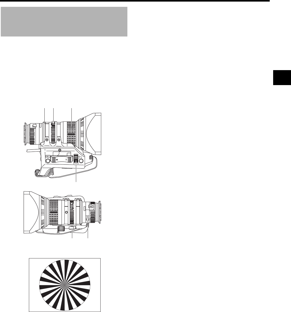
51
Back Focus Adjustment
It is only necessary to perform this when the lens is attached
for the first time or when focusing is not correct in both the
telephoto and wide-angle positions.
• It is easier to adjust back focus when the subject is more
than 3 meters from the camera.
The optimal subject for this adjustment is a Siemens star
chart.
1. Set the IRIS mode switch to M (Manual).
2. Set the zoom mode to M (Manual).
3. Open the iris by turning the iris ring.
If the illumination is too strong, reduce it or move to a
darker place.
4. Turn the zoom lever until the lens is at the maximum tele-
photo position.
5. Bring the subject into focus.
6. Set the lens to maximum wide-angle.
7. Loosen the back focus ring retaining knob.
8. View the same subject and adjust the back focus ring for
the best possible focus.
9. Repeat steps 4. through 8. about three times for fine
adjustment until the subject remains in focus in both the
telephoto position and the wide-angle position.
10.Tighten the back focus ring retaining knob to secure the
ring.
Siemens star chart
34, 6 5
1
2 7, 8, 10
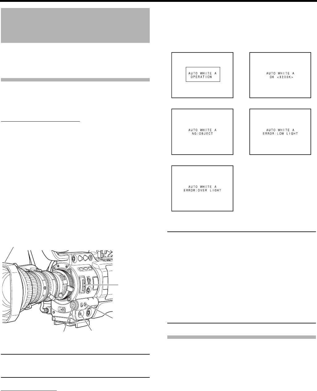
PREPARATIONS FOR OPERATION
52
White Balance Adjustment
Since the color of light (color temperature) varies depending on
the light source, it is necessary to re-adjust the white balance
when the main light source illuminating the subject changes.
White Balance Adjustment
Two kinds of white balance adjustment results can be stored
in memories AUTO A and AUTO B.
Adjustment procedure
1. Set the following switches.
• Set the POWER switch to ON.
• Set the IRIS mode switch of the lens to A (Auto).
• Set the FULL AUTO switch to OFF.
2. Set the ND filter switch according to the current lighting.
3. Set the WHT.BAL switch to A or B.
4. Place a white object near the center of the screen under
the same lighting conditions as the target subject and
zoom in to fill the screen with white.
5. Press the AWB (Auto White Balance) button.
“AUTO WHITE A, B OPERATION” is displayed in the view-
finder while the auto white balance adjustment circuit operates.
When correct white balance is obtained, the approximate
color temperature is displayed together with “AUTO
WHITE A, B OK” for about 5 seconds.
MEMO
Fine-tune red and blue to match the white adjusted in white
balance in WHITE PAINT<R>/<B> on the WHITE BAL-
ANCE menu screen. XSee page 85.
Error messages
If the adjustment ends abnormally, an error message, as
described below, blinks for about 5 seconds.
• NG: OBJECT (Improper object)
Displayed when there is not enough white color on an
object or the color temperature is not suitable.
Replace the color temperature conversion filter or use
another white object and re-adjust the white balance.
• ERROR: LOW LIGHT (Insufficient illumination)
Displayed when the illumination is dim. Increase the illumi-
nation and then re-adjust the white balance.
• ERROR: OVER LIGHT (Excessive illumination)
Displayed when the light is excessively bright. Decrease
the illumination and then re-adjust the white balance.
CAUTION
• Do not adjust using any highly reflective objects, such as
metal, etc., as this may result in improper white balance
adjustment.
• The FAW (Full Auto White balance) function cannot pro-
vide optimum white balance with a subject outside the
FAW adjustment range, for example when it contains
only a single color or not enough white color.
• The accuracy of the FAW (Full Auto White balance) is
inferior to that of the Auto white balance.
• When the power is turned on with the FAW mode
selected, it takes about 10 seconds for the FAW adjust-
ment to be completed.
Do not shoot within this interval.
Full Auto White Balance (FAW)
The FAW function adjusts the white balance value automati-
cally as the lighting condition changes.
This mode is convenient when you have no time to adjust the
white balance or when the camera is moved frequently in
and out of places under different lighting conditions.
Setting procedure
The FAW function can be activated with the FAW item on
the SWITCH MODE menu screen. The FAW function can
be allocated to one of the white balance switching
switches A, B, or PRESET.
XSee page 86.
Iris mode switch (7 on page 10)
ND filter
WHT.BAL
switch
POWER switch
AWB button
During operation Result message
Improper object Insufficient illumination
Excessive illumination
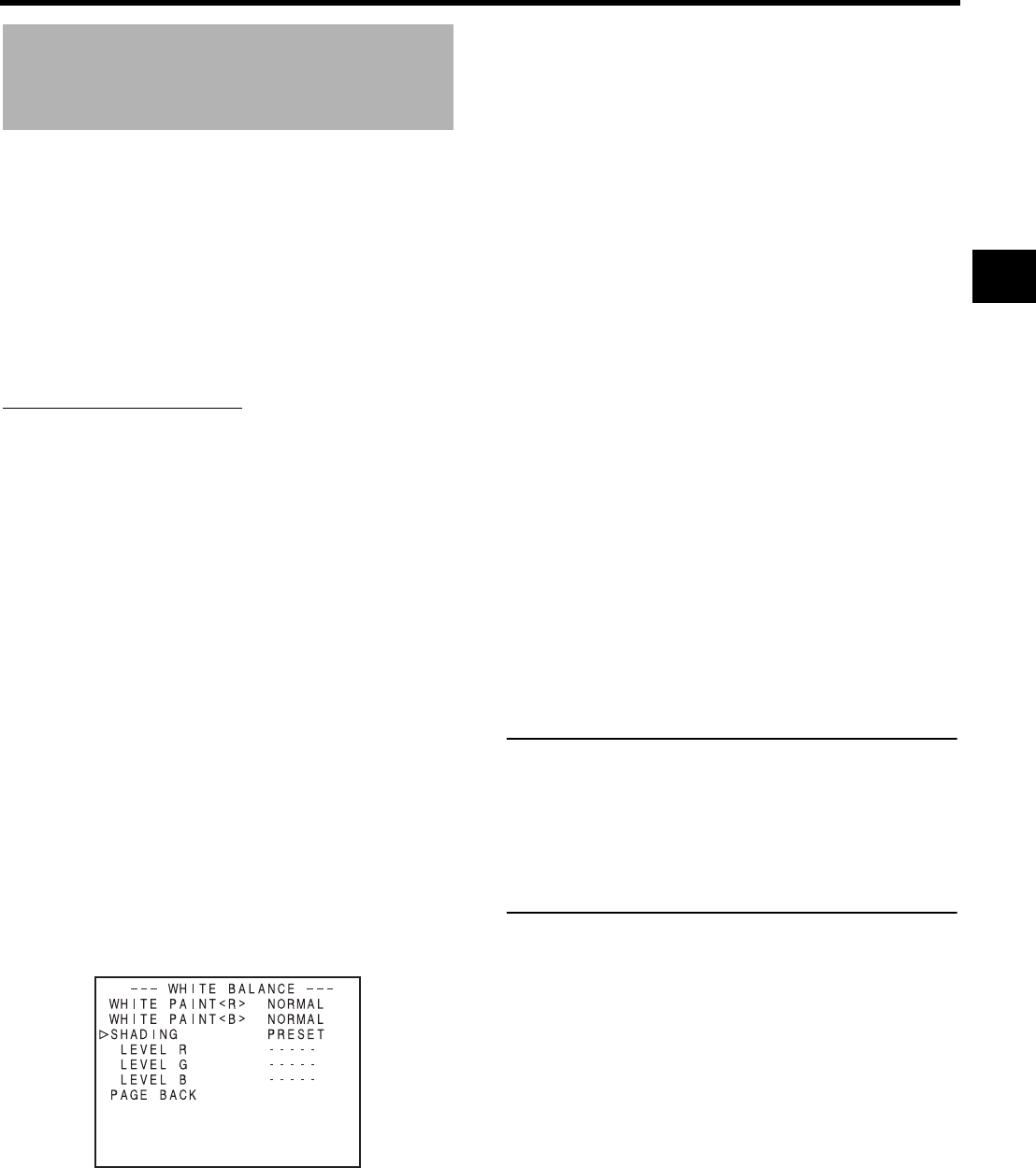
53
White Shading Adjustment
It is necessary to perform this adjustment to the camera
when attaching a lens that is different from the previously
attached lens.
Even if white balance is achieved in the middle of the screen,
it may not be achieved at the top and bottom of the screen.
Greens and magentas may be colored. This is due to char-
acteristics of the lens. Correcting this phenomenon is called
White Shading Adjustment.
Perform this after adjusting white balance.
White shading adjustment is performed on the WHITE BAL-
ANCE menu screen.
Adjustment procedure
1. White balance the camera.
2. Set the camera's lens controls as follows:
a. Set the IRIS opening to F4 or higher number.
b. In the case of a zoom lens set the ZOOM at the center
of its range.
3. Shoot a uniformly lit white sheet of paper and fill the mon-
itor screen with it.
4. Set the monitor CHROMA level to maximum.
5. Check the color of the monitor screen. If the top and the
bottom of the monitor screen are white then no adjust-
ment is necessary. If the top of the monitor screen is
greenish and the bottom is reddish or if the top is reddish
and the bottom is greenish then continue with this adjust-
ment.
6. Adjust the LEVEL G in the SHADING menu item to mini-
mize the color difference between the top and bottom of
the screen.
7. It is recommended that only LEVEL G be adjusted.
1Display the WHITE BALANCE menu screen.
Follow the steps in “Setting Menu Screens” on page 75
and proceed as follows.
MENUrCAMERA PROCESS[1/2]rCAMERA PRO-
CESS[2/2]rADVANCE PROCESSrWHITE BALANCE
Setting in the WHITE BALANCE screen is performed as fol-
lows.
Selecting an item
Turn the SHUTTER dial to align the cursor (j) with the
desired item, and press the SHUTTER dial.
• The item is selected and the setting value blinks.
Changing the setting value
Turn the SHUTTER dial to change the blinking value. When
the SHUTTER dial is pressed, the value stops blinking and
the setting is changed.
2Perform the above steps to set SHADING to MANUAL.
3Select LEVEL R, LEVEL G, LEVEL B and press the
SHUTTER dial.
• The setting value for the selected LEVEL blinks and
becomes available for changing.
4Change the setting values for LEVEL R, LEVEL G, and
LEVEL B with the SHUTTER dial while referring to the
monitor.
When setting values are increased, colors at the bottom
of the screen are suppressed and the top is enhanced.
LEVEL R: Adjusts reds.
LEVEL G: Adjusts greens.
LEVEL B: Adjusts blues.
<Range: -128 to +127>
5Press the SHUTTER dial after changing the setting val-
ues to save in the memory.
6Press the STATUS button to return to the normal screen.
8. When white shading adjustment is completed, adjust
white balance again.
XSee “White Balance Adjustment” on page 52.
CAUTION
• If the lens setup is incorrect, the white shading adjust-
ment might result in over compensation. When perform-
ing this adjustment, set the lens to the recommended
settings. Do not open the lens IRIS beyond F4; do not
set a telephoto lens to its extreme wide position or tele-
photo position.
• White shading occurs due to the optical characteristics of
the mounted lens, it is not a camera malfunction.
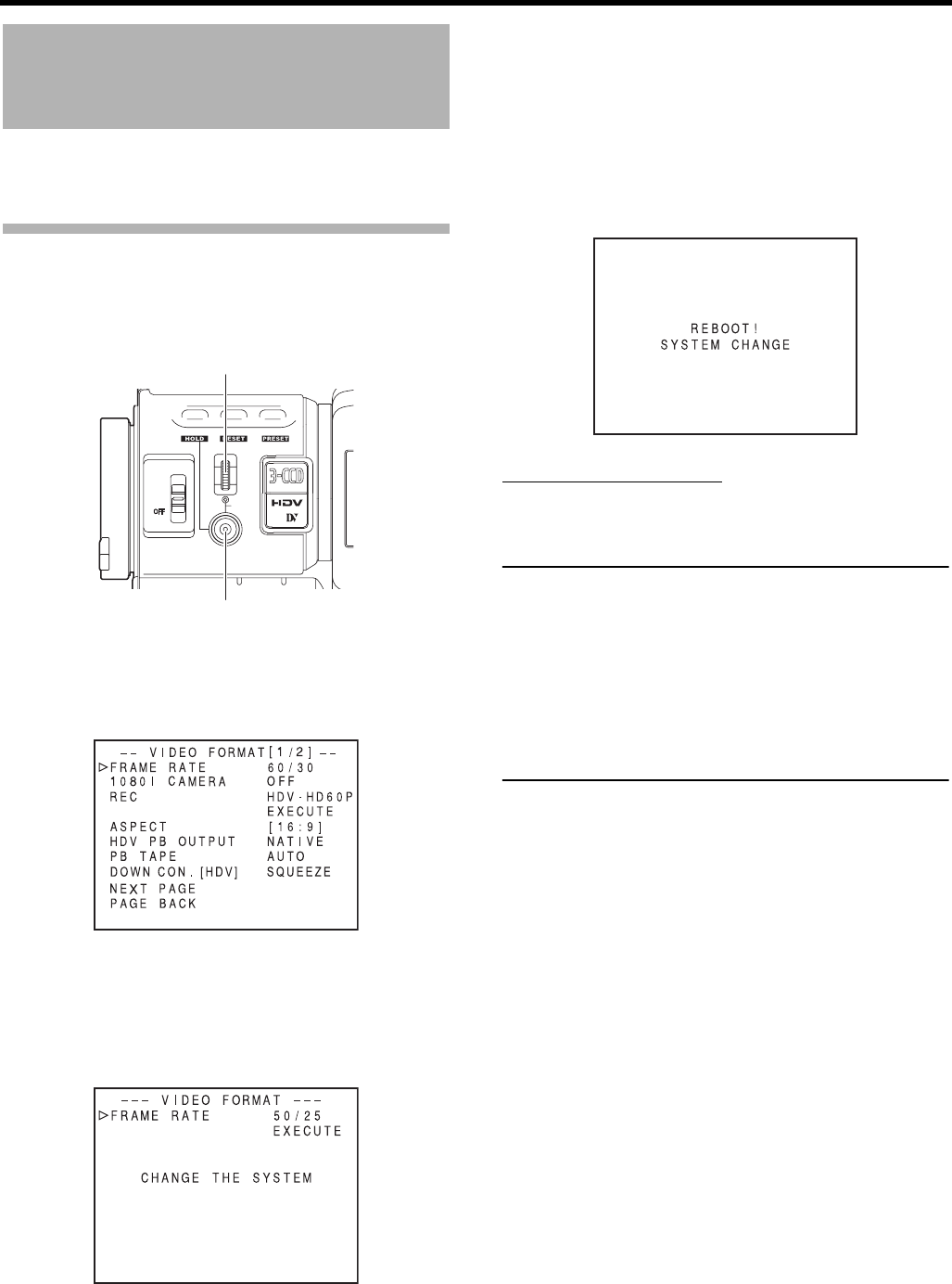
54
SETTING AND ADJUSTMENTS BEFORE SHOOTING
Setting the Video Format
Set the video format using the FRAME RATE item and the
REC item on the VIDEO FORMAT menu screen.
Setting the FRAME RATE Item
1. Press the STATUS button for at least 1 second.
• The TOP MENU screen is displayed.
2. Turn the SHUTTER dial and bring the cursor (K) to the
VIDEO FORMAT.. item and press the SHUTTER dial.
• The VIDEO FORMAT[1/2] menu screen is displayed.
3. Turn the SHUTTER dial and bring the cursor (K) to the
FRAME RATE item and press the SHUTTER dial.
• The setting for the selected item flashes and can be
changed.
“CHANGE THE SYSTEM” is displayed on the screen.
4. Turn the SHUTTER dial, change the setting and push the
SHUTTER dial.
• The setting stops flashing and is temporarily set.
• Move the cursor (K) to the EXECUTE item and EXE-
CUTE flashes.
5. Push the SHUTTER dial.
• “REBOOT! SYSTEM CHANGE” is displayed on the
screen and after a few seconds the system is reboo-
ted.
Setting the REC Item
Set the REC item using the same steps as for the FRAME
RATE item.
MEMO
• If you change the FRAME RATE item setting, the system
is rebooted.
• The synchronous video signal is momentarily disturbed
when the REC item setting is switched.
• We recommend the following settings for REC item (in
HDV format).
When recording images with a lot of motion:
Set to HDV60p or HDV50p
When recording images with little motion:
Set to HDV30p or HDV25p
USER 3USER 2USER 1
STATUS
MENU
2
1
ND FILTER
SHUTTER
SHUTTER dial
STATUS button
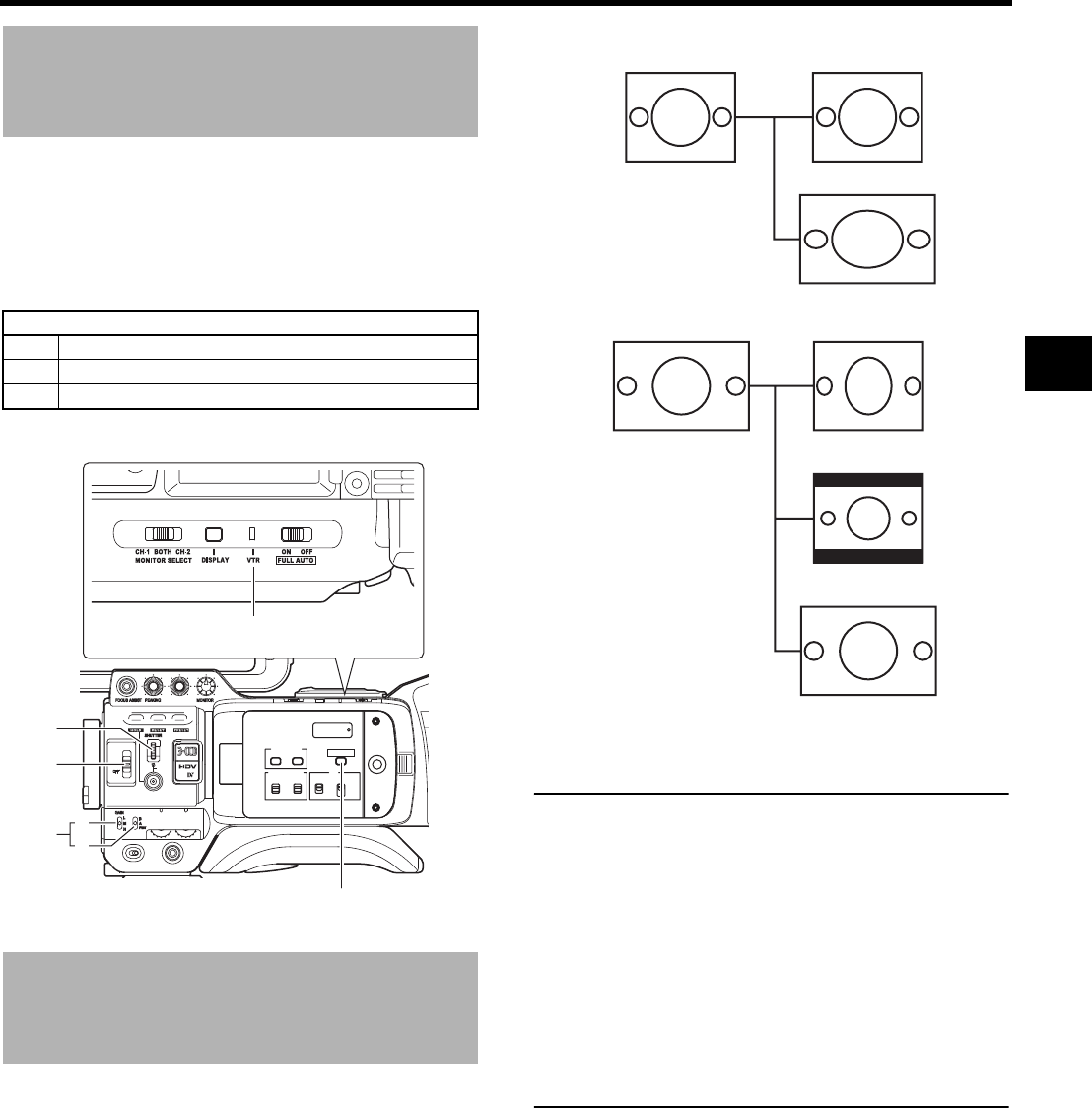
55
Camera Settings
1. Set the switch positions.
A. [GAIN] switch: Set to L ( 0 dB).
B. [WHT. BAL] (Auto White Balance) switch: Set to A or
B.
2. Set the lens’ iris mode switch to “A” (Auto iris side).
3. Select the ND filter.
4. Set the shutter speed to OFF with the SHUTTER dial.
Screen Size (4:3/16:9)
Mode Selection
The screen size of recorded images can be selected with the
ASPECT item on the VIDEO FORMAT[1/2] menu screen.
XSee page 78.
• To record using the standard screen, set ASPECT to 4:3.
• To record using the 16:9 screen, set ASPECT to 16:9.
• In DV mode, selection of SQUEEZE and LETTER is not
possible. The screen display mode becomes SQUEEZE.
MEMO
• When you set the REC item on the VIDEO FORMAT[1/2]
menu to HDV format, the ASPECT item is fixed at 16:9
and “[16:9]” is displayed.
• If the above applies, you can set to display the image in
the style of 4:3 televisions.
XSee “DOWN CON. [HDV]” on page 78.
• In the SAFETY ZONE item on the LCD/VF[1/4] menu
screen, you can display the safety zone for a standard
screen as well as a 16:9 screen in the viewfinder or LCD
monitor.
XSee page 89.
• When the ASPECT item is set to 4:3, the screen that is
displayed may differ depending on the 16:9 television
you are using.
ND FILTER Suitable Location
OFF OFF Indoors, dark outdoors
1 1/4ND Outdoors under clear sky
2 1/16ND Outdoors under extremely clear sky
USER 3USER 2USER 1
STATUS
MENU
2
1
ND FILTER
REC
OFF
ON
POWER
WHT.BAL
AUTO
AUDIO
LEVEL
AUTO
CH-1 CH-2
VF BRIGHT
CH-2
CH-1
-
+
AUDIO SELECT
MANU
AUTO
TC
LCD BRIGHT
DISPLAY
TC
UB
FREE
REGEN
GENE.
REC
CAM/VTR
A
B
CAM/VTR button
VTR indicator
4.
3.
1.
ASPECT item
4:3 4:3 TV
16:9 TV
4:3 TV16:9
4:3 TV
16:9 TV
[LETTER]
[SQUEEZE]
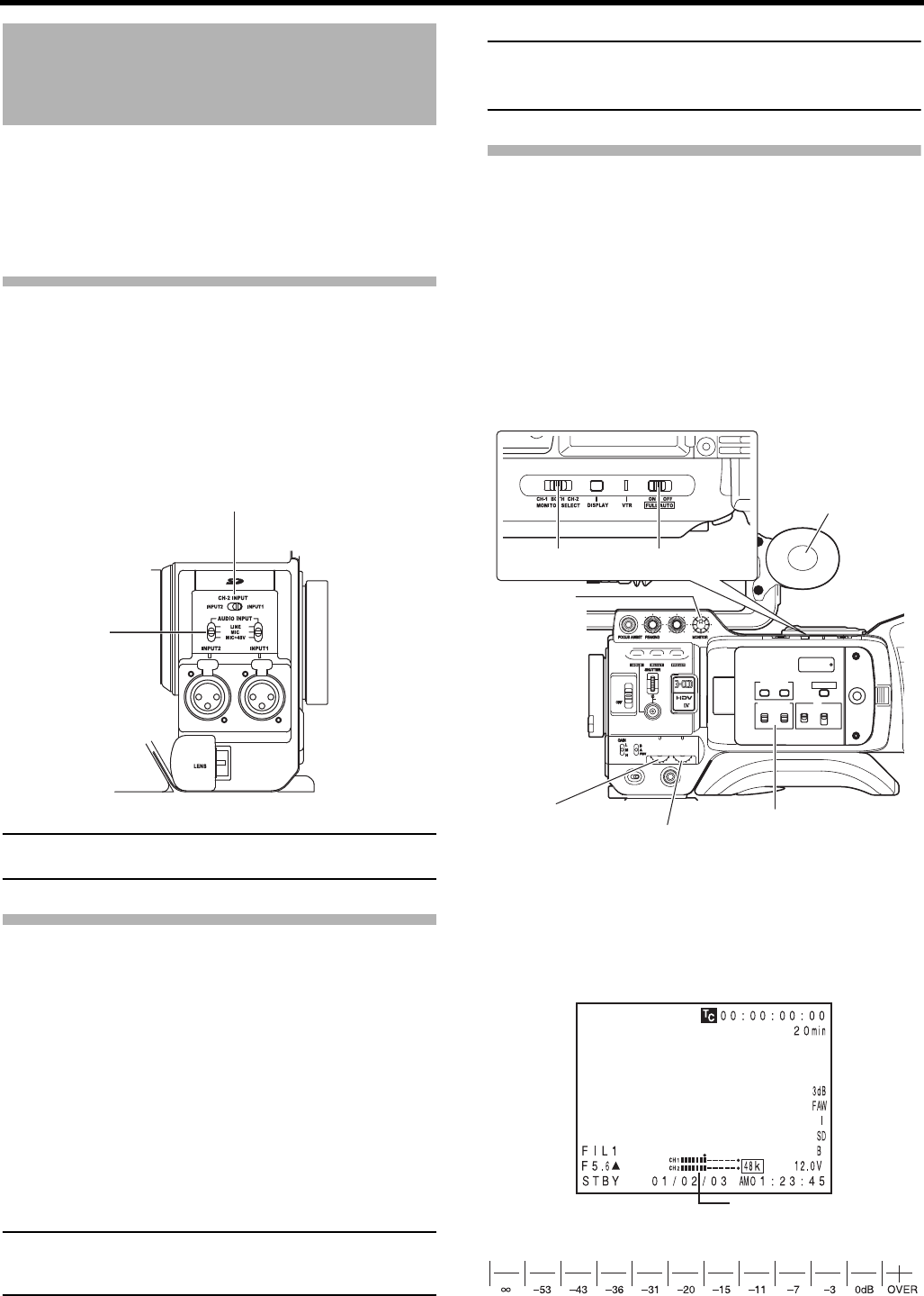
SETTING AND ADJUSTMENTS BEFORE SHOOTING
56
Audio Input Signal Selec-
tion
The GY-HD250/GY-HD251 is provided with the INPUT1 con-
nector and the INPUT2 connector for audio input.
Select the audio from the INPUT1 connector or the INPUT2
connector using the CH-2 INPUT switch for the audio to be
recorded in CH-2.
Selecting the CH-2 channel input
connector
Select using the CH-2 INPUT switch.
MEMO
The audio from the INPUT1 connector is also input into CH-
1 regardless of the setting.
Selecting the audio signal input
Select the sound to be input to the INPUT1 or INPUT2 con-
nector using the AUDIO INPUT switch.
The setting is made for each of INPUT1 or INPUT2 connector.
CAUTION
When connecting a component that does not require +48 V
power supply, make sure that the switch is not set to
MIC+48V before the component is connected.
MEMO
You can select the normal input level for MIC and MIC+48V
in the INPUT1, 2 MIC REF. item on the AUDIO/MIC[1/2]
menu screen.
Adjusting Audio during Recording
For each audio channel, use the CH-1/CH-2 AUDIO
SELECT switch to select whether the audio level adjustment
should be set to AUTO mode or MANUAL mode.
Adjusting the audio input level control
The audio input level can be adjusted manually when the GY-
HD250/GY-HD251 is in the record, record-standby or stop mode.
1. Set the CH-1/CH-2 AUDIO SELECT switch of the chan-
nel whose audio level that you want to adjust manually to
MANU.
2. Rotate the audio input level control corresponding to the
audio input level to be adjusted.
• Adjust so that the peak level does not exceed the –3 dB
point when a loud sound is input.
INPUT1 : Inputs the audio from the INPUT1 connector
into CH-2.
INPUT2 : Inputs the audio from the INPUT2 connector
into CH-2.
LINE : Set to this position when connected to audio
equipment, etc.
The reference input level is +4 dBs.
MIC : Set to this position when using a dynamic
microphone.
MIC+48V : Set to this position when a microphone (phan-
tom microphone) requiring +48 V DC power
supply is connected.
CH-2 INPUT switch
AUDIO INPUT
switch
USER 3USER 2USER 1
STATUS
MENU
2
1
ND FILTER
REC
OFF
ON
POWER
WHT.BAL
AUTO
AUDIO
LEVEL
AUTO
CH-1 CH-2
VF BRIGHT
CH-2
CH-1
-
+
AUDIO SELECT
MANU
AUTO
TC
LCD BRIGHT
DISPLAY
TC
UB
FREE
REGEN
GENE.
REC
CAM/VTR
MONITOR SELECT
switch
FULL AUTO switch
Monitor
speaker
MONITOR
volume
CH-1 audio input
level volume CH-2 audio input level
volume
CH-1/CH-2
AUDIO SELECT switch
STATUS 1 screen
Audio level
Indicator level (reference)
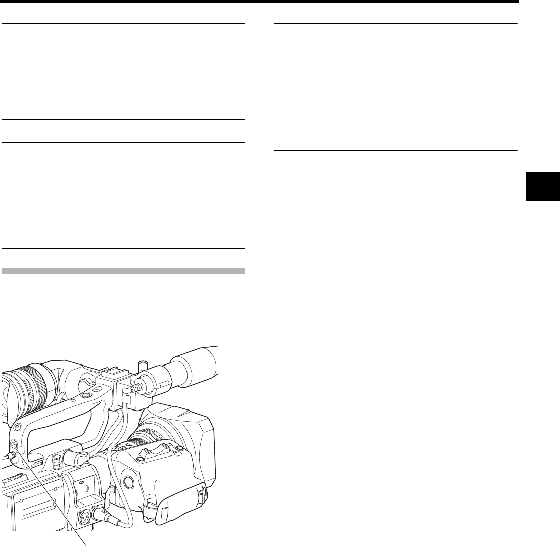
57
MEMO
• When AUDIO LIMITER in the AUDIO/MIC[1/2] menu
screen is set to ON, the AUDIO LIMITER functions in
manual adjust mode. Recording level is suppressed
when excessive audio is input.
XSee “AUDIO LIMITER” on page 87.
• The reference level for audio recorded on the tape can
be set with the AUDIO REF. LEVEL item on the AUDIO/
MIC menu screen. (–20 dB or –12 dB) The level will
change for both CH-1 and CH-2.
CAUTION
• When the AUDIO INPUT switch is set to MIC, be sure to
check that the microphone is connected to the INPUT1/2
connector. If the microphone is not connected, increasing the
audio level could cause noise from the input connector to be
recorded on the tape. When the microphone is not con-
nected to the INPUT1/2 connector, set the AUDIO INPUT
switch to “LINE” or turn down the audio level control.
• In the FULL AUTO mode, the audio level volume cannot
be adjusted with the audio level controls on the CH-1 and
CH-2.
Monitoring Audio during Recording
The audio input during recording, in record-pause or stop
mode can be monitored through the monitoring speaker or
earphone.
• Select the audio channel to be monitored using the MONI-
TOR SELECT switch.
• The MONITOR volume control adjusts the monitoring vol-
ume.
• The loudspeaker or earphone outputs an alarm tone in the
case of an abnormal condition occurring in this device.
An alarm tone is also output when the tape end is reached
or when the battery is running down.
* Do not increase the audio monitoring volume exces-
sively; otherwise howling with the camera microphone
may occur.
MEMO
• When connecting a stereotype earphone, make the fol-
lowing settings to output stereo sound.
1Set the MONITOR SELECT switch to BOTH.
2
Set the AUDIO MONITOR item on the AUDIO/MIC[2/2]
menu screen to STEREO.
• When AUDIO MONITOR item on the AUDIO/MIC[2/2]
menu screen is set to “STEREO”, only the audio of CH-1
is output from the monitoring speaker.
• The volume of the alarm tone is set with the ALARM VR
LEVEL item on the OTHERS[1/2] menu screen. (OFF/
LOW/MIDDLE/HIGH)
CH-1 : The sound input to the CH-1 channel is output.
BOTH : The sound input to the CH-1 and CH-2 chan-
nels is output mixed.
CH-2 : The sound input to the CH-2 channel is output.
PHONES jack
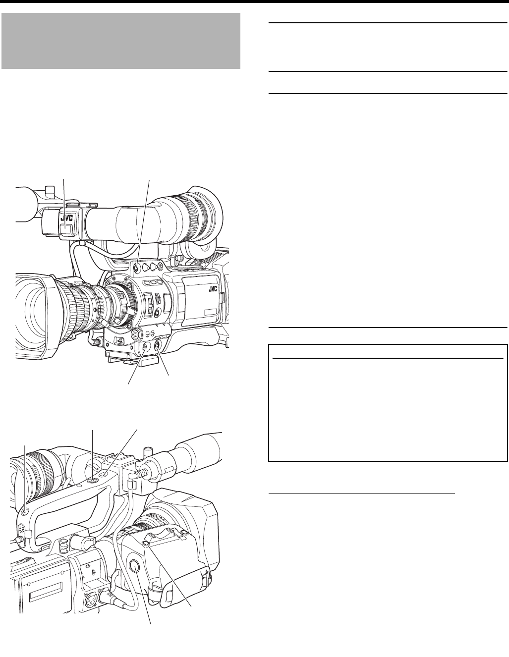
58
SHOOTING OPERATION
Basic Recording Opera-
tion
1. Set the POWER switch to ON.
• This device turns on in camera mode.
2. Start recording.
Press the REC/VTR trigger button on the GY-HD250/GY-
HD251 to start recording.
Once recording has started, the FRONT TALLY lamp and
BACK TALLY lamp light red.
MEMO
The way the FRONT TALLY and the BACK TALLY lamps
flash differ depending on what you set in the FRONT
TALLY and BACK TALLY items on the OTHERS[1/2] menu
screen. XSee page 96.
CAUTION
• This device enters the stop mode automatically at TAPE
END. If this mode continues for 3 minutes, the mode
switches to the tape protect mode.
X
See “OTHERS[1/2] Menu Screen” on page 96.
(LONG PAUSE TIME item)
• If the REC/VTR trigger button is pressed very quickly
and repeatedly, or the POWER switch is moved immedi-
ately after the trigger button is pressed, the GY-HD250/
GY-HD251 may not enter the record mode.
To remedy this condition set the POWER switch to OFF
and wait for 5 seconds or more before turning the power
on again.
• A neat transition to the next recorded scene cannot be
guaranteed if a recording is ended by turning the
POWER switch or DC power supply OFF, or by removing
the battery pack.
• Trial-shooting is always recommended before recording
important events to confirm the recording is satisfactory.
• The microphone may pick up the sound of the lens’ iris if
the iris is changed abruptly or the iris is manually moved
abruptly during recording.
About the Focus Assist Function
When you press this button during shooting, the area of
focus is displayed in blue, red or green, making it easy to
focus accurately.
XSee “LCD/VF[1/4] Menu Screen” on page 89.
You can also set this function from the RET button.
XSee “SWITCH MODE Menu Screen” on page 86. (LENS
RET item)
When FOCUS ASSIST on the LCD/VF[1/4] menu screen is
set to ACCU-FOCUS, ACCU FOCUS functions with FOCUS
ASSIST. This makes focusing with shallower depth of field
easier. ACCU FOCUS automatically turns OFF after approxi-
mately 10 seconds. XSee page 89
FRONT TALLY lamp
POWER switch
FOCUS ASSIST button
REC trigger button
REC trigger button
BACK TALLY lamp
RET button
VTR trigger button
FOCUS ASSIST
button
About the QUICK REC START Mode
If the REC/VTR trigger button is pressed immediately after
the videocassette is inserted, the mode becomes the
QUICK REC START mode that enables quick start of
recording.
However, when shooting starts in the middle of the tape, a
blank space appears as the new scene will not be linked
smoothly with the previous image.
Also, the time code does not continue. (Some overlap may
also occur.)

59
If the Record-Standby Mode Contin-
ues
Setting the time before the tape protection mode is engaged
The time before the tape protection mode is engaged from
the record-standby mode can be set to 5 minutes or 3 min-
utes with the LONG PAUSE TIME item on the OTHERS[1/2]
screen menu. XSeepage96.
When the record-standby mode has continued for about 5
minutes or 3 minutes, the GY-HD250/GY-HD251 automati-
cally stops drum rotation in order to protect the tape. (Tape
protect mode)
In the tape protect mode, STOP is shown as the VTR
mode indication on the LCD monitor and in the viewfinder
screen. (STATUS 1 screen)
To start recording from the tape protect mode, press the
REC/VTR trigger button.
• The drum starts rotating, and recording starts after
about 3 seconds.
To return to the record-standby mode from the tape protect
mode, press the RET button.
CAUTION
This function does not work when using RET button is used
as FOCUS ASSIST button.
Checking Recorded Contents in
Record-Standby Mode (Recording
Check Function)
This function is available only when the GY-HD250/GY-
HD251 is in the standby mode.
In standby mode, about 5 seconds of the last part of the con-
tent recorded in DV format can be played back, and about 7
seconds when the content was recorded in HDV format can
be played back.
• The recorded contents can be checked on the LCD moni-
tor, in the viewfinder or on a monitor connected to the
video signal output connectors.
1. In the record-standby mode, press the RET button on the
camera lens section.
• The tape rewinds and about 6 seconds of the content
recorded in DV format is played back, and about 8 sec-
onds of the content recorded in HDV format is played
back. After playback, this device returns to standby
mode at the position on the tape where the RET button
was pressed.
If you continue to hold down the RET button, up to about
18 seconds of content recorded in DV format and up to
about 20 seconds of content recorded in HDV format can
be rewound and played back.
• Pressing the REC/VTR trigger button during playback
will put this device in REC standby mode. The camera
will automatically return to recording mode after play-
back.
CAUTION
• This function does not work when using RET button is
used as FOCUS ASSIST button.
• This function does not work when the GY-HD250/GY-
HD251 is in the stop mode.
• During recording check, the following indication will
appear if the error rate increases due to head clogging,
etc.
“HEAD CLEANING REQUIRED!” is shown on the LCD
monitor or in the viewfinder. (When the STATUS 0, 1, 4
screen is displayed.)
VTR mode indication
1. RET button
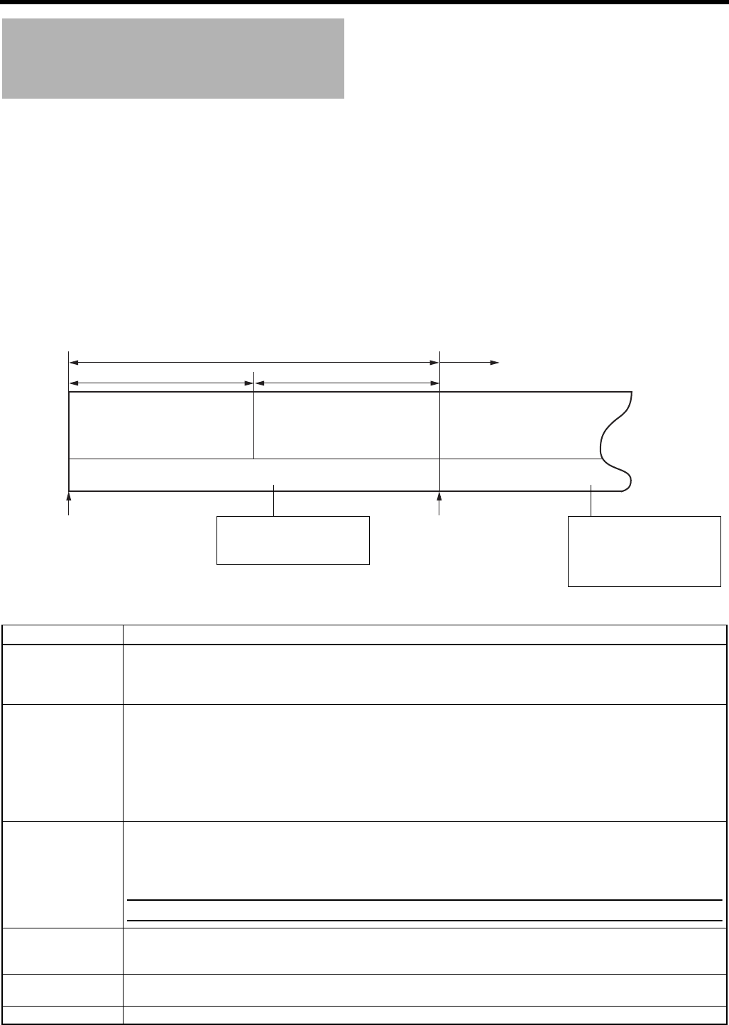
SHOOTING OPERATION
60
HEADER REC Function
When the REC/VTR trigger button is pressed while the STOP button is pressed, this function first records the color bar video and
the test tone (1 kHz sine-wave) of the built-in signal generator at the beginning of the tape. Then it records the black video signal
and the mute audio signal for the duration specified in advance. When the recording is completed, this device enters the Record-
Standby mode. The time code value at the Record-Standby position becomes the time code specified in advance. (HEADER
REC function)
• Settings related to the HEADER REC function, such as whether the HEADER REC function should be enabled, the HEADER
REC execution duration, and the time code value setting when the HEADER REC recording is completed, etc., are made on
the HEADER REC menu screen.
• The HEADER REC function is enabled when TCG SOURCE on the TC/UB/CLOCK menu screen is set to INTERNAL.
• The HEADER REC function is executed under the following circumstances:
CAM/VTR button: Set to CAM mode.
In the Record-Standby or Stop mode
HEADER REC menu screen contents
Item Function/Initial Setting
START KEY Sets whether the HEADER REC operation should be executed when the REC/VTR trigger button is pressed while the
STOP button is pressed.
DISABLE : HEADER REC operation is not executed.
STOP+REC : HEADER REC operation is executed.
TC DATA Sets the time code value for the point when the Record-Standby mode is engaged following completion of HEADER
REC.
EXECUTE : Confirms the set time code.
ZERO PRESET: Resets all time codes to zero “0”.
CANCEL : Clears the set time code.
The frame mode is set depending on the setting in the DROP FRAME item on the TC/UB/CLOCK menu screen.
* The time code value at the point when the Record-Standby mode is engaged may differ some frames from the value
set for this item.
UB DATA Sets the user’s bits of the HEADER REC section.
EXECUTE : Confirms the set user’s bits.
ZERO PRESET: Resets all user’s bits data to zero “0”.
CANCEL : Clears the set user’s bits.
MEMO
The user’s bits for the normal recording section are set on the TC/UB/CLOCK menu screen.
BARS TIME Sets the duration (seconds) in which the color bar signal and test tone (1 kHz) is recorded during HEADER REC. (1-sec
steps)
[Initial Setting: 0SEC - 30SEC - 99SEC]
BLACK TIME Sets the duration (seconds) in which the black signal is recorded during HEADER REC. (1-sec steps)
[Initial Setting: 0SEC - 30SEC - 99SEC]
PAGE BACK The TC/UB/CLOCK menu screen returns when the SHUTTER dial is pressed.
Tape beginning HEADER REC Record-Standby mode
Normal recording
(Example) 30 sec (Example) 30 sec
Color bar video signal
Test tone (1 kHz)
(Setting range: 0 to 99 sec)
Black video signal
Mute audio (No sound)
(Setting range: 0 to 99 sec)
Time code, user’s bits recording Time code, user’s bits recording
Time code:
The value specified on the HEADER
REC menu screen- HEADER REC time.
(Example) 23:59:00:00
Time code:
The value specified on the HEADER
REC menu screen.
(Example) 00:00:00:00
User’s bits:
The value specified for the UB
DATA item on the HEADER REC
menu screen.
User’s bits:
The value specified for the UB
PRESET item on the TC/UB/
CLOCK menu screen.
(only when set to REC RUN or
FREE RUN mode)
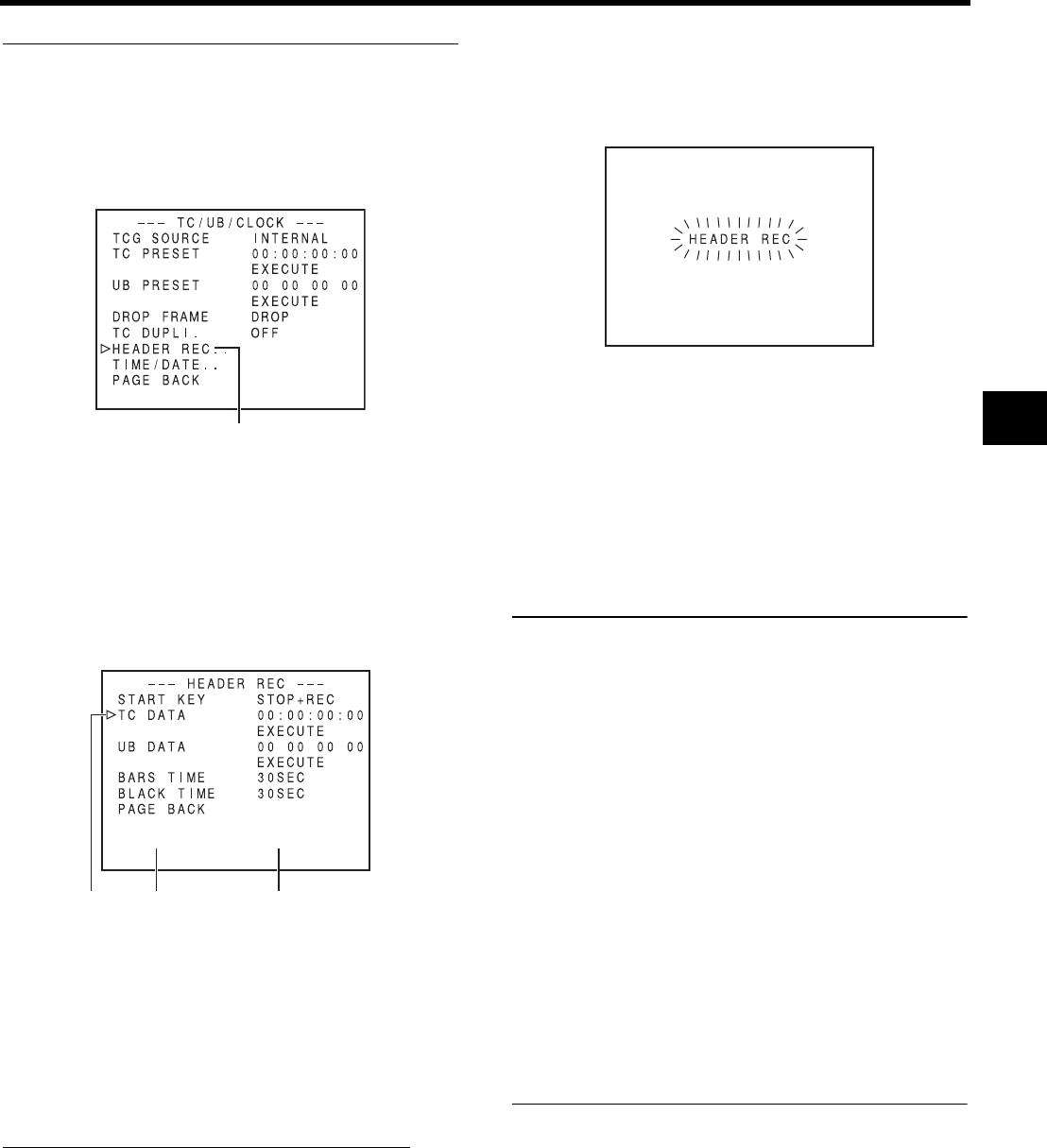
61
How to set the HEADER REC menu screen
1. Display the HEADER REC menu screen.
1Select the TC/UB/CLOCK.. item on the TOP MENU
screen.
2Select the HEADER REC item on the TC/UB/CLOCK
menu screen.
2. Setting the HEADER REC menu screen.
1Select the menu item.
Rotate the SHUTTER dial to align the cursor (K) with
the item to be set, and then press the SHUTTER dial.
• The setting area of the selected item starts blinking.
2Changing the setting value.
Rotate the SHUTTER dial to change the setting, and
then press the SHUTTER dial.
In the case of the TC DATA item and the UB DATA
item, the blinking digit position moves when the SHUT-
TER dial is pressed. When the SHUTTER dial is
rotated, the value of the blinking digit changes. After all
the digits have been set and the SHUTTER dial is
pressed, EXECUTE starts blinking. Press the SHUT-
TER dial once more to confirm the set value.
3. To terminate the setting, press the STATUS button.
Executing the HEADER REC Function
The START KEY item on the HEADER REC menu screen
should be set to STOP+REC.
1. Load the cassette and engage the Record-Standby mode
or the Stop mode.
2. While pressing the STOP button, press the REC/VTR
trigger button.
• The tape automatically rewinds to the beginning, and
HEADER REC operation starts from the beginning of
the tape.
After HEADER REC recording is performed for the
specified duration only, the Record-Standby mode is
engaged automatically.
• During HEADER REC recording, “HEADER REC” is
shown (blinking) on the LCD monitor and in the view-
finder.
• The menu screen is not displayed during HEADER REC
recording.
3. After HEADER REC recording is completed and the
Record-Standby mode is engaged, normal recording
starts when you press the REC/VTR trigger button.
• When the TC GENE. switch is set to either REC or
REGEN, the time code value at the start of the
HEADER REC menu screen.
MEMO
• To stop during HEADER REC operation, press the REC/
VTR trigger button or the STOP button.
• The HEADER REC menu screen cannot be opened dur-
ing HEADER REC recording.
• HEADER REC operation is accepted even during load-
ing of the cassette tape.
• The test tone (1 kHz sine-wave) recorded in the color bar
section will be recorded unrelated to the setting for the
TEST TONE item on the AUDIO/MIC[1/2] menu screen.
• The time code preset on the TC/UB/CLOCK menu
screen becomes invalid when HEADER REC recording
is performed.
• The user’s bits following completion of HEADER REC
recording will be the user’s bits value set on the TC/UB/
CLOCK menu screen.
• The running of the time code following completion of
HEADER REC recording will be in accordance with the
setting of the TC GENE. switch.
FREE RUN : Continuous running.
REC RUN or REGEN: Runs only during REC.
• Camera images are not output to the LCD monitor, view-
finder or video output during REW mode when the
HEADER REC operation begins.
TC/UB/CLOCK menu screen
HEADER REC menu screen
Cursor Item Set value
During HEADER REC
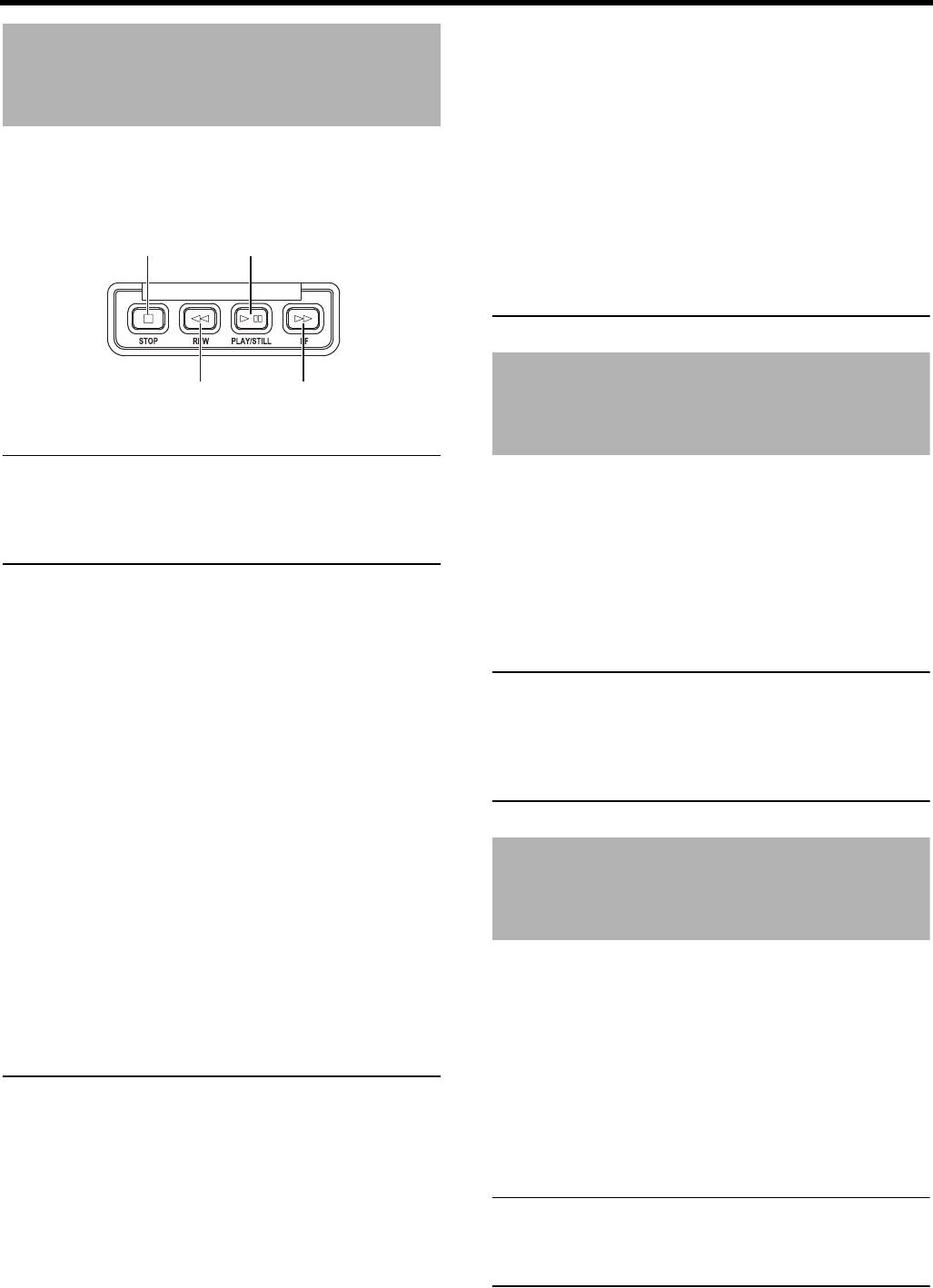
62
PLAYBACK MODE
Playback Procedure
Recorded pictures can be viewed in the viewfinder, or on the
LCD monitor, or on the monitor connected to the video output
connector.
MEMO
The GY-HD250/GY-HD251 can play back the following two
types of videocassettes:
• MiniDV videocassette
• DVCAM videocassette
Tapes recorded in the LP mode cannot be played back.
1. Set the POWER switch to ON.
2. Set this device to the VTR mode.
Press the CAM/VTR button to turn on the VTR indicator.
* Playback is also possible in the Camera mode.
Playback operation becomes possible when the STOP
button is pressed to set the VTR operation mode indi-
cator to indicate STOP.
3. Load the recorded videocassette correctly.
• When the videocassette is loaded, this device enters
the Stop mode.
4. Open the operation cover on the upper section of this
device.
Slide the operation cover to the side to open.
5. Press the PLAY/STILL button.
• Playback starts.
6. Press the PLAY/STILL button to stop playback tempo-
rarily.
• This device enters the still mode.
7. To re-start playback, press the PLAY/STILL button.
8. To stop playback or the still mode, press the STOP but-
ton.
MEMO
• In the VTR mode, the camera image is not output on the
LCD monitor, in the viewfinder or through the video out-
put connector.
• When the still picture mode or stop mode has continued
for a while, this device automatically switches to the tape
protect mode.
• Noise may appear in the picture in the still mode.
• When the automatic tracking function is activated at the
start of the playback mode, digital noise may appear in
the playback image.
• This device does not allow manual tracking adjustment.
• When playing back a tape that was recorded on another
unit, digital noise may appear during playback.
• Following loading of the tape, the built-in head cleaner
will emit a sound while operating. This does not indicate
a malfunction.
• The data recorded for the date and time or time code on
the tape can be shown on the screen. To enable or dis-
able the display is selected on the menu screen:
Fast-Forward, Rewind
Press the FF button in the stop mode to fast forward the
tape. Press the REW button in the stop mode to rewind
the tape. (VTR mode only)
* “SWITCH TO VTR MODE” is displayed and the function
does not work if the “FF” or “REW” buttons are pressed
when Camera mode is in the stop mode.
Press the STOP button to stop fast forwarding or rewind-
ing.
MEMO
• When the tape approaches the end during fast forward-
ing or rewinding, the tape speed decelerates to protect
the tape.
• The time required for fast forwarding and rewinding may
become longer when used in a cold environment. This is
not a malfunction.
Search
Press the FF button in the play mode or still mode to
search the tape in the forward direction. Playback takes
place while fast forwarding.
Pressing the REW button executes search of the tape in
the reverse direction. Playback takes place while rewind-
ing.
(Each press on the button switches the speed to ×2, ×5,
and ×10.)
Press the PLAY/STILL button to resume normal playback.
Press the STOP button to stop.
MEMO
• To output sound during the search, set the SEARCH
AUDIO [DV] item on the AUDIO menu screen to ON.
• Block noise may appear in the picture or the image may
freeze during the search.
Tape protect mode : Drum rotation is stopped in order to
protect the tape.
STOP button PLAY/STILL button
REW button FF button
Display of date and time : TIME/DATE menu screen
Display of time code : LCD/VF[1/2] menu screen
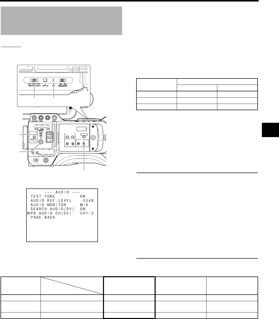
63
Outputting Audio
Setting
Confirm that the GY-HD250/GY-HD251 is in the VTR mode.
(VTR indicator: On)
Earphone terminal output audio
Audio output is as shown in the table below depending on
the MONITOR SELECT switch and AUDIO MONITOR
and PB AUDIO CH [DV] settings on the AUDIO menu
screen.
1. Display the AUDIO menu screen.
Select the AUDIO item on the TOP MENU screen.
2. Set the AUDIO menu screen.
• PB AUDIO CH [DV] Items
For HDV format, audio is output to CH1 and CH2 no matter
the settings.
3. Either of the following operations returns you to the nor-
mal screen.
• Press the STATUS button
or
• Return to the TOP MENU screen, select the EXIT item
and press the SHUTTER dial.
MEMO
• The DV format is capable of recording up to 4 channels
when the 12-bit, 32 kHz sampling frequency is
employed. The GY-HD250/GY-HD251 records audio on
the two channels CH-1 and CH-2. (4-channel recording
is possible in the case of DV input.)
When the GY-HD250/GY-HD251 is used for playback of
a tape that was recorded on another unit with audio
recorded on the CH-3 and CH-4 channels, the PB
AUDIO CH [DV] item on the AUDIO menu screen must
be set.
After-recording on the CH-3 and CH-4 channels is not
possible.
• The PB AUDIO CH [DV] item is also valid for embedded
audio.
• The sampling frequency for embedded audio is 48 kHz.
USER 3USER 2USER 1
STATUS
MENU
2
1
ND FILTER
REC
OFF
ON
POWER
WHT.BAL
AUTO
AUDIO
LEVEL
AUTO
CH-1 CH-2
VF BRIGHT
CH-2
CH-1
-
+
AUDIO SELECT
MANU
AUTO
TC
LCD BRIGHT
DISPLAY
TC
UB
FREE
REGEN
GENE.
REC
CAM/VTR
AUDIO menu screen
MONITOR
SELECT switch VTR indicator
SHUTTER
dial
STATUS
button
CAM/VTR button
CH1/2 : To reproduce the sound (CH-1, CH-2)
recorded during shooting.
MIX : To reproduce the sound recorded during
shooting (CH-1, CH-2) and the after-
recorded sound (on CH-3 and CH-4)
simultaneously.
CH3/4 : To reproduce the sound after-recorded
on CH-3 and CH-4.
PB AUDIO CH [DV] AUDIO OUT connector
CH-1 CH-2
CH1/2 CH1 CH2
MIX CH1+CH3 CH2+CH4
CH3/4 CH3 CH4
MONITOR
SELECT
PB AUDIO CH [DV]
AUDIO MONITOR
CH1/2 MIX CH3/4
CH-1 - L/R: CH1 L/R: CH1+CH3 L/R: CH3
BOTH MIX
STEREO
L/R: CH1+CH2
L: CH1 R:CH2
L/R: CH1+CH2+CH3+CH4
L: CH1+CH3 R: CH2+CH4
L/R: CH3+CH4
L: CH3 R: CH4
CH-2 - L/R: CH2 L/R: CH2+CH4 L/R: CH4
* In HDV format, you can only select the settings within the bold frame.
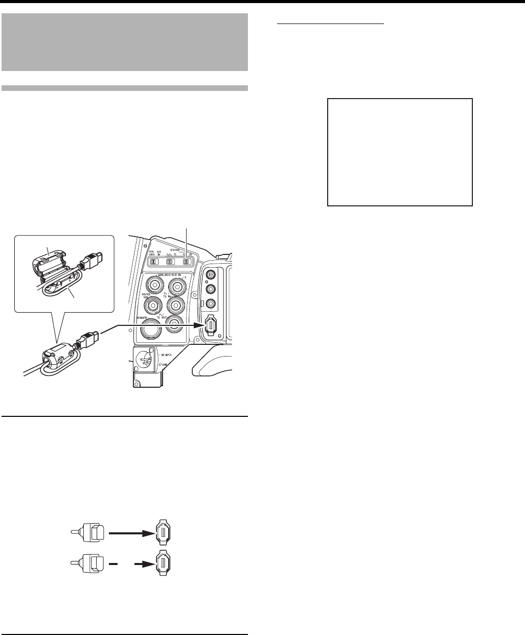
64
USING EXTERNAL COMPONENTS
Connecting the Video
Signal Cables
Connecting the IEEE1394 Cable
To reduce the emission of unwanted radio waves, be sure to
attach the provided clamp filter as shown in the figure below.
• Attach the clamp filter as close to this device as possible,
as shown in the figure.
• Set the IEEE1394 switch on the left panel of this device.
CAUTION
When connecting the IEEE1394 cable from/to Camcorder,
VCR and other IEEE1394 device, make sure the following
instructions, otherwise the IEEE1394 circuit device may be
destroyed.
• Turn the power of both devices OFF and connect the
IEEE1394 cable.
• Do not insert incorrectly (in reverse) the IEEE1394 cable
end to IEEE1394 port of both devices.
• Do not connect the IEEE1394 cable under the condition
of static electricity.
• Turn the power of both devices OFF when changing the
IEEE1394 switch from/to HDV/DV.
Displaying Alarms
• CHANGE 1394 SWITCH
Displayed when the setting for the input/output video format
from the IEEE1394 connector and the setting for the
IEEE1394 switch are different.
Set the IEEE1394 switch so it matches the video format.
DV : DV format
HDV : HDV format
IEEE 1394
CH2-AUDIO OUT-CH1 VIDEO
IEEE1394 switch
Clamp filter
Wind once
IEEE 1394IEEE 1394
X
CHANGE 1394 SWITCH
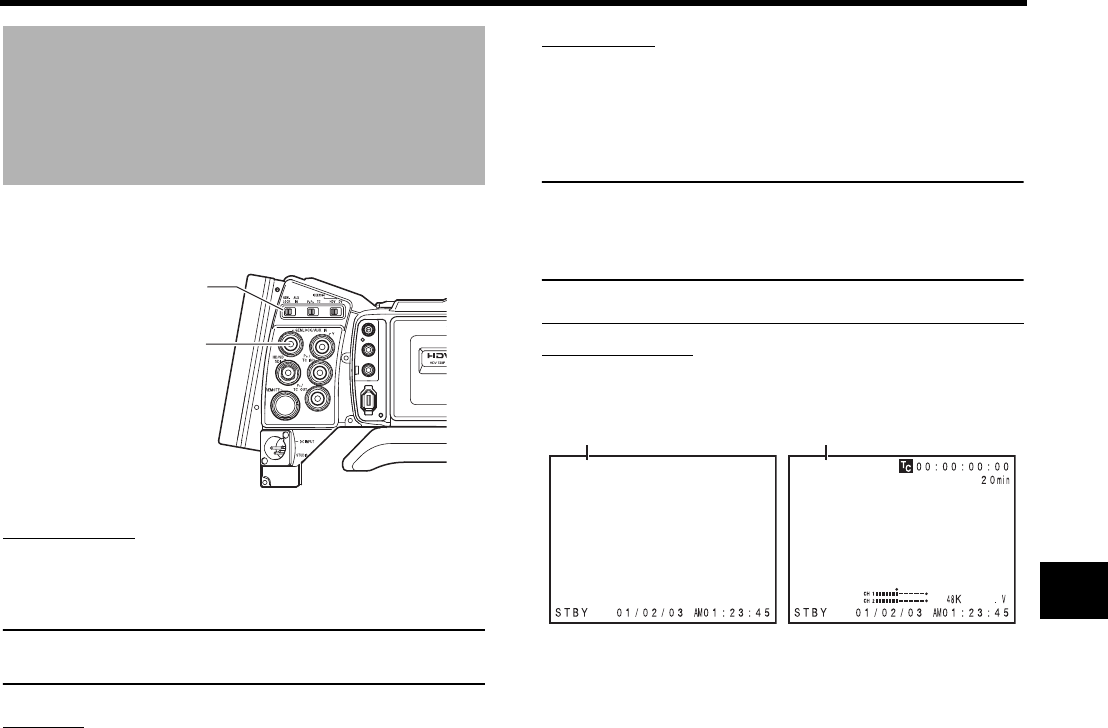
65
Recording Composite
Video Signals from an
External Device
This device features an AUX IN terminal and can record
composite video signals from external devices.
Connection
Input analog composite video signals from an external
device to the GENLOCK/AUX IN terminal.
MEMO
Input composite video signals with no jitter.
Input level: 1.0V ± 0.3V (p-p)
Setting
Set this device to camera mode:
If the VTR indicator is lit, press the [CAM/VTR] button and
turn off the indicator.
Set the GENLOCK/AUX IN switch to AUX IN.
Set REC on the VIDEO FORMAT[1/2] menu screen as fol-
lows.
U model: DV-60I
E model: DV-50I
Set SET UP item on the VIDEO FORMAT[2/2] menu
screen as follows. (Only for U model)
ON : Set to this when input analog signals include the
setup signal.
OFF : Set to this when input analog signals do not include
the setup signal.
Operation
Start and stop recording with the REC/VTR trigger button.
• EE images of input signals are output in DV-60I (U
model) or DV-50I (E model) formats from the various
image output terminals.
CAUTION
• Recording cannot be checked using the lens RET button
when recording external image signals.
• Do not touch GENLOCK/AUX IN switch during record-
ing.
Status Screen Display on the LCD Screen
or Viewfinder
• “AUX” is displayed at the top left with signal format (DV60I
or DV50I).
IEEE 1394
CH2-AUDIO OUT-CH1 VIDEO
GENLOCK/AUX IN switch
GENLOCK/AUX IN terminal
DV-60I AUX
“AUX” display “AUX” display
STATUS 0 screen STATUS 1 screen
DV-60I AUX
12.0
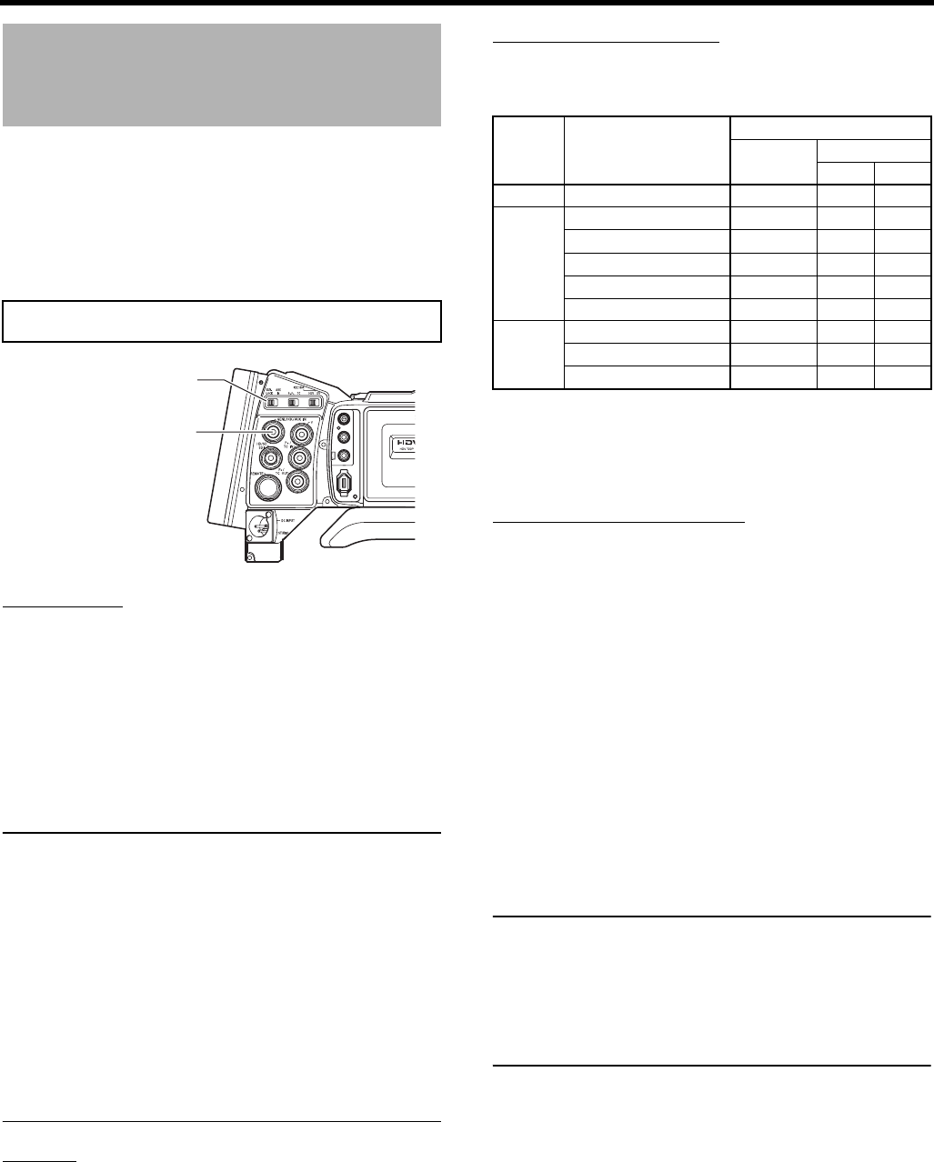
USING EXTERNAL COMPONENTS
66
Using GENLOCK Func-
tions
This device features a GENLOCK IN terminal. Input external
synchronization signals in the GENLOCK IN terminal to syn-
chronize camera images or playback images with external
signals.
Additionally, the H (horizontal) and SC (subcarrier) phase
adjustments can be performed on image signals of this
device for external synchronization signals from the GEN-
LOCK menu screen.
Connection
During Standby or Stop mode, input synchronization sig-
nals from a Sync signal generator to the GENLOCK/AUX
IN terminal.
The following synchronization signals are applicable.
SD synchronization signal: BB (Black burst) signals
SMPTE170M (RS-170A)-compliant for NTSC
ITU-R BT.470-6-compliant for PAL
HD synchronization signal: HDTV Tri-sync signals
SMPTE296M-compliant for HD720p
SMPTE274M-compliant for HD1080i
CAUTION
• When the FRAME RATE is set to 60/30 or 24 in the
VIDEO FORMAT[1/2] menu screen, input a 59.94 Hz
synchronization signal (vertical synchronization). 50 Hz/
60 Hz synchronization signals cannot be synchronized.
If the FRAME RATE is set to 50/25, input a 50 Hz syn-
chronization signal. 59.94 Hz/60 Hz synchronization sig-
nals cannot be synchronized.
• Do not connect or disconnect the cable during recording
or playback.
• When the power is turned on while the external synchro-
nization signal is input, a vertical vibration occurs for a
few seconds. This is not a malfunction.
• VTR playback signals with jitter cannot be synchronized
with this device.
Setting
Set this device to Camera mode.
Set the GENLOCK/AUX IN switch to GENLOCK.
• When the camera image is locking to external synchro-
nization signals, “SYNC LOCKING” is displayed on the
screen. When locking to external synchronization sig-
nals is complete, the indication disappears and you can
enter recording mode.
Synchronized Signals
The synchronized signal differs depending on the input sync
signal.
Refer the table below.
SC : Subcarrier phase H: Horizontal phase
V : Vertical phase F : Field phase
Adjust SC PHASE and H PHASE in the above table from the
GENLOCK menu screen.
Adjust SC and H PHASE
1. Display the GENLOCK menu screen.
Follow the steps in “Setting Menu Screens” on page 75
and proceed as follows.
MENUrOTHERSrGENLOCK
2. In the GENLOCK menu screen, select the item to per-
form phase adjustment for and adjust.
SD H PHASE : Adjust the H phase in SD analog signals.
(During BB signal input)
HD H PHASE : Adjust the H phase in HD analog and SD/
HD SDI signals. (During Tri-sync signal
input, PHASE of SD analog signals are
simultaneously adjusted in HD H PHASE
item.)
SC PHASE : Adjust the SC phase in composite and
YC signals.
For details, refer to “GENLOCK Menu Screen” on
XSee page 99.
MEMO
• H PHASE cannot be adjusted during playback or record-
ing.
• IEEE1394 output stops while H PHASE is being
adjusted.
• When values for SD H PHASE or HD H PHASE is
changed, the images cannot be produced properly
momentarily. This is not a malfunction.
GENLOCK functions are only valid in Camera mode. They do not
work in VTR mode.
IEEE 1394
CH2-AUDIO OUT-CH1 VIDEO
GENLOCK/AUX IN switch
GENLOCK/AUX IN terminal
Terminal Video signal
Input sync signal
BB Tri-sync
720p 1080i
VIDEO Composite SC,H,V,F V V,F
Y/PB/PR
SD Component H,V,F V V,F
HD Component 720p V H,V V
HD Component 1080i V,F V H,V,F
SD RGB H,V,F V V,F
SD Y/C SC,H,V,F V V,F
HD/SD-
SDI
SD-SDI H,V,F V V,F
HD-SDI 720p V H,V V
HD-SDI 1080i V,F V H,V,F
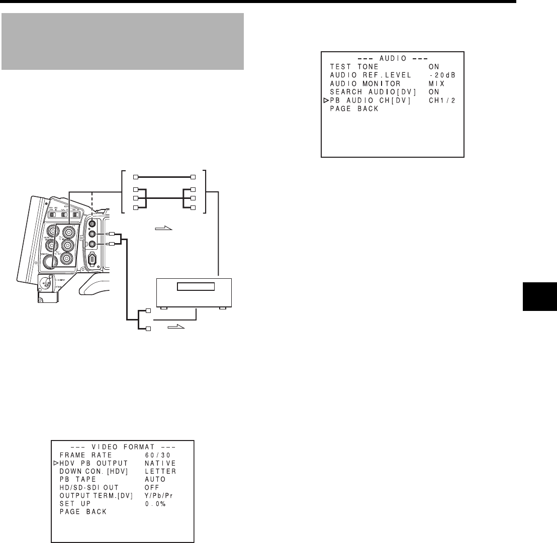
67
Dubbing with AV Devices
By connecting the video signal output terminal and the
AUDIO OUTPUT terminal on GY-HD250/GY-HD251 to an AV
device, analog signal dubbing is possible.
1. Connect the cables.
2. Turn both devices on.
3. Set this device to VTR mode.
Press the CAM/VTR button. The VTR indicator lights.
4. Set the video output.
Set the VIDEO FORMAT menu screen. XSee page 77.
• HDV PB OUTPUT item:
Set the video format to be output from the video output
terminal during tape playback.
• PB TAPE item:
Select whether to automatically detect the playback tape
video format or play back only a particular format.
Normally, use the “AUTO” setting.
• OUTPUT TERM. [DV] item:
Set component, RGB or Y/C signals for the output image
signals of the [Y/PB/PR] terminal. (Only for DV format)
5. Set the audio output. XSee page 63.
Set the AUDIO menu screen. XSee page 87.
• PB AUDIO CH [DV] item:
Set the audio channel to be output.
6. Insert the videocassettes.
7. Press the PLAY/STILL button on the GY-HD250/GY-
HD251 to start playback.
8. Start recording on the recording unit.
For details, see the instructions to the unit used for
recording.
9. When dubbing is completed.
Stop recording on the recording unit, and then press the
STOP button on the GY-HD250/GY-HD251 to stop play-
back.
IEEE 1394
CH2-AUDIO OUT-CH1 VIDEO
Signal flow
Recording unit
AUDIO
OUTPUT
connector
Signal flow
Composite cable
or
Component cable
VIDEO FORMAT menu screen
GY-HD250/GY-HD251 : Insert the recorded videocas-
sette.
Recording unit : Insert the videocassette to be
dubbed to.
AUDIO menu screen
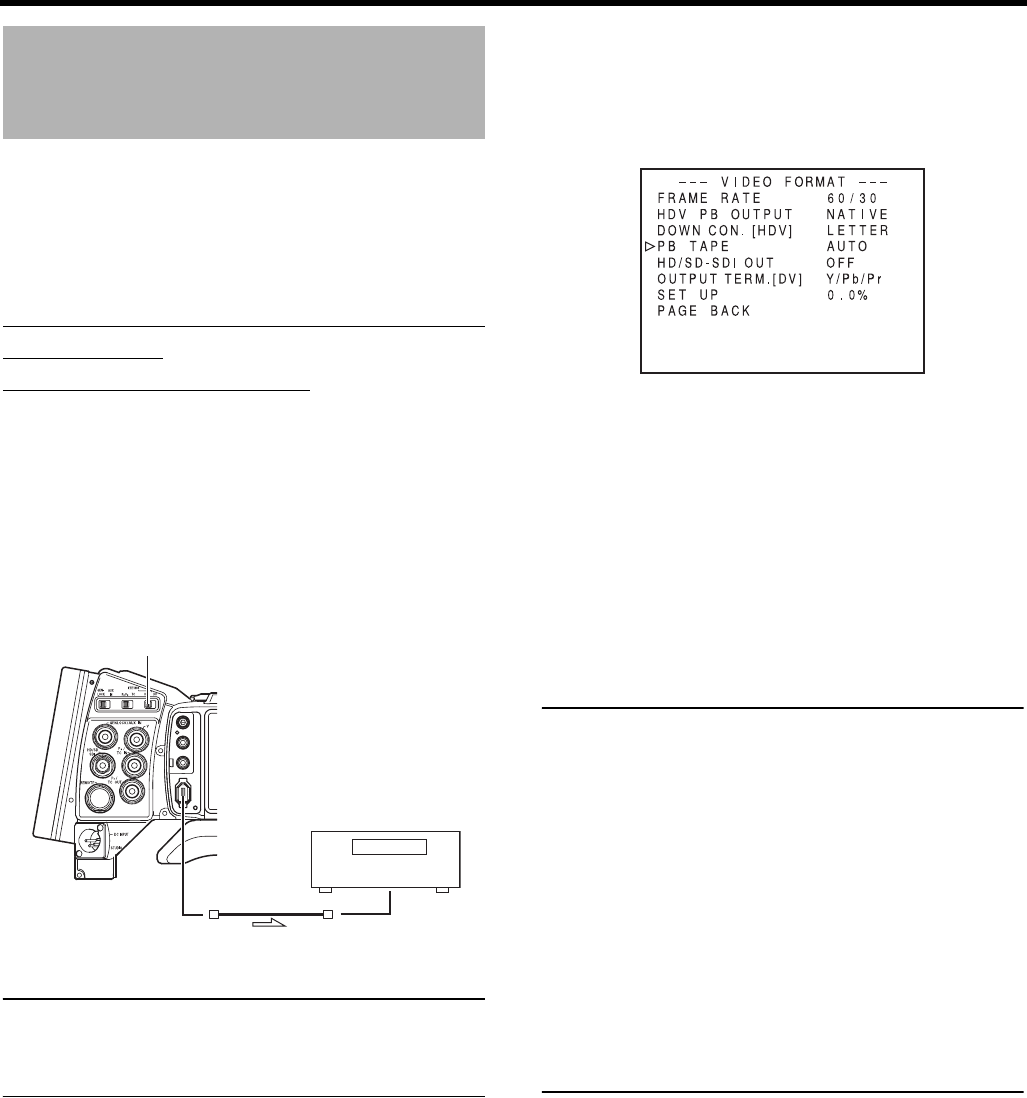
USING EXTERNAL COMPONENTS
68
HDV/DV Dubbing
Connecting the GY-HD250/GY-HD251 to another video com-
ponent equipped with HDV/DV connector (IEEE1394 stan-
dard) using a IEEE1394 cable (optional) enables dubbing of
digital signals with high picture quality and high-quality
sound.
Using the GY-HD250/GY-HD251 as the
playback unit
(Dubbing to another video)
1. Set the IEEE1394 switch on the left panel of this device.
2. Connect the IEEE1394 cable.
3. Turn both devices on.
4. Set this device to VTR mode.
Press the CAM/VTR button. The VTR indicator lights.
CAUTION
• Set the IEEE1394 switch on both devices to either HDV
or DV.
• Start recording after making sure that both devices are
properly connected.
5. Set the PB TAPE item on the VIDEO FORMAT menu
screen. XSee page 79.
Select whether to automatically detect the playback tape
video format or play back only a particular format.
Normally, use the “AUTO” setting.
6. Insert a videocassette tape.
7. Press the PLAY/STILL button on GY-HD250/GY-HD251
to start playback.
8. Start recording on the recording device.
See the recording device user manual for more informa-
tion.
9. When dubbing is finished, stop recording on the record-
ing device, press the STOP button on this device, and
stop the playback.
MEMO
• Switch the IEEE1394 switch when this device is OFF.
• When you dub still images, they are low resolution
images. Noise may also enter the audio.
• Operations may differ depending on the features and
specifications of the connected device, and operations or
data exchange may not be possible even if the devices
are connected.
• If noise appears on the screen or the audio cuts out, re-
connect the IEEE1394 cable or turn the GY-HD250/GY-
HD251 on again.
• If you turn the power to the device connected to the
IEEE1394 connector on and off or switch the video input,
noise may occur in the audio. If you perform this type of
operation, set the speaker volume as low as possible on
the audio device connected to this device.
• Recording may not be possible in some cases even if the
recorder is equipped with a IEEE1394 connector.
DV : When dubbing in DV format
HDV : When dubbing in HDV format
IEEE 1394
CH2-AUDIO OUT-CH1 VIDEO
IEEE1394 cable
1.
IEEE1394 switch
Signal flow
2.
Recording unit
GY-HD250/GY-HD251 : Recorded videocassette tape
Recording unit : Videocassette you want to dub
VIDEO FORMAT menu screen
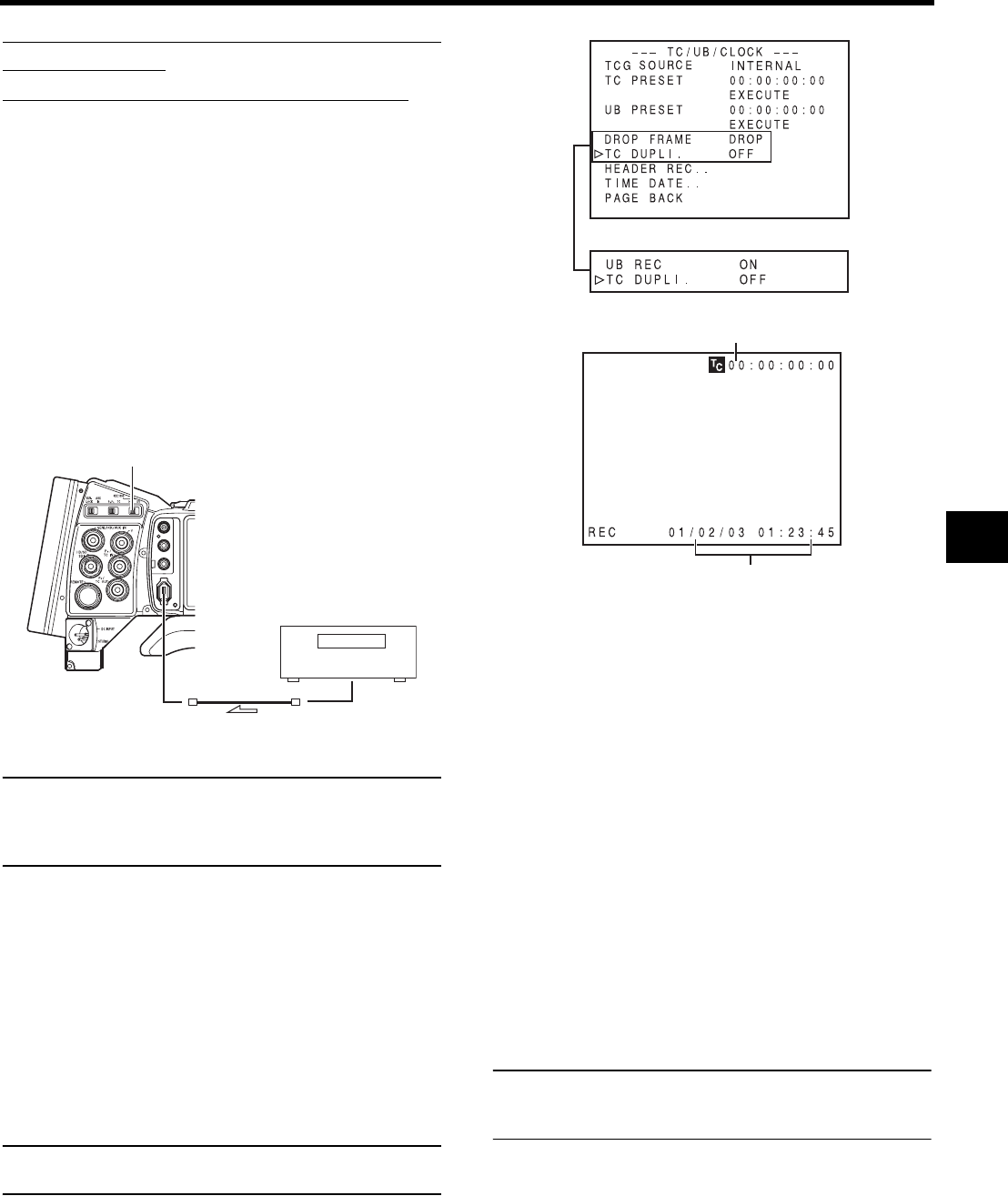
69
When Using the GY-HD250/GY-HD251 as
Recording Unit
(Dubbing From Another Videocassette)
1. Set the IEEE1394 switch on left side of the GY-HD250/
GY-HD251.
2. Connect the units with the IEEE1394 cable.
3. Turn ON both units.
4. Place the GY-HD250/GY-HD251 in the VTR MODE.
Press the CAM/VTR button to turn on the VTR indicator.
5. Set the frame rate.
Set the FRAME RATE item (60/30, 50/25, 24) on the
VIDEO FORMAT[1/2] menu to match the HDV/DV signal
frame rate input from the IEEE1394 connector.
XSee page 77.
CAUTION
• Set the IEEE1394 switch on both devices to either HDV
or DV.
• Start recording after making sure that both devices are
properly connected.
6. Set the time code and user bit recording.
Set the TC DUPLI. item on the TC/UB/CLOCK menu
screen.
MEMO
In HDV format, the UB set in this device is recorded regard-
less of the setting.
7. Insert the videocassettes.
8. Start playback on the playback unit.
For details, see the instructions to the unit used for play-
back.
• The playback picture from the playback unit appears
on the GY-HD250/GY-HD251’s LCD monitor and view-
finder screen.
9. Press the REC/VTR trigger button on the GY-HD250/GY-
HD251 to start recording.
To temporarily pause the recording, press the REC or
VTR trigger button.
To restart the recording, press the REC or VTR trigger
button again.
10.When dubbing is completed.
Press the REC/VTR trigger button or the STOP button on
the GY-HD250/GY-HD251 to stop recording, and then
stop playback on the playback unit.
MEMO
Depending on the player, sound may not be heard momen-
tarily from this device when switching modes from STILL to
PLAY.
DV : When dubbing in DV format
HDV : When dubbing in HDV format
OFF : Records the TC/UB set in this
device.
ON : Records the TC/UB for the
IEEE1394 input.
Date and time data : Records the data sent from the
playback device in DV format.
Records the data of the internal
clock in HDV format.
IEEE 1394
CH2-AUDIO OUT-CH1 VIDEO
IEEE1394 cable
1.
IEEE1394 switch
Signal flow
2.
Recording unit
GY-HD250/GY-
HD251
: Insert the videocassette to be dubbed
to.
Playback unit : Insert the recorded videocassette.
TC/UB
Date and Time
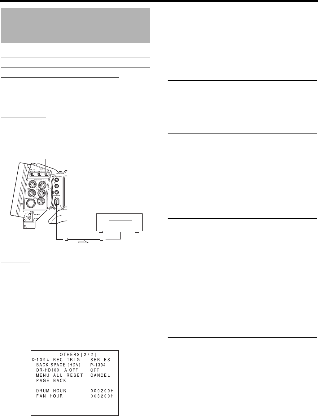
USING EXTERNAL COMPONENTS
70
Backup Recording
Backup Recording of the GY-HD250/GY-
HD251’s Camera Image and Sound
Through the IEEE1394 Connector
The GY-HD250/GY-HD251’s camera image and sound can
be recorded for backup on another component that is
equipped with IEEE1394 connector.
Connections
Use the GY-HD250/GY-HD251 as the master unit.
Connect the master unit and the backup unit with a
IEEE1394 cable.
Settings
Master unit (GY-HD250/GY-HD251)
1. Set the IEEE1394 switch on left side of the GY-HD250/
GY-HD251.
2. Place in Camera mode.
3. Set the 1394 REC TRIG. item on the OTHERS[2/2] menu
screen. XSeepage97.
For HDV mode, set the BACK SPACE [HDV] item.
XSee page 97.
Backup unit
• Place in HDV/DV signal input mode.
* Depending on the used component, it may be neces-
sary to set “REMOTE SELECT”.
• When BR-HD50 is used, set the Backup Recording
function to OFF.
Also, set REM SEL HDV/DV in the REMOTE[1/2] menu
of the BR-HD50 to ON or LOC+REM.
• Insert the tape and set to STOP or REC PAUSE status.
CAUTION
• Set the IEEE1394 switch on both devices to either HDV
or DV.
• Start recording after making sure that both devices are
properly connected.
• If the RET button is pressed during backup recording,
output from the IEEE1394 terminal is stopped, the image
is switched to the image recorded on this device, inter-
rupting the backup recording image.
Operation
Start and stop of recording on the backup unit takes place in
accordance with the operation of the REC/VTR trigger button
on the master unit.
(Depending on the GY-HD250/GY-HD251 or the backup unit,
the image, audio, and/or time code may deviate from what
they should be at the points where the recording is started or
stopped.)
MEMO
• When the backup recording is started, the “TRIGGER
TO DV” or “TRIGGER TO HDV” indication is shown on
the LCD or in the viewfinder for approx. 3 seconds.
• When the Series Recording function of BR-HD50 is
used, the GY-HD250/GY-HD251’s 1394 REC TRIG. item
should be set to OFF.
• If the backup device is equipped with a feature to record
time codes input from the IEEE1394 connector (TC
DUPLICATE feature), time code data the same as on the
master side can be recorded.
If the master unit tape is paused or stopped when the
master unit time code running mode is in REC RUN
mode, the time code for the slave unit stops.
• When using BR-HD50 as a backup device and switching
GY-HD250/GY-HD251 from the playback mode to the
record mode, noise will be noticed on the monitor output
screen of BR-HD50 (backup will be correctly recorded).
DV : When backup in DV format
HDV : When backup in HDV format
IEEE 1394
CH2-AUDIO OUT-CH1 VIDEO
IEEE1394 cable
IEEE1394 switch
Signal flow
Master unit
GY-HD250/
GY-HD251
Backup unit
1.
OTHERS[2/2] menu screen
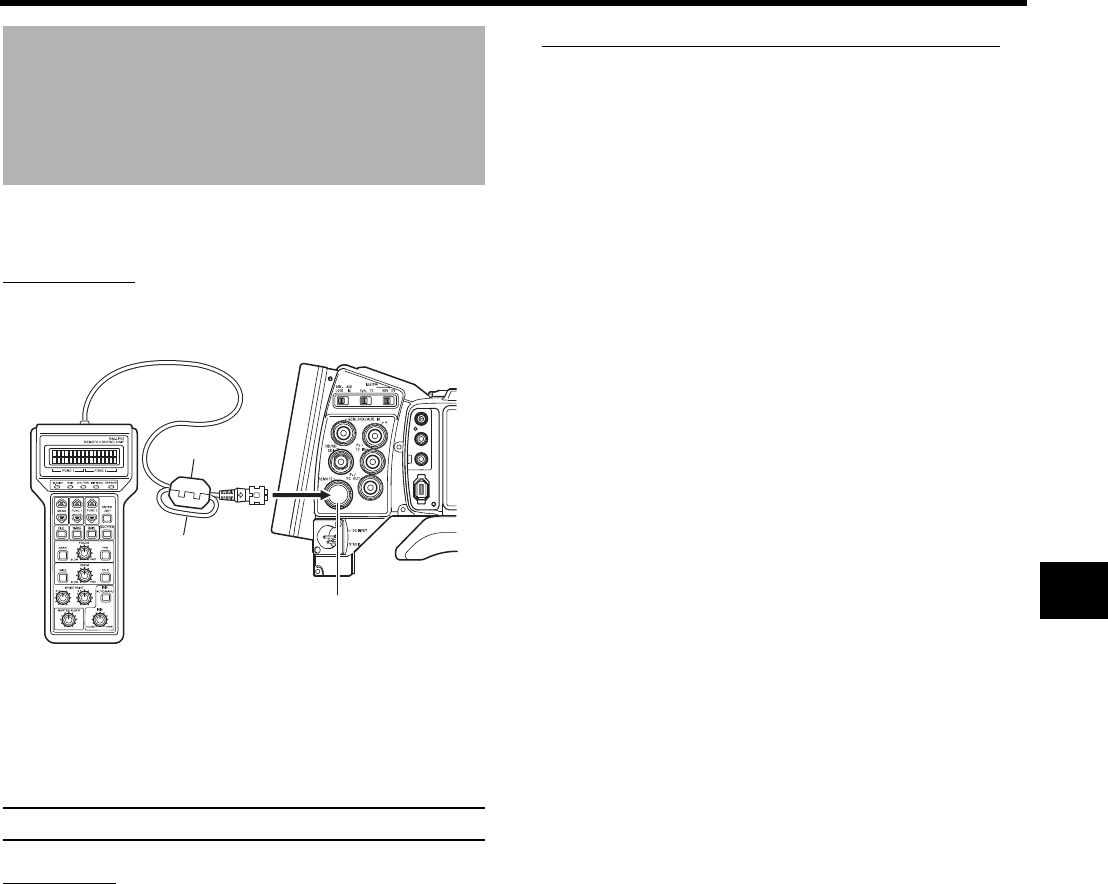
71
Connect a Remote Con-
trol Unit (RM-LP55/RM-
LP57)
Set camera switch functions with the remote control unit
(RM-LP55/RM-LP57).
Connection
Connect the remote control unit cable to the REMOTE termi-
nal.
• Attach the clamp filter included with the remote control unit
to the remote cable.(The clamp filter can be substituted
with the clamp filter included with this device.)
Consult your JVC dealer if you do not have a clamp filter.
CAUTION
Turn the power OFF when connecting.
Operation
1. Turn the device ON.
2. Turn ON the OPERATE switch on remote control unit to
activate the remote control unit.
See page 72 for details on functions that can be operated
with the remote control unit.
Notes on Using the Remote Control Unit
• When the switch function of this device and the remote
control unit are the same, the remote control switch func-
tion is prioritized.
• FOCUS and ZOOM cannot be adjusted with the remote
control unit.
• Shutter speed slightly differs from the value displayed on
this device.
• Shutter Speed in 24p Mode
When this device is in 24p mode, shutter speed cannot be
set to 1/60 (U model) or 1/50 (E model) with the remote
control unit.
Even if shutter speed is set to 1/60 or 1/50 with the remote
control unit when in 24p mode, the shutter speed for the
device is 1/48.
• When H PHASE adjustment is performed with the remote
control unit, only H PHASE of SD signal operates.
• When adjusting H PHASE of SD signal with the remote
control unit, it cannot be set outside the range of SD H
PHASE in the GENLOCK menu screen. XSee page 99.
• AUTO WHITE Function
When the device is in VTR mode, AUX IN mode, during
playback or HEADER REC, the AUTO WHITE function
does not work even if the auto white operation is per-
formed with the RM-LP55 and RM-LP57.
In the case of the RM-LP55, “LOW LIGHT ERROR” is dis-
played on the LCD screen of the RM-LP55.
IEEE 1394
CH2-AUDIO OUT-CH1 VIDEO
RM-LP55
REMOTE
Wind once
Clamp filter
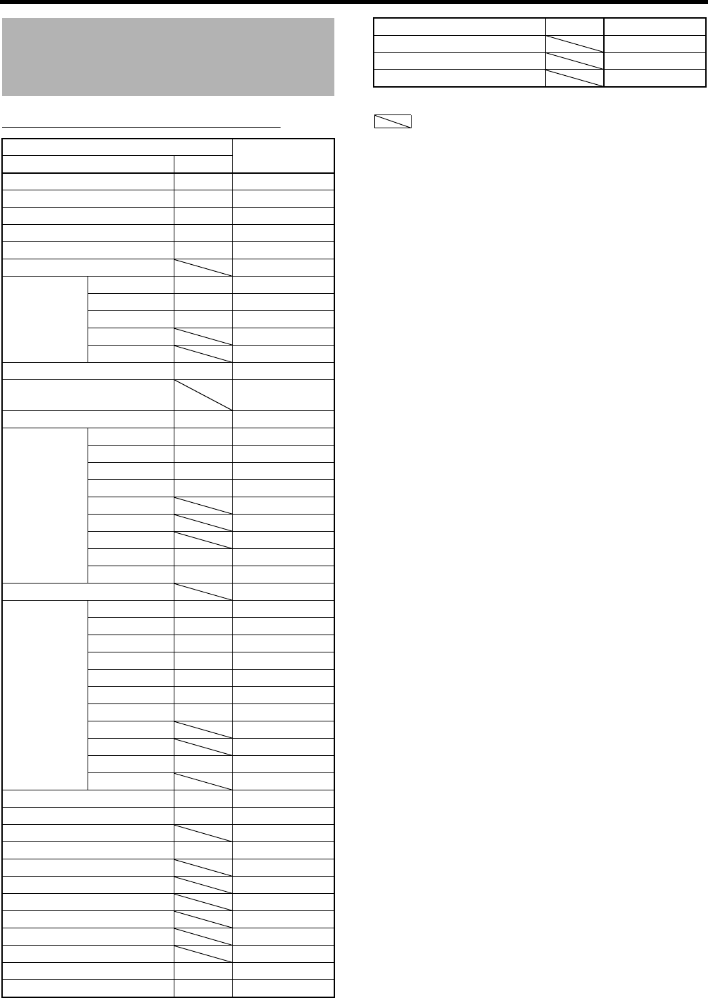
USING EXTERNAL COMPONENTS
72
Connect a Remote Control Unit
(RM-LP55/RM-LP57) (Cont’d)
Remote Control Unit Functions List
*1Only when frame rate is 60p, 60i, 30p, or 24p
*2Only when frame rate is 50p, 50i, or 25p
Function Action
RM-LP55 RM-LP57
BARS [OFF/ON] qG
CONTOUR [OFF/ON] qG
CONTOUR V/H LEVEL qG
IRIS [MANU/AUTO] qG
IRIS LEVEL qG
IRIS DETECT X
WHT.BAL AUTO1 qG
AUTO2 qG
FAW qG
PRESET G
MANU G
AUTO WHITE qG
MANUAL WHITE BALANCE R/B
LEVEL G
PAINT R/B LEVEL qG
GAIN 0dB qG
6dB qG
9dB qG
12dB qG
LOLUX X
–3dB X
–6dB X
ALC+EEI qG
ALC qX
NEGA [OFF/ON] X
SHUTTER NORMAL qG
1/100 qG *1
1/120 qG *2
1/250 qG
1/500 qG
1/1000 qG
1/2000 qG
1/4000 G
1/10000 G
EEI qX
V.SCAN X
ZOOM qX
FOCUS qX
HI-RESO [OFF/ON] X
MASTER BLACK LEVEL qG
GAMMA [OFF/ON] X
GAMMA MASTER LEVEL X
KNEE MASTER LEVEL X
TITLE [OFF/ON] X
TITLE POSITION X
TITLE CLEAR X
H PHASE qG
SC COARSE [0°/90°/180°/270°] qG
SC FINE qG
RANDOM SHUTTER X
VARIABLE SHUTTER LEVEL X
SLOW SHUTTER LEVEL X
q: Same as RM-LP55 G: Available
: None X: Not available
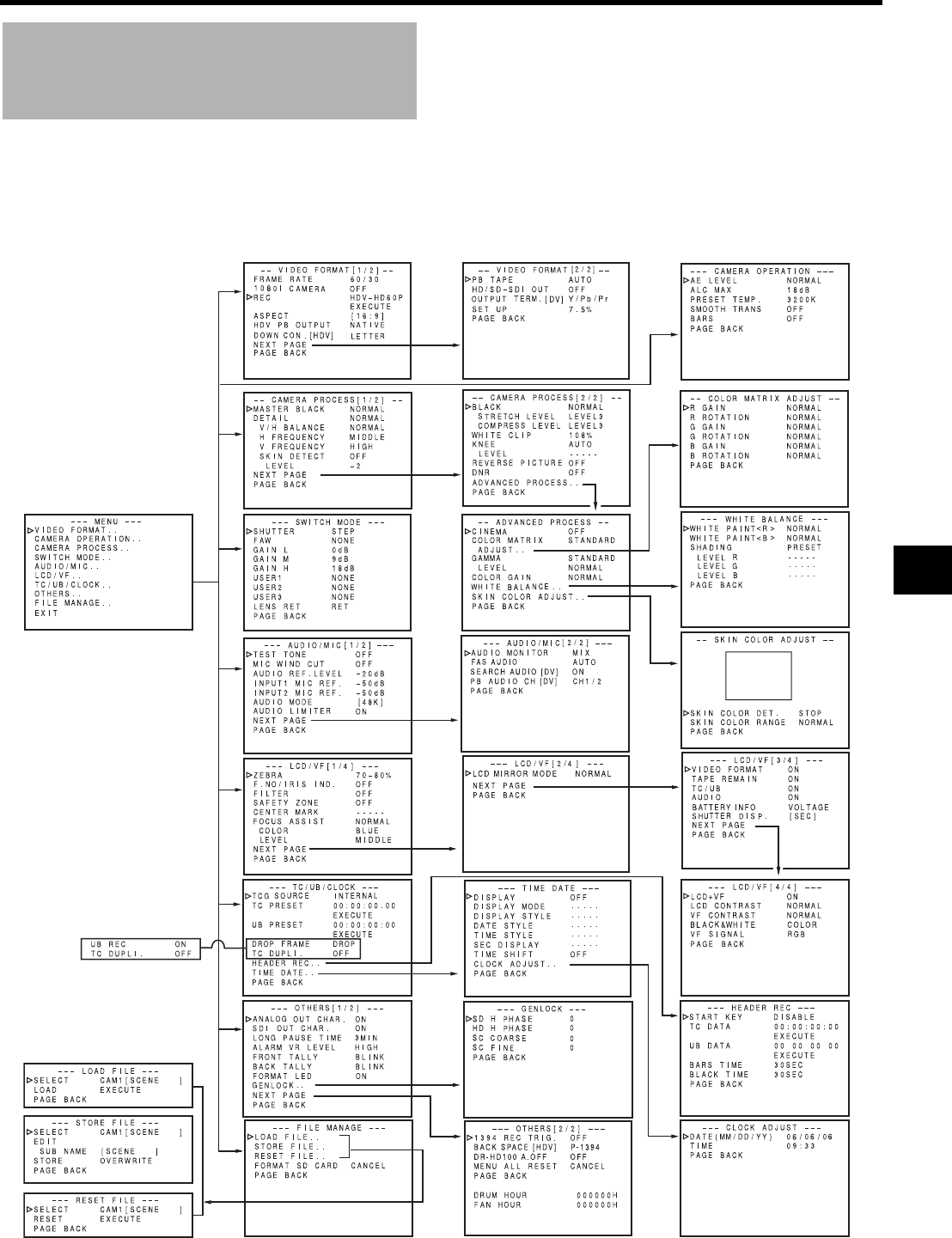
73
MENU SCREENS
Menu Screen Configura-
tion
The Menu Screen consists of multiple layers of menu screens as shown below. The menu screen to be set is selected from the
TOP MENU in accordance with the function or purpose.
The items on the menu screens differ with the Camera mode and the VTR mode. The contents of set items are stored in the GY-
HD250/GY-HD251’s memory and are retained even when the power is turned off.
The FILE MANAGE menu screen can be used to store the menu setting contents on the GY-HD250/GY-HD251 or SD memory card.
Camera Mode
TOP MENU screen (CAM)
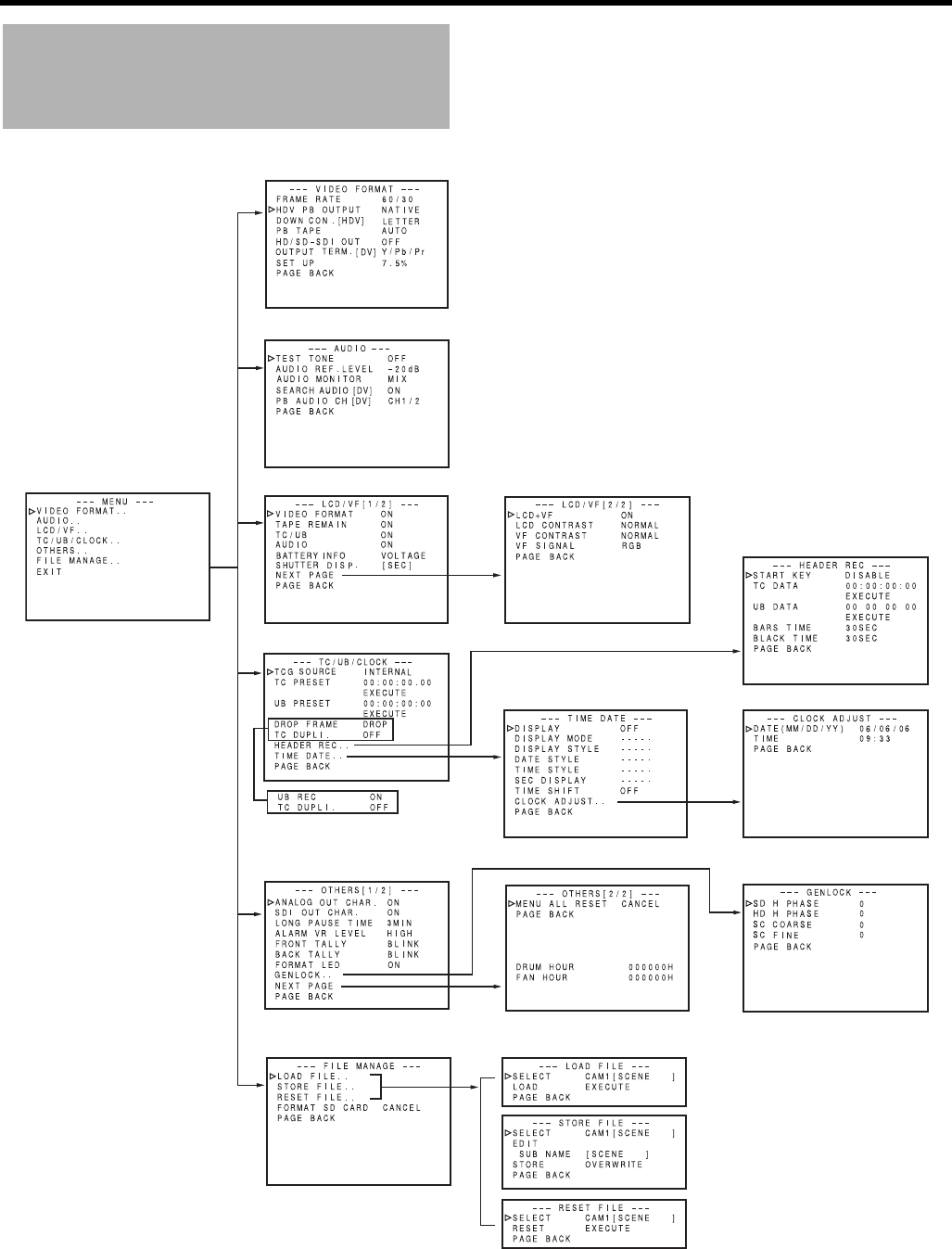
MENU SCREENS
74
Menu Screen Configuration
(Cont’d)
VTR Mode/IEEE1394 Input Mode
TOP MENU screen (VTR)
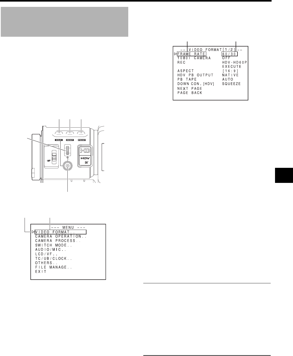
75
Setting Menu Screens
Make the settings while observing the LCD monitor or the
viewfinder screen.
If the ANALOG OUT CHAR. item or SDI OUT CHAR item on
the OTHERS[1/2] screen is set to ON, the menu screen can
also be viewed on a monitor connected to the video signal
output connector.
1. Set the POWER switch to ON.
2. Set the mode of the GY-HD250/GY-HD251 with the CAM/
VTR button. (Camera mode or VTR mode)
3. Press the STATUS button for 1 second or longer.
• The TOP MENU screen appears.
4. Select the menu screen to be set.
Rotate the SHUTTER dial to align the cursor (K) with the
menu screen to be set, and then press the SHUTTER
dial.
• The selected menu screen appears.
5. Select the menu item on the menu screen.
Rotate the SHUTTER dial to align the cursor (K) with the
item to be set, and then press the SHUTTER dial.
• The setting area of the selected item starts blinking,
and the setting can now be made.
6. Change the setting.
Rotate the SHUTTER dial to change the setting, and then
press the SHUTTER dial.
• The setting area stops blinking and the setting is
entered.
To change multiple items, repeat the procedures in steps
5. and 6. above.
7. Return to the TOP MENU screen.
Rotate the SHUTTER dial to align the cursor (K) with the
PAGE BACK item, and then press the SHUTTER dial.
To change settings on other menu screens, repeat the
procedures in steps 4. to 7. above.
To save the set contents in FILE, select the FILE MAN-
AGE menu screen and perform the operations for saving
to file.
XSee “FILE MANAGE Menu Screen” on page 100.
8. To return to the normal screen after completing the set-
tings, use either of the following methods.
Press the STATUS button
or
Return to the TOP MENU screen and align the cursor (K)
with the EXIT item, and then press the SHUTTER dial.
MEMO
• While the menu screen is being displayed, the USER1,
USER2 and USER3 buttons can also perform menu
operations.
USER1 button : Raises the cursor (K)/Changes the set-
ting
USER2 button : Lowers the cursor (K)/Changes the set-
ting
USER3 button : Confirms the menu item/Confirms the
setting
• The menu screen is not displayed when switching
between Camera and VTR mode (VTR indicator
flashes).
USER 3USER 2USER 1
STATUS
MENU
2
1
ND FILTER
SHUTTER
USER1 USER2 USER3 button
STATUS button
SHUTTER dial
Menu screenCursor
TOP MENU screen
Item Setting
VIDEO FORMAT[1/2] menu screen

MENU SCREENS
76
TOP MENU Screen
Different menu screens are displayed depending on whether the GY-HD250/GY-HD251 is in the Camera mode or in the VTR
mode. In the VTR mode, the CAMERA OPERATION, CAMERA PROCESS and SWITCH MODE menu screens are not dis-
played.
Item Function
VIDEO FORMAT.. Displays the menu screen for setting the video format for shooting and playing back video.
Camera mode: It consists of two screens.
VTR mode : It consists of one screen.
• The cursor (K) does not move to this item when this device is recording.
CAMERA OPERATION.. Displays a menu screen for setting the operation mode for camera shooting.
• This item is only displayed in the Camera mode.
CAMERA PROCESS.. Displays a menu screen for adjustments of the picture quality of the camera image.
It consists of two screens.
The ADVANCED PROCESS menu screen, WHITE BALANCE menu screen, and SKIN COLOR ADJUST screen can
be displayed through the CAMERA PROCESS menu screen.
• This item is only displayed in the Camera mode.
• The cursor (K) does not move to this item when this device is in VTR mode (PLAY, STL, FWD, REV).
SWITCH MODE.. Displays the menu screens related to the camera switch functions.
• This item is only displayed when in camera mode.
AUDIO/MIC.. Displays a menu screen related to audio.
Camera mode: It consists of two screens.
VTR mode : It consists of one screen.
• In VTR mode, the screen changes to the AUDIO menu screen.
• The cursor (K) does not move to this item when this device is recording.
LCD/VF.. Displays a menu screen for selecting whether to display characters on the LCD monitor or in the viewfinder, and for
adjustments of the picture quality of LCD monitor.
Camera mode: It consists of four screens.
VTR mode : It consists of two screens.
TC/UB/CLOCK.. Displays a menu screen for setting the time code, user’s bit data, date and time.
The ways that the date and time are recorded together with the display style are set here.
The TIME/DATE menu screen and CLOCK ADJUST screen can be displayed through the TC/UB/CLOCK menu
screen.
• The cursor (K) does not move to this item when this device is recording.
OTHERS.. Displays a menu screen for setting other functions and to display the hour meter.
It consists of two screens.
FILE MANAGE.. Displays the FILE MANAGE menu screen.
Saves the menu screen settings as a file on this device or an SD memory card, or reads the menu screen settings
saved in the file. It is also possible to reset the menu settings to default settings or initialize (format) an SD memory
card.
XSee “FILE MANAGE Menu Screen” on page 100.
• The cursor (K) does not move to this item when VTR is activated.
EXIT The normal screen returns when the SHUTTER dial is pressed while the cursor is aligned with this item.
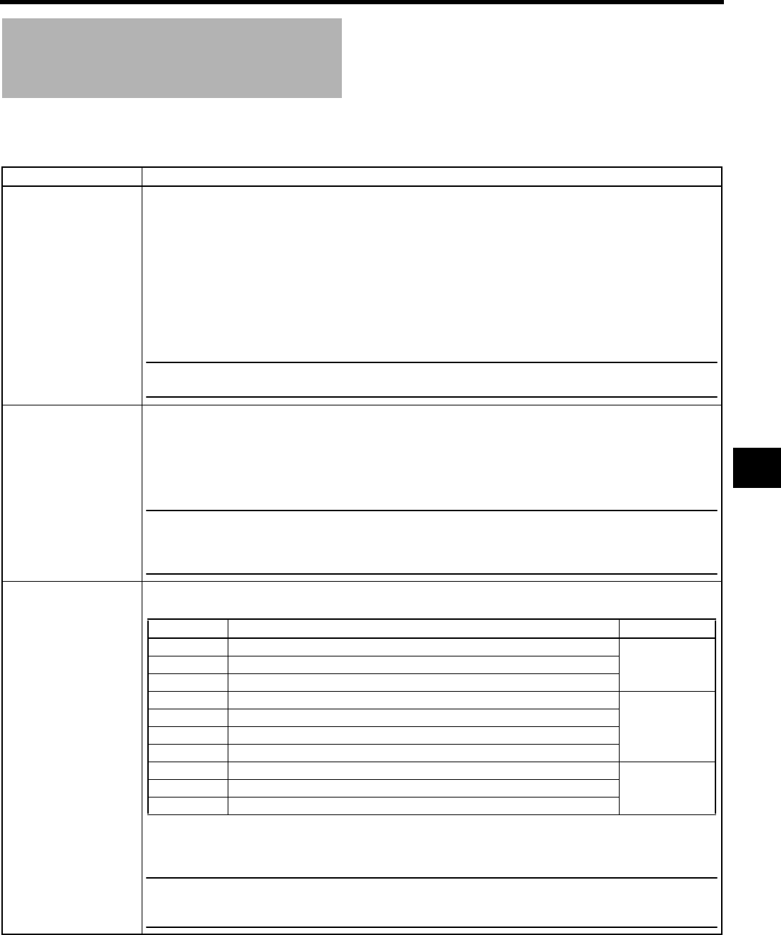
77
VIDEO FORMAT[1/2] Menu
Screen
The VIDEO FORMAT menu screen consists of two screens (1/2 screen, 2/2 screen).
In VTR mode, this screen consists of one screen.
* This is not displayed in VTR mode.
Item Function/Setting (bold characters indicate initial settings)
FRAME RATE Sets the frame rate for shooting.
U model
60/30 : Shoots at 480/60i, 720/60p, 720/30p.
50/25 : Shoots at 720/50p, 720/25p.
24 : Shoots at 480/24p (2:3:2:3 pulldown), 480/24p advance mode (2:3:3:2 pulldown), 720/24p.
E model
60/30 : Shoots at 720/60p, 720/30p.
50/25 : Shoots at 576/50i, 720/50p, 576/25p, 720/25p.
24 : Shoots at 720/24p.
CANCEL : Cancels the settings.
EXECUTE : Executes the settings.
MEMO
• If you change the FRAME RATE item setting, the system is rebooted. XSee page 54.
• The cursor (K) does not move to this item when this device is in VTR mode or is ejecting a tape.
1080I CAMERA* Selects whether or not to output camera images in HDV1080i signals. HDV1080i signals are output from component
output of the Y/PB/PR terminal or HD/SD-SDI output terminal. However, they are not recorded on this device.
OFF : No HDV1080i signal is output. Output setting of camera images is based on the REC settings below.
ON : HDV1080i signal is output. (60/30 Frame rate: 1080/60i, 50/25 Frame rate: 1080/50i)
480/60i or 576/50i signals are output from the VIDEO OUT terminal.
• ON/OFF is set when the SHUTTER dial is pressed.
MEMO
• Tape recording and IEEE1394 output are not available when this is ON.
• REC item cannot be set when this is ON.
• The cursor is positioned on 1080I CAMERA in the VIDEO FORMAT[1/2] menu screen when this is ON.
• When the FRAME RATE is set to 24, this is fixed to OFF.
REC* Sets the video format for shooting. (Can only be displayed and set in camera mode)
You can set the following according to the FRAME RATE.
CANCEL : Cancels the settings.
EXECUTE : Executes the settings.
MEMO
• The synchronous video signal is momentarily disturbed when the REC item setting is switched.
• On the E model, the video format is fixed at HDV-HD24P when the FRAME RATE item is set to “24”. “[HDV-
HD24P]” is displayed.
Setting Description FRAME RATE
DV-60I DV format Shoots using a 480/60i signal. (U model Only)
60/30HDV-HD60P HDV format Shoots using a 720/60p signal.
HDV-HD30P HDV format Shoots using a 720/30p signal.
HDV-HD50P HDV format Shoots using a 720/50p signal.
50/25
HDV-HD25P HDV format Shoots using a 720/25p signal.
DV-50I DV format Shoots using a 576/50i signal. (E model Only)
DV-25P DV format Shoots using a 576/25p signal. (E model Only)
DV-24P DV format Shoots at 480/24p (2:3:2:3 pulldown). (U model Only)
24DV-24PA DV format Shoots at 480/24p (2:3:3:2 pulldown). (U model Only)
HDV-HD24P HDV format Shoots using a 720/24p signal.
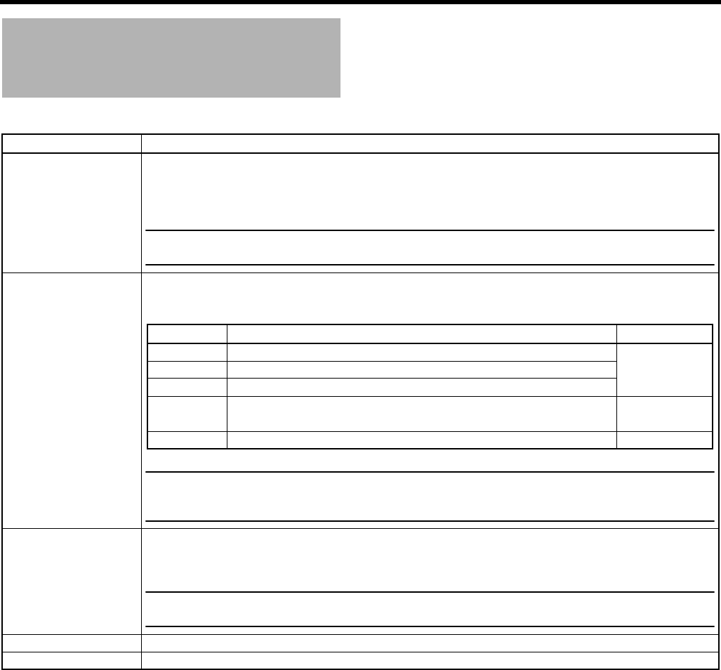
MENU SCREENS
78
VIDEO FORMAT[1/2] Menu Screen
(Cont’d)
* This is not displayed in VTR mode.
Item Function/Setting (bold characters indicate initial settings)
ASPECT* Sets the screen size for the recording video signal. (Can only be displayed and set in camera mode)
4:3 : Outputs the video with an aspect ratio of 4:3.
16:9 : Outputs the video with an aspect ratio of 16:9.
The resolution in the vertical direction drops compared to 4:3 video.
MEMO
• When the format setting is HDV, the ASPECT item is fixed at 16:9. (“[16:9]” is displayed.)
• The synchronous video signal is momentarily disturbed when the ASPECT item setting is switched.
HDV PB OUTPUT When playing back an HDV recorded tape, set video format for component output from the Y/PB/PR terminal or SDI
output from the HD/SD-SDI output terminal.
You can set the following depending on the FRAME RATE of the HDV recorded tape.
MEMO
• If you convert video recorded in HDV format to DV format and output it, the colors may change.
• This item is also applied to EE images when HDV signals are input to the IEEE1394 terminal.
• Fixed at NATIVE during DV recorded tape playback or DV signal input.
DOWN CON. [HDV] Set the style to display down-converted images in aspect ratio 4:3.
SQUEEZE : Image that is squeezed horizontally is displayed.
LETTER : Wide image with the top and bottom blackened is displayed.
MEMO
This setting is only valid in HDV mode.
In DV mode, the style becomes SQUEEZE regardless of the setting of this item.
NEXT PAGE To display the VIDEO FORMAT[2/2] menu screen, move the cursor to this position and press the SHUTTER dial.
PAGE BACK The TOP MENU returns when the SHUTTER dial is pressed with the cursor at this position.
Setting Description FRAME RATE
NATIVE Outputs the signal being recorded on the tape. 60/30
720P Converts the signal being recorded on tape to 720p and outputs it. 50/25
1080I Converts the signal being recorded on tape to 1080i and outputs it. 24
NTSC Converts the signal being recorded on tape to 480i and outputs it. 60/30
24
PAL Converts the signal being recorded on tape to 576i and outputs it. 50/25
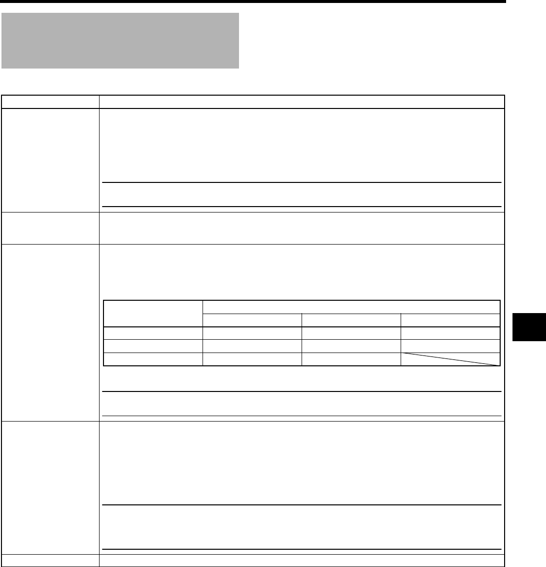
79
VIDEO FORMAT[2/2] Menu
Screen
* This is not displayed in VTR mode.
Item Function/Setting (bold characters indicate initial settings)
PB TAPE Selects whether to automatically detect the playback tape video format or play back only a particular format.
Normally, use the “AUTO” setting.
AUTO : During tape playback, the format signal is switched automatically and played back.
DV : During tape playback, only the part of the tape recorded in DV format is played back.
HDV : During tape playback, only the part of the tape recorded in HDV format is played back.
DVCAM : During tape playback, only the part of the tape recorded in DVCAM format is played back.
MEMO
If you play back a tape containing both DV and HDV formats, the video signal is disturbed when the signal is
switched.
HD/SD-SDI OUT Sets whether or not to output SDI (Serial Digital Interface) signals from the HD/SD SDI OUT terminal.
OFF : No output.
ON : Output on. Embedded audio and time code are also output.
OUTPUT TERM. [DV] Sets the output image format for the Y/PB/PR terminal in DV format.
Y/Pb/Pr: Outputs analog component signals.
R/G/B : Outputs analog RGB signals.
Y/C : Outputs YC separate signals.
Signals are output from terminals as shown in the table below depending on the settings.
(When the [PBPR/TC] switch is set to PBPR)
MEMO
• SYNC signals are added to all channels for RGB signals.
• In HDV format, signals are output in analog component format regardless of these settings.
SET UP Selects whether to add a setup signal to the video signal output from the video signal output connector.
In DV format, a setup signal can be added to COMPONENT output and Y/C output.
(When Y/PB/PR or Y/C is set for OUTPUT TERM [DV])
* You can also select a setup signal in the IEEE1394 signal input mode.
0.0% : No setup signal is added.
7.5% : A setup signal is added.
Initial settings: U model: 7.5% E model: 0.0%
MEMO
• When recording composite video signals from an external device, set this item according to whether the input
signals include a setup signal.
XSee “Recording Composite Video Signals from an External Device” on page 65.
• When the FRAME RATE item is set to 50/25, this item is not displayed.
PAGE BACK When the cursor is in this position, press the SHUTTER dial to the VIDEO FORMAT[1/2] menu screen.
Terminal Setting
Y/Pb/PrR/G/B Y/C
Y Component Y G Y
PBComponent PBBC
PRComponent PRR

MENU SCREENS
80
CAMERA OPERATION
Menu Screen
The CAMERA OPERATION menu screen is only displayed in the Camera mode.
*1 REMOTE appears as the setting value of this item when the remote control unit is connected.
Item Function/Setting (bold characters indicate initial settings)
AE LEVEL*1 For adjusting the image level when using auto iris, “ALC” or “EEI”.
Increase value : Increases level.
Decrease value : Decreases level.
[Settings: –3, –2 - NORMAL (0) - 2, 3]
ALC MAX Sets the maximum “ALC” value to automatically change the signal intensity level depending on the brightness.
[Setting: 6 dB, 12 dB, 18 dB]
PRESET TEMP. Sets the basic color temperature when the [WHT.BAL] white balance selector switch c on page 15 is in the PRST
(PRESET) position.
3200K : Sets the basic color temperature to 3200K. (Use for light sources with a low color temperature,
such as halogen lamps.)
5600K : Sets the basic color temperature to 5600K. (Use for light sources with a high color temperature,
such as sunlight.)
MEMO
This item does not function when the FAW item on the SWITCH MODE menu screen is set to “PRESET”.
SMOOTH TRANS*1 Smoothens the transition when the [GAIN] switch b on page 15, or [WHT.BAL] switch c on page 15 is switched
over and achieves gradual change in place of sudden change.
However, the smooth transition function does not function when switching the [GAIN] switch set in ALC, FULL AUTO
ON.
OFF : Deactivates the smooth transition function.
ON : Activates the smooth transition function.
BARS*1 Sets whether or not color bars are output. (This is fixed at “OFF” when in FULL AUTO mode)
OFF : Color bars are not output.
ON : Color bars are output.
PAGE BACK The TOP MENU returns when the SHUTTER dial is pressed with the cursor at this position.

81
CAMERA PROCESS[1/2]
Menu Screen
The CAMERA PROCESS menu screen consists of two screens. (1/2 screen, 2/2 screen)
The CAMERA PROCESS menu screen is only displayed in camera mode.
*1 When the REC item on the VIDEO FORMAT[1/2] menu is set to “DV-60I” or “DV-50I”, “-----” is displayed and this cannot be
selected.
*2 REMOTE appears as the setting value of this item when the remote control unit is connected.
Item Function/Setting (bold characters indicate initial settings)
MASTER BLACK*2 Adjusts the pedestal level (master black) that serves as the reference black.
Increase the number : Raises the pedestal level.
Decrease the number : Lowers the pedestal level.
[Settings: MIN (–10), –9 - NORMAL (0) - 9, MAX (10)]
DETAIL*2 Adjusts the contour (detail) sharpness level.
Increase the number : Sharpens the contour.
Decrease the number : Softens the contour.
OFF : Does not function.
[Settings: OFF, MIN (–10), –9 - NORMAL (0) - 9, MAX (10)]
When this item is set to “OFF”, “-----” is displayed for the following menu items and they cannot be selected.
V/H BALANCE*2 Sets which contours (details) to sharpen, those in the horizontal (H) direction or those in the vertical (V) direction.
Increase the number : Sharpens H direction.
Decrease the number : Sharpens V direction.
[Settings: H-MIN (–5), –4 - NORMAL (0) - 4, H-MAX (5)]
H FREQUENCY*2 Changes the horizontal contour compensation frequency for the contours (details). Set this as appropriate for the
subject.
LOW : Enhances low frequency bands.
Use this when shooting subjects with large patterns.
MIDDLE : Enhances middle frequency bands.
HIGH : Enhances high frequency bands.
Use this when shooting subjects with small patterns.
V FREQUENCY*1 Use this when shooting subjects with finely detailed patterns.
Changes the vertical contour compensation frequency for the contours (details). Compensates for distortion when
outputting progressive video to an interlaced monitor.
HIGH : Enhances high frequency bands.
LOW : Enhances low frequency bands.
SKIN DETECT*2 Sets ON/OFF for the skin detail function.
OFF : Turns off the skin detail function.
ON : Turns on the skin detail function. (Softens detected skin color area details.)
XSee “Using the Skin Detail Function” on page 104.
LEVEL Sets the contour compensation level (amount of softening) for the skin detail function.
This can only be selected when the SKIN DETECT item is set to ON.
–1 : Low contour compensation level (amount of softening)
–2 : Medium contour compensation level (amount of softening)
–3 : High contour compensation level (amount of softening)
NEXT PAGE To display the CAMERA PROCESS[2/2] menu screen, move the cursor to this position and press the SHUTTER dial.
PAGE BACK The TOP MENU returns when the SHUTTER dial is pressed while the cursor is at this position.
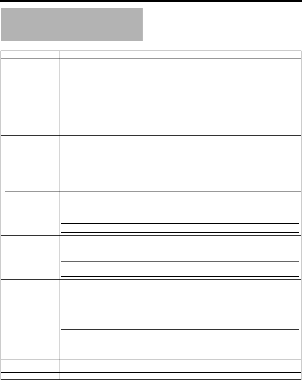
MENU SCREENS
82
CAMERA PROCESS[2/2]
Menu Screen
*1 REMOTE appears as the setting value of this item when the remote control unit is connected.
Item Function/Setting (bold characters indicate initial settings)
BLACK*1 Changes the gain in dark areas. Change this depending on the video signal being shot.
STRETCH LEVEL The amount of stretching increases from LEVEL1→LEVEL2→LEVEL3→LEVEL4→LEVEL5.
[Settings: LEVEL1, LEVEL2, LEVEL3, LEVEL4, LEVEL5]
COMPRESS LEVEL The amount of compression increases from LEVEL1→LEVEL2→LEVEL3→LEVEL4→LEVEL5.
[Settings: LEVEL1, LEVEL2, LEVEL3, LEVEL4, LEVEL5]
WHITE CLIP Sets the white clipping point on input video signals with a high luminance level.
108% : The white clipping point is set at a luminance level of 108%.
100% : The white clipping point is set at a luminance level of 100%. If the screen is too white at
108%, set it to 100%.
KNEE*1 Sets whether to run the “knee” function, which compresses video signals over a certain level to render the tonality
in the highlight areas, automatically or manually. Set “MANUAL” when you want to check the bright areas, and adjust
the knee point manually.
AUTO : Adjusts the knee point automatically, according to the luminance level.
MANUAL : You can change the luminance level in the “LEVEL” item.
LEVEL*1 Sets the start point for knee compression (knee point).
Increase the number : Raises the knee point level.
Decrease the number : Lowers the knee point level.
[Settings: 80%, 85%, 90%, 95%, 100%]
MEMO
When the “KNEE” item is set to “AUTO”, “-----” is displayed and this cannot be selected.
REVERSE PICTURE When the lens image is inverted and flipped, set “ROTATE” to record properly.
OFF : No inversion.
ROTATE : Invert lens image.
MEMO
When the REVERSE PICTURE item is set to ROTATE, skin detail function is available but the detection area is
not displayed in the viewfinder or LCD screen.
DNR Selects whether or not to set the noise reduction.
The DNR (Digital Noise Reduction) function is applied to the tape recording signal, HD component output signal, and
the IEEE1394 output signal in CAMERA mode.
When camcorder’s picture is noisy, because of low light conditions, you can improve picture’s S/N by turning DNR
on.
OFF : Noise reduction is not performed.
ON : Sets noise reduction.
MEMO
• DNR is not applied in VTR mode, AUX IN mode or during playback.
• DNR is not applied to composite output signals in CAMERA mode.
• When the DNR is set to ON, the camcorder’s S/N ratio becomes better but the “blurring of moving objects” will
increase.
ADVANCED PROCESS.. Calls up the ADVANCED PROCESS menu screen.
XSee “ADVANCED PROCESS Menu Screen” on page 83.
PAGE BACK When the cursor is in this position, press the SHUTTER dial to return to the CAMERA PROCESS[1/2] menu screen.
NORMAL : Normal status
STRETCH : Enhances the dark areas of the video so the contrast between light and dark is more visible by
stretching the signal only in the dark areas.
Set elongation level with STRETCH LEVEL below.
COMPRESS : If the video that was shot is bright overall and lacking in contrast, the gain in the dark areas is com-
pressed, which adds contrast.
Set compression level with COMPRESS LEVEL below.
83
ADVANCED PROCESS
Menu Screen
Item Function/Setting (bold characters indicate initial settings)
CINEMA OFF : Turns the function OFF.
ON : Sets the gamma characteristics and color matrix close to the characteristics of a movie
screen. (The monitor image is movie-quality. This setting is not intended for film output.)
MEMO
When this item is set to “ON”, “[CINE]” is displayed for COLOR MATRIX and GAMMA items and cannot be
selected.
COLOR MATRIX Sets the color matrix.
OFF : Turns the function OFF.
STANDARD : Sets a normal color matrix.
CINEMA : Sets a color matrix close to the characteristics of a movie screen.
ADJUST.. When “STANDARD” or “CINEMA” is set for the COLOR MATRIX item, a color matrix can be set individually.
Press the SHUTTER dial to call up the COLOR MATRIX ADJUST menu screen.
XSee “COLOR MATRIX ADJUST Menu Screen” on page 84.
GAMMA Adjusts the gamma curve to determine how black is rendered.
OFF : No gamma curve correction.
STANDARD : Sets a normal gamma curve.
CINEMA : Sets to appear movie-like when viewing on a TV screen.
FILM OUT : Sets to a setting for recording onto film.
MEMO
When this item is set to “OFF”, “-----” is displayed for the LEVEL item and it cannot be selected.
LEVEL When “STANDARD”, “CINEMA”, or “FILM OUT” is set for the GAMMA item, a gamma curve can be set individually.
Increase the number : Enhances the tonality of the black. However, the tonality in the bright areas deteriorates.
Decrease the number : Enhances the tonality in the bright areas. However, the tonality in the black areas deterio-
rates.
[Settings: MIN (–5), –4 - NORMAL (0) - 4, MAX (5)]
COLOR GAIN Adjusts the video signal color level.
OFF : Sets the video to black and white.
Increase the number : Makes the colors more dense.
Decrease the number : Makes the colors less dense.
[Settings: OFF, MIN (–10), –9 - NORMAL (0) - 9, MAX (10)]
WHITE BALANCE.. When the cursor is in this position and you press the SHUTTER dial once, the screen switches to the WHITE BAL-
ANCE menu screen.
SKIN COLOR ADJUST.. When the cursor is in this position and you press the SHUTTER dial once, the screen switches to the SKIN COLOR
ADJUST screen.
PAGE BACK When the cursor is in this position, press the SHUTTER dial to return to the CAMERA PROCESS[2/2] menu screen.
MENU SCREENS
84
COLOR MATRIX ADJUST
Menu Screen
SKIN COLOR ADJUST
Menu Screen
When you enter the SKIN COLOR ADJUST screen, the areas where the skin detail function is applied are displayed in color, and
other areas are displayed in black and white.
Item Function/Setting (bold characters indicate initial settings)
R GAIN For manually adjusting the shading of the R axis of the color matrix (red and cyan).
Increase the number : Enhances red and cyan.
Decrease the number : Reduces red and cyan.
[Settings: MIN (–5), –4 - NORMAL (0) - 4, MAX (5)]
R ROTATION For manually adjusting the color phase of the R axis of the color matrix (red and cyan).
Increase the number : Increases yellowishness of red color and bluishness of cyan color.
Decrease the number : Increases bluishness of red color and greenishness of cyan color.
[Settings: MIN (–5), –4 - NORMAL (0) - 4, MAX (5)]
G GAIN For manually adjusting the shading of the G axis of the color matrix (green and magenta).
Increase the number : Enhances green and magenta.
Decrease the number : Reduces green and magenta.
[Settings: MIN (–5), –4 - NORMAL (0) - 4, MAX (5)]
G ROTATION For manually adjusting the color phase of the G axis of the color matrix (green and magenta).
Increase the number : Increases bluishness of green color and reddishness of magenta color.
Decrease the number : Increases yellowishness of green color and bluishness of magenta color.
[Settings: MIN (–5), –4 - NORMAL (0) - 4, MAX (5)]
B GAIN For manually adjusting the shading of the B axis of the color matrix (blue and yellow).
Increase the number : Enhances blue and yellow.
Decrease the number : Reduces blue and yellow.
[Settings: MIN (–5), –4 - NORMAL (0) - 4, MAX (5)]
B ROTATION For manually adjusting the color phase of the B axis of the color matrix (blue and yellow).
Increase the number : Increases reddishness of blue color and greenishness of yellow color.
Decrease the number : Increases greenishness of blue color and reddishness of yellow color.
[Settings: MIN (–5), –4 - NORMAL (0) - 4, MAX (5)]
PAGE BACK Press the SHUTTER dial to return to the ADVANCED PROCESS screen when cursor is at this position.
Item Function/Setting (bold characters indicate initial settings)
SKIN COLOR DET. Sets the color used by the skin detail function.
STOP : Stops loading the color used by the skin detail function.
EXECUTE : Loads the color used by the skin detail function.
XSee “How to Use Skin Detail” on page 103.
SKIN COLOR RANGE Adjusts the range of skin colors to which the skin detail function is applied.
Adjust as you check the color range.
Increase the number : Widens the range.
Decrease the number : Narrows the range.
[Settings: NARROW (–10), –9 - NORMAL (0) - 9, WIDE (10)]
MEMO
When the COLOR GAIN item is “OFF” on the ADVANCED PROCESS menu screen, only the areas where the
skin detail function is running are displayed using skin colors.
PAGE BACK When the cursor is in this position, press the SHUTTER dial to return to the ADVANCED PROCESS menu screen.
85
WHITE BALANCE Menu
Screen
*1 REMOTE appears as the setting value of this item when the remote control unit is connected.
Item Function/Setting (bold characters indicate initial settings)
WHITE PAINT<R>*1 Adjusts the R (red) component when in AWB (Auto White Balance) mode.
Increase the number : Strengthens the red.
Decrease the number : Weakens the red.
[Settings: MIN (–32), –31 - NORMAL (0) - 30, MAX (31)]
MEMO
• You can select this when A or B is set for the [WHT.BAL] switch c on the right panel of this device.
XSee page 15.
Settings can be made for A and B individually. (When “PRESET” is set, “-----” is displayed and this cannot be
selected.)
• When you press the AWB (Auto White Balance) button and readjust the white balance, WHITE PAINT R
becomes “NORMAL”.
WHITE PAINT<B>*1 Adjusts the B (blue) component when in AWB (Auto White Balance) mode.
Increase the number : Strengthens the blue.
Decrease the number : Weakens the blue.
[Settings: MIN (–32), –31 - NORMAL (0) - 30, MAX (31)]
MEMO
• You can select this when A or B is set for the [WHT.BAL] switch c on the right panel of this device.
XSee page 15.
Settings can be made for A and B individually. (When “PRESET” is set, “-----” is displayed and this cannot be
selected.)
• When you press the AWB (Auto White Balance) button and readjust the white balance, WHITE PAINT <B>
becomes “NORMAL”.
SHADING Adjusts white shading.
PRESET : No white shading adjustment.
MANUAL : Enables white shading adjustment.
XSee “White Shading Adjustment” on page 53.
MEMO
When the SHADING item is set to PRESET, the LEVEL R, LEVEL G, and LEVEL B items cannot be selected.
LEVEL R When the SHADING item is set to MANUAL, adjusts the reds of white shading.
Increase the number : Red at the bottom of the screen is suppressed and the top is enhanced.
Decrease the number : Red at the top of the screen is suppressed and the bottom is enhanced.
[Settings: MIN, –127 to –1, NORMAL, 1 to 126, MAX]
LEVEL G When the SHADING item is set to MANUAL, adjusts the greens of white shading.
Increase the number : Green at the bottom of the screen is suppressed and the top is enhanced.
Decrease the number : Green at the top of the screen is suppressed and the bottom is enhanced.
[Settings: MIN, –127 to –1, NORMAL, 1 to 126, MAX]
LEVEL B When the SHADING item is set to MANUAL, adjusts the blues of white shading.
Increase the number : Blue at the bottom of the screen is suppressed and the top is enhanced.
Decrease the number : Blue at the top of the screen is suppressed and the bottom is enhanced.
[Settings: MIN, –127 to –1, NORMAL, 1 to 126, MAX]
PAGE BACK When the cursor is in this position, press the SHUTTER dial to return to ADVANCED PROCESS menu screen.
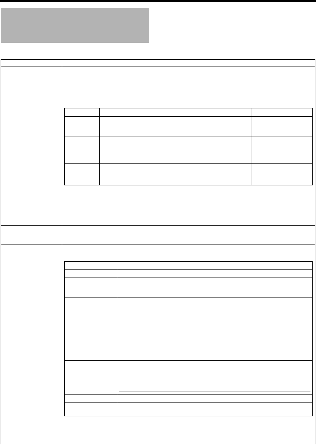
MENU SCREENS
86
SWITCH MODE Menu
Screen
The SWITCH MODE menu screen is only displayed in camera mode.
Item Function/Setting (bold characters indicate initial settings)
SHUTTER Sets the fixed value (STEP) for values that can change using the SHUTTER dial on the right panel or the VARIABLE
used when shooting computer monitors.
STEP : Switches the shutter speed using fixed values.
VARIABLE : Set when shooting a computer monitor, etc.
You can set the following using the REC item on the VIDEO FORMAT menu screen. (This is fixed at EEI when in
FULL AUTO mode.)
FAW Sets the positions to assign the FAW (Full Auto White Balance) function to the [WHT.BAL] white balance selector
switch c on page 15. (Fixed at FAW when in FULL AUTO mode)
NONE : The FAW function is not assigned.
A : Assigns FAW to the A position.
B : Assigns FAW to the B position.
PRESET : Assigns FAW to the PRESET position.
GAIN L
GAIN M
GAIN H
Sets the gain value for each position on the [GAIN] sensitivity selector switch b on page 15.
[Setting: 0dB, 3dB, 6dB, 9dB, 12dB, 15dB, 18dB, ALC] (Fixed at ALC in FULL AUTO mode)
Initial values: L: 0dB, M: 9dB, H: 18dB
USER1
USER2
USER3
You can assign one of the following menu functions to the [USER1/2/3] buttons
8
on page 14 to each button.
Set according to the shooting conditions. This is only valid in CAMERA mode.This does not function in VTR mode.
LENS RET Sets the lens RET button functions. (This does not function if there is not RET button on the lens you are using.)
RET : Functions as a normal RET button.
FOCUS ASSIST : Functions as the FOCUS ASSIST button.
PAGE BACK When the cursor is in this position, press the SHUTTER dial to return to the TOP MENU screen.
REC Item Setting for STEP Setting for VARIABLE
DV-60I
HDV-HD60P
HDV-HD30P
1/7.5, 1/15, 1/30, 1/60, 1/100, 1/250, 1/500, 1/1000, 1/2000, 1/4000,
1/10000
1/30.03 - 1/10489.5
DV-50I
HDV-HD50P
HDV-HD25P
1/6.25, 1/12.5, 1/25, 1/50, 1/120, 1/250, 1/500, 1/1000, 1/2000,
1/4000, 1/10000
1/25.04 - 1/10489.5
DV-25P
DV-24P
DV-24PA
1/6, 1/12, 1/24, 1/48, 1/60, 1/100, 1/250, 1/500, 1/1000, 1/2000,
1/4000, 1/10000
1/24.01 - 1/10489.5
HDV-HD24P
Setting Description
NONE Does not function.
BARS
PRESET TEMP.
Assigns “BARS” item functions in the CAMERA OPERATION menu screen.
Assigns “PRESET TEMP.” item functions in the CAMERA OPERATION menu screen.
XSee “CAMERA OPERATION Menu Screen” on page 80.
B.STRETCH1
B.STRETCH2
B.STRETCH3
B.STRETCH4
B.STRETCH5
B.COMPRESS1
B.COMPRESS2
B.COMPRESS3
B.COMPRESS4
B.COMPRESS5
Assigns “BLACK” item functions in the CAMERA PROCESS[1/2] menu screen.
XSee “CAMERA PROCESS[1/2] Menu Screen” on page 81.
AE LEVEL+
AE LEVEL–
Assigns “AE LEVEL” item functions in the CAMERA OPERATION menu screen.
MEMO
Cannot assign to the USER3 button. If you assign these menu functions, assign AE
LEVEL+ to the USER1 button, AE LEVEL– to the USER2 button.
RET Assigns the normal RET button function.
LOAD FILE Assigns the function to jump to in the LOAD FILE menu.
XSee “FILE MANAGE Menu Screen” on page 100.

87
AUDIO/MIC[1/2] Menu
Screen
The AUDIO/MIC menu screen consists of two screens (1/2 screen, 2/2 screen).
In VTR mode, the screen changes to the AUDIO menu screen.
* This is not displayed in VTR mode.
Item Function/Setting (bold characters indicate initial settings)
TEST TONE Sets whether to output a test audio signal (1 kHz, –20dBFS or –12dBFS) during color bar output.
OFF : A test audio signal is not output.
ON : A test audio signal is output.
MIC WIND CUT* Selects whether to cut the lows (low frequency bands) from the audio input signal.
Use this when you want to reduce wind sounds from the microphone.
OFF : Low frequencies are not cut.
INPUT1 : Only cuts the low frequencies in the audio from the INPUT1 connector.
INPUT2 : Only cuts the low frequencies in the audio from the INPUT2 connector.
BOTH : Cuts the low frequencies in the audio from both the INPUT1 and INPUT2 terminals.
AUDIO REF.LEVEL Sets the reference audio level on the tape. (Both CH-1 and CH-2)
–20dB : Records with –20 dB as the reference audio level.
–12dB : Records with –12 dB as the reference audio level.
Set this if you are playing back the recorded tape on an ordinary DV device.
* Set this for both playback and recording.
* This is unrelated to the audio level via the IEEE1394 signal.
INPUT1 MIC REF.* Sets the reference audio input level for the INPUT1 connector. (When the [AUDIO INPUT] switch 3 on page 16 is
set to MIC or MIC+48)
–50dB : Sets the reference audio input level at –50 dB.
–60dB : Sets the reference audio input level at –60 dB.
INPUT2 MIC REF.* Sets the reference audio input level for the INPUT2 connector. (When the [AUDIO INPUT] switch 3 on page 16 is
set to MIC or MIC+48)
–50dB : Sets the reference audio input level at –50 dB.
–60dB : Sets the reference audio input level at –60 dB.
AUDIO MODE* Selects the audio sampling frequency for recording. (Both CH-1 and CH-2)
(When HDV format is set, this is fixed at 48K and “[48K]” is displayed.)
32K : Digitally records with a 12-bit, 32 kHz sampling frequency.
48K : Digitally records with a 16-bit, 48 kHz sampling frequency.
* If the DV format is 12-bit, 32 kHz, up to 4 recording track channels are available.
Of those, GY-HD250/GY-HD251 records on the CH-1 and CH-2 channels. GY-HD250/GY-HD251 is not capable of
dubbing.
AUDIO LIMITER* Sets whether or not AUDIO LIMITER functions when the [CH-1/CH-2 AUDIO SELECT] switch 2 on page 13 is set
to MANU.
OFF : AUDIO LIMITER is turned off.
ON : AUDIO LIMITER is turned on. Recording level is suppressed when excessive audio is input.
NEXT PAGE To display the AUDIO/MIC[2/2] menu screen, move the cursor to this position and press the SHUTTER dial.
PAGE BACK When the cursor is in this position, press the SHUTTER dial to return to the TOP MENU screen.

MENU SCREENS
88
AUDIO/MIC[2/2] Menu
Screen
In VTR mode, the screen changes to the AUDIO menu screen.
* This is not displayed in VTR mode.
Item Function/Setting (bold characters indicate initial settings)
AUDIO MONITOR Selects whether stereo or mixed audio is output from the PHONES jack when the MONITOR SELECT switch is set
to BOTH.
STEREO : Stereo audio (CH-1 audio is output to L and CH-2 audio is output to R)
* Outputs only the CH-1 audio from the monitor speaker.
MIX : Mixed audio (CH-1 and CH-2 mixed audio is output to L and R)
FAS AUDIO* Selects the recording level adjusting method for FAS (Full Auto Shooting). (CH-1, CH-2)
AUTO :Sets to AUTO.
SW SET : Follows settings for the AUDIO SELECT switch.
XSee “2 [CH-1/CH-2 AUDIO SELECT] switch” on page 13.
XSee “g [FULL AUTO] switch” on page 19.
SEARCH AUDIO [DV] Selects whether to output audio when searching a tape recorded in DV format. (This also includes slow playback.)
ON : Audio is output.
OFF : Audio is not output.
PB AUDIO CH [DV] Selects which channel audio to output when playing back a DV tape with the audio signal recorded in 4 channels.
(Can only be set in VTR mode)
CH1/2 : Outputs the CH-1 and CH-2 channel audio.
GY-HD250/GY-HD251 records the audio in CH-1 and CH-2 while shooting.
MIX : Outputs all 4 channels of audio at the same time.
CH3/4 : Outputs the CH-3 and CH-4 channel audio.
MEMO
GY-HD250/GY-HD251 does not have a function for dubbing to the CH-3 and CH-4 channels.
PAGE BACK When the cursor is in this position, press the SHUTTER dial to the AUDIO/MIC[1/2] menu screen.
89
LCD/VF[1/4] Menu Screen
The LCD/VF menu screen consists of four screens. (1/4 screen, 2/4 screen, 3/4 screen, 4/4 screen)
The LCD/VF[1/4] menu screen can only be set in camera mode.
In VTR mode, this screen consists of two screens. (1/2 screen, 2/2 screen)
*1 SAFETY ZONE and CENTER MARK will not be displayed when this device is in VTR mode (PLAY, STL, FWD, REV).
Item Function/Setting (bold characters indicate initial settings)
ZEBRA Switches the luminance level of the subject sections where the zebra pattern is displayed.
60-70% : Zebra pattern is displayed in sections with luminance levels between 60% and 70%.
70-80% : Zebra pattern is displayed in sections with luminance levels between 70% and 80%.
85-95% : Zebra pattern is displayed in sections with luminance levels between 85% and 95%.
OVER95% : Zebra pattern is displayed in sections with luminance levels over 95%.
OVER100% : Zebra pattern is displayed in sections with luminance levels over 100%.
F. NO/IRIS IND. Selects whether or not the F-number of the lens iris/iris level mark is displayed in the status display on the LCD mon-
itor or in the viewfinder. (STATUS 1 screen)
OFF : F-number and iris level mark is not displayed.
F.NO : F-number is displayed.
F.NO+IND. : F-number and iris level mark is displayed.
FILTER Selects whether or not the FILTER position of this device is displayed in the status display on the LCD monitor or in
the viewfinder. (STATUS 1 screen)
OFF : FILTER position is not displayed.
ON : FILTER position is displayed.
SAFETY ZONE*1 Selects whether or not the safety zone is shown on the LCD monitor or in the viewfinder together with the form of
the safety zone indication.
OFF : Not displayed.
4:3 : 4:3 zone is displayed.
14:9 : 14:9 zone is displayed.
16:9 : 16:9 zone is displayed.
16:9+4:3 : 16:9 zone and 4:3 zone are display mixed. (This cannot be selected when DV format is set.)
2.35:1 CE : Displays 2.35:1 zone in the middle of the screen.
(Only in HDV format or 24P or 25P mode)
2.35:1 CH : Displays 2.35:1 zone at the top of the screen.
(Only in HDV format or 24P or 25P mode)
CENTER MARK*1 Sets whether or not a center mark is displayed when the safety zone is displayed.
ON : Center mark is displayed.
OFF : Center mark is not displayed.
MEMO
When the SAFETY ZONE item is set to OFF, “- - -” is indicated and this item cannot be selected.
FOCUS ASSIST Sets the FOCUS ASSIST function. Press the [FOCUS ASSIST] button on page 14 (6) or page 18 (7) to operate
the FOCUS ASSIST function.
NORMAL : Only the [FOCUS ASSIST] function operates.
(The focus area becomes blue, red or green, making it easier to focus.)
ACCU-FOCUS : The FOCUS ASSIST function and ACCU-FOCUS (forced focus) function operates.
This makes the depth of field shallower, making it easier to focus. ACCU FOCUS automatically
turns OFF after approximately 10 seconds.
COLOR Sets the display color for focusing when running the FOCUS ASSIST function.
BLUE : Displays the area of focus in blue.
RED : Displays the area of focus in red.
GREEN : Displays the area of focus in green.
LEVEL Sets the display range of the focal area when the FOCUS ASSIST function is in use.
LOW : Displays the focal area narrower than MIDDLE.
MIDDLE : Displays the focal area in normal setting.
HIGH : Displays the focal area wider than MIDDLE.
NEXT PAGE When you display the LCD/VF[2/4] menu screen, move the cursor to this position and press the SHUTTER dial.
PAGE BACK When the cursor is in this position, press the SHUTTER dial to return to the TOP MENU screen.

MENU SCREENS
90
LCD/VF[2/4] Menu Screen
The LCD/VF[2/4] menu screen can only be set in camera mode.
Item Function/Setting (bold characters indicate initial settings)
LCD MIRROR MODE Sets the image display method when the LCD monitor is in counterview position.
NORMAL : Image is displayed without inverting.
MIRROR : Inverted image is displayed.
• NORMAL/MIRROR is set when the SHUTTER dial is pressed.
MEMO
MIRROR setting is disabled when color bar is displayed or status is in magnified size.
XSee “Outputting Color Bars” on page 105.
XSee “Magnified Status Indications on the LCD Monitor” on page 29.
NEXT PAGE When you display the LCD/VF[3/4] menu screen, move the cursor to this position and press the SHUTTER dial.
PAGE BACK When the cursor is in this position, press the SHUTTER dial to return to the LCD/VF[1/4] menu screen.
91
LCD/VF[3/4] Menu Screen
[1/2] screen is displayed in the VTR mode.
Item Function/Setting (bold characters indicate initial settings)
VIDEO FORMAT Selects whether to display the video format in the status display on the LCD monitor or the viewfinder.
(Camera mode: STATUS 1 screen, VTR mode: STATUS screen)
ON : Displays the video format.
OFF : Does not display the video format.
In camera mode : Displays the video format set in the REC item on the VIDEO FORMAT menu screen.
In VTR mode : Displays the video format recorded on the playback tape or the video format input from the
IEEE1394 connector.
TAPE REMAIN Selects whether or not the remaining tape time (minutes) is shown in the status display on the LCD monitor or in the
viewfinder.
(Camera mode: STATUS 1 screen, VTR mode: STATUS screen)
ON : Displayed.
OFF : Not displayed.
TC/UB Selects whether or not the time code or user’s bits data should be shown in the status display on the LCD monitor
or in the viewfinder.
(Camera mode: STATUS 1 screen, VTR mode: STATUS screen)
ON : Displayed.
OFF : Not displayed.
* Whether the time code or user’s bits data is shown is selected with the TC DISPLAY switch.
AUDIO Selects whether the audio level meters should be shown in the status display on the LCD monitor and the viewfinder
screen.
(Camera mode: STATUS 1 screen, VTR mode: STATUS screen)
ON : Displayed.
OFF : Not displayed.
BATTERY INFO. For setting the status display method when loading the Anton-Bauer Battery.
The status will be displayed on the LCD screen and the viewfinder screen.
(In camera mode, only displayed when in STATUS 1 screen.)
VOLTAGE : Indicates battery voltage in 0.1 V steps [V]
CAPA% : Remaining battery is shown in percentage [%]
TIME : Remaining battery is shown in minutes [min]
• VOLTAGE and CAPA% can be selected when using an IDX Endura battery. When TIME is set, VOLTAGE is dis-
played.
MEMO
• When TIME or CAPA% is selected, the battery indicator displayed before the value changes depending on the
remaining battery level.
}: 12% or less |: 12% to less than 50% {: 50% or more
• When remaining battery level becomes less than 12%, the display changes to “} RES”.
• When CALIBRATION is required from the battery, the display switches between TIME (CAPA%) display (30 sec-
onds) and “} CAL” display (2 seconds) repeatedly.
• For CALIBRATION, refer to the instruction manual of Anton-Bauer Battery.
• Please use the remaining battery level and remaining time as a reference for shooting duration.
SHUTTER DISP. Sets the shutter display method to seconds or angle.
SEC : Seconds
DEG : Degrees
MEMO
This item is available when REC on the VIDEO FORMAT[1/2] menu screen is set to HDV-HD24P, DV-24P, DV-
24PA, HDV-HD25P, or DV-25P.
Shutter display method is fixed to SEC for other settings. (“[SEC]” is displayed.)
NEXT PAGE Camera mode:
To display the LCD/VF[4/4] menu screen, move the cursor to this position and press the SHUTTER dial.
VTR mode:
To display the LCD/VF[2/2] menu screen, move the cursor to this position and press the SHUTTER dial.
PAGE BACK Camera mode:
When the cursor is in this position, press the SHUTTER dial to return to the LCD/VF[2/4] menu screen.
VTR mode:
When the cursor is in this position, press the SHUTTER dial to return to the TOP MENU screen.
MENU SCREENS
92
LCD/VF[4/4] Menu Screen
[2/2] screen is displayed in the VTR mode.
* This is not displayed in VTR mode.
Item Function/Setting (bold characters indicate initial settings)
LCD+VF Selects the LCD monitor and viewfinder display switching method.
ON : Viewfinder always displayed the image.
OFF : Turns off the viewfinder display when the LCD monitor is opened.
MEMO
When this item is set to ON, the contents displayed on the LCD monitor can be changed with the DISPLAY button.
XSee page 29.
LCD CONTRAST Adjusts the contrast of the LCD.
[Settings: MIN (–5), –4 - NORMAL (0) - 4, MAX (5)]
VF CONTRAST Adjusts the contrast of the viewfinder.
[Settings: MIN (–5), –4 - NORMAL (0) - 4, MAX (5)]
BLACK & WHITE* Selects the LCD monitor and viewfinder display style.
COLOR : Displays the image in color.
B&W : Displays the image in black and white.
MEMO
Characters are always displayed in color.
VF SIGNAL Sets the image format output from the Viewfinder connector 1 on page 16.
RGB : RGB signals
Y : Y signals (Brilliance signals)
COMPONENT : Component signals
COMPOSITE : Composite signals
MEMO
• Set this to RGB when using the supplied viewfinder. The supplied viewfinder will not function properly when set
to another setting.
• When this is set to Y or COMPOSITE in the HDV mode, images are not output from the [Y/PB/PR] terminal.
• When the VF-P400 viewfinder (sold separately) is connected to the Viewfinder connector, set this to Y to view
HDV format images with the VF-P400.
When this is set to COMPONENT or COMPOSITE, the following occurs.
• FOCUS ASSIST and SKIN AREA are not displayed.
When this is set to COMPONENT, the following restrictions are applied in HDV mode.
• Set output of characters from the viewfinder terminal with ON/OFF in ANALOG OUT CHAR. item on the OTH-
ERS[1/2] menu screen.
• Also set ZEBRA output from the viewfinder terminal with ON/OFF in ANALOG OUT CHAR. Item (When the
ZEBRA switch is ON).
When ZEBRA is set to ON, ZEBRA is also displayed for COMPONENT output from the [Y/PB/PR] terminal.
PAGE BACK Camera mode:
When the cursor is in this position, press the SHUTTER dial to return to the LCD/VF[3/4] menu screen.
VTR mode:
When the cursor is in this position, press the SHUTTER dial to return to the LCD/VF[1/2] menu screen.
93
TC/UB/CLOCK Menu
Screen
Time codes (TC) and user’s bits (UB) can be set on this screen. Date and time is set on the TIME/DATE screen that can be
reached from this screen.
*1 This can be displayed and selected when 60/30 is set for the FRAME RATE item on the VIDEO FORMAT menu screen.
(When 24 is set, this is fixed at “NON DROP” and “[NON DROP]” is displayed.)
*2 This can be displayed and selected when 50/25 is set for the FRAME RATE item on the VIDEO FORMAT menu screen.
Item Function/Setting (bold characters indicate initial settings)
TCG SOURCE Selects the source of the time code generator.
INTERNAL : Uses the built-in time code generator
EXTERNAL : Uses the time code generator connected to the [TC IN] terminal
MEMO
• TC PRESET and UB PRESET are not available when set to EXTERNAL.
• HEADER REC is disabled when set to EXTERNAL.
• When this is set to EXTERNAL, the setting for TC DUPLI. is invalidated.
TC PRESET To preset the time code, align the cursor with this position and then press the SHUTTER dial.
EXECUTE : The set time code is confirmed.
CANCEL : The set time code is cancelled.
ZERO PRESET : Resets all time codes to “0”.
UB PRESET To preset the user’s bit data, align the cursor with this position and then press the SHUTTER dial.
EXECUTE : The set user’s bit data are confirmed.
CANCEL : The set user’s bit data are cancelled.
ZERO PRESET : Resets all user’s bits data to “0”.
MEMO
When the “UB REC” item is set to “OFF”, “--------” is displayed and this cannot be selected.
DROP FRAME *1 Selects whether the time code generator framing mode is drop-frame or non-drop-frame.
DROP : Internal time code generator works in drop-frame mode. Set this when the recorded time is im-
portant.
NON DROP : Internal time code generator works in non-drop-frame mode. Set this when the number of frames
is important.
UB REC *2 To select whether or not user’s bit data should be recorded.
To select whether the user’s bits should be displayed during playback of a tape with recorded user’s bits data.
ON : User’s bits are recorded during recording.
User’s bits are displayed during playback.
OFF : User’s bits are not recorded during recording.
User’s bits are not displayed during playback.
TC DUPLI. Sets how to record the time code (TC) and user’s bits (UB) during IEEE1394 input of HDV/DV format.
OFF : Records the TC/UB set in this device.
ON : Records the TC/UB of the IEEE1394 input.
MEMO
• This is validated when TCG SOURCE is set to INTERNAL.
• In HDV format, the UB set in this device is recorded regardless of the setting.
HEADER REC.. To make settings related to the HEADER REC function, align the cursor with this position, and then press the SHUT-
TER dial.
XSee “HEADER REC Menu Screen” on page 94.
TIME/DATE.. To make settings related to the date and time, align the cursor with this position and then press the SHUTTER dial.
XSee “TIME/DATE Menu Screen” on page 95.
PAGE BACK When the cursor is in this position, press the SHUTTER dial to return to the TOP MENU screen.

MENU SCREENS
94
HEADER REC Menu
Screen
The HEADER REC menu screen is used for settings related to the HEADER REC function. XSeepage60.
Item Function/Setting (bold characters indicate initial settings)
START KEY Sets whether the HEADER REC operation should be executed when the REC/VTR trigger button is pressed while
the STOP button is pressed.
DISABLE : HEADER REC operation is not executed.
STOP+REC : HEADER REC operation is executed.
TC DATA Sets the time code value for the point when the Record-Standby mode is engaged following completion of HEADER
REC.
EXECUTE : Confirms the set time code.
ZERO PRESET : Resets all time codes to “0”.
CANCEL : Clears the set time code.
The frame mode is set depending on the setting in the DROP FRAME item on the TC/UB/CLOCK menu screen.
* The time code value at the point when the Record-Standby mode is engaged may differ some frames from the val-
ue set for this item.
UB DATA Sets the user’s bits of the HEADER REC section.
EXECUTE : Confirms the set user’s bits.
ZERO PRESET : Resets all user’s bits data to “0”.
CANCEL : Clears the set user’s bits.
MEMO
• The user’s bits for the normal recording section are set on the TC/UB/CLOCK menu screen.
• When the “UB REC” item is set to “OFF”, “--------” is displayed and this cannot be selected.
BARS TIME Sets the duration (seconds) in which the color bar signal and test tone (1 kHz) is recorded during HEADER REC. (1-
sec steps)
[Settings: 0SEC - 30SEC - 99SEC]
BLACK TIME Sets the duration (seconds) in which the black signal is recorded during HEADER REC. (1-sec steps)
[Settings: 0SEC - 30SEC - 99SEC]
PAGE BACK The TC/UB/CLOCK menu screen returns when the SHUTTER dial is pressed.

95
TIME/DATE Menu Screen
Item Function/Setting (bold characters indicate initial settings)
DISPLAY Sets whether the date and time are shown in the status display on the LCD monitor or in the viewfinder.
OFF : Not displayed.
ON : Displayed.
When a tape with time and date not recorded is played back, there will be no display of time and date even when
this item is set to ON.
DISPLAY MODE In the Camera mode, the date and time are displayed in accordance with the following settings.
The date and time recorded on a tape are displayed in accordance with the following settings.
BARS+CAM : Date and time are always displayed.
BARS : Date and time are displayed when the color bars are output.
CAM : Date and time are displayed when the camera images are output.
When the DISPLAY item is set to OFF, “- - -” is indicated and this item cannot be selected.
DISPLAY STYLE Selects the style for the date and time display.
DATE+TIME : Date and time are displayed.
DATE : Date only is displayed.
TIME : Time only is displayed.
When the DISPLAY item is set to OFF, “- - -” is indicated and this item cannot be selected.
DATE STYLE Selects the style for the date display.
YY/MM/DD : Displayed in the format of year/month/date.
MM/DD/YY : Displayed in the format of month/date/year.
DD/MM/YY : Displayed in the format of date/month/year.
Variation Range: U model: MM/DD/YY E model: DD/MM/YY
When the DISPLAY item is set to OFF, “- - -” is indicated and this item cannot be selected.
TIME STYLE Selects the style for the time display.
24 HOUR : Displays the time using the 24-hour system.
12 HOUR : Displays the time using the 12-hour system.
When the DISPLAY item is set to OFF, “- - -” is indicated and this item cannot be selected.
SEC DISPLAY Selects whether to display the seconds in the time display.
ON : Seconds are displayed.
OFF : Seconds are not displayed.
When the DISPLAY item is set to OFF, “- - -” is indicated and this item cannot be selected.
TIME SHIFT Sets the clock OFFSET time. (1H steps)
Adds time to the built-in clock (time compensation) and displays it. The adjusted time is also recorded on the tape.
[Settings: –23H - –1H, OFF, +1H - +23H]
CLOCK ADJUST To adjust the date and time, align the cursor with this position and then press the SHUTTER dial.
The date and time are set on the CLOCK ADJUST screen.
XSee “Setting the Date and Time” on page 42.
PAGE BACK The TC/UB/CLOCK menu returns when the SHUTTER dial is pressed while the cursor is at this position.
MENU SCREENS
96
OTHERS[1/2] Menu Screen
The OTHERS menu screen consists of two screens (1/2 screen, 2/2 screen)
Item Function/Setting (bold characters indicate initial settings)
ANALOG OUT CHAR. Sets whether or not to display characters such as status and menus on the screen for the [Y/PB/PR] and [VIDEO
OUT] terminals.
ON : On-screen display.
OFF : No on-screen display.
MEMO
When ANALOG OUT CHAR. item is set to ON, the content displayed on the viewfinder is also displayed in the
video from the video output terminal. During VTR recording, the mode is displayed in red on the viewfinder. How-
ever, color is not applied for the following video outputs.
• Component output of recording or playback in DV format
• Composite output
SDI OUT CHAR. Sets whether or not to display characters such as status and menus on the screen for the [HD/SD SDI] terminal.
ON : On-screen display.
OFF : No on-screen display.
LONG PAUSE TIME Selects the time (minutes) before the tape protect mode (drum head rotation stopped) is engaged when the record-
standby condition continues.
3MIN : 3 minutes
5MIN : 5 minutes
* When used in a cold environment or when the stopped or STILL status continues, the setting will be 3 minutes or
less regardless of the setting on the menu.
* Normally, set “3MIN” and use this to prevent head clogging and tape damage.
ALARM VR LEVEL Selects whether or not alarm sound is emitted and the volume of the alarm sound.
The alarm sound is output through the monitoring loudspeaker and the PHONES jack.
OFF : Sound is not output.
LOW : Alarm sound is soft.
MIDDLE : Alarm sound is normal.
HIGH : Alarm sound is loud.
FRONT TALLY Selects the lighting method of the FRONT TALLY lamp during recording.
BLINK : The lamp blinks from when the REC/VTR trigger is pressed and until recording starts. The lamp lights
steadily during recording.
ON : The lamp lights only during recording.
OFF : The lamp is always off.
BACK TALLY Selects the lighting method of the BACK TALLY lamp during recording.
BLINK : The lamp blinks from when the REC/VTR trigger is pressed and until recording starts. The lamp lights
steadily during recording.
ON : The lamp lights only during recording.
OFF : The lamp is always off.
FORMAT LED Sets whether or not the [HDV/DV LED] g on page 15 lights for HDV format or DV format.
ON : Lights.
OFF : Does not light.
GENLOCK.. Calls up the GENLOCK menu screen.
Adjusts the H PHASE or SC PHASE of image signals of this device according to the external synchronization signal
input to the [GENLOCK IN] terminal.
XSee page 99.
NEXT PAGE To display the OTHERS[2/2] menu screen, move the cursor to this position and press the SHUTTER dial.
PAGE BACK The TOP MENU screen returns when the SHUTTER dial is pressed while the cursor is at this position.
97
OTHERS[2/2] Menu Screen
* This is not displayed in VTR mode.
Item Function/Setting (bold characters indicate initial settings)
1394 REC TRIGGER* Sets how to control the REC trigger command output from the IEEE1394 connector. (Can be displayed and set in
camera mode)
Set this when recording a backup of the HDV/DV signal from GY-HD250/GY-HD251 onto another device.
OFF : Does not control the backup device.
SYNCRO : Controls the backup device in conjunction with the recording start/stop mode status on this device, and
if there is no videocassette or if no tape remains for recording, controls the backup device in conjunction
with the REC trigger button and the lens VTR button on this device.
SPLIT : The REC trigger button on the right panel of this device controls the backup device recording start/stop.
Set this when you want to control the timing of the recording on this device and the backup device sep-
arately.
SERIES : Automatically starts recording on a backup device that is on Pause when the tape on this device has less
than 3 minutes remaining during shooting.
MEMO
• If you use the backup recording function on the BR-HD50, set this item to OFF.
• The cursor (K) does not move to this item when this device is recording.
BACK SPACE [HDV]* This function controls the camera tape transport, back space and pre-roll time when the camera is connected to an
external HDD or external back up Recorder via IEEE1394 in HDV mode.
P-1394 : Priority for IEEE1394 recording (Auto setting)
P-TAPE : Priority for camera VCR recording
Note 1:
REC start signal will be sent 3 seconds after pressing REC trigger button.
* Actual recording start time is depending on recorder performance.
Note 2:
REC start signal will be sent just after pressing REC trigger button.
* Actual recording start time is depending on recorder performance.
Note 3:
In this mode, the IEEE1394 stream is discontinuous during internal VCR back space editing (when the REC trigger
is operated). This may result in breaks in the recording on tape on an external recorder. In the case of HDD recording
this may result in this device staying in REC PAUSE or divided files.
Note 4:
If HD/SD SDI OUT on the VIDEO FORMAT[2/2] menu screen is set to ON, the internal VCR start delay becomes
approximately 3 seconds.
MEMO
The cursor (K) does not move to this item when this device is recording.
BACK SPACE [HDV] IEEE1394
connection
1394 REC
TRIGGER
(XSee page 97)
Internal
VCR
start delay
External Recorder or HDD
vie IEEE1394 terminal
P-1394
Connected and
Power ON
OFF
approx. 3 seconds
N/A
SYNCRO See Note 1
SPLIT See Note 2
SERIES N/A
No connection or
Power OFF
See Note 4
OFF
approx. 1 second N/A
SYNCRO
SPLIT
SERIES
P-TAPE
Connected and
Power ON
OFF
approx. 1 second See Note 3SYNCRO
SPLIT
SERIES N/A
No connection or
Power OFF
OFF
approx. 1 second N/A
SYNCRO
SPLIT
SERIES

MENU SCREENS
98
OTHERS[2/2] Menu Screen
(Cont’d)
* This is not displayed in VTR mode.
Item Function/Setting (bold characters indicate initial settings)
DR-HD100 A.OFF* Selects whether or not to turn OFF the DR-HD100 (HDD unit by FOCUS enhancements) when this device is turned
OFF.
OFF : Power does not turn OFF.
ON : Power turns OFF with this device.
MEMO
• The [ mark is displayed at the upper right of the LCD monitor and viewfinder when the DR-HD100 is con-
nected. If this device is turned OFF before the mark is displayed, power does not turn OFF even if this setting is
ON.
• This setting is canceled and the DR-HD100 does not turn OFF in the following instances.
- 1394 REC TRIGGER item is set to OFF
- VTR mode is set
• When the DR-HD100 power turns off and this device is turned ON again, after 12 seconds, “DR-HD100 power?”
appears on the LCD monitor for 7 seconds.
MENU ALL RESET Selects whether to reset the menu screen settings to initial settings.
The camera mode and VTR mode menu settings are reset. (The TC PRESET, UB PRESET, and CLOCK ADJUST
settings are not reset.)
CANCEL : The settings are not reset.
EXECUTE : The settings are reset.
MEMO
• The cursor (K) does not move to this item when the VTR is activated.
• If the current menu settings and the factory settings have different FRAME RATE settings, “REBOOT!” is dis-
played for 3 seconds, this device automatically turns off and then turns on.
PAGE BACK When the cursor is in this position, press the SHUTTER dial once to return to the OTHERS[1/2] menu screen.
DRUM HOUR Displays the drum usage time.
Use as an estimate for regular maintenance.
The cursor (K) does not move to this item.
FAN HOUR Displays the fan motor usage time.
Use as an estimate for regular maintenance.
The cursor (K) does not move to this item.

99
GENLOCK Menu Screen
*1 REMOTE appears as the setting value of this item when the remote control unit is connected.
• The setting value quickly changes while the USER1 or USER2 button is held down for approximately two seconds.
Item Function/Setting (bold characters indicate initial settings)
SD H PHASE*1 Adjusts the horizontal (H) phase of the SD signal of this device according to the BB (Black Burst) signal input to the
[GENLOCK IN] terminal.
Increase the number : Proceed horizontal phase.
Decrease the number : Delay horizontal phase.
[Settings: MIN, −31 to −1, 0, 1 to 86, MAX]
HD H PHASE Adjusts the horizontal (H) phase of the HD signal and HD/SD SDI signal of this device according to the HD Tri-sync
signal input to the [GENLOCK IN] terminal. In addition, during Tri-sync signal input, H PHASE of SD analog signals
are simultaneously adjusted in HD H PHASE item.
Increase the number : Proceed horizontal phase.
Decrease the number : Delay horizontal phase.
[Settings: MIN, −1023 to −1, 0, 1 to 1022, MAX]
MEMO
When adjusting the HD H PHASE, the setting value quickly changes while the USER1 or USER2 button is held
down for approximately two seconds.
SC COARSE*1 Adjusts the phase of the subcarrier (SC) of the composite or YC separate signal of this device according to the BB
(Black Burst) signal input to the [GENLOCK IN] terminal.
Increase the number : Proceed phase.
Decrease the number : Delay phase.
[Settings: 0°, 90°, 180°, 270°]
SC FINE*1 Fine-tunes the phase of the subcarrier (SC) of the composite or YC separate signal of this device according to the
BB (Black Burst) signal input to the [GENLOCK IN] terminal.
Increase the number : Proceed phase.
Decrease the number : Delay phase.
[Settings: MIN, −127 to −1, 0, 1 to 126, MAX]
PAGE BACK When the cursor is in this position, press the SHUTTER dial once to return to the OTHERS[1/2] menu screen.
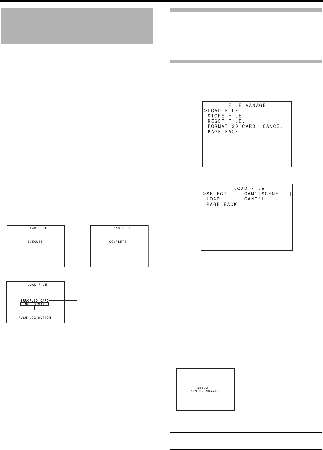
MENU SCREENS
100
FILE MANAGE Menu
Screen
You can perform the following operations in the FILE MAN-
AGE menu screen.
• Settings corresponding to shooting conditions can be read
immediately with the following read-only files.
LIVE HD60P : Ideal setting for HD60P format
LIVE HD50P : Ideal setting for HD50P format
CINEMA HD24P : Ideal setting for movie-quality shoot-
ing
* The read-only files listed above cannot be saved or
reset.
• Save menu settings (Camcorder: CAM1, 2, 3, 4; SD mem-
ory card: EXT1, 2, 3, 4) to files.
• Load saved files.
• You can set a SUB NAME for the file to be saved.
• Reset the menu settings to the factory settings.
• Initialize (format) an SD memory card.
• When you set CANCEL for the LOAD, STORE, RESET
and FORMAT SD CARD items, these operations are not
executed.
• A message is displayed in the LCD monitor or the view-
finder.
EXECUTE : Displayed for 3 seconds
COMPLETE : Displayed for 3 seconds
ERROR : Flashes (Error displays XSee page 101.)
If there is an error:
• Press the STATUS button → Return to the normal
screen.
• Press the SHUTTER dial → Return to the FILE MAN-
AGE menu screen.
• To exit the FILE MANAGE screen:
Move the cursor (K) to PAGE BACK and press the SHUT-
TER dial or press the STATUS button.
Displaying the FILE MANAGE menu
screen
Select the FILE MANAGE.. item on the TOP MENU screen.
Loading a menu settings file
Select the LOAD FILE.. item on the FILE MANAGE menu
screen.
1. Turn the SHUTTER dial, bring the cursor (K) to SELECT
and press the SHUTTER dial.
• The file name setting area flashes.
2. Turn the SHUTTER dial, select the file to load and press
the SHUTTER dial.
3. Turn the SHUTTER dial, bring the cursor (K) to the
LOAD item and press the SHUTTER dial.
• EXECUTE flashes.
4. With EXECUTE selected, press the SHUTTER dial to
read the menu settings in the selected file.
If the current menu settings and the menu settings to be
loaded have different video format settings, “REBOOT!”
is displayed for 3 seconds, this device turns off automati-
cally and then turns on.
CAUTION
This device cannot load scene files from GY-HD100/GY-
HD110-series devices.
Execute Complete
Error
Flashing
Error display
FILE MANAGE menu screen
Reboot display

101
Saving settings
Select the STORE FILE.. item on the FILE MANAGE menu
screen.
1. Turn the SHUTTER dial, bring the cursor (K) to SELECT
and press the SHUTTER dial.
• The file name setting area flashes.
2. Turn the SHUTTER dial, select the file to save to, and
press the SHUTTER dial.
Setting a SUB NAME
If you do not want to set a SUB NAME, go to Step 5..
3. Turn the SHUTTER dial, bring the cursor (K) to SUB
NAME and press the SHUTTER dial.
• The first character in the file name flashes.
4. Turn the SHUTTER dial, select the character, and press
the SHUTTER dial.
• The second character in the file name flashes.
Repeat Step 4. up through the eighth character.
5. Turn the SHUTTER dial, bring the cursor (K) to the
STORE item and press the SHUTTER dial.
• EXECUTE (if the file already exists, “OVERWRITE”)
flashes.
6. With EXECUTE selected, turn the SHUTTER dial to save
the menu settings to the selected file.
Error displays
• NO CARD:
No SD memory card is inserted.
Insert an SD memory card.
•NO FORMAT:
The SD memory card is not initialized (formatted).
Initialize (format) the SD memory card.
• NO ACCESS:
There is a problem with the SD memory card.
Replace the SD memory card.
• WRITE PROTECT:
The SD memory card may be write-protected.
Check that write-protection is disabled.
• DISK FULL:
The SD memory card does not have enough free space.
Delete unwanted data or initialize (format) the card.
• INVALID VIDEO FORMAT:
A settings file for a video format that is not supported was
called up.
Settings files for video formats that are not supported can-
not be called up.
• READ ONLY FILE:
Indicates a read-only file.
Read-only files cannot be saved.
Settable Characters
Space
Execute Complete
Error
Flashing
Error display
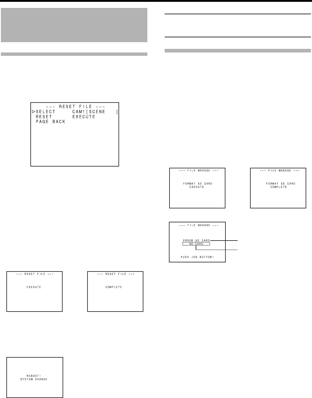
MENU SCREENS
102
FILE MANAGE Menu Screen
(Cont’d)
Resetting the menu settings to the
factory settings
Select the RESET FILE.. item on the FILE MANAGE menu
screen.
1. Turn the SHUTTER dial, bring the cursor (K) to SELECT
and press the SHUTTER dial.
• The file name setting area for the file to be reset
flashes.
2. Turn the SHUTTER dial, select the name of the file to
reset, and press the SHUTTER dial.
CAM1, CAM2, CAM3, CAM4, CURRENT (current set-
tings)
3. Turn the SHUTTER dial, bring the cursor (K) to the
RESET item and press the SHUTTER dial.
• EXECUTE flashes.
4. With EXECUTE selected, press the SHUTTER dial to
reset the settings.
If the current menu settings and the factory settings have
different video format settings, “REBOOT!” is displayed
for 3 seconds, this device turns off automatically and then
turns on.
When this happens, the SUB NAME initial value,
“[SCENE]” is displayed.
MEMO
Even if CAM1, CAM2, CAM3, or CAM4 are reset, the cur-
rent settings are not reset.
To reset the currently set values, select “CURRENT”.
Initializing (formatting) an SD mem-
ory card
Before initializing (formatting) a card:
1Insert and remove the SD memory card with the power
to this device OFF.
2Disable write-protection on the SD memory card.
3Check that an SD memory card has been inserted into
this device.
1. Turn the SHUTTER dial, bring the cursor (K) to the FOR-
MAT SD CARD item and press the SHUTTER dial.
• CANCEL flashes.
2. Turn the SHUTTER dial, and when EXECUTE flashes,
press the SHUTTER dial to initialize (format) the card.
If there is an error:
Check items 2 and 3 in “Before initializing (formatting) a
card”.
Execute Complete
Reboot display
Execute Complete
Flashing
Error display
Error
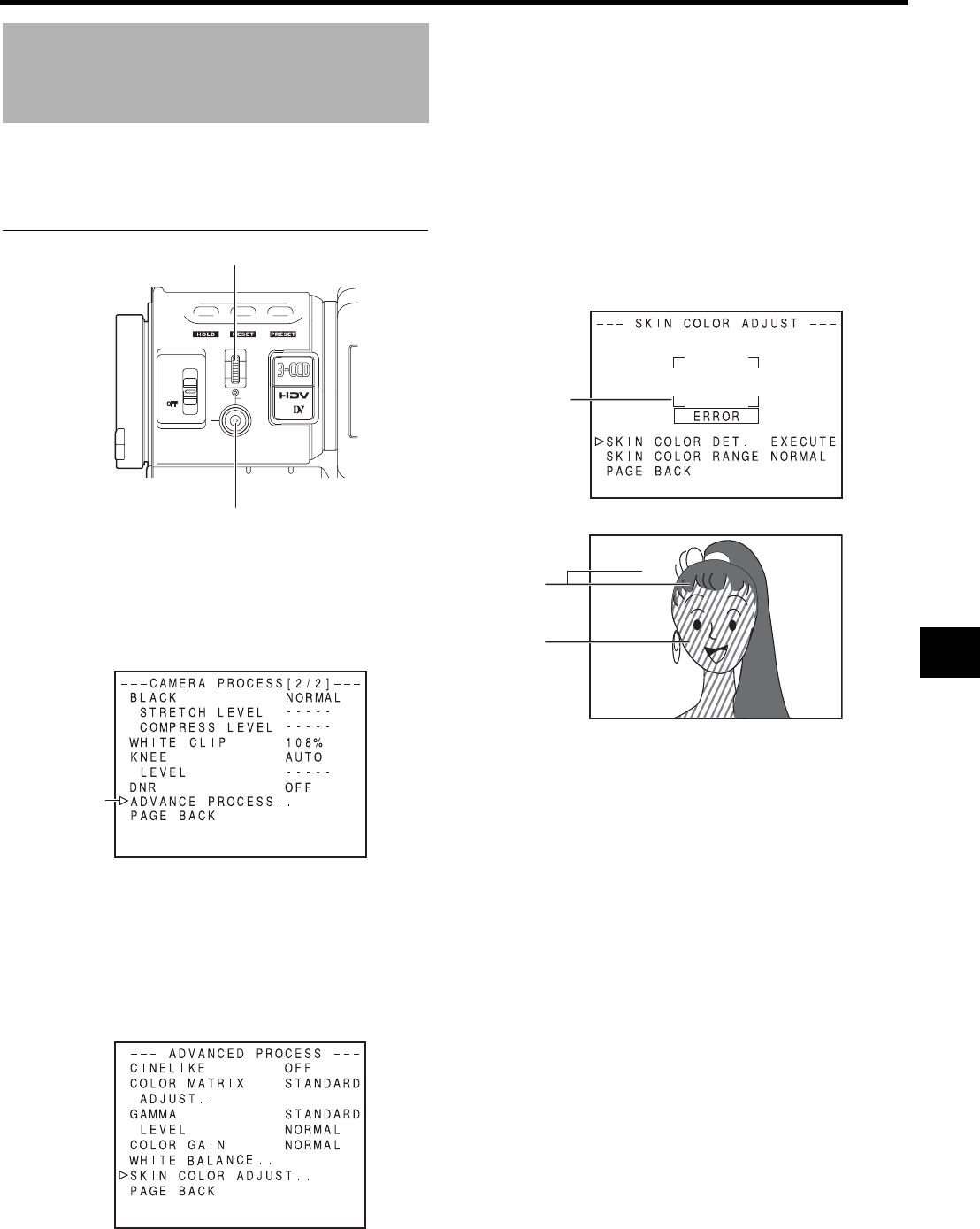
103
FEATURES OF THE CAMERA SECTION
How to Use Skin Detail
This function suppresses edge sharpening in the skin color
areas of the video signal, enabling velvety, smooth skin tones.
Setting the skin detail function color and range
1. Display the ADVANCED PROCESS menu screen.
In menu setting procedure
TOP MENU screen → CAMERA PROCESS[1/2] →
CAMERA PROCESS[2/2] → Select ADVANCED PRO-
CESS item.
2. Turn the SHUTTER dial, bring the cursor (K) to the SKIN
COLOR ADJUST item and press the SHUTTER dial.
• The SKIN COLOR ADJUST screen is displayed.
• The entire screen becomes black and white, and only
the areas recognized by the skin detail function are
displayed in color.
3. Move the cursor (K) to the SKIN COLOR DET. item,
press the SHUTTER dial and select EXECUTE to switch
to skin color detection mode.
4. Shoot so that the color area you want to detect within the
detection area frame is input.
To confirm the detection area, press the SHUTTER dial
and set SKIN COLOR DET. to STOP.
• The frame on the screen is the detection area for the
skin detail function.
• The color within the detection area is recognized as
the color that the skin detail function will use.
• If the color within the detection area is not recognized
as the color that the skin detail function will use,
“ERROR” is displayed on the screen.
5. If you want to change the range of colors recognized with
the skin color detection function, follow the steps below.
1Turn the SHUTTER dial, bring the cursor (K) to the
SKIN COLOR RANGE item and press the SHUTTER
dial.
→ The setting area flashes and can be changed.
2Turn the SHUTTER dial up or down to widen or narrow
the color range.
• Set the range as you check the color display.
3To confirm the color range, press the SHUTTER dial.
• The setting returns to its lit state.
6. To stop the SKIN COLOR ADJUST function, turn the
SHUTTER dial, bring the cursor (K) to the PAGE BACK
item and press the SHUTTER dial.
USER 3USER 2USER 1
STATUS
MENU
2
1
ND FILTER
SHUTTER
SHUTTER dial
STATUS button
Cursor
CAMERA PROCESS[2/2] menu screen
ADVANCED PROCESS menu screen
Detection
area
SKIN COLOR ADJUST menu screen
Black and
white
presenta-
tion
Color
presenta-
tion
SKIN COLOR ADJUST screen
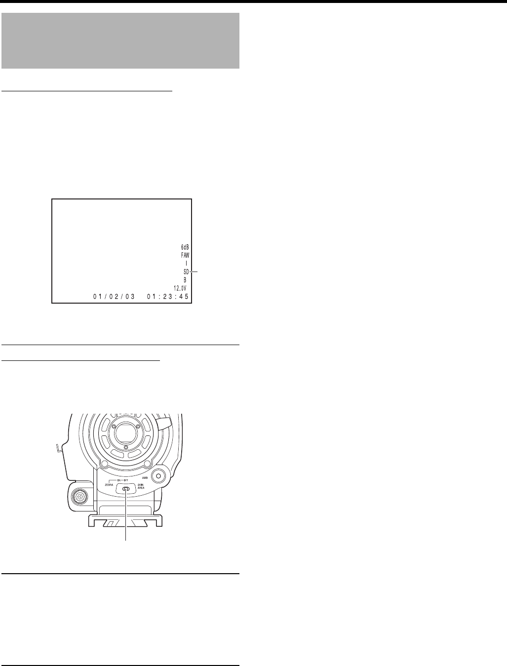
FEATURES OF THE CAMERA SECTION
104
How to Use Skin Detail
(Cont’d)
Using the Skin Detail Function
To use the skin detail function set on the SKIN COLOR
ADJUST screen, select “ON” for the SKIN DETECT item on
the CAMERA PROCESS[1/2] menu screen.
In addition, you can use the LEVEL item to set three levels of
suppression of skin color area detail enhancement in the
video signal. XSee page 81.
While the skin detail function operates, the “SD” indicator is
displayed on the STATUS 0 and STATUS 1 screen in the
viewfinder or LCD monitor.
Confirming the color tone area adjusted
with the Skin Detail function
When you push the ZEBRA switch on the front panel to
“SKIN AREA”, the skin detail function turns ON, and the color
area adjusted with the skin detail function is displayed in
color in the LCD monitor or viewfinder.
MEMO
• When the REVERSE PICTURE item in the CAMERA
PROCESS[2/2] menu screen is set to ROTATE, skin
detail function is available but the detection area is not
displayed in the viewfinder or LCD screen.
• When COLOR GAIN item on the ADVANCED PRO-
CESS menu screen is set to “OFF”, only the portion the
skin detail function is working is displayed in skin color.
XSee page 83.
STATUS 0
“SD” display
ZEBRA switch
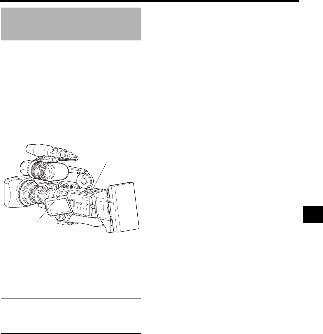
105
Outputting Color Bars
GY-HD250/GY-HD251 can output three types of color bars,
depending on the camera settings.
To output color bars, make the following settings.
1. Turn the FULL AUTO switch to “OFF”.
2. Set the BARS item on the CAMERA OPERATION menu
screen to “ON”. XSee page 80.
• Color bars are output.
Outputting color bars using the USER buttons
1. Turn the FULL AUTO switch to “OFF”.
2. Assign “BARS” to one of the USER1, 2 or 3 buttons.
XSee “SWITCH MODE Menu Screen” on page 86.
3. Press the USER button to which “BARS” was assigned.
• Color bars are output.
MEMO
• You can select whether to output an audio test signal
during color bar output using the TEST TONE item on
the AUDIO/MIC[1/2] menu screen. XSee page 87.
• Color bars are not output when FULL AUTO mode is ON
or in VTR mode.
NTSC standard : Outputs color bars compliant with the
SMPTE standard.
PAL standard : Outputs color bars compliant with the
EBU standard.
16:9 screen : Outputs multi-format color bars.
FULL AUTO switch
USER button
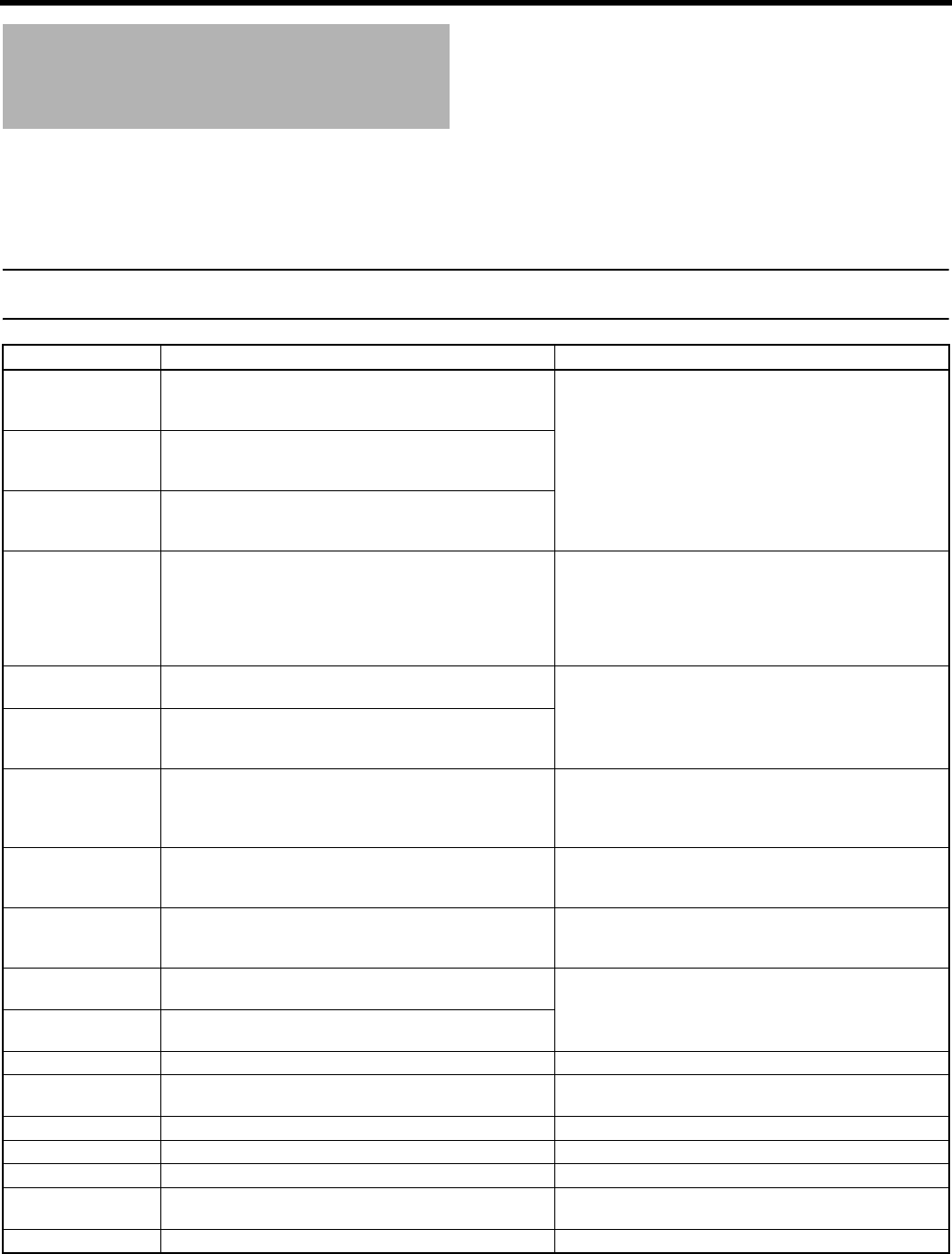
106
OTHERS
Warnings and Responses
Warnings are displayed on the LCD monitor or the viewfinder if there was a mistaken operation, if the battery or tape is low, or if
there is a problem on the VTR.
In addition, if the tape or battery is low or the VTR has a problem, the tally lamp flashes (or lights) and an alarm is output from the
monitor speaker or PHONES jack.
MEMO
GY-HD250/GY-HD251 uses microcomputers. It may not operate properly if there is external static or interference. If this hap-
pens, turn the power off and then on again.
Display Status Action
60/30 INHIBIT
CHANGE FRAME
RATE MENU
The FRAME RATE item is set to 50/25 or 24, and a tape re-
corded in 60/30 frame is played back or it is input into the
IEEE1394 port in VTR mode.
Sets the FRAME RATE item on the VIDEO FORMAT menu
screen to match the frames.
XSee page 77.
50/25 INHIBIT
CHANGE FRAME
RATE MENU
The FRAME RATE item is set to 60/30 or 24, and a tape re-
corded in 50/25 frame or it is input into the IEEE1394 port
in VTR mode.
24 INHIBIT CHANGE
FRAME RATE MENU
The FRAME RATE item is set to 50/25 or 60/30, and a tape
recorded in 24 frame is played back or it is input into the
IEEE1394 port in VTR mode.
AUX IN INHIBIT
CHANGE
FRAME RATE MENU
• U model
Displays when the FRAME RATE item is set to 50/25 or
24 and the GENLOCK/AUX IN switch is set to AUX IN.
• E model
Displays when the FRAME RATE item is set to 60/30 or
24 and the GENLOCK/AUX IN switch is set to AUX IN.
Set the FRAME RATE item as shown below to input exter-
nal images.
U model : 60/30
E model : 50/25
SYNC LOCKING Camera image is locking to external synchronization sig-
nals.
It is not possible to enter recording mode while “SYNC
LOCKING” is displayed. Wait until the indication disap-
pears.
PLEASE WAIT Displays when external synchronization signal is input and
REC trigger button is pressed while SYNC LOCKING is dis-
played.
INVALID SYNC • Displays when the FRAME RATE item is set to 60/30 or
24 and signals not supported by GENLOCK are input.
• Displays when the FRAME RATE item is set to 50/25 and
signals not supported by GENLOCK are input.
Input supported external synchronization signals.
XSee page 66.
DV-60I INVALID!
DV-24P INVALID!
DV-24PA INVALID!
A tape recorded in DV-60I, DV-24P, or DV-24PA format
was played back or input into the IEEE1394 connector in
VTR mode on the E model.
The E model cannot play back tapes recorded in DV-60I,
DV-24P or DV-24PA format or input into the IEEE1394 con-
nector in VTR mode.
DV-50I INVALID!
DV-25P INVALID!
A tape recorded in DV-50I or DV-25P format was played
back or input into the IEEE1394 connector in VTR mode on
the U model.
The U model cannot play back tapes recorded in DV-50I or
DV-25P format or input into the IEEE1394 connector in
VTR mode.
HDV-SD60P
INVALID!
A tape recorded in HDV-SD60P format was played back or
input into IEEE1394 connector in VTR mode.
GY-HD250/GY-HD251 cannot play back or input an HDV-
SD60P/HDV-SD50P signal.
HDV-SD50P
INVALID!
A tape recorded in HDV-SD50P format was played back or
input into IEEE1394 connector in VTR mode.
INVALID TAPE! A computer data tape or a DVC PRO cassette was used. Use a MiniDV videocassette.
LP TAPE INVALID!* Tried to play back a tape recorded in LP mode. GY-HD250/GY-HD251 cannot record or play back in LP
mode.
NO DV SIGNAL* DV signal was not input. Set the IEEE1394 switch to DV and input a DV signal.
NO HDV SIGNAL* HDV signal was not input. Set the IEEE1394 switch to HDV and input an HDV signal.
COPY INHIBIT* Tried to record a copyguarded signal. Cannot record a copyguarded signal.
REC INHIBIT* A tape that cannot be recorded (back switch is set to SAVE)
was inserted.
Set the switch on the back of the cassette tape to REC.
NO TAPE* No videocassette tape is inserted. Insert a cassette tape.

107
* When status indications are magnified, warnings are not displayed on the LCD monitor.
XSee “Magnified Status Indications on the LCD Monitor” on page 29.
Display Status Action
CHANGE PB TAPE
FORMAT*
Image format which is different from the one set in the PB
TAPE item on the VIDEO FORMAT[2/2] menu screen is be-
ing played back.
Check the setting for the PB TAPE item.
XSee page 79.
LOW VOLTAGE* Battery is low. Charge the battery pack or replace it.
TAPE NEAR END* There are less than 3 minutes remaining on the tape (flash-
es only when recording).
To continue shooting, find a new tape or replace the tape.
TAPE END* Displayed when the tape ends. Replace the tape.
CHANGE 1394
SWITCH*
Recording or playback video format and the IEEE1394 set-
ting is different when connected to the IEEE1394 port.
Set the IEEE1394 switch correctly, turn the power off and
then on again.
SWITCH TO VTR
MODE*
Tried to use the FF or REW button in camera mode. Press the CAM/VTR button to set VTR mode.
HEAD CLEANING
REQUIRED
Displayed when the video head is dirty. (Head clogging was
detected during an edit search in shooting mode as well as
during playback and displayed.)
Clean with a special head cleaning tape.
XSee page 7.
CLEANING TAPE! Displayed when a head cleaning tape is inserted. The display disappears when the head cleaning tape is re-
moved.
COPY GUARD!* Tried to play back a copyguarded tape. Cannot play back a copyguarded tape.
FAN MOTOR HOUR Over the prescribed fan motor usage time. Please contact your local dealer or JVC.
PUSH CASSETTE
COVER*
The videocassette cover is not firmly shut. Lightly push the top center of the videocassette cover.
CHANGE THE SYS-
TEM*
Displayed when you attempt to change FRAME RATE item
in the VIDEO FORMAT menu screen.
When the FRAME RATE item setting is changed, the frame
rate system for this device is changed. Check the frame
rate to use before changing the setting.
XSee pages 54 and 77.
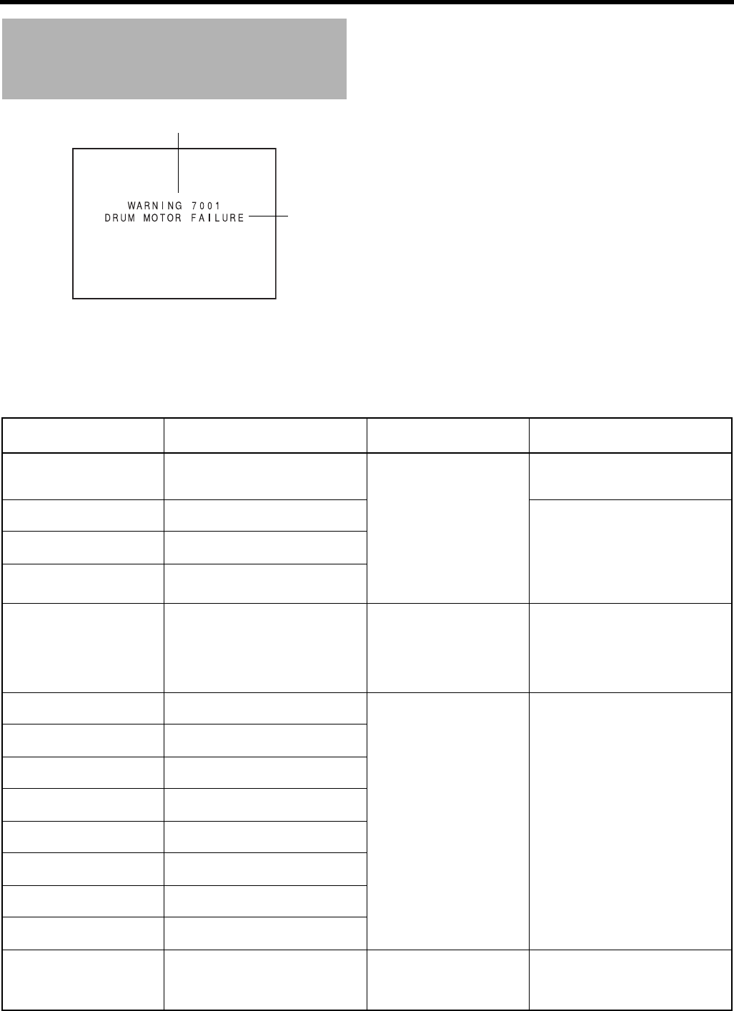
OTHERS
108
Warnings and Responses (Cont’d)
• Warning Indications for VTR Abnormalities
Should malfunctions occur during VTR operation, this
device self-diagnoses the cause and shows the diagnose
together with an error code on the LCD monitor or in the
viewfinder.
Error code
Warning
Error Code Error Details GY-HD250/GY-HD251
Operation Remedy
0201
CONDENSATION ON DRUM
Indicates dew formation (condensa-
tion).
Operation stops. All opera-
tions are rejected.
Leave this device with the power ON,
until the indication disappears.
XSee page 9.
3200
LOADING FAILURE
Tape cannot be loaded. Switch the power OFF and then switch
it back ON. However, the tape may be
damaged depending on the circum-
stances. Please consult the person in
charge of professional video equip-
ment at your nearest JVC-authorized
service agent.
3300
UNLOADING FAILURE
Tape cannot be unloaded.
4100
CASSETTE EJECT FAILURE
Irregularity with eject operation.
5605 - 5609
DEFECTIVE TAPE
Tape is cut. Operation stops. Press the EJECT button to take out the
cassette.
If the tape runs out during recording,
switch the power OFF and then switch
it back ON, press the EJECT button,
and then take out the cassette.
5702
TAPE END DET. ERROR
Tape end sensor error. Operation stops. All opera-
tions are rejected.
Switch the power OFF and then switch
it back ON. However, the tape may be
damaged depending on the circum-
stances. Please consult the person in
charge of professional video equip-
ment at your nearest JVC-authorized
service agent.
5802
TAPE BEGIN DET. ERROR
Tape beginning sensor error.
7001
DRUM MOTOR FAILURE
Drum rotation error.
7101
CAP MOTOR FAILURE
Capstan rotation error.
7202 - 7203
SUPPLY REEL FAILURE
Supply reel rotation error.
7302 - 7303
TAKE UP REEL FAILURE
Take up reel rotation error.
7305
TAKE UP REEL FAILURE
Take up reel rotation error when un-
loading.
8000
EMERGENCY TAPE!
Tape problem detected.
TURN POWER OFF.
TURN BACK ON LATER.
System error when power is turned on. HDV/DV LED, VTR indicator
and TALLY lamp flash. Only
POWER switch operation is
accepted.
Turn off the power and let this device
sit for sometime before turning it back
on.
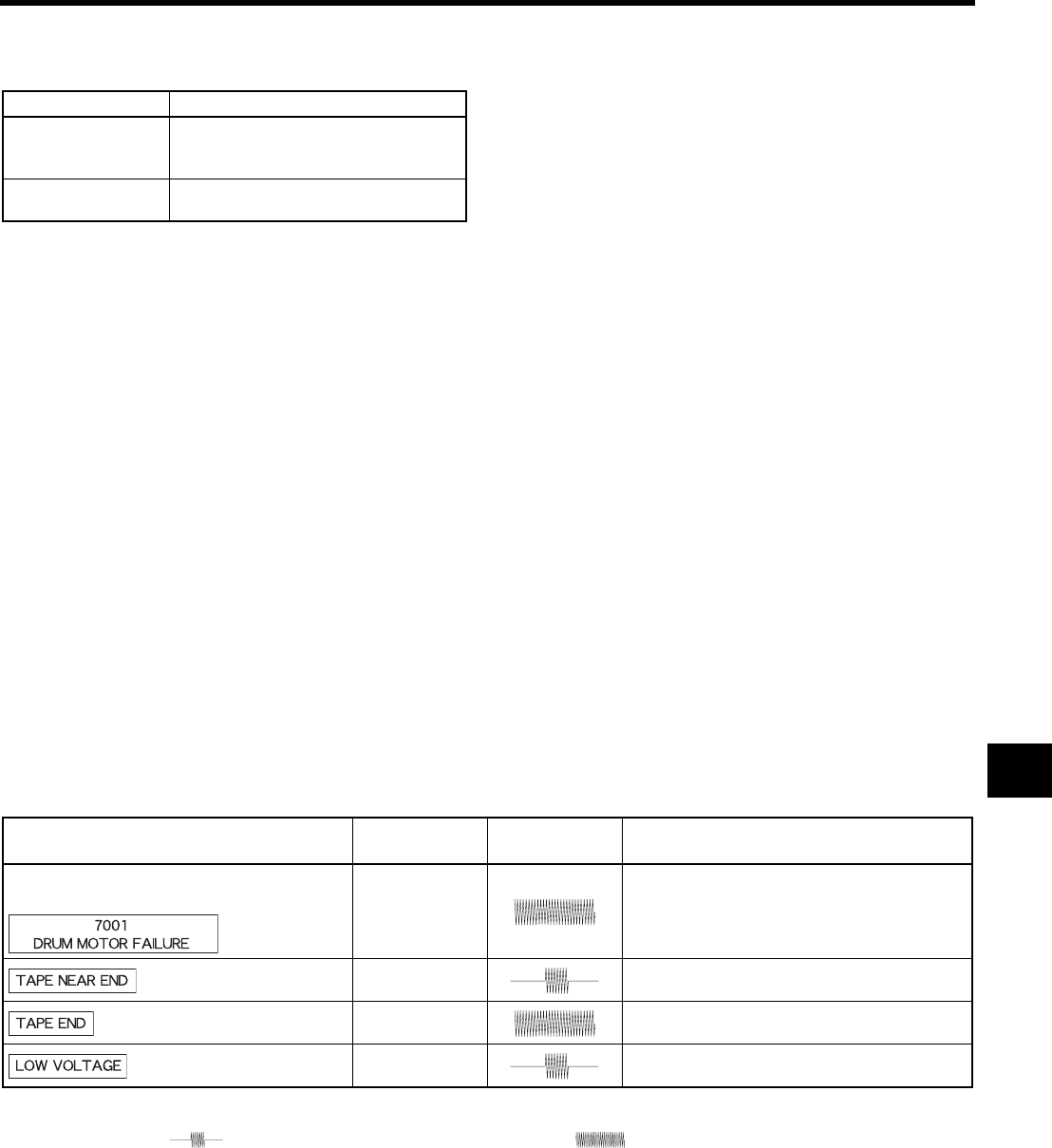
109
TALLY lamp
Blinks when remaining battery power or tape is low. (Only
in Camera mode)
Alarm Sound
When remaining battery power becomes low, a warning
sound is output from the monitoring loudspeaker and the
PHONES jack.
(In Camera mode only)
When an irregularity occurs in the VTR, a warning sound
is also output.
Whether or not alarm sound should be output and the vol-
ume level are selected with the ALARM VR LEVEL item
on the OTHERS[1/2] menu screen.
Depending on the alarm conditions, the warning indicators
on the LCD monitor/viewfinder screen, the TALLY lamp,
and alarm sounds appear as shown in the following table.
Blinking Pattern Remaining Battery/Tape
Slow blinking
(once per sec.)
• Remaining battery power is low.
• Remaining tape time is equivalent to less
than 3 minutes.
Fast blinking
(four times per sec.)
• Tape has run out.
• Irregularity has occurred in the VTR.
Alarm Indications on LCD Monitor/
Viewfinder Screen TALLY lamp Alarm Sound Condition
VTR alarm indication
(Example) I
Dew formation (condensation) or error has oc-
curred in the VTR.
JAbout 3 min. before tape end
(displayed during recording).
ITape end
(displayed during recording).
JRemaining battery power is low.
Display symbols J: Blinking once per second. I: Blinking four times per second.
: Sound interrupted once per second. : Continuous sound.

OTHERS
110
Troubleshooting
Symptoms Remedy
Power cannot be switched ON. • Is power supply connected correctly?
• Is battery pack recharged?
• Was the power turned ON immediately after being turned OFF?
Wait at least 5 seconds before turning the power ON again once it has been
turned OFF.
Recording is not possible. • Is the REC LOCK switch on the handle set to ON?
• Is the switch on cassette set to “REC”? If it is set to “SAVE”, set it to “REC”.
• The Camera mode has not been selected. (The VTR indicator does not light.)
While the VTR indicator lights, press the MODE switch upward to turn on the
CAM indicator.
Camera image does not appear on LCD monitor or in viewfind-
er.
• The Camera mode has not been selected. (The VTR indicator does not light.)
While the VTR indicator lights, camera image will not be output.
Press the CAM/VTR switch upward to turn on the VTR indicator.
Image shown on LCD monitor or in viewfinder is dark or blurred. • Adjust the brightness of the LCD monitor or viewfinder screen.
• Is the ND filter knob set to 2?
• Is the iris closed?
• Is the shutter speed too fast?
• Is the viewfinder cable correctly connected?
Playback does not start when the play button is pressed. • In the Camera mode, is “STOP” indicated as the VTR operation mode indica-
tor?
When “STBY” is indicated, press the STOP button to display “STOP”.
Cannot play back. • Is the PB TAPE item on the VIDEO FORMAT menu screen set to a setting oth-
er than AUTO?
If this menu item and the tape format do not match, the tape cannot be played
back.
Cannot input an HDV/DV signal. • Is this device in VTR mode? (Is the VTR indicator lit?)
• Is the IEEE1394 switch set correctly?
Noise interferes with playback video. • Video head may be clogged with dirt. Clean head with the special head clean-
ing tape. XSee “Precautions for Use of Head Cleaning Tape” on page 7.
Sound is not output during playback. • Is the AUDIO SELECT item on the AUDIO menu screen set to CH3/4?
To output the sound of the recording, set to CH1/2.
Noise appears when playing back a tape recorded on another
unit.
• When a tape recorded on another unit is played back or used for recording,
this phenomenon may occur due to tracking errors.
The transient section between scenes recorded on other units
and those recorded on the GY-HD250/GY-HD251 may appear
disturbed.
The front section’s audio level control doesn’t work. • Is the CH-1/CH-2 AUDIO SELECT switch set to “AUTO”?
• Is the FULL AUTO switch set to “ON”?
Cannot initialize (format) the SD memory card. • Is the SD memory card write-protected? XSee page 34.
Battery alarm is displayed even if a fully charged battery pack
is put in.
• Is the battery pack old?
Cassette cannot be ejected after the power is turned ON. • The capacity of the power supply may be insufficient. Check the power volt-
age.
Time code or user’s bits data not displayed. • Is the TC/UB item on the LCD/VF[3/4] menu screen set to OFF?
If so, set to ON.
The date and time are not displayed or recorded. • Is the DISPLAY item on the TIME/DATE menu screen set to OFF?
Set to ON when the data should be displayed and recorded.
• Is the date and time setting made? XSee “Setting and Displaying the Date
and Time” on pages 41, 42.
Video is not output from the [Y/PB/PR] terminal. • Is VF SIGNAL on the LCD/VF[4/4] menu screen set to Y or COMPOSITE?
Viewfinder is not displayed properly. • Is VF SIGNAL on the LCD/VF[4/4] menu screen set to a setting other than
RGB?
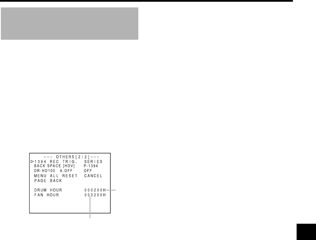
111
How to Display the Hour
Meter
The drum and fan motor usage times are displayed in the
DRUM HOUR item and the FAN HOUR items on the OTH-
ERS[2/2] menu screen as the hour meters on GY-HD250/
GY-HD251.
Use as an estimate for regular maintenance. XSee page 7.
1. Turn the POWER switch ON.
2. Press the STATUS button for at least 1 second to display
the TOP MENU screen.
3. Turn the SHUTTER dial, select the OTHERS.. item, and
press the SHUTTER dial.
The OTHERS[1/2] menu screen is displayed.
4. Select the NEXT PAGE item on the OTHERS[1/2] menu
screen and press the SHUTTER dial.
The OTHERS[2/2] menu screen is displayed.
OTHERS[2/2] Menu Screen
5. To return to the normal screen display, do one of the fol-
lowing:
• Press the STATUS button.
or
• Return to the TOP MENU screen, select the EXIT item
on the TOP MENU screen and press the SHUTTER
dial.
DRUM HOUR item : Displays the drum usage hours.
FAN HOUR item : Displays the fan motor usage
hours.
OTHERS[2/2] menu screen
Drum usage
hours (h)
Fan motor usage hours (h)

OTHERS
112
Specifications
[General]
[Camera section]
[VTR section]
[Time Code]
[Connectors]
Power requirements : DC 12 V, W 2 A
Power consumption : Approx. 24 W (in the Record mode)
Dimensions : 224(W) × 242.3(H) × 401(D) mm
(U model)
224(W) × 242.3(H) × 414(D) mm
(E model)
Mass : 3.6 d(8.0 lbs.) (U model)
3.8 d(8.4 lbs.) (E model)
(including lens (Th16 × 5.5BRMU),
viewfinder, microphone and tape)
Temperature
Operating : 0°C to 40°C (32°F to 104°F)
Storage : –20°C to 60°C (–4F° to 140°F)
Humidity
Operating : 30% to 80% RH
Storage : 85% RH or less
Image pickup device : 1/3" interline-transfer CCDs
Color separation
optical system
: F1.4, 3-color separation prism
Number of total pixels : Approx. 1,110,000 pixels
Color bars : SMPTE/EBU type Sync system:
Internal sync (built-in SSG)
Lens mount : 1/3" bayonet system
ND filter : 1/4ND, 1/16ND
Gain : 0, 3, 6, 9, 12, 15, 18 dB, ALC
Electronic shutter
Standard value : 59.94 Hz (U model)/50 Hz (E model)
Fixed values : 7.5 - 10,000 Hz, 11 steps (HDV
HD30p/HDV HD60p/DV 60i), 6.25 -
10,000 Hz, 11 steps (HDV HD25p/
HDV HD50p/DV 50i), 6 - 10,000 Hz,
12 steps (HDV HD24p/DV 24p),
6.25 - 10,000 Hz, 11 steps (DV 25p)
Variable scan : 30.03 - 10,489.5 Hz (HDV HD60p/
HDV HD30p/DV 60i)
25.04 - 10,489.5 Hz (HDV HD50p/
HDV HD25p/DV 50i/DV 25p)
24.01 - 10,489.5 Hz (HDV HD24p/
DV 24p)
Dynamic range : 300% or more
Video
Recording format : 720/24p, 720/25p, 720/30p, 720/
50p, 720/60p (U/E model), 480/24p,
480/60i (U model), 576/25p, 576/50i
(E model)
Video Format:
[HDV]
Video signal record-
ing format
: HDV720p format, 8-bit, 19.7 Mbps
Compression : MPEG-2 video (profile & level:
MP@H-14)
[DV]
Video signal record-
ing format
: DV format, 8-bit, 25 Mbps
Compression : DV compression, 4:1:1 (NTSC)/
4:2:0 (PAL)
Audio:
[HDV]
Audio signal record-
ing format
: MPEG1 Audio Layer II
[DV]
Audio signal record-
ing format
: 16-bit (locked audio), 48 kHz PCM
for 2 channels or 12-bit, 32 kHz
PCM for 4 channels
Usable tape : MiniDV tape
Tape speed : 18.8 mm/sec.
Record/play time : 63 minutes (with an M-
DV63PROHD tape)
Time code signal : Compliance with SMPTE/EBU stan-
dard
LTC input :
0 dBs±6 dBs, high impedance, unbal-
anced
LTC output : 0 dBs±6 dBs, low impedance, unbal-
anced
AUX input
: Composite video signals 1V (p-p)
±0.3V (p-p). 75 Ω unbalanced (BNC)
Genlock input
: BB signals
SMPTE 170M (RS-170A) compliant
NTSC
/ITU-R BT. 470-6 compliant PAL
HDTV Tri-sync signals
[SMPTE 296M/SMPTE 274M com-
pliant] (BNC)
Analog composite output
: 1.0 V (p-p), 75 Ω, unbalanced (RCA)
Analog component output
Y : 1.0 V (p-p), 75 Ω, unbalanced (BNC)
PB/PR: 0.7 V (p-p), 75 Ω, unbalanced (BNC)
HD/SD SDI output
: SMPTE 292M compliant HD serial
digital signals
/SMPTE 259M compliant SD serial
digital signals (BNC)
Audio inputs
Mic : –60 dBs, 3 kΩ, balanced (XLR), +48
V output for phantom power supply
Line : +4 dBs, 10 kΩ, balanced (XLR)
Audio outputs : –8 dBs, low impedance, unbalanced
(RCA ×2)
Earphone jack : –17 dBs to –60 dBs, 8-Ω impedance
(stereo mini-jack ×2)
IEEE1394 connector : 6-pin
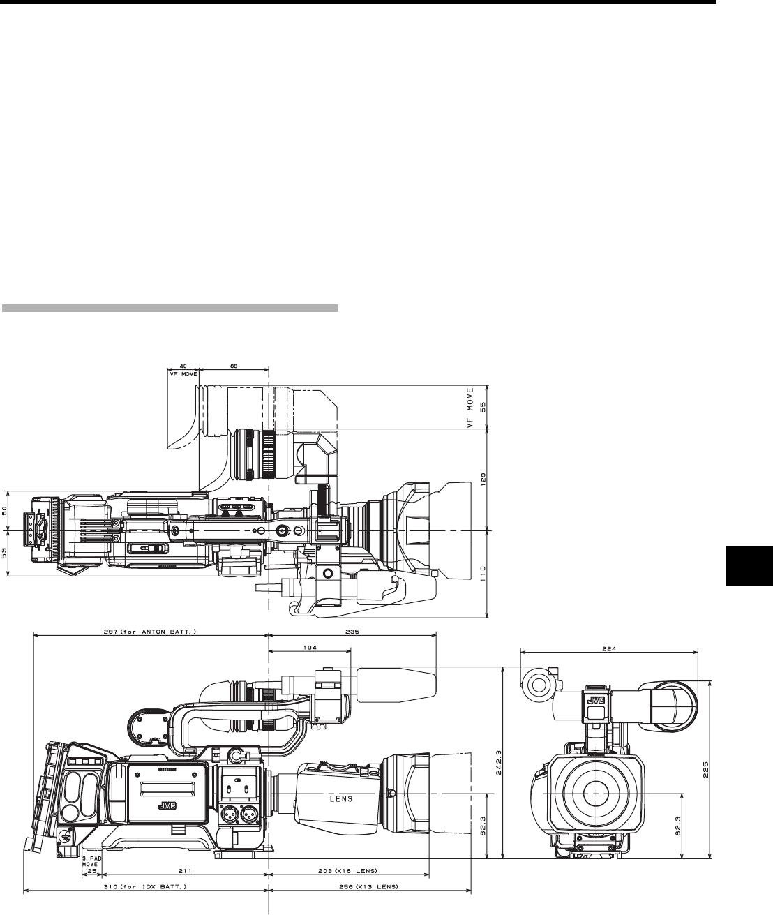
113
[ACCESSORIES]
For details, consult your JVC dealer.
EXTERNAL DIMENSIONS
* Design and specifications are subject to change without notice.
Lens : 1 (Excluding the CHU/CHE model)
Microphone : 1
Core Filter : 1
Clamp Filter : 4
SD memory card : 1
Tripod base : 1 (U model only)
Instruction Manual : 1
Warranty Card : 1
(USA and Canada only)
(unit: mm)

INTRODUCTION
CONTROLS,
INDICATORS AND
CONNECTORS
PREPARATIONS
PREPARATIONS
FOR OPERATION
SETTING AND
ADJUSTMENTS
BEFORE SHOOTING
SHOOTING
OPERATION
PLAYBACK MODE
USING EXTERNAL
COMPONENTS
MENU SCREENS
FEATURES OF THE
CAMERA SECTION
OTHERS
HD CAMERA RECORDER
INSTRUCTIONS
GY-HD250
GY-HD251
* The illustration shows the GY-HD250/GY-
HD251 HD CAMERA RECORDER with the
provided lens, viewfinder and microphone
attached.
LST0440-001B
E
GY-HD250/GY-HD251
HD CAMERA RECORDER
Thank you for purchasing this JVC product. Before operating this
device, please read the instructions carefully to ensure the best
possible performance.
For Customer Use:
Enter below the Serial No. which is located on the body.
Retain this information for future reference.
Model No.
Serial No.
© 2006 Victor Company of Japan, Limited LST0440-001B
