JVC HR S3500U User Manual Instructions LPT0024 001B
User Manual: JVC HR-S3500U Instructions
Open the PDF directly: View PDF ![]() .
.
Page Count: 68
HR-S3500U
VIDEO CASSETTE RECORDER
INSTRUCTIONS
LPT0024-001B
For Customer Use:
Enter below the Model No. and
Serial No. which are located on the
rear of cabinet. Retain this
information for future reference.
Model No.
Serial No.
REW
SP/EP
PAUSE
REC
STOP/EJECT
PLAY
TV/VCR
FF
JOG
SHUTTLE
MENU OK
POWER
VIDEO
(MONO)
L –AUDIO– R
REC LINK
S-VHS ET
CH
SP VCR
T
V
C
H
+
T
V
V
O
L
–
T
V
C
H
–
T
V
V
O
L
+
TV
CANCEL
TIMER
START STOP DATE
PLAY
REW
REC
STOP
SHUTTLE
PLUS
PAUSE
FF
MENU
OK
CH
POWER
TV/VCR
C. RESET
DBS DAILY(M-F)
AUX
WEEKLY
PROG
CHECK
PROG SP/EP SKIP SEARCH
DISPLAY
ENTER/OSD
CABLE/
DBS
123
456
789
0
2
4
1
3
EXPRESS PROGRAMMING
MULTI BRAND
REMOTE CONTROL UNIT
MBRSET
A/B
2 EN
Dear Customer,
Thank you for purchasing the JVC VHS video cassette recorder. Before use, please read the safety information and precautions
contained in the following pages to ensure safe use of your new VCR.
CAUTIONS
WARNING:
TO PREVENT FIRE OR SHOCK
HAZARD, DO NOT EXPOSE THIS
UNIT TO RAIN OR MOISTURE.
CAUTION:
This video cassette recorder should be used with AC
120V`, 60Hz only.
To prevent electric shocks and fire hazards, DO NOT use
any other power source.
CAUTION:
TO PREVENT ELECTRIC SHOCK, MATCH WIDE
BLADE OF PLUG TO WIDE SLOT, FULLY INSERT.
ATTENTION:
POUR ÉVITER LES CHOCS ÉLECTRIQUES, INTRODUIRE
LA LAME LA PLUS LARGE DE LA FICHE DANS LA BORNE
CORRESPONDANTE DE LA PRISE ET POUSSER
JUSQU'AU FOND.
CAUTION
RISK OF ELECTRIC SHOCK
DO NOT OPEN
CAUTION: TO REDUCE THE RISK OF ELECTRIC SHOCK.
DO NOT REMOVE COVER (OR BACK).
NO USER-SERVICEABLE PARTS INSIDE.
REFER SERVICING TO QUALIFIED SERVICE PERSONNEL.
The lightning flash with arrowhead symbol, within an equilateral
triangle, is intended to alert the user to the presence of
uninsulated "dangerous voltage" within the product's enclosure
that may be of sufficient magnitude to constitute a risk of electric
shock to persons.
The exclamation point within an equilateral triangle is intended to
alert the user to the presence of important operating and
maintenance (servicing) instructions in the literature
accompanying the appliance.
Failure to heed the following precautions may result in
damage to the VCR, remote control or video cassette.
1. DO NOT place the VCR . . .
... in an environment prone to extreme temperatures or
humidity.
... in direct sunlight.
... in a dusty environment.
... in an environment where strong magnetic fields are
generated.
... on a surface that is unstable or subject to vibration.
2. DO NOT block the VCR’s ventilation openings.
3. DO NOT place heavy objects on the VCR or remote control.
4. DO NOT place anything which might spill on top of the
VCR or remote control.
5. AVOID violent shocks to the VCR during transport.
**MOISTURE CONDENSATION
Moisture in the air will condense on the VCR when you move it
from a cold place to a warm place, or under extremely humid
conditions—just as water droplets form on the surface of a glass
filled with cold liquid. Moisture condensation on the head drum
will cause damage to the tape. In conditions where condensa-
tion may occur, keep the VCR’s power turned on for a few
hours to let the moisture dry before inserting a tape.
**ABOUT HEAD CLEANING
Accumulation of dirt and other particles on the video heads
may cause the playback picture to become blurred or inter-
rupted. Be sure to contact your nearest JVC dealer if such
troubles occur.
Note to CATV system installer:
This reminder is provided to call the CATV system
installer's attention to Article 820-40 of the NEC that
provides guidelines for proper grounding and, in particular,
specifies that the cable ground shall be connected to the
grounding system of the building, as close to the point of
cable entry as practical.
CAUTION:
Changes or modifications not approved by JVC could void
user's authority to operate the equipment.
nCassettes marked "S-VHS" and "VHS" can be used with this
video cassette recorder. However, S-VHS recordings are
possible only with cassettes marked "S-VHS".
By using S-VHS ET it is possible to record and play back with
S-VHS picture quality on VHS cassettes with this VCR.
nAs an ENERGY STAR ® Partner, JVC has determined that this
product or product model meets the ENERGY STAR® guidelines
for energy efficiency.
VCR Plus+C3 and PlusCode are trademarks of Gemstar Develop-
ment Corporation.
The VCR Plus+ system is manufactured under license from
Gemstar Development Corporation.
DSSTM is an official trademark of DIRECTV, Inc., a unit of GM
Hughes Electronics. PRIMESTAR is a registered service mark of
Primestar Partners, L.P. DISH NetworkTM is a trademark of
Echostar Communications Corporation.
MOVIE ADVANCETM is a trademark of SRT, Inc. A Jerry Iggulden
invention licensed in association with Arthur D. Little Enter-
prises, Inc.

EN 3
IMPORTANT PRODUCT
SAFETY INSTRUCTIONS
Electrical energy can perform many useful functions. But
improper use can result in potential electrical shock or fire
hazards. This product has been engineered and manufactured
to assure your personal safety. In order not to defeat the built-in
safeguards, observe the following basic rules for its installation,
use and servicing.
ATTENTION:
Follow and obey all warnings and instructions marked on your
product and its operating instructions. For your safety, please
read all the safety and operating instructions before you operate
this product and keep this booklet for future reference.
INSTALLATION
1. Grounding or Polarization
(A) Your product may be equipped with a polarized alternating-
current line plug (a plug having one blade wider than the
other). This plug will fit into the power outlet only one way.
This is a safety feature.
If you are unable to insert the plug fully into the outlet, try
reversing the plug. If the plug should still fail to fit, contact
your electrician to replace your obsolete outlet. Do not
defeat the safety purpose of the polarized plug.
(B) Your product may be equipped with a 3-wire grounding-type
plug, a plug having a third (grounding) pin. This plug will
only fit into a grounding-type power outlet. This is a safety
feature.
If you are unable to insert the plug into the outlet, contact
your electrician to replace your obsolete outlet. Do not
defeat the safety purpose of the grounding-type plug.
2. Power Sources
Operate your product only from the type of power source
indicated on the marking label. If you are not sure of the type of
power supply to your home, consult your product dealer or
local power company. If your product is intended to operate
from battery power, or other sources, refer to the operating
instructions.
3. Overloading
Do not overload wall outlets, extension cords, or integral
convenience receptacles as this can result in a risk of fire or
electric shock.
4. Power Cord Protection
Power supply cords should be routed so that they are not likely
to be walked on or pinched by items placed upon or against
them, paying particular attention to cords at plugs, convenience
receptacles, and the point where they exit from the product.
5. Ventilation
Slots and openings in the cabinet are provided for ventilation.
To ensure reliable operation of the product and to protect it
from overheating, these openings must not be blocked or
covered.
• Do not block the openings by placing the product on a bed,
sofa, rug or other similar surface.
• Do not place the product in a built-in installation such as a
bookcase or rack unless proper ventilation is provided or the
manufacturer’s instructions have been adhered to.
6. Wall or Ceiling Mounting
The product should be mounted to a wall or ceiling only as
recommended by the manufacturer.
ANTENNA
LEAD IN WIRE
ANTENNA
DISCHARGE UNIT
(NEC SECTION
810-20)
GROUNDING
CONDUCTORS
(NEC SECTION 810-21)
GROUND CLAMPS
POWER SERVICE GROUNDING ELECTRODE SYSTEM
(NEC ART 250. PART H)
NEC – NATIONAL ELECTRICAL CODE
ELECTRIC SERVICE
EQUIPMENT
EXAMPLE OF ANTENNA GROUNDING AS PER
NATIONAL ELECTRICAL CODE, ANSI/NFPA 70
GROUND CLAMP
ANTENNA INSTALLATION
INSTRUCTIONS
1. Outdoor Antenna Grounding
If an outside antenna or cable system is connected to the
product, be sure the antenna or cable system is grounded so as
to provide some protection against voltage surges and built-up
static charges. Article 810 of the National Electrical Code,
ANSI/NFPA 70, provides information with regard to proper
grounding of the mast and supporting structure, grounding of
the lead-in wire to an antenna discharge unit, size of grounding
connectors, location of antenna discharge unit, connection to
grounding electrodes, and requirements for the grounding
electrode.
2. Lightning
For added protection for this product during a lightning storm,
or when it is left unattended and unused for long periods of
time, unplug it from the wall outlet and disconnect the antenna
or cable system. This will prevent damage to the product due to
lightning and power-line surges.
3. Power Lines
An outside antenna system should not be located in the vicinity
of overhead power lines or other electric light or power circuits,
or where it can fall into such power lines or circuits. When
installing an outside antenna system, extreme care should be
taken to keep from touching such power lines or circuits as
contact with them might be fatal.

4 EN
SERVICING
1. Servicing
If your product is not operating correctly or exhibits a marked
change in performance and you are unable to restore normal
operation by following the detailed procedure in its operating
instructions, do not attempt to service it yourself as opening or
removing covers may expose you to dangerous voltage or other
hazards. Refer all servicing to qualified service personnel.
2. Damage Requiring Service
Unplug this product from the wall outlet and refer servicing to
qualified service personnel under the following conditions:
a.When the power supply cord or plug is damaged.
b.If liquid has been spilled, or objects have fallen into the
product.
c.If the product has been exposed to rain or water.
d.If the product does not operate normally by following the
operating instructions. Adjust only those controls that are
covered by the operating instructions as an improper
adjustment of other controls may result in damage and will
often require extensive work by a qualified technician to
restore the product to its normal operation.
e.If the product has been dropped or damaged in any way.
f. When the product exhibits a distinct change in
performance—this indicates a need for service.
3. Replacement Parts
When replacement parts are required, be sure the service
technician has used replacement parts specified by the
manufacturer or have the same characteristics as the original
part. Unauthorized substitutions may result in fire, electric
shock or other hazards.
4. Safety Check
Upon completion of any service or repairs to this product, ask
the service technician to perform safety checks to determine
that the product is in safe operating condition.
HOW TO USE THIS INSTRUCTION
MANUAL
●All major sections and subsections are listed in the Table Of
Contents on page 5. Use this when searching for information
on a specific procedure or feature.
●The Index on pages 59–62 lists frequently-used terms, and
the number of the page on which they are used or explained
in the manual. This section also illustrates the controls and
connections on the front and rear panel, the front display
panel and the remote control.
●The Z mark signals a reference to another page for
instructions or related information.
●Operation buttons necessary for the various procedures are
clearly indicated through the use of illustrations at the
beginning of each major section.
BEFORE YOU INSTALL YOUR NEW
VCR . . .
. . . please read the sections/literature listed below.
●”Cautions” on page 2
●”Important Products Safety Instructions” on the previous pages
USE
1. Accessories
To avoid personal injury:
• Do not place this product on an unstable cart, stand, tripod,
bracket, or table. It may fall, causing serious injury to a child
or adult, and serious damage to the product.
• Use only with a cart, stand, tripod, bracket, or table
recommended by the manufacturer or sold with the product.
• Use a mounting accessory recommended by the
manufacturer and follow the manufacturer’s instructions for
any mounting of the product.
• Do not try to roll a cart with small casters across thresholds or
deep-pile carpets.
2. Product and Cart Combination
A product and cart combination
should be moved with care. Quick
stops, excessive force, and uneven
surfaces may cause the product and
cart combination to overturn.
3. Water and Moisture
Do not use this product near water—for example, near a bath
tub, wash bowl, kitchen sink or laundry tub, in a wet basement,
or near a swimming pool and the like.
4. Object and Liquid Entry
Never push objects of any kind into this product through
openings as they may touch dangerous voltage points or short-
out parts that could result in a fire or electric shock. Never spill
liquid of any kind on the product.
5. Attachments
Do not use attachments not recommended by the manufacturer
of this product as they may cause hazards.
6. Cleaning
Unplug this product from the wall outlet before cleaning. Do
not use liquid cleaners or aerosol cleaners. Use a damp cloth
for cleaning.
7. Heat
The product should be situated away from heat sources such as
radiators, heat registers, stoves, or other products (including
amplifiers) that produce heat.
PORTABLE CART WARNING
(Symbol provided by RETAC)

EN 5
CONTENTS
TIMER RECORDING 38
VCR Plus+ Timer Programming ................... 38
VCR Plus+ Setup ......................................... 40
Express Timer Programming ....................... 42
Check, Cancel And Revise Programs .......................44
Auto SP→EP Timer ..................................................45
Auto Timer...............................................................45
Instant Timer Recording (ITR)....................... 46
Automatic Satellite Program Recording ....... 47
EDITING 48
Edit To Or From Another VCR ...................... 48
Edit From A Camcorder ............................... 49
SPECIAL FEATURES 51
TV Multi-Brand Remote Control ..............................51
Cable Box Multi-Brand Remote Control ...................52
DBS Receiver Multi-Brand Remote Control..............53
Control Two JVC VCRs ............................................54
Child Lock ...............................................................54
TROUBLESHOOTING 55
Power ........................................................ 55
Tape Transport............................................ 55
Playback .................................................... 55
Recording ................................................... 55
Timer Recording.......................................... 56
Other Problems .......................................... 57
QUESTIONS AND ANSWERS 58
Playback .................................................... 58
Recording ................................................... 58
Timer Recording.......................................... 58
INDEX 59
List Of Terms ............................................... 59
Front View .................................................. 60
Rear View .................................................. 61
Front Display Panel..................................... 61
Remote Control ........................................... 62
S PECIFICATIONS 63
FOR SERVICING (Only in U.S.A.) 64
WARRANTY (Only in U.S.A.) 65
INSTALLING YOUR NEW VCR 6
Connections ........................................... 6
Basic Connections .....................................................6
S-Video Connection ...................................................7
INITIAL SETTINGS 8
Plug & Play .................................................. 8
Language ................................................... 10
Clock .......................................................... 11
Preparation .............................................................. 11
Semi-Auto................................................................12
Manual ....................................................................13
Tuner .......................................................... 14
Set Receivable Channels ..........................................14
Add Or Delete A Channel ........................................15
Cable Box Control ....................................... 16
Situate And Connect Controller ...............................16
Set Cable Box Output Channel &
Cable Box Brand......................................................17
DBS Receiver Control................................... 19
Situate And Connect Controller ...............................19
Set DBS Receiver Output Channel &
DBS Receiver Brand ................................................20
SIMPLE PLAYBACK AND
RECORDING 22
Simple Playback ......................................... 22
Simple Recording ........................................ 23
PLAYBACK AND RECORDING
FEATURES 24
Playback Features ...................................... 24
Still Picture/Frame-By-Frame Playback.....................24
Slow Motion/Reverse Slow Motion ..........................24
Variable-Speed Search/Reverse Motion Playback .....25
High-Speed Search ..................................................25
Skip Search ..............................................................25
Index Search ............................................................25
Manual Tracking ......................................................25
Video Stabilizer .......................................................26
Instant ReView .........................................................27
Repeat Playback ......................................................27
Counter Reset ..........................................................27
Tape Position Indicator ............................................27
Next-Function Memory............................................27
Superimpose ............................................................28
Select The Soundtrack .............................................29
Movie Advance .......................................................30
AV COMPU LINK Playback .....................................31
Active Video Calibration ............................. 32
Preparation ..............................................................32
Recording ................................................................33
Playback ..................................................................33
Recording Features ..................................... 34
Record One Program While Watching Another .......34
Display Elapsed Recording Time ..............................34
Display Tape Remaining Time .................................34
S-VHS (Super VHS), S-VHS ET and VHS ..................35
Super VHS ET ..........................................................36
Stereo And SAP (Second Audio Program) .................37
To Record SAP Programs ..........................................37
6 EN
INSTALLING YOUR NEW VCR
CHECK CONTENTS
1
Make sure the package contains all of the accessories
listed in “SPECIFICATIONS” (Z pg. 63).
SITUATE VCR
2
Place the VCR on a stable, horizontal surface.
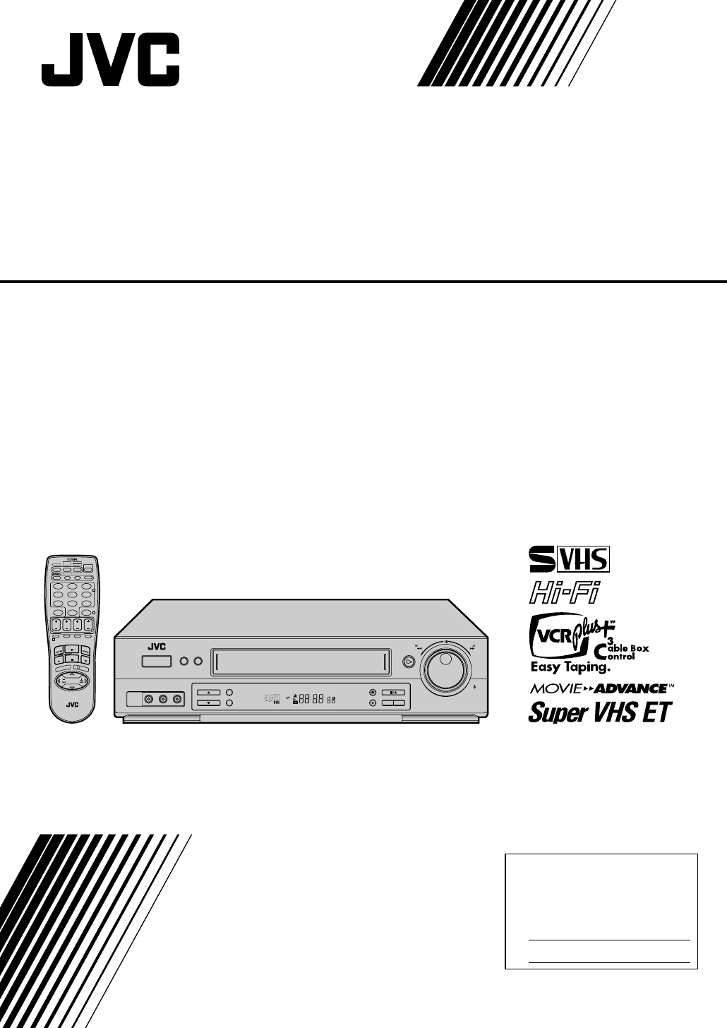
CONNECT VCR TO TV
3
The connection method you use depends on the type of
TV you have.
RF Connection
●
To Connect To A TV With NO AV Input Terminals . . .
a– Disconnect the TV antenna from the TV.
b– Connect the TV antenna cable to the ANTENNA
IN jack on the rear of the VCR.
c– Connect the supplied RF cable between the TV
OUT jack on the rear of the VCR and the TV’s
antenna terminal. Set TV on CH3 or CH4
corresponding to the CH3 – CH4 switch setting on
the back of the VCR.
AV Connection
●
To Connect To A TV With AV Input Terminals . . .
a– Connect the antenna, VCR and TV as shown in
the illustration.
b– Connect an Audio/Video Cable between the AUDIO
OUT and VIDEO OUT jacks on the rear of the VCR
and the AV IN jacks on the TV. Set your TV in video
input mode or A/V input mode. Refer to the TV
Instruction Manual.
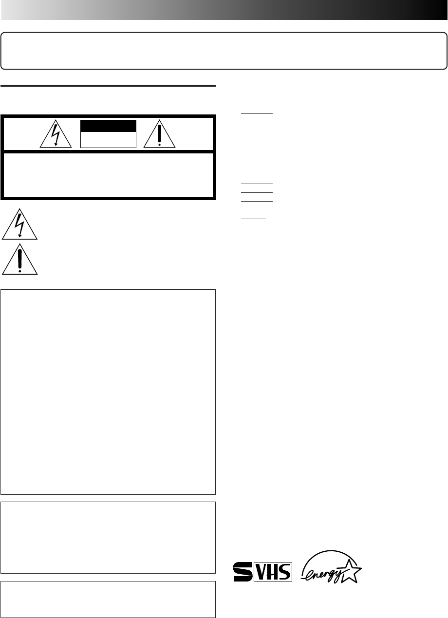
S-VIDEO Connection
●
If you have a TV with S-VIDEO input terminals, see
"S-VIDEO Connection" on page 7.
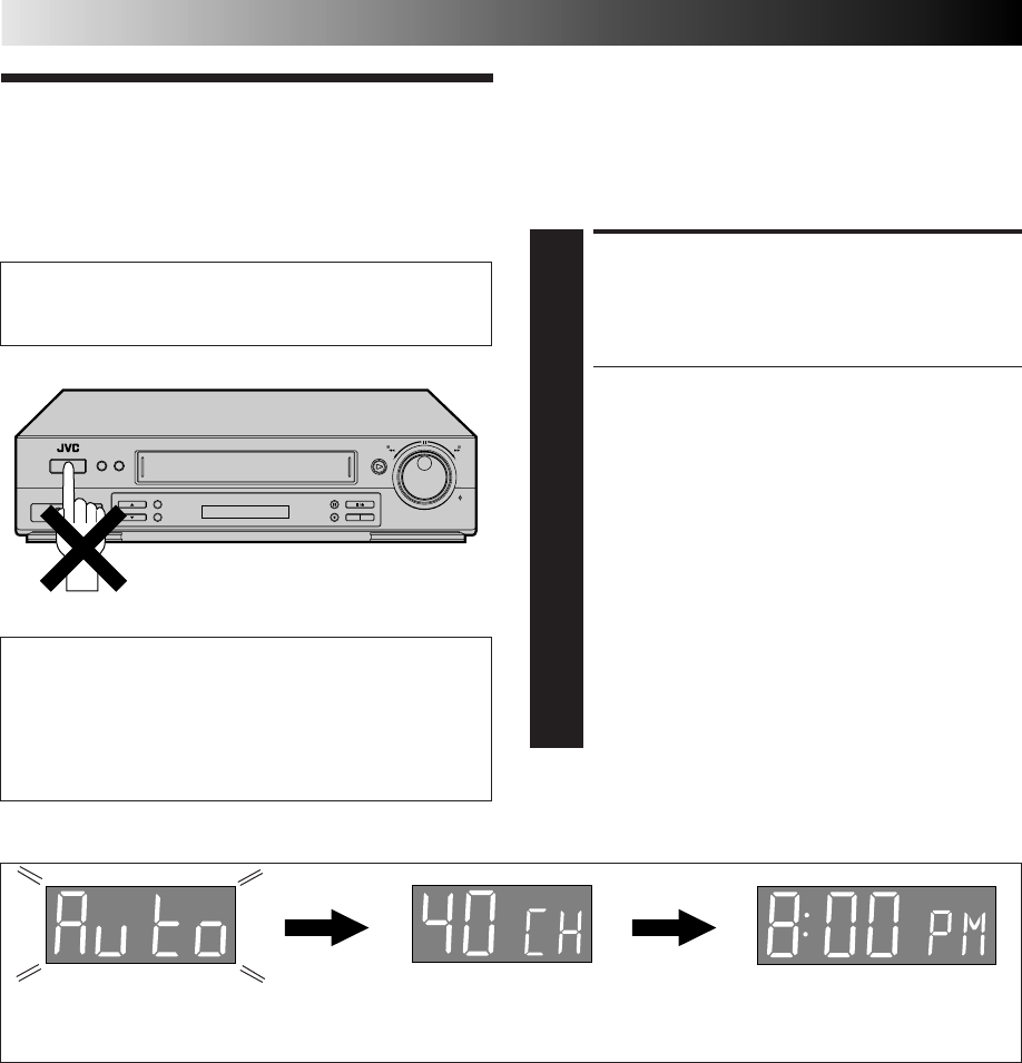
CONNECT VCR TO
POWER SOURCE
4
Connect the power plug to an AC outlet.
●The clock and tuner channels will automatically be
set when the antenna is connected and when the AC
is first connected to the VCR (Z pg. 8).
(If "Auto" or "CH" is displayed on the front display
panel before the VCR is powered on, the clock and
tuner channels are being set automatically. Wait for
the time to be displayed on the front display panel
before powering on the VCR.)
FINAL PREPARATION FOR
USE
5
Power on the VCR and if you have connected the VCR
to the TV using the RF connector, select the VCR
channel (3 or 4) by setting the switch on the rear of the
VCR as shown in the illustration.
You can now perform simple playback (Z pg. 22) or
simple recording (Z pg. 23).
NOTES:
●
The VCR channel is the channel on the TV which will display
the audio and video signals from the VCR. The VCR's CH3-
CH4 switch, on the back of the VCR, sets the VCR channel to
CH3 or CH4.
●
The CH3–CH4 switch is preset to the CH3 position.
Set to CH4 if CH3 is used for broadcasting in your area and
set the channel on the TV to correspond to the VCR's CH3–
CH4 switch setting.
●
If you have connected your VCR to the TV using the RF
connector, you may need to press the TV's CH UP and then CH
DOWN when switching between the TV and VCR input modes,
to maintain good picture quality.
●
Even if you are using AV cables to connect your VCR to your
TV, you must also connect it using the RF cable. This will
ensure that you can record one show while watching another
(
Z
pg. 34).
●
For full identification of the VCR's rear panel, refer to the
Index (REAR VIEW
Z
pg. 61).
Connections
Antenna or Cable
Flat Feeder
Coaxial Cable
AC Power Cord
Back of VCR
AC Outlet
75 ohm terminal
TV
Matching
Transformer
(Not supplied)
TV OUT
Audio/Video
Cable (supplied)
RF Cable
(supplied)
CH4
CH3
Back of VCR
ANTENNA IN
(Antenna or Cable input)
Basic Connections
EN 7
ANTENNA IN
CH4
CH3
REMOTE
PAUSE AV
COMPULINK
CABLE
BOX
VIDEO
AUDIO
VHF/UHF
L
(MONO)
R
OUT
TV
OUT IN
OUT
S VIDEO
IN
TV OUT
RF Cable (supplied)
Matching Transformer
(not supplied)
AC Power
Cord
Audio/Video Cable
(supplied)
TV
ANTENNA IN
(Antenna or Cable input)
Back of VCR
75 ohm terminal
AC Outlet
Antenna or Cable
Flat Feeder
Coaxial Cable
NOTES:
●
To make the most of the Super VHS picture performance we
recommend that you use the supplied S-VIDEO cable to
connect your VCR to a TV with an S-VIDEO input connector.
●
To operate the VCR with your TV using the S-VIDEO
connection, set your TV to the AV mode using the TV's
remote control.
You can also use the TV/VCR button on the VCR's remote
control to set your TV to the AV mode. (
Z
pg. 51)
S-VIDEO Connection
CONNECT VCR TO TV
a– Connect both the RF cable and the AV cables to the TV as
explained in step 3 of "Basic Connections" (Z pg. 6).
b– Connect the S-Video cable between the S-VIDEO OUT
jack on the rear of the VCR and the S-VIDEO IN jack on
the TV.
S-Video Cable
(supplied)
S VIDEO IN
S VIDEO OUT
8 EN
INITIAL SETTINGS
Plug & Play
The Plug & Play function sets the clock and tuner channels
automatically when power is first connected to the VCR. The
antenna cable must be connected for the Plug & Play function.
The time and date can be set automatically from clock setting
data that is transmitted by one of the regular TV broadcast
channels. We call this TV channel the “Host Channel” and it is
a PBS channel in your area.
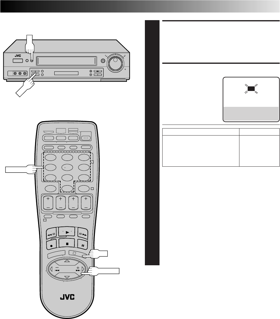
PLUG & PLAY SETUP
1
Connect the antenna cable to the VCR (Z pg. 6). Then
connect the VCR’s power plug to an AC outlet. Do not
power on the VCR. The clock and tuner channels will
be set automatically.
NOTES:
●
Auto clock set is performed first. The auto clock set
function scans all the channels received by your VCR
to find the Host Channel and then sets the clock.
"Auto" blinks on the front display panel during Auto
clock set.
●
Auto channel set is performed next. The auto channel
set function scans all the channels that are receivable
by your VCR. It then automatically assigns each
receivable channels to the CH
5∞
(+/–) buttons. It
skips non-receivable channels. During auto channel
set the channel numbers are displayed as they are
scanned and set.
●
When Plug & Play has been completed successfully the
correct time is displayed.
●
If an incorrect time or "– –:– –" appears on the display
panel, see "What To Do If Plug & Play Has Failed" on
next page.
ATTENTION
If you use a cable box, Plug & Play will not function; set
the clock and tuner channels manually. (Z pg.11 – 15)
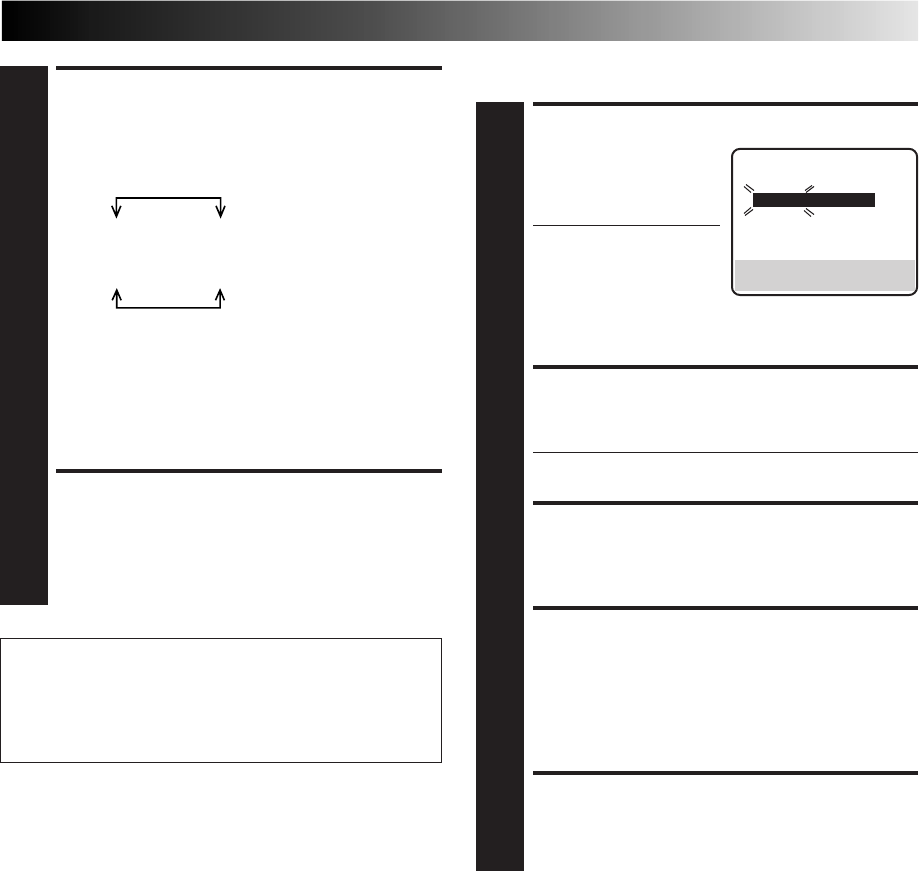
Auto Clock Set/Auto Tuner Set
IMPORTANT
●Don’t press any buttons on the VCR or remote while
Plug & Play is in progress.
●If you perform Plug & Play successfully, there’s no need to
perform the Clock (Z pg. 11) and Tuner (Z pg. 14)
procedures. If, however, you want to add or delete
channels, refer to “Add Or Delete A Channel” on page 15.
During Initial Auto Clock Set
"Auto" blinks. During Auto Channel Set
The channel numbers are displayed
as they are scanned and set.
* If an incorrect time or "– –:– –" appears on the display panel, see "What To Do If Plug & Play Has Failed" on next page.
Plug & Play Completed
The current time (including
AM/PM) is displayed.

EN 9
INFORMATION
●If "AUTO CLOCK" is set to "ON" at the Clock Set screen on page 12, the clock will be adjusted automatically by the host
channel every hour on the hour (except for 11:00 PM, midnight, 1:00 AM and 2:00 AM) by the incoming PBS channel clock
setting data. (This automatic clock adjustment can only be performed when the VCR’s power is turned off. The clock will be
adjusted on the hour based on the time displayed on the VCR, not on the actual real time.) The default setting of "AUTO
CLOCK" is "ON".
●If the memory backup fails, because of a power outage or because the AC was removed from the VCR, Plug & Play will be
performed when power is restored to the VCR.
What To Do If Plug & Play Has Failed
●If an incorrect time is displayed on the front display panel, you may be receiving the clock setting data of a PBS channel from
an adjacent time zone, or an incorrect PBS channel from a cable TV system. In this case, perform the Semi-Auto (Z pg. 12) or
Manual Clock Set (Z pg. 13) procedure. Auto channel set has already taken place and it need not be set again.
●If “- -:- -” appears on the display, your antenna cable may not be connected to the VCR or there may not be a Host PBS signal
available in your area. Ensure that the antenna cable is connected correctly. Then power on and power off the VCR; the Plug &
Play function will be automatically reactivated and "Auto" will be displayed on the VCR's front panel. If Plug & Play is not
performed but the antenna cable is connected correctly, perform the Manual Clock Set procedure (Z pg. 13). Auto channel
set has not yet taken place, so please also perform the “Set Receivable Channels” procedure (Z pg. 14).
10 EN
INITIAL SETTINGS (cont.)
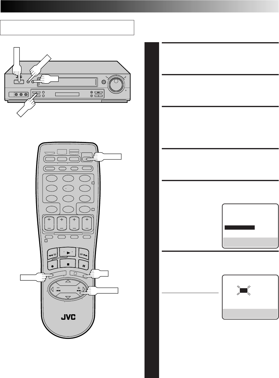
Language This VCR offers you the choice to view on-screen messages in
English, Spanish or French (not including messages superimposed
on the TV picture). Select the desired language using this
procedure. The default setting is "ENGLISH".
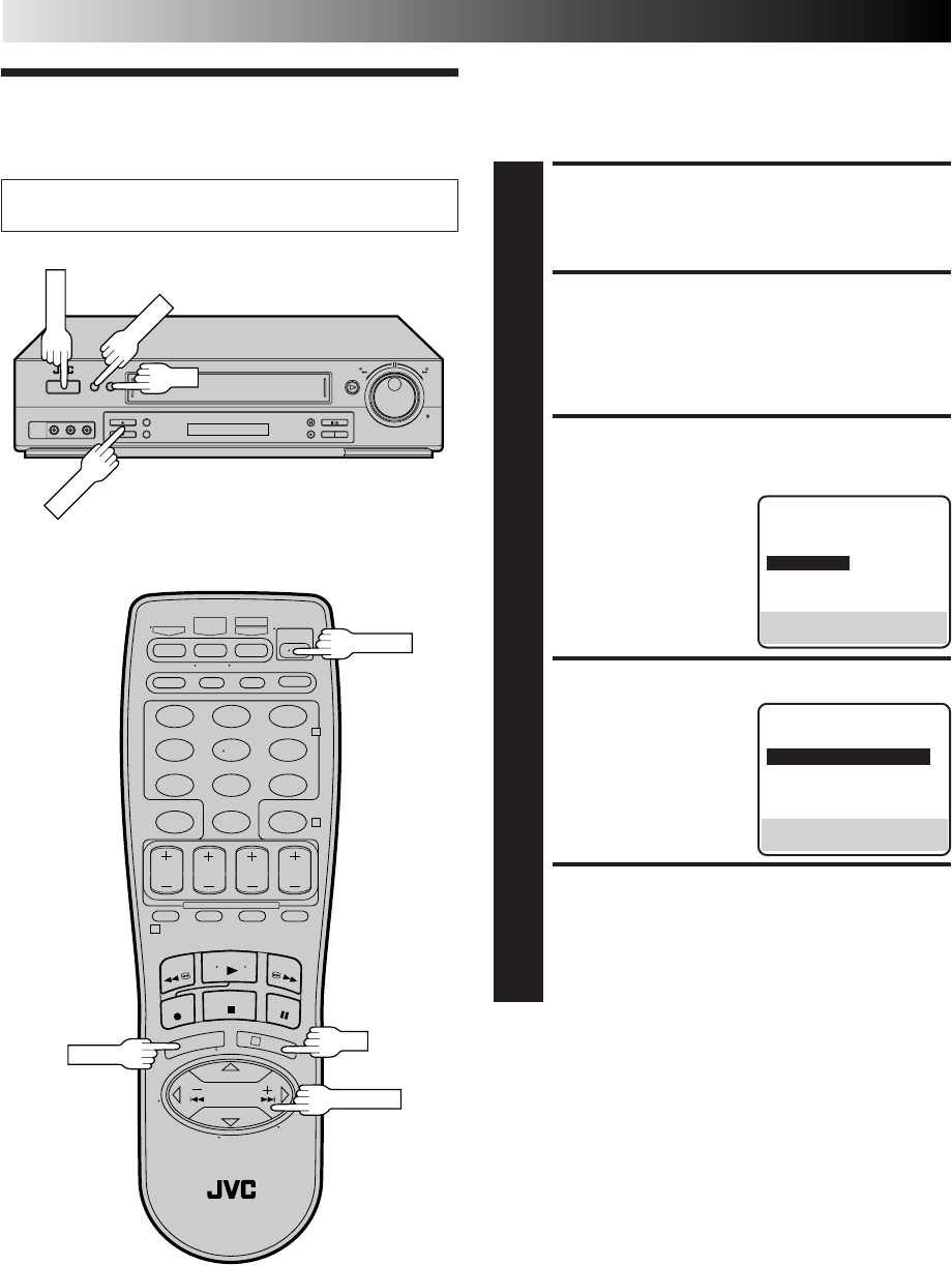
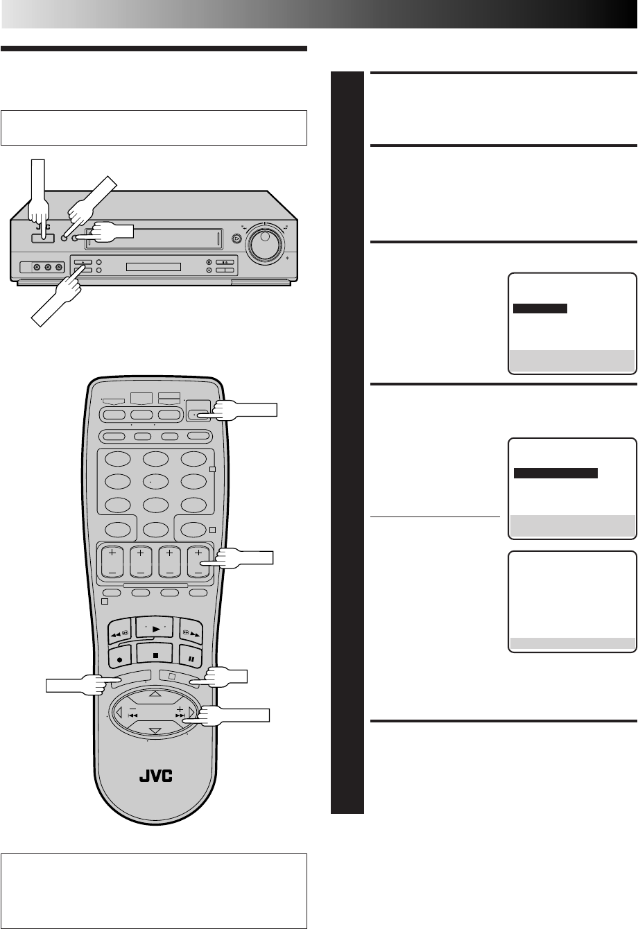
TURN ON THE VCR
1
Press POWER.
ACCESS MAIN MENU
SCREEN
2
Press MENU.
ACCESS INITIAL SET
SCREEN
3
At the Main Menu screen,
move the highlight bar
(arrow) to “INITIAL SET”
by pressing CH5∞ or
SHUTTLE PLUS %fi, then
press OK or SHUTTLE
PLUS .
SELECT LANGUAGE
4
Move the highlight bar
(arrow) to "LANGUAGE"
by pressing CH 5∞ or
SHUTTLE PLUS %fi, then
press OK or SHUTTLE
PLUS to select the
desired language.
RETURN TO NORMAL
SCREEN
5
Press MENU.
Turn on the TV and select the VCR channel 3 or 4 (or AV
mode).
%
MAIN MENU
FUNCTION SET
TUNER SET
=INITIAL SET
PRESS (5,∞), THEN (OK)
PRESS (MENU) TO END
%
INITIAL SET
CLOCK SET
=LANGUAGE ENGLISH
GUIDE CHANNEL SET
CABLE BOX SET
DBS RECEIVER SET
SELECT WITH (5,∞) AND (OK)
PRESS (MENU) TO END
POWER
123
456
789
0
2
4
1
3
POWER
OK
MENU
MENU
OK
SHUTTLE PLUS
CH5∞
EN 11
Clock
Perform clock setting only if the clock has not been set correctly
by the Plug & Play function or you use a cable box. Access the
Clock Set screen to perform the Semi-Auto or Manual clock
setting procedure. Each procedure starts from step 5.
If you use a cable box, set the clock manually. (Z pg. 13)
Turn on the TV and select the VCR channel 3 or 4 (or AV
mode). Preparation
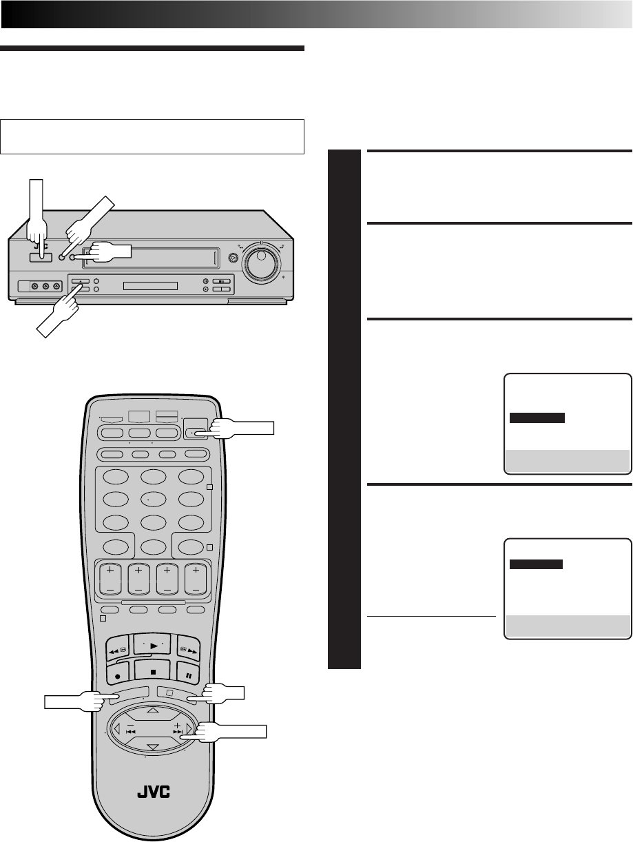
TURN ON THE VCR
1
Press POWER.
ACCESS MAIN MENU
SCREEN
2
Press MENU.
ACCESS INITIAL SET
SCREEN
3
At the Main Menu screen,
move the highlight bar
(arrow) to “INITIAL SET”
by pressing CH5∞ or
SHUTTLE PLUS %fi, then
press OK or SHUTTLE
PLUS .
ACCESS CLOCK SET
SCREEN
4
Move the highlight bar
(arrow) at the Initial Set
screen to “CLOCK SET” by
pressing SHUTTLE PLUS
%fi, then press OK or
SHUTTLE PLUS .
●"CABLE BOX USERS SET
CLOCK MANUALLY"
appears on the screen for about 5 seconds, then the
Clock Set screen appears.
%
%
MAIN MENU
FUNCTION SET
TUNER SET
=INITIAL SET
PRESS (5,∞), THEN (OK)
PRESS (MENU) TO END
INITIAL SET
=CLOCK SET
LANGUAGE ENGLISH
GUIDE CHANNEL SET
CABLE BOX SET
DBS RECEIVER SET
SELECT WITH (5,∞) AND (OK)
PRESS (MENU) TO END
POWER
123
456
789
0
2
4
1
3
POWER
CH
OK
MENU
MENU
OK
SHUTTLE PLUS
12 EN
INITIAL SETTINGS (cont.)
Semi-Auto
You can change the Host Channel/D.S.T. /Time Zone setting
manually.
SET AUTO CLOCK TO ON
5
At the Clock Set screen,
press OK or SHUTTLE
PLUS repeatedly to
move the highlight bar to
"AUTO CLOCK" and press
CH 5∞ or SHUTTLE PLUS
%fi to set to "ON".
a– To select the Host
Channel — go to step 6
b– To select the D.S.T. mode — go to step 7
c– To select the Time Zone — go to step 8
NOTE:
The time that has been set previously will be erased
when "AUTO CLOCK", "HOST CH", "D.S.T." or "TIME
ZONE" setting is changed.
SELECT HOST CHANNEL
6
You can either select "AUTO" or enter a PBS channel
number. Move the highlight bar to "HOST CH" by
pressing OK or SHUTTLE PLUS , then press CH 5∞
or SHUTTLE PLUS %fi to set to "AUTO" or the desired
PBS channel number.
NOTE:
There are some PBS channels that do not transmit clock
setting data.
SELECT D.S.T. MODE
7
You have three choices:
a– Select "AUTO" and the adjustment to your VCR's
clock will be made according to the incoming signal
from the host channel.
b– Select "ON" and the adjustment will be made based
on the clock itself.
c– Select "OFF" if Daylight Saving Time does not apply
to you.
Move the highlight bar to "D.S.T." by pressing OK or
SHUTTLE PLUS , then press CH 5∞ or SHUTTLE
PLUS %fi to select the desired mode.
%
**AUTO DAYLIGHT SAVING TIME
This function enables automatic adjustment of the VCR’s
clock at the start and end of Daylight Saving Time.
With Auto DST activated, . . .
. . . on the first Sunday of April at 2:00 AM, the clock is
adjusted to 3:00 AM.
. . . on the last Sunday of October at 2:00 AM, the clock is
adjusted to 1:00 AM.
%
%
CLOCK SET
TIME DATE YEAR
1:00PM 12/24 98 THU
AUTO CLOCK : ON
HOST CH : AUTO (CATV)
D.S.T. : AUTO
TIME ZONE : AUTO
PRESS (5,∞), THEN (OK)
PRESS (MENU) TO END
123
456
789
0
2
4
1
3
CH
OK
MENU
MENU
OK
SHUTTLE PLUS
EN 13
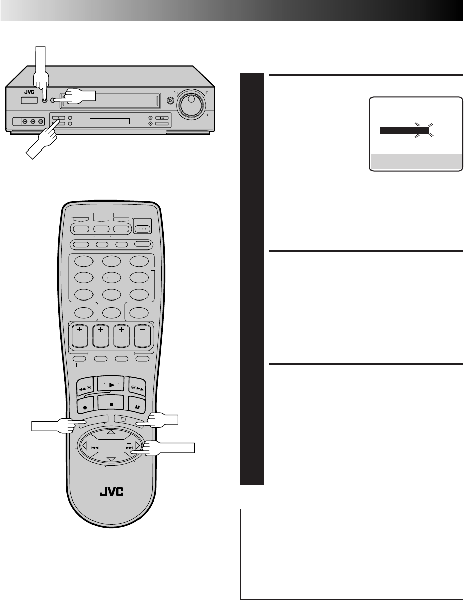
SET TIME
5
Press CH 5∞ or SHUTTLE
PLUS %fi until the desired
time appears, then press
OK or SHUTTLE PLUS .
●Press and hold CH 5∞
or SHUTTLE PLUS %fi
to change the time by
30-minute increments.
●When the time is entered manually, "AUTO CLOCK"
will be automatically set to "OFF", and "HOST CH"
and "TIME ZONE" will disappear.
SET DATE
6
Press CH 5∞ or SHUTTLE PLUS %fi until the desired
date appears, then press OK or SHUTTLE PLUS .
●Press and hold CH 5∞ or SHUTTLE PLUS %fi to
change the date by 15-day increments.
SET YEAR
7
Press CH 5∞ or SHUTTLE PLUS %fi until the desired
year appears, then press OK or SHUTTLE PLUS twice.
SELECT D.S.T. MODE
8
Press CH 5∞ or SHUTTLE PLUS %fi to select the
desired mode.
a– Set to "ON" so that the adjustment to your VCR's
clock will be made on the clock itself.
b– Set to "OFF" if Daylight Saving Time does not apply
to you.
START CLOCK
9
Press MENU and normal screen appears.
Manual
%
%
To Make Corrections
Press OK or SHUTTLE PLUS until the item you want to
change blinks, then press CH 5∞ or SHUTTLE PLUS %fi.
%
SELECT TIME ZONE
8
You can select the time zone automatically or manually.
Move the highlight bar to "TIME ZONE" by pressing OK
or SHUTTLE PLUS , then press CH 5∞ or SHUTTLE
PLUS %fi to select "AUTO" or the desired time zone.
AUTO ATLANTIC
HAWAII EASTERN
ALASKA CENTRAL
PACIFIC MOUNTAIN
NOTE:
If an incorrect time is displayed by the Plug & Play
function, you may be receiving the clock setting data of
a PBS channel from an adjacent time zone or from an
incorrect PBS channel from a cable TV system. If you
selected "AUTO" for the host channel in step 6, be sure
to select the correct time zone manually.
RETURN TO NORMAL
SCREEN
9
Press MENU.
IMPORTANT
Turn the VCR off after performing the Semi-Auto Clock Set
procedure. "Auto" will appear on the front display panel
when the clock is being set. The current time will appear
automatically when the clock is set.
%
CLOCK SET
TIME DATE YEAR
– –:– –AM 1/ 1 98
AUTO CLOCK : ON
HOST CH : AUTO (CATV)
D.S.T. : AUTO
TIME ZONE : AUTO
PRESS (5,∞), THEN (OK)
PRESS (MENU) TO END
%
14 EN
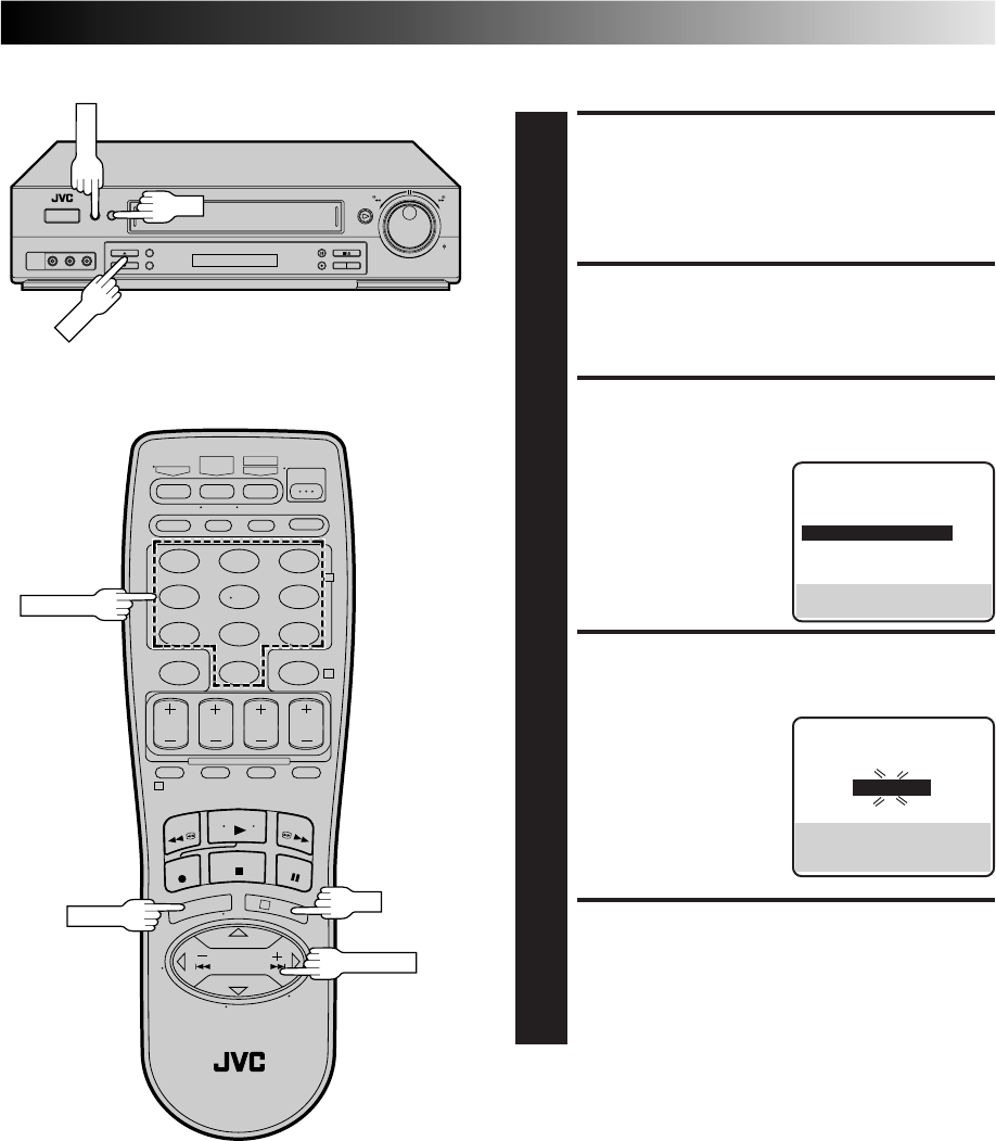
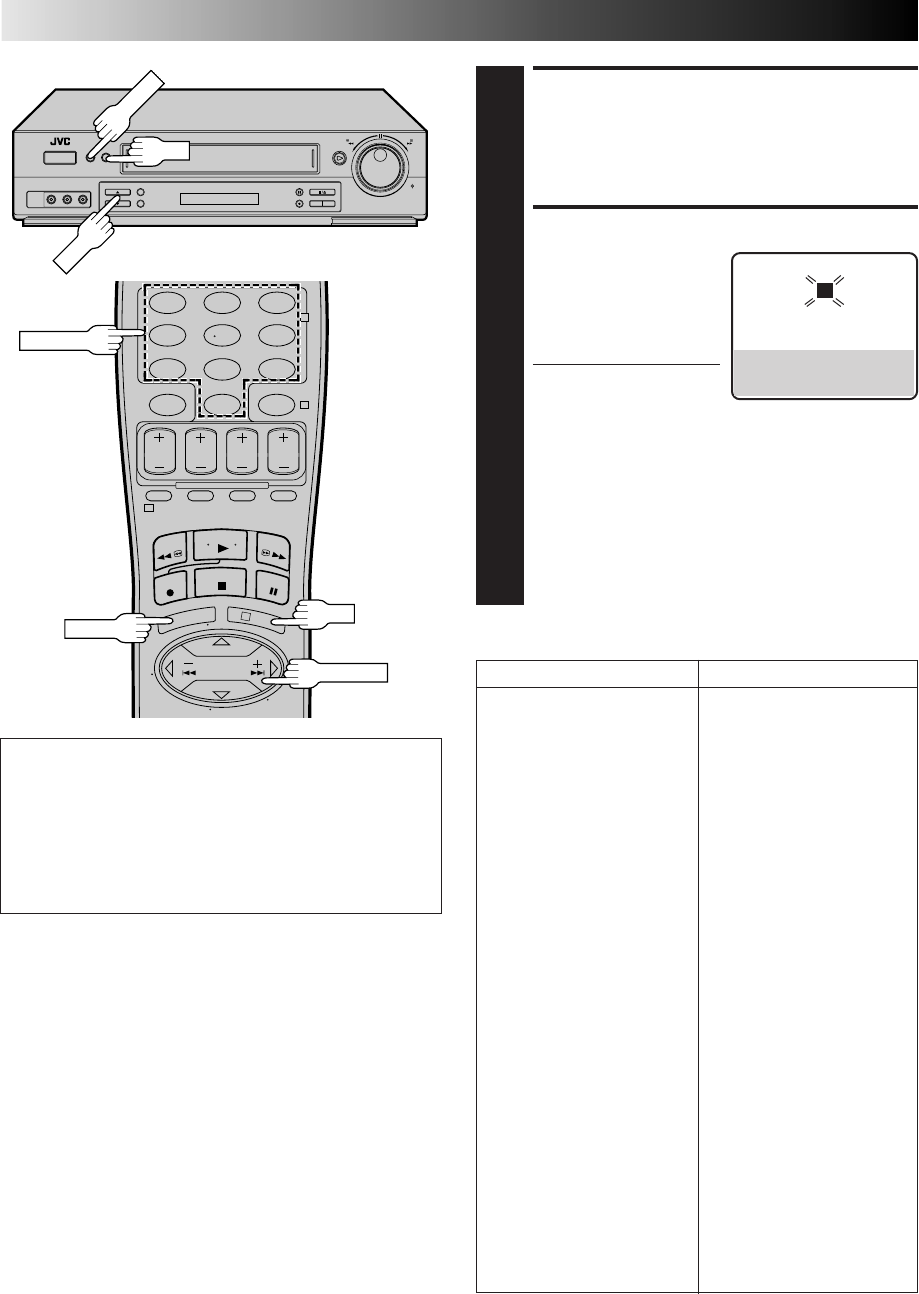
Tuner Set Receivable Channels
TURN ON THE VCR
1
Press POWER.
ACCESS MAIN MENU
SCREEN
2
Press MENU.
ACCESS TUNER SET SCREEN
3
Move the highlight bar
(arrow) to "TUNER SET" by
pressing CH5∞ or
SHUTTLE PLUS %fi, then
press OK or SHUTTLE
PLUS .
PERFORM AUTO CHANNEL
SET
4
Move the highlight bar
(arrow) to "AUTO CHAN-
NEL SET" by pressing
CH5∞ or SHUTTLE PLUS
%fi, then press OK or
SHUTTLE PLUS .
●Receivable channels in
your area are
automatically assigned to
the CH5∞ (+/–) buttons,
and non-receivable
channels are skipped.
NOTES:
●
At the end of Auto
Channel Set, “SCAN
COMPLETED” appears
on screen.
●
If the scan was unsuccessful, “SCAN COMPLETED–
NO SIGNAL” appears on screen. Check the
connections and start again.
RETURN TO NORMAL
SCREEN
5
Press MENU.
INITIAL SETTINGS (cont.)
%
%
INFORMATION
The VCR detects the band (TV or CATV) and selects the
correct band automatically during Auto Channel Set.
The selected band will be displayed on the right side of
"BAND" on the Tuner Set screen.
Turn on the TV and select the VCR channel 3 or 4 (or AV
mode).
MAIN MENU
FUNCTION SET
=TUNER SET
INITIAL SET
PRESS (5,∞), THEN (OK)
PRESS (MENU) TO END
AUTO CHANNEL SET
SCANNING...
PRESS (MENU) TO END
TUNER SET
BAND CATV
=AUTO CHANNEL SET
MANUAL CHANNEL SET
SELECT WITH (5,∞) AND (OK)
PRESS (MENU) TO END
POWER
123
456
789
0
2
4
1
3
POWER
OK
MENU
MENU
OK
SHUTTLE PLUS
CH+/–
CH5∞
EN 15
Add Or Delete A Channel
ACCESS MAIN MENU
SCREEN
1
Press MENU.
ACCESS TUNER SET SCREEN
2
Move the highlight bar (arrow) to "TUNER SET" by
pressing CH5∞ or SHUTTLE PLUS %fi, then press OK
or SHUTTLE PLUS .
ACCESS MANUAL
CHANNEL SET SCREEN
3
Move the highlight bar
(arrow) to "MANUAL
CHANNEL SET" by
pressing CH5∞ or
SHUTTLE PLUS %fi, then
press OK or SHUTTLE
PLUS .
ADD OR SKIP DESIRED
CHANNEL
4
Input the channel number
using the NUMBER keys or
by pressing CH5∞ or
SHUTTLE PLUS %fi, then
press OK or SHUTTLE
PLUS to set to "ADD" or
"SKIP" as required. Repeat
for each channel you want
to add or skip.
RETURN TO NORMAL
SCREEN
5
Press MENU.
%
%%
TUNER SET
BAND CATV
AUTO CHANNEL SET
=MANUAL CHANNEL SET
SELECT WITH (5,∞) AND (OK)
PRESS (MENU) TO END
MANUAL CHANNEL SET
(CATV)
CH 45 ADD
PRESS NUMBER KEY (0–9)
OR (5,∞), THEN (OK)
PRESS (MENU) TO END
123
456
789
0
2
4
1
3
CH
OK
MENU
MENU
OK
SHUTTLE PLUS
NUMBER
16 EN
INITIAL SETTINGS (cont.)
This procedure is required if you receive your TV channels
through a cable box (descrambler). The Controller allows the
VCR to automatically switch the cable box channel during
timer-recording. The Controller is effective for recording shows
that have been programmed using VCR Plus+ (Z pg. 38) or
Express Timer Programming (Z pg. 42).
Cable Box
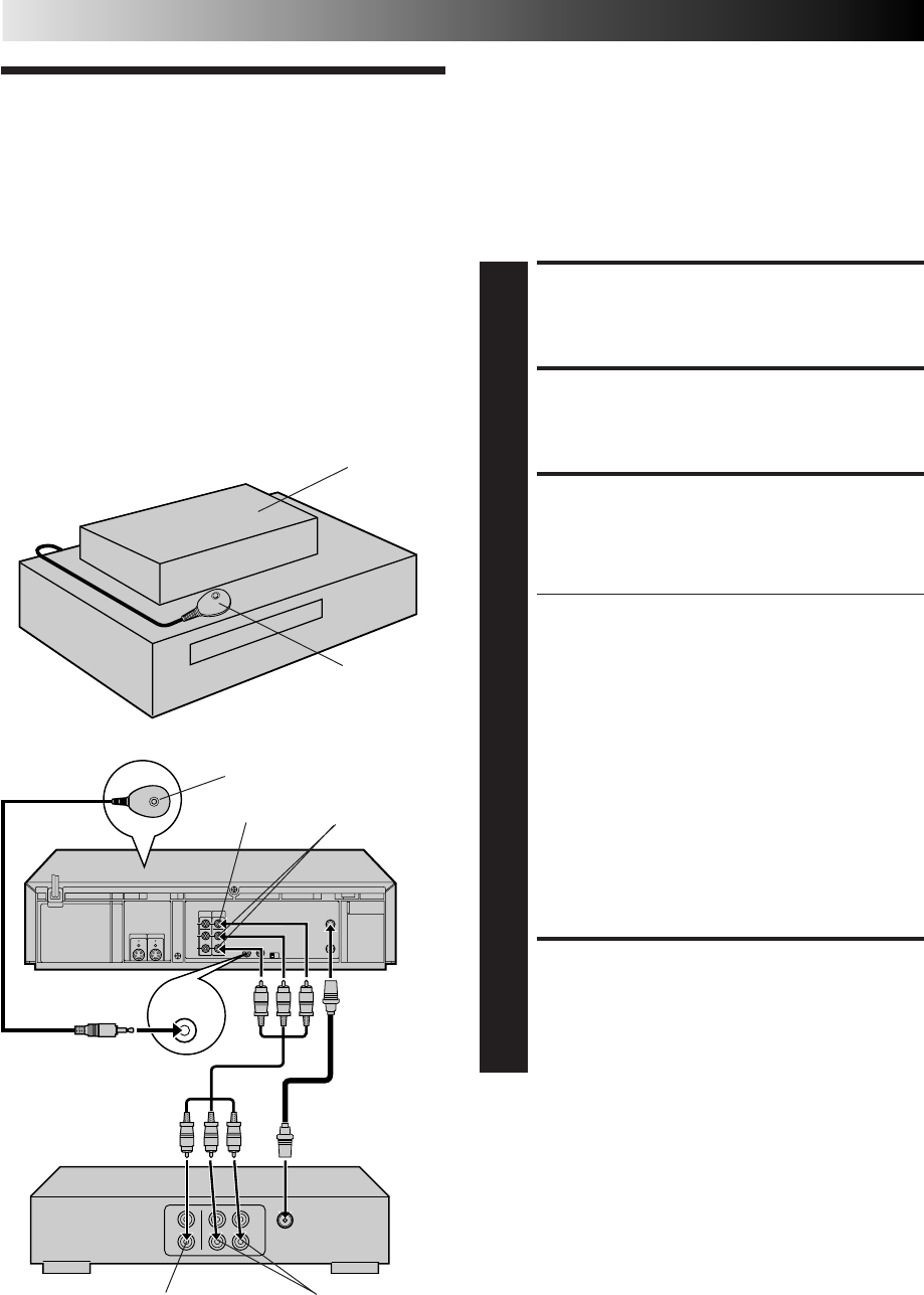
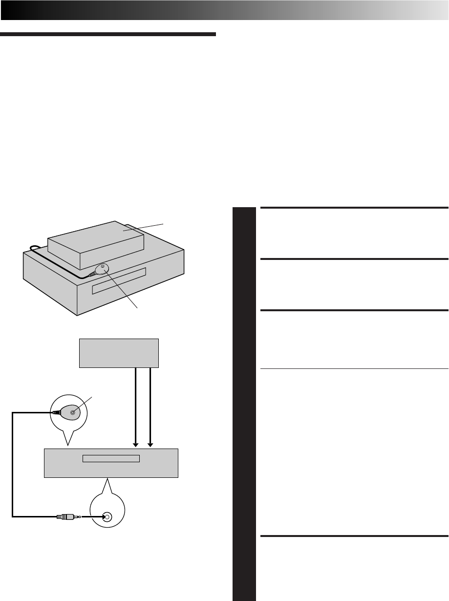
Control Situate And Connect
Controller
SITUATE CONTROLLER
1
Place the Controller so that the path between its
transmitter and the cable box’s remote sensor is
unobstructed.
ATTACH CONTROLLER
2
Fasten securely using the supplied adhesive strip.
CONNECT CABLE BOX TO
VCR
3
The connection method depends on the type of cable
box you have.
If your cable box has AUDIO and VIDEO OUT
connectors . . .
. . . connect them to the AUDIO and VIDEO IN
connectors on your VCR. Set the VCR to channel "L-1"
for the rear AUDIO and VIDEO IN connectors, or
channel "F-1" for the front AUDIO and VIDEO IN
connectors to use the cable box.
If your cable box doesn’t have AUDIO and VIDEO
OUT connectors . . .
. . . connect the antenna output connector on the cable
box to the ANTENNA IN connector on the rear of your
VCR.
Set the VCR tuner to the same channel as the cable box
RF output (see page 17 also).
NOTE:
When connecting your cable box refer to its instruction
manual.
CONNECT CONTROLLER
TO VCR
4
Connect to the CABLE BOX connector on your VCR.
Suggested Location
Place the cable box on top of the VCR. Attach the VCR's
Controller to the top of the VCR with the Controller’s transmitter
pointed towards the cable box’s remote sensor.
ATTENTION:
The Controller can also control a DBS receiver. If both a cable
box and a DBS receiver are used, position the controller so its
signal reaches the remote control sensors of both the cable box
and DBS receiver.
About Your Cable Box
This VCR has two separate methods to control your Cable Box.
●
The VCR's Wireless Remote Control Unit can control your
Cable Box.
This eliminates the need for a separate Cable Box Remote
Control Unit.
●
The VCR's Controller can also control your Cable Box.
This allows the VCR to change your Cable Box's channel
number during timer recording.
Each method must be set up separately. To set up the VCR's
Remote Control unit, refer to page 52. To set up the Controller
go to page 17.
CABLE
BOX
Cable box
Cable box
Your VCR Controller
(suggested
locations)
Controller
Transmitter
Your VCR
AUDIO IN
VIDEO IN
VIDEO OUT AUDIO OUT
Connected to
ANTENNA IN
Audio/Video cable
(supplied)
EN 17
Turn on the TV and select the VCR channel 3 or 4 (or AV
mode). Set Cable Box Output
Channel & Cable Box Brand
TURN ON CABLE BOX
1
Select a channel other than channel 9 on your cable
box.
TURN ON THE VCR
2
Press POWER.
ACCESS MAIN MENU
SCREEN
3
Press MENU.
ACCESS INITIAL SET SCREEN
4
Press CH5∞ or SHUTTLE PLUS %fi to move the
highlight bar (arrow) to “INITIAL SET”, then press OK or
SHUTTLE PLUS .
ACCESS CABLE BOX SET
SCREEN
5
Press CH5∞ or SHUTTLE
PLUS %fi to move the
highlight bar (arrow) to
“CABLE BOX SET”, then
press OK or SHUTTLE
PLUS .
SELECT CABLE BOX
OUTPUT CHANNEL
6
Your selection depends on
how your cable box is
connected to your VCR.
If your cable box is
connected to your VCR
using an RF connection . . .
. . . press CH 5∞ or
SHUTTLE PLUS %fi until
the channel number representing the cable box’s output
(CH2 – CH9) appears on the screen.
If your cable box is connected to your VCR's FRONT
AUDIO/VIDEO IN connectors . . .
. . . press CH 5∞ or SHUTTLE PLUS %fi until "ON F-1
(FRONT)" appears on the screen.
If your cable box is connected to your VCR’s REAR
AUDIO/VIDEO IN connectors . . .
. . . press CH 5∞ or SHUTTLE PLUS %fi until "ON L-1
(REAR)" appears on the screen.
%
%
CONTINUED ON NEXT PAGE
INITIAL SET
CLOCK SET
LANGUAGE ENGLISH
GUIDE CHANNEL SET
=CABLE BOX SET
DBS RECEIVER SET
SELECT WITH (5,∞) AND (OK)
PRESS (MENU) TO END
CABLE BOX SET
OFF
PRESS (5,∞), THEN (OK)
PRESS (MENU) TO END
POWER
123
456
789
0
2
4
1
3
POWER
CH
OK
MENU
MENU
OK
SHUTTLE PLUS
18 EN
INITIAL SETTINGS (cont.)
ACCESS CABLE BOX
BRAND SET SCREEN
7
Press OK.
ENTER CABLE BOX BRAND
8
Press the appropriate
NUMBER keys to enter the
Cable Box Code from the
CABLE BOX BRAND LIST
shown below, then press
OK.
●If the cable box’s
channel changes to 9,
setting is complete. Press OK and "CABLE BOX
CONTROL IS ON" appears on the screen for about 5
seconds, then it returns to the normal screen.
●If the cable box's channel does not change to 9, press
CH 5∞ or SHUTTLE PLUS %fi to move the highlight
bar (arrow) to "NO", then press OK. By entering
another code, repeat step 8 until the cable box’s
channel changes to 9.
●If the channel does not change after going through all
the code numbers listed for your model of cable box,
then try all the other numbers between 1 and 25.
CABLE BOX BRAND LIST
BRAND CODE
ARCHER 1, 5, 17
CABLETENNA 1, 17
CABLEVIEW 15, 16, 17, 21, 25
CITIZEN 15, 16, 17, 21, 25
CURTIS 2
DIAMOND 1, 17
EASTERN 19
GC BRAND 15, 16, 17, 21, 25
GEMINI 15
GENERAL INSTRUMENTS 1, 4, 6, 11, 12, 15
HAMLIN 10, 18, 19, 23
JASCO 15
JERROLD 1, 4, 6, 11, 12, 15
NOVAVISION 2
OAK 7, 20
PANASONIC 13, 14
PULSER 15, 16, 17, 21, 25
RCA 13, 14
REGAL 10, 18, 19, 23
REGENCY 19
REMBRANDT 1, 16, 17
SAMSUNG 5, 16, 24
SCIENTIFIC ATLANTA 2
SIGMA 7, 20
SL MARX 5, 16, 17, 24, 25
SPRUCER 13, 14
STARGATE 5, 15, 16, 17, 21, 24, 25
TELEVIEW 5, 16, 24
TOCOM 1, 4, 16
UNIKA 1, 17
UNIVERSAL 16, 17, 25
VIDEOWAY 3, 9, 22
ZENITH 3, 9, 22
NOTES:
●
Although the supplied Controller is compatible with many
different cable box brands, it is possible that it will not work
with your cable box.
●
If your cable box doesn’t respond to any code between 1 and
25, you can’t use the Controller to change cable box
channels. In this case, make sure to leave the cable box
turned on and tuned to the proper channel before the
scheduled start of timer recording.
Please contact your cable company about the possibility of
exchanging your current cable box with one that is compatible
with your VCR.
●
The VCR can only change the cable box channel through the
Controller during timer recording.
●
If your cable box is one that can’t be operated with a remote
control (because it has no remote sensor), you can’t use the
Controller to change its channels. Make sure to leave the
cable box turned on and tuned to the proper channel before
the scheduled start of timer recording.
●
If the VCR's memory backup expires because of a power
failure, set the cable box output channel and brand again.
●
For customers in U.S.A.: If you are unable to set the
Controller, please contact JVC toll free at 1-800-252-5722.
When the VCR's clock has not been set (with AUTO
CLOCK set to ON), if you press OK in step 7, "CABLE
BOX USERS SET CLOCK MANUALLY" will be displayed
on the screen for about 5 seconds, then the Clock Set
screen will appear; perform the manual clock setting
procedure on page 13. If you press MENU after the clock
has been set, the Cable Box Brand Set screen appears.
INFORMATION
CABLE BOX BRAND SET
1
PRESS NUMBER KEY (0–9)
THEN (OK) TO TEST
PRESS (MENU) TO END
MENU
123
456
789
0
2
4
1
3
CH
OK
OK
MENU
NUMBER
SHUTTLE PLUS
EN 19
The following procedure is required if you receive satellite channels
through a DBS (Direct Broadcast Satellite) Receiver. The Controller
allows the VCR to automatically switch the DBS Receiver's channels
during timer recording.
NOTES:
●
The VCR can automatically change the DBS Receiver channels
using the controller when the VCR has been programmed using
Express Timer Programming (
Z
pg. 42).
Because satellite programming does not use PlusCode; the
Controller can not change the DBS Receiver channels during
VCR Plus+ Timer Recording.
●
If a cable box is also used it is recommended that you
connect the DBS receiver to your VCR's A/V inputs and the
cable box to your VCR's antenna input.
Situate And Connect
Controller
DBS Receiver
Control
Suggested Location
Place the DBS (Direct Broadcast Satellite) receiver on top of the
VCR. Attach the VCR's Controller to the top of the VCR with the
Controller’s transmitter pointed towards the DBS receiver's
remote sensor.
ATTTNTION:
The Controller can also control a cable box. If both a DBS
receiver and a cable box are used, position the controller so its
signal reaches the remote control sensors of both the DBS
receiver and cable box.
About Your DBS Receiver
This VCR has two separate methods to control your DBS Receiver.
●
The VCR's Wireless Remote Control Unit can control your
DBS Receiver.
This eliminates the need for a separate DBS Receiver Remote
Control Unit.
●
The VCR's Controller can also control your DBS Receiver.
This allows the VCR to change your DBS receiver's channel
number during timer recording.
Each method must be set up separately. To set up the VCR's
Remote Control unit, refer to page 53. To set up the Controller
go to page 20.
CABLE
BOX
DBS receiver
Controller
(suggested locations)
Your VCR
DBS receiver
Controller
Transmitter
Connected
to VIDEO/
AUDIO IN
Your VCR
Connected to
ANTENNA IN
SITUATE CONTROLLER
1
Place the Controller so that the path between its
transmitter and the DBS receiver's remote sensor is
unobstructed.
ATTACH CONTROLLER
2
Fasten securely using the supplied adhesive strips.
CONNECT DBS RECEIVER
TO VCR
3
The connection method depends on the type of DBS
receiver you have.
If your DBS receiver has AUDIO and VIDEO OUT
connectors . . .
. . . connect them to the AUDIO and VIDEO IN
connectors on your VCR. Set the VCR to channel "L-1"
for the rear AUDIO and VIDEO IN connectors, or
channel "F-1" for the front AUDIO and VIDEO IN
connectors to use the DBS receiver.
If your DBS receiver doesn’t have AUDIO and VIDEO
OUT connectors . . .
. . . connect the antenna output connector on the DBS
receiver to the ANTENNA IN connector on the rear of
your VCR.
Set the VCR's tuner to the same channel as the DBS
receiver's RF output. (See page 20 also.)
NOTE:
When connecting your DBS receiver refer to its
instruction manual.
CONNECT CONTROLLER
TO VCR
4
Connect to the CABLE BOX connector on your VCR.
20 EN
INITIAL SETTINGS (cont.)
Set DBS Receiver Output
Channel & DBS Receiver
Brand
Turn on the TV and select the VCR channel 3 or 4 (or AV
mode).
TURN ON DBS RECEIVER
1
Select a channel other than channel 55, 100 or 205 on
your DBS receiver.
TURN ON THE VCR
2
Press POWER.
●Set the VCR to the channel (3 or 4 or F-1 or L-1) on
which the signals from the DBS receiver are received.
ACCESS MAIN MENU
SCREEN
3
Press MENU.
ACCESS INITIAL SET
SCREEN
4
Press CH5∞ or SHUTTLE PLUS %fi to move the
highlight bar (arrow) to “INITIAL SET”, then press OK or
SHUTTLE PLUS .
ACCESS DBS RECEIVER SET
SCREEN
5
Press CH5∞ or SHUTTLE
PLUS %fi to move the
highlight bar (arrow) to
“DBS RECEIVER SET”, then
press OK or SHUTTLE
PLUS .
SELECT DBS RECEIVER
OUTPUT CHANNEL
6
Your selection depends on
how your DBS receiver is
connected to your VCR.
If your DBS receiver is
connected to your VCR
using an RF connection . . .
. . . press CH 5∞ or
SHUTTLE PLUS %fi until
the channel number
representing the DBS receiver's output (CH3 – CH4)
appears on the screen.
If your DBS receiver is connected to your VCR's
FRONT AUDIO/VIDEO IN connectors . . .
. . . press CH 5∞ or SHUTTLE PLUS %fi until "ON F-1
(FRONT)" appears on the screen.
If your DBS receiver is connected to your VCR’s REAR
AUDIO/VIDEO IN connectors . . .
. . . press CH 5∞ or SHUTTLE PLUS %fi until "ON L-1
(REAR)" appears on the screen.
%
%
INITIAL SET
CLOCK SET
LANGUAGE ENGLISH
GUIDE CHANNEL SET
CABLE BOX SET
=DBS RECEIVER SET
SELECT WITH (5,∞) AND (OK)
PRESS (MENU) TO END
DBS RECEIVER SET
OFF
PRESS (5,∞), THEN (OK)
PRESS (MENU) TO END
POWER
123
456
789
0
2
4
1
3
POWER
CH
OK
MENU
MENU
OK
SHUTTLE PLUS
EN 21
123
456
789
0
2
4
1
3
NUMBER
ACCESS DBS RECEIVER
BRAND SET SCREEN
7
Press OK.
SET DBS RECEIVER BRAND
8
Press the appropriate
NUMBER keys to enter the
DBS Receiver Code from
the following list, then
press OK.
●After OK is pressed, the program currently received
through the DBS receiver will appear for about 10
seconds.
●If the DBS receiver's channel changes to the channel
listed below for your brand of DBS receiver, setting is
complete. Press OK and "DBS RECEIVER CONTROL
IS ON" appears on the screen for about 5 seconds,
then it returns to the normal screen.
JVC [ 100
ECHOSTAR [ 100
PRIMESTAR [ 55
SONY [ 205
RCA [ 205
●If the DBS receiver's channel does not change as
shown above, press CH 5∞ or SHUTTLE PLUS %fi
to move the highlight bar (arrow) to "NO", then press
OK. Re-enter the correct code.
BRAND CODE
JVC (DISH Network) 51
ECHOSTAR (DISH Network) 51
PRIMESTAR 50
SONY (DSS) 41
RCA (DSS) 40
NOTES:
●
It is possible that the Controller will not work with all types of
DBS receiver.
●
If your DBS receiver doesn’t respond to the code, you can’t
use the Controller to change satellite channels. In this case,
make sure to leave the DBS receiver turned on and tuned to
the proper channel before the scheduled start of timer
recording.
●
The VCR can only change the satellite channel through the
Controller during timer recording.
●
If your DBS receiver is one that can’t be operated with a
remote control (because it has no remote sensor), you can’t
use the Controller to change its channels. Make sure to leave
the DBS receiver turned on and tuned to the proper channel
before the scheduled start of timer recording.
●
For customers in U.S.A.: If you are unable to set the Control-
ler, please contact JVC toll free at 1-800-252-5722.
DBS RECEIVER BRAND SET
4 0
PRESS NUMBER KEY (0–9)
THEN (OK) TO TEST
PRESS (MENU) TO END
CH
OK
OK
SHUTTLE PLUS
22 EN
SIMPLE PLAYBACK AND RECORDING
Simple
Playback
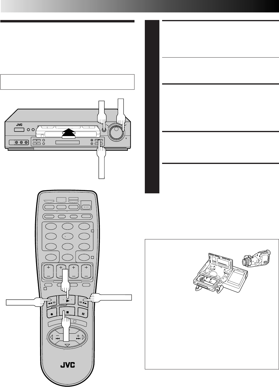
LOAD A CASSETTE
1
Make sure the window side is up, the rear label side is
facing you and the arrow on the front of the cassette is
pointing towards the VCR. Don’t apply too much
pressure when inserting.
●The VCR’s power comes on automatically.
●The counter is automatically reset to "0:00:00".
●If the cassette's record safety tab has been removed,
playback begins automatically.
FIND PROGRAM START
POINT
2
If the tape is advanced past the start point, press REW
or turn the SHUTTLE ring to the left and release it.
To go forward, press FF or turn the SHUTTLE ring to the
right and release it.
START PLAYBACK
3
Press PLAY. "VIDEO CALIBRATION" appears on the
screen (when VIDEO CALIBRATION is set to "ON"
Z pg. 32).
STOP PLAYBACK
4
Press STOP or STOP/EJECT. Then press STOP/EJECT
to remove the cassette.
Turn on the TV and select the VCR channel 3 or 4 (or AV
mode).
123
456
789
0
2
4
1
3
STOP/EJECT
PLAY
PLAY
REW (Rewind)
FF (Fast-Forward)
STOP
Usable cassettes
Full-Size VHS
T-30 (ST-30**)
T-60 (ST-60**)
T-90
T-120 (ST-120**)
T-160 (ST-160**)
ST-210**
Compact VHS*
TC-20 (ST-C20**)
TC-30 (ST-C30**)
TC-40 (ST-C40**)
* Compact VHS camcorder recordings can be played on
this video recorder. Simply place the recorded cassette
into a VHS Cassette Adapter and it can be used just like
any full-sized VHS cassette.
** This VCR can record on regular VHS and Super VHS
cassettes. While only VHS signals can be recorded on
regular VHS cassettes, both VHS and Super VHS signals
can be recorded and played back using Super VHS
cassettes.
SHUTTLE
EN 23
Simple
Recording
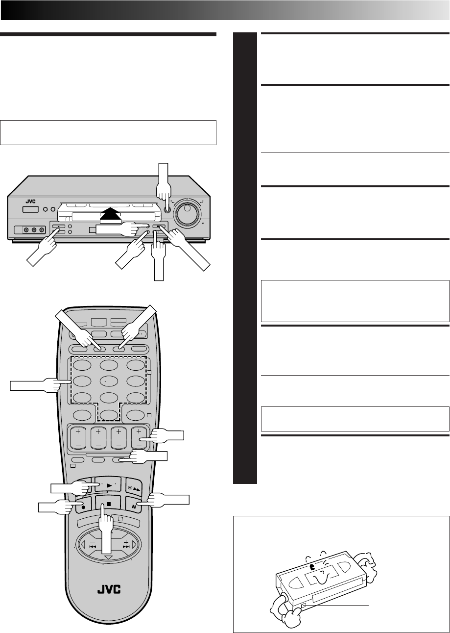
LOAD A CASSETTE
1
Make sure the record safety tab is intact. If not, cover the
hole with adhesive tape before inserting the cassette.
SELECT RECORDING
CHANNEL
2
Press CH5∞ (+/–). Or press the appropriate NUMBER
keys, then press ENTER. (The channel changes after a
few seconds whether you press ENTER or not.)
●If you use the RF connection, by pressing the TV/VCR
button, select VCR mode to view the program to be
recorded.
SET TAPE SPEED
3
Press SP/EP to set the recording speed.
START RECORDING
4
Press and hold REC and press PLAY on the remote
control, or press REC on the VCR's front panel.
Video Calibration takes place at the beginning of
both the first SP and the first EP recording after
inserting the cassette (when Video Calibration is set
to "ON", Z pg. 32).
PAUSE/RESUME
RECORDING
5
Press PAUSE. Press PLAY to resume recording.
●During record pause, you can change the recording
channel by using the CH5∞ (+/–) buttons or NUMBER
keys.
Video Calibration will not take place if the tape
speed is changed while in record pause mode.
STOP RECORDING
6
Press STOP or STOP/EJECT. Then press STOP/EJECT to
remove the cassette.
Turn on the TV and select the VCR channel 3 or 4 (or AV
mode).
●To prevent accidental recording on a recorded cassette,
remove its record safety tab.
To record on it later, cover the hole with adhesive tape.
Accidental erasure prevention
123
456
789
0
2
4
1
3
PLAY
PAUSE
REC
CH
PAUSE
STOP
REC
PLAY
SP/EP
CH
TV/VCR
ENTER
NUMBER
Record safety tab
SP/EP
STOP/EJECT
24 EN
PLAYBACK AND RECORDING FEATURES
Reverse
search
Reverse
Forward
search
Forward
Reverse
play Reverse
slow motion Slow motion Play
3 steps 5 steps 5 steps 4 steps
T
V
C
H
+
T
V
V
O
L
–
T
V
C
H
–
T
V
V
O
L
+
SHUTTLE
PLUS
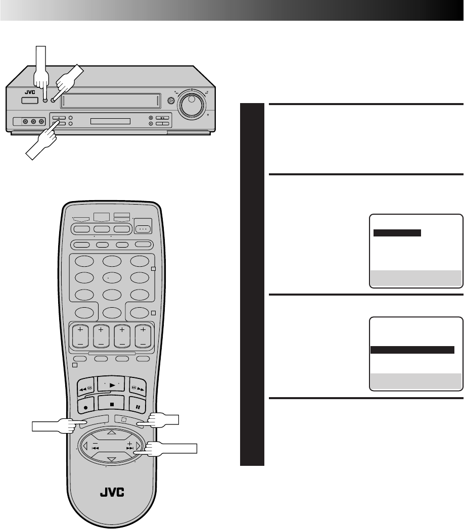
Playback
Features
Still Picture/Frame-By-
Frame Playback
PAUSE DURING PLAYBACK
1
Press PAUSE. If there is vertical jitter, use the CH 5 (+)
or ∞ (–) button to correct the picture.
ACTIVATE FRAME-BY-
FRAME PLAYBACK
2
Turn the JOG dial to the right for forward frame-by-
frame playback, or to the left for reverse frame-by-frame
playback.
OR
Press PAUSE repeatedly to advance one frame at a time.
OR
Press SHUTTLE PLUS £ repeatedly for forward frame-
by-frame playback or SHUTTLE PLUS ™ repeatedly
for reverse frame-by-frame playback.
To resume normal playback, press PLAY.
Slow Motion/Reverse Slow
Motion
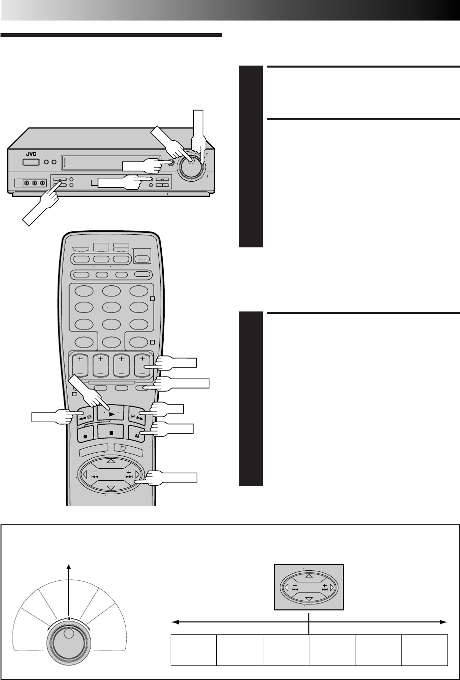
ACTIVATE SLOW-MOTION
PLAYBACK
1
For hands-free slow-motion, press and release
SHUTTLE PLUS ™ during playback to decrease
speed in the forward direction. Continue to press and
release SHUTTLE PLUS ™ to select the reverse slow
motion, reverse play and reverse search modes.
OR
During playback or still picture, turn the SHUTTLE ring
to the right for forward slow motion, or to the left for
reverse slow motion.
OR
During still picture, press and hold SHUTTLE PLUS £
for forward slow motion, or press and hold SHUTTLE
PLUS ™ for reverse slow motion. Release to return to
still picture.
To resume normal playback, press PLAY.
R
e
v
e
r
s
e
R
e
v
e
r
s
e
R
e
v
e
r
s
e
S
l
o
w
P
l
a
y
F
o
r
w
a
r
d
s
e
a
r
c
h
p
l
a
y
s
l
o
w
m
o
t
i
o
n
s
e
a
r
c
h
Still
m
o
t
i
o
n
PLAY
SHUTTLE
JOG
PAUSE
123
456
789
0
2
4
1
3
PAUSE
PLAY
NOTE: Refer to the following for the operations described above.
Shuttle Ring Modes
Forward search : 3 steps
Normal playback
Slow motion : 2 steps
Reverse slow motion : 2 steps
Reverse playback
Reverse search : 3 steps
CH+/–
CH5∞
SHUTTLE PLUS
FF
REW
SKIP SEARCH

EN 25
Manual Tracking
Once playback begins, the VCR’s automatic tracking function is
engaged. If tracking noise appears in the picture, you can
override this and make the adjustment manually.
ENGAGE MANUAL
TRACKING MODE
1
During playback, press the CH5 and ∞ buttons on the
VCR's front panel simultaneously to cancel the
automatic tracking mode and enable manual tracking
adjust.
ADJUST MANUAL
TRACKING
2
Press CH 5 (+) or ∞ (–) on the VCR's front panel or
remote. Press briefly for fine adjust, or press and hold for
coarse adjust. Watch the screen and continue adjusting
until optimum picture and sound quality are achieved.
RE-ENGAGE AUTOMATIC
TRACKING
3
Press the CH5 and ∞ buttons on the VCR's front panel
simultaneously.
●When automatic tracking is re-engaged, Video
Calibration is automatically activated.
NOTES:
●
To obtain a noiseless still picture it may be necessary to adjust
tracking in slow playback and then engage Pause.
●
Manual tracking is possible during hands-free slow-motion.
During hands-free slow-motion playback, simply press CH
5
(+) or
∞
(–) on the VCR's front panel or remote to adjust
tracking.
Index Search
Index codes are placed on the tape at the start of each
recording. You can find and automatically play back from the
start of any recording using the Index Search function.
START SEARCH
1
While the tape is stopped, press SHUTTLE PLUS ™
or £ ( or ).
ACCESS DISTANT CODE
2
To access a recording 2–9 index codes away, press
SHUTTLE PLUS ™ or £ ( or ) repeatedly until
the correct number is displayed on screen (only if
"SUPERIMPOSE" is set to "ON" (Z pg. 28). Playback
begins automatically when the desired recording is
located.
●If necessary press REW or FF when play starts to
search visually to find the very beginning of the
desired program.
NOTE:
An index code is not placed on the tape when recording is
paused and then resumed.
fi
%
fi
%
Skip Search
SKIP OVER UNWANTED
SECTIONS
1
Press SKIP SEARCH 1 to 4 times during playback. Each
press initiates a 30-second period of fast-motion
playback. Normal playback resumes automatically.
NOTES:
●
To return to normal playback during a Skip Search,
press PLAY.
●
When SKIP SEARCH is pressed during playback of a
prerecorded tape or a tape with the safety tab
removed, the Skip Menu is displayed (
Z
pag. 30).
When this menu is displayed, select "SKIP SEARCH"
to select the skip search function.
ACTIVATE VARIABLE-SPEED
SEARCH
1
During playback or still, turn the SHUTTLE ring to the
right for forward variable-speed search, or to the left for
reverse variable-speed search.
OR
During playback, repeatedly press and release SHUTTLE
PLUS ™ or £ to select the search speed.
●To increase the speed in the forward direction, press
and release £ repeatedly to select the various
forward search modes.
●To decrease the speed in the forward direction, press
and release ™.
●To play in reverse slow motion, and in reverse play
mode, continue to press ™ repeatedly after
selecting all the forward slow motion modes.
To resume normal playback, press PLAY.
Variable-Speed Search/
Reverse Motion Playback High-Speed Search
ACTIVATE HIGH-SPEED
SEARCH
1
During playback or still, turn the SHUTTLE ring all the
way to the right for forward high-speed search, or to
the left for reverse high-speed search. By releasing
SHUTTLE still picture playback is selected.
●For forward high-speed search, turn the SHUTTLE
ring all the way to the right and release it within 1
second.
●For reverse high-speed search, turn the SHUTTLE ring
all the way to the left and release it within 1 second.
OR
During playback or still, press FF for forward high-
speed search, or REW for reverse high-speed search.
To resume normal playback, press PLAY.
NOTE:
For short searches, during playback or still, press and hold FF or
REW for over 2 seconds. When released, normal playback
resumes.
26 EN
PLAYBACK AND RECORDING FEATURES (cont.)
Video Stabilizer
By activating the Video Stabilizer you can correct vertical
vibrations in the picture when playing back unstable EP
recordings that were made on another VCR. When this function
is set to "ON", vertical vibration will be automatically corrected.
*The default setting is "OFF".
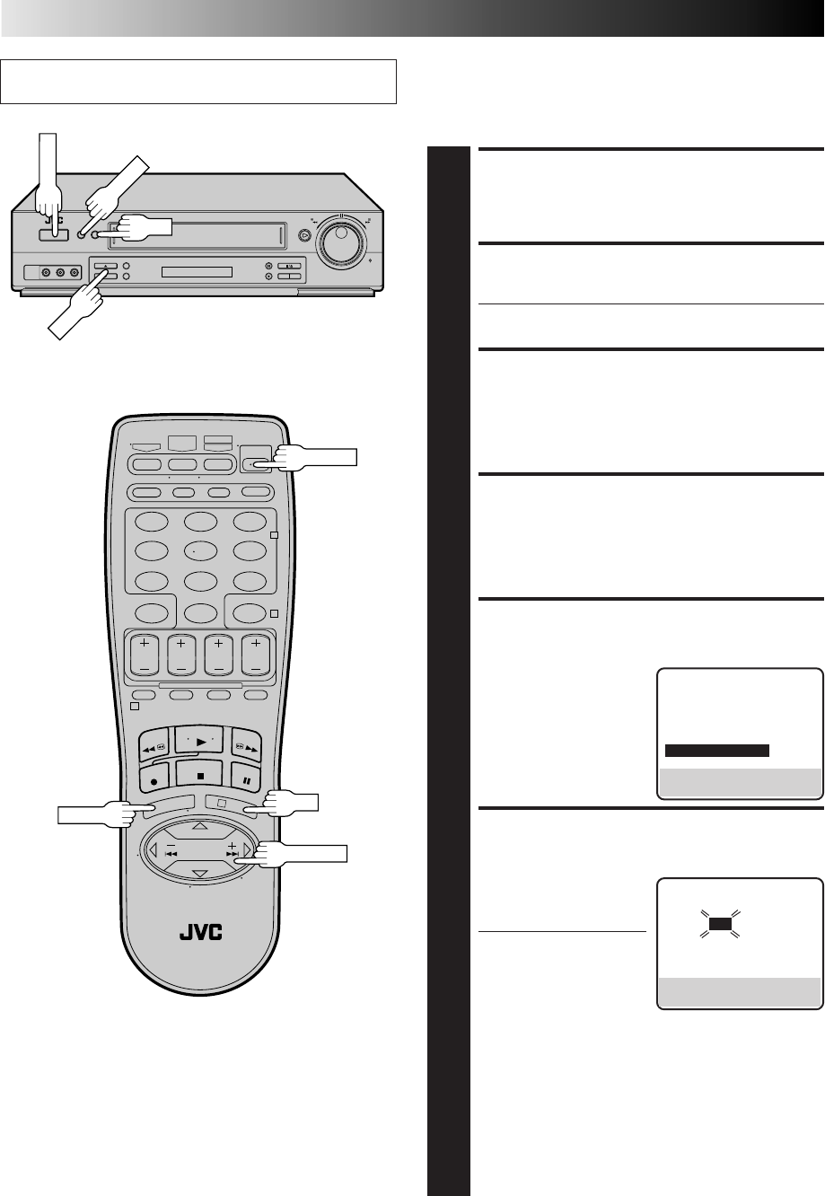
ACCESS MAIN MENU
SCREEN
1
Press MENU.
ACCESS FUNCTION SET
SCREEN
2
Move the highlight bar
(arrow) to "FUNCTION
SET" by pressing CH5∞ or
SHUTTLE PLUS %fi, then
press OK or SHUTTLE
PLUS .
ACTIVATE VIDEO STABILIZER
3
Move the highlight bar
(arrow) to "VIDEO
STABILIZER" by pressing
CH 5∞ or SHUTTLE PLUS
%fi, then press OK or
SHUTTLE PLUS to set to
"ON".
RETURN TO NORMAL
SCREEN
4
Press MENU.
%
%
MAIN MENU
=FUNCTION SET
TUNER SET
INITIAL SET
PRESS (5,∞), THEN (OK)
PRESS (MENU) TO END
NOTES:
●
Regardless of the setting, this function has no effect with SP
recordings, during recording and during special-effects
playback.
●
When you finish viewing the tape, be sure to set it back to
"OFF".
FUNCTION
AUTO TIMER OFF
SUPERIMPOSE ON
AUTO SP=EP TIMER OFF
=VIDEO STABILIZER ON
2ND AUDIO RECORD OFF
AUDIO MONITOR HI-FI
NEXT PAGE
SELECT WITH (5,∞) AND (OK)
PRESS (MENU) TO END
MENU
123
456
789
0
2
4
1
3
OK
OK
MENU
SHUTTLE PLUS
CH
EN 27
Repeat Playback
123
456
789
0
2
4
1
3
C.RESET
POWER
DISPLAY
POWER
TIMER
FF
PAUSE
REW
STOP
PLAY
STOP
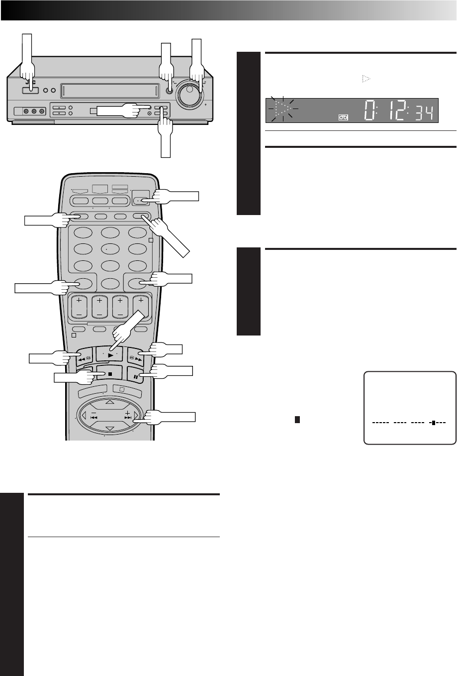
START REPEAT
1
Press and hold PLAY (until " " blinks on the front
display panel) during playback, then release.
●The entire tape is played back 50 times.
STOP REPEAT
2
To stop, press STOP at any time.
NOTE:
Pressing PLAY, REW, FF, PAUSE or SHUTTLE PLUS
™
or
£
also stops Repeat Playback.
Tape Position Indicator
The Tape position indicator
appears on screen when, from the
stop mode, you press FF, REW, or
use the SHUTTLE ring, or perform
an Index Search or Instant ReView.
The position of " " in relation to
"B" (Beginning) or "E" (End) shows
you where you are on the tape.
NOTES:
●
"SUPERIMPOSE" must be set to "ON", or the indicator will not
appear (
Z
pg. 28).
●
It may take a few seconds for the Tape Position Indicator to be
displayed.
COUNT 0:33:27
BE
+++
Next-Function Memory
The Next Function Memory “tells” the VCR what to do after
rewinding. Before continuing, ensure that the VCR is in stop
mode.
a– For Automatic Start Of Playback After Tape Rewind . . .
. . . press REW, then press PLAY within 2 seconds.
b– For Automatic Power Off After Tape Rewind . . .
. . . press REW, then press POWER within 2 seconds.
c– For Automatic Timer Standby After Tape Rewind . . .
. . . press REW, then press TIMER within 2 seconds.
NOTE:
It is not possible to select the Automatic Timer functions if the
cassette's record safety tab is removed.
SP VCR
RESET COUNTER TO ZERO
1
Press C.RESET.
NOTE:
By pressing the DISPLAY button, you can change the
display to show the counter reading, channel number
or clock time. (Channel number is not displayed during
playback.)
Counter Reset
PLAY
PAUSE
SHUTTLE PLUS
SHUTTLE
Instant ReView
At the press of a button, you can power up your VCR, rewind the
tape and begin viewing the most recently recorded or timer-
recorded program.
ACTIVATE INSTANT REVIEW
1
After ensuring that the Timer mode is disengaged, press
REVIEW.
●The power comes on and the VCR rewinds to the index
code indicating the start of the last timer-recorded
program, then begins playback automatically.
●You can access a program 2–9 index codes away
from the current position on the tape. If, for example,
you have 5 programs recorded and you want to
watch the third one, press REVIEW three times.
●If necessary press REW or FF when play starts to
search visually to find the very beginning of the
desired program.
●If the tape is already rewound when REVIEW is
pressed, it will play the tape from the beginning. It
will not fast forward to an index code.
●The Instant Review function will also operate if the
VCR's power is on.
REVIEW
28 EN
Superimpose
CH 125 RECORD
THU 12:00 AM PAUSE
STEREO ] SP
SAP
INDEX-1
NORM
HI–FI COUNT –1:23:45
BE
+++
PLAYBACK AND RECORDING FEATURES (cont.)
Tuned-in channel or AUX(iliary) mode
When the channel is changed, the new
channel is displayed on the screen for 5
seconds.
Operation mode
When the operation mode is changed,
the new mode is displayed — RECORD
(5 sec.), PLAY (5 sec.), FF/REW (5 sec.
when engaged from Stop mode),
RECORD PAUSE (for as long as Pause is
engaged), and ITR *:** (5 sec.).
INDEX indication
Tape speed indication
"Cassette Loaded" mark
When a cassette is loaded, the mark is
displayed for 5 seconds. It blinks when the
VCR's EJECT button is pushed.
Audio mode
indications
Tape position indicator
Second Audio Program indication
Stereo program indication
Clock time
The superimposed indication on the TV screen tells you what the VCR is doing.
Counter reading
Switchable to the tape
remaining time display
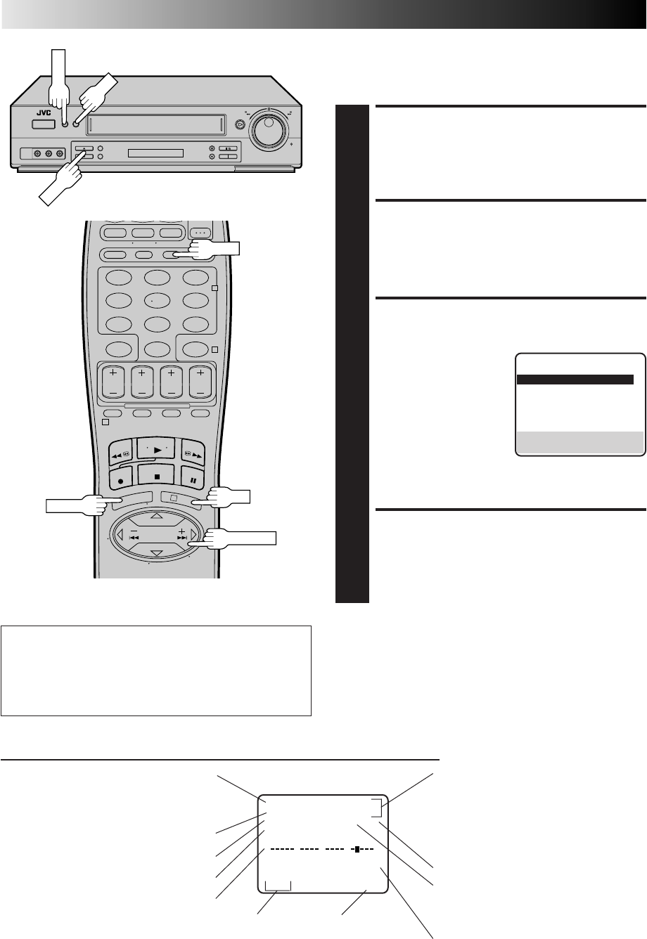
This function, switchable between ON and OFF, determines
whether or not operational indicators will appear on screen.
ACCESS MAIN MENU
SCREEN
1
Press MENU.
ACCESS FUNCTION SET
SCREEN
2
Move the highlight bar (arrow) to "FUNCTION SET" by
pressing CH5∞ or SHUTTLE PLUS %fi, then press OK
or SHUTTLE PLUS .
SELECT SUPERIMPOSE SET
MODE
3
Move the highlight bar
(arrow) to "SUPERIMPOSE"
by pressing CH5∞ or
SHUTTLE PLUS %fi, then
press OK or SHUTTLE
PLUS to select the
desired mode:
a– Select "ON" if you want
the superimposed
operational indications on the TV screen.
b– Select "OFF" if you do not want the superimposed
operational indications on the screen.
RETURN TO NORMAL
SCREEN
4
Press MENU.
%
%
NOTES:
●
If you engage the Record Pause mode, RECORD/PAUSE is
displayed regardless of the Superimpose mode setting.
●
If you select a channel on which no signal is received, the
channel number is displayed regardless of the Superimpose
mode setting.
To recall an indication
1Press OSD.
nAll indications corresponding to the current status are
displayed for 5 seconds. After that, the counter
information and RECORD/PAUSE if in the Record Pause
mode, are left displayed on the screen.
2Press OSD again to clear the display.
MENU
123
456
789
0
2
4
1
3
CH
OK
OK
MENU
OSD
FUNCTION
AUTO TIMER OFF
=SUPERIMPOSE ON
AUTO SP=EP TIMER OFF
VIDEO STABILIZER OFF
2ND AUDIO RECORD OFF
AUDIO MONITOR HI-FI
NEXT PAGE
SELECT WITH (5,∞) AND (OK)
PRESS (MENU) TO END
SHUTTLE PLUS
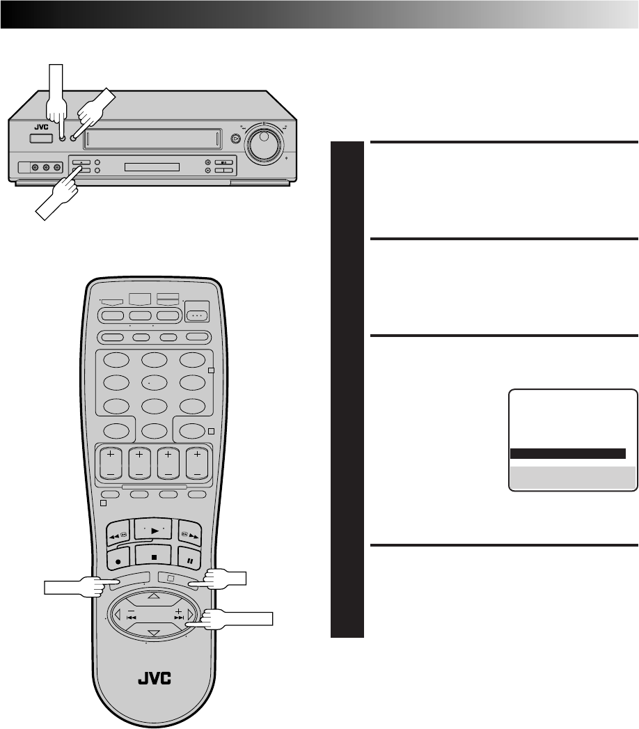
EN 29
Select The Soundtrack
Your VCR can record two soundtracks simultaneously (Normal
and Hi-Fi) and play back the selected one, or both together. Or,
when viewing a pre-recorded tape that contains two separate
Hi-Fi audio programs, you can choose to listen to either one by
selecting either "Hi-Fi L" or "Hi-Fi R" in step 3.
ACCESS MAIN MENU
SCREEN
1
Press MENU.
ACCESS FUNCTION SET
SCREEN
2
Move the highlight bar (arrow) to "FUNCTION SET" by
pressing CH5∞ or SHUTTLE PLUS %fi, then press OK
or SHUTTLE PLUS .
SELECT AUDIO MONITOR
SET MODE
3
Move the highlight bar
(arrow) to "AUDIO
MONITOR" by pressing
CH 5∞ or SHUTTLE PLUS
%fi, then press OK or
SHUTTLE PLUS to
select the desired mode:
a– Hi-Fi
b– Hi-Fi L
c– Hi-Fi R
d– Normal
e– Mix
RETURN TO NORMAL
SCREEN
4
Press MENU.
%
%
NOTES:
●
If the tape being played back has no Hi-Fi soundtrack, the
Normal soundtrack will be heard no matter what choice you
make in step 3.
●
If RF connection is used for TV, even if Hi-Fi audio monitor is
selected the sound will be mono and will be reproduced in
both loudspeakers.
MENU
123
456
789
0
2
4
1
3
CH
OK
OK
MENU
FUNCTION
AUTO TIMER OFF
SUPERIMPOSE ON
AUTO SP=EP TIMER OFF
VIDEO STABILIZER OFF
2ND AUDIO RECORD OFF
=AUDIO MONITOR HI-FI
NEXT PAGE
SELECT WITH (5,∞) AND (OK)
PRESS (MENU) TO END
SHUTTLE PLUS
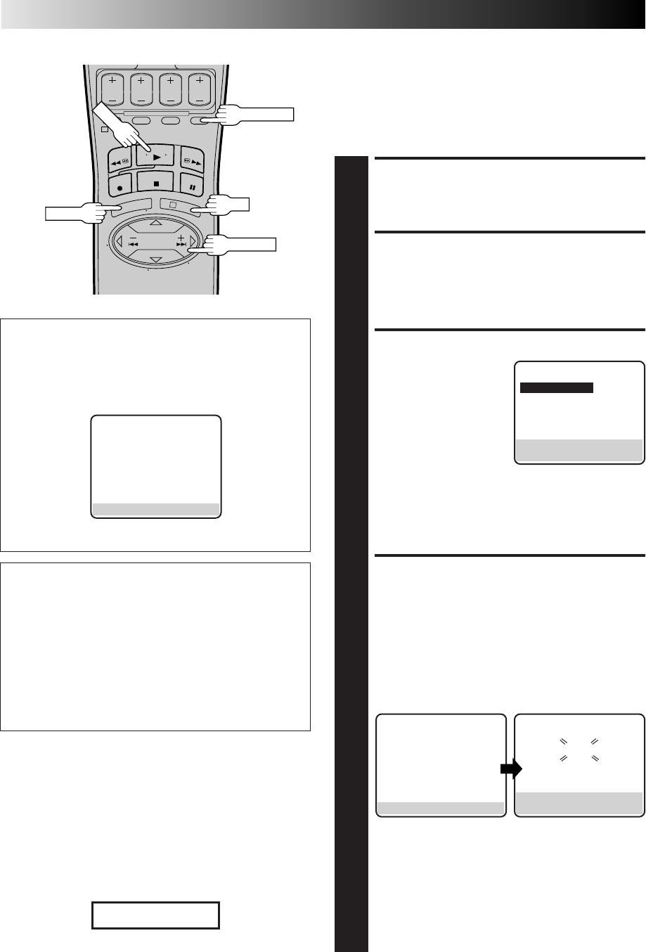
30 EN
1
3
PLAYBACK AND RECORDING FEATURES (cont.)
Movie Advance
This feature helps you locate certain parts of prerecorded movies
(rented or purchased) and works in two ways.
● You can go to the beginning of the movie, skipping over all
previews.
●You can fast-motion the tape to the beginning of the next
preview, so you can skip over previews one by one.
LOAD A CASSETTE
1
Insert a cassette that has a prerecorded movie (rented or
purchased), with no safety tab, into the VCR. Playback
begins automatically.
ACCESS SKIP MENU
SCREEN
2
Press SKIP SEARCH.
SELECT MODE
3
Press CH5∞ or SHUTTLE
PLUS %fi to move the
highlight bar (arrow) to
your choice.
a– Select "MOVIE
ADVANCE" if you want
to advance directly to
the beginning of the
movie.
b– Select "MOVIE ADVANCE (PREVIEW)" if you want
to advance to the next preview.
c– Select "SKIP SEARCH" if you do not want to perform
Movie Advance, then press OK to go back to the
normal screen. Pressing SKIP SEARCH activates the
Skip Search function (Z pg. 25 ).
PERFORM MOVIE
ADVANCE
4
a– If you selected "MOVIE ADVANCE" in step 3 and
press OK, the following screen will appear with a
blue background. The VCR will rewind the
beginning of the tape, then will fast-motion to the
beginning of the movie. "READY" will appear and
blink when the beginning of the movie is detected
and the Stop mode will be engaged. Press PLAY to
view the movie.
b– If you selected "MOVIE ADVANCE (PREVIEW)" in
step 3 and press OK, the VCR will fast-motion to the
beginning of the next preview and normal playback
will resume when it is detected.
Each press of SKIP SEARCH fast-motions to the
beginning of the next preview, thereby skipping over
one preview each time.
The tape will forward-search a little past the start of
the next preview, then will reverse-serach to the
beginning of the preview and start playback.
SKIP MENU
=MOVIE ADVANCE
MOVIE ADVANCE (PREVIEW)
SKIP SEARCH
PRESS (5,∞), THEN (OK)
PRESS (SKIP) TO CANCEL
ATTENTION
Movie Advance and Movie Advance (Preview) works only
on prerecorded cassettes that have been recorded in the SP
mode, and have no safety tab. If the VCR detects the EP
mode after you press OK in step 4, the following screen
appears.
MOVIE ADVANCE
MOVIE ADVANCE CAN NOT
BE SELECTED FOR EP
RECORDINGS.
PRESS (SKIP) TO CANCEL
NOTES:
●
Normally there is a period of black and no audio at the
beginning and end of previews. The Movie Advance feature
detects those parts where the picture fades to black and the
audio fades to silence, and initiates fast-motion to skip over
the detected previews.
●
Some previews may not be detected and Movie Advance may
not work properly.
●
The setting you selected in step 3 remains in effect until the
cassette is ejected.
Patents Pending
SKIP SEARCH
PLAY
OK
MENU
SHUTTLE PLUS
When "MOVIE ADVANCE" is selected...
●If you want to stop searching for the start of the movie,
simply press SKIP SEARCH or STOP.
When "MOVIE ADVANCE (PREVIEW)" is selected...
●If SKIP SEARCH was inadvertently pressed, press it again
to resume normal playback.
●While the VCR is searching for the next preview, if you
see a preview you wish to view, press SKIP SEARCH and
the VCR will immediately go to the start of that preview.
●If the VCR starts to reverse to a preview you do not wish
to view, press SKIP SEARCH to initiate searching to the
next preview.
Skip Search will work for prerecorded
EP tapes.
MOVIE ADVANCE
READY
PRESS (PLAY) TO START
PRESS (STOP) TO CANCEL
MOVIE ADVANCE
SEARCHING FOR BEGINNING
OF MOVIE.
PRESS (STOP) TO CANCEL
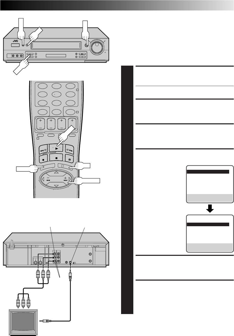
EN 31
AV COMPU LINK Playback
Your VCR is compatible with JVC’s AV COMPU LINK components,
including amplifiers (or receivers) and televisions. AV COMPU
LINK provides one touch control of the audio and video compo-
nents that are linked via their AV COMPU LINK connectors.
For example: simply load a cassette in the VCR and press PLAY and
the AV COMPU LINK components automatically power on, the TV's
AV mode is selected and the VCR goes into play mode. (PLAY need
not be pressed if the cassette's record safety tab is removed.)
MAKE CONNECTION
1
Connect your VCR to an AV COMPU LINK component
as shown in the illustration in the left column.
●The mini-plug cable is a mono 3.5 mm mini-plug to
mono 3.5 mm mini-plug connector.
ACCESS MAIN MENU SCREEN
2
Press MENU.
ACCESS FUNCTION SET SCREEN
3
Press CH5∞ or SHUTTLE PLUS %fi to move the
highlight bar (arrow) to “FUNCTION SET”, then press
OK or SHUTTLE PLUS .
ENABLE AV COMPU LINK
PLAYBACK
4
Press CH5∞ or SHUTTLE
PLUS %fi to move the
highlight bar (arrow) to
“AV COMPU-LINK”, then
press OK or SHUTTLE
PLUS to set to "ON".
RETURN TO NORMAL SCREEN
5
Press MENU.
PERFORM AV COMPU LINK
PLAYBACK
6
Simply insert a cassette and press PLAY (if the cassette’s
record safety tab has been removed, playback begins
automatically). Linked components are turned on, and
the TV set to its AV mode, automatically!
NOTE:
Connection varies depending on the type of JVC TV you have.
Please refer to the TV’s instruction manual when making this
connection.
AV COMPU LINK II
(VCR ONLY)
VIDEO
IN AUDIO
IN
AV COMPU LINK
Television
Your VCR
VIDEO OUT
AUDIO
OUT
Mini-plug cable
(not supplied)
Audio/Video cable
(supplied)
Example REMOTE PAUSE/
AV COMPULINK
%
%
MENU
123
456
789
0
2
4
1
3
CH
OK
OK
MENU
PLAY
PLAY
FUNCTION
=AUTO TIMER OFF
SUPERIMPOSE ON
AUTO SP=EP TIMER OFF
VIDEO STABILIZER OFF
2ND AUDIO RECORD OFF
AUDIO MONITOR HI-FI
NEXT PAGE
SELECT WITH (5,∞) AND (OK)
PRESS (MENU) TO END
PREVIOUS PAGE
S-VHS MODE AUTO
=AV COMPU-LINK ON
VIDEO CALIBRATION ON
REAR AUX INPUT VIDEO
TAPE DUB MODE ON
SELECT WITH (5,∞) AND (OK)
PRESS (MENU) TO END
SHUTTLE PLUS
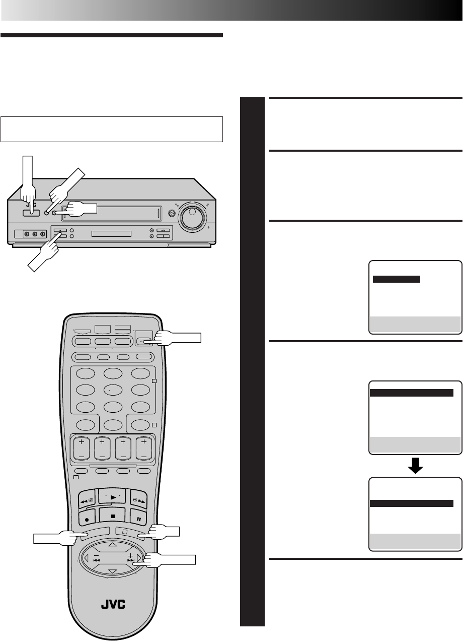
32 EN
PLAYBACK AND RECORDING FEATURES (cont.)
Active Video
Calibration
Active Video Calibration checks the condition of the tape
during recording and playback, and compensates for poor
reproduction to provide the best quality recording and playback
pictures. *The default setting is "ON".
Turn on the TV and select the VCR channel 3 or 4 (or AV
mode).
Preparation
TURN ON THE VCR
1
Press POWER.
ACCESS MAIN MENU
SCREEN
2
Press MENU.
ACCESS FUNCTION SET
SCREEN
3
Press CH5∞ or SHUTTLE
PLUS %fi to move the
highlight bar (arrow) to
“FUNCTION SET”, then
press OK or SHUTTLE
PLUS .
SELECT VIDEO
CALIBRATION MODE
4
Press CH 5∞ or SHUTTLE
PLUS %fi to move the
highlight bar (arrow) to
"VIDEO CALIBRATION",
then press OK or SHUTTLE
PLUS to set to "ON" or
"OFF".
NOTE:
When recording or when
playing back tapes
recorded on this VCR set
the Video Calibration to
"ON".
RETURN TO NORMAL
SCREEN
5
Press MENU.
%
MAIN MENU
=FUNCTION SET
TUNER SET
INITIAL SET
PRESS (5,∞), THEN (OK)
PRESS (MENU) TO END
%
FUNCTION
=AUTO TIMER OFF
SUPERIMPOSE ON
AUTO SP=EP TIMER OFF
VIDEO STABILIZER OFF
2ND AUDIO RECORD OFF
AUDIO MONITOR HI-FI
NEXT PAGE
SELECT WITH (5,∞) AND (OK)
PRESS (MENU) TO END
POWER
123
456
789
0
2
4
1
3
POWER
CH
OK
MENU
MENU
OK
SHUTTLE PLUS
PREVIOUS PAGE
S-VHS MODE AUTO
AV COMPU-LINK ON
=VIDEO CALIBRATION ON
REAR AUX INPUT VIDEO
TAPE DUB MODE ON
SELECT WITH (5,∞) AND (OK)
PRESS (MENU) TO END
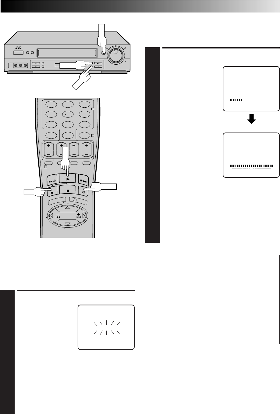
EN 33
Recording
Perform steps 1 – 3 on page 23 ("Simple Recording") before
continuing.
ATTENTION
nAs calibration takes place before recording actually starts,
there is a delay of about 7 seconds after REC and PLAY on
the remote, or REC on the VCR's front panel, are pressed.
To make sure you record the desired scene or program
completely, first perform the following steps:
1) Press and hold PAUSE, and press REC to engage the
RECORD PAUSE mode.
●The VCR then automatically checks the condition of
the tape and, after about 7 seconds, re-enters
RECORD PAUSE.
2) Press PLAY to start recording.
nIf you want to bypass Video Calibration and start
recording right away, set "VIDEO CALIBRATION" to
"OFF" in step 4 of the Preparation procedure (Z pg. 32).
START PLAYBACK
1
Press PLAY.
●The VCR adjusts the
playback picture quality
based on the quality of
the tape in use.
NOTES:
●
When using rental tapes,
or tapes recorded on other VCRs, set “VIDEO
CALIBRATION” in step 4 of the Preparation proce-
dure to either “ON” or “OFF” as desired to give the
best picture (
Z
pg. 32).
●
The Video Calibration screen only appears at the
beginning of automatic tracking. Even though the
screen doesn't appear after that, the Video calibration
function is operative.
●
To display the Video Calibration screen, “SUPERIM-
POSE” must be set to "ON" or the Video Calibration
screen will not appear (
Z
pg. 28).
START RECORDING
1
Press and hold REC and
press PLAY on the remote
control, or press REC on
the VCR's front panel.
●The VCR takes about 7
seconds to assess the
quality of the tape in
use, then recording
begins with the picture
level optimized.
NOTES:
●
Calibration occurs
immediately prior to
both the first SP and the
first EP recording after
inserting the cassette. It
does not take place
during recording.
●
In the case of timer
recording, calibration
takes place for both SP and EP before the first timer
recording after inserting the cassette (regardless of the
tape speed selected for that recording).
●
Once the cassette is ejected, the calibration data is
canceled. The next time the cassette is used for
recording, calibration is re-performed.
●
While Video Calibration is operative, the PAUSE
button will not function.
●
To display the Video Calibration screen, "SUPERIM-
POSE" must be set to "ON" or the Video Calibration
screen will not appear (
Z
pg. 28).
Playback
The VCR assesses the quality of the tape once you start
playback.
Perform steps 1 and 2 on page 22 ("Simple Playback") before
continuing.
VIDEO CALIBRATION
START END
ACTIVE VIDEO CALIBRATION
++
++
DURING CALIBRATION
CALIBRATION COMPLETE
START END
ACTIVE VIDEO CALIBRATION
++
++
PLAY
REC
123
456
789
0
2
4
1
3
PLAY
PAUSE
REC
PAUSE
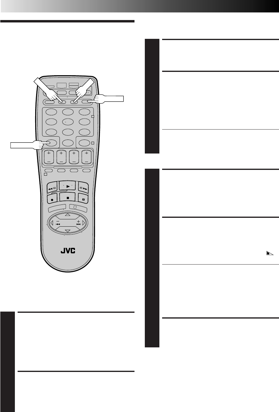
34 EN
PLAYBACK AND RECORDING FEATURES (cont.)
Record One Program While
Watching Another
Recording
Features
ENGAGE TV MODE
1
During recording...
●Press TV/VCR. The VCR's VCR indicator goes out. (If
you are using the RF connection (Z pg. 6) to view
the output from your VCR, the TV broadcast being
recorded disappears.)
●If you are using the AV connection (Z pg. 6) to view
the output from your VCR, change the TV's input
mode from AV to TV.
SELECT CHANNEL FOR
VIEWING
2
Use the TV’s channel selector to set the channel you
want to watch.
RESET COUNTER TO ZERO
1
Before recording starts, press C.RESET. The counter
resets to zero and displays the exact elapsed time as the
tape runs.
DISPLAY ELAPSED TIME ON
SCREEN
2
During recording, press OSD at any time to see the
elapsed time.
All indications corresponding to the current status of the
VCR are displayed for 5 seconds. The counter display
remains on the screen indicating the elapsed time.
Press OSD again to remove the display.
●Make sure "SUPERIMPOSE" is set to "ON" (Z pg. 28).
●The indications are not recorded.
●Press DISPLAY to change to the COUNT display if
"REMAIN" is displayed.
Display Elapsed Recording
Time
123
456
789
0
2
4
1
3
OSD
TV/VCR
C.RESET
Display Tape Remaining Time
DISPLAY COUNTER
INFORMATION
1
Press OSD.
All indications corresponding to the VCR's current
status are displayed for 5 seconds. The counter display
remains on the screen indicating the elapsed time.
DISPLAY TAPE REMAINING
TIME
2
Press DISPLAY until "REMAIN" appears on screen. The
approximate tape remaining time appears on the TV
screen and also on the VCR display panel with a " "
indicator.
●The tape remaining time is calculated based on the
tape speed (SP or EP) being used. The indicated
remaining time is only an estimate.
●Press DISPLAY to change the on-screen display from
REMAIN to COUNT and vice versa; and to show
counter reading, channel number, clock time or tape
remaining time on the front display panel. Then
channel number will not be displayed when the VCR
is playing a tape.
EXIT THE DISPLAY
3
Press OSD again.
NOTES:
●
"SUPERIMPOSE" must be set to "ON", or the on-screen
display will not appear (
Z
pg. 28).
●
Near the beginning of the tape, the tape remaining estimate
may be inaccurate. However, the estimate becomes more
accurate as the tape comes closer to the end.
●
Depending on the type of tape used, the tape remaining time
reading may not appear right away, or may not be correct. "- -:- -"
may sometimes appear, or the display may blink on occasion.
●
The tape remaining time indication is not accurate when
using VHS-C tapes with VHS-C adapter.
DISPLAY
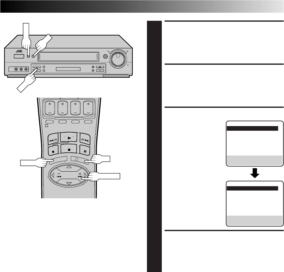
EN 35
ACCESS MAIN MENU
SCREEN
1
Press MENU.
ACCESS FUNCTION SET
SCREEN
2
Move the highlight bar (arrow) to "FUNCTION SET" by
pressing CH5∞ or SHUTTLE PLUS%fi, then press OK
or SHUTTLE PLUS .
SELECT S-VHS MODE
3
Move the highlight bar
(arrow) to "S-VHS MODE"
by pressing CH5∞ or
SHUTTLE PLUS%fi, then
press OK or SHUTTLE
PLUS to set to "ON" or
"OFF".
RETURN TO NORMAL
SCREEN
4
Press MENU.
NOTE:
When playing back a tape that has been recorded in S-VHS or
S-VHS ET, the S-VHS indicator lights on the display panel
regardless of the "S-VHS MODE" setting.
S-VHS (Super VHS), S-VHS
ET and VHS
Your VCR can record in S-VHS, S-VHS ET or VHS.
S-VHS allows you to make high quality video recordings with a
horizontal resolution of 400 lines. This compares with the 240
lines of resolution of normal VHS recordings. To achieve the
highest quality picture we recommend that you record in S-VHS
mode.
By using S-VHS ET it is possible to record and play back with S-
VHS picture quality on VHS cassettes with this VCR. For details,
refer to page 36.
To record in S-VHS;
●perform the steps 1 – 4 below to set the "S-VHS MODE" to
"ON".
●then, insert a cassette marked "S-VHS", the S-VHS indicator
will light on the display panel.
The S-VHS recording mode will be automatically selected.
To record in S-VHS ET on a VHS cassette;
Z "Super VHS ET" on page 36.
To record in VHS;
●insert a cassette marked "VHS".
The VHS recording mode will be automatically selected
regardless of the S-VHS mode setting.
To record in VHS on an S-VHS cassette;
●insert the cassette marked "S-VHS", the S-VHS indicator will
light on the display panel.
●then, perform the steps 1 – 4 below to set the "S-VHS MODE"
to "OFF"; the S-VHS indicator will go out.
The VHS recording mode will be selected.
NOTE:
Tapes recorded in S-VHS or S-VHS ET mode can not be played
back successfully on normal VHS VCRs.
%
FUNCTION
=AUTO TIMER OFF
SUPERIMPOSE ON
AUTO SP=EP TIMER OFF
VIDEO STABILIZER OFF
2ND AUDIO RECORD OFF
AUDIO MONITOR HI-FI
NEXT PAGE
SELECT WITH (5,∞) AND (OK)
PRESS (MENU) TO END
%
1
3
CH
OK
MENU
MENU
OK
SHUTTLE PLUS
PREVIOUS PAGE
=S-VHS MODE ON
AV COMPU-LINK ON
VIDEO CALIBRATION ON
REAR AUX INPUT VIDEO
TAPE DUB MODE ON
SELECT WITH (5,∞) AND (OK)
PRESS (MENU) TO END
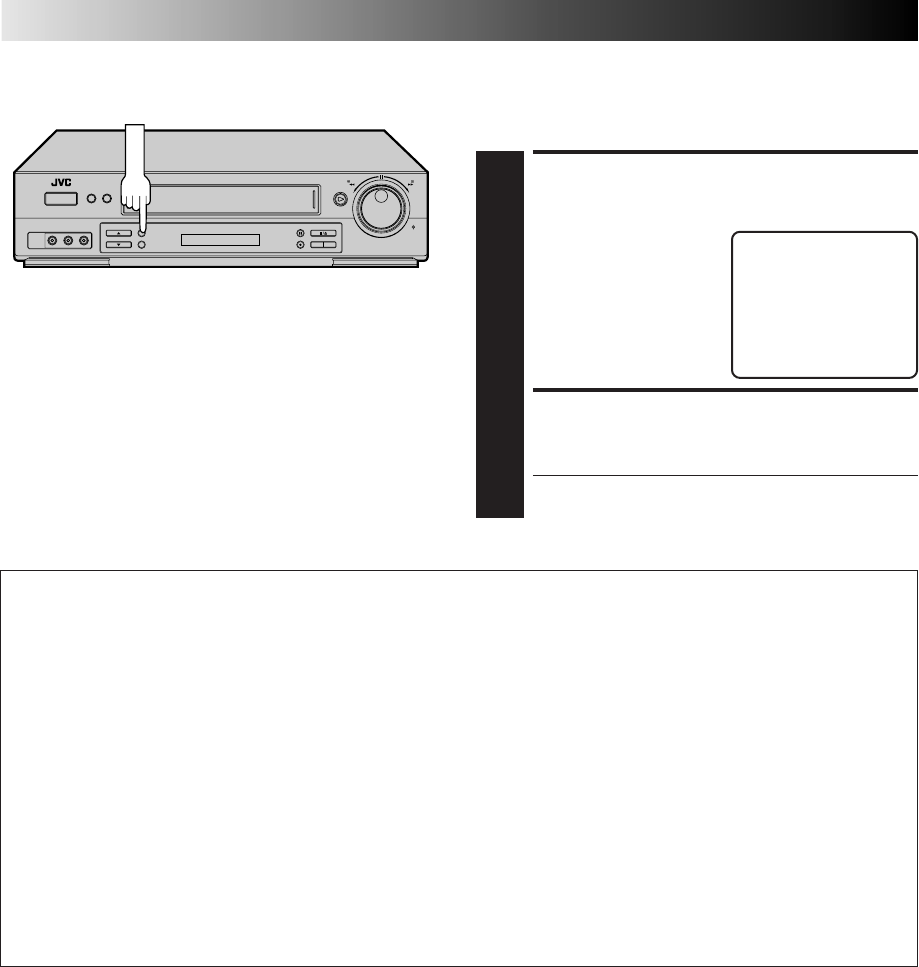
36 EN
PLAYBACK AND RECORDING FEATURES (cont.)
Super VHS ET
Your VCR is equipped with Super VHS ET that makes it possible
to record with S-VHS picture quality on VHS cassettes.
SELECT S-VHS ET SET
MODE
1
Press S-VHS ET. The
current setting appears on
the screen for about 5
seconds.
ENGAGE S-VHS ET MODE
2
While the current setting is displayed on the screen,
press S-VHS ET again to set to "ON".
● The "S-VHS" indicator lights on the front display
panel.
S-VHS ET : OFF
S-VHS ET
NOTES:
●
You cannot activate the S-VHS ET function...
...while recording is in progress.
...while timer-recording (incl. Instant Timer Recording
Z
pg.
46 and Automatic Satellite Program Recording
Z
pg. 47) is
in progress.
...while Video Calibration (
Z
pg. 32) is in progress.
...when the VCR's power is off.
●
S-VHS ET does not work with S-VHS tapes.
S-VHS ET
This facility allows recording with S-VHS picture quality on VHS cassettes. You can play back those cassettes recorded in S-VHS
ET on a VCR equipped with S-VHS ET.
NOTES:
●
To obtain the highest quality recording and playback pictures over a longer period on this model, S-VHS recording on S-VHS
tape is recommended.
●
You can play back S-VHS ET recordings not only on this VCR but also on another VHS VCR equipped with S-VHS ET.
* It is recommended to specifically label S-VHS ET recordings so you can easily distinguish them from regular VHS recordings.
●
S-VHS ET recordings can also be played back on an S-VHS VCR or a VHS VCR equipped with SQPB (S-VHS QUASI PLAY-
BACK) function. However, there may be cases where S-VHS ET playback is not possible on a particular VCR.
●
Frequent still, frame-by-frame and slow-motion playback may damage the tape and cause picture degradation.
●
With some tapes, better picture quality may not be obtained even with S-VHS ET recording. It is recommended that you do
test record beforehand to make sure whether better results can be obtained.
●
High Grade tapes are recommended for superior results.
●
Make sure that "VIDEO CALIBRATION" is set to "ON" at the Function screen (
Z
pg. 32).
●
During S-VHS ET playback, noise may appear depending on tape quality.
●
Noise may appear during still, frame-by-frame and slow-motion playback.
●
If the playback picture becomes blurred or interrupted, use a cleaning cassette.
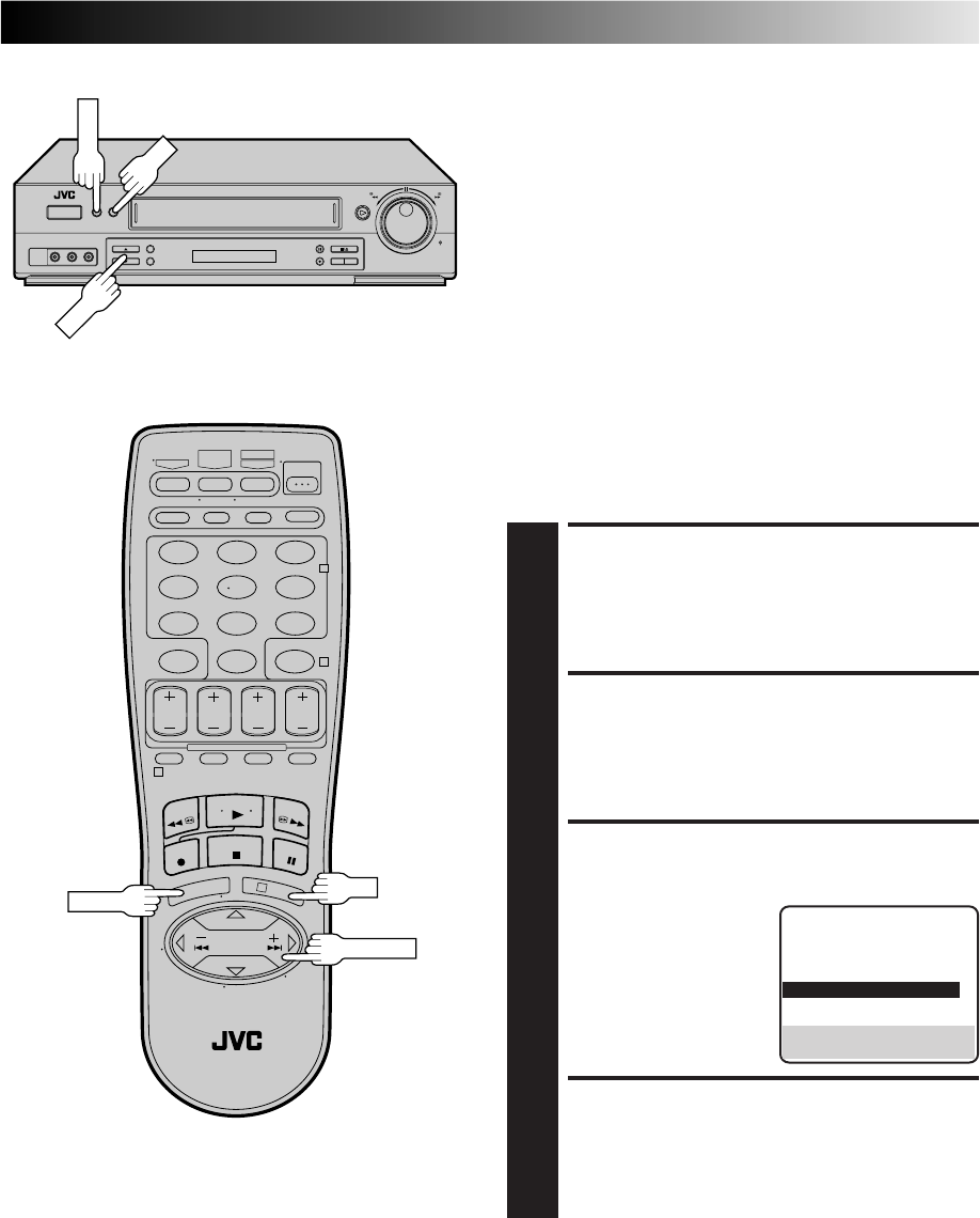
EN 37
Stereo And SAP
(Second Audio Program)
Your VCR’s built-in MTS decoder enables reception of Multi-
channel TV Sound broadcasts.
When the channel is changed on the VCR ...
●The "STEREO" indication appears on the screen for about 5
seconds if the program is a stereo broadcast.
●The "SAP" indication appears on the screen for about 5
seconds if the program is a SAP broadcast.
●Both indications appear when a stereo program is
accompanied by SAP audio.
To Record Stereo Programs . . .
. . . simply follow the basic recording procedure.
To Listen To Stereo Soundtrack During Recording . . .
. . . set "AUDIO MONITOR" to "HI-FI" at the Function screen
(Z pg. 29).
NOTES:
●
If a SAP program is received and "2ND AUDIO RECORD" is
set to "ON", the SAP audio is recorded on both the Normal
and Hi-Fi tracks. The main audio program is not recorded.
●
If a non-SAP program is received, the main audio is recorded
on both the Hi-Fi and Normal audio tracks.
To Record SAP Programs . . .
ACCESS MAIN MENU
SCREEN
1
Press MENU.
ACCESS FUNCTION SET
SCREEN
2
Move the highlight bar (arrow) to "FUNCTION SET" by
pressing CH5∞ or SHUTTLE PLUS %fi, then press OK
or SHUTTLE PLUS .
SELECT 2ND AUDIO
RECORD SET MODE
3
Move the highlight bar
(arrow) to "2ND AUDIO
RECORD" by pressing
CH5∞ or SHUTTLE
PLUS%fi, then press OK
or SHUTTLE PLUS to set
to "ON".
RETURN TO NORMAL
SCREEN
4
Press MENU.
%%
MENU
123
456
789
0
2
4
1
3
CH
OK
OK
MENU
FUNCTION
AUTO TIMER OFF
SUPERIMPOSE ON
AUTO SP=EP TIMER OFF
VIDEO STABILIZER OFF
=2ND AUDIO RECORD ON
AUDIO MONITOR HI-FI
NEXT PAGE
SELECT WITH (5,∞) AND (OK)
PRESS (MENU) TO END
SHUTTLE PLUS
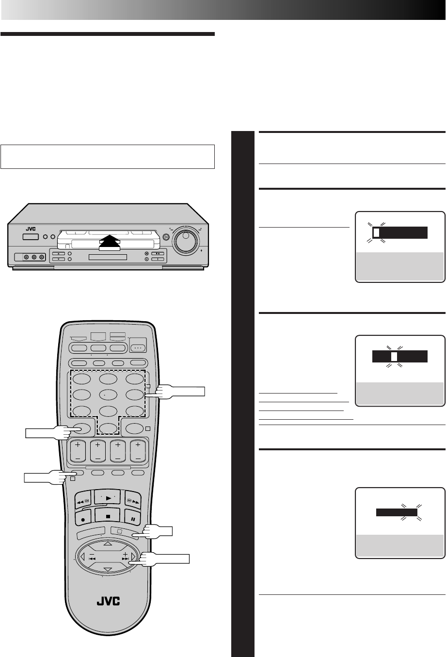
38 EN
VCR Plus+
Timer
Programming
Turn on the TV and select the VCR channel 3 or 4 (or AV
mode).
Timer recording allows you to program the VCR to automatically
record a program that will be broadcast at some future time.
The timer record function can be programmed using VCR Plus+
or Express Timer Programming up to 8 shows as far as a year in
advance. (Z pg. 38 or 42)
The VCR Plus+ timer programming system eliminates the need
to input channel, date, start and stop time data when setting the
timer record function. Simply key in the PlusCode number for
the TV program you wish to record and the VCR's timer will be
automatically programmed. (The PlusCodes are the numbers
next to the programs in most TV listings.)
TIMER RECORDING
123
456
789
0
2
4
1
3
CANCEL
PROG.
OK
LOAD A CASSETTE
1
Make sure the record safety tab is present.
●The VCR’s power comes on automatically.
ACCESS VCR PLUS+ SCREEN
2
Press PROG. on the
remote control.
●The clock must be set in
order to access the VCR
Plus+ screen. If you
haven’t set the clock, the
Main Menu screen
appears after an error
message is displayed.
Refer to page 8 for the Plug & Play procedure or page
11 for the clock setting procedure.
ENTER PLUSCODE NUMBER
3
Press the appropriate
NUMBER keys to enter the
PlusCode number printed
in the TV listings for the
TV program you wish to
record and press OK.
If the Guide Channel Set
screen appears, go to step 4.
If the VCR Plus+ Program
screen appears, go to step 5.
●To make corrections, press CANCEL and input the
correct PlusCode number.
INPUT RECEIVING CHANNEL
NUMBER
4
The Guide Channel
Number, which is assigned
to the TV or cable station
for the PlusCode number
that you entered in step 3,
will appear automatically
on the Guide Channel Set
screen. Input the number
of the channel on which
the broadcast for the PlusCode number is received on
the VCR or cable box using the NUMBER keys, CH 5∞
or SHUTTLE PLUS %fi, then press OK.
●The Guide Channel Set screen appears only when you
input the PlusCode number of a station for which the
Guide Channel number has not previously been set.
●If you receive your channels with a cable box and if
you have properly set your Controller, "CABLE CH"
appears in place of "VCR CH". If not, refer to pages
16 – 18.
VCR PLUS+
PRESS NUMBER KEY (0–9)
PRESS (+/–) TO SET
EXPRESS PROGRAMMING
PRESS (PROG.) TO END
VCR PLUS+
123
PRESS NUMBER KEY (0–9)
THEN (OK)
PRESS (PROG.) TO END
GUIDE CHANNEL SET
GUIDE CH: 12
VCR CH : –––
PRESS NUMBER KEY (0–9)
OR (5,∞), THEN (OK)
PRESS (PROG.) TO END
NUMBER
SHUTTLE PLUS

EN 39
123
456
789
0
2
4
1
3
PROG.
OK
TIMER
SP/EP
PROGRAM 1
(VCR PLUS+ 12345678)
START STOP
8:00PM =10:00PM
DATE CH
12/24/98 12 SP
THU
PRESS (8=DAILY, 9=WEEKLY
STOP+/– = STOP TIME, SP/EP)
PRESS (OK) TO END
NUMBER "9"
NUMBER "8"
CANCEL
CHECK PROGRAM DATA
5
The PlusCode number you
entered and the matching
Timer-Recording informa-
tion is displayed on the
Program screen. Check to
make sure it’s accurate.
●To change the stop time,
press STOP +/–.
●To timer-record daily or weekly serials, press DAILY
(NUMBER “8”) or WEEKLY (NUMBER “9”). “DAILY”
or “WEEKLY” appears on the Program screen.
Pressing the button again makes each corresponding
display disappear.
●If you made a mistake, press CANCEL to access the
VCR Plus+ screen again and input the correct
PlusCode number.
●If the PlusCode number you inputted is incorrect,
"ERROR" may appear on the screen to advise you of
the error. This happens when the PlusCode number is
for a program which has already passed. "ERROR" is
displayed for about 5 seconds and the VCR Plus+
screen reappears.
SET TAPE SPEED
6
Press SP/EP.
RETURN TO NORMAL
SCREEN
7
Press PROG. or OK. "PROGRAM COMPLETED"
appears on the screen for about 5 seconds, then normal
screen appears.
ENGAGE TIMER MODE
8
Press TIMER. The VCR turns off automatically and "‰"
is displayed on the display panel.
IMPORTANT
If you have moved to a different area or if a broadcasting
station's channel number has been changed, the wrong VCR
or CABLE CH number will be displayed on the VCR Plus+
Program screen in step 5. When this happens, set the correct
the Guide Channel number for that station. (Z pg. 40,
"VCR Plus+ Setup")
NOTES:
●
To disengage the timer before recording starts, press TIMER
again. Pressing once more re-engages it.
●
In case of a power failure after programming, the VCR’s
memory backup keeps your selections for approximately
10 minutes.
●
When timer-recording cable channels received through a
Cable Box, be sure to keep the Cable Box set to ON.
10:00 11:00 12:00
ATTENTION
If there is a conflict in the timer schedule and one program
overlaps with another, only the parts shown below in gray
will be recorded.
Pattern 1: The program with the lower program number
will be recorded.
Pattern 2: The program that is broadcast earlier will be
recorded.
Pattern 3: The program that is broadcast earlier will be
recorded, followed by the remaining portion of
the other program.
CH10
CH40 Not recorded
Program 1
Program 2
10:00 11:00 12:00
CH10
Program 2 Not recorded
Program 1
CH40
10:00 11:00 12:00
CH10
CH40
Program 1 Program 2
Not recorded
STOP+/–
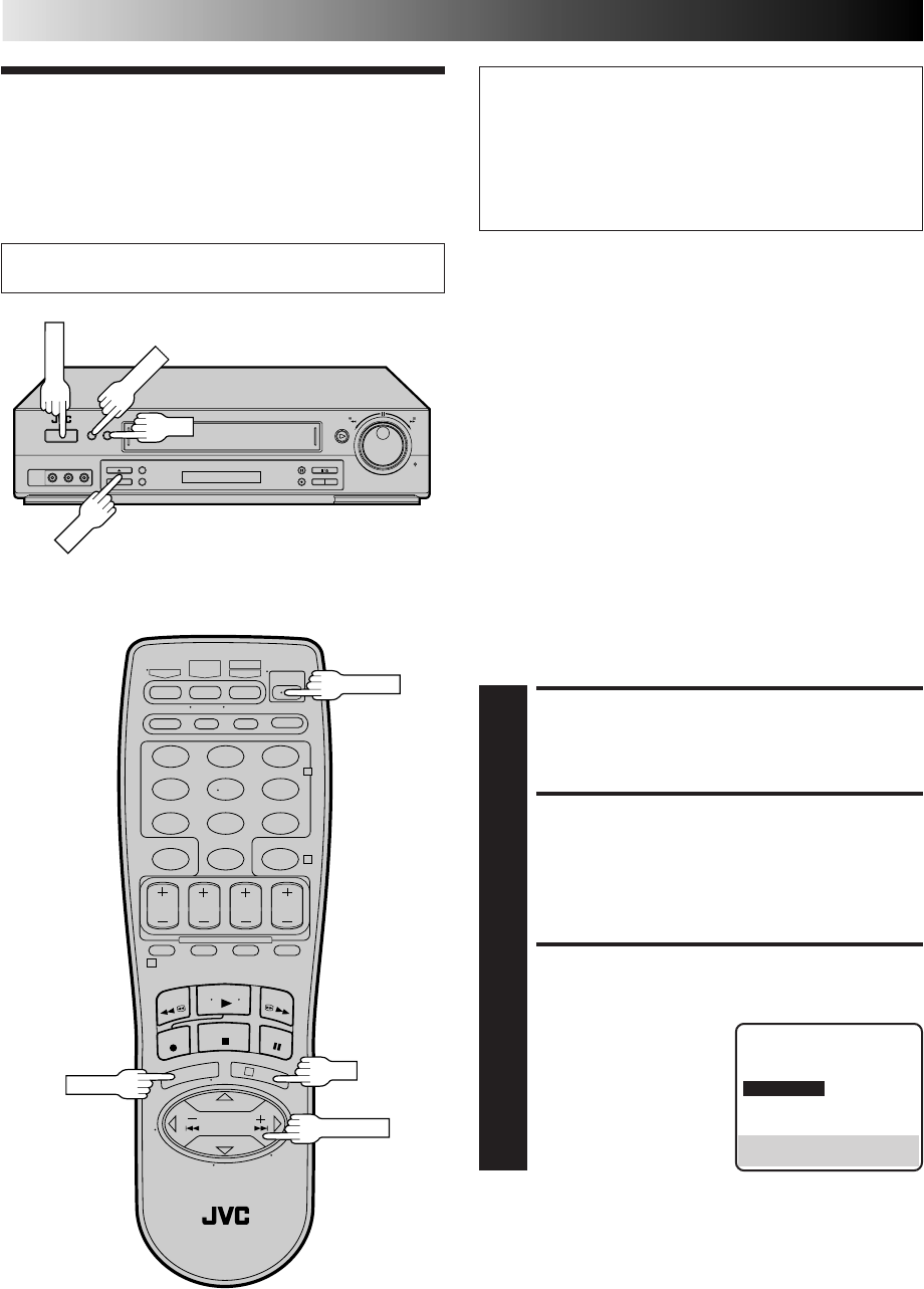
40 EN
VCR Plus+
Setup
Turn on the TV and select the VCR channel 3 or 4 (or AV
mode).
TIMER RECORDING (cont.)
IMPORTANT
If you have moved to a different area or if a broadcasting
station's channel number has been changed, the wrong VCR
or CABLE CH number will be displayed on the VCR Plus+
Program screen (Z step 5 on page 39). When this happens,
perform the following steps to set the correct the Guide
Channel number for that station.
To ensure that VCR Plus+Timer Recording operates correctly it
is necessary to set the VCR Plus+ "Guide Channel Set " for each
station. Please read the following information carefully.
VCR Plus+ Guide Channel Matching
VCR Plus+ assigns a VCR Plus+ "Guide Channel" to broadcast
and cable TV channels. These Guide Channel numbers are also
called the VCR Plus+ Channel Codes. Most TV listings have a
section, usually a chart, indicating the "Guide Channel" numbers
assigned to each station. For accurate VCR Plus+ Programming
the VCR Plus+ Guide Channel number for each station should
match the channel number on which it is received in your area.
NOTES:
●
In many instances the VCR Plus+ Guide Channel numbers for
cable and broadcast TV stations DO NOT match the channel
number on which it is received by your VCR or cable box.
Check your TV listing, or contact your cable supplier for
details.
●
Many broadcast TV stations can be viewed on cable. Check
your TV listing, or contact your cable supplier for details.
TURN ON THE VCR
1
Press POWER.
ACCESS MAIN MENU
SCREEN
2
Press MENU.
ACCESS INITIAL SET
SCREEN
3
Press CH5∞ or SHUTTLE
PLUS %fi to move the
highlight bar (arrow) to
“INITIAL SET”, then press
OK or SHUTTLE PLUS .
%
MAIN MENU
FUNCTION SET
TUNER SET
=INITIAL SET
PRESS (5,∞), THEN (OK)
PRESS (MENU) TO END
POWER
123
456
789
0
2
4
1
3
POWER
CH
OK
MENU
MENU
OK
SHUTTLE PLUS
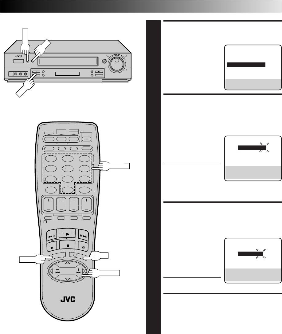
EN 41
ACCESS GUIDE CHANNEL
SET SCREEN
4
Press CH5∞ or SHUTTLE
PLUS %fi to move the
highlight bar (arrow) to
“GUIDE CHANNEL SET”,
then press OK or SHUTTLE
PLUS .
INPUT GUIDE CHANNEL
NUMBER
5
Press CH5∞, SHUTTLE
PLUS %fi or the
appropriate NUMBER keys
to input the VCR Plus+
Guide Channel number as
shown in the TV listing.
Then press OK or
SHUTTLE PLUS .
●If you receive your
channels with a cable
box and if you have
properly set your Controller, “CABLE CH” appears in
place of “VCR CH”. If not, refer to pages 16 – 18 and
re-perform the procedure.
INPUT RECEIVING CHANNEL
NUMBER
6
Press CH5∞, SHUTTLE
PLUS %fi or the
appropriate NUMBER keys
to input the number of the
channel on which the
Guide Channel’s broad-
casts are received. Then
press OK or SHUTTLE
PLUS .
●Repeat steps 5 and 6 for
each instance.
RETURN TO NORMAL
SCREEN
7
Press MENU.
(Ex.) When inputting the
Guide Channel number
6 for WNJU(Ind.)
%
(Ex.) If WNJU(Ind.) is
received on channel 47
%
GUIDE CHANNEL SET
GUIDE CH : 6
VCR CH : – – –
PRESS NUMBER KEY (0-9)
OR (5,∞), THEN (OK)
PRESS (MENU) TO END
GUIDE CHANNEL SET
=
GUIDE CH : 6
VCR CH : 47
PRESS NUMBER KEY (0-9)
OR (5,∞), THEN (OK)
PRESS (MENU) TO END
INITIAL SET
CLOCK SET
LANGUAGE ENGLISH
=GUIDE CHANNEL SET
CABLE BOX SET
DBS RECEIVER SET
SELECT WITH (5,∞) AND (OK)
PRESS (MENU) TO END
%
MENU
123
456
789
0
2
4
1
3
CH
OK
OK
MENU
NUMBER
SHUTTLE PLUS
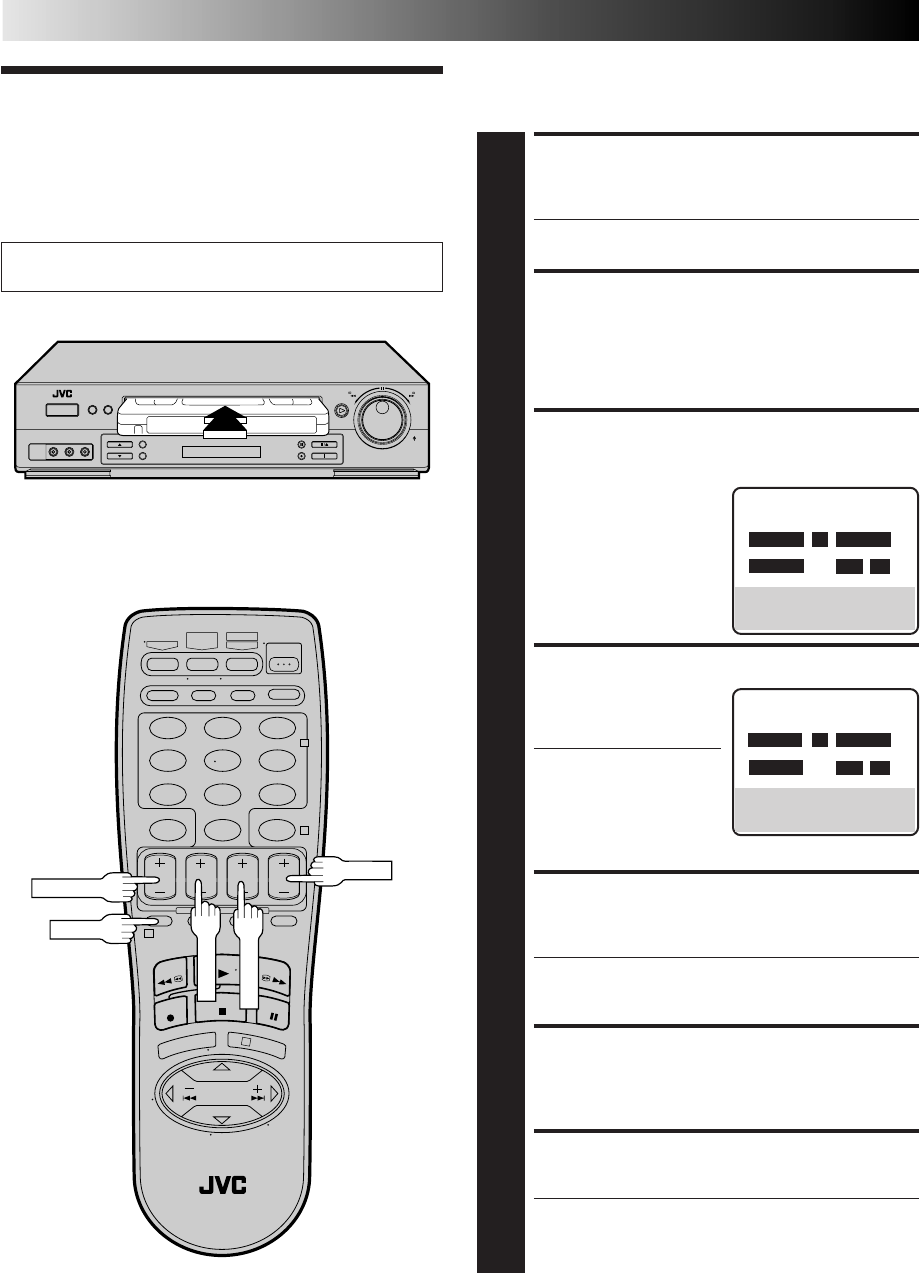
42 EN
TIMER RECORDING (cont.)
You can directly program the VCR’s timer to record up to 8
shows, as far as a year in advance. Remember, the clock must be
set before you can program the timer (Z pg. 8 or 11).
Express Timer
Programming
Turn on the TV and select the VCR channel 3 or 4 (or AV
mode).
123
456
789
0
2
4
1
3
PROG.
START+/–
STOP+/–
DATE+/–
LOAD A CASSETTE
1
Make sure the record safety tab is intact. If not, cover
the hole with adhesive tape, then load it into the VCR.
●The VCR comes on, and the counter is reset,
automatically.
ACCESS VCR PLUS+
SCREEN
2
Press PROG.
ACCESS PROGRAM
SCREEN
3
Press START +/–. (If you’re
just starting out,
“PROGRAM 1” appears.)
SET PROGRAM START TIME
4
Press START +/– to enter
the time you want
recording to start.
●Press and hold START
+/– to move in 30-
minute increments, or
press and release
repeatedly to move 1
minute at a time.
SET PROGRAM STOP TIME
5
Press STOP +/– to enter the time you want recording to
stop.
●Press and hold STOP +/– to move in 30-minute
increments, or press and release repeatedly to move 1
minute at a time.
SET PROGRAM DATE
6
Press DATE +/–. (The current date is displayed on
screen. The date you enter appears in its place.)
SET CHANNEL NUMBER
7
Press CH +/–.
●If you are using a DBS receiver, see "ATTENTION
FOR DBS RECEIVER USERS" on next page.
●Holding down CH +/– rapidly scans through the
channels.
PROGRAM 1
START STOP
8:00 AM =– –:– –AM
DATE CH
– –/– –/– – – – – SP
PRESS (+/–, SP/EP, 8=DAILY,
9=WEEKLY), THEN (0K)
PRESS (PROG.) TO END
PROGRAM 1
START STOP
– –:– –AM =– –:– –AM
DATE CH
– –/– –/– – – – – SP
PRESS (+/–, SP/EP, 8=DAILY,
9=WEEKLY), THEN (0K)
PRESS (PROG.) TO END
CH+/–
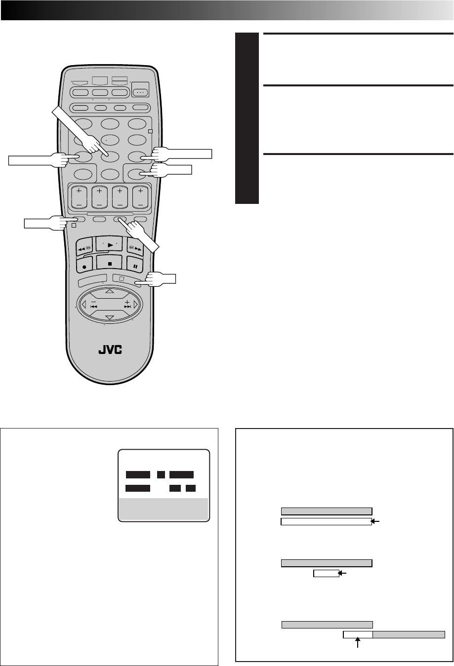
EN 43
123
456
789
0
2
4
1
3
OK
NUMBER "9"
NUMBER "8"
TIMER
NUMBER "7"
SP/EP
SET TAPE SPEED
8
Press SP/EP to set the tape speed.
RETURN TO NORMAL
SCREEN
9
Press PROG. or OK. "PROGRAM COMPLETED"
appears on the screen for about 5 seconds, then normal
screen appears.
ENGAGE TIMER MODE
10
Press TIMER. The VCR turns off automatically and "‰"
is displayed on the display panel.
PROG.
To Timer-Record Weekly Or Daily Serials . . .
. . . anytime during steps 3 through 9, press WEEKLY (NUMBER
key “9”) for weekly serials or DAILY (NUMBER key “8”) for
daily serials (Monday–Friday). Either "WEEKLY" or "DAILY"
appears on the screen. Pressing the button again makes the
corresponding indication disappear.
NOTES:
●
To disengage the timer before recording starts, press TIMER
again. Pressing once more re-engages it.
●
In case of a power failure after programming, the VCR’s memory
backup keeps your selections for approximately 10 minutes.
●
Programs that start after midnight must have the next day’s date.
●
After timer recording is completed, the VCR’s power goes off
automatically.
●
You can program the timer while a regular recording is in
progress; the on-screen menu will not be recorded.
●
If the end of tape is reached during timer recording, the
cassette is automatically ejected.
●
When timer-recording cable or satellite channels through an
external tuner, be sure to keep the cable box or satellite
receiver's power ON.
10:00 11:00 12:00
ATTENTION
If there is a conflict in the timer schedule and one program
overlaps with another, only the parts shown below in gray
will be recorded.
Pattern 1: The program with the lower program number
will be recorded.
Pattern 2: The program that is broadcast earlier will be
recorded.
Pattern 3: The program that is broadcast earlier will be
recorded, followed by the remaining portion of
the other program.
CH10
CH40 Not recorded
Program 1
Program 2
10:00 11:00 12:00
CH10
Program 2 Not recorded
Program 1
CH40
10:00 11:00 12:00
CH10
CH40
Program 1 Program 2
Not recorded
ATTENTION FOR DBS RECEIVER USERS
If you are using a DBS receiver
(unless "DBS RECEIVER SET" is
set to "OFF" Z pg. 20), the
BAND indication (TV or CATV
or DBS) appears under the
channel number display. If the
channel number that has been
entered requires that the band
be set, "7=DBS" is displayed
on the screen. Press the NUMBER key "7" to select the
desired band.
a– TV : To timer-record a regular TV program received
on the VCR.
b– CATV : To timer-record a cable TV program received on
the VCR, or through a cable box (unless "CABLE
BOX SET" is set to "OFF" Z pg.17).
c– DBS : To timer-record a satellite program received
through a DBS receiver.
●If "BAND" is set to "TV" at the Tuner Set screen (Z pg.14)
and "CABLE BOX SET" is set to "OFF" at the Cable Box
Set screen (Zpg. 17), CATV will not be displayed on the
Program screen; If "BAND" is set to "CATV" or "CABLE
BOX SET" is set to "ON", TV will not be displayed.
PROGRAM 1
START STOP
8:00AM =9:00PM
DATE CH
12/24/98 110 SP
THU DBS
PRESS (+/–, SP/EP, 8=DAILY,
9=WEEKLY, 7=DBS), THEN (0K)
PRESS (PROG.) TO END
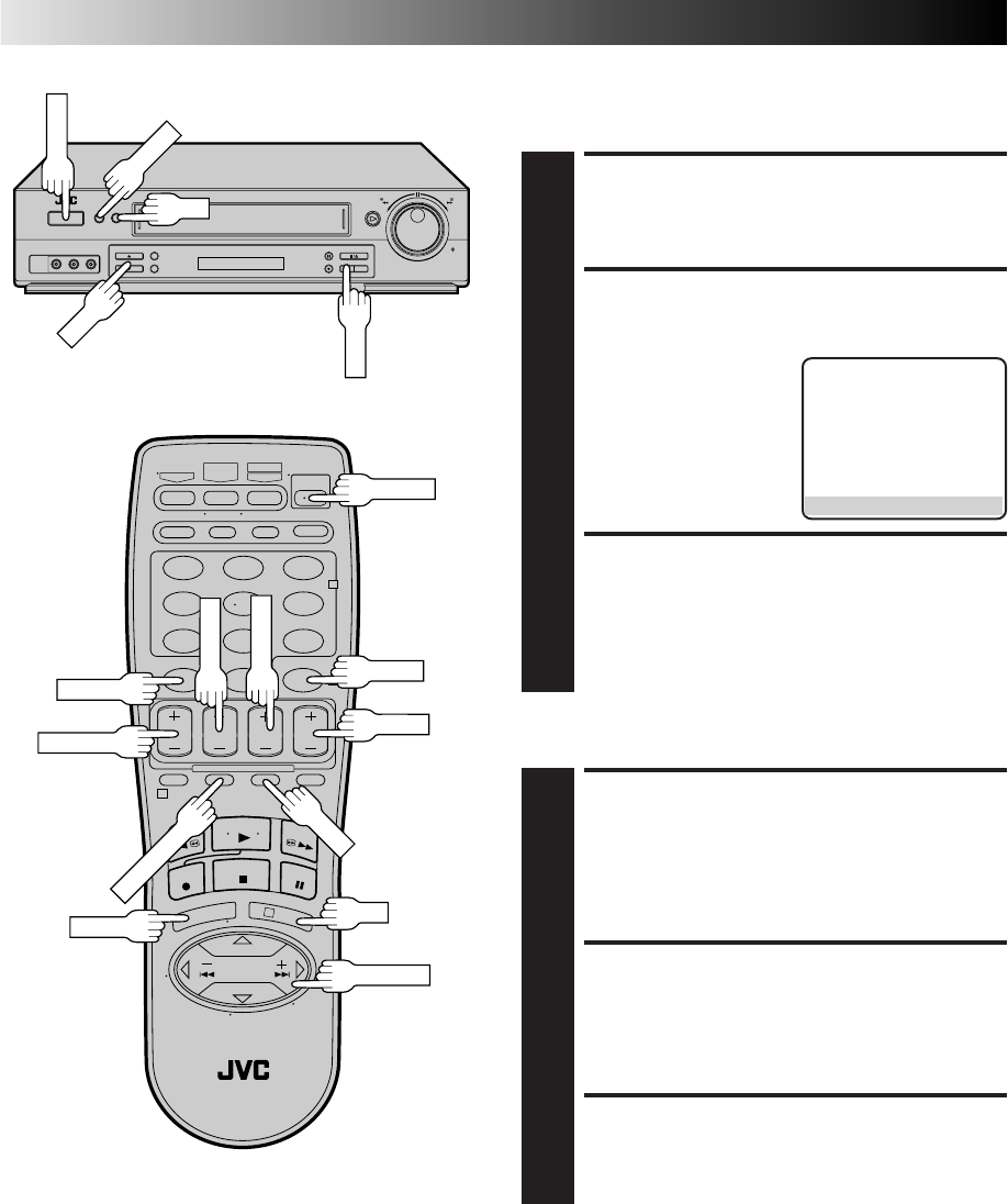
44 EN
123
456
789
0
2
4
1
3
TIMER RECORDING (cont.)
Check, Cancel And Revise
Programs
DISENGAGE TIMER
1
Press TIMER, then press POWER.
ACCESS PROGRAM
CHECK SCREEN
2
Press PROG. CHECK.
ACCESS PROGRAM
SCREEN
3
Press PROG. CHECK again to check more information.
Each time you press PROG. CHECK, the next program's
information appears.
PR START STOP CH DATE
1 8:00P 10:00 12 12/24
2 10:00A 10:45 40 12/25
3 11:30P 01:00 125 12/25
4
5
6
7
8
PRESS (CHECK) TO NEXT
CANCEL OR REVISE A
PROGRAM
4
To cancel a program, press CANCEL at the appropriate
program screen.
To revise a program, press the appropriate button:
START+/–, STOP+/–, DATE+/–, CH+/–, SP/EP.
RETURN TO NORMAL
SCREEN
5
Press PROG. CHECK as many times as necessary. If
there are still programs remaining, go to step 6.
RE-ENGAGE TIMER
6
Press TIMER.
To Cancel Or Revise A Program...
TIMER
PROG. CHECK
CH+/–
CANCEL
START+/–
STOP+/–
DATE+/–
SP/EP
POWER
CH
OK
MENU
POWER
MENU
OK
SP/EP
SHUTTLE PLUS
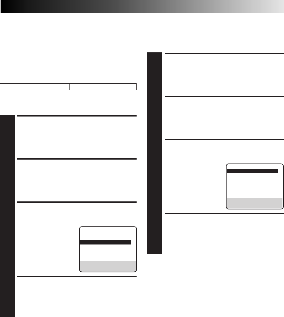
EN 45
ACCESS MAIN MENU
SCREEN
1
Press MENU.
ACCESS FUNCTION SET
SCREEN
2
Move the highlight bar (arrow) to "FUNCTION SET" by
pressing CH5∞ or SHUTTLE PLUS %fi, then press OK
or SHUTTLE PLUS .
SELECT AUTO TIMER SET
MODE
3
Move the highlight bar
(arrow) to "AUTO TIMER"
by pressing CH5∞ or
SHUTTLE PLUS %fi, then
press OK or SHUTTLE
PLUS to set to "ON" or
"OFF".
RETURN TO NORMAL
SCREEN
4
Press MENU.
Auto Timer
When the Auto Timer is set to ON the timer is automatically
engaged when the VCR's power is turned off. It is automatically
disengaged when the VCR is powered back on.
Auto SP→EP Timer
If, when recording in SP mode, there is not enough tape to record
the entire program, the VCR automatically switches to EP mode
to allow complete recording. This feature is especially handy
when recording a program of more than 2 hours in length.
For Example . . .
Recording a program of 140 minutes in length onto a 120-
minute tape
Make sure you set "AUTO SP→EP TIMER" to “ON” at the
Function screen before the timer recording starts.
Approximately 110 minutes
SP mode
Approximately 30 minutes
EP mode
Total 140 minutes
ACCESS MAIN MENU
SCREEN
1
Press MENU.
ACCESS FUNCTION SET
SCREEN
2
Move the highlight bar (arrow) to "FUNCTION SET" by
pressing CH 5∞ or SHUTTLE PLUS %fi, then press OK
or SHUTTLE PLUS .
SELECT AUTO SP→EP
TIMER SET MODE
3
Move the highlight bar
(arrow) to "AUTO SP→EP
TIMER" by pressing CH
5∞ or SHUTTLE PLUS
%fi, then press OK or
SHUTTLE PLUS to set to
"ON".
RETURN TO NORMAL
SCREEN
4
Press MENU.
%
%
%
NOTES:
●
If you have programmed the VCR to timer-record 2 or more
programs, the second program and those thereafter may not
fit on the tape if you set the Auto SP
→
EP Timer mode to
"ON". In this case, make sure the mode is not engaged, then
set the tape speed manually during timer programming.
●
In order to ensure that the recording fits on the tape, this
feature may leave a slight non-recorded section at the end of
the tape.
●
There may be some noise at the point on the tape where the
VCR switches from SP to EP mode.
●
The Auto SP
→
EP Timer feature is not available during ITR
(Instant Timer Recording), and the feature will work with the
following tapes: T(ST)-30, T(ST)-60, T(ST)-90, and T(ST)-120.
%
NOTE:
For safety, when AUTO TIMER is set to “OFF”, all other VCR
functions are disabled while the Timer mode is engaged. To
disengage the timer, press TIMER.
FUNCTION
AUTO TIMER OFF
SUPERIMPOSE ON
=AUTO SP=EP TIMER ON
VIDEO STABILIZER OFF
2ND AUDIO RECORD OFF
AUDIO MONITOR HI-FI
NEXT PAGE
SELECT WITH (5,∞) AND (OK)
PRESS (MENU) TO END
FUNCTION
=AUTO TIMER OFF
SUPERIMPOSE ON
AUTO SP=EP TIMER OFF
VIDEO STABILIZER OFF
2ND AUDIO RECORD OFF
AUDIO MONITOR HI-FI
NEXT PAGE
SELECT WITH (5,∞) AND (OK)
PRESS (MENU) TO END
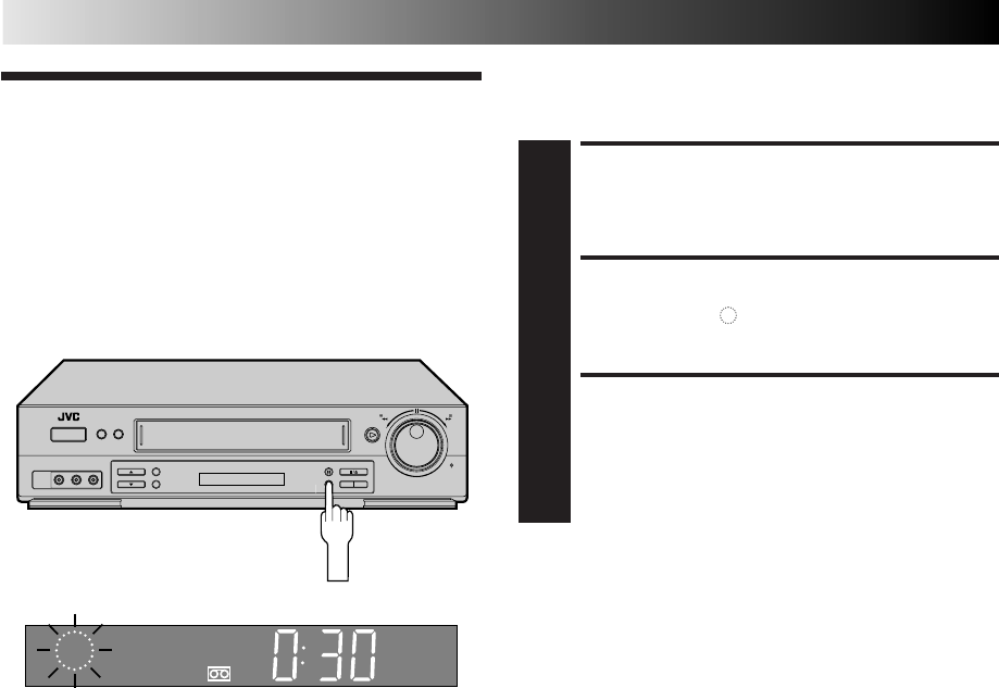
46 EN
Instant Timer
Recording
(ITR)
This easy method lets you record from 30 minutes to 6 hours
(selectable in 30-min. increments) and shuts the VCR off after
recording is finished.
START RECORDING
1
Press REC on the front panel.
ENGAGE ITR MODE
2
Press REC again. " " blinks and 0:30 appears on the
front display panel.
SET RECORDING
DURATION
3
If you want to record for more than 30 minutes, press
REC to extend the time. Each press extends recording
time by 30 minutes.
NOTES:
●
You can only perform ITR using the REC button on the VCR's
front panel.
●
After you set the ITR time, the previous display reappears.
●
To check the remaining time, press REC once during record-
ing and the remaining time will be displayed for about 5
seconds. Be careful not to press REC again within these 5
seconds, or you will round the recording time up to the next
30 minute increment.
TIMER RECORDING (cont.)
REC
SP VCR
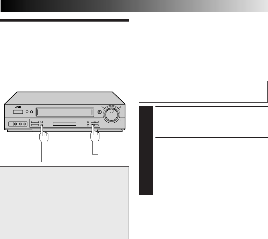
EN 47
This facility allows you to automatically record a satellite
program which is timer-programmed on your external satellite
receiver. Connect a satellite receiver to the VCR's rear AUDIO/
VIDEO IN or S VIDEO IN* (L-1) connectors and program the
timer on the satellite receiver; the VCR starts recording when the
signals input from the satellite receiver to the rear AUDIO/VIDEO
IN or S VIDEO IN (L-1) connectors, and when there is no input
signals the VCR stops recording and the power shuts off.
* If you have connected the satellite receiver to the VCR's
S VIDEO IN connector, set "REAR AUX INPUT" to "S-VIDEO"
at the Function screen (Z pg. 49 – 50).
Automatic Sat-
ellite Program
Recording
ATTENTION
●Be sure not to turn on the satellite receiver before the
program is executed; otherwise, the VCR will start
recording when the satellite receiver's power is turned on.
●If you have connected another appliance other than a
satellite receiver to the rear AUDIO/VIDEO IN or S
VIDEO IN (L-1) connectors, be sure not to engage the
Auto Satellite Prog Rec mode; otherwise, the VCR will
start recording when the connected appliance's power is
turned on.
●Auto Satellite Prog recording and timer-recording cannot
be done at the same time.
Before performing the following steps:
●Program the timer on the satellite receiver.
●Insert a cassette with the safety tab in place.
SET TAPE SPEED
1
Press SP/EP to set the tape speed.
ENGAGE AUTO SATELLITE
PROG REC MODE
2
Press and hold REC LINK for about 2 seconds. The
button lights up and the VCR turns off automatically.
●To disengage the Auto Satellite Prog Rec mode, press
REC LINK. The button's light goes off.
●If the VCR's power is off, it is not possible to engage
the Auto Satellite Prog Rec mode.
NOTES:
●
Auto Satellite Prog recording is not possible with the front AUDIO/VIDEO IN (F-1) connectors.
●
When the Auto Satellite Prog Rec mode is engaged or the VCR's power is turned off after Auto Satellite Prog recording is finished,
the VCR will not enter the Timer mode even though "AUTO TIMER" is set to "ON".
●
For timer programming of the satellite receiver, refer to the instruction manual of the satellite receiver.
●
Auto Satellite Prog recording is not possible if your satellite receiver does not have a timer.
●
The REC LINK button's light blinks while Auto Satellite Prog recording is in progress.
●
Pressing the VCR's POWER button while Auto Satellite Prog recording is in progress turns off the VCR's power and disengages the
Auto Satellite Prog Rec mode.
●
If there is more than one satellite program you wish to record with Auto Satellite Prog Recording, it is not possible to set a different
tape speed for each; the tape speed selected in step 1 will apply to all the programs for Auto Satellite Prog recording.
●
The Active Video Calibration (
Z
pg. 32) does not work while Auto Satellite Prog recording is in progress.
●
Auto Clock (
Z
pg. 9) does not work when the Auto Satellite Prog Rec mode is engaged.
●
Depending on the type of satellite receiver, the VCR may not record a short portion at the beginning of the program or may record
slightly longer than the actual length of the program.
●
If you engage the Auto Satellite Prog Rec mode when the satellite receiver's power is on, the VCR will not start Auto Satellite Prog
recording even though the REC LINK button's light blinks. When the satellite receiver shuts off once and is turned back on again,
the VCR starts recording.
●
You can also record a program from your cable system in the same way if the system has a timer and is connected to the VCR's
rear AUDIO/VIDEO IN or S VIDEO IN (L-1) connectors.
●
When you press the VCR's REC LINK button to engage the Auto Satellite Prog Rec mode, if the REC LINK button does not light but
instead blinks quickly even though your satellite receiver's power is off, Auto Satellite Prog Recording will not work properly with
that satellite receiver*.
If this is the case, perform "Express Timer Programming" (
Z
pg. 42) to timer-record a satellite program.
* Some satellite receivers output signals even if the power is off. Auto Satellite Prog Recording is not possible with those satellite receivers.
REC LINK
SP/EP
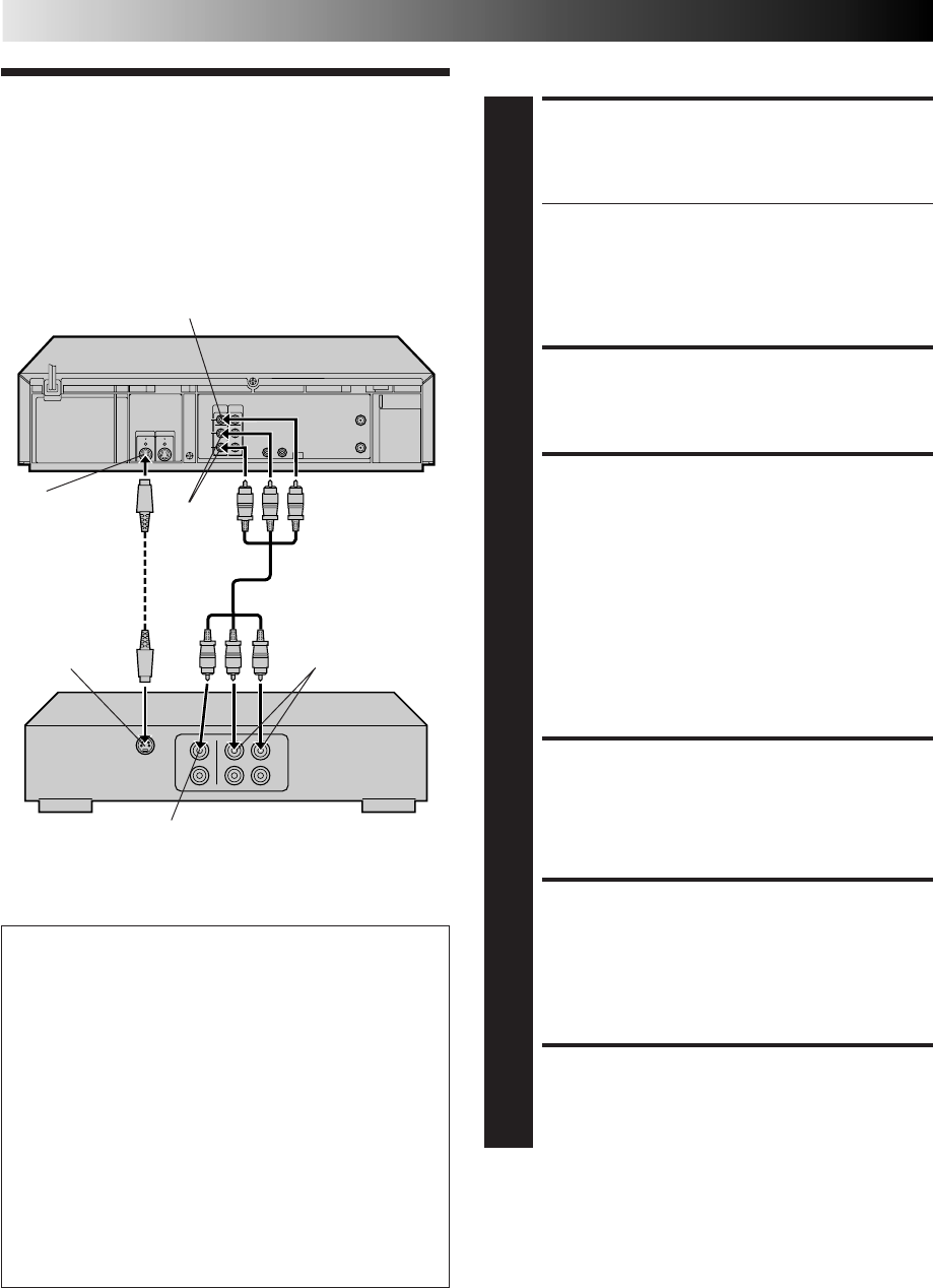
48 EN
EDITING
Edit To Or
From Another
VCR
You can use your VCR as the player or the recorder.
MAKE CONNECTIONS
1
Connect an AV cable between the player’s VIDEO OUT
and AUDIO OUT connectors and the recorder’s VIDEO
IN and AUDIO IN connectors.
●If using another VCR with an S-VIDEO input or
output connector, it is recommended to use the S-
VIDEO connection to minimize picture degradation
while editing.
●When using your VCR as the recorder and a monaural
VCR as the player, connect the player’s AUDIO OUT
connector to the AUDIO IN L connector on the recorder.
LOAD CASSETTES
2
Insert the playback cassette into the player and the
cassette to be recorded on into the recorder.
SET RECORDER’S INPUT
MODE
3
Set to "AUX". With this VCR, press the NUMBER key "0"
and/or CH to select depending on the connector being
used – "L-1" for the rear AUDIO/VIDEO IN connector,
or "F-1" for the front AUDIO/VIDEO IN connector.
NOTE:
If you use your VCR as the recorder and have connected
another VCR to your VCR's S-VIDEO IN connector, you
need to set "REAR AUX INPUT" to "S-VIDEO" at the
Function screen. Follow steps 4 – 6 from the "Edit From
A Camcorder" section (
Z
pg. 49 – 50).
ENGAGE TAPE DUBBING
MODE
4
Follow steps 12 – 14 from the "Edit From A Camcorder"
section (Z pg. 50).
START PLAYER
5
Set to its play mode.
NOTE:
If the player is equipped with a superimpose/OSD
disable feature then set "SUPERIMPOSE" to OFF before
pressing PLAY (
Z
pg. 28).
START RECORDER
6
Set to its record mode.
Recorder Another VCR
AUDIO IN
Audio/Video cable
(supplied)
VIDEO IN
Player Your VCR
VIDEO OUT
AUDIO
OUT
Advantages Of S-VHS Editing
S-VHS allows you make high resolution video recordings
when dubbing from one VCR to another.
You can edit from VHS to S-VHS, from S-VHS to VHS, or
from S-VHS to S-VHS.
●From VHS to S-VHS (VIDEO-VIDEO connection): Record
VHS playback signals in the S-VHS mode. Although the
picture quality is inherently limited by the orignal VHS
source material, the edited tape has better picture quality
than those made by VHS-to-VHS editing.
●From S-VHS to VHS (VIDEO-VIDEO connection): Because
the picture quality of the source material is very high, the
edited tape has better picture quality than those made by
VHS-to-VHS editing.
●From S-VHS to S-VHS (S-VIDEO connection): A high
resolution copy is made of a high resolution original S-
VHS tape with minimal picture degradation. This is the
preferred method of video dubbing.
S-Video cable
(supplied)
NOTES:
●
Be sure to set "TAPE DUB MODE" back to "OFF" when you
finish editing.
●
When "TAPE DUB MODE" is set to "ON" Active Video
Calibration is deactivated in order to provide better picture
quality edits.
●
If you use an auxiliary input to connect a cable box or DBS
receiver make sure that the correct input ("L-1", "F-1" or "S-
VIDEO") is selected after you have finished editing (
Z
step 6,
page 49).
S VIDEO OUT
S VIDEO IN
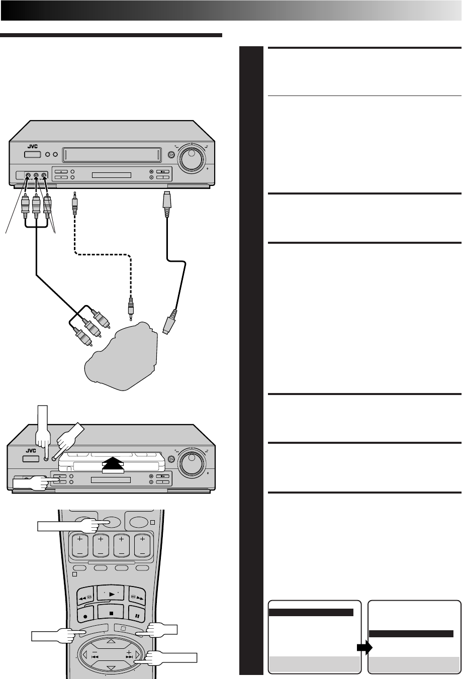
EN 49
04
1
3
Edit From A
Camcorder
You can use a camcorder as the player and your VCR as the recorder.
MAKE CONNECTIONS
1
Connect an AV cable between the camcorder’s VIDEO
OUT and AUDIO OUT connectors and your VCR’s
VIDEO IN and AUDIO IN connectors.
●If connecting a camcorder with an S-VIDEO output
connector, it is recommended to use the S-VIDEO
connection to minimize picture degradation while editing.
●When a Master Edit Control-equipped JVC camcorder is
used, the camcorder is capable of controlling your VCR.
The mini-plug cable is a mono 3.5 mm mini-plug to
mono 3.5 mm mini-plug connector.
●If connecting to a camcorder with a monaural output,
connect the audio output connector on the
camcorder to AUDIO IN L of the VCR.
LOAD A CASSETTE
2
Insert the cassette to be recorded on into the recorder.
SET RECORDER’S INPUT MODE
3
Set to "AUX". Press the NUMBER key “0” and/or CH to
select depending on the connector being used – "L-1"
for the rear AUDIO/VIDEO IN connector, or "F-1" for
the front AUDIO/VIDEO IN connector.
If you have connected a JVC Master Edit Control-
equipped camcorder to...
... the VCR's rear panel S-VIDEO IN and AUDIO IN
connectors — step 4
... the VCR's rear panel VIDEO IN and AUDIO IN
connectors — step 4
... the VCR's front panel VIDEO IN and AUDIO IN
connectors — step 8
If you are not using a JVC Master Edit Control-equipped
camcorder — step 12
ACCESS MAIN MENU SCREEN
4
Press MENU.
ACCESS FUNCTION SET SCREEN
5
Press CH 5∞ or SHUTTLE PLUS %fi to move the
highlight bar (arrow) to “FUNCTION SET”, then press
OK or SHUTTLE PLUS .
SELECT REAR AUX INPUT SET
MODE
6
a– S-VHS IN: Move the highlight bar (arrow) to
"REAR AUX INPUT" by pressing CH 5∞ or
SHUTTLE PLUS %fi, then press OK or SHUTTLE
PLUS to set to "S-VIDEO".
b– REAR VIDEO: Move the highlight bar (arrow) to
"REAR AUX INPUT" by pressing CH 5∞ or
SHUTTLE PLUS %fi, then press OK or SHUTTLE
PLUS to set to "VIDEO".
NUMBER "0"
Recorder Your VCR
To rear panel
REMOTE PAUSE/AV
COMPULINK
connector
Mini-plug cable
(not supplied)
(JVC camcorder
only)
Audio/Video
cable
(supplied)
Camcorder
VIDEO OUT
AUDIO
OUT EDIT
VIDEO
IN AUDIO
IN
CH
OK
OK
MENU
MENU
%
SHUTTLE PLUS
S-VIDEO
IN
S-VIDEO
OUT
S-VIDEO
cable
(supplied)
Player
%
PREVIOUS PAGE
S-VHS MODE AUTO
AV COMPU-LINK ON
VIDEO CALIBRATION ON
=REAR AUX INPUT S-VIDEO
TAPE DUB MODE ON
SELECT WITH (5,∞) AND (OK)
PRESS (MENU) TO END
FUNCTION
=AUTO TIMER OFF
SUPERIMPOSE ON
AUTO SP=EP TIMER OFF
VIDEO STABILIZER OFF
2ND AUDIO RECORD OFF
AUDIO MONITOR HI-FI
NEXT PAGE
SELECT WITH (5,∞) AND (OK)
PRESS (MENU) TO END
%
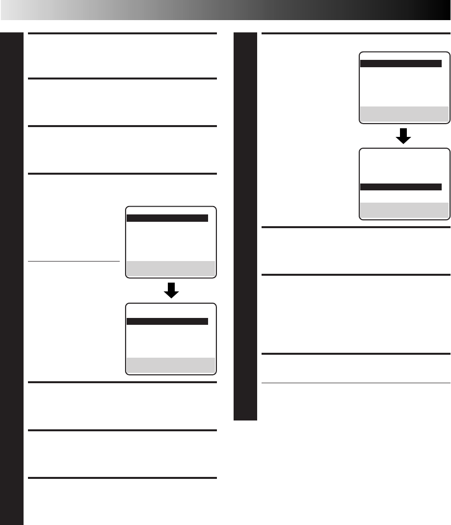
50 EN
RETURN TO NORMAL SCREEN
7
Press MENU.
ACCESS MAIN MENU SCREEN
8
Press MENU.
ACCESS FUNCTION SET SCREEN
9
Press CH 5∞ or SHUTTLE PLUS %fi to move the
highlight bar (arrow) to “FUNCTION SET”, then press OK
or SHUTTLE PLUS .
ENABLE REMOTE PAUSE
FUNCTION
10
Press CH 5∞ or SHUTTLE
PLUS %fi to move the
highlight bar (arrow) to
"AV COMPU-LINK", then
press OK or SHUTTLE
PLUS to set to "OFF".
●The REMOTE PAUSE/AV
COMPU-LINK connec-
tor works as the AV
Compulink Playback
connector when "AV
COMPU-LINK" is set to
"ON" (Z pg. 31), and
works as the Remote
Pause connector when
"AV COMPU-LINK" is
set to "OFF".
RETURN TO NORMAL SCREEN
11
Press MENU.
ACCESS MAIN MENU SCREEN
12
Press MENU.
ACCESS FUNCTION SET SCREEN
13
Press CH 5∞ or SHUTTLE PLUS %fi to move the
highlight bar (arrow) to “FUNCTION SET”, then press OK
or SHUTTLE PLUS .
FUNCTION
=AUTO TIMER OFF
SUPERIMPOSE ON
AUTO SP=EP TIMER OFF
VIDEO STABILIZER OFF
2ND AUDIO RECORD OFF
AUDIO MONITOR HI-FI
NEXT PAGE
SELECT WITH (5,∞) AND (OK)
PRESS (MENU) TO END
EDITING (cont.)
%
%
SELECT TAPE DUB MODE
14
Move the highlight bar
(arrow) to "TAPE DUB
MODE" by pressing CH
5∞ or SHUTTLE PLUS %fi,
then press OK or SHUTTLE
PLUS to set to "ON".
RETURN TO NORMAL SCREEN
15
Press MENU.
START PLAYER
16
Set the camcorder to its play mode.
NOTE:
If the camcorder is equipped with a superimpose/OSD
disable feature then set its superimpose or display
feature to OFF before pressing play.
START RECORDER
17
Set your VCR to its record mode.
●If you are using a Master Edit Control-equipped JVC
camcorder, it can put the recorder automatically into
Record mode. (Refer to camcorder's instruction
manual.)
NOTES:
●
Be sure to set "TAPE DUB MODE" back to "OFF" when you
finish editing.
●
When "TAPE DUB MODE" is set to "ON" Active Video
Calibration is deactivated in order to provide better picture
quality edits.
●
If you use an auxiliary input to connect a cable box or DBS
receiver make sure that the correct input ("L-1", "F-1" or
"S-VIDEO") is selected after you have finished editing (
Z
step
3, 6, pg. 49).
PREVIOUS PAGE
S-VHS MODE AUTO
=AV COMPU-LINK OFF
VIDEO CALIBRATION ON
REAR AUX INPUT VIDEO
TAPE DUB MODE ON
SELECT WITH (5,∞) AND (OK)
PRESS (MENU) TO END
FUNCTION
=AUTO TIMER OFF
SUPERIMPOSE ON
AUTO SP=EP TIMER OFF
VIDEO STABILIZER OFF
2ND AUDIO RECORD OFF
AUDIO MONITOR HI-FI
NEXT PAGE
SELECT WITH (5,∞) AND (OK)
PRESS (MENU) TO END
PREVIOUS PAGE
S-VHS MODE AUTO
AV COMPU-LINK ON
VIDEO CALIBRATION ON
REAR AUX INPUT VIDEO
=TAPE DUB MODE ON
SELECT WITH (5,∞) AND (OK)
PRESS (MENU) TO END
%
%
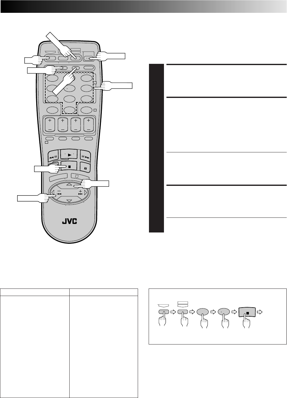
EN 51
SPECIAL FEATURES
123
456
789
0
2
4
1
3
TV Multi-Brand Remote
Control
The VCR's remote control can control several functions on JVC
remote control TVs and on the brands of remote control TVs
listed below. *The default setting is JVC code 01.
TURN ON THE TV
1
Turn the power on using the TV's remote control.
SET TV BRAND CODE
2
Refer to the chart in the left column. While holding down
TV on the VCR's remote control, press MBR SET and enter
your TV’s brand code using the NUMBER keys, then press
STOP.
Follow the example shown below.
The TV's power should go off. If it does, try other
operations (Z step 3).
●Once you have set the remote control to operate the
TV, you don’t have to repeat this step until you
replace your remote control’s batteries.
●PANASONIC has two codes. If the TV does not
function with one code, try entering the other.
OPERATE TV
3
First, while holding down TV, press the corresponding
button: POWER, TV CH +/–, TV/VCR, TV VOL +/–,
NUMBER keys.
●For some brands of TV, you must press ENTER after
having pressed the NUMBER keys.
POWER
TV
NUMBER
TV/VCR
MBR SET
ENTER
TV VOL +/–
TV BRAND NAME BRAND CODE
JVC 01
MAGNAVOX 02
MITSUBISHI 03
PANASONIC 04, 11
RCA 05
SHARP 06
SONY 07
TOSHIBA 08
ZENITH 09
HITACHI 10
SAMSUNG 12
SANYO 13
SEARS 13
(Ex.) To set remote control to RCA 05:
Press in succession
TV MBRSET
A/B
5
STOP
0
Hold
down
Release
NOTE:
Depending on the type of TV, there may be cases where some
or all functions cannot be operated using the remote control.
STOP
TV CH+/–
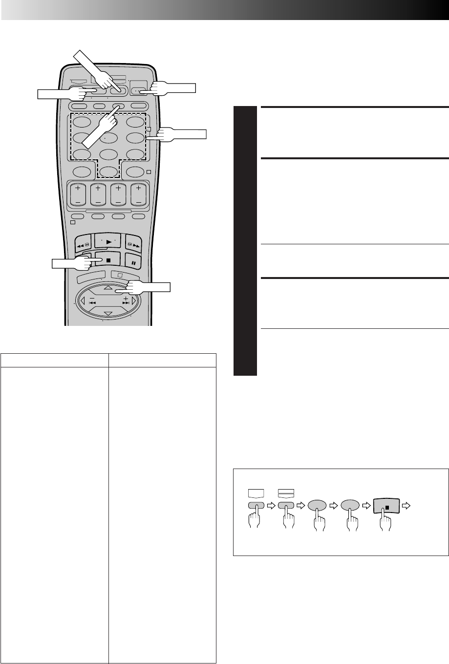
52 EN
SPECIAL FEATURES (cont.)
Cable Box Multi-Brand
Remote Control
The VCR's remote control can control functions on the brands
of cable boxes listed below. Some cable box brands have more
than one code. If your cable box does not function with a
specified code, try other codes.
TURN ON THE CABLE BOX
1
Turn the power on using the cable box’s remote control.
ENTER CABLE BOX BRAND
2
While holding down CABLE/DBS on the VCR's remote
control, press MBR SET and use the NUMBER keys to
enter the cable box brand number from the chart in the
left column and then press STOP.
Follow the example shown below.
The cable box's power should go off. If it does, try other
operations (Z step 3).
●Once you have set the remote control to operate the
cable box, you don't have to repeat this step until you
replace the remote control's batteries.
OPERATE CABLE BOX
3
First, while holding down CABLE/DBS, press the
corresponding button: POWER, TV CH +/–, NUMBER
keys.
●For some brands of cable box, you must press ENTER
after having pressed the NUMBER keys.
●To change the cable box's channel, press TV CH +/–
or the NUMBER keys. (The CH +/– button can be
used to change the VCR's channel only.)
123
456
789
0
2
4
1
3
POWER
CABLE/DBS
MBR SET
STOP
ENTER
NUMBER
CABLE BOX BRAND NAME BRAND CODE
ARCHER 01, 05, 17
CABLETENNA 01, 17
CABLEVIEW 15, 16, 17, 21, 25
CITIZEN 15, 16, 17, 21, 25
CURTIS 02
DIAMOND 01, 17
EASTERN 19
GC BRAND 15, 16, 17, 21, 25
GEMINI 15
GENERAL INSTRUMENTS 01, 04, 06, 11, 12, 15
HAMLIN 10, 18, 19, 23
JASCO 15
JERROLD 01, 04, 06, 11, 12, 15
NOVAVISION 02
OAK 07
PANASONIC 13, 14
PULSER 15, 16, 17, 21, 25
RCA 13, 14
REGAL 10, 18, 19, 23
REGENCY 19
REMBRANDT 01, 16, 17
SAMSUNG 05, 16, 24
SCIENTIFIC ATLANTA 02
SIGMA 07
SL MARX 05, 16, 17, 24, 25
SPRUCER 13, 14
STARGATE 05, 15, 16, 17, 21, 24, 25
TELEVIEW 05, 16, 24
TOCOM 01, 04, 16
UNIKA 01, 17
UNIVERSAL 16, 17, 25
VIDEOWAY 03, 09, 22
ZENITH 03, 09, 22
NOTES:
●
Depending on the type of cable box, there may be cases
where some or all functions cannot be operated using the
remote control.
●
It's not possible to set the remote control for both your cable
box and a DBS receiver at the same time. You can only set the
remote control to operate one of these units at a time.
(Ex.) To set remote control to RCA 14:
Hold
down Press in succession
CABLE/
DBS MBRSET
A/B
4
STOP
1
Release
TV CH+/–
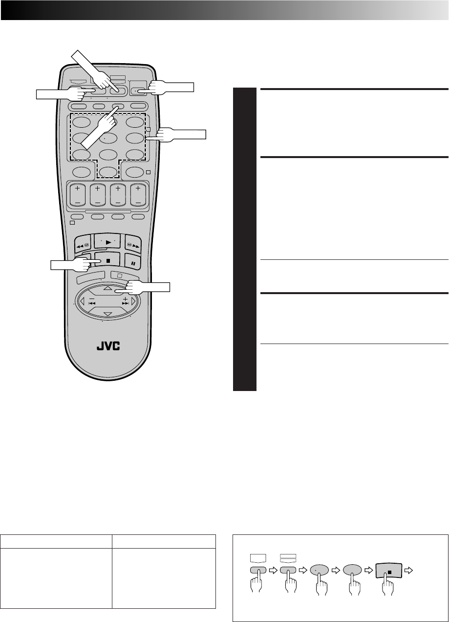
EN 53
DBS Receiver Multi-Brand
Remote Control
The VCR's remote control can control functions on the brands
of DBS (Direct Broadcast Satellite) receivers listed below.
123
456
789
0
2
4
1
3
TURN ON THE DBS
RECEIVER
1
Turn the power on using the DBS receiver's remote
control.
ENTER DBS RECEIVER
BRAND
2
While holding down CABLE/DBS on the VCR’s remote
control, press MBR SET and use the NUMBER keys to
enter the DBS receiver brand number from the chart in
the left column and then press STOP.
Follow the example shown below.
The DBS receiver's power should go off. If it does, try
other operations (Z step 3).
●Once you have set the remote control to operate the
DBS receiver, you don't have to repeat this step until
you replace the remote control's batteries.
OPERATE DBS RECEIVER
3
First, while holding down CABLE/DBS, press the
corresponding button: POWER, TV CH +/–, NUMBER
keys.
●Depending on the DBS receiver you may have to
press ENTER after having pressed the NUMBER keys.
●To change the DBS receiver's channel, press TV CH
+/– or the NUMBER keys. (The CH +/– button can be
used to change the VCR's channel only.)
POWER
CABLE/DBS
MBR SET
ENTER
STOP
NUMBER
DBS BRAND NAME BRAND CODE
JVC (DISH Network) 51
ECHOSTAR (DISH Network) 51
PRIMESTAR 50
SONY (DSS) 41
RCA (DSS) 40
NOTES:
●
Depending on the type of DBS receiver, there may be cases
where some or all functions cannot be operated using the
remote control.
●
It's not possible to operate a DBS receiver that is not
equipped with a remote control sensor.
●
Though ECHOSTAR has a number of different remote codes,
this remote control is applicable only to one of those codes
preset at the factory.
●
It's not possible to set the remote control for both your DBS
receiver and a cable box at the same time. You can only set
the remote control to operate one of these units at a time.
(Ex.) To set remote control to JVC 51:
5
CABLE/
DBS MBRSET
A/B
1
STOP
Release
Hold
down Press in succession
TV CH+/–
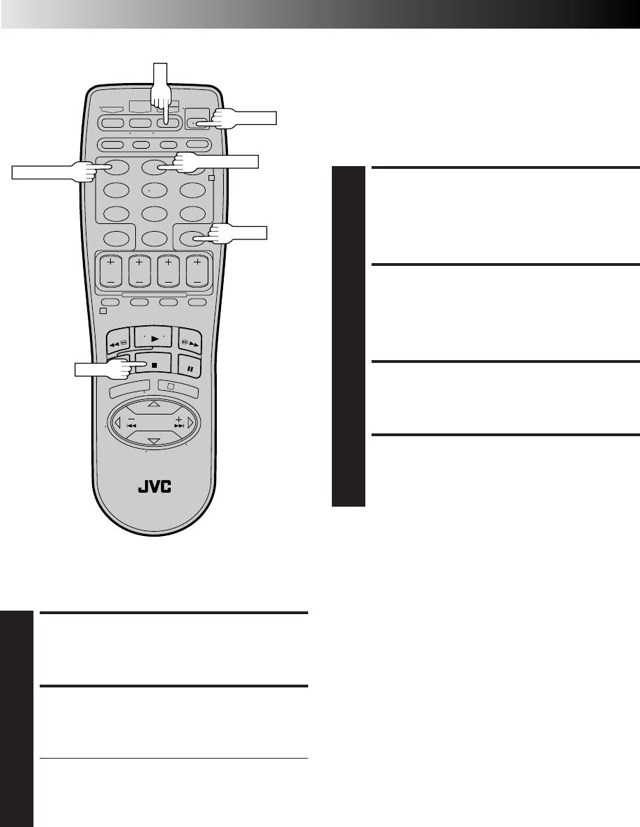
54 EN
123
456
789
0
2
4
1
3
UNPLUG VCR'S POWER
CORD
1
Unplug from the AC outlet.
SET REMOTE CONTROL
CODE
2
While holding down A/B on the remote control, press
the NUMBER key "2" and then press STOP.
PLUG IN POWER CORD
3
Plug back in to the AC outlet.
TURN VCR POWER ON
4
Press POWER on the remote.
The VCR will now respond only to B-code commands.
To set the VCR back to respond to A code signals, repeat the
same procedure as shown above except pressing NUMBER key
"1" instead of "2" in step 2.
You can control two VCRs with the same remote control by
switching the remote's code between A and B (Z Step 2),
pressing "1" for A-code commands and "2" for B-code
commands.
Control Two JVC VCRs
The remote control is capable of controlling two JVC VCRs
independently; one set to respond to your remote control's A
code control signals and another set to respond to B code
control signals. The remote control is preset to send A code
signals because your VCR is initially set to respond to A code
signals. You can easily modify your VCR to respond to B code
signals.
A/B
POWER
NUMBER "1"
STOP
TURN VCR POWER ON
1
Press POWER.
ENGAGE CHILD LOCK
2
Press and hold POWER on the remote control until the
Child Lock indicator ("—") appears on the front display
panel.
●Power turns OFF and the VCR cannot be turned on
from the POWER button on the front panel.
●To cancel Child Lock, press and hold POWER on the
remote until the VCR turns on. During timer record-
ing, pressing TIMER also cancels Child Lock.
NOTES:
●
When Child Lock is engaged, make sure to keep the remote
control out of the reach of children.
●
Timer recording of programs that were previously set can be
performed while the Child Lock is engaged. The feature
remains in effect after the recording is finished.
Child Lock
This feature allows you to prevent the operation of the VCR.
NUMBER "2"
TIMER
SPECIAL FEATURES (cont.)

EN 55
TROUBLESHOOTING
Before requesting service for a problem, use this chart and see if you can repair the trouble yourself. Small problems are often easily
corrected, and this can save you the trouble of sending your VCR off for repair.
POSSIBLE CAUSE
●The power cord is disconnected.
●The TIMER mode is engaged with
Auto Timer set to "OFF" (Z pg. 45).
●The Child Lock mode is engaged.
●The batteries are discharged.
SYMPTOM
1. The power won’t come on.
2. The clock works, but the VCR’s
power won’t come on.
3. The remote control won’t function.
CORRECTIVE ACTION
Connect the power cord.
Press TIMER to disengage.
Press and hold POWER on the remote
to disengage the mode (Z pg. 54).
Replace the dead batteries with new
ones.
SYMPTOM
1. The cassette gets stuck partway
during loading, and is ejected.
CORRECTIVE ACTION
Make sure the cassette's window is
facing up, the rear label side is facing
you and the arrow on the front of the
cassette is pointing towards the VCR.
Then insert the cassette.
POSSIBLE CAUSE
●The cassette was inserted incorrectly.
SYMPTOM
1. The tape is running but the picture
won’t appear.
2. Noise appears during visual search.
3. Breaks are noticeable in Hi-Fi
soundtrack.
4. The playback picture is blurred or
interrupted, even though TV
broadcasts are clear.
5. The Hi-Fi soundtrack cannot be
heard.
POSSIBLE CAUSE
●If you’re using the RF OUT connec-
tion (Z pg. 6), the channel selector
on the TV is set incorrectly.
●If you’re using the AV connection
(Z pg. 6), the TV receiver is set to
the wrong mode.
●This is normal.
●Automatic tracking is engaged.
●The video heads may be dirty.
●The AUDIO MONITOR option was
set incorrectly.
CORRECTIVE ACTION
Set the channel selector to channel 3
or 4.
Set the TV receiver to its AV mode.
Disengage Auto Tracking and adjust
the tracking manually (Z pg. 25).
The heads must be cleaned. Consult
your JVC dealer.
Set AUDIO MONITOR to "HI-FI"
(Z pg. 29).
CORRECTIVE ACTION
Insert a cassette.
Remove the cassette and cover the
hole with adhesive tape, or load a
cassette on which the record safety
tab is intact.
Set the VCR to the appropriate
channel.
Refer to the directions and the
illustration under “Edit To Or From
Another VCR” (Z pg. 48) or “Edit
From A Camcorder” (Z pg. 49) and
properly connect the units.
Make sure the power to all units is on.
Select the recorder’s appropriate
input mode.
POSSIBLE CAUSE
●There’s no cassette loaded.
●The loaded cassette has had its
record safety tab removed.
●The VCR has been set to its AUX
mode by mistake.
●The VCRs or the camcorder and the
VCR have been incorrectly con-
nected.
●The power to one or more of the
units has not been turned on.
●The recorder’s input mode has been
set incorrectly.
SYMPTOM
1. Recording won’t start.
2. TV broadcasts won’t record
properly.
3. Tape-to-tape editing won’t work.
POWER
TAPE TRANSPORT
PLAYBACK
RECORDING
CONTINUED ON NEXT PAGE

56 EN
TROUBLESHOOTING (cont.)
CORRECTIVE ACTION
Set the clock and/or timer correctly.
Press TIMER and check to make sure
that ‰ appears on the front display
panel.
Re-perform the set-up procedures.
Make sure you have compensated for
Guide Channel and VCR or cable
box channel number mismatches
(Z pg. 40).
Timer programming can’t be performed
when timer recording is in progress.
Wait until it finishes.
Load a cassette with the record safety
tab intact, or with the hole covered
with adhesive tape.
Remove the cassette and cover its
hole with adhesive tape, or replace it
with a cassette on which the safety
tab is intact.
Check the programmed data and re-
program as necessary, then press
TIMER again.
The program may not have been
recorded in its entirety. Next time
make sure you have enough time on
the tape to record the entire program.
Connect the Controller correctly
(Z pg. 16).
After confirming your cable box’s
output channel number, re-access the
Cable Box Set screen and select the
correct number (Z pg. 17).
Make sure the power is on before
timer recording starts.
Connect the Controller correctly
(Z pg. 19).
After confirming your DBS receiver’s
output channel number, re-access the
DBS Receiver Set screen and select
the correct number (Z pg. 20).
Set the correct DBS Receiver brand
code (Z pg. 21).
Make sure the power is on before
timer recording starts.
Set "CABLE BOX SET" to "OFF"
(Z pg. 17).
Re-perform the VCR Plus+ setup
procedure (Z pg. 40).
Wait until a space in memory clears,
or cancel unnecessary program
information (Z pg. 44).
SYMPTOM
1. Timer recording won’t work.
2. Timer programming won’t work.
3. ‰ and ] on the front display
panel won’t stop blinking.
4. The cassette is automatically
ejected, and ‰ and ] on the
front display panel won’t stop
blinking.
5. ‰ blinks for 10 seconds and the
timer mode is disengaged.
6. The cassette is automatically
ejected, the power shuts off and ‰
and ] won’t stop blinking.
7. Cable channels are not automatically
switched during timer recording.
8. Satellite channels are not automati-
cally switched during timer
recording.
9. Timer recording begins as sched-
uled, but the channel is always
incorrect.
10.We moved, and now VCR Plus+
doesn’t work properly.
11.“PROGRAM FULL” is displayed on
the screen.
POSSIBLE CAUSE
●The clock and/or the timer have
been set incorrectly.
●The timer is not engaged.
●The VCR has not been set up properly.
●Timer recording is in progress.
●The timer is engaged but there’s no
cassette loaded.
●The loaded cassette has had its
record safety tab removed.
●TIMER has been pressed when there
are no programs in memory, or the
timer record program information
has not been programmed correctly.
●The end of tape was reached during
timer recording.
●The Controller is not properly
connected to the VCR.
●The output channel selected in the
Cable Box Set screen is incorrect.
●The cable box’s power is off.
●The Controller is not properly
connected to the VCR.
●The output channel selected in the
DBS Receiver Set screen is incorrect.
●The VCR is not set correctly to
control the DBS Receiver
●The DBS receiver’s power is off.
●Even though you don't use an
external Cable Box, "CABLE BOX
SET" is set to "ON".
●The receivable stations in the new area
are received on different channels than
those in the previous area.
●All 8 programs of the VCR’s timer
memory are used.
TIMER RECORDING
EN 57
OTHER PROBLEMS
CORRECTIVE ACTION
If you need the skipped channels,
restore them (Z pg. 15).
Press PAUSE to pause the recording,
change channels, then press PLAY to
resume recording.
Re-set the remote control to the
correct brand (Z pg. 51 or 52 or 53).
Select a different Host Channel during
the Semi-Auto setting procedure
(Z pg. 12), or perform the Manual
setting procedure (Z pg. 13).
SYMPTOM
1. When scanning channels, some of
them are skipped over.
2. The channel can’t be changed.
3. The remote control won’t operate
my TV or cable box or DBS receiver.
4. Even though Auto or Semi-Auto
clock setting has been selected, the
clock is incorrect.
POSSIBLE CAUSE
●Those channels have been preset to
be skipped.
●Recording is in progress.
●The remote control brand setting is
incorrect.
●The clock setting data received from
the Host Channel is incorrect.
ATTENTION
This VCR contains microcomputers. External electronic noise or interference can cause microcomputer to malfunction. If the VCR
does not operate correctly switch its power off and unplug the power cord from the AC supply. Wait for a while and then plug the
power back in. Eject and check the condition of the cassette. If everything appears normal resume operating the VCR as usual.

58 EN
QUESTIONS AND ANSWERS
PLAYBACK
Q. What happens if the end of the tape is reached
during playback or search?
A. The tape is automatically rewound to the beginning.
Q. Can the VCR indefinitely remain in the still mode?
A. No. It stops automatically after 5 minutes to protect
the heads.
Q. During search, slow, still and frame-by-frame
playback, I can’t hear any audio. What’s the
problem?
A. This is normal.
Q. During search, still and frame-by-frame playback,
the picture is intermittent. What’s the cause?
A. Picture loss occurs when these types of playback are
attempted with a tape recorded in LP mode. Pressing
PLAY to return to normal playback will restore the
picture.
Q. When returning from multi-speed search to normal
playback, the picture is disturbed. Should I be
concerned about this?
A. No, it is normal.
Q. Noise bars appear during multi-speed search. What’s
the problem?
A. This is normal.
Q. When playing back programs that have been timer-
recorded with consecutive times (such one program
from 8:00 to 9:00 and another one from 9:00 to
10:00), the picture and sound become momentarily
distorted at the point where the first program ends
and the second program begins. Is this a
malfunction?
A. No. This is normal.
Q. Other than preventing further recording, what effect
does removing the safety tab have?
A. It disables marking of index codes.
Q. Sometimes, during Index Search, the VCR can’t find
the program I want to see. Why not?
A. There may be index codes too close together.
Q. During playback, on-screen operational indicators
sometimes jitter. Why does this happen?
A. If the condition of the tape being played back is not
good, jittering of the video (including on-screen
indicators) may occur.
RECORDING
Q. When I pause and then resume a recording, the end
of the recording before the pause is overlapped by
the new recording. Why does this happen?
A. This is normal. It reduces distortion at the pause and
resume points.
Q. Can the VCR indefinitely remain in the Record-Pause
mode?
A. No. The VCR automatically goes to its Stop mode
after 5 minutes to protect the heads. When paused
during Instant Timer Recording (ITR), the VCR shuts
off automatically after 5 minutes.
Q. What happens if the tape runs out during recording?
A. The VCR automatically rewinds it to the beginning.
TIMER RECORDING
Q. REC and ‰ remain lit on the front display panel. Is
there a problem?
A. No. This is a normal condition for a timer recording
in progress.
Q. Can I program the timer while I’m watching a tape
or a TV broadcast?
A. Yes, but while you are setting the timer you won't see
the tape's or broadcast program's picture as it is
replaced by the on-screen menu. The audio from the
tape or broadcast program will be present during the
setting of the timer.

EN 59
INDEX
List Of Terms
This guide serves as a quick way to locate frequently used terms and on-screen display names.
A
A/B Code ....................................................................54
Active Video Calibration .............................................32
Add Channel ...............................................................15
Audio Monitor ............................................................29
Auto Channel Setting ..................................................14
Auto Daylight Saving Time ..........................................12
Auto SP→EP Timer ......................................................45
Auto Timer ..................................................................45
Automatic Tracking .....................................................25
Aux Input ....................................................................48
AV Compu Link Playback ...........................................31
AV Connection .............................................................6
B
Band ...........................................................................14
C
Cable Box ...................................................................16
Cable Box Brand Setting..............................................18
Cable Box Controller...................................................16
Cancel Program ..........................................................44
Cassette Adapter.................................... ......................22
Check Program ...........................................................44
Child Lock ..................................................................54
Connection to TV ..........................................................6
Contents........................................................................5
Counter Reset..............................................................27
D
DBS Receiver ..............................................................19
DBS Receiver Brand Setting ........................................21
DBS Receiver Controller .............................................19
Delete Channel ...........................................................15
E
Editing.........................................................................48
Express Timer Programming ........................................42
Express Timer Recording .............................................42
F
Frame-by-Frame Playback ...........................................24
G
Guide Channel Setting ................................................41
H
Host Channel Selection ...............................................12
I
Index Search ...............................................................25
Insert Cassette .............................................................22
Instant ReView ............................................................27
ITR (Instant Timer Recording) ......................................46
L
Language Selection .....................................................10
M
Main Menu .................................................................10
Manual Channel Setting ..............................................15
Manual Clock Setting ..................................................13
Manual Tracking .........................................................25
MBR (Multi-Brand Remote) Code Setting.....................51
Movie Advance ...........................................................30
N
Next-Function Memory ...............................................27
O
On-Screen Display ......................................................28
P
PBS Channel .................................................................8
Playback .....................................................................22
Plug & Play ...................................................................8
R
REC LINK ....................................................................47
Record Safety Tab .......................................................23
Recording ...................................................................23
Repeat Playback..........................................................27
Reverse Motion Playback ............................................24
Reverse Slow Motion Playback ...................................24
RF Connection ..............................................................6
S
SAP (Second Audio Program) ......................................37
Second Audio .............................................................37
Select Cable Box Output Channel ...............................17
Select DBS Receiver Output Channel ..........................20
Semi-Auto Clock Setting..............................................12
Skip Search .................................................................25
Slow Motion Playback ................................................24
Specifications ..............................................................63
Still Picture Playback...................................................24
Superimpose ...............................................................28
S-VHS (Super VHS) .....................................................35
S-VHS ET ....................................................................36
S-Video Connection ......................................................7
T
Tape Position Indicator ................................................27
Tape Speed Setting ......................................................23
Time Zone Selection ...................................................13
Tuner Setting ...............................................................14
V
Variable-Speed Search ................................................25
VCR Plus+ Timer Programming ...................................38
VCR Plus+ Timer Recording ........................................38
Video Stabilizer ...........................................................26
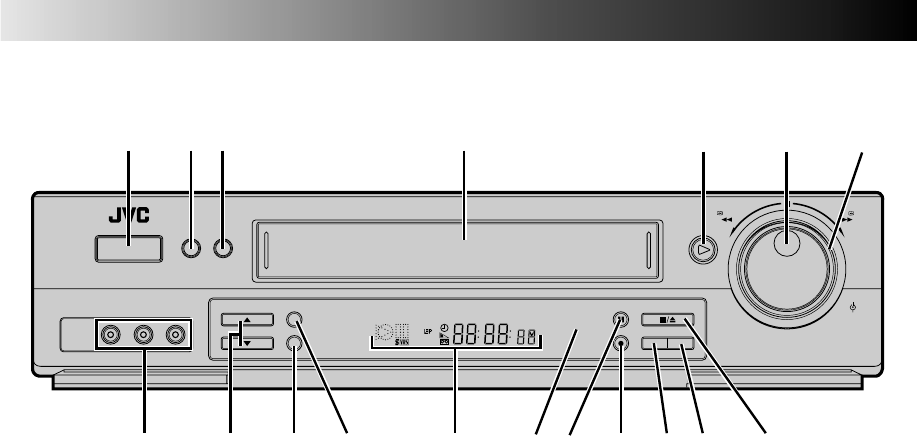
60 EN
INDEX (cont.)
FRONT VIEW
1Power On/Off Button (Z pg. 10)
2MENU Button (Z pg. 10)
3OK Button (Z pg. 10)
4Cassette Loading Slot
5PLAY Button (Z pg. 22)
6JOG Dial (Z pg. 24)
7SHUTTLE Ring (Z pg. 22)
8VIDEO/AUDIO Input Connectors (Z pg. 49)
9Channel [CH] 5∞ Button (Z pg. 23)
0REC LINK Button (Z pg. 47)
!S-VHS ET Button (Z pg. 36)
@Front Display Panel (Z pg. 61)
#Remote Control Sensor
$PAUSE Button (Z pg. 24)
%Record [REC] Button (Z pg. 23)
^SP/EP Button (Z pg. 23)
&TV/VCR Button (Z pg. 34)
* STOP/EJECT Button (Z pg. 22)
REW
SP/EP
PAUSE
REC
STOP/EJECT
PLAY
TV/VCR
FF
JOG
SHUTTLE
MENU OK
POWER
VIDEO
(MONO)
L –AUDIO– R
REC LINK
S-VHS ET
CH
SP VCR
1 2 3
*
&% ^@09 !
45 6 7
8 # $
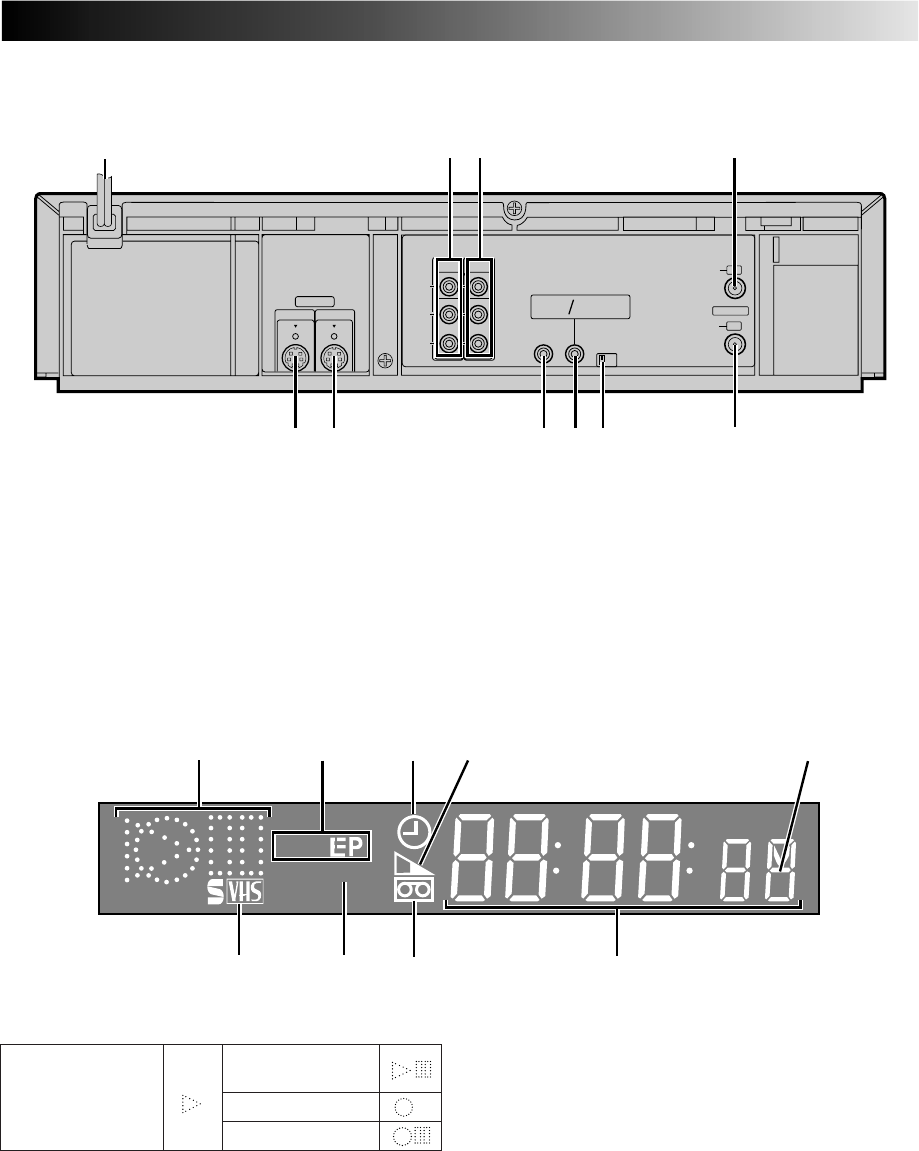
EN 61
REAR VIEW
FRONT DISPLAY PANEL
SP VCR
76 89
12 3 4
5
ANTENNA IN
VIDEO
AUDIO
VHF/UHF
L
(MONO)
R
OUT
TV
OUT IN
CH4
CH3
REMOTE
PAUSE AV
COMPULINK
CABLE
BOX
OUT
S VIDEO
IN
1
0
9
2 3 4
75 6 8
1Power Cord (Z pg. 6)
2VIDEO/AUDIO Output Connectors (Z pg. 48)
3VIDEO/AUDIO Input Connectors (Z pg. 48)
4ANTENNA IN Connector (Z pg. 6)
5S-Video (S-VHS) Output Connector (Z pg. 48)
6S-Video (S-VHS) Input Connector (Z pg. 48)
7CABLE BOX Controller Connector (Z pg. 16, 19)
8REMOTE PAUSE/AV COMPULINK Connector
●REMOTE PAUSE Connector (Z pg. 49)
●AV COMPU-LINK Connector (Z pg. 31)
9Channel 3/4 Switch (Z pg. 6)
0TV OUT Connector (Z pg. 6)
2Tape Speed Indicators (Z pg. 23)
3Timer Mode Indicator
4Tape Remaining Time Indicator (Z pg. 36)
5Child Lock Indicator (Z pg. 54)
6S-VHS Indicator (Z pg. 35)
7VCR Mode Indicator (Z pg. 36)
8“Cassette Loaded” Mark
9Channel Display [“L-1” and "F-1" for AUX mode]
Counter Display (Z pg. 8)
Clock Display (Z pg. 8)
1Symbolic Mode Indicators
STILL:
SLOW:
RECORD:
RECORD PAUSE:
PLAY:
FF/REW VARIABLE
SEARCH:
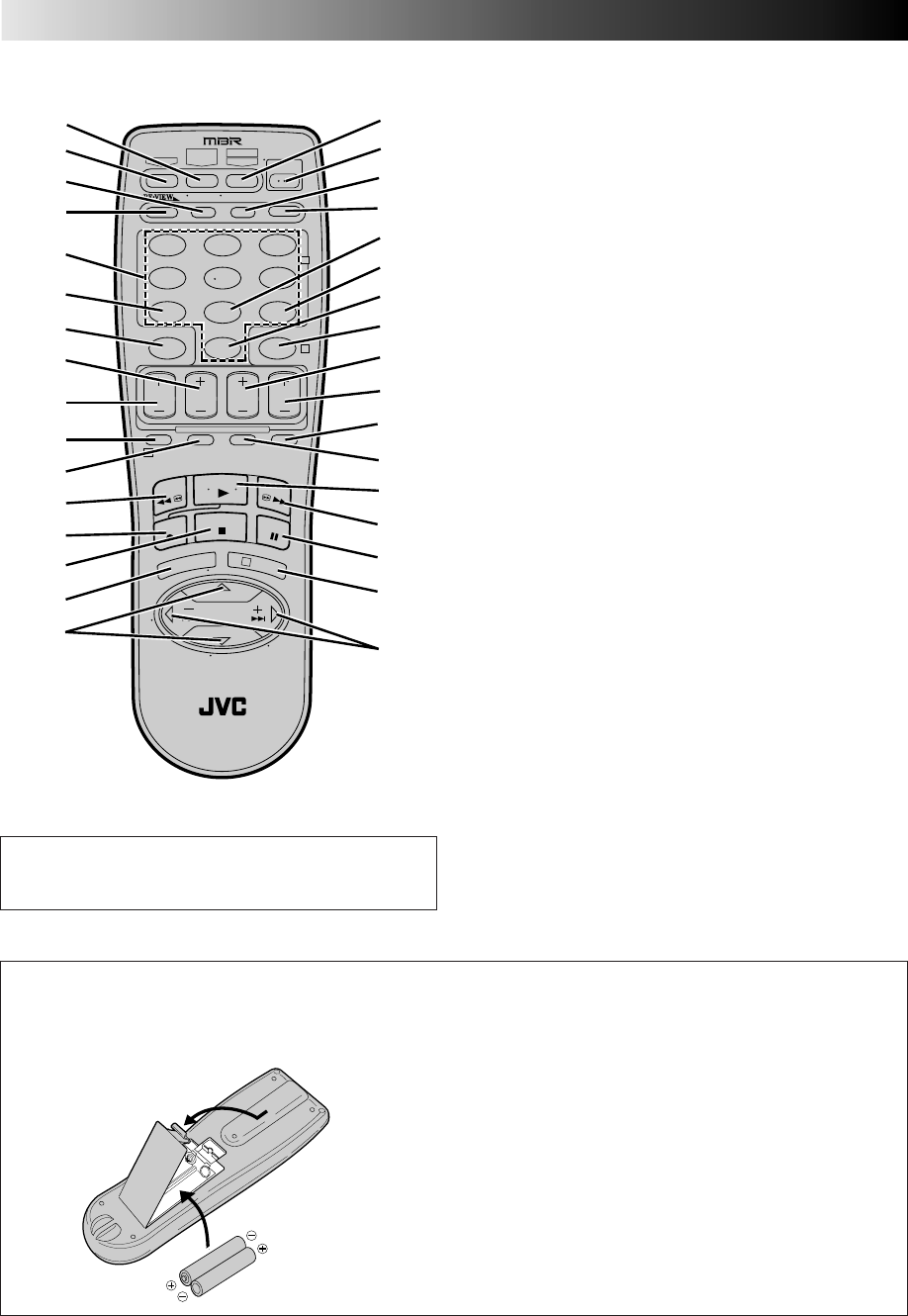
62 EN
REMOTE CONTROL 1CABLE/DBS Button (Z pg. 52, 53)
2TV Button (Z pg. 51)
3TV/VCR Button (Z pg. 34)
4Instant REVIEW Button (Z pg. 27)
5NUMBER Buttons (Z pg. 23, 38)
6DBS Button (Z pg. 43)
7CANCEL Button (Z pg. 44)
Counter [C.] RESET Button (Z pg. 27)
8STOP +/– Button (Z pg. 42)
9START +/– Button (Z pg. 42)
0PROG. Button (Z pg. 38, 42)
!PROG. CHECK Button (Z pg. 44)
@Rewind [REW] Button (Z pg. 22)
#Record [REC] Button (Z pg. 23)
$STOP Button (Z pg. 22)
%MENU Button (Z pg. 10)
^SHUTTLE PLUS %fi Button (Z pg. 10)
TV Channel [CH] +/– Button (Z pg. 51, 52, 53)
&MBR SET Button (Z pg. 51, 52, 53)
A/B Code Button (Z pg. 54)
*POWER On/Off Button (Z pg. 10)
(ENTER Button (Z pg. 23)
On-Screen Display [OSD] Button (Z pg. 28)
)DISPLAY Button (Z pg. 27)
qDAILY Timer Recording Button (Z pg. 39, 43)
wWEEKLY Timer Recording Button (Z pg. 39, 43)
e"AUX" Mode Select Button (Z pg. 48)
rTIMER Button (Z pg. 39, 43)
tDATE +/– Button (Z pg. 42)
yChannel [CH] +/– Button (Z pg. 23, 43)
uSKIP SEARCH Button (Z pg. 25, 30)
iRecording Speed [SP/EP] Button (Z pg. 23)
oPLAY Button (Z pg. 22)
pFast-Foward [FF] Button (Z pg. 22)
QPAUSE Button (Z pg. 24)
WOK Button (Z pg. 10)
ESHUTTLE PLUS ™£ ( ) Button
(Z pg. 24, 25)
TV Volume [VOL.] +/– Button (Z pg. 51)
Installing Batteries
1Open the battery compartment cover.
2Insert 2 "AA"-size batteries (provided) in the direction
indicated under the battery cover.
3Replace the cover.
How To Use
The remote control can operate most of your VCR's func-
tions.
1Point the remote control toward the sensor window.
(Z pg.60)
2Press the appropriate operation button.
3The maximum operating distance of the remote control is
about 8 m.
NOTES:
●
This remote control can also operate various brands of TVs,
Cable Boxes and DBS Receivers. For instructions,
Z
pg. 51 – 53.
●
If the remote control doesn't work properly, remove its
batteries, wait a short time, replace the batteries and then
try again.
%
fi
T
V
C
H
+
T
V
V
O
L
–
T
V
C
H
–
T
V
V
O
L
+
TV
CANCEL
TIMER
START STOP DATE
PLAY
REW
REC
STOP
SHUTTLE
PLUS
PAUSE
FF
MENU
OK
CH
POWER
TV/VCR
C. RESET
DBS DAILY(M-F)
AUX
WEEKLY
PROG
CHECK
PROG SP/EP SKIP SEARCH
DISPLAY
ENTER/OSD
CABLE/
DBS
123
456
789
0
2
4
1
3
EXPRESS PROGRAMMING
MULTI BRAND
REMOTE CONTROL UNIT
MBRSET
A/B
i
o
u
)
W
1
3
8
7
6
2
9
4
0
5
!
@
#
$
%
&
*
(
r
e
w
q
t
y
Q
p
^E
Buttons with a small dot on the left side of the name can
also be used to operate your TV while holding down the TV
button. Z pg. 51
INDEX (cont.)

EN 63
GENERAL
Power requirement : AC 120 V` , 60 Hz
Power consumption
Power on : 28 W
Power off : 3 W
Temperature
Operating : 5°C to 40°C (41°F to 104°F)
Storage : –20°C to 60°C (–4°F to140°F)
Operating position : Horizontal only
Dimensions (W x H x D) : 401 x 94 x 340 mm
(15-13/16" x 3-3/4" x 13-7/16")
Weight : 3.8 kg (8.4 lbs)
Format : S-VHS/VHS NTSC standard
Maximum recording time
SP : 210 min. with ST-210 video
cassette
EP : 630 min. with ST-210 video
cassette
VIDEO/AUDIO
Signal system : NTSC-type color signal and
EIA monochrome signal, 525
lines/60 fields
Recording/
Playback system : DA-4 (Double Azimuth) head
helical scan system
Signal-to-noise ratio : 45 dB
Horizontal resolution : 240 lines (VHS)
: 400 lines (S-VHS)
Frequency range
Normal audio : 70 Hz to 10,000 Hz
Hi-Fi audio : 20 Hz to 20,000 Hz
Input/Output : RCA connectors
(IN x 2, OUT x 1)
: S-Video connectors
(IN x 1, OUT x 1)
TUNER
Tuning system : Frequency-synthesized tuner
Channel coverage
VHF : Channels 2–13
UHF : Channels 14–69
CATV : 113 Channels
RF output : Channel 3 or 4 (switchable;
preset to Channel 3 when
shipped) 75 ohms,
unbalanced
SPECIFICATIONS
TIMER
Clock reference : Quartz
Program capacity : 1-year programmable timer/
8 programs
Memory backup time : Approx. 10 min.
ACCESSORIES
Provided accessories : RF cable (F-type),
Infrared remote control unit,
“AA” battery x 2,
Audio/Video Cable,
S-Video cable (4-pin),
Controller
Specifications shown are for SP mode unless otherwise specified.
E. & O.E. Design and specifications subject to change without
notice.

64 EN
HOW TO LOCATE YOUR JVC SERVICE CENTER
TOLL FREE: 1-800-252-5722
JVC SERVICE & ENGINEERING
COMPANY OF AMERICA
DIVISION OF US JVC CORP.
FACTORY SERVICE CENTER LOCATIONS
If you ship the product...
ACCESSORIES
107 Little Falls Road 1500 Lakes Parkway 705 Enterprise Street
Fairfield, NJ 07004-2105 Lawrenceville, GA 30243-5857 Aurora, IL 60504-8135
(973) 808-9279 (770) 339-2522 (630) 851-7855
5665 Corporate Avenue 10700 Hammerly Boulevard, Suite 110 2969 Mapunapuna Place, Suite 101
Cypress, CA 90630-4727 Houston, TX 77043-2310 Honolulu, HI 96819-2000
(714) 229-8011 (713) 935-9331 (808) 833-5828
230 Eliot Street 8192 W State Road 84 890 Dubuque Avenue
Ashland, MA 01721-2377 Davie, FL 33324-4611 South San Francisco, CA 94080-1804
(508) 881-5923 (954) 472-1960 (415) 871-2666
Sophisticated electronic products may require occasional service. Just as quality is a keyword in the engineering and production
of the wide array of JVC products, service is the key to maintaining the high level performance for which JVC is world famous. The
JVC service and engineering organization stands behind our products.
NATIONAL HEADQUARTERS
JVC SERVICE & ENGINEERING COMPANY OF AMERICA
DIVISION OF US JVC CORP.
107 Little Falls Road
Fairfield, NJ 07004-2105
Pack your JVC unit in the original carton or one of equivalent
size and strength. Enclose, with the unit, a letter stating the
problem or symptom that exists and also a copy of the receipt
or bill of sale you received when you purchased your JVC
unit. Print your home return address on the outside and the
inside of the carton. Send to the appropriate JVC Factory
Service Center as listed above.
To purchase accessories for your JVC product, you may
contact your local JVC Dealer.
Or from the 48 Continental United States call toll free:
1-800-882-2345.
Dear customer:
In order to receive the most satisfaction from your purchase, read the instruction booklet before operating the unit. In the event
that repair is necessary, or for the address nearest your location, please refer to the factory service center list below or within the
Continental United States, call 1-800-252-5722 for your authorized servicer. Remember to retain your Bill of Sale for Warranty
Service.
— JVC
CAUTION
To prevent electrical shock, do not open the cabinet. No user
serviceable parts inside.
Refer servicing to qualified service personnel.
Don't service it yourself.
FOR SERVICING (Only in U.S.A.)

EN 65
LIMITED WARRANTY CONSUMER VIDEO 1-90
JVC COMPANY OF AMERICA warrants this product and all parts thereof, except as set forth below ONLY TO THE ORIGINAL
PURCHASER AT RETAIL to be FREE FROM DEFECTIVE MATERIALS AND WORKMANSHIP from the date of original retail
purchase for the period as shown below. ("The Warranty Period")
THIS LIMITED WARRANTY IS VALID ONLY IN THE FIFTY (50) UNITED STATES, THE DISTRICT OF COLUMBIA AND IN
COMMONWEALTH OF PUERTO RICO.
WHAT WE WILL DO:
If this product is found to be defective, JVC will repair or replace defective parts at no charge to the original owner. Such repair
and replacement services shall be rendered by JVC during normal business hours at JVC authorized service centers. Parts
used for replacement are warranted only for the remainder of the Warranty Period. All products and parts thereof may be
brought to a JVC authorized service center on a carry-in basis except for Television sets having a screen size 25 inches and
above which are covered on an in-home basis.
WHAT YOU MUST DO FOR WARRANTY SERVICE:
Return your product to a JVC authorized service center with a copy of your bill of sale. For your nearest JVC authorized
service center, please call toll free: (800) 252-5722.
If service is not available locally, box the product carefully, preferably in the original carton, and ship, insured, with a copy of
your bill of sale plus a letter of explanation of the problem to the nearest JVC Factory Service Center, the name and location
of which will be given to you by the toll-free number.
If you have any questions concerning your JVC Product, please contact our Customer Relations Department.
WHAT IS NOT COVERED:
This limited warranty provided by JVC does not cover:
1. Products which have been subject to abuse, accident, alteration, modification, tampering, negligence, misuse, faulty
installation, lack of reasonable care, or if repaired or serviced by anyone other than a service facility authorized by JVC to
render such service, or if affixed to any attachment not provided with the products, or if the model or serial number has been
altered, tampered with, defaced or removed;
2. Initial installation and installation and removal for repair;
3. Operational adjustments covered in the Owner's Manual, normal maintenance, video and audio head cleaning;
4. Damage that occurs in shipment, due to act of God, and cosmetic damage;
5. Signal reception problems and failures due to line power surge;
6. Video Pick-up Tubes/CCD Image Sensor, Cartridge, Stylus (Needle) are covered for 90 days from the date of purchase;
7. Accessories;
8. Batteries (except that Rechargeable Batteries are covered for 90 days from the date of purchase); from the date of purchase);
There are no other express warranties except as listed above.
THE DURATION OF ANY IMPLIED WARRANTIES INCLUDING THE IMPLIED WARRANTY OF MERCHANTABILITY, IS
LIMITED TO THE DURATION OF THE EXPRESS WARRANTY HEREIN.
JVC SHALL NOT BE LIABLE FOR THE LOSS OF USE OF THE PRODUCT, INCONVENIENCE, LOSS OR ANY OTHER
DAMAGES, WHETHER DIRECT, INCIDENTAL OR CONSEQUENTIAL (INCLUDING, WITHOUT LIMITATION, DAMAGE TO
TAPES, RECORDS OR DISCS) RESULTING FROM THE USE OF THIS PRODUCT, OR ARISING OUT OF ANY BREACH
OF THIS WARRANTY. ALL EXPRESS AND IMPLIED WARRANTIES, INCLUDING THE WARRANTIES OF
MERCHANTABILITY AND FITNESS FOR PARTICULAR PURPOSE, ARE LIMITED TO THE WARRANTY PERIOD SET
FORTH ABOVE.
Some states do not allow the exclusion of incidental or consequential dameges or limitations on how long an implied warranty
lasts, so these limitations or exclusions may not apply to you. This warranty gives you specific legal rights and you may also
have other rights which vary from state to state.
JVC COMPANY OF AMERICA 41 Slater Drive
DIVISION OF US JVC CORP. Elmwood Park, New Jersey 07407
REFURBISHED PRODUCTS CARRY A SEPARATE WARRANTY, THIS WARRANTY DOES NOT APPLY. FOR DETAILS OF
REFURBISHED PRODUCT WARRANTY, PLEASE REFER TO THE REFURBISHED PRODUCT WARRANTY INFORMATION
PACKAGED WITH EACH REFURBISHED PRODUCT.
For customer use:
Enter below the Model No. and Serial No. which is located either on the rear, bottom or side of the cabinet. Retain this information for future
reference.
Model No.: Serial No.:
Purchase date: Name of dealer:
PARTS LABOR
1 YR 90 DAYS
WARRANTY (Only in U.S.A.)

MEMO

MEMO

HR-S3500U
COPYRIGHT © 1998 VICTOR COMPANY OF JAPAN, LTD. U/U(C) Printed in Malaysia
0598 IYV
*
UN
*
PJ
JVC COMPANY OF AMERICA
DIVISION OF US JVC CORP.
41 Slater Drive, Elmwood Park, N.J. 07407
JVC CANADA INC.
21 Finchdene Square, Scarborough Ontario M1X 1A7
