JVC KD AVX55A AVX77/KD AVX55 User Manual AVX55A, AVX77A LVT1938 012A
KD-AVX77A KD-AVX77A LVT1938-012A English, INSTALLATION
KS-HP2 LVT1938-012A
User Manual: JVC KD-AVX55A KD-AVX55A, KD-AVX77A English, INSTALLATION
Open the PDF directly: View PDF ![]() .
.
Page Count: 4
1
KD-AVX77/KD-AVX55
Installation/Connection Manual
This unit is designed to operate on 12 V DC, NEGATIVE ground electrical systems. If your vehicle does not have this system, a
voltage inverter is required, which can be purchased at JVC car audio dealers.
WARNINGS
• DO NOT install any unit or wire any cable in a location where;
– it may obstruct the steering wheel and gearshift lever operations, as this may result in a traffic accident.
– it may obstruct the operation of safety devices such as air bags, as this may result in a fatal accident.
– it may obstruct visibility.
• DO NOT operate any unit while manipulating the steering wheel, as this may result in a traffic accident.
• The driver must not watch the monitor while driving. It may lead to carelessness and cause an accident.
• The driver must not put on the headphones while driving. It is dangerous to shut off the outside sounds while driving.
• If you need to operate the unit while driving, be sure to look around carefully.
• If the parking brake is not engaged, “Parking Brake” appears on the monitor, and no playback picture will be shown.
– This warning appears only when the parking brake lead is connected to the parking brake system built in the car.
Notes on electrical connections:
• Replace the fuse with one of the specified rating. If the fuse blows frequently, consult your JVC car audio dealer.
• It is recommended to connect speakers with a maximum power of more than 50 W (both at the rear and at the front, with an
impedance of 4 to 8 Ω).
If the maximum power is less than 50 W, change <Amplifier Gain> setting to prevent the speakers from being damaged (see page
24 of the INSTRUCTIONS).
• To prevent short circuits, cover the terminals of the UNUSED leads with insulating tape.
• The heat sink becomes very hot after use. Be careful not to touch it when removing this unit.
• The heat sink becomes very hot. Do not place any cable where it may touch the heat sink.
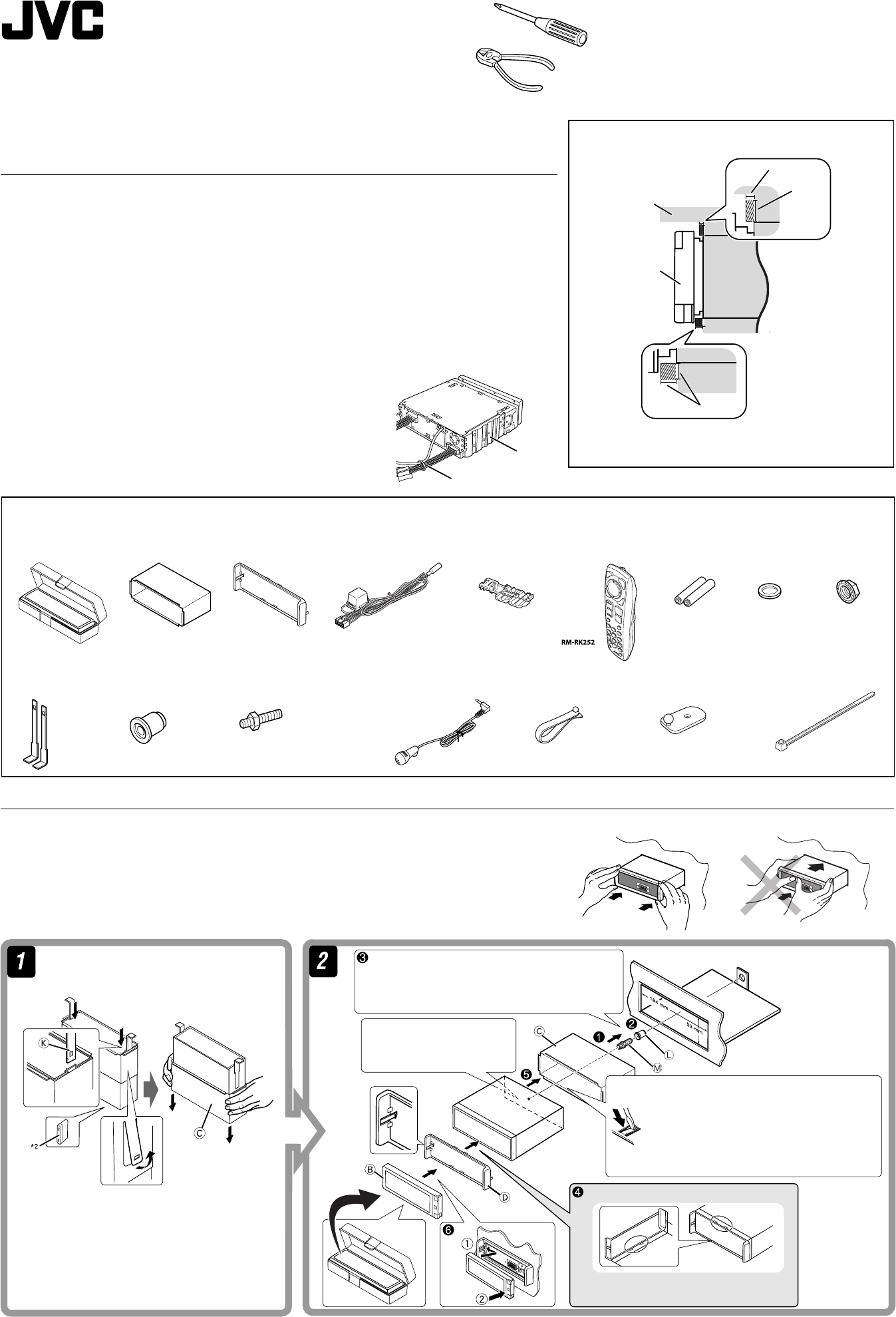
• Gather the cables up using the supplied cable tie as illustrated (only for KD-AVX77).
I
Washer (ø5)
J
Lock nut (M5)
M
Mounting bolt—M5 x 20 mm
L
Rubber cushion
K
Handles
*2 When you stand the unit, be careful not to damage the
fuse on the rear.
Do the required electrical connections.
Bend the appropriate tabs to hold the
sleeve firmly in place.
F
Crimp connector
Do not block the fan.
INSTALLATION (IN-DASH MOUNTING)
The following illustration shows a typical installation. If you have any questions or require information regarding installation kits, consult your JVC car audio dealer or a company supplying kits.
• If you are not sure how to install this unit correctly, have it installed by a qualified technician.
• Make sure not to block the fan on the rear to maintain proper ventilation when installing the unit.
• You cannot install the unit on the car which has any obstacles in the space shown in “Required space for installation” above.
Caution when installing
Fit the unit into the mounting sleeve by using four corners of the trim plate.
• DO NOT press the panel (shaded in the illustration).
Required space for installation
Monitor panel
LVT1938-012A
[A] 0409MNMMDWJEIN
EN
© 2009 Victor Company of Japan, Limited
Parts list for installation and connection
The following parts are provided for this unit. After checking them, please set them correctly.
Dashboard
C
Sleeve
E
Power cord
D
Trim plate
Fit the protrusions outside the unit.
Trim plate is detached on this illustration for explanation.
G
Remote controller
A / B
Hard case/Control panel
3 mm
6 mm
5 mm
Heat sink
Q
Cable tie
H
Batteries
Q
Cable tie*1
O
Microphone clip*1
P
Microphone holder*1
N
Microphone*1
*1 Only for KD-AVX77.
Instal_KDAVX7755[A]f.indb 1Instal_KDAVX7755[A]f.indb 1 09.4.3 11:51:02 AM09.4.3 11:51:02 AM
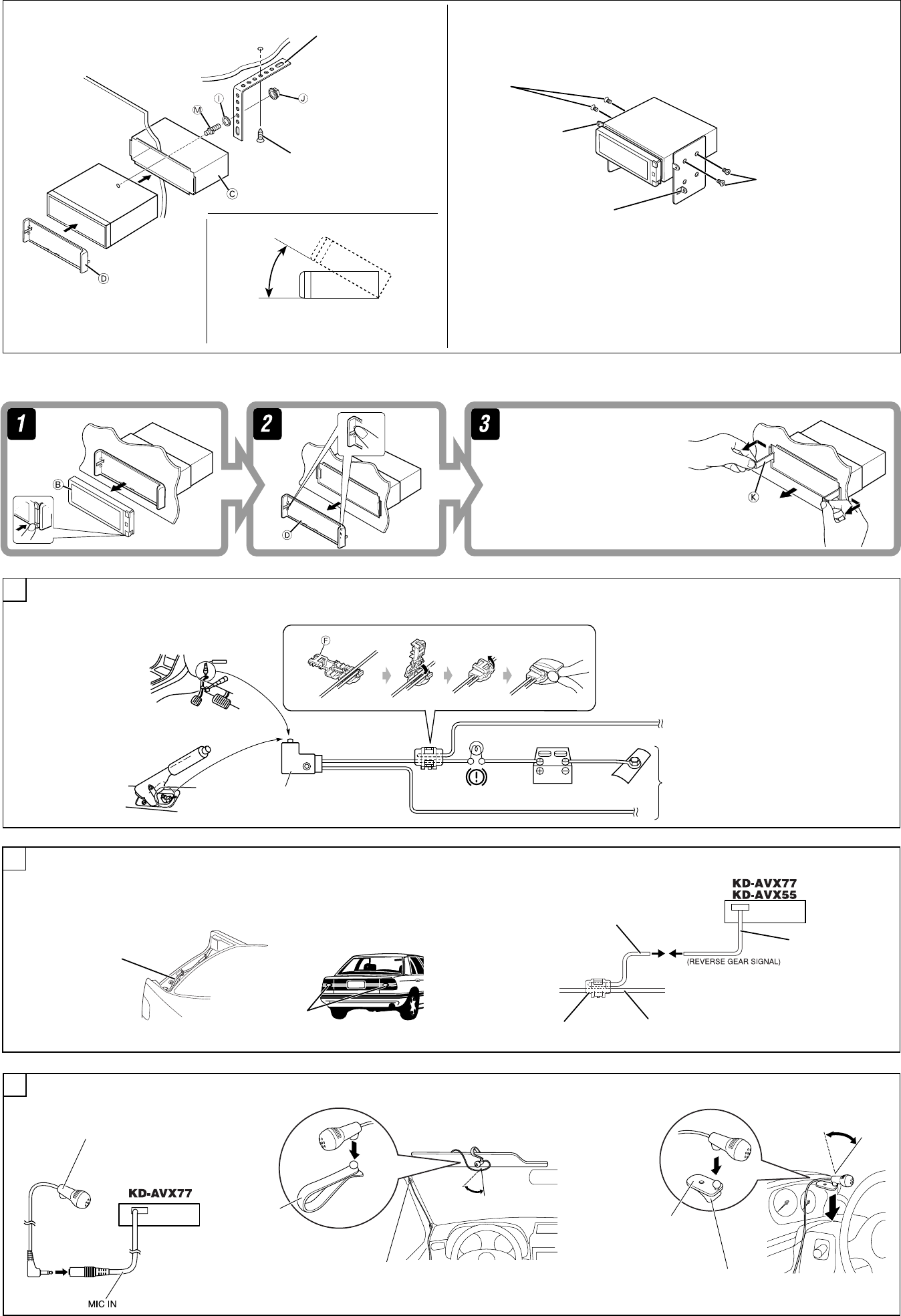
2
When using the optional stay When installing the unit without using the sleeve
In a car having the “Required space for installation” (see page 1), first remove the car radio and install the
unit in its place.
Screw (option)
Stay (option)
Fire wall
Dashboard
Bracket *3
*3 Not included for this unit.
Flat type screws—M5 x 8 mm*3
Bracket *3
Install the unit at an angle of less than 30˚.
Note: • When installing the unit on the mounting bracket, make sure to use the 8 mm-long screws.
If longer screws are used, they could damage the unit.
• Tighten the screws firmly to prevent the unit from falling off.
Removing the unit
Before removing the unit, release the rear section.
Insert the two handles, then pull them as
illustrated so that the unit can be removed.
30˚
Flat type screws—M5 x 8 mm*3
Connect the parking brake lead to the parking brake system built in the car.
Parking brake lead (light green)
To metallic body or chassis of the car
Parking brake switch (inside the car)
Parking brake
Connecting the parking brake lead
A
Connecting the reverse gear signal lead (for rear view camera) (REVERSE GEAR SIGNAL)
Locate the reverse lamp lead in the trunk.
To reverse lamp
Reverse lamp lead
Reverse lamp lead
To car battery
Purple with white stripe
Reverse lamps
Extension lead (not supplied)
Crimp connector
(not supplied)
B
Connecting the microphone (only for KD-AVX77)
Secure the microphone cord using cord cramps
(not supplied) if necessary.
or
O
Microphone clip P
Microphone holder
Adhesive tape
N
Microphone
12
C
Instal_KDAVX7755[A]f.indb 2Instal_KDAVX7755[A]f.indb 2 09.4.3 11:51:08 AM09.4.3 11:51:08 AM
3
If your car is equipped with the steering wheel remote controller, you can operate this unit using the
controller. For connection, an exclusive remote adapter (not supplied) which matches your car is
required. For details, consult the same car audio dealer as where the unit is purchased.
To prevent short circuits, we recommend that you disconnect the battery’s negative terminal and make all
electrical connections before installing the unit.
• Be sure to ground this unit to the car’s chassis again after installation.
• Be sure any cable is not caught on the car’s chassis or under seats.
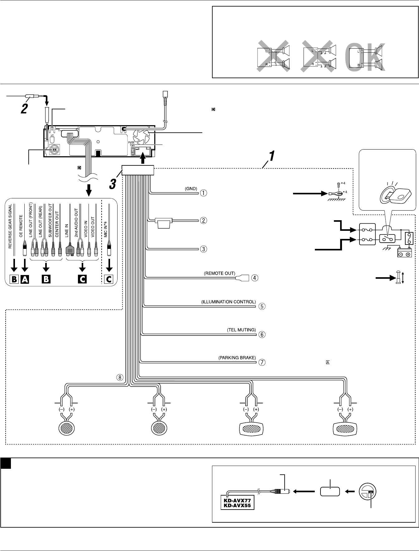
Typical connections
Before connecting: Check the wiring in the vehicle carefully. Incorrect connection may cause serious
damage to this unit.
The leads of the power cord and those of the connector from the car body may be different in color.
1 Connect the colored leads of the power cord in the order specified in the illustration below.
2 Connect the antenna cord.
3 Finally connect the wiring harness to the unit.
15 A fuse
Rear ground terminal
To an external component (see diagram )
To parking brake (see diagram )
Yellow *5
USB cable (see diagram )
To metallic body or chassis of the car
To a live terminal in the fuse block connecting to the car battery
(bypassing the ignition switch) (constant 12 V)
To an accessory terminal in the fuse block Fuse block
Red
To car light control switch
To cellular phone system
To the remote lead of other equipment or power
antenna if any (200 mA max.)
Ignition switch
White with black stripe White Gray with black stripe Gray Green with black stripe Green Purple with black stripe Purple
Left speaker (front) Right speaker (front) Left speaker (rear) Right speaker (rear)
PRECAUTIONS on power supply and speaker connections:
• DO NOT connect the speaker leads of the power cord to the car battery; otherwise, the
unit will be seriously damaged.
• BEFORE connecting the speaker leads of the power cord to the speakers, check the speaker wiring in
your car.
ELECTRICAL CONNECTIONS
Black
Blue with white stripe
Orange with white stripe
Light green
Brown
*4 Not included for this unit
*5• Before checking the operation of this unit prior
to installation, this lead must be connected,
otherwise power cannot be turned on.
• Do not connect the lead directly to the battery.
Fan
Connecting to the steering wheel remote controller
A
OE remote adapter (not supplied)
Steering wheel remote controller
(equipped in the car)
OE REMOTE
Steering wheel remote input
• The fuse blows.
* Are the red and black leads connected correctly?
• Power cannot be turned on.
* Is the yellow lead connected?
• No sound from the speakers.
* Is the speaker output lead short-circuited?
• Sound is distorted.
* Is the speaker output lead grounded?
* Are the “–” terminals of L and R speakers grounded in common?
• Noise interfere with sounds.
* Is the rear ground terminal connected to the car’s chassis using shorter and thicker cords?
• Unit becomes hot.
* Is the speaker output lead grounded?
* Are the “–” terminals of L and R speakers grounded in common?
• This unit does not work at all.
* Have you reset your unit?
TROUBLESHOOTING
*6 Only for KD-AVX77.
Instal_KDAVX7755[A]f.indb 3Instal_KDAVX7755[A]f.indb 3 09.4.3 11:51:11 AM09.4.3 11:51:11 AM
s
4
USB cable—approx.1.2 m
USB 2.0 cable
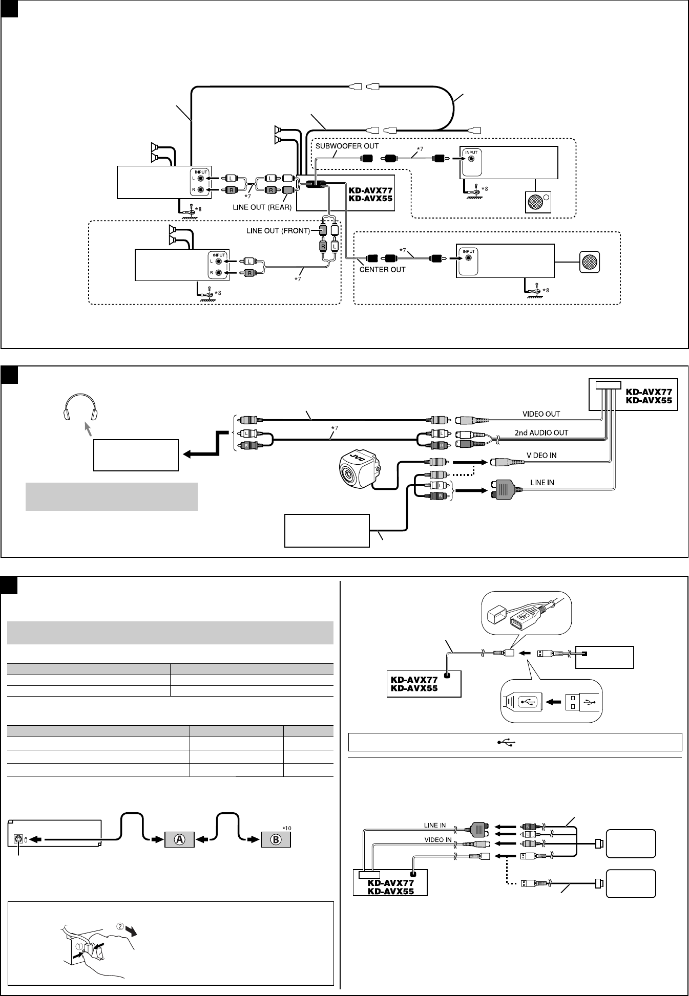
Connecting the external amplifiers
Connecting external components
USB device
Hold the connector top tightly (1),
then pull it out (2).
To disconnect the connector
iPod/iPhone
iPod/iPhone
KS-U30
You cannot connect a computer to the USB ( ) terminal of the unit.
*11 When using the cable, make sure <iPod(Off)> is selected for <AV Input> (see page 19 of the
INSTRUCTIONS).
• iPod is a trademark of Apple Inc., registered in the U.S. and other countries.
• iPhone is a trademark of Apple Inc.
Connecting the iPod or iPhone device to the USB terminal
You can connect the iPod or the iPhone to the USB terminal using the following cables:
– To listen to the music: USB 2.0 cable (accessory of the iPod/iPhone)
– To watch the video: USB Audio and Video cable for iPod/iPhone—KS-U30 (not supplied)*11
You can connect amplifiers to upgrade your car stereo system.
• Connect the remote lead (blue with white stripe) to the remote lead of the other equipment so that it can be controlled through this unit.
• For amplifier only:
– After you have connected the center speaker, make sure to activate the center speaker; otherwise, no sound comes out of the connected center speaker, see page 17 of the INSTRUCTIONS.
– Disconnect the speakers from this unit, and connect them to the amplifier. Leave the speaker leads of this unit unused.
– You can switch off the built-in amplifier and send the audio signals only to the external amplifier(s) to get clear sounds and to prevent internal heat buildup. See page 24 of the INSTRUCTIONS.
*7 Audio cord (not supplied)
*8 Firmly attach the ground wire to the metallic body or to the chassis of the car—to the place uncoated with paint
(if coated with paint, remove the paint before attaching the wire). Failure to do so may cause damage to the unit.
USB devices
Remote lead
Rear speakers
JVC Amplifier
Subwoofer
JVC Amplifier
Remote lead (Blue with white stripe)
Y-connector (not supplied for this unit)
To the remote lead of other equipment or power antenna if any
Front speakers
B
D
Front speakers
JVC Amplifier
JVC Amplifier
Connections for external component playback
C
KS-HP2
Cordless headphones (not supplied) *9
*9 To listen to disc playback sound while in Dual Zone
operations (see page 43 of the INSTRUCTIONS).
Camcorder, Navigation
System, etc.
Video cord (not supplied)
KV-CM1
Rear view camera (not supplied)
2nd monitor
(KV-MR9010, etc.)
Audio/video cords (not supplied)
Normally connect an NTSC monitor. When you watch
the video on iPod or external component, connect a
monitor compatible with both NTSC and PAL.
CD changer jack
When connecting the external components, refer also to the manuals supplied for the components
and adapters.
CAUTION:
Before connecting the external components, make sure that the unit is turned off.
You can connect the following JVC components to the CD changer jack.
JVC Component Model name
CD changer (CD-CH) CH-X1500 etc.
JVC DAB tuner KT-DB1000
You can also connect the following components through the various JVC adapters.
• Connection cords may need to be purchased separately.
Component Adapter Model name
iPod Interface adapter for iPod KS-PD100
Portable audio player with line output jacks Line input adapter KS-U57
Portable audio player with 3.5 mm stereo mini jack AUX input adapter KS-U58
When connecting two components, it is recommended that you connect them in series as explained
below.
*10 To use these components, set the external input setting correctly (see page 19 of the INSTRUCTIONS).
A KT-DB1000
B
*10 CD-CH / KS-PD100 / KS-U57 / KS-U58
KD-AVX77/KD-AVX55
Center speaker
Instal_KDAVX7755[A]f.indb 4Instal_KDAVX7755[A]f.indb 4 09.4.3 11:51:14 AM09.4.3 11:51:14 AM
