JVC KD DV5504UI Install1_KD DV5506_008A_f User Manual GET0606 008B
KD-DV5505A KD-DV5505A GET0606-008B English, INSTALLATION MANUAL
KD-DV5506A KD-DV5506A GET0606-008B English, INSTALLATION MANUAL
KD-DV5504UI KD-DV5504UI INSTALLATION MANUAL GET0606-008B
User Manual: JVC KD-DV5504UI KD-DV5504UI English, INSTALLATION MANUAL
Open the PDF directly: View PDF ![]() .
.
Page Count: 4
1
KD-DV5506/KD-DV5505/
KD-DV5504
Installation/Connection Manual
GET0606-008B
[A/UI]
0409DTSMDTJEIN
EN
This unit is designed to operate on 12 V DC, NEGATIVE ground electrical systems. If your vehicle does
not have this system, a voltage inverter is required, which can be purchased at JVC car audio dealers.
WARNINGS
• DO NOT install any unit or wire any cable in a location where;
– it may obstruct the steering wheel and gearshift lever operations.
– it may obstruct the operation of safety devices such as air bags.
– it may obstruct visibility.
• DO NOT operate the unit while driving.
• If you need to operate the unit while driving, be sure to look around carefully.
• The driver must not watch the monitor while driving.
If the parking brake is not engaged, “DRIVER MUST NOT WATCH THE MONITOR WHILE
DRIVING.” appears on the monitor, and no playback picture will be shown.
– This warning appears only when the parking brake lead is connected to the parking brake
system built in the car.
To prevent short circuits, we recommend that you disconnect the battery’s negative terminal and make all
electrical connections before installing the unit.
• Be sure to ground this unit to the car’s chassis again after installation.
Notes:
• Replace the fuse with one of the specified rating. If the fuse blows frequently, consult your JVC car audio
dealer.
• It is recommended to connect speakers with a maximum power of more than 50 W (both at the
rear and at the front, with an impedance of 4 Ω to 8 Ω). If the maximum power is less than 50 W,
change <AMP GAIN> setting to prevent the speakers from being damaged (see page 39 of the
INSTRUCTIONS).
• To prevent short circuits, cover the terminals of the UNUSED
leads with insulating tape.
• The heat sink becomes very hot after use. Be careful not to
touch it when removing this unit.
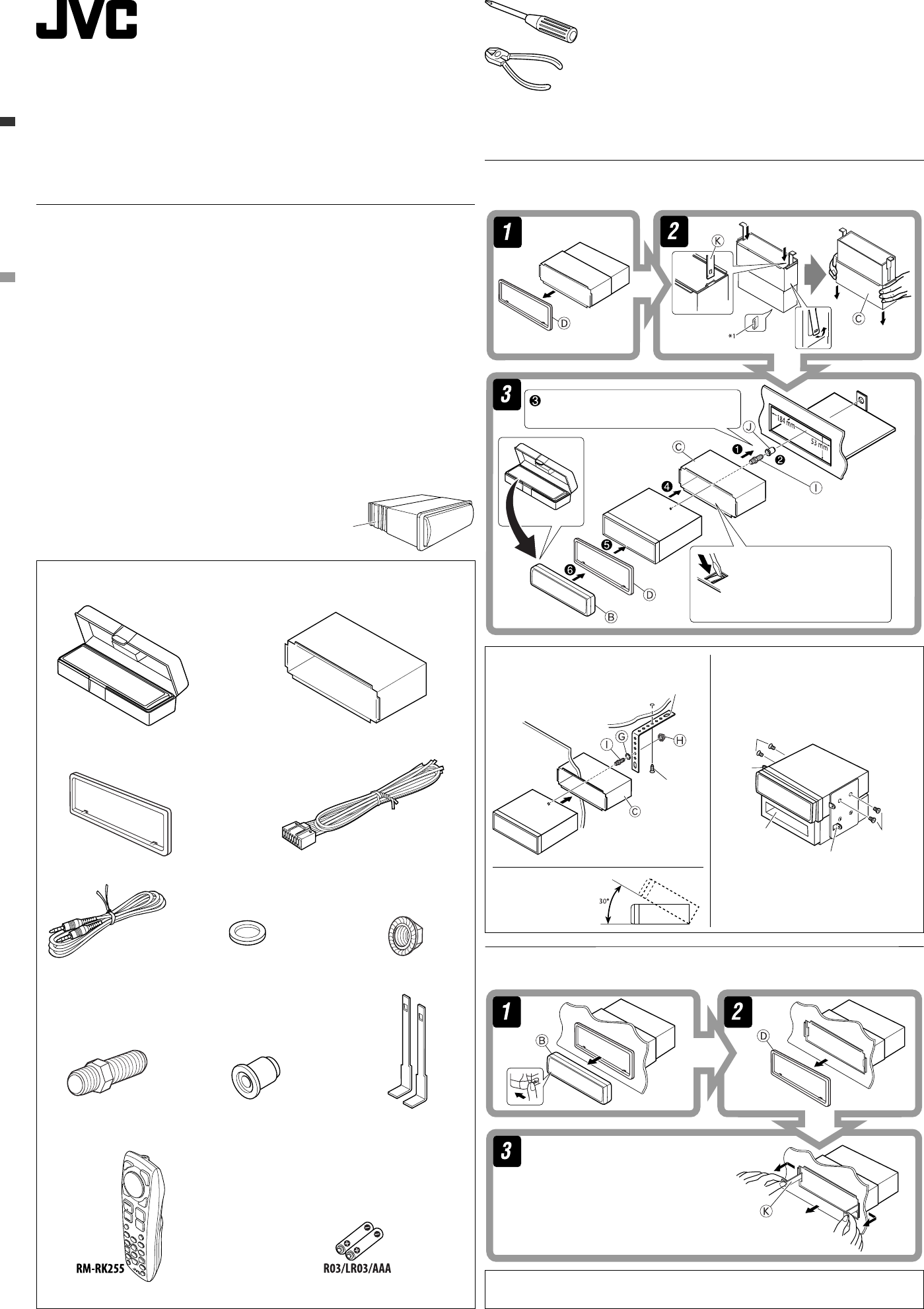
INSTALLATION (IN-DASH MOUNTING)
The following illustration shows a typical installation. If you have any questions or require information
regarding installation kits, consult your JVC car audio dealer or a company supplying kits.
• If you are not sure how to install this unit correctly, have it installed by a qualified technician.
Removing the unit
Before removing the unit, release the rear section.
© 2009 Victor Company of Japan, Limited
*1 When you stand the unit, be careful not to damage the fuse on the rear.
*2 Not supplied for this unit.
J Rubber cushion
G Washer (ø5) H Lock nut (M5)
I Mounting bolt (M5 × 20 mm)
Parts list for installation and connection
If any item is missing, consult your JVC car audio dealer immediately.
K Handles
L Remote controller M Battery
A / B Hard case/Control panel C Sleeve
D Trim plate E Power cord
Heat sink
F AV mini plug cable
Insert the two handles, then pull them as
illustrated so that the unit can be removed.
When installing the unit without
using the sleeve
In a Toyota car for example, first remove the car
radio and install the unit in its place.
When using the optional stay
Note:
When installing the unit on the mounting
bracket, make sure to use the 8 mm-long screws.
If longer screws are used, they could damage the
unit.
Install the unit at an
angle of less than 30˚.
Screw (option)
Stay (option)
Fire wall
Dashboard
Bracket *2
Flat head screws
(M5 × 8 mm) *2
Pocket
Bracket *2
Flat head screws
(M5 × 8 mm) *2
Bend the appropriate tabs to hold
the sleeve firmly in place.
Do the required electrical connections.
Install1_KD-DV5506_008B_ff.indd 1Install1_KD-DV5506_008B_ff.indd 1 4/21/09 2:00:16 PM4/21/09 2:00:16 PM
2
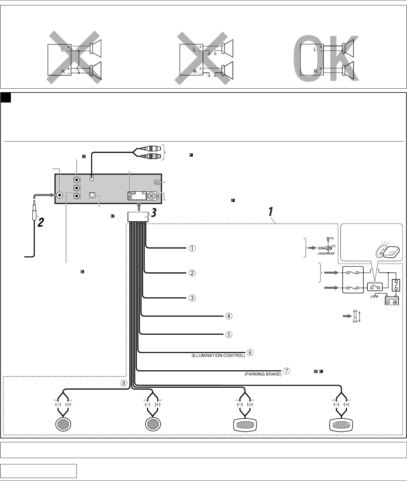
PRECAUTIONS on power supply and speaker connections:
• DO NOT connect the speaker leads of the power cord to the car battery; otherwise, the unit will be seriously damaged.
• BEFORE connecting the speaker leads of the power cord to the speakers, check the speaker wiring in your car.
To external components (see diagram )
Light green
VIDEO OUT
(see diagram )
DIGITAL OUT
(see diagram )
A
(see diagram , )
Before connecting: Check the wiring in the vehicle carefully. Incorrect connection may cause serious damage to this unit.
The leads of the power cord and those of the connector from the car body may be different in color.
1 Connect the colored leads of the power cord in the order specified in the illustration below.
2 Connect the antenna cord.
3 Finally connect the wiring harness to the unit.
15 A fuse
Black
Blue with white stripe
Red
Yellow *4
To metallic body or chassis of the car
Ignition switch
Fuse block
To an accessory terminal in the fuse block
To the remote lead of other equipment (200 mA max.)
To a live terminal in the fuse block connecting to the car battery
(bypassing the ignition switch) (constant 12 V)
LINE OUT
(see diagram )
Rear ground terminal
Left speaker (front) Right speaker (front) Left speaker (rear) Right speaker (rear)
PurplePurple with black stripeGreenGreen with black stripeGrayGray with black stripeWhiteWhite with black stripe
Typical connections
ELECTRICAL CONNECTIONS
Antenna terminal
To car light control switch
Orange with white stripe
LINE IN
(see diagram )
*3 Not supplied for this unit.
*4 Before checking the operation of this unit prior to installation, this lead must be connected, otherwise power cannot be turned on.
To the automatic antenna if any (250 mA max.)
Blue
TROUBLESHOOTING
• The fuse blows.
* Are the red and black leads connected correctly?
• Power cannot be turned on.
* Is the yellow lead connected?
• No sound from the speakers.
* Is the speaker output lead short-circuited?
• Sound is distorted.
* Is the speaker output lead grounded?
* Are the “–” terminals of L and R speakers grounded in common?
• Noise interfere with sounds.
* Is the rear ground terminal connected to the car’s chassis using shorter and thicker cords?
• This unit becomes hot.
* Is the speaker output lead grounded?
* Are the “–” terminals of L and R speakers grounded in common?
• This unit does not work at all.
* Have you reset your unit?
Install1_KD-DV5506_008B_ff.indd 2Install1_KD-DV5506_008B_ff.indd 2 4/21/09 2:00:20 PM4/21/09 2:00:20 PM
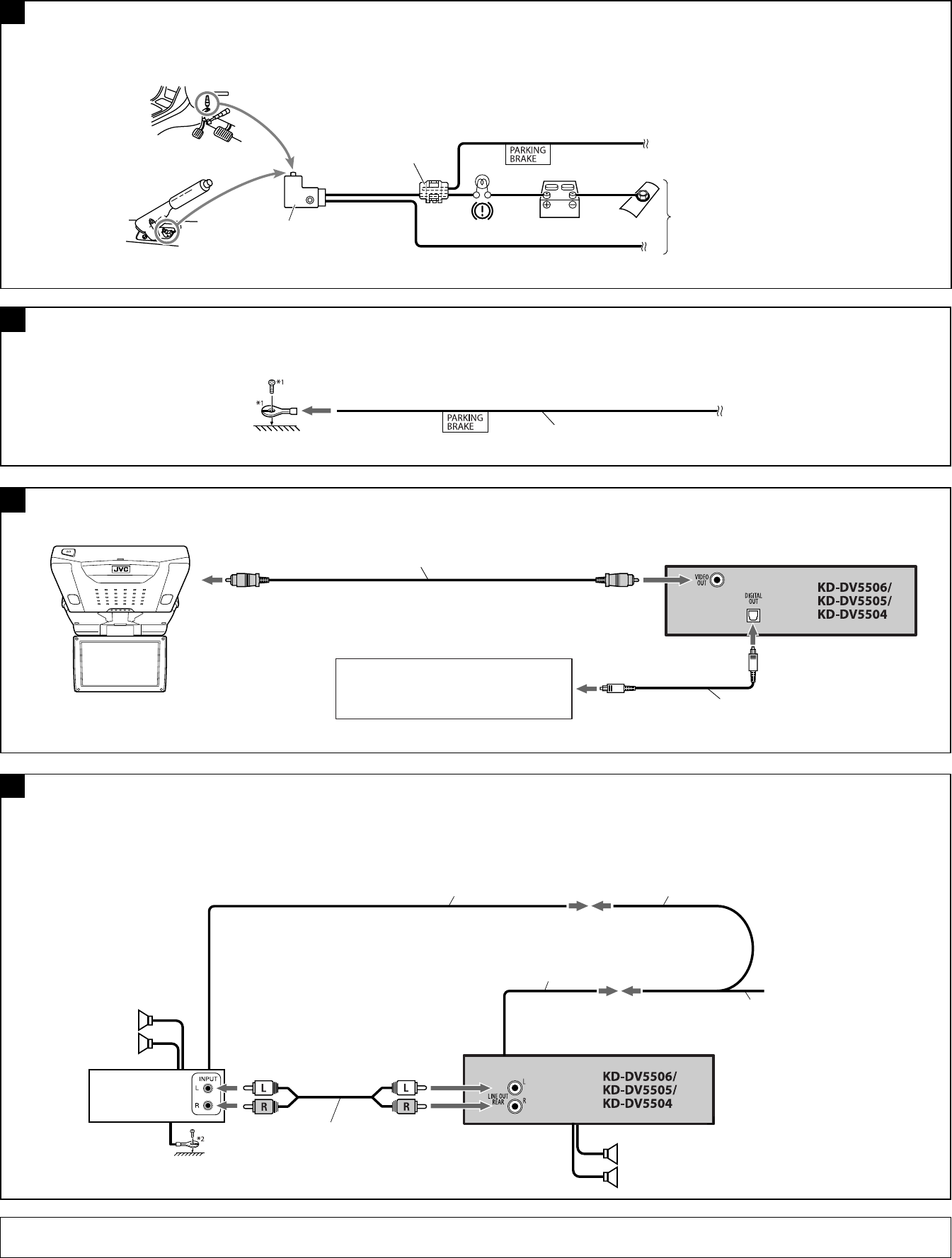
3
B
Connecting the parking brake wire (When installing the monitor in a location where it can be seen by the driver)
Connect the parking brake wire to the parking brake system built in the car.
Connect the parking brake wire to metallic body or chassis of the car.
Connecting the parking brake wire (When installing the monitor in a location where it cannot be seen by the driver)
C
D
Parking brake wire (light green)
To metallic body or chassis of the car
Parking brake switch (inside the car)
Parking brake
Parking brake wire (light green)
E
*1 Not supplied for this unit.
*2 Firmly attach the ground wire to the metallic body or to the chassis of the car—to the place uncoated with paint (if coated with paint, remove the paint before attaching the wire). Failure to do so may cause damage to the unit.
Connecting the external amplifier
You can connect an amplifier to upgrade your car stereo system.
• Connect the remote lead (blue with white stripe) to the remote lead of the other equipment so that it can be controlled through this unit.
• Disconnect the speakers from this unit, connect them to the amplifier. Leave the speaker leads of this unit unused.
Rear speakers
JVC Amplifier
Remote lead Y-connector *1
Remote lead (blue with white stripe)
To the remote lead of other equipment or automatic antenna if any
Front speakers
Required connections for video playback
Audio/video control amplifier or the decoder compatible
with the multichannel digital sources
KV-MR9010
9-INCH WIDESCREEN MONITOR *1
Digital optical cable *1 (only for DVD playback)
Video cord *1
Signal cord *1
Crimp connector *1
Install2_KD-DV5506_008B_ff.indd 3Install2_KD-DV5506_008B_ff.indd 3 4/21/09 2:06:27 PM4/21/09 2:06:27 PM
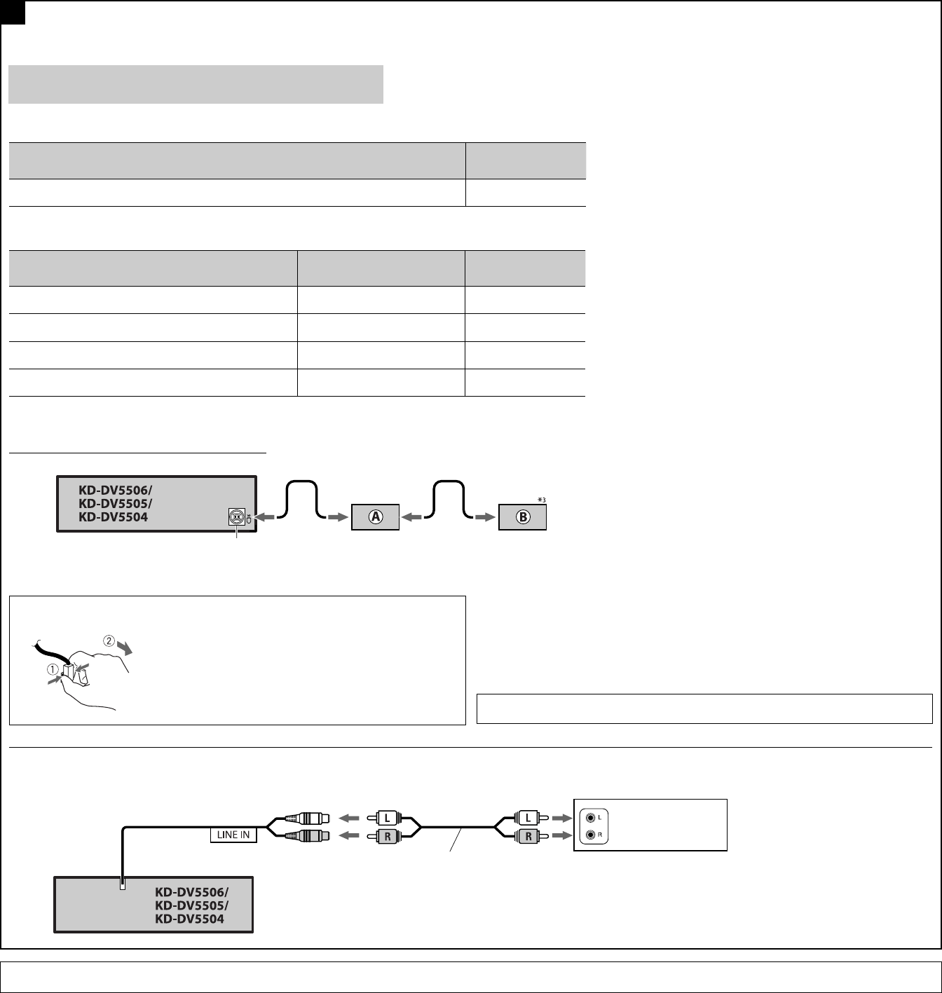
4
When connecting the external components, refer also to the manuals supplied for the components and adapters.
CAUTION:
Before connecting the external components, make sure that the unit is turned off.
You can connect the following JVC components to the CD changer jack.
JVC component Model name
CD changer (CD-CH) CH-X1500, etc.
You can also connect the following components through the various JVC adapters.
• Connection cords may need to be purchased separately.
Component Adapter Model name
Bluetooth device Bluetooth adapter KS-BTA200
iPod Interface adapter for iPod KS-PD100
Portable audio player with line output jacks Line input adapter KS-U57
Portable audio player with 3.5 mm stereo mini jack AUX input adapter KS-U58
When connecting more than one component (maximum: two), it is recommended that you connect the components in series as explained below.
*3 To use these components, set the external input setting correctly (see page 39 of the INSTRUCTIONS).
Connecting the external components
F
iPod is a trademark of Apple Inc., registered in the U.S. and other countries.
To disconnect the connector
Hold the connector tightly ( 1 ), then pull it out ( 2 ).
CD changer jack
External component
You can also connect an external component to the LINE IN plugs of the unit using a signal cord (not supplied).
Signal cord (not supplied for this unit)
A KS-BTA200
B *3 CD-CH / KS-PD100 / KS-U57 / KS-U58
When connecting two components in series
Install2_KD-DV5506_008A_f.indd 4Install2_KD-DV5506_008A_f.indd 4 2/25/09 2:39:38 PM2/25/09 2:39:38 PM
