JVC KD G425UT G425 010A User Manual GET0350
KD-G425UT KD-G425UT INSTALLATION MANUAL (Asia) GET0350-010A
User Manual: JVC KD-G425UT KD-G425UT English, Traditional Chinese, INSTALLATION MANUAL
Open the PDF directly: View PDF ![]() .
.
Page Count: 4
KD-G425
Installation/Connection Manual
ϰ༬ો˿̱
GET0350-010A
[UT]
1105DTSMDTJEIN
EN, CT
ENGLISH
This unit is designed to operate on 12 V DC, NEGATIVE ground electrical systems. If your vehicle does
not have this system, a voltage inverter is required, which can be purchased at JVC car audio dealers.
ˁ̂
ʹጅ෮̈́՟·ڈޠ12 V é࠸ોϚڅྑກԧéϨسڄԾቩԅЉɾྐԦç۱ᄔ࠱ɾࡴྐ
Ꮻ᜵ಗç̣̈́ϚJVCԆԾࡖᛏ˜ኀੋளකռé
1
© 2005 Victor Company of Japan, Limited
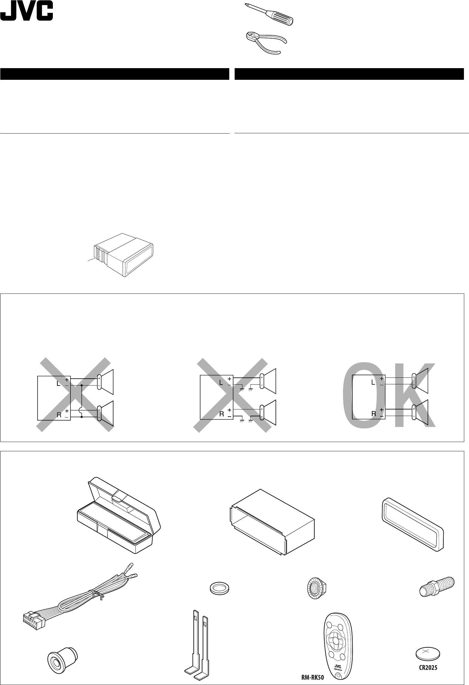
J
Handles
ػܓӕ˾
F
Washer (ø5)
࿑(ø5)
G
Lock nut (M5)
ᕬ׆ᒘ(M5)
H
Mounting bolt (M5 × 20 mm)
ႌ֣ᒘन(M5 × 20 mm)
I
Rubber cushion
ጁሗՎ࿑
A / B
Hard case/Control panel
ഢୢվࡒػ
C
Sleeve
͙ࢭጅೋ
D
Trim plate
༫ྟख
E
Power cord
ྐཔ·ڄለӧ
Parts list for installation and connection
The following parts are provided for this unit. After checking them, please set them correctly.
Έءϰ༬֝ોڅྒྷέ
ʓλྒάݵᎲʹጅಏաڄéଡᓭ̣݈çᇧڄઅմ༫é
Heat sink
ಞᇊ̕
WARNINGS
To prevent short circuits, we recommend that you disconnect the battery’s negative terminal and make all
electrical connections before installing the unit.
• Be sure to ground this unit to the car’s chassis again after installation.
Notes:
• Replace the fuse with one of the specified rating. If the fuse blows frequently, consult your JVC car audio
dealer.
• It is recommended to connect to the speakers with maximum power of more than 50 W (both at
the rear and at the front, with an impedance of 4 Ω to 8 Ω). If the maximum power is less than
50 W, change “AMP GAIN” setting to prevent the speakers from being damaged (see page 13 of the
INSTRUCTIONS).
• To prevent short-circuit, cover the terminals of the UNUSED leads with insulating tape.
• The heat sink becomes very hot after use. Be careful not to touch it when removing this unit.
ᙲѿ
Վ̊ഠཔçܿᙯϚϯ༫ʹጅ˃ۮçᔃළྐЖڄ࠷çՓӕЉྐཔ௲Ϧé
ëϰ༬ҭ݉ੁͬઆ͵ጆڅϚሉࡍ๙ોгԿԾê
ٍิ!
ëӕۘᎳീӦಗᖃ׆࠷மࡩڄۘᎳീéϨسۘᎳീગጛᖢçቁώJVCԆԾࡖᛏ˜ኀੋ༿é
ë݈֜ۮಙᑵڄఛʨ᎔ʈ̷ᏻʨؠ50 Wçմۇӏ4 Ω - 8 ΩéϨسఛʨ̷ʮؠ
50 Wçቁቆओ“AMP GAIN”׆ࡩç̣Վ̊ಙᑵ๑ᖢéኌ՟·იاएڄ୶ࡗé
ëՎ̊ྐഠཔçቁ·ഽሇઘ̸уͶՠΈྐለڄၷʪé
ëʹጅ՟·݈çಞᇊ݃̕ᇊéϕЏçϚ୰̳ʹጅइçʮ˻ʿ࠱᙮ညಞᇊ̕é
PRECAUTIONS on power supply and speaker connections:
• DO NOT connect the speaker leads of the power cord to the car battery; otherwise, the unit
will be seriously damaged.
• BEFORE connecting the speaker leads of the power cord to the speakers, check the speaker wiring in
your car.
ྑກ֝ಚᑶወોሉٍิො!
ë˞ˢӖಚᑶወዘሉોᏄોгྑЗèѵ۲͵ጆઆᘸࡍ๒ᖣê
ëϚӕಙᑵለᏃвಙᑵ˃ۮçᐓފԆԾʕڄಙᑵለཔé
K
Remote controller
ჲ
L
Battery
ྐЖ
KD-G425-010A.indd 1KD-G425-010A.indd 1 24/11/05 2:57:15 PM24/11/05 2:57:15 PM
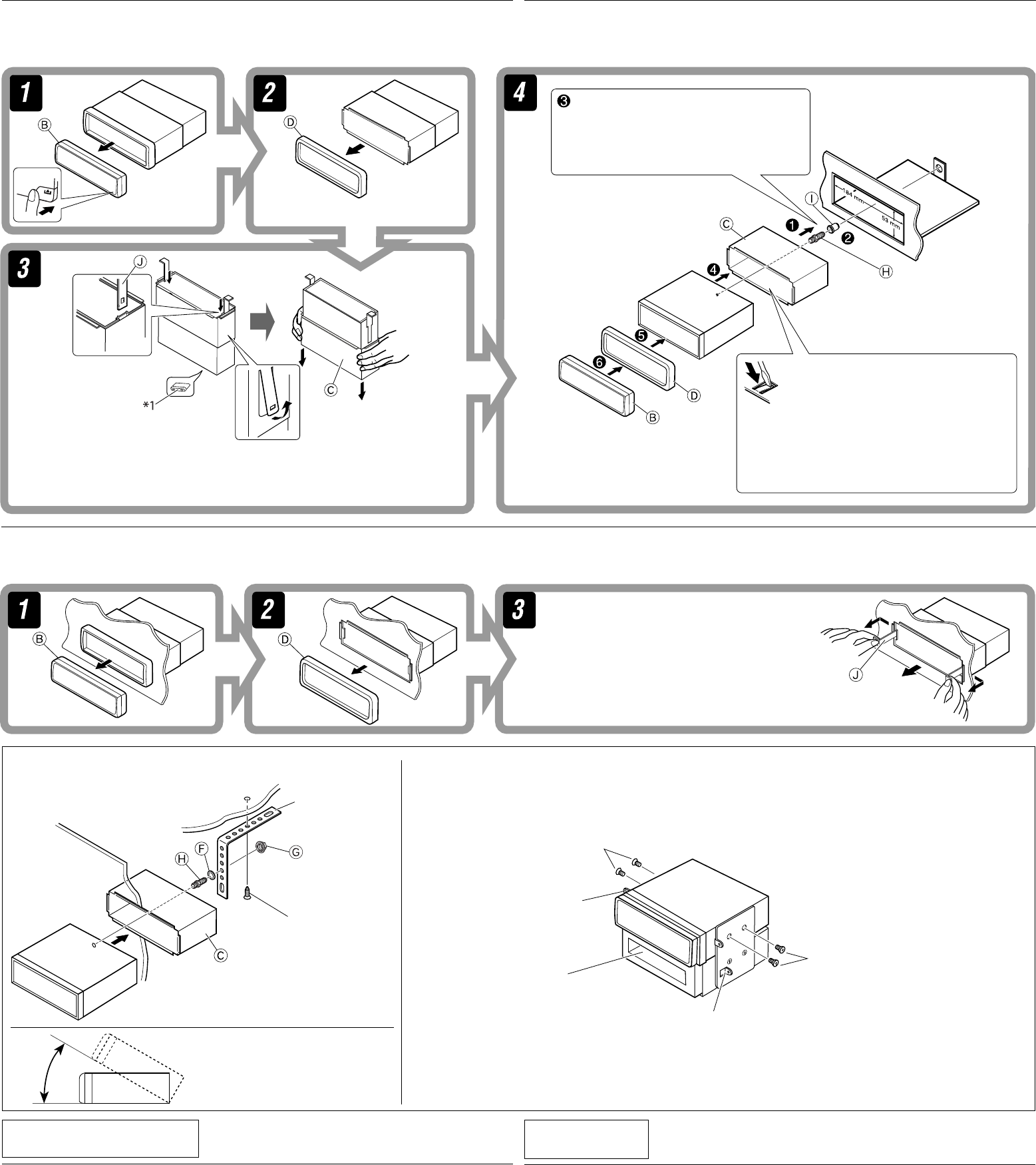
When installing the unit without using the sleeve / ࠝˀՠΈ͚ࢮጆೌϰ༬͵ጆ
In a Toyota car for example, first remove the car radio and install the unit in its place.
̣ᕙΉ(TOYOTA) ԆԾբ ࡛ζ֊̳ԆԾЂࡖጅç݈અʹጅ༫ʈմڏ̳ڄтé
When using the optional stay / ࠝΈ́ᆊނ
*2
Not supplied for this unit.
*2
ʿᎲʹጅಏաé
Flat type screws (M5 × 8 mm)*2
ͦᏃᒘീਐ (M5 × 8 mm)*2
Pocket
ڏೋ
Flat type screws (M5 × 8 mm)*2
ͦᏃᒘീਐ (M5 × 8 mm)*2
2
Bracket*2
Ёࣙ*2
Removing the unit
Before removing the unit, release the rear section.
Insert the two handles, then pull them as
illustrated so that the unit can be removed.
ݝ࿌Εçઅղ̕ػܓӕ˾ʈ̿ᆥç݈ძᗌ
ϙનղώ͙ղ̕ӕ˾çʹጅᎲ˃̳é
։͵ጆ
Ϛ؛ֈʹጅۮçᏻઅʹጅ݈௰ڄ֣׆֜௰˜ᖑළé
Do the required electrical connections.
නмᄔڄྐཔé
*1 When you stand the unit, be careful not to damage the fuse on the rear.
*1 ৹ʹጅइçʮ˻ʿ࠱๑ᖢנ௰ڄۘᎳീé
Bend the appropriate tabs to hold the
sleeve firmly in place.
Ҿᛮጅೋڄߴдçӕ͙ࢭጅೋԕ֣Ϛᄭڷ
ػ˖é
INSTALLATION (IN-DASH MOUNTING)
The following illustration shows a typical installation. If you have any questions or require information
regarding installation kits, consult your JVC car audio dealer or a company supplying kits.
• If you are not sure how to install this unit correctly, have it installed by a qualified technician.
ϰ༬༬éׇ֤ϛᄮڸؼ˗
ʓࡒڄ࿌༱ڷΕʄյܓڄϯ༫ദҺéϨسЉᖅçᄔ࠱Љᘕࢭ˔άڄཊऄçቁώJVC
ԆԾࡖᛏ˜ኀੋࢭ˔άաᏻ˙͌༿é
ëϨسʿᇧ׆Ϩщᇧϙϯ༫ʹጅçᏻቁϐतڄӑிʆ࢜գϯ༫é
Bracket*2
Ёࣙ*2
Screw (option)
ᒘീਐ·ڄ
Stay (option)
̀ᆉށ·ڄ
Fire wall
Վ̑ػ
Dashboard
ᄭڷػ
Install the unit at an angle of less
than 30˚.
અʹጅϯ༫Ϛ˲ؠ30˚ڄԴܾé
Note : When installing the unit on the mounting bracket, make sure to use the 8 mm-long screws. If longer screws are
used, they could damage the unit.
ٍิ !ӕʹጅϯ༫ϚЁࣙʕइçੀͫ՟·8 mmۂڄᒘീਐéϨ՟·ཫۂڄᒘീਐç๑ᖢʹጅé
TROUBLESHOOTING
• The fuse blows.
* Are the red and black leads connected correctly?
• Power cannot be turned on.
* Is the yellow lead connected?
• No sound from the speakers.
* Is the speaker output lead short-circuited?
• Sound is distorted.
* Is the speaker output lead grounded?
* Are the “–” terminals of L and R speakers grounded in common?
• Noise interfere with sounds.
* Is the rear ground terminal connected to the car’s chassis using shorter and thicker cords?
• This unit becomes hot.
* Is the speaker output lead grounded?
* Are the “–” terminals of L and R speakers grounded in common?
• This unit does not work at all.
* Have you reset your unit?
ݮᄑਜ
•ۙᎴുጜᔄê
*ᐓފ߹иለᏃ֜෨иለᏃݵѴ᙮ᇧ%
•ྑກˀ়ોê
*ᐓފ෦иለᏃݵѴʕ%
•ಚᑶወԆЊᑶࡗê
*ᐓފಙᑵ᎔̳ለᏃݵѴഠཔ%
•ᑶࡗ͜ॳê
*ᐓފಙᑵ᎔̳ၷʪݵѴϙ%
*ᐓފಙᑵڄͣ(L)è͆(R) ၷʪڄ࠷(–) ݵѴθψϙ%
•ࡗʹᓿࡗᛐê
*݈ϙၷʪႩԾԽݵѴ՟·ཛഠ֜ཛ۹ڄྐለ%
•͵ጆഛᇋê
*ᐓފಙᑵ᎔̳ၷʪݵѴϙ%
*ᐓފಙᑵڄͣ(L)è͆(R) ၷʪڄ࠷(–) ݵѴθψϙ%
•͵ጆҭθˀ়ይіê
*ݵѴʵࡌڄጅஇ%
KD-G425-010A.indd 2KD-G425-010A.indd 2 24/11/05 2:57:23 PM24/11/05 2:57:23 PM
3
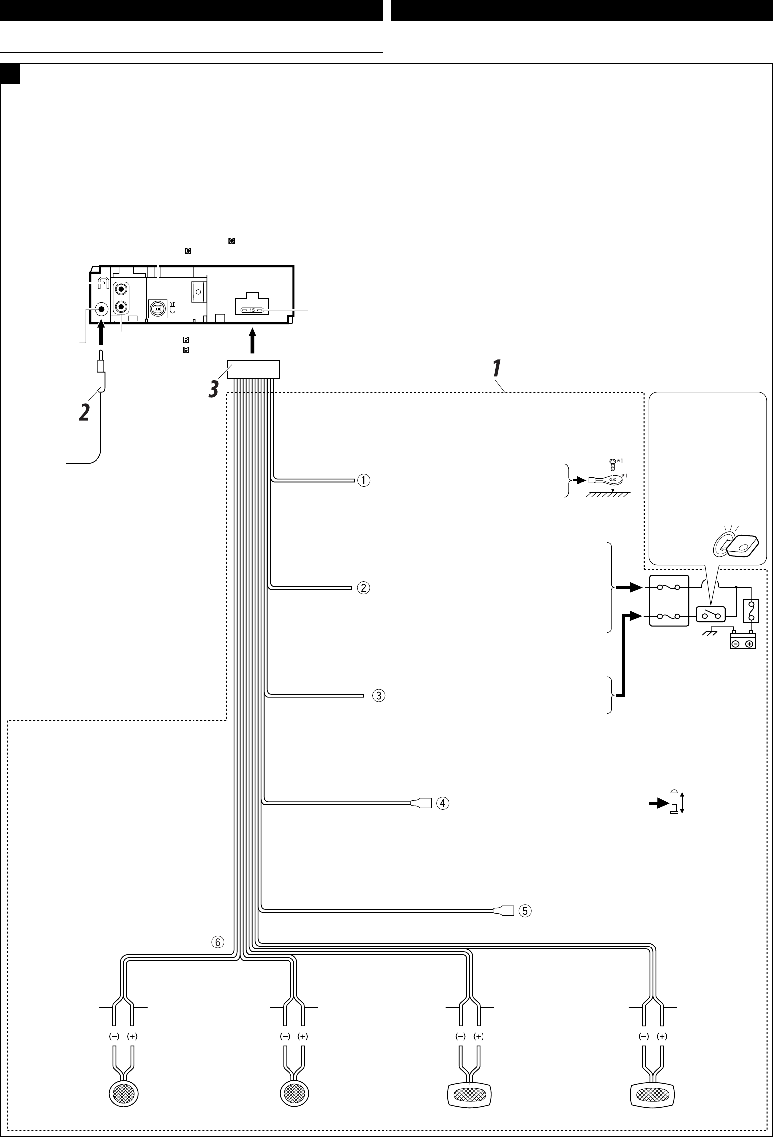
Before connecting: Check the wiring in the vehicle carefully. Incorrect connection may cause serious
damage to this unit.
The leads of the power cord and those of the connector from the car body may be different in color.
1 Connect the colored leads of the power cord in the order specified in the illustration below.
2 Connect the antenna cord.
3 Finally connect the wiring harness to the unit.
Purple
ാи
Purple with black stripe
ാиઘЉ෨иঙ
Green
ႋи
Green with black stripe
ႋиઘЉ෨иঙ
Gray
Ни
Gray with black stripe
НиઘЉ෨иঙ
White
Ύи
White with black stripe
ΎиઘЉ෨иঙ
ENGLISH ˁ̂
ોሉۯ!̥அᐓފԆԾ˖ڄለཔéʿᇧڄለࠓʹጅᘷࡌ๑ᖢé
ྐʍለڄ˺ለ֜ԾԽڄ˺ለϚᖄиʕ̈́Љʿψé
1 ՜ຖʓ࿌Ε˃ЎҺྐለڄᖄиለé
2 અ˭ለڄྐለ৹գé
3 ఛ݈çӕለӧڄᏃϚʹጅʕé
Typical connections / նܔڅોሉ̅٘
A
ELECTRICAL CONNECTIONS ྑཕો
To the automatic antenna if any (250 mA max.)
вбੂ˭ለࠜЉ༫ఛʨ250 mA
To the remote lead of other equipment (200 mA max.)
в͏ɾށᄭڄჲለఛʨ200 mA
To metallic body or chassis of the car
вہᚙᝂԆԾנᇟ
To a live terminal in the fuse block connecting to the car battery
(bypassing the ignition switch) (constant 12 V)
вۘᎳീవ˔˖ڄۈᚙၷʪçۘᎳീవ˔ؠԾ༫ྐЖߟ
·ؠअཔᓭ̑ළᘕݔ׆12 V
To an accessory terminal in the fuse block
вۘᎳീవ˔˖ڄۈᚙၷʪ
Right speaker (rear)
͆ಙᑵ݈
Left speaker (rear)
ͣಙᑵ݈
Right speaker (front)
͆ಙᑵۮ
Left speaker (front)
ͣಙᑵۮ
*2
Before checking the operation of this unit prior to
installation, this lead must be connected, otherwise
power cannot be turned on.
*2
ʹጅ͵ϯ༫इçනмʳѕٶٜᐓފ˃ۮç
ͫෝӕለʕçѴ۱ʿළ૧ྐé
15 A fuse
15 AۘᎳീ
Line out (see diagram )
᎔̳ၷʪኌ࿌ڷ
Antenna terminal
˭ለၷʪ
Rear ground
terminal
ʹጅ݈ࠌϙၷʪ
*1 Not supplied for this unit.
*1 ʿᎲʹጅಏաé Ignition switch
ᓭ̑ළᘕ
Fuse block
ۘᎳീవ˔
Black
෨и
Blue with white stripe
ᕇиઘЉΎиঙ
Red
߹и
Yellow *2
෦и*2
Blue
ᕇи
To external components (see diagram )
в͙இάኌ࿌ڷ
KD-G425-010A.indd 3KD-G425-010A.indd 3 24/11/05 2:57:28 PM24/11/05 2:57:28 PM

4
Connecting the external amplifier or subwoofer/ ોг͚௱̸ୋ؟ʩወචࡍљࡗಚᑶወ
You can connect an amplifier to upgrade your car stereo system.
• Connect the remote lead (blue with white stripe) to the remote lead of the other equipment so that it
can be controlled through this unit.
• Disconnect the speakers from this unit, connect them to the amplifier. Leave the speaker
leads of this unit unused.
*3 Firmly attach the ground wire to the metallic body or to the chassis of the car—to the place uncoated with
paint (if coated with paint, remove the paint before attaching the wire). Failure to do so may cause damage
to the unit.
*3 અϙለႩہᚙԾᝂږԆԾנᇟႌંçளᏻ༳ԅЉூٛွᕒႵϨسʵดʕٛွçϚ
ྐለۮçઅٛွս̓éϨسʿᆟਭç̈́๑ᖢʹጅé
̷̣̈́؞ʨ̣ಏجౚԾڄࡖᛏԦé
ëઅჲለᕇиઘЉΎиঙ֜մ̧༫ʕڄჲለ৹գç̣۔̣̈́ཫʹጅනм
ჲé
ëઆಚᑶወ֝͵ጆᔄෆèκોʖ̸ୋ؟ʩወêઆ͵ጆڅಚᑶወોሉ؟ˀΈê
*4 Signal cord (not supplied for this unit)
*4
ۑ༙ྐងʿᎲʹጅಏա
B
Rear speakers
݈ಙᑵ
Remote lead
ჲለ
Remote lead (Blue with white stripe)
ჲለᕇиઘЉΎиঙ
To the remote lead of other equipment or automatic
antenna if any
в͏ɾށᄭڄჲለбੂ˭ለࠜЉ
༫
Y-connector (not supplied for this unit)
Y-ܓለʿᎲʹጅಏա
Front speakers
ۮಙᑵ
Subwoofer
ඟࡌјࡖ
ಙᑵ
Set “L/O MODE” to “REAR” (See page 13 of the INSTRUCTIONS.)
આ“L/O MODE” ׇ “REAR” (ኍՠΈკبऐڅ୷13 ࡘê)
You can also connect a subwoofer to the REAR LINE OUT terminals.
ʛ̣̈́અඟࡌјࡖಙᑵвREAR LINE OUTၷʪé
JVC Amplifier
JVC
̸ୋ؟ʩወ
You can connect a power amplifier for rear speakers.
݈̈́ಙᑵ̷؞ʨé
Set “L/O MODE” to “WOOFER” (See page 13 of the INSTRUCTIONS.)
આ “L/O MODE” ׇ “WOOFER” (ኍՠΈკبऐڅ୷13 ࡘê)
JVC Amplifier
JVC
̸ୋ؟ʩወ
Other external component / յ̨͚ોஈέ
*7 Line Input Adapter KS-U57 (not supplied for this unit)
*7 ྐཔ᎔ʈቱKS-U57 ʿᎲʹጅಏա
• Set “EXT IN” for the external input setting (See page 13 of the INSTRUCTIONS.)
/
આ͚௱᎕ʉׇг“EXT IN” (͚௱᎕ʉ) (ኍՠΈკبऐڅ୷13 ࡘê)
CAUTION / ʯ˼î
• Before connecting the external components , make sure that the unit is turned off.
• ͙௰இά˃ۮçζᇧ׆ʹጅʵᘕé
External component
͚௱ஈέ
3.5 mm stereo mini plug
3.5 mm Θᝂᑵਁіࣙ
External component
͚௱ஈέ
CD changer jack
CD ಗၪࣙ
CD changer, Apple iPod®, or JVC D. player / CDಘၫወéApple iPod® JVC D. player
You can connect these components as illustrated below.
The iPod*5 or D. player can be connected using an interface adapter (not supplied)—KS-PD100 (for
iPod) or KS-PD500 (for D. player).
*6 Connecting cord supplied for your CD changer
*6 ڄCD ಗၪకڄྐង
Connecting the external components / ોյ̨͚௱
C
• Set “CHANGER” for the external input setting (See page 13 of the INSTRUCTIONS.)
/
આ͚௱᎕ʉׇг“CHANGER” (ಘၫወ) (ኍՠΈკبऐڅ୷13 ࡘê)
Apple iPod (separately purchased)
Apple iPod ͏͙ᒯ
JVC D. player (separately purchased)
JVC D. player ͏͙ᒯ
CD changer jack
CD ಗၪࣙ
JVC CD changer
JVC CDಘၫወ
or
*5 iPod is a trademark of Apple Computer, Inc., registered in the U.S. and other countries.
*5 iPod ݵApple Computer, Inc. ăᙧسྐ༃˙͌ĄϚࠀ˪մ̧ࣁٌ̰ڄੋᆤé
*8 AUX Input Adapter KS-U58 (not supplied for this unit)
*8 AUX᎔ʈቱKS-U58 (ʿᎲʹጅಏա)
̣̈́નʓ࿌Εஇάé
̣̈́՟·ߍࡒቱʿక—KS-PD100 (iPod·KS-PD500* player·
iPod*5 * playeré
KD-G425-010A.indd 4KD-G425-010A.indd 4 11/25/05 11:28:59 AM11/25/05 11:28:59 AM
