JVC KD S600 S600/S550 User Manual FSUN3105 T181
User Manual: JVC KD-S600 KD-S600 English, Simplified Chinese, Arabic, INSTALLATION MANUAL
Open the PDF directly: View PDF ![]() .
.
Page Count: 4
KD-S600/S550
Installation/Connection Manual
ENGLISH
•This unit is designed to operate only on 12 volts DC, NEGATIVE
ground electrical systems.
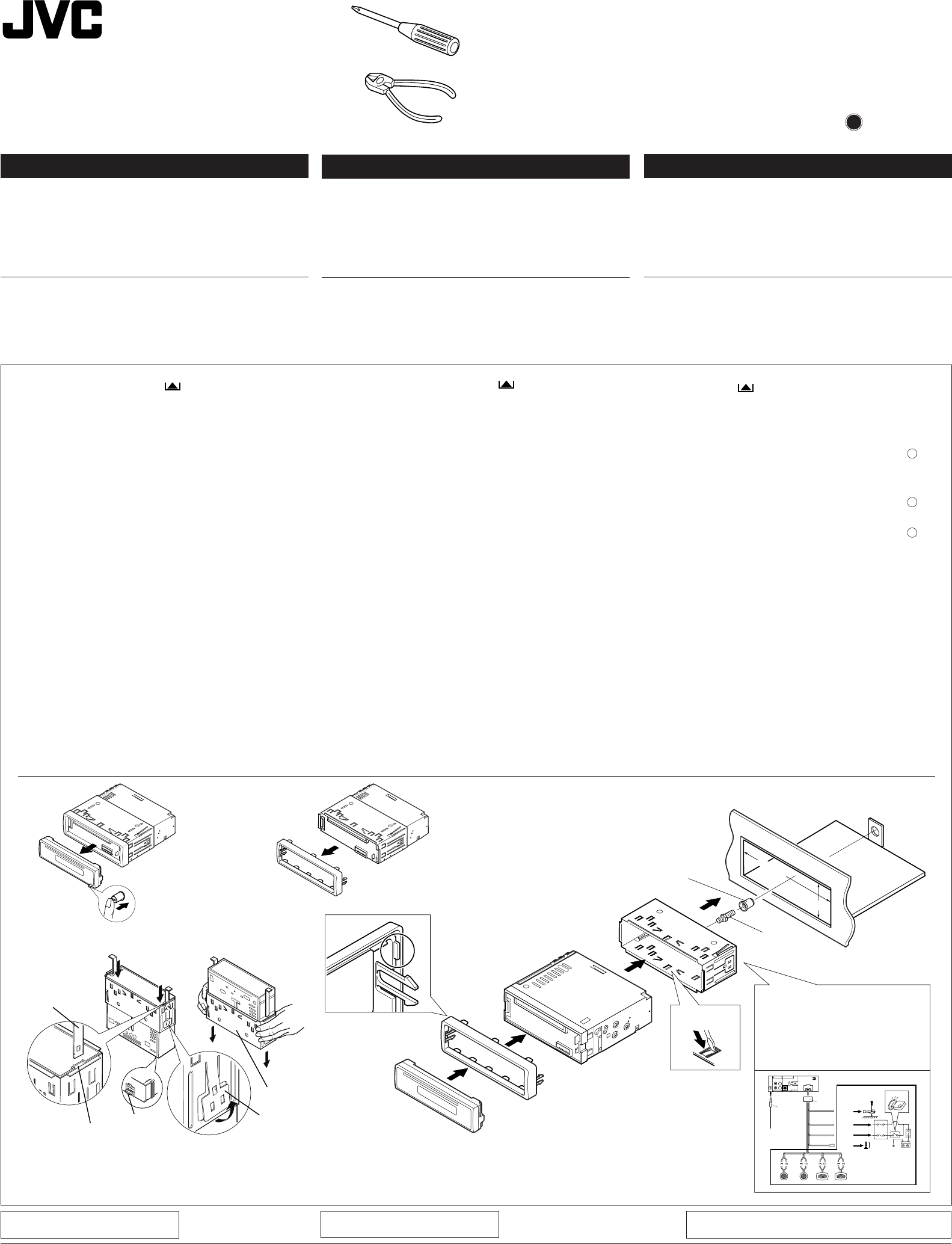
INSTALLATION (IN-DASH
MOUNTING)
•The following illustration shows a typical installation. However,
you should make adjustments corresponding to your specific
car. If you have any questions or require information regarding
installation kits, consult your JVC car audio dealer or a company
supplying kits.
1
Before mounting: Press (Control Panel Release
button) to detach the control panel.
2
Remove the trim plate.
3
Remove the sleeve after disengaging the sleeve locks.
1Stand the unit.
Note: When you stand the unit, be careful not to damage
the fuse on the rear.
2Insert the 2 handles between the unit and the sleeve, as
illustrated, to disengage the sleeve locks.
3Remove the sleeve.
Note: Be sure to keep the handles for future use after
installing the unit.
4
Install the sleeve into the dashboard.
* After the sleeve is correctly installed in the dashboard,
bend the appropriate tabs to hold the sleeve firmly in place,
as illustrated.
5
Fix the mounting bolt to the rear of the unit’s body and place
the rubber cushion over the end of the bolt.
6
Do the required electrical connections explained on the back
of this instructions.
7
Slide the unit into the sleeve until it is locked.
8
Attach the trim plate so that the projection on the trim plate
is fixed to the left side of the unit.
9
Attach the control panel.
J
V
C
wÐdŽwÐdŽ
wÐdŽwÐdŽ
wÐdŽ
•
wzUÐdN —UOð WDÝ«uÐ jI qLFO “UN'« «c¼ rLbI dýU³ DCÆV?UÝ i¹—Qð WOzUÐdN WLE½« ¨Xu ±≤ ¨ ðð
ðð
ð
dd
dd
d
OO
OO
O
VV
VV
V
««
««
«
''
''
'
NN
NN
N
UU
UU
U
““
““
“
®®
®®
®
œœ
œœ
œ
««
««
«
šš
šš
š
qq
qq
q
‡‡‡‡‡
ðð
ðð
ð
UU
UU
U
ÐÐ
ÐÐ
Ð
KK
KK
K
uu
uu
u««
««
«
OO
OO
O
UU
UU
U
——
——
—
……
……
…
©©
©©
©
•O³¹Òl ÆWOU¦*« VOd²« WI¹dÞ wU²« w×O{u²« rÝd« s
w?²?« …—U?O??« Ÿu?½ o?ÐU?D?ð ö?¹b?F?ð q?L?Ž p?O?KŽ V−¹ ¨p–
’uBÐ UuKF* WłUŠ Ë« «—UH²Ý« „UM¼ ÊU «–« ÆUNJK²9
W?O?ðu?B?« …e?N?łô« Ÿ“u? …—U?A?²?Ý« v?łd?¹ ¨VOd²« «Ëœ«
W—U «—UOKJVCÆ«Ëœô« …cN WŽ“u*« WdA« Ë«
±
³?³?
³?³?
³?
q??q??
q??q??
q??
ÐÐ
ÐÐ
Ð
b?b?
b?b?
b?
¡¡
¡¡
¡
««
««
«
²??²??
²??²??
²??
d?d?
d?d?
d?
O??O??
O??O??
O??
V?V?
V?V?
V?
∫∫
∫∫
∫ «{G??j? «d??“ ®“— %d?¹d? u??ŠW? «²×Jr© s «łq Bq uŠW «²×JrÆ ≤≤
≤≤
≤«½eŸ uŠW «e¹MWÆ ≥≥
≥≥
≥
«½eŸ «NOJq «u«w ÐFb Bq ¦³²U «NOJq «u«wÆ
±«Ën «'NU“ ÐAJq ŽLuœÍÆ
öö
öö
ö
ŠŠ
ŠŠ
Š
E?E?
E?E?
E?
WW
WW
W
∫∫
∫∫
∫ ŽM?b ðu?On «'N?U“¨ ðQ?b s Žb? ðCd?— «Ë «ðö· «HOu“ «*ułuœ w «'NW «)KHOW s «'NU“Æ
≤«œšq «*U²5 Ð5 «'NU“ Ë«NOJq «u«w¨ LU ¼u ³5 w «AJq¨ HBq ¦³?²U «NOJq «u«wÆ
≥«½eŸ «NOJq «u«wÆ
ö??ö??
ö??ö??
ö??
ŠŠ
ŠŠ
Š
E???E???
E???E???
E???
W??W??
W??W??
W??
∫∫
∫∫
∫ ¹d???łw?? «;U???E??W?? ŽK???v?? «*???U??U??? s?? «łq?? «ôݲFLU‰ ôŠIU ÐFb ðdOV «'NU“Æ ¥¥
¥¥
¥—V «NOJq «u«w œ«šq ðUÐKu «OU—…Æ
*ÐFb ðdOV «NOJq «u«w KOU œ«šq ðUÐKu «OU—… ÐAJq ×O?`¨ «ŁM?w «_?MW? ÐAJ?q M?UÝV? ²¦?³O?X «N?OJ?q «u«w ÐAJq ×Jr w «*JUÊ «B×O`¨ LU ¼u ³5 w «AJqÆ µµ
µµ
µŁ³ÒX LU— «²dOV ÐU'NW «)KHOW s ¼OJq «'NU“ ËÐFb –p {l «(Au… «*DUÞOW u‚ ½NU¹W «*LU—Æ ∂∂
∂∂
∂
«ŽLq «²uOö «JNdÐUzOW «*DKuÐW LU ¼u AdËÕ šKn ¼cÁ «²FKOLUÆ ∑∑
∑∑
∑«œšq «'NU“ œ«šq «NOJq «u«w Š²v ¹¦³X ÐAJq ×O`Æ ∏∏
∏∏
∏ —Òœułu*« ¡u²M« XO³¦ð r²¹ YO×Ð WM¹e« WŠu V
Æ“UN−K d¹ô« V½U'« vKŽ WM¹e« WŠu vKŽ ππ
ππ
π
—ÒV uŠW «²×JrÆ
O²O²
O²O²
O²
ÒÒÒÒÒ
ØVOd²« ULOKFð VØVOd²« ULOKFð V
ØVOd²« ULOKFð VØVOd²« ULOKFð V
ØVOd²« ULOKFð V
qOu²«qOu²«
qOu²«qOu²«
qOu²« 0100HISFLEJES
EN, CH, AR
FSUN3105 -T181
[U]
184 mm
53 mm
12
See the back page for electrical
connections.
s WOHK)« W×HB« dE½«
ÆWOzUÐdNJ« öOu²« qł«
6
Rubber cushion
4
*
5
7
8
9
4
Õöô«Ë ‰UDŽô« sŽ Y׳«Õöô«Ë ‰UDŽô« sŽ Y׳«
Õöô«Ë ‰UDŽô« sŽ Y׳«Õöô«Ë ‰UDŽô« sŽ Y׳«
Õöô«Ë ‰UDŽô« sŽ Y׳«
•
Æ“uOH« ‚d²×¹Æ“uOH« ‚d²×¹
Æ“uOH« ‚d²×¹Æ“uOH« ‚d²×¹
Æ“uOH« ‚d²×¹ *ø`O× qJAÐ Wuu œuÝô«Ë dLŠô« pK« q¼
•
ÆWOzUÐdNJ« WUD« qOuð sJ1 ôÆWOzUÐdNJ« WUD« qOuð sJ1 ô
ÆWOzUÐdNJ« WUD« qOuð sJ1 ôÆWOzUÐdNJ« WUD« qOuð sJ1 ô
ÆWOzUÐdNJ« WUD« qOuð sJ1 ô *øôuu dHô« pK« q¼
•
ÆUŽUL« s u —bB¹ ôÆUŽUL« s u —bB¹ ô
ÆUŽUL« s u —bB¹ ôÆUŽUL« s u —bB¹ ô
ÆUŽUL« s u —bB¹ ô *øWŽUL« Ãdš pKÝ …dz«œ w dOBIð pUM¼ q¼
•
ÆÁuA uB«ÆÁuA uB«
ÆÁuA uB«ÆÁuA uB«
ÆÁuA uB« *ø÷—ôUÐ ôuu WŽUL« Ãdš pKÝ q¼ * ÈdO« WŽULK å≠ò W³U« ·«dÞô« q¼L vMLO«Ë Rl ÷—ôUÐ Wuu øiFÐ
•
Æ“UN'« s¹Æ“UN'« s¹
Æ“UN'« s¹Æ“UN'« s¹
Æ“UN'« s¹ *ø÷—ôUÐ ôuu WŽUL« Ãdš pKÝ q¼ * ÈdO« WŽULK å≠ò W³U« ·«dÞô« q¼L vMLO«Ë Rl ÷—ôUÐ Wuu øiFÐ
3
10
10
1
231
2
3
5
4
TROUBLESHOOTING
•The fuse blows.
* Are the red and black leads connected correctly?
•Power cannot be turned on.
* Is the yellow lead connected?
•No sound from the speakers.
* Is the speaker output lead short-circuited?
•Sound is distorted.
* Is the speaker output lead grounded?
* Are the “–” terminals of L and R speakers grounded in common?
•Unit becomes hot.
* Is the speaker output lead grounded?
* Are the “–” terminals of L and R speakers grounded in common?
Dashboard
…—UO« uKÐUð
Sleeve
WM¹e« WŠu
Trim plate
Handle
Slot
XO³¦²« W×OH
“uOH«
w«u« qJON«
WU*«
VOd²« —UL
WOÞUD*« …uA(«
w«u« qJON«
Sleeve
Lock Plate
oýÒdOG
Fuse
!"#$
• !"#$% 12V !"#$%&'(
!
!"#$%
• !"#$%&' ()*+,-./0123452 6
!"#$%&'()*+,$-./012-3456
!"#$JVC !"#$%&'()*+,-./0
!
!"
!
!"#$%&'()*
!"
!
• !"#
* !"#$%&'!"#$%()*$+?
• !"#$
* !"#$%&'$?
• !"#$
* !"#$%&'()*+?
• !"
* !"#$%&'()?
* !"#$LR !"– !"?
• !"
* !"#$%&'()?
* !"#$LR !"– !"?
!
1
!" !"#$%& !"#$%
2
!"#
3
!"#$%&'()&*+
1 !"#
!"#$%&'()*+,-./01
2 !"#$%&'(%)*+,-./0123
!"
3 !"#$
!"#$%&'()*+,#-./0123
4
!"#$%&'()
* !"#$%&'()*+,-./01-23!"45
!"#$%&'()*+
5
!"#$%&&'()*+,-./0$ !"1
6
!"#$%&'()%*+,-./01
7
!"#$ %&'( !"
8
!"#$%&' !#()*+,-./0123
9
!"#$
Mounting bolt
•
•
Install.KD-S600/S550[U]/2 02/15/2000, 2:15 PM1
Washer (ø5)
ÂUJŠ« WIKŠ
©µ dD® qOu²«
Hard case
VK ‚ËbM
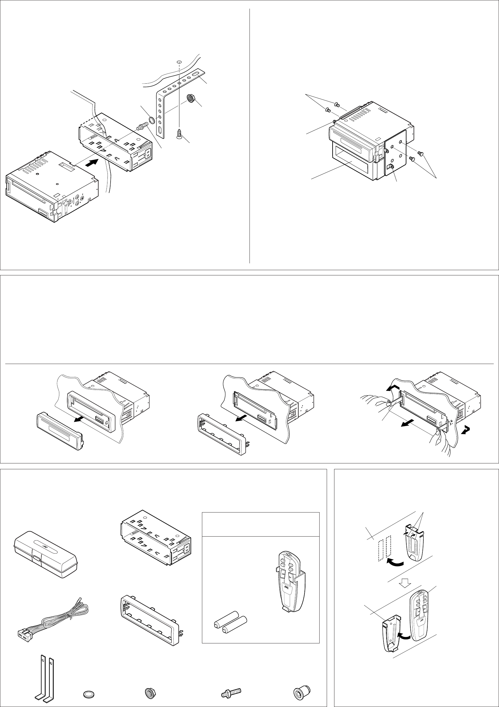
Note: When installing the unit on the mounting bracket, make sure to use the 6 mm-long screws. If
longer screws are used, they could damage the unit.
∫WEŠö∫WEŠö
∫WEŠö∫WEŠö
∫WEŠöWUŠ w ÆrK ∂ ‰uÞ wž«dÐ Âb²Ý« s bQð ¨XO³¦²« WOH² vKŽ “UN'« VOdð bMŽ
Æ“UN'« —d{ Ë« nKð V³¹ Ê« sJ1 p– ÊU ¨rK ∂ s ‰uÞ« wž«dР«b²Ý«
• When using the optional stay
ŽKv ݳOq «*¦U‰¨ w ÝOU—« ½uŸ ðu¹uðU¨ «½eŸ —«œ¹u «OU—… «Ëô ÐFb –p —ÒV «'NU“ w JU½tÆ
•
XO³¦²K wU{« bM «b²Ý« bMŽXO³¦²K wU{« bM «b²Ý« bMŽ
XO³¦²K wU{« bM «b²Ý« bMŽXO³¦²K wU{« bM «b²Ý« bMŽ
XO³¦²K wU{« bM «b²Ý« bMŽ
Dashboard
Fire wall
Sleeve
s W¹UL(« —«bł
o¹d(«
…—UO« uKÐUð
ŠKIW «ŠJUÂ «²uOq
Bracket*
Bracket*
Flat type screws (M5 x 6 mm)*
Flat type screws (M5 x 6 mm)*
* Not included with this unit.
XO³¦²« WOH²*
® …bŽUI« W¹u² wž«dÐM5©rK ∂ ™ *
WOH²
XO³¦²«
*
Removing the unit
•Before removing the unit, release the rear section.
1
Remove the control panel.
2
Remove the trim plate.
3
Insert the 2 handles into the slots, as shown. Then, while gently
pulling the handles away from each other, slide out the unit.
(Be sure to keep the handles after installing it.)
…—UO« uKÐUð s “UN'« Ÿe½…—UO« uKÐUð s “UN'« Ÿe½
…—UO« uKÐUð s “UN'« Ÿe½…—UO« uKÐUð s “UN'« Ÿe½
…—UO« uKÐUð s “UN'« Ÿe½
•ÆwHK)« ¡e'« —dŠ ¨“UN'« Ÿe½ q³
±±
±±
±
ÆrJײ« WŠu Ÿe½«
≤≤
≤≤
≤
ÆWM¹e« WŠu Ÿe½«
≥≥
≥≥
≥Æq?J?A?« w? 5?³? u?¼ U?L? ¨‚u?I?A?« q?š«œ 5?²U*« qšœ«
s?Ž …b?Š«u« «bOFÐ WUDKÐ 5²U*« V×Ý ¡UMŁ« ¨p– bFÐ
Æ×U)« v« “UN'« V×Ý« ¨Èdšô«
©“UN'« VOdð bFÐ 5²U*UÐ pþUH²Š« s bQ𮩓UN'« VOdð bFÐ 5²U*UÐ pþUH²Š« s bQð®
©“UN'« VOdð bFÐ 5²U*UÐ pþUH²Š« s bQ𮩓UN'« VOdð bFÐ 5²U*UÐ pþUH²Š« s bQð®
©“UN'« VOdð bFÐ 5²U*UÐ pþUH²Š« s bQð®
31
WU*«
Handle
2
qOu²«Ë VOd²« ¡«eł« WLzUqOu²«Ë VOd²« ¡«eł« WLzU
qOu²«Ë VOd²« ¡«eł« WLzUqOu²«Ë VOd²« ¡«eł« WLzU
qOu²«Ë VOd²« ¡«eł« WLzU
Æ“UN'« l …œËe WOU²« ¡«ełô«
qJAÐ rN³Odð vłd¹ ¨¡«ełô« Ác¼ h× bFÐ
Æ`O×
Parts list for installation and
connection
The following parts are provided with this unit.
After checking them, please set them correctly.
Rubber cushion
WOÞUD*« …uA(«
Power cord
WOzUÐdNJ« WUD« pKÝ
Handles
UU*«
Lock nut (M5)
® XO³¦²« WuLM5©
Mounting bolt (M5 x 20 mm)
® VOd²« —ULM5©rK ≤∞ ™
Sleeve
w«u« qJON«
Trim plate
WM¹e« WŠu
FOR KD-S600
Remote controller and holder
Batteries
RM-RK22
Installation : Remote Controller (FOR KD-S600)
•Before attaching the double-faced tape, wipe and clean the place
where you plan to attach it.
•ÊUJ*« nE½Ë `« ¨5Nłu« Ë– oö« j¹dA« ‚UB« q³
ÆtOKŽ j¹dA« oBKð Ê« b¹dð Íc«
RM-RK22
Holder
qU(«
Stay (option)
Screw (option)
©wU{«® wždÐ
*Ëe dOžÒÆ“UN'« «c¼ l œ
Remote controller
sŽ rJײ« …bŠË
bFÐ
bFÐ sŽ rJײ« …bŠË ∫ VOd²«bFÐ sŽ rJײ« …bŠË ∫ VOd²«
bFÐ sŽ rJײ« …bŠË ∫ VOd²«bFÐ sŽ rJײ« …bŠË ∫ VOd²«
bFÐ sŽ rJײ« …bŠË ∫ VOd²« q¹œuLK®KD-S600©
Dashboard, etc
uKÐUð
a?« ¨…—UO«
Double-faced tape (not included
with this unit)
dOž® 5NłË Ë– oô j¹dý
©“UN'« «c¼ l od
q¹œuLKKD-S600
qU(«Ë bFÐ sŽ rJײ« …bŠË
U¹—UD³«
R03(UM-4)/AAA(24F)
X³³¦ð bM
©wU{«®
w«u« qJON«
•
w«u« qJON« «b²Ý« ÊËbÐ “UN'« Vdð UbMŽw«u« qJON« «b²Ý« ÊËbÐ “UN'« Vdð UbMŽ
w«u« qJON« «b²Ý« ÊËbÐ “UN'« Vdð UbMŽw«u« qJON« «b²Ý« ÊËbÐ “UN'« Vdð UbMŽ
w«u« qJON« «b²Ý« ÊËbÐ “UN'« Vdð UbMŽ
VOł …bŽUI« W¹u² wž«dÐ
®M5©rK ∂ ™
*
• !"#
!"
!
!"
!
!
• !"#$%&'($
!"#$%&'()*+,6mm !"#$%&' !"()*+,-#
!TOYOTA !"#$%&'()*+,-.)/012&3456
!(M5 x 6 mm)*
* !"#$
*
* !(M5 x 6 mm)*
!
• !"#$%&!"'()*+,-.(/012
1
!"#$
2
!"#
3
!"#$%&'()*+,-."/01234$5
!"#$%&'() *+
!"#$%&'()*+,-.
!"
!"#$%&'(
!"#$%&'()
!"#$%&'()*
!
!"#$%&
!" !"
! (M5)
(ø5) ! (M5 x 20 mm)
• !"#$%&'()*+,-./012
!"# !KD-S600
!
!"#$
KD-S600
!"#$
•
Pocket
Washer
Mounting bolt
VOd²« —UL
Lock nut
XO³¦²« WuL
••
•When installing the unit without using the sleeve
In a Toyota for example, first remove the car radio and install the unit in its place.
•
Install.KD-S600/S550[U]/2 02/15/2000, 2:17 PM2
ENGLISH
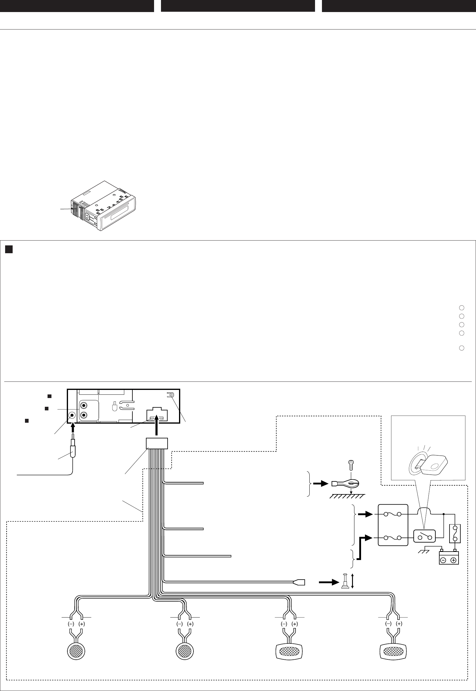
ELECTRICAL CONNECTIONS
To prevent short circuits, we recommend that you disconnect the
battery’s negative terminal and make all electrical connections
before installing the unit. If you are not sure how to install this unit
correctly, have it installed by a qualified technician.
Note:
This unit is designed to operate only on 12 volts DC, NEGATIVE
ground electrical systems. If your vehicle does not have this
system, a voltage inverter is required, which can be purchased at
JVC car audio dealers.
• Replace the fuse with one of the specified rating. If the fuse
blows frequently, consult your JVC car audio dealer.
• If noise is a problem...
This unit incorporates a noise filter in the power circuit. However,
with some vehicles, clicking or other unwanted noise may occur.
If this happens, connect the unit’s rear ground terminal (See
connection diagram below.) to the car’s chassis using shorter
and thicker cords, such as copper braiding or gauge wire. If noise
still persists, consult your JVC car audio dealer.
• Maximum input of the speakers should be more than 40 watts at
the rear and 40 watts at the front, with an impedance of 4 to 8
ohms.
•Be sure to ground this unit to the car’s chassis.
• The heat sink becomes very hot after use. Be careful not to
touch it when removing this unit.
wÐdŽwÐdŽ
wÐdŽwÐdŽ
wÐdŽ
WOzUÐdNJ« öOu²«WOzUÐdNJ« öOu²«
WOzUÐdNJ« öOu²«WOzUÐdNJ« öOu²«
WOzUÐdNJ« öOu²«
*Ml ŠbËÀ ðIBOd w «bË«zd? «JNdÐUzOW¨ ½uw ÐHBq Þd· «³D?U—¹W? «UV? Łr ŽL?q «²u?Oö? «JNd?ÐUzO?W ³q? ðdO?V «'NU“Æ w ŠUW Žb Fd²p ÐJOHOW ðdOV «'NU“ ÐAJq ×O`¨ ¹dłv ðd„ ŽLKOW ðdOV «'NU“ Ah ²h ËR¼q ²dOV ¦q ¼cÁ «ôłNe…Æ
öö
öö
ö
ŠŠ
ŠŠ
Š
EE
EE
E
WW
WW
W
∫∫
∫∫
∫Ib Lr ¼c« «'NU“ OFLq Ij Ðu«ÝDW ðOU—
NN
NN
N
dd
dd
d
ÐÐ
ÐÐ
Ð
UU
UU
U
zz
zz
z
ww
ww
w
³³
³³
³
UU
UU
U
ýý
ýý
ý
dd
dd
d
DC
¨¨
¨¨
¨≤≤
≤≤
≤
±±
±±
±
uu
uu
u
XX
XX
X
¨¨
¨¨
¨
««
««
«
½½
½½
½
EE
EE
E
LL
LL
L
WW
WW
W
NN
NN
N
dd
dd
d
ÐÐ
ÐÐ
Ð
UU
UU
U
zz
zz
z
OO
OO
O
WW
WW
W
ðð
ðð
ð
QQ
QQ
Q
——
——
—
¹¹
¹¹
¹
ii
ii
i
ÝÝ
ÝÝ
Ý
UU
UU
U
VV
VV
VÆ w ŠUW Žb ˳uœ ¦q ¼c« «MEU w ÝOU—ðp¨ ¹−V «Ý²b«Â ×u‰ u²Uè Ë1Js ýd«¡ ¼c« «;u‰ s Ëö¡ «ôłNe… «BuðOW KOU—« U—W JVCÆ•«Ý²³b‰ «HOu“ ÐPšd ¹×Lq ½Hf «IOUÝU «*uuWÆ «–« ðJd— «Š²??d??«‚ «H?O??u??“¨ ¹d??łv? «Ý²??A??U??—… Ëö?¡ «ôłN??e??… «B??u?ðO??W?? KOU—« U—W JVCÆ•«–« UÊ «C−OZ ¼u «*AJKWÆÆÆ ¹²b ¼c« «'NU“ K²d {−OZ œ«šq œ«zd… «DUW «JNdÐUzOWÆ l –p¨ w ÐFi «OU—«¨ 1Js «Ê ¹×bÀ ½uŸ s «DIDIW «Ë «C−OZ žOd «*džu»Æ w ŠUW ŠbËÀ ¦q –p¨ «Ëq Þd· «²Q?—¹i
««
««
«
**
**
*
u?u?
u?u?
u?
łł
łł
ł
uu
uu
u
œœ
œœ
œ
w?w?
w?w?
w?
šš
šš
š
KK
KK
K
H?H?
H?H?
H?
OO
OO
O
W?W?
W?W?
W?
««
««
«
''
''
'
NN
NN
N
U?U?
U?U?
U?
““
““
“ ®«½Ed? —Ýr «²?uO?q w? «ôÝH?q?© l? ¼O?J?q? «?O?U?—… Ðu?«ÝD?W? «Ý²??b?«Â «Ýö?„ «B?d? Ë«ÝLp¨ ¦q ÝKp «M×U” «:bˉ «Ë ÝKp IOUÝwÆ w ŠUW Žb ðun «DIDIW «Ë «C−OZ¨ ¹dłv «Ý²AU—… Ëö¡ «ôłNe… «BuðOW KOU—« U—W JVCÆ•¹−V «Ê ¹JuÊ «(b «ôBv bšq «LUŽU «¦d s ∞¥ Ë«◊ KLUŽU «)KHOW Ë ∞¥ Ë«◊ KLUŽU «ôUOW¨ l 2U½FW Ð5 ¥¥
¥¥
¥
««
««
«
vv
vv
v
∏∏
∏∏
∏
««
««
«
ËË
ËË
Ë
ÂÂ
ÂÂ
Â
ÆÆ
ÆÆ
Æ•
ðð
ðð
ð
QQ
QQ
Q
bb
bb
b
ss
ss
s
ðð
ðð
ð
QQ
QQ
Q
——
——
—
¹¹
¹¹
¹
ii
ii
i
««
««
«
''
''
'
NN
NN
N
UU
UU
U
““
““
“
ll
ll
l
¼¼
¼¼
¼
OO
OO
O
JJ
JJ
J
qq
qq
q
««
««
«
OO
OO
O
UU
UU
U
——
——
—
……
……
…
ÆÆ
ÆÆ
Æ•ðB³` HO×W šHi «(d«—… ÝUšMW łb« ÐFb «ôݲb«ÂÆ ðQb s Žb ö²NU ŽMb ½eŸ «'NU“Æ
Before connecting: Check the wiring in the vehicle carefully not
to fail in connecting this unit. Incorrect connection may cause a
serious damage to this unit.
1
Connect the colored leads of the power cord to the car battery,
speakers and automatic antenna (if any) in the following
sequence.
1Black: ground
2Yellow: to car battery (constant 12V)
3Red: to an accessory terminal
4Blue with white stripe: to automatic antenna (200mA
max.)
5Others: to speakers
2
Connect the antenna cord.
3
Finally connect the wiring harness to the unit.
iHš W×OH
…—«d(«
∫q?O?u?²?U?Ð ¡b?³« q³ ∫q?O?u?²?U?Ð ¡b?³« q³
∫q?O?u?²?U?Ð ¡b?³« q³ ∫q?O?u?²?U?Ð ¡b?³« q³
∫q?O?u?²?U?Ð ¡b?³« q³…—U?O??« w? „ö?Ýô« W?J?³ý s bQð
Ê« s?J?1 Æ“U?N?'« q?O?u?ð W?OKLŽ w QDš Àb×¹ ô v²Š WbÐ
Æ“UN−K wIOIŠ qDŽ ‰uBŠ v« ¡vÞU)« qOu²« V³¹
±±
±±
±l? W?O?zUÐdNJ« WUD« b¹Ëeð pK W½uK*« „öÝô« qË«
©błË Ê«® wJOðUuðËô« wz«uN«Ë UŽUL« ¨…—UO« W¹—UDÐ
ÆwU²« qK²« VŠ
±©…—UO« qJO¼ l® ÷—ô« l ∫œuÝô« pK«
≤©Xu ±≤ XÐUŁ® …—UO« W¹—UDÐ l ∫dHô« pK«
≥wU{ô« ·dD« l ∫dLŠô« pK«
¥w??????z«u??????N??????« l????? ∫i?????O?????ÐôU?????Ð j?????D?????<« ‚—“ô« p?????K??????????«
wJOðUuðËô«
©dO³« wKKO ≤∞∞ vBô« b(«®
µUŽUL« l ∫ Èdšô« „öÝô« ≤≤
≤≤
≤
Æwz«uN« pKÝ qË« ≥≥
≥≥
≥Æ“UN'« l „öÝô« qUŠ qË« ¨«dOš«
1
3
3
4
5
2
1
10
2
*1: Before checking the operation of this unit prior to
installation, this lead must be connected, otherwise
power cannot be turned on.
¿
±∫V−¹ ¨VOd²« q³ “UN'« «c¼ qOGAð h× q³
ÊËbÐ “UN'« qOGAð sJ1 ô YOŠ ¨pK« «c¼ qOuð
ÆpK« qOuð
Black
œuÝ√
Yellow*1
dH√
¿
±
Not supplied with this unit.
Ëe dOžÒÆ“UN'« «c¼ l œ
*
*
*
j)« Ãdš
jD<« dE½«®jD<« dE½«®
jD<« dE½«®jD<« dE½«®
jD<« dE½«®
©©
©©
©
Line out
Green with black stripe
œuÝôUÐ jD dCš√
Right speaker (front)
©WOUô«® vMLO« WŽUL«
Gray
ÍœU—
Green
dCš«
Purple with black stripe
œuÝôUÐ jD w½«uł—«
White
iOÐ√
Blue with white stripe
iOÐôUÐ jD ‚—“« pKÝ
Fuse block
“uOH« WŽuL−
Left speaker (rear)
©WOHK)«® ÈdO« WŽUL«
To an accessory terminal in the fuse block
“uOH« WŽuL− w wU{ô« ·dD« v«
Red
dLŠ√
•
•
•
•
•
A Typical Connections / / WOł–uLM« öOu²«WOł–uLM« öOu²«
WOł–uLM« öOu²«WOł–uLM« öOu²«
WOł–uLM« öOu²«
To metallic body or chassis of the car
qJO¼ Ë« w½bF*« r'« v«
w½bF*« …—UO«
Left speaker (front)
©WOUô«® ÈdO« WŽUL«
Gray with black stripe
œuÝôUÐ jD ÍœU—
!
!"#$%&'()*+,#-./0123#4567/
!"#$%&'()*$+,)-./012345678
!"#$
!"#$%12V !"#$%&' !"#$%&
!"#$%&'( )*+,$-./JVC !"#
!"
• !"#$%&'()* !+,- !./0123
JVC !"#$%&'
• !"#$
!"#$%&'()*+,-./0 12345067
!"#$%&'()*+,-./012345678
!"#$%&'()*%+,-./&012 !"
!"#$%&'( !"#$%&'()*+ JVC
!"#$%&
• !"#$%&'()*%+ 40 !"#$%&'(
40 !"#$ 4 – 8
• !"#$%&'()
• !"#$%&'(%)*+#,-./#01234
!"
!"#$
! !"#$%&'()*+,-./%0&1+2)
!"#$%&'()*
1
!"#$%&'()*+,-.%/012/34
!"#$%&' !"#
1 !"
2 !"#$%& 12V
3 !"#$%&'()*+,-
4 !"#$%&'()*+,- 200
5 !"#$%
2
!" #$%&'
3
!"#$%&'&()*+,
!
!
!
!
10A !"#$%
*1: !"#$%&'()*+,-.$/01234
!"#$%&'(
!"#$
! !
!"#$
*1
!"#$
!"#$%
!"#$%&'
!"#$%&'()*+ !"#$,
!"#$ !"#$%&'
!"#$%&'()*
!
!"
!"#$%
! !
!"#$
! !
!"#$
! !
B
Ignition switch
‰UF²ýô« ÕU²H
To a live terminal in the fuse block connecting
to the car battery (bypassing the ignition switch)
«v «Dd· «(w w −LuŽW «HOu“ «*uuW l «³DU—¹W ®dË—« 0H²UÕ «ôý²FU‰©
To automatic antenna if any
wJOðUuðËô« wz«uN« v«błË Ê«
Purple
w½«uł—«
Right speaker (rear)
«LUŽW «OLMv ®«)KHOW©
White with black stripe
jD iOЫ pKÝ
œuÝôUÐ
Antenna terminal
wz«uN« ·dÞ
To antenna
wz«uN« v«
10A fuse
Ou“ ∞± «³Od
Rear ground terminal
wHK)« i¹—Q²« ·dÞ
Heat sink
(See diagram B)
B
Install.KD-S600/S550[U]/2 02/15/2000, 2:18 PM3
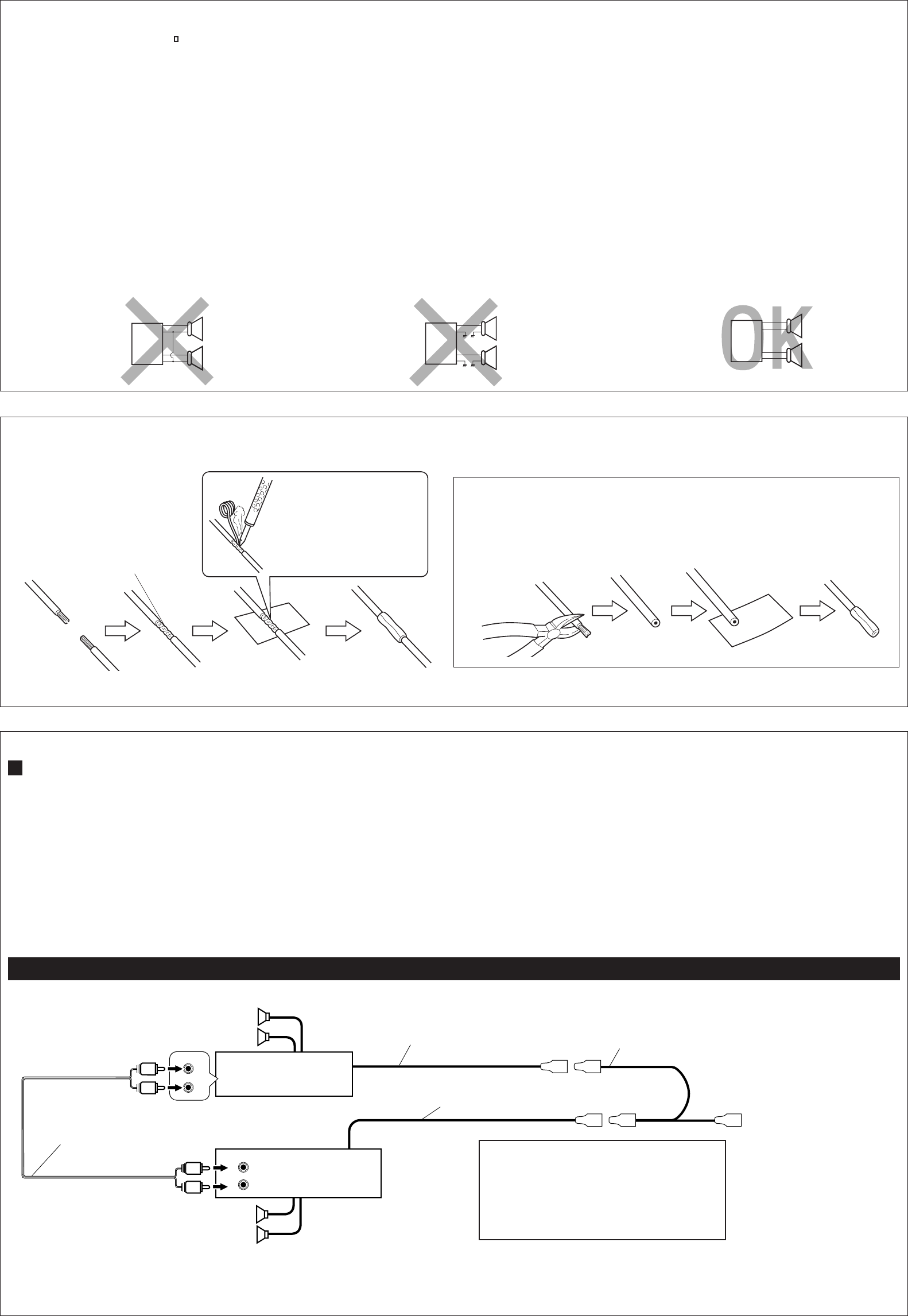
Amplifier / / uB« rC
PRECAUTIONS on power supply and speaker
connections:
•DO NOT connect the speaker leads of the power cord to the
car battery; otherwise, the unit will be seriously damaged.
• Connect the black lead (ground), yellow lead (to car battery,
constant 12V), and red lead (to an accessory terminal) correctly.
• BEFORE connecting the speaker leads of the power cord to
the speakers, check the speaker wiring in your car.
– If the speaker wiring in your car is as illustrated in Fig. 1
and Fig. 2 below, DO NOT connect the unit using that original
speaker wiring. If you do, the unit will be seriously damaged.
Redo the speaker wiring so that you can connect the unit to
the speakers as illustrated in Fig. 3.
– If the speaker wiring in your car is as illustrated in Fig. 3,
you can connect the unit using the original speaker wiring in
your car.
– If you are not sure of the speaker wiring of your car, consult
your car dealer.
Fig. 1 Fig. 2 Fig. 3
W??O?zU?Ðd?N?J?« W?U?D?« b?¹Ëe?ð ‰u?Š U?N?O?³?M?ðW??O?zU?Ðd?N?J?« W?U?D?« b?¹Ëe?ð ‰u?Š U?N?O?³?M?ð
W??O?zU?Ðd?N?J?« W?U?D?« b?¹Ëe?ð ‰u?Š U?N?O?³?M?ðW??O?zU?Ðd?N?J?« W?U?D?« b?¹Ëe?ð ‰u?Š U?N?O?³?M?ð
W??O?zU?Ðd?N?J?« W?U?D?« b?¹Ëe?ð ‰u?Š U?N?O?³?M?ð
∫UŽUL« qOuðË∫UŽUL« qOuðË
∫UŽUL« qOuðË∫UŽUL« qOuðË
∫UŽUL« qOuðË
•
ôô
ôô
ô ðuÒq? «Ýö„ ðe˹b ÞU?W «LU?ŽU l ÐDU?—¹W «OU?—…¨ ôÊ –p ¹RœÍ «v ŠBu‰ {d— KLUŽUÆ
•«Ëq «?Kp? «ôÝuœ ®«ô—{w?©¨ Ë«K?p «ôH?d ®l? ÐDU?—¹W «OU—…¨ ŁUÐX ≤± uX©¨ Ë«Kp «ôŠLd ®l «Dd· «ô{Uw© ÐAJq ×O`Æ
•³?q? ðu?O?q? «Ýö„ ðe?˹b? ÞU?W? «?L?U?ŽU? l? «?LU?ŽU?¨ «×h ý³JW «Ýö„ «LUŽU œ«šq ÝOU—ðpÆ ≠
««
««
«
––
––
–
««
««
«
U?U?
U?U?
U?
½½
½½
½
X?X?
X?X?
X?
ýý
ýý
ý
³?³?
³?³?
³?
J?J?
J?J?
J?
W?W?
W?W?
W?
««
««
«
ÝÝ
ÝÝ
Ý
ö?ö?
ö?ö?
ö?
„„
„„
„
««
««
«
??
??
?
L?L?
L?L?
L?
U?U?
U?U?
U?
ŽŽ
ŽŽ
Ž
U?U?
U?U?
U?
œœ
œœ
œ
««
««
«
šš
šš
š
q?q?
q?q?
q?
ÝÝ
ÝÝ
Ý
O?O?
O?O?
O?
U?U?
U?U?
U?
——
——
—
ðð
ðð
ð
p?p?
p?p?
p?
LL
LL
L
U?U?
U?U?
U?
¼¼
¼¼
¼
w?w?
w?w?
w?
³³
³³
³
OO
OO
O
MM
MM
M
WW
WW
W
ww
ww
w
««
««
«
AA
AA
A
JJ
JJ
J
qq
qq
q
±±
±±
±
ËË
ËË
Ë
««
««
«
AA
AA
A
JJ
JJ
J
qq
qq
q
≤≤
≤≤
≤
««
««
«
**
**
*
uu
uu
u
łł
łł
ł
uu
uu
u
œœ
œœ
œ
……
……
…
ww
ww
w
««
««
«
ôô
ôô
ô
ÝÝ
ÝÝ
Ý
HH
HH
H
qq
qq
q
¨¨
¨¨
¨
ô ðuÒq «'NU“ Ðu?«ÝDW «Ý²b?«Â ý³JW «Ýö„ «?LUŽU «ôKO?WÆ «–« - ðuOq «'NU“ ÐNcÁ «Dd¹IW¨ ÝORœÍ –p «v ŠBu‰ {d—Æ «Žb ŽLq ý³JW «Ýö„ «LUŽU Ð×OY 1JMp ðuOq «'NU“ l «LUŽU LU ¼u ³OÒs w «AJq ≥Æ ≠
««
««
«
––
––
–
««
««
«
U?U?
U?U?
U?
½½
½½
½
X?X?
X?X?
X?
ýý
ýý
ý
³?³?
³?³?
³?
J?J?
J?J?
J?
W?W?
W?W?
W?
««
««
«
ÝÝ
ÝÝ
Ý
ö?ö?
ö?ö?
ö?
„„
„„
„
««
««
«
??
??
?
L?L?
L?L?
L?
U?U?
U?U?
U?
ŽŽ
ŽŽ
Ž
U?U?
U?U?
U?
œœ
œœ
œ
««
««
«
šš
šš
š
q?q?
q?q?
q?
ÝÝ
ÝÝ
Ý
O?O?
O?O?
O?
U?U?
U?U?
U?
——
——
—
ðð
ðð
ð
p?p?
p?p?
p?
LL
LL
L
U?U?
U?U?
U?
¼¼
¼¼
¼
w?w?
w?w?
w?
³³
³³
³
OO
OO
O
MM
MM
M
WW
WW
W
ww
ww
w
««
««
«
AA
AA
A
JJ
JJ
J
qq
qq
q
≥≥
≥≥
≥
¨¨
¨¨
¨
1JMp ðuOq «'NU“ Ðu«ÝDW «Ý²b«Â ý³JW «Ýö„ «LUŽU «ôKOW œ«šq ÝOU—ðpÆ ≠w?? ŠU??W? Žb?? F??d??²??p?? ÐA?³??J??W?? «Ýö??„ «??L?U??ŽU?? œ«šq?? ÝOU—ðp¨ «Ý²Ad «uOq «Ë –ËÍ «)³d… ÐNc« «)Bu’Æ
L
R+
-
+
-
+
-
+
-
L
R+
-
+
-
+
-
+
-
L
R+
-
+
-
+
-
+
-
INPUT
R
L
R
L
LINE OUT
REAR
L
R
L
R
L
R
Rear speakers
WOHK)« UŽUL«
Blue with white stripe
iOÐôUÐ jD<« ‚—“ô«
Front speakers
WOUô« UŽUL«
Remote lead
bFÐ sŽ rJײ« pKÝ
KD-S600/S550
JVC power amplifier
W—U u rCJVC
You can connect an amplifier and other equipment to upgrade
your car stereo system.
•Connect the remote lead (blue with white stripe) to the remote
lead of the other equipment so that it can be controlled through
this unit.
•For amplifier only:
–Connect this unit’s line-out terminals to the amplifier’s line-in
terminals.
– Disconnect the speakers from this unit, connect them
to the amplifier. Leave the speaker leads of this unit
unused. (Cover the terminals of the these unused leads
with insulating tape, as illustrated above.)
u¹dO²Ý “UNł ¡«œ« 5ײ dš« “UNłË u rC qOuð pMJ1
Æ…—UO«
¿p?K?Ý l? ©i?O?ÐôU?Ð j?D?<« ‚—“ô«® b?F?Ð s?Ž r?Jײ« pKÝ qË«
‰öš s “UN'UÐ rJײ« r²¹ YO×Ð dšô« “UN−K bFÐ sŽ rJײ«
Æ“UN'« «c¼ ¿∫uB« rC* jI
‡‡j)« ‡ qšœ ·«dÞ« l “UN'« «cN j)« ‡ Ãdš ·«dÞ« qË«
ÆuB« rC* ‡‡Æu?B« rC l rNKË« ¨“UN'« «c¼ s UŽUL« qB«
wDž® ƉULF²Ý« ÊËbÐ “UN'« «c¼ UŽULÝ „öÝ« „dð«
`{u u¼ UL ¨‰“UŽ j¹dAÐ WKLF²*« dOž „öÝô« Ác¼ ·«dÞ«
ÆvKŽô« w
Solder the core wires to
connect them securely.
`O× qJAÐ „öÝô« r(«
ÆqOu²« bFÐ rJ×Ë
Twist the core wires when connecting.
q³ `O× qJAÐ „öÝô« ÂdЫ
ÆqOu²«
Y-connector (not supplied with this unit)
uÒ qYËe dOž® Ò©“UN'« l œ
Signal cord (not supplied with this unit)
Ëe dOž® œdH pKÝÒ©“UN'« l œ tO³Mð∫ tO³Mð∫
tO³Mð∫ tO³Mð∫
tO³Mð∫CAUTION / /
•To prevent internal heat builtup inside this unit,
place this unit UNDER the other equipment.
•
uJð lM*uJð lM*
uJð lM*uJð lM*
uJð lM*
ÒÒÒÒÒ
“UN'« «c¼ l{ ¨“UN'« qš«œ WOKš«b« …—«d(« Ê“UN'« «c¼ l{ ¨“UN'« qš«œ WOKš«b« …—«d(« Ê
“UN'« «c¼ l{ ¨“UN'« qš«œ WOKš«b« …—«d(« Ê“UN'« «c¼ l{ ¨“UN'« qš«œ WOKš«b« …—«d(« Ê
“UN'« «c¼ l{ ¨“UN'« qš«œ WOKš«b« …—«d(« Ê
Ædšô« «bF*« X%Ædšô« «bF*« X%
Ædšô« «bF*« X%Ædšô« «bF*« X%
Ædšô« «bF*« X%
Connecting the leads / / „öÝô« qOuð„öÝô« qOuð
„öÝô« qOuð„öÝô« qOuð
„öÝô« qOuð
!"#$%&'()*
• !"#$%&'&()*+,-./0123456
• !"#$%&"' ! !"#$ !"
! 12V !"#$ !"#$%&'()
• !"#$%&%' !"()*+,-./01 !"
– !"#$%&'()*12 !"#$%&'
!"#$%&'()*+,-./#0-123
!"# 3 !"#$%&'()*+
– !"#$%&'()*3 !"#$%&'()
!"#$%
– !"#$ %&'()*+,-./ 0%&123
• !"#$%&'()*+,%-./012
!"#
!"#$%&'(
!"#$%&'()
!"
!"#$%&'(
!"#$%&'()* +,-./0123456
• ! !"# !"#$%&'()*+,-.
!"#$%&'(
• !"#$%
– !"#$%&'()"*$%+,-./
– !"#$%&'()*+,!-#$. !)/
!" !"#$%&'()*+,-.)%/0
!"
!"
JVC !"
! !"#$%
!"
!"#$
!"
Y !" !"#$%
!"#$%
• !"#$%&'()*+,"-./012
!
•
To automatic antenna if any
błË Ê« wJOðUuðËô« wz«uN« v«
•
CAUTION / / tO³MðtO³Mð
tO³MðtO³Mð
tO³Mð
•To prevent short-circuit, cover the terminals of the UNUSED leads with insulating
tape.
•
·«dÞ« vKŽ oôË ‰“UŽ j¹dý l{ ¨WOzUÐdNJ« ‡‡ dz«Ëb« w dOBI²« lM qł« s·«dÞ« vKŽ oôË ‰“UŽ j¹dý l{ ¨WOzUÐdNJ« ‡‡ dz«Ëb« w dOBI²« lM qł« s
·«dÞ« vKŽ oôË ‰“UŽ j¹dý l{ ¨WOzUÐdNJ« ‡‡ dz«Ëb« w dOBI²« lM qł« s·«dÞ« vKŽ oôË ‰“UŽ j¹dý l{ ¨WOzUÐdNJ« ‡‡ dz«Ëb« w dOBI²« lM qł« s
·«dÞ« vKŽ oôË ‰“UŽ j¹dý l{ ¨WOzUÐdNJ« ‡‡ dz«Ëb« w dOBI²« lM qł« s
WKLF²*« dOž „öÝô«WKLF²*« dOž „öÝô«
WKLF²*« dOž „öÝô«WKLF²*« dOž „öÝô«
WKLF²*« dOž „öÝô«Æ
B Connections Adding Other Equipment / / WOU{ô« Èdšô« …eNłô« qOuðWOU{ô« Èdšô« …eNłô« qOuð
WOU{ô« Èdšô« …eNłô« qOuðWOU{ô« Èdšô« …eNłô« qOuð
WOU{ô« Èdšô« …eNłô« qOuð
•
•
•
•
•
Install.KD-S600/S550[U]/2 02/15/2000, 2:20 PM4
