JVC KS F150 User Manual FSUN3096 T181
User Manual: JVC KS-F150 KS-F150 English, Simplified Chinese, Arabic, INSTALLATION MANUAL
Open the PDF directly: View PDF ![]() .
.
Page Count: 4
184 mm
53 mm
Multi
Music
Scan
SEL
7
1234
56
40W
X
4
/I /I
ATT
TT
CD-
CH
TUNER TAPE
KS-F150
Installation/Connection Manual
1
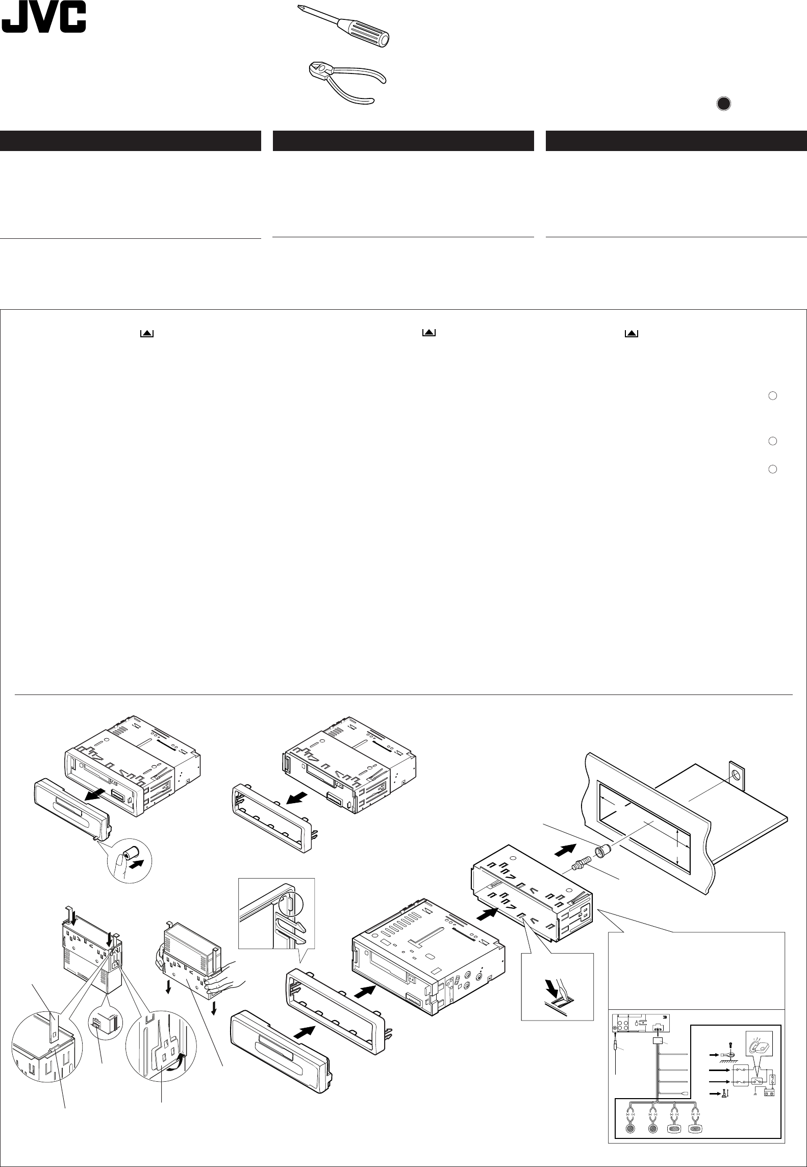
Before mounting: Press (Control Panel Release
button) to detach the control panel.
2
Remove the trim plate.
3
Remove the sleeve after disengaging the sleeve locks.
1Stand the unit.
Note: When you stand the unit, be careful not to damage
the fuse on the rear.
2Insert the 2 handles between the unit and the sleeve, as
illustrated, to disengage the sleeve locks.
3Remove the sleeve.
Note: Be sure to keep the handles for future use after
installing the unit.
4
Install the sleeve in the dashboard.
* After the sleeve is correctly installed in the dashboard,
bend the appropriate tabs to hold the sleeve firmly in place,
as illustrated.
5
Fix the mounting bolt to the rear of the unit’s body and place
the rubber cushion over the end of the bolt.
6
Do the required electrical connections explained on the back
of this instructions.
7
Slide the unit into the sleeve until it is locked.
8
Attach the trim plate.
9
Attach the control panel.
J
V
C
7
8
*
4
6
5
4
wÐdŽwÐdŽ
wÐdŽwÐdŽ
wÐdŽ
•
wzUÐdN —UOð WDÝ«uÐ qLFO “UN'« «c¼ rLbI dýU³ DC
ÆVUÝ i¹—Qð WOzUÐdN WLE½« ¨Xu ±≤
ðð
ðð
ð
dd
dd
d
OO
OO
O
VV
VV
V
««
««
«
''
''
'
NN
NN
N
UU
UU
U
““
““
“
®®
®®
®
œœ
œœ
œ
««
««
«
šš
šš
š
qq
qq
q
‡‡‡‡‡
ðð
ðð
ð
UU
UU
U
ÐÐ
ÐÐ
Ð
KK
KK
K
uu
uu
u««
««
«
OO
OO
O
UU
UU
U
——
——
—
……
……
…
©©
©©
©
•O³¹Òl ÆWOU¦*« VOd²« WI¹dÞ wU²« w×O{u²« rÝd« s
w?²?« …—U?O??« Ÿu?½ o?ÐU?D?ð ö?¹b?F?ð q?L?Ž p?O?KŽ V−¹ ¨p–
’uBÐ UuKF* WłUŠ Ë« «—UH²Ý« „UM¼ ÊU «–« ÆUNJK²9
W?O?ðu?B?« …e?N?łô« Ÿ“u? …—U?A?²?Ý« v?łd?¹ ¨VOd²« «Ëœ«
W—U «—UOKJVCÆ«Ëœô« …cN WŽ“u*« WdA« Ë«
±
³?³?
³?³?
³?
q??q??
q??q??
q??
ÐÐ
ÐÐ
Ð
b?b?
b?b?
b?
¡¡
¡¡
¡
««
««
«
²??²??
²??²??
²??
d?d?
d?d?
d?
O??O??
O??O??
O??
V?V?
V?V?
V?
∫∫
∫∫
∫ «{G??j? «d??“ ®“— %d?¹d? u??ŠW? «²×Jr© s «łq Bq uŠW «²×JrÆ ≤≤
≤≤
≤«½eŸ uŠW «e¹MWÆ ≥≥
≥≥
≥
«½eŸ «NOJq «u«w ÐFb Bq ¦³²U «NOJq «u«wÆ
±nË« «'NU“ ÐAJq ŽLuœÍÆ
öö
öö
ö
ŠŠ
ŠŠ
Š
E?E?
E?E?
E?
WW
WW
W
∫∫
∫∫
∫ ŽM?b ðu?On «'N?U“¨ ðQ?b s Žb? ðCd?— «Ë «ðö· «HOu“ «*ułuœ w «'NW «)KHOW s «'NU“Æ
≤O³ u¼ UL ¨w«u« qJON«Ë “UN'« 5Ð 5²U*« qšœÒs qJA« w¨ HBq ¦³?²U «NOJq «u«wÆ
≥«½eŸ «NOJq «u«wÆ
öö
öö
ö
ŠŠ
ŠŠ
Š
EE
EE
E
WW
WW
W
∫∫
∫∫
∫ ¹dłw «;UEW ŽKv «*UU s «łq «ôݲFLU‰ ôŠIU ÐFb ðdOV «'NU“Æ ¥¥
¥¥
¥—V «NOJq «u«w œ«šq ðUÐKu «OU—…Æ
*ÐFb ðdOV «NOJq «u«w KOU œ«šq ðUÐKu «OU—… ÐAJq ×?O?`¨ «ŁM?w? «_?M?W? ÐAJ?q? M?U?ÝV ²?¦?³?O?X? «NO?J?q? «u«w? ÐAJ?q ×?Jr? w «*JU?Ê «B×?O`?¨ LU? ¼u O?³Òs w «AJqÆ µµ
µµ
µŁ³ÒX LU— «²dOV ÐU'NW «)KHOW s ¼OJq «'NU“ ËÐFb –p {l «(Au… «*DUÞOW u‚ ½NU¹W «*LU—Æ ∂∂
∂∂
∂
«ŽLq «²uOö «JNdÐUzOW «*DKuÐW LU ¼u AdËÕ nKš ¼cÁ «²FKOLUÆ ∑∑
∑∑
∑«œšq «'NU“ œ«šq «NOJq «u«w Š²v ¹¦³X ÐAJq ×O`Æ ∏∏
∏∏
∏
—ÒV uŠW «e¹MWÆ ππ
ππ
π—ÒV uŠW «²×JrÆ
O²O²
O²O²
O²
ÒÒÒÒÒ
ØVOd²« ULOKFð VØVOd²« ULOKFð V
ØVOd²« ULOKFð VØVOd²« ULOKFð V
ØVOd²« ULOKFð V
qOu²«qOu²«
qOu²«qOu²«
qOu²«
9
Dashboard
…—UO« uKÐUð
Mounting bolt
VOd²« —UL
Sleeve
w«u« qJON«
Trim plate
WM¹e« WŠu
See the back page for electrical
connections.
qł« s WOHK)« W×HB« dE½«
ÆWOzUÐdNJ« öOu²«
0100HISFLEJES
EN, CH, AR
FSUN3096-T181
[U]
Multi
Music
Scan
12
10
3
10
1
23
1
2
3
5
4
WOÞUD*« …uA(«
Rubber cushion
Sleeve
w«u« qJON«
Lock plate
XO³¦²« W×OH
Fuse
“uOH«
Slot
oýÒdOG
Handle
WU*«
ENGLISH
•This unit is designed to operate on 12 volts DC, NEGATIVE
ground electrical systems.
INSTALLATION (IN-DASH
MOUNTING)
•The following illustration shows a typical installation. However,
you should make adjustments corresponding to your specific
car. If you have any questions or require information regarding
installation kits, consult your JVC car audio dealer or a company
supplying kits.
!"#$
• !"#$% 12V !"#$%&'(
!
!"#$%
!
!
!"
!
!"#$%&' ()*+,-./0123452
!"#$%&'()*+,-%./0 123.45
!"#$%&JVC !"#$%&'()*+,-
•
!"#$%&'()*
!"
1
!" !"#$%& !"#$
2
!"#
3
!"#$%&'()&*+
1 !"#
!"#$%&'()*+,-./01
2 !"#$%&'(%)*+,-./0123
!"
3 !"#$
!"#$%&'()*+,#-./0123
4
!"#$%&'()
* !"#$%&'()*+,-./01-23!"45
!"#$%&'()*+
5
!"#$%&&'()*+,-./0$ !"1
6
!"#$%&'()%*+,-./01
7
!"#$ %&'( !"
8
!"
9
!"#$
•
•
Install.KS-F150[U]/1 02/15/2000, 12:52 PM1
3
2
1
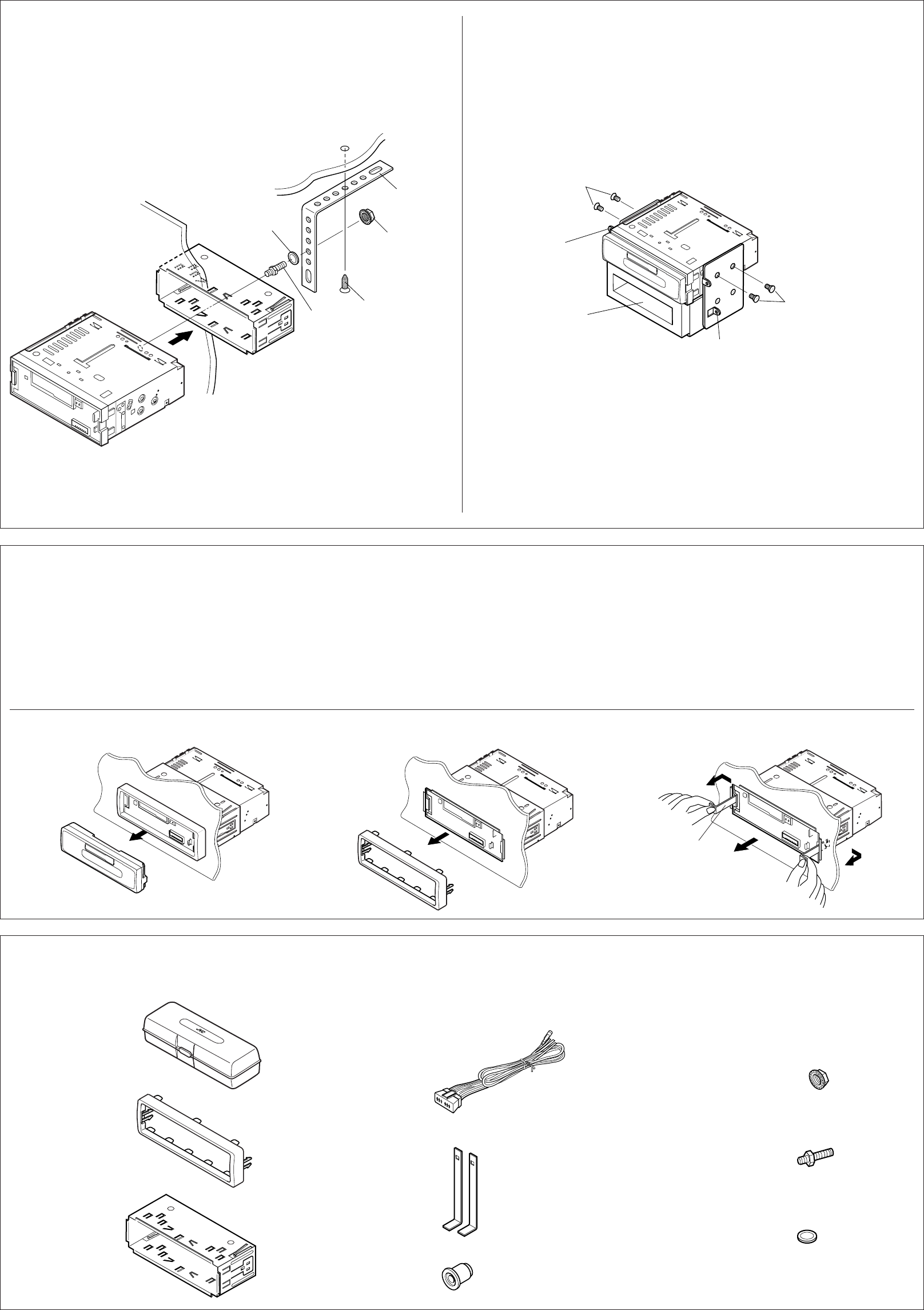
Removing the unit
• Before removing the unit, release the rear section.
1
Remove the control panel.
2
Remove the trim plate.
3
Insert the 2 handles into the slots, as shown. Then, while gently
pulling the handles away from each other, slide out the unit.
(Be sure to keep the handles after installing it.)
• When using the optional stay
Dashboard
Fire wall
Mounting bolt
VOd²« —UL
Sleeve
Screw (option)
©wU{«® wždÐ
Parts list for installation and connection
The following parts are provided with this unit.
After checking them, please set them correctly.
Stay (option)
Lock nut
XO³¦²« WuL
Multi
Music
Scan
SEL SSM
7
123456
40W
X
4
/I
ATT
CD-
CH
TUNER TAPE
s W¹UL(« —«bł
o¹d(«
…—UO« uKÐUð
w«u« qJON«
…—UO« uKÐUð s “UN'« Ÿe½…—UO« uKÐUð s “UN'« Ÿe½
…—UO« uKÐUð s “UN'« Ÿe½…—UO« uKÐUð s “UN'« Ÿe½
…—UO« uKÐUð s “UN'« Ÿe½
•ÆwHK)« ¡e'« —dŠ ¨“UN'« Ÿe½ q³
±±
±±
±ÆrJײ« WŠu Ÿe½«
≤≤
≤≤
≤ÆWM¹e« WŠu Ÿe½«
≥≥
≥≥
≥bFÐ ÆqJA« w 5³ u¼ UL ¨‚uIA« qš«œ 5²U*« qšœ«
¨Èdšô« sŽ …bŠ«u« «bOFÐ WUDKÐ 5²U*« V×Ý ¡UMŁ« ¨p–
Æ×U)« v« “UN'« V×Ý«
©“UN'« VOdð bFÐ 5²U*UÐ pþUH²Š« s bQ𮩓UN'« VOdð bFÐ 5²U*UÐ pþUH²Š« s bQð®
©“UN'« VOdð bFÐ 5²U*UÐ pþUH²Š« s bQ𮩓UN'« VOdð bFÐ 5²U*UÐ pþUH²Š« s bQð®
©“UN'« VOdð bFÐ 5²U*UÐ pþUH²Š« s bQð®
qOu²«Ë VOd²« ¡«eł« WLzUqOu²«Ë VOd²« ¡«eł« WLzU
qOu²«Ë VOd²« ¡«eł« WLzUqOu²«Ë VOd²« ¡«eł« WLzU
qOu²«Ë VOd²« ¡«eł« WLzU
Æ“UN'« l …œËe WOU²« ¡«ełô«
Æ`O× qJAÐ rN³Odð vłd¹ ¨¡«ełô« Ác¼ h× bFÐ
•
XO³¦²K wU{« bM «b²Ý« bMŽXO³¦²K wU{« bM «b²Ý« bMŽ
XO³¦²K wU{« bM «b²Ý« bMŽXO³¦²K wU{« bM «b²Ý« bMŽ
XO³¦²K wU{« bM «b²Ý« bMŽ
ŠKIW «ŠJUÂ «²uOq
XO³¦ð bM
©wU{«®
Rubber cushion
WOÞUD*« …uA(«
Sleeve
w«u« qJON«
Hard case
VK ‚ËbM
Handles
•When installing the unit without using the sleeve
In a Toyota for example, first remove the car radio and install the unit in its place.
•
w«u« qJON« «b²Ý« ÊËbÐ “UN'« Vdð UbMŽw«u« qJON« «b²Ý« ÊËbÐ “UN'« Vdð UbMŽ
w«u« qJON« «b²Ý« ÊËbÐ “UN'« Vdð UbMŽw«u« qJON« «b²Ý« ÊËbÐ “UN'« Vdð UbMŽ
w«u« qJON« «b²Ý« ÊËbÐ “UN'« Vdð UbMŽ
Washer
UU*«
Trim plate
WM¹e« WŠu
Washer (ø5)
ÂUJŠ« WIKŠ
©µ dD® qOu²«
Handle
WU*«
Power cord
WOzUÐdNJ« WUD« pKÝ Lock nut (M5)
® XO³¦²« WuLM5©
Mounting bolt (M5 x 20 mm)
® VOd²« —ULM5©rK ≤∞ ™
• !"#
!"
!
!"
!
!
• !"#$%&'($
!"#$%&'()*+,6mm !"#$%&' !"()*+,-#
!TOYOTA !"#$%&'()*+,-.)/012&3456
!(M5 x 6 mm)* * !"#$
*
*
!(M5 x 6 mm)*
!
• !"#$%&!"'()*+,-.(/012
1
!"#$
2
!"#
3
!"#$%&'()*+,-."/01234$5
!"#$%&'() *+
!"#$%&'()*+,-.
!"
!"#$%&'(
!"#$%&'()
!"#$%&'()*
!
!"#$%&
!"
!"
! (M5)
(ø5)
! (M5 x 20 mm)
Note: When installing the unit on the mounting bracket, make sure to use the 6 mm-long screws. If
longer screws are used, they could damage the unit.
∫WEŠö∫WEŠö
∫WEŠö∫WEŠö
∫WEŠöWUŠ w ÆrK ∂ ‰uÞ wž«dÐ Âb²Ý« s bQð ¨XO³¦²« WOH² vKŽ “UN'« VOdð bMŽ
«b²Ý«wž«dÐÆ“UN'« —d{ Ë« nKð V³¹ Ê« sJ1 p– ÊU ¨rK ∂ s ‰uÞ«
ŽKv ݳOq «*¦U‰¨ w ÝOU—« ½uŸ ðu¹uðU¨ «½eŸ —«œ¹u «OU—… «Ëô ÐFb –p —ÒV «'NU“ w JU½tÆ
Multi
Multi
Music
Music
Scan
Scan
SEL
SELSSM
SSM
7
1234 5 6
40W40W
X
4
/I
/I
ATT
TT
CD-
CD-
CH
CH
TUNER
TUNER TAPE
* Not included with this unit.
Bracket*
Bracket*
Flat type screws (M5 x 6 mm)*
® …bŽUI« W¹u² wž«dÐM5©rK ∂ ™ *
VOł
XO³¦²« WOH²
*
Pocket
WOH²
XO³¦²«
*
*
Ëe dOžÒÆ“UN'« «c¼ l œ
Flat type screws (M5 x 6 mm)*
® …bŽUI« W¹u² wž«dÐM5©rK ∂ ™ *
••
•
Install.KS-F150[U]/1 02/15/2000, 12:54 PM2
10
2
1
3
3
4
5
2
1
ENGLISH
ELECTRICAL CONNECTIONS
To prevent short circuits, we recommend that you disconnect the
battery’s negative terminal and make all electrical connections
before installing the unit. If you are not sure how to install this unit
correctly, have it installed by a qualified technician.
Note:
This unit is designed to operate on 12 volts DC, NEGATIVE
ground electrical systems. If your vehicle does not have this
system, a voltage inverter is required, which can be purchased at
JVC car audio dealers.
• Replace the fuse with one of the specified rating. If the fuse
blows frequently, consult your JVC car audio dealer.
• If noise is a problem...
This unit incorporates a noise filter in the power circuit. However,
with some vehicles, clicking or other unwanted noise may occur.
If this happens, connect the unit’s rear ground terminal (See
connection diagram below.) to the car’s chassis using shorter
and thicker cords, such as copper braiding or gauge wire. If noise
still persists, consult your JVC car audio dealer.
• Maximum input of the speakers should be more than 40 watts at
the rear and 40 watts at the front, with an impedance of 4 to 8
ohms.
•Be sure to ground this unit to the car’s chassis.
• The heat sink becomes very hot after use. Be careful not to
touch it when removing this unit.
wÐdŽwÐdŽ
wÐdŽwÐdŽ
wÐdŽ
WOzUÐdNJ« öOu²«WOzUÐdNJ« öOu²«
WOzUÐdNJ« öOu²«WOzUÐdNJ« öOu²«
WOzUÐdNJ« öOu²«
·dÞ qBHÐ wu½ ¨WOzUÐdNJ« dz«Ëb« w dOBIð ÀËbŠ lM*
VOdð q³ WOzUÐdNJ« öOu²« qLŽ rŁ VU« W¹—UD³«
q?J?A?Ð “U?N?'« V?O?d?ð W?O?H?O?J?Ð p?²?d?F? Âb?Ž WUŠ w Æ“UN'«
q¼RË h² hA “UN'« VOdð WOKLŽ „dð vłd¹ ¨`O×
Æ…eNłô« Ác¼ q¦ VOd²
∫WEŠö∫WEŠö
∫WEŠö∫WEŠö
∫WEŠö
—UOð WDÝ«uÐ qLFO “UN'« «c¼ rL bI
dýU³ wzUÐdN dýU³ wzUÐdN
dýU³ wzUÐdN dýU³ wzUÐdN
dýU³ wzUÐdNDC
VUÝ i¹—Qð WOzUÐdN WLE½« ¨Xu ±≤VUÝ i¹—Qð WOzUÐdN WLE½« ¨Xu ±≤
VUÝ i¹—Qð WOzUÐdN WLE½« ¨Xu ±≤VUÝ i¹—Qð WOzUÐdN WLE½« ¨Xu ±≤
VUÝ i¹—Qð WOzUÐdN WLE½« ¨Xu ±≤œułË ÂbŽ WUŠ w Æ
¨ÃU?²?u? ‰u?× Â«b²Ý« V−¹ ¨pð—UOÝ w ÂUEM« «c¼ q¦
W—U «—UOK WOðuB« …eNłô« ¡öË s ‰u;« «c¼ ¡«dý sJ1
JVCÆ•«–« ÆW?u?u?*« U?ÝU?O?I?« f?H½ qL×¹ dšPÐ “uOH« ‰b³²Ý«
WOðuB« …eNłô« ¡öË …—UA²Ý« vłd¹ ¨“uOH« ‚«d²Š« —dJð
W—U «—UOKJVCÆ•ÆÆÆWKJA*« u¼ ZO−C« ÊU «–«
W???U???D???« …d???z«œ q???š«œ Z???O???−???{ d???²???K??? “U??N??'« «c??¼ Âb????²????¹
Ÿu½ Àb×¹ Ê« sJ1 ¨«—UO« iFÐ w ¨p– l ÆWOzUÐdNJ«
q¦ ÀËbŠ WUŠ w Æ»užd*« dOž ZO−C« Ë« WIDID« s
i?¹—Q²« ·dÞ qË« ¨p–
“U?N?'« WOHKš w œułu*«“U?N?'« WOHKš w œułu*«
“U?N?'« WOHKš w œułu*«“U?N?'« WOHKš w œułu*«
“U?N?'« WOHKš w œułu*«d?E½«®
W??D??Ý«u??Ð …—U??O????« q??J??O??¼ l?? ©q??H??Ýô« w?? q?O?u?²?« r?Ý—
‰Ëb?:« ”U?×?M?« p?K?Ý q?¦ ¨pLÝ«Ë dB« „öÝ« «b²Ý«
¨ZO−C« Ë« WIDID« nuð ÂbŽ WUŠ w ÆwÝUOI pKÝ Ë«
W—U «—UOK WOðuB« …eNłô« ¡öË …—UA²Ý« vłd¹JVCÆ•¥∞ s? d?¦?« U?ŽU?L??« q?šb? v?B?ô« b?(« ÊuJ¹ Ê« V−¹
l? ¨W?O?U?ô« U?ŽU?L??K? ◊«Ë ¥∞ Ë W?O?H?K?)« UŽULK ◊«Ë
5Ð WF½U2
ÆÂË« ∏ v« ¥ÆÂË« ∏ v« ¥
ÆÂË« ∏ v« ¥ÆÂË« ∏ v« ¥
ÆÂË« ∏ v« ¥ •
Æ…—UO« qJO¼ l “UN'« i¹—Qð s bQðÆ…—UO« qJO¼ l “UN'« i¹—Qð s bQð
Æ…—UO« qJO¼ l “UN'« i¹—Qð s bQðÆ…—UO« qJO¼ l “UN'« i¹—Qð s bQð
Æ…—UO« qJO¼ l “UN'« i¹—Qð s bQð •bQð Æ«b²Ýô« bFÐ «bł WMšUÝ …—«d(« iHš W×OH `³Bð
Æ“UN'« Ÿe½ bMŽ UN²ö ÂbŽ s
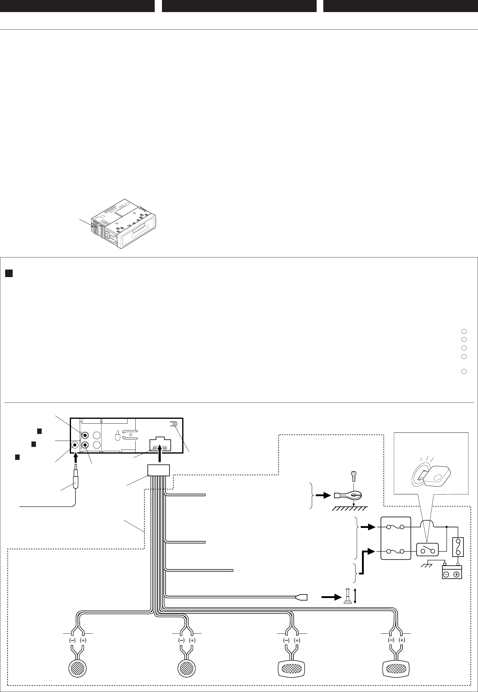
Before connecting: Check the wiring in the vehicle carefully.
Incorrect connection may cause serious damage to this unit.
1
Connect the colored leads of the power cord to the car battery,
speakers and automatic antenna (if any) in the following
sequence.
1Black: ground
2Yellow: to car battery (constant 12V)
3Red: to an accessory terminal
4Blue with white stripe: to automatic antenna (200mA
max.)
5Others: to speakers
2
Connect the antenna cord.
3
Finally connect the wiring harness to the unit.
∫q?O?u?²?U?Ð ¡b?³« q³ ∫q?O?u?²?U?Ð ¡b?³« q³
∫q?O?u?²?U?Ð ¡b?³« q³ ∫q?O?u?²?U?Ð ¡b?³« q³
∫q?O?u?²?U?Ð ¡b?³« q³…—U?O??« w? „ö?Ýô« W?J?³ý s bQð
Ê« s?J?1 Æ“U?N?'« q?O?u?ð W?OKLŽ w QDš Àb×¹ ô v²Š WbÐ
Æ“UN−K wIOIŠ qDŽ ‰uBŠ v« ¡vÞU)« qOu²« V³¹
±±
±±
±
l? W?O?zUÐdNJ« WUD« b¹Ëeð pK W½uK*« „öÝô« qË«
Ê«® w?J?O?ðU?u?ðËô« w?z«uN«Ë UŽUL« ¨…—UO« W¹—UDÐ
ÆwU²« qK²« VŠ ©błË
±©…—UO« qJO¼ l® ÷—ô« l ∫œuÝô« pK«
≤©Xu ±≤ XÐUŁ® …—UO« W¹—UDÐ l ∫dHô« pK«
≥wU{ô« ·dD« l ∫dLŠô« pK«
¥wJOðUuðËô« wz«uN« l ∫iOÐôUÐ jD<« ‚—“ô« pK«
©dO³« wKKO ≤∞∞ vBô« b(«®
µUŽUL« l ∫Èdšô« „öÝô« ≤≤
≤≤
≤
Æwz«uN« pKÝ qË« ≥≥
≥≥
≥Æ“U?N'« l „öÝô« qUŠ qË« ¨«dOš«
Heat sink
iHš W×OH
…—«d(«
*
*
Not included with this unit.
Ëe dOžÒÆ“UN'« «c¼ l œ
To automatic antenna if any
błË Ê« wJOðUuðËô« wz«uN« v«
Red
dLŠ√
Blue with white stripe
iOÐôUÐ jD ‚—“« pKÝ
Ignition switch
‰UF²ýô« ÕU²H
*
*1: Before checking the operation of this unit prior to
installation, this lead must be connected, otherwise
power cannot be turned on.
¿
±∫V−¹ ¨VOd²« q³ “UN'« «c¼ qOGAð h× q³
ÊËbÐ “UN'« qOGAð sJ1 ô YOŠ ¨pK« «c¼ qOuð
ÆpK« qOuð
Purple
w½«uł—«
To metallic body or chassis of the car
…—UO« qJO¼ Ë« w½bF*« r'« v«
w½bF*«
Antenna terminal
wz«uN« ·dÞ Black
œuÝ√
Fuse block
“uOH« WŽuL−
Green
dCš«
Purple with black stripe
œuÝôUÐ jD w½«uł—«
Green with black stripe
œuÝôUÐ jD dCš√
White
iOÐ√
White with black stripe
jD iOЫ pKÝ
œuÝôUÐ
Line out
(see diagram B )
j)« Ãdš
jD<« dE½«® jD<« dE½«®
jD<« dE½«® jD<« dE½«®
jD<« dE½«®B
© ©
© ©
©
Right
«OLMv
!"#$%&'()*+,#-./0123#4567/
!"#$%&'()*$+,)-./012345678
!"#$
!"#$%12V !"#$%&' !"#$%&
!"#$%&'( )*+,$-./JVC !"#
!"
• !"#$%&'()* !+,- !./0123
JVC !"#$%&'
• !"#$
!"#$%&'()*+,-./0 12345067
!"#$%&'()*+,-./012345678
!"#$%&'()*%+,-./&012 !"
!"#$%&'( !"#$%&'()*+ JVC
!"#$%&
• !"#$%&'()*%+ 40 !"#$%&'(
40 !"#$ 4 – 8
• !"#$%&'()
• !"#$%&'(%)*+#,-./#01234
!"
!"#$
! !"#$%&'()*+%,&-./01234
1
!"#$%&'()*+,-.%/012/34
!"#$%&' !"#
1 !"
2 !"#$%& 12V
3 !"#$%&'()*+,-
4 !"#$%&'()*+,- 200
5 !"#$%
2
!" #$%&'
3
!"#$%&'&()*+,
!"#$ !"#$
!"#$%
!"#$%&'
!"#$%&'()*+ !"#$,
!"#$ !"#$%&'
!"#$%&'()*
!
!"
!"#$%
! !
!"#$
! !
!"#$
! !
!
!
!
!
!
10A !"#$%
*1: !"#$%&'()*+,-.$/01234
!"#$%&'(
*1
!"#$
! !
A Typical Connections / / WOł–uLM« öOu²«WOł–uLM« öOu²«
WOł–uLM« öOu²«WOł–uLM« öOu²«
WOł–uLM« öOu²«
B
To antenna
wz«uN« v«
Rear ground terminal
wHK)« i¹—Q²« ·dÞ
To a live terminal in the fuse block connecting
to the car battery (bypassing the ignition switch)
«v «Dd· «(w w −LuŽW «HOu“ «*uuW l «³DU—¹W ®dË—« 0H²UÕ «ôý²FU‰©
Gray with black stripe
œuÝôUÐ jD ÍœU—
Right speaker (front)
©WOUô«® vMLO« WŽUL«
Left speaker (rear)
©WOHK)«® ÈdO« WŽUL«
Right speaker (rear)
«LUŽW «OLMv ®«)KHOW©
Left speaker (front)
©WOUô«® ÈdO« WŽUL«
Yellow*1
dH√
¿
±
•
•
•
•
•
10A fuse
Ou“ ∞± «³Od
Gray
ÍœU—
To an accessory terminal in the fuse block
“uOH« WŽuL− w wU{ô« ·dD« v«
Left
—U¹
Install.KS-F150[U]/1 02/15/2000, 12:57 PM3
PRECAUTIONS on power supply and speaker
connections:
• DO NOT connect the speaker leads of the power cord to the
car battery; otherwise, the unit will be seriously damaged.
• Connect the black lead (ground), yellow lead (to car battery,
constant 12V), and red lead (to an accessory terminal) correctly.
• BEFORE connecting the speaker leads of the power cord to
the speakers, check the speaker wiring in your car.
– If the speaker wiring in your car is as illustrated in Fig. 1
and Fig. 2 below, DO NOT connect the unit using that original
speaker wiring. If you do, the unit will be seriously damaged.
Redo the speaker wiring so that you can connect the unit to
the speakers as illustrated in Fig. 3.
– If the speaker wiring in your car is as illustrated in Fig. 3,
you can connect the unit using the original speaker wiring in
your car.
– If you are not sure of the speaker wiring of your car, consult
your car dealer.
W??O?zU?Ðd?N?J?« W?U?D?« b?¹Ëe?ð ‰u?Š U?N?O?³?M?ðW??O?zU?Ðd?N?J?« W?U?D?« b?¹Ëe?ð ‰u?Š U?N?O?³?M?ð
W??O?zU?Ðd?N?J?« W?U?D?« b?¹Ëe?ð ‰u?Š U?N?O?³?M?ðW??O?zU?Ðd?N?J?« W?U?D?« b?¹Ëe?ð ‰u?Š U?N?O?³?M?ð
W??O?zU?Ðd?N?J?« W?U?D?« b?¹Ëe?ð ‰u?Š U?N?O?³?M?ð
∫UŽUL« qOuðË∫UŽUL« qOuðË
∫UŽUL« qOuðË∫UŽUL« qOuðË
∫UŽUL« qOuðË
•uð ôÒ¨…—UO« W¹—UDÐ l UŽUL« WUÞ b¹Ëeð „öÝ« q
ÆUŽULK —d{ ‰uBŠ v« ÍœR¹ p– Êô
•W¹—UDÐ l® dHô« pK«Ë ¨©w{—ô«® œuÝô« pK« qË«
·d??D??« l??® d??L??Šô« p??K????«Ë ¨©X??u?? ±≤ X??ÐU?Ł ¨…—U?O??«
Æ`O× qJAÐ ©wU{ô«
•¨U?ŽU?L??« l? U?ŽUL« WUÞ b¹Ëeð „öÝ« qOuð q³
Æpð—UOÝ qš«œ UŽUL« „öÝ« WJ³ý h׫
≠
w?¼ U?L? p?ð—U?OÝ qš«œ UŽUL« „öÝ« WJ³ý X½U «–«w?¼ U?L? p?ð—U?OÝ qš«œ UŽUL« „öÝ« WJ³ý X½U «–«
w?¼ U?L? p?ð—U?OÝ qš«œ UŽUL« „öÝ« WJ³ý X½U «–«w?¼ U?L? p?ð—U?OÝ qš«œ UŽUL« „öÝ« WJ³ý X½U «–«
w?¼ U?L? p?ð—U?OÝ qš«œ UŽUL« „öÝ« WJ³ý X½U «–«
¨qHÝô« w …œułu*« ≤ qJA«Ë ± qJA« w WMO³ ¨qHÝô« w …œułu*« ≤ qJA«Ë ± qJA« w WMO³
¨qHÝô« w …œułu*« ≤ qJA«Ë ± qJA« w WMO³ ¨qHÝô« w …œułu*« ≤ qJA«Ë ± qJA« w WMO³
¨qHÝô« w …œułu*« ≤ qJA«Ë ± qJA« w WMO³uð ôÒq
ÆWOKô« UŽUL« „öÝ« WJ³ý «b²Ý« WDÝ«uÐ “UN'«
‰uBŠ v« p– ÍœROÝ ¨WI¹dD« ÁcNÐ “UN'« qOuð - «–«
p??M??J??1 Y?O?×?Ð U?ŽU?L??« „ö?Ý« W?J?³?ý q?L?Ž b?Ž« Æ—d?{
O³ u¼ UL UŽUL« l “UN'« qOuðÒÆ≥ qJA« w s ≠
w?¼ U?L? p?ð—U?OÝ qš«œ UŽUL« „öÝ« WJ³ý X½U «–«w?¼ U?L? p?ð—U?OÝ qš«œ UŽUL« „öÝ« WJ³ý X½U «–«
w?¼ U?L? p?ð—U?OÝ qš«œ UŽUL« „öÝ« WJ³ý X½U «–«w?¼ U?L? p?ð—U?OÝ qš«œ UŽUL« „öÝ« WJ³ý X½U «–«
w?¼ U?L? p?ð—U?OÝ qš«œ UŽUL« „öÝ« WJ³ý X½U «–«
¨≥ qJA« w WMO³ ¨≥ qJA« w WMO³
¨≥ qJA« w WMO³ ¨≥ qJA« w WMO³
¨≥ qJA« w WMO³Â«b²Ý« WDÝ«uÐ “UN'« qOuð pMJ1
Æpð—UOÝ qš«œ WOKô« UŽUL« „öÝ« WJ³ý ≠q??š«œ U??ŽU??L???« „ö?Ý« W?J?³?A?Ð p?²?d?F? Âb?Ž W?U?Š w?
Æ’uB)« «cNÐ …d³)« ÍË– Ë« qOu« dA²Ý« ¨pð—UOÝ
TROUBLESHOOTING
•The fuse blows.
* Are the red and black leads connected correctly?
•Power cannot be turned on.
* Is the yellow lead connected?
•No sound from the speakers.
* Is the speaker output lead short-circuited?
•Sound is distorted.
* Is the speaker output lead grounded?
* Are the “–” terminals of L and R speakers grounded in common?
•Unit becomes hot.
* Is the speaker output lead grounded?
* Are the “–” terminals of L and R speakers grounded in common?
Õöô«Ë ‰UDŽô« sŽ Y׳«Õöô«Ë ‰UDŽô« sŽ Y׳«
Õöô«Ë ‰UDŽô« sŽ Y׳«Õöô«Ë ‰UDŽô« sŽ Y׳«
Õöô«Ë ‰UDŽô« sŽ Y׳«
•
Æ“uOH« ‚d²×¹Æ“uOH« ‚d²×¹
Æ“uOH« ‚d²×¹Æ“uOH« ‚d²×¹
Æ“uOH« ‚d²×¹ *ø`O× qJAÐ Wuu œuÝô«Ë dLŠô« pK« q¼
•
ÆWOzUÐdNJ« WUD« qOuð sJ1 ôÆWOzUÐdNJ« WUD« qOuð sJ1 ô
ÆWOzUÐdNJ« WUD« qOuð sJ1 ôÆWOzUÐdNJ« WUD« qOuð sJ1 ô
ÆWOzUÐdNJ« WUD« qOuð sJ1 ô *øôuu dHô« pK« q¼
•
ÆUŽUL« s u —bB¹ ôÆUŽUL« s u —bB¹ ô
ÆUŽUL« s u —bB¹ ôÆUŽUL« s u —bB¹ ô
ÆUŽUL« s u —bB¹ ô *øWŽUL« Ãdš pKÝ …dz«œ w dOBIð pUM¼ q¼
•
ÆÁuA uB«ÆÁuA uB«
ÆÁuA uB«ÆÁuA uB«
ÆÁuA uB« *ø÷—ôUÐ ôuu WŽUL« Ãdš pKÝ q¼ * Èd??O?« W?ŽU?L??K? å≠ò W?³?U??« ·«d?Þô« q¼L v?M?L?O?«Ë R
øiFÐ l ÷—ôUÐ Wuu
•
Æ“UN'« s¹Æ“UN'« s¹
Æ“UN'« s¹Æ“UN'« s¹
Æ“UN'« s¹ *ø÷—ôUÐ ôuu WŽUL« Ãdš pKÝ q¼ * Èd??O?« W?ŽU?L??K? å≠ò W?³?U??« ·«d?Þô« q¼L v?M?L?O?«Ë R
øiFÐ l ÷—ôUÐ Wuu
L
R+
-
+
-
+
-
+
-
Fig. 3
L
R+
-
+
-
+
-
+
-
Fig. 2
L
R+
-
+
-
+
-
+
-
Fig. 1
Connecting the leads / / „öÝô« qOuð„öÝô« qOuð
„öÝô« qOuð„öÝô« qOuð
„öÝô« qOuð
Solder the core wires to
connect them securely.
`??O??×?? q??J??A??Ð „ö??Ýô« r??(«
ÆqOu²« bFÐ rJ×Ë
Twist the core wires when connecting.
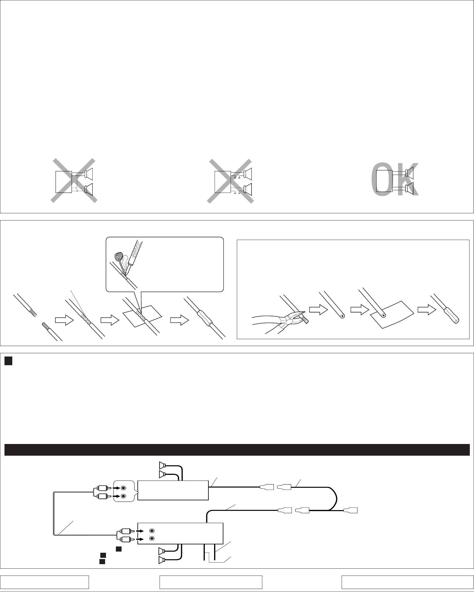
B Connections Adding Other Equipment / / WOU{ô« Èdšô« …eNłô« qOuðWOU{ô« Èdšô« …eNłô« qOuð
WOU{ô« Èdšô« …eNłô« qOuðWOU{ô« Èdšô« …eNłô« qOuð
WOU{ô« Èdšô« …eNłô« qOuð
You can connect an amplifier and other equipment to upgrade
your car stereo system.
•Connect the remote lead (blue with white stripe) to the remote
lead of the other equipment so that it can be controlled through
this unit.
•For amplifier only:
–Connect this unit’s line-out terminals to the amplifier’s line-in
terminals.
–Disconnect the speakers from this unit, connect them to
the amplifier. Leave the speaker leads of this unit unused.
(Cover the terminals of the these unused leads with
insulating tape, as illustrated above.)
u¹dO²Ý “UNł ¡«œ« 5ײ dš« “UNłË u rC qOuð pMJ1
Æ…—UO«
¿p?K?Ý l? ©i?O?ÐôU?Ð j?D?<« ‚—“ô«® b?F?Ð s?Ž r?J?×?²?« pKÝ qË«
‰öš s “UN'UÐ rJײ« r²¹ YO×Ð dšô« “UN−K bFÐ sŽ rJײ«
Æ“UN'« «c¼ ¿∫uB« rC* jI
‡‡j)« ‡ qšœ ·«dÞ« l “UN'« «cN j)« ‡ Ãdš ·«dÞ« qË«
ÆuB« rC* ‡‡Æu?B« rC l rNKË« ¨“UN'« «c¼ s UŽUL« qB«
wDž® ƉULF²Ý« ÊËbÐ “UN'« «c¼ UŽULÝ „öÝ« „dð«
`{u u¼ UL ¨‰“UŽ j¹dAÐ WKLF²*« dOž „öÝô« Ác¼ ·«dÞ«
©ÆvKŽô« w
Amplifier / / uB« rC
INPUT
R
L
R
L
LINE OUT
REAR
L
R
L
R
KS-F150
Rear speakers
WOHK)« UŽUL«
Blue with white stripe
iOÐôUÐ jD ‚—“« pKÝ
(see diagram A ) Front speakers
wDOD²« rÝd« dE½«® A WOUô« UŽUL« ©
Remote lead
bFÐ sŽ rJײ« pKÝ
Y-connector (not supplied with this unit)
‡ quY©“UN'« «c¼ l od dOž®
To automatic antenna if any
błË Ê« wJOðUuðËô« wz«uN« v«
JVC amplifier
lM u rCJVC
!"#$%&'()*
• !"#$%&'&()*+,-./0123456
• !"#$%&"' ! !"#$ !"
! 12V !"#$ !"#$%&'()
• !"#$%&%' !"()*+,-./01 !"
– !"#$%&'()*12 !"#$%&'
!"#$%&'()*+,-./#0-123
!"# 3 !"#$%&'()*+
– !"#$%&'()*3 !"#$%&'()
!"#$%
– !"#$ %&'()*+,-./ 0%&123
• !"#$%&'()*+,%-./012
!"#
!"#$%&'(
!"#$%&'()
!"
!"#$%&'(
!"#$%&'()* +,-./0123456
• ! !"# !"#$%&'()*+,-.
!"#$%&'(
• !"#$%
– !"#$%&'()"*$%+,-./
– !"#$%&'()*+,!-#$. !)/
!" !"#$%&'()*+,-.)%/0
!"
!"#$
!"
Y !" !"#$%
!"#$%
!"
JVC
! !"#$%
!
• !"#
* !"#$%&'!"#$%()*$+?
• !"#$
* !"#$%&'$?
• !"#$
* !"#$%&'()*+?
• !"
* !"#$%&'()?
* !"#$LR !"– !"?
• !"
* !"#$%&'()?
* !"#$LR !"– !"?
!"
! / !
! / !
q³ `O× qJAÐ „öÝô« ÂdЫ
ÆqOu²«
A
CAUTION / / tO³MðtO³Mð
tO³MðtO³Mð
tO³Mð
•To prevent short-circuit, cover the terminals of the UNUSED leads with insulating
tape.
•
·«dÞ« vKŽ oôË ‰“UŽ j¹dý l{ ¨WOzUÐdNJ« ‡‡ dz«Ëb« w dOBI²« lM qł« s·«dÞ« vKŽ oôË ‰“UŽ j¹dý l{ ¨WOzUÐdNJ« ‡‡ dz«Ëb« w dOBI²« lM qł« s
·«dÞ« vKŽ oôË ‰“UŽ j¹dý l{ ¨WOzUÐdNJ« ‡‡ dz«Ëb« w dOBI²« lM qł« s·«dÞ« vKŽ oôË ‰“UŽ j¹dý l{ ¨WOzUÐdNJ« ‡‡ dz«Ëb« w dOBI²« lM qł« s
·«dÞ« vKŽ oôË ‰“UŽ j¹dý l{ ¨WOzUÐdNJ« ‡‡ dz«Ëb« w dOBI²« lM qł« s
WKLF²*« dOž „öÝô«WKLF²*« dOž „öÝô«
WKLF²*« dOž „öÝô«WKLF²*« dOž „öÝô«
WKLF²*« dOž „öÝô«Æ
Signal cord (not supplied with this unit
©“UN'« «c¼ l od dOž® …—Uýô« pKÝ
Green with black stripe / Green (Not used)
©qLF² dOž® dCšô«ØœuÝôUÐ jD dCš« pKÝ
Purple with black stripe / Purple (Not used)
©qLF² dOž® w½«uł—ô«ØœuÝôUÐ jD w½«uł—« pKÝ
•
•
•
•
•
•
Install.KS-F150[U]/1 02/15/2000, 1:04 PM4
