JVC KW AVX900A AVX900[A] Installation User Manual LVT1670 005A
KW-AVX900A KW-AVX900A INSTALLATION MANUAL (Australia) LVT1670-005A
User Manual: JVC KW-AVX900A KW-AVX900A English, INSTALLATION MANUAL
Open the PDF directly: View PDF ![]() .
.
Page Count: 4
When installing the unit in a Nissan car
Plate for use with a Nissan car
KW-AVX900
Installation/Connection Manual
0307MNMMDWJEIN
EN
©2007 Victor Company of Japan, Limited
LVT1670-005A
[A]
This unit is designed to operate on 12 V DC, NEGATIVE ground electrical systems. If your vehicle
does not have this system, a voltage inverter is required, which can be purchased at JVC car audio dealers.
WARNINGS
• DO NOT install any unit and wire any cable in locations where;
– it may obstruct the steering wheel and gearshift lever operations, as this may result in a traffic
accident.
– it may obstruct the operation of safety devices such as air bags, as this may result in a fatal accident.
– it may obstruct visibility.
• DO NOT operate any unit while manipulating the steering wheel, as this may result in a traffic accident.
• The driver must not watch the monitor while driving. If the driver watches the monitor while driving, it
may lead to carelessness and cause an accident.
• The driver must not put on the headphones while driving. It is dangerous to shut off the outside sounds
while driving.
• If you need to operate the unit while driving, be sure to look around carefully or you may be involved in
a traffic accident.
• If the parking brake is not engaged, “Parking Brake” flashes on the monitor, and no playback picture
will be shown.
– This warning appears only when the parking brake wire is connected to the parking brake system
built in the car.
Notes on electrical connections:
• Replace the fuse with one of the specified rating. If the fuse blows
frequently, consult your JVC car audio dealer.
• It is recommended to connect to the speakers with maximum
power of more than 50 W (both at the rear and at the front,
with an impedance of 4 Ω to 8 Ω).
If the maximum power is less than 50 W, change “Amplifier
Gain” setting to prevent the speakers from being damaged (see page 60 of the INSTRUCTIONS).
• To prevent short-circuit, cover the terminals of the UNUSED leads with insulating tape.
• The heat sink becomes very hot after use. Be careful not to touch it when removing this unit.
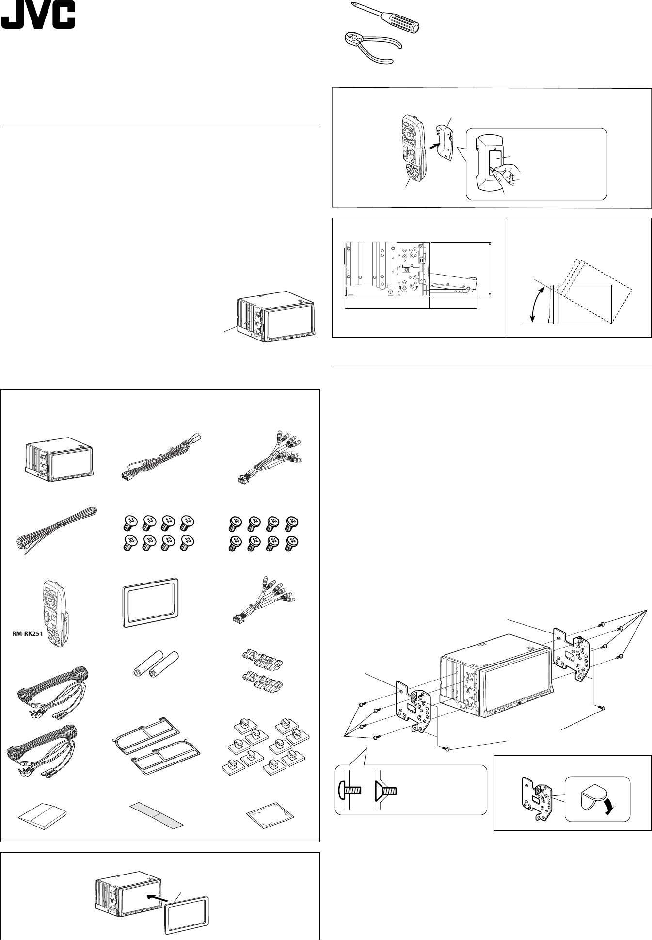
Heat sink
Installing the remote controller
Install the unit at an angle of less than 30˚,
taking it into account that the monitor
would eject when in use.
30˚
160 90.4
100
Required space for the monitor ejection
Unit: mm
Holder
Double-sided adhesive tape
Remote controller
Parts list for installation and connection
The following parts are provided for this unit.
If anything is missing, contact your dealer immediately.
Main unit Power cord AV I/O cord
Round head screws
(M5 x 8 mm)
Flat head screws
(M5 x 8 mm)
Reverse gear signal extension cord
Remote controller / Holder
Batteries
5.1CH (LINE OUT) cord
Crimp connectors
Plate for use with a Nissan car
1
TV aerials
Rubber spatula Cleaner
Clamps
Earth tape
Aerial cords
Note : When installing the unit on the mounting bracket, make sure to use the supplied screws
(M5 x 8 mm). If longer screws are used, they could damage the unit.
INSTALLATION (IN-DASH MOUNTING)
The following illustration shows a typical installation. However, you should make adjustments
corresponding to your specific car. If you have any questions or require information regarding
installation kits, consult your JVC car audio dealer or a company supplying kits.
• If you are not sure how to install this unit correctly, have it installed by a qualified technician.
Before installing the unit
• When mounting the unit, be sure to use the screws provided, as instructed. If other screws are used,
parts could become loose or damaged.
• When tightening screws or bolts, be careful not to pinch any connection cord.
• Make sure not to block the fan on the rear panel to maintain proper ventilation when installed.
1 Remove the audio system originally installed in the car, together with its mounting brackets.
Note: Be sure to keep all the screws and parts removed from your car for future use.
2 Attach the mounting brackets (removed from the car), to this unit (see below).
3 Connect the supplied cords.
• See page 2 for connecting the power cord.
• See page 3 for connecting the TV aerials, AV I/O cord and reverse gear signal extension cord.
• See page 4 for connecting the 5.1CH (LINE OUT) cord.
4 Install this unit using the screws removed in step 1.
The following example is for installation in a Toyota car. For more details, consult your JVC car audio
dealer.
Screws removed from the car in step 1
Supplied screws
Mounting bracket removed
from the car
Mounting bracket removed from the car
Supplied
screws
Select the appropriate
type fitting to your
audio system space.
If necessary, restore the protruding tabs.
Instal_KW-AVX900[A]_1.indd 1Instal_KW-AVX900[A]_1.indd 1 2007.3.20 1:12:26 PM2007.3.20 1:12:26 PM
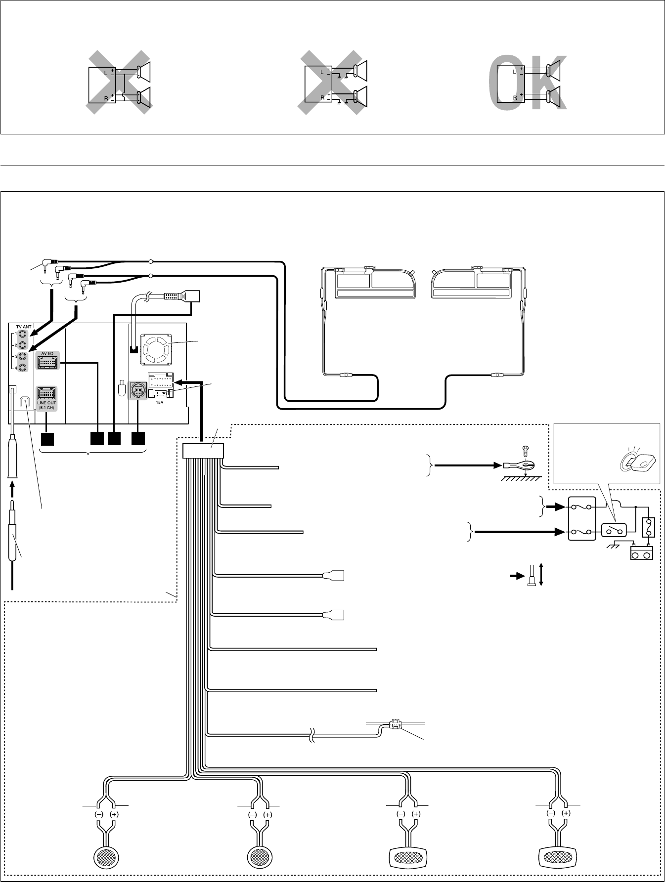
PRECAUTIONS on power supply and speaker connections:
• DO NOT connect the speaker leads of the power cord to the car battery; otherwise, the unit will be seriously damaged.
• BEFORE connecting the speaker leads of the power cord to the speakers, check the speaker wiring in your car.
2
ELECTRICAL CONNECTIONS
To prevent short circuits, we recommend that you disconnect the battery’s negative terminal and make all electrical connections before installing the unit.
• Be sure to ground this unit to the car’s chassis again after installation.
Before connecting: Check the wiring in the vehicle carefully. Incorrect connection may cause serious damage to this unit.
The leads of the power cord and those of the connector from the car body may be different in color.
1 Connect the colored leads of the power cord in the order specified in the illustration below.
2 Connect the aerial cord and TV aerials. (For installing and attaching the TV aerials, see diagram Å on page 3.)
3 Finally connect the wiring harness to the unit.
1
2
3
4
6
9
7
1
(ILLUMINATION)
(TEL MUTING)
(PARKING BRAKE)
3
C
BA
8
2
2
C
(POWER ANTENNA)
5
(REMOTE OUT)
15 A fuse
Rear ground terminal
*1 Not included for this unit Ignition switch
White with black stripe White Gray with black stripe Gray Green with black stripe Green Purple with black stripe Purple
Right speaker (front) Left speaker (rear) Right speaker (rear)
To metallic body or chassis of the car
To a live terminal in the fuse block connecting to the car battery (bypassing
the ignition switch)
To an accessory terminal in the fuse block
To car light control switch
To cellular phone system
Black
Yellow *2
Red
Blue with white stripe
Orange with white stripe
Brown
Light green
To the remote lead of other equipment (200 mA max.)
*1
*1
Left speaker (front)
*2
Before checking the operation of this unit prior to
installation, this lead must be connected, otherwise
power cannot be turned on.
Crimp connector
To parking brake of the car (see diagram ı on page 3.)
Fuse block
See pages 3 and 4.
Fan
TV aerial (Left) TV aerial (Right)
To automatic antenna if any (250 mA max.)
Blue
Instal_KW-AVX900[A]_1.indd 2Instal_KW-AVX900[A]_1.indd 2 2007.3.14 5:12:50 PM2007.3.14 5:12:50 PM
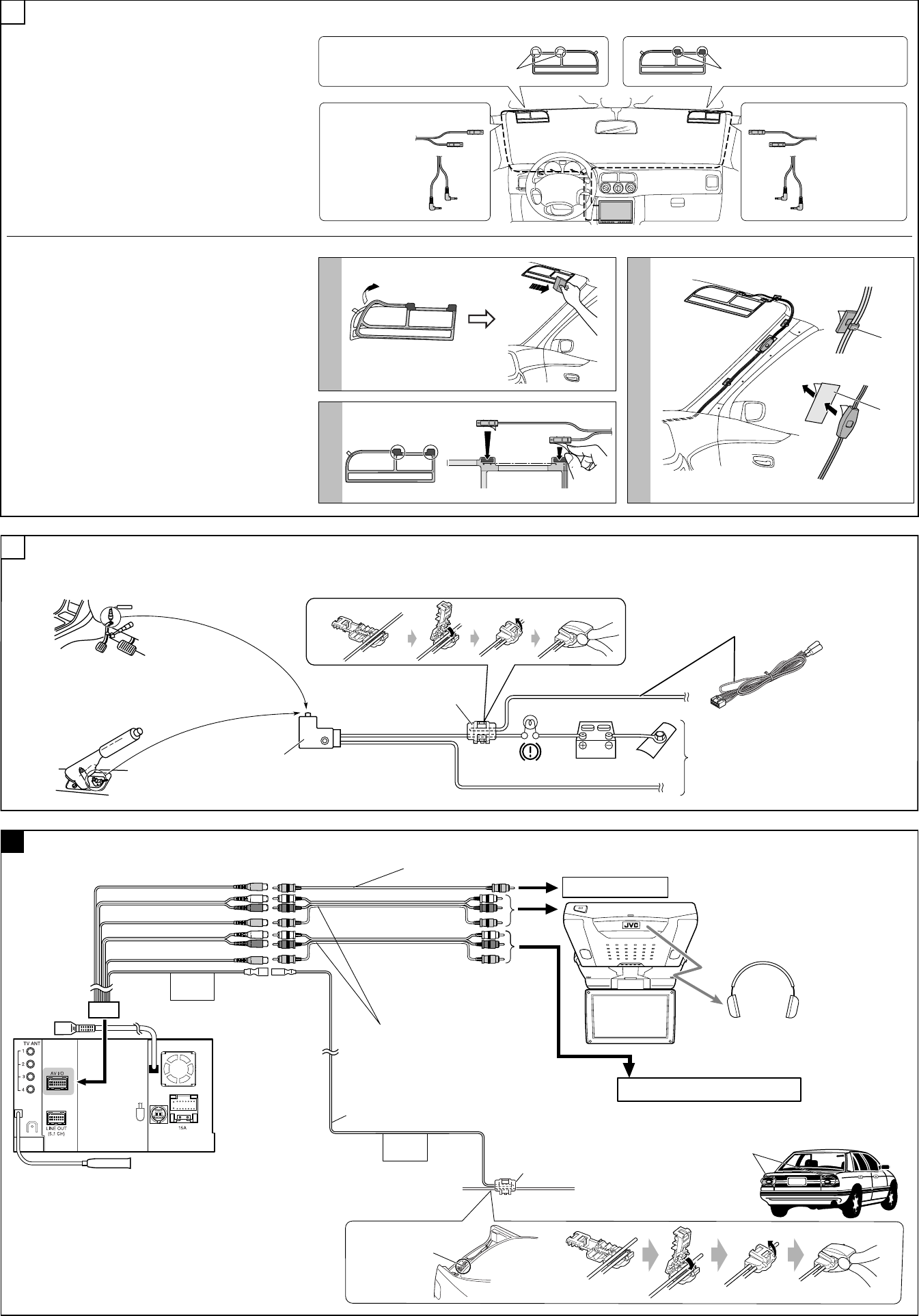
3
CAMERA IN
VIDEO OUT
LINE IN
VIDEO IN
REVERSE
GEAR
SIGNAL
2nd AUDIO OUT
REVERSE
GEAR
SIGNAL
L
R
L
R
L
R
L
R
*3 Required only when connecting a rear view camera to CAMERA IN plug.
2nd monitor (KV-MR9010, etc.)
Reverse lamp lead
To car battery
Cordless headphones (KS-HP2)
Reverse lamp
To reverse lamp
Reverse gear signal extension cord *3
Crimp connector
Connecting the AV I/O cord
Audio/video cords (not supplied)
Video cord (not supplied)
Navigation System or playback source
To rear view camera
A
Connecting the parking brake lead
Connect the parking brake lead to the parking brake system built in the car.
To metallic body or chassis of the car
Parking brake switch (inside the car)
Parking brake
B
Parking brake lead (light green)
Crimp connector
Installing the TV aerials
Before installing:
• Attach the aerials only to the inside of the front window glass
(so as not to obstruct your visibility through the window).
• Do not rub the aerials or the aerials’ cords with alcohol,
benzine, thinner, gasoline or other volatile substances.
• Be sure to wipe the window surface where the aerials will be
attached with the cleaner (supplied) to remove moisture, dirt,
dust, wax, oil or other substances.
• The windows with windshield heating, wave insulated, or
thermally insulated screen will interfere with signal reception.
Consult your JVC car audio dealer.
• For connecting the TV aerials to the unit, see page 2.
TV aerial (Left)
Aerial cords Aerial cords
TV aerial (Right)
White Red
• Aerial cords are
identical both for
the left and right TV
aerials.
Attaching the TV aerials
Before attaching:
• Identify the exact attachment location and confirm that the
aerials will not interfere with other aerial receptions (at least
10 cm away from the other aerials). Once you attach the aerials,
you can hardly remove them.
1 Attach the aerials on the front windshield.
• Rub on the aerials with the rubber spatula (supplied) to firmly
fix them on the glass.
2 Attach the aerial cords to the electrodes of the aerials.
3 Wire the cords along the pillars, and secure them using the cord
clamps.
• Remove the pillar covers, and wire the cords so that the earth
section of the cord can touch the metallic part of the car.
4 After wiring is done, attach the pillar covers.
1
2
3
Clamps
Earth tape
A
Instal_KW-AVX900[A]_1.indd 3Instal_KW-AVX900[A]_1.indd 3 2007.3.14 5:12:51 PM2007.3.14 5:12:51 PM

4
KS-U57
KS-U58
KS-PD500
KS-PD100
To disconnect the connector
Hold the connector top tightly (1), then pull it out (2).
C
JVC CD changer
External component with RCA pin jacks
External component with stereo-mini jack
or
or
or
JVC Bluetooth adapter
*5
You can connect external components in series as shown in the diagram below.
• All the components, adapters or signal cords need to be purchased separately.
CAUTION:
Before connecting the external components, make sure that the unit is turned off.
• To use JVC CD changer, Apple iPod or JVC D. player, set “External Input” to “Changer/iPod/D. Player” (see page 59 of the INSTRUCTIONS).
• To use other external components via KS-U57 or KS-U58, set “External Input” to “External” (see page 59 of the INSTRUCTIONS).
• iPod is a trademark of Apple Inc., registered in the U.S. and other countries.
USB cable (approx. 1.2 m)
USB device
• You cannot connect a computer to the USB ( )
terminal of the unit.
CD changer jack
USB devices
Connecting external components
iPod
JVC D. Player XA-HD500
*5 Audio cord (not supplied) is required.
or
LRL
L
INPUT
INPUT
INPUT
R
L
INPUT
R
L
R
L
R
R
*
4
*
4
*
4
*
4
LINE OUT (FRONT)
LINE OUT (REAR)
SUBWOOFER
CENTER OUT
You can connect amplifiers to upgrade surround system in the car compartment.
• Connect the amplifiers to 5.1-ch analog discrete output plugs to enjoy multi-channel source.
• After you have connected the center speaker, make sure to activate the center speaker; otherwise, no sound comes out of the connected center speaker, see page 57 of the INSTRUCTIONS.
• You can supply the power to the amplifiers by connecting the remote leads (blue with white stripe) of this unit and amplifiers. (To connect more than one amplifier using the remote leads, Y-connectors need to
be separately purchased.)
• Disconnect the speakers from the unit, and connect them to the amplifier. Leave the speaker leads of the unit unused.
*4 Firmly attach the ground wire to the metallic body or to the chassis of the car—to the place uncoated with paint (if coated with paint, remove the paint before attaching the wire). Failure to do so may cause
damage to the unit.
Subwoofer
Rear speakers
Center speaker
JVC Amplifier
Front speakers
JVC Amplifier
JVC Amplifier
JVC Amplifier
Connecting the external amplifiers
B
TROUBLESHOOTING
• The fuse blows.
* Are the red and black leads connected correctly?
• Power cannot be turned on.
* Is the yellow lead connected?
• No sound from the speakers.
* Is the speaker output lead short-circuited?
• Sound is distorted.
* Is the speaker output lead grounded?
* Are the “–” terminals of L and R speakers grounded in common?
• Noise interfere with sounds.
* Is the rear ground terminal connected to the car’s chassis using shorter and thicker cords?
• Unit becomes hot.
* Is the speaker output lead grounded?
* Are the “–” terminals of L and R speakers grounded in common?
• This unit does not work at all.
* Have you reset your unit?
Instal_KW-AVX900[A]_1.indd 4Instal_KW-AVX900[A]_1.indd 4 2007.3.14 5:12:53 PM2007.3.14 5:12:53 PM
