JVC KW XG705U/UH Install1_KW XG706_009A_2 User Manual GET0458 006A
KW-XG706U/UH KW-XG706U/UH GET0458-006A English, Thai, INSTALLATION MANUAL
KW-XG705U/UH KW-XG705U/UH INSTALLATION MANUAL GET0458-006A
User Manual: JVC KW-XG705U/UH KW-XG705U/UH English, Thai, INSTALLATION MANUAL
Open the PDF directly: View PDF ![]() .
.
Page Count: 4

1
KW-XG706/KW-XG705
Installation/Connection Manual
°“√μ‘¥μ—Èß/§ŸË¡◊Õ°“√μ‘¥μ—Èß
0407DTSMDTJEIN
EN, TH
Battery
·∫μ‡μÕ√ Remote controller
√’‚¡μ§Õπ‚∑√≈
Binding screws (M5 × 8 mm)
°√Ÿ¬÷¥ (M5 × 8 ¡¡.)
Power cord
“¬‡§‡∫‘≈°”≈—ß
Flat countersunk screws (M5 × 8 mm)
°√ŸÀ—«‡√’¬∫ (M5 × 8 ¡¡.)
© 2007 Victor Company of Japan, Limited
GET0458-006A
[U/UH]
ENGLISH
This unit is designed to operate on 12 V DC, NEGATIVE ground electrical systems. If your vehicle does
not have this system, a voltage inverter is required, which can be purchased at JVC car audio dealers.
WARNINGS
To prevent short circuits, we recommend that you disconnect the battery’s negative terminal and make all
electrical connections before installing the unit.
• Be sure to ground this unit to the car’s chassis again after installation.
Notes:
• Replace the fuse with one of the specified rating. If the fuse blows frequently, consult your JVC car audio
dealer.
• If noise is a problem...
This unit incorporates a noise filter in the power circuit. However, with some vehicles, clicking or other
unwanted noise may occur. If this happens, connect the unit’s rear ground terminal to the car’s chassis
using shorter and thicker cords, such as copper braiding or gauge wire. If noise still persists, consult
your JVC car audio dealer.
• It is recommended to connect to the speakers with maximum power of more than 50 W (both at the rear
and at the front, with an impedance of 4 Ω to 8 Ω). If the maximum power is less than
50 W, change “AMP GAIN” setting to prevent the speakers from being damaged (see page 25 of the
INSTRUCTIONS).
• The heat sink becomes very hot after use. Be careful not to touch it when removing this unit.
‰∑¬
™ÿ¥ª√–°Õ∫π’ȉ¥È√—∫°“√ÕÕ°·∫∫¡“‡æ◊ËÕ„™Èß“π°—∫√–∫∫ °√–·‰øøÈ““¬¥‘π¢—È«≈∫°√–·μ√ß 12 ‚«≈∑Ï À“°√∂¬πμÏ¢Õߧÿ≥‰¡Ë‰
¥È„™È√–∫∫π’È μÈÕß„™È‡§√◊ËÕß·ª≈ß°√–·‰ø™Ë«¬ ´÷Ëß“¡“√∂À“´◊ÈÕ‰¥È®“°√È“π¢“¬‡§√◊ËÕ߇’¬ß√∂¬πμÏ JVC
§”‡μ◊Õπ
æ◊ËÕªÈÕß°—π°“√‡°‘¥‰øøÈ“≈—¥«ß®√ ¢Õ·π–π”„ÀȪ≈¥¢—È«·∫μ‡μÕ√’Ë≈∫ÕÕ° ·≈È«®÷ßμËÕ“¬‰ø°ËÕπμ‘¥μ—È߇§√◊ËÕß
• μ√«®Õ∫„ÀÈ·πË„®«Ë“‰¥È‡¥‘𓬥‘πμËÕ√–À«Ë“߇§√◊ËÕß°—∫μ—«∂—ß √∂¬πμÏ„À¡Ë·≈È«À≈—ß®“°μ‘¥μ—Èß
À¡“¬‡Àμÿ:
• „™Èæ‘°—¥®”‡æ“–·∑πø‘« À“°ø‘«Ï¢“¥∫ËÕ¬ „ÀȪ√÷°…“√È“ π¢“¬‡§√◊ËÕ߇’¬ß√∂¬πμÏ JVC
• À“°¡’‡’¬ß√∫°«π...
‡§√◊ËÕß√—∫—≠≠“≥√ÿËππ’ȉ¥Èª√–°Õ∫Õÿª°√≥Ï°”®—¥‡’¬ß√∫°«π‰«È∑’Ë·ºß«ß®√ լ˓߉√°Áμ“¡ „π√∂¬πμÏ∫“ß√ÿËπÕ“®¡’‡’¬ß
√∫°«π‡°‘¥¢÷Èπ À“°‡°‘¥‡’¬ß¥—ß°≈Ë“«¢÷Èπ „ÀÈμËÕ¢—È«μËÕ“¬¥‘π¥È“πÀ≈—ߢÕßμ—«‡§√◊ËÕß ‰ª∑’Ë·™´’¢Õß
√∂‚¥¬„™È“¬‰ø∑’ËÀπ“¡“°¢÷Èπ·≈–—Èπ≈߇™Ë𠓬‡°®À√◊Õ≈«¥∂∂—°™ÿ∫∑Õß·¥ß À“°¬—ß¡’‡’¬∫√∫°«π¥—ß°≈Ë“«‡°‘¥¢÷È𠂪√¥μ‘¥μËÕμ—
«·∑π®”ÀπË“¬‡§√◊ËÕ߇’¬ß√∂¬πμÏ JVC
• ¢Õ·π–π”„ÀÈμËÕ≈”‚æß ∑’Ë¡’°”≈—ߢ—∫ßÿ¥‡°‘π°«Ë“ 50 W (∑—ÈߥȓπÀπÈ“·≈–¥È“πÀ≈—ß ¡’§Ë“§«“¡μÈ“π∑“π 4 ∂÷ß 8 )
∂È“°”≈—ߢ—∫μË”°«Ë“ 50 W „Àȇª≈’ˬπ§Ë“ “AMP GAIN” ‡æ◊ËÕªÈÕß°—π‰¡Ë„ÀÈ≈”‚æß™”√ÿ¥ (¥ŸÀπÈ“ 25 §”·π–π”)
• ·ºËπ√–∫“¬§«“¡√ÈÕπ®–√ÈÕπ¡“°À≈—ß®“°„™È √–¡—¥√–«—ßլ˓‰ª —¡º—‡¡◊ËÕ∂Õ¥™ÿ¥ª√–°Õ∫π’È
Parts list for installation and connection
The following parts are provided for this unit. If any item is missing, consult your JVC car audio dealer
immediately.
√“¬°“√Ë«πª√–°Õ∫”À√—∫μ‘¥μ—Èß·≈–‡™◊ËÕ¡μËÕ°—π
Ë«πª√–°Õ∫μËÕ‰ªπ’È„ÀÈ¡“°—∫™ÿ¥ª√–°Õ∫π’È À“°¡’‘Ëß„¥‰¡Ë§√∫ °√ÿ≥“ª√÷°…“μ—«·∑π®”ÀπË“¬‡§√◊ËÕ߇’¬ßμ‘¥√∂¬πμÏ JVC ‚¥¬∑—π∑’
Plate for use with a Nissan car
·ºËπÌ“À√—∫„™Ñ°—∫√∂π‘—π
When installating the unit in a Nissan car
‡¡óòÕ∑Ì“°“√μî¥μíôß„π√∂π‘—π
Fix the supplied plate as illustrated.
¬÷¥·ºàπ∑’Ë¡’¡“„ÀÑ ¥íß∑’Ë·¥ß„π¿“æ
Plate for use with a Nissan car
·ºËπÌ“À√—∫„™Ñ°—∫√∂π‘—π
TROUBLESHOOTING
• The fuse blows.
* Are the red and black leads connected correctly?
• Power cannot be turned on.
* Is the yellow lead connected?
• No sound from the speakers.
* Is the speaker output lead short-circuited?
• Sound is distorted.
* Is the speaker output lead grounded?
* Are the “–” terminals of L and R speakers grounded in common?
• Noise interfere with sounds.
* Is the rear ground terminal connected to the car’s chassis using shorter and thicker cords?
• This unit becomes hot.
* Is the speaker output lead grounded?
* Are the “–” terminals of L and R speakers grounded in common?
• This unit does not work at all.
* Have you reset your unit?
°“√μ√«®Õ∫ªí≠À“¢—¥¢ÈÕß
• øî«Ï¢“¥
* ¡’°“√‡™◊ËÕ¡ “¬μ–°—Ë«’¥”·≈–’·¥ßլ˓ß∂Ÿ°μÈÕßÀ√◊Õ‰¡Ë
• ‰¡Ë“¡“√∂‡ªî¥‡§√◊ËÕ߉¥È
* ¡’°“√‡™◊ËÕ¡“¬μ–°—Ë«’‡À≈◊ÕßÀ√◊Õ‰¡Ë
• ‰¡Ë¡’‡’¬ßÕÕ°®“°≈”‚æß
* “¬μ–°—Ë«Ë«π∑’ËÕÕ°∑“ß≈”‚æ߇°‘¥‰øøÈ“≈—¥«ß®√À√◊Õ‰¡Ë
• ‡’¬ß‡æ’Ȭπ
* “¬μ–°—Ë«Ë«π∑’ËÕÕ°∑“ß≈”‚æßμËÕ≈ߥ‘πÀ√◊Õ‰¡Ë
* “¬¢—È«≈∫ “–” ¢Õß≈”‚æߥȓπ´È“¬·≈–¢«“μËÕ≈ߥ‘πμ“¡ª°μ‘À√◊Õ‰¡Ë
• ‡’¬ß√∫°«π
* ¡’°“√„™È“¬—ÈπÊ À√◊ÕÀπ“Ê μËÕ®“°‡§√◊ËÕß«π∑’Ëμ‘¥μ—Èß ‰«È∫πæ◊Èπ¥È“πÀ≈—ß°—∫μ—«∂—ß√∂¬πμÏÀ√◊Õ‰¡Ë
• ™ÿ¥ª√–°Õ∫√ÈÕπ¢÷Èπ
* “¬μ–°—Ë«Ë«π∑’ËÕÕ°∑“ß≈”‚æßμËÕ≈ߥ‘πÀ√◊Õ‰¡Ë
* “¬¢—È«≈∫ “–” ¢Õß≈”‚æߥȓπ´È“¬·≈–¢«“μËÕ≈ߥ‘πμ“¡ª°μ‘À√◊Õ‰¡Ë
• ‡§√◊ËÕß√—∫π’È∑”ß“π‰¡
* ∑Ë“π‰¥Èμ—È߇§√◊ËÕß„À¡Ë·≈È«À√◊Õ¬—ß
Heat sink
·ºËπ√–∫“¬§«“¡√ÈÕπ
Rear view
¡ÿ¡¡ÕߥȓπÀ≈—ß
Install1_KW-XG706_009A_2.indd 1Install1_KW-XG706_009A_2.indd 1 4/13/07 2:48:02 PM4/13/07 2:48:02 PM

2
°“√μ‘¥μ—Èß (°“√ª√–°Õ∫·ºßÀπÈ“ªí∑¡Ï‡¢È“)
¿“æμ—«Õ¬Ë“ßμËÕ‰ªπ’È·¥ß°“√μ‘¥μ—Èß·∫∫∑—Ë«‰ª լ˓߉√°Áμ“¡§ÿ≥“¡“√∂∑”°“√ª√—∫‰¥Èμ“¡≈—°…≥–¢Õß√∂§ÿ≥ „π°√≥’¥—ß°≈Ë“«
‚ª√¥μ‘¥μËÕ¢Õ§”·π–π”®“°μ—«·∑π®”ÀπË“¬‡§√◊ËÕ߇’¬ß JVC À√◊Õ∫√‘…—∑∑’Ë®—¥®”ÀπË“¬™ÿ¥ª√–°Õ∫
„π∫“ß°√≥’ ¢÷ÈπÕ¬ŸË°—∫™π‘¥·≈–√ÿËπ¢Õß√∂¬πμÏ ‡æ√“–Õ“®μ‘¥μ—È߇§√◊ËÕ߉«È∑’Ëμ”·ÀπËߧÕπ‚´≈°≈“߉¡Ë‰¥È
À“°§ÿ≥¡’¢ÈÕß—¬À√◊ÕμÈÕß°“√¢ÈÕ¡Ÿ≈‡æ‘Ë¡‡μ‘¡‡°’ˬ«°—∫™ÿ¥ª√–°Õ∫ ‚ª√¥μ‘¥μËÕμ—«·∑π®”ÀπË“¬‡§√◊ËÕ߇’¬ß√∂¬πμÏ JVC
À√◊Õ∫√‘…—∑∑’Ë®—¥®”ÀπË“¬™ÿ¥ª√–°Õ∫
• ™ÿ¥ª√–°Õ∫ ∂È“§ÿ≥‰¡Ë·πË„®«Ë“μ‘¥μ—Èß™ÿ¥ª√–°Õ∫π’È∂Ÿ°μÈÕßÀ√◊Õ‰¡Ë „ÀÈÀ“™Ë“ߺŸÈ‡™’ˬ«™“≠‡ªÁπºŸÈμ‘¥μ—Èß
°ËÕπ°“√μ‘¥μ—Èßμ—«‡§√◊ËÕß
• ‡¡◊ËÕ®–∑”°“√μ‘¥μ—Èßμ—«‡§√◊ËÕß ‚ª√¥„™È°√Ÿ∑’Ë·π∫¡“μ“¡∑’Ë·π–π” À“°§ÿ≥¬÷¥‡§√◊ËÕߥȫ¬°√Ÿ·∫∫Õ◊Ëπ Õ“®∑”„ÀÈ™‘ÈπË«πÀ≈«¡À√◊Õ
‡°‘¥§«“¡‡’¬À“¬‰¥È
• ‡¡◊ËÕ®–¢—π·πËπ°√ŸÀ√◊Õ≈—°‡°≈’¬« μÈÕß√–«—߉¡Ë„ÀÈÀπ’∫“¬‡™◊ËÕ¡μËÕ
INSTALLATION (IN-DASH MOUNTING)
The following illustration shows a typical installation. However, you should make adjustments
corresponding to your specific car. In this case consult the manual included with the installation kit.
In some case, depending on the type and the model of your car, it is not possible to install the unit into the
center console. If you have any questions or require information regarding installation kits, consult your
JVC car audio dealers or a company supplying kits.
• If you are not sure how to install this unit correctly, have it installed by a qualified technician.
Before installing the unit
• When mounting the unit, be sure to use the screws provided, as instructed. If other screws are used,
there is a possibility that parts could become loose or damaged.
• When tightening screws or bolts be careful not to pinch any connection cord.
1 Remove the audio system originally installed together with the mounting brackets.
Note: Be sure to keep all the screws and parts removed from your car for future use.
2 Attach the mounting brackets (removed from the car), to this unit (see below).
3 Connect the wires (see diagram ).
4 Fix this unit to the car using the screws removed in step 1.
• See “Caution” below.
The following example shown is for installation in a Toyota. For more details, consult your JVC
car audio dealer.
1 ∂Õ¥≈”‚æß∑’˪√–°Õ∫‡¢È“‰ª°—∫·∑Ëπ√Õß√—∫
À¡“¬‡Àμÿ: ‚ª√¥‡°Á∫°√Ÿ·≈–™‘ÈπË«π∑—ÈßÀ¡¥∑’Ë∂Õ¥ÕÕ°‰«È„™Èß“π„π§√“«μËÕ‰ª
2 ª√–°Õ∫·∑Ëπ√Õß√—∫ (∑’Ë∂Õ¥ÕÕ°®“°√∂) ‡¢È“°—∫μ—«‡§√◊ËÕß (‚ª√¥¥Ÿ¥È“π≈Ë“ß)
3 μËÕ“¬‰ø (¥Ÿ·ºπ¿Ÿ¡‘ )
4 ¬÷¥μ—«‡§√◊ËÕ߇¢È“°—∫√∂¥È«¬°√Ÿ∑’Ë∂Õ¥ÕÕ°„π¢—ÈπμÕπ∑’Ë 1
• ‚ª√¥ÕË“π “¢ÈÕ§«√√–«—ß” ¥È“π≈Ë“ß
μ—«Õ¬Ë“ßμËÕ‰ªπ’ȇªÁπ°“√μ‘¥μ—È߇§√◊ËÕß√—∫—≠≠“≥„π√∂¬πμÏ‚μ‚¬μÈ“ ”À√—∫√“¬≈–‡Õ’¬¥‡æ‘Ë¡‡μ‘¡ ‚ª√¥μ‘¥μËÕ¢Õ§”·π–
π”‰¥È®“°μ—«·∑π®”ÀπË“¬‡§√◊ËÕ߇’¬ß√∂¬πμÏ JVC
Screws supplied for this unit
°√Ÿ∑’Ë„æ’æ√ÑÕ∫°í∫‡§√’ËÕß
Mounting bracket removed from the car
·∑Ëπ√Õß√—∫∑’Ë∂Õ¥ÕÕ°®“°√∂
Screws supplied for this unit
°√Ÿ∑’Ë„æ’æ√ÑÕ∫°í∫‡§√’ËÕß
Screw removed from the car in step 1
°√Ÿ∑’Ë∂Õ¥ÕÕ°®“°√∂„π¢—ÈπμÕπ∑’Ë 1
Securely connect the ground wire to the metal body of the car using the
screw originally fixed to the metal body of the car.
μËÕ“¬¥‘π‡¢È“°—∫‚§√ß‚≈À–¢Õß√∂„ÀÈ·πËπ¥È«¬°√Ÿ∑’ˬ÷¥‚§√ß‚≈À–¢Õß√∂
Mounting bracket removed from the car
·∑Ëπ√Õß√—∫∑’Ë∂Õ¥ÕÕ°®“°√∂
Screws supplied for this unit:
°√Ÿ∑’Ë„æ’æ√ÑÕ∫°í∫‡§√’ËÕß:
Select the proper screw type, fitting to your car.
‡≈◊Õ°„™Ñ™π‘¥°√Ÿ„ÀчÀ¡“–¡°—∫√∂¢Õߧÿê Binding screws (M5 × 8 mm)
°√Ÿ¬÷¥ (M5 × 8 ¡¡.)
Flat countersunk screws (M5 × 8 mm)
°√ŸÀ—«‡√’¬∫ (M5 × 8 ¡¡.)
Caution:
To install the mounting brackets to the unit, use only the supplied screws (M5 × 8 mm).
If you use any screw longer than 8 mm, the unit can be damaged.
¢ÈÕ§«√√–«—ß:
„π°“√ª√–°Õ∫·∑Ëπ√Õß√—∫°—∫μ—«‡§√◊ËÕß ‚ª√¥„™È°√Ÿ (M5 × 8 ¡¡.) ∑’Ë„ÀÈ¡“‡∑Ë“π—Èπ
À“°§ÿ≥„™È°√Ÿ∑’ˬ“«°«Ë“ 8 ¡¡. Õ“®∑”„ÀÈμ—«‡§√◊ËÕ߉¥È√—∫§«“¡‡’¬À“¬
Install the unit at an angle of less than 30°.
μ‘¥μ—Èß™ÿ¥ª√–°Õ∫∑’Ë¡ÿ¡μË”°«Ë“ 30 Õß»“
If there is an interfering tab on the mounting bracket,
bend it flat.
À“°¡’Ë«π∑’ˬ◊ËπÕÕ°¡“®“°·∑Ëπ√Õß√—∫ „ÀÈ¥—¥Ë«π¥—ß°≈Ë“«„ÀÈ√“∫≈ß
Install1_KW-XG706_009A_2.indd 2Install1_KW-XG706_009A_2.indd 2 4/13/07 2:48:05 PM4/13/07 2:48:05 PM

3
ATypical connections / °“√‡™◊ËÕ¡μËÕ·∫∫ª°μ‘
Before connecting: Check the wiring in the vehicle carefully. Incorrect connection may cause serious
damage to this unit.
The leads of the power cord and those of the connector from the car body may be different in color.
1 Connect the colored leads of the power cord in the order specified in the illustration below.
2 Connect the antenna cord.
3 Finally connect the wiring harness to the unit.
ENGLISH ‰∑¬
°ËÕ•∑”°“•‡™•ËÕ¡μËÕ: μ•«®†Õ•°“•‡¥‘•†“¬‰ø„•••¬•μÏլ˓ߕ–¡—¥•–«—լ˓„ÀȺ‘¥æ•“¥„•°“•‡™•ËÕ¡μËÕ™ÿ¥ª•–°Õ•™ÿ¥•’
°“•‡™•ËÕ¡μËÕº‘¥æ•“¥Õ“®∑”„Àȇ°‘¥§«“¡‡’¬À“¬•È“¬·•ß°—•™ÿ¥ª•–
°Õ••’ȉ¥È“•μ–°—Ë«¢Õ߆“¬‰ø ·•–¢ÕßÕÿª°••ÏμËÕ‡™•ËÕ¡®“°μ—«• ß••Õ“®¡’’ ∑’ˉ¡Ë‡À¡•Õ•°—
1 μËÕ“¬‰ø’μ“¡≈”¥—∫∑’Ë√–∫ÿ„π√Ÿª¥È“π≈Ë“ß
2 ‡™◊ËÕ¡μËÕ°—∫“¬Õ“°“»
3 ÿ¥∑È“¬ μËÕË«π§«∫§ÿ¡°“√‡¥‘𓬉ø‡¢È“°—∫™ÿ¥ª√–°Õ∫™ÿ¥π’È
*1 Not supplied for this unit.
*2 Before checking the operation of this unit prior to installation, this lead must be connected, otherwise power
cannot be turned on.
*1 ‰¡Ë‰¥È„ÀÈ¡“°—∫™ÿ¥ª√–°Õ∫π’È
*2 °ËÕπ°“√μ√«®Õ∫°“√∑”ß“π¢Õß™ÿ¥ª√–°Õ∫π’È°ËÕπ∑’Ë®–μ‘¥μ—Èß μÈÕßμËÕ“¬μ–°—Ë«π’È°ËÕπ¡‘©–π—Èπ®–‰¡“¡“√∂‡ª‘¥‡§√◊ËÕ߉¥
Line out (see diagram )
“¬ÕÕ° (¥Ÿ·ºπ¿Ÿ¡‘ )
15 A fuse
ø‘«Ï¢π“¥ 15 A
Black
’¥”
Blue with white stripe
’πÈ”‡ß‘π≈“¬¢“«
Red
’·¥ß
Yellow *2
’‡À≈◊Õß *2
Brown
’πÈ”μ“≈
To metallic body or chassis of the car
μËÕ°—∫‚§√ß‚≈À–À√◊Õ‡™´‘¢Õß√∂¬πμá
Ignition switch
«‘∑™Ï®ÿ¥√–‡∫‘¥
Fuse block
·ºßø‘«
To an accessory terminal in the fuse block
μËÕ°—∫¢—È«Ë«πª√–°Õ∫„π·ºßø‘«
To the remote lead of other equipment (200 mA max.)
μËÕ‡¢È“°—∫Õª°√≥ÏÕË◊π (¢π“¥Ÿß¸¥ 200 mA)
To cellular phone system
μËÕ°—∫‚∑√»—æ∑χ§≈◊ËÕπ∑’Ë
White with black stripe
’¢“«·∂∫¥”
To a live terminal in the fuse block connecting to the car battery (bypassing
the ignition switch) (constant 12 V)
μËÕ°—∫¢—È«∑’Ë¡’°√–·‰øøÈ“„π·ºßø‘«Ï ´÷ËßμËÕ°—∫·∫μ‡μÕ√’Ë√∂¬πμ
(‚¥¬‰¡ËμÈÕß„™È«‘∑™Ï®ÿ¥√–‡∫‘¥) (12 ‚«≈∑ϧß∑’Ë)
To external components (see diagram )
™ËÕ߇’¬∫μËÕ¢ÕßÕÿª°√≥Ï¿“¬πÕ° (¥Ÿ·ºπ¿Ÿ¡‘ )
To car light control switch
«‘μ´Ï§«∫§ÿ¡‰ø¢Õß√∂¬πμ√Ï
Orange with white stripe
’È¡·∂∫¢“«
To subwoofer (see diagram )
‰ª´—ø«Ÿø‡«Õ√Ï (¥Ÿ·ºπ¿Ÿ¡‘ )
Antenna terminal
¢—È«“¬Õ“°“»
Purple
’¡Ë«ß
Purple with black stripe
’¡Ë«ß·∂∫¥”
Green
’‡¢’¬«
Green with black stripe
’‡¢’¬«·∂∫¥”
Gray
’‡∑“
Gray with black stripe
’‡∑“·∂∫¥”
White
’¢“«
Right speaker (rear)
≈”‚æߢ«“ (À≈—ß)
Left speaker (rear)
≈”‚æß´È“¬ (À≈—ß)
Right speaker (front)
≈”‚æߢ«“ (ÀπÈ“)
Left speaker (front)
≈”‚æß´È“¬ (ÀπÈ“)
To the automatic antenna if any (250 mA max.)
‡“Õ“°“»‰øøÈ“Õ—μ‚π¡—μ‘ À“°¡’ (¢π“¥Ÿß¸¥ 250 mA)
Blue
»’øÈ“
PRECAUTIONS on power supply and speaker connections:
• DO NOT connect the speaker leads of the power cord to the car battery; otherwise, the unit
will be seriously damaged.
• BEFORE connecting the speaker leads of the power cord to the speakers, check the speaker wiring in
your car.
¢ÈÕ§«√√–«—ß”À√—∫°“√μËÕ·À≈Ë߮˓¬°”≈—ß·≈–≈”‚æß:
• լ˓μËÕ“¬μ–°—Ë«‡§‡∫‘≈°”≈—ߢÕß≈”‚æ߇¢È“°—∫·∫μ‡μÕ√’Ë√∂¬πμÏ ¡‘©–π—Èπ ™ÿ¥ª√–°Õ∫®–‰¥È√—∫§«“¡‡’¬À“¬¡“°
• °ËÕπ∑’Ë®–μËÕ“¬μ–°—Ë«‡§‡∫‘≈°”≈—ߢÕß≈”‚æ߇¢È“°—∫≈”‚æß „ÀÈμ√«®Õ∫°“√‡¥‘𓬉ø≈”‚æß„π√∂¢Õߧÿ≥„Àȇ√’¬∫√ÈÕ¬‡’¬°ËÕπ
ELECTRICAL CONNECTIONS °“√‡™◊ËÕ¡‚¥¬„™È‰øøÈ“
Install2_KW-XG706_009A_2.indd 3Install2_KW-XG706_009A_2.indd 3 4/13/07 2:47:13 PM4/13/07 2:47:13 PM
4
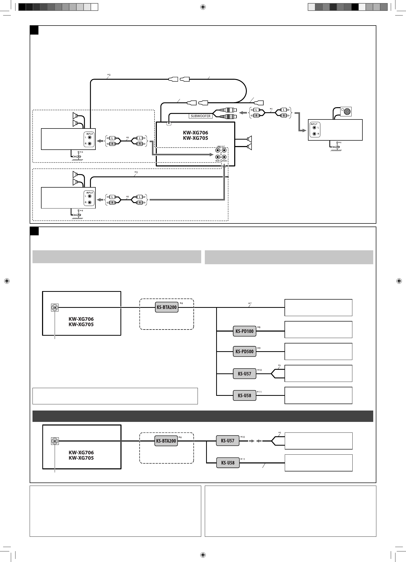
BConnecting the external amplifiers and subwoofer / °“√μËÕ°—∫·Õ¡ª≈‘ø“¬‡ÕÕ√Ï·≈–´—ø«Ÿø‡«Õ√Ïμ—«πÕ°
You can connect amplifiers to upgrade your car stereo system.
• Connect the remote lead (blue with white stripe) to the remote lead of the other equipment so that it
can be controlled through this unit.
• Disconnect the speakers from this unit, connect them to the amplifier. Leave the speaker
leads of this unit unused.
§ÿ≥“¡“√∂μËÕ°—∫·Õ¡æ≈‘ø“¬‡ÕÕ√Ï ‡æ◊ËÕ‡æ‘Ë¡§ÿ≥ ¿“懒¬ß„ÀÈ°—∫√–∫∫‡μÕ√‘‚Õ¢Õß√∂¬πμÏ
• μËÕ“¬μ–°—Ë«√–¬–‰°≈ (’πÈ”‡ß‘π≈“¬¢“«) ‡¢È“°—∫“¬μ–°—Ë«√–¬–‰°≈¢ÕßÕÿª°√≥ÏÕ◊Ëπ Ê ‡æ◊ËÕ®–“¡“√∂§«∫§ÿ¡‚¥¬™ÿ¥ª√–
°Õ∫π’ȉ¥È
• ∂Õ¥≈”‚æßÕÕ°®“°™ÿ¥ª√–°Õ∫π’È ·≈È«μËÕ‡¢È“°—∫‡§√◊ËÕߢ¬“¬ ∑‘Èß“¬μ–°—Ë«≈”‚æߢÕß™ÿ¥ª√–°Õ∫π’ȉ«È
You can connect these components as illustrated below.
• All the components, adapters, or signal cords need to be purchased separately.
CAUTION:
Before connecting the external components, make sure that the unit is turned off.
• To use JVC CD changer, Apple iPod or JVC D. player, set the external input setting to “CHANGER”
(see page 25 of the INSTRUCTIONS).
• To use other external components via KS-U57 or KS-U58, set the external input setting to “EXT IN”
(see page 25 of the INSTRUCTIONS).
∑Ë“π“¡“√∂μËÕÕÿª°√≥Ï¥—ß°≈Ë“«μ“¡¿“淥ߥȓπ≈Ë“ß
• Õÿª°√≥Ï∑ÿ°μ—«√«¡∂÷ßÕ·¥ª‡μÕ√ÏÀ√◊Õ“¬—≠≠“≥μË“ßÊ ®–μÈÕß´◊ÈÕ·¬°μË“ßÀ“°
¢ÈÕ§«√√–«—ß
:
°ËÕπ®–‡™◊ËÕ¡μËÕ°—∫Õÿª°√≥Ï¿“¬πÕ° °√ÿ≥“μ√«®Õ∫„ÀÈ·πË„®«Ë“ªî¥‡§√◊ËÕßÕ¬ŸË
• À“°μÈÕß°“√„™È´’¥’‡™π‡®Õ√Ï¢Õß JVC, Apple iPod À√◊Õ‡§√◊ËÕ߇≈Ëπ JVC D. player „ÀÈμ—Èߧ˓ —≠≠“≥‡¢È“®“°¿“¬πÕ° ‰ª∑’Ë
“CHANGER” (¥ŸÀπÈ“ 25 §”·π–π”)
• À“°μÈÕß°“√μËÕÕÿª°√≥Ï¿“¬πÕ°ºË“π∑“ßÕ·¥ª‡μÕ√á KS-U57 À√◊Õ KS-U58 „ÀÈμ—Èߧ˓ —≠≠“≥‡¢È“®“°¿“¬πÕ° ‰ª∑’Ë “EXT
IN” (¥ŸÀπÈ“ 25 §”·π–π”)
Connecting the external components / °“√μËÕ‡æ‘Ë¡‡μ‘¡‡¢È“°—∫Õÿª°√≥ÏÕ◊ËπÊ
C
Other external component / Õÿª°√≥Ï¿“¬πÕ°Õ◊ËπÊ
3.5 mm stereo mini plug
¢—È«‡’¬∫¡‘π‘‡μÕ√‘‚Õ¢π“¥ 3.5 ¡¡
External component
Õÿª°√≥Ï¿“¬πÕ°
or / À√◊Õ
JVC CD changer
JVC CD ‡™π‡®Õ√Ï
Apple iPod
Apple iPod
JVC D. player
‡§√◊ËÕ߇≈Ëπ JVC D.
CD changer jack
™ËÕ߇’¬∫μËÕ¢Õß ‡§√◊ËÕ߇≈Ëπ CD
or / À√◊Õ
External component
Õÿª°√≥Ï¿“¬πÕ°
or / À√◊Õ
or / À√◊Õ
or / À√◊Õ
External component
Õÿª°√≥Ï¿“¬πÕ°
with or without
¡’À√◊Õ‰¡Ë¡’
*3 Remote lead
*4 Firmly attach the ground wire to the metallic body or to the chassis of the car—to the place uncoated with paint
(if coated with paint, remove the paint before attaching the wire). Failure to do so may cause damage to the
unit.
*5 Signal cord
*6 JVC Bluetooth adapter
*7 Connecting cord supplied for your CD changer
*8 Interface adapter for iPod
*9 D. player interface adapter
*10 Line Input Adapter
*11 AUX Input Adapter
*3 “¬μ–°—Ë«•–¬–‰°•
*4
μËÕ≈«¥
“¬¥‘π„ÀÈ·πËπ‡¢È“°—∫μ—«∂—߇À≈Á° À√◊Õμ—«∂—ß√∂
–
μ√ß
Ë«π ∑’ˉ¡Ë¡’
’‡§≈◊Õ∫ (À“°¡’
’‡§≈◊Õ∫Õ¬ŸË „ÀÈ¢Ÿ¥
’ÕÕ°°ËÕπ °ËÕπμËÕ≈«¥
“¬¥‘π)
À“°‰¡ËªØ‘∫—μ‘μ“¡§”·π–π”π’È ‡§√◊ËÕßÕ“®™”√ÿ¥À√◊Õ‡
’¬À“¬‰¥
*5 “¬‡§‡∫‘≈—≠≠“≥
*6 ∫≈Ÿ∑Ÿ∏Õ·¥ª‡μÕ√Ï¢Õß JVC
*7 μËÕ“¬∑’Ë„ÀÈ¡“”À√—∫ CD ‡™π‡®Õ√Ï
*8 Õ‘π‡μÕ√χøÕ·¥ª‡μÕ√Ï”À√—∫ iPod
*9 Õ‘π‡μÕ√χøÕ·¥ª‡μÕ√Ï”À√—∫ ‡§√◊ËÕ߇≈Ëπ D.
*10 Õ·¥ª‡μÕ√Ï Line Input
*11 Õ·¥ª‡μÕ√Ï AUX Input
CD changer jack
™ËÕ߇’¬∫μËÕ¢Õß ‡§√◊ËÕ߇≈Ëπ CD
with or without
¡’À√◊Õ‰¡Ë¡’
External component
Õÿª°√≥Ï¿“¬πÕ°
Remote lead (blue with white stripe)
“¬μ–°—Ë«•–¬–‰°• (’πÈ”‡ß‘π≈“¬¢“«)
To the remote lead of other equipment or automatic antenna if any
μËÕ“¬°—∫Õÿª°√≥ÏÕ◊ËπÀ√◊Õ‡“Õ“°“»Õ—μ‚π¡—μ‘∂È“¡’
Front speakers
≈”‚æßÀπÈ“
JVC Amplifier
‡§√◊ËÕߢ¬“¬‡’¬ß JVC
Rear speakers
≈”‚æßÀ≈—ß
Y-connector (not supplied for this unit)
¢ÈÕμËÕ√Ÿªμ—« Y (‰¡Ë‰¥È„ÀÈ¡“°—∫™ÿ¥ª√–°Õ∫π’È)
Subwoofer
´—∫«Ÿø‡øÕ√Ï
JVC Amplifier
‡§√◊ËÕߢ¬“¬‡’¬ß JVC
Front speakers
≈”‚æßÀπÈ“
JVC Amplifier
‡§√◊ËÕߢ¬“¬‡’¬ß JVC
iPod is a trademark of Apple Inc., registered in the U.S. and other countries.
iPod ‡ªÁπ‡§√◊ËÕßÀ¡“¬°“√§È“¢Õß Apple Inc. ´÷Ëß®¥∑–‡∫’¬π°“√§È“„πª√–‡∑»À√—∞Õ‡¡√‘°“·≈–ª√–‡∑»Õ◊ËπÊ
Install2_KW-XG706_009A_2.indd 4Install2_KW-XG706_009A_2.indd 4 4/13/07 2:47:17 PM4/13/07 2:47:17 PM
