JVC Compact Disc Manual L0080096
User Manual: JVC JVC Compact Disc Manual JVC Compact Disc Owner's Manual, JVC Compact Disc installation guides
Open the PDF directly: View PDF ![]() .
.
Page Count: 16
/I/I///////
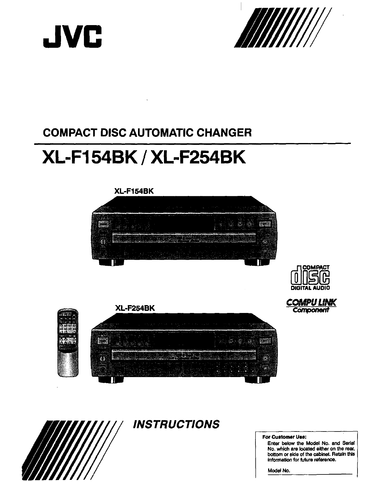
COMPACT DISC AUTOMATIC CHANGER
XL-F154BK /XL-F254BK
XL-F154BK
DIGITAL AUDIO
XL-F254BK C_%fPULINK
For CuStomer Use:
Enter below the Model No. and 8edal
No. wh'_hare located eitheron the re_,
bottomorsideof the cabinet.Retainthis
Informationfor futurereference.
Model No.
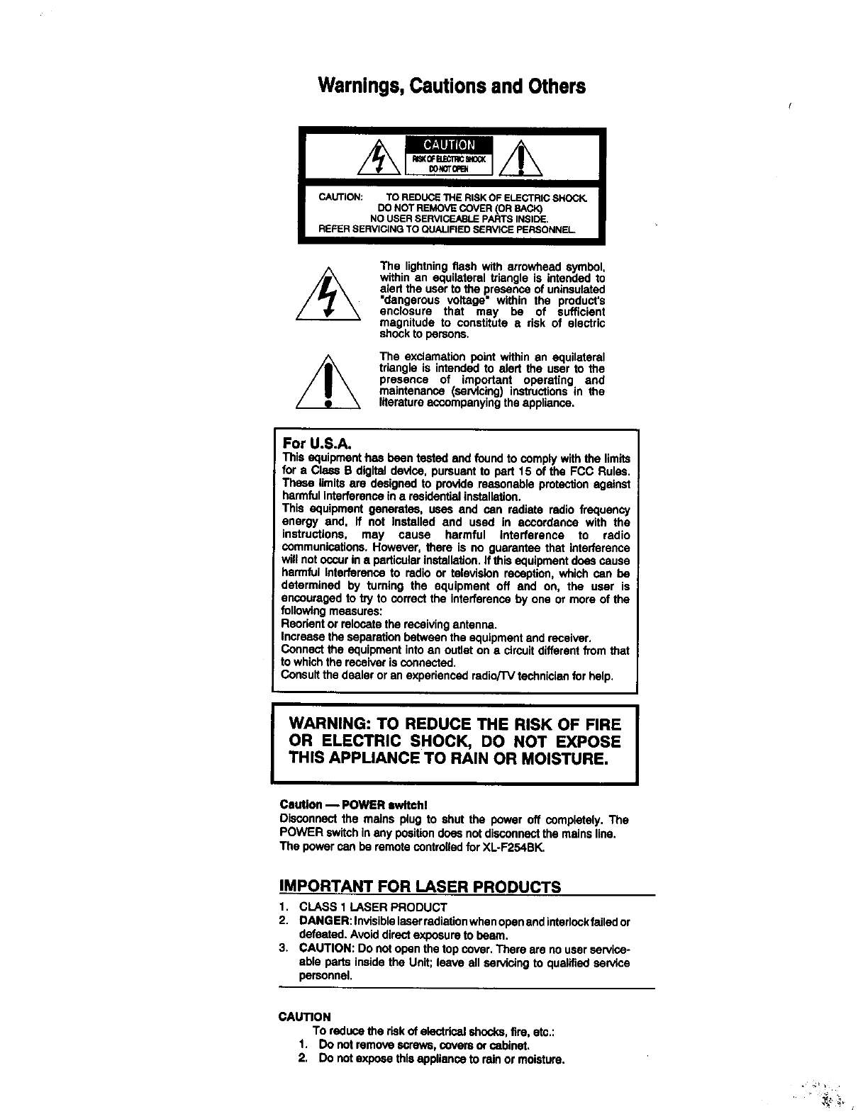
Warnings, Cautions and Others
CAUTION: TO REDUCE 1HE RISK OF ELECTRIC SHOCK.
DO NOT REMOVE DOVER (OR BACK)
NO USER SERVICEABLE PARTS INSIDE.
REFER SERVICING TO QUALIFIED SERVICE PERSONNEL•
The lightning flash with arrowhead symbol,
within an equilateral triangle is intended to
alert the user to the presence of uninsutsted
"dangerous voltage" within the product's
enclosure that may be of sufficient
magnitude to constitute arisk of electric
shock to persons.
The exclamationpoint withinan equilateral
triangleis intendedto alert the user to the
presence of important operating and
maintenance (servicing)instructionsin the
literatureaccompanying the appliance.
For U.S.A.
This equipment has been tested and foundto complywith the limits
for a Class B digital devise, pursuantto pert 15 of the FCC Rules.
These limitsare designedto providereasonableprotectionagainst
harmfulinterferencein a residentialinstallation,
This equipment generates, uses and can radiate radio frequency
energy and. if not installed and used in accordance with the
instructions, may cause harmful interference to radio
communications.However, there is no guarantee that interference
willnotoccurin aparticularinstallation.Ifthis equipment doas cause
harmful interferenceto radio or televisionreception,which can be
determined by turning the equipment off and on, the user is
encouragedto try to correctthe interferenceby one or more of the
followingmeasures:
Reorientor relocatethereceivingantenna.
Increasetheseparationbetween theequipment and receiver.
Connectthe equipment into an outleton a circuitdifferentfrom that
to whichthe receiveris connected.
Consultthe dealer or an experiencedradio/TVtechnicianfor help.
IWARNING: TO REDUCE THE RISK OF FIRE
OR ELECTRIC SHOCK, DO NOT EXPOSE
THIS APPLIANCE TO RAIN OR MOISTURE,
Caution _POWER awltoh!
Disconnectthe mains plug to shut the power off completely.The
POWER switchIn any poaitiondoes notdisconnectthe mainsline.
The power can be remotecontroUedfor XL-F254BK.
I
IMPORTANT FOR LASER PRODUCTS
1. CLASS 1 LASER PRODUCT
2. DANGER: Invleiblelaserradletionwhecopenand intarlockfailedor
defeated.Avoiddirectexposureto beam.
3. CAUTION: Do not openthetop cover. There are no userservice-
able parts insidethe Unit;leave all servicing to qualifiedservice
personnel.
CAUTION
To reducethe riskof electricalshocks,fire, etc.:
1. Do notremove screws,coversof cabinet.
2. Do notexpose thisapplianceto rain or moisture.
We would like to thank you forpurchasing one of ourJVC
products.
Before connecting this unit to the wall outlet, please read
the instructions carefully to ensure that you obtain the
best possible performance.
ff you have any questions, please consult your JVC
dealer.
|
Table of contents
INTRODUCTION ................................................ 1
Precautions ................................................................. 1
About this manual ....................................................... 1
Names of buttons ........................................................ 2
BEFORE USING FOR THE FIRST TIME .......... 4
Installing the unit ......................................................... 4
Connecting to other equipments ................................ 4
Supplying the power .................................................. 5
To connectthe AC power cordof the mainunit ............ 5
To installthe batteries in the remotecontrolunit
(for XL-F254BK).............................................................. 5
COMPU LINK connection ......................................................6
BASIC OPERATIONS ....................................... 7
Basic functions for disc playback ............................... 7
Turningon the power ofthis unit.................................... 7
Loadingdiscsinthe disctray ........................................ 7
Remotecontroloperation (forXL-F254BK) .................... 7
Playing a disc ................................................................. 7
Stopping playback ......................................................... 7
Locating a point to start playback .............................. 8
Skipping to a desired disc ............................................. 8
Skipping to a desired track ............................................ 8
Searching for a desired section ..................................... 8
Specifying a desired disc .............................................. 8
Specifying a desired track (for XL-F254BK) .................. 8
Changing discs during playback ................................ 9
VARIOUS PLAYBACK PA'n'ERNS ................. 9
Playing tracks in a order of track/disc number ........... 9
Playing tracks in a desired order .............................. 10
Playing tracks in arandom order .............................. 11
Playing repeatedly .................................................... 11
Repeating all discs ....................................................... 11
Repeating one track ..................................................... 11
GENERAL INFORMATIONS ........................... 12
COMPU LINK remote control system ....................... 12
Care and handling .................................................... 13
Troubleshooting ........................................................ 14
Specifications ............................................................ 14
INTRODUCTION
Precautions
Load compact discs only
Never insertanything otherthancompact discs intoany part of the
player,
If a problem persists
Ifsomething goes wrong,turn off the power immediately. If thesame
problem reoccurs when the power is turned on once more, turn off the
power again and consult your JVC dealer.
Handling the power cord
When unpluggingfromthe wall socket, alwayspull the plug body,
neverthe power cable.
Volume settings
A CD player has a_mostzero background noise. Because of this, the
technique of listening to the background level and then setting the
volume before the music starts, as used with analog tumtables or tape
decks, cannot be used. If you raise the volume level too high, speaker
damage may result.
Condensation
The CD player uses opticalcomponents. If it is moved from a cold
location to a warm one, or is used in a room subjectto excessive
humidityorwhere a fire has justbeen lit,condensationcouldform on
theoptical components.
This may preventthelaser beam from being properlytransmittedand
thuscauses noiseor evenamalfunction.
If condensationhas formed and the CD player does not function
correctly,we recommendthatyouleaveitturnedonfor an hourortwo.
If atthe end ofthistimetheCD player stilldoes notfunction properly,
please consultyour JVC dealer.
Transporting the unit
When carryingthisunit,it is best to avoideithertiltingit or turningit
upside-down.Where you cannotavoid doing so, pleaseremove the
discs first.
Using compact discs
Compact discs aremadeofplasticandcan easilybe damaged. Ifthe
disc is dirty, scratched, warped or otherwise damaged, the digital
informationmay not be picked up correctly.
Applicable dlsca
Thisunitcan onlybe usedwithcompactdiscs bearing the markbelow.
Neverusediscs of othertypes.
About this manual
This manual covers the operating instructions for the compact disc
automatic changers XL:-F254BK and XL-F154BK.
There are several functions which require separate instructions for
each model, Please check the model number stated on the carton box
and follow the descriptions applicable to your unit,
Especially, please note that the remote control unit RM-SX254U is
supplied only with XLoF254BK. For XL-F154BK, ignore all the de-
scriptions on the remote control unit.
This manual is organized as follows:
The first part, "INTRODUCTION", gives you the precautions when
using this unit, and showsyou the names of buttons on the main unit
and the remote control unit.
The second part, "BEFORE USING FOR THE FIRST TIME", tells you
what kind of operations you should do before playing discs, This part
describes where to place the unit for best results, how to install
batteries in the remote control unit and how to connect this unit to the
amplifier/receiver and other components.
The third part, "BASIC OPERATIONS",describes how to load discs,
and convenient basic functions for playingdiscs.
The fourth part, "VARIOUS PLAYBACKPATFERNS",describes vari-
ous functions for playing discs, and convenient functions for record-
ing.
The fifth part, "GENERALINFORMATIONS",describesthe COMPU
LINK remotecontrolsystemwhich facilitatesvariousoperationsbe-
tweenJVC components,and explainshowto take care of discs.
Thispartalsoincludes=Troubleshooting",whichtellsyouhow tocheck
the unitwhen a malfunctionoccurs, and the technical informations
regardingthis unit.
DIOITALAUDIO
INTRODUCTION
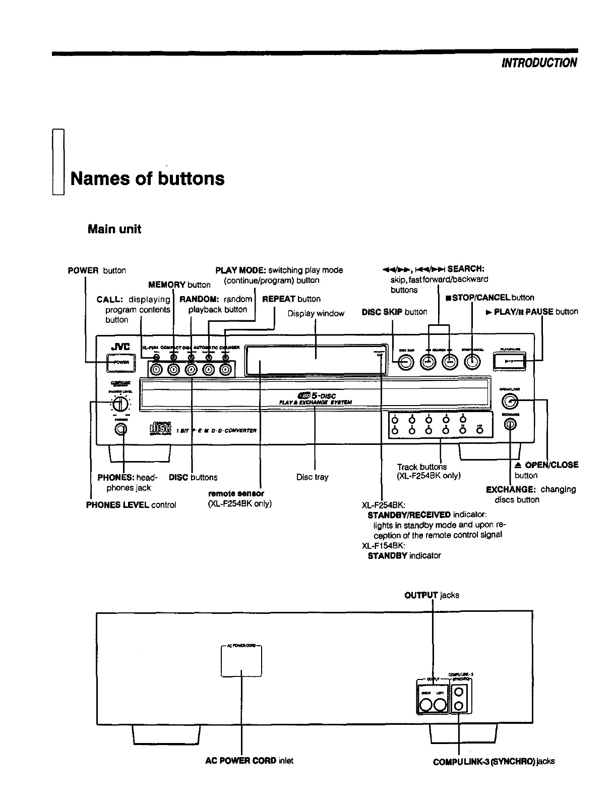
_Names of buttons
Main unit
POWER button
MEMORY button
CALL: displaying
program contents
button
PLAY MODE: switchingplay mode
(continue/program)button
RANDOM: randomIREPEAT button
playbackb.._._ I Displaywindow
_5"D_SC
PLAy&EXCHANGE $yS"LF..M
.<</_, f.4Z<!_HHSEARCH:
skip,fastforward/backward
buttons • STOP/CANCEL button
DISC SKIP button I_ PLAY/II PAUSE button
O
Track bu_ons !OPEN/CLOSE
PHONES: head- DISC buttons
phones jack remote lenlor
PHONES LEVEL control (XL-F254BK only)
Disctray (XL-F254BKonly) button
EXCHANGE: changing
discs button
XL-F254BK:
STANDBY/RECEIVED indicator:
lightsin standbymode and upon re-
ceptionof the remote controlsignal
XL.Ft54BK:
STANDBY indicator
OUTPUT jacks
3
AC POWER CORD inlet COMPUUNK-3 (SYNCHRO)jacks
INTRODUCTION
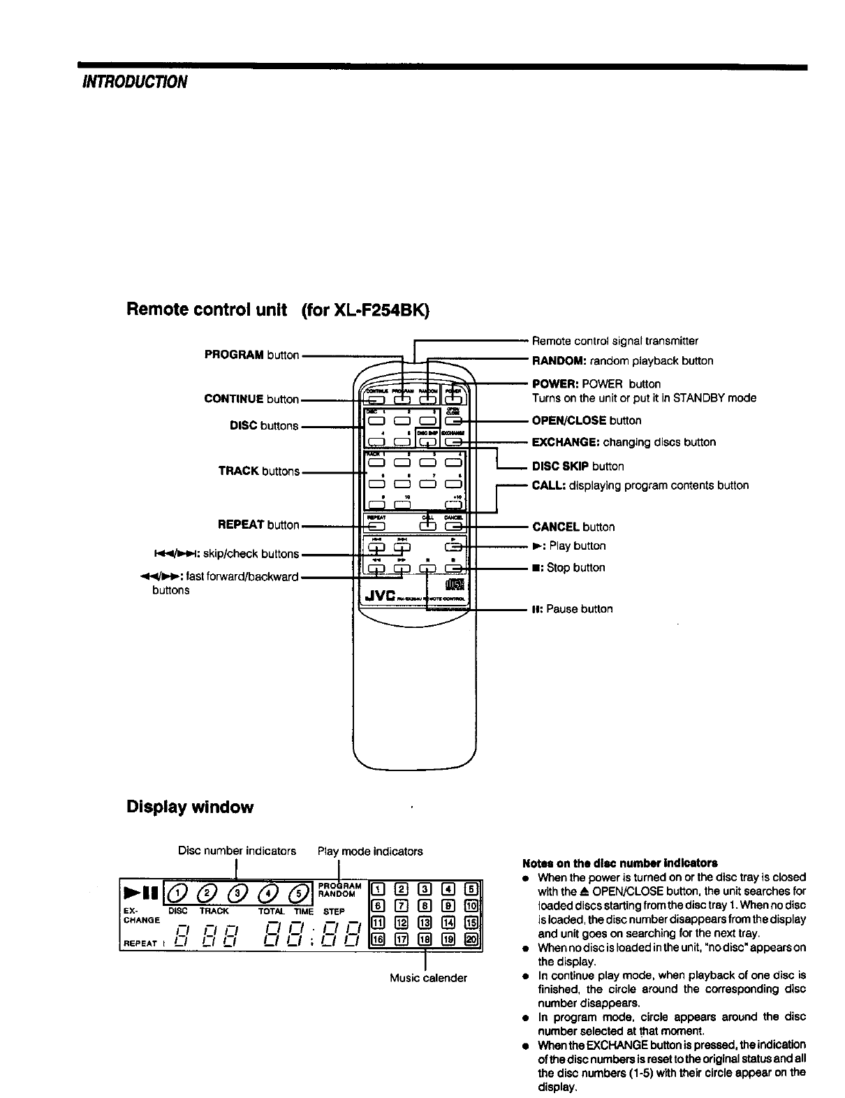
Remote control unit (for XL-F254BK)
PROGRAM button
CONTINUE button
DISC buttons
TRACK buttons--
REPEAT button_
I<<hHH: skip/checkbuttons
'<4/=H_:fastforward/baokward
buttons
0 t0 ,,,e
JVC.--._..-_
Remote control signal transmitter
RANDOM: random playback button
POWER: POWER button
Turns on the unit or put it in STANDBY mode
-- OPEN/CLOSE button
EXCHANGE: changing discs button
_- DISC SKIP button
yCALL: displaying program contents button
CANCEL button
I,_: Play button
-- I1: Stop button
I1: Pause button
Display window
Disc number indicators Play mode indicators
EX- DiSC TRACK TOTAL TIME STEP
CHANGE nFlO FIFI.FIFI
._'EA'r t I----/ L.-I LI I--I I_-I ,I__1 LI
Music calender
Notes on the disc number Indloator=
a Whenthe power is turnedon orthe disc tray isclosed
withthe AOPEN/CLOSEbutton,theunitsearchesfor
loadeddiscsstartingfromthedisctray 1.When nodisc
isloaded,thediscnumberdisappearsfromthedisplay
end unitgoes on searchingfor the nexttray.
• Whennodiscisloadedintheunit,"nodisc"appearson
thedisplay.
•In continueplaymode, when playback of one disc is
finished, the circle around the correspondingdisc
number disappears.
•In program mode, circle appears around the disc
numberselectedat that moment.
a WhectheEXCHANGEbuttonispressed,theindication
of thediscnumbersisresettotheoriginalstatusendall
the disc numbers(1-5) withtheir circleappear on the
display.
BEFOREUSINGFORTHEFIRSTTIME
_Connecting to other
Installing the unit equipments
Best location
Select a locationwhich is level,dry and neither too cold nor too hot
(temperature range 5°C (41°F) to 35°C (95°F)). Also, avoid dusty
locations or any location subjectto vibration,
If Interference occurs
if this unit is placed near a tuner or a radio receiver tuned to AM
frequencies, interference mayoccur. If this happens, we recommend
either that you move this unit as far away as possible from the tuner or
receiver or briefly turn off the power to this unit.
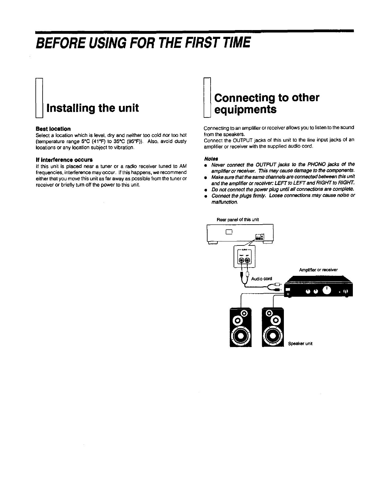
Connecting to an amplifier or receiver allows you to listen to the sound
from the speakers.
Connect the OUTPUT jacks of this unit to the line input jacks of an
amplifier or receiver with the supplied audio cord.
Notes
•Never connect the OUTPUT jacks to the PHONO jacks of the
amplifier or receiver, This may cause damage to the components.
•Makesurethstthesemechannelsereconnectedbetweenthisunit
and the amplifier or receiver: LEFT to LEFT and RIGHT to RIGHT.
•Do not connect the power plug untilall connections are complete.
•Connect the plugs firmly. Loose connections may cause noise or
malfunction.
Rear panelof this unit
'Audiocord
Amplff'mrorreceiver
Speakerunit
I ill IIII
BEFOREUSING FOR THE FIRST TIME
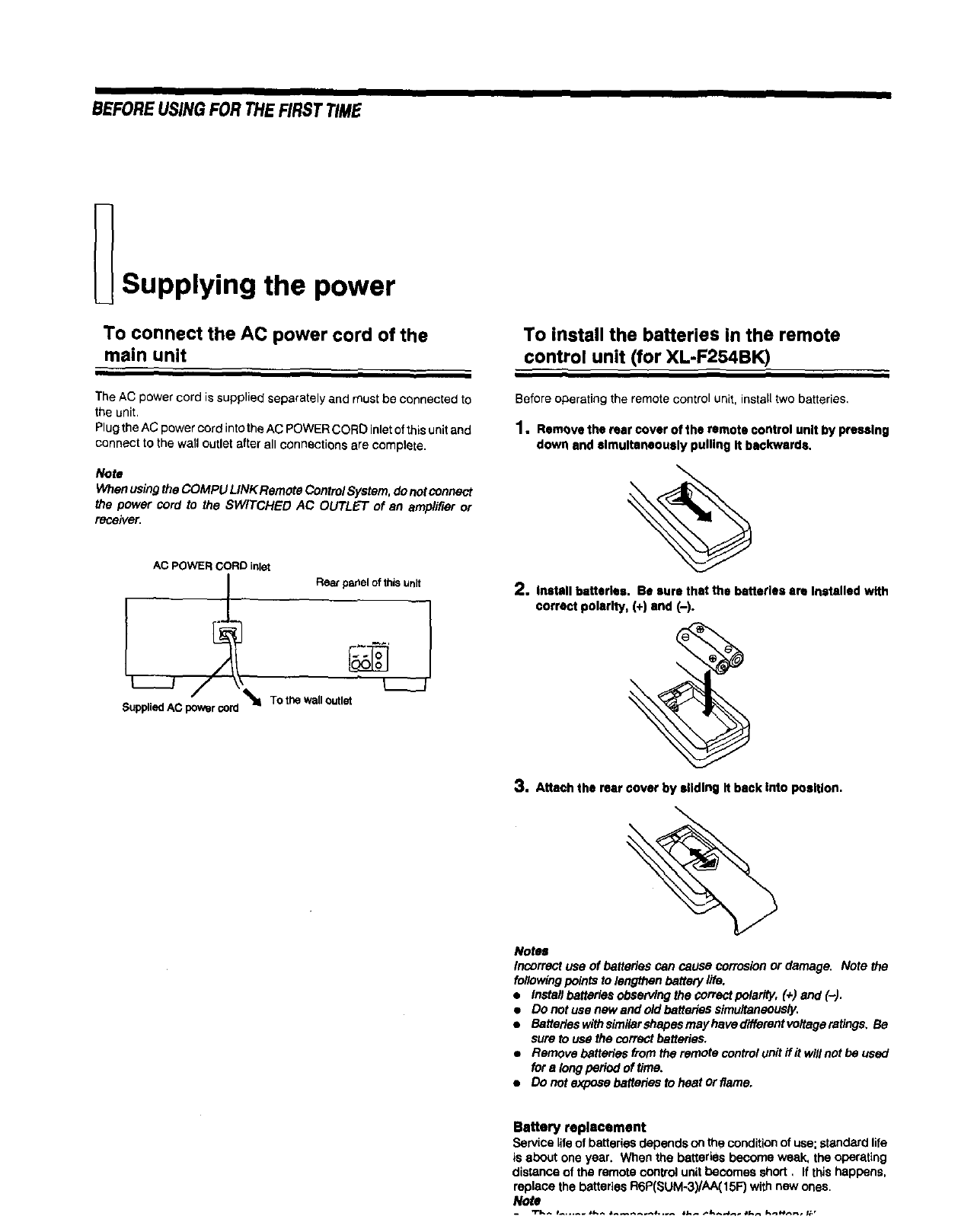
Supplying the power
To connect the AC power cord of the
main unit
TheAC power cord is suppliedseparatelyand must be connected to
the unit.
Plugthe AC power cord into theAC POWERCORD inletof this unitand
connect to the wall outlet after all connections are complete.
Note
When using the COMPU LINK Remote ControI System, do not connect
the power cord to the SWITCHED AC OUTLET of an amplifier or
receiver.
AC POWER CORE)inlet
_.oo^upp"-J AC powsrcord To the walloutlet
To install the batteries in the remote
control unit (for XL-F254BK)
Before operating the remote control unit, install two batteries,
1, Remeve the rear cover of the remote control unit by pressing
down and simultaneously pulling it backwards.
2, install batteries. Be sure that the batteries are installed with
correct pctarlty, (+) and (-).
\
3. Attach the rear cover by sliding It back Into position.
Notes
Incorrect use of batteries can cause corrosion or damage. Note the
following points to lengthen battery life.
•Install batteries observing the correct polarity, (+) and (-).
•Do not use new and old batteries simultaneously.
•Batteries with similarshapes mayhave different voltage ratings, Be
sure to use the correct batteries.
•Remove batteries from the remote control unit flit will not be used
for a long period of time,
•Do not expose batteries to heat or flame.
Battery replacement
Service life of batteries depends on the condition of use; standard life
is about one year. When the batteries become weak, the operating
distance of the remote centro_ unit becomes short, If this happens,
replace the batteries R6P(SUM-3yAA(15F) with new ones.
Note
COMPU LINK connection
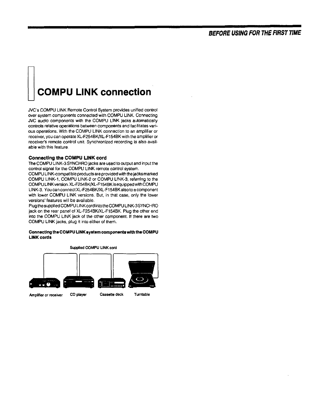
JVC's COMPU LINK Remote Control System provides unified control
over system components connected with COMPU LINK. Connecting
JVC audio components with the COMPU LINK jacks automatically
controls relative operations between components and facilitates vari-
ous operations. With the COMPU LINK connection to an amplifier or
receiver, you can operate XL-F254BK]XL-F154BK with the amplifier or
receiver's remote control unit. Synchronized recording is also avail-
able with this feature.
Connecting the COMPU UNK cord
The COMPU LINK-3 SYNCHRO jacks are used to output and input the
control signal for the COMPU LINK remote control system,
COMPU LINK-compatible prod ucts are provided with the jacks marked
COMPU LINK-l, COMPU LINK-2 or COMPU LINK-3, referring to the
COMPU LINK version, XL-F254BK/XL-F154BK isequipped with COMPU
LINK-3, You can connect XL-F254BK/XL-F154BK also to a component
with lower COMPU LINK versions, But, in that case, only the lower
versions' features will be available,
Plug the supplied COMPU LINK cord into the COMPU LINK-3 SYNCH RO
jack on the rear panel of XL-F254BK/XL-F154BK. Plug the other end
into the COMPU LINK jack of the other component. If there are two
COMPU LINK jacks, plug it into either of them.
Connectingthe COMPU LINKsystemcomponents withtheCOMPU
LINK cords
SuppliedCOMPU LINKcord
Amplifier or receiver CO prayer Cass_ed_k Turntable
BEFORE USINGFOR THEFIRST TIME
BASICOPERATIONS
Basic functions for disc
playback
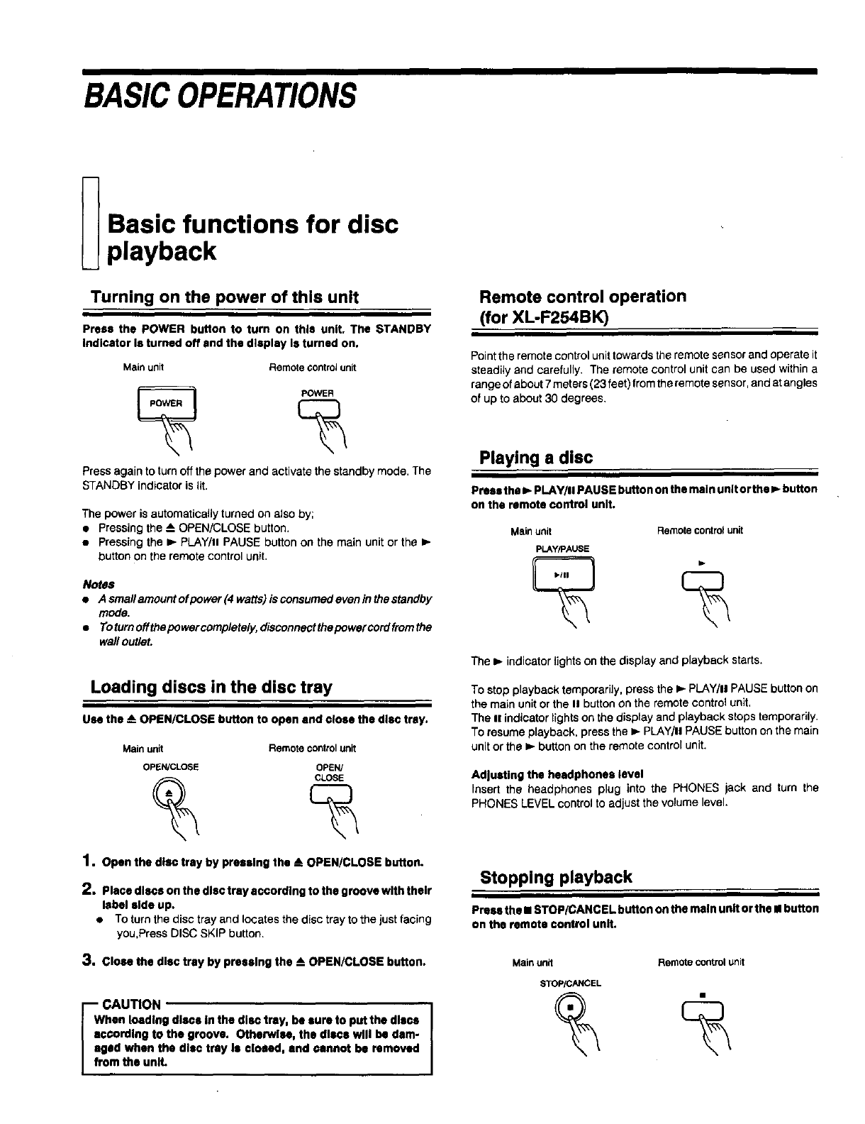
Turning on the power of this unit
Press the POWER button to turn on this unit. The STANDBY
indicator Is turned off and the display Is turned on.
Mainunit Remotecontrolunit
Press againto turn offthe power and activate thestandbymode. The
STANDBYindicator is lit,
The power is automatically turned on also by;
•Pressing the -- OPEN/CLOSE button,
•Pressing the I_- PLAY/. PAUSE button on the main unit or the I_-
button on the remote control unit.
Notes
•Asmallamountofpower(4watts)isconsumedeveninthestandby
mode,
•Toturnoffthepowercompletely, disconnectthepowercordfromthe
wall outlet.
Loading discs in the disc tray
Use the AOPEN/CLOSE button to open end close the disc tray.
Main unit Remote controlunit
OPE_N/CLOSE OPEN/
1. open the disc tray by pressing the AOPEN/CLOSE button.
2, Placediscsonthedisctraysccordingtothegroovewiththeir
label side up.
•TO turn the disc tray and locates the disc tray to the just facing
you,Press DISC SKIP button.
3. Close the disc tray by preselng the AOPEN/CLOSE button.
Iaa_CAUTION
hen loading discs In the disc tray, be lure to put the discs
c¢ordlng to the groove, Otherwise, the discs will be dam-
sad when the disc tray Is closed, end cannot be removed
mthe unlL
Remote control operation
(for XL-F254BK)
Point the remote control unit towards the remote sensor and operate it
steadily and carefully. The remote control unit can be used within a
range of about 7 meters (23 feet) from the remote sensor, and at angles
of up to about 30 degrees,
Playing a disc
Press the I_ PLAY/II PAUSE button on the main unit or the I,, button
on the remote control unit.
Mainunit Remotecontrolunit
pLAY/PAUSE
The ib indicator lights on the display and playback starts.
To stop playback temporarily, press the I,,-PLAY/II PAUSE button on
the main unit or the II button on the remote control unit.
The uindicator lights on the display and playback stops temporarily.
To resume playback, press the )- PLAY/II PAUSE button on the main
unit or the _- button on the remote control unit.
Adjusting the headphones level
Insert the headphones plug into the PHONES jack and turn the
PHONES LEVEL control to adjust the volume level.
Stopping playback
Press the •STOP/CANCEL button on the main unit or the •button
on the remote control unit.
Mainunit Remotecontrolunit
STOPiCANCEL
BASIC OPERATIONS
Locating a point to start
playback
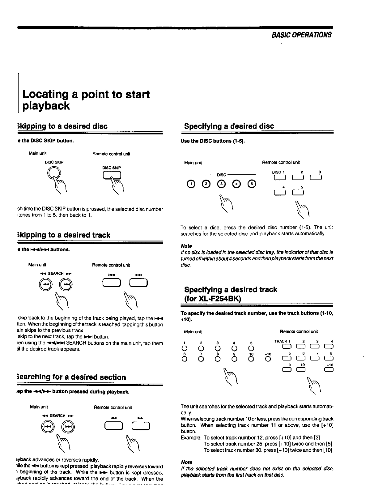
)kipping to a desired disc
• the DiSC SKIP button.
Main unit Remote control unit
DISC SKIP
DISC_SKIP
3h time the DISC SKIP button is pressed, the selected disc number
itches from 1 to 5, then back to 1.
;kipping to a desired track
s the I<1</_1 buttons.
Main unit Remote control unit
._ SEARCH
®®
skip back to the beginning of the track being played, tap the P<.<
tton. When the beginning of the trackis reached, tapping this button
ain skips to the previous track.
skip to the next track, tap the _ button.
]en using the I_IHH SEARCH buttons on the main unit, tap them
_ilthe desired track appears.
;earching for a desired section
,ep the <</=,'_ button pressed during playback.
Main unit Remote control unit
SEARCH
lyback advances or reverses rapidly.
1lie the .q_ button is kept pressed, playback rapidly reverses toward
_. beginning of the track. While the _button is kept pressed,
*yback rapidly advances toward the end of the track. When the
Specifying a desired disc
Use the DiSC buttons (1-5).
Main unit Remote control unit
DiSC 12
DiSC (Z_
QQ®®® , °
r-7
To select a disc, press the desired disc number (1-5). The unit
searches for the selected disc and playback starts automatically.
Note
If no disc is loaded in the selected disc tray, the indicator of that disc is
turned off within about 4 seconds and then playback starts from the next
disc,
Specifying a desired track
(for XL-F254BK)
To specify the desired track number, use the track buttons (1-10,
+10).
Main unit Remote controlunit
1 2 3 4 5 TRACK 1 2 3 4
0 0 0 0 0 c_ c:3 _ c_
6 7 8 9 10 +10 5 6 7 8
0 0 0 0 0 0 r-7 r7 _ c3
8 10 +10
Theunitsearchesforthe selectedtrack and playback startsautomati-
cally.
Whenselecting track number 10or less. press thecorresponding track
button. When selecting track number 11 or above, use the [+10]
button.
Example: To select track number 12, press[+10] and then[2].
To select tracknumber25, press[+10] twice and then [5].
Toselecttracknumber30, press[+10] twice and then [10].
Note
ff the selected track number does not exist on the selected disc,
playbackstartsfromthe firsttrackon that disc.
II
GENERALINFORMATIONS
Care and handling
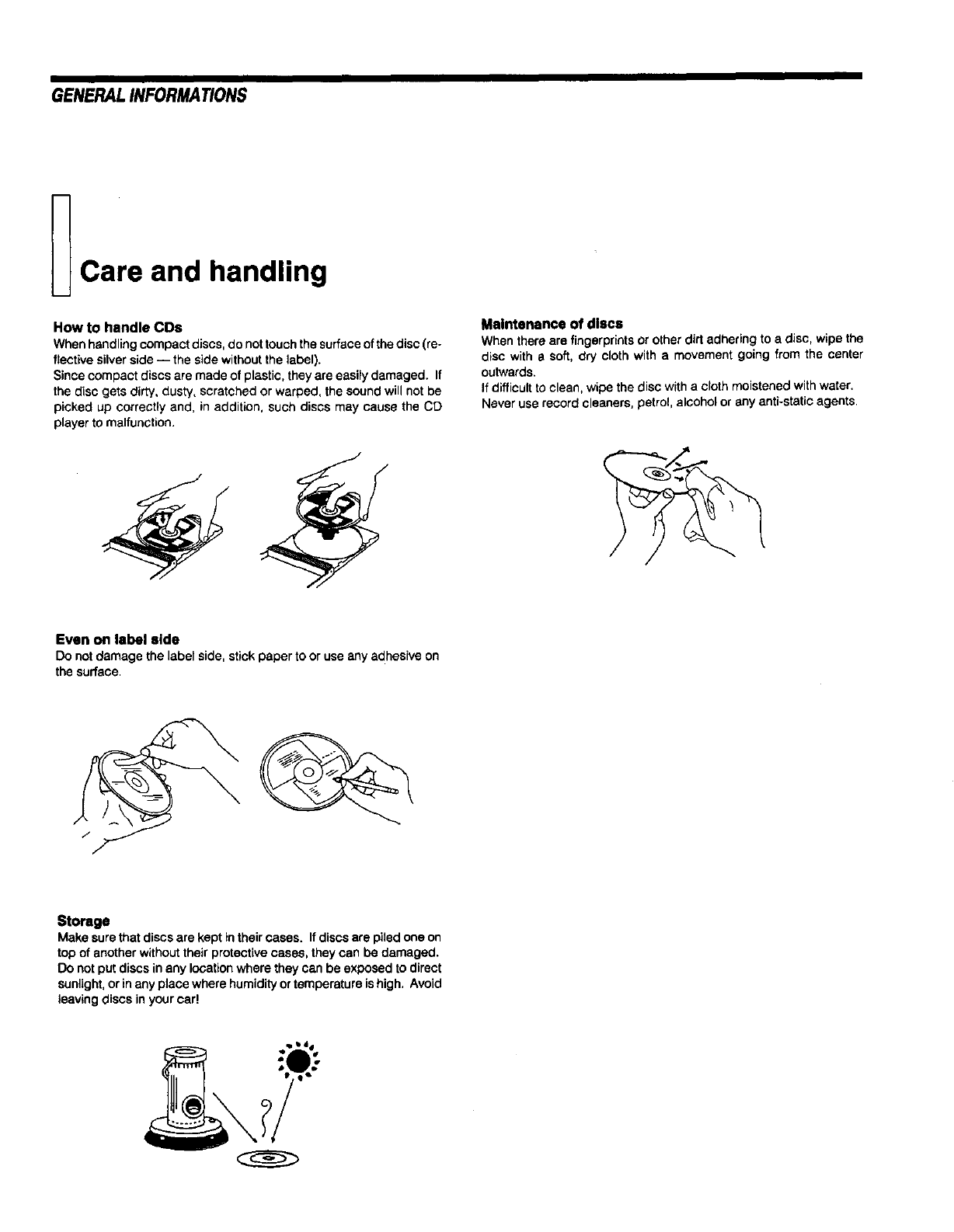
How to handle COs
When handling compact discs, do not touch the surface of the disc (re-
flective silver side -- the side without the label).
Since compact discs are made of plastic, they are easily damaged. If
the disc gets dirty, dusty, scratched or warped, the sound will not be
picked up correctly and, in addition, such discs may cause the CD
player to malfunction,
Maintenance of discs
When there are fingerprints or other dirt adhering to a disc, wipe the
disc with 8 soft, dry cloth with a movement going from the center
outwards.
If difficult to clean, wipe the disc with a cloth moistened with water.
Never use record cleaners, petrol, alcohol or any anti-static agents.
Even on label side
Do notdamage the label side, stickpaper to or useany adhesive on
the surface.
Storage
Make surethat discsare kept intheircases. If discsare piledone on
topof anotherwithouttheir protectivecases, theycan be damaged.
Do not putdiscs inany locationwhere they can be exposedto direct
sunlight,orinany place wherehumidityortemperatureishigh. Avoid
leaving discs inyourcar!
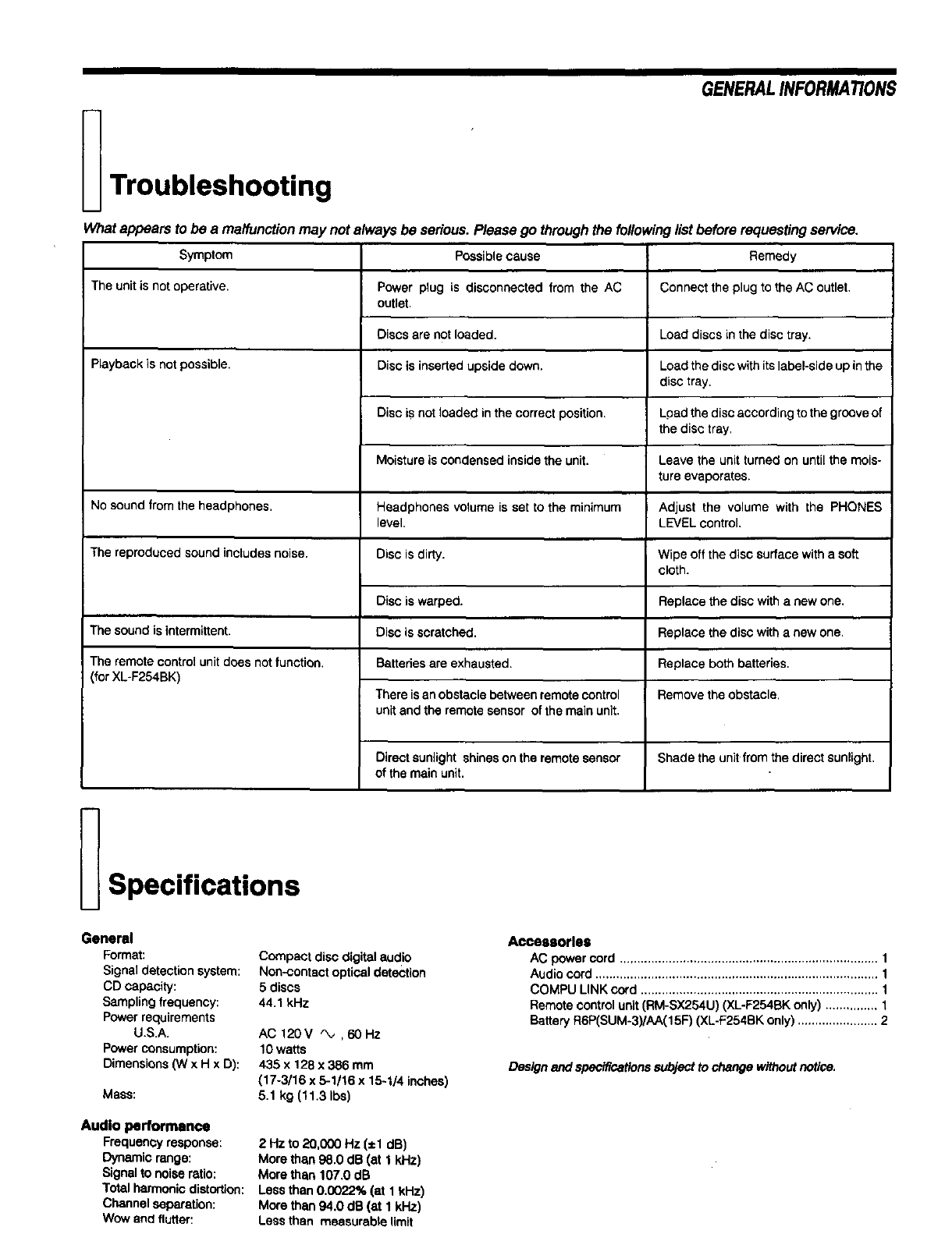
Troubleshooting
What appears to be a malfunction may not always be serious. Please go through the followir
Symptom Possiblecause
The unitis not operative. Power plug is disconnected from the AC
outlet.
Discs are notloaded.
Playbackis notpossible. Disc is insertedupside down,
GENERALINFORMATIONS
No sound from the headphones.
The reproduced sound includes noise.
The sound is intermittent.
The remote control unit does not function.
(for XL-F254BK)
Disc is not loaded in the correct position.
Moisture is condensed inside the unit.
Headphones volume is set to the minimum
level.
Disc is dirty.
Disc is warped.
Disc is scratched.
Batteries are exhausted.
There is an obstacle between remote control
unit and the remote sensor of the main unit.
rlist before requesting service,
Remedy
Connect the plug to the AC outlet,
Load discs in the disc tray.
Load the disc with its label-side up in the
disc tray.
Load the disc according to the groove of
the disc tray.
Leave the unit turned on until the mois-
ture evaporates,
Adjust the volume with the PHONES
LEVEL control,
Wipe off the disc surface with a soft
cloth.
Replace the disc with a new one.
Replace the disc with a new one.
Replace both batteries.
Remove the obstacle.
Directsunlight shineson the remotesensor Shade the unit fromthe direct sunlight.
of the mainunit,
Specifications
General
Format:
Signal detection system:
CD capacity:
Sampling frequency:
Power requirements
U.S.A.
Power consumption:
Dimensions (W x H x D):
Mass:
Audio performance
Frequencyresponse:
Dynamicrange:
Signalto noiseratio:
Totalharmonicdistortion:
Channelseparation:
Wow and flutter:
Compact disc digital audio
Non-contact optical detection
5 discs
44.1 kHz
AC 120V _, ,60Hz
10 watts
435x 128 x 386 mm
(17-3/16 x 5-1/16 x 15-1/4 inches)
5.1 kg (11.3 Ibs)
2 Hz to 20,000 Hz (±1 dB)
More than98.0 dB (at 1 kHz)
More than 107.0 dB
Less than0.0022% (at I kHz)
More than 94.0 dB (at 1 kHz)
Less than measurable limit
Acceaaortaa
AC power cord .......................................................................... 1
Audio cord ................................................................................. 1
COMPU LINK cord .................................................................... 1
Remote control unit (RM-SX254U) (XL-F254BK only) ............... 1
Battery R6P(SUM-3)/AA(15F] (XL-F254BK only) ....................... 2
Designandspecificationssubjectto changewithoutnotice.
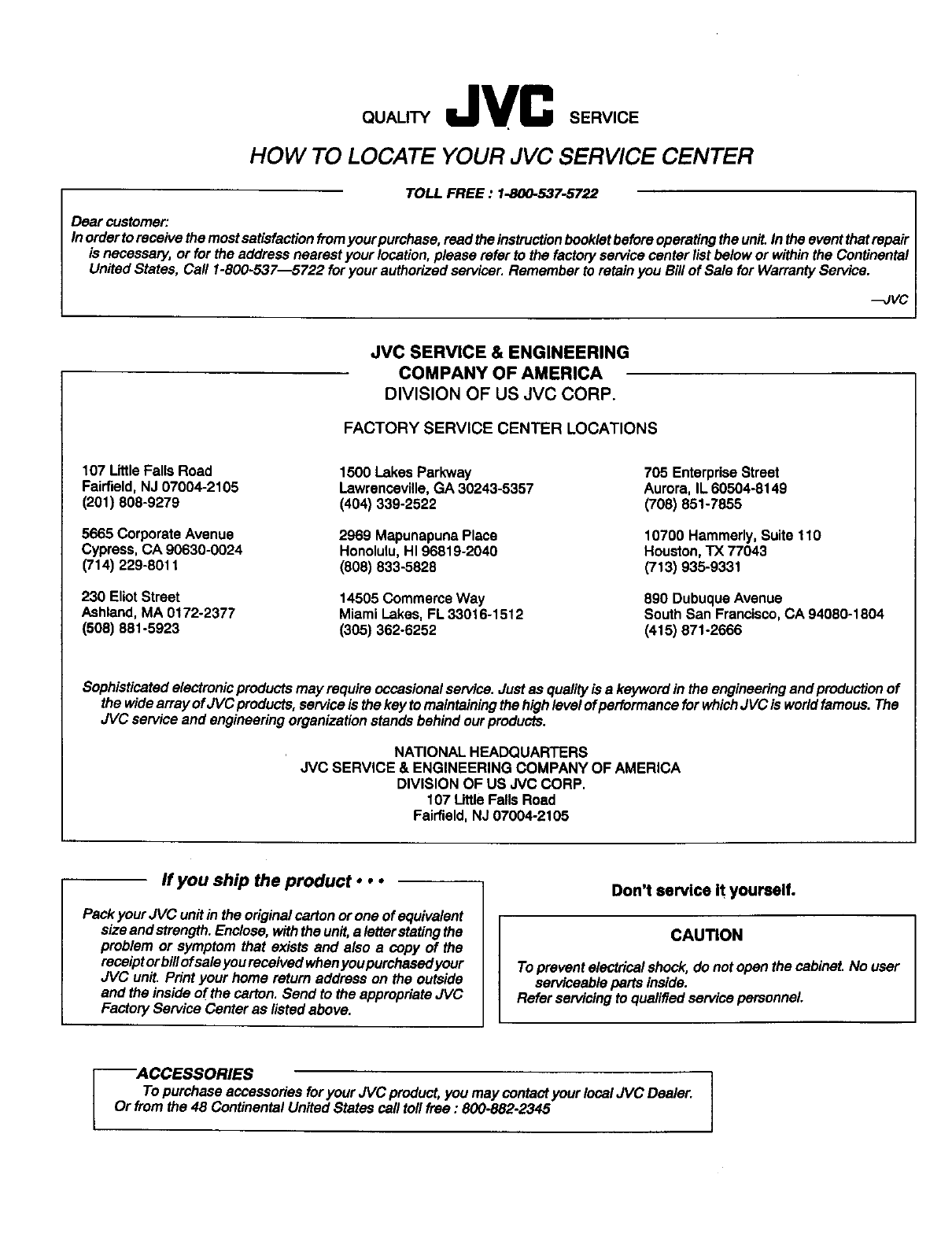
HOW TO LOCATE YOUR JVC SERVICE CENTER
TOLL FREE:1-800-537_722
Dear customer:
In order to receive the most satisfaction fromyour purchase, read the instruction booklet before operating the unit. In the event that repair
is necessary, or for the address nearest your location, please refer to the factory service center list below or within the Continental
United States, Call 1-800-537---5722 for your authorized servicer. Remember to retain you Bill of Sale for Warranty Service.
--JVC
JVC SERVICE & ENGINEERING
COMPANY OF AMERICA
DIVISION OF US JVC CORP.
FACTORY SERVICE CENTER LOCATIONS
107 Little Falls Road
Fairfield, NJ 07004-2105
(201) 808-9279
5665 Corporate Avenue
Cypress, CA 90630-8024
(714) 229-8011
230 Eliot Street
Ashland, MA 0! 72-2377
(508) 881-5923
1500 Lakes Parkway
Lawrenceville, GA 30243-5357
(404) 339-2522
2969 Mapunapuna Place
Honolulu, HI 96819-2040
(808) 833-5828
14505 Commerce Way
Miami Lakes, FL 33016-1512
(305) 362-6252
705 Enterprise Street
Aurora, IL 60504-8149
(708) 351-7855
10700 Hammerly, Suite 1t 0
Houston, TX 77043
(713) 935-9331
890 Dubuque Avenue
South San Francisco, CA 94080-1804
(415) 871-2666
Sophisticatedelectronicproductsmay requireoccasionalservice.Justas qualityis a keywordin the engineeringandproductionof
the wide arrayofJVC products,serviceis thekeyto maintainingthehighlevelofperformance for whichJVC is worldfamous.The
JVC serviceand engineeringorganizationstandsbehindourproducts.
NATIONAL HEADQUARTERS
JVC SERVICE & ENGINEERING COMPANY OF AMERICA
DIVISION OF US JVC CORP,
107 LittleFallsRoad
Fairfield,NJ 07004-2105
ff you ship the product • ••
Pack your JVC unit in the original carton or one of equivalent
size and strength. Enclose, with the unit, a letter stating the
problem or symptom that exists and also a copy of the
receipt or billof sale you received when you purchased your
JVC unit. Print your home return address on the outside
and the inside of the carton. Send to the appropriate JVC
Factory Service Center as listed above.
Don't service It yourself.
CAU_ON
To prevent electrical shock, do not open the cabinet. No user
serviceable pars inside.
Refer servicing to qualified service personnel.
--ACCESSORIES
To purchase accessories for your JVC product, you may contact your local JVC Dealer.
Or from the 48 Continental United States call toll free : 800-882-2345
JVC LIMITED WARRANTY AUDIO-1
/t
* JVC COMPANY OF AMERICA warrants this product and all parts thereof, except as set forth below ONLY TO THE ORIGINAL
PURCHASER AT RETAIL to be FREE FROM DEFECTIVE MATERIAL AND WORKMANSHIP from the dats of odginal retai!
. purchase for the period as shown below. ("The Warranty Period.')
* PARTS LABOR
* 1YR 1YR
* THIS UMITED WARRANTY IS VALID ONLY IN THE FIFTY(50) UNITED STATES, THE DISTRICT OF COLUMBIA AND IN
* COMMONWEALTH OF PUERTO RICO.
. WHAT WE WILL DO:
. If this product Is found to be defective, JVC will repair or replace defective parts at no charge to the original owner. Such
.repair and replacement services shall be rendered by JVC dudng normal business hours at JVC authorized service centers.
Parts used for replacement are warranted only for the remainder of the Warranty Period. All products and parts thereof may be
*brought to a JVC authorized service center on a carry-in basis except for Television sets having a screen size 25 inches and
* above which are covered on an in-home basis.
* WHAT YOU MUST DO FOR WARRANTY SERVICE:
.Return your product to a JVC authorized service center with a copy of your bill of sale. For your nearest JVC authorized
.service center, please call toll free: (800)537-5722.
. If service is not available locally, box the product carefully, preferably in the onginal carton, and ship, insured, with a copy of
. your bill of sale plus and letter of explanation of the problem to the nearest JVC Factory Service Center, the name and location
of which will be given to you by the toll-fras number.
* If you have any questions concerning your JVC Product, please contact our Customer Relations Department.
* WHAT IS NOT COVERED:
. This limited warranty provided by JVC d_s not cover:
. 1. Products which have been subject to abuse, accident, alteration, modification, tampering, negligence, misuse, faulty
. installation, lack of reasonable care, or if repaired or serviced by anyone other than a service facility authonzed by JVC to
. render such service, or if affixed to any attachment not provided with the products, or if the model or serial number has
been altered, tampered with, defaced or removed;
lk
,it
_k
_k
t
lk
* 2. Initial installation and installation and removal for repair;
* 3. Operational adjustments covered in the Owner's Manual, normal maintenance, video and audio head cleaning;
. 4. Damage that occurs in shipment, due to act of God, and cosmetic damage;
!k
5, Signalreceptionproblemsandfailuresdue to linepowersurge;
* 6. Video Pick-up Tubes/CCD Image Sensor, Cartridge. Stylus(Needle) are covered for 90 days from the date of purchase;
*7. Accessories;
. 8. Batteries (except the Rechargeable Batteries are covered for 90 days from the date of purchase);
* There are no express warranties except as listed above.
!k
THE DURATION OF ANY IMPLIED WARRANTIES, INCLUDING THE IMPLIED WARRANTY OF MARCHANTABILITY,IS
LIMITED TO THE DURATION OF THE EXPRESS WARRANTYHEREIN.
JVC SHALL NOT BE LIABLEFOR THE LOSS OF USE THE PRODUCT, INCONVENIENCE, LOSS ORANY OTHER
DAMAGES, WHETHER DIRECT, INCIDENTALOR CONSEQUENTIAL (INCLUDING, WITHOUT LIMITATION,DAMAGE TO
TAPES, RECORDS OR DISCS) RESULTING FROM THE USE OF THIS PRODUCT, OR ARISING OUT OF ANY BREACH
OF THIS WARRANTY,,ALL EXPRESS AND IMPLIED WARRANTIES, INCLUDING THE WARRANTIES OF
MERCHANTABILITYAND FITNESS FOR PARTICULARPURPOSE, ARE LIMITED TO THE WARRANTY PERIOD SET
FORTH ABOVE.
'It
_r
Some states do not allow the exclusion of incidental or consequential damages or limitations on how long an implied
warranty last, so these limitations or exclusions may not apply to you. This warranty gives you specific legal rights and you
may also have other rights which very from state to state,
JVC COMPANY OF AMERICA
DIVISION OF US JVC CORR 41 SlatsrDrive
ElmwoodPark, New Jersey 07407
REFURBISHED PRODUCTS CARRY A SEPARATE WARRANTY, THIS WARRANTY DOES NOT APPLY. FOR DETAILS OF
REFURBISHED PRO DUCT WARRANT_, PLEASE REFER TO THE REFURBISHED PRODUCT WARRANTY INFORMATION
PACKAGED WITH EACH REFURBISHED PRODUCT.
Forcustomeruse:
Enterbelow the Model No. and Serial No.which is locatedeitheron the rear, bottomor sideof the cabinet.Retainthis
informationfor futurereference.
ModelNo.: Sedal No,:
JVC
VICTOR COMPANy OF JAPAN, UMITED
