JVC Compact VHS C Camcorder Manual L0604213
GR-AXM25 L0604213
User Manual: JVC JVC Compact VHS C Camcorder Manual JVC Compact VHS C Camcorder Owner's Manual, JVC Compact VHS C Camcorder installation guides
Open the PDF directly: View PDF ![]() .
.
Page Count: 56
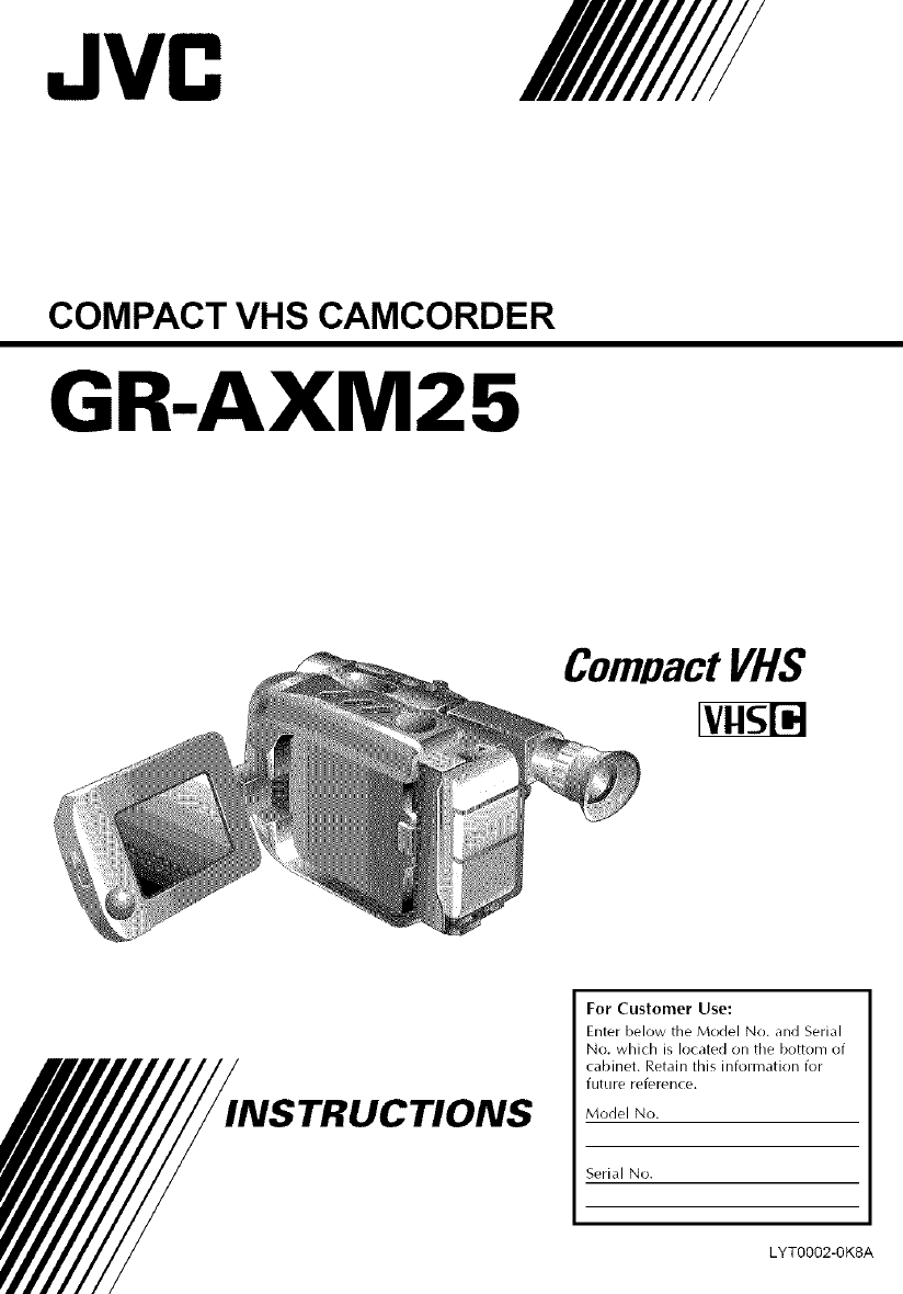
JVC
COMPACT VHS CAMCORDER
GR-AXM25
INSTRUCTIONS
For Customer Use:
Enter below the Model No. and Serial
No. which is located on the bottom of
cabinet. Retain this information for
future reference.
Model No.
Serial No.
LYT0002-0K8A
Dear Customer,
Thank you for purchasing the JVC Compact VHS
camcorder. Before use, please read the safety
information and precautions contained in the
following pages to ensure safe use of your new
camcorder.
Using This Instruction Manual
• All nlajor sections and subsections are listed in the
Table Of Contents (a_" pg. 7).
• Notes appear after nlost subsections. Be sure to read
these as well.
• Basic and advanced features/operation are separated
for easier reference.
It is recommended that you...
...... refer to the hrdex (_" pgs. 45 48) and
familiarize yourself with button locations, etc.
before use.
...... read thoroughly the Safety Precautions and Safety
Instructions that follow. They contain extremely
important information regarding the safe use of
your new camcorder.
You are recommended to carefully read the cautions
on pages 49 and 50 before use.
SAFETY
PRECAUTIONS
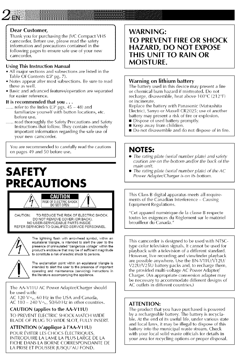
CAUTION: TO REDUCE THE RISK OF ELECTRIC SHOCK
DO NOT REMOVE COVER (OR SACK).
NO USER-SERVICEABLE PARTS INSIDE
REFER SERVICING TO QUALIFIED SERVICE PERSONNEL.
WARNING:
TO PREVENT FIRE OR SHOCK
HAZARD, DO NOT EXPOSE
THIS UNIT TO RAIN OR
MOISTURE.
Warning on lithium battery
The battery Llsed in this device may present a fire
or chemical burn hazard if mistreated. Do not
recharge, disassemble, heat above 100°C (212°F)
or incinerate.
Replace the battery with Panasonic (Matsushita
Electric), Sanyo or Maxell CR2025; use of another
battery may present a risk of fire or explosion.
• Dispose of used battery promptly.
• Keep away from children.
• Do not disassemble and do not dispose of in fire.
NOTES:
•The r,rting plate (serial number plate) and safety
caution are on the bottom and/or the back of the
main unit.
•The rating plate (serial number plate) of the AC
Power Adapter/Charger is on its bottom.
This (:lass B digital apparatus meets all require-
ments of the Canadian Interference Causing
Equipment Regulations.
"Cet appareil num6rique de la classe B respecte
toutes les exigences du R_glement sur le mat6riel
brouilleur du Canada."
The lightning flash with arrowhead symbol within an
equilateral triangle, is intended to alert the user to the
presence of uninsulated "dangerous voltage" within the
produst's enclosure that may be of sufficient magnitude
to constitute a risk of electric shock to persons
The exclamation point within an equilateral triangle is
intended to alert the user to the presence of important
operating and maintenance (servicing) instructions in
the literature accompanying the appliance¸
The AA-V11 U AC Power Adapter/Charger should
be used with:
AC 120 V*, 60 Hz in the USA and Canada,
AC 110 - 240 VQ,, 50/60 Hz in other countries.
CAUTION (applies to the AA-V11 U)
TO PREVENT ELECTRIC SHOCK MAT(E1 WIDE
BLADE OF PLUG TO WIDE SLOT, FULLY INSERT.
ATTENTION (s'applique _ I'AA-V11 U)
POUR EVITER LES CHOCS ELECTRIQUES,
INTRODUIRE LA LAME LA PLUS LARGE DE LA
FICEtE DANS LA BORNE CORRESPONDANTE DE
LA PRISE ET POUSSER JUSQU'AU FOND.
This camcorder is designed to be used with NTSC-
type color television signals. It cannot be used for
playback with a television of a different standard.
Etowever, live recording and viewfinder playback
are possible anywhere. Use the BN-V11U/V12U/
V22U/V25U battery packs and, to recharge them,
the provided multi-voltage AC Power Adapter/
Charger. (An appropriate conversion adapter may
be necessary to accommodate different designs of
AC outlets in different countries.)
ATTENTION:
Tile product that you have purchased is powered
by a rechargeable battery. The battery is recycla-
ble. At the end of its useful life, under various state
and local laws, it may be illegal to dispose of this
battery into the municipal waste stream. Check
with your local solid waste officials for details in
your area for recycling options or proper disposal.
IMPORTANTPRODUCT
SAFETYINSTRUCTIONS
Electrical energy car/perform many useful func-
tions. But irrrproper use car/ resuh in potential
electrical shock or fire hazards. This product has
been engineered and
manufactured to assure your personal safety. In
order not to defeat the built-in safeguards, observe
the following basic rules ik)r its installation, use and
servicing.
ATTENTION:
Follow and obey all warnings and instructions
marl<ed on your product and its operating instruc-
tions. For your safety, [)lease read all the safety and
operating instructions before you operate this
product and keep this manual for future reference.
INSTALLATION
1. Grounding or Polarization
CA)Your product may be equip_aed with a polarized
alternating-current line plug (a plug having one
blade wider than the other). This plug will fit into
the power outlet only one way. This is a safety
feature.
If you are unable to insert the plug fully into the
outlet, try reversing the plug. If the plug should still
fail to fit, contact your electrician to replace your
obsolete outlet. Do not defeat the safety purpose of
the polarized plug.
(g) Your product nlay be equipped with a :;-wire
grounding-type plug, a plug having a third
(grounding) pin. This plug will only fit into a
grounding-type power outlet. This is a safety
feature.
If y% are unable to insert the plug into the outlet,
contact your electrician to replace y%r obsolete
outlet. Do not defeat the safety purpose of the
grounding-type plug.
2. Power Sources
Operate your produd only from tbe type of power
source indicated on tire marking label. If you are not
sure of the type of power supply to your home, consult
your product dealer or local power company. If your
product is intended to operate from battery power, or
other sources, refer to the operating instructions.
3. Overloading
Do not overload wall outlets, extension cords, or
integral convenience receptacles as this can result in a
risk of fire or electric shock.
4. Power Cord Protection
Power supply cords should be routed so that they are
not likely to be walked on or pinched by items placed
upon or against them, paying particular attention to
cords at plugs, convenience receptacles, and the point
where they exit from the product.
5. Ventilation
Slots and openings in tbe cabinet are provided for
ventilation. To ensure reliable operation of the product
and to protect it fronl overheating, these openings must
not be blocked or covered.
• Do not block the openings by placing the product on
a bed, sofa, rug or other similar surface.
• Do not place the product in a built-in installation
such as a bookcase or rack unless proper ventilation
is provided or the manufacturer's instructions have
been adhered to.
6. Wall or Ceiling Mounting
The product should be mounted to a wall or ceiling
only as recommended by the manufacturer.
ANTENNA INSTALLATION
INSTRUCTIONS
1. Outdoor Antenna Grounding
If an outside antenna or cable system is connected to
the product, be sure the antenna or cable system is
grounded so as to provide some protection against
voltage surges and built-up static charges. Article 810
of the National Electrical Code, ANSI/NFPA 70,
provides information with regard to proper grounding
of the mast and supporting structure, grounding of the
lead-in wire to an antenna discharge unit, size of
grounding conductors, location of antenna discharge
unit, connection to grounding electrodes, and
requirements for the grounding electrode.
2. Lightning
For added protection for this product during a lightning
stornl, or when it is left unattended and unused for long
periods of time, unplug it from the wall outlet and
disconnect the antenna or cable system. This will
prevent damage to the product due to lightning and
power line surges.
3. Power Lines
An outside antenna system should not be located in the
vicinity of overhead power lines or other electric light
or power circuits, or where it can fall into such power
lines or circuits. When installing an outside antenna
system, extreme care should be taken to keep from
touching such power lines or circuits as contact with
them might be fatal.
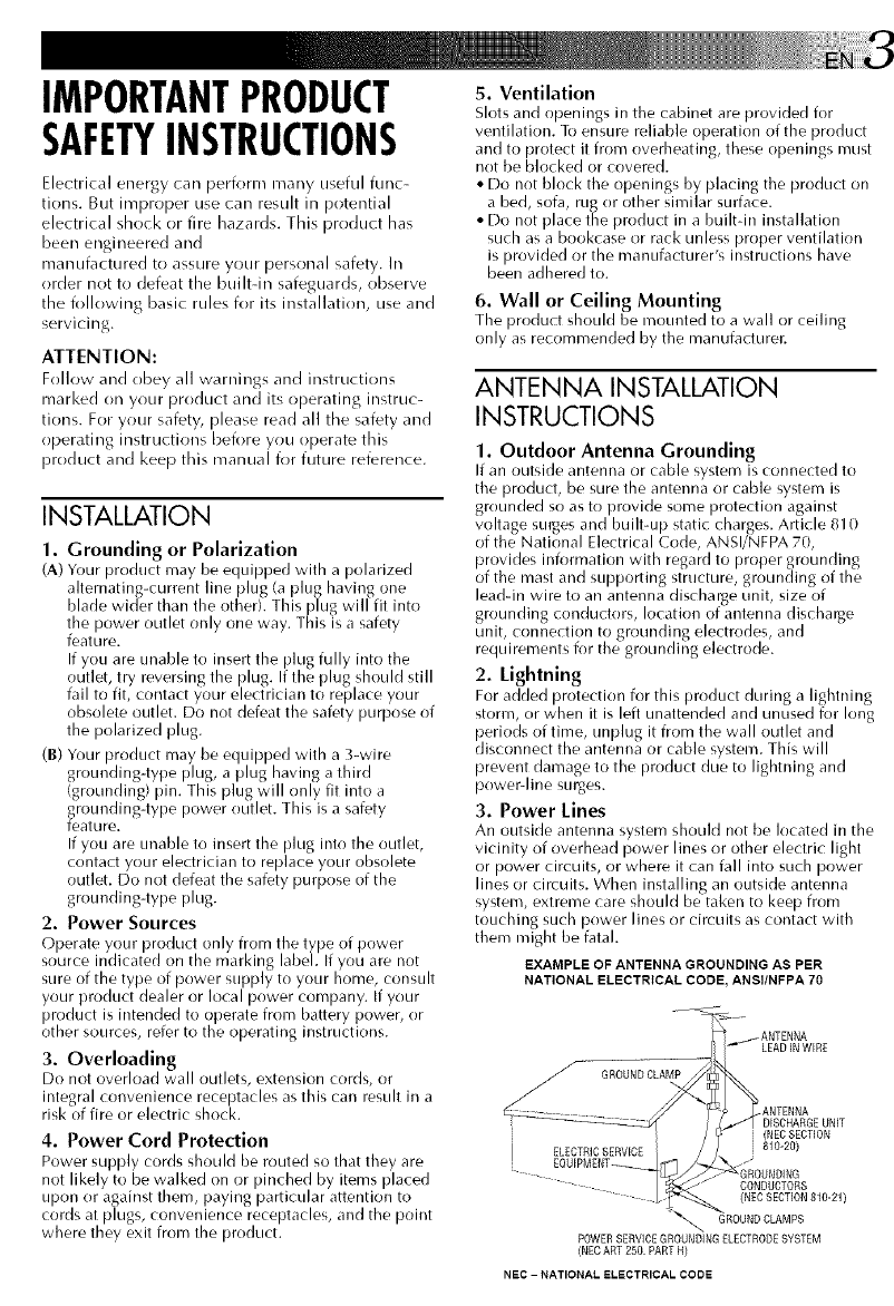
EXAMPLE OF ANTENNA GROUNDING AS PER
NATIONAL ELECTRICAL CODE, ANSflNFPA 70
GROUNDCLAMP
ELECTRICSERVICE
LEADINWIRE
.ANTENNA
DISCHARGEUNIT
(NECSECTION
810-20)
CONDUCTORS
(NEC SECTION 810-21)
GROUND CLAMPS
(NEC ART 250. PART H)
NEC - NATIONAL ELECTRICAL CODE
USE
1. Accessories
To avoid personal injury:
• Do not place this product on an unstable cart,
stand, tripod, bracket or table. It may fall, causing
serious injury to a child or adult, and serious
damage to the product.
• Use only with a cart, stand, tripod, bracket, or
table recommended by the manufacturer or sold
with the product.
• Use a mounting accessory recommended by the
manufacturer and i_fllow the manufacturer's
instructions for any mounting of the product.
• Do not try to roll a cart with small casters across
thresholds or deep-pile carpets.
2. Product and Cart Combination
A product and cart combination should be moved
with care. Quick stops, excessive ik)rce, and uneven
surfaces may cause the product and cart combina-
tion to overturn.
3. Water and Moisture PORTABLSCARTWARNING
Do not use th is product (Symbol_provided by RSTAC)
near water for example,
near a bath tub, wash
bowl, kitchen sink or
laundry tub, in a wet
baselnent, or near a
swimming pool and the
like.
4. Object and Liquid Entry
Never push objects of any kind into this product
through openings asthey may touch dangerous
voltage points or shorbout parts that could result in
a fire or electric shock. Never spill liquid of any
kind on the product.
5. Attachments
Do not use attachments not recommended by the
manufacturer of this product as they may cause
hazards.
6. Cleaning
Unplug this product from the wall outlet bei_)re
cleaning. Do not use liquid cleaners or aerosol
cleaners. Use a damp cloth i_)r cleaning.
7. Heat
The product should be situated away from heat
sources such as radiators, heat registers, stoves, or
other products (including amplifiers) that produce
heat.
SERVICING
1. Servicing
If your product is not operating correctly or exhibits
a marl<ed change in performance and you are
unable to restore normal operation by ik)llowing the
detailed procedure in its operating instructions, do
not attempt to service it yourself as opening or
removing covers may expose you to dangerous
w)ltage or other hazards. Refer all servicing to
qualified service personnel.
2. Damage Requiring Service
Unplug this product from the wall outlet and refer
servicing to qualified service personnel under the
ik)llowing conditions:
a. When the power supply cord or plug is damaged.
b. If liquid has been spilled, or objects have fallen
into the product.
c. If the product has been exposed to rain or water.
d. If the product does not operate normally by
following the operating instructions. Adjust only
those controls that are covered by the operating
instructions as an improper adjustment of other
controls may result in damage and will often
require extensive work by a qualified technician
to restore the product to its normal operation.
e. If the product has been dropped or damaged in
any way.
f. When the product exhibits a distinct change in
performance_his indicates a need for service.
3. Replacement Parts
When replacement parts are required, be sure the
service technician has used replacement parts
specified by the manufacturer or have the same
characteristics as the original part. Unauthorized
substitutions may result in fire, electric shock or
other hazards.
4. Safety Check
Upon completion of any service or repairs to this
product, ask the service technician to perform safety
checl<sto determine that the product is in safe
operating condition.
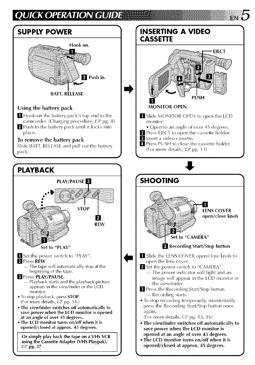
SUPPLY POWER
Hook oil.
[] Push in.
BATT. RELEASE
Using the battery pack
[] Hot)k-on tile battery pack's top end to the
camcorder. (Charging procedure, _T_ pg. 8)
mPush in the battery pad< until it locks into
[)lace.
To remove the battery pack
Slide BATT. RELEASE and pull out the battery
pack.
PLAYBACK
PLAY/PAUSE
..IP
STOP
REW
[] Set the power switch to "PLAY".
[] Press REW.
The tape will automatically stop at the
beginning of the tape.
[] Press PLAY/PAUSE.
Playback starts and the playback picture
appears in the viewfinder or the LCD
monitor.
•To stop playback, press STOP.
(For more details, _-_#"pg. 34.)
•The viewfinder switches off automatically to
save power when the LCD monitor is opened
at an angle of over 45 degrees.
•The LCD monitor turns on/off when it is
opened/closed at approx. 45 degrees.
Or simply play back the tape on a VHS VCR
using the Cassette Adapter (VHS Playpak).
[L2__ pg. 37
INSERTING A VIDEO
CASSETI'E
ECT
[]
MONITOR OPEN
PUSH
[] Slide MONITOR (-)PEN to open the LCD
nlonitor.
• Open to an angle of over 45 degrees.
[] Press ELECT to ()pen the cassette holder.
[] Insert a video cassette.
[] Press PUSH to close the cassette holder.
(For more details, _T_ pg. 13}
.!
SHOOTING
SCOVER
en/dose knob
Recording Start/Stop button
[] Slide the LENS COVER open/dose I<nob to
()pen the lens cover.
[] Set the power switch to "CAMERA".
The power indicator will light and an
image will appear in the LCD monitor or
the viewfinder.
[] Press the Recording Start/Stop button.
Recording starts.
• To stop recording temporarily, momentarily
press the Recording Start/Stop button once
again.
(For more details, _:-z_ pg. 15, 16)
•The viewfinder switches off automatically to
save power when the LCD monitor is
opened at an angle of over 45 degrees.
• The LCD monitor turns on/off when it is
opened/dosed at approx. 45 degrees.
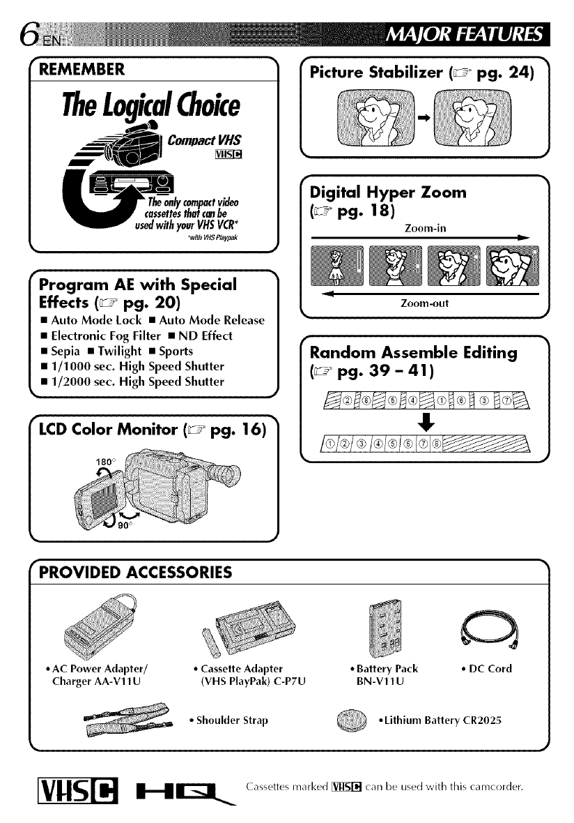
•REMEMBER
TheL izcalChoice
__] Compact VHS
usedwithyourVHSVCR*
_v_ _$ P/ayf_k
Program AE with Special
Effects (_ pg. 20)
• Auto Mode Lock •Auto Mode Release
•Electronic Fog Filter •ND Effect
•Sepia •Twilight •Sports
•1/1000 sec. High Speed Shutter
•1/2000 sec. High Speed Shutter
•
LCD Color Monitor (_ pg. 16)
180 °
rPicture Stabilizer (_° pg. 24)
rDigital Hyper Zoom
(_° pg. 18)
Zoom-in u_
9
Zoom-out
rRandom Assemble Editing
(_ pg. 39 - 41)
I, 1
%
PROVIDED ACCESSORIES
• AC Power Adapter/ •Cassette Adapter •Battery Pack
Charger AA-V11U (VHS PlayPak) C-P7U BN-V11U
•DC Cord
•Shoulder Strap Lithium Battery CR202_
HIZ] ( assettes marked [_ can be used with this camcorder.
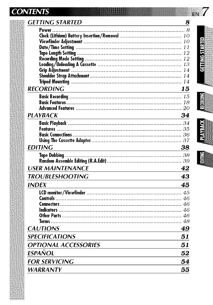
GETTING STARTED 8
Power..................................................................................... 8
Clock(Lithium)BatteryInsertion/Removal........................................ ]0
ViewfinderAdjustment............................................................... ]0
Date/TimeSetting.................................................................... ] ]
TopeLengthSetting................................................................... ]2
RecordingModeSetting.............................................................. ]2
Loading/UnloadingA Cassette...................................................... ]3
GripAdjustment....................................................................... ]4
ShoulderStrapAttachment........................................................... ]4
TripodMounting....................................................................... ]4
RECORDING 15
BasicRecording........................................................................ ]5
BasicFeatures.......................................................................... ]8
AdvancedFeatures.................................................................... 20
PLAYBACK 34
BasicPlayback......................................................................... 34
Features................................................................................ 35
BasicConnections...................................................................... 36
UsingTheCassetteAdapter.......................................................... 37
EDITING 38
TapeDubbing........................................................................... 38
RandomAssembleEditing(R.A.Edit)................................................ 39
USER MAINTENANCE 42
TROUBLESHOOTING 43
INDEX 45
LCDmonitor/Viewfinder ............................................................. 45
Controls................................................................................. 46
Connectors.............................................................................. 46
Indicators............................................................................... 46
OtherParts............................................................................. 46
Terms.................................................................................... 48
CA UTIONS 49
SPECIFICATIONS 51
OPTIONAL ACCESSORIES 51
ESPAI_IOL 52
FOR SERVICING 54
WARRANTY 55
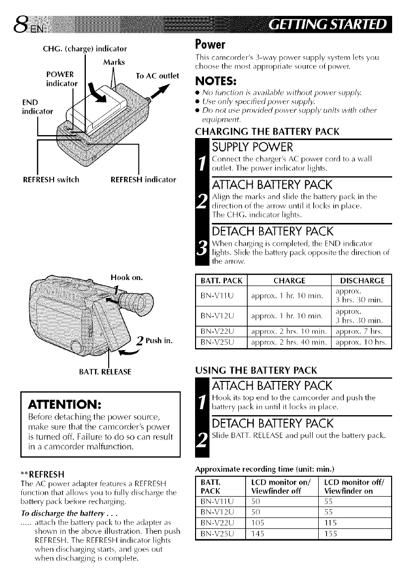
CHG. (charge) indicator
Marks
POWER
indicator
END
indicator
REFRESH switch
To AC outlet
REFRESH indicator
Hook on.
2Push in.
Power
This carrrcorder's 3-way power supply system lets you
choose the most appropriate source of powen
NOTES:
•N_ function is aw_ilable with_ut power supply.
• Use only _pecified povwr supply.
• Do not use provided power supply units with other
equipment.
CHARGING THE BATTERY PACK
SUPPLY POWER
Connect the charger's AC power cord to a wall
outlet. The power indicator lights.
ATTACH BATTERY PACK
Align the marl<sand slide the battery pack in the
direction of the arrow until it Iocl<s in place.
The CHG. indicator lights.
DETACH BATTERY PACK
When charging is completed, the END indicator
lights. Slide the battery pack opposite the direction of
the arrow.
BATT. PACK CHARGE DISCHARGE
approx.
BN-V11U approx. 1 hr. 10 rain. _ hrs. _0 rain.
BN-V12U approx. 1 hr. 10 min. approx.
hrs. _0 rain.
BN-V22U approx. 2hrs. 10min. approx. 7hrs.
BN-V25U approx. 2hrs. 40min. approx, lOhrs.
USING THE BATTERY PACK
_ TTACH BATTERY PACK
Hook its top end to the camcorder and push the
battery pack in until it Iocl<s in place.
DETACH BATTERY PACK
Slide BATT. RELEASE and pull out the battery pacl<.
Approximate recording time (unit: rain.)
BATT. LCD monitor on/ LCD monitor off/
PACK Viewfinder off Viewfinder on
BN-V11U 50 55
BN-V12U 50 55
BN-V22U 105 115
BN-V25U 145 155
BAT_ RELEASE
ATTENTION:
Before deta( hing the power source,
make sure that the camcorder's power
is turned off. Failure to do so can result
in a camcorder malfunction.
**REFRESH
The AC power adapter features a REFRESH
function that allows you to fully discharge the
battery pack before recharging.
To discharge the battery...
..... attach the battery pack to the adapter as
shown in the above illustration. Then push
REFRESH.The REFRESHindicator lights
when discharging starts, and goes out
when discharging is complete.
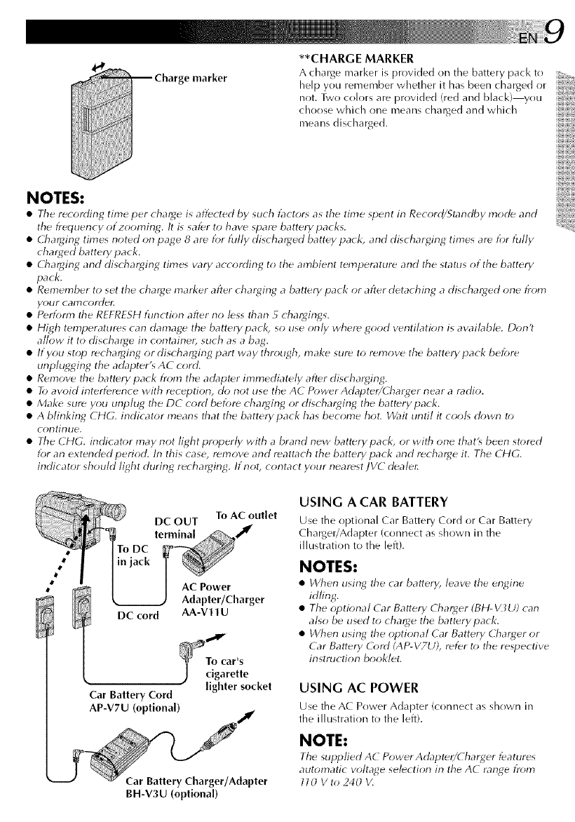
e marker
**CHARGE MARKER
A charge marl<er is provided on the battery pacl<to
help you remember whether it has been charged or
not. Two colors are provided (red and black) you
choose which one means charged and which
means discharged.
NOTES:
•Tile recording time per charge is affected by such t_lctr)r_ as tile time spent in Record/Standby mocb and
tile frequency of zooming. It is safer to have spare battery packs.
•Cha_ging times noted on page 8 are for fully discharged battey pack, and discharging times are for fully
cha_ed battery pack.
• Cha_ging and discharging time_ vary according to the ambient temperature and tile status of the battery
pack.
• Remember to set the charge marker after charging a battery pack or after detaching a discharged one i)om
your camcordel:
• Perform tile REFRFSH function after no less than 5chargings.
• High temperatures can damage the battery pack, so use only where good ventilation is available. Don't
allow it to discharge in containe_, such as a bag.
• If you stop recharging or discharging part way through, make sure to remove the battery pack before
unplugging the adapter's AC cord.
• Remove tile battery pack from the adapter immediately after discharging.
• To avoid interference with reception, do not use the AC PowerAdapte_/Charger near a radio.
• Make sure you unplug tile DC cord before charging or discharging the battery pack.
• A blinking CHG. indicator means that the batterypack has become hot. Wait until it cool_ down t_)
continue.
• Tile CHG. indicator may not light properly with a brand new battery pack, or with one that_ been stored
for an extended period. In this case, remove and reattach the battery pack and recharge it. Tile CHG.
indicator should light during recharging. If not, contact your nearest JVC deale_
To AC outlet
DC OUT
terminal
AC Power
Adapter/Charger
DC cord AA-V11 U
_To car's
.)cigarette
lighter socket
Car Battery Cord
AP-V7U (optional)
Car Battery Charger/Adapter
BH-V3U (optional)
USING A CAR BATTERY
Use tile optional Car Battery Cord or Car Battery
Charger/Adapter (connect as shown in the
illustration to the left).
NOTES:
• When using tile car battery, leave tile engine
idling.
• Tile optional Car Ba_.ery Charger (BH-_Z_U) can
also be used to cha_ge the battery pack.
• When using tile optional Car Battery Charger or
Car Battery O)rd (AP- V7U), refer to tile respective
instruction booklet,
USING AC POWER
Use tile AC Power Adapter (connect as shown in
the illustration to the left).
NOTE:
Tile supplied AC Power Adapte_/(harger features
automatic vohage selection in the AC lange fr_)m
l l O V to 240 V,
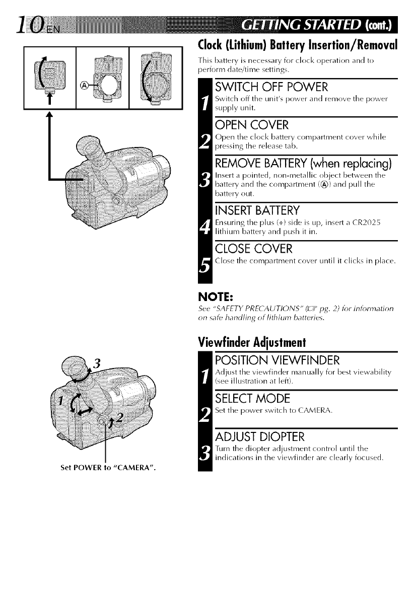
Set POWER to "CAMERA".
Clock(Lithium)BatteryInsertion/Removal
This battery is necessary for clock operation and to
perform date/time settings.
SWITCH OFF POWER
Switch off tile unit's power and remove tile power
supply unit.
OPEN COVER
Open the clock battery compartment cover while
pressing the release tab.
REMOVE BAI-rERY (when replacing)
Insert a pointed, non-metallic object between the
battery and the compartment ((_)) and pull the
battery out.
INSERT BATTERY
Ensuring the plus (+) side is up, insert a CR2025
lithium battery and push it in.
CLOSE COVER
Close the compartment cover until it clicks in place.
NOTE:
See "SAFETY PRECAUTIONS" (__pg. 2) for information
on saf_ handling of lithium batteries.
ViewfinderAdjustment
POSITION VIEWFINDER
Adjust the viewfinder manually for best viewability
(see illustration at left).
SELECT MODE
Set the power switch to CAMERA.
ADJUST DIOPTER
Turn the diopter adjustment control until the
indications in the viewfinder are clearly focused.
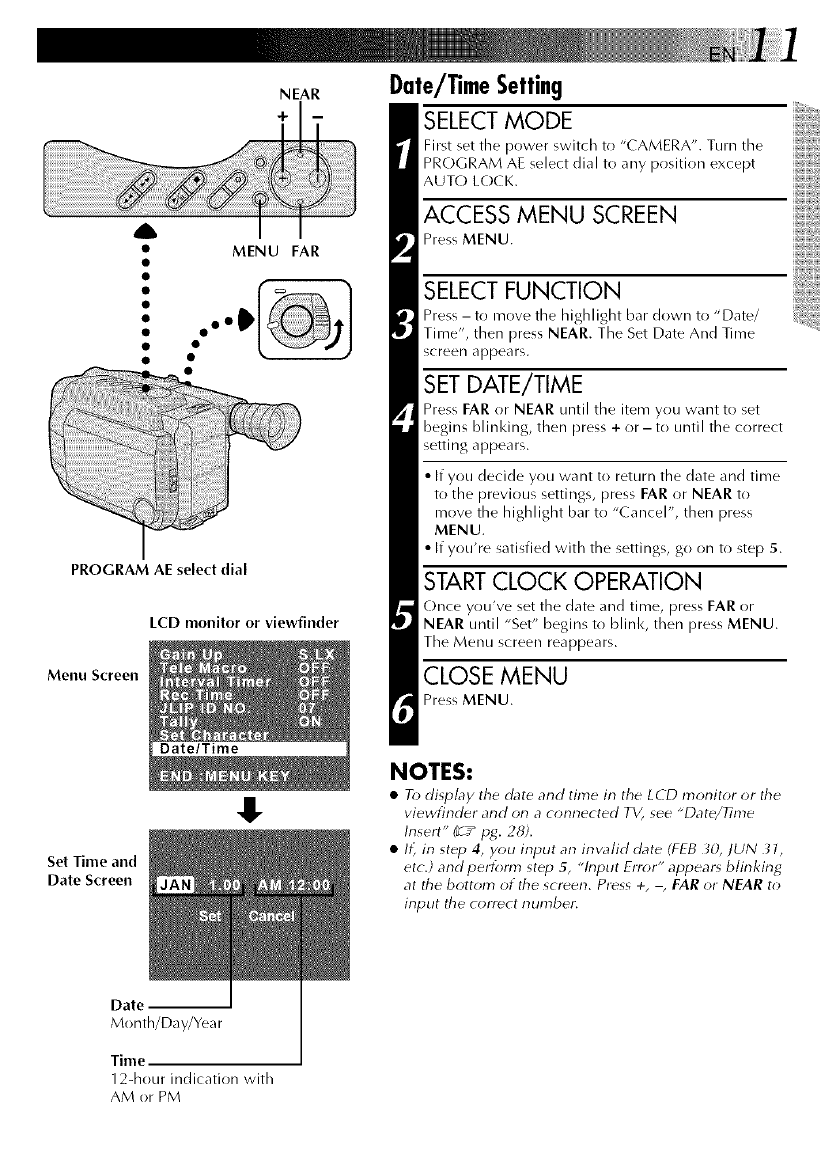
NEAR
+
A
• MENU FAR
PROGRAM AE select dial
LCD monitor or viewfinder
Menu Screen
Date/Time
Set Time and
Date Screen
!.
Date/TimeSetting
SELECT MODE
First set the power switch to "CAMERA". Turn the
PROGRAM AE select dial to any position except
AUTO LOCK.
ACCESS MENU SCREEN
Press MENU.
SELECT FUNCTION
Press -to move the highlight bar down to "Date/
Time", then press NEAR. The Set Date And Time
screen appears.
SET DATE/TIME
Press FAR or NEAR until the item you want to set
begins blinl<ing, then press + or - to until the correct
setting appears.
•If you decide you want to return the date and time
to the previous settings, press FAR or NEAR to
move the highlight bar to "Cancel", then press
MENU.
• If you're satisfied with the settings, go on to step 5.
START CLOCK OPERATION
(-)nce you've set the date and time, press FAR or
NEAR until "Set" begins to blink, then press MENU.
The Menu screen reappears.
CLOSE MENU
Press MENU.
NOTES:
•To display the date and time in the LCD monitor or the
viewfinder and on a connected TV, see "Date/Time
Insert" (__pg. 28).
•Ii_ in step 4, you input an inw_lid date (FEB _;0, JUN 31,
etc.] and perform st_p 5, "h_put Error" appear_ blinking
at the bottom of the screen. Press +, -, FAR or NEAR to
input the correct number.
Date
Month/Day/Yea r
Time
12-hour indication with
AM or PM
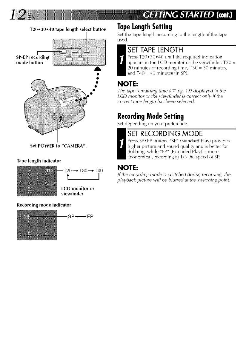
T20 • 30o 40 tape length select button
mode button
A
TapeLengthSetting
Set the tape length according to tile length of the tape
used.
I SET TAPE LENGTH
Press T20° _0°40 until the required indication
appears in the LCD monitor or the veiwfinder. T20 =
20 minutes of recording time, T_0 =_0 minutes,
and T40 = 40 minutes (in SP).
NOTE:
Tile tape r_maining time (_ ply. l _) displayed in tile
LdD monitor or the viewfinder is tonoct only if the
correct tape length has been selected.
Set POWER to "CAMERA".
Tape length indicator
--T20"--_ T30"--_ T40
t I
LCD monitor or
viewfinder
RecordingModeSetting
Set depending on your preference.
I ET RECORDING MODE
Press SP° EP button. "SP" (Standard Play) provides
higher picture and sound quality and is better for
dubbing, while "EP" (Extended Play) is more
economical, recording at 1/_ the speed of SR
NOTE:
If the recording mode is switched during recording, tile
playback picture will be blurred at the switching point.
Recording mode indicator
SP_,_- EP
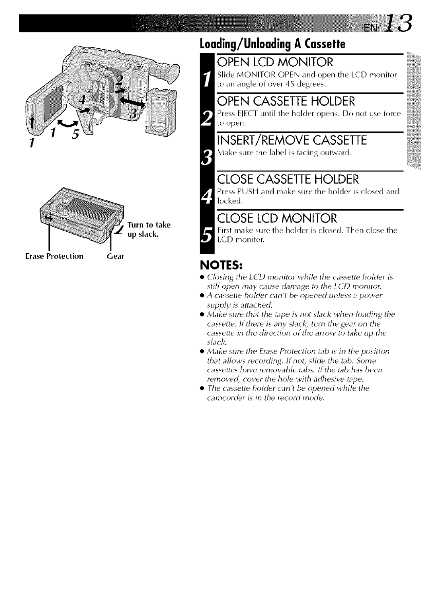
Erase Protection
Turn to take
up slack.
Gear
L0ading/Unl0adingACassette
OPEN LCD MONITOR
Slide MONITOR OPEN and open the LCD rrronitor
to an angle of over 45 degrees.
OPEN CASSETTE HOLDER
Press ELECT until the holder opens. Do not use force
to ()pen.
INSERT/REMOVE CASSETTE
Make sure the label is facing outward.
CLOSE CASSETTE HOLDER
Press PUSH and make sure the holder is closed and
locked,
CLOSE LCD MONITOR
First make sure the holder is closed. Then close the
LCD moniton
NOTES:
•Closing tile LCD monitor whil_ tile cassette holder is
still open may cause damage to tile LCD monitor:
• A cassette holder can't be opened unless a power
supply is attached.
• Make sur_ that the tape is not sbck when loading the
cassette. If there is any slack, turn tile gear on the
cassette in the direction of the arrow to take tip the
slack.
• Make sure the Frase Protection tab is in the position
that allows recording. If not, slide the tab. Some
cassettes have r_movable tabs. If the tab has been
removed, cover tile hole with adhesive tape.
• Tile cassett_ holder can't be opened while the
camcord_r is in the record mode.
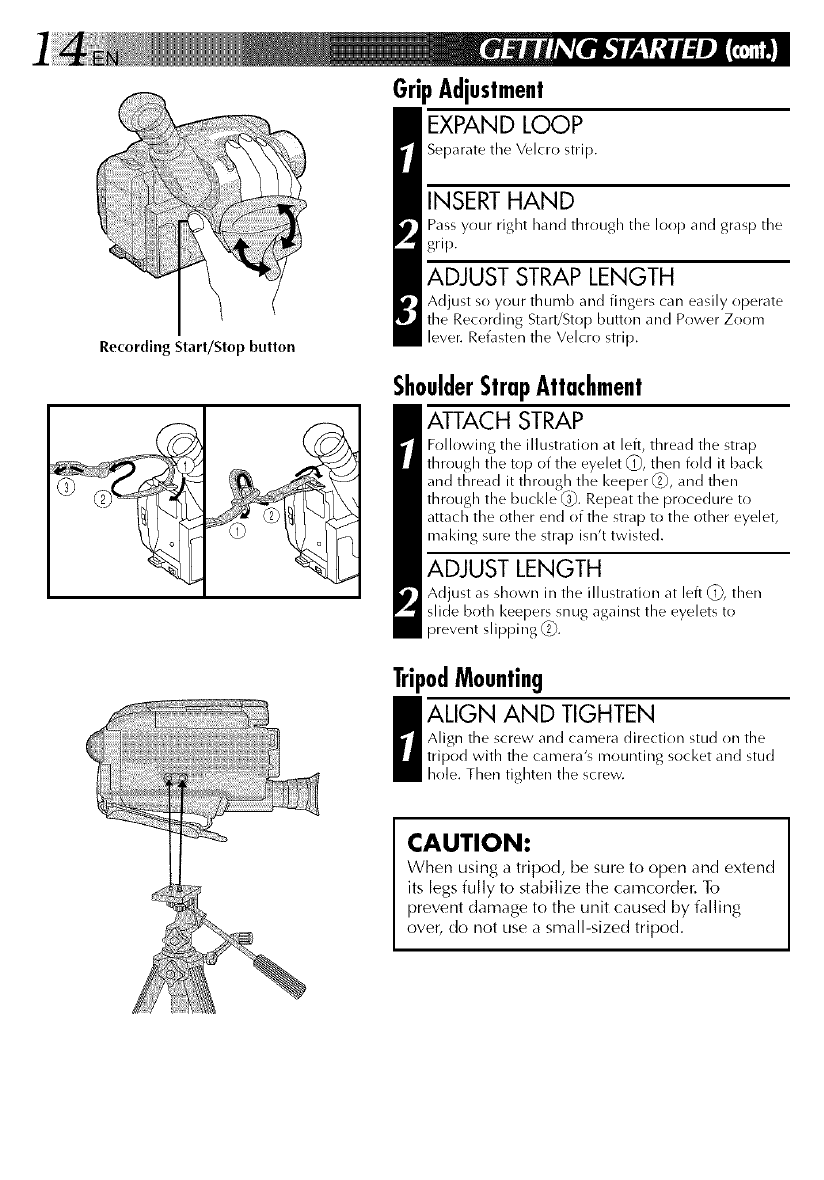
Recording Start/Stop button
GripAdjustment
EXPAND LOOP
Separate the Velcro strip.
INSERT HAND
Pass your right hand through the loop and grasp the
grip.
ADJUST STRAP LENGTH
Adjust so your thumb and fingers can easily operate
the Recording Start/Stop button arrd Power Zoom
lever. Refasten the Velcro strip.
ShoulderStrapAttachment
ATTACH STRAP
Following the illustration at left, thread the strap
through the top of the eyelet (_, then fold it back
and thread it through tile keeper _, and then
through tile buckle _,1_.Repeat tile procedure to
attach the other end of the strap to the other eyelet,
maldng sure the strap isn't twisted.
ADJUST LENGTH
Adjust as shown in the illustration at left (_), then
slide both keepers snug against the eyelets to
prevent slipping _2_.
TripodMounting
I LIGN AND TIGHTEN
Align the screw and camera direction stud on the
tripod with the camera's mounting socket and stud
hole. Then tighten the screw.
CAUTION:
When using a tripod, be sure to open and extend
its legs fully to stabilize the camcorder. To
prevent damage to the unit caused by falling
over, do not use a small-sized tripod.
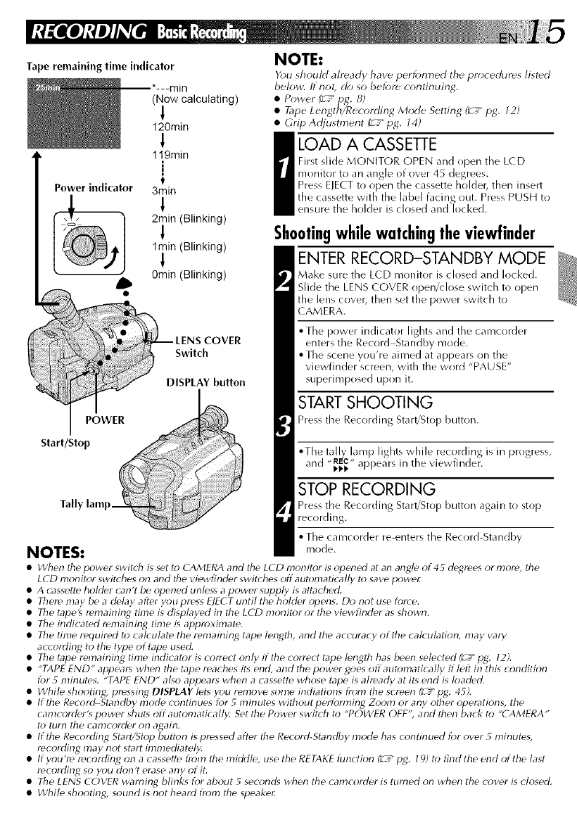
Tape remaining time indicator
POWER
(Now calculating)
1
120rain
!
119rain
[
3min
1
2rain (Blinking)
1
1rain (Blinking)
!
0rain (Blinking)
COVER
Switch
DISPLAY button
Start/Stop
NOTE:
You should already have performed tile procedures listed
below. If not, do so before continuing.
•Power (¢ _pg. 8)
• Tape Length/Recording Mode Setting (_r_" pg. 12)
• GripAdjustment (r__pg. 14)
a OAD A CASSETTE
First slide MONITOR OPEN and open tlne LCD
monitor to an angle of over 45 degrees.
Press ELECT to open the cassette holdel_ then insert
the cassette with the label facing out. Press PUSH to
ensure the holder is closed and locked.
Shootingwhilewatchingtheviewfinder
ENTER RECORD-STANDBY MODE
Make sure the LCD mr)nitor is closed and locked.
Slide the LENS COVER open/close switch to open
the lens cover, then set the power switch to
( AMERA.
• The power indicator lights and the camcorder
enters the Record Standby mode.
• The scene you're aimed at appears on the
viewfinder screen, with the word "PAUSE"
superimposed upon it.
START SHOOTING
Press the Recording Start/Stop button.
• The tally lamp lights while recording is in progress,
and "_._" appears in the viewfinder.
STOP RECORDING
Press the Recording Start/Stop button again to stop
recording.
• The camcorder re-enters the Record-Standby
NOTES: mode.
•When the power swit(h is set to CAMERA and the LCD monitor is opened at an angle of 4_ degrees or more, the
LCD monitor swit( hes on and the viewfinder swit( hes off automatically to save power
• A c_ssette holder c_n't be opened unless a power supply is attached.
• There may be a delay after you pre_s E)ECT until the holder opens. Do not use force.
• The tape's remairgng time is displayed in the LCD morgtor or the viewfinder as shown.
• The indicated remairgng time is approximate.
• The time required to calculate the remairgng tape length, and the accuracy of the calculation, may vary
according to the type of tape used.
• The tape remaining time indicator is correct only if the correct tape length has been selected (__" pg. 12).
•"TAPE END" appears when the tape reaches its end, and the power Goes off automatically if left in this condition
for 5 minutes. "TAPE END" also appears when a cassette whose tape is already at its end is loaded.
_White shooting, pressing DISPLAY lets you remove some indiations from the screen f_-_"pg. 4_).
If the Record Standby mode continues for _minutes without performing Zoom or any other operations, the
camcorder's power shut_ off automatically. Set the Power swit( h to "POWER OFF', and then back to "(AMERA"
to turn the camcorder on again.
• If the Recording Start/Stop button is pressed after the Record-Standby mode has continued for over _minutes,
recording may not start immediately.
• If you're recording on a cassette from the middle, use the RETAKE flmction (L_" pg. 19) to find the end of the last
recording so you don't erase any of if.
• The LENS COVER warning blinks for about _ seconds when the camcorder is turned on when the cover is closed.
•While shooting, sound is not heard from the speake_
POWER I
Start/Stop _1
Power indica
MONITOR
OPEN
Tape remaining time indicator
(Now calculating)
!
120rain
119min
1
1
t
3min
!
2rain (Blinking)
1rain (Blinking)
ShootingwhilewatchingtheLCDmonitor
Before the following steps, perform step 1 (_T_ pg. 15}.
ENTER RECORD-STANDBY MODE
Make sure the LCD rrrr)nitor is fully open. Slide the
LENS COVER open#lose switch to open the lens
cover, then set the power switch to CAMERA.
• The power indicator lights and the ca mcorder
enters the Record Standby mode.
• The scene you're aimed at appears in the LCD
monitor, with the word "PAUSE" superimposed
upon it.
START SHOOTING
Tilt the LCD monitor upward/downward for best
viewability (_-T_ pg. 17) and press the Recording
Start/Stop button.
• The tally lamp lights while recording is in progress,
,,REC,,
and _1_ appears in tile L(D monitor.
STOP RECORDING
Press the Recording Start/Stop button again to stop
recording.
• The camcorder re-enters the Record-Standby
mode.
NOTES:
•When you use the LCD monitor outdoors in di_ct
sunlight, the LCD monitor may be difficult to see. If this
happens, we recommend that you use tile viewfinder
(_r_H£. l _).
• For other note_, Iefer to Hg. 15.
Tally lamp
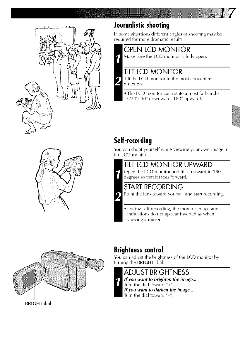
Journalisticshooting
Ill some situations different angles of slror)ting may be
required for more dramatic results.
OPEN LCD MONITOR
Make sure the L(D monitor is fully open.
TILTLCD MONITOR
Tilt the LC D monitor in the irrost convenient
direction.
*The LCD monitor can rotate almost full circle
(270°: 90 ° downward, 180 ° upward).
Self-recording
You can shoot yourself while viewing your own image in
the L(D monitor.
TILTLCD MONITOR UPWARD
Open the LCD monitor and tilt it upward to 180
degrees so that it faces forward.
START RECORDING
Point the lens toward yourself and start recording.
• During self-recording, the monitor image and
indications do not appear inverted as when
viewing a mirror.
BRIGHT dial
Brightnesscontrol
You can adjust the brightness of the L(D monitor by
turning the BRIGHT dial.
I DJUST BRIGHTNESS
If you want to brighten the image...
Turn the dial toward "+".
If you want In darken the image...
Turn the dial toward "-".
Zoom-in
Zoonl-out
bar
indicator
Power zoom lever
FEATURE:
PURPOSE:
OPERATION:
NOTES:
Zooming
To produce the zoom in/out effect, or
an instantaneous change in image
magnification.
36X Hyper zoom
Digital circuitry doubles the
maximum 18x magnification offered
by optical zoom.
1) To zoom in, slide the Zoom Lever
toward "T".
2) To zoom out, slide toward "W".
•During Hyper Z_)om, the speed
increases the further y_u slide the
Z_)om Lever.
• Focusing may become unstable
during Hyper Z_;om. In this case,
set the zoom while in Rec_;rd
Standby, set manual focus or Focus
Lock (¢_pg. 22, 2 _), then zoom in
or out in Record mode.
• The Zoom Level Indicator (11) only
moves during optical zoom. Once
the Zoom Level indicator reaches
the top of the zoom indicator bar,
all magnification fr_;m that point is
through digital pr_cessing.
• During digital image processing,
the quality of the image may suffer.
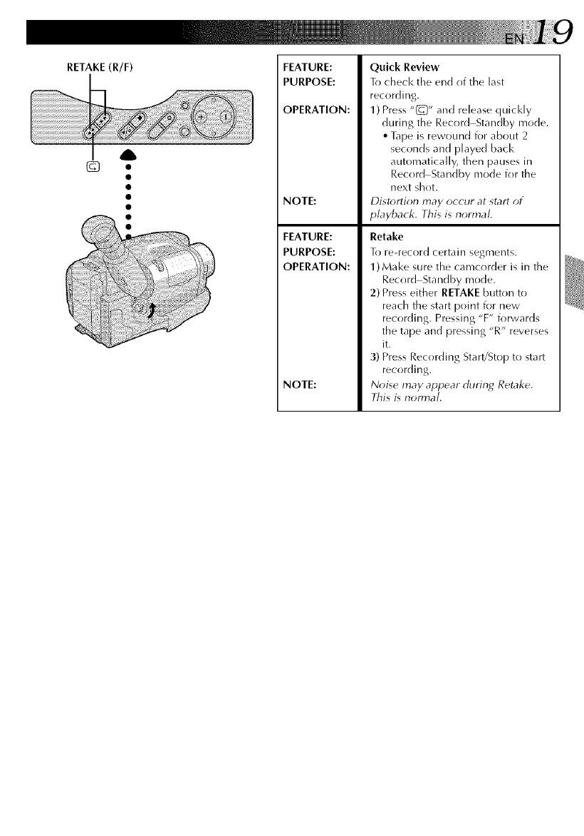
RETAKE(R/F) FEATURE:
PURPOSE:
OPERATION:
NOTE:
FEATURE:
PURPOSE:
OPERATION:
NOTE:
Quick Review
To check the end of the last
recording.
1) Press "(_)" arrd release quicl<ly
during the Record Standby mode.
•Tape is rewound for about 2
seconds and played back
automatically, then pauses in
Record Standby mode for the
next shot.
Distr;rtion may occur at start of
playback. This is normal.
Retake
To re-record certain segnrentg,
1)Make sure the camcorder is in the
Record Standby mode.
2) Press either RETAKE button to
reach the start point for new
recording. Pressing "F" forwards
the tape and pressing "R" reverses
it.
3) Press Recording Start/Stop to start
recording.
Noise may appear during Retake,
This is nom_aL
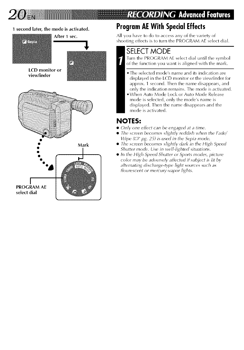
1 second later, the mode is activated.
After 1 sec.
LCD monitor or
viewfinder
I
PROGRAM AE
select dial
ProgramAEWithSpecialEffects
All you have to do to access any of the wlriety of
shooting effects is to turn the PROGRAM AE select dial.
SELECT MODE
Turn the PROGRAM AE select dial until tile symbol
of the function you want is aligned with the marl<.
,,The selected mode's name and its indication are
displayed in the LCD monitor or the viewfinder for
approx. 1 second. Then the name disappears, and
only the indication remains. The mode is activated.
• When Auto Mode Loci< or Auto Mode Release
mode is selected, only the mode's name is
displayed. Then the name disappears and the
mode is activated.
NOTES:
•Only one effect can be engaged at atime.
• Tile sct_en becomes slightly r_ddish when the Fad_/
Wipe (_r_" pg. 2_) is used in the Sepia mode.
• Tile screen becomes slightly dark in tile High Speed
Shutter mode. Use in w_ll-light_d situations.
• In the High Speed Shutter or Sports modes, picture
color may be adversely affected if subject is lit by
alternating discharge4ype light sources such as
flourescent or mercury-vapor lights.
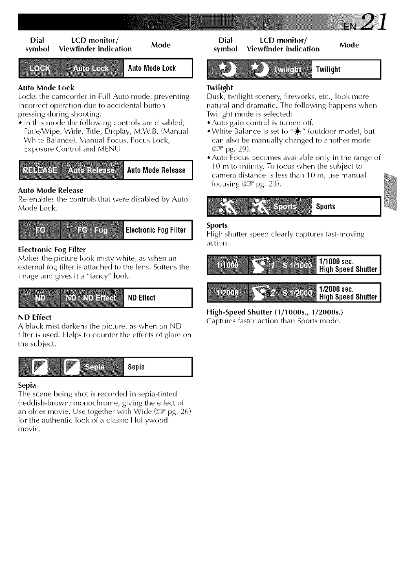
Dial LCD monitor/ Mode
symbol Viewfinder indication
AutoModeLock ]
/
Auto Mode Lock
Locks the camcorder in Full Auto mode, preventing
incorrect operation due to accidental button
pressing during shooting.
•In this mode the i_)llowing controls are disabled;
Fade/Wipe, Wide, Title, Display, M.W.B. (Manual
White Balance), Manual Focus, Focus Lock,
Exposure Control and MENU
I
AutoMode Release ]
Auto Mode Release
Re-enables the controls that were disabled by Auto
Mode Loci<.
ElectronicFogFilter 1
Electronic Fog Filter
Makes the picture Ioo1<misty white, as when an
external i_g filter is attached to the lens. Softens the
image and gives it a "fancy" look.
NDEffect ]
ND Effect
A black mist darkens the picture, as when an ND
filter is used. Helps to counter the effects of glare on
the subject.
Sepia ]
Sepia
Dial LCD monitor/ Mode
symbol Viewfinder indication
Twilight ]
Twilight
Dusk, twilight scenery, fireworks, etc., look more
natural and dramatic. The following happens when
Twilight mode is selected:
• Auto gain control is turned off.
• White Balance is set to "-_-" (outdoor mode), but
can also be manually changed to another mode
_T_ pg. 29).
•Auto Focus becomes available only in the range of
10 mt() infinity. To focus when the subject-to-
camera distance is less than 10 m, use manual
focusing (_T_ pg. 2_).
Sports ]
Sports
High shutter speed clearly captures fast-moving
action.
1/1000sec, ]
HighSpeedShutter
1/2000sec. ]
HighSpeedShutter
High-SpeedShutter (1/1000s., 1/2000s.)
Captures fasteraction than Sports mode.
The scene being shot is recorded in sepia-tinted
(reddish-brown) mon()chrome, giving the effect ()f
an older movie. Use together with Wide (_-T_ pg. 26)
for the authentic Ioo1<of a classic Hollywood
Ir/ovie.
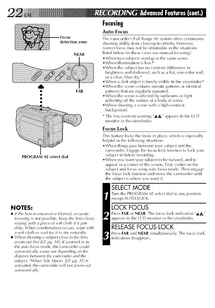
detection zone
NEAR
A
• FAR
PROGRAM AE select dial
NOTES:
•If the lens is smeared or blurred, accurate
focusing is not possibl_. K_p the lens clean,
wiping with a piece of soft cloth if it get,
dirty. When condensation occur,, wipe with
asoft cloth or wait for it to dry naturally.
• I/Vhen shooting asubject close t(> ttle len_,
zoom-out illst (__" pg. 18). If zoomed-in in
the auto focus mode, the camcorder could
automatically zoom out depending on the
distance between the camcorder and the
subject, q/Vhen Tele Macro (_" pg. 31) is
activated, the carncorder will not zoom ()tit
automatically.
Focusing
Auto Focus
The camcorder's Full Range AF system offers continuous
shooting ability from close-up to infinity. However,
correct fl)cus may not be obtainable in the situations
listed below (in these cases use manual fl)cusing}:
,,When two subjects overlap in the same scene.
oWhen illumination is low.*
• When the subject has no contrast (difference in
brightness and darl<ness), such as a flat, one-color wall,
or a clear, blue sky.*
,,When a dark object is barely visible in the viewfinder.*
• When the scene contains minute patterns or identical
patterns that are regularly repeated.
• When the scene is affected by sunbeams or light
reflecting off the surface of a body of water.
• When shooting a scene with a high-cr)ntrast
bacl<ground.
* The low-contrast warning ,,@,._e,, appears in the L(D
monitor or the viewfinder.
Focus Lock
This feature locks the focus in place, which is especially
helpful in the following situations:
• When things pass between your subject and the
camcorder. Engage the focus lock function to lock your
subject in before recording.
• When you want your subject to be focused, and to
appear in a corner of the screen. First, center on the
subject and focus using auto focus mode. Then engage
the focus loci< function and move the camcorder until
the subject is where you want it.
SELECT MODE
Turn the PRC)GRAM AE select dial to any position
except AUTC) LC)CK.
LOCK FOCUS
Press EAR or NEAR. The focus lock indication ,,_,_o ,,
appears in the LCD monitor or the viewfinder.
RELEASE FOCUS LOCK
Press FAR and NEAR simultaneously. The focus loci<
indication disappears.
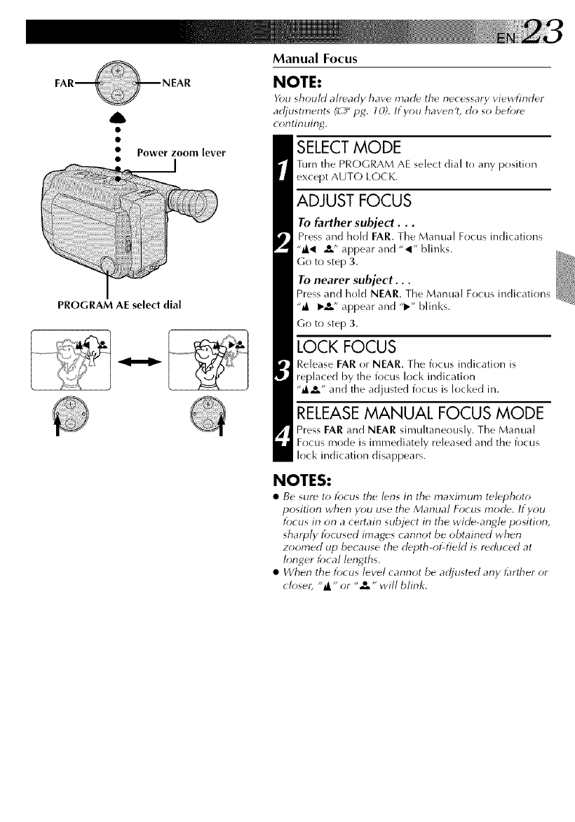
A
•Power zoom lever
•__]
PROGRAM AE seied dial
Manual Focus
NOTE:
You should already have made the necessary viewfinder
adjustments (_r__ pg. 10). If you haven't, do so befor_
continuing.
SELECT MODE
Turn the PROGRAM AE select dial to any position
except AUTO LOCK.
ADJUST FOCUS
To farther subject...
Press and hold FAR. Tile Manual Focus indications
"_1 _,t,, appear and "_I" blinks.
Go to step 3.
To nearer subject...
Press and hold NEAR. Tile Manual Focus indications
"_ I_,&" appear and "1_" blinks.
Go to step 3.
LOCK FOCUS
Release EAR or NEAR. The focus indication is
replaced by the focus lock indication
,,__o ,, and the adjusted focus is locked in.
RELEASE MANUAL FOCUS MODE
Press FAR and NEAR simultaneously. The Manual
Focus mode is immediately released and the focus
loci< indication disappears.
NOTES:
•Be sur_ to focus tile bns in the maximum telephoto
position when yuu use the Manual Focus mode. If you
focus in on a certain subject in the wide-angle position,
sharply focused images cannot be obtained when
zoomed tip because the d_pth-of-field is reduced at
longer focal lengths.
•When the focus level cannot be adjusted any t:lrther or
closer, "_" or ,e_- will blink.
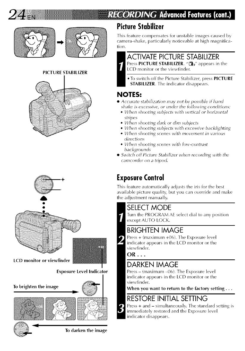
PICTURE STABILIZER
PictureStabilizer
This feature compensates for unstable irrrages caused by
camera-shake, particularly noticeable at high magnifica-
tion.
_ ACTIVATE PICTURE STABILIZER
Press PICTURE STABILIZER. "L_,/' appears in tile
LCD monitor or the viewfinder.
•To switch off tile Picture Stabilizer, press PICTURE
STABILIZER. The indicator disappears.
NOTES:
•Accurate stabilization may not be possible if hand
shake is excessive, or under the following conditions:
• When shooting subject_ with vertical or horizontal
stripes
•When shooting dark or dim subjects
• When shooting subject* with excessive backlighting
•When shooting scenes with movement in various
directions
• When shooting scenes with low-contrast
backgrounds
• Switch offPicture Stabilizer when recording with the
camcorder on a tripod.
A
LCD monitor or viewfinder
Exposure Level Indicator
To brighten the image D
ExposureControl
This feature automatically adjusts the iris for the best
available picture quality, but you can override and make
the adjustment manually.
SELECT MODE
Turn tile PROGRAM AE select dial to any position
except AUT(-) L(-)CK.
BRIGHTEN IMAGE
Press + (maximum +06). The Exposure level
indicator appears in the LCD monitor or the
viewfinder.
OR...
DARKEN IMAGE
Press- (maximum 00}. The Exposure level
indicator appears in the L(D monitor or the
viewfinder.
When you want to return to the factory setting...
RESTORE INITIAL SETTING
Press + and - simultaneously. The standard setting is
immediately restored and the Exposure level
indicator disappears.
,I
To darken the image
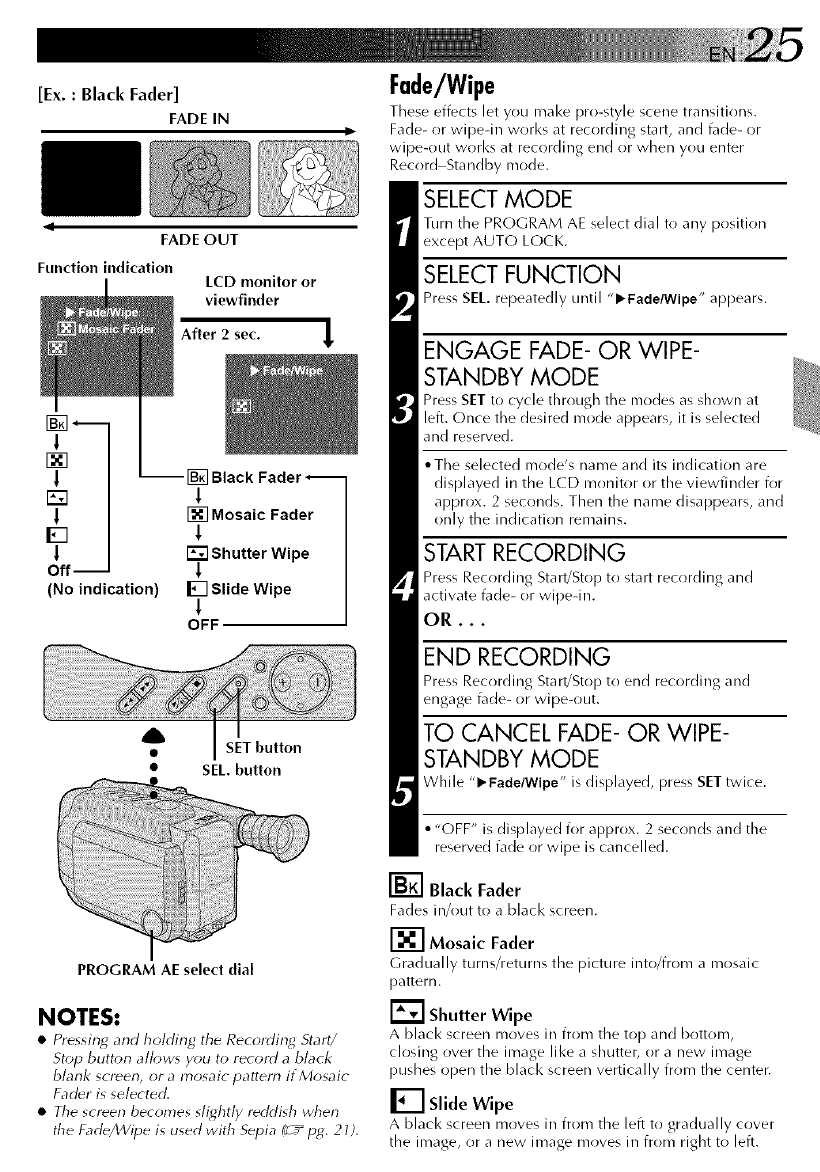
[Ex. : Black Fader]
FADE IN
FADE OUT
Function indication LCD monitor or
viewfinder
After 2 sec.
l
F_
l
[]
l
D
l
Off-
(No indication)
Black Fader--
1
[] Mosaic Fader
I
Shutter Wipe
1
I_] Slide Wipe
!
OFF
4b
• SET button
•SEL. button
PROGRAM AE select dial
NOTES:
•Pressing and holding the Recording Start/
Stop button allow, you to record a black
blank screen, or a mosaic pattern if Mosaic
Fadfr is selected.
•The screen becomes stie,htly reddish when
the Fade/Wipe is used with Sepia Pc+"p_. 21).
Fade/Wipe
These effects let you make pro-style scene transitions.
Fade- or wipedn works at recording start, and t_lde- or
wipe-out works at recording end or when you enter
Record Standby mode.
SELECT MODE
Turn the PROGRAM AE select dial to any position
except AUT(-) LOCK.
SELECT FUNCTION
Press SEL. repeatedly until "l_Fade/Wipe" appears.
ENGAGE FADE- OR WIPE-
STANDBY MODE
Press SET to cycle through the nrodes as shown at
left. Once the desired mode appears, it is selected
and reserved.
• The selected mode's name and its indication are
displayed in the LCD monitor or the viewfinder for
approx. 2 seconds. Then the name disappears, and
only the indication remains.
START RECORDING
Press Recording Start/Stop to start recording and
activate fade- or wipedn.
OR...
END RECORDING
Press Recording Start!Stop to end recording and
engage fade- or wipe-out.
TO CANCEL FADE- OR WIPE-
STANDBY MODE
While "1_ Fade/Wipe" is displayed, press SET twice.
•"OFF" is displayed for approx. 2 seconds and the
reserved fade or wipe is cancelled.
[] Black Fader
Fades in/out to a black screen.
[] Mosaic Fader
Gradually turlrs/returns the picture into/from a mosaic
pattern.
[] Shutter Wipe
A black screen moves in from the top and bottom,
closing over the image like a shutter, or a new image
pushes open the black screen vertically from the center.
[] Slide Wipe
A black screen moves in from the left to gradually cover
the image, or a new image moves in from right to left.
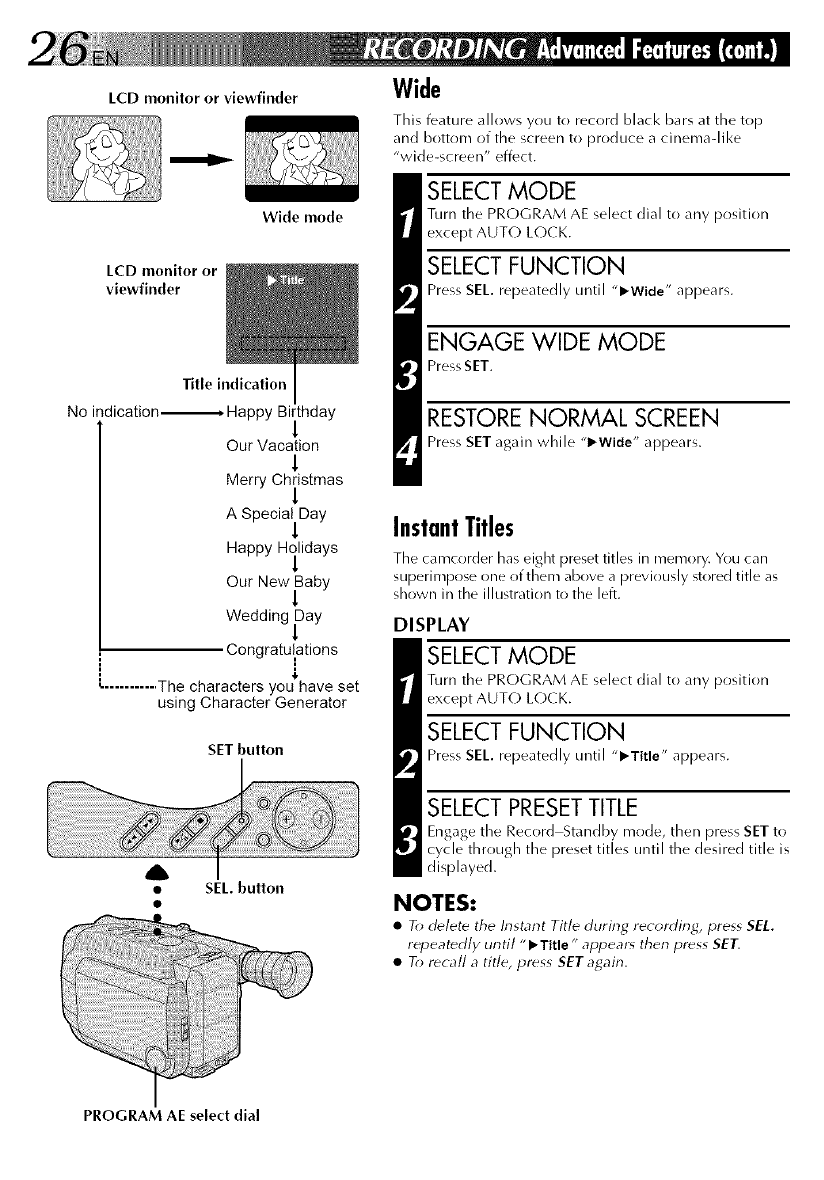
LCD monitor or viewfinder
LCD monitor or
viewfinder
Wide mode
Title indication
No indication----------------* Happy Birthday
Our Vacation
!
Merry Christmas
1
ASpecia_Day
Happy Hilidays
Our New Baby
!
Wedding fay
Congratulations
........... The characters you have set
using Character Generator
SET button
tSEL. button
PROGRAM AE select dial
Wide
This feature allows you to record black bars at the top
and bottom of the screen to produce a cinema-like
"wide-screen" effect.
SELECT MODE
Turn the PRC)GRAM AE select dial to any position
except AUTC) LC)CK.
SELECT FUNCTION
Press SE/. repeatedly until "l_Wide" appears.
ENGAGE WIDE MODE
Press SET.
RESTORE NORMAL SCREEN
Press SET again while "_-Wide" appears.
InstantTitles
The camcorder has eight preset titles in memory. You can
superimpose one of them above a previously stored title as
shown in the illustration to the left.
DISPLAY
SELECT MODE
Turn the PROGRAM AE select dial to any position
except AUT(-) L(-)CK.
SELECT FUNCTION
Press SE/. repeatedly until "l_Title" appears.
SELECT PRESETTITLE
Engage the Record Standby mode, then press SET to
cycle through the preset titles until the desired title is
displayed.
NOTES:
•To d_lete the Instant Title during recording) press SEL.
repeatedly until "l_Title" appear_ then press SET.
•To recall a title, press SET again.
A
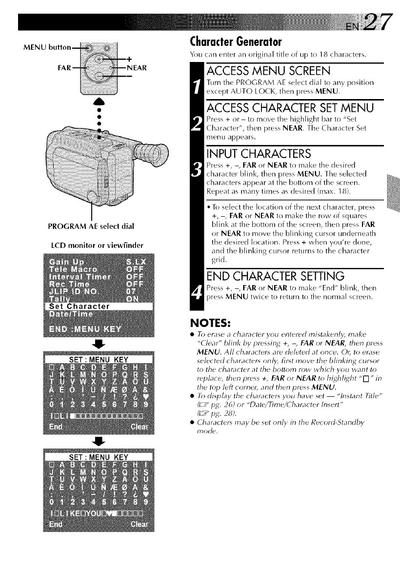
PROGRAM AE select dial
LCD monitor or viewfinder
Set Character
4!-
SET:MENU KEY
SET:MENU KEY
CharacterGenerator
You can enter an original title of up to 18 characters.
ACCESS MENU SCREEN
Turn tile PROGRAM AE select dial to any position
except AUT(-) LOCK, then press MENU.
ACCESS CHARACTER SET MENU
Press + or -to move the 11ighlight bar to "Set
( haracter", then press NEAR. The Character Set
menu appears.
INPUT CHARACTERS
Press +, -, FAR or NEAR to make the desired
character blink, then press MENU. The selected
characters appear at the bottom of the screen.
Repeat as many times as desired (max. 18).
• To select the location of the next character, press
+, -, FAR or NEAR to make the row of squares
blink at the bottom of the screen, then press FAR
or NEAR to move the blinking cursor underneath
the desired location. Press + when you're done,
and the blinking cursor returns to the character
grid.
END CHARACTER SETTING
Press +, -, FAR or NEAR to make "End" blink, then
press MENU twice to return to the normal screen.
NOTES:
•To erase a character you entered mistakenly, make
"Clear" blink by pressing +, -, FAR or NEAR, then press
MENU. All character_ are dHeted at once. Or; to erase
selected character, only, firq move the blinking cursor
to the character at the bottom row which you want to
r_place, then press +, FAR or NEAR to highlight "[q" in
the top left cornet and then press MENU.
• To display the character, you have set "Instant Title"
(__ pg. 26) or "Date/Time/Character Insert"
(_r_pg. 28).
•Character_ may be set only in the Record-Standby
rT)od_.
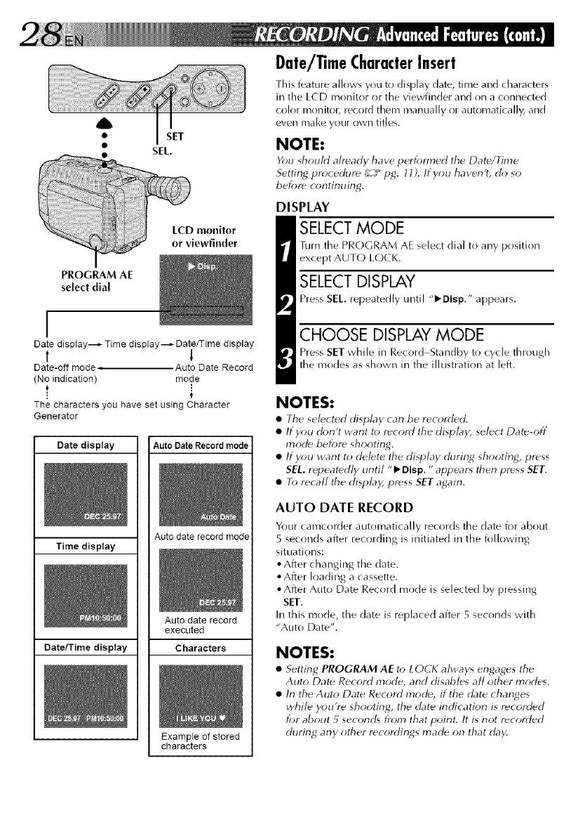
LCD monitor
or viewfinder
PROGRAM AE
select dial
I
Date dJsplay_ Time dJsplay_ Date/Time display
1 1
Date-off mode , Auto Date Record
(No indication) mode
t
The characters you have set using Character
Generater
Date display Auto Date Record mode
Time display
Auto date record mode
Auto date record
executed
Date/Time display Characters
Example of stored
characters
Date/TimeCharacterInsert
This feature allows you to display date, time and characters
in the LCD monitor or the viewfinder and on a connected
color monitol_ record them manually or automatically, and
even mal<e your own titles.
NOTE:
You should already have performed tile Dat_/Time
Setting procedur_ (_r__ pg. 11). If you haven't, do so
before continuing.
DISPLAY
SELECT MODE
Turn the PROGRAM AE select dial to any position
except AUT(-) L(-)CK.
SELECT DISPLAY
Press SEL. repeatedly until "l_Disp." appears.
CHOOSE DISPLAY MODE
Press SET while in Record Standby to cycle through
the modes as shown in the illustration at left.
NOTES:
•Tile sebcted display can be recorded.
•If you don't want to record the display, select Date-off
mode before shooting.
•If you want to delete the display during shooting/press
SEL. repeatedly until "1_ Disp. "appears then press SET.
•To recall tile display, press SET again.
AUTO DATE RECORD
Your camcorder automatically records tire date for about
5 seconds after recording is initiated in the following
situations:
•After changing the date.
•After loading a cassette.
• After Auto Date Record mode is selected by pressing
SET.
In this mode, the date is replaced after 5 seconds with
"Auto Date".
NOTES:
•Setting PROGRAM AE to LOCI( alway_ engages the
Auto Dat_ Record mode, and disables all other modes.
•In the Auto Date Record mode, if the date changes
while you're shooting/the date indication is recorded
for about 5 seconcg from that point. It is not recorded
during any other r_cordings mad_ on that day.
A
•SET
• SEL.
PROGRAM AE
select dial
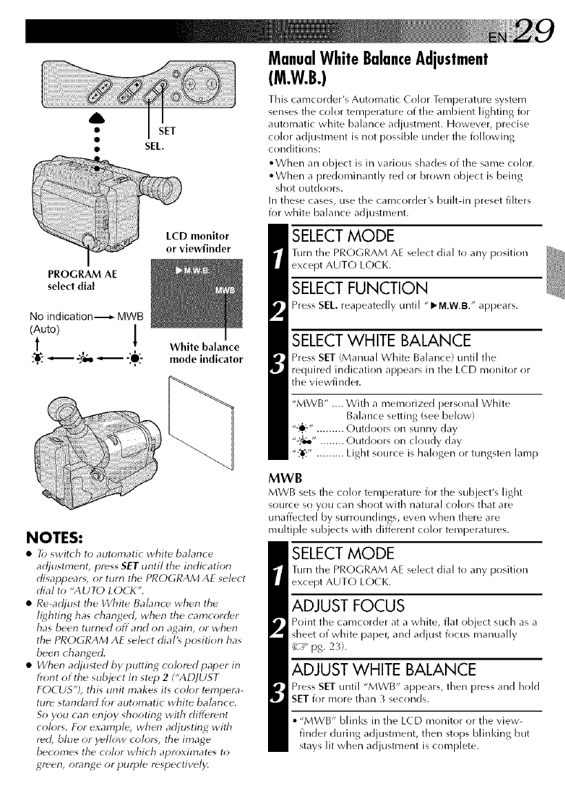
No indication._- MWB
(Auto)
t [ White balance
,n. ,n
_-£e,o_ -:,O:- mode indicator
NOTES:
•To switch to automatic white balance
adjustment, press SET until the indication
disappearg or turn the PROGRAM AE select
dial to "AUTO LOCI<".
• Re-adjust the White Babnce when the
lighting has changed, when the camcorder
has been turned off and on again, or when
the PROGRAM AE select dial's position has
been changed.
• When adjusted by putting colored paper in
front of the subject in st_p 2 ("ADJUST
FOCUS"), this unit makes its color tempera-
ture standard for automatic white balance.
So you can enjoy shooting with different
colors. For example, when adjusting with
r_d, bhle or y_llow color*, the image
becomes the color which apn>xirnates to
green, orange or purple respectively.
ManualWhiteBalanceAdjustment
(M.W.B.)
This camcorder's Automatic Color Temperature system
senses the color temperature of the ambient lighting for
automatic white balance adjustment. However, precise
color adjustment is not possible under the following
conditions:
• When an object is in various shades of the same color.
• When a predominantly red or brown object is being
shot outdor)rs.
In these cases, use the camcorder's builtdn preset filters
for white balance adjustment.
SELECT MODE
Turn the PROGRAM AE select dial to any position
except AUTO LOCK.
SELECT FUNCTION
Press SEL reapeatedly until "I_M.W.B." appears.
SELECTWHITE BALANCE
Press SET (Manual White Balance) until the
required indication appears in the LCD monitor or
the viewfinder.
"MWB" .... With a memorized personal White
Balance setting (see below)
"-:_':-"......... Outdoors on sunny day
"'_t;o" ........ Outdoors on cloudy day
":_,." ......... Light source is halogen or tungsten lamp
MWB
MWB sets tire color temperature for the subject's light
source sr) you can shoot with natural colors that are
unaffected by surroundings, even when there are
muhiple subjects with different color temperatures.
SELECT MODE
Turn the PROGRAM AE select dial to any position
except AUTO LOCK.
ADJUST FOCUS
Point the carrrcorder at a white, flat object such as a
sheet of white paper, and adjust focus manually
(_r_ pg. 23).
ADJUST WHITE BALANCE
Press SET until "MWB" appears, then press and hold
SET i_)r more than 3 seconds.
• "MWB" blinl<s in the LCD monitor or the view-
finder during_ adju tment,• then stops blinldng but
stays lit when adjustment is complete.
A
PROGRAM AE select dial
LCD monitor or viewfinder
S.LX
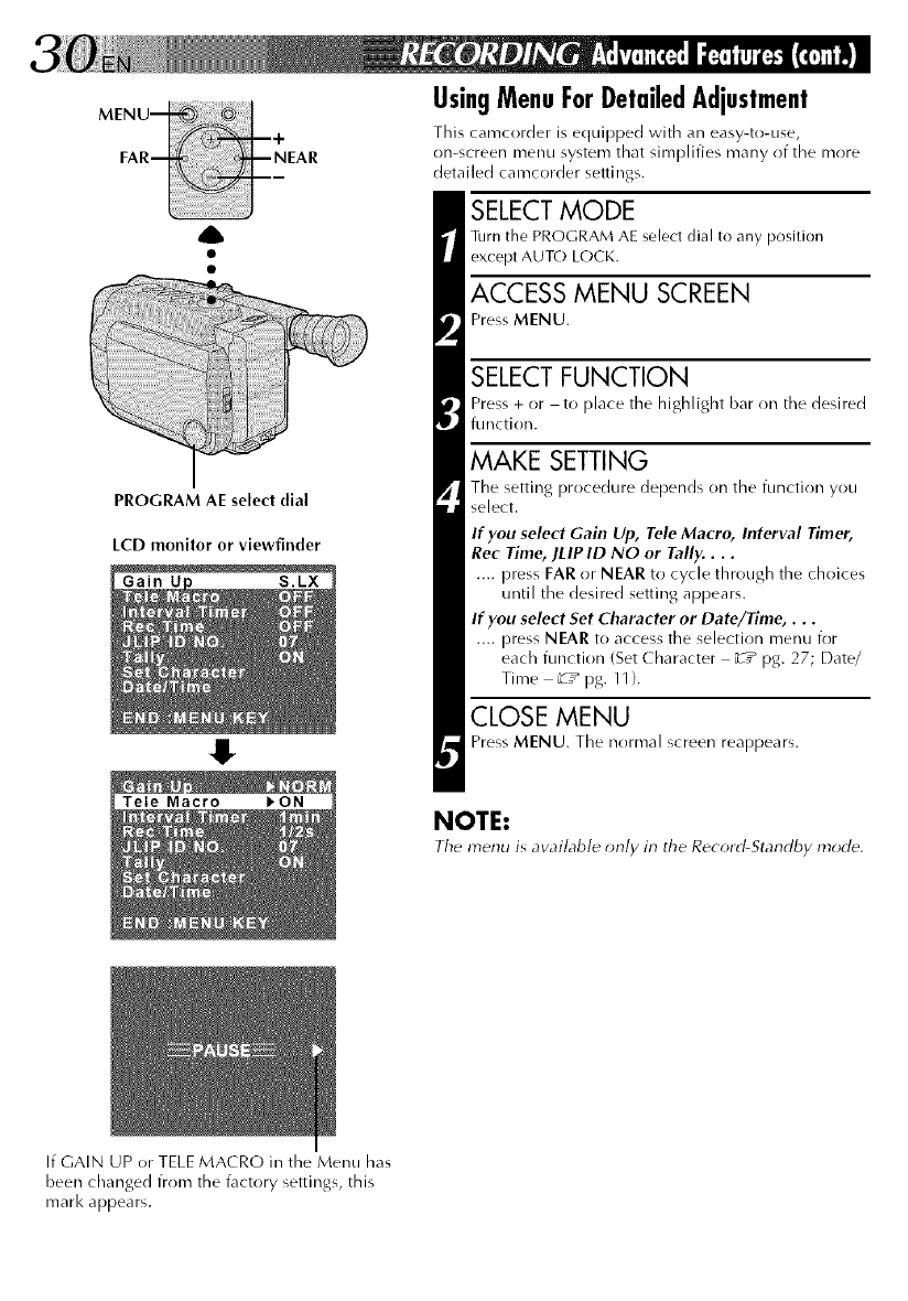
UsingMenuForDetailedAdjustment
This carncorder is equipped with an easy-to-use,
on-screen menu system that simplifies many of the more
detailed camcorder settings.
SELECT MODE
Turn the PROGRAM AE select dial to any position
except AUTO LOCK.
ACCESS MENU SCREEN
Press MENU.
SELECT FUNCTION
Press + or -to place the highlight bar on tile desired
function.
MAKE SETTING
The setting procedure depends on the function you
select.
If you select Gain Up, Tele Macro, Interval Timer,
Rec Time, ]LIPID NO or Tally....
.... press FAR or NEAR to cycle through the choices
until the desired setting appears.
If you select Set Character or Date/Time,...
.... press NEAR to access the selection menu for
each function (Set ( haracter _T_ pg. 27; Date/
Time _T_pg.11}.
CLOSE MENU
Press MENU. The normal screen reappears.
NOTE:
The menu is aw_ilable only in the Record-Standby mode.
If GAIN UP or TELE MACRO in the Menu has
been changed from the factory settings, tllis
marl< appears.
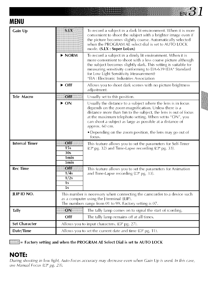
MENU
Gain Up
Tele Macro
Interval Timer
Rec Time
JLIP ID NO.
Tally
Set Character
Date/Time
iiiiiiiiiiiiiiiiiiiiiiiiiiiijiiii_ii_!_i:!i:!i:!i:!i!i_:_:iiiiiiiiiill¸¸¸
iiii
I_ NORM
I_ OFF
1_ ON
15s
30s
Imin
5min
1/4s
1/2s
ls
5s
To record a subject in a dark lit environment. When it is more
convenient to shoot the subject with a brighter image even if
the picture becomes slightly coarse. Automatically selected
when the PROGRAM AE select dial is set to AUTO LOCK
mode. (S.LX : Super LoLux)
To record a subject in a dimly lit environment. When it is
more convenient to shoot with a less coarse picture although
the subject becomes slightly dark. This setting is suitable for
measuring sensitivity conforming to EIA-639 (EIA* Standard
for Low Light Sensitivity Measurement)
*EIA : Electronic Industries Association
Allows you to shoot dark scenes with no picture brightness
adjustment.
Usually set to this position.
Usually the distance to a subject where the lens is in focus
depends on the zoom magnification. Unless there is a
distance more than lm to the subject, the lens is out of focus
at the maximum telephoto setting. When set to "ON", you
can shoot a subject as large as possible at a distance of
approx. 60 cm.
• Depending on the zoom position, the lens may go out of
focus.
This feature allows you to set the parameters for Self-Timer
(_rT_ pg. 32) and Time-Lapse recording (_rT_ pg. 33h
This feature allows you to set the parameters for Animation
and Time-Lapse recording (_rT_ pg. 33).
This number is necessary when connecting the camcorder to a device such
as a computer using the J terminal (JLIP).
The numbers range from 01 to 99. Factory setting is 07.
The tally lamp comes on to signal the start of rcording.
OFF The tally lamp remains off at all times.
Allows you to input characters. (_T* pg. 27).
Allows you to set the current date and time (_r__ pg. 11).
= Factory setting and when the PROGRAM AE Select Dial is set to AUTO LOCK
NOTE:
During_ _hooting_ in low light, Auto Focus accuracy may decrease even when Gain Up is used. In this case,
use Manual Focus (_7_pg. 2 _).
A
00 •
PROGRAM AE seJect dial
lamp
Interval Timer Indicator
Rec Time Indicator
I
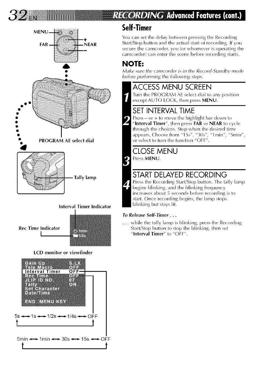
Self-Timer
You car/set the delay between pressing the Recording
Start/Stop button and the actual start of recording. If you
secure the canrcordet_ you (or whomever is operating the
canrcorder) car/enter the scene before recording starts.
NOTE:
Make sure tile camcorcl_r is in tile Rec_rd-Standby mocl_
befot_ performing tile following steps.
ACCESS MENU SCREEN
Turn the PROGRAM AE select dial to any position
except AUT(-) L(-)CK, then press MENU.
SET INTERVAL TIME
Press - or + to move the highlight bar down to
"Interval Timer", then press FAR or NEAR to cycle
through the choices. Stop when the desired time
appears. Choose from "15s", "_0s", "1 min", "5rain",
or select to turn tile function "OFF".
CLOSE MENU
Press MENU.
START DELAYED RECORDING
Press the Recording Start/Stop button. The tally lamp
begins bl inking, and the bli n king frequency
increases about 5 seconds before recording is to
start. Once recording begins, the lamp stops
blinking but stays lit.
To Release Self-Timer...
..... while the tally lamp is blinking, press the Recording
Start/Stop button to stop the blinking, then set
"Interval Timer" to "(-)FF".
LCD monitor or viewfinder
Interval Timer
5s _--_ ls _--_ 1/2s _--_ 1/4s _--_ OFF
tt
5min _--_ 1min _--_ 30s _--_ 15s _--_ OFF
t t
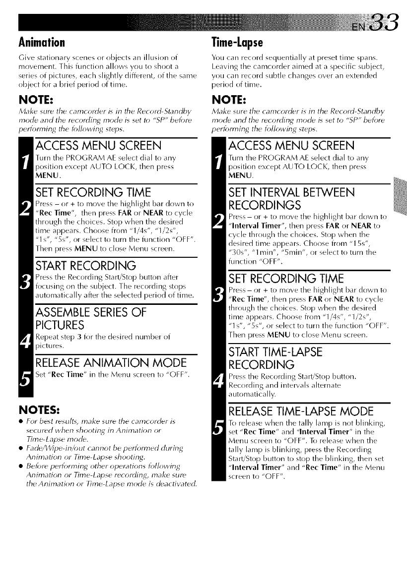
Animation
Give stationary scenes or objects an illusion of
mr)vement. This function allows you to shoot a
series of pictures, each slightly different, of the same
object for a brief period of time.
NOTE:
Make sur_ the camcorder is in the Record-Standby
mode and the recording mode is set to "SP" before
perfomffng the following steps.
ACCESS MENU SCREEN
Turn the PR(-)GRAM AE select dial to any
position except AUTO LOCK, then press
MENU.
SET RECORDING TIME
Press - or + to nrove the highlight bar down to
"Rec Time", then press FAR or NEAR to cycle
through the choices. Stop when the desired
time appears. Choose from "1/4s", "1/2s",
"1 s', "5s', or select to turn the function "(-)FF".
Then press MENU to close Menu screen.
RECORDING
'ress the Recording Start/Stop button after
focusing on the subject. The recording stops
automatically after the selected period of time.
ASSEMBLE SERIESOF
PICTURES
Repeat step 3 for the desired number of
RELEASE ANIMATION MODE
Set "Rec Time" in the Menu screen to "OFF".
NOTES:
•For best r_su!t% make sum the camcord_r is
secured when shooting in Animation or
Time-Lapse mode.
• Fade/Wipe-in/out cannot be perforated during
Animation or Time-Lapse shooting.
• Before perforn_ing other operations following
Animation or Time-Lapse recording_ make sure
the Animation or Time-Lapse mode is deactivated.
Time-Lapse
You can record sequentially at preset time spans.
Leaving the camcorder aimed at a specific subject,
you can record subtle changes over an extended
period of time.
NOTE:
Make sure the camcord_r is in the Record-Standby
mode and the recording mode" is set to "SP" before
performing the following steps.
ACCESS MENU SCREEN
Turn the PROGRAM AE select dial to any
position except AUTO L(-)CK, then press
MENU.
SET INTERVAL BETWEEN
RECORDINGS
Press- or + to move the highlight bar down to
"Interval Timer", then press FAR or NEAR to
cycle through the choices. Stop when the
desired time appears. Choose from "15s",
"X)s", "1 irrin", "5rain", or select to turn the
function "OFF".
SET RECORDING TIME
Press- or + to move the highlight bar down to
"Rec Time", then press FAR or NEAR to cycle
through the choices. Stop when the desired
time appears. Choose from "1/4s', "1/2s",
"1 s", "5s", or select to turn the function "OFF".
Then press MENU to close Menu screen.
STARTTIME-LAPSE
RECORDING
Press the Recording Start!Stop button.
Recording and intervals alternate
automatically.
RELEASE TIME-LAPSE MODE
To release when the tally lamp is not blinking,
set "Rec Time" and "Interval Timer" in the
Menu screen to "OFF". To release when the
tally lamp is blinking, press the Recording
Start/Stop button to stop the blinking, then set
"Interval Timer" and "Rec Time" in the Menu
screen to "OFF".
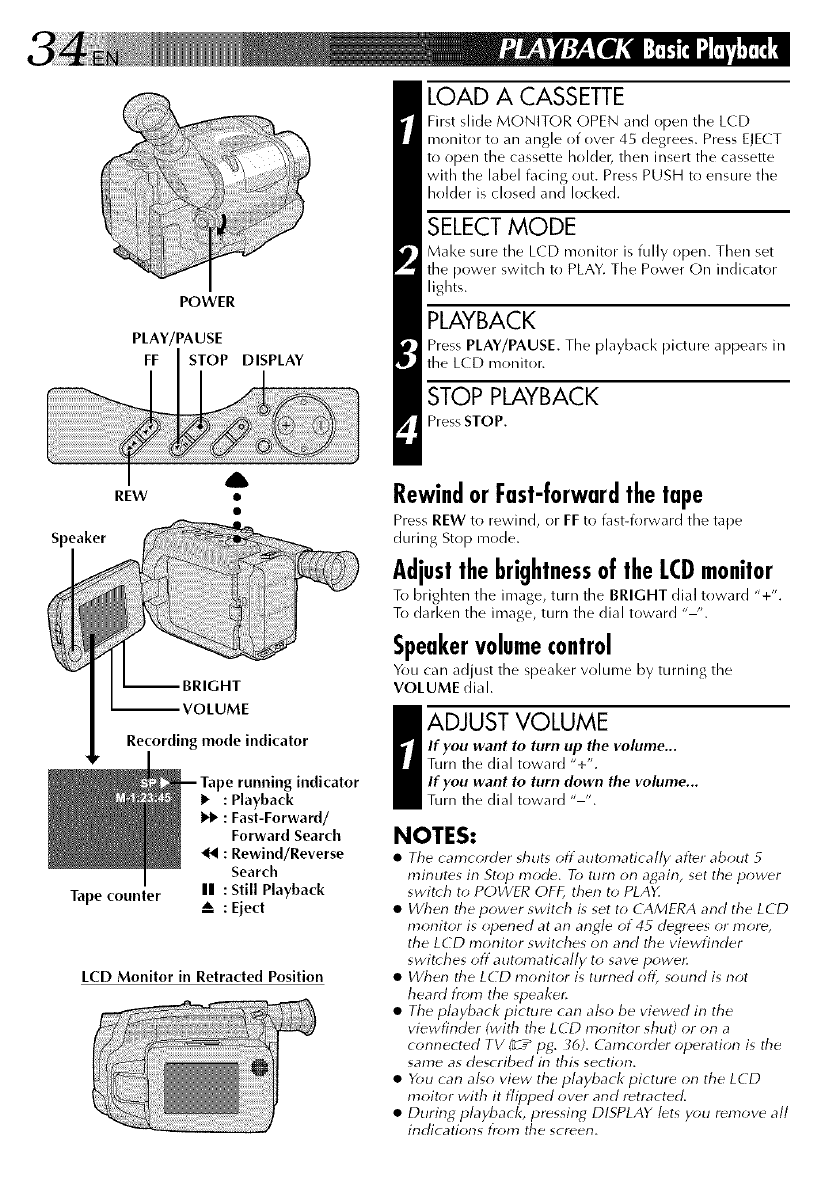
POWER
PLAY/PAUSE
FF STOP DISPLAY
A
REW •
Speaker
VOLUME
Recording mode indicator
Tape counter
indicator
•: Playback
1_ : Fast-Forward/
Forward Search
: Rewind/Reverse
Search
II : Still Playback
A: Ejed
LCD Monitor in Retracted Position
LOAD A CASSETTE
First slide MONITOR ()PEN and ()pen the LCD
monitor to an angle of over 45 degrees. Press EJECT
to open the cassette holdec then insert the cassette
with the label facing out. Press PUSH to ensure the
holder is closed and locked.
SELECT MODE
Make sure the LCD monitor is fully open. Then set
the power switch to PLAY. The Power On indicator
lights.
PLAYBACK
Press PLAY/PAUSE. The playbacl< picture appears in
the LCD monitor.
STOP PLAYBACK
Press STOP.
RewindorFast-forwardthetape
Press REW to rewind, or FF to fast-forward tile tape
during Stop mode.
AdjustthebrightnessoftheLCDmonitor
To brighten tile image, turn tile BRIGHT dial toward "+'.
To darken the image, turn the dial toward "-'.
Speakervolumecontrol
You can adjust the speaker wHume by turning the
VOLUME dial.
aADJUST VOLUME
If you want to turn up the volume...
Turn the dial toward "+".
If you want to turn down the volume...
Turn the dial toward .... .
NOTES:
•Tile camcorder shuts offaut_>n_atically after about 5
minutes in Stop mode, To turn on again, set the power
swit(h to POWFR OFF, then to PLAY.
•When tile power switch is set to CAMERA and the LCD
monitor is opened at an angle of 45 degrees or mor_,
the LCD monit{;r switches on and the viewfinder
swit( hes off automatically to save powec
•When tile LCD monitor is turned oft_ sound is not
heard from the speaker,
•The playback picture can al*o be viewed in the
viewfinder (with tile LCD monitor shut) or on a
connected TV (__pg. _6). (irmcorder operation is tile
same as described in this section.
•You can al_o view the playback picture on the LCD
moitor with it flipped over and retracted.
•During playback, pressing DISPLAY lets y_)u remove all
indications from tile screen.
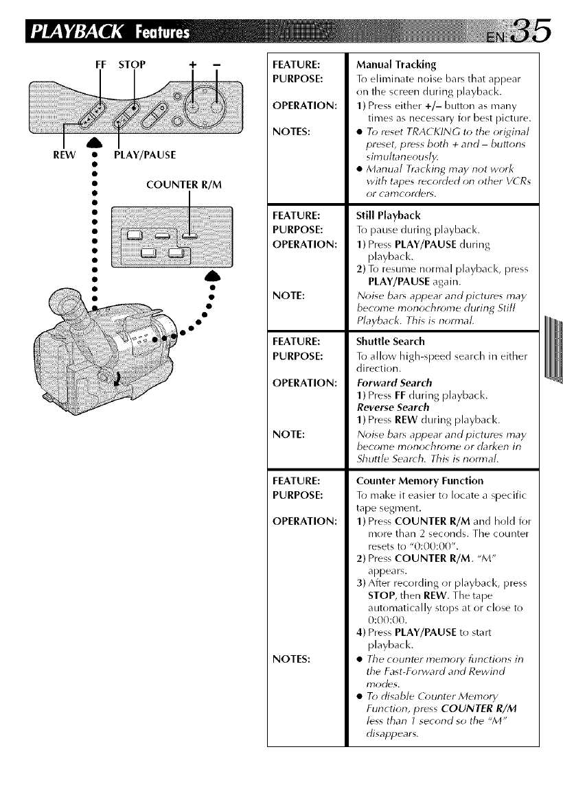
REW
FF STOP
• PLAY/PAUSE
COUNTER R/M
FEATURE:
PURPOSE:
OPERATION:
NOTES:
FEATURE:
PURPOSE:
OPERATION:
NOTE:
FEATURE:
PURPOSE:
OPERATION:
NOTE:
FEATURE:
PURPOSE:
OPERATION:
NOTES:
Manual Tracking
T(_ eliminate noise bars that appear
on the screen during playback.
1) Press either +/- button as many
times as necessary for best picture.
•To reset TRACKING to the ori_4inal
preset, press both +and -buttons
sirnultaneously.
•Manual Tracking may not work
with tapes r_corded on other VCRs
OI" calT)cold_l_,
Still Playback
TII pause during playback.
1) Press PLAY/PAUSE during
playbacl<.
2) To resume normal playbacl<, press
PLAY/PAUSE again.
Noise bars appear and pictures may
become monochrome during Still
Playback, This is normal,
Shuttle Search
To allow high-speed search in either
direction.
Forward Search
1)Press FE during playback.
Reverse Search
1)Press REW during playback.
Noise bar_ appear and pictures may
become monochrome or darken in
Shuttle Search, This is nonr_aL
Counter Memory Function
To make it easier to locate a specific
tape segment.
1) Press COUNTER R/M and hold for
more than 2 seconds. The counter
resets to "0:00:00".
2) Press COUNTER R/M. "M"
appears.
3) After recording or playback, press
STOP, then REW. The tape
automatically stops at or close to
0:00:00.
4) Press PLAY/PAUSE to start
playback.
•The counter memory functions in
the Fast-Forward and Rewind
IT)odors.
•To disable (bunter Memory
Function, press COUNTER R/M
less than I second so the _M"
disappears,
J
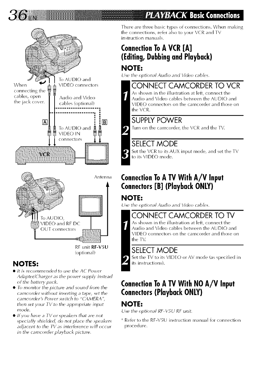
When
connecting the
cables, open
the jack cover.
To AU DI(-) and
VIDE(,) connectors
There are three basic types of connections. When making
the connections, refer also to your VCR and TV
instructi(in manuals.
ConnectionToA VCR[A]
(Editing,DubbingandPlayback)
NOTE:
Use the optional Audio and Vid(_o cabl(_s.
CONNECT CAMCORDER TO VCR
As shown in the illustration at left, connect the
Audio and Vide() cables between the AUDIO and
VIDEO connectors on the camcorder and those on
the V(R.
SUPPLY POWER
Turn on the camcorder, the VCR and the TV.
SELECT MODE
Set the VCR to its AUX input mode, and set the TV
to its VIDE(-) mode.
Antenna
RF unit RF-V5U
(optional)
NOTES:
•It is r_comrnended to use the AC Power
Adapte_/Charger as the pow(_r supply instead
of the battery pack.
•To monitor the picture and sound from the
camcordfr without inserting a tape, set the
camcorderLs Power switch to "CAMERA';
then set your TV to the appr_,priate input
• If you have a TVorspeakers that are not
specially shielded, do not place the speaker*
adjacent to the TV as interference will occur
in the camcorder playback picture.
ConnectionToATVWith A/V Input
Connectors[B] (PlaybackONLY)
NOTE:
Use the optional Audio and Video cables.
CONNECT CAMCORDER TO TV
As shown in the illustration at left, connect the
Audio and Vide() cables between the AUDI(,) and
VIDE(-) connectors on the camcorder and those on
the TV.
SELECT MODE
Set the TV to its VIDE(,) or AV mode (as specified in
its instructions).
ConnectionToATVWith NOA/V Input
Connectors(PlaybackONLY)
NOTE:
Use the optional RF_V_LJ RF unit.
* Refer to the RF-V5U instruction manual i_)r connection
procedure.
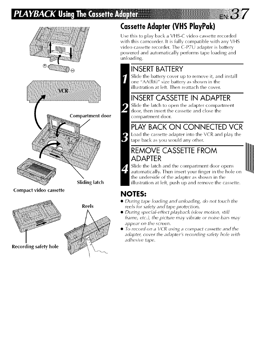
Compartment door
Compact video cassette
Slidinglatch
Reels
Recording safety hole
CassetteAdapter(VHSPlayPak)
Use this to play bacl< a VHS-( video cassette recorded
with this camcorder. It is fully compatible with any VHS
video cassette recorder, The C-P7U adapter is battery
powered and automatically performs tape loading and
unloading.
INSERT BATTERY
Slide the battery cover up to remove it, and install
one "AA(R6)" size battery as shown in the
illustration at left. Then reattach the cover.
INSERT CASSETTE IN ADAPTER
Slide the latch to open the adapter compartment
door, then insert the cassette and close the
conlpartment door.
PLAY BACK ON CONNECTED VCR
Load the cassette adapter into the VCR and play the
tape back as you would any other.
REMOVE CASSETTE FROM
ADAPTER
Slide the latch and the compartment door opens
automatically. Then insert your finger in the hole on
the underside of the adapter as shown in the
illustration at left, push up and remove the cassette.
NOTES:
•During tape loading and unloading_ do not touch tile
reels for safety and tape protection.
• During special-effect playback (@*w motion, still
flame, etc.), the pictur_ may vibrat_ or noise bar_ may
appear on the screen.
• To record on a VCR using a compact cassette and the
adapter, cover the adapter_ recording safety hole with
adhesive tape.
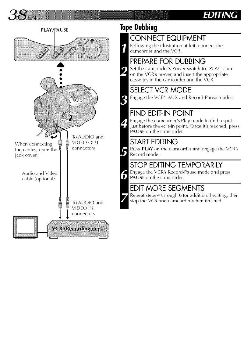
PLAY/PAUSE
To AUDIO and
When connecting VIDEO OUT
file cables, open connectors
jack cover.
Audio and Video
cable (optional)
To AUDIO and
VIDEO IN
_ _ connectors
TapeDubbing
CONNECT EQUIPMENT
Following the illustration at left, connect the
camcorder and the V(R.
PREPAREFOR DUBBING
Set the camcorder's Power switch to "PLAY", turn
on the VCR'_ power, and insert the appropriate
cassettes in the camcorder and the VCR.
SELECT VCR MODE
Engage the VCR'_ AUX and Record-Pause modes.
FIND EDIT-IN POINT
Engage the camcorder's Play mode to find a spot
just before the editqn point. Once it's reached, press
PAUSE on the camcorder.
STARTEDITING
Press PLAY on the camcorder and engage the VCR's
Record mode.
STOP EDITING TEMPORARILY
Engage the VCR's Record-Pause mode and press
PAUSE on the camcorder.
EDIT MORE SEGMENTS
Repeat steps 4 through 6 for additional editing, then
stop the VCR and camcorder when finished.
RandomAssembleEditing
[R.A.Edit]
Create edited videos easily using your
camcorder as the source player. You can select
up to 8 "cuts" for autonratic editing, in any
order you like. R.A.Edit is more easily
performed when tile optional RM-V7OOU MBR
(Multi-Brand Remote) is set to operate with
your brand of VCR (see VCR (ODE LIST), but
can also be performed by operating the V(R
manually.
CTL
RM-V7OOU (optional)
VCR CODE LIST
GE 0 0 PHILIPS 0 @
O0 O0
0 0 PANASONIC 0 0
O0 O0
HITACHI 0 0 0 0
O0 O0
JVC A 0 0 0 0
s0 0 RCA 0 0
cO0 O0
MAGNAVOX 0 0 0 0
O0 O0
O0 O0
0 0 SANYO 0 0
MITSUBISHI 0 0 0 0
0 0 SHARP 0 0
NEC 0 0 0 _)
0 0 SONY 0 0
OQ
PHILIPS 0 0 0 0
O0 O0
O0
0 0 TOSHIBA 0 0
O0 O0
0 0 ZENITH 0 0
SET REMOTE/VCR CODE
SET REMOTE TO OPERATE VCR
Turn off tile power to tile VCR and point the remote
toward the VCR's infrared sensor. Then, referring to
the VCR CODE LIST on tile left, press and hold MBR
SET, and press button (A) and then (B).
•Tile code is automatically set (>,ace you release the
MBR SET button, and tile VCR's power comes on.
OPERATE THE VCR
Make sure the VCR's power is on. Then, while
holding VCR CTL, press tile button on tile remote for
the desired function. The functions the remote can
control are PLAY, STOP, PAUSE, FF, REW and VCR
REC STBY (you don't need to press VCR CTL for this
r)n@).
You're now ready to try Random Assemble Editing.
IMPORTANT
Although the MBR is compatible with JVC VCRs and
those of many other makers, it may not work with yours
or may offer limited functions.
NOTES:
•If tile VCR's power doesn't come on in st_p 1, try
another code fr{*m tile VCR CODE LISF.
•Sorne brands ot VCR don't corne on autornatically. In
this case, turn the power on manually and try step 2.
• If the RM-V7OOU is not able to control the V('R, use
the controls on the VCR.
• Tile RM-V700U cannot be used t_) operate this
calTlcord_r,
MAKE CONNECTIONS
CONNECT TO...
[] JVC VCR EQUIPPED WITH REMOTE
PAUSE TERMINAL
Connect the editing cable to the Remote PAUSE
terminal.
[] JVC VCR NOT EQUIPPED WITH REMOTE
PAUSE TERMINAL
Connect tire editing cable to tile R.A.EDIT
cr)nnectol:
[] NON-IVC VCR WITH NEITHER
Connect the editing cable to the RM-V700Ug
Pausedn jack.
All other cr)nnections are as shown in the
illustration on [)age 40.
CONTINUED ON NEXT PAGE
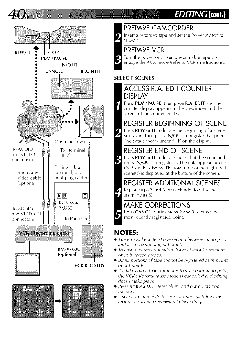
REW/FF STOP
• PLAY/PAUSE
•IN/OUT
To AUDIO
and VIDEO
out connectors
Audio and
Video cable
(optional)
To AUDIO
and VIDEO IN
cr)nnectors
To Jternrinal
flLIP)
Editing cable
(optional, o3.5
mini-plug cable)
NN []
To Remote
Y PAUSE
i
i i
{To Pausedn
RM-V700U
(optional)
VCR REc STBY
_ REPARECAMCORDER
hrsert a recorded tape and set the Power switch to
"PLAY".
PREPAREVCR
Turn the power on, insert a recordable tape and
engage the AUX mode (refer to VCR's instructions).
SELECT SCENES
ACCESS R.A. EDIT COUNTER
DISPLAY
Press PLAY/PAUSE, then Press R.A. EDIT and tile
counter display appears in the viewfinder and the
screen of the connected TV.
REGISTER BEGINNING OF SCENE
Press REW or FF to locate tile beginning of a scene
you want, then press IN/OUT to register tllat point.
The data appears under "IN" on the display.
REGISTER END OF SCENE
Press REW or FF to locate tile end oftbe scene and
press IN/OUT to register it. The data appears under
OUT on tbe display. The total time of the registered
scene(s) is displayed at the bottom of the screen.
REGISTERADDITIONAL SCENES
Repeat steps 2 and 3 for each additional scene
(as many as 8).
MAKE CORRECTIONS
Press CANCEL during steps 2 and 3 to erase the
most recently registered point.
NOTES:
•There must be at least one second between an in-point
and it, cone_ponding out-point.
•To ensure correct operation, leave at least 15 second,
open between scenes.
•Blank portions of tape cannot be registered as in-point_
or out-point_.
•If it takes more than 5 minutes to search for an in-point,
the VCR's Record-Pause mode is cancelled and editing
doesn't take place.
•Pressing R.A.EDIT clears all in-and out-points from
ITlelTloFy.
•Leave a small mal#in for error around each in-point to
ensure the scene is recorded in its entirety.
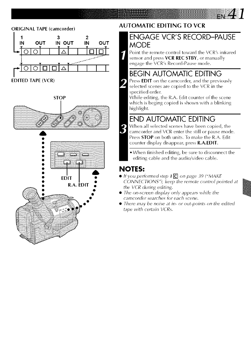
ORIGINAL TAPE (camcorder)
l 3 2
IN OUT IN OUT IN OUT
ToloTi i,,ii TDIDT
l_.io,oTD,DT,,T.--i-"i"i-i
EDITED TAPE (VCR)
STOP
AUTOMATIC EDITING TO VCR
ENGAGE VCR'S RECORD-PAUSE
MODE
Point the remote control toward the VCRk infrared
sensor and press VCR REC STBY, or manually
engage the V(R's Record-Pause mode.
BEGIN AUTOMATIC EDITING
Press EDIT on the camcorder, and the previously
selected scenes are copied to the VCR in the
specified order.
While editing, the R.A. Edit counter of the scene
which is beging copied is shown with a blinldng
highlight.
END AUTOMATIC EDITING
When all selected scenes have been copied, the
t camcorder and VCR enter the still or pause mode.
Press STOP on both units. To make the R.A. Edit
counter display disappear, press R.A.EDIT.
•• When finished editing, be sure to disconnect the
•editing cable and the audio/video cable.
•NOTES:
i EJ'T _ • /fyou peHo,med step 71-#] on page _')("MAKE
•t • CONNEdTIONS'), keep the remote control pointed at
__ • R.A. EDIT • the VCR during editing.
•_• •• • The on-_creen display only appears while the
••camcorder searches for each scene.
••There may be noise at in- or out-points on the edited
tape with certain VCRs,
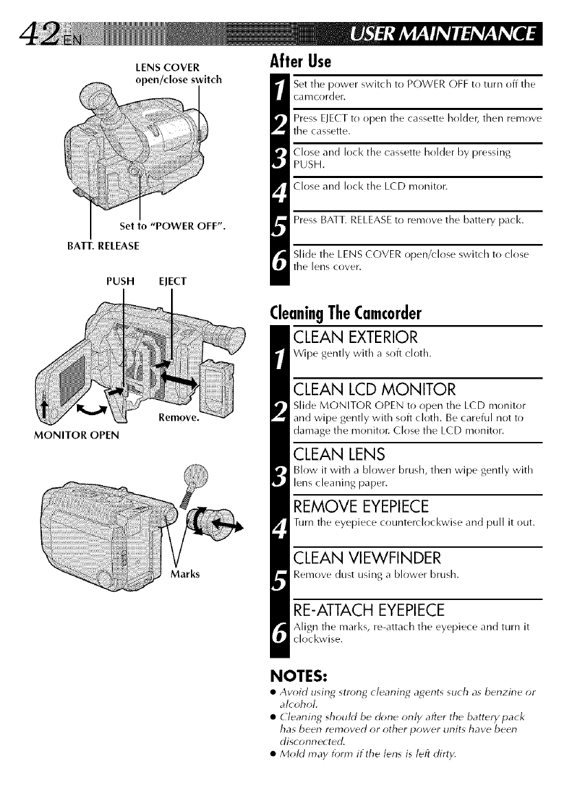
LENS COVER
Set to "POWER OFF".
BATT. RELEASE
PUSH EJECT
MONITOR OPEN
Remove.
Marks
After Use
Set the power switch to POWER OFF to turn off the
camcorder.
Press EJECT to open the cassette holder, then remove
the cassette.
Close and lock the cassette holder by pressing
PUSH.
Close and lock the LCD monitor.
Press BATT. RELEASEto remove the battery pack.
Slide the LENS COVER open/close switch to close
the lens cover.
CleaningTheCamcorder
CLEAN EXTERIOR
Wipe gently with a soft cloth.
CLEAN LCD MONITOR
Slide MONITOR OPEN to open the LCD monitor
and wipe gently with soft cloth. Be careful not to
damage the rrrr)niton Close the LCD monitor.
CLEAN LENS
Blow it with a blower brush, then wipe gently with
lens cleaning paper.
REMOVE EYEPIECE
Turn the eyepiece counterclockwise and pull it out.
CLEAN VIEWFINDER
Remove dust using a blower brush.
RE-ATTACH EYEPIECE
Align the marl<s, re-attach the eyepiece and turn it
clockwise.
NOTES:
•Avoid using str_ng cleaning agents such as benzine or
alcohol.
•Cleaning should be (k_ne only after the battery pack
has been removed or other power units have been
disconnected.
• Mold may fom} if the lens is left dirty.
No power is supplied. • The battery pack has not been attached correctly
(_rT_ pg. 8).
• The battery pack is not charged (_T_ pg. 8).
• The power supply has not been correctly connected
(_T_ pg. 9).
The power suddenly goes off and • The battery pacl< has completely discharged.
doesn't come back on by itself. • Remove the cassette and disconnect the power source,
then after a few minutes, try turning the power back on. If
it still doesn't come on, consult your nearest JVC dealer.
Recording cannot be performed.
Recording does not start.
•Tile recording tape's Erase Protection tab is missing. Cover
the hole with adhesive tape. (Some tapes have sliding
tabs. In this case, check the position of the tab.)
• The camcorder Power switch has not been set to "CAM-
ERA" (_T_ pg. 15}.
The tape is running, but there's no
playback picture.
Noise bars appear in the playback
picture.
Playback picture is blurred or
interrupted.
The counter indication is blurred
during Still playback.
•The TV has not been set to its VIDEO mode or channeh
• If A/V cr)nnection is used, the TV's VIDE(-)/TV switch has
not been set to VIDEO.
• The RF unit has not been set to the correct channel.
• Manual Tracking has not been perfr}rmed (_T_ pg. 35}.
•Tile vide{) heads are dirty or worn out. Consult your
nearest JVC dealer for head cleaning or replacement.
• This is normah
The tape stops (luring fast-forward
or rewind.
Rewinding or fast-forwarding cannot
be performed.
• Tile Counter Memory Function has been activated
(_T* pg. 35).
• Tile tape is already fully wound on one reel or tile othec
The tape won't eject.
Some functions are not available.
Vertical white lines appear when
shooting a very bright object.
Bright, crystal-shaped spots appear
in the LCD monitor and the
viewfinder.
The rear of the LCD monitor is hot.
Colored bright spots appear all over
the LCD monitor.
The indicators and the picture color
on the LCD monitor are not clear.
The LCD monitor, the viewfinder
and the lens have become dirty (ex.
fingerprints).
The picture is blurred in the Quick
Review or Retake mode.
An error number (i.e. E03) appears
in the LCD monitor or the view-
finder.
The image is out of focus.
A character generator title and the
date and time displays disappear
from the LCD monitor or the
viewfinder.
The wrong date and time are
displayed/recorded.
Even though the Lens Cover is open,
the Lens Cover Warning indicator
blinks.
•The battery pack is running low.
• If tile LCD monitor is not open over 45 degrees, EJECT
switch does not function.
• The PROGRAM AE select dial is set to "AUTO LOCK".
• This sometimes occurs when the contrast between the
bacl<ground and the object is great. It is not a defect of the
camcorder.
• Sunlight is directly entering the lens. This is not a defect of
the calrrcorder.
• The light used to illuminate the LCD monitor causes it to
be hot. Close the LCD monitor to turn it off or set tile
power switch to OFF, and let tile unit cool down.
• The LCD monitor is made with high-precision technology.
Howevec black spots or bright spots of light (red, green or
blue) may appear constantly on tile LCD moniton These
spots are not recorded on the tape. This is not due to any
defect of the unit. (Effective dots: more than 99.99 %.)
• This may occur when the surface or the edge of the LCD
monitor is pressed.
• Wipe them gently with soft cloth. Gently wipe the LCD
monitor in a semicircle because wiping strongly spreads the
stain and it won't come out easily.
• This is normal while recording in the EP mode. Some noise
may be [)resent while recording in the SP mode ('_ pg. 12).
• Turn the camcorder's power off, then disconnect the
power source. After a few minutes, try turning the power
on again. If the error number still appears in the view-
finder, consult your nearest IVC dealer.
• The diopter needs to be adjusted (_T_ pg. 10).
• The scene being shot is adversely affecting the operation
of Auto Focus (_rT_ pg. 22).
• If you remove the power source from the camcorder while
the power is on, all settings and selections are erased. ,Make
sure to turn the camcorder's power off before disconnecting
the power source.
• If you have not peri_)rmed Date/Time Setting (_rz_ pg. 11 ),
the date and time are not displayed/recorded correctly. Be
sure that Date/Time setting is carried out.
• The Lens Cover Warning indicator may blink when the
camcorder is used in dark areas, regardless of the position
of the Lens Cover.
Jhe camcorder is a microcomputer_controlled device. External noise and interference (from a TV, a radio,
etc.) might prevent it from functioning properly. In such cases, first disconnect its power supply unit
(battery pack, AC Power Adapter/Battery Chargel_ etc.) and clock battery; and then re-connect it and
proceed as usual from the beginning.
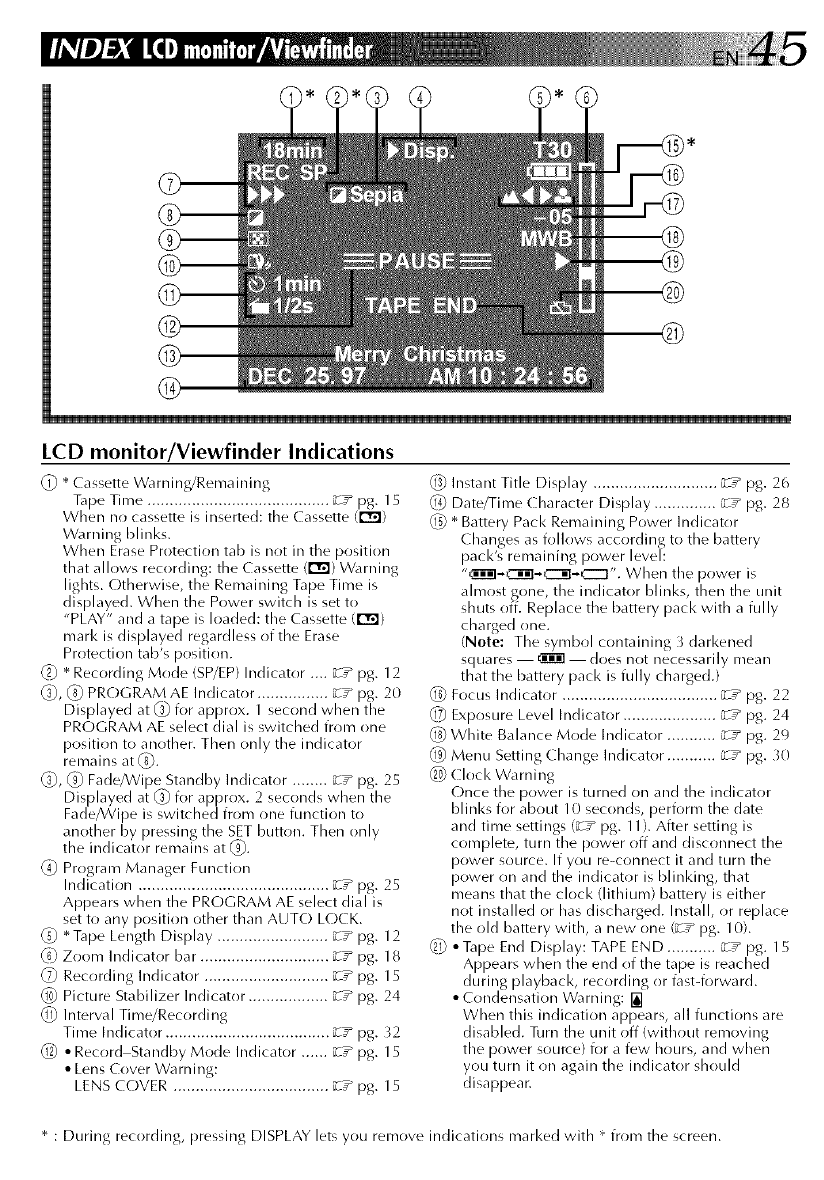
LCD monitor/Viewfinder Indications
(_ * Cassette Warning/Remaining
Tape Time ......................................... _T" P8. 15
When no cassette is inserted: the Cassette (r_)
Warning blinks.
When Erase Protection tab is not in the position
th at allows recording: the Ca ssette (r'_) Warning
lights. Otherwise, the Remaining Tape Time is
displayed. When the Power switch is set to
"PLAY" and a tape is loaded: the Cassette (r_)
mark is displayed regardless of the Erase
Protection tab's position.
_} * Recording Mode (SP/EP)Indicator .... _T_ pg. 12
_, (_) PROGRAM AE Indicator ................ _-T_ pg. 20
Displayed at _ for approx. 1 second when the
PROGRAM AE select dial is switched from one
position to another. Then only the indicator
renlains at (_.
(_, (_) Fade/Wipe Standby Indicator ........ zT_ pg. 25
Displayed at _ for approx. 2 seconds when the
Fade_Vipe is switched from one function to
another by pressing the SET button. Then only
the indicator remains at (_).
(_) Program Manager Function
Indication ........................................... "_T_ pg. 25
Appears when the PROGRAM AE select dial is
set to any position other than AUTO LOCK.
_} * Tape Length Display ......................... ;rT_ pg. 12
Zoom Indicator bar ............................. _T_ pg. 18
_7_ Recording Indicator ............................ _T_ pg. 15
Picture Stabilizer Indicator .................. ;rT_ pg. 24
Interval Time/Recording
Time Indicator ..................................... _T_ pg. }2
• Record Standby Mode Indicator ...... _T_ pg. 15
• Lens Cover Warning:
LENS COVER ................................... ;rT_ pg. 15
Instant Title Display ............................ "_T_ pg. 26
Date/Time Character Display .............. _rT_ pg. 28
_ * Battery Pacl< Remaining Power Indicator
Changes as follows according to the battery
pack's remaining power level:
"_._'-iil._._". When the power is
ahnost gone, the indicator blinks, then the unit
shuts off. Replace the battery pack with a fully
charged one.
(Note: The symbol containing 3 darkened
squares i does not necessarily mean
that the battery pack is fully charged.)
Q_ Focus Indicator ................................... _T _ pg. 22
_7_ Exposure Level Indicator ..................... ;rT" pg. 24
{_) White Balance Mode Indicator ........... _T _ pg. 29
_9} Menu Setting Change Indicator ........... ;rT" pg. 30
_ Clock Warning
Once the power is turned on and the indicator
blinks i2)r about 10 seconds, perform the date
and time settings (_T _ pg. 11). After setting is
complete, turn tbe power off and disconnect the
power source. If you re-connect it and turn the
power on and the indicator is blinking, that
means that the clock (lithium) battery is either
not installed or has discharged. Install, or replace
the old battery with, a new one (_rT_ pg. 10).
_ * Tape End Display: TAPE END ........... _T _ pg. 15
Appears when the end of the tape is reached
during playback, recording or fast-forward.
•Condensation Warning:
When this indication appears, all functions are
disabled. Turn the unit off (without removing
the power source} for a few hours, and when
you turn it on again the indicator should
disappear.
* : During recording, pressing DISPLAY lets you remove indications marl<ed with * from the screen.
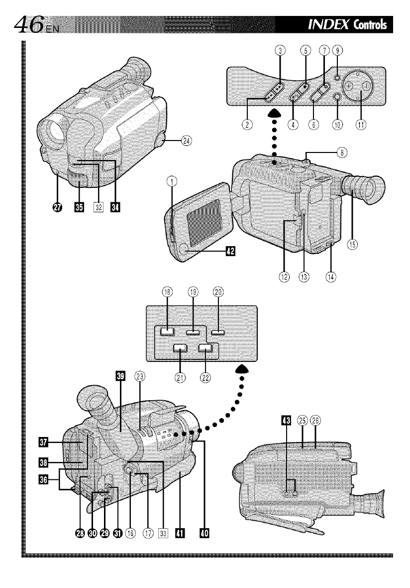
Controls
(_) MONITOR OPEN Switch .................... _T_ pg. 16
_) REW Button ....................................... _;; pg. 34
RETAKE R [Quick Review] Button ....... _rT_ pg. 19
FF Button ........................................... _rT_ pg. 34
RETAKE F Button ................................ _rT_ pg. 19
(_) PLAY/PAUSE Button ........................... _rT_ pg. 34
_) STOP Button ...................................... _T_ pg. 34
_) SEE. Button ........................................ "_T_ pg. 25
_7) SET Button ......................................... _T_ pg. 25
(_ Power Zor}m Lever ............................ _T_ pg. 18
(_) DISPLAY Buttr}n ................................. _r;_ pg. 15
MENU Button .................................... _rT_ pg. 30
1_)Multi-Function Control
• Exposure +_ ................................... _r;_ pg. 24
• Focus FAR/NEAR ............................. _;_ pg. 22
• Menu Setting Change ....................... _T_ pg. 30
• Tracking +_ .................................... _r;_ pg. 35
(_) PUSH Button ..................................... _r;_ pg. 13
(_) ELECTSwitch ...................................... _r;_ pg. 13
Q_4)BATT. [Battery] RELEASESwitch ......... "_;_pg. 8
fig) Diopter Adjustment ............................ _T_ pg. 10
(_ Recording Start/Stop Button ................ _T_ pg. 15
_ POWER Switch .............................. _r;_ pg.15, 34
O_pRecording Mode [SP/EP] Select
Button ................................................ _;_ pg. 12
R.A.EDIT CANCEL Button ................... _rT_ pg. 40
_) R.A.EDIT IN/OUT Button .................... _rT_ pg. 40
60_Tape Length ]T2B•30,40]
Select Buttr)n ...................................... _Z_ pg. 12
COUNTER R [Reset]/M ]Memory[
Button ................................................ _rz_ pg. 35
61) EDIT Button ....................................... _rz_ pg. 41
62) R.A.EDIT Button ................................. _rZ_ pg. 40
6S)PICTURE STABILIZER Button .............. _rT_ pg. 24
64) PROGRAM AE Select Dial .................. _z_ pg. 20
BRIGHT Dial ..................................... "_T_ pg. 34
66) VOLUME Dial ................................... "_T_ pg. 34
Connectors
1_ l terminal (JLIP(Joint Level Interface Protocol)
Connector.)
(Located beneath the jack cover)
• Connect the Editing Cable when perik)rming
Random Assemble Editing {_r__ pg. 40).
• It is used to connect the camcorder to a device
such as a personal computer.
For further detail consult your nearest IV(-
dealen
_) D( IN Jack ......................................... _-T_ pg. 9
The jacks !_ to t_ are located beneath the jack
cover.
_) VIDEO OUT Jack ............................... _rT_ pg. 36
_) RF DC OUT lack ................................ _rT_ pg. 36
_} AUDIO OUT lack .............................. _T_ pg. 36
Indicators
[] Tally Lamp ......................................... "_T_ pg. 15
[] Power On Indicator ........................... ;rT_ pg. 15
Other Parts
[_llCamera sensor
Be careful not to cover this area; built-in
here is the sensor necessary for shooting.
[] Microphone
[] Shoulder Strap Eyelets ........................ _r__ pg. 14
[] Clock Battery Compartment ................ ;rz_ pg. 1B
[] Battery Pack Mount ........................... ;rz_ pg. 8
[] Electronic Viewfinder ......................... _z" pg. 10
[] LENS COVER Switch ......................... "_z"pg. 15
[] Grip Strap .......................................... "_z"pg. 14
[] Speaker .............................................. "_z"pg. 34
[] Tripod Mounting Socket ...................... _r__ pg. 14
A
AC Power Adapter .................................. pg. 8
Animation Recording .............................. pg. 33
Auto Date Record ................................... pg. 28
Auto Focus ............................................. pg. 22
Auto Mode Lock Mode ........................... pg. 21
Auto Mode Release Mode ....................... pg. 21
B
Battery Pack ............................................ pg. 8, 49
Brighten the Image .................................. pg. 24
C
Car Battery .............................................. pg. 9
Cassette Adapter ..................................... pg. 37
Character Generator ............................... pg. 27
Charge Marker ........................................ pg. 9
(harging the Battery Pack ........................ pg. 8
(lock (Lithium) Battery ........................... pg. 10
Connection to a VCR/TV ........................ pg. 36
Contents ................................................. pg. 7
Counter Memory .................................... pg. _5
D
Darken the Image ................................... pg. 24
Date/Time/(haracter Insert ...................... pg. 28
Date/Time Setting ................................... pg. 11
Discharge the Battery pack ...................... pg. 8
Diopter Adjust ........................................ pg. 10
E
Electronic Fog Filter Mode ....................... pg. 21
EraseProtection ...................................... pg. 13
Exposure Control .................................... pg. 24
F
Fade-in/out ............................................. pg. 25
Fast-Forward Tape ................................... pg. 34
Focus Lock ............................................. pg. 22
G
Grip Adjustment ..................................... pg. 14
H
High Speed Shutter Mode ........................ pg. 21
I
Insert Cassette ......................................... pg. 13
Instant Titles ............................................ pg. 26
L
LCD monitor/Viewfinder, indications ....... pg. 45
I
Journalistic shooting ............................... pg. 17
M
Manual Focus ......................................... pg. 23
MBR Code Setting ................................... pg. _9
N
ND Effect Mode ...................................... pg. 21
P
Picture Stabilizer ..................................... pg. 24
Playbacl< ................................................. pg. 34
Program AE with Special Effects ............... pg. 20
Provided Accessories .............................. pg. 6
Q
Quick Review ......................................... pg. 18
R
Random Assemble Editing ....................... pg. 39_il
Recording, Advanced Features ................ pg. 20 33
Recording ............................................... pg. 15
Recording, Start/Stop .............................. pg. 15
Recording Mode Setting ......................... pg. 12
Recording-Standby ................................. pg. 15
Remote Control Unit ............................... pg. _9
Remove Cassette ..................................... pg. 13
Retake ..................................................... pg. 18
Rewind Tape ........................................... pg. _4
S
Self-Timer ............................................... pg. 32
Sepia Mode ............................................ pg. 21
Shoulder Strap Attachment ...................... pg. 14
Shuttle Search ......................................... pg. _5
Specifications ......................................... pg. 55
Sports Mode ........................................... pg. 21
Still Playback .......................................... pg. _5
T
Tape Counter .......................................... pg. _4
Tape Dubbing ......................................... pg. _8
Tape Length Setting ................................. pg. 12
Time-Lapse Shooting ............................... pg. 33
Tracking .................................................. pg. 35
Tripod Mounting ..................................... pg. 14
Twilight Mode ......................................... pg. 21
V
Viewfinder Adjustment ........................... pg. 10
W
White Balance Adjustment ...................... pg. 29
Wide Mode ............................................. pg. 26
Z
Zooming ................................................. pg. 18

When using the AC Power Adapter/Charger in
areas other than the USA
• The provided AC Power Adapter/(harger features
automatic voltage selection in the AC range from
110 Vto 240 V.
USING HOUSEHOLD AC PLUG ADAPTER
Ill case of connecting tire unit's power cord to an
AC wall outlet other than American National
Standard C73 series type use an A( plug adapter,
called a "Siemens Plug", as shown.
For this AC plug adaptel, consuh your nearest iV(
dealer.
Plug adapter
INFORMATION
This device complies with Part 15 of FCC Rules.
Operation is subject to the following two ermdi-
:ions:
(1) This device may not cause harmful interference,
and (2) this device must accept any interference
received, including interference that may cause
undesired operation. Change or mr)difications not
approved by the party responsible for compliance
could void the user's authority to operate the
equipment. This equipment has been tested and
found to comply with the limits for a Class B digital
device, pursuant to Part 15 of the FCC Rules. These
limits are designed to provide reasonable protectirm
against harmful interference in a residential
installation. This equipment generates, uses, and
can radiate radio frequency energy and, if not
installed and used in accordance with the instruc_
tions, may cause harmful interference to radio
communications. HoweveB there is no guarantee
that interference will not occur in a particular
installation. If this equip me nt does ca use harmful
interference to radio or television reception, which
can be determined by turning the equipment off
and on, the user is encouraged to try to correct the
interference by rme or mr)re of the following
measures:
Reorient or relocate the receiving antenna.
Increase the separation between the
equipment and receivec
Connect the equipment into an outlet on a circuit
different from that to which the receiver is
crmnected.
Consuh the dealer or an experienced radio/TV
technician i_)r help.
General Battery Precautions
• When the C-P6U or C-P7U (cassette adapter) is not
functioning even when correctly operated, the battery
is exhausted. Replace it with fresh one.
• Use only the following batteries:
C-P6U or C-P7U ........................ AA (R6) size
Please make note of the following rules for battery use.
When misused, battery can leak or explode.
1. Refer to the C-P6U/C-P7U instructions when
replacing the battery.
2. Do not expose the battery to excessive heat as it can
leak or explode.
3. Do not dispose of battery in a fire.
4. Remove battery from the unit if it is to be stored for
an extended period to avoid battery leakage which
can cause malfunctions.
Battery Packs
The supplied battery pack is a
nickel-cadmium battery. Before using
the supplied battery pack or an optional
battery pack, be sure to read the
following cautions:
1. To avoid hazard...
..... do not burn.
..... do not short-circuit the terminals. Termil
..... do not modify or disassemble.
..... use only specified chargers.
2. To prevent damage and prolong service life...
..... do not subject to unnecessary shock.
..... avoid repeated charging without fully discharg-
ing.
..... charge in an environment where
tenlperatures are within the tolerances shown in
the chart below. This is a chemical reaction type
battery--cooler temperatures impede chemical
reaction, while warmer temperatures can
prevent complete charging.
..... store in a cool, dry place. Extended exposure to
high temperatures will increase natural
discharge and shorten service life.
..... avoid prolonged uncharged storage.
..... remove from charger or powered unit when not
in use, as some machines use current even
when switched off.
3. To prevent damage to the camcorder...
..... replace the battery pack when it begins to
deliver less recording time per charge.
NOTE:
It is normal for the battery pack to be warm after
charging, or after use.
Temperature Range Specifications
Charging ...................................... 10°C to 35°C
Operation .................................... 0°C to 40°C
Storage ......................................... 10°C to 30°C
NOTES:
•Recharging time is based on r_om temperature of
20°C.
• The lower the temperature, the longer recharging
takes.
Cassefles
To properly use and store your cassettes, be sure to read
the following cautions:
1. During use...
..... make sure the cassette bears the VHS-C mark.
..... be aware that recording onto prerecorded tapes
automatically erases the previously recorded
video and audio signals.
..... make sure the cassette is positioned properly
when inserting.
..... do not load and unload the cassette
repeatedly without allowing the tape to run at
all. This slackens the tape and can result in
damage.
..... do not open the front tape cover. This exposes
the tape to fingerprints and dust.
2. Store cassettes...
..... away from heaters or other heat sources.
..... out of direct sunlight.
..... where they won't be subject to unnecessary
shock or vibration.
..... where they won't be exposed to strong nlagnetic
fields (such as those generated by motors,
transforrners or nlagnets).
..... vertically, in their original cases.
Main Unit
1. For safety, DO NOT...
..... open the camcorder's chassis.
..... disassemble or modify the unit.
..... short-circuit the terminals of the battery pack.
Keep it away from metallic objects when not in
LISe.
..... allow inflamrnables, water or metallic objects to
enter the unit.
..... remove the battery pack or disconnect the
power supply while the power is on.
..... leave the battery pack attached when the
carncorder is not in use.
2. Avoid using the unit...
..... in places subject to excessive hunlidity or dust.
..... in places subject to soot or steam such as near a
cooking stove.
..... in places subject to excessive shock or vibration.
..... near a television set.
..... near appliances generating strong magnetic or
electric fields (speakers, broadcasting antennas,
etc.).
..... in places sub ect to extremely high (over 40°C
or 104°F) or extreme y ow (under 0°C or 32°F)
temperatures.
3. DO NOT leave the unit...
..... in places of over 50°C (122°F).
..... in places where humidity is extremely low
(beklw 35%) or extrernely high (above 80%).
..... in direct sunlight.
..... in a closed car in summer.
..... near a heater.
4. To protect the unit, DO NOT...
..... allow it to becorne wet.
..... drop the unit or strike it against hard objects.
..... subject it to shock or excessive vibration during
transportation.
..... keep the lens directed at extremely bright
ob ects for long periods.
..... (irect tie eyepiece of tie viewfinder at tie sun.
..... carry it by holding the viewfinder or the LCD
monitor. Be sure to hold the main unit with both
hands or use the grip.
..... swing it excessively when using the shoulder
strap.
5. This camcorder features a built-in head cleaner
which automatically cleans the heads and head
drum when a cassette is loaded or unloaded. If,
however, the heads become dirty and cause
blurriness or interruption in the playback
picture, consult your nearest JVC dealer.
LCD monitor
1. To prevent damage to the LCD monitor, DO
NOT...
..... push it strongly or apply any shocks.
..... place the camcorder with the LCD monitor on
the bottom.
2. To prolong service life...
..... avoid rubbing it with coarse cloth.
3. Make be aware of the following phenomena for
LCD monitor use. These are not mulfunctions ....
•While using the camcorder, the surface around tile
LCD monitor and/or the back of the LCD monitor
may heat up.
• If you leave power on for a long time, the surface
around the LCD monitor beconles hot.
About moisture condensation...
• You have observed that pouring a cold liquid
into a glass will cause drops of water to fore/on
the glass' outer surface. This same phenomenon
occurs on the head drum of a camcorder when it
is nloved from a cool place to a warm place,
after heating a cold room, under extremely
humid conditions or in a place directly subjected
to the cool air from an air conditioner.
• Moisture on the head drurn can cause severe
damage to the video tape, and can lead to
internal damage to the camcorder itself.
Serious malfunctioning
If malfunctioning occurs, stop using the unitinmlediately and consult your local JVC dealer.
GENERAL
Format
P o'vve r source
Power consumption
LCD monitor off,
viewfinder on
LCD monitor on,
viewfinder off
Signal system
Vide() recording system
Luminance
Colr)r
Cassette
Tape speed
SP
EP
Recording time (max.}
SP
EP
Operating temperature
Operating humidity
Storage temperature
Weight
Dimensions
(Including viewfinder)
CAMERA
Pick up
Lens
Viewfinder
White balance
adjustment
LCD MONITOR
Size
LCD system
VIDEO
Output
: VHS NTS( standard
: DC 6V
:6.5W
:6.9W
: NTSC-type
: FM recording
: Converted sub-carrier
direct recording
Conforms to VHS
standard
: _ cassette
: _3.35 mm/sec.
(1-5/16 ips)
: 11.12 mm/sec. (7/16 ips)
: 40 minutes
: 120 minutes
(with TC-40 cassette)
: 0C to +40C
(32% to 104%)
: _5% to 80%
:20°C to +S0°C
(-4°F to 122°F)
: Approx. 1030 g (2.3 Ibs)
: 118 (W) x 115 (H) x
231 (D} mm (4-11/16" x
4-9/16" x 9-1/8")
: 1/4" format CCD
: F1.6, f = 3.8 to 68.4 ram,
18:1 power zoom lens
with auto iris and macro
control, filter diameter
46 mm
: Electronic viewfinder
with 0.5" black/white
C RT
:Auto/Manual adjustment
: 3" diagonally measured
: LCD/TFT active matrix
system
: 1 Vp-p, 75 ohms,
unbalanced (via VIDE(-)
out connector)
AUDIO
Output
Speaker
: 8 dBs, 1 I<-ohm
(via AU DI(-) {)tit
connector)
: 20 mm round x 1,
1310 nau raI
AC POWER ADAPTER/BATTERY CHARGER
(AA-V11 U)
P(}wer req U i renlent
U.S.A. and Canada
Other countries
Power consumption
Output
Charge
VTR
Charging system
Dinlensions
:AC 120 VQ,, 60 HZ
:AC110Vto240V'-v,
50/6(} Hz
:23W
: DC 8.5 V --'==,1.3 A
: DC 6.3 V --'==,1.8 A
:C(}nstant current, peak
detecti(}n, timer
controlled
: 150 (W) x 42 (H) x
68 (D) mm (5-15/16" x
1-11/16" x 2-11/16")
Weight :Approx. }20 g (0.71 Ibs)
CASSETTE ADAPTER (C-P7U)
Dimensions : 188 (W) x 25 (H) x
104 (D) mm (7-7/16" x 1"
x 4-1/8")
Weight :Appr()x. 240 g (0.5} Ibs)
Accessory :"AA (R6)"-size battery x 1
Provided Accessories ...................... _m°pg. 6
Optional Accessories
• Battery Packs BN-V12U, BN-V22U, BN-V25U
•Car Battery Charger BH-V3U
• Battery Charger BH-VC10U
•Car Battery Cord AP-V7U
•RF Unit RF-V5U
•Compact VHS-C Cassettes TC-40/30/20
•Active Carrying Bag CB-V7U
•Wireless Remote Control Unit RM-V700U
The RM-V70{}U cannot be used to operate this
camcorder.
This camcorder can use the RM-V700U only for
R.A. Edit with a n(}n-IVC VCR.
Some acccessories are not available in s(}me areas.
Please consult y(}ur nearest JVC dealer i2)r details on
accessories and their availability.
Specifications shown are for SP rood{ _unless
otherwise indicated. E. & O. E. Desi_4n and
specifications subject to change without notice,
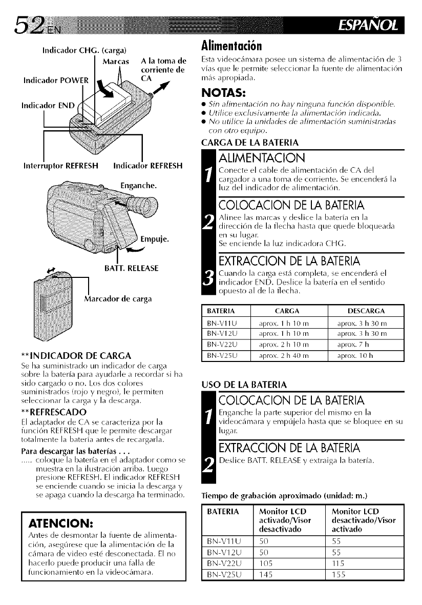
Indicador CHG. (carga)
Marcas
Indicador POWER
Ala toma de
corriente de
Indicador END
Interruptor REFRESH Indicador REFRESH
Enganche.
BATT. RELEASE
Marcador de carga
**INDICADOR DE CARGA
Se ha suministrado un indicador de carga
sobre la baterfa para ayudarle a recordar si ha
sido cargado o no. Los dos colores
suministrados (rojo y negro}, le permiten
seleccionar la carga y la descarga.
** REFRESCADO
El adaptador de CA se caracteriza por la
funci6n REFRESHque le permite descargar
totalmente la baterfa antes de recargarla.
Para descargar las baterias...
..... coloque la bateria en el adaptador como se
muestra en la ilustraci6n arriba. Luego
presione REFRESH.El indicador REFRESH
se enciende cuando se inicia la descarga y
se apaga cuando la descarga ha terminado.
ATENClON:
Antes de desmonta r la fuente de a limenta-
ci6n, asegQrese que la alimentaci6n de la
cilmara de video est6 desconectada. El no
hacerlo puede producir una falla de
funcionamiento en la videoclunara.
Alimentaci6n
Esta videoc_mlara posee un sistema de alimentaci(m de 3
vLls que le pem/ite sdeccionar la fi_ente de alimentaci6n
m_s apropiada.
NOTAS:
•Sin alimentaci6n no hay ninguna funciE_n disponible,
•Uti!ice exc!usiw_mente !a a!imentaci6n indicada.
•No utilice la unidades de alimentacidn suministradas
con otto) equipo.
CARGA DE LA BATERIA
ALIMENTACION
Conecte el cable de alimentaci6n de CA del
cargador a una toma de corriente. Se encender4 la
luz del indicador de alimentaci6n.
COLOCACION DE LA BATERIA
Alinee las marcas y deslice la baterfa en la
direcci6n de la flecha hasta que quede bloqueada
en su lugar.
Se enciende la luz indicadora CHG.
EXTRACCION DE LA BATERIA
Cuando la carga est_ completa, se encenderi_ el
indicador END. Deslice la baterfa en el sentido
opuesto al de la flecha.
BATERIA CARGA DESCARGA
BN-V11U aprox. I h 10 maprox. 3 h 30 m
BN-V12U aprox. I h 10 m aprox. 3 h 30 m
BN-V22U aprox. 2 h 10 m aprox. 7 h
BN-V25U aprox. 2 h 40 m aprox. 10 h
USO DE LA BATERIA
COLOCACION DE LA BATERIA
Enganche la parte superior del mismo en la
videocilmara y empQjela hasta que se bloquee en su
lugar.
EXTRACCION DE LA BATERIA
Deslice BATT. RELEASE y extraiga la baterfa.
Tiempo de grabad6n aproximado ( midad: m.)
BATERIA Monitor LCD Monitor LCD
activado/Visor desactivado/Visor
desadivado activado
BN-V11U 50 55
BN-V12U 50 55
BN-V22U 105 115
BN-V25U 145 155
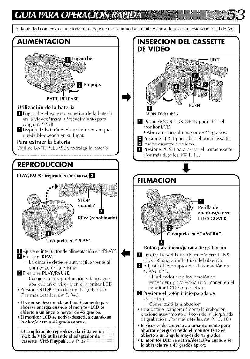
I Si la unidad comienza a funcionar real, deje de usarla inmediatamente y consulte a su concesionario local de IVC.
"ALIMENTACION
BATT. RELEASE
anche.
Empuje.
Utilizaci6n de la bateria
[] Enganche el extremo superior de la bateria
en la videocAmara. (Procedimiento para
carga: _T_ P. 8}
[] Empuje la baterfa hacia adentro hasta que
quede bloqueada en su lugar.
Para extraer la bateria
Deslice BATT. RELEASE y extraiga la baterfa.
'REPRODUCCION
PLAY/PA USE (reproducci6n/pausa) |
..IP
[] Ajuste el interruptor de alimentaci6n en "PLAY'
[] Presione REW.
La cinta se detiene autom_iticamente al
comienzo de la misma.
[] Presione PLAY/PAUSE.
Comienza la reproducci6n y la imagen
aparece en el visor o en el monitor LCD.
• Presione STOP para detener la grabaci6n.
(Por m_is detalles, "iT* p. 34.)
• El visor se desconecta autom4ticamente para
ahorrar energia cuando el monitor LCD es
abierto a un 4ngulo mayor de 45 grados.
• El monitor LCD se activa/desactiva cuando se
Io abre/cierre a 45 grados aprox.
O simplemente reproduzca la cinta en Un
VCR tie VHS utilizando el adaptador de
cassette (VHS Playpak). 02__ P. 37
"INSERCION DEL CASSETTE
DE VIDEO
EJECT
[] PUSH
MONITOR OPEN
[]Deslice MONITOR OPEN para abrir el
monitor LCD.
• Abra a un _ingulo mayor de 45 grados.
[] Presione EJECT para abrir el portacassette.
[] Inserte cassette de video.
[] Presione PUSH para cerrar el portacassette.
(Por m_s detalles, "iT* p. 1_,.)
4!"
_FILMACION
Bot6n para inicio/parada de grabaci6n
[] Deslice la perilla de abertura/cierre LENS
COVER para abrir la tapa del objetivo.
[] Adjuste el interruptor de alimentaci6n en
"( AMERA".
El indicador de alimentaci6n se
encender_i y aparecer_i una imagen en el
monitor LCD o en el visor.
[] Presione el bot6n inicio/parada de
grabaci6n.
Comenzar& la grabaci6n.
• Para detener temporariamente la grabaciOn,
presione nuevamente el bot6n de inicio/parada
de grabaci6n. (Por m_Is detalles, L__" R 15, 16.)
• El visor se desconecta autom_ticamente para
ahorrar energia cuando el monitor LCD es
abierto a un _ngulo mayor de 45 grados.
• El monitor LCD se activa/desactiva cuando se
Io abre/cierre a 45 grados aprox.

HOW TO LOCATE YOUR JVC SERVICE CENTER
TOLL FREE: 1-800-252-5722.
Dear customer:
In order to receive the most satisfaction from your purchase, read the instruction booklet before
operating the unit. In the event that repair is necessary, or for the address nearest your location,
please refer to the factory service center list below or within the Continental United States, call 1-800-
252-5722 for your authorized servicer. Remember to retain your Bill of Sale for Warranty Service.
-- JVC
JVC SERVICE & ENGINEERING
COMPANY OF AMERICA
DIVISION OF US JVC CORP.
FACTORY SERVICE CENTER LOCATIONS
I07 Little Falls Road
Fairfield, NJ 07004-2105
(20I) 808-9279
5665 Corporate Avenue
Cypress, CA 90630-4727
(714) 229-8011
230 Eliot Street
Ashland, MA 01721-2377
(508) 881-5923
I500 Lakes Parkway
Lawrenceville, GA 30243-5857
(770) 339-2522
10700 Hammedy Blvd., Suite 1I0
Houston, TX 77043-2310
(713) 935-933I
8192 West State Road 84
Davie, FL 33324-461I
(954) 472-1960
705 Enterprise Street
Aurora, IL 60504-8135
(630) 851-7855
2969 Mapunapuna Place, Suite I0I
Honolulu, HI 96819-2000
(808) 833-5828
890 Dubuque Avenue
South San Francisco, CA 94080-1804
(415) 871-2666
Sophisticated electronic products may require occasional service. Just as quality is a keyword in the
engineering and production of the wide array of JVC products, service is the key to maintaining the
high level performance for which JVC is world famous. The JVC service and engineering organization
stands behind our products.
NATIONAL HEADQUARTERS
JVC SERVICE & ENGINEERING COMPANY OF AMERICA
DIVISION OF US JVC CORP.
107 Little Falls Road
Fairfield, NJ 07004-2105
If you ship the product...
Pack your JVC unit in the original carton or one of equivalent size and strength. Enclose, with the unit,
a letter stating the problem or symptom that exists and also a copy of the receipt or bill of sale you
received when you purchased your JVC unit. Print your home return address on the outside and the
inside of the carton. Send to the appropriate JVC Factory Service Center as listed above.
ACCESSORIES
To purchase accessories for your JVC product, you
may contact your local JVC Dealer.
Or from the 48 Continental United States call toll free:
1-800-882-2345.
Don't service it yourself.
CAUTION
To prevent electrical shock, do not open the
cabli_et.No user serviceable parts li_side.
Refer servicing to qualified service personnel

LIMITEDWARRANTY CONSUMERVIDEO1-90
JVC COMPANY OF AMERICA warrants this product and all parts thereof, except as set forth beIow ONLY TO
THE ORIGINAL PURCHASER AT RETAIL to be FREE FROM DEFECTIVE MATERIALS AND WORKMANSHIP
from the date of original retail purchase for the period as shown below ("The Warranty Period")
IPARTs1YR ILABOR90DAYsl
THIS LIMITED WARRANTY IS VALID ONLY IN THE FIFTY (50) UNITED STATES, THE DISTRICT OF
COLUMBIA AND IN COMMONWEALTH OF PUERTO RICO.
WHAT WE WILL DO:
If this product is found to be defective, JVC witl repair or replace defective parts at no charge to the original owner.
Such repair and replacement services shall be rendered by JVC during normal business hours at JVC authorized
service centers Parts used for replacement are warranted only for the remainder of the Warranty Period. All
products and parts thereof may be brought to a JVC authorized service center on a carry-in basis except for
Television sets having a screen size 25 inches and above which are covered on an in-home basis
WHAT YOU MUST DO FOR WARRANTY SERVICE:
Return your product to a JVC authorized service center with a copy of your biIl of sale. For your nearest JVC
authorized service center, please call toil free: (800) 252-5722
+fservice is not available locally, box the product carefully, preferably in the origina+ carton, and ship, insured, with
a copy of your bilt of sale plus a tetter of explanation of the problem to the nearest JVC Factory Service Center,
the name and location of which witl be given to you by the toil-free number
+fyou have any questions concerning your JVC Product, please contact our Customer Relations Department.
WHAT IS NOT COVERED:
This timited warranty provided by JVC does not cover:
1. Products which have been subject to abuse, accident, alteration, modification, tampering, neg+igence, misuse,
faulty installation, tack of reasonable care, or if repaired or serviced by anyone other than a service facility
authorized by JVC to render such service, or if affixed to any attachment not provided with the products, or if
the mode+ or serial number has been altered, tampered with, defaced or removed;
2. Initial installation and installation and removal for repair;
3. Operational adjustments covered in the Owner's Manual, normal maintenance, video and audio head cleaning;
4. Damage that occurs in shipment, due to act of God, and cosmetic damage;
5. Signal reception problems and failures due to line power surge;
6. Video Pick-up Tubes/CCD Image Sensor, Cartridge, Stylus (Needle) are covered for 90 days from the date of
purchase;
7. Accessories;
8. Batteries (except that Rechargeable Batteries are covered for 90 days from the date of purchase);from the date
of purchase);
There are no other express warranties except as listed above.
THE DURATION OF ANY IMPLIED WARRANTIES INCLUDING THE IMPLIED WARRANTY OF
MERCHANTABILITY, IS L+MITED TO THE DURATION OF THE EXPRESS WARRANTY HEREIN
JVC SHALL NOT BE LIABLE FOR THE LOSS OF USE OF THE PRODUCT, INCONVENIENCE, LOSS OR ANY
OTHER DAMAGES, WHETHER DIRECT, INCIDENTAL OR CONSEQUENTIAL (INCLUD+NG, WITHOUT
LIMITATION, DAMAGE TO TAPES, RECORDS OR DISCS) RESULTING FROM THE USE OF THIS PRODUCT,
OR ARISING OUT OF ANY BREACH OF THIS WARRANTY. ALL EXPRESS AND IMPLIED WARRANTIES,
+NCLUDING THE WARRANTIES OF MERCHANTABILITY AND FITNESS FOR PART+CULAR PURPOSE, ARE
LIMITED TO THE WARRANTY PERIOD SET FORTH ABOVE.
Some states do not allow the exclusion of incidental or consequential damages or limitations on how long an
implied warranty tasts, so these limitations or exclusions may not apply to you. This warranty gives you specific
tegal rights and you may also have other rights which vary from state to state.
JVC COMPANY OF AMERICA 41 Slater Drive
DIVISION OF US JVC CORP Elmwood Park, New Jersey 07407
REFURBISHED PRODUCTS CARRY A SEPARATE WARRANTY, THIS WARRANTY DOES NOT APPLY FOR
DETAILS OF REFURBISHED PRODUCT WARRANTY, PLEASE REFER TO THE REFURBISHED PRODUCT
WARRANTY INFORMATION PACKAGED WITH EACH REFURBISHED PRODUCT.
For customer use:
Enter below the Model No and Serial No which is tocated either on the rear, bottom or side of the cabinet. Retain
this information for future reference
Model No.: Serial No:
Purchase date: Name of dealer:

JVC
JVC COMPANY OF AMERICA
DIVISION OF US JVC CORR
41 Slater Drive, Elmwood Park, N.J. 07407
COPYRIGHT@ 1997 VICTOR COMPANY OF JAPAN, LTD.
[_ Printed in Japan
'_ 0597TOV_UNSYP
