JVC RX 5032VSL User Manual LVT0984 006A
User Manual: JVC RX-5032VSL RX-5032VSL English,
Open the PDF directly: View PDF ![]() .
.
Page Count: 38
INSTRUCTIONS
AUDIO/VIDEO CONTROL RECEIVER
LVT0984-006A
[A]
RX-5032VSL
DIGITAL
PRO LOGIC
RX-5030V
AUDIO/VIDEO CONTROL RECEIVER
TA/NEWS/INFO
DISPLAY MODE
For Customer Use:
Enter below the Model No. and Serial
No. which are located either on the rear,
bottom or side of the cabinet. Retain this
information for future reference.
Model No.
Serial No.
Cover_RX-5032VSL[A]f.P65 03.3.26, 17:463
G-1
Caution –– STANDBY/ON switch!
Disconnect the mains plug to shut the power off completely. The
STANDBY/ON switch in any position does not disconnect the mains
line. The power can be remote controlled.
CAUTION
• Do not block the ventilation openings or holes.
(If the ventilation openings or holes are blocked by a newspaper
or cloth, etc., the heat may not be able to get out.)
• Do not place any naked flame sources, such as lighted
candles, on the apparatus.
• When discarding batteries, environmental problems must be
considered and local rules or laws governing the disposal of
these batteries must be followed strictly.
• Do not expose this apparatus to rain, moisture, dripping or
splashing and that no objects filled with liquids, such as
vases, shall be placed on the apparatus.
Warnings, Cautions, and Others
CAUTION
To reduce the risk of electrical shocks, fire, etc.:
1. Do not remove screws, covers or cabinet.
2. Do not expose this appliance to rain or moisture.
Safety_RX-5032V[A]f.P65 03.3.26, 17:461
G-2
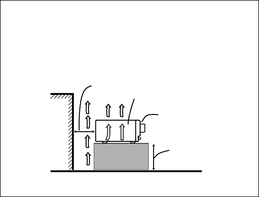
Caution: Proper Ventilation
To avoid risk of electric shock and fire and to protect from damage.
Locate the apparatus as follows:
Front: No obstructions open spacing.
Sides: No obstructions in 10 cm from the sides.
Top: No obstructions in 10 cm from the top.
Back: No obstructions in 15 cm from the back.
Bottom: No obstructions, place on the level surface.
In addition, maintain the best possible air circulation as illustrated.
Wall or obstructions
Front
Stand height 15 cm or more
RX-5032VSL
Spacing 15 cm or more
Floor
Safety_RX-5032V[A]f.P65 03.3.26, 17:462

1
Precautions
General precautions
• DO NOT insert any metal object into the unit.
• DO NOT disassemble the unit or remove screws, covers, or
cabinet.
• DO NOT expose the unit to rain or moisture.
Locations
• Install the unit in a location that is level and protected from
moisture.
• The temperature around the unit must be between –5˚C and
35˚C.
• Make sure there is good ventilation around the unit. Poor
ventilation could cause overheating and damage the unit.
Handling the unit
• DO NOT touch the power cord with wet hands.
• DO NOT pull on the power cord to unplug the cord. When
unplugging the cord, always grasp the plug so as not to
damage the cord.
• Keep the power cord away from the connecting cords and
the antenna. The power cord may cause noise or screen
interference. Coaxial cable is recommended for the antenna
connection, since such cable is well-shielded against
interference.
• When a power failure occurs, or when you unplug the power
cord, the preset settings such as preset FM or AM channels
and sound adjustments may be erased within a few days.
Before Installation
This mark indicates that ONLY the remote
control CAN be used for the operation
explained.
Remote
NOT
Checking the Supplied Accessories
Check to be sure you have all of the following supplied
accessories. The number in parentheses indicates the
quantity of each piece supplied.
• Remote control (1)
• Batteries (2)
• AM loop antenna (1)
• FM antenna (1)
If anything is missing, contact your dealer immediately.
This mark indicates that the remote control
CANNOT be used for the operation explained.
Use the buttons on the front panel.
01-09_RX-5032VSL[A]f.P65 03.3.26, 17:471

2
Table of Contents
Parts Identification ...................................... 3
Getting Started ........................................... 5
Connecting the AM and FM Antennas ............................. 5
Connecting the Speakers and Subwoofer ........................ 6
Connecting Audio/Video Components .............................. 7
Analog Connections ................................................................. 7
Digital Connections .................................................................. 9
Connecting the Power Cord ............................................. 9
Putting Batteries in the Remote Control ........................... 9
Basic Operations ....................................... 10
Turning On the Power ..................................................... 10
Selecting the Source to Play .......................................... 10
Changing the Source Name ........................................... 10
Selecting Different Sources for Picture and Sound ........ 11
Adjusting the Volume ...................................................... 11
Listening with Headphones Only .................................... 11
Turning Off the Sound Temporarily—Muting ................... 12
Changing the Display Brightness—DIMMER ................. 12
Turning Off the Power with the Sleep Timer ................... 12
Basic Settings ........................................... 13
Basic Settings Using MULTI JOG Dial ........................... 13
Setting the Speaker Information ............................................ 13
Selecting the Digital Input Terminals—DIGITAL IN ................ 14
Selecting the Analog or Digital Input Mode .................... 15
Sound Adjustments.................................... 16
Attenuating the Input Signal ........................................... 16
Turning Off the Subwoofer .............................................. 16
Sound Adjustments Using MULTI JOG Dial ................... 17
Sound Adjustments Using Remote Control .................... 18
Adjusting Speaker Output Levels Using Test Tone ................. 18
Adjusting Subwoofer Output Level ......................................... 19
Tuner Operations ....................................... 20
Tuning in to Stations Manually ........................................ 20
Using Preset Tuning ....................................................... 20
Storing the Preset Stations .................................................... 20
Tuning in to a Preset Station .................................................. 21
Selecting the FM Reception Mode ................................. 21
Creating Realistic Sound Fields ................... 22
Using Surround Modes ................................................... 24
Using DSP Modes .......................................................... 25
COMPU LINK Remote Control System ......... 26
AV COMPU LINK Remote Control System .... 27
Operating JVC’s Audio/Video
Components .......................................... 29
Operating Audio Components ........................................ 29
Operating Video Components ........................................ 31
Troubleshooting ......................................... 32
Specifications............................................ 33
01-09_RX-5032VSL[A]f.P65 03.3.26, 17:472
3
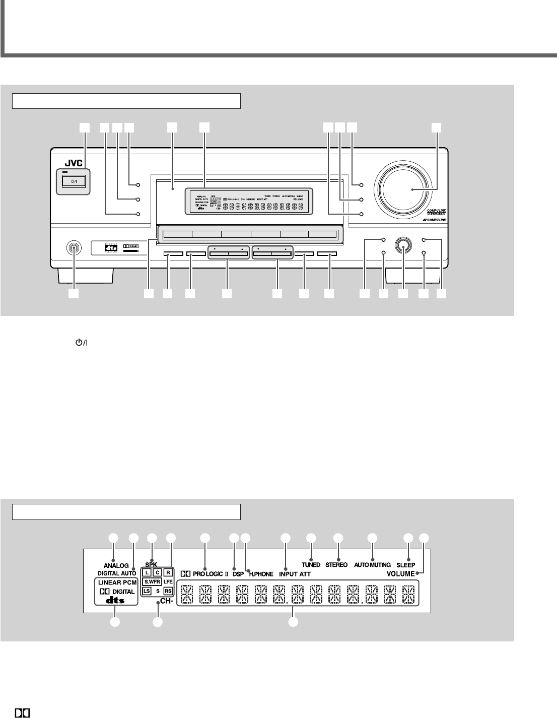
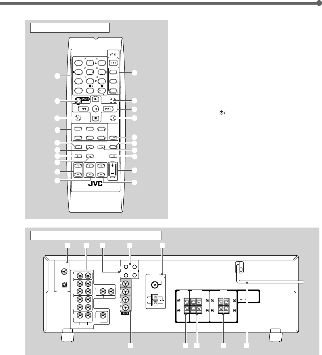
Parts Identification
See pages in parentheses for details.
1STANDBY/ON button and STANDBY lamp (10)
2SURROUND/DSP OFF button (24, 25)
3DSP button (25)
4SURROUND button (24)
5Remote sensor (9)
6Display (For details, see “Display” below.)
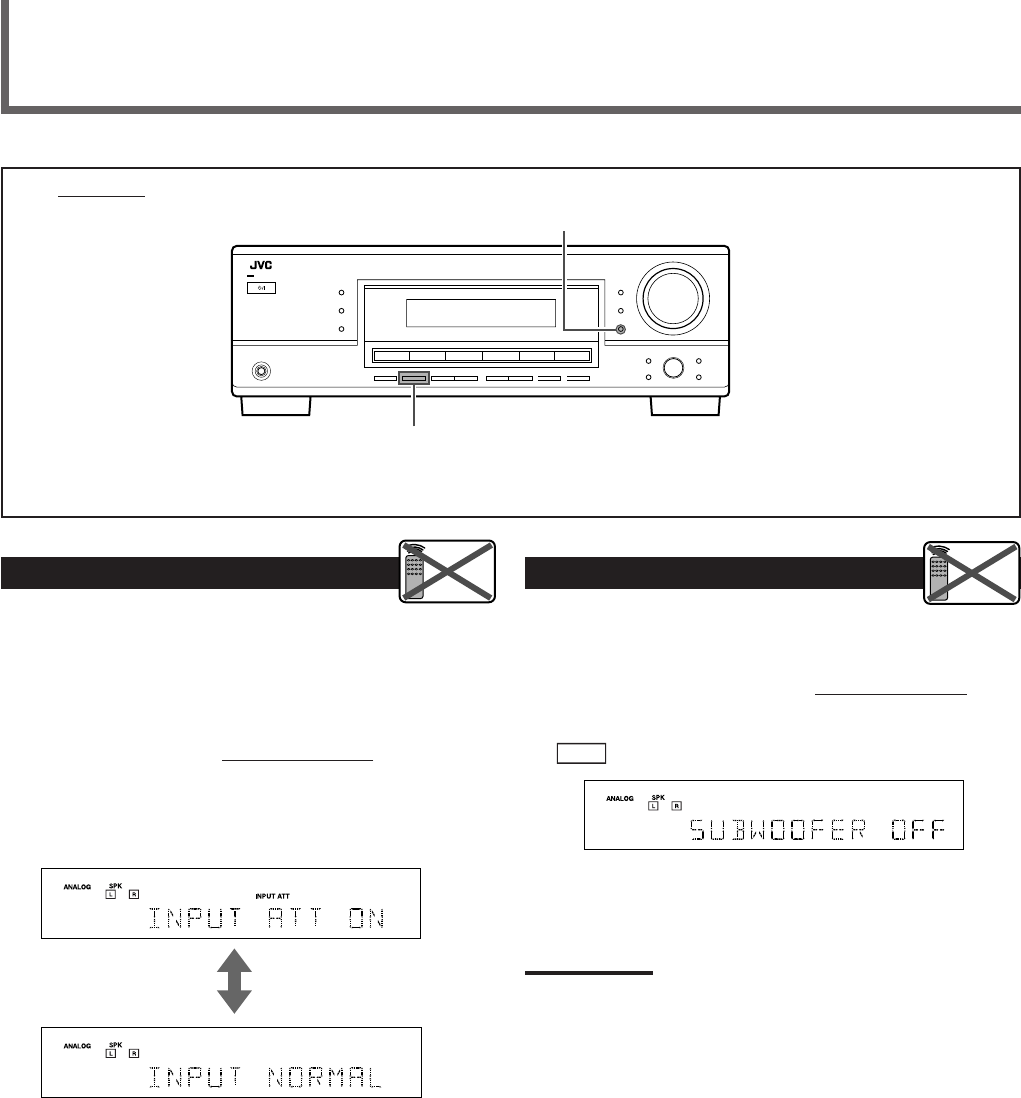
7• INPUT ANALOG button (15)
• INPUT ATT (attenuator) button (16)
8INPUT DIGITAL button (15)
9DIMMER button (12)
pMASTER VOLUME control (11)
qPHONES jack (11)
Front Panel
w• Source selection buttons (10)
DVD, VCR, TV SOUND, CD, TAPE/CDR, FM/AM
• SOURCE NAME button (10)
eSPEAKERS ON/OFF button (11)
rSUBWOOFER OUT ON/OFF button (16)
tFM/AM TUNING 5/∞ buttons (20)
yFM/AM PRESET 5/∞ buttons (20, 21)
uFM MODE button (21)
iMEMORY button (20)
oSETTING button (13)
;SET button (13, 17)
aMULTI JOG dial (13, 17)
sEXIT button (13, 17)
dADJUST button (17)
Display
See pages in parentheses for details.
1ANALOG indicator (15)
2DIGITAL AUTO indicator (15)
3SPK (speaker) indicator (11)
4Speaker indicators and signal indicators (25)
5 PRO LOGIC II indicator (22, 24)
6DSP indicator (23, 25)
7H.PHONE indicator (11)
8INPUT ATT (attenuator) indicator (16)
9TUNED indicator (20)
0STEREO indicator (20, 21)
-AUTO MUTING indicator (21)
=SLEEP indicator (12)
~VOLUME indicator (12)
!Digital signal format indicators (15)
@CH– indicator (20)
#Main display
STANDBY
STANDBY/ON
PHONES
SURROUND
DSP
SPEAKERS
ON/OFF
SUBWOOFER OUT FM MODE MEMORY
ON/OFF
FM/AM TUNING
SURROUND/DSP
OFF
DIMMER
MASTER VOLUME
INPUT DIGITAL
RX–5032V
AUDIO/VIDEO CONTROL RECEIVER
SETTING MULTI JOG
SET
ADJUST
EXIT
INPUT ANALOG
INPUT ATT
FM/AM PRESET
DIGITAL
PRO LOGIC
1234 5
qew rui o;asd
ty
DVD VCR CD FM/AM
TAPE/CDR
TV SOUND
6789 p
SOURCE NAME
1234 5 67 8 =-09
!
~
@#
01-09_RX-5032VSL[A]f.P65 03.3.26, 17:473
4
See pages in parentheses for details.
1•10 keys for selecting preset channels (21)
•10 keys for sound adjustment (18, 19)
•10 keys for operating audio/video components (29 – 31)
2SOUND button (18, 19)
3REC PAUSE button (30, 31)
4Source selection buttons (10)
TAPE/CDR, CD, DVD, FM/AM, TV SOUND, VCR
5FM MODE button (21)
6SURROUND button (24)
7DIMMER button (12)
8TV/VIDEO button (31)
9VCR CH (channel) +/– buttons (31)
0TV CH (channel) +/– buttons (31)
-STANDBY/ON buttons (10, 31)
AUDIO, TV, VCR, DVD
=SLEEP button (12)
~Operating buttons for audio/video components
3, 8, 7, ¢/4, FF/REW (30, 31)
!CD-DISC button (30)
@ANALOG/DIGITAL button (15)
#SURROUND/DSP OFF button (24, 25)
$DSP button (25)
%MUTING button (12)
^VOLUME +/– button (11)
&TV VOLUME +/– buttons (31)
Remote Control
Parts Identification
See pages in parentheses for details.
1DIGITAL IN terminals (9)
•Coaxial: DIGITAL 1 (DVD)
•Optical: DIGITAL 2 (CD)
2Audio input/output terminals (6 – 8)
•Input: CD IN, TAPE/CDR IN, VCR IN, TV SOUND IN,
DVD IN
•Output: TAPE/CDR OUT, VCR OUT
•SUBWOOFER OUT
3COMPU LINK-4 (SYNCHRO) terminals (26)
Rear Panel
4AV COMPU LINK terminals (27)
5FM/AM ANTENNA terminals (5)
6VIDEO (composite video) input/output terminals (8)
•Input: DVD IN, VCR IN
•Output: MONITOR OUT, VCR OUT
7CENTER SPEAKER terminals (6)
8SURROUND SPEAKERS terminals (6)
9FRONT SPEAKERS terminals (6)
pAC power cord (9)
AUDIO
TV
VCR
DVD
TEST
MENU
ENTER LEVEL
RETURN
SURROUND
/DSP
CD-DISC
SLEEP
REC PAUSE
FM MODE
SURROUND
DSP
DIMMER TV/VIDEO MUTING
OFF
VCR CH
TV CH
VOLUME
SURR RSURR L
SUBWFRCENTER
FRONT RFRONT L
100
1
4
7/P
10
2
5
8
0
3
6
9
10
REMOTE CONTROL RM- SRX
5032U
REW FF
TV VOLUME
STANDBY/ON
A/V CONTROL
RECEIVER
TAPE/CDR CD DVD
FM/AM TV SOUND VCR ANALOG
/DIGITAL
1
5
6
7
8
9
0
2
3
4
-
~
=
!
#
$
@
%
&
^
CAUTION :
SPEAKER IMPEDANCE
AM
LOOP
AM
EXT
CD
IN
OUT
(REC)
IN
(PLAY)
OUT
(REC)
VCR
TV SOUND
IN
SUBWOOFER
OUT
AV
COMPU LINK
COMPU LINK-4
(SYNCHRO)
ANTENNA
CENTER
SPEAKER
SURROUND
SPEAKERS
RIGHT LEFT
FRONT
SPEAKERS
RIGHT LEFT
AUDIO
RIGHT LEFT
RIGHT LEFT
IN
(PLAY)
TAPE
/CDR
DIGITAL 1
DIGITAL 2 ( CD )
DIGITAL IN
(DVD)
RIGHT
COAXIAL
FM 75
816
AUDIO
DVD
IN
MONITOR
OUT
DVD
IN
OUT
(REC)
VCR
IN
(PLAY)
897
12 435
6p
01-09_RX-5032VSL[A]f.P65 03.3.26, 17:474
5
AM
LOOP
FM 75
COAXIAL
AM
EXT
ANTENNA
FM 75
COAXIAL
FM 75
COAXIAL
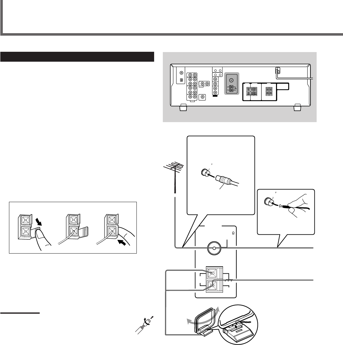
Connecting the AM and FM Antennas
AM antenna connection
Connect the supplied AM loop antenna to the AM LOOP
terminals.
Turn the loop until you have the best reception.
•If the reception is poor, connect an outdoor single vinyl-
covered wire (not supplied) to the AM EXT terminal. (Keep
the AM loop antenna connected.)
FM antenna connection
Connect the supplied FM antenna to the FM 75 Ω COAXIAL
terminal as a temporary measure.
Extend the supplied FM antenna horizontally.
•If the reception is poor, connect an outdoor FM antenna (not
supplied). Before attaching a 75 Ω coaxial cable with a
connector, disconnect the supplied FM antenna.
7How to connect the AM antenna cord
1
Open the terminal.
2
Insert the AM antenna cord.
3
Close the terminal.
Notes:
• If the AM loop antenna wire is covered with vinyl, remove
the vinyl by twisting it as shown to the right.
• Make sure the antenna conductors do not touch any other
terminals, connecting cords, or power cord. This could
cause poor reception.
Getting Started
Rear panel
AM loop antenna
(supplied)
If AM reception is poor, connect
outdoor single vinyl-covered wire
(not supplied).
Extend the supplied FM
antenna horizontally.
123
FM antenna (supplied)
•If FM reception is poor,
connect an outdoor FM
antenna.
Snap the tabs on the
loop into the slots of
the base to assemble
the AM loop antenna.
75 Ω coaxial cable with a
connector (not supplied)
01-09_RX-5032VSL[A]f.P65 03.3.26, 17:475
6
Getting Started
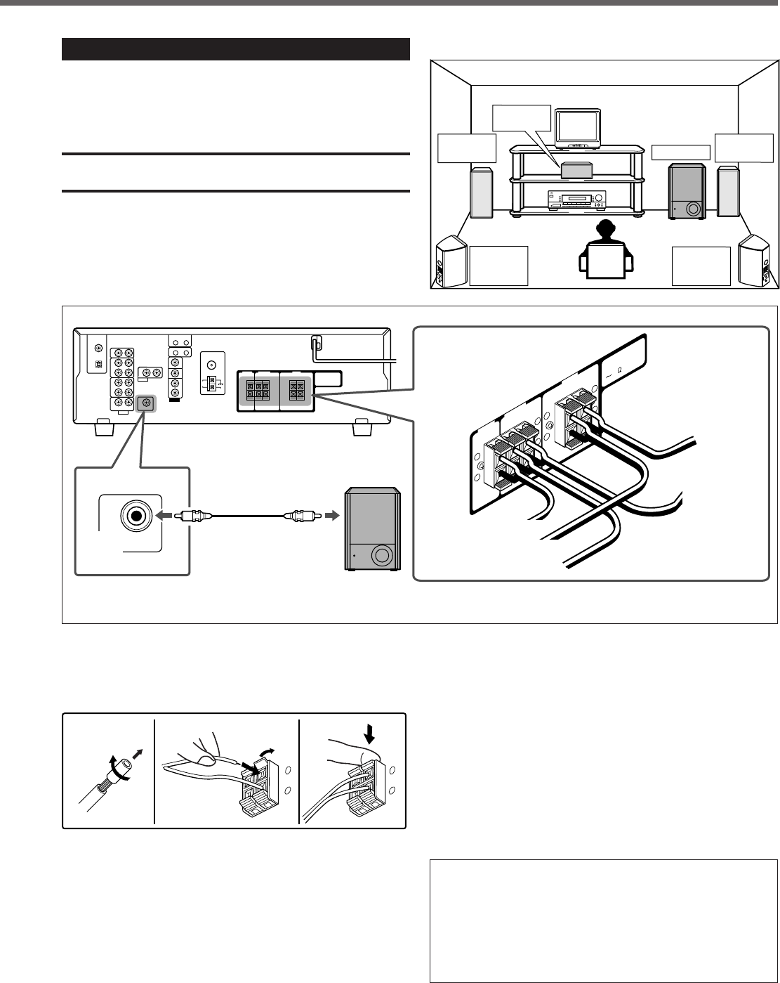
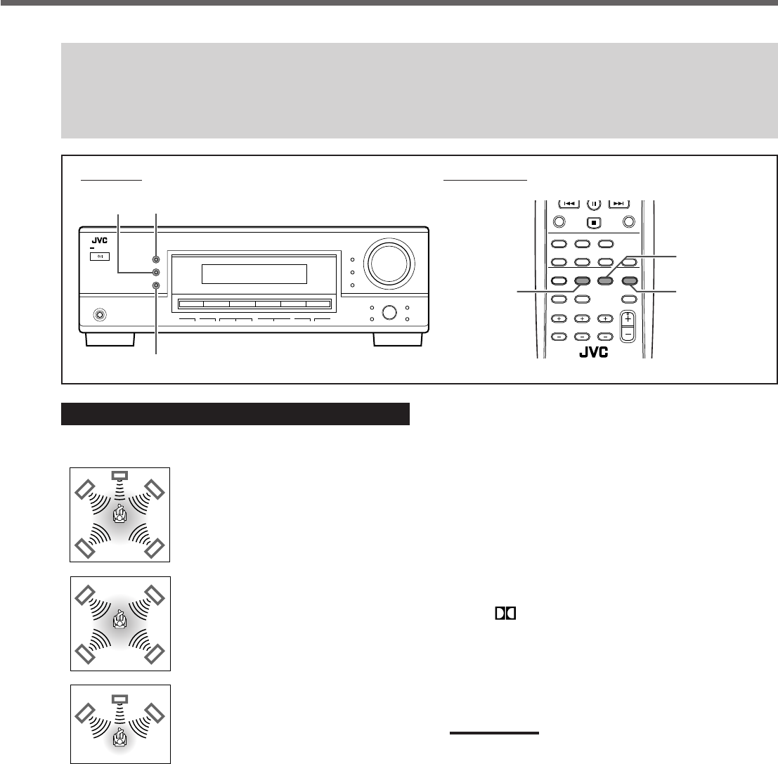
7Speaker layout diagram
Connecting the Speakers and Subwoofer
You can connect five speakers—a pair of front speakers, a
center speaker, and a pair of surround speakers—and a
subwoofer.
CAUTION:
Use speakers with a SPEAKER IMPEDANCE as indicated by the
speaker terminals.
7Connection diagram
7How to connect speaker cords
For each speaker, connect the (+) and (–) terminals on the
rear panel to the (+) and (–) terminals marked on the
speakers.
1
Twist and remove the insulation at the end of
each speaker cord.
2
Open the terminal (1), then insert the speaker
cord (2).
3
Close the terminal.
1
2
12 3
+
–
+
–
Powered
subwoofer
To subwoofer
input
7How to connect the subwoofer
Connect the input jack of a powered subwoofer to the
SUBWOOFER OUT jack on the rear panel, using a cable with
RCA pin plugs (not supplied).
• Refer also to the manual supplied with your subwoofer.
By connecting a subwoofer, you can enhance the bass or
reproduce the original LFE signals recorded in the digital
software.
Since bass sound is non-directional, you can place a
subwoofer wherever you like. Normally place it in front of
you.
After connecting the front, center, surround speakers and/
or a subwoofer, set the speaker setting information properly
to obtain the best possible Surround effects with your
listening conditions. For details, see pages 13 and 14.
•“NO” for the subwoofer and “LARGE” for the front
speakers, “SMALL” for the center and surround speakers
are initial settings.
Cable with RCA pin
plugs (not supplied)
Left front
speaker Subwoofer
Center
speaker
Left
surround
speaker
Right
surround
speaker
Right front
speaker
CENTER
SPEAKER
SURROUND
SPEAKERS
RIGHT LEFT
FRONT
SPEAKERS
RIGHT LEFT
CAUTION :
SPEAKER IMPEDANCE
816
+
–
+
–
+
–
+
–
To left
front speaker
To right surround speaker
To center speaker
To right front speaker
To left surround
speaker
SUBWOOFER
OUT
01-09_RX-5032VSL[A]f.P65 03.3.26, 17:476
7
CD
IN
OUT
(REC)
IN
(PLAY)
OUT
(REC)
VCR
TV SOUND
IN
AUDIO
RIGHT LEFT
IN
(PLAY)
TAPE
/CDR
R
R
L
R
L
L
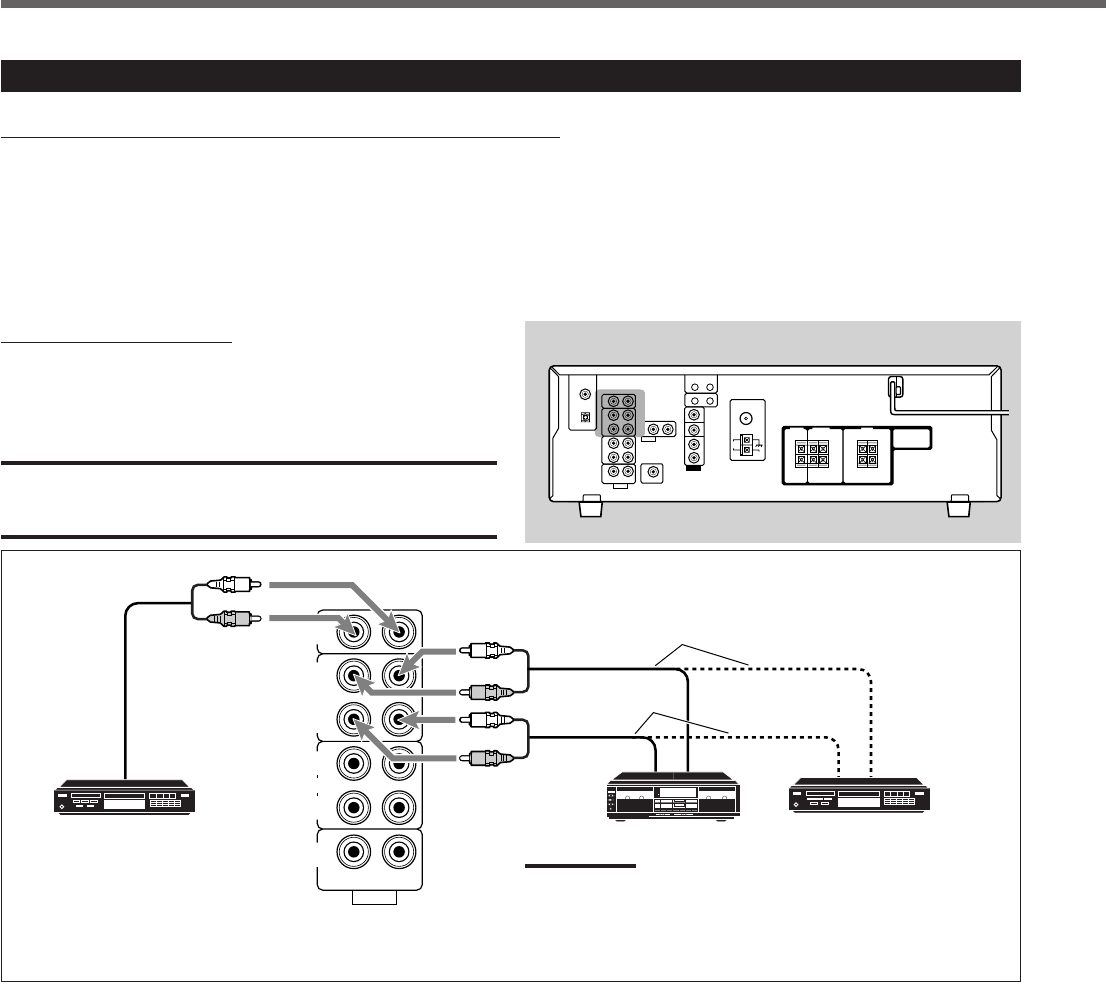
Connecting Audio/Video Components
Turn the power off to all components before making connections.
You can connect the following audio/video components to this receiver. Refer also to the manuals supplied with your
components.
•Audio Components: CD player* and Cassette deck (or CD recorder*)
•Video Components: VCR, TV*, and DVD player*
*
You can connect these components using the methods described in “Analog Connections” (below) and/or in “Digital Connections” (see page 9).
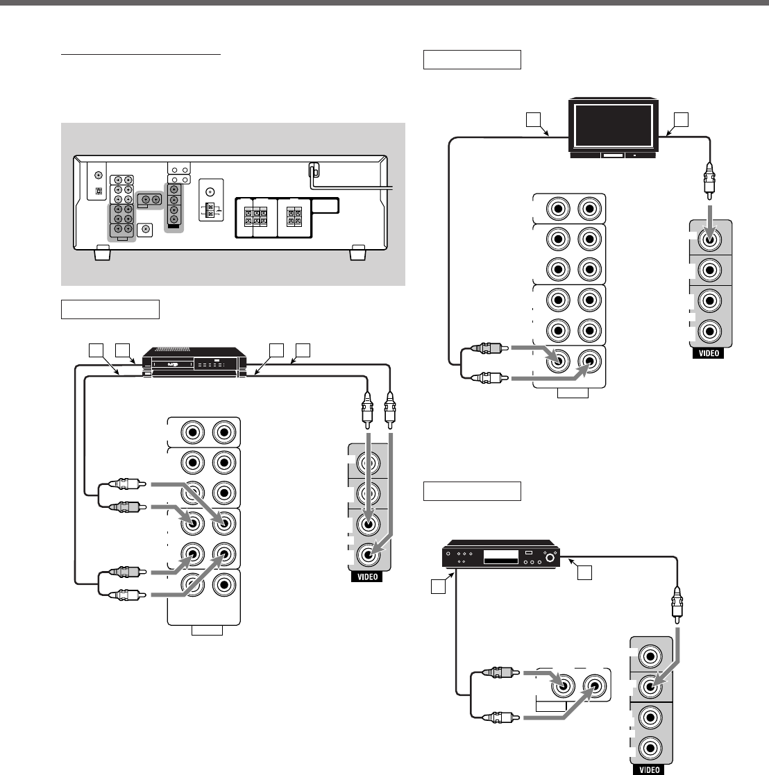
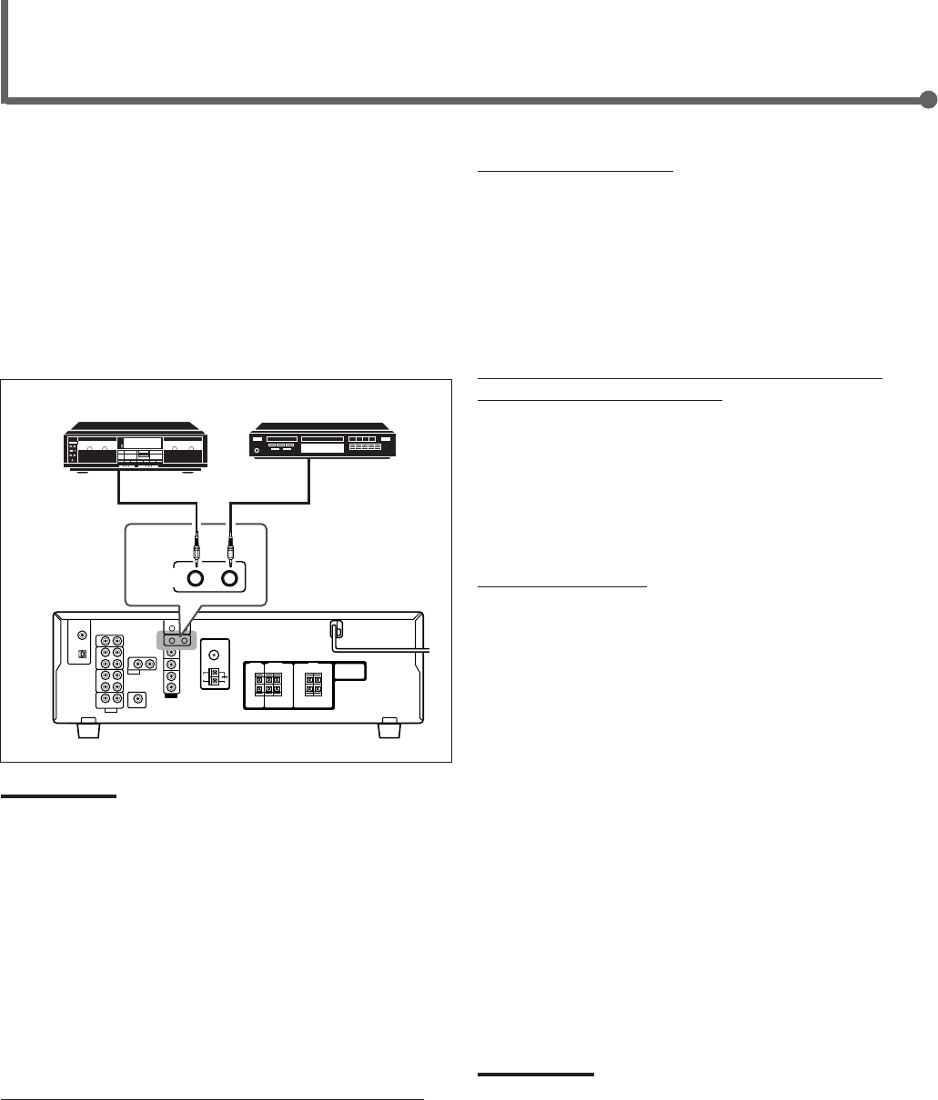
Analog Connections
Audio component connections
Use cables with RCA pin plugs (not supplied).
Connect the white plug to the audio left jack and the red plug
to the audio right jack.
CAUTION:
If you connect a sound-enhancing device such as a graphic equalizer
between the source components and this receiver, the sound output
through this receiver may be distorted.
Rear panel
CD recorder
Cassette deck
CD player
Note:
You can connect either a cassette deck or a CD recorder to the
TAPE/CDR jacks. When connecting a CD recorder to the TAPE/
CDR jacks, change the source name to CDR so that “CDR”
appears on the display when selected as the source. See page 10
for details.
If your audio components have a COMPU LINK jack
See also page 26 for detailed information about the connections with the COMPU LINK remote control system.
To audio input
To audio output
To audio output
Getting Started
01-09_RX-5032VSL[A]f.P65 03.3.26, 17:477
8
ÅTo left/right audio input
ıTo left/right audio output
ÇTo video input
ÎTo video output
Getting Started
Rear panel
VCR
TV
ÅTo audio output
ıTo video input
VCR
TV
Video component connections
Use cables with RCA pin plugs (not supplied).
Connect the white plug to the audio left jack, the red plug to
the audio right jack, and the yellow plug to the video jack.
CD
IN
OUT
(REC)
IN
(PLAY)
OUT
(REC)
VCR
TV SOUND
IN
AUDIO
RIGHT LEFT
IN
(PLAY)
TAPE
/CDR
MONITOR
OUT
DVD
IN
OUT
(REC)
IN
(PLAY)
VCR
A B
R
L
DVD
ÅTo audio output
ıTo video output
To use software encoded with Dolby Digital or DTS
Digital Surround, connect the DVD player using one of
the DIGITAL IN terminals (see page 9).
DVD player
RIGHT LEFT
AUDIO
DVD
IN
MONITOR
OUT
DVD
IN
OUT
(REC)
VCR
IN
(PLAY)
DVD
B
A
R
L
CD
IN
OUT
(REC)
IN
(PLAY)
OUT
(REC)
VCR
TV SOUND
IN
AUDIO
RIGHT LEFT
IN
(PLAY)
TAPE
/CDR
MONITOR
OUT
DVD
IN
OUT
(REC)
IN
(PLAY)
VCR
R
R
L
L
A B C D
01-09_RX-5032VSL[A]f.P65 03.3.26, 17:478
9
DIGITAL 1
DIGITAL 2 ( CD )
DIGITAL IN
(DVD)
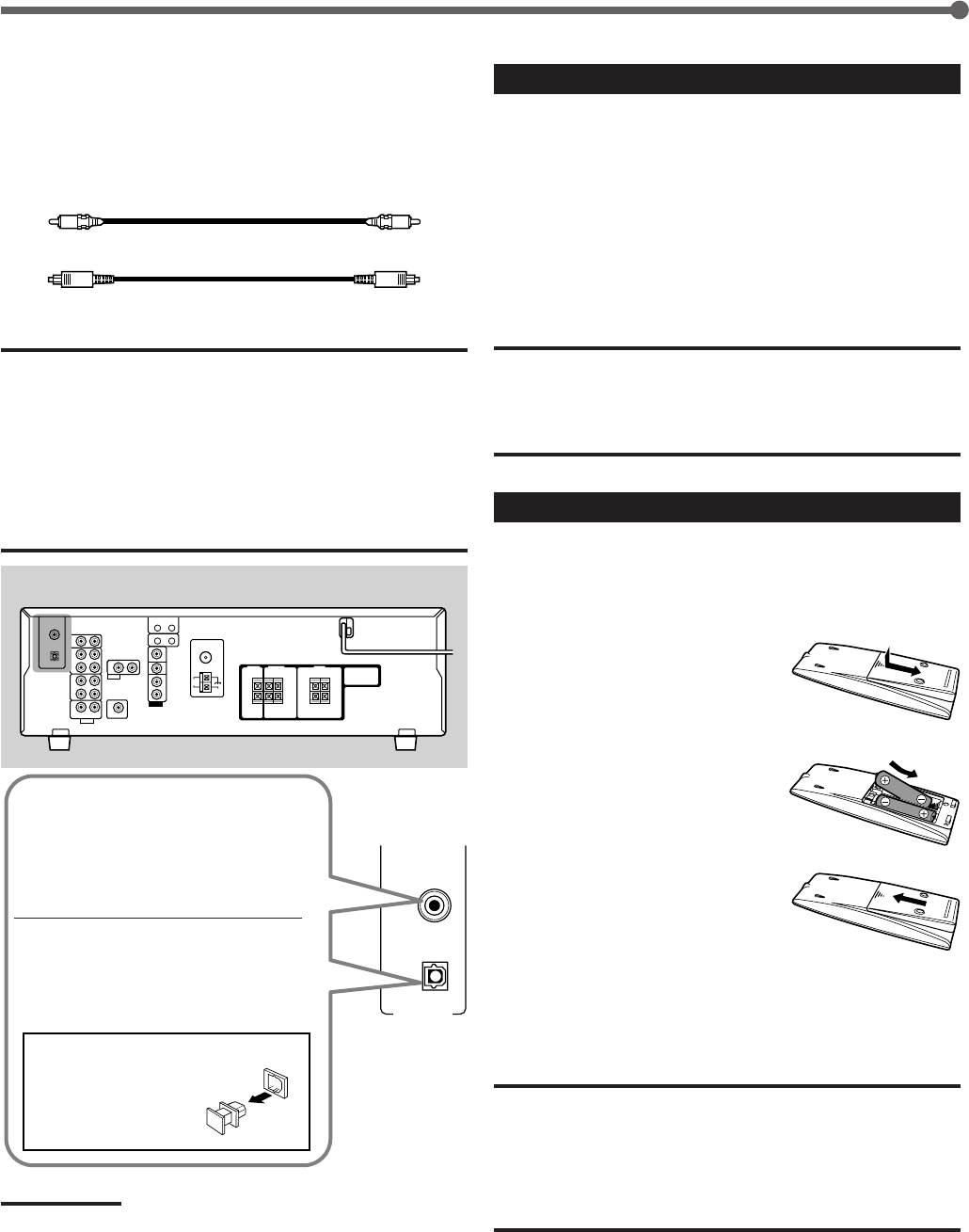
Digital Connections
This receiver is equipped with two DIGITAL IN terminals—one
digital coaxial terminal and one digital optical terminal.
You can connect any component to one of the digital terminals
using a digital coaxial cable (not supplied) or digital optical
cable (not supplied).
Digital coaxial cable
Digital optical cable
IMPORTANT:
•When connecting a video component using the digital terminal, you
also need to connect it to the video jack on the rear. Without
connecting it to the video jack, you cannot view the playback picture.
•After connecting the components using the DIGITAL IN terminals,
correctly set the following if necessary:
–Set the digital input (DIGITAL IN) terminal setting correctly. For
details, see “Selecting the Digital Input Terminals—DIGITAL IN” on
page 14.
–Select the digital input mode correctly. For details, see “Selecting
the Analog or Digital Input Mode” on page 15.
Rear panel
When the component has a digital
coaxial output terminal, connect it to
the DIGITAL 1 (DVD) terminal, using
the digital coaxial cable (not
supplied).
When the component has a digital
optical output terminal, connect it to
the DIGITAL 2 (CD) terminal, using
the digital optical cable (not
supplied).
Before connecting a digital
optical cable, unplug the
protective plug.
Notes:
•When shipped from the factory, the DIGITAL IN terminals have been
set for use with the following components:
–DIGITAL 1 (coaxial): For DVD player
–DIGITAL 2 (optical): For CD player
•When you want to operate the CD player or CD recorder using the
COMPU LINK remote control system, connect the target component
also as described in “Analog Connections” (see page 7).
•When you want to operate the DVD player using the AV COMPU
LINK remote control system, connect the DVD player also as
described in “Analog connections” (see page 8).
Getting Started
Connecting the Power Cord
Before plugging the power cord into an AC outlet, make sure
that all connections have been made.
Plug the power cord into an AC outlet.
Keep the power cord away from the connecting cables and the
antenna. The power cord may cause noise or screen
interference. We recommend that you use a coaxial cable to
connect the antenna, since it is well-shielded against
interference.
CAUTIONS:
•Do not plug in before setting the voltage selector switch on the rear
of the unit and all connection procedures are complete.
•Do not touch the power cord with wet hands.
•Do not pull on the power cord to unplug the cord. When unplugging
the cord, always grasp the plug so as not to damage the cord.
Putting Batteries in the Remote Control
Before using the remote control, put two supplied batteries
first.
•When using the remote control, aim the remote control
directly at the remote sensor on the front panel.
1
On the back of the remote
control, remove the
battery cover.
2
Insert batteries.
•Make sure to match the polarity:
(+) to (+) and (–) to (–).
3
Replace the cover.
If the range or effectiveness of the remote control decreases,
replace the batteries. Use two R6P(SUM-3)/AA(15F) type dry-
cell batteries.
CAUTION:
Follow these precautions to avoid leaking or cracking cells:
•Place batteries in the remote control so they match the polarity:
(+) to (+) and (–) to (–).
•Use the correct type of batteries. Batteries that look similar may
differ in voltage.
•Always replace both batteries at the same time.
•Do not expose batteries to heat or flame.
01-09_RX-5032VSL[A]f.P65 03.3.26, 17:479
10
Notes:
• When connecting a CD recorder to the TAPE/CDR jacks, change the
source name to CDR so that “CDR” appears on the display when
selected as the source. See “Changing the Source Name” below.
• When you have connected some digital source components using
the digital terminals (see page 9), you need to select the digital input
terminals (see page 14).
• When you press one of the source selection buttons on the remote
control marked with an asterisk (
*
), the receiver automatically turns
on.
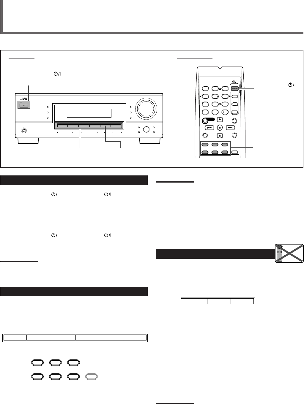
Turning On the Power
Press STANDBY/ON (or STANDBY/ON AUDIO on the
remote control).
The STANDBY lamp goes off. The name of the current source
(or station frequency) appears on the display.
To turn off the power (into standby mode)
Press STANDBY/ON (or STANDBY/ON AUDIO on the
remote control) again.
The STANDBY lamp lights up.
Note:
A small amount of power is consumed in standby mode. To turn the
power off completely, unplug the AC power cord.
Selecting the Source to Play
Press one of the source selection buttons.
The selected source name appears on the display.
On the front panel
From the remote control
DVD: Select the DVD player.
VCR: Select the VCR.
TV SOUND: Select the TV sound.
CD*: Select the CD player.
TAPE/CDR*: Select the cassette deck (or the CD recorder).
FM/AM*: Select an FM or AM broadcast.
• Each time you press the button, the band
alternates between FM and AM.
Basic Operations
STANDBY/ON
AUDIO
Source selection
buttons
Front panel Remote control
Source selection
buttons
STANDBY/ON
and STANDBY lamp
SOURCE NAME
FM/AMTAPE/CDR
CD
TV SOUNDVCR
DVD
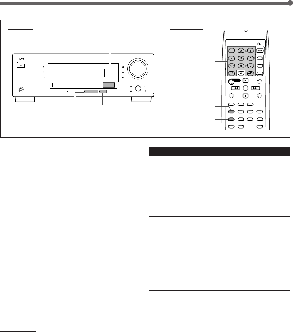
Changing the Source Name
When you have connected a CD recorder to the TAPE/CDR
jacks on the rear panel, change the source name to CDR so
that “CDR” appears on the display when selected as the
source.
1
Press TAPE/CDR (SOURCE NAME) on the
front panel.
• Make sure “TAPE” appears on the display.
2
Press again and hold SOURCE NAME
(TAPE/CDR) on the front panel until
“ASSIGN CDR” appears on the display.
To change the source name from “CDR” to “TAPE,” repeat
the same procedure above (in step
1
, make sure “CDR”
appears on the display).
Note:
Without changing the source name, you can still use the connected
components; however, you may experience one of the following
inconveniences:
• A different source name will appear on the display when you select
the target component.
• You cannot use the digital input (see page 14) for the CD recorder.
• You cannot use the COMPU LINK remote control system (see page
26) to operate the target component.
Remote
NOT
SOURCE NAME
TAPE/CDR
CD FM/AM
RX–5032V
AUDIO/VIDEO CONTROL RECEIVER
1
4
7/P
10
2
5
8
0
3
6
9
10
TA/NEWS/INFO
DISPLAY MODE
A/V CONTROL
RECEIVER
SOURCE NAME
TAPE/CDR CD DVD
FM/AM TV SOUND VCR ANALOG
/DIGITAL
10-15_RX-5032VSL[A]f.P65 03.3.26, 17:4510
11
Selecting Different Sources for Picture
and Sound
You can watch the picture from a video component while
listening to sound from another component.
Press one of the audio source selection buttons while
watching the picture from a video component such as the
VCR or DVD player.
•Once you have selected a video source, pictures of the
selected source are sent to the TV until you select another
video source.
On the front panel From the remote control
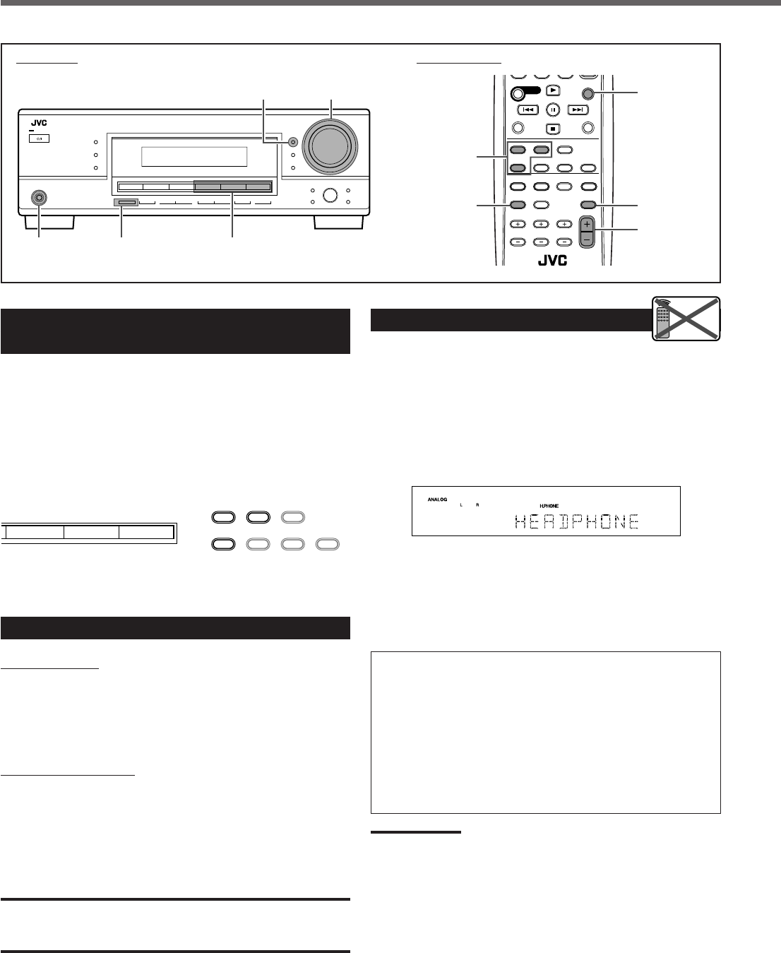
Adjusting the Volume
On the front panel
To increase the volume, turn MASTER VOLUME control
clockwise.
To decrease the volume, turn MASTER VOLUME control
counterclockwise.
From the remote control
To increase the volume, press VOLUME +.
To decrease the volume, press VOLUME –.
The volume level can be adjusted within a range of
“0” (minimum) to “50” (maximum).
CAUTION:
Always set the volume to the minimum before starting any source. If
the volume is set at a high level, the sudden blast of sound energy
can permanently damage your hearing and/or ruin your speakers.
SOURCE NAME
FM/AMTAPE/CDRCD
TAPE/CDR CD DVD
FM/AM TV SOUND VCR ANALOG
/DIGITAL
Listening with Headphones Only
You must turn off the speakers when you listen with
headphones.
1
Press SPEAKERS ON/OFF on the front
panel.
“HEADPHONE” appears on the display for a while.
The SPK indicator goes off and the H.PHONE indicator
lights up.
This cancels the Surround/DSP modes currently selected
and activates the HEADPHONE mode (see below).
2
Connect a pair of headphones to the
PHONES jack on the front panel
.
HEADPHONE mode
When using the headphones, the following signals are sent
to the headphones regardless of your speaker setting:
–For 2 channel sources, the front left and right channel
signals are sent directly to the headphones.
–For multi-channel sources, the front left/right, center, and
surround left/right channel signals are down-mixed and
then sent to the headphones.
You can enjoy multi-channel sound sources using the
headphones.
Note:
While in the HEADPHONE mode, you cannot use any Surround/DSP
modes (see pages 22 to 25).
Remote
NOT
Basic Operations
MUTING
VOLUME +/–
Front panel Remote control
DIMMER
DIMMER SLEEP
Audio source
selection buttons
Audio source
selection buttons
SPEAKERS
ON/OFF
PHONES jack
MASTER VOLUME
control
RX–5032V
AUDIO/VIDEO CONTROL RECEIVER
10 0 10
TA/NEWS/INFO
DISPLAY MODE
10-15_RX-5032VSL[A]f.P65 03.3.26, 17:4511
12
Changing the Display Brightness—
DIMMER
You can dim the display.
Press DIMMER.
•Each time you press the button, the display dims and
brightens alternately.
Turning Off the Power
with the Sleep Timer
You can fall asleep while listening to music—Sleep Timer.
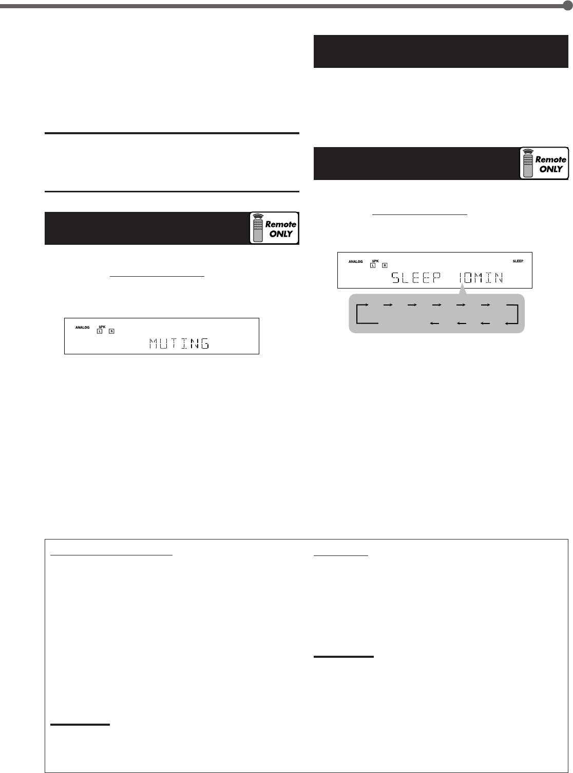
Press SLEEP on the remote control repeatedly.
•The SLEEP indicator lights up on the display.
Each time you press the button, the shut-off time changes in
10 minute intervals as follows:
When the shut-off time comes, the receiver turns off
automatically.
To check or change the shut-off time, press SLEEP once.
The remaining time (in minutes) until the shut-off time
appears.
•To change the shut-off time, press SLEEP repeatedly.
To cancel the Sleep Timer, press SLEEP repeatedly until
“SLEEP 0MIN” appears on the display. (The SLEEP indicator
goes off.)
•Turning off the power also cancels the Sleep Timer.
After using the headphones
1
Press SPEAKERS ON/OFF on the front panel to
activate the speakers.
The H.PHONE indicator goes off and the SPK indicator
lights up.
2
Disconnect the headphones.
CAUTION:
Be sure to turn down the volume
•Before connecting or putting on headphones, as high volume can
damage both the headphones and your hearing.
•Before turning on speakers again, as high volume may be output
from the speakers.
Turning Off the Sound
Temporarily—Muting
You can turn off the volume temporarily.
Press MUTING on the remote control to mute the sound
through all speakers or headphones.
•“MUTING” appears on the display and the volume turns off
(the VOLUME indicator goes off).
To restore the sound, press MUTING again.
The VOLUME indicator lights up on the display.
•Turning MASTER VOLUME control on the front panel or
pressing VOLUME +/– on the remote control also restores
the sound.
Basic adjustment auto memory
This receiver memorizes sound settings for each source
when—:
•you turn off the power,
•you change the source, and
•you assign the source name.
When you change the source, the memorized settings for
the newly selected source are automatically recalled.
The following can be stored for each source:
•Input attenuator mode (see page 16)
•Tone adjustment (see page 18)
•Speaker output level (see pages 18 and 19)
•Surround/DSP mode selection (see pages 24 and 25)
Notes:
• You cannot assign and store different settings for digital input
mode and analog input mode.
• If the source is FM or AM, you can assign a different setting for
each band.
For recording
You can record any sources playing through the receiver to a
cassette deck (or a CD recorder) connected to the
TAPE/CDR jacks and the VCR connected to the VCR jacks
at the same time.
While recording, you can listen to the selected sound source
at whatever sound level you like without affecting the sound
levels of the recording.
Note:
The output volume level, tone adjustment (see page 18), and
Surround/DSP modes (see pages 24 and 25) do not affect the
recording.
Basic Operations
2010 30 40 50 60
70
8090
(Canceled)
0
10-15_RX-5032VSL[A]f.P65 03.3.26, 17:4512
13
4
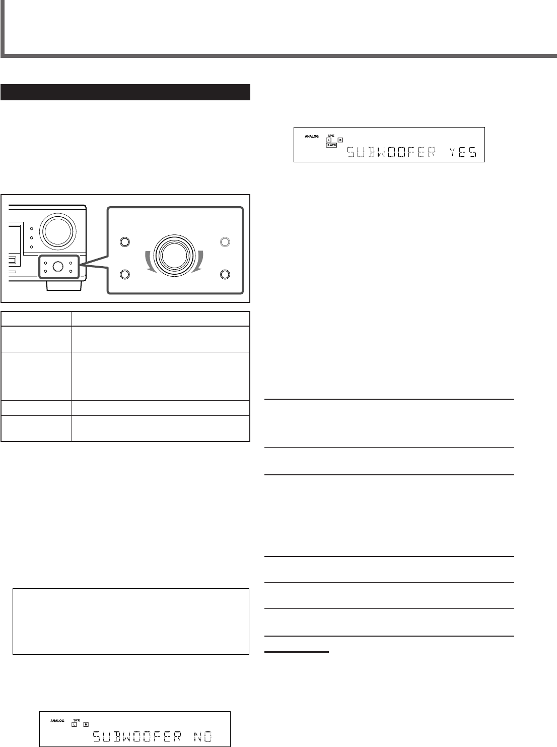
Turn MULTI JOG dial to adjust the selected
item.
Select “SUBWOOFER YES” if a subwoofer is connected.
Ex.: When “SUBWOOFER YES” is selected.
5
Press EXIT.
To adjust other items, repeat steps
2
to
5
.
To finish the setting, go to step
6
.
6
Press EXIT again.
The receiver exits from the basic setting mode.
Setting the Speaker Information
“NO” for the subwoofer, “LARGE” for the front speakers, and
“SMALL” for the center and surround speakers are initial
settings.
To get best possible sound, change the subwoofer and
speaker settings to fit your listening conditions.
7 Subwoofer information—SUBWOOFER
Register whether you have connected a subwoofer or not.
YES Select this when you have connected a
subwoofer.
You can adjust the subwoofer output level
(see page 19).
NO Select this when you have not connected or have
disconnected a subwoofer.
7Speaker size—FRNT (Front) SPEAKERS, CNTR (Center)
SPEAKER, SURR (Surround) SPEAKERS
Register the sizes of all the connected speakers.
•When you change your speakers, register the information
about the speakers again.
LARGE Select this when the size of the cone speaker unit
built in your speaker is greater than 12 cm.
SMALL Select this when the size of the cone speaker unit
built in your speaker is smaller than 12 cm.
NONE Select this when you have not connected a
speaker. (Not selectable for the front speakers.)
Notes:
• If you have selected “NO” for the subwoofer setting, you can only
select “LARGE” for the front speaker setting.
• If you have selected “SMALL” for the front speaker setting, you
cannot select “LARGE” for the center and surround speaker settings.
Basic Settings Using MULTI JOG Dial
After connecting and placing speakers, you need to make
basic settings for the following items according to your
listening conditions.
•Speaker information (see the right column and page 14)
•Digital input terminal sources (see page 14)
7Operating buttons
Buttons To do
SETTING Enter the receiver into the basic setting
mode.
MULTI JOG •Select an item to adjust after pressing
SETTING.
•Adjust the selected item after pressing
SET.
SET Determine the item to adjust.
EXIT Exit from the basic setting mode or return
to the previous step.
7Operating procedure
Ex. Setting the subwoofer information
Before you start, remember...
There is a time limit in doing the following steps. If the setting
is canceled before you finish, start again from step
1
.
1
Press SETTING.
The last selected item appears on the display.
2
Turn MULTI JOG dial to select an item you
want to adjust.
3
Press SET.
The current setting of the selected item appears on the
display.
Ex.: When “SUBWOOFER” is selected.
Basic Settings
SUBWOOFER FRNT SPEAKERS CNTR SPEAKER
SURR SPEAKERS DISTANCE UNIT FRNT DISTANCE
CNTR DISTANCE SURR DISTANCE CROSSOVER
LFE ATTENUATE D_COMPRESSION DIGITAL IN
(back to the beginning)
OO
OOO
O
OO O
O
OO
SETTING MULTI JOG
SET
ADJUST
EXIT
10-15_RX-5032VSL[A]f.P65 03.3.26, 17:4513
14
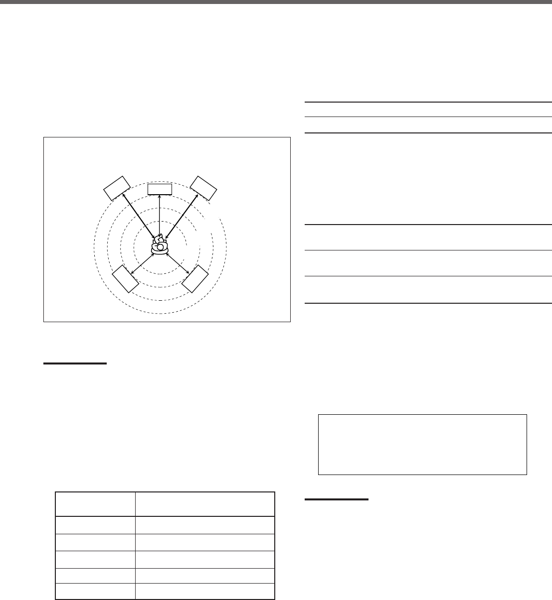
7Speaker distance—DISTANCE UNIT,
FRNT (Front) DISTANCE, CNTR (Center) DISTANCE,
SURR (Surround) DISTANCE
Select the unit to measure the distance between your listening
position and speakers—“METER” or “FEET.”
After selecting the measuring unit, select the appropriate
speaker distance for each speaker within the range of “0.3m”
(“1FT”) to “9.0m” (“30FT”) by 0.3 m (1 foot) step.
Example:In this case, set “FRNT DISTANCE” to “3.0m” (“10FT”),
“CNTR DISTANCE” to “2.7m” (“9FT”), and “SURR
DISTANCE” to “2.4m” (“8FT”).
•“METER” for the unit and “3.0m” (“10FT”) for all speakers are
the initial settings.
Note:
If you have selected “NONE” for the center and surround speakers
setting, you cannot set the speaker distance for the center and
surround speakers.
7Crossover frequency—CROSSOVER
Small speakers cannot reproduce the bass sounds efficiently.
If you use a small speaker in any position, this receiver
automatically reallocates the bass sound elements assigned
to the small speaker to other large speakers.
To use this function properly, set the crossover frequency
according to the table below:
•If you have selected “LARGE” for all speakers, this function
will not take effect (“CROSS OFF” appears).
3.0 m
(10 feet)
L
RS
C
2.7 m
(9 feet)
2.4 m
(8 feet)
2.1 m
(7 feet)
R
LS
(back to the beginning)
1 DVD 2 CD 1 DVD 2 TV 1 DVD 2 CDR
1 CD 2 CDR
1 TV 2 DVD 1 TV 2 CD
1 CD 2 DVD 1 CD 2 TV
1 TV 2 CDR
1 CDR 2 DVD 1 CDR 2 CD 1 CDR 2 TV
O
O
O
O
O
O
O
O
O
O
O
O
7Low Frequency Effect attenuator—LFE ATTENUATE
If the bass sound is distorted while playing back software
encoded with Dolby Digital or DTS Digital Surround, select
“–10dB” to activate the Low Frequency Effect attenuator.
•This function takes effect only when the LFE signals come
in.
0dB Normally select this (initial setting).
–10dB Select this when the bass sound is distorted.
7Dynamic range compression—D_COMPRESSION
You can compress the dynamic range (difference between
maximum sound and minimum sound) of the reproduced
sound. This is useful when using surround sound at night.
•This function takes effect only when playing back a source
using Dolby Digital.
MID Select this when you want to reduce the dynamic
range a little (initial setting).
MAX Select this when you want to apply the
compression effect fully. (Useful at night.)
OFF Select this when you want to enjoy surround sound
with its full dynamic range. (No effect applied.)
Selecting the Digital Input Terminals—
DIGITAL IN
When you use the digital input terminals, register which
components are connected to which terminals (DIGITAL 1/2)
so that the correct source name will appear when you select
the digital source.
Select the appropriate option from the following:
Note:
When shipped from the factory, the DIGITAL IN terminals have been
set for use with the following components:
• DIGITAL 1 (coaxial): For DVD player
• DIGITAL 2 (optical): For CD player
Crossover frequency
80HZ
100HZ
120HZ
150HZ
200HZ
Size of cone speaker unit built in the
small speaker
about 12 cm
about 10 cm (initial setting)
about 8 cm
about 6 cm
less than 5 cm
Basic Settings
10-15_RX-5032VSL[A]f.P65 03.3.26, 17:4514
15
If the following symptoms occur while playing Dolby Digital or
DTS encoded software with “DIGITAL AUTO” selected,
change the digital input mode.
•Sound does not come out at the beginning of playback.
•Noise comes out while searching or skipping chapters or
tracks.
Press INPUT DIGITAL on the front panel
repeatedly to select “DOLBY DIGITAL” or “DTS
SURROUND.”
•Each time you press the button, the digital input mode
changes as follows:
•To play back software encoded with Dolby Digital, select
“DOLBY DIGITAL.”
•To play back software encoded with DTS Digital Surround,
select “DTS SURROUND.”
Note:
When you turn off the power or select another source, “DOLBY
DIGITAL” or “DTS SURROUND” is canceled and the digital input mode
is automatically reset to “DIGITAL AUTO.”
The ANALOG indicator and digital signal format indicators on
the display indicate what type of signal comes into the
receiver.
ANALOG Lights when the analog input is selected.
LINEAR PCM Lights when Linear PCM signals come in.
DIGITAL •Lights when Dolby Digital signals come in.
•Flashes when “DOLBY DIGITAL” is selected
for software not encoded with Dolby Digital
signals.
•Lights when DTS signals come in.
•Flashes when “DTS SURROUND” is
selected for software not encoded with DTS
signals.
Note:
When “DIGITAL AUTO” cannot recognize the incoming signals, no
digital signal format indicators light up on the display.
Selecting the Analog or Digital Input
Mode
When you have connected digital source components using
both the analog connection (see pages 7 and 8) and the
digital connection (see page 9) methods, you need to select
the input mode correctly.
1
Press one of the source selection buttons—
DVD, TV SOUND, CD, or TAPE/CDR*—for
which you want to change the input mode.
Note:
*
Among the sources listed above, you can select the digital input
only for the sources for which you have selected the digital input
terminals. (See “Selecting the Digital Input Terminals—DIGITAL
IN” on page 14.)
2
Select digital input mode.
On the front panel
Press INPUT DIGITAL.
“DIGITAL AUTO” appears on the display.
The DIGITAL AUTO indicator also lights up.
To change the input mode back to analog input, press
INPUT ANALOG.
“ANALOG” appears on the display for a while.
The ANALOG indicator lights up.
From the remote control
Press ANALOG/DIGITAL.
•Each time you press the button, the input mode
alternates between the analog input (“ANALOG”) and
the digital input (“DIGITAL AUTO”).
DIGITAL AUTO Select this for the digital input mode.
The receiver automatically detects the
incoming signal format.
ANALOG Select this for the analog input mode
(initial setting).
Front panel Remote control
Source selection
buttons
INPUT DIGITAL
INPUT ANALOG
Source selection
buttons
ANALOG/DIGITAL
DIGITAL AUTO DOLBY DIGITAL
DTS SURROUND
Remote
NOT
Basic Settings
DIGITAL
PRO LOGIC
DIGITAL
SURROUND
RX–5032V
AUDIO/VIDEO CONTROL RECEIVER
DISPLAY MODE
10-15_RX-5032VSL[A]f.P65 03.3.26, 17:4515
16
Turning Off the Subwoofer
When the subwoofer is set to “YES” (see page 13), you can
choose to turn off subwoofer output.
Press SUBWOOFER OUT ON/OFF on the front panel to
turn off the subwoofer.
“SUBWOOFER OFF” appears on the display for a while and
the
S.WFR
indicator goes off.
The subwoofer sound comes out of the front speakers.
To turn on the subwoofer, press the button again.
Notes:
• This button does not work when the subwoofer is set to “NO” (see
page 13). In this case, “NO SUBWOOFER” will appear on the
display for a while.
• You cannot turn off subwoofer output when the front speaker size is
set to “SMALL.”
• When you change the subwoofer setting from “NO” to “YES,”
subwoofer output is automatically turned on.
Attenuating the Input Signal
When the input level of the analog source is too high, the
sound will be distorted. If this happens, you need to attenuate
the input signal level to prevent the distortion.
Once this has been adjusted, this receiver memorizes the
adjustment for each source.
Press and hold INPUT ATT on the front panel so that the
INPUT ATT indicator lights up on the display.
• Each time you press and hold the button, the Input
Attenuator mode turns on (“INPUT ATT ON”) or off (“INPUT
NORMAL”).
Sound Adjustments
SUBWOOFER
OUT ON/OFF
INPUT ATT
Remote
NOT
Remote
NOT
Front panel
DIGITAL AUTO SPK
ONE TOUCH OPERATION
BASS BOOST
PRO LOGIC DSP H.PHONE AUTO MUTING TUNED STEREO TA NEWS INFO
VOLUME
INPUT ATT EON RDS SLEEP
CH–
12
ANALOG
L
LINEAR PCM
DIGITAL
C R
S.WFR LFE
LS RSS
RX–5032V
AUDIO/VIDEO CONTROL RECEIVER
16-21_RX-5032VSL[A]f.P65 03.3.26, 17:4516
17
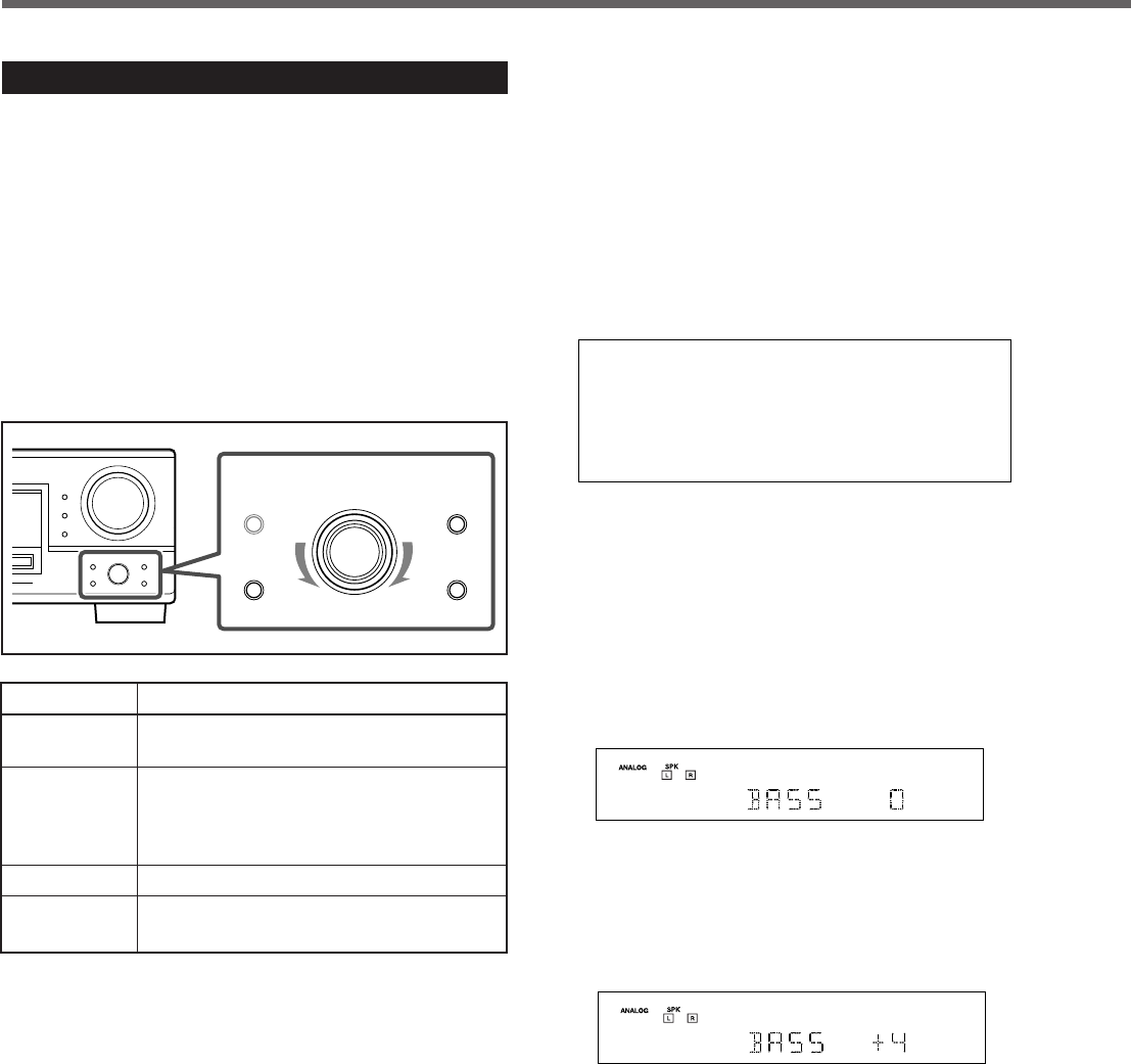
Sound Adjustments Using MULTI JOG Dial
You can adjust the sound using MULTI JOG dial on the front
panel.
• Tone—BASS, TREBLE
• Subwoofer output level*—SUBWFR LEVEL
• Speakers’ output level*—
FRONT L/R LEVEL, CENTER LEVEL, SURR L/R LEVEL
• Effect level for DAP modes—EFFECT
• Panorama control for Pro Logic II Music—PANORAMA
CTRL
*You can also use the remote control to adjust these items
(see pages 18 and 19).
7Operating buttons
Buttons To do
ADJUST Enter the receiver into the sound adjusting
mode.
MULTI JOG • Select an item to adjust after pressing
ADJUST.
• Adjust the selected item after pressing
SET.
SET Determine the item to adjust.
EXIT Exit from the sound adjusting mode or
return to the previous step.
7Operating procedure
Ex. When adjusting the bass sound
Before you start, remember...
There is a time limit in doing the following steps. If the setting
is canceled before you finish, start again from step
1
.
1
Press ADJUST.
The last selected item appears on the display.
2
Turn MULTI JOG dial to select an item you
want to adjust.
*
These items may not be selected depending on how the
following are set:
• Subwoofer setting
• Speaker size setting
• The current Surround/DSP mode
For details, see the next page and “Adjustable items and
selected Surround/DSP mode” on page 25.
3
Press SET.
The current setting of the selected item appears on the
display.
EX.: When “BASS” is selected.
4
Turn MULTI JOG dial to select an
appropriate value.
Adjust the bass sound level within the range of –10 dB to
+10 dB.
EX.: When the bass level is adjusted to “+4.”
5
Press EXIT.
To adjust other items, repeat steps
2
to
5
.
To finish the adjustment, go to step
6
.
6
Press EXIT again.
The receiver exits from the sound adjusting mode.
BASS TREBLE SUBWFR LEVEL*
FRONT L LEVEL FRONT R LEVEL
CENTER LEVEL*SURR L LEVEL*
SURR R LEVEL*EFFECT*
PANORAMA CTRL*(back to the beginning)
OO O
OO
O
O
OO
O
Sound Adjustments
SETTING MULTI JOG
SET
ADJUST
EXIT
16-21_RX-5032VSL[A]f.P65 03.3.26, 17:4517
18
7Panorama control for Pro Logic II Music—
PANORAMA CTRL (Control)
You can turn on or off the Panorama control for Pro Logic II
Music only when “PL II MUSIC” is activated.
Select “PANORAMA ON” to enjoy “wraparound” sound effect
with side-wall image (“OFF” is the initial setting).
• For Pro Logic II Music, see page 22.
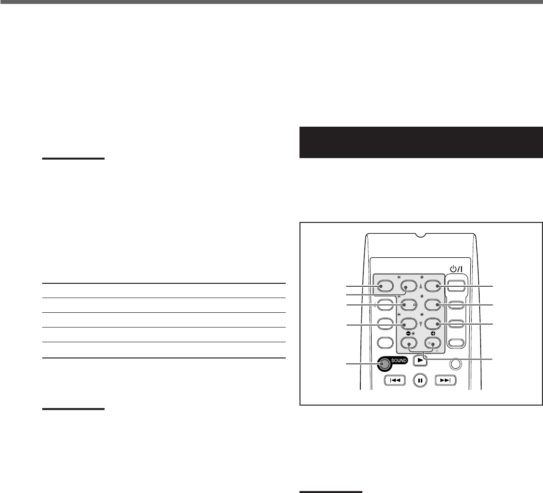
Sound Adjustments Using Remote
Control
You can also use the remote control to adjust the speaker
output levels and the subwoofer output level.
• You can use the test tone to make your favourite adjustments
(except for subwoofer level adjustment).
Adjusting Speaker Output Levels Using Test
Tone
The center and surround speakers are temporarily activated
and you can adjust them when you are listening to stereo
sound or one of the DAP modes is activated.
Notes:
•You cannot adjust the center speaker output level when the center
speaker size is set to “NONE” (see page 13).
•You cannot adjust the surround speaker output levels when the
surround speaker size is set to “NONE” (see page 13).
1
Press SOUND.
The 10 keys are activated for sound adjustments.
TEST
CENTER
FRONT L
SURR L
SOUND
FRONT R
SURR R
SUBWFR
LEVEL
9/(
Sound Adjustments
7Tone—BASS, TREBLE
Adjust the bass and treble sounds as you like (–10 dB to +10 dB
in 2 step intervals).
• “0” is the initial setting.
7Subwoofer output level—SUBWFR (Subwoofer) LEVEL
Adjust the subwoofer output level (–10 dB to +10 dB in 1 step
intervals).
• “0” is the initial setting.
Note:
Subwoofer output level cannot be adjusted in the following cases:
•When “SUBWOOFER NO” is selected for the subwoofer setting (see
page 13).
•When the HEADPHONE mode is in use (see page 11).
7Speakers’ output level
Adjust the speakers’ output level so that you can hear sounds
from each speaker at an equal level (–10 dB to +10 dB in 1
step intervals).
• “0” is the initial setting for all speakers.
FRONT L LEVEL Left front speaker output level
FRONT R LEVEL Right front speaker output level
CENTER LEVEL*Center speaker output level
SURR L LEVEL*Left surround speaker output level
SURR R LEVEL*Right surround speaker output level
*
You can adjust these items depending on the current speaker
settings (see page 13) and Surround/DSP mode (see “Adjustable
items and selected Surround/DSP mode” on page 25).
Notes:
•You cannot adjust the center speaker output level when the center
speaker size is set to “NONE” (see page 13).
•You cannot adjust the surround speaker output levels when the
surround speaker size is set to “NONE” (see page 13).
7Effect level for DAP modes—EFFECT
You can adjust the effect level for DAP modes only when one
of the DAP modes is activated (EFFECT 1 to EFFECT 5).
“EFFECT 3” is the initial setting. As the number increases, the
effect becomes more stronger.
• For DAP modes, see page 23.
TO BE CONTINUED TO THE NEXT PAGE
LEVEL
SURR RSURR L
SUBWFRCENTER
FRONT RFRONT L
7/P
10
2
5
8
0
3
6
9
10
A/V CONTROL
RECEIVER
TEST
4
1
100
16-21_RX-5032VSL[A]f.P65 03.3.26, 17:4518
19
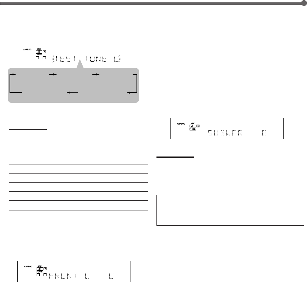
2
Press TEST.
“TEST TONE L” starts flashing on the display and a test
tone comes out of the speakers in the following order:
Check whether you can hear the tone through all the
speakers at an equal level or not.
Note:
If the center and surround speakers are set to “NONE,” no test
tone is available.
3
Select a speaker you want to adjust.
Press one of the following buttons:
FRONT L Left front speaker
FRONT R Right front speaker
CENTER Center speaker
SURR L Left surround speaker
SURR R Right surround speaker
4
Press LEVEL 9/( to adjust the selected
speaker output level (–10 dB to +10 dB).
When you press the button once, the current setting of the
selected speaker appears on the display and a test tone
comes out of the selected speaker.
• “0” is the initial setting for all speakers.
Ex.: When you press FRONT L in step
3
.
Repeat steps
3
and
4
to adjust other speaker output
levels so that you can hear the tone through all the
speakers at an equal level.
5
Press SOUND, then press TEST to stop the
test tone.
Adjusting Subwoofer Output Level
Make sure the subwoofer setting is set to “YES” (see page 13).
1
Press SOUND.
The 10 keys are activated for sound adjustments.
2
Press SUBWFR.
3
Press LEVEL 9/( to adjust the subwoofer
output level (–10 dB to +10 dB).
When you press the button once, the current setting of the
subwoofer appears on the display.
• “0” is the initial setting.
Note:
Subwoofer output level cannot be adjusted in the following cases:
•When “SUBWOOFER NO” is selected for the subwoofer setting (see
page 13).
•When the HEADPHONE mode is in use (see page 11).
When you use the 10 keys to operate your target
source after sound adjustments, press the source
selection button first so that the 10 keys work for the
target source.
Sound Adjustments
TEST TONE L TEST TONE C TEST TONE R
(Left front speaker) (Right front speaker)
(Left surround speaker) (Right surround speaker)
(Center speaker)
TEST TONE LS TEST TONE RS
16-21_RX-5032VSL[A]f.P65 03.3.26, 17:4519
20
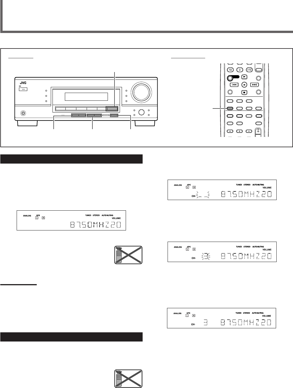
2
Press MEMORY.
The CH– indicator lights up and the channel number
position will flash on the display for about 5 seconds.
Ex.: When the FM band is selected in step
1
.
3
Press FM/AM PRESET 5/∞ to select a
channel number while the channel number
position is flashing.
Ex.: When channel number “3” is selected.
4
Press MEMORY again while the selected
channel number is flashing on the display.
The selected channel number stops flashing.
The station is assigned to the selected channel number.
5
Repeat steps
1
to
4
until you store all the
stations you want.
To erase a stored preset station, store a new station on a
used number.
The station previously stored will be erased.
Tuner Operations
Tuning in to Stations Manually
1
Press FM/AM to select the band (FM or AM).
The last received station of the last selected band is tuned
in.
• Each time you press the button, the band alternates
between FM and AM.
Ex.: When the FM band is selected.
2
Press FM/AM TUNING 5/∞ on the
front panel repeatedly until you
find the frequency you want.
Notes:
•When you hold FM/AM TUNING
5
/
∞
in step
2
, the frequency keeps
changing until a station is tuned in.
•When a station of sufficient signal strength is tuned in, the TUNED
indicator lights up on the display.
•When an FM stereo program is received, the STEREO indicator also
lights up.
Using Preset Tuning
Once a station is assigned to a channel number, the station
can be quickly tuned in. You can preset up to 30 FM and
15 AM stations.
Storing the Preset Stations
Before you start, remember...
There is a time limit in doing the following steps. If the setting
is canceled before you finish, start again from step
2
.
1
Tune in to the station you want to preset
(see “Tuning in to Stations Manually”).
If you want to store the FM reception mode for this station,
select the FM reception mode you want. See “Selecting
the FM Reception Mode” on page 21.
FM/AM
TUNING 5/∞
FM/AM
PRESET 5/∞
FM/AM
Remote
NOT
MEMORY
Front panel Remote control
FM/AM
Remote
NOT
AUDIO/VIDEO CONTROL RECEIVER
RX–5032V
16-21_RX-5032VSL[A]f.P65 03.3.26, 17:4520
21
Tuning in to a Preset Station
On the front panel
1
Press FM/AM to select the band (FM or AM).
The last received station of the last selected band is tuned
in.
• Each time you press the button, the band alternates
between FM and AM.
2
Press FM/AM PRESET 5/∞ repeatedly until
you find the channel you want.
From the remote control
1
Press FM/AM to select the band (FM or AM).
The last received station of the last selected band is tuned
in and the 10 keys now work for the tuner operation.
• Each time you press the button, the band alternates
between FM and AM.
2
Press 10 keys (1 – 10, +10) to select a preset
channel number.
• For channel number 5, press 5.
• For channel number 15, press +10 then 5.
• For channel number 20, press +10 then 10.
• For channel number 30, press +10, +10, then 10.
Note:
When you use 10 keys, be sure that they are activated for the tuner,
not for the CD or other functions. (See page 29.)
Tuner Operations
Front panel Remote control
FM MODE
FM MODE
10 keys
FM/AM
FM/AM
PRESET 5/∞
FM/AM
A/V CONTROL
RECEIVER
Selecting the FM Reception Mode
When an FM stereo broadcast is hard to receive or noisy, you
can change the FM reception mode.
• You can store the FM reception mode for each preset
station. (See page 20.)
Press FM MODE while listening to an FM station.
• Each time you press the button, the FM reception mode
alternates between “AUTO” and “MONO.”
AUTO Normally select this (initial setting).
When a program is broadcast in stereo, you will
hear stereo sound; when in monaural, you will
hear monaural sound. This mode is also useful to
suppress static noise between stations. The
AUTO MUTING indicator lights up on the display.
MONO Select this to improve the reception (but stereo
effect will be lost).
In this mode, you will hear noise while tuning in to
the station. The AUTO MUTING indicator goes off
on the display. (The STEREO indicator goes off.)
AUDIO/VIDEO CONTROL RECEIVER
RX–5032V
16-21_RX-5032VSL[A]f.P65 03.3.26, 17:4521
22
Dolby Digital 5.1 channel encoding method (so-called
discrete multi-channel digital audio format) records and
digitally compresses the left front channel, right front channel,
center channel, left surround channel, right surround channel,
and LFE channel signals.
Since each channel is completely independent from the other
channel signals to avoid interference, you can obtain much
better sound quality with many stereo and surround effects.
• When Dolby Digital signal comes in, the DIGITAL
indicator lights up on the display.
Note:
Dolby Digital software can roughly be grouped into two categories
—multi-channel (up to 5.1 channel) and 2 channel software. To enjoy
surround sounds while playing Dolby Digital 2 channel software, you
can use Dolby Pro Logic II.
7 DTS Digital Surround**
Used to reproduce multi-channel sound tracks of software
encoded with DTS Digital Surround ( ).
• To use software encoded with DTS Digital Surround, connect
the source component to the digital terminal on the rear of
this receiver. (See page 9.)
DTS Digital Surround is another discrete multi-channel
digital audio format available on CD, LD, and DVD software.
Compared to Dolby Digital, the audio compression ratio is
relatively low. This fact allows DTS Digital Surround format to
add breadth and depth to the reproduced sounds. As a result,
DTS Digital Surround features natural, solid, and clear sound.
• When DTS signal comes in, the indicator lights up on
the display.
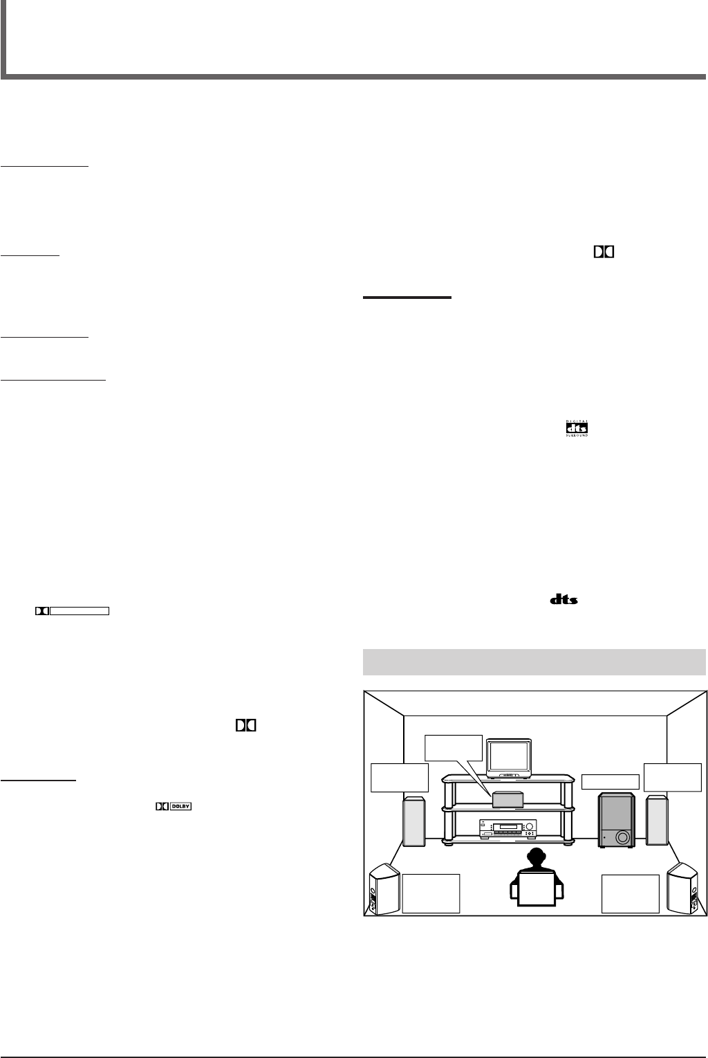
Typical multi-channel (5.1 channel) reproduction
**
“DTS” and “DTS Digital Surround” are registered trademarks of
Digital Theater Systems, Inc.
*
Manufactured under license from Dolby Laboratories. “Dolby”,
“Pro Logic”, and the double-D symbol are trademarks of Dolby
Laboratories.
You can use the following Surround and DSP modes to
reproduce a realistic sound field:
Surround modes
7Dolby
• Dolby Pro Logic II
• Dolby Digital
7DTS Digital Surround
DSP modes
7DAP modes
7All Channel Stereo
Surround modes
7 Dolby
Dolby Pro Logic II*
Dolby Pro Logic II has a multi-channel playback format to
decode all 2 channel sources—stereo source and Dolby
Surround encoded source—into 5.1 channels.
Matrix-based encoding/decoding method for Dolby Pro Logic II
makes no limitation for the cutoff frequency of the rear treble
and enables stereo rear sound compared to conventional Dolby
Pro Logic.
Dolby Pro Logic II enables reproduction of spacious sound
from original sound without adding any new sounds and tonal
colorations.
Dolby Pro Logic II has two modes—Movie mode and Music
mode:
Pro Logic II Movie (PL II MOVIE)—suitable for the
reproduction of Dolby Surround encoded sources bearing the
mark
DOLBY SURROUND
. You can enjoy a sound field very close to
the one created with discrete 5.1 channel sounds.
Pro Logic II Music (PL II MUSIC)—suitable for the
reproduction of any 2 channel stereo music sources. You can
enjoy wide and deep sound by using this mode. For this mode,
Panorama control can be selected, which gives “wraparound”
sound effect with side-wall image.
• When Dolby Pro Logic II is activated, the PRO LOGIC II
indicator lights up on the display.
Dolby Digital*
Used to reproduce multi-channel sound tracks of the software
encoded with Dolby Digital (
DIGITAL
).
• To use software encoded with Dolby Digital, connect the
source component to the digital terminal on the rear of this
receiver. (See page 9.)
Creating Realistic Sound Fields
Left front
speaker Subwoofer
Center
speaker
Left
surround
speaker
Right
surround
speaker
Right front
speaker
22-25_RX-5032VSL[A]f.P65 03.3.26, 17:4522
23
DSP modes
7 DAP (Digital Acoustic Processor) modes
DAP modes have been designed to create important acoustic
surround elements.
The sound heard in a live club, dance club, hall or pavilion
consists of direct sound and indirect sound—early reflections
and reflections from behind. Direct sounds reach the listener
directly without any reflection. On the other hand, indirect
sounds are delayed by the distances of the ceiling and walls
(see the diagram on the right).
These indirect sounds are important elements of the acoustic
surround effects. The DAP mode can reproduce a realistic
sound field by adding these indirect sounds.
DAP modes can be used when the front and surround
speakers are connected to this receiver (without respect
to the center speaker connection: no sound comes out of
the center speaker even if it is connected).
The following DAP modes are provided with this receiver:
LIVE CLUB Gives the feeling of a live music club with a
low ceiling.
DANCE CLUB Gives a throbbing bass beat.
HALL Gives clear vocal and the feeling of a concert
hall.
PAVILION Gives the spacious feeling of a pavilion with a
high ceiling.
These DAP modes can be used to add the acoustic surround
effects while reproducing 2 channel stereo software—either
analog or digital except Dolby Digital and DTS Digital
Surround—and can give you a real “being there” feeling.
• When one of the DAP modes is selected, the DSP indicator
lights up on the display.
Modes SURROUND DOLBY DTS PL II PL II LIVE DANCE HALL PAVILION ALL CH
Signals OFF (stereo) DIGITAL SURROUND MOVIE MUSIC CLUB CLUB STEREO
Dolby Digital 䡬䡬⳯⳯⳯⳯⳯⳯⳯⳯
(Multi-channel)
Dolby Digital 䡬⳯⳯䡬䡬⳯⳯⳯⳯⳯
(2 channel)
DTS Digital
Surround 䡬⳯䡬⳯⳯⳯⳯⳯⳯⳯
(Multi-channel)
DTS Digital
Surround 䡬⳯⳯䡬䡬⳯⳯⳯⳯⳯
(2 channel)
Linear PCM 䡬 ⳯ ⳯ 䡬 䡬䡬䡬 䡬䡬䡬
Analog 䡬 ⳯ ⳯ 䡬 䡬䡬䡬 䡬䡬䡬
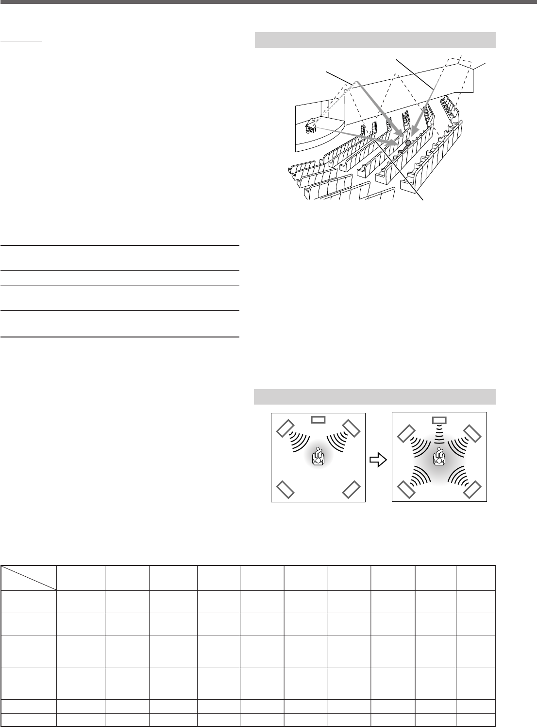
7 All Channel Stereo
This mode can reproduce a larger stereo sound field using all
the connected (and activated) speakers.
All Channel Stereo can be used when the front and
surround speakers are connected to this receiver without
respect to the center speaker connection.
If the center speaker is connected and activated, the same
phase of the front left and right signals is emitted through the
center speaker.
All Channel Stereo can be used while reproducing 2 channel
stereo software, either analog or digital except Dolby Digital
and DTS.
• When All Channel Stereo is selected, the DSP indicator
lights up on the display.
All Channel Stereo reproduction
Available Surround/DSP modes for each input signal 䡬: Available ⳯: Not available
Sound reproduced from
All Channel Stereo
Normal stereo reproduction
Direct sounds
Reflections from behind
Early reflections
Creating sound field
Creating Realistic Sound Fields
22-25_RX-5032VSL[A]f.P65 03.3.26, 17:4523
24
Make sure that you have set the speaker information correctly (see pages 13 and 14).
• If only the front speakers are connected, you cannot use Surround/DSP modes.
• You cannot use DSP modes if no surround speakers are connected.
• Do not change the speaker setting while using any Surround/DSP modes; otherwise, the Surround/DSP modes may be
canceled when you deactivate the speakers required for the Surround/DSP modes.
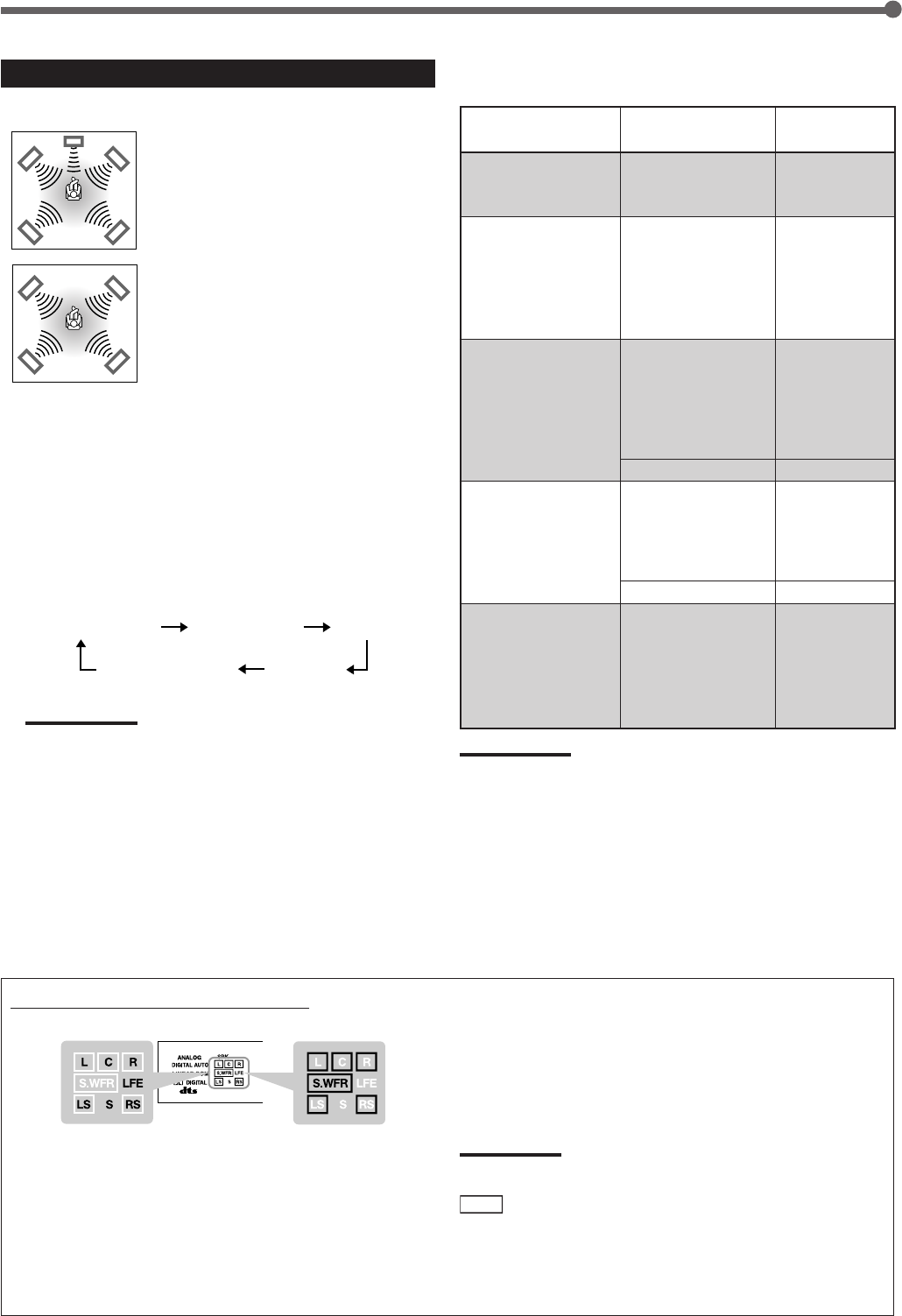
Using Surround Modes
Speaker layouts required for Surround modes are as follows:
• 5 channels
(Front, center, and surround speakers
are connected.)
• 4 channels
(Front and surround speakers are
connected.)
• 3 channels
(Front and center speakers are
connected.)
7Operating procedure
1
Select the source you want to listen to and
start playing.
• When playing back software encoded with Dolby Digital
and DTS Digital Surround, select the digital input mode
(see page 15).
SURROUND/DSP
OFF
DSP
SURROUND/DSP OFF
SURROUNDDSP
Front panel Remote control
SURROUND
2
Press SURROUND.
The appropriate Surround mode will be activated
according to the incoming signal.
• DOLBY DIGITAL:
Activated if you are playing back multi-channel
software encoded with Dolby Digital.
• DTS SURROUND:
Activated if you are playing back software encoded
with DTS Digital Surround.
• PL II MUSIC* or PL II MOVIE:
Activated if you are playing back any software other
than the above. (The last one selected will be
activated.)
The PRO LOGIC II indicator lights up on the
display.
Press SURROUND repeatedly to select the one
appropriate for the source.
*
When “PL II MUSIC” is selected, you can select Panorama
control to enjoy “wraparound” sound effect with side-wall image
(see pages 17 and 18 for the setting procedure).
Notes:
•When “DOLBY DIGITAL” or “DTS SURROUND” is selected with
no surround speakers connected, the surround sounds are
downmixed and output from the front speakers.
•For the available Surround modes according to the input signals,
see “Available Surround/DSP modes for each input signal” on
page 23.
To adjust the speaker output level and select Panorama
control for Pro Logic II Music, see pages 17 to 19.
The adjustment is memorized for each source (except for
Panorama control).
To turn off Surround mode, press SURROUND/DSP OFF.
Creating Realistic Sound Fields
SURROUND/DSP
RX–5032V
AUDIO/VIDEO CONTROL RECEIVER
DISPLAY MODE
22-25_RX-5032VSL[A]f.P65 03.3.26, 17:4524
25
Signal and speaker indicators on the display
Signal indicators Speaker indicators
The following signal indicators light up—:
L: • When digital input is selected: Lights up when the left
channel signal comes in.
• When analog input is selected: Always lights up.
R: • When digital input is selected: Lights up when the
right channel signal comes in.
• When analog input is selected: Always lights up.
C: When the center channel signal comes in.
Using DSP Modes
Speaker layouts required for the DSP modes are as follows:
• 5 channels
(Front, center, and surround speakers
are connected.)
• 4 channels
(Front and surround speakers are
connected.)
7Operating procedure
1
Start playing 2 channel software—either
analog or Linear PCM—and select the
source.
2
Press DSP.
The last selected DSP mode will be activated and the DSP
indicator lights up on the display.
• Each time you press the button, the DSP mode changes
as follows:
Note:
For the available DSP modes according to input signals, see
“Available Surround/DSP modes for each input signal” on page
23.
To adjust the speaker output level and the effect level for
DAP mode, see pages 17 to 19.
The adjustment is memorized for each source (except for the
effect level).
To turn off DSP mode, press SURROUND/DSP OFF.
LIVE CLUB DANCE CLUB HALL
PAVILIONALL CH STEREO
(All Channel Stereo)
7Adjustable items and selected Surround/DSP mode
• For adjustment operation, see pages 17 to 19.
Selected Surround/
DSP mode
SURROUND OFF
(stereo)
DOLBY DIGITAL,
DTS SURROUND,
PL II MOVIE
PL II MUSIC
LIVE CLUB,
DANCE CLUB,
HALL,
PAVILION
ALL CH STEREO
(All Channel Stereo)
Adjustable items
FRONT L LEVEL
FRONT R LEVEL
SUBWFR LEVEL
FRONT L LEVEL
FRONT R LEVEL
CENTER LEVEL
SURR L LEVEL
SURR R LEVEL
SUBWFR LEVEL
FRONT L LEVEL
FRONT R LEVEL
CENTER LEVEL
SURR L LEVEL
SURR R LEVEL
SUBWFR LEVEL
PANORAMA CTRL
FRONT L LEVEL
FRONT R LEVEL
SURR L LEVEL
SURR R LEVEL
SUBWFR LEVEL
EFFECT
FRONT L LEVEL
FRONT R LEVEL
CENTER LEVEL
SURR L LEVEL
SURR R LEVEL
SUBWFR LEVEL
Adjustable
range
–10 to +10
–10 to +10
–10 to +10
ON “ OFF
–10 to +10
1 to 5
–10 to +10
LS: When the left surround channel signal comes in.
RS: When the right surround channel signal comes in.
S: When the monaural surround channel signal comes in.
LFE: When the LFE channel signal comes in.
The speaker indicators light up when the corresponding
speaker is connected and activated.
Note:
When “SUBWOOFER YES” is selected for the subwoofer setting
(see page 13) and the subwoofer output is turned on (see page 16),
S.WFR
lights up.
Notes:
•Regardless of the selected Surround/DSP mode,
–You cannot adjust the center speaker output level when the center
speaker size is set to “NONE” (see page 13).
–You cannot adjust the surround speaker output levels when the
surround speaker size is set to “NONE” (see page 13).
•You cannot adjust the subwoofer output level when “SUBWOOFER
NO” is selected for the subwoofer setting (see page 13).
Creating Realistic Sound Fields
22-25_RX-5032VSL[A]f.P65 03.3.26, 17:4625
26
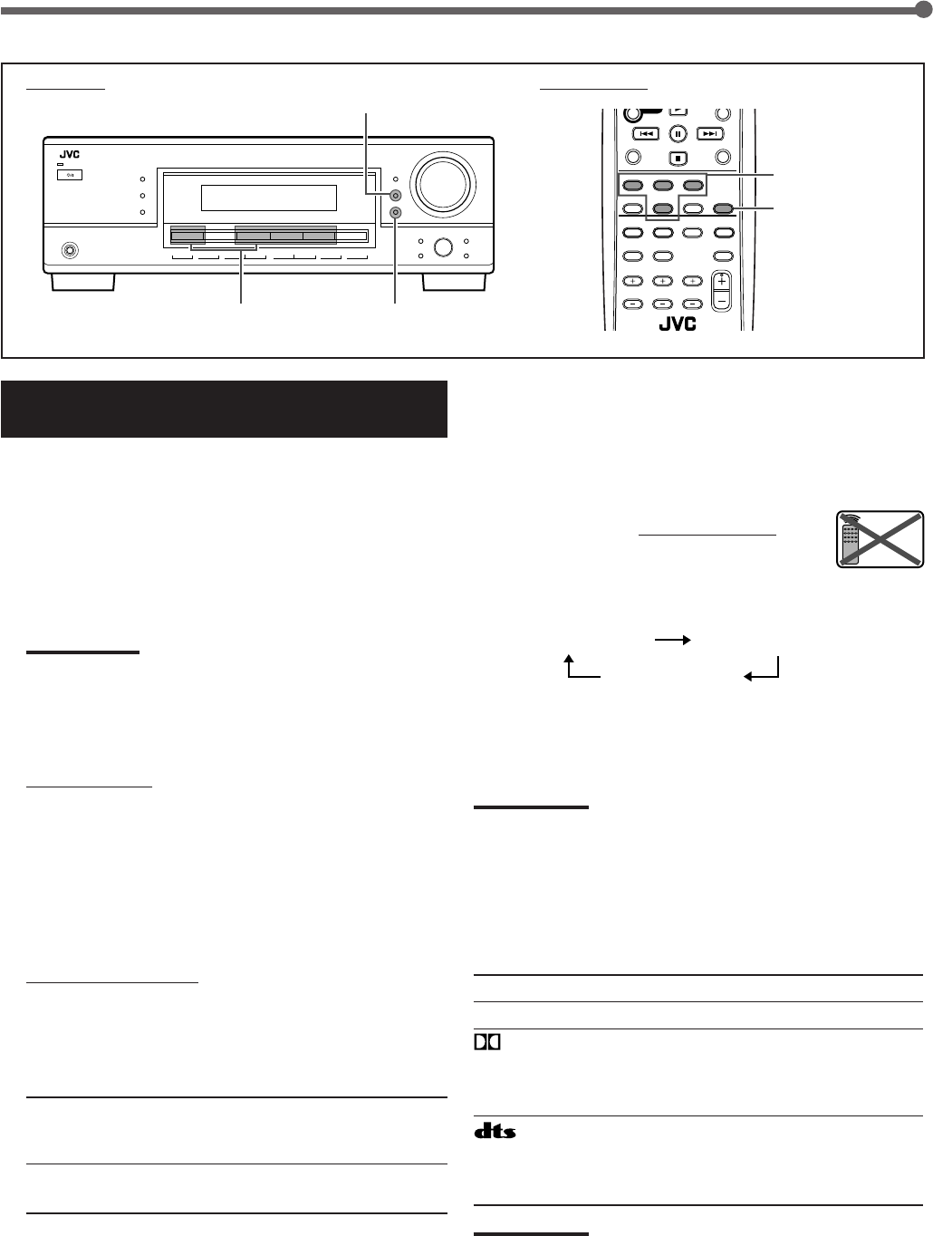
The COMPU LINK remote control system allows you to
operate JVC’s audio components through the remote sensor
on the receiver.
To use this remote control system, you need to connect JVC’s
audio components through the COMPU LINK (SYNCHRO)
jacks (see below) in addition to the connections using cables
with RCA pin plugs (see page 7).
• Make sure that the AC power cords of these components are
unplugged before connection. Plug in the AC power cords
only after all other connections are completed.
Cassette deck CD player
Rear panel
Notes:
• There are four versions of the COMPU LINK remote control system.
This receiver is equipped with the fourth version—COMPU LINK-4.
This version adds systematic operations with the CD recorder to the
previous version—COMPU LINK-3.
• If your audio component has two COMPU LINK jacks, you can use
either one. If it has only one COMPU LINK jack, connect it so that it
is the last item in the series of components.
• To operate the cassette deck or CD recorder using the COMPU
LINK remote control system, set the source name correctly.
(See page 10.)
• Refer also to the manuals supplied with your audio components.
This remote control system allows you to use the four
functions listed below.
Remote Control through the Remote Sensor on the Receiver
You can control the connected audio components through the
remote sensor on the receiver using this remote control. Aim
the remote control directly at the remote sensor on the
receiver. For details, see pages 29 and 30.
COMPU LINK Remote Control System
Automatic Source Selection
When you press the play (3) button on a connected
component or on its own remote control, the receiver
automatically turns on and changes the source to the
component. On the other hand, if you select a new source on
the receiver or on the remote control, the selected component
begins playing immediately.
In both cases, the previously selected source continues
playing without sound for a few seconds.
Automatic Power On/Off (Standby): only possible with the
COMPU LINK-3 and COMPU LINK-4
Both the CD player and cassette deck (or CD recorder) turn
on and off (standby) along with the receiver.
When you turn on the receiver, the CD player or cassette deck
(or CD recorder) will turn on automatically, depending on
which component has been previously selected.
When you turn off the receiver, both the CD player and
cassette deck (or CD recorder) will turn off (standby).
Synchronized Recording
Synchronized recording means the cassette deck starts
recording as soon as a CD begins playing.
To use synchronized recording, follow these steps:
1
Put a tape in the cassette deck and a disc in
the CD player.
2
Press the record (¶) button and the pause
(8) button on the cassette deck at the same
time.
This puts the cassette deck into recording pause.
If you do not press the record (¶) button and pause (8)
button at the same time, the synchronized recording
feature will not operate.
3
Press the play (3) button on the CD player.
The source changes on the receiver, and as soon as play
starts, the cassette deck starts recording. When the play
ends, the cassette deck enters recording pause, and stops
about 4 seconds later.
Notes:
• During synchronized recording, the selected source cannot be
changed.
• If the power of any component is shut off during synchronized
recording, the COMPU LINK remote control system may not operate
properly. In this case, you must start again from the beginning.
RIGHT
COMPU LINK-4
(SYNCHRO)
26-34_RX-5032VSL[A]f.P65 03.3.26, 17:4626
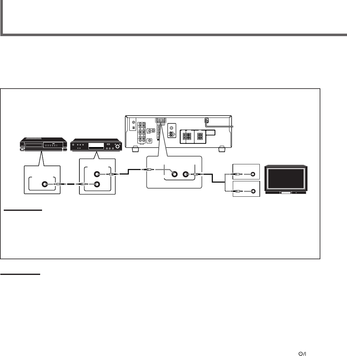
27
The AV COMPU LINK remote control system allows you to operate JVC’s video components (TV, VCR, and DVD player) through
the receiver.
To use this remote control system, you need to connect the video components you want to operate following the diagrams and
the procedure below.
7AV COMPU LINK connection
Note:
You can connect to the TV with the AV COMPU LINK EX or AV COMPU LINK III terminal.
A TV with AV COMPU LINK RECEIVER/AMP terminal can not be used.
7Video cable connection
Connect the DVD player and/or the VCR to this receiver using the VIDEO (composite video) terminals, and connect this
receiver to the TV’s Video Input 2 terminals (composite video input) using composite video cables.
AV COMPU LINK Remote Control System
Notes:
• When connecting only the VCR or DVD player to this receiver,
connect it directly to the receiver using cables with the monaural
mini-plugs.
• Make sure that the remote control code of the VCR connected to the
VCR jacks is set to code “A.”
• Refer also to the manuals supplied with your video components.
7Connecting procedure
1
If you have already plugged your VCR, DVD
player, TV and this receiver into the AC
outlets, unplug their AC power cords first.
2
Connect your VCR, DVD player, TV and this
receiver as illustrated above, using the
cables with monaural mini-plugs (not
supplied).
3
Connect the audio/video input/output jacks
on VCR, DVD player, TV and this receiver
(see page 8).
4
Plug the AC power cords of the components
into the AC outlets.
5
When turning on the TV for the first time
after the AV COMPU LINK connection, turn
the TV volume to the minimum using the TV
volume control on the TV.
6
Turn on the other connected components
first, then turn on this receiver.
• When turning on the VCR, use the remote control
supplied with this receiver (press STANDBY/ON
VCR).
TV
VCR DVD player
Rear panel
RIGHT
AV
COMPU LINK
VHS
AV
COMPU LINK
AV
COMPU LINK EX
DVD
AV
COMPU LINK III
AV
COMPU LINK
26-34_RX-5032VSL[A]f.P65 03.3.26, 17:4627

28
AV COMPU LINK Remote Control System
Automatic Selection of the TV Input Mode
• When you select “TV SOUND” as the source to play on the
receiver, the TV automatically changes the input mode to the
TV tuner so that you can watch TV.
• When you select “DVD” or “VCR” as the source to play on
the receiver, the TV automatically changes the input mode to
the appropriate position so that you can view the playback.
Automatic Power On/Off
The TV, VCR, and DVD player turn on and off along with the
receiver.
When you turn on the receiver;
• If the previously selected source is “VCR,” the TV and VCR
will turn on automatically.
• If the previously selected source is “TV SOUND,” only the TV
will turn on automatically.
• If the previously selected source is “DVD,” the TV and DVD
player will turn on automatically.
When you turn off the receiver, the TV, VCR, and DVD player
will turn off.
Note:
If you turn off the receiver while recording on the VCR, the VCR will
not turn off, but continue recording.
The AV COMPU LINK remote control system allows you to
use the five basic functions listed below.
Remote Control of the TV, DVD player, and VCR using this
Remote Control
See page 31 for details.
• Aim the remote control directly at the remote sensor on each
target component.
One-Touch Video Play
Simply by inserting a video cassette without its safety tab into
the VCR, you can start video playback without setting other
switches manually. The receiver automatically turns on and
changes the source to “VCR.”
The TV automatically turns on and changes the input mode to
the position so that you can view the playback.
When you insert a video cassette with its safety tab, press the
play (3) button on the VCR or on the remote control to get the
same result.
One-Touch DVD Play
Simply by starting playback on the DVD player, you can view
the DVD playback without setting other switches manually.
• When the DVD player is connected through the analog input
jacks on this receiver (and analog input is selected), the
receiver automatically turns on and changes the source to
“DVD.”
• When the DVD player is connected through the digital input
terminal on this receiver (and digital input is selected), the
receiver automatically turns on and changes the source to
“DVD DIGITAL.”
• The TV automatically turns on and changes the input mode
to the appropriate position so that you can view the
playback.
26-34_RX-5032VSL[A]f.P65 03.3.26, 17:4628
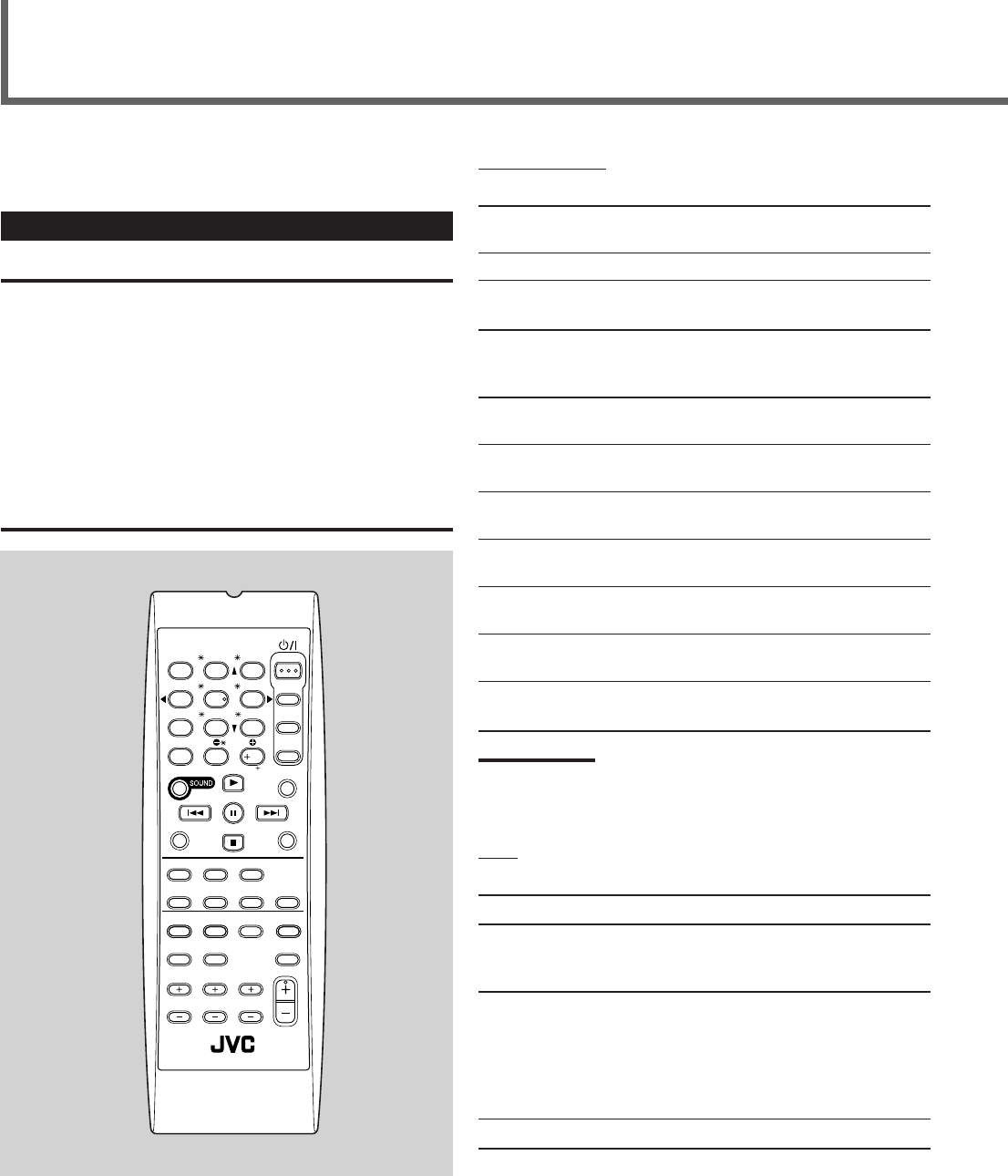
29
Operating JVC’s Audio/Video Components
You can use the remote control to operate other JVC
components.
Operating Audio Components
IMPORTANT:
To operate JVC’s audio components using this remote control:
• You need to connect JVC’s audio components through the COMPU
LINK (SYNCHRO) jacks (see page 26) in addition to the
connections using cables with RCA pin plugs (see page 7).
• Aim the remote control directly at the remote sensor on the receiver.
• If you use the buttons on the front panel, the remote control will not
operate that source. To operate a source with the remote control, the
source must be selected using source selection buttons on the
remote control.
• To operate the cassette deck or CD recorder using the COMPU
LINK remote control system, set the source name correctly. (See
page 10.)
• Refer also to the manuals supplied with your audio components.
Sound Adjustment
You can always use the following buttons:
SURROUND Turn on and select the Surround
modes.
DSP Turn on and select the DSP modes.
SURROUND/DSP OFF Turn off the Surround or DSP
modes.
After pressing SOUND, you can use the following buttons for
the sound adjustment:
SUBWFR =LEVEL 9/(Adjust the subwoofer output
level.
FRONT L =LEVEL 9/(Adjust the left front speaker
output level.
FRONT R =LEVEL 9/(Adjust the right front speaker
output level.
CENTER =LEVEL 9/(Adjust the center speaker
output level.
SURR L =LEVEL 9/(Adjust the left surround speaker
output level.
SURR R =LEVEL 9/(Adjust the right surround
speaker output level.
TEST Turn on or off the test tone
output.
Note:
When you use the 10 keys to operate your target source after sound
adjustments, press the source selection button first so that the 10
keys work for the target source.
Tuner
You can always use the following buttons:
FM/AM Alternate between FM and AM.
After pressing FM/AM, you can use the following buttons for
the tuner operations:
1 – 10, +10 Select a preset channel number directly.
• For channel number 5, press 5.
• For channel number 15, press +10, then
5.
• For channel number 20, press +10, then
10.
FM MODE Change the FM reception mode.
AUDIO
TV
VCR
DVD
TEST
MENU
ENTER LEVEL
RETURN
SURROUND
/DSP
CD-DISC
SLEEP
REC PAUSE
FM MODE
SURROUND
DSP
DIMMER TV/VIDEO MUTING
OFF
VCR CH
TV CH
VOLUME
SURR RSURR L
SUBWFRCENTER
FRONT RFRONT L
100
1
4
7/P
10
2
5
8
0
3
6
9
10
REMOTE CONTROL RM-SRX
5032U
REW FF
TV VOLUME
STANDBY/ON
A/V CONTROL
RECEIVER
TAPE/CDR CD DVD
FM/AM TV SOUND VCR ANALOG
/DIGITAL
26-34_RX-5032VSL[A]f.P65 03.3.26, 17:4629
30
CD player
After pressing CD, you can use the following buttons for the
CD operations:
3Start playback.
4Return to the beginning of the current
(or previous) tracks.
¢Skip to the beginning of the next tracks.
7Stop playback.
8Pause playback. To release, press 3.
1 – 10, +10 Select a track number directly.
• For track number 5, press 5.
• For track number 15, press +10, then 5.
• For track number 20, press +10, then 10.
CD changer
After pressing CD-DISC, you can use the following buttons for
the CD changer operations:
3Start playback.
4Return to the beginning of the current
(or previous) tracks.
¢Skip to the beginning of the next tracks.
7Stop playback.
8Pause playback. To release, press 3.
1 – 6, 7/P Select the number of a disc installed in a CD
changer.
After pressing CD, you can use the following buttons for the
CD changer operations:
1 – 10, +10 Select a track number directly.
• For track number 5, press 5.
• For track number 15, press +10, then 5.
• For track number 20, press +10, then 10.
• For track number 30, press +10, +10, then 10.
Example:
Selecting disc number 4, track number 12, and starting
playback.
1
Press CD-DISC, then press 4.
2
Press CD, then press +10, 2.
Operating JVC’s Audio/Video Components
Cassette deck
After pressing TAPE/CDR, you can use the following buttons
for the cassette deck operations:
3Start playback.
FF Fast wind a tape from left to right.
REW Fast wind a tape from right to left.
7Stop playback or recording.
8Pause playback. To release, press 3.
REC PAUSE Press this button to enter recording pause.
Press this button then 3 to start recording.
Note:
Before starting the above operations, make sure that you have
changed the source name correctly. See page 10.
CD recorder
After pressing TAPE/CDR, you can use the following buttons
for the CD recorder operations:
3Start playback.
4Return to the beginning of the current
(or previous) tracks.
¢Skip to the beginning of the next tracks.
7Stop playback.
8Pause playback. To release, press 3.
REC PAUSE Press this button to enter recording pause.
Press this button then 3 to start recording.
Note:
Before starting the above operations, make sure that you have
changed the source name correctly. See page 10.
26-34_RX-5032VSL[A]f.P65 03.3.26, 17:4630
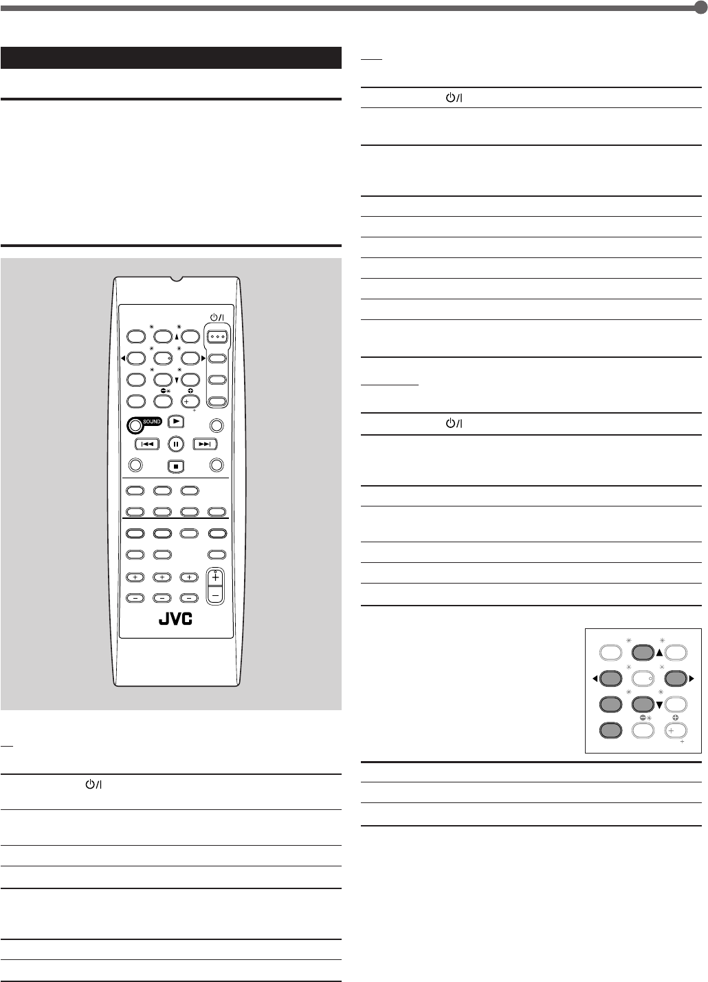
31
VCR
You can always use the following buttons:
STANDBY/ON VCR Turn on or off the VCR.
VCR CH +/–Change the TV channels on the
VCR.
After pressing VCR, you can use the following buttons for the
VCR operations:
3Start playback.
FF Fast wind a tape.
REW Rewind a tape.
7Stop playback or recording.
8Pause playback. To release, press 3.
1 – 9, 0 Select a TV channel on the VCR.
REC PAUSE Press this button to enter recording pause.
Press this button then 3 to start recording.
DVD player
You can always use the following buttons:
STANDBY/ON DVD Turn on or off the DVD player.
After pressing DVD, you can use the following buttons for the
DVD operations:
3Start playback.
4Return to the beginning of the current
(or previous) chapters.
¢Skip to the beginning of the next chapters.
7Stop playback.
8Pause playback. To release, press 3.
DVD menu operations
After pressing DVD, you can use the
following buttons for DVD menu
operations:
MENU Display or hide the menu screen.
5/∞/3/2Select an item on the menu screen.
ENTER (10) Enter a selected item.
Operating JVC’s Audio/Video Components
Operating Video Components
IMPORTANT:
To operate JVC’s video components using this remote control:
• You need to connect JVC’s video components through the AV
COMPU LINK terminals (see page 27) in addition to the connections
using cables with RCA pin plugs (see page 8).
• Some JVC VCRs can accept two types of control signals—remote
code “A” and “B.” Before using this remote control, make sure that
the remote control code of the VCR connected to the VCR jacks is
set to code “A.”
• When using the remote control, aim the remote control directly at
the remote sensor on each component, not on the receiver.
TV
You can always use the following buttons:
STANDBY/ON TV
Turn on or off the TV.
TV/VIDEO Change the input mode (TV tuner and
video input).
TV VOLUME +/–Adjust the volume.
TV CH +/–Change the channels.
After pressing TV SOUND, you can use the following buttons
for the TV operations:
1 – 9, 0, +10 (100+) Select a channel.
RETURN (10) Function as the RETURN button.
AUDIO
TV
VCR
DVD
TEST
MENU
ENTER LEVEL
RETURN
SURROUND
/DSP
CD-DISC
SLEEP
REC PAUSE
FM MODE
SURROUND
DSP
DIMMER TV/VIDEO MUTING
OFF
VCR CH
TV CH
VOLUME
SURR RSURR L
SUBWFRCENTER
FRONT RFRONT L
100
1
4
7/P
10
2
5
8
0
3
6
9
10
REMOTE CONTROL RM-SRX
5032U
REW FF
TV VOLUME
STANDBY/ON
A/V CONTROL
RECEIVER
TAPE/CDR CD DVD
FM/AM TV SOUND VCR ANALOG
/DIGITAL
TEST
MENU
ENTER LEVEL
RETURN
SURR RSURR L
SUBWFRCENTER
FRONT RFRONT L
100
1
4
7/P
10
2
5
8
0
3
6
9
10
TA/NEWS/INFO
26-34_RX-5032VSL[A]f.P65 03.3.26, 17:4631
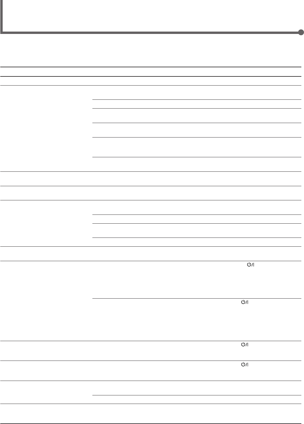
32
Troubleshooting
Use this chart to help you solve daily operational problems. If there is any problem you cannot solve, contact your JVC service
center.
SOLUTION
Plug the power cord into an AC outlet.
Check speaker wiring and reconnect if
necessary.
Select the correct source.
Press MUTING on the remote control to cancel
the mute.
Select the correct input mode (analog or
digital).
Check connections.
For analog connections, see pages 7 and 8.
For digital connections, see page 9.
Check speaker wiring and reconnect if
necessary.
Adjust the speaker output level (see pages 17
– 19).
Press SPEAKERS ON/OFF on the front panel
to activate the speakers (see page 12).
Connect an outdoor FM antenna or contact
your dealer.
Select a new station.
Check with your dealer to be sure you have the
correct antenna.
Check connections.
Move the antenna farther from automobile
traffic.
1. Press STANDBY/ON on the front panel
to turn off the receiver.
2. Stop the playback source.
3. Turn on the receiver again, and adjust the
volume.
Press STANDBY/ON on the front panel,
then check the speaker wiring.
If “OVERLOAD” does not disappear after
turning on the receiver again, unplug the AC
power cord, then plug it back in again.
If speaker wiring is not short-circuited, contact
your dealer.
Press STANDBY/ON on the front panel to
turn off the receiver. After unplugging the
power cord, consult your dealer.
Press STANDBY/ON on the front panel to
turn off the receiver. After unplugging the
power cord, consult your dealer.
Remove the obstruction.
Replace batteries in the remote control.
Press SOUND or source selection buttons first,
then press the button you want to use.
(See pages 18 and 29 – 31).
POSSIBLE CAUSE
The power cord is not plugged in.
Speaker signal cables are not
connected.
An incorrect source is selected.
Muting is activated.
An incorrect input mode (analog or
digital) is selected.
Connections are incorrect.
Speaker signal cables are not connected
properly.
The speaker output level is not set
correctly.
The speakers are deactivated.
Incoming signal is too weak.
The station is too far away.
The wrong antenna is being used.
Antennas are not connected properly.
Ignition noise from automobiles.
Speakers are overloaded because of
high volume.
Speakers are overloaded because of
short circuit of speaker terminals.
The built-in microcomputer is not
functioning correctly.
The receiver is overloaded because of a
high voltage.
There is an obstruction in front of the
remote sensor on the receiver.
Batteries are weak.
The remote control is not ready for your
intended operation.
PROBLEM
The power does not come on.
No sound from speakers.
Sounds from speakers are heard
unequally.
No test tone is available.
Continuous hiss or buzzing during FM
reception.
Occasional cracking noise during FM
reception.
“OVERLOAD” starts flashing on the
display.
“DSP MICOM NG” starts flashing on
the display.
The STANDBY lamp lights up after
turning on the power, but soon the
receiver turns off (into standby mode).
Remote control does not work.
Remote control does not operate as
you intend.
26-34_RX-5032VSL[A]f.P65 03.3.26, 17:4632

33
Specifications Designs & specifications are subject to change without notice.
Amplifier
Output Power: At Stereo operation:
Front channels: 100 W per channel, min. RMS, driven into 8 Ω at 1 kHz with no
more than 0.9% total harmonic distortion. (IEC268-3/DIN)
At Surround operation:
Front channels: 100 W per channel, min. RMS, driven into 8 Ω at 1 kHz with no
more than 0.8% total harmonic distortion.
Center channel: 100 W, min. RMS, driven into 8 Ω at 1 kHz, with no more than
0.8% total harmonic distortion.
Surround channels: 100 W per channel, min. RMS, driven into 8 Ω at 1 kHz, with no
more than 0.8% total harmonic distortion.
Audio
Audio Input Sensitivity/Impedance (1 kHz): CD, TAPE/CDR, VCR, TV SOUND, DVD: 220 mV/47 kΩ
Audio Input (DIGITAL IN)* : Coaxial: DIGITAL 1 (DVD): 0.5 V (p-p)/75 Ω
Optical: DIGITAL 2 (CD): –21 dBm to –15 dBm (660 nm ±30 nm)
*Corresponding to Linear PCM, Dolby Digital, and DTS Digital Surround
(with sampling frequency—32 kHz, 44.1 kHz, 48 kHz).
Audio Output Level: TAPE/CDR, VCR: 220 mV
Signal-to-Noise Ratio (’66 IHF/DIN): CD, TAPE/CDR, VCR, TV SOUND, DVD: 87 dB/67 dB
Frequency Response (8 Ω): CD, TAPE/CDR, VCR, TV SOUND, DVD: 20 Hz to 20 kHz (±1 dB)
Tone Control: Bass (100 Hz): ±10 dB
Treble (10 kHz): ±10 dB
Video
Video Input Sensitivity/Impedance:
Composite video: DVD, VCR: 1 V (p-p)/75 Ω
Video Output Level/Impedance:
Composite video: VCR, MONITOR OUT: 1 V (p-p)/75 Ω
Synchronization: Negative
Signal-to-Noise Ratio: 45 dB
26-34_RX-5032VSL[A]f.P65 03.3.26, 17:4633

34
Specifications
FM tuner (IHF)
Tuning Range: 87.50 MHz to 108.00 MHz
Usable Sensitivity: Monaural: 17.0 dBf (1.95 µV/75 Ω)
50 dB Quieting Sensitivity: Monaural: 21.3 dBf (3.2 µV/75 Ω)
Stereo: 41.3 dBf (31.5 µV/75 Ω)
Signal-to-Noise Ratio (IHF-A weighted): Monaural: 78 dB at 85 dBf
Stereo: 73 dB at 85 dBf
Total Harmonic Distortion: Monaural: 0.4% at 1 kHz
Stereo: 0.6% at 1 kHz
Stereo Separation at REC OUT: 35 dB at 1 kHz
Alternate Channel Selectivity: 45 dB: (±400 kHz)
Frequency Response: 30 Hz to 15 kHz: (+0.5 dB, –3 dB)
AM tuner
Tuning Range: 522 kHz to 1 629 kHz
Usable Sensitivity: Loop antenna: 400 µV/m
Signal-to-Noise Ratio: 50 dB (100 mV/m)
General
Power Requirements: AC 240 V , 50 Hz
Power Consumption: 200 W (at operation)
2 W (in standby mode)
Dimensions (W x H x D): 435 mm x 146.5 mm x 409.5 mm
Mass: 8.8 kg
26-34_RX-5032VSL[A]f.P65 03.3.26, 17:4634

0403NHMMDWJEIN
J
V
C
EN
© 2003 VICTOR COMPANY OF JAPAN, LIMITED
VICTOR COMPANY OF JAPAN, LIMITED
RX-5032VSL AUDIO/VIDEO CONTROL RECEIVER
Cover_RX-5032VSL[A]f.P65 03.3.26, 17:462
