JVC VR N1600E N1600U_E User Manual N1600E, N1600U LST0603 001A
User Manual: JVC VR-N1600E VR-N1600E, VR-N1600U nglish,
Open the PDF directly: View PDF ![]() .
.
Page Count: 136 [warning: Documents this large are best viewed by clicking the View PDF Link!]
- Getting Started
- Preparation
- Basic Operation
- Switching the Power On/ Off
- Switching Operation On/ Off
- Login
- Opening the Main Menu
- NVR Viewer
- Viewing Live Images via Front Panel Control
- Viewing Live Images via Mouse Control
- Playing Back Recorded Images via Front Panel Control
- Playing Back Recorded Images via Mouse Control
- Writing Images/Audio Sound to CDs and Other Media (Export)
- Printing Recorded Images
- Recording Camera Images
- Screen Setup
- Applications
- Main Menu List
- Adding Cameras
- Editing Device Settings
- PTZ Camera Settings (COM1/COM2)
- Defining a Preset PTZ Position
- Camera Input/Output Port and Events
- Motion Settings
- General Settings
- Archiving
- Database Settings
- Flash Memory Utility
- Auto Detect Settings
- Language Setting
- HDD Utility
- Restoring Default Settings
- Distribution Settings (Details)
- Connecting to a Computer
- Others
VR-N1600U
VR-N1600E
LST0603-001A
OPERATE
REC CONTROL
LIVE/BROWSE
SELECT
PTZ/PRESET
SERIAL
㧝 㧞 㧟 㧠
㧡 㧢*1/' 㧣
㧥
㧤
CANCEL ZOOM OUT ZOOM IN
WARNING
ALARM
HDD
LOCK
SEARCHFUNCTION ALARM CLEARKEY REC/STOP STOP(PB) PLAY
SKIP
REV FWD
Powered by Milestone
NETWORK VIDEO RECORDER
INSTRUCTIONS
\
Please read the following before getting started:
Thank you for purchasing this JVC product.
Before operating this unit, please read the instructions
carefully to ensure the best possible performance.
For Customer Use:
Enter below the Serial No. which is located on the
body.
Retain this information for future reference.
Model No. VR-N1600U
Serial No.
VR-N1600_J.book Page 1 Wednesday, August 8, 2007 3:32 PM
IMPORTANT SAFEGUARDS
I
VR-N1600_J.book Page I Wednesday, August 8, 2007 3:32 PM
SAFETY PRECAUTIONS (for USA)
II
VR-N1600_J.book Page II Wednesday, August 8, 2007 3:32 PM

SAFETY PRECAUTIONS (for Europe)
III
VR-N1600_J.book Page III Wednesday, August 8, 2007 3:32 PM
IV
VR-N1600_J.book Page IV Wednesday, August 8, 2007 3:32 PM
SICHERHEITSVORKEHRUNGEN (for Germany)
V
VR-N1600_J.book Page V Wednesday, August 8, 2007 3:32 PM
VI
VR-N1600_J.book Page VI Wednesday, August 8, 2007 3:32 PM
SICHERHEITSVORKEHRUNGEN (for Germany)
VII
VR-N1600_J.book Page VII Wednesday, August 8, 2007 3:32 PM
VIII
E
1600E
E
1600E
E
E
VR-N1600_J.book Page VIII Wednesday, August 8, 2007 3:32 PM

2
Getting Started
Automatic detection of network cameras
Reduces the hassle of complex camera registration
procedures.
Built-in large-capacity hard disk (500 GB)
HDD expansion supported
Addition of up to 500 GB (built-in), 2 TB x 2 units (external.)
RAID1 supported
Supports RAID1 if additional built-in HDD is installed.
Writing the same data to two separate hard disks (mirroring)
to enable normal use if one of the hard disks breaks down.
Simultaneous recording up to 16 channels at 160
ips
Simultaneous recording up to 16 channels at 240 ips is
possible when the NVR Viewer is not started up.
Display/Distribution performance at 80 ips is
guaranteed
Enables simultaneous recording and playback
Playback of recorded images, jog dial playback and skip
playback are possible while recording is in progress.
Direct Search
Enables you to retrieve data of a specific date/time or alarm
position speedily.
Power failure recovery record
If a power failure occurs during recording, the system
resumes recording in the mode selected before the power
failure after recovery.
Alarm recording
Enables recording to start automatically in the alarm
recording mode when alarm signal input is received during
recording.
Motion Detect
Enables recording to start automatically when AmotionB is
detected in the preset live image. You can also specify the
detection area for each camera.
Alarm Mail Notification
Enables notification by e-mails to be sent out when an alarm
or motion is detected.
Features
VR-N1600_J.book Page 2 Wednesday, August 8, 2007 3:32 PM

3
How to Read this Manual
䡵VR-N1600U/E Documents
There are two documents on this unit.
(1) Startup Guide
This is a booklet that is supplied together with VR-
N1600U/E. It is also available in the PDF file format.
You can find it in the CD-ROM provided.
(2) Instruction Manual (PDF)
This manual is available in the PDF file format. You can
find it in the CD-ROM provided.
䡵Symbols Used in this Manual
Note Precautions to take during operation of this
unit.
Memo Details for reference, such as functions and
restrictions on uses.
APage or item to refer to.
䡵Content of this Manual
●The copyright of this manual belongs to JVC.
Reproduction or copy of this manual, in part or in
whole, without the prior consent of JVC is strictly
prohibited.
●Product names used in this manual are the trademarks
or registered trademarks of the respective companies.
Symbols such as 姠, 姞, 姝 and are omitted in this
manual.
●Milestone and XProtect Enterprise are the registered
trademarks of Milestone Systems, Inc.
●Designs, specifications and other details used in this
manual may be modified for improvement without prior
notice.
VR-N1600_J.book Page 3 Wednesday, August 8, 2007 3:32 PM

4
Getting Started
Getting Started
Features ............................................................................2
Contents ............................................................................ 4
Precautions for Proper Use of this Product ....................... 6
Part Names and Functions ................................................ 8
Mounting to a Rack ......................................................... 13
Operation Lock ................................................................ 13
During Initial Startup .......................................................14
Preparation
System Connection Example .......................................... 18
Clock Display ...................................................................19
Performance Meter .......................................................... 19
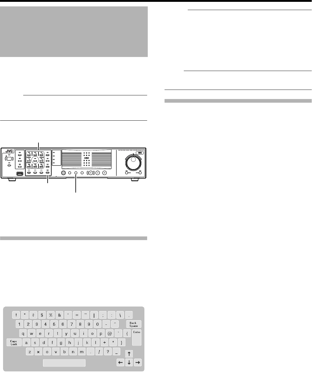
Character Input and Mouse Pointer ................................ 20
Entering Characters Using a Mouse ............................20
Controlling the Mouse Pointer Using the Front Panel
(When Mouse (Sold Separately) is not Connected)
.....20
Changing Monitor Resolution .......................................... 21
Precautions when Changing Settings .............................21
Basic Operation
Switching the Power On/Off ............................................ 22
Switching Operation On/Off ............................................22
Login ...............................................................................23
Opening the Main Menu ..................................................24
NVR Viewer ..................................................................... 25
Viewing Live Images via Front Panel Control .................. 26
Displaying the [Live] Screen ........................................26
Select a view ................................................................26
Select a Camera .......................................................... 26
Operating the Camera ................................................. 27
Viewing Live Images via Mouse Control ......................... 28
Displaying the [Live] Screen ........................................28
Select a view ................................................................28
Select a Camera .......................................................... 28
Viewing Images Using the PTZ Features ....................29
Using Preset Positions ................................................. 30
Other Useful Functions ................................................ 30
Playing Back Recorded Images
via Front Panel Control ..............................................32
Select a view ................................................................32
Searching Recorded Image
Using a Specific Date/Time .................................... 32
Playing, Skipping and Stopping Recorded Images ......32
Adjusting the Playback Speed
(Jog/Shuttle Playback) ........................................... 33
Playing Back Recorded Images via Mouse Control ........34
Select a view ................................................................35
Searching Recorded Image Using
[Time Navigation] ...................................................35
Searching Recorded Image
Using the Timeline Browser ...................................36
Searching Recorded Image Using Sequence ..............37
Searching Recorded Image from the Alert List ............37
Smart Search ...............................................................38
Playing, Skipping and Stopping Recorded Images ......39
Listening to Audio Sound .............................................40
Writing Images/Audio Sound to CDs and Other Media
(Export) ......................................................................41
Deleting Temporary Files
(Operation on the VR-N1600U/E Unit) ...................43
Deleting Data from a CD-RW
(Operation on the VR-N1600U/E Unit) ...................43
Writing Data to a USB Memory Device
(Operation on the VR-N1600U/E Unit) ...................44
Operation from a Surveillance Computer .....................44
Printing Recorded Images ...............................................45
Recording Camera Images .............................................46
Recording Modes .........................................................46
Recording Operation During Power Failure .................46
Selecting the Recording Control Mode ........................47
Selecting the Manual Recording Mode ........................47
Scheduler Setting .........................................................47
Specifying Image Recording Settings ..........................49
Settings ........................................................................50
Setting Picture Quality .................................................52
Specifying Audio Recording Settings ...........................53
Renaming Cameras and
Assigning Camera Numbers ..................................53
Screen Setup ...................................................................54
Screen Display (Groups and Views) ............................54
Creating Groups and Views .........................................54
Adding Cameras to a View ...........................................56
Adjusting Camera Settings ..........................................57
Using Your Views on Different Computers ...................57
Adding a Carousel .......................................................58
Adding Hot Spots (Enlarged Images) ..........................59
Using the [Html Page] ..................................................60
Using Still Images (GIF files, JPEG files, etc.) .............60
Adding Matrix Content .................................................60
Contents
VR-N1600_J.book Page 4 Wednesday, August 8, 2007 3:32 PM

5
Applications
Main Menu List ................................................................ 61
List of Menu Screens ...................................................61
Unit Setting .................................................................. 62
OS Setting ...................................................................64
Image Server Setting ...................................................66
Auto Detect Setting ......................................................70
Camera Record Setting ...............................................72
Adding Cameras .............................................................74
Editing Device Settings ...................................................75
PTZ Camera Settings (COM1/COM2) ............................76
Defining a Preset PTZ Position ....................................... 78
Stopping the Recording Server .................................... 78
Display the PTZ Preset Positions window .................... 78
Defining a Preset Position ............................................80
Moving to Preset Positions by Events .......................... 80
Auto PTZ Patrolling ......................................................81
Camera Input/Output Port and Events ............................ 83
I/O Settings .................................................................. 83
Input/Output Terminal on Rear Panel ...........................85
Specifying a VMD Event .............................................. 85
Specifying Timer Events .............................................. 85
Specifying an Output ................................................... 86
[Advanced] Screen .......................................................86
Configuring Event Buttons ........................................... 87
Specifying Generic Events ...........................................88
Event Notification Settings ...........................................90
Specifying an Output Port ............................................ 90
Camera Output Settings ..............................................91
Motion Settings ............................................................... 92
General Settings .............................................................93
E mail Settings .............................................................94
Archiving .........................................................................95
Database Settings ...........................................................96
Flash Memory Utility ........................................................98
Auto Detect Settings ......................................................100
Specifying IP Lease ...................................................100
Language Setting ..........................................................101
HDD Utility .....................................................................102
Restoring Default Settings ............................................103
Distribution Settings (Details) ........................................104
Connecting to a Computer ............................................106
Others
Compatible Equipment ..................................................112
Compatible Network Cameras ...................................112
Connecting a UPS .....................................................112
External Hard Disk Drives ..........................................112
Connecting an External Hard Disk Drive ...................112
NAS ............................................................................113
Special Key Operations .................................................113
Combining a Button with the [FUNCTION] Button
.........113
Pressing a Button for Two Seconds or Longer ...........113
Recording Before/After Occurrence
of Event or Motion ....................................................114
PTZ Camera Control .....................................................114
Display and Saving of Maintenance Information ...........116
Export Viewer ................................................................117
Customizing Joystick Settings .......................................119
Recording Time Schedule .............................................120
Default Value List ...........................................................122
Troubleshooting .............................................................126
Specifications ................................................................127
VR-N1600_J.book Page 5 Wednesday, August 8, 2007 3:32 PM

6
Getting Started
Locations of Storage and Use
䢇Do not store the unit at the following places.
Doing so may cause the unit to malfunction or break
down.
●Hot or cold places beyond the allowable operating
temperature (5 I to 40 I)
●Humid places beyond the allowable operating humidity
(30%RH to 80%RH) (no condensation)
●Places that emit a strong magnetic field, such as near
transformers and motors
●Places near devices that emit radio waves, such as
transceivers and mobile phones
●Places with considerable dust and sand
●Places with strong vibrations
●Places where water droplets may be formed, such as
window sides
●Places with considerable vapor and oil, such as
kitchens
●Places that emit radiation, X-rays, and corrosive gases
䢇Using this unit and the cable that is connected to it near
places where strong radio waves or magnetic fields (such
as near radios, TVs, transformers, and monitors) are
emitted may cause noises in the video images or color
changes.
Handling Precautions
䢇Do not stack the devices on one another during use.
Heat and noise from the devices may cause the unit to
malfunction or break down, and lead to fire.
䢇Do not block the ventilation holes.
Doing so may cause heat to trap inside the unit and result
in fire. Do not use this unit by laying it down sideways,
upside down, or at an angle.
䢇Do not place objects on this unit.
Placing heavy objects, such as TV monitors, or objects
that are bigger in size on this unit may cause it to lose
balance and drop or fall, hence resulting in injuries.
䢇Do not stand or sit on this unit.
Doing so may cause this unit to fall or break down, and
result in injuries. Keep it out of the reach of young
children.
䢇Do not place objects with water (e.g., vases, flower pots,
cups, cosmetic products, and chemicals) on this unit.
Water may enter this unit and result in fire or electric
shock.
䢇Do not insert objects into this unit.
Metallic or other flammable objects that enter this unit
from the ventilation holes may result in fire or electric
shock.
Precautions for Handling Hard Disk Drive
䢇The distance between the head and the disk is only about
0.02 μm when the hard disk (henceforth HDD) is reading
the data. Vibration or impact that is exerted on the HDD
may therefore cause the head to hit against the disk,
hence causing the disk surface to dent or the disk to chip.
When this occurs, data may not be properly read, or in a
worse scenario, continued use in this condition may result
in head crash (damage). Careful attention must therefore
be paid when handling it.
䢇Precautions During Installation and Change of Installation
Location
Moving of this unit or installation work is strictly prohibited
when the power of this unit is on or immediately after the
power is turned off (approximately 1 minute). (The HDD
continues to move under its own inertia for some time
after the power is disconnected, and exertion of vibration
or impact during this interval may result in HDD failure.)
When moving this unit, wrap it using cushioning materials
to protect it from external shock.
䢇Handling Precautions
●Handle this unit carefully without exerting vibration or
impact on it.
●Do not remove the power plug during recording or
playback, or when the HDD is being accessed.
●The HDD is a consumable product. Perform
maintenance after it has been used for about 10,000
hours (about 1 year). (This value is based on its use in
an environment with a temperature of 25 I, and may
vary according to the environment of use.) For inquiries
on maintenance plans and expenses, consult your
nearest JVC dealer listed on the separate sheet.
䢇When installing an external hard disk, we recommend the
use of UPS (uninterruptible power supply) to ensure the
stable operation of the system. [Connecting a UPS] (A
Page 112)
䢇Power failure that occurs during formatting or
disconnection of the HDD may affect its subsequent use
even when the UPS is connected.
䢇JVC shall not be held responsible for the compensation of
losses incurred in the event that recording or playback
fails due to defects in this unit or its hard disk drive.
●Images recorded on the HDD will be deleted when you
replace it with a new disk. Note also that recorded
images may be deleted when you upgrade the software
for this unit.
Precautions for Proper Use
of this Product
VR-N1600_J.book Page 6 Wednesday, August 8, 2007 3:32 PM
7
Precautions when Moving this Unit
䢇Remove all connected cords before moving
Turn off the power and remove the power plug before
moving this unit. Failure to do so may cause damage on
the cords, and result in fire or electric shock.
䢇Moving of this unit or installation work is strictly prohibited
when the power of this unit is on or immediately after the
power is turned off (approximately 1 minute).
The HDD continues to move under its own inertia for
some time after the power is disconnected, and exertion
of vibration or impact during this interval may result in
HDD failure.
䢇When moving this unit, wrap it using cushioning materials
to protect it from external shock.
䢇Handle this unit carefully without exerting vibration or
impact on it.
Precautions for Handling Power Cords
䢇Do not use the supplied cords on devices other than this
unit.
䢇Do not place heavy objects on the power cord, or place it
under this unit
Doing so may cause damage on the cords, and result in
fire or electric shock.
䢇Do not use cords other than those supplied with this unit
Use only power cords supplied together with this unit.
Using cords with different withstanding voltage
specifications or damaged cords may result in fire or
electric shock.
䢇Do not remove the power plug during recording or
playback, or when the HDD is being accessed.
Maintenance
䢇Turn off the power before performing maintenance of this
unit.
䢇Wipe this unit using a soft cloth. Wiping using thinner or
benzene may cause the surface to melt or fog. When the
surface is extremely dirty, wipe using a cloth that is dipped
into a neutral detergent diluted with water, followed by
wiping with a dry cloth.
Energy Conservation
䢇Turn off the power of the system for safety reasons and to
save energy if this unit is not to be used for a long time.
Copyright
䢇Use of video or audio sound recorded using this unit for
commercial purposes or playing them for public viewing or
listening may be an infringement of the copyrights of their
respective authors under the copyright law.
䢇These video (audio) recordings shall only be restricted to
personal uses, and their use without prior consent of the
copyright holder is strictly prohibited under the copyright
law.
Others
䢇When there is variation in the supply voltage such as
during lightning, operation of this unit may be disabled to
protect the system until the supply voltage stabilizes
again.
䢇Eliminate static electricity before performing work that
requires you to touch the input/output terminals, such as
when installing devices.
䢇Do not touch the rear panel of this unit when it is running
as static electricity may cause it to malfunction.
䢇When there is a large number of data recorded on this
unit, such as short alarm records, a longer time may be
required during search or backup. This is not a
malfunction.
䢇Data recorded from TV broadcasts or video (audio)
recordings shall only be restricted to personal uses, and
their use without the prior consent of the copyright holder
is strictly prohibited under the copyright law.
䢇The width of the border lines (black in color) of images on
the split screen varies according to the type of input
signals. This is due to the characteristics of the camera’s
input signals, and is not a malfunction. The condition may
also be improved by adjusting this unit. For details, consult
your nearest JVC dealer.
䢇This unit comes with a high-precision hard disk device. Be
careful not to exert vibration or impact on this unit when
handling it.
䢇Exertion of vibration or impact particularly when the power
is on or when the hard disk is being accessed may cause
this unit to break down.
䢇When moving this unit, do so about 1 minute after
disconnecting the power supply.
䢇Do not turn off the power switch at the rear of this unit or
unplug the power cord during recording or playback, or
when the hard disk is being accessed. Otherwise, it may
break down.
When this device is used as a general household,
there is a possibility of radio disturbance to the
radio and television receiver etc.
VR-N1600_J.book Page 7 Wednesday, August 8, 2007 3:32 PM
8
Getting Started
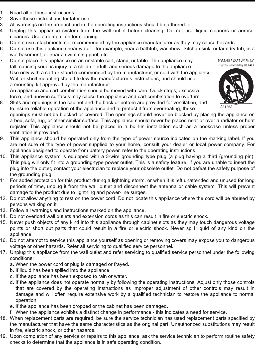
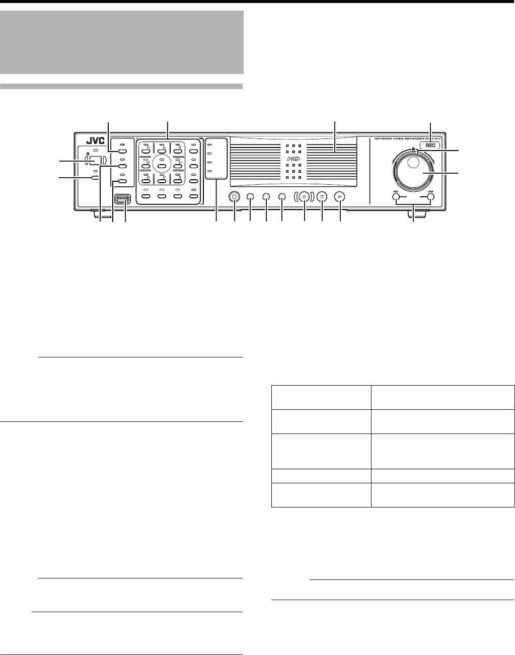
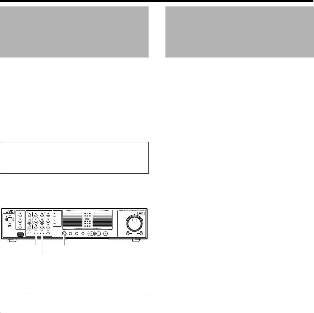
Front
A
[OPERATE] Button/Indicator
Switches operation on or off. Press the button to turn operation
A
ON
B
and hold down the button to turn operation
A
OFF
B
. The
indicator blinks while the recorder is starting up or shutting down.
B
[REC CONTROL] Button/Indicator
Switches the recording control mode on or off. The indicator lights
up when the recording control mode is set to on.
Press and hold the [FUNCTION] button, and press the [REC
CONTROL] button at the same time to display the menu.
Memo :
●
The main menu cannot be displayed in the recording control
mode or during recording.
●
The recording control mode performs recording in accordance
with the settings in the [Camera Record Setting] menu. (
A
Page
47)
C
[SELECT] Button/Indicator
Use the
S
key to set to the camera selection mode. The indicator
lights up when the camera selection mode is set to on. (
A
Page 28)
D
[PTZ/PRESET] Button/Indicator
Switches between the PTZ mode and PRESET mode of the
S
key.
The mode changes each time the button is pressed. The indicator
lights up when PTZ mode is selected and blinks when PRESET
mode is selected.
E
[SERIAL] Terminal
For connecting the communication control terminals on a mouse
(sold separately), flash memory (sold separately) or UPS (sold
separately).
Memo :
●
Use the [SERIAL1 to 4] port on the rear panel for additional hard
disk drive connection. (
A
Page 10)
Note :
●
Attach the serial port cover supplied when the port is not in use.
●
Static electricity may cause the unit to malfunction. Remove any
static electricity before starting operation.
F
Status indicators
䡵
[WARNING] Indicator
Lights up when an error occurs. (
A
Page 126)
Press and hold the [ALARM CLEAR] button to turn off the light.
䡵
[ALARM] Indicator
Lights up when an alarm is activated.
Goes off when the [ALARM CLEAR] button is pressed.
䡵
[HDD] Indicator
Lights up when the built-in hard disk drive is accessed.
䡵
[LOCK] Indicator
Lights up when operation is locked. (
A
Page 13)
G
[FUNCTION] Button
Press the following buttons while holding down the [FUNCTION]
button to use the following features.
[Special Key Operations] (
A
Page 113)
H
[SEARCH] Button
Displays the date and time search screen when in the playback
mode. (
A
Page 32)
I
[KEY] Button
Press to display or hide the
A
software keyboard
B
.
Memo :
●
Use the software keyboard to input characters. (
A
Page 20)
J
[ALARM CLEAR] Button
Clears the [ALARM] display when an event occurs or motion is
detected. Press and hold this button to turn off the [WARNING]
indicator.
K
[REC/STOP] Button
Press to start recording in all cameras. (When in the recording
control mode, pressing this button exits the recording control mode
and starts recording on all cameras.) To stop recording, press and
hold the button.
When in the recording control mode, press and hold this button to
exit the recording control mode.
Part Names and Functions
OPERATE
REC CONTROL
LIVE/BROWSE
SELECT
PTZ/PRESET
SERIAL
㧝 㧞 㧟 㧠
㧡 㧢*1/' 㧣
㧥
㧤
CANCEL ZOOM OUT ZOOM IN ENTER
WARNIN G
ALARM
HDD
LOCK
SEARCHFUNCTION ALARM CLEARKEY REC/STOP STOP(PB) PLAY
SKIP
REV FWD
A
T
B
G
FEDC I
HJK M
L
O
N
P
QRS
[FUNCTION]
+[OPERATE]
Press and hold to forcibly shut down
the system.
[FUNCTION] +[REC
CONTROL]
Displays the main menu.
[FUNCTION] +[LIVE/
BROWSE]
Reboots the NVR Viewer and the
internal distribution server.
Press and hold to log out.
[FUNCTION] +[5] For controlling the PTZ camera.
[FUNCTION] +[6] Displays the maintenance information
screen.
VR-N1600_J.book Page 8 Wednesday, August 8, 2007 3:32 PM

9
Memo :
●
The manual recording mode executes recording from all
cameras regardless of the settings in the [Camera Record
Setting]. Recording is carried out in accordance with the frame
rate selected in [Camera Record Setting]. (
A
Page 72)
L
[STOP(PB)] Button
Stops playback when you press this button in the playback mode.
M
[PLAY] Button
Plays back at the speed and in the direction specified by the Shuttle
Dial position.
N
[SKIP] Button
䡵
[
S
]
Press to move the item selection in the reverse direction in the
menu or settings screen. Jumps to the beginning of the previous
sequence on the selected camera when you press this button in the
playback mode. Press and hold it to jump to the first image in the
database of the selected camera.
䡵
[
T
]
Press to move the item selection in the forward direction in the
menu or settings screen. Jumps to the beginning of the next
sequence on the selected camera when you press this button in the
playback mode. Press and hold it to jump to the last image in the
database of the selected camera.
Memo :
●
“Sequence” indicates a certain block of images that are recorded
during motion detection.
●
Recorded images are stored in the database. “Database” refers
to data recorded in this unit.
O
Jog dial
Plays back a single frame when it is rotated in the playback mode.
P
Shuttle dial
The position of the dial specifies the playback speed and playback
direction when in the playback mode. Playback speed is selectable
from x 1/20, x 1/5, x 1, x 2, x 5, x 10 and x 20 according to the
angle.
Q
[REC] Indicator
Lights up during recording. Flashes during EMERGENCY or EXT
REC IN recording.
R
Center panel
Do not remove the cover.
S
Keypad buttons/Indicator
[0] to [16]
䢇
Login screen
●
For entry of passwords (numeric characters). (Enter number
using [1] to [10/0] buttons.
A
0
B
is input when [10/0] button is
pressed.)
䢇
Setting screens on the main menu
●
PTZ mode Keypad
For selecting a menu item. ([2/
D
], [10/0/
E
])
●
Camera selection keypad mode
For entering numeric characters. (Enter number using [1] to
[10/0] buttons.
A
0
B
is input when [10/0] button is pressed.)
䢇
Live image display and recorded image playback screens
●
Camera selection keypad mode
For selecting a camera number. Upon selecting, the indicator
corresponding to the selected camera input lights up.
●
PTZ keypad mode (live image display screen only)
Moves the camera in the direction indicated by the arrow. ([1/
][2/
D
] [3/ ][5/
C
][7/
B
] [9/ ][10/0/
E
] [11/ ])
Use the [6/HOME] button to move the camera to the home
position.
●
Preset keypad mode (live image display screen only)
For selecting the preset position. ([1] to [9]. 10 to 19 can be
selected when [10/0/
E
] is pressed at first.)
䢇
During search for recorded images
For narrowing down the search using a date, month, week, or
time.
(Enter number using [1] to [10/0] buttons.
A
0
B
is input when [10/
0] button is pressed.)
䢇
During display of software keyboard
●
Selection keypad mode
For entering numeric characters. (
A
0
B
is input when the [1/ ]
to [10/0/
E
] and [10/0/
E
] buttons are pressed.)
●
PTZ keypad mode (live image display screen only)
Moves the mouse pointer in the direction indicated by the
arrow. Press [1/ ][2/
D
] [3/ ][5/
C
][7/
B
] [9/ ][10/0/
E
] [11/ ] or
[6/HOME] to move to the center of the screen.)
[13/CANCEL]
䢇
Setting screens on the main menu
Cancels the selection.
[14/ZOOM OUT]
䢇
Live image display and recorded image playback screens
●
PTZ keypad mode (live image display screen only)
Zooms out.
●
Preset keypad mode
For selecting the next view.
●
Press the [14/ZOOM OUT] button while holding down the
[FUNCTION] button to change the resolution of VGA output.
[15/ZOOM IN]
䢇
Live image display and recorded image playback screens
●
PTZ keypad mode (live image display screen only)
Zooms in.
●
Preset keypad mode
For selecting the previous view.
●
Press the [15/ZOOM IN] button while holding down the
[FUNCTION] button to change the resolution of VGA output.
[16/ENTER]
䢇
Setting screens on the main menu
Confirms the selection.
䢇
During display of software keyboard
To perform the mouse click operation.
T
[LIVE/BROWSE] Button/Indicator
Switches between the [Live] mode and [Browse] mode.
The indicator lights up when in the [Live] mode.
Pressing the [LIVE/BROWSE] button when the wallpaper screen is
displayed shows the [Live] screen.
Press and hold the [FUNCTION] button, and press the [LIVE/
BROWSE] button at the same time to reboot the NVR Viewer and
the internal distribution server.
Press and hold the [FUNCTION] button, and press the [LIVE/
BROWSE] button at the same time to log out of the system.
Memo :
●When [Auto Logon] is enabled, the login operation starts
automatically immediately after logging out. (APage 62
[Unit Setting])
VR-N1600_J.book Page 9 Wednesday, August 8, 2007 3:32 PM
10
Getting Started
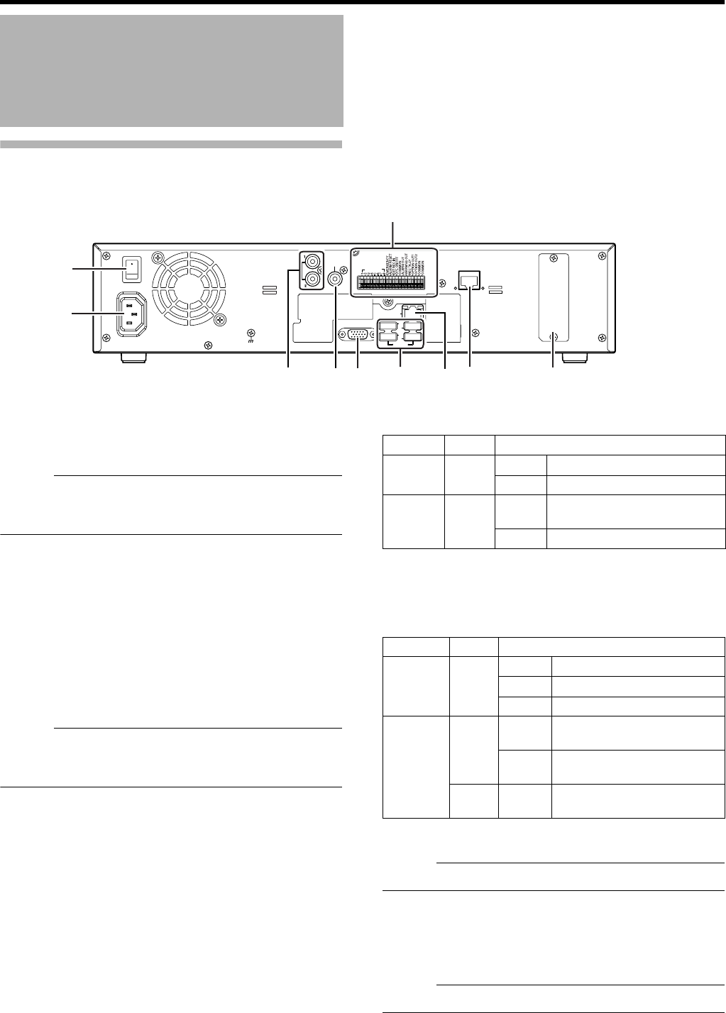
Rear Panel
U[POWER] switch
Switches the power on or off.
Memo :
●Be sure to press and hold down the [OPERATE] button on
the front panel to shut down the system before switching
off the power supply.
V
[AC IN] power input terminal
Connect to an AC outlet using the power cable supplied.
W
[AUDIO IN 1/AUDIO IN 2] audio input terminals 1/2
(RCA)
Connect to the audio output terminal of the device from
which audio signals are to be recorded.
X[AUDIO OUT] audio output terminal (RCA)
Outputs live sound in the live viewing mode.
Outputs recorded sound in the playback mode.
Memo :
●There is no audio output when playing back still images,
when running searches other than x1, or when playing
back frame-by-frame.
Y[VGA OUT] VGA output terminal
Outputs live images, recorded images and the menu
screens.
Z
[SERIAL1 to 4] serial terminals 1 to 4
For connecting the communication control terminals on a
mouse (sold separately), flash memory (sold separately),
UPS (sold separately) or additional disk drive (sold
separately).
a[LAN2] LAN2 connection terminal (Intranet)
For connecting to the remote PC network using a LAN cable.
b[LAN1] LAN1 connection terminal (camera
network)
For connecting to the IP camera (sold separately) network
using a LAN cable.
cConnector cover
Memo :
●Do not remove the cover.
dSignal input/output terminals
For operating VR-N1600U/E using external alarm signals or
signals received from external devices, or for operating
external devices by outputting signals.
Memo :
●Diameter of applicable cables: AWG22 to AWG28
Part Names and Functions
(continued)
ON
OFF
AUD IO IN
SIGNAL GND
AUD IO
OUT
VGA OU T
LAN1
SERIAL
1
2
3
4
LAN2
ALARM IN
POWER
U
V
Z
Y
X
Wc
b
d
a
Color Status
Left
Indicator
Green Light off Not connecting to the network.
Blinking Connecting to the network.
Right
Indicator
Green Light off Communication is not
established.
Blinking Communication is in progress.
Color Status
Left
Indicator
Orange
Light off Not connecting to the network.
Light on Connecting to the network.
Blinking Communication is in progress.
Right
Indicator
Green Light off Communication at 10 Mbit/
second.
Light on Communication at 100 Mbit/
second.
Orange
Blinking Communication at 1 Gbit/
second.
VR-N1600_J.book Page 10 Wednesday, August 8, 2007 3:32 PM
11
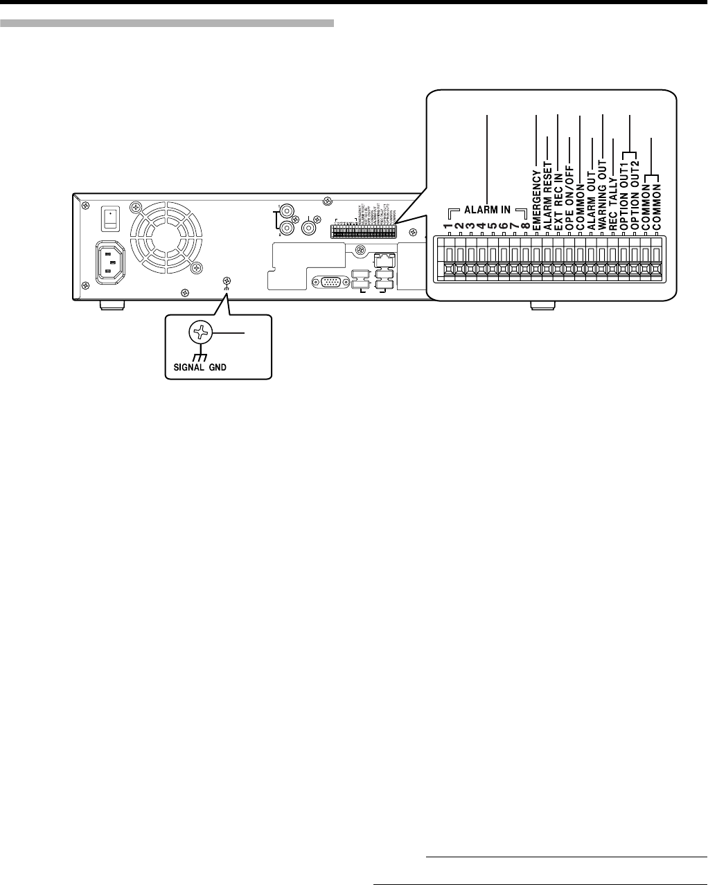
Rear I/O Terminals
䡵
Input ports
e[ALARM IN 1 to 8] alarm input terminals 1 to 8
Alarm recording is activated when signals are input to these
terminals.
f[EMERGENCY] emergency input terminal
Recording is activated in all cameras when a signal is input
to this terminal.
g[ALARM RESET] alarm reset input terminal
Output from the alarm output terminal is stopped when a
signal is input during output of the Alarm Out signals.
Turns off the [ALARM] indicator F on the main unit. Press
and hold the button to turn off the [WARNING] indicator F on
the main unit.
h[EXT REC IN] external recording input terminal
Recording in all cameras is started or stopped by an external
signal. Recording will not be started in cameras to which no
video signal is being input.
i[OPE ON/OFF] Operate ON/OFF terminal
Switches between OPERATE ON or OFF when a signal is
input. (A Page 22)
䡵
Output ports
j[COMMON] signal ground terminal
This is a common ground terminal. Connect it to the signal
ground terminal on the connected device. (This can be used
when there are insufficient common ground terminals.)
k[ALARM OUT] alarm output terminal
Outputs a signal when recording is started by an alarm.
l[WARNING OUT] warning output terminal
Outputs a signal when an error such as operation
abnormality occurs on the hard disk.
m[REC TALLY] recording status output terminal
Outputs the recording status of this unit.
n[OPTION OUT1][OPTION OUT2] OPT OUT
output terminals 1/2
Outputs a signal when an event is detected.
o[COMMON] signal ground terminal
Same as j.
p[SIGNAL GND] signal ground terminal
This is a common ground terminal. Connect it to the signal
ground terminal on the connected device.
(This can be used when there are insufficient common
ground terminals.
Memo :
●Do not use this terminal for protective earthing.
ON
OFF
AUDIO IN
SIGNAL GND
AUDIO
OUT
VGA OU T
LAN1
SERIAL
1
2
3
4
LAN2
ALARM IN
e
p
f
g
h
i
j
k
l
m
n
o
VR-N1600_J.book Page 11 Wednesday, August 8, 2007 3:32 PM
12
Getting Started
Rear I/O Terminals
Part Names and Functions
(continued)
Terminal Remarks
e[ALARM IN]
Memo :
●Set the impedance at the output end to 10kK or below.
Make Contact Input
f[EMERGENCY]
g[ALARM RESET]
Memo :
●Set the impedance at the output end to 10kK or below.
Make Contact Input
h[EXT REC IN]
Memo :
●Set the impedance at the output end to 10kK or below.
Make Contact Input
j[OPE ON/OFF]
Memo :
●Set the impedance at the output end to 10kK or below.
Make Contact Input
j[REC TALLY]
k[ALARM OUT]
l[WARNING OUT]
m[OPTION OUT1]
[OPTION OUT2]
(External Pull-up Level)
The make contact is formed using the individual output terminals and the
COM terminal. Turning off the power of VR-N1600U/E switches the
output of the output terminals to break.
Auto Collector Output
(DC15V, 10 mA and
below)
250 ms and
250 ms and
above
Make Break
250 ms and
250 ms and
1 s and above Approx.
50 ms
OPE ON OPE OFF
Make Output
In Progress
Break Output In
Progress
VR-N1600_J.book Page 12 Wednesday, August 8, 2007 3:32 PM
13
Use the supplied rack mount bracket to mount VR-N1600U/E
to the EIA rack.
1 Mount the rack mount bracket using screw (1)
●Use the 4 screws (M4 x 10 mm) supplied to fasten VR-
N1600U/E at the two sides.
2 Remove screws B of the foot (4 pcs) at the
bottom
●Remove the foot.
3 Mount to the rack using screws C
●Use the 4 screws (M5 x 11 mm) supplied to fasten this
unit to the rack.
Note :
●Do not place any object on the VR-N1600U/E unit that
has been mounted to the rack. Doing so may cause it to
lose balance and drop or fall, hence resulting in injuries or
damages.
●When mounting 2 or more units of VR-N1600U/E to the
rack, make sure to mount it at a distance that is at least
equivalent to one unit.
VR-N1600U/E
is equipped with an operation lock feature to
prevent the system from being turned off accidentally as well as
unauthorized recording operations.
Setting Operation Lock
1
Press and hold the [FUNCTION] button, and press the
[KEY] button at the same time
●Operation is locked. The [LOCK] indicator lights up
when in the operation lock mode.
Canceling Operation Lock
1 (When in the operation lock mode) Press the
[KEY] button while holding down the
[FUNCTION] button
●Operation lock is canceled.
●The light of the [LOCK] indicator goes off.
Mounting to a Rack
Rack Mount
Bracket
(4 Locations)
Operation Lock
OPERATE
REC CONTROL
LIVE/BROWSE
SELECT
PTZ/PRESET
SERIAL
㧝 㧞 㧟 㧠
㧡 㧢*1/' 㧣
㧥
㧤
CANCEL ZOOM OUT ZOOM IN ENTER
WARNING
ALARM
HDD
LOCK
SEARCHFUNCTION ALARM CLEARKEY REC/STOP STOP(PB) PLAY
SKIP
REV FWD
Keypad
[FUNCTION]
button
[KEY] Button
[LOCK] Indicator
VR-N1600_J.book Page 13 Wednesday, August 8, 2007 3:32 PM
14
Getting Started
Perform language setting and automatic camera registration
when starting up VR-N1600U/E for the first time.
Start up VR-N1600U/E
1 Turn on the power switch at the rear panel.
●VR-N1600U/E starts up.
Selecting a language
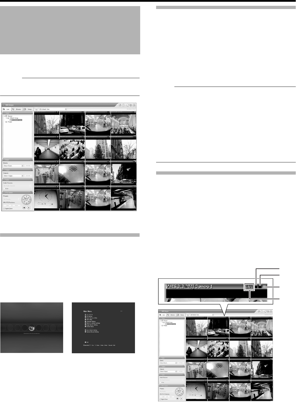
The [Language Setting] screen appears when you start up
VR-N1600U/E for the first time. Select the language to use
using the steps below.
1 Select a language
●Use the [2/D] or [10/0/E] button to select a language.
2 Use the [SKIP] button to select [OK], followed by
pressing the [16/ENTER] button
●The AThe system is being set up.B message may
appear depending on the setting, and the system is
automatically rebooted.
Memo :
●Selecting [OK] changes the color of the [OK] characters
from brown to orange.
Automatic Registration of Cameras
After you have started up VR-N1600U/E for the first time and
finished selecting a language, the [Auto Detect] screen
appears.
1 Check to ensure that [Auto Detect] is selected,
followed by pressing the [16/ENTER] button
●The APlease wait...B message appears.
Memo :
●The characters of the selected item switches to orange
color.
During Initial Startup
Before Starting Up.
●The DHCP setting is required for the IP camera
beforehand. Start up the VR-N1600U/E first, then switch
the camera on after confirming that the [Auto Detect
Setting] window is displayed.
●Refer to the user manual supplied with the camera for
instructions on how to specify the IP camera settings.
●By default, [Time Zone] is set to [(GMT-05:00) Eastern
Time](VR-N1600U)/[(GMT) Greenwich Mean Time](VR-
N1600E) and [Auto Summertime Adjustment] is
checked. Specify a Time zone according to the region
used. Refer to the INSTRUCTIONS on how to specify a
Time zone settings.
OPERATE
REC CONTROL
LIVE/BROWSE
SELECT
PTZ/PRESET
SERIAL
㧝 㧞 㧟 㧠
㧡 㧢*1/' 㧣
㧥
㧤
CANCEL ZOOM OUT ZOOM IN ENTER
WARNING
ALARM
HDD
LOCK
SEARCHFUNCTION ALARM CLEARKEY REC/STOP STOP(PB) PLAY
SKIP
REV FWD
Keypad
[SKIP]
Button
[KEY] Button
[16/ENTER]
Button
VR-N1600_J.book Page 14 Wednesday, August 8, 2007 3:32 PM
15
2 Check to ensure that the camera is detected
●After the message disappears, a list of detected
cameras is displayed.
●If all the cameras are not detected, press the [Auto
Detect] button again. If doing so does not solve the
problem, check the connection with the cameras and
the IP address of the cameras.
3 Swap the order of detected cameras
●Select SORT button using [SKIP] button and press
[16/ENTER] button. The order of detected cameras
can be sorted.
●The different types of sort buttons include the [IP],
[MAC], [CH], [MAKER], and [MODEL] sort buttons.
●Select list using [SKIP] button to select [2/D], [10/0/E].
After selecting camera, press [SKIP]] button to select
[Up], [Down]. When [16/ENTER] is pressed, the order
of cameras will be swapped.
●Deselect the check box of any camera that you are not
using.
Memo :
●The camera in the upper position of list order has the first
priority. Camera number will be registered in the list order.
4 Use the [SKIP] button to select [Entry], followed
by pressing the [16/ENTER] button
●The camera that is automatically detected is registered
in the system.
5 Use the [SKIP] button to select [OK], followed by
pressing the [16/ENTER] button
●The [Configure Device] screen appears.
6 Enter the password for the network camera
●Press the [KEY] button to display the software
keyboard. (A Page 20)
●Use the keypad to move the mouse cursor over the
software keyboard.
●Pressing the [16/ENTER] button inputs the characters
on the keyboard into the password field.
7 After password entry is complete, press [KEY]
again the close the software keyboard
8 Use the [SKIP] button to select [OK], followed by
pressing [16/ENTER]
9 Repeat the steps from 5 to 7 for every detected
camera
●The [Camera Record Setting] screen appears.
VR-N1600_J.book Page 15 Wednesday, August 8, 2007 3:32 PM
16
Getting Started
10 Set the display rate of each camera such that
the total display rate of all cameras does not
exceed 80 ips
●The default display rate is set to 8 ips. In other words,
the maximum display capacity of 80 ips will be
exceeded if 11 or more cameras are automatically
detected. In this case, you will need to follow the steps
below to adjust the display rate of each camera.
Note :
●The recording rate may drop if the total display rate of all
cameras exceeds 80 ips.
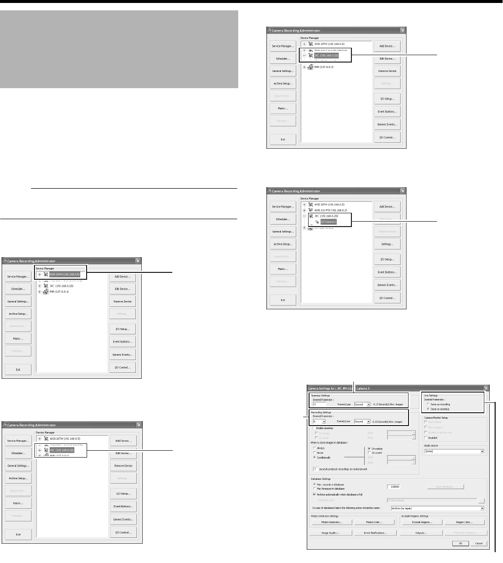
APress the [SKIP] to select the Device Manager
●The device at the top of the list is selected.
BUse the [2/D] and [10/0/E] buttons to select a device
CUse the [7/B] button to display the camera
DUse the [10/0/E] button to select a camera
EUse the [SKIP] button to select [Settings...], followed
by pressing the [16/ENTER] button
●The [Camera Settings] screen appears.
During Initial Startup
(continued)
A
B
C
D
Speedup Settings
Recording
Settings
Live Settings
VR-N1600_J.book Page 16 Wednesday, August 8, 2007 3:32 PM
17
FSetting the Live Image Display Rate
●Select ASame as recordingB or ASame sa speedupB
as the live image display rate in [Live Settings].
●When ASame sa speedupB is selected, the [Frame
Rate] specified in [Speedup Settings] is used as the
live image display rate.
●When ASame as recordingB is selected, the [Frame
Rate] specified in [Recording Settings] is used as the
live image display rate.
Memo :
●Use [SKIP] to move between the items.
●Use the [2/D] and [10/0/E] buttons to select the item to
configure.
●To enter numeric characters, press the [SELECT] button
to turn on the light of the [SELECT] indicator. Upon
entering the numeric characters, press the [PTZ/
PRESET] button to turn on the light of the [PTZ/PRESET]
indicator.
GUse the [SKIP] button to select [OK], followed by
pressing the [16/ENTER] button
11 Repeat the procedures 9 for each camera
12 Use the [SKIP] button to select [Close],
followed by pressing the [16/ENTER] button
●Setting is complete and the [Live] screen appears.
●The [REC CONTROL] indicator lights up and recording
starts in the recording control mode. (A Page 46)
[Live] Screen
VR-N1600_J.book Page 17 Wednesday, August 8, 2007 3:32 PM
18
Preparation
The following operations are possible with this system.
●Surveillance (live image, recording and playback) by connecting up to 16 cameras
●Checking recorded images on the VGA monitor
●Recording/Playing sound
●Alarm recording
●Remote surveillance using PCs
Memo :
●Connect LAN1 to the camera network.
●LAN2 to the surveillance computer network.
●For details of the protocol and port number for the network
cameras on the LAN1 network, refer to the network
camera’s user manual.
●The protocol and port number used on the LAN2 network
are shown below.
●Surveillance computer: HTTP 80
●Mail: SMTP 25/POP 110
●Connect NAS to the LAN1 network.
Note :
●Connect only after having turned AOFFB the power of all
devices.
●Set the IP address of the camera to 192.168.0.xxx. When
setting the IP address of the camera to an address other
than 192.168.0.xxx, you must also change the IP address
of LAN1. Refer to the [Instruction Manual] of each camera
for procedures to change the camera’s IP address,
System Connection
Example
ON
OFF
ACIN 100V H
AUDIOIN
SIGNALGND
AUDIO
OUT
VGA OUT
LAN1
SERIAL
1
2
3
4
LAN2
ALARM IN
AUDIO IN
AUDIO OUT
ALARM IN/ALARM OUT
VGA OUT
SERIAL
LAN1
LAN2
SERIAL
●You can connect up to 16 cameras.
●You can connect up to 10 surveillance
computers.
Speaker (with built-in amplifier)
ALARM IN/OUT
Supplied power cable
Mic Amp
VGA monitor
IP cameras
Computer for configuring
cameras
USB Mouse
Switching
HUB
Switching
HUB
UPS control
UPS
Microphone
Surveillance computer
NAS
VR-N1600_J.book Page 18 Wednesday, August 8, 2007 3:32 PM
19
Note :
●Do not connect LAN1 to the internet. If the internet is busy
or the relay equipment fails, you may not be able to save
important camera images. To maintain full recording
capacity, it is recommended that a dedicated network be
used. Be sure to connect the LAN1 camera network to the
same segment. (Do not use the address translation of
NAT and NAPT etc. or a router.)
●If you connect LAN2 to the internet from a surveillance
computer, you will need to configure IP Masquerading.
●Communication between LAN1 and LAN2 is not possible.
Nor is it possible to configure a camera connected to
LAN1 from the surveillance computer connected to LAN2.
In order to configure a camera connected to LAN1, it is
necessary to connect the computer for configuring
cameras to LAN1.
●LAN1 and LAN2 are incompatible with QoS. Sound may
not be played normally depending on the condition of the
circuit.
●The default LAN1 IP address is 192.168.0.253 and the
default LAN2 IP address is 192.168.1.253. To change the
address, use [OS Setting] (A Page 64).
●When a single network camera is registered with multiple
units of VR-N1600U/E, recording may not be properly
completed in some cases. Camera control (e.g. PTZ
control) may also become unstable. It is recommended
that a single VR-N1600U/E be used for registering one IP
camera as well as for controlling PTZ operations.
●Do not connect a broken hub, router or deteriorated
network cable etc. Doing so may prevent the system from
operating properly.
●Connection to a keyboard is not recommended.
VR-N1600U/E comes with a clock display feature.
You can display the current time on the screen.
1 Press and hold the [FUNCTION] button, and
press the [2/D] keypad button at the same time
●The clock is displayed at the top left corner of the
screen beside the performance meter.
Memo :
●To turn the clock display off, press the [2/D] keypad button
while holding down the [FUNCTION] button.
●To move the clock display position, left click and drag the
clock display to the desired position.
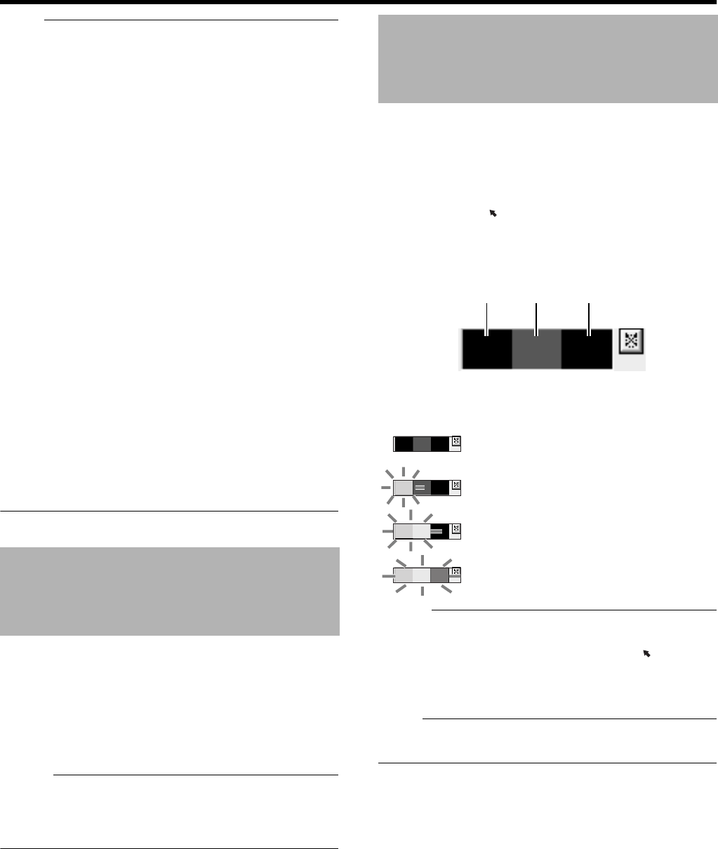
VR-N1600U/E comes with a performance meter, which
allows you to check the load of VR-N1600U/E on the meter.
At high operating loads, the system may not be able to
record at the preset frame rate or operate normally.
1 Press and hold the [FUNCTION] button, and
press the [1/ ] keypad button at the same
time
●The performance meter appears on the screen.
Memo :
●The performance meter automatically appears after VR-
N1600U/E starts up.
●To hide the performance meter, press the [1/ ] keypad
button while holding down the [FUNCTION] button.
●To move the display position of the performance meter,
left click and drag it to the desired position.
Note :
●Do not use the recorder when the performance meter is
indicated in red.
Clock Display
Performance Meter
Load factor of 5 % or less, indicated in gray
Load factor of 60 % or less, lights up in
green
Load factor of 90 % or less, lights up in
green and yellow
Load factor exceeds 90 %, lights up in
green, yellow and red
Green Yellow Red
VR-N1600_J.book Page 19 Wednesday, August 8, 2007 3:32 PM
20
Preparation
You can input characters and move the mouse pointers in
two different ways.
●Operate using the buttons on the front panel.
●Operate by connecting a mouse (sold separately).
Memo :
●Connecting a mouse eases the specification of complex
settings as well as input of characters.
●Connection to a keyboard is not recommended.
Entering Characters Using a Mouse
You can use the software keyboard to input characters when
you are using mouse.
1 Press the [KEY] button on the front panel
●The software keyboard appears.
●Press the [KEY] button again to hide the software
keyboard.
2 Move the mouse pointer over the character on
the software keyboard that you want to enter
3 Click on the character
Memo :
●You can move the software keyboard by dragging any
portion of the keyboard other than the keys with the
mouse.
●To drag the software keyboard from the front panel, press
the arrow buttons on the keypad while holding down the
[16/ENTER] button.
●You can move the mouse pointer using the keypad when
the software keyboard is displayed.
Note :
●The [16/ENTER] button is enabled with a click of a mouse
when the software keyboard is displayed.
Controlling the Mouse Pointer Using the Front
Panel (When Mouse (Sold Separately) is not
Connected)
When a mouse is not connected, you can control the mouse
pointer using the front panel.
1 Press the [KEY] button
●The software keyboard appears.
●Press the [KEY] button again to close the software
keyboard.
2 Move the mouse pointer with the keypad (arrow
key)
●Pressing the [16/ENTER] button has the same effect
as clicking at the position of the mouse pointer.
Character Input and Mouse
Pointer
OPERATE
REC CONTROL
LIVE/BROWSE
SELECT
PTZ/PRESET
SERIAL
㧝 㧞 㧟 㧠
㧡 㧢*1/' 㧣
㧥
㧤
CANCEL ZOOM OUT ZOOM IN ENTER
WARNING
ALARM
HDD
LOCK
SEARCHFUNCTION ALARM CLEARKEY REC/STOP STOP(PB) PLAY
SKIP
REV FWD
[16/ENTER] Button
[KEY] Button
Keypad
Software Keyboard
VR-N1600_J.book Page 20 Wednesday, August 8, 2007 3:32 PM
21
You can switch the resolution of the VGA output using the
following procedures.
●Press and hold the [FUNCTION] button, and press the
[14/ZOOM OUT] button at the same time.
hPressing the button each time increases the resolution
value.
●Press and hold the [FUNCTION] button, and press the
[15/ZOOM IN] button at the same time.
hPressing the button each time decreases the resolution
value.
Memo :
●Selecting a resolution not supported by the monitor may
prevent normal monitor synchronization.
Note that any incorrect changes made to the VR-N1600U/E
settings may prevent normal operation.
Before making any changes, save the current settings to
[Flash Memory Utility] (A Page 98) to allow you to restore
the previous settings should anything go wrong.
It is recommended that you save the setting data before
making any changes.
Changing Monitor
Resolution
Preset
Values
:1024 x 768 (Default value)
1280 x 768
1280 x 1024
1600 x 1200
OPERATE
REC CONTROL
LIVE/BROWSE
SELECT
PTZ/PRESET
SERIAL
㧝 㧞 㧟 㧠
㧡 㧢*1/' 㧣
㧥
㧤
CANCEL ZOOM OUT ZOOM IN ENTER
WARNING
ALARM
HDD
LOCK
SEARCHFUNCTION ALARM CLEARKEY REC/STOP STOP(PB) PLAY
SKIP
REV FWD
[15/ZOOM IN] Button
[FUNCTION] Button
[14/ZOOM OUT]
Button
Precautions when
Changing Settings
VR-N1600_J.book Page 21 Wednesday, August 8, 2007 3:32 PM

22
Basic Operation
Switching the Power On
1 Connect the power cable
●Connect the power cable to outlet.
2 Turn AONB the power switch at the rear panel.
●A system check will run when the power is turned on.
●The [OPERATE] indicator starts blinking.
●After blinking, the [OPERATE] indicator lights up to
indicate that operation has been turned on.
●When the setting is complete, recording starts
automatically in the record control mode. (When
[Record Control] under [Unit Setting] of the main menu
is set to AON at startupB.)
●
Note :
●Do not disconnect the power cord nor turn the power
switch AOFFB while the system check is running or in the
OPERATE ON mode. Otherwise, it may break down.
Switching the Power Off
1 Press and hold the [OPERATE] button for about
2 seconds to turn the operation off
●After blinking, the [OPERATE] indicator goes off.
2 Turn off the power switch on the rear panel
Note :
●The recorded images may not be played back properly if
they are not archived (A Page 97) before the power
failure.
●It is recommended that an uninterruptible power supply
(UPS) be used to protect the hard disk from damage in
the event of a power failure. (A Page 112)
Switching On/Off Using Operate Button on Front
Panel
You can switch operation to ON or OFF.
䡵
Switching Operation On
1 (When Operation is OFF) Press the [OPERATE]
button
●The [OPERATE] indicator starts blinking.
●The [OPERATE] indicator lights up, indicating that
operation is enabled.
Memo :
●When the power switch on the rear panel is turned on, the
system starts up automatically until the OPERATE ON
mode is activated.
䡵
Switching Operation Off
1 (When operation is ON) Press and hold the
[OPERATE] button for about 2 seconds
●The [OPERATE] indicator starts blinking.
●The screen display disappears and the [OPERATE]
indicator goes off, indicating that operation has been
turned off.
Note :
●Do not turn off the power until operation has been turned
off.
Switching On/Off Using Input/Output Terminal on
Rear Panel
For details on the layout of the input and output terminals on
the rear panel, refer to [Rear I/O Terminals] (A Page 11).
䡵
Switching Operation On
1 (When operation is OFF) Set the [OPE ON/OFF]
terminal to make for at least 50 ms
●The [OPERATE] indicator starts blinking.
●The [OPERATE] indicator lights up, indicating that
operation is enabled.
䡵
Switching Operation Off
1 (When operation is OFF) Set the [OPE ON/OFF]
terminal to make for at least 1 s
●The [OPERATE] indicator starts blinking.
●The screen display disappears and the [OPERATE]
indicator goes off, indicating that operation has been
turned off.
Note :
●Do not turn off the power until operation has been turned
off.
Switching the Power On/
Off
Switching Operation On/
Off
VR-N1600_J.book Page 22 Wednesday, August 8, 2007 3:32 PM
23
If [Auto Logon] is set to AoffB, the [Login] screen appears
after operation has been turned on. (Default setting: AonB)
Memo :
●You can specify the on/off setting of [Auto Logon] in [Unit
Setting] of the main menu. (A Page 62)
1 Enter the password using the keypad, and press
the [16/ENTER] button
●If login is successful, the wallpaper screen appears.
●When [Live viewing Auto Start] is set to AonB, the [Live]
screen appears when login is successful.
Memo :
●You can specify the setting of [Live viewing Auto Start] in
[Unit Setting] of the main menu. (A Page 62)
Note :
●Operation on the main unit is disabled if you do not log in.
●Warning messages (A Page 126) are not displayed when
you are not logged into the system. In this case, the
[WARNING] indicator lights up.
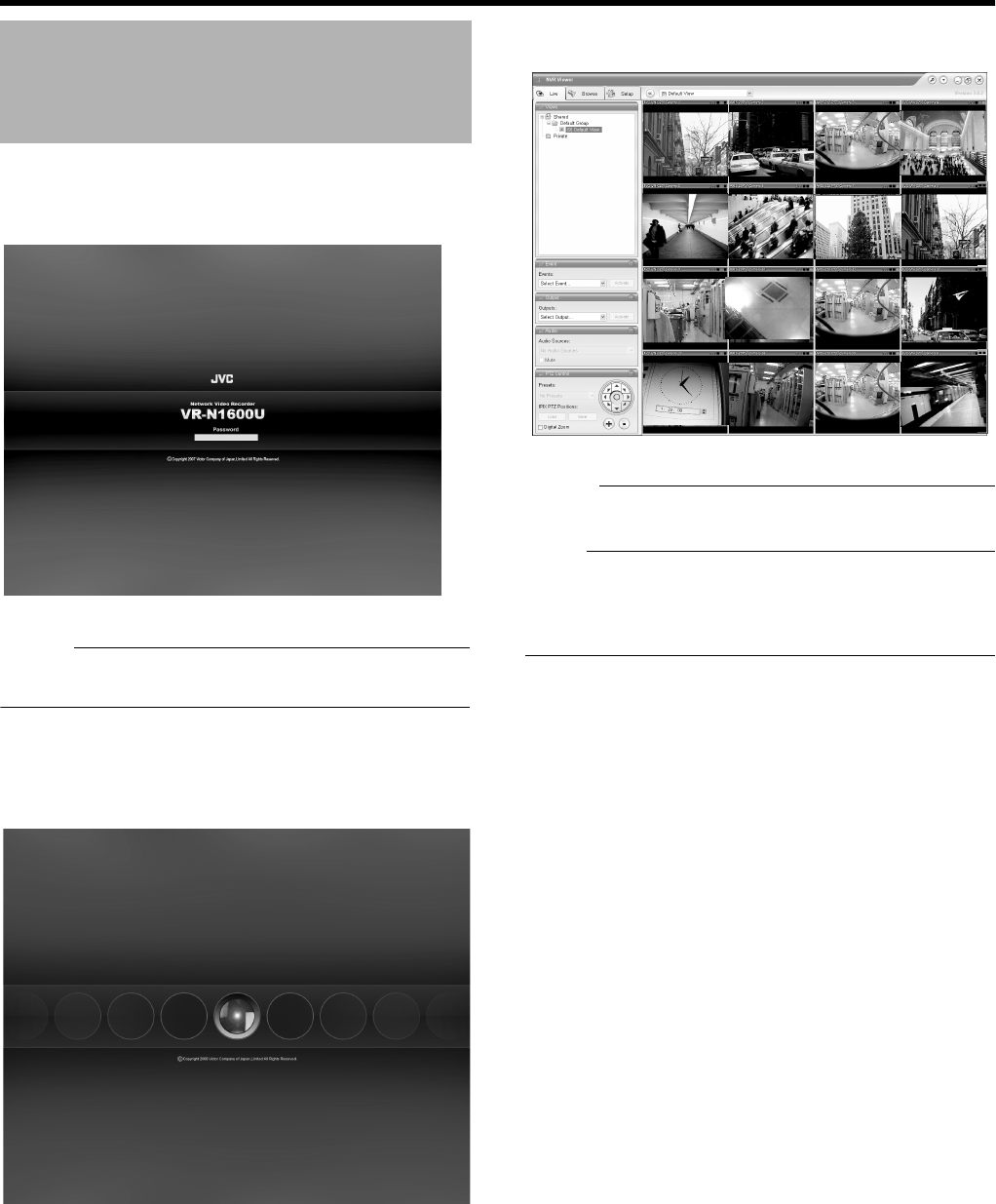
Login
Logon Screen
Wallpaper Screen
[Live] Screen
VR-N1600_J.book Page 23 Wednesday, August 8, 2007 3:32 PM
24
Basic Operation
The following are procedures to open the main menu, which
is used for specifying various settings.
1 Press and hold the [REC/STOP] button for at
least 2 seconds
●Recording stops.
Memo :
●When in the recording control mode, press and hold the
[REC CONTROL] button for at least 2 seconds to switch
the recording control mode off and stop recording.
●For details on the recording mode, refer to [Recording
Modes] (A Page 46).
2 Press and hold the [FUNCTION] button, and
press the [REC CONTROL] button at the same
time
●The main menu appears.
●Select a menu with the [2/D] or [10/0/E] button and
press the [16/ENTER] button to open the selected
setting screen.
●The same operation can be done using the [SKIP]
button.
3 Select an item
●Select the required item using the [2/D] or [10/0/E]
button and specify the settings.
●Press the [16/ENTER] button to save the settings, and
press the [13/CANCEL] button to close the screen and
return to the main menu.
Memo :
●To exit the main menu, press the [13/CANCEL] button.
Note :
●In some occasions, the NVR Viewer may appear instead
when you try to display the main menu while the NVR
Viewer is running. In this case, press the [LIVE/BROWSE]
button on the front panel and perform the operation to
display the main menu again.
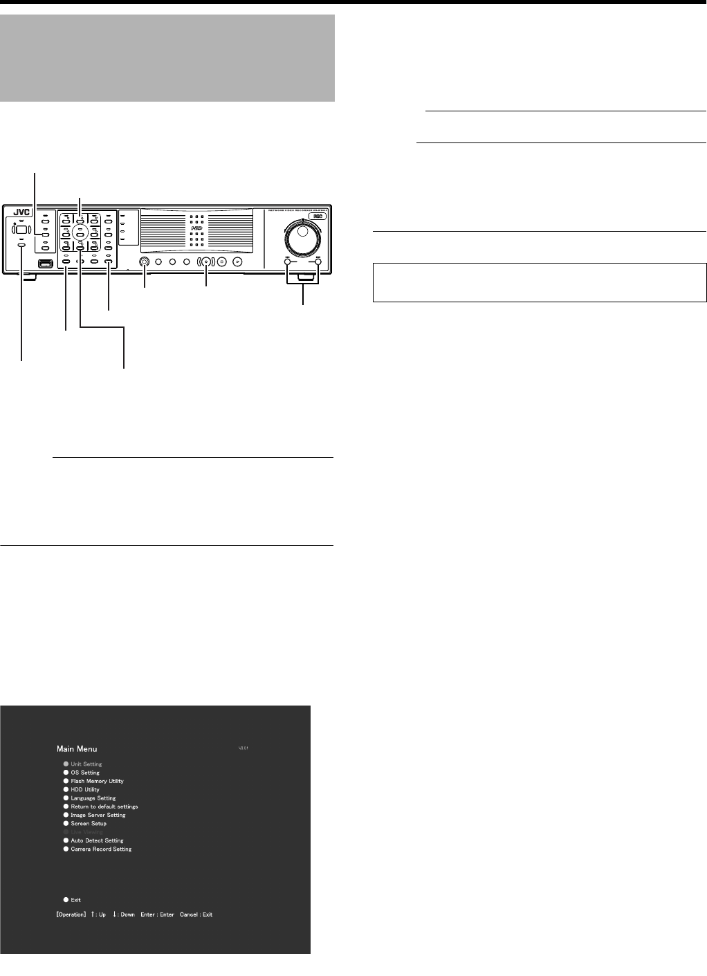
Opening the Main Menu
OPERATE
REC CONTROL
LIVE/BROWSE
SELECT
PTZ/PRESET
SERIAL
㧝 㧞 㧟 㧠
㧡 㧢*1/' 㧣
㧥
㧤
CANCEL ZOOM OUT ZOOM IN ENTER
WARNING
ALARM
HDD
LOCK
SEARCHFUNCTION ALARM CLEARKEY REC/STOP STOP(PB) PLAY
SKIP
REV FWD
[13/CANCEL]
Button
[16/ENTER] Button
[REC CONTROL]
Button
[REC/STOP] Button
[FUNCTION]
Button
[2/D] Button
[10/0/E] Button
[SELECT] Button
[SKIP] Button
Main Menu
䢇For details on the main menu settings, refer to
[Main Menu List] (A Page 61).
VR-N1600_J.book Page 24 Wednesday, August 8, 2007 3:32 PM
25
●You can view live and recorded images using the NVR Viewer.
●NVR Viewer can also be used for remote surveillance of VR-N1600U/E from a PC. (A Page 111)
●Some of the NVR Viewer features may vary during remote surveillance from a PC.
Memo :
●NVR Viewer operates by logging into the distribution
server inside VR-N1600U/E.
●Built-in NVR Viewer logs into the distribution server of VR-
N1600U/E (http://localhost or http://127.0.0.1). By default,
[Auto Login] to VR-N1600U/E is set to [On]. For details on
the login procedures, refer to [Connecting to a Computer]
(A Page 106).
●The NVR Viewer is unable to log in when the maximum
number of clients are connected to the surveillance
computer.
Note :
●When you have changed the settings in the [Camera
Record Setting] of the main menu, log out of the NVR
Viewer, and log in again. (A Page 111)
●When in the default state, you can click the [Connect]
button on the [Connect to Server] screen to log in. When
settings are changed, refer to the description after Step 2
of eLogin to the NVR Viewerf (A Page 110).
●When the following symptoms appear, recovery may be
possible by restarting the NVR Viewer.
●Live video and playback images appear in black.
●NVR Viewer action is slow.
●NVR Viewer does not respond.
Note :
●To restart the NVR Viewer, press and hold the
[FUNCTION] button, and press the [LIVE/BROWSE]
button at the same time. The internal distribution server of
VR-N1600U/E is also rebooted in this case.
●The image and sound may not properly synchronize
during playback on the NVR Viewer.
●After you have completed the e-mail setting, perform a
test to verify that it can be sent successfully. (A Page 94)
●When an external hard disk is connected, it may take
several minutes to start up.
●Do not start up the NVR Viewer during recording at 240
ips. Doing so may cause the recording frame rate to drop.
NVR Viewer
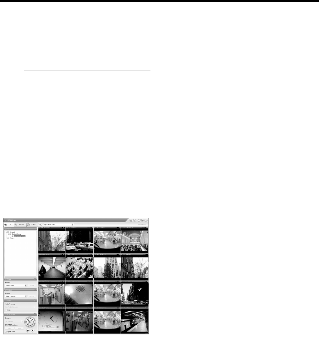
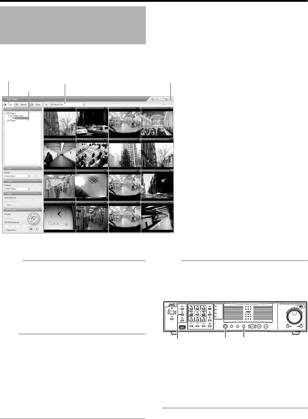
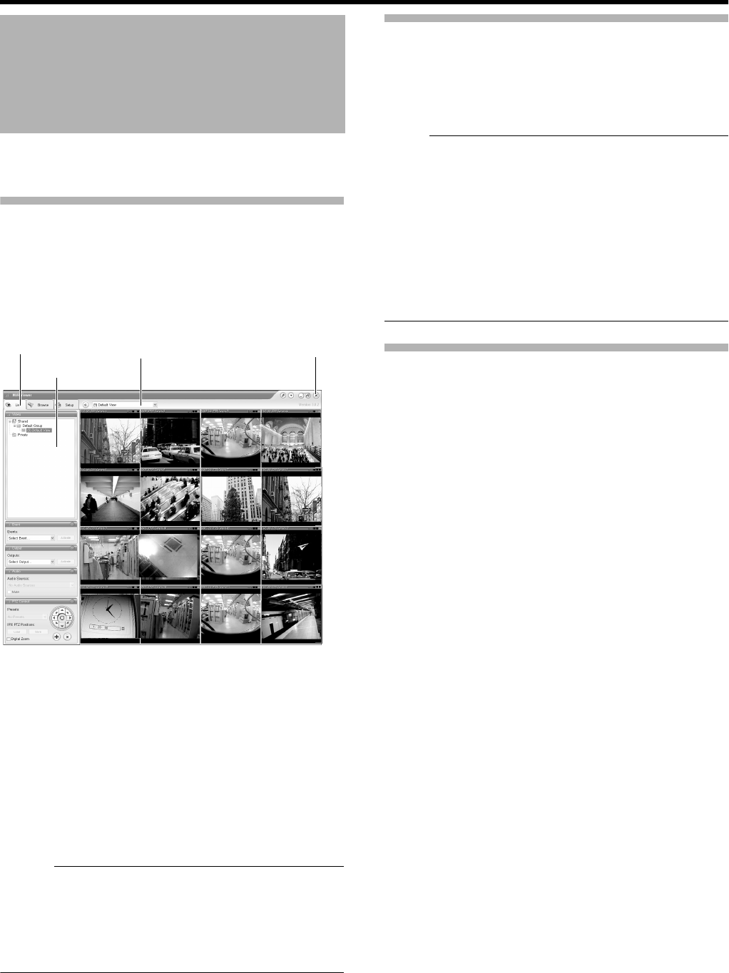
NVR Viewer[Live] Screen
View List
[Views] Section
[Live] Tab [⳯] Button
OPERATE
REC CONTROL
LIVE/BROWSE
SELECT
PTZ/PRESET
SERIAL
㧝 㧞 㧟 㧠
㧡 㧢*1/' 㧣
㧥
㧤
CANCEL ZOOM OUT ZOOM IN ENTER
WARNING
ALARM
HDD
LOCK
SEARCHFUNCTION ALARM CLEARKEY REC/STOP STOP(PB) PLAY
SKIP
REV FWD
[SELECT] Button [ALARM CLEAR]
Button
[FUNCTION]
Button
VR-N1600_J.book Page 25 Wednesday, August 8, 2007 3:32 PM
26
Basic Operation
This section describes the procedures for viewing live
images by using the front panel of VR-N1600U/E.
Memo :
●To operate by connecting a mouse (sold separately), refer
to [Viewing Live Images via Mouse Control] (A Page 28).
Displaying the [Live] Screen
1 Press the [LIVE/BROWSE] button when the
wallpaper *1 or main menu *2 screen is
displayed.
●Press the [LIVE/BROWSE] button when the [Browse]
screen is displayed.
●Press the button to toggle between the [Live] and
[Browse] screens.
Select a view
For details on the view settings, refer to [Screen Setup] (A
Page 54).
1 Press the [PTZ/PRESET] button to switch the
[PTZ/PRESET] indicator to the blinking mode
●Press the [PTZ/PRESET] button to switch the [PTZ/
PRESET] indicator between the lit and blinking modes.
2 Press the [15/ZOOM IN] and [14/ZOOM OUT]
buttons to select a view
Note :
●Do not switch the view frequently within a short time
interval.
●When live images do not appear on VN-C625/VN-C655,
set the password on the camera unit as well as VR-
N1600U/E again. For details on the setting procedures,
refer to the [INSTRUCRTIONS] of the camera in use and
procedures for setting the root password on the [Edit
device settings] screen in this manual (A Page 75).
●The audio setting is set to ANo Audio SourcesB when you
return from the setting screen to [Live]. Select the audio
parameters again.
Select a Camera
Select the camera image that you want to view as follows.
1 Press the [SELECT] button
●The [SELECT] indicator lights up.
2 Enter the camera number using the [1] to [16]
keypad
●When you have selected a camera, the blue bar at the
top of each live image changes to a lighter blue tone.
●Each bar comes with a tri-color square indicator, which
indicates the following features, as well as characters
that indicate the operating status of the camera.
Viewing Live Images via
Front Panel Control
[Live] Screen
*1 Wallpaper Screen *2 Main Menu Screen
A
B
C
D
[Live] Screen
VR-N1600_J.book Page 26 Wednesday, August 8, 2007 3:32 PM
27
Memo :
AEvent indicator (Left: yellow)
Lights up when events specified in the [Camera Record
Setting] occur. The indicator appears black if event
indication has not been specified for the camera in
question, or if no specified event has occurred.
BMotion indicator (Center: red)
Lights up when motion is detected.
COnline indicator (Right: green)
Blinks every time an image is received from the camera.
DOperating status of the camera (Appears to the left of
the indicator)
●You can press the [ALARM CLEAR] button to hide the
event indicator and motion indicator.
●The image bar displays the name of the camera as well as
the name of the device to which the camera is connected.
●Pressing a number that corresponds to the selected
camera enlarges the display. To restore display to the
normal size, press the number of the camera with
enlarged display.
Operating the Camera
PTZ stands for pan, tilt and zoom.
If the camera supports the PTZ functions, you can use the
keypad, and the [16/ENTER] and [13/CANCEL] buttons to
move the camera up/down (tilt), left/right (pan), or enlarge/
reduce the image (zoom).
䡵Pan/Tilt
1 Press the [PTZ/PRESET] button to switch the
keypad to the PTZ mode
●The [PTZ/PRESET] indicator lights up.
●Press the button to switch between the APTZ ModeB
(indicator lights up) and APreset ModeB (indicator
blinking).
2 Press the 1 to 9 keypad
●Pans/Tilts in the direction indicated by the arrow on the
keys.
●Press the [6/HOME] key to move to the home position.
䡵
Zoom In/Zoom Out
1 Press the [PTZ/PRESET] button to switch the
keypad to the PTZ mode
●The [PTZ/PRESET] indicator lights up.
●Press the button to switch between the APTZ ModeB
(indicator lights up) and APreset ModeB (indicator
blinking).
2 Press the [15/ZOOM IN] or [14/ZOOM OUT]
button
䡵Using Preset Positions
1 Press the [PTZ/PRESET] button to switch the
keypad to the Preset mode
●The [PTZ/PRESET] indicator starts blinking.
●Press the button to switch between the APTZ ModeB
(indicator lights up) and APreset ModeB (indicator
blinking).
2 Enter the preset number using the [1] to [10/0]
keypad
●The camera moves to the preset position.
Memo :
●You can specify numbers from 10 to 19 by pressing [10/0]
followed by a number from [10/0] to [9].
Note :
●You need to specify the preset positions in advance in
order to use the preset feature.
Display Status
Live (Green) When live images are displayed
without being recorded
Recording
(Red)
When recording is in progress
Stop (Yellow) When images are not acquired from
the camera, or when the camera is in
the offline mode (A Page 47)
OPERATE
REC CONTROL
LIVE/BROWSE
SELECT
PTZ/PRESET
SERIAL
㧝 㧞 㧟 㧠
㧡 㧢*1/' 㧣
㧥
㧤
CANCEL ZOOM OUT ZOOM IN ENTER
WARNING
ALARM
HDD
LOCK
SEARCHFUNCTION ALARM CLEARKEY REC/STOP STOP(PB) PLAY
SKIP
REV FWD
[14/ZOOM OUT] Button
[15/ZOOM IN] Button
[REC CONTROL]
Button
[ALARM CLEAR] Button
[FUNCTION]
Button
Keypad
[PTZ/PRESET] Button
[SELECT] Button
[LIVE/BROWSE] Button
VR-N1600_J.book Page 27 Wednesday, August 8, 2007 3:32 PM
28
Basic Operation
This section describes the procedures for viewing live
images by controlling the mouse.
Displaying the [Live] Screen
1 Select [Live] from the main menu
●The NVR Viewer starts up and the [Live] screen
appears.
●When the [Browse] or [Screen Setup] screen of the
NVR Viewer is displayed, click the [Live] tab.
●To exit the NVR Viewer, click the [⳯] button.
●If you have specified the camera record settings without
closing the [Live] screen, live images may not appear
immediately after you have exited the camera settings.
In this case, AUnable to connect to the server!
Reconnecting to the serverB or AUnable to connect to
127.0.0.1:80 on the device name(camera name)!
Reconnecting to the serverB will appear on the [Live]
screen. (127.0.0.1:80 is the internal IP address of the VR-
N1600U/E that is currently in operation.)
Memo :
●Depending on the condition of the network circuit, it may
take some time before images from the camera are
displayed.
●Depending on the connection of the additional hard disk,
several minutes may be required for the [Live] screen to
appear.
Select a view
For details on the view settings, refer to [Screen Setup] (A
Page 54).
1 Select a view from the [Views] section, or from
the view list at the upper end of the window
Note :
●Do not switch the view frequently within a short time
interval.
●When live images do not appear on VN-C625/VN-C655,
set the password on the camera unit as well as VR-
N1600U/E again. For details on the setting procedures,
refer to the [INSTRUCRTIONS] of the camera in use and
procedures for setting the root password on the [Edit
device settings] screen in this manual (A Page 75).
●The audio setting is set to ANo Audio SourcesB when you
return from the setting screen to [Live]. Select the audio
parameters again.
Select a Camera
1 Select a camera by clicking on the bar at the
upper end of the screen of the camera to select
using the mouse
●When you have selected a camera, the blue bar at the
top of each live image changes to a lighter blue tone.
Viewing Live Images via
Mouse Control
[Live] Screen
View List
[Views] Section
[Live] Tab [⳯] Button
VR-N1600_J.book Page 28 Wednesday, August 8, 2007 3:32 PM
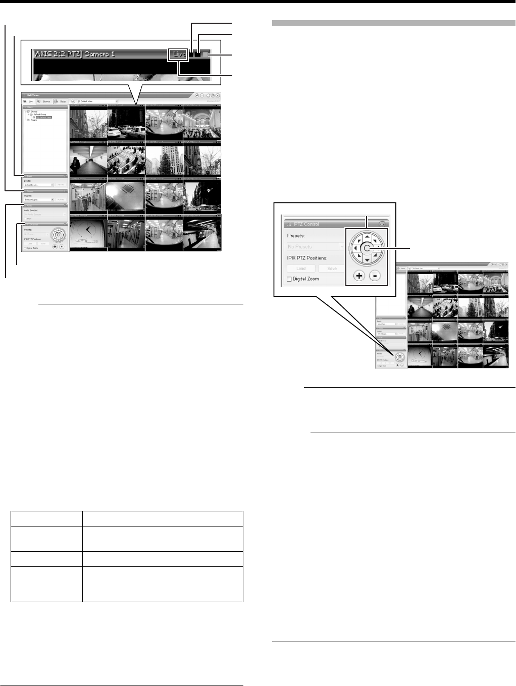
29
Memo :
●When you have selected a camera, the blue bar at the top
of each live image changes to a lighter blue tone. This bar
comes with a tri-color square indicator, which indicates
the following features, as well as characters that indicate
the operating status of the camera.
AEvent indicator (Left: yellow)
Lights up when events specified in the [Camera Record
Setting] occur. The indicator appears black if event
indication has not been specified for the camera in
question, or if no specified event has occurred.
BMotion indicator (Center: red)
Lights up when motion is detected.
COnline indicator (Right indicator: Green)
Blinks every time an image is received from the camera.
DOperating status of the camera (Appears to the left of
the indicator)
●The image bar displays the name of the camera as well as
the name of the device to which the camera is connected.
●To enlarge the camera image, double-click the blue bar at
the top. To return to the original size, double-click the blue
bar again.
●You can turn off the light of the indicator by clicking the
event or motion indicator that is lit.
Viewing Images Using the PTZ Features
PTZ stands for pan, tilt and zoom.
The PTZ features are only available if the camera supports
the PTZ functions. If the camera is not a PTZ camera,
pressing the button will have no effect.
1 Click the PTZ navigation button in the [PTZ
Control] section
●The camera moves in the direction indicated by the
arrow.
●Click the round button at the center to return to the
home position.
●Click the [+] and [-] buttons to zoom in and out
respectively.
Note :
●The PTZ features are only available if the camera
supports the PTZ functions. If the camera is not a PTZ
camera, pressing the button will have no effect.
Memo :
●If you see a set of crosshairs when placing your mouse
pointer over the image from a PTZ camera, then you are
able to control the orientation of the camera using point-
and-click control on the image screen. Control of the
camera on the image screen is not possible if the mouse
pointer does not change to the cross shape pointer. The
mouse pointer may not change to the cross-shape pointer
depending on the type of the PTZ camera. Control of the
PTZ camera may not be possible for some PTZ cameras
even though the mouse pointer changes to the cross-
shape pointer. In this case, use the PTZ navigation button
of the [PTZ Control] section to control the PTZ camera.
●The mouse pointer does not change to the cross shape
pointer for analog cameras that are connected to a
network encoder (IP video server), such as VN-E4.
●If your mouse is equipped with a scroll wheel, you can use
it to control the zoom in/zoom out function on the PTZ
camera.
Display Status
Live (Green) When live images are displayed
without being recorded
REC (Red) When recording is in progress
Stop (Yellow) When images are not acquired from
the camera, or when the camera is in
the offline mode (A Page 47)
A
B
C
D
[Event] Section
[PTZ Control] Section
[Outputs...] Section
[Audio] Section
[Live] Screen
PTZ Navigation Button
[Live] Screen
Home Button
VR-N1600_J.book Page 29 Wednesday, August 8, 2007 3:32 PM
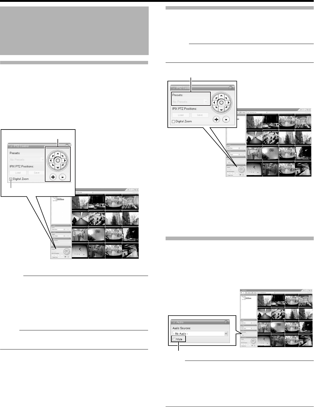
30
Basic Operation
Viewing Images Using the PTZ Features
(continued)
䡵
Digital Zoom
By selecting the [Digital Zoom] check box in the [PTZ
Control] section, you are able to use digital zoom on images
from any camera displayed in the view. When digital zoom is
enabled, you will see a small overview frame at the bottom
right corner.
Memo :
●The recorded images will not be recorded in zoom even
when digital zoom is used.
●When digital zoom is used, the recording frame rate may
decrease due to an increase in the load factor of VR-
N1600U/E.
●To exit the digital zoom function, deselect the [Digital
Zoom] check box.
Note :
●When the [Digital Zoom] check box is selected, the actual
PTZ operation will not be performed.
Using Preset Positions
Making a selection from the preset list enables you to move
the orientation of the camera to a preset position. (APage
80 [Defining a Preset Position])
Memo :
●The buttons are only available if the camera is a PTZ
camera.
1 Click the [K] button on the [Presets] list in the
[PTZ Control] section
●The preset list appears on the screen.
2 Select a preset position from the preset list
●The camera moves to the preset position.
Other Useful Functions
䡵
Listening to Audio Sound
To listen to live audio sound, select the required audio source
from the [Audio Source] list of the [Audio] section.
To temporarily mute the live audio sound, select the [Mute]
check box.
Note :
●When the audio source is selected by multiple
surveillance computers, the sound quality may
deteriorate.
●The audio setting is set to ANo Audio SourcesB when you
return from the setting screen to [Live]. Select the audio
parameters again.
Viewing Live Images via
Mouse Control (continued)
PTZ Navigation Button
[Live] Screen
[Digital Zoom]
[Presets] List
[Live] Screen
Select check
VR-N1600_J.book Page 30 Wednesday, August 8, 2007 3:32 PM
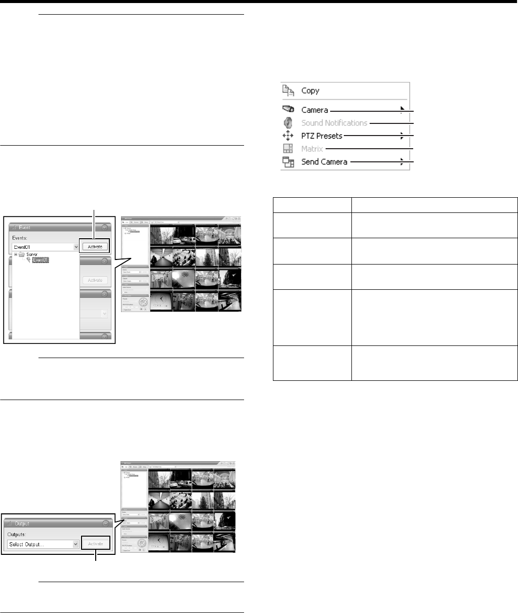
31
Memo :
●If you have selected a camera for which an audio source
has been set on the [Camera Settings] screen of [Camera
Record Setting], the preset audio sound is being output.
(A Page 49)
●If you have selected a camera for which an audio source
has not been specified, the most recently selected audio
source will be continuously output.
●When the recorded and live images are simultaneously
displayed, the displayed video image and audio sound
may not synchronize properly. (However, this has no
impact on recording to the system or additional hard disk.)
䡵
Manually Triggering an Event
To manually trigger an event, select the event in the [Event]
section, and click the [Activate] button.
Memo :
●For details on events, refer to [Camera Input/Output Port
and Events] (A Page 83).
●Events must be defined in advance. (A Page 83)
䡵
Triggering Outputs
To trigger an output, select the output in the [Outputs...]
section, and click the [Activate] button.
Memo :
●Outputs must be defined in advance. (APage 86
[Specifying an Output])
䡵
Camera Shortcut Menus
You can right-click on one of the images from the camera to
access the shortcut menu.
Items in the shortcut menu may vary according to the
configuration of the selected camera.
[Live] Screen
Click
[Live] Screen
Click
Item Description
ACamera Displays the video image of another
camera in the selected position.
BSound
Notifications
Temporarily mutes warning sounds.
CPTZ Presets Moves the camera to the preset
position you have selected.
DMatrix Select this option to use the Milestone
XProtect Matrix feature. For details,
refer to the Milestone XProtect Matrix
manual provided by Milestone
Systems.
ESend
Camera
Sends images from the selected
camera to another single-camera
position in an open view.
A
B
C
D
E
VR-N1600_J.book Page 31 Wednesday, August 8, 2007 3:32 PM
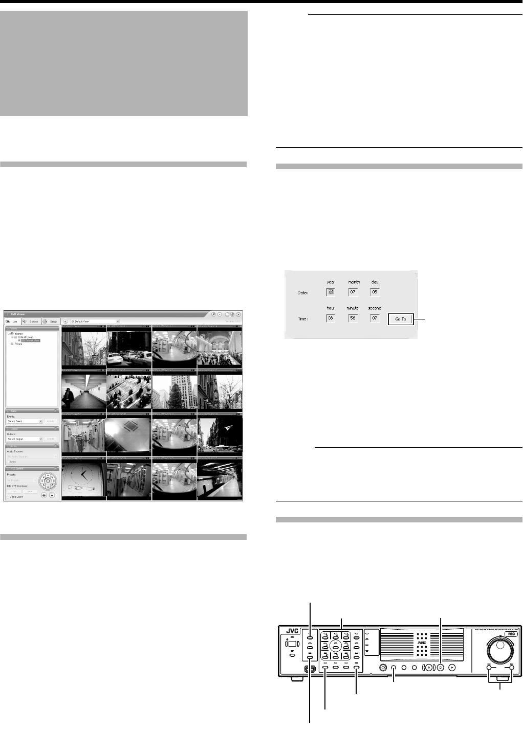
32
Basic Operation
This section describes the procedures for playing back
recorded images using the front panel of VR-N1600U/E.
Displaying the [Browse] Screen
1 Press the [LIVE/BROWSE] button when the
wallpaper or main menu screen is displayed
●The NVR Viewer starts up and the [Live] screen
appears.
2 When the [Live] screen appears, press the
[LIVE/BROWSE] button again
●Press the button to toggle between the [Live] and
[Browse] screens.
Select a view
For details on the view settings, refer to [Screen Setup] (A
Page 54).
1 Press the [PTZ/PRESET] button until the [PTZ/
PRESET] indicator blinks.
●The [PTZ/PRESET] indicator switches between lit and
blinking each time the [PTZ/PRESET] button is
pressed.
2 Press the [15/ZOOM IN] or [14/ZOOM OUT]
button to select a view
Note :
●Do not switch the view frequently within a short time
interval.
●When live images do not appear on VN-C625/VN-C655,
set the password on the camera unit as well as VR-
N1600U/E again. For details on the setting procedures,
refer to the [INSTRUCRTIONS] of the camera in use and
procedures for setting the root password on the [Edit
device settings] screen in this manual (A Page 75).
●The setting in the [Audio] section is set to ANo Audio
SourcesB when you return from the setting screen to
[Browse]. Select the audio parameters again.
Searching Recorded Image Using a Specific Date/
Time
You can search for and play back images by specifying a
date and time using the [SEARCH] button on the front panel.
1 Press the [SEARCH] button on the [Browse]
screen
●The date and time input screen appears.
2 Use the keypad to enter the search date and
time
●Use the [SKIP] button (S or T) to select an item
and input accordingly.
3 Press the [16/ENTER] button
●The view in the image display screen on the right
jumps to the selected date and time.
Memo :
●
You can also jump to the selected date/time by clicking the
[Go To] button.
●When you are using the software keyboard, click the [Go
To] button.
Playing, Skipping and Stopping Recorded Images
Control using the [PLAY], [SKIP], and [Stop] buttons.
䡵
Control using the [PLAY], [SKIP], and [PLAY] buttons
on the front panel
Playing Back Recorded
Images via Front Panel
Control
[Live] Screen
[Go To] Button
キーロック
OPERATE
REC CONTROL
LIVE/BROWSE
SELECT
PTZ/PRESET
SERIAL
㧝 㧞 㧟 㧠
㧡 㧢*1/' 㧣
㧥
㧤
CANCEL ZOOM OUT ZOOM IN ENTER
WARNING
ALARM
HDD
LOCK
SEARCHFUNCTION ALARM CLEARKEY REC/STOP STOP(PB) PLAY
SKIP
REV FWD
[LIVE/BROWSE] Button/Indicator
Keypad/Indicator
[PTZ/PRESET] Button/Indicator
[13/CANCEL] Button
[16/ENTER] Button
[SEARCH] Button [SKIP] Button
[STOP(PB)] Button
VR-N1600_J.book Page 32 Wednesday, August 8, 2007 3:32 PM
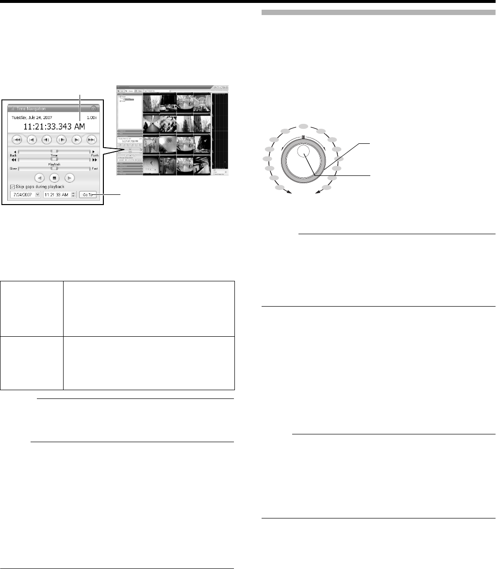
33
䢇Playing Back
1 Press the [PLAY] button
●Playback starts from the date/time indicated in [Master
Time] of [Time Navigation].
●Images are played back according to the angle of the
shuttle dial (x1/20, x1/5, x1, x2, x5, x10, x20).
䢇Skipping
1 Press the [SKIP] button
●The [SKIP] buttons have the following functions.
Memo :
●“Sequence” indicates a certain block of images that are
recorded during motion detection.
●Recorded images are stored in the database.
Note :
●The [SKIP] buttons are only enabled when a camera has
been selected.
●During simultaneous recording and playback, an AAfter
Database EndB message may appear as playback
catches up with recording during playback near the
current time.
●When recording is set to be triggered by motion/event
(A Page 51), VR-N1600U/E will not start recording unless
a motion/event occurs. During playback near the current
time, however, the image that is not recorded will also be
played.
䢇Stopping
1 Press the [STOP(PB)] button
●Playback stops.
䢇Enlarging the Display
●Pressing a number that corresponds to the selected
camera enlarges the display.
●To restore display to the normal size, press the number of
the camera with enlarged display.
Adjusting the Playback Speed (Jog/Shuttle
Playback)
You can adjust the playback speed by turning the jog dial/
shuttle dial on the front panel.
䡵
Shuttle Playback
●Rotate the shuttle dial during playback or when playback
is paused to start fast forward, fast reverse or slow
playback.
Memo :
●The playback speed that is indicated during fast forward or
fast reverse playback by rotating the shuttle dial is an
approximate value. The speed may differ depending on
the conditions, such as the playback mode (multi-view,
single view) and the recording mode (motion detection,
recorded frame rate).
䡵
Jog Playback
●Rotate the jog dial to play back frame by frame.
●Rotate the dial clockwise to play back a single frame in the
forward direction, and rotate the dial counterclockwise to
play back a single frame in the reverse direction.
●Release the dial to pause the playback. However, when
frames are played back successively in the forward or
reverse direction, playback may continue momentarily
after the jog dial is released.
Note :
●The jog dial is only enabled when a camera has been
selected.
●When the playback speed is adjusted or when playing
back at high speed during recording, the frame rate of the
recording may decrease. Check the performance meter
while adjusting the playback speed to ensure that the
display does not turn red.
SMoves to the first image in the previous
sequence.
Moves to the oldest image in the database
of the selected camera when the button is
pressed and held down..
TMoves to the first image in the next
sequence. Moves to the first image in the
next sequence. When pressed and held
down, moves to the latest image in the
database for the selected camera.
NVRViewer
[Master Time] area
[Time Navigation] Section
[Go To] Button
[Browse] Screen
still
x1
x2
x5
x10
x20
x1/20
x1/5
x1
x2
x5
x10
x20
x1/20
x1/5
REV FWD
Jog/Shuttle dial
Shuttle dial (Outside)
Jog dial (Inside)
VR-N1600_J.book Page 33 Wednesday, August 8, 2007 3:32 PM
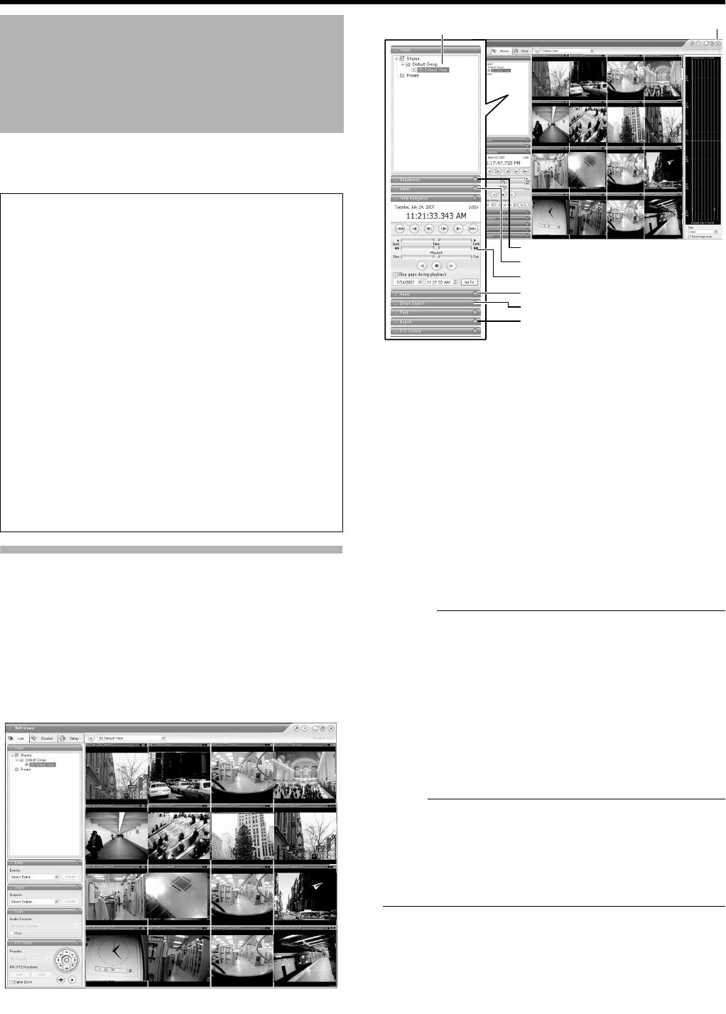
34
Basic Operation
This section describes the procedures for viewing recorded
images by controlling the mouse.
Displaying the [Browse] Screen
1 Select [Live] from the main menu
●The NVR Viewer starts up and the [Live] screen
appears.
2 Double-click the [Browse] tab on the NVR
Viewer.
●Similarly, click the [Browse] tab when the [Screen
Setup] screen of the NVR Viewer is displayed.
●It may take a few minutes before the [Browse] screen is
displayed.
●If you have specified the camera recording settings
without closing the [Browse] screen, the playback
images may not appear immediately after you have
exited the camera settings.
In this case, AUnable to connect to the server!
Reconnecting to the serverB or AUnable to connect to
127.0.0.1:80 on the device name(camera name)!
Reconnecting to the serverB will appear on the
[Browse] screen. (127.0.0.1:80 is the IP address of the
VR-N1600U/E that is currently in operation.)
●If playback is executed when no image is recorded, the
AConnection:[NVR]Camera1 on 127.0.0.1:80B
message will continue to appear on the Playback
screen.
●To exit the NVR Viewer, click the Close button.
Memo :
●Each image bar comes with an online indicator at the top
of the [Browse] screen. The indicator lights up in green
each time a new image is displayed.
●Recorded images are saved in the database. “Database”
refers to data recorded in this unit.
●When ABefore Database StartB appears on the [Browse]
screen, no database (recorded image) is found in the
position prior to the currently viewed image.
●When AAfter Database EndB appears on the [Browse]
screen, no database (recorded image) is found in the
position after the currently viewed image.
Note :
●If several sections are opened on the left side of the
[Browse] screen, it may not be possible to display them all
in the screen. In this case, double-click the section bars to
close the sections.
●Do not switch the view frequently between [Live] and
[Browse] within a short time interval.
Playing Back Recorded
Images via Mouse Control
Notes:
●The recording frame rate may decline when you are
using the [Browse] screen.
●When access to the hard disk occurs frequently, such
as when recording and playback of recorded images are
performed simultaneously, the playback image may
pause and the audio sound may be interrupted. (This
has no impact on recording to the system or additional
hard disk.)
●The audio setting is set to ANo Audio SourcesB when
you return from the setting screen to [Browse]. Select
the audio parameters again.
●Set the time zone of the PC to the same time zone as
VR-N1600U/E. If recorded images are viewed on a PC
with a different time zone, the time displayed on the
recorded images of VR-N1600U/E will be converted to
the time in the PC’s time zone.
●When changes are made to the time zone in [OS
Setting], press and hold the [FUNCTION] button, and
press the [LIVE/BROWSE] button at the same time to
reboot the NVR Viewer.
[Browse] Screen
NVR Viewer
[Views] Section
[Sequence] Section
[Alerts] Section
[Time Navigation] Section
[Audio] Section
[Smart Search] Section
[Export] Section
[Browse] Screen
[⳯] Button
VR-N1600_J.book Page 34 Wednesday, August 8, 2007 3:32 PM
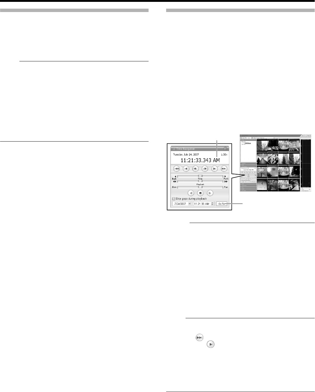
35
Select a view
For details on the view settings, refer to [Screen Setup] (A
Page 54).
1 Select a view from the [Views] section, or from
the view list at the upper end of the window
Note :
●Do not switch the view frequently within a short time
interval.
●When live images do not appear on VN-C625/VN-C655,
set the password on the camera unit as well as VR-
N1600U/E again. For details on the setting procedures,
refer to the [INSTRUCRTIONS] of the camera in use and
procedures for setting the root password on the [Edit
device settings] screen in this manual (A Page 75).
●The audio setting is set to ANo Audio SourcesB when you
return from the setting screen to [Live]. Select the audio
parameters again.
Searching Recorded Image Using [Time
Navigation]
You can search recorded images using [Browse] on the
[Time Navigation] screen as follows.
1 Double-click the [Time Navigation] bar on the
[Browse] screen
2 Select the search date/time from the box
●Specify the date in the left box and the time in the right
box.
3 Click the [Go To] button
●The view in the image display screen jumps to the
specified date and time.
●The specified date and time will appear in the master
time area.
Memo :
●The master time area displays the recording date and
time of the selected playback images. The master time is
the time to which all the cameras are linked, and when
you specify a time, all the recorded images you see in
[Views] will be accurately displayed.
●There are cases when there is no recorded image on
motion detection or on the specified date/time among the
multiple cameras within the view. In this case, the last
image in the camera’s database prior to the specified
point in time is displayed in the view. (Recorded images
are saved to the database.)
●The [Master Time] area also displays the currently
selected playback speed.
Note :
●The master time area may display an exceeded record
date and time of the latest recorded image. In this case,
click the button to move to the latest recorded image,
and click the button.
●When ASkip gaps during playbackB in the [Time
Navigation] section is ticked, playback may stop when it
exceeds the end of the recorded portion during
simultaneous recording and playback. In this case,
deselect the tick in [Skip gaps during playback]. If
playback stops, click the Play button again.
NVRViewer
Master Time area
[Time Navigation] Section
[Go To] Button
[Browse] Screen
VR-N1600_J.book Page 35 Wednesday, August 8, 2007 3:32 PM
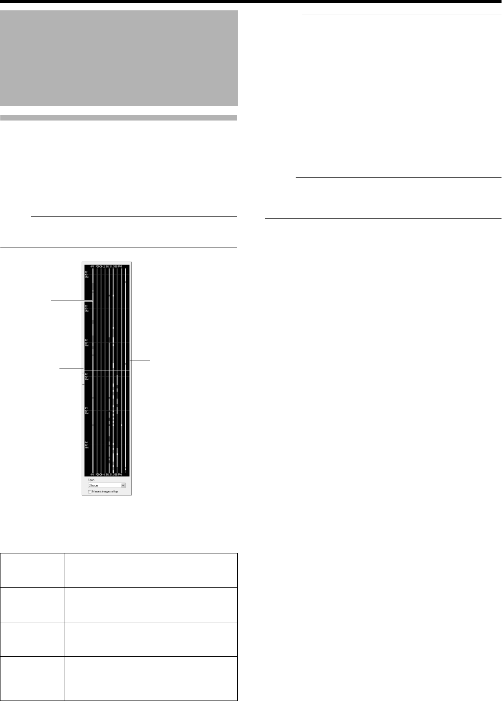
36
Basic Operation
Searching Recorded Image Using the Timeline
Browser
You can search recorded images using the timeline browser
on the right of the [Browse] screen.
The vertically extended timeline shows the recording status
and the number of cameras that can be displayed in the NVR
Viewer. Drag the timeline up or down with the mouse while
checking the time display pointer.
Note :
●The timeline is an approximate value. Therefore, the
display may not coincide with the actual time.
䡵
Timeline Colors and Lines
The timeline of the camera selected in the view is highlighted
in a lighter color.
Memo :
●The items under the timeline browser enable you to
specify the time span to display on the timeline (1 hour, 2
hours, etc. up to 1 day), and whether to set the time flow
from top to bottom or bottom to top by using the [Newest
images at top] check box. These settings will not be
saved. They will be lost each time the NVR Viewer is
rebooted.
●If your mouse has a scroll wheel, you can also use the
scroll wheel for browsing the timelines.
●Double-click on any point within the timeline to display
image at the desired point in time.
●When you do not need the timeline browser, you can hide
it by clicking the [Display ON/OFF] button at the center of
the timeline browser’s left edge.
Note :
●A portion of the timeline may not be refreshed if you drag
the timeline up and down using the mouse. In this case,
reboot the NVR Viewer (A Page 25).
Playing Back Recorded
Images via Mouse Control
(continued)
Red Indicates recordings of motion detection or
events.
(Pink when highlighted.)
Green Shows recordings before and after motion
is detected.
(Light green when highlighted.)
Black Indicates the period during which there is
no recording.
(Gray when highlighted.)
Center White
Line (Time
Display
Pointer)
Shows the time of the displayed image.
[Timeline Browser]
Display ON/
OFF Button
Time Display
Pointer
Timeline
VR-N1600_J.book Page 36 Wednesday, August 8, 2007 3:32 PM
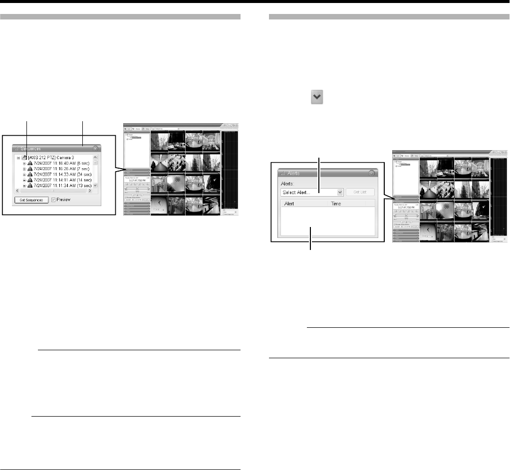
37
Searching Recorded Image Using Sequence
Sequences refers to sequences of images that are recorded
when an event or motion is detected. Each sequence
contains a list of the recorded images.
1 Double-click the [Sequence] bar on the [Browse]
screen
2 Click [Get Sequence]
●A list of 20 images each prior to and following the
display time appears.
●If the [Preview Image] check box is selected, you are
able to preview the images by placing the mouse
pointer over the sequence in the list.
3 Click a sequence in the list
●Display of all the images in the view changes according
to the date/time of the selected sequence.
Memo :
●Clicking the expand icon [+] next to a sequence in the list
will show you the exact date and time of the first and last
image in the sequence as well as the exact date and time
of the motion detection or event that triggered the
recording.
Note :
●Depending on [( )seconds pre/post recordings on
motion/event:] (A Page 51), a consecutive number of
sequences may sometimes be integrated into one
sequence.
Searching Recorded Image from the Alert List
A list of recorded images is displayed for each [Alart], such
as when motion is detected (A Page 92).
1 Double-click the [Alerts] bar on the [Browse]
screen
2 Click [ ] on the [Alerts] list and select an event
from the list
●You can select a specific event, camera or [Server].
3 Click the [Get List] button
●A list of detected events appears.
●You can click on the event list to view recorded images
of the selected event.
Memo :
●The Alerts list displays events occurring around the time
(approx. 1 day before and after) set in [Time Navigation].
NVRViewer
[Browse] Screen
[Sequence] Sequence Bar
NVRViewer
[Alerts] List
Event List [Browse] Screen
VR-N1600_J.book Page 37 Wednesday, August 8, 2007 3:32 PM
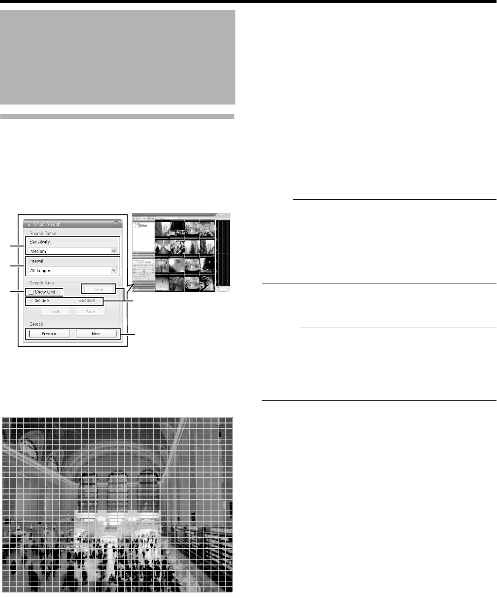
38
Basic Operation
Smart Search
Smart Search enables you to search the parts with motion by
specifying the search area within the recorded images of the
selected camera.
1 Double-click the [Smart Search] bar on the
[Browse] screen
2 Tick [Show Grid] in [Search Area] setting
3 Select the camera to display
●A blue grid overlay appears.
4 Click and drag within the screen to specify the
search area.
●The areas that you have selected become transparent.
●Select the [Include] check box to add the area selected
by dragging to the search area. Select the [Exclude]
check box to remove the area selected by dragging
from the search area.
●Click the [Invert] button to reverse the area selection.
5 Select the sensitivity level from the [Sensitivity]
list in [Search Setup]
●The setting values are as follows.
●[Very High]
●[High]
●[Medium]
●[Low]
●[Very Low]
6 Set the time interval in the [Interval] list
7 Press the [Previous] or [Next] button to search
through data for which motion has been
detected within the area
●Smart Search begins. When motion is detected inside
the selected area, it will be highlighted in the view.
Note :
●Smart Search is carried out in the [forward] and
[backward] directions from the time of the image you are
viewing.
●Smart Search that is performed during recording may
lower the recording frame rate. Check the performance
meter while adjusting the playback speed to ensure that
the display does not turn red.
8 To continue searching, click the [Previous] and
[Next] buttons
Memo :
●You can use the [Save] button to temporarily save the area
that you have selected in Step 4.
To return to the saved area settings, click the [Load]
button after selecting another area.
●To cancel the area selection, tick [Exclude] and drag all
the areas.
Playing Back Recorded
Images via Mouse Control
(continued)
NVRViewer
24
5
6
7,8
[Browse] Screen
VR-N1600_J.book Page 38 Wednesday, August 8, 2007 3:32 PM
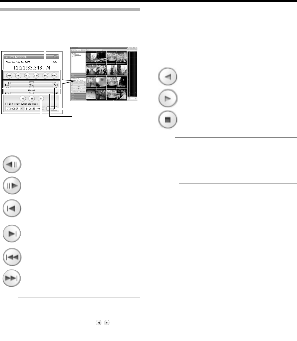
39
Playing, Skipping and Stopping Recorded Images
Use the [Time Navigation] of the NVR Viewer to perform
playback, stop, and skip operations.
The buttons and sliders have the following functions.
䢇Browse Button
Note :
●The browse buttons are only enabled when a camera has
been selected.
●It may take several minutes for moving to complete after
you have pressed the browse buttons . Note that if
the buttons are clicked continuously before the images are
moved, the selected sequences will be moved collectively.
䢇[Time] Slider
Dragging the slider to the left changes the recording date to
an older date, and dragging the slider to the right changes it
to a more recent date. Use the top slider bar for fine browsing
(x0.4 to x240) within a limited period of time, and use the
bottom bar for easy browsing (x20 to x36,000) for longer
time spans.
䢇[Playback] Slider
The center position is for playback at normal speed (x1).
Drag the slider to the left and right to reduce and increase
the playback speed respectively. Dragging the slider to the
leftmost position pauses playback.
The playback speed is displayed at the top right of the
master time area.
●Play Button
Note :
●The Playback buttons do not work when the [Playback]
Slider is placed at its leftmost position (paused). Select
the desired speed by moving the [Playback] Slider.
●The angle of the shuttle dial does not affect playback,
which is operated in the [Time Navigation] section using a
mouse.
Memo :
●When ASkip gaps during playbackB of [Time Navigation] is
checked, playback is performed by skipping portions for
which no recorded image is found in the selected camera.
●When the recorded images are played back with some
images skipped, the [SKIP] display will appear in red in
the [Master Time] area for some time.
●During playback, skip playback operations may differ
between a single screen and multiple screens. Even if the
selected camera does not contain any recording, skipping
will not take place as long as recording is found in another
camera. If recorded images are not found, the previously
displayed image appears.
:
Moves to the previous image of the selected
camera (frame-by-frame reverse playback).
:
Moves to the next image of the selected camera
(frame-by-frame forward playback).
:
Moves to the first image in the previous
sequence of the selected camera. (This function
may not work properly if there is no sequences
or for some sequence lengths.)
:
Moves to the first image in the next sequence of
the selected camera. (This function may not
work properly if there is no sequence or for
some sequence lengths.)
:
Moves to the oldest recorded image of the
selected camera. (This function may not work
properly at a playback speed of 10x or higher.)
:
Moves to the latest recorded image of the
selected camera. (This function may not work
properly at a playback speed of 10x or higher.)
NVRViewer
Browse Button
[Time] Slider
[Playback] Slider
Play Button
[Browse] Screen
: Plays back images in the reverse direction.
: Plays back images.
: Stops playback.
VR-N1600_J.book Page 39 Wednesday, August 8, 2007 3:32 PM
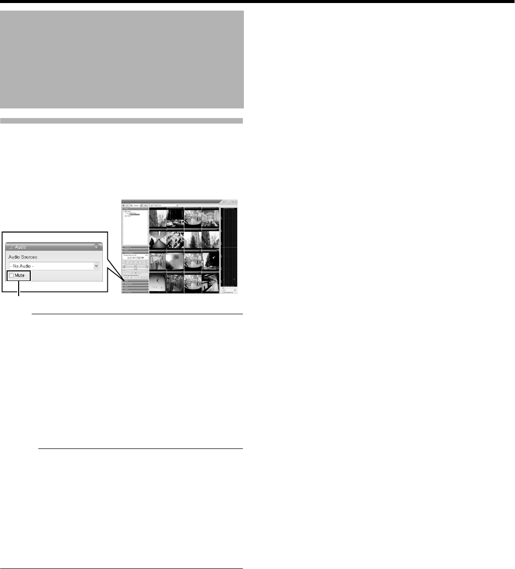
40
Basic Operation
Listening to Audio Sound
To listen to recorded audio sound, select the required audio
source from the [Audio Source] list of the [Audio] section.
To temporarily mute the live audio sound, select the [Mute]
check box.
Note :
●The sound may become distorted when audio is played
back with multiple surveillance computers.
●The audio setting is restored to [No Audio Sources] when
you return from screen display setting to the [Live] or
[Browse] screen. To listen to an audio sound, reselect an
audio source from the [Audio Source] list.
●There will be no audio output during still image playback
or search/frame advance playback except at the speed of
⳯1.
●When a recorded image is played back during recording,
the played back audio sound may be interrupted.
Memo :
●If you have selected an camera that has been set to
record an audio sound, the specified audio sound will be
output.
●If you have selected a camera that is not set to record an
audio sound, the most recently played back audio sound
will be output continuously.
●During simultaneous recording and playback of recorded
images, the playback image may pause and the sound
may be interrupted. (This has no impact on recording to
the system or additional hard disk.)
Playing Back Recorded
Images via Mouse Control
(continued)
NVRViewer
[Browse] Screen
Select
VR-N1600_J.book Page 40 Wednesday, August 8, 2007 3:32 PM
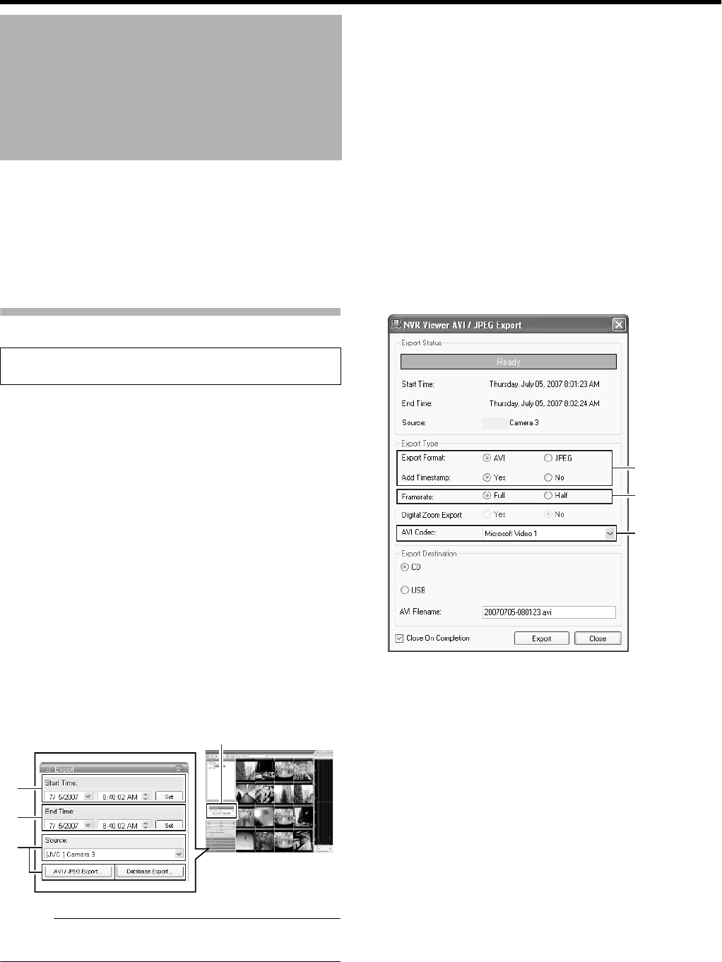
41
You can write (export) recorded images or audio sound to
other media.
●The VR-N1600U/E unit enables you to write images and
audio sound to a CD-R, CD-RW, or USB memory device.
●On a surveillance computer, you can write recorded
images and audio to the desktop or to any folder you
select.
Burning a CD(Operate from the VR-N1600U/E unit)
1 Double-click the [Export] bar on the [Browse]
screen
2 Enter the start date and time
●Click the [Set] button to automatically input the date/
time on the master time area.
3 Enter the end date and time
●Click the [Set] button to automatically input the date/
time on the master time area.
4 Select a camera from the [Source:] list, and click
the [AVI/JPEG Export...] or [Database Export...]
button
●You can also select [-Current View Source-] when
selecting the source. When [-Current View Source-] is
selected, images from all cameras within the view are
exported.
●This export dialog appears. The specified start time,
end time, and camera are shown in the dialog.
Memo :
●Export preparation may take some time depending on
how the external hard disk drive is connected.
5 Select the export format if you have selected
[AVI/JPEG Export...]
●Select either [AVI] (movie clip) or [JPEG] (still image).
●Select whether to add time stamps to the exported
images.
6 Select the required frame rate if you have
selected the [AVI] format
●Select either the [Full] option, which sends all images
to the AVI file, or the [Half] option, which reduces the
size of the AVI file by sending images on a per second
basis (though images will still be played back in real-
time).
7 If you have selected the [AVI] format, select [AVI
Codec] from the [AVI Codec] list and enter the
file name
●
The default file name is
A
yyyymmdd-hhmmss.avi
B
.
Writing Images/Audio
Sound to CDs and Other
Media (Export)
●Steps 1 to 9 are common procedures for writing to CDs
and USB memory devices.
NVRViewer
2
3
4
[Browse] Screen
Master Time area
5
[NVR]
6
7
VR-N1600_J.book Page 41 Wednesday, August 8, 2007 3:32 PM
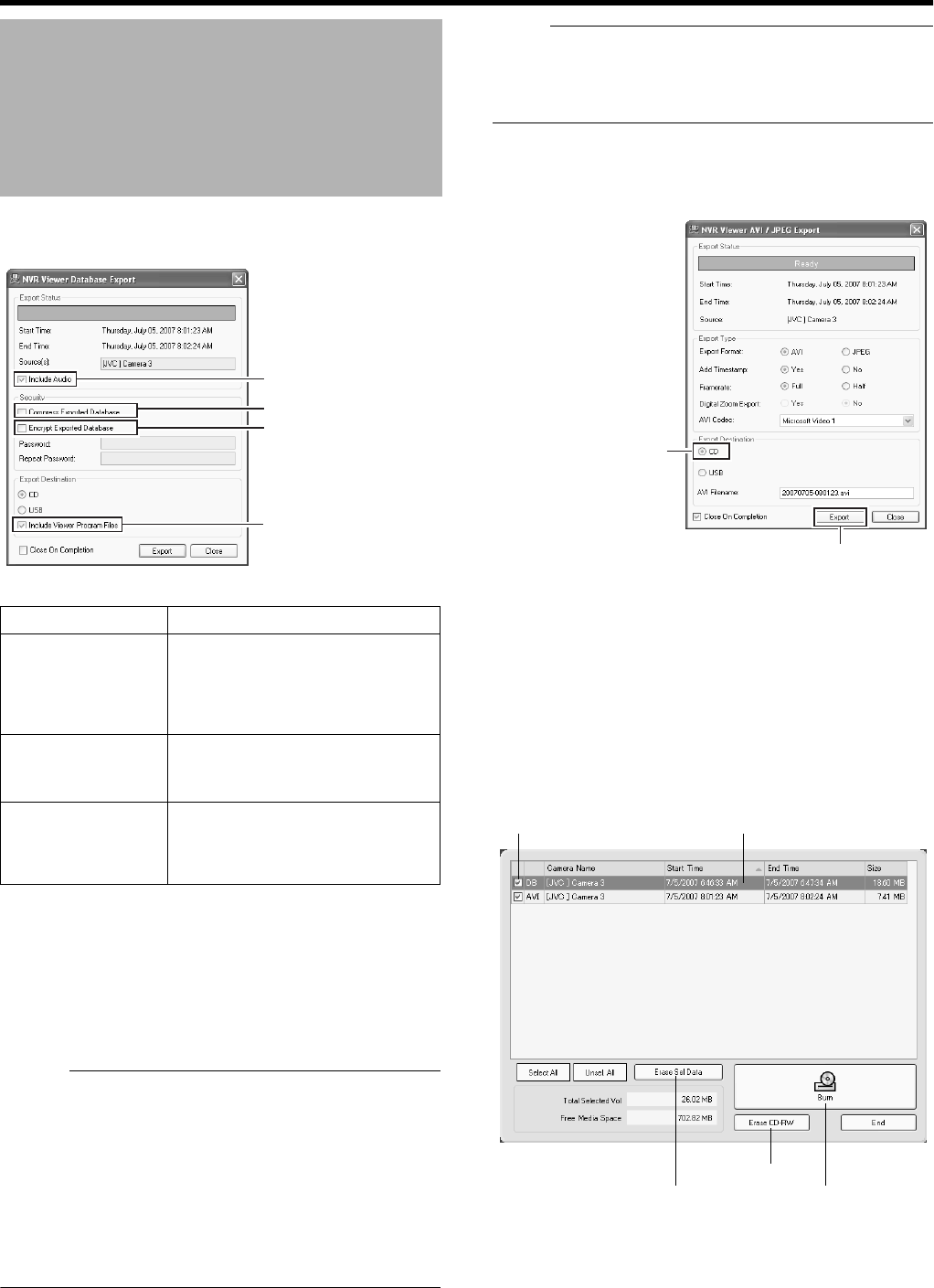
42
Basic Operation
8 If you have selected [Database Export...], setting
of the following items will be enabled.
9 Assign a stand-alone Viewer (application for
playing recorded images) to the data to be
exported
●If you selected [Database Export...], you are able to
include a stand-alone version of the viewer (application
for playing recorded images) to the data to be exported
by selecting the [Include Viewer Program Files] check
box.
Memo :
●To view the exported data on a PC, double-click the
[Browser.exe] file in the [Exported Images] folder of the
USB memory or CD-R/RW used for the export. It will open
the Viewer and you can view the exported data.
●For details on the Viewer, refer to [Export Viewer] (A
Page 117).
●DB To include audio sound by exporting in the AVI format,
open the recorded image that has been exported in the
DB format on the Viewer, and export it again in the AVI
format on the Viewer.
Note :
●The [Database Export...] format enables you to export
audio sound together, which is not possible when you
export in the [AVI] or [JPEG] format.
●The recording frame rate may decline during export.
10 Specify the export destination
To write data to a CD, select [CD].
11 Click [Export]
●Export begins to prepare for writing data to the CD.
12 When export is complete, connect the CD
drive to VR-N1600U/E
13 Press and hold the [FUNCTION] key in front,
and press [4] on the keypad
●The Burn CD screen appears.
Writing Images/Audio Sound
to CDs and Other Media
(Export) (continued)
Item Description
AInclude Audio Tick this box if you wish to include
audio sound in the image to export.
(You cannot select this check box if
the audio source does not contain
any data.)
BCompress
Exported
Database
Select this check box to compress
the exported database.
CEncrypt
Exported
Database
Select this check box to encrypt the
exported database. Specify a
password for subsequent
decryption.
A
B
C
9
11
[CD] Check Button
Check Box Data List
Burn CD Screen
[Erase Sel Data]
Button
[Erase CD-RW]
Button [Burn] Button
VR-N1600_J.book Page 42 Wednesday, August 8, 2007 3:32 PM
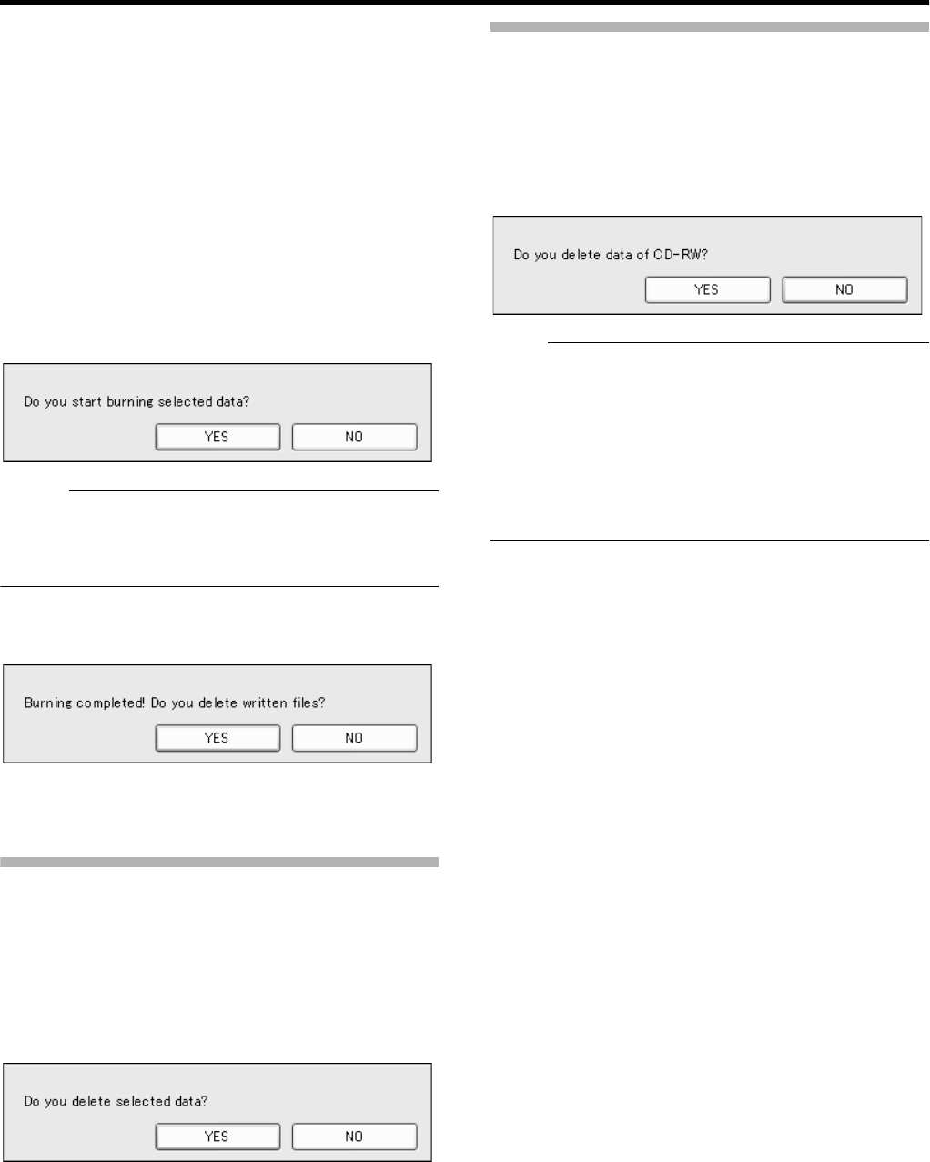
43
14 Insert the media (CD-R or CD-RW) that you
want to write data to into the CD drive.
●The space available in the media is shown in [Free
Media Space].
●The [Burn] button is enabled (operable).
15 Select the check boxes for the AVI/JPG/DB
files that you want to write to the CD from the
data list.
●The total volume of the selected data will appear in
[Total Selected Vol].
●To select all the files, click the [Select All] button.
●To deselect all the files, click the [Unsel.All] button.
16 Press the [Burn] button
●A [YES] or [NO] message asking you whether to start
writing appears. Select AYESB.
Memo :
●If no file has been selected from the data list, an error will
occur.
●If the total volume of the selected data exceeds the
available memory space in the media, an error will occur.
17 When writing is complete, the following
message appears.
●To delete the temporary files, select AYESB.
●To write the same data to another CD, select ANOB.
Deleting Temporary Files (Operation on the VR-
N1600U/E Unit)
1 Select the temporary files you want to delete
from the data list.
2 Click the [Erase Sel Data] button
A [YES] or [NO] message asking you whether to delete the
selected data appears. Select AYESB.
Deleting Data from a CD-RW (Operation on the VR-
N1600U/E Unit)
1 Insert the CD-RW
●The [Erase CD-RW] button is AenabledB.
2 Click the [Erase CD-RW] button
●A [YES] or [NO] message asking you whether to delete
data in the CD-RW appears. Select AYESB.
Note :
●You cannot perform other operations while data is being
written to the CD.
●Recorded images may be omitted during writing to the CD
(temporary recording error).
●Do not display the Burn CD screen during export.
●Do not connect the CD drive while the media is inserted.
●Do not disconnect the CD drive while the Burn CD screen
is displayed.
●If the media is not detected, restart the Burn CD screen.
VR-N1600_J.book Page 43 Wednesday, August 8, 2007 3:32 PM
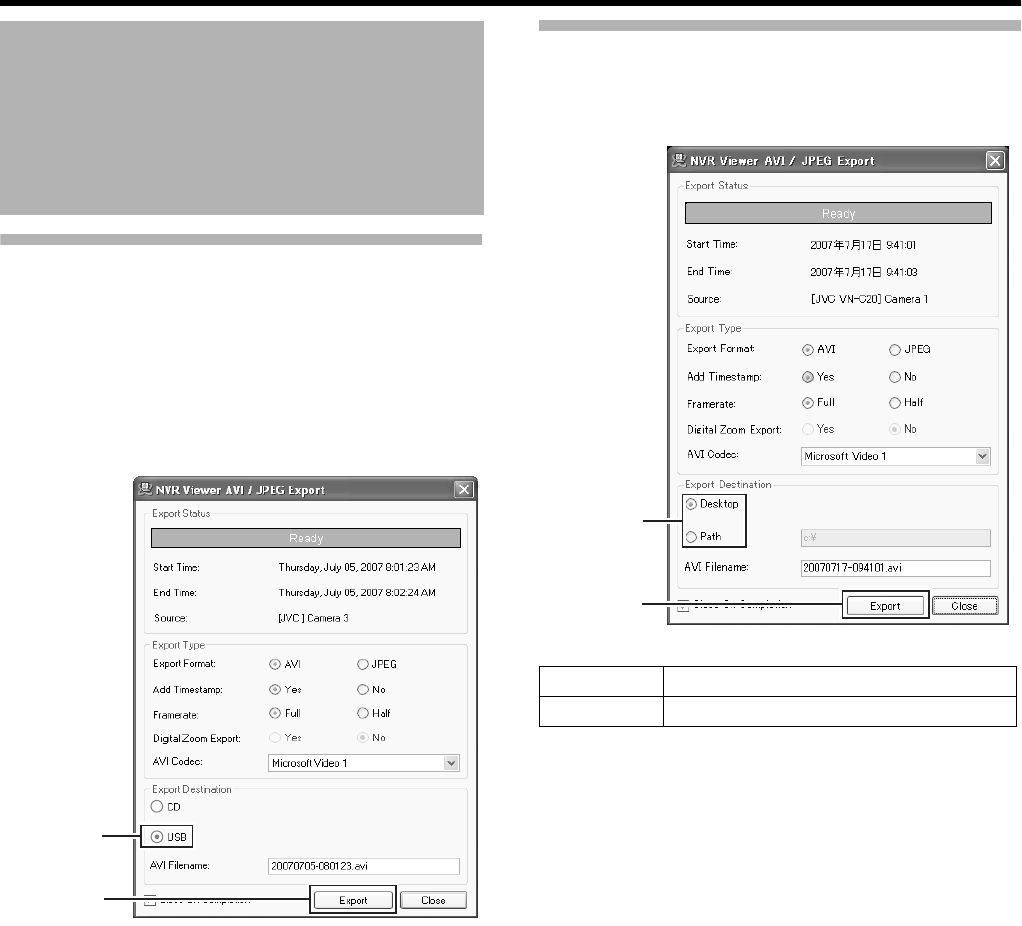
44
Basic Operation
Writing Data to a USB Memory Device (Operation
on the VR-N1600U/E Unit)
Insert the USB memory device that you wish to export data
to, and perform the same procedures in [Burning a
CD(Operate from the VR-N1600U/E unit)] from Steps 1 to 9
(A Page 41).
1 Specify the export destination
●To export to a USB memory device, select [USB].
2 Click [Export]
●Export begins.
Operation from a Surveillance Computer
Use Steps 1 to 9 in “Writing Data to a CD” (A Page 41).
1 Specify the export destination
2 Click [Export]
●Export begins.
Writing Images/Audio Sound
to CDs and Other Media
(Export) (continued)
2
[USB] Check
Button
Desktop Use this to export to the desktop.
Path Use this to export to a selected folder.
1
2
VR-N1600_J.book Page 44 Wednesday, August 8, 2007 3:32 PM
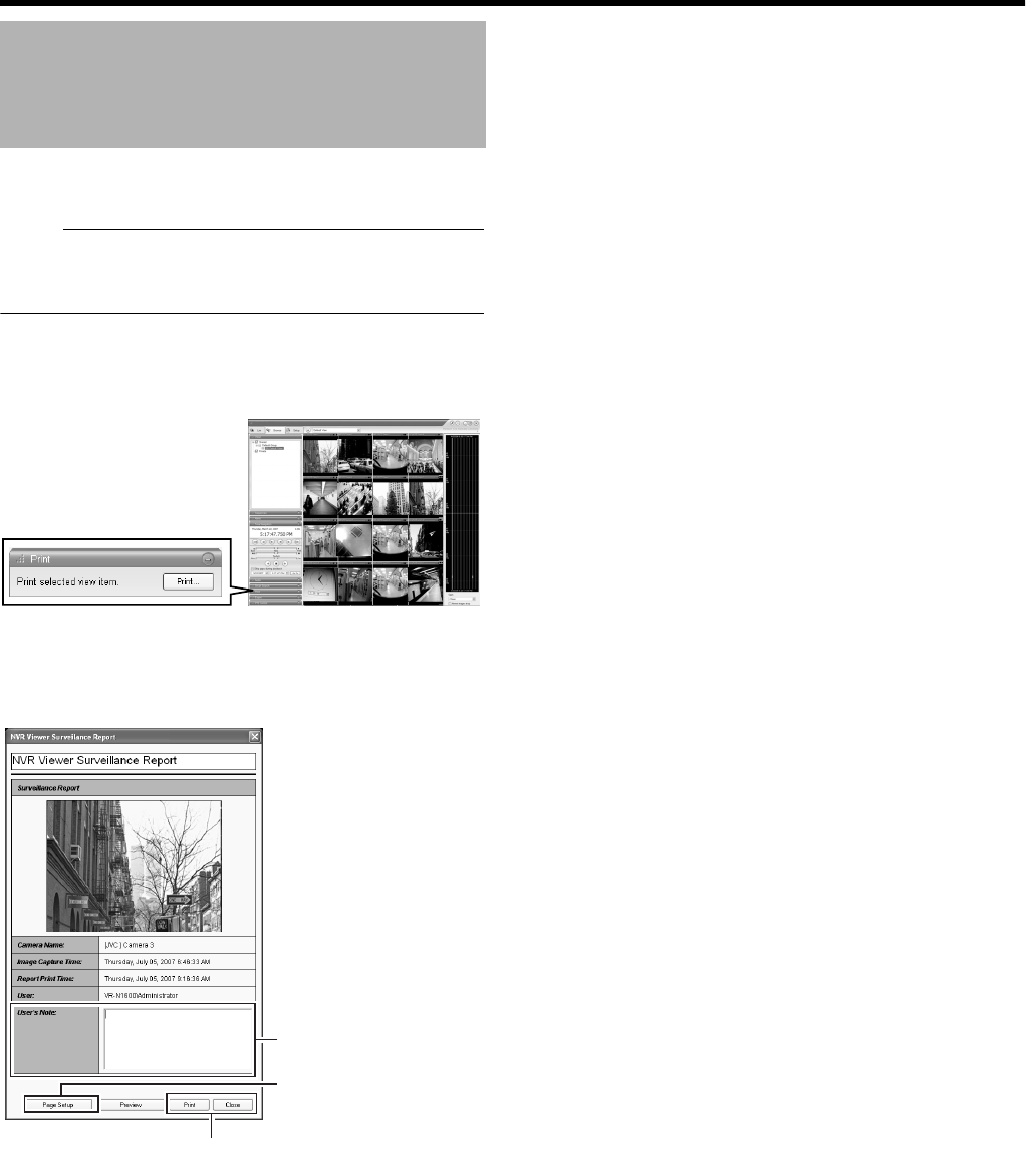
45
You can print out playback images that are displayed on the
screen.
Note :
●Printing directly from the VR-N1600U/E unit is not
possible. This function is for use by the [NVR Viewer],
which is downloaded onto the surveillance computer.
1 Double-click the [Print] bar on the [Browse]
screen.
2 Click the [Print...] button in the [Print] section.
●The [NVR Viewer Survellance Report] screen appears.
3 Click the [NVR Viewer Survellance Report]
button on the [Page Setup] screen to specify the
printer settings
4 Click the [Print] button to start printing
●After printing ends, click the [Close] button to close the
print window.
●Comments entered in [User's Note] are also printed.
Printing Recorded Images
NVRViewer
[Browse] Screen
4
3
[User's Note]
VR-N1600_J.book Page 45 Wednesday, August 8, 2007 3:32 PM

46
Basic Operation
Recording Modes
䡵
Recording Control Mode (
A
Page 47)
This mode performs recording according to the [Camera Record
Setting].
The [REC CONTROL] indicator lights up.
You can switch the recording control mode on or off by pressing and
holding the [REC CONTROL] button.
●
Set each camera to on/off using the [Scheduler...] settings
(
A
Page 47).
●
Specify the frame rate and conditions for starting recording in
[Camera Settings] (
A
Page 49).
Note :
●
During the interval that is set as offline in [Scheduler...],
recording will not be performed regardless of the [Camera
Settings].
●
The [REC CONTROL] button is
A
disabled
B
when the main menu
is displayed, when settings are being specified, and during
recording.
●
When there is an unconnected camera, it may take a while
before the [REC CONTROL] indicator lights up.
Memo :
●
Press the [REC/STOP] button to cancel the
A
recording control
mode
B
and enable manual recording mode.
●
Press and hold down the [REC/STOP] button to cancel all
A
recording modes
B
and stop recording.
●
Setting [Operate] to ON switches the mode automatically to the
A
recording control mode
B
. (When [Record Control] under [Unit
Setting] of the main menu is set to
A
ON at startup
B
.) )
䡵
Manual Recording Mode
The manual recording mode executes recording from all cameras
regardless of the [Camera Record Setting]. Recording is executed
in the frame rate specified in [Recording Settings]
-
[Desired
framerate] of the [Camera Settings] screen.
Manual recording lets you start and stop recording on all cameras
by using the [REC/STOP] button. Press the [REC/STOP] button to
start recording. Press and hold down the [REC/STOP] button to
stop recording.
The [REC CONTROL] indicator lights up.
䡵
[EXT REC IN] Signal Recording Mode
Recording starts on all cameras when the [EXT REC IN] terminal of
the rear input/output terminal is set to MAKE. Recording is executed
in the frame rate specified in [Recording Settings]
-
[Desired
framerate] of the [Camera Settings] screen.
Recording by [EXT REC IN] signal has priority over recording
control mode or manual recording.
When recording by the [EXT REC IN] signals is complete, the
cameras return to the original recording mode.
Memo :
●
When recording using signals from the [EXT REC IN] terminal,
the light of the [REC CONTROL] indicator goes off, and the
[REC] indicator appears blinking.
●
Emergency recording lets you start and stop recording on all
cameras regardless of the [Scheduler...] settings or [Camera
Settings].
●
Pressing the [REC/STOP] button cancels recording by signals
from the [EXT REC IN] terminal and switches automatically to
the
A
manual recording mode
B
. The [REC] indicator also
changes from
A
blinking
B
to the
A
lit
B
mode.
●
Pressing and holding down the [REC/STOP] button cancels
recording by signals from the [EXT REC IN] terminal and stops
recording.
䡵
Emergency Recording Mode
Recording starts on all cameras when a MAKE signal is detected by
the [EMERGENCY] terminal of the rear input/output terminal.
Recording is executed in the frame rate specified in [Recording
Settings]
-
[Desired framerate] of the [Camera Settings] screen.
Recording is only executed during the time specified in [Emergency
Record] of [Unit Setting](
A
Page 63).
Emergency recording has priority over recording control mode or
manual recording mode.
When emergency recording is complete, the cameras return to the
original recording mode.
Memo :
●
The [REC CONTROL] indicator goes off and the [REC] indicator
appears blinking during emergency recording.
●
Emergency recording lets you start and stop recording on all
cameras regardless of the [Scheduler...] settings or [Camera
Settings].
●
Pressing the [REC/STOP] button cancels emergency recording
and switches automatically to the
A
manual recording mode
B
.
The [REC] indicator also changes from
A
blinking
B
to the
A
lit
B
mode.
●
Press and hold down the [REC/STOP] button to cancel all
recording modes and stop recording.
Note :
●
When in the manual recording, [EXT REC IN] signal recording or
emergency recording mode, motion detection and event
recording settings are ignored.
Recording Operation During Power Failure
If a power failure occurs during recording, the system
resumes recording in the mode selected before the power
failure after recovery.
●In the recording control mode, recording by a motion or
event does not resume unless another motion or event
occurs after recovery from the power failure.
●The recording control mode returns to the status before
the power failure.
Note :
●The recorded images may not be played back properly if
they are not archived (A Page 95) before the power
failure.
●It is recommended that an uninterruptible power supply
(UPS) be used to protect the hard disk from damage in
the event of a power failure. (A Page 112)
●When a power failure occurs while formatting a hard disk
or archiving, subsequent operation may be affected even
when an UPS is connected.
Recording Camera Images
There are four different recording modes.
●Recording Control Mode
●Manual Recording Mode
●EXT REC IN Signal Recording Mode
●Emergency Recording Mode
VR-N1600_J.book Page 46 Wednesday, August 8, 2007 3:32 PM
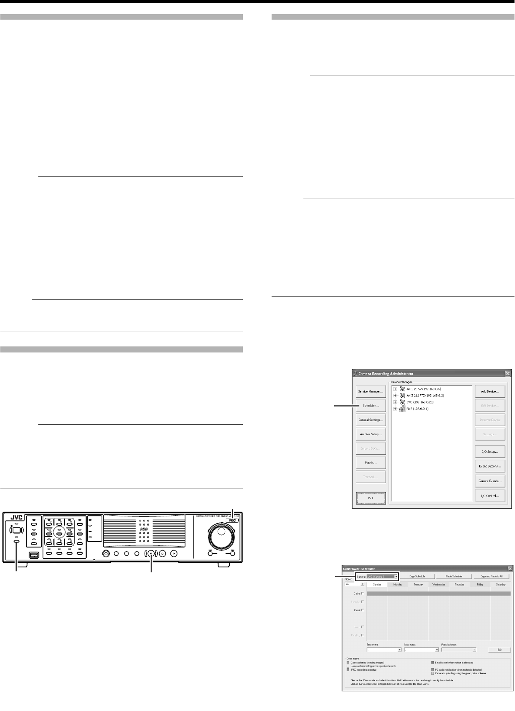
47
Selecting the Recording Control Mode
In order to record in the recording control mode, you need to
specify the scheduler settings (A Page 47), image recording
settings (A Page 49), and picture quality settings (A Page
52) in the main menu [Camera Record Setting].
1 Press and hold down the [REC CONTROL]
button while recording is stopped ([REC]
indicator is off).
●The [REC CONTROL] indicator lights up and the unit
switches to the recording control mode.
●Recording will be executed according to the camera
record settings.
Memo :
●To stop recording, press and hold down the [REC/STOP]
button during recording in a mode other than recording
control (the [REC] indicator lights up or appears blinking).
After the light of the [REC] indicator goes off, press and
hold the [REC CONTROL] button.
●To exit the recording control mode, press and hold down
the [REC CONTROL] or [REC/STOP] button.
●Depending on camera status or other circumstances, it
may take a while before recording starts after switching to
the recording control mode.
Note :
●Do not turn off the power while you are configuring the
camera recording settings.
Selecting the Manual Recording Mode
1 Press the [REC/STOP] button
●The unit switches to the manual recording mode and
starts recording from all cameras.
●The [REC] indicator lights up.
Memo :
●To exit the manual recording mode, press and hold down
the [REC/STOP] button. Upon doing so, the light of the
[REC] indicator goes off.
●To clear all recording modes, press and hold down the
[REC/STOP] button.
Scheduler Setting
This feature lets you specify when to switch each camera to
the online mode, as well as the online/offline mode of
cameras when an event occurs.
Memo :
●When in the online mode, the camera executes recording
according to the camera record settings.
●When in the offline mode, recording is not executed
regardless of the camera record settings.
●You can specify the time zone during which e-mail alerts
are triggered when motion is detected. You can also
specify the time zone to activate automatic patrolling
(A Page 81) when using PTZ cameras.
●The minimum unit of time that you can specify is 5
minutes.
Note :
●The online/offline mode has no impact on the manual
recording, [EXT REC IN] signal recording, and emergency
recording modes.
●Even when AOfflineB or AEventB is specified in the
scheduler, the camera switches to the AOnlineB mode if
[Start cameras on remote live requests](A Page 93)
under [General Settings] is enabled and live images are
displayed on the [NVR Viewer].
1 Select [Camera Record Setting] from the main
menu
2 Click the [Scheduler...] button
●The [Scheduler...] screen appears.
3 Select the camera for which you want to set a
schedule from [Camera].
OPERATE
REC CONTROL
LIVE/BROWSE
SELECT
PTZ/PRESET
SERIAL
㧝 㧞 㧟 㧠
㧡 㧢*1/' 㧣
㧥
㧤
CANCEL ZOOM OUT ZOOM IN ENTER
WARN ING
ALARM
HDD
LOCK
SEARCHFUNCTION ALARM CLEARKEY REC/STOP STOP(PB) PLAY
SKIP
REV FWD
[REC] Indicator
[REC CONTROL] Button/Indicator [REC/STOP] Button
[Camera Recording Administator] Screen
[Scheduler...]
Button
[Scheduler] Screen
Select a Camera
VR-N1600_J.book Page 47 Wednesday, August 8, 2007 3:32 PM
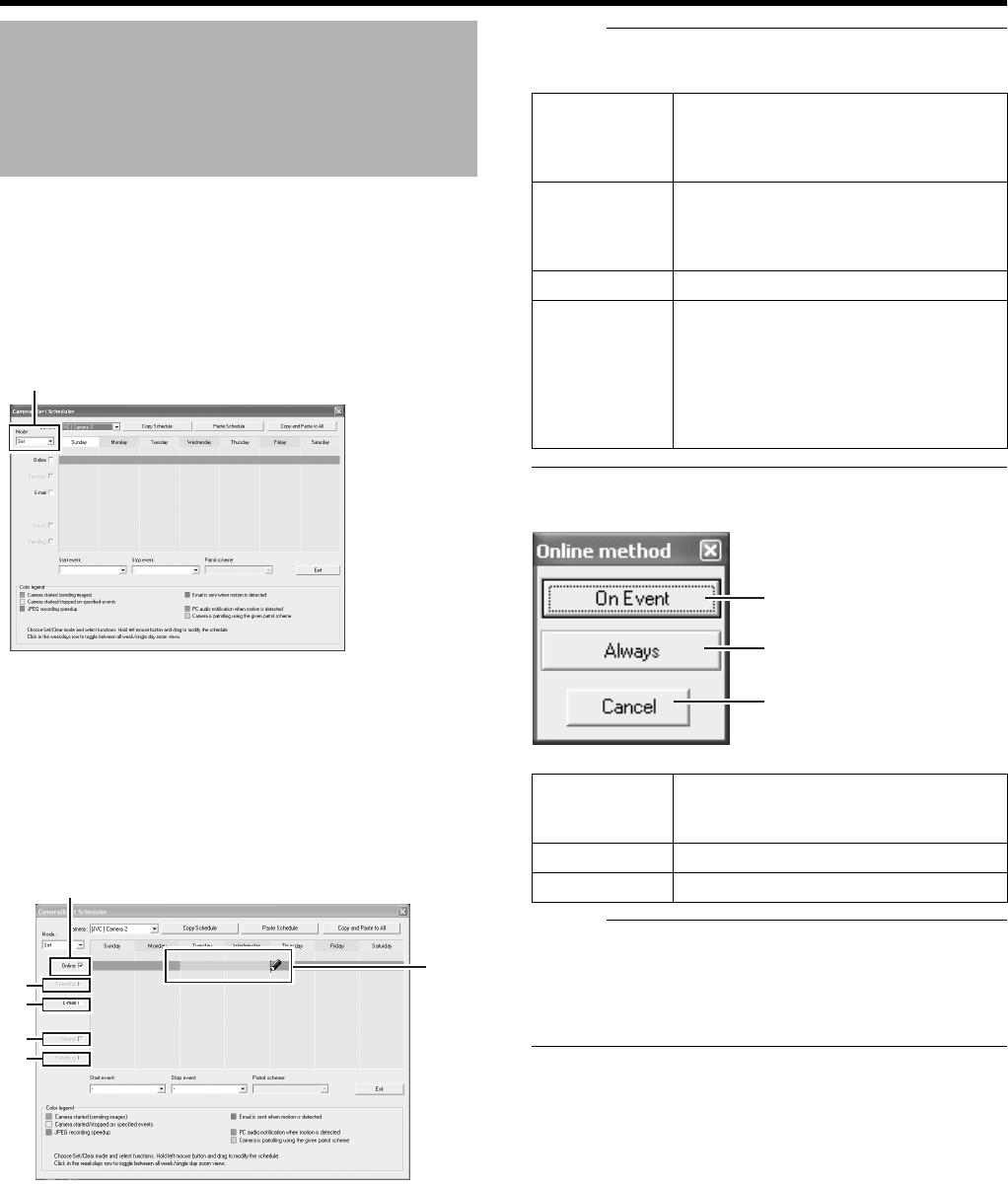
48
Basic Operation
4 Select [Set] from [Mode]
●The mouse pointer turns into a ApencilB.
●Moving the mouse pointer to the day-of-week band in
the calendar section enables you to zoom in/zoom out
on the calendar. Enlarge the calendar to check detailed
schedule.
5 Select the [Online] check box
6 Specify the date to switch online in the calendar
section
●Hold down the mouse in the calendar section, and
move the mouse pointer to specify the date.
●The selected period is indicated in light blue color.
Memo :
●Selecting the [E-mail], [Patrolling], and [Enable speedup]
check boxes enables you to specify the following settings.
7 The Schedule Settings window appears
Memo :
●To clear the period, select [Cancel] from [Mode] at the top
left, select the check box of the item you want to delete
([Online], [E-mail] or [Patrolling]), and move the mouse
pointer while left-clicking the mouse on the period in the
calendar section.
Recording Camera Images
(continued)
[JVC VN-E4]Camela1
Mode
5
6
A
B
C
D
AEnable
speedup
Enables you to specify the period to
enable the speedup function when
speedup in [Settings...] is set to
AEnableB (A Page 50).
BE-mail Enables you to specify the period to
send out the e-mail alert when e-mail
alert notification during an event or
motion is selected (A Page 84).
CAudio You cannot select this check box.
DPatrolling Enables you to specify the patrol
scheme and patrolling period. Select a
patrol scheme from the [Patrol scheme]
list, and specify the corresponding
period in the calendar section. [Patrol
scheme] must be defined in advance.
(A Page 82)
AOn Event Switches to the online mode only when
an event occurs. Specify the event in the
event start/stop item.
BAlways Online mode at all time.
CCancel Cancels the settings.
A
B
C
VR-N1600_J.book Page 48 Wednesday, August 8, 2007 3:32 PM
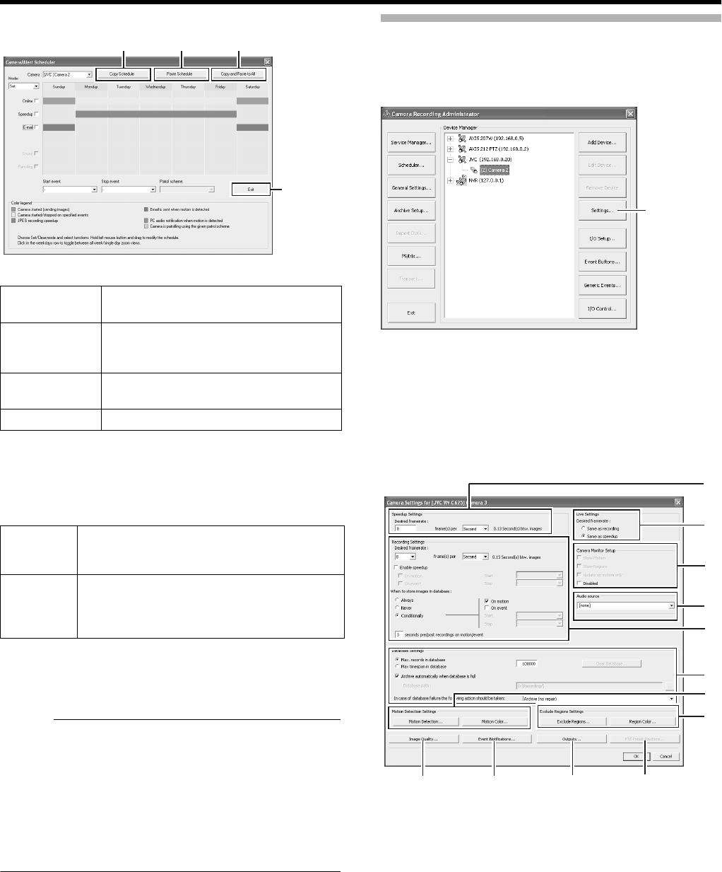
49
䡵
Camera/Alert Scheduler Screen
䢇
Display Bar
The display bar indicates the active period for each option
([Online], [E-mail] and [Patrolling]) in different colors.
䢇Online Bar
䢇E-mail Bar
Active periods are indicated in blue.
䢇Patrolling Bar
Active periods are indicated in gray.
Memo :
●The Patrolling Bar is only available when at least one
[Patrol scheme] has been registered in advance. When
several patrol schemes have been registered and are
used successively, changes between the schemes are
indicated by a thin vertical line. (A Page 82)
●To check the [Patrol scheme], click the bar of the period to
check in the calendar section. The [Patrol scheme]
specified for that period will appear in the [Patrol scheme]
list.
Specifying Image Recording Settings
1 Select [Camera Record Setting] from the main
menu
2 Select a camera from [Device Manager] and click
[Settings...]
●The [Camera Settings] screen appears.
●Specify the setting for each item. (A Page 50)
ACopy
Schedule
Enables you to copy the schedule
displayed in the calendar section.
BPaste
Schedule
Pastes the schedule copied using [Copy
Schedule]A to the schedule of the
selected camera.
CCopy and
Paste to All
Pastes the schedule indicated on the
calendar to all cameras.
DClose Exits the [Scheduler...] screen.
Pink Indicates the period during which VR-
N1600U/E always displays images from the
selected camera.
Yellow Indicates the period during which images
from the selected camera are displayed when
there is input of an event specified in VR-
N1600U/E.
A B C
D
[Camera Recording Administator] Screen
[Settings...]
A
B
E
D
C
G
F
L
H
KJ
I
[Camera Settings] Screen
VR-N1600_J.book Page 49 Wednesday, August 8, 2007 3:32 PM
50
Basic Operation
Settings
(œ: Factory default)
Recording Camera Images
(continued)
Item Preset Values Description
ASpeedup Settings
Frame Rate ^
Enables you to specify the frame rate to acquire from the camera. This is the frame rate during
speedup recording. Make sure that the total frame rate for all cameras within the view on the
[Live] screen is set to 80 ips (image/second) or less for each view.
Note :
●
Do not set a value that exceeds the camera’s capacity.
●
If the frame rate is not specified for the camera, a frame rate that is supported by the
camera is automatically set.
BLive Settings
Frame Rate Same as
recording
䢇Same sa
speedup
Displays the viewing frame rate of the [Live Viewing] screen.
Same sa speedup:
Displays live images using the frame rate specified in the [Speedup Settings] item
A
.
Same as recording:
Displays live images using the frame rate specified in the [Recording Settings] item
E
.
When speedup is set to
A
ON
B
and the recording frame rate increases such as due to detection
of motion, the live viewing rate also increases.
CCamera
Monitor
Setup
Show Motion
Show Regions
Update on motion
only
䢇Disabled
Select
A
Disabled
B
to disable the camera.
DAudio
Source
Audio1
You can select the audio source to play back when a camera is selected in the NVR Viewer.
You can also specify the audio source in the NVR Viewer if the audio source is included in the
source to be exported in the [Database Export...] format. (
A
Page 41 [Writing Images/Audio
Sound to CDs and Other Media (Export)])
This has no impact on audio recording.
ERecording Settings
Desired
framerate
Enables you to specify the recording frame rate. You need to specify a value that is larger than
the [Frame Rate] of the [Speedup Settings] item
A
. Make sure that the total frame rate for all
cameras within the view on the [Live] screen is set to 80 ips (image/second) or less for each
view.
Note :
●
The maximum recording frame rate for this unit is not more than 160 ips. Set the total frame
rate of all cameras to 160 ips or below. When speedup settings are used, restore the frame
rate of the speedup settings to the original value.
●
Recording frame rate may fall below the preset frame rate depending on the signal
processing condition of VR-N1600U/E.
●
Recording frame rate may deteriorate under the following conditions:
●
During export
●
When changing the picture quality of the displayed image
●
When the total frame rate of the displayed images exceeds 80 ips (including images
displayed on the computer screen)
●
When the frame rate is set to a high value, the recording frame rate may be slightly higher
or lower.
VR-N1600_J.book Page 50 Wednesday, August 8, 2007 3:32 PM

51
Item Preset Values Description
DRecording Settings (Cont’d)
Enable
speedup
On motion
On event
Enables you to specify whether or not to execute recording in the maximum frame rate when
motion is detected or when an event occurs.
When [On event] is selected:
Specify the starting and ending events in the [Start] and [Stop] fields respectively.
The speedup recording frame rate uses the [Frame Rate] in the [Speedup Settings]
A
item.
When to store
images in
database
Always
Never
䢇Conditionally
Enables you to specify the recording conditions in recording control mode. If you have
selected [Conditionally], specify the following fields as well.
Always :Select this check box to record images at all times.
On motion :Select this check box to record all images for which motion has been
detected.
On event :Select this check box to record all images from the occurrence of an event
until the next event occurs regardless of motion. Specify the starting and
ending events in the [Start] and [Stop] fields respectively.
Memo :
●
For details on events, refer to [Camera Input/Output Port and Events] (
A
Page 83).
Note :
●
The [ALARM] indicator on the front panel lights up regardless of the recording status
when the motion or event specified in [When to store images in database] occurs. Press
the [ALARM CLEAR] button to turn off the light of the [ALARM] indicator.
(
)seconds pre/post recordings on motion/event:
You can record images preceding and following a detected motion or event. Specify the time
interval to record in the number of seconds before and after the occurrence. (
A
Page 114)
Memo :
●
Do not set to
A
0 seconds
B
.
●
If Offline is selected in [Scheduler...], images will not be recorded.
●
This setting has no impact on manual recording, emergency recording, and [EXT REC
IN] recording.
FDatebase
Settings
^
Enables you to specify the database settings. (
A
Page 96)
GMotion
Detection
Settings
^
Motion
Detection..
Enables you to specify the two parameters for motion detection, namely [Sensitivity] and
[Motion Sensitivity]. (
A
Page 92)
Motion Color..
Enables you to specify the color to be used for highlighting detected motion.
VR-N1600_J.book Page 51 Wednesday, August 8, 2007 3:32 PM
52
Basic Operation
Settings (continued)
Note :
●When the recording program (recording server) is operating, the [PTZ Preset Positions...] button is disabled. To stop the
recording server temporarily, press the [Service Manager...] button on the [Camera Record Setting] screen, followed by clicking
the [Pause] button. (A Page 72)
●Video images and audio sound are not recorded when the recording server is temporarily stopped. Display of live images on
the surveillance computer is also turned off.
●Even when AAlwaysB is selected under [When to store images in database]D in the recording control mode, recording is not
executed during the interval when the [Scheduler...] is set to AofflineB. (A Page 47)
●Clicking [Cancel] does not cancel the picture quality and settings that are specified on another screen.
Setting Picture Quality
Clicking the [Preview Image] button while you are adjusting
the camera settings enables you to view the effect of your
settings.
1 Select [Camera Record Setting] from the main
menu
2 Select a camera from [Device Manager] and click
[Camera Settings]
●The [Camera Settings] screen appears.
3 Click [Image Quality...]
●The [Configure Device] screen appears.
Note :
●It is recommended that you set the picture quality to
approximately 24 KB (VGA). Specifying a higher image
quality may affect the sound and cause the frames to be
dropped.
Memo :
●The [Configure Device] screen may vary with cameras.
●For details on the setting items, refer to the corresponding
camera’s “Instruction Manual”.
Recording Camera Images
(continued)
Item Preset Values Description
HExclude
Regions...
^Enables you to specify the regions to exclude from motion detection. (A Page 92)
Exclude Regions...
Region Color... Not used.
IPTZ Preset
Positions...
^Enables you to specify preset positions and patrolling.
When a configurable camera is selected, this button is displayed to the right of the
[Outputs...] button.
JOutputs... ^Enables you to specify output settings. (A Page 90)
KEvent
Notifications...
^Enables you to select events for triggering event notification. (A Page 90)
LImage Quality... ^Enables you to specify the image resolution and picture quality. (A Page 52)
Example of [Configure Device] Screen
VR-N1600_J.book Page 52 Wednesday, August 8, 2007 3:32 PM
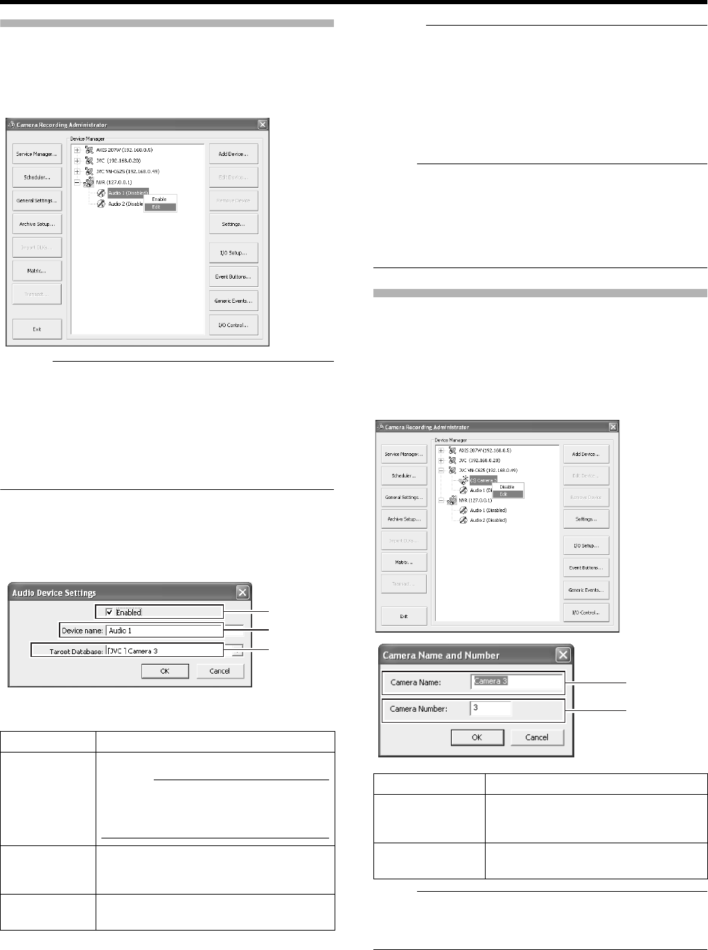
53
Specifying Audio Recording Settings
1 Select [Camera Record Setting] from the main
menu
●The [Camera Recording Administator] screen appears.
Memo :
●You can also specify audio settings using the following
operation.
AClick the [ +] mark beside the device with an audio
source
BSelect the audio source and right-click on it. Click
[Edit] and specify the settings accordingly on the
[Audio Device Settings] screen.
2 Select an audio source from [Device Manager],
and press the [Settings...] button
●The [Audio Device Settings] screen appears.
●Specify the setting for the following items.
Memo :
●The audio sound is recorded in the database of the
camera image specified in the [Target Database] item C.
●Audio sound is recorded throughout the interval when the
scheduler of the camera specified in the [Target
Database] item C is in the online mode.
●Audio signals that are input to [AUDIO IN 1/AUDIO IN 2]
on the rear panel are allocated as [Audio1] and [Audio2] in
[NVR(127.0.0.1)] on the [Device Manager].
Note :
●If the camera specified in the [Target Database] item C is
set to ADisableB, audio sound is not recorded.
●To play back the audio sound when a camera selected on
the NVR Viewer, you need to specify the audio source on
the [Settings...] screen of [Camera Record Setting]
(A Page 49).
Renaming Cameras and Assigning Camera
Numbers
1 Select a camera name and right-click on it,
followed by clicking [Edit]
●The “Camera Name and Number” editing screen
appears.
Note :
●Do not assign a camera number that is used by other
cameras. If the camera numbers overlap, the camera may
not function properly.
Item Description
AEnabled Enables/Disables the audio source.
Memo :
●Right-click on the camera or audio
source in the [Device Manager]
section to select [Disable] or [Edit].
BDevice
name
Displays the name of the audio source.
You can overwrite the existing name with
a new one.
CTarg et
Database
Enables you to specify the camera
database to record audio sound to.
A
B
C
Item Description
ACamera
Name
Displays the name of the camera. You
can overwrite the existing name with a
new one.
BCamera
Number
Enables you to specify the camera
number.
A
B
VR-N1600_J.book Page 53 Wednesday, August 8, 2007 3:32 PM
54
Basic Operation
Screen Display (Groups and Views)
Multi-view setting for multiple cameras is referred to as
[Views]. All views are placed in folders called [groups].
Memo :
●[Groups] can be private or shared.
●[Private] folder:
Views in this folder can only be accessed by the user
who created them.
●[Shared] folder:
Views in this folder can be accessed by all remote PC
users with access to the system.
(APage 54 [Creating Groups and Views])
Note :
●The default user setting is AAdministratorB.
●The Default View created by the Auto Detect feature may
change the camera placement in the view. To maintain a
fixed position, name the view and save it.
●When changing the view of the [Shared] folder, the [Save
View Group Error] screen may sometimes appear. In this
case, click the [OK] button to close the screen, log out
from the [NVR Viewer] once (A Page 111), and log in
again to repeat the procedures for changing the view.
Creating Groups and Views
䡵
Creating Groups
1 Select [Screen Setup] from the main menu
●If the [Live] or [Browse] screen is displayed, you can
also click on the [Setup] tab using the mouse.
2 Select the root folder in which you want to
create a new group
3 Click the [Create New Group] button in the
[Views] section
●A new group is created.
4 Enter a name for the new group
Screen Setup
[Screen Setup]
[Create New View] Button
[Rename] Button
[Delete] Button
[Create New Group] Button
[System Overview] Section
[Views] Section
画面表示設定
●
Main Menu
Select
[Create New Group] Button
VR-N1600_J.book Page 54 Wednesday, August 8, 2007 3:32 PM
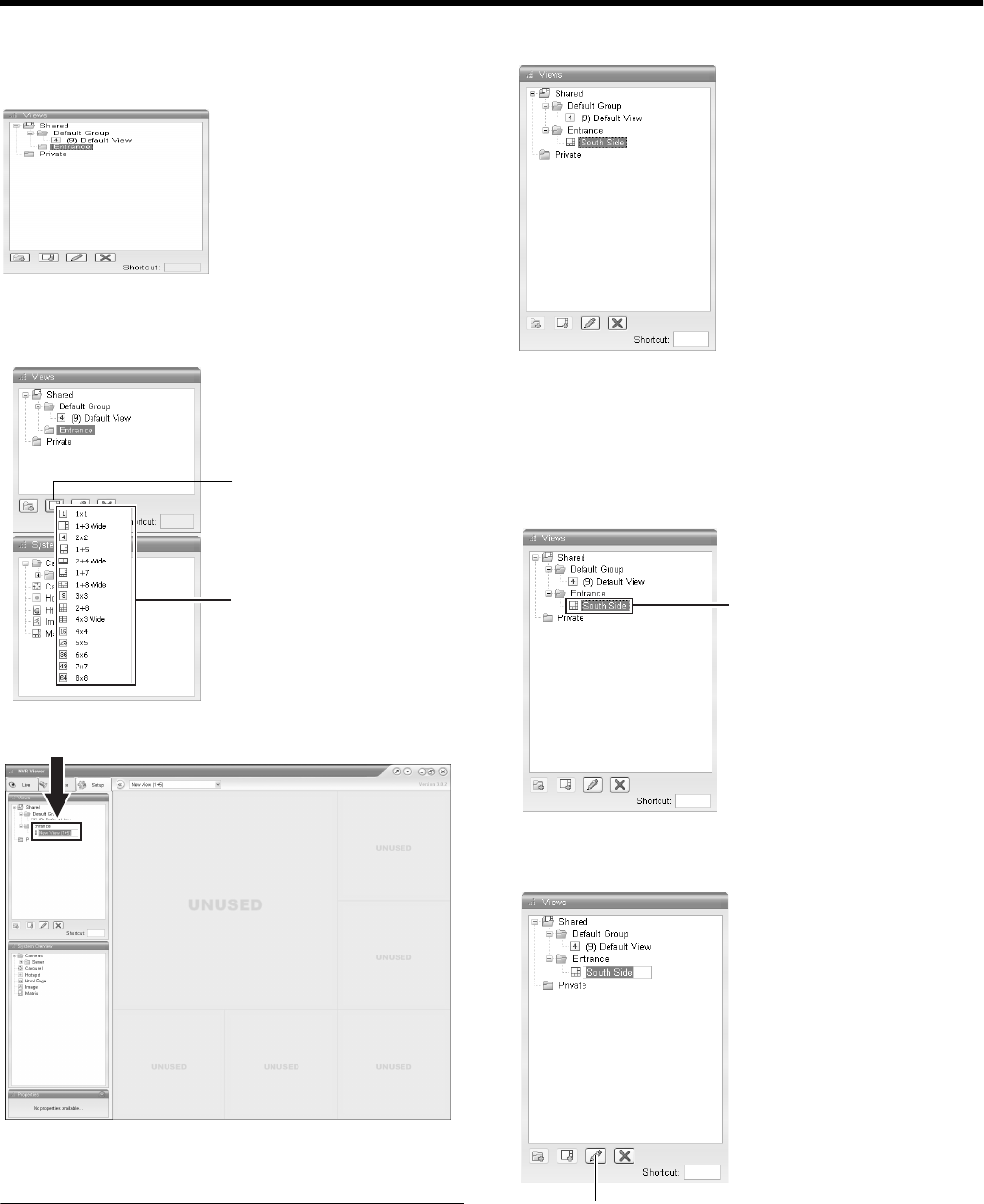
55
䡵
Creating [Views] in group
1 Select the group in which you want to create a
new view
2 Click the [Create New View] button, and select a
layout for the new view
●A new view is created under the group you selected.
Note :
●Do not display more than 17 windows at any one time.
3 Enter a name for the new view
●Next, add cameras to the view. (APage 56 [Adding
Cameras to a View])
䡵
Renaming Groups or Views
1 Select the group or view that you want to
rename in the Views section.
2 Click the [Rename] button
[Create New View] Button
View Layouts Select
[Rename] Button
VR-N1600_J.book Page 55 Wednesday, August 8, 2007 3:32 PM
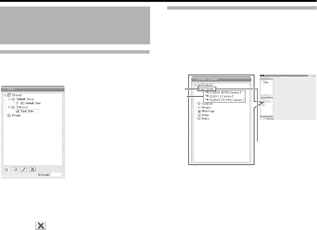
56
Basic Operation
Creating Groups and Views (Cont’d)
3 Overwriting the existing group or view name
with a new name
䡵
Deleting Groups or Views
1 Select the group(s) or view(s) that you want to
delete from the Views section.
2 Click the [Delete] button
A confirmation message appears to ask whether you want to
delete the selected group and all views inside the group, or
whether you want to delete the selected views.
Adding Cameras to a View
1 Select a view
●The layout of the selected view appears.
2 Click the [+] mark to the left of [Server] under
[System Overview]
●A list of available cameras appears.
3 Select the camera you want to add from the list,
and drag the camera name over the screen of
the view on the right
●An image from the selected camera appears together
with the camera name.
●Repeat the procedure for each camera that you want to
add.
●Images from a total of 16 cameras can be
simultaneously displayed.
Screen Setup (continued)
2
[Server]
[Screen Setup] Screen
Camera
List
VR-N1600_J.book Page 56 Wednesday, August 8, 2007 3:32 PM
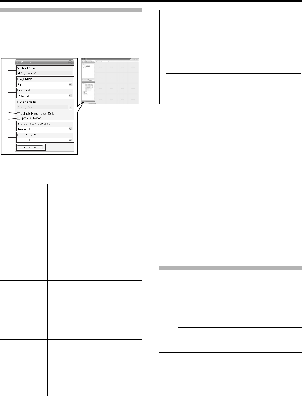
57
Adjusting Camera Settings
1 Select the camera you want to adjust on the
[Screen Setup] screen
2 Select [Properties]
3 Adjust the following camera settings
accordingly
Note :
●Set VR-N1600U/E so that the total frame rate for viewing
on all surveillance computers is 80 ips or less.
●The recording frame rate may deteriorate if you change
the picture quality. The [mage Quality] settings may affect
the recording performance. As such, use this function with
the value fixed at AFullB.
●When you drag the timeline browser using the mouse
during playback, the frame rate setting is disabled.
[Searching Recorded Image Using the Timeline Browser]
(A Page 36)
●Notification sound is not output from VR-N1600U/E during
motion detection or occurrence of an event. This function
is for use by the NVR Viewer, which is downloaded onto
the surveillance computer.
4 To adjust the settings on other cameras, repeat
Steps 2 to 3
Memo :
●To adjust the settings of all cameras at once, click the
[Apply To All] button. The new camera settings will be
applied to all cameras in the view.
Using Your Views on Different Computers
User settings, including the [Private] view, are stored in VR-
N1600U/E. In other words, you can use your [Private] views
on any surveillance computer that has this unit and the ANVR
ViewerB installed (A Page 108) by logging in with your own
user name and password.
1 Double-click the [Setup] tab on the NVR Viewer.
Note :
●Particular user rights may be required in order to access
the [Setup] tab. In this case, consult your system
administrator.
2 Select the folder you want to use in the [Views]
section
●You can create or edit views.
●Folders that cannot be edited are indicated by the
[LOCK] icons.
Item Description
ACamera
Name
Displays the name of the selected
camera. (This is a read-only field.)
Bmage Quality Enables you to adjust the image
resolution and picture quality during
viewing. Select [Full] at all times.
CFrame Rate This is the viewing frame rate.
Select [Unlimited] (default value; same
as live settings), [Medium] (25 % of
the frame rate), or [Low] (5 % of the
frame rate), depending on the frame
rate specified in [Live Settings] (A
Page 50) on the [Camera Settings]
screen.
DMaintain
Image
Aspect
Ration
If this check box is selected, images
will not be stretched to fit the size of
the display position. Images will be
displayed in the aspect ratio that they
have been recorded.
EUpdate on
Motion
If this check box is selected, the
camera’s images will only be updated
on the [Live] screen when motion is
detected.
FSound on
Event
Enables notification with a simple
sound when motion is detected while
viewing images from the camera on
the [Live] screen.
Always off Does not produce sound notification
when motion is detected.
Always on Notifies with a sound each time motion
is detected.
A
B
C
D
E
F
G
H
[Screen Setup] Screen
Item Description
GSound on
Event
Enables notification with a simple alert
sound when events related to the selected
camera occur while viewing images from
the camera on the [Live] screen.
To use this feature, you need to configure
the event notification setting. (A Page 90)
Always off Does not output sound alert when an
event related to the camera occurs.
Always on Outputs a sound alert each time an event
related to the camera occurs.
HApply To
All
Press this button to apply the new settings
to all cameras.
VR-N1600_J.book Page 57 Wednesday, August 8, 2007 3:32 PM
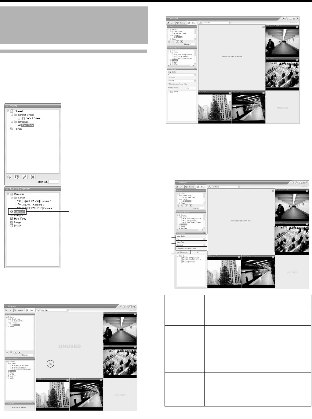
58
Basic Operation
Adding a Carousel
You can use the carousel feature to display images from
multiple cameras in sequence in a single view position. Also,
you can set the time interval for switching the camera to view.
1 Displaying the [Screen Setup] Screen
2 Click and drag the [Carousel] icon in the
[System Overview] section to the position that
you want to set in the view
3 Release the mouse button at the position
4 Select the preset carousel position and specify
its properties in the [Properties] section
●Begin by selecting the cameras to include in the
carousel. You can also select all cameras on a server
at once by selecting the check box next to the [Server]
icon.
Screen Setup (continued)
[Carousel]
[NVR] Camera3 [NVR] Camera4
Item Description
Amage
Quality
Enables you to adjust the image
resolution and picture quality during
viewing. Select AFullB at all times.
BFrame
Rate
This is the viewing frame rate.
Select [Unlimited] (default value; same as
live settings), [Medium] (25 % of the frame
rate), or [Low] (5 % of the frame rate),
depending on the frame rate specified in
[Live Settings] (A Page 50) on the
[Camera Settings] screen.
CMaintain
Image
Aspect
Ration
If this check box is selected, images will
not be stretched to fit the size of the
display position. Images will be displayed
in the aspect ratio that they have been
recorded.
[NVR] Camera3 [NVR] Camera4
[NVR] Camera2
[NVR] Camera3 [NVR] Camera4
[NVR]Camera1
[NVR] Camera2
A
B
C
VR-N1600_J.book Page 58 Wednesday, August 8, 2007 3:32 PM
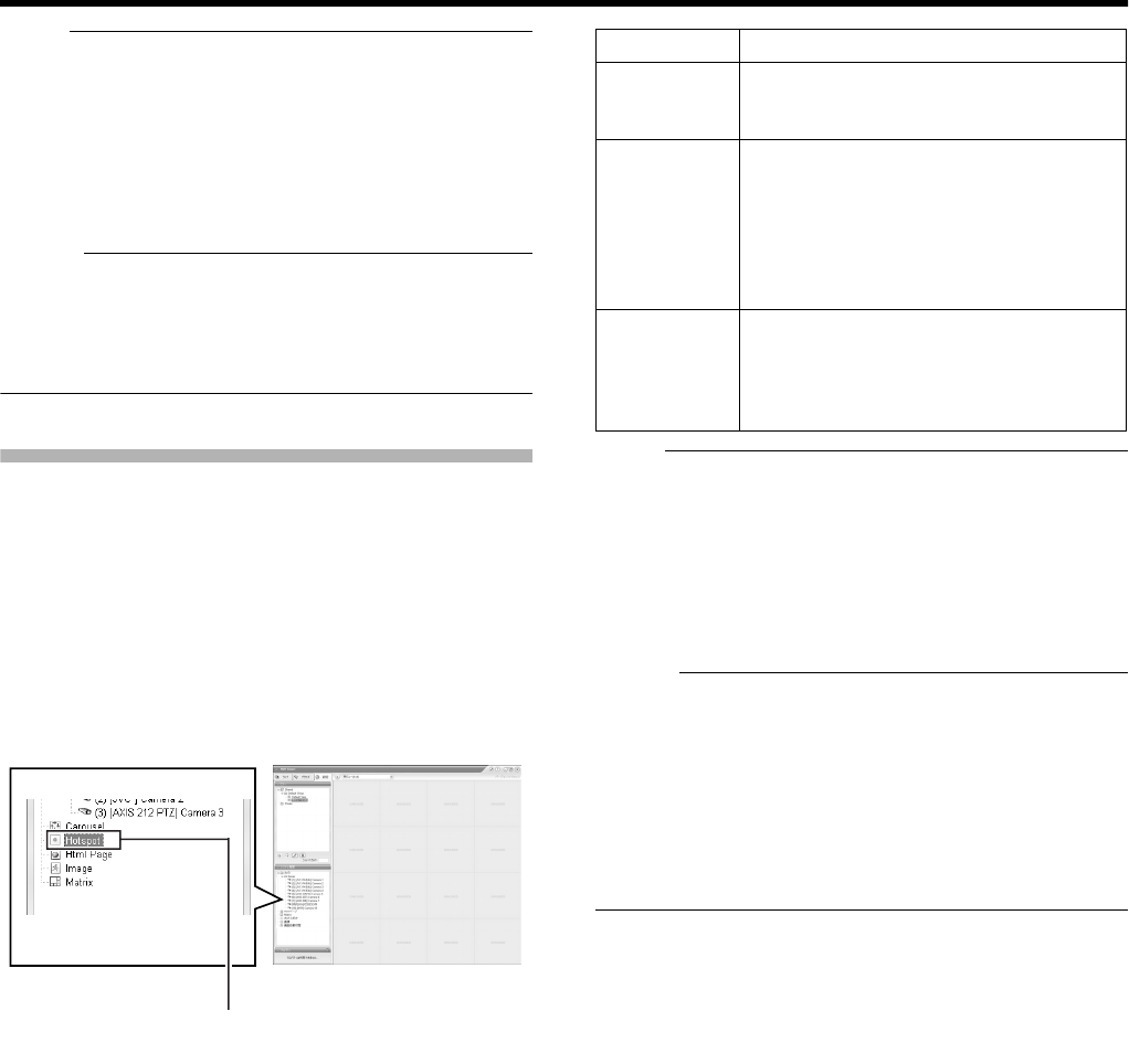
59
Note :
●The recording frame rate may deteriorate if you change
the picture quality. The [mage Quality] settings may affect
the recording performance. As such, use this function with
the value fixed at AFullB.
●When you drag the timeline browser using the mouse
during playback, the frame rate setting is ADisabledB.
[Searching Recorded Image Using the Timeline Browser]
(A Page 36)
Memo :
●The green border indicates that the position is used for the
carousel feature.
●The sequence in which cameras appear in the carousel is
automatically determined by their names. The cameras
appear recurrently in alphabetical order.
Adding Hot Spots (Enlarged Images)
The selected camera within the view is displayed in the hot
spot designated position. Setting the hot spot in a larger
position, such as in [1] of the [1+7] view, displays an enlarged
image when the hot spot is selected.
1 Displaying the [Screen Setup] Screen
2 Click and drag the [Hotspot] icon in the [System
Overview] section to the position that you want
to set in the [Views]
3 Release the mouse button at the position
4 Select the preset position in [Hotspot] and
specify its properties in the [Properties] section
Note :
●The recording frame rate may deteriorate if you change
the picture quality. The [mage Quality] settings may affect
the recording performance. As such, use this function with
the value fixed at AFullB.
●When you drag the timeline browser using the mouse
during playback, the frame rate setting is ADisabledB.
[Searching Recorded Image Using the Timeline Browser]
(A Page 36)
Memo :
●Using the [Hotspot] function enables you to use a low
frame rate for other cameras and a high frame rate for the
hot spot.
●The orange border indicates that the position is used for a
hotspot.
●When the hot spot is set in multiple views and the view is
switched, the camera image displayed in the view before
switching continues to be displayed in the hot spot window
in the view after switching.
[Hotspot]
[Screen Setup]
Item Description
Amage
Quality
Enables you to adjust the image
resolution and picture quality during
viewing. Select AFullB at all times.
BFrame
Rate
This is the viewing frame rate.
Select [Unlimited] (default value; same as
live settings), [Medium] (25 % of the frame
rate), or [Low] (5 % of the frame rate),
depending on the frame rate specified in
[Live Settings] (A Page 50) on the
[Camera Settings] screen.
CMaintain
Image
Aspect
Ration
If this check box is selected, images will
not be stretched to fit the size of the
display position. Images will be displayed
in the aspect ratio that they have been
recorded.
VR-N1600_J.book Page 59 Wednesday, August 8, 2007 3:32 PM
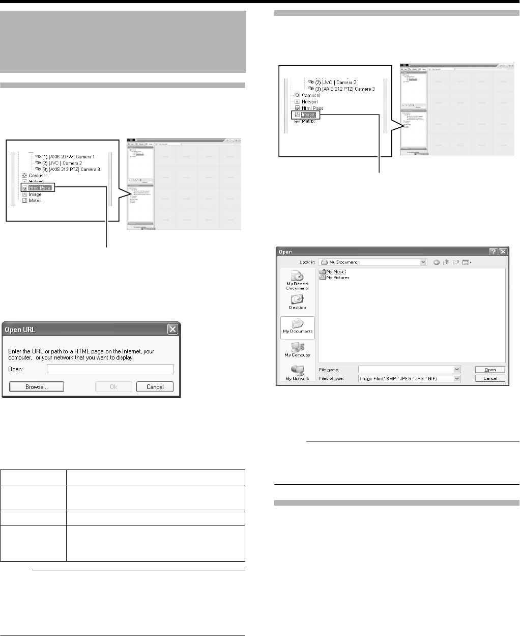
60
Basic Operation
Using the [Html Page]
1 Click [Html Page] under [System Overview]
2 Drag and drop at the required position using the
mouse.
The [Open URL] screen appears.
3 Type in the URL and click [OK]
4 Select [Html Page] under [Views], and specify
the properties in the [Properties] section
Note :
●Pages containing such content as ActiveX and Flash will
not be supported.
●Pages containing such content as ActiveX and Flash will
not be supported.
●Note that some links may involve security issues.
Using Still Images (GIF files, JPEG files, etc.)
1 Click [Image] under [System Overview]
2 Drag and drop at the required position using the
mouse.
●The [Open] screen appears.
3 Select the required image file
Note :
●When connected to a surveillance computer, still images
that are set on a different computer are not displayed.
●Still images cannot be added to VR-N1600U/E.
Adding Matrix Content
Select this option to use the Milestone XProtect Matrix
feature.
For details, refer to the Smart Client 3.0 User’s Manual
provided by Milestone Systems.
(http://www.milestonesys.com/?cid=265)
Screen Setup (continued)
Item Description
URL Click the [New...] button to specify a new
URL.
Scaling Select the display size of the HTML page.
Enable HTML
scripting
Select this check box to specify HTML
files that contain navigation or trigger
functions.
[Html Page]
[Screen Setup] Screen
[Image]
[Screen Setup] Screen
[Open] Screen
VR-N1600_J.book Page 60 Wednesday, August 8, 2007 3:32 PM
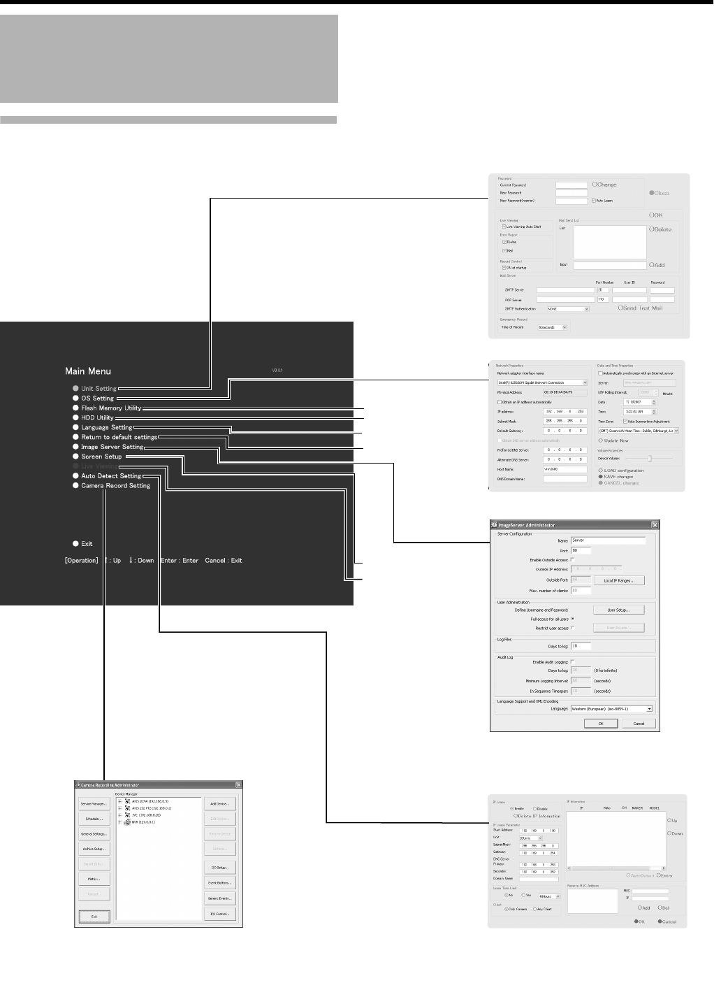
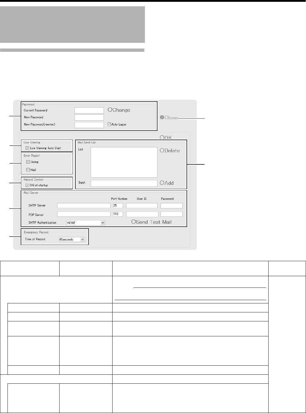
62
Applications
Unit Setting
Unit Setting enables you to specify settings related to the VR-N1600U/E unit, including account configuration, error recovery, and
serial port configuration.
Main Menu List (continued)
G
H
A
B
C
D
E
F
Item Preset Values Description Reference
Page
APassword Enables you to specify the login password for VR-N1600U/E.
Note :
●Specify the password using numeric characters only.
A Page 23
Current Password ^To change to a new password, enter the [Current Password].
New Password ^Enter a new password.
New
Password(reenter)
^Enter the new password again for confirmation, and click
[Change] to enable the password change.
Auto Logon 䢇Select check
box
Do not select
check box
To log in automatically after turning on the power of this unit,
select the [Auto Logon] check box.
Change ^Executes the password change.
BLive viewing
Live viewing Auto
Start
䢇Select check
box
Do not select
check box
Select this check box to display live images automatically when
the system starts up.
VR-N1600_J.book Page 62 Wednesday, August 8, 2007 3:32 PM
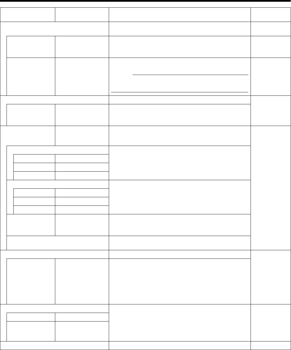
63
Item Preset Values Description Reference
Page
CError Report Enables you to select how you want to be notified when an
error is detected in the system.
^
Dialog 䢇Select check box
Do not select
check box
Select [Dialog] to display a warning dialog on the screen. A Page 126
Mail 䢇Select check box
Do not select
check box
Select [Mail] to receive an e-mail notification on any
abnormality at the preset e-mail address.
Memo :
●For details on errors, refer to the actions to take when the
[WARNING] indicator lights up. (A Page 126)
^
DRecord Control ^
ON at startup 䢇Select check box
Do not select
check box
Select this check box to turn on the recording control mode
when the system starts up.
EMail Server ^Enables you to configure the necessary information on the
mail server to be used if you have selected AMailB in the
[Error Report] item C.
^
SMTP Server Setting for the outgoing mail server.
Port Number 䢇25
User ID ^
Password ^
POP Server Setting for the incoming mail server.
Port Number 䢇110
User ID ^
Password ^
SMTP
Authentication
䢇NONE
Authentication
POP before SMTP
Enables you to select the method of user authentication
when sending out a mail. For queries on the settings, consult
your system administrator.
Send Test Mail Click to send out a test mail to the address specified in the
[Mail Send List] item G.
FEmergency Record A Page 46
Time of Record NONE
30seconds
䢇60seconds
5minutes
10minutes
20minutes
Continue
Select the duration of emergency recording, which starts
recording of all channels when a signal is input to the
[EMERGENCY] terminal on the rear panel.
Select AContinueB to continue recording until it is stopped
manually on the front panel.
GMail Send List Enables you to specify the mail recipient if you have selected
AMailB in the [Error Report] item C. To add a new recipient,
type the e-mail address in the entry field and click the [Add]
button. To remove an e-mail address from the notification list,
select the required e-mail address in the [List] and click
[Delete].
^
List ^
Input ^
HClose Closes the Unit Setting screen. ^
VR-N1600_J.book Page 63 Wednesday, August 8, 2007 3:32 PM
64
Applications
OS Setting
Enables you to specify settings related to the OS, including network, time, and volume settings.
You may need to reboot your computer depending on the settings.
䡵
Network Adapter
This section enables you to specify settings such as the IP address of VR-N1600U/E. The camera network and Intranet of VR-
N1600U/E are configured with a different IP address. The default address for the camera network is (192.168.1.253), and that
for the Intranet is (192.168.1.253).
There is a common host name for all adapters.
䢇When specifying LAN1 (camera network) settings
Main Menu List (continued)
C
B
A
D
E
F
Item Preset Values Description
ANetwork adapter
interface name
Intel姞 82566DM
Gigabit Network
Settings when you are using LAN1 (camera network).
Obtain an IP
address
automatically
Select check box
䢇Do not select
check box
Memo :
●To specify an IP address other than the default value, consult your system
administrator.
●If the host name is changed, you need to specify Windows user in [User
Administration] under [Image Server Setting]. (A Page 104)
●Do not set the default gateway for both the camera network and Intranet
on the [OS Setting] screen. Doing so may cause the system to
malfunction.
IP address 䢇192.168.1.253
Subnet Mask 䢇255.255.255.0
Default Gateway 䢇0.0.0.0
Perferred DNS
Server
䢇0.0.0.0
Alternate DNS
Server
䢇0.0.0.0
Host Name 䢇vr-n1600
DNS Domain
Name
䢇0.0.0.0
VR-N1600_J.book Page 64 Wednesday, August 8, 2007 3:32 PM
65
䢇When specifying LAN2 (Intranet) settings
䢇Other Settings
Item Preset Values Description
A
Network adapter
interface name
(continued)
Intel姠8225xER PCI
Adapter
Settings when you are using LAN2 (Intranet).
Obtain an IP
address
automatically
Select check box
䢇Do not select
check box
Memo :
●To specify an IP address other than the default value, consult your
system administrator.
●If the host name is changed, you need to specify Windows user in
[User Administration] under [Image Server Setting]. (A Page 104)
●Do not set the default gateway for both the camera network and
Intranet on the [OS Setting] screen. Doing so may cause the system to
malfunction.
IP address 䢇192.168.1.253
Subnet Mask 䢇255.255.255.0
Default Gateway 䢇192.168.1.254
Perferred DNS
Server
䢇0.0.0.0
Alternate DNS
Server
䢇0.0.0.0
Host Name 䢇vr-n1600
DNS Domain Name ^
Item Preset Values Description
BDay and Time Properties To synchronize the time with the Internet time server or to specify the
date and time manually, click [Update Now].
Automatically
synchronize with an
Internet server
Select check box
䢇Do not select
check box
Select this check box to synchronize the time with the Internet time
server.
Note :
●You cannot specify the date and time manually when this box is
selected. The settings in the boxes cannot be changed.
●The date and time properties are not enabled until you have clicked
the [Update Now] button.
●Changing the time setting may prevent normal playback of recordings
made at the same time as a result.
●Changing the ATimeB field of the time setting when operations are in
progress may prevent normal display of live images. In this case,
reboot VR-N1600U/E.
Server ^Enter the address of the Internet time server.
NTP Polling Interval ^For specifying the time interval (in minutes) for synchronizing with the
Internet time server.
Date ^Enter this field when you are specifying the date manually.
Time
Time Zone 䢇VR-N1600U :
(GMT-05:00)
Eastern Time
䢇VR-N1600E :
(GMT) Greenwich
Mean Time
For specifying the time zone.[Auto Summertime Adjustment] is checked.
Note :
●Make sure that the date and time that you specify does not overlap
with any previous recorded data.
●If the specified time zone is incorrect, the system may not run at the
correct time after synchronizing with the Internet time server.
●When changes are made to the time zone, press and hold the
[FUNCTION] button, and press the [LIVE/BROWSE] button at the
same time to reboot the NVR Viewer.
CVolume Properties
Device Volume 䢇Center position Adjust the volume using the slider bar.
DLOAD configuration ^Reads the preset configuration files and displays them on the screen.
ESAVE changes ^Exits after entries and the selected content are configured to the system.
Manual update of time is disabled. To update the time manually, go to the
[Day and Time Properties] item C.
FCANCEL changes ^Exits without saving all entries and selected settings.
VR-N1600_J.book Page 65 Wednesday, August 8, 2007 3:32 PM
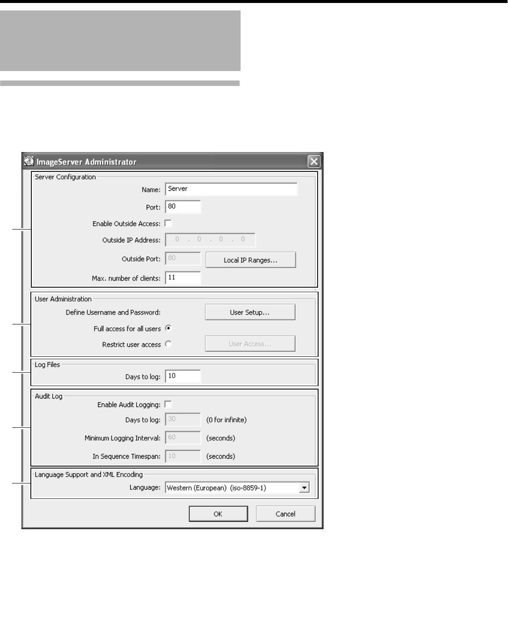
66
Applications
Image Server Setting
This section enables you to specify settings for connecting this unit to a computer, and for displaying the [Live] and [Browse]
screens.
The distribution settings are also applied to operation on the [Live], [Browse], and [Screen Setup] screens of VR-N1600U/E.
Main Menu List (continued)
A
B
C
D
E
VR-N1600_J.book Page 66 Wednesday, August 8, 2007 3:32 PM
67
Item Preset Values Description
AServer Configuration Enables you to specify the server name, port number, and details on external
access to the server.
Name 䢇Server For specifying the server name.
Port 䢇80 For specifying the port number to use for the server.
Enable Outside IP
Address
Select check box
䢇Do not select
check box
Select this check box to enable access to VR-N1600U/E from a surveillance
computer connected to the Internet via the router or firewall.
If you have selected this option, specify the global IP address in the [IP
address] column for the Internet router or firewall, and the port number in the
[Port] column for access to the Internet by the surveillance computer.
You have to configure an appropriate port forwarding on the router or firewall
to allow access by a surveillance computer that is connected to the Internet.
For details, refer to the “Instruction Manual” of the respective devices.
Outside IP
address
^For specifying the global IP address when connecting to VR-N1600U/E via
the Internet.
Port ^For specifying the port number to use when connecting to VR-N1600U/E via
the Internet.
Local IP Ranges... ^Settings for using the Master/Slave feature by Milestone Systems.
For specifying the beginning of the IP address range in the left field on the
screen, and the end of the IP address range in the right field. Click the [Add]
button.
You may define as many local IP address ranges as required.
Memo :
●If necessary, you may also specify only one IP address.
(Example: 192.168.10.1to192.168.10.1)
●For details, refer to the Enterprise 6.0 Administrator’s Manual provided by
Milestone Systems.
(http://www.milestonesys.com/?cid=265)
Max,number of
clients
䢇11 For specifying the maximum number of NVR Viewer users allowed for
connection at any one time. The number of users also includes the use of
the [NVR Viewer] on the [Live] and [Browse] screens of VR-N1600U/E. Do
not set a number of larger than 11.
BUser
Administration
This section describes procedures to configure user accounts and rights.
User Setup... ^Click this button to display the [User Administration] screen for setting the
[User] and [Password]. You can add new users in two ways: (APage 104
[User Settings])
Memo :
●After adding a new user, a small square appears to the top left of the icon
on the [User Administration] screen. You can distinguish between [Add
Basic User...] and [Add Windows User...] using this mark when the same
user name is registered with both.
User vr-n1600 Type:Basic user
Password: Nil
Administrator Type: Windows or Active Directory user or Active Director User
Password:vr-n1600
Add Basic
User...
^You can create a dedicated user account for the surveillance system through
authentication of the user name and password.
VR-N1600_J.book Page 67 Wednesday, August 8, 2007 3:32 PM
68
Applications
Image Server Setting (continued)
Main Menu List (continued)
Item Preset Values Description
BUser Administration (continued)
User Setup... (continued)
Add Windows
User...
^Do not select this option. For details, consult your system administrator.
Note :
●When the host name in the OS settings is changed, enter [Administrator]
in [Enter the object names to select] on the [Serect Users or Groups]
screen, and click the [Advanced...] button. Next, click the [OK] button.
●Windows users need to define a Windows user for each host name
specified in [Host Name] in [OS Setting]. (A Page 64)
As the user’s host name is not displayed on the [User Administration]
screen, it is recommended that you delete the Windows user and add
again if you have changed the host name. (A Page 104)
Delete ^Deletes a preset user.
Select the user to delete from the [Current isers/groups] list, and click the
[Delete] button. The user that has been deleted from the list is no longer able
to login to NVR Viewer.
Change
password...
^Enables you to edit a preset user name and password.
Select the user to edit from the [Current isers/groups] list, and click the
[Change password...] button.
Define Username
and Password
䢇Full access for all
users
Restrict user access
[Full access for all users]:
Select this option to grant all users access to all NVR Viewer features and
cameras.
[Restrict user access]:
Select this option to restrict users’ access. Then click the [User Access...]
button to define access rights for each user.
Memo :
●For details on user authority, refer to [Defining User Rights] (A Page 104).
VR-N1600_J.book Page 68 Wednesday, August 8, 2007 3:32 PM
69
Item Preset Values Description
CLog Files Log information may be required for diagnosing troubles.
Days to log 䢇10 For specifying the number of days for storing the event log in
the [Image Server Setting].
DAudit Log Enables you to configure log file settings related to client
computer users.
Enable Audit
Logging
Select check box
䢇Do not select check box
Days to log 䢇30 For specifying the number of days for storing the audit log files.
Minimum Logging
Interval
^For specifying the minimum time interval for acquiring logs.
In Sequence
Timespan
^For specifying the maximum viewing time interval that is to be
considered as the same sequence.
ELanguage Support and XML Encoding Enables you to select the available languages. Select a
language (local character set) for the camera names, user
names, and passwords. Select the language of your choice.
Language Traditional Chinese (Big5)
Japanese (euc-jp)
Simplified Chinese (GB2312)
Central,Eastern European (ibm852)
Cyrillic (ibm866)
䢇Western(European)(iso-8859-1)
Thai(iso-8859-11)
Central,Eastern European (iso-8859-2)
Southern European (latin) (iso-8859-3)
Baltic (iso-8859-4)
Cyrillic (iso-8859-5)
Arabic (iso-8859-6)
Greek (iso-8859-7)
Hebrew (iso-8859-8)
Turkish (iso-8859-9)
Korean (ks_c_5601-1987)
Japanese (shift-jis)
Universal(UTF7) (utf-7)
Universal(UTF8) (utf-8)
Central,Eastern European (windows-1250)
Cyrillic (windows-1251)
Western(European) (windows-1252)
Greek (windows-1253)
Hebrew (windows-1255)
Arabic (windows-1256)
Baltic (windows-1257)
Vietnamese (windows-1258)
Thai (windows-874)
Japanese (_iso-2022-jp$ESC)
VR-N1600_J.book Page 69 Wednesday, August 8, 2007 3:32 PM
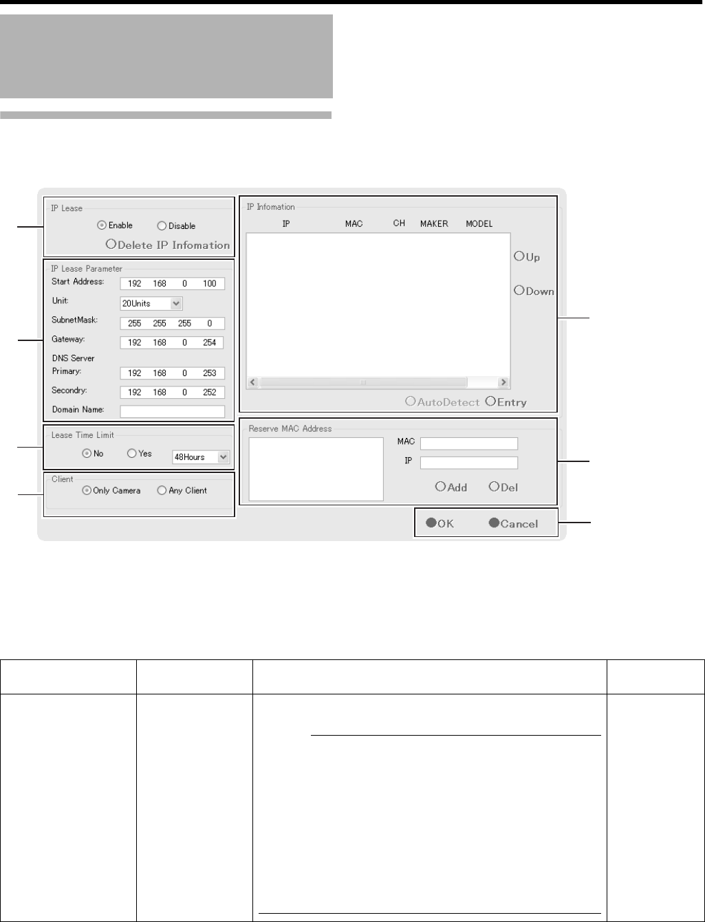
70
Applications
Auto Detect Setting
This section enables you to assign an IP address to each camera and configure various auto detect settings.
For procedures on using the Auto Detect feature, refer to [Auto Detect Settings] (A Page 100).
Main Menu List (continued)
A
B
C
E
D
F
G
Item Preset Values Description Reference
Page
AIP Lease 䢇Enable
Disable
For configuring the function to assign IP addresses to each
network camera.
Memo :
●In order to assign an IP address of the network camera
using the IP Lease feature, you need to enable the DHCP of
the network camera. For procedures to enable the DHCP of
the network camera, refer to the [INSTRUCRTIONS] of the
network camera.
●If a network uses a multiple number of VR-N1600U/E units,
enable the [IP Lease] only for one unit. Select ADisableB if a
DHCP server is operating on the same network. When the
[IP Lease] is enabled for two or more devices at the same
time, the IP address may change to a static address, and
cause malfunction of the cameras.
A Page 100
VR-N1600_J.book Page 70 Wednesday, August 8, 2007 3:32 PM
71
Item Preset Values Description Reference
Page
BIP Lease Parameter ^
Start Address 䢇80 For specifying the first IP address to be assigned to the
cameras.
Unit 䢇20Units
1Unit to 99Units
For selecting the number of IP addresses to be assigned to
the cameras. The selected number of IP addresses will be
assigned starting from the first IP address.
Subnet Mask ^For specifying the subnet mask for the cameras.
Gateway ^For specifying the gateway for the cameras.
DNS Server
Primary 䢇
192.168.0.253
For specifying the primary DNS for the cameras.
Secondry 䢇
192.168.0.252
For specifying the secondary DNS for the cameras.
Domain Name ^For specifying the domain name for the cameras.
CLease Time Limit 䢇No
Ye s
For specifying the valid period of the IP address assigned to
the cameras.
If AYe s B is selected, you can set the lease time in units of
hours. (Setting value: 1 hour to 99 hours)
^
DClient 䢇Only Camera
Any Client
For selecting whether to apply restrictions on the device when
assigning the IP address. If AOnly CameraB is selected, IP
address will only be assigned to the corresponding camera. If
AAny ClientB is selected, IP address will be assigned to all
devices.
^
EIP Information ^The [IP Information] list contains information on the IP
address of the automatically detected camera, MAC address,
number of video CH, manufacturer, and model.
Click [Auto Detect] to start auto detect and display the result.
The camera at the top of the list is used with priority.
You can sort the order of the detected cameras by clicking the
Sort button.
The different types of sort buttons include the [IP], [MAC],
[CH], [MAKER], and [MODEL] sort buttons.
After selecting the detected camera, click the [Up] or [Down]
button to alter the order of the cameras.
Deselect the check box of any camera that you are not using.
Memo :
●When multicast packets are configured such that they do
not pass through the network equipment, such as a
switching hub, the Auto Detect of the camera may not
function properly.
A Page 100
A Page 14
FReserve MAC
Address
^Configure the [Reserve MAC Address] if you want to assign a
specific IP address to the cameras. A specific IP address is
always mapped to a MAC address. Enter a value in the [MAC]
and [IP] fields, and click [Add] to set the addresses. To cancel
the setting, select a displayed MAC and IP address and click
[Del].
^
GOK/Cancel ^Clicking this button closes the setup screen and starts the
assignment of IP addresses.
^
VR-N1600_J.book Page 71 Wednesday, August 8, 2007 3:32 PM

73
Item Description Reference
Page
AService Manager... Pressing the [Service Manager...] button opens a small [Service Manager]
screen, which enables you to pause/resume the ARecording ServerA recording
program.
Use this feature when you need to pause the program, such as when configuring
PTZ cameras.
A Page 78
BScheduler... Displays the [Scheduler...] screen. A Page 47
CGeneral Settings... Displays the [General Settings] screen. A Page 93
DArchive Setup... Displays the [Archive Setup] screen. A Page 95
EImport DLKs... Not used. ^
FMatrix... Settings for using the Milestone XProtect Matrix by Milestone Systems.
For details, refer to the Milestone XProtect Matrix manual provided by Milestone
Systems.
(http://www.milestonesys.com/?cid=265)
^
GTransact... Not used. ^
HExit Closes the [Camera Recording Administator] screen. ^
IDevice Manager Displays the list of all added devices and connected cameras, which provides
you with a summarized view of the surveillance system.
^
JAdd Device... Starts the [Device Setup Wizard]. A Page 74
KEdit Device... Displays the [Edit device settings] screen. A Page 75
LRemove Device For deleting a device selected in the [Device Manager] section I.
Note :
●If you remove the device, you will not be able to view recorded images. Do not
delete devices that are needed to view recorded images subsequently. In this
case, select ADisabledB under [Camera Monitor Setup] (A Page 50) on the
[Camera Settings] screen. To view recorded images, cancel ADisabledB in
[Camera Monitor Setup].
^
MSettings... For specifying the recording settings for a selected camera or settings for a
selected audio device.
A Page 49
A Page 53
NI/O Setup... Displays the [I/O Setup] screen. A Page 83
OEvent Buttons... Displays the [Event Buttons] screen. A Page 87
PGeneric Events... Displays the [Generic Events] screen. A Page 88
QI/O Control... Displays the [I/O Control] screen. A Page 90
VR-N1600_J.book Page 73 Wednesday, August 8, 2007 3:32 PM
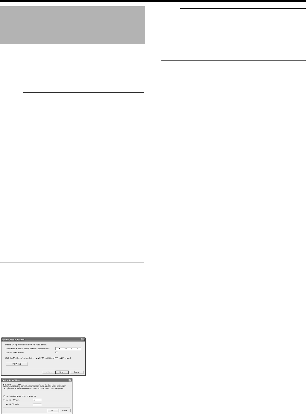
74
Applications
To specify settings on camera connection, you first need to
add the required devices, such as network cameras or
network encoders (IP video servers), to the system. Devices
have their own IP addresses and host names. The system
identifies the devices based on their IP address or host
name.
Memo :
●Even though each device is managed using a unique IP
address or host name, in cases such as when multiple
analog cameras are connected to a network encoder (IP
video server), a multiple number of cameras may be
connected to a single device and thus share the same IP
address or host name. Although several cameras are
connected to one device in this case, this unit manages
the cameras on an individual basis.
●In addition to the network camera and network encoder
(IP video server), you can also add a number of dedicated
I/O (input/output) devices to the system. You can
configure and use the event settings for the I/O devices in
the same way as cameras.
●When a device is added to the system, it is listed on the
[Camera Recording Administator] screen. To add a new
device, follow the procedure below. Firstly, configure the
IP address and password of the device according to
instructions in the camera manual.
●You cannot add a camera for which there is user access
restriction. For details on access restrictions, refer to the
camera’s “Instruction Manual”.
●If the camera is registered with the user access restriction
set to ON, the camera is registered with access restriction
and unable to display live images unless the settings are
changed.
1 Select [Camera Record Setting] from the main
menu
2 Click [Add Device...]
●The [Device Setup Wizard] screen appears.
3 Enter the IP address or DNS host name that can
be identified by the system
●To enter the DNS host name, select the [Use DNS host
name] check box and click [Next].
Note :
●The Ahttp port 80B followed by AFTP port 21B are used by
default. To use a different port, click [Port Setup] and
specify the required port numbers. You may need to
specify a different port if the device is located behind a
NAT router or firewall. In this case, configure the router or
firewall so that it maps the ports and IP address used by
the device.
4 If an administrator password is specified for the
device, enter the password
●The password is usually set to [root] or [admin].
●Click [Next] without specifying [Autodetect Device].
5 Enter a unique name for the device that has
been detected
●The device is listed in the [Device Manager].
6 Click [Finish]
●To view the list of cameras connected to the device,
click the plus (+) sign to the left of the device name.
Memo :
●The camera names are set as [Camera1], [Camera2],
[Camera3], [Camera4],…etc. by default. To change the
name of a camera, select the device and click the camera
name.
●The camera number increases in sequence as new
cameras are added.
●Registration of the cameras can also be performed
automatically. (APage 100 [Auto Detect Settings])
Adding Cameras
[Device Setup Wizard] Screen
VR-N1600_J.book Page 74 Wednesday, August 8, 2007 3:32 PM
75
This section describe the procedures to edit the settings of
added devices.
1 Select [Camera Record Setting] from the main
menu
●The [Camera Recording Administator] screen appears.
2 Select a device in the [Device Manager] section,
and click the [Edit Device...] button
●The [Device Setup Wizard] screen appears.
●The following items can be specified.
Editing Device Settings
[Camera Recording Administator] Screen
A
B
C
[Edit device settings] Screen
Item Description
AIdentify Video Device
Device Type For selecting the type of device from the
list.
Detect
Device
Click this button to enable automatic
detection of the device type and serial
number.
Device Name Name used to identify the device. You
cannot assign the same name to
multiple devices.
Camera
Settings...
Displays the camera setting screen.
Device Serial
Number
Serial number of the device. The 12-
character MAC address of the device is
normally used.
BNetwork Settings for Video Device
IP address IP address or DNS host name of the
device.
Use DNS
host name
Select this check box to identify the
device using the DNS host name
instead of its IP address.
Default Http
Port
Select this check box to allow HTTP
traffic to the device through the default
port (Port 80).
To use another port, deselect the check
box and specify the port number in the
field to the left of the check box.
Default Ftp
Port
Select this check box to allow FTP traffic
to the device through the default port
(Port 21).
To use another port, deselect the check
box and specify the port number in the
field to the left of the check box.
Root
Password
Enter the password for logging into the
device using the root account (also
known as Admin or Administrator
account).
Memo :
●If you are using VN-C625/VN-C655,
an error message does not appear if
you have entered a wrong password
and clicked OK, but access to the
camera may fail, such as not being
able to view the live images.
COK/Cancel Confirms or cancels the settings.
VR-N1600_J.book Page 75 Wednesday, August 8, 2007 3:32 PM
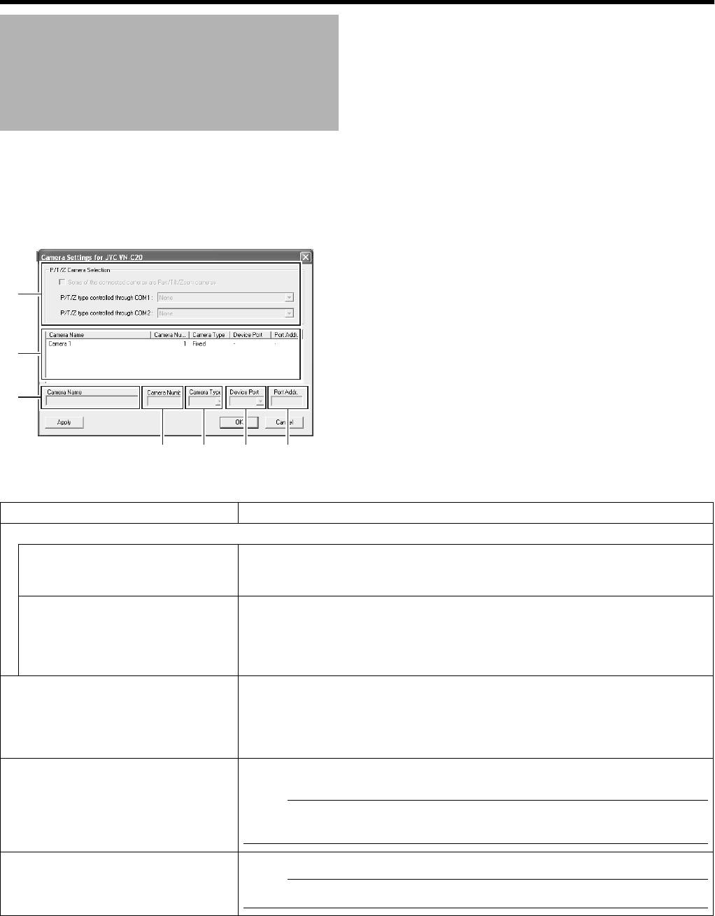
76
Applications
The [Camera Settings] screen enables you to specify of the information on cameras. The number of configurable parameters
available on the [Camera Settings] screen may be limited if the camera does not come with the PTZ features or if the device
connected to the network encoder (IP video server) is not a camera.
To display the [Camera Settings] screen, click the [Camera Settings...] button on the [Edit device settings] screen.
PTZ Camera Settings
(COM1/COM2)
Item Description
APTZ Camera Section
Some of the connected cameras
are Pna/Tilt/Zoom cameras
Select this check box if any of the cameras connected to the network encoder (IP
video server) is a PTZ camera.
If the PTZ features are not available on the device, the check box is disabled.
P/T/Z type controlled through
COM1/COM2
For selecting a control method that conforms with the PTZ camera from the list if the
PTZ camera is controlled through the COM1 or COM2 port of the network encoder
(IP video server).
If all the PTZ cameras are not controlled through the COM1 or COM2 port, select
ANoneB.
BCamera List On the camera list, the camera numbers on the device are listed in sequence.
For example, the top line corresponds to camera number 1, and the second line
corresponds to camera number 2, and so on.
To change the camera settings, select a camera number from the list, specify the
required information in the following fields, and click the [Apply] button.
CCamera Name Name used to identify the selected camera. Do not assign a camera name that is
used by other devices.
Note :
●The “Camera Name” is not the name specified for the camera unit, but for
identifying the camera on VR-N1600U/E.
DCamera Number For specifying the camera number.
Note :
●Do not assign a camera number that is used by other cameras.
A
B
C
D E F G
[Camera Settings]
Screen
VR-N1600_J.book Page 76 Wednesday, August 8, 2007 3:32 PM

77
ECamera Type For specifying whether the camera corresponding to the selected number is [Fixed]
or [Moveable].
Fixed :Fixed Camera
Moveable :PTZ Camera
FDevice Port This option is enabled only if AMoveableB is selected in the [Camera Type] item E.
For specifying which control port on the network encoder (IP video server) to use for
controlling the PTZ features.
GPort Addr. This option is enabled only if AMoveableB is selected in the [Camera Type] item E.
Use this option to specify the port address of the camera. The port address is
usually set to A0B or A1B.
If the PTZ cameras are serially connected, they are identified by their the port
addresses. Refer to the camera’s [INSTRUCRTIONS] for the recommended
settings.
VR-N1600_J.book Page 77 Wednesday, August 8, 2007 3:32 PM
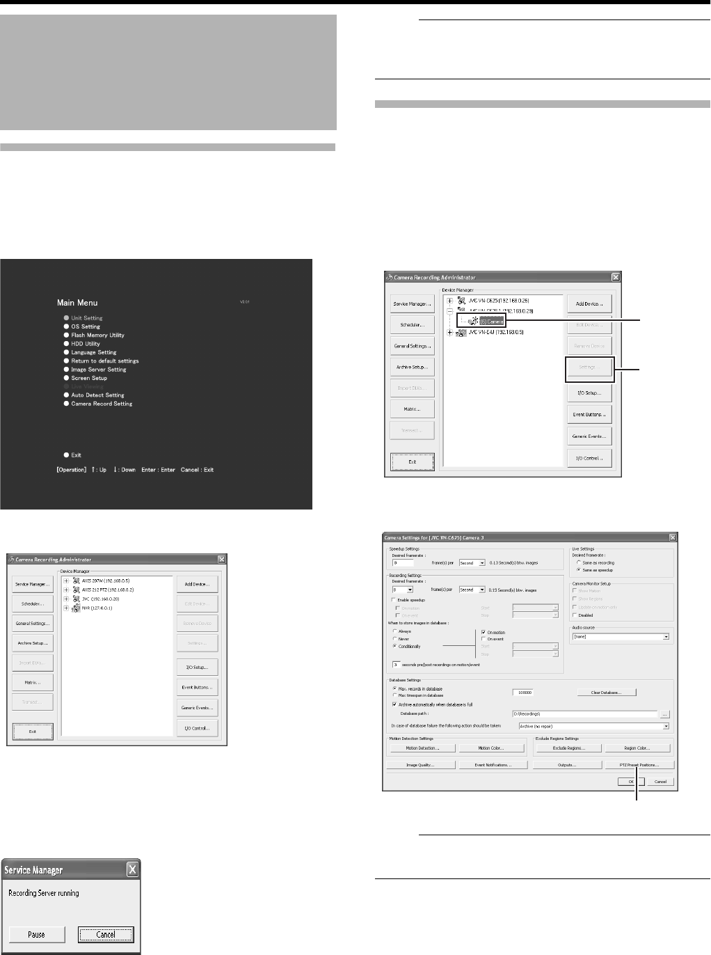
78
Applications
Stopping the Recording Server
Stop the recording server before defining the PTZ camera
settings.
1 Select [Camera Record Setting] from the main
menu
2 Click the [Service Manager...] button
The [Service Manager] screen appears.
3 Click the [Pause] button
Note :
●Video images and audio sound are not recorded when the
recording server is temporarily stopped. Display of live
images on the surveillance computer is also turned off.
Display the PTZ Preset Positions window
The PTZ Preset Positions screen enables you to define
preset positions for the PTZ cameras.
1 Select [Camera Record Setting] from the main
menu
2 Select a camera from [Device Manager] and click
[Settings...]
Note :
●The preset position may be displaced by a few degrees for
some cameras.
Defining a Preset PTZ
Position
Main Menu
[Camera Recording Administator] Screen
[Service Manager...] Screen
1
2
[Camera Recording Administator] Screen
[Camera Settings]
Screen [PTZ Preset Positions...] Button
VR-N1600_J.book Page 78 Wednesday, August 8, 2007 3:32 PM
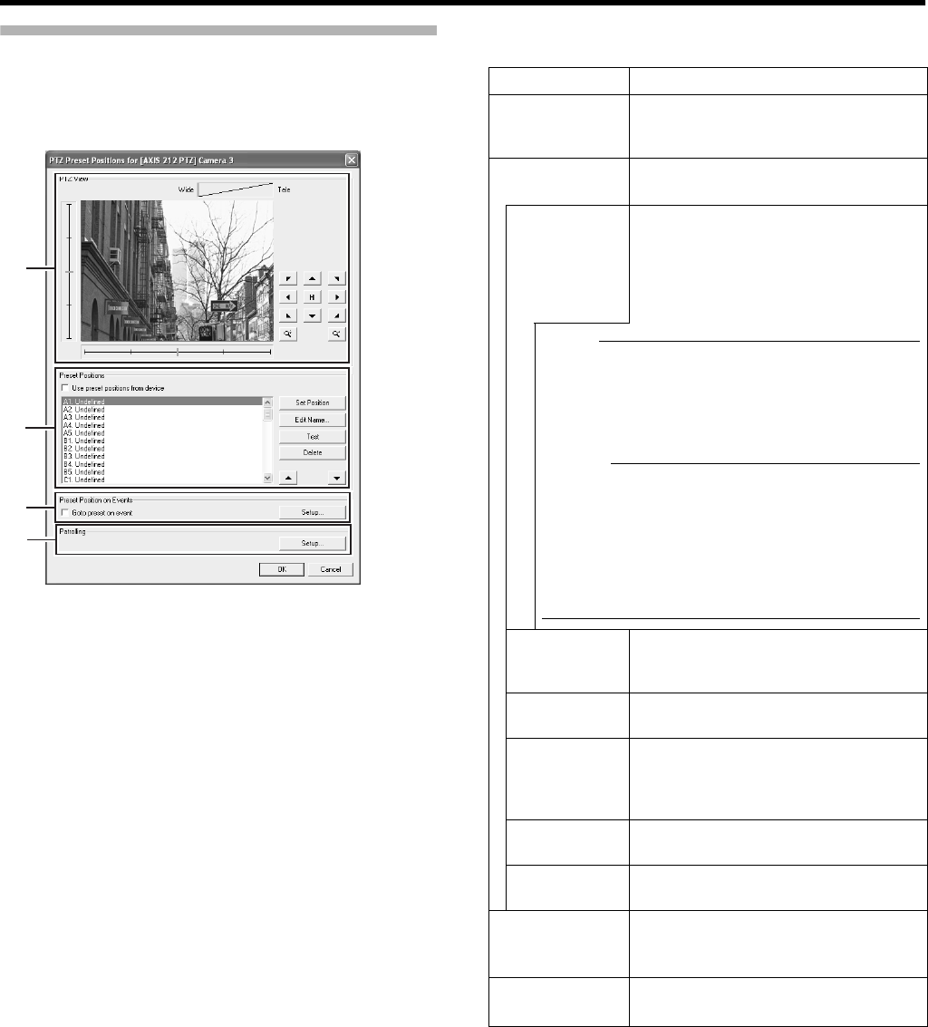
79
Display the PTZ Preset Positions window
(continued)
3 Click the [PTZ Preset Positions...] button
●The PTZ Preset Positions screen appears.
●The following configuration options are available on the
PTZ Preset Positions screen.
A
C
B
D
PTZ Preset Positions Screen
Item Description
APTZ View For moving the PTZ camera to the
desired position. You can check the
position on the screen.
BPreset
Positions
For registering, deleting and testing a
PTZ camera position.
Use preset
positions
from device
This is only applicable to cameras that
support this feature.
Select this check box to use preset
positions defined by the camera or
network encoder (IP video server).
Note :
●To import preset PTZ positions from a device, the
preset PTZ positions of this unit first has to be
deleted. Note that by doing this you will lose all
information on the preset PTZ positions in this
unit.
Memo :
●In order to use preset positions from the camera
or network encoder (IP video server) on VR-
N1600U/E, the names of the preset positions
must contain only alphanumeric characters
(space is not allowed). Preset positions with
names that contain blank characters cannot be
imported.
Set Position Registers the position specified in [PTZ
View] as the preset position selected in
the list.
Edit Name... For editing the preset position name
selected in the list.
Test For testing a defined preset position.
Select the preset position from the list,
and click the [Test] button. The result is
displayed immediately in [PTZ View].
Delete For deleting the preset position
selected in the list.
J/KFor moving a preset position selected
in the list upward or downward.
CPreset
Position on
Events
For specifying settings to move the PTZ
camera to a preset position when an
event occurs.
DPatrolling For configuring PTZ patrolling.
(APage 81 [Auto PTZ Patrolling])
VR-N1600_J.book Page 79 Wednesday, August 8, 2007 3:32 PM
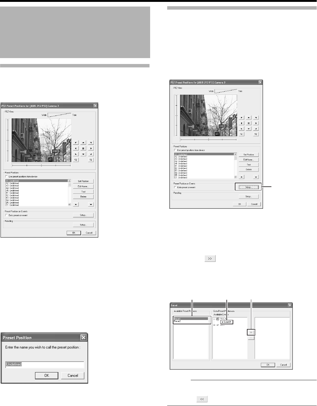
80
Applications
Defining a Preset Position
1 Display the PTZ Preset Positions window
(A Page 78)
2 Move the camera and determine the position
using the [PTZ View]
3 Select an item in the [Preset Positions] list to
register the preset position to.
●The position at the top of the list corresponds to Preset
Position 1.
●You can register up to 50 preset positions.
4 Click the [Set Position] button and name the
preset position
5 To define another preset position, repeat Steps
2 to 4.
Moving to Preset Positions by Events
This feature enables the PTZ camera to move automatically
to a preset position when an event occurs.
1 Display the PTZ Preset Positions window
(A Page 78)
2 Click the [Setup...] button of [Preset Position on
Events]
3 Select a preset position from the [Available
Preset Positions] list
4 Select an event from [Available Events]
5 Click the [ ] button
●Doing so copies the selected event to the list on the
right. This list shows events that are assigned by the
selected preset position.
Memo :
●To remove the association between a preset position and
an event, select the event from the list on the right and
click the button.
Defining a Preset PTZ
Position (continued)
PTZ Preset Positions Screen
2
PTZ Preset Positions Screen
3 4 5
VR-N1600_J.book Page 80 Wednesday, August 8, 2007 3:32 PM
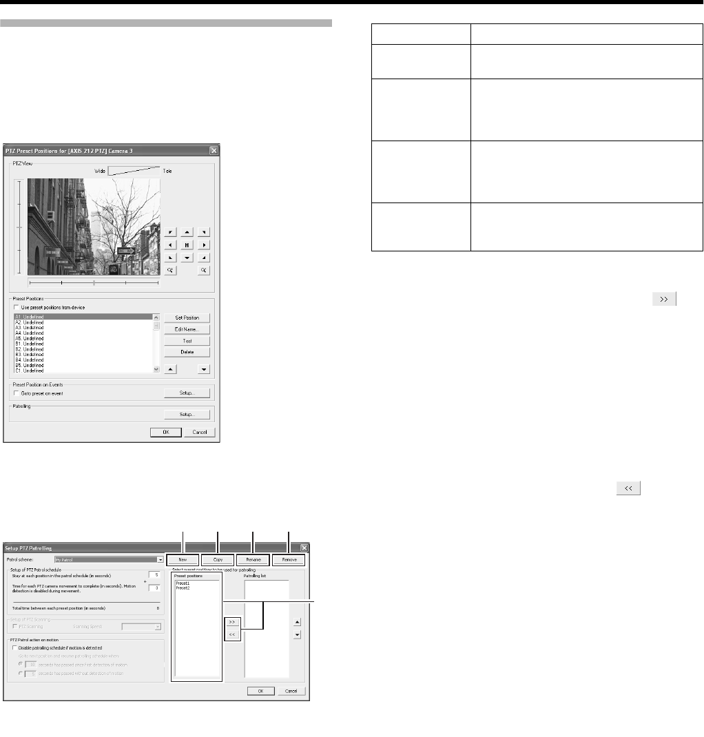
81
Auto PTZ Patrolling
PTZ patrolling is a feature that enables automatic movement
of a PTZ camera between several preset positions.
1 Display the PTZ Preset Positions window
(A Page 78)
2 Click the [Setup...] button of [Patrolling]
●The [Setup PTZ Patrolling] screen appears.
3 Select the preset positions you want to use in
the [Preset Positions] list, and click the [ ]
button.
●Doing so copies the selected preset positions to the
[Patrolling list].
●A preset position can be used more than once in a
patrol scheme.
●The camera will move between the preset positions in
the sequence shown in the [Patrolling list], starting from
the top position.
●To change the sequence of preset positions in the
[Patrolling list] list, select a preset position name, and
click the Up/Down buttons.
●To remove a preset position from the [Patrolling list],
select the preset position and click the button.
PTZ Preset Positions Screen
3
A B C D
[Setup PTZ Patrolling] Screen
Item Description
ANew For adding a new patrol scheme to the
[Patrol scheme] list.
BCopy For creating a new patrol scheme based
on an existing one. Select the patrol
scheme to copy in the [Patrol scheme]
list beforehand.
CRename For changing the name of an existing
patrol scheme. Select the patrol scheme
to rename in the [Patrol scheme] list
beforehand.
DRemove For deleting an existing patrol scheme.
Select the patrol scheme to delete in the
[Patrol scheme] list beforehand.
VR-N1600_J.book Page 81 Wednesday, August 8, 2007 3:32 PM
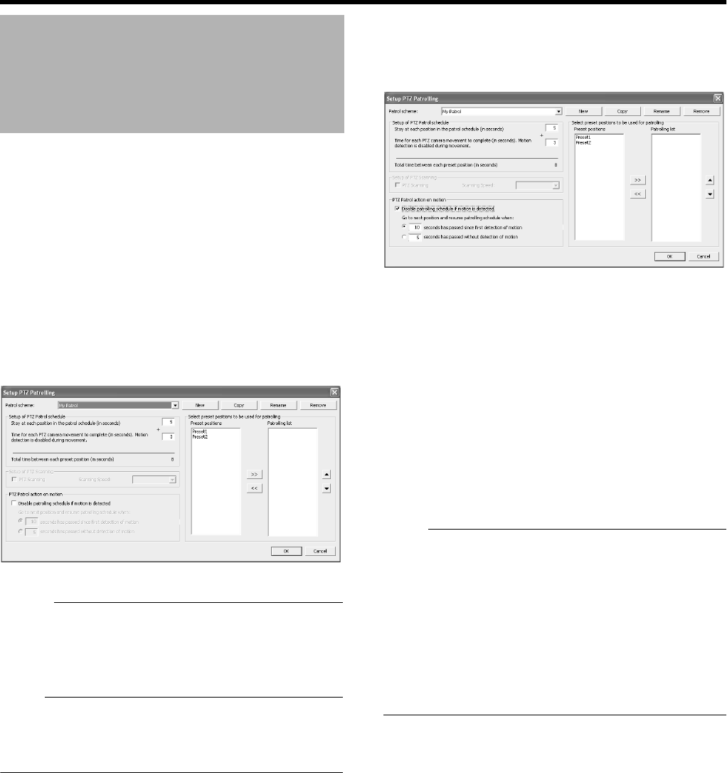
82
Applications
䡵
Specifying Patrol Timing
1 Select the patrol scheme that you want to define
from the [Patrol scheme] list
2 Specify the duration (seconds) for the PTZ
camera to stop at each preset position in the
[Stay at each position in the patrol schedule(in
seconds)] field
3 Specify the time required for the PTZ camera to
move between two preset positions in the [Time
for each PTZ camera movement to complete(in
seconds). Motion detection is disabled during
movement.] field
Memo :
●In order not to generate false motion alarms, motion
detection is automatically disabled when the PTZ camera
is moving between two preset positions. After the lapse of
the specified interval, motion detection is automatically
enabled again.
Note :
●It is important that the camera is able to reach all the
preset positions defined in the patrolling scheme within
the time interval you have specified. Otherwise, false
motion may be detected.
䡵
PTZ Patrolling Actions Upon Detection of Motion
1 Select the [Disable patrolling schedule if motion
is detected] check box
2 Select the conditions for resuming PTZ
patrolling
●When a specific time interval has lapsed after the first
detected motion, regardless of whether any
subsequent motion is detected
●When a specific time interval has lapsed after the last
detected motion
3 Specify the selected condition in units of
seconds
䡵
PTZ Scanning
For cameras that support PTZ scanning, you can enable this
feature in the [Setup of PTZ Scanning] section to select a
PTZ scanning speed.
Note :
●To define a patrol scheme, you must specify at least two
preset positions. You must also specify the period for
which the patrol scheme is enabled in [Camera Record
Setting]-[Scheduler...].
●Patrolling of PTZ cameras may be interrupted either
manually or when an event occurs. When this occurs, you
need to specify the duration (seconds) before resuming
patrolling in [Camera Record Setting]-[General
Settings]-[Patrolling Settings]. The settings in this section
are applied to all PTZ cameras installed in the system.
The default setting is 30 seconds.
Defining a Preset PTZ
Position (continued)
[Setup PTZ Patrolling] Screen
VR-N1600_J.book Page 82 Wednesday, August 8, 2007 3:32 PM
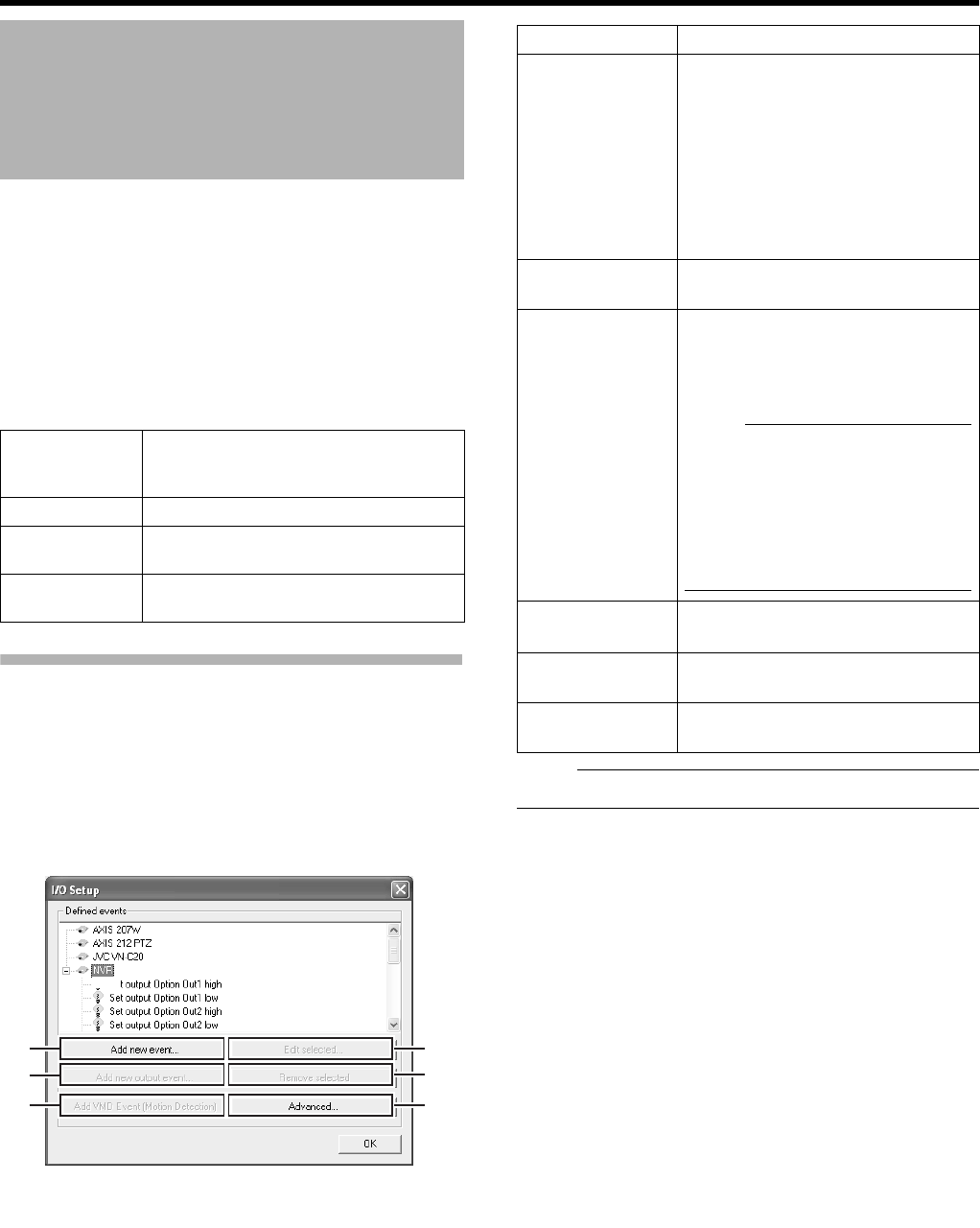
83
The input/output port is the input/output terminal that is found
on each device registered with VR-N1600U/E. You can
register the input port as [Input events], and the output port
as [Outputs...].
A registered input/output port can be linked to an event as
described below. (APage 90 [Specifying an Output Port])
●Events can be used to start recording, send e-mails, move
the PTZ camera to a preset position, and control the
output port of the device. Events are divided into the four
types as described below.
I/O Settings
1 Click the [I/O Setup...] button on the [Camera
Record Setting] screen
●The [I/O Setup] screen appears.
●The [I/O Setup] screen enables you to add input
events, VMD events and outputs that can be used by
the network cameras.
Note :
●The available events differ among network cameras.
Camera Input/Output Port
and Events
Input events Registers input signals of sensors
connected to the input port of the device
as an [Input events].
Generic events Registers as a generic event.
VMD events Registers the detected image motion as
a VMD (Video Motion Detection) event.
Event buttons Event generated by buttons that enable
manual operation.
A
B
C
F
E
D
[I/O Setup] Screen
Item Description
AAdd new
event...
For specifying input events for the
device selected in the [Defined
events] list. You may be able to
specify multiple input events for some
devices.
Click the [ +] mark next to the device
in the [Defined events] list, select the
preset input event, and click the [Add
new event...] button to specify a timer
event. (A Page 85)
BAdd new
output event...
Displays the [Add new output] screen.
(A Page 86)
CAdd VMD
Event(motion
Detection)
For specifying a VMD (Video Motion
Detection) event for the device
selected in the [Defined events] list.
Only one VMD event can be defined
for each camera.
Note :
●To avoid the risk of generating an
excessive number of VMD events,
a new VMD event cannot occur
within five seconds after the
occurrence of the last VMD event.
●VMD events cannot be sent by e-
mail.
DAdvanced... Displays the [Advanced...] screen.
(A Page 86)
ERemove
selected
For deleting the event selected in the
[Defined events] list.
FEdit
selected...
For editing the event selected in the
[Defined events] list.
VR-N1600_J.book Page 83 Wednesday, August 8, 2007 3:32 PM
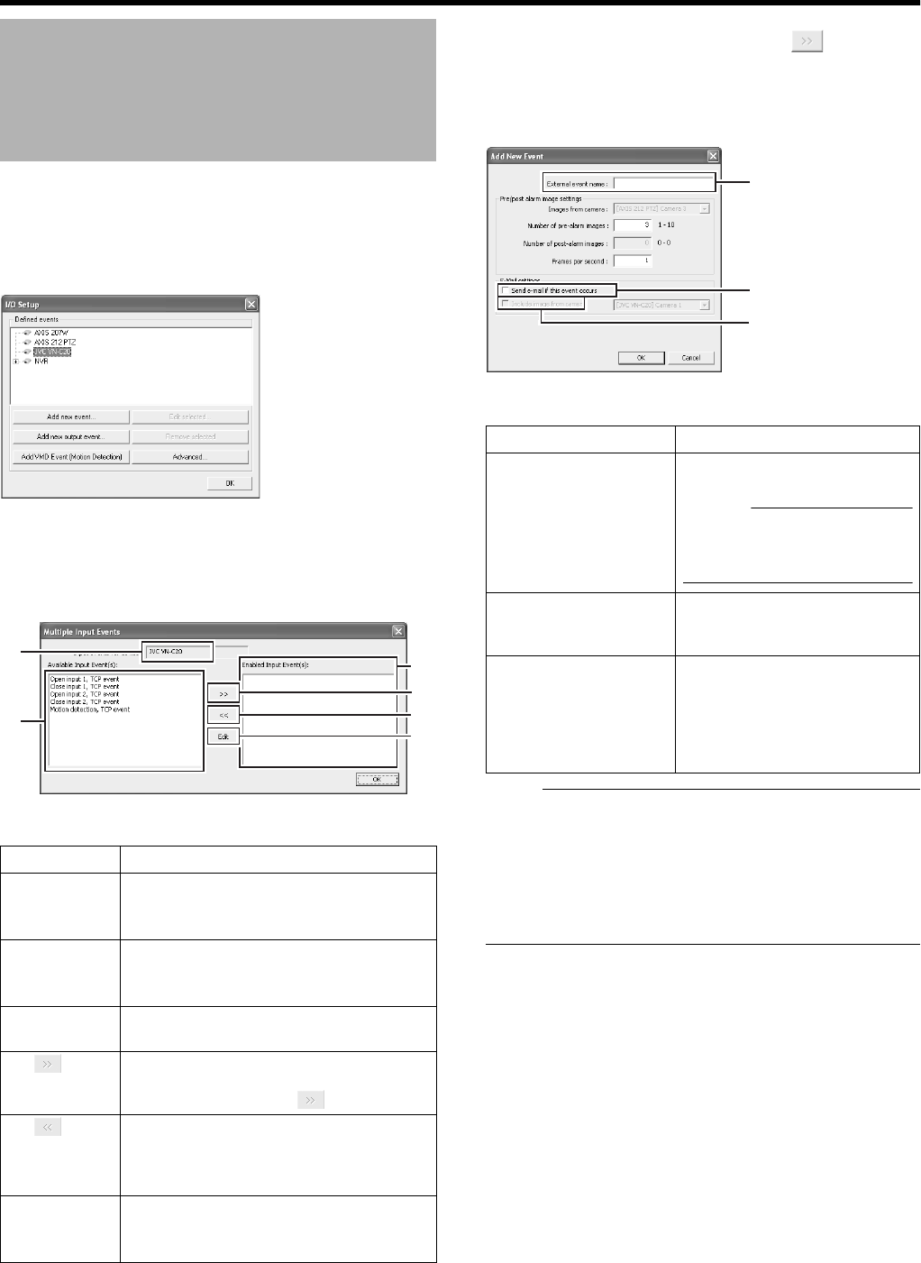
84
Applications
䡵
Specifying an Input Event
1 Select the camera for specifying the event from
the [Defined events] list on the [I/O Setup]
screen
2 Click the [Add new event...] button
●The [Multiple Input Events] screen appears.
3 Select the required event from the [Available
Input Event(S)] list and click the [ ] button to
add the event
Specify the event name and e-mail settings on the [Add New
Event] screen.
Note :
●The [Add new event...] button is disabled if there is no
event available for the network camera.
●The [Add New Event] screen may vary according to the
type of event to be added.
●If the [SKIP] and [J/K/H/I] buttons are disabled while
you are modifying the settings, use the software keyboard
(A Page 20) or the mouse.
Camera Input/Output Port
and Events (continued)
Item Description
AInput
events for
device
Displays the device name for which the
input event is specified. (This is a read-
only field.)
BAvailable
Input
Event(S)
Lists the available input events.
CEdit For editing the event setting selected in
the [Enabled Input Event(S)] list.
DYou can enable an event by selecting it in
the [Available Input Event(S)] list B,
followed by clicking the button.
EFor selecting an event in the [Enabled
Input Event(S)] list F, and moving it to the
[Available Input Event(S)] list B. Doing so
disables the event.
FEnabled
Input
Event(S)
Lists the input events that can be used.
[I/O Setup] Screen
A
B
E
D
C
F
[Multiple Input Events] Screen
Item Description
AExternal event
name
For specifying a name for the
particular input event.
Memo :
●
Event names must not contain
the following characters: < > & ' "
\ / : * ? | [ ].
BSend e-mail if this
event occurs
Select this check box to send an
e-mail alert when the input
event occurs.
CInclude image from
camera
Select this check box to attach
the currently recorded images
to the e-mail when the input
event is triggered. Select a
camera from the list next to the
check box.
A
B
C
[Add New Event] Screen
VR-N1600_J.book Page 84 Wednesday, August 8, 2007 3:32 PM
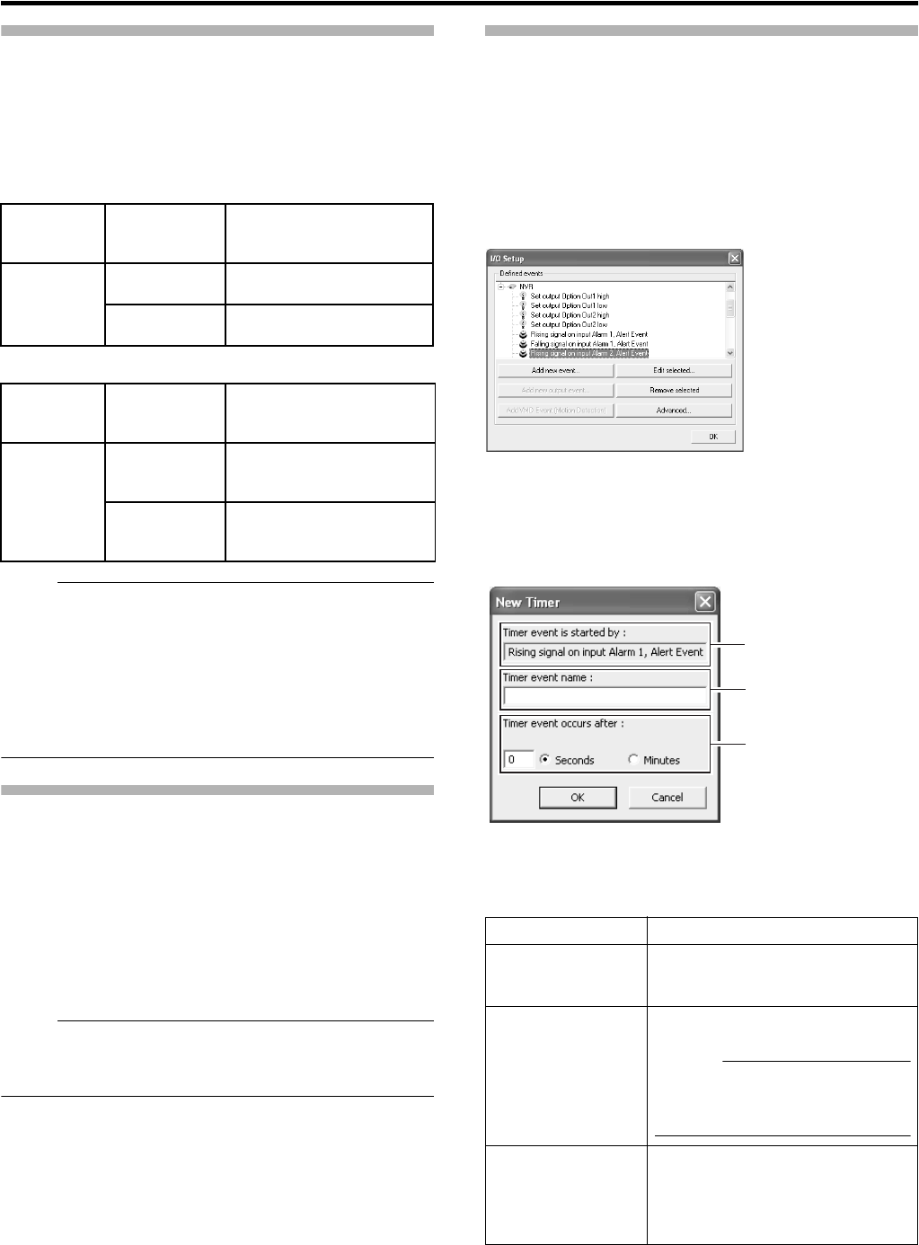
85
Input/Output Terminal on Rear Panel
●The VR-N1600U/E unit acts as a network encoder (IP
video server) in the system and the device name assigned
to it is ANVRB.
●The input/output terminals on the rear panel have been
assigned to the ANVRB device by default.
䡵
Input Terminals
䡵
Output Terminals
Note :
●The output duration of the rear output terminals is
indicated as 0 seconds in the output information. In actual
fact, output continues indefinitely.
●Output events of the rear output terminals cannot be
deleted.
●All terminal inputs are treated as alerts, but only one
terminal can be associated (Sequence) with recording
start.
Specifying a VMD Event
1 Select the camera for specifying the VMD event
from the [Defined events] list on the [I/O Setup]
screen
2 Click the [Add VMD Event(motion Detection)]
button
If a multi-camera device is selected, such as a network
encoder (IP video server), a dialog for you to select the
required camera will appear.
Note :
●The [Add VMD Event(motion Detection)] button is
disabled if there is no VMD event available for the network
camera.
Specifying Timer Events
Timer event can be attached to a special event.
Timer event will be triggled according to the specified
duration after the occurance of the related event.
1 Select the event for adding a timer event from
the [Defined events] list on the [I/O Setup]
screen(An example of when attaching to input
event)
2 Click the [Add new event...] button
●The [New Timer] screen appears.
3 Specify the timer interval and timer event name.
Input
Ter min a l
Name
Name of Input
Event
Event Description
ALARM IN 1
to 8
Alarm IN 1 to 8
Rising
Event during detection of
Make signal input
Alarm IN 1 to 8
Falling
Even during detection of
Break signal input
Output
Ter min a l
Name
Name of Output
Event
Output Action
OPTION
OUT1,2
Set output
Option Out 1,2
high
Outputs the Make status
Set output
Option Out 1,2
low
Outputs the Break status
Item Description
ATimer event is
started by:
Displays the event or event button
name for which a timer event is
added. (This is a read-only field.)
BTimer event
name
For specifying a name for the timer
event.
Memo :
●
Event names must not contain the
following characters: < > & ' " \ / : * ?
| [ ].
CTimer event
occurs after:
For specifying the time interval from
the occurrence of the event or
clicking of the event button until the
timer event is triggered. Specify the
time interval in seconds or minutes.
[I/O Setup] Screen
A
B
C
[
New Timer] Screen
VR-N1600_J.book Page 85 Wednesday, August 8, 2007 3:32 PM
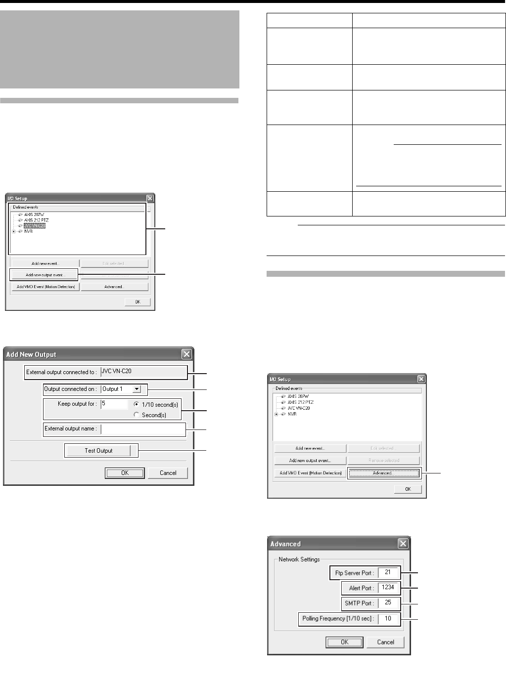
86
Applications
Specifying an Output
1 Select the camera for specifying the event from
the [Defined events] list on the [I/O Setup]
screen
2 Click the [Add new output event...] button
●The [Add New Output] screen appears.
3 Specify the output connection destination,
output holding time, and output name
Note :
●The [Add new output event...] button is disabled if there is
no output available for the network camera.
[Advanced] Screen
The [Advanced] screen enables you to specify network
settings for handling events.
1 Click the [Advanced...] button on the [I/O Setup]
screen
●The [Advanced] screen appears.
Camera Input/Output Port
and Events (continued)
2
1
A
D
B
C
E
[Add new output] Screen
Item Description
AExternal
output
connected to
Displays the device name for which
output is specified. (This is a read-
only field.)
BOutput
connected on
For selecting which destination to
connect the output to.
CKeep output
for
For specifying the output holding
time in units of 1/10 seconds or
seconds.
DExternal
output name
For specifying a name for the output.
Memo :
●Output names must not contain
the following characters : < > & ' " \
/ : * ? | [ ].
ETest Output Click this to perform a test on the
output settings.
[I/O Setup] Screen
Click
A
B
C
D
[Advanced] Screen
VR-N1600_J.book Page 86 Wednesday, August 8, 2007 3:32 PM
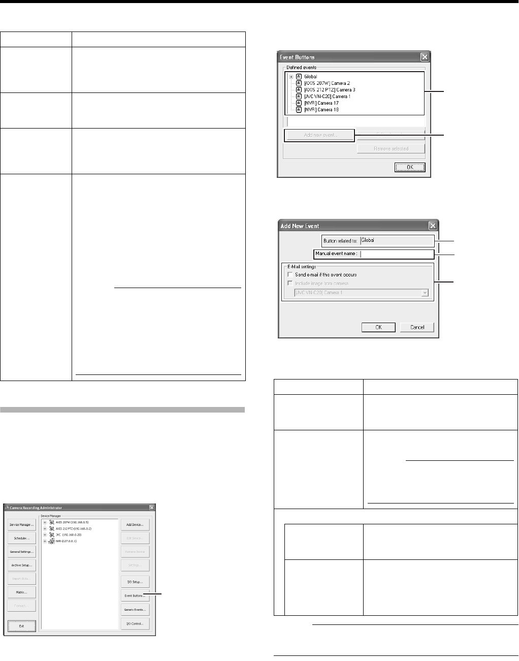
87
2 Specify the following items.
Configuring Event Buttons
Event buttons are used to manually trigger events from the
[Live Viewing] screen.
1 Click the [Event Buttons...] button on the
[Camera Recording Administator] screen
2 Select [Global] (apply to all cameras) or a
specific camera
3 Click [Add new event...] to add the event button
Memo :
●To specify a timer event for an event, select the event
added in Step 3, and click [Add new event...].
Item Description
AFtp Server
Port
For specifying the port number to use for
sending event information from the
device to the surveillance system via
FTP.
BAlert Port For specifying the port number to use for
handling warnings related to events,
including generic events.
CSMTP Port For specifying the port number to use for
sending event information from the
device to the surveillance system via
SMTP.
DPolling
Frequency
[1/10sec]
For some devices, the surveillance
system may need to check the status of
their input ports in order to detect
whether input has been received. These
regular status checks are called
ApollingB.
The [Polling Frequency[1/10sec]] field
enables you to specify the interval
between status checks. Specify the
interval in units of 1/10 seconds.
Memo :
●For I/O devices, it is highly
recommended that the polling
frequency be shortened as much as
possible.
●Refer to the “Instruction Manual” of
the I/O device for devices that require
polling.
[Camera Recording Administator] Screen
[Event Buttons]
Item Description
AButton related
to
Displays the camera name for which
the event is specified. (This is a
read-only field.)
BManual event
name
For specifying a name for the event
button.
Memo :
●
Event names must not contain the
following characters: < > & ' " \ / : * ? |
[ ].
CE-Mail settings
Send e-mail if
this event
occurs
Select this check box to send an e-
mail alert when the event button is
clicked.
Include image
from camera
Select this check box to attach the
currently recorded images to the e-
mail when the event button is
clicked. Select a camera from the
list below the check box.
3
2
A
B
C
[Add New Event] Screen
VR-N1600_J.book Page 87 Wednesday, August 8, 2007 3:32 PM
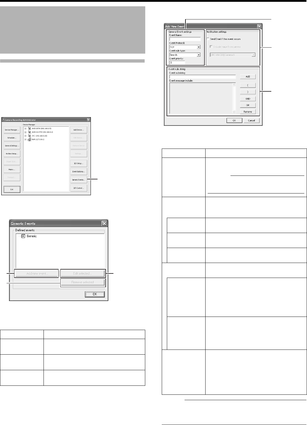
88
Applications
Specifying Generic Events
This section describes procedures for specifying an event for
the TCP/UDP protocols. The event will be triggered if the
received data meets the specified criteria.
1 Click the [Generic Events...] button on the
[Camera Recording Administator] screen
2 Select Generic and click [Add new event...]
AGeneral Event settings
Memo :
●VR-N1600U/E receives generic events from the port that
is specified in [Alert Port] on the [Advanced] screen.
(A Page 86)
Camera Input/Output Port
and Events (continued)
Item Description
AAdd new
event...
For adding new events.
BRemove
selected
For deleting the event selected in the
[Defined events] list.
CEdit
selected...
For editing the event selected in the
[Defined events] list.
[Camera Recording Administator] Screen
[Generic
Events...] Button
A
B
C
[Generic Events] Screen
Item Description
Event Name
For specifying a name for the event. Enter a
unique name for the event.
Memo :
●
Event names must not contain the
following characters: < > & ' " \ / : * ? | [ ].
Event Protocol
For selecting the protocol that VR-N1600U/E
uses to receive data when detecting the
event:
Any
Receives and analyzes data that uses either
the TCP or UDP protocol.
TCP
Receives and analyzes only data that uses
the TCP protocol.
UDP
Receives and analyzes only data that uses
the UDP protocol.
Event rule type
For specifying the rules when analyzing the
received data.
Match
In order for an event to be triggered, the
received data must totally coincide with the
message specified in the [Event message
include] field of the [Event rules string]
section
C
, and must not contain any other
messages.
Search
n order for an event to be triggered, the
received data must contain the message
specified in the [Event message include] field
of the [Event rules string] section
C
. Other
messages may be included in the data.
Event priority
The same data may be used by different
events. Assigns the order of priority to each
event for determining the event to trigger
when the received data matches the criteria
of multiple events. Set the priority level to a
value between
A
0
B
(lowest priority) and
A
1000
B
(highest priority).
B
C
A
[Add New Event] Screen
VR-N1600_J.book Page 88 Wednesday, August 8, 2007 3:32 PM

89
BNotification settings
CEvent rules string
Memo :
●To specify the timer settings for a generic event, select the
event added in Step 2, and click the [Add new event...]
button.
Item Description
Send e-mail if
this event
occurs
Select this check box to send an e-mail
alert when an event occurs.
Include image
from camera
Select this check box to attach the
currently recorded images to the e-mail
when the input event is triggered. Select
a camera from the list below the check
box.
Item Description
Event
substring
For specifying the expression to search
for during analysis of data by VR-
N1600U/E.
Specify at least one expression, and
click the [Add] button. The specified
expression is added to the [Event
message include] field.
If you have added multiple expressions
as one item, the expressions enclosed in
the quotation marks must appear
together in the data in the specified
sequence in order to match the criteria.
Event
message
include
Displays the string that is used for the
actual data analysis. The field is not
directly editable. However, you can place
the cursor inside the field and click the
following buttons.
Add Adds the information in the [Event
substring] to the [Event message
include] field.
(Adds [(] to the [Event message include]
field.
The parenthesis is used to process the
expressions as a single entity. In other
words, the content inside the
parenthesis is processed first.
)Adds [)] to the [Event message include]
field.
AND Adds the operator AANDB to the [Event
message include] field. Use the AANDB
operator when you want to specify that
the expressions on both sides of AANDB
must be included.
OR Adds the operator AORB to the [Event
message include] field. Use the OR
operator when you want to specify that
either one of the expressions on the two
sides of OR must be included.
Delete For deleting the item to the left of the
cursor in the [Event message include]
field.
VR-N1600_J.book Page 89 Wednesday, August 8, 2007 3:32 PM
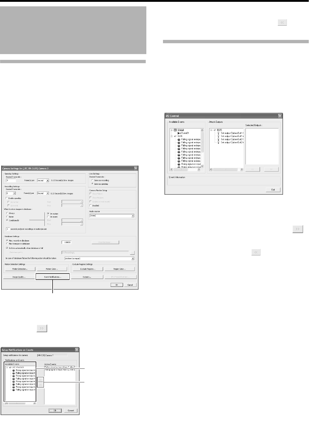
90
Applications
Event Notification Settings
You can select events for triggering event notifications, and
display them in yellow, red or green on the [Live Viewing]
screen. The yellow indicator lights up when the specified
event has occurred, the red indicator lights up when motion
has been detected, and the green indicator lights up when
images are received from a camera.
1 Select the camera to configure from the [Camera
Recording Administator] screen, and select
[Settings...]
●A setting dialog box appears.
2 Click the [Event Notifications...] button
3 Select the event to trigger notification from
[Available Events]
4 [Click the button
●The selected event is copied to [Active Events].
5 Repeat 2to4 for each event
●To delete an event for which notification has been
configured, select the event and click the [ ] button.
Specifying an Output Port
A specific event or [Manual event name] button can be
associated with a particular output port.
To do this, specify the output port from which output is to be
triggered when a specific event or manual event occurs.
1 Select [I/O Control] from the [Camera Record
Setting] screen
●A setting dialog box appears.
2 Select the event to specify from the list on the
left
3 Select the output to specify, and click the [ ]
button located below [Selected Outputs]
●To delete an output from the [Selected Outputs] list,
select the output and click the [ ] button.
Camera Input/Output Port
and Events (continued)
2
[Camera Settings]
Screen
3
4
[Setup Notifications on Events] Screen
[I/O Control] Screen
VR-N1600_J.book Page 90 Wednesday, August 8, 2007 3:32 PM
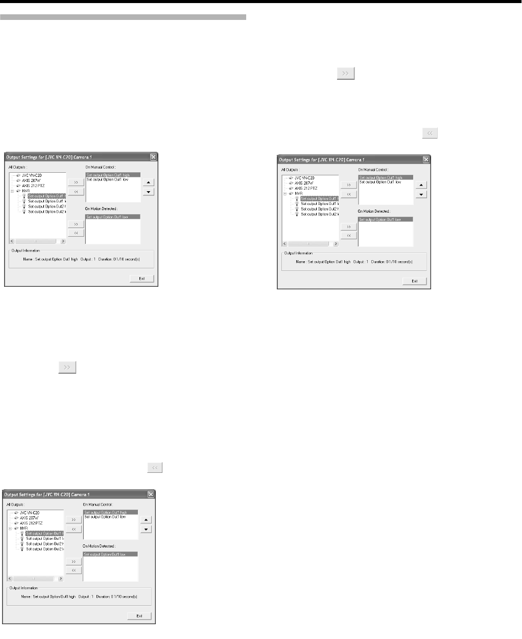
91
Camera Output Settings
You can assign external outputs specified on the [I/O Setup]
screen to a camera, such as the sounding of a siren or
switching on of lights.
●The assigned outputs can be triggered automatically
when motion is detected, or manually by pressing the
output buttons.
●You can display the [Output Settings] screen by clicking
the [Outputs...] button on the [Camera Recording
Administator] screen (A Page 49).
䡵
Specifying Output During Manual Control
You can specify outputs to be triggered manually using the
output button or from a list on the [Live] screen.
1 Select an output from the [All Output] list
2 Click the button between the [All Output]
and [On Manusl Control] lists
●Doing so copies the selected output to the [On Manusl
Control] list.
●You can use the Up/Down buttons at the top right
corner of the [On Manusl Control] list to move the
selected output upward/downward within the [On
Manusl Control] list.
●To delete an output from the [On Manusl Control] list,
select the output and click the button between the
[All Output] and [On Manusl Control] lists.
䡵
Specifying Output via Motion Detection
You can specify outputs to be triggered automatically when
motion is detected.
1 Select an output from the [All Output] list
2 Click the [ ] button between the [All Output]
and [On Motion Detected] lists
●Doing so copies the selected output to the [On Motion
Detected] list.
●To delete an output from the [On Motion Detected] list,
select the output and click the [ ] button between the
[All Output] and [On Motion Detected] lists.
[Output Settings] Screen
[Output Settings] Screen
[Output Settings] Screen
VR-N1600_J.book Page 91 Wednesday, August 8, 2007 3:32 PM
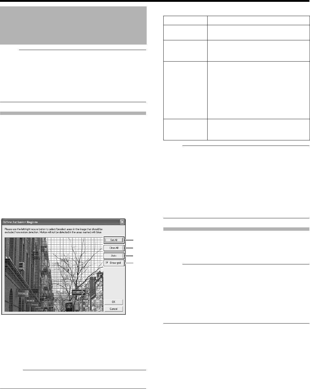
92
Applications
Note :
●Before configuring the motion detection settings, it is
recommended that you complete the settings related to
image resolution, compression, and motion detection
exclusion areas. Otherwise, you may need to adjust the
sensitivity level in the motion detection settings again
when you change the picture quality and set the exclusion
areas at a later date.
Defining Motion Detection Exclusion Regions
You can specify specific areas to be excluded from motion
detection to prevent the detection of irrelevant motion, such
as swaying trees in the wind or cars that drive past
continuously in the background.
1 Select a camera from the [Device Manager] on
the [Camera Recording Administator] screen,
and click [Exclude Regions...] in [Settings...]
●If the [Show Grid] check box is selected, the preview
screen appears, which is divided into small areas by a
grid. Areas highlighted in blue indicate the exclusion
areas.
2 To select an area, click and drag the mouse
pointer to move the grid on the screen
●Selected areas are highlighted in blue.
Memo :
●To clear the exclusion areas, right click and drag the
mouse pointer to move the grid.
䡵
Setting Buttons and Check Boxes
Note :
●Note that when motion detection is set at short intervals,
the number of alarms may increase and a longer search
time may be required during playback.
●When a camera is connected, flickers such as those of a
fluorescent light may cause a false motion detection. In
this case, set the camera to flickerless.
●Noises in the camera image may also trigger a false
detection. Set the camera to prevent false detection even
when the ACG function is enabled, such as during
nighttime.
Specifying Motion Detection.
Motion detection enables you to specify the timing to
transfer images from the camera, generate alerts, and trigger
external outputs (lights or sirens).
Note :
●This feature is essential to the system’s operation. In
order to avoid unnecessary alerts during application, it is
recommended that you specify the settings for each
camera carefully. Depending on the physical location
where the camera is installed, it may be necessary to
perform tests and adjustments of the settings under
different conditions (time of the day, weather such as
windiness, etc.).
1 Select a camera from [Device Manager] on the
[Camera Recording Administator] screen, and
click the [Motion Detection..] button in
[Settings...] to open [Adjust Motion Detection]
2 Specify [Noise Sensitivity] and [Motion
Sensitivity]
●The [Noise Sensitivity] slider is used to determine the
level of change in the image pixel that is to be
recognized as motion. The AHighB setting recognizes
minute changes in the pixel as motion. Areas in the
image that have changed when compared with the
previous image are highlighted (default color is green).
Motion Settings
A
B
C
D
[Exclude Regions...] Screen
Item Description
ASet All Sets all sections in the grid on the
preview image as exclusion areas.
BClear All Clears all sections in the grid on the
preview image that are specified as
exclusion areas.
CAuto Click this button to automatically detect
areas with insignificant image changes
(noises) that are not to be detected as
AmotionB, and mark such areas to
exclude them from motion detection. As
a large number of images need to be
analyzed during the marking operation,
it may take a while to complete after you
have clicked the [Auto] button.
DShow Grid Select this check box to enable the
display of grids on the preview image.
The default setting is [Show Grid].
VR-N1600_J.book Page 92 Wednesday, August 8, 2007 3:32 PM
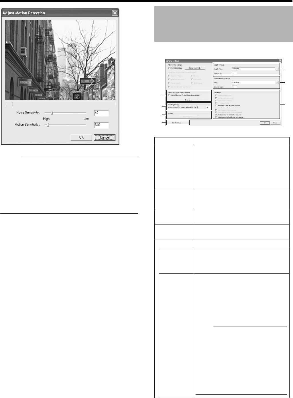
93
Memo :
●The [Motion Sensitivity] slider is used to determine the
number of pixels for which a change is to be recognized
as motion. When the slider is moved from side to side, the
black vertical line at the bottom of the screen moves
together, and the boundary (Motion Sensitivity) is
adjusted. When detected motion is above the selected
sensitivity level, the bar changes color from green to red,
indicating a positive detection.
Use [Camera Record Setting]^[General Settings] to specify
general settings related to the system, such as e-mails.
[Adjust Motion Detection] Screen
General Settings
Item Description
AMilestone
XProtect
Central
Settings
Settings for using Milestone XProtect
Central by Milestone Systems.
For details, refer to the XProtect Central
User’s Manual provided by Milestone
Systems.
(http://www.milestonesys.com/
?cid=265)
BPatrolling
Settings
Specify the settings in this section when
you are using PTZ cameras for the
patrolling feature. (A Page 81)
CJoystick For specifying settings related to the
joystick. (A Page 119)
DE-Mail
settings
For specifying the e-mail settings.
(A Page 94)
EAdvanced
Don't send
e-mail on
camera
failures
Select this check box to stop sending e-
mail alerts if a camera is no longer in the
online mode.
Start
cameras on
remote live
requests
You are able to view live images from
cameras even when they are in the
offline mode.
When the live image screen of the NVR
Viewer appears, the camera
automatically switches to the online
mode and records the image according
to the recording settings.
Note :
●:When AStart cameras on remote live
requestsB is selected, the camera
switches to the online mode while
you are viewing live images.
Depending on the settings when in
the recording control mode, recording
may start when you start viewing live
images. This also applies to viewing
live images on a surveillance
computer.
A
G
F
E
B
C
D
[General Settings] Screen
VR-N1600_J.book Page 93 Wednesday, August 8, 2007 3:32 PM
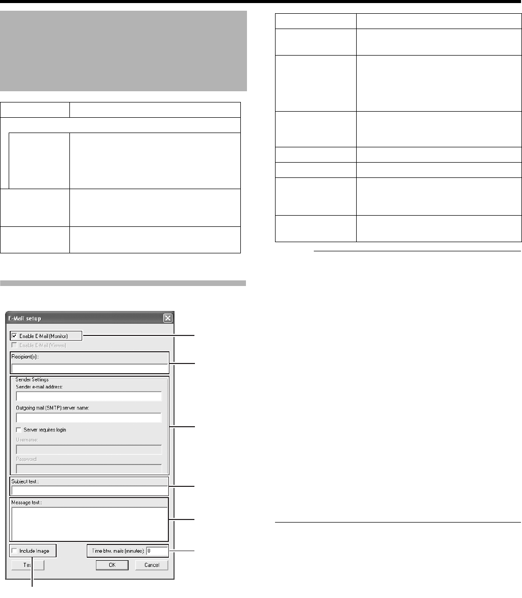
94
Applications
E mail Settings
Memo :
●You can send a test e-mail by clicking the [Test] button. If
the e-mail address of the sender is not registered with the
mail server of the recipient, the [The mail address of the
sender is not valid. ...] message may appear. When this
occurs, double-check the sender’s e-mail address and
outgoing mail server, and re-enter the e-mail address.
●E-mail messages are sent in the following cases.
●When an input event occurs
(APage 84 [Specifying an Input Event])
●When the event button is clicked
(APage 87 [Configuring Event Buttons])
●When a generic event occurs
(APage 88 [Specifying Generic Events])
●When motion is detected
(APage 92 [Specifying Motion Detection.])
●When camera failure occurs
●When an archiving error occurs
(APage 95 [Archiving])
●In order to send an e-mail, you need to specify the timing
for sending out e-mails in [Scheduler Setting] (A Page
47).
●After you have completed the e-mail setting, perform a
test to verify that it can be sent successfully.
General Settings
(continued)
Item Description
EAdvanced (continued)
Create
default
schedule
for new
cameras
Select this check box to automatically
create the online schedule of the
camera in the [Scheduler] at all times.
(A Page 47)
FEvent
Recording
Settings
Do not change.
GLogfile
Settings
Do not change.
A
B
C
D
E
G
F
[E-mal setup] Screen
Item Description
AEnable E-
mail(Monitor)
Select this check box to enable
sending of e-mail alerts.
BRecipient(S) For specifying the e-mail addresses to
send alerts to. If you are specifying
more than one e-mail address,
separate the e-mail addresses using
semicolons.
CSender
Settings
For specifying the sender’s e-mail
address, outgoing (SMTP) mail server
name and login settings.
DSubject text For specifying the mail title.
EMessage text For specifying the message text.
FTime
btw.mail(min
utes)
For specifying the time interval
(minutes) for sending each e-mail
alert.
GInclude
Image
Select this check box to include
images in the message.
VR-N1600_J.book Page 94 Wednesday, August 8, 2007 3:32 PM
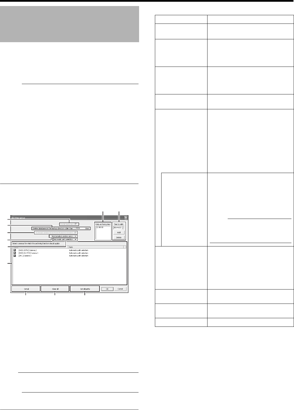
95
With the archiving feature, you can store recorded images up
to the maximum available capacity of the hard disk.
By default, recorded images received from cameras are
stored in the database for each camera, and data is archived
automatically once the database is full.
Memo :
●To adjust the database settings for each camera, click
[Camera Record Setting]-[Device Manager]-[Camera
Name]- and select [Datebase Settings]. You can store up
to 600,000 frames or 40 GB of data. If the maximum
capacity is exceeded, data is deleted starting from the
oldest information. By archiving on a daily basis, you can
store image data up to the maximum available capacity of
the hard disk.
●You can specify the number of times to create archives in
a day.
●The archiving location for each camera is automatically
selected. The drive with a large amount of free space is
selected.
●You can use the playback features for archived images in
the same way as normal recorded images.
1 Click [Camera Recording Administator]-
[Archive Setup]
2 Specify the number of days for storing the
archived data in [Delet databases in the backup
directory older then[ ] days]
3 Use the [Add] and [Delete] buttons to specify the
time to create archives everyday.
4 Select the camera for which archive is to be
created
Note :
●The recorded images may be interrupted for several
seconds when archiving starts.
Memo :
●If audio is enabled during recording, audio data from the
device will also be archived.
䡵
Setting Items and Buttons
Archiving
A
C
B
D
E
F
G H I
JK
[Archive Setup] Screen
Item Description
AEnable
Archiving
This function is not available.
Check box is selected at all times.
BDelet databases
in the backup
directory older
then[ ] days
For specifying the number of days
you want to store archived images.
CAutomatic
delete old
archives if
space is needed
This function is not available. Check
box is selected at all times.
DSend email on
archive error
Sends out an e-mail alert when
archiving fails.
EAutomatic path
selection
The archiving location is
automatically selected. The drive
with a large amount of free space is
selected.
Select this check box.
If the check box is deselected, the
[Save to] button appears.
Deselect this check box if you are
specifying a drive to save the
archive data to, such as NAS.
Select Directory Appears when the [Automatic path
selection] check box is not selected.
Specify the archive location for
each camera. Enter the archive
location if you are specifying a drive
to save the archive data to, such as
NAS.
Note :
●Playback of the old archive data
will fail if the archive destination
is changed after saving.
FSelect cameras
for which the
archiving
function should
apply
If you have selected the [Enable
Archiving] check box, a list of
cameras that enable archiving
appears.
To specify the archiving settings for
a specific camera, select the check
box next to the name of the camera.
GSet All Selects the check box for all
cameras.
HClear All Clears the check box for all
cameras.
ISet all paths Not used.
VR-N1600_J.book Page 95 Wednesday, August 8, 2007 3:32 PM
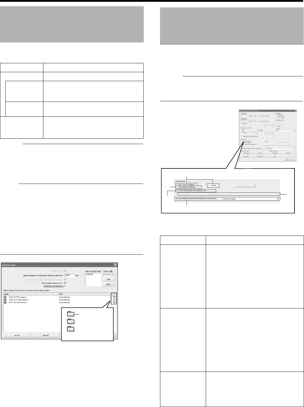
96
Applications
䡵Setting Items and Buttons
Memo :
●NAS is a file server that is connected to the network. You
can specify the NAS as a drive for archiving data using
VR-N1600U/E.
●For details on the NAS drive settings, refer to the [Details]
item in [HDD Utility] (A Page 103).
Note :
●When other operations (e.g., startup of Live Viewing)
overlap with the startup of the archiving process, up to 3
seconds of the recording may be lost.
●Do not specify the same NAS drive for multiple cameras. If
there is an insufficient number of NAS drives to be
specified for each camera, divide the NAS drive into
multiple partitions, and configure each of them as a
separate NAS drive.
●Playback of data before the change may fail if the
[Automatic path selection] settings are altered.
This section enables you to specify the database settings.
Select a camera from [Main Menu]-[Camera Record
Setting]-[Device Manager], and select -[Settings...].
Memo :
●Recorded image data is referred to as the database in this
manual.
The recorded images are saved as database.
䡵Specify the database settings
Archiving (continued)
Item Description
JTime to add For specifying the archiving time.
Add Adds the archiving time specified in the
[Time to add] field to the [Daily archiving
times] K list.
Delete Removes a selected archiving time from
the list.
KDaily
archiving
times
Lists specified archiving times. Archiving
takes place everyday at the specified
time.
Select
Directory
Button
Database Settings
Item Description
AMax.records
in database
Saves recorded images to the
database until the maximum number of
records is reached. Specify the
maximum number of records in the
neighboring field.
If the [Archive automatically when
database is full]C check box is not
selected, old records are automatically
overwritten upon exceeding the
maximum number of records.
BMaxtimespan
in database
Saves recorded images to the
database up to the specified recording
time. Specify the total recording time
from the list in the neighboring field in
minutes, hours and days.
If the [Archive automatically when
database is full]C check box is not
selected, old records are automatically
overwritten upon exceeding the
recording time.
C
Archive
automatically
when
database is
full
Starts archiving data automatically
when the database is full.
Deletes old archive data when the
available space of the hard disk is
running low.
A
B
C
D
E
[Camera Settings] Screen
VR-N1600_J.book Page 96 Wednesday, August 8, 2007 3:32 PM
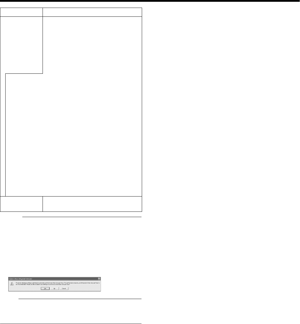
97
Memo :
●The database can store up to 600,000 records.
●The maximum database size is set to 108,000 records by
default. Do not change this setting as it may adversely
affect the recording time and recording performance.
●When archiving is used, you can store images without
being constrained by this limit.
●The following screen may appear for some settings. When
it appears, click [No].
Note :
●If you are not using a UPS, it is recommended that you
select AMaxtimespan in databaseB and set the time to
A60minutesB.
Item Description
DIn case of
database
failure the
following
action
syould be
taken
For selecting the action to take when
problems are found in the database. The
number of options available varies
depending on whether archiving is
enabled.
Select AArchive(no repair)B. If you have
selected another option, the data may
be lost if problems occur in the
database.
[Repair,Scan,Delete if fails]:
Two different repair methods, quick repair (recovery) and
complete repair (scan) are used. Content of the
database will be deleted if both repair methods fail.
[Repair,Delete if fails]:
The fast repair method is used. Content of the database
will be deleted if fast repair fails.
[Archive if fails]:
This option is available only if archiving is enabled for the
camera. The fast repair method is used. Content of the
database will be archived if fast repair fails.
[Delete(no repair)]:
Do not select this item.
[Archive(no repair)]:
This option is available only if archiving is enabled for the
camera. Content of the database is archived. Select this
option.
EDatebase
path
Do not change the settings.
VR-N1600_J.book Page 97 Wednesday, August 8, 2007 3:32 PM
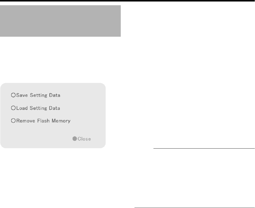
98
Applications
You can save set values to flash memory devices or retrieve
data from them.
1 Select [Flash Memory Utility] from the main
menu
●The Flash Memory Utility screen appears.
䡵
Save Setting Date
The following are procedures to save the preset data in the
flash memory device.
1 Insert the flash memory device into the
[SERIAL] terminal on the front or rear panel
2 Select [Save Setting Date]
●A [Save Setting Data?] confirmation message appears.
●The [Flash memory cannot be detected] message may
appear in some cases. In this case, wait for about 30
seconds and select [Save Setting Date] again.
3 Press the [OK] button
●The preset data is saved.
●When saving is finished, a message informing you that
the data has been saved will be displayed. Click the
[OK] button again.
4 Select [Remove Flash Memory]
●The [Remove Flash Memory?] confirmation message
appears. Press [OK].
●The [Flash Memory was removed] message appears.
Press [OK].
5 Remove the flash memory device from the
[SERIAL] on the front or rear panel
Memo :
●Items specified in the [Password] sections (A Page 62) of
the [Image Quality...] settings (A Page 52), [OS
Setting](A Page 64), and [Unit Setting] in [Main Menu]-
[Camera Record Setting] will not be saved.
●Settings data is saved to the VR-N1600U/E folder in the
flash memory (USB memory).
●To save the preset data after you have selected [Remove
Flash Memory], remove the flash memory device from the
serial terminal and insert it again. The flash memory
inserted will be automatically detected.
Flash Memory Utility
Flash Memory Utility Screen
VR-N1600_J.book Page 98 Wednesday, August 8, 2007 3:32 PM
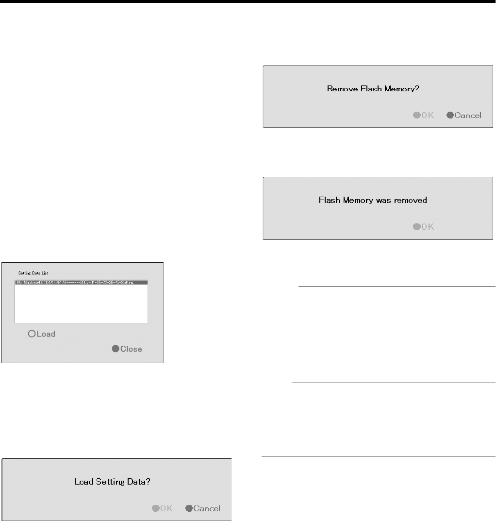
99
䡵
Reading Preset Data
This section describes procedures for reading the preset
data from the flash memory.
1 Insert the flash memory device into the
[SERIAL] terminal on the front or rear panel
2 Select [Load Setting Data]
●If data is stored on the flash memory device, a list of
data stored in the device will appear in the preset data
list.
●The [Flash memory cannot be detected] message may
appear in some cases. In this case, wait for about 30
seconds and select [Load Setting Data] again.
●Preset data that is stored on this unit is indicated by
AMy MachineB at the beginning. Data stored on other
VR-N1600U/E units is displayed as AOther MachineB.
This is followed by a pair of parentheses, which
contains the MAC address of the VR-N1600U/E at the
time when data was saved. This is followed by the
saved date/time in the Ayyyy-mm-dd-sec-SettingB
format.
●If multiple data are displayed, highlight the data in the
list that you want to read.
3 Select the setting data to read, and press [Load]
●The highlighted data will be read.
4 The [Load Setting Data?] confirmation
message appears. Press [OK].
●The preset data will be read.
●When reading is finished, a message informing you
that the data has been read will be displayed. Click the
[OK] button again.
5 Press [Close] to return to the [Flash Memory
Utility] screen
䡵
Removing the Flash Memory Device
1 Select [Remove Flash Memory]
●The [Remove Flash Memory?] confirmation dialog
appears. Press [OK].
●The [Flash Memory was removed] message appears.
Press [OK].
2 Remove the flash memory device from the
[SERIAL] on the front or rear panel
Memo :
●Items specified in the [Password] sections (A Page 62) of
the [Image Quality...] settings (A Page 52), [OS
Setting](A Page 64), and [Unit Setting] in [Main Menu]-
[Camera Record Setting] will not be read.
●To read the preset data after you have selected [Remove
Flash Memory], remove the flash memory device from the
serial terminal and insert it again. When the flash memory
is inserted, it will be automatically detected.
Note :
●If you are reading preset data saved using a different
language setting, change [Language Setting] of the [Main
Menu] to the language used when the data is saved.
●If a Master/Slave setup is created using Milestone
System’s Enterprise 6.0 on an VR-N1600U/E, settings on
that unit cannot be loaded on another VR-N1600U/E.
[Setting Data List] Screen
VR-N1600_J.book Page 99 Wednesday, August 8, 2007 3:32 PM
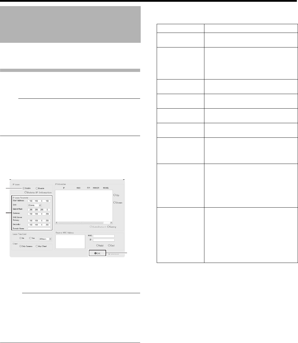
100
Applications
This section enables you to assign an IP address to each
camera and configure various auto detect settings.
Specifying IP Lease
For configuring the function to assign IP addresses to each
network camera.
Note :
●In order to assign an IP address of the network camera
using the IP Lease feature, you need to enable the DHCP
of the network camera. For procedures to enable the
DHCP of the network camera, refer to the instruction
manual of the network camera.
1 Select [Auto Detect Setting] from [Main Menu]
●The [Auto Detect Settings] screen appears.
2 Select [Enable] in [IP Lease]
Memo :
●If a network uses a multiple number of VR-N1600U/E
units, enable the [IP Lease] only for one unit. Select
[Disable] if a DHCP server is operating on the same
network.
●When the [IP Lease] is enabled for two or more devices at
the same time, the IP address may change to a static
address, and cause malfunction of the cameras.
3 Specify the following items under [IP Lease
Parameter]
4 Click [OK]
●Doing so closes the setting screen and starts the IP
Lease feature.
●Select ADisableB in Step 2 to stop the IP Lease
feature.
Auto Detect Settings
2
3
4
[Auto Detect Settings] Screen
Item Description
Start Address For specifying the first IP address to
be assigned to the cameras.
Unit For selecting the number of IP
addresses to be assigned to the
cameras. The selected number of IP
addresses will be assigned starting
from the first IP address.
Subnet Mask For specifying the subnet mask for the
cameras.
Default Gateway For specifying the gateway for the
cameras.
DNS Server For specifying the DNS server address
for the camera(s).
Domain Name For specifying the domain name for
the cameras.
Lease Time Limit For specifying the valid period of the
IP address assigned to the cameras. If
AYe s B is selected, you can set the
lease time in units of hours.
Client For selecting whether to apply
restrictions on the device when
assigning the IP address. If AOnly
CameraB is selected, IP address will
only be assigned to the corresponding
camera. If AAny ClientB is selected, IP
address will be assigned to all devices.
Reserve MAC
Address
Configure the [Reserve MAC Address]
if you want to assign a specific IP
address to the cameras. A specific IP
address is always mapped to a MAC
address. Enter a value in the MAC and
IP fields, and click [Add] to set the
addresses. To cancel the setting,
select a displayed MAC and IP
address and click [Del].
VR-N1600_J.book Page 100 Wednesday, August 8, 2007 3:32 PM
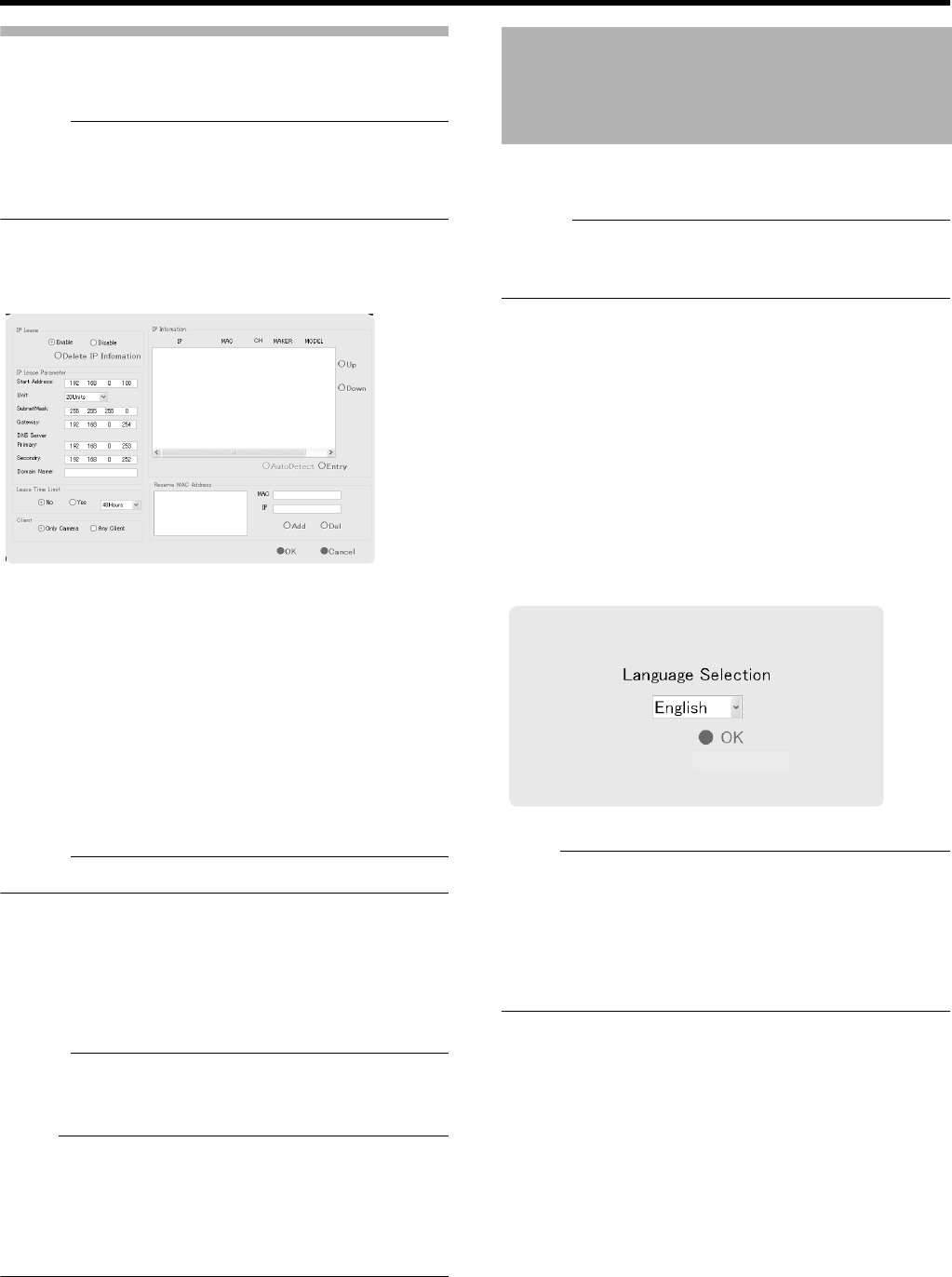
101
Using the Auto Detect Feature
The Auto Detect feature enables automatic detection of
network cameras.
Memo :
●When multicast packets are configured such that they do
not pass through the network equipment, such as a
switching hub, the Auto Detect of the camera may not
function properly.
The [IP Information] list contains information on the IP
address of the automatically detected camera, MAC
address, number of video CH, manufacturer, and model.
1 Click [Auto Detect]
●Auto Detect starts and the camera image appears on
the screen.
2 Changing the Order of Detected Cameras
●You can sort the order of the detected cameras by
clicking the Sort button.
●The different types of sort buttons include the [IP],
[MAC], [CH], [MAKER], and [MODEL] sort buttons.
●After selecting the detected camera, click the [Up] or
[Down] button to alter the order of the cameras.
●Deselect the check box of any camera that you are not
using.
Memo :
●The camera at the top of the list is used with priority.
3 Click [OK]
●The [Camera Record Setting] screen appears.
4 Click [Close]
●The Default View is automatically created. To save this
view, change its name.
Memo :
●The Default View created by the Auto Detect feature may
change the camera placement in the view. To maintain a
fixed position, name the view and save it.
Note :
●Select ADo not detect in the future.B check box on the
[Detect Device] screen during the Auto Detect operation if
you do not want the [Detect Device] screen of that camera
to appear during subsequent Auto Detect operations. For
cameras that you have excluded from detection, you can
add (A Page 74) them again manually at a later time.
This option enables you to specify the language you want to
use.
Memo :
●The functions and GUI (graphical user interface) are the
same as the [Selecting a language] (A Page 14) screen
that is displayed when this unit is first switched on.
1 Exit the NVR Viewer
2 Select [Language Setting] from the main menu
●The [Language Setting] screen appears when the NVR
Viewer is switched on for the first time.
3 Select a language
●Click on the [Language Selection] pull-down tab and
select the language you want to use.
4 Click the [OK] button
●Click the [OK] button to enable your selection. The
system will reboot when the language setting is
changed.
Note :
●Specify the language settings immediately after VR-
N1600U/E has started up.
●When language setting is complete, the device
automatically reboots. It may take about five minutes to
exit the settings.
●Set the language after shutting down the NVR Viewer.
●Never turn off the power while setting the language.
Language Setting
[Language Selection] Screen
VR-N1600_J.book Page 101 Wednesday, August 8, 2007 3:32 PM
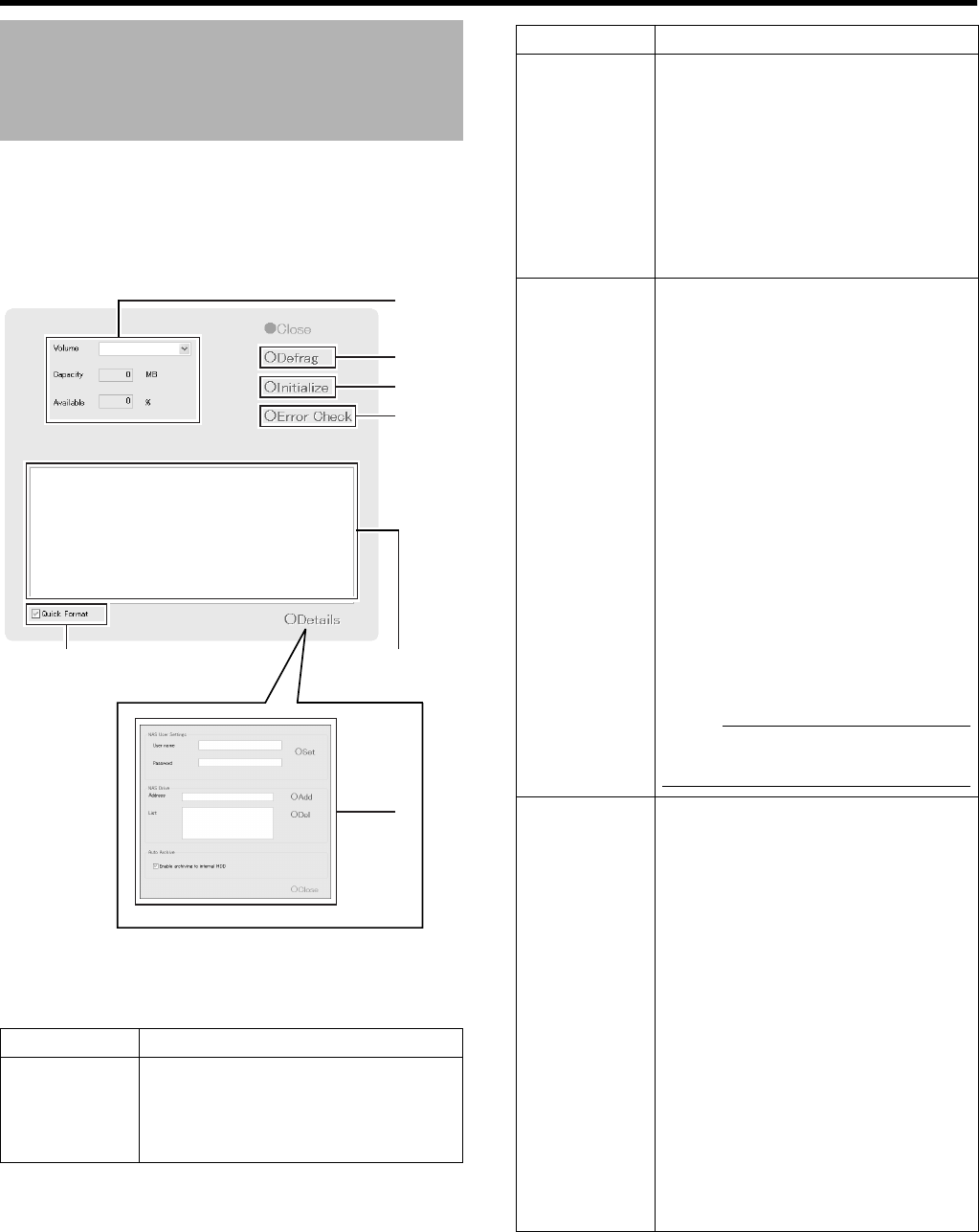
102
Applications
This feature enables you to check the status of the hard disk,
format (initialize), or defragment (eliminate fragmented
space) it.
The [Progress indicator] shows the progress of formatting
and defragmentation.
1 Select [HDD Utility] from the main menu
●The [HDD Utility] screen appears. Specify the following
items.
HDD Utility
Item Description
AVolume Click the Down arrow to the right of the
[Volume] field to select a hard disk.
When you have selected a hard disk, the
capacity and percentage of free space
will appear in the fields below.
B
C
D
F
A
E
[HDD Utility] Screen
[Progress Indicator]
Item Description
BDefrag Executes the defragmentation function
to eliminate fragmented files in the
volume selected in the [Volume] field.
The defragmentation process may take
several hours depending on the status of
the hard disk.
If defragmentation cannot be executed
for some reasons, the “Unable to
perform defragmentation now.” message
will appear. Press [Close] to close the
dialog.
CInitialize Executes initialization of the hard disk
with respect of the volume selected in
the [Volume] field. All data contained in
the volume will be lost after initializing.
You will be asked to confirm whether you
want to format the hard disk. If an
unformatted disk is selected, the
Aunformat diskB or Aunpartition diskB
message will appear.
Click [OK] to start initialization. To
cancel, click the [Cancel] button. If
defragging cannot be executed for some
reason, a message to that effect will be
displayed. Press [OK] or [Cancel] to
close the dialog.
Normally, the hard disk is formatted prior
to shipping, but some types of hard disk
may remain unformatted. In this case,
you will see the [unformat disk] message
in the [Volume] field. For unformatted
disks, select [unformat disk] and press
[Initialize].
Note :
●Volumes C, D, L and M cannot be
initialized.
DError
Check
This is usually not selected. Use it only if
you suspect there is abnormality in the
hard disk, or if you want to check the
data structure of the disk. Recovery of
large-capacity hard disks may take
several hours. Recovery of the hard disk
in the system is impossible. Recovery
will be executed the next time the
system is started.
Recovery may not be possible when the
volume to recover is currently in use. If
this happens, a message will be
displayed informing the user that
recovery cannot be performed at the
present time and asking whether
recovery should be scheduled for the
next time the system is started. Select
whether you want to click the [Cancel]
button and retry by clicking the [Recover]
button again, or whether you want to
click the [OK] button to execute recovery
the next time the system is started.
VR-N1600_J.book Page 102 Wednesday, August 8, 2007 3:32 PM
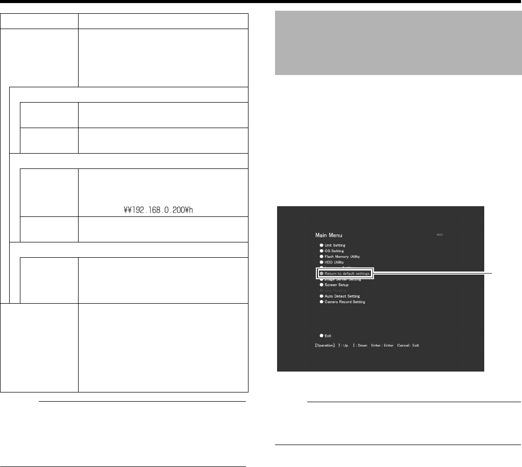
103
Memo :
●NAS is a file server that is connected to the network. You
can specify the NAS as a drive for archiving data using
VR-N1600U/E.
●For details on archiving to the NAS drive, refer to
[Archiving] (A Page 95).
Follow the procedures below to restore the default settings.
1 Select [Return to default setting] from the main
menu
●The [After initializing,the system is automatically
rebooted. Reboot now?] message appears.
2 Click [OK]
●The unit is rebooted after initialization is complete.
Note :
●Settings in the [Password] sections (A Page 62) in [OS
Setting] (A Page 64), [Language Setting], and [Unit
Setting] of the [Main Menu] will not be initialized.
Item Description
EDetails Click this option to display the
[Advanced] screen.
You can specify the settings when
archiving to NAS or the built-in HDD on
this screen.
NAS User Settings
User name For specifying the user name for
connecting to NAS.
Password For specifying the password for
connecting to NAS.
NAS Drive
Add Enter the IP address of the NAS to be
connected to the [Address], and click
the [Add] button.
Example:
Del Select the NAS to delete in [List], and
click the [Del] button.
Auto Archive
Enable
archiving to
internal
HDD
Select this check box.
Data will not be archived to the built-in
HDD if this check box is not selected.
FQuick
Format
Selecting the [Quick Format] check box,
followed by clicking the [Initialize] button
enables you to shorten the time
required for the initialization process.
If bad sectors are found during the HDD
initialization process, deselect the
[Quick Format] check box and press the
[Initialize] button.
Restoring Default Settings
Select
VR-N1600_J.book Page 103 Wednesday, August 8, 2007 3:32 PM
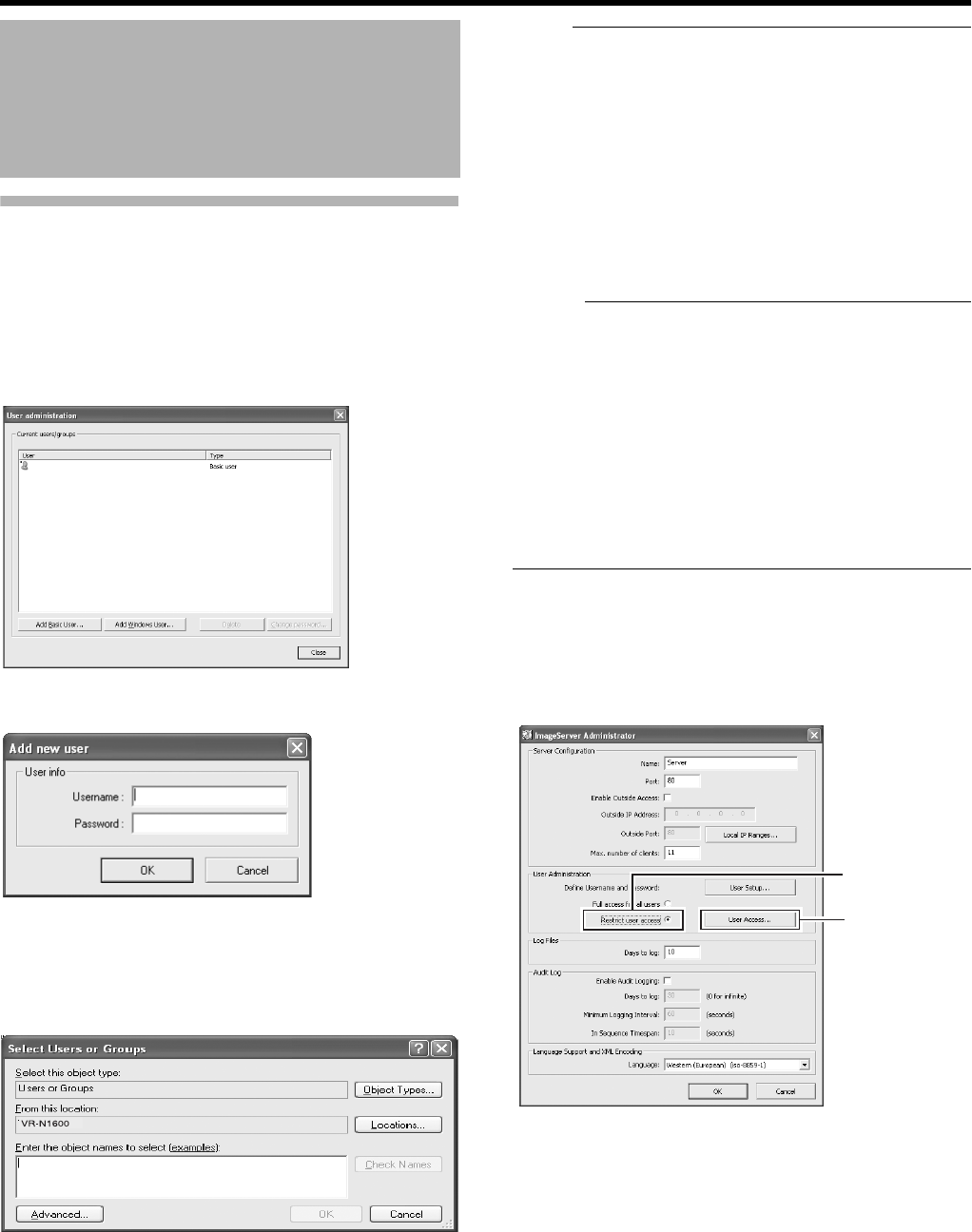
104
Applications
User Administration
This section describes procedures to configure user
accounts and rights.
䡵
User Settings
After the [User Administration] screen appears, you are able
to define individual users and their passwords. There are two
ways to add new users.
䢇Add Basic User...:
You can create a dedicated user account for the
surveillance system through authentication of the user
name and password.
䢇Add Windows User...:
Note :
●Do not select this option. For details, consult your system
administrator.
●If the [Host Name] in [OS Setting] has been changed,
enter AAdministratorB in [Enter the object names to select]
on the [Serect Users or Groups] screen, and click the
[Advanced...] button. Next, click the [OK] button.
●Windows users need to define a Windows user for each
host name specified in [Host Name] in [OS Setting]. As
the user’s host name is not displayed on the [User
Administration] screen, it is recommended that you delete
the Windows user and add again if you have changed the
host name.
Memo :
●To edit a preset user name or password, select the user to
edit from the [Current isers/groups] list, and click the
[Change password...] button.
●To delete a preset user, select the user from the [Current
isers/groups] list, and click the [Delete] button. The user
that has been deleted from the list is no longer able to
login to NVR Viewer.
●After adding a new user in [Add Basic User...], a small
square appears to the top left of the icon on the [User
Administration] screen. You can distinguish between [Add
Basic User...] and [Add Windows User...] using this mark
when the same user name is registered with both.
䡵
Defining User Rights
1 Select [Restrict user access] in the [User
Administration] section
2 Click [User Access...]
Distribution Settings
(Details)
vr-n1600
1
2
VR-N1600_J.book Page 104 Wednesday, August 8, 2007 3:32 PM
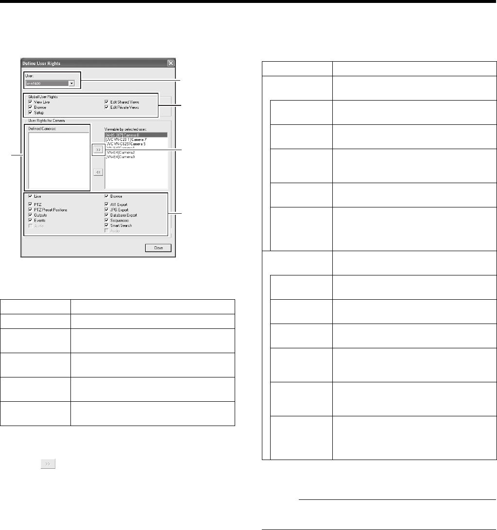
105
3 Select the user for which user right is to be
specified from the [User] list
4 Select the user’s global rights (applicable to all
cameras) in the [Global User Rights] list
5 Select the camera to allow access from the
[Defined Cameras]
6 [Click to move to [Viewable by selected user]
7 Select the functions for each of the cameras that
have been moved to [Viewable by selected user]
●Select the functions from the list of options below. All
options are selected by default.
8 Repeat the same procedures for other users
Memo :
●It is recommended that you limit [Setup] rights to prevent
any inadvertent changes made by system users.
Item Description
View Live Enables you to view live images.
Browse Enables you to play back recorded
images.
Setup Enables you to use the Screen Setup
tab.
Edit Shared
Views
Enables you to create and edit views
within the shared group.
Edit Private
Views
Enables you to create and edit private
views.
3
4
56
7
Item Description
Live Enables you to view live images from the
selected camera.
PTZ Enables you to control the PTZ camera
using the NVR Viewer.
PTZ Presets Enables you to move a PTZ camera to a
preset position using the NVR Viewer.
Outoputs Enables you to trigger outputs such as
by switching on lights and sounding
sirens, if such outputs can be generated.
Events Enables you to trigger manual events
using the NVR Viewer.
Audio Enables you to listen to live audio sound
from the selected camera. (Only when
an audio source is specified for the
camera.)
Browse Enables you to play back recorded
images from the selected camera.
AVI Export Enables you to export images in the AVI
format.
JPG Export Enables you to export images in the
JPEG format.
Database
Export
Enables you to export images and audio
sound in the database format.
Sequence Enables you to use the Sequences
feature to play back images from a
selected camera.
Smart
Search
Enables you to use the Smart Search
feature (A Page 38) using the NVR
Viewer.
Audio Enables you to listen to playback audio
sound from the selected camera. (Only
when an audio source is specified for the
camera.)
VR-N1600_J.book Page 105 Wednesday, August 8, 2007 3:32 PM
106
Applications
The following operations are possible when you connect this
unit to a computer.
●Viewing live images on the computer
●Controlling network cameras on the computer
●Viewing recorded images on the computer
Note :
●Connect the computer to the LAN2 terminal network.
●Settings for cameras connected to the LAN1 network
cannot be specified from a computer connected to the
LAN2 network.
System requirements
Computer Network Settings
The following is an example for building a small-scale LAN
on Windows XP Professional using the default settings of this
unit.
(All screens shown below are Windows XP SP2
configuration screens.)
1 Click the [Start] button, followed by clicking
[Control Panel]
2 Click [Network and Internet Connections]-
[Network Connections]
Connecting to a Computer
Item Description
Operating
System
Microsoft Windows 2000 Professional,
Windows 2000 Server and Advanced
Server, Windows XP Professional (32-
and 64-bit) or Windows Server 2003 (32-
and 64-bit)
CPU Intel Pentium4 or higher (Xeon
recommended for large views), minimum
2.4 GHz
RAM Minimum 512 MB (1 GB recommended
for large views)
Network Ethernet, 100 Mbps or higher
recommended
Graphics Card AGP or PCI-Express, minimum 1024 x
768 (1280 x 1024 recommended), 16-bit
colors or higher
Hard Disk
Space
At least 50 MB free
Software Microsoft. NET Framework 2.0 and
DirectX 9.0 or later versions
Microsoft Internet Explorer 6.0 or later
versions
1
VR-N1600_J.book Page 106 Wednesday, August 8, 2007 3:32 PM
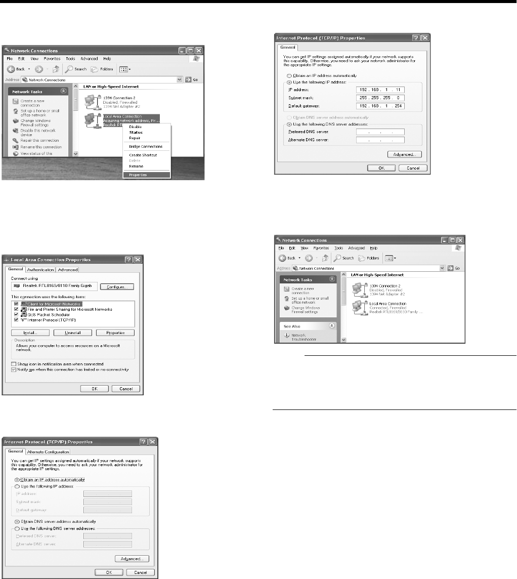
107
3 Select the network to which VR-N1600U/E is
connected
4 Right-click and select [Properties]
5 Check to ensure that both the [Cliant for
Microsoft Networks] and [Internet Protocol
(TCP/IP)] check boxes are selected
6 Select [Internet Protocol(TCP/IP)] and click
the [Properties] button
7 Select [Use the following IP address]
8 Set [IP address] to 192.168.1.11
9 Set [Subnet Mask] to 255.255.255.0
10 Set [Default gateway] to 192.168.1.254
11 Click the [OK] button
12 Click the [OK] button on the [Local Area
Connections Proparties] screen
Note :
●Do not use the same IP address in the same network
environment.
●Do not register multiple IP addresses with one NIC when
specifying the computer network settings.
VR-N1600_J.book Page 107 Wednesday, August 8, 2007 3:32 PM
108
Applications
Install the NVR Viewer on the computer
Note :
●Before installing, check to ensure that Microsoft. NET
Framework 2.0, DirectX 9.0 or later versions, and
Microsoft Internet Explorer 6.0 or later versions are
already installed on the computer. If any of these are not
installed, installation of the NVR Viewer may fail.
1 Open the Internet Explorer browser (6.0 or later
versions), and enter the IP address of VR-
N1600U/E as
Ahttp://192.168.1.253B
●A welcome page will appear.
Note :
●Do not select [Remote Client].
2 Click [Download and install NVR Viewer locally]
●The [Do you want to run or save this files?]
confirmation message appears.
3 Click the [Run] button
Doing so starts up the NVR Viewer Setup Wizard.
4 Click [Next] and follow the installation
instructions
Connecting to a Computer
(continued)
NVR Viewer
NVR Viewsr locally
NVR Viewer.exe
NVR Viewer Installer
NVR_Viewer [1].exe
0848KGYGTH
084
NVR Viewer 1.0f , you
VR-N1600_J.book Page 108 Wednesday, August 8, 2007 3:32 PM
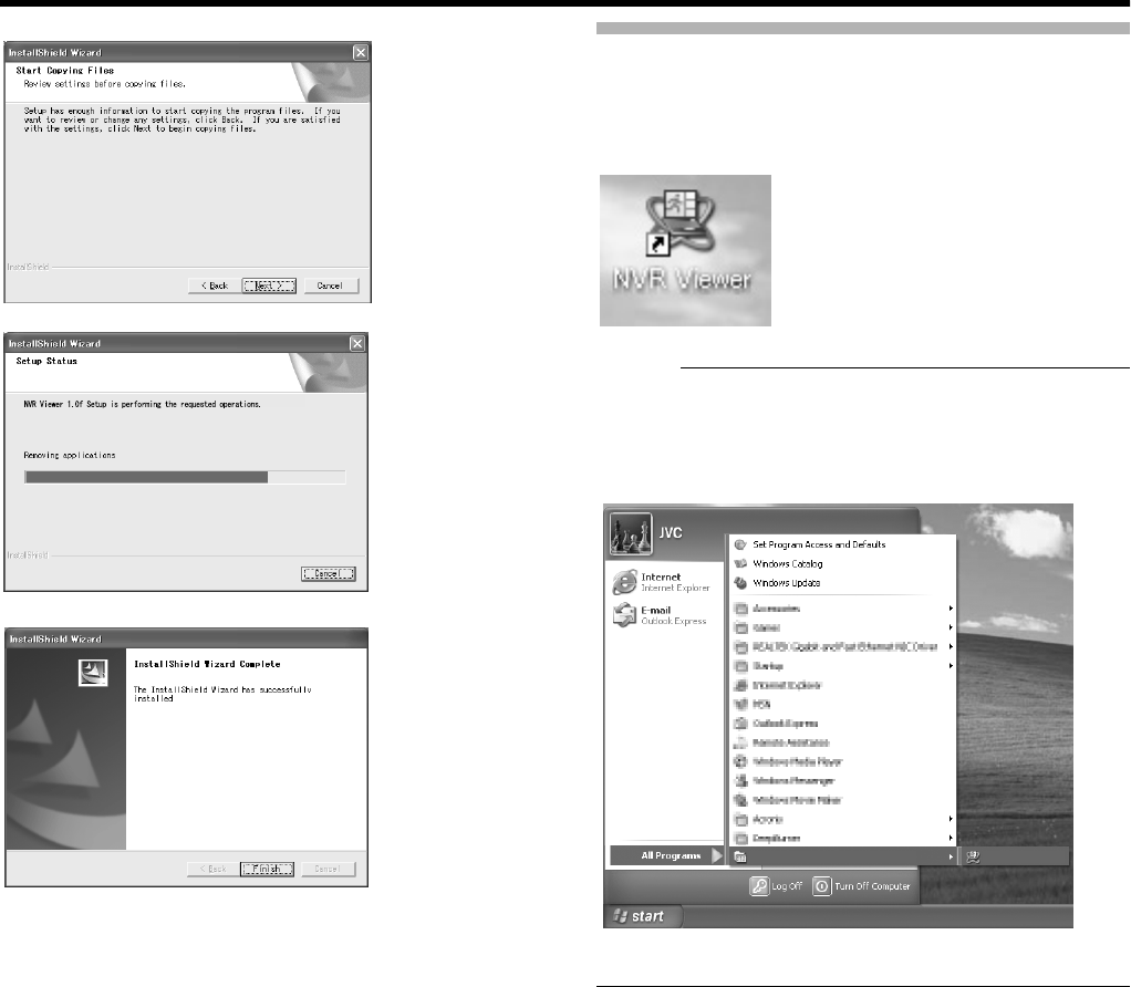
109
5 Installation complete
●Installation ends and a shortcut to the ANVR ViewerB is
created on the desktop.
Login to the NVR Viewer
1 Double-click the NVR Viewer shortcut on the
desktop
Memo :
●If the NVR Viewer shortcut is not found on the desktop,
select ANVR ViewerB from the [Start] menu.
●The NVR Viewer Login screen appears.
0848KGYGTZZ%NKEM(KPKUJVQGZKVVJGYK\CTF
NVR NVR Viewer
VR-N1600_J.book Page 109 Wednesday, August 8, 2007 3:32 PM
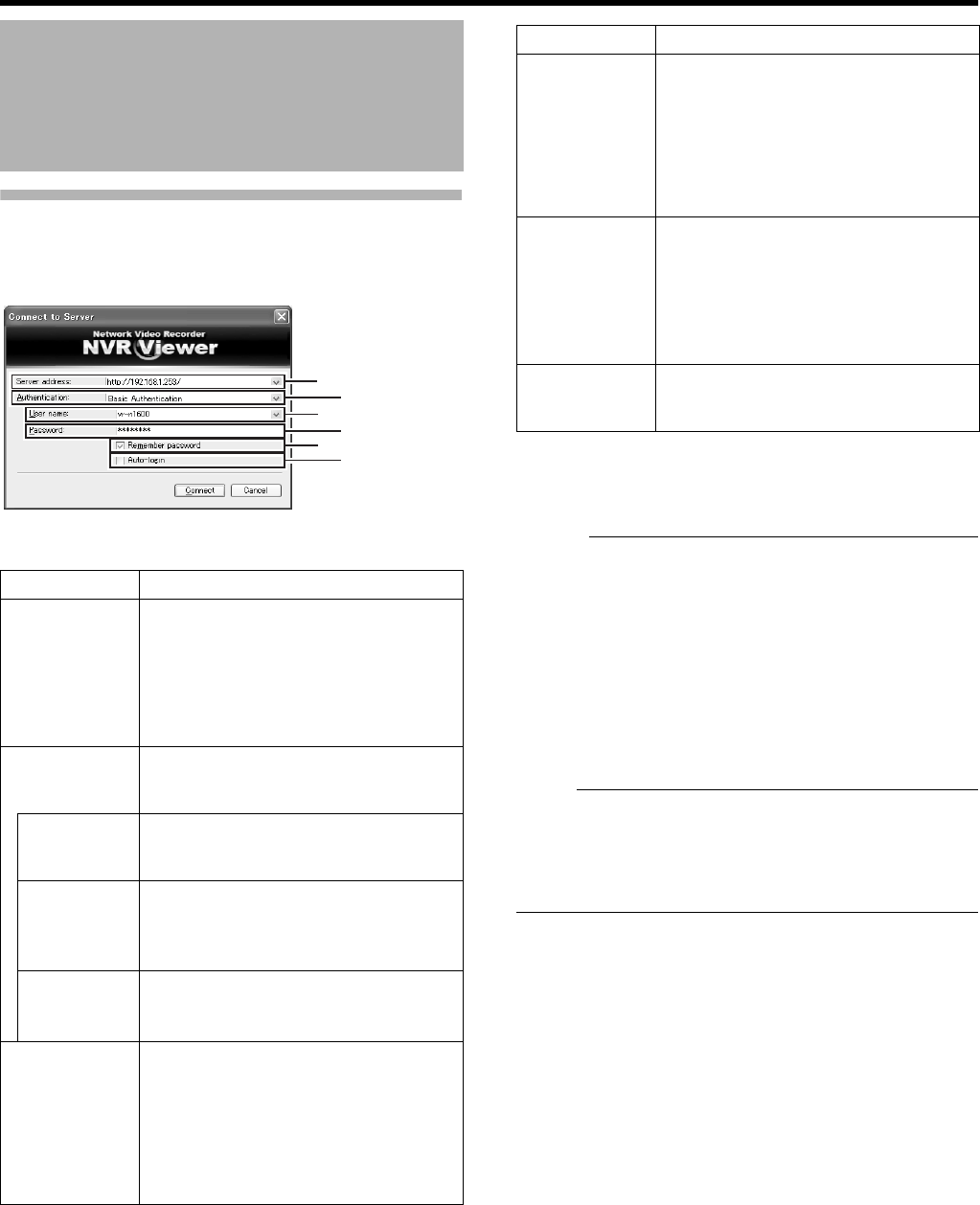
110
Applications
Login to NVR Viewer (Cont’d)
2 Specify your login information in the following
fields
3 Click the [Connect] button
●The NVR Viewer screen appears after a short while.
Memo :
●If you have previously logged in to the NVR Viewer, a
message will appear asking if you want the view that was
used during the last login to be displayed. (Only when
connecting from a surveillance computer)
[Main View]:
Select this check box to restore the view that you last
used in the main window of the [NVR Viewer].
[Detached Views]:
Select this check box to display the views on the [Primary
Display] screen, multi-monitor, or floating screen.
Note :
●When you log out after reaching the maximum number of
distribution clients, you may need to wait for several
minutes before you can establish the connection again.
●When multiple computers are connected and audio sound
is played back, the sound may be distorted.
Connecting to a Computer
(continued)
Item Description
AServer
address
For specifying the IP address and port
number of VR-N1600U/E. (For example,
in the case of [http://192.168.1.253:80],
[:80] is the port number.)
The port number is the number as
specified in [Server Configuration] under
[Image Server Setting]. (A Page 67)
B
Authentication
For selecting one of the three types of
authentication.
Select ABasic authenticationB.
Windows
authentication
(current user)
Windows authentication. Login as the
current Windows user.
Windows
authentication
Windows authentication.
You can login as a Windows user, but a
user name and password will be
required.
Basic
authentication
Basic authentication.
A user name and password will be
required to login to VR-N1600U/E.
C
User name
For entering the Windows user name if
you have selected AWindows
authenticationB for the [Authentication]
item B. For entering the user name
registered in the [User Administration]
item under [Image Server Setting]
(A Page 104) if you have selected
ABasic authenticationB.
A
CD
B
EF
User name: vr-n1600
Password: vr-n1600
Item Description
D
Password
For entering the login password for VR-
N1600U/E if you have selected
AWindows authenticationB for the
[Authentication] item B. For entering the
password registered in the [User
Administration] item under [Image
Server Setting] (A Page 104) if you
have selected ABasic authenticationB.
ERemember
password
Saves the password.
If you have selected AWindows
authenticationB or ABasic
authenticationB for the [Authentication]
item B, selecting this check box enables
you to login the next time simply by
clicking the [Connect] button.
F
Auto-login
Enables you to login automatically.
Selecting the check box enables you to
log into the [NVR Viewer] automatically.
VR-N1600_J.book Page 110 Wednesday, August 8, 2007 3:32 PM
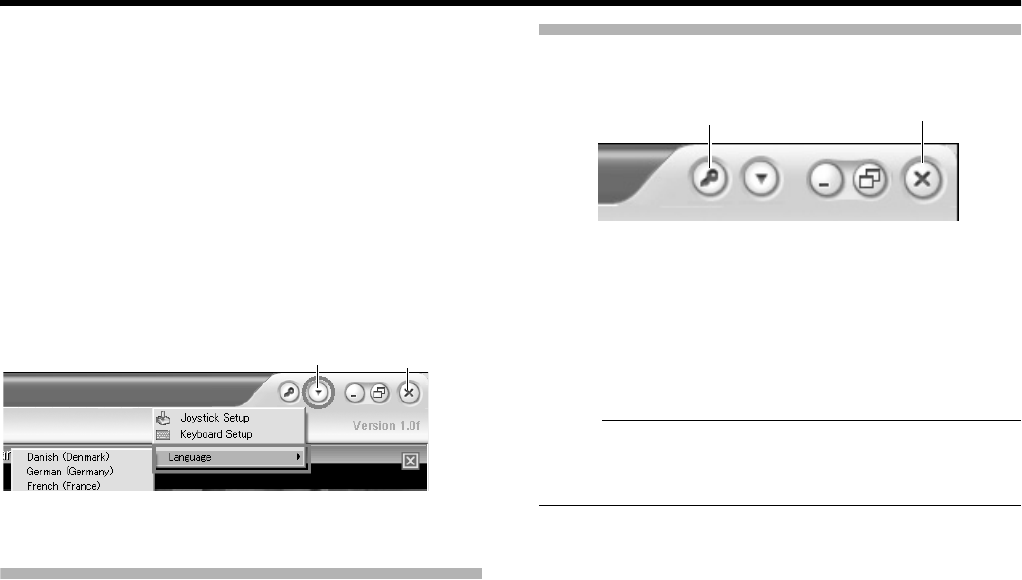
111
4 Setting the Display Language According to the
Country of Use
AClick the [K] button at the top right corner of the
screen.
BSelect [Language] from the menu that appears.
CSelect the language for the country of use from the
displayed sub-menu.
DClick [OK] when the dialog appears.
EClick the [⳯] button at the top right corner to exit the
NVR Viewer.
hThe selected language will be enabled during the
next startup.
Uses of the NVR Viewer
For uses of the NVR Viewer, refer to the following pages.
䢇[Viewing Live Images via Mouse Control] (A Page 28)
䢇[Playing Back Recorded Images via Mouse Control] (A
Page 34)
䢇[Screen Setup] (A Page 54)
Exiting/Logging Out of the NVR Viewer
䡵
Logging Out
1 Click the [Log Out] button
●You are logged out and the Login screen of the NVR
Viewer appears again.
Note :
●If you have rebooted the VR-N1600U/E or NVR Viewer
unit, log out from the NVR Viewer on the surveillance PC
once, and login again.
䡵
Exiting
1 Click the [⳯] button
●Ends the NVR Viewer.
[K] Button [⳯] Button
[Log Out] Button [⳯] Button
VR-N1600_J.book Page 111 Wednesday, August 8, 2007 3:32 PM
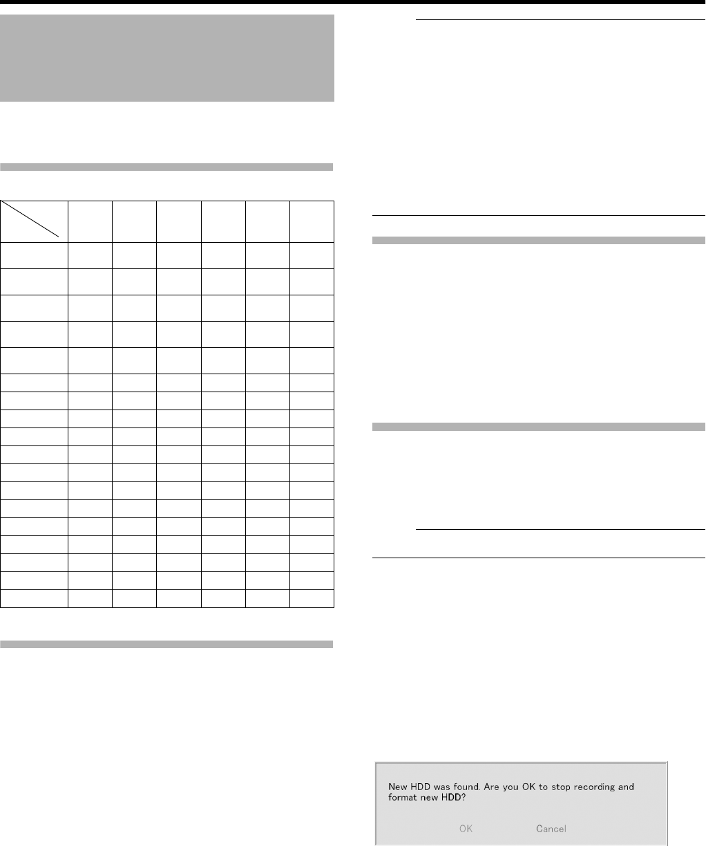
112
Others
Use peripheral devices according to the requirements on the
environment of use for the respective devices.
Compatible Network Cameras
Connecting a UPS
Connecting an uninterruptible power supply (UPS) to the
hard disk will protect it from damage by automatically
shutting down all operations prior to switching off the power
supply in the event of a power failure.
1 Connect the UPS communication cable to the
[SERIAL] port on the rear panel
2 Connect the power cable of this unit to the UPS
power output connector
3 Switch on the power of the UPS, followed by the
power of this unit
Note :
●Consult your nearest JVC dealer for details on the types
of UPS that can be used.
●Make sure that the UPS communication cable is
connected before switching on the power of this unit.
●Do not disconnect the communication cable when
operations are in progress.
●When a power failure occurs while formatting a hard disk
or archiving, subsequent operation may be affected even
when an UPS is connected.
●The recorded images may not be played back properly if
they are not archived before the power failure. (A Page
97)
External Hard Disk Drives
You can connect an external hard disk to the serial port
located on the rear side of this unit. You can combine
external hard disk drives with this unit in the following ways.
Combinations other than those below are not possible.
●500 GB (1 unit)
●1 TB (1 unit)
●1 TB (1 unit) + 2 TB (1 unit)
●2 TB (1 unit)
●2 TB (up to 2 units)
Connecting an External Hard Disk Drive
1 Press and hold the [OPERATE] button for about
2 seconds to turn the operation off
2 Turn off the power switch on the rear panel
Note :
●Make sure that you turn off the power switch.
3 Connect the external hard disk drive to the
[SERIAL] port on the rear panel, and switch on
the power
●Make sure that you switch on the power to the external
hard disk drive before switching on this unit. The
system may not recognize the external drive unless it
has been switched on beforehand.
4 Switch on the power of this unit
●If recording is in progress, a [New HDD was found. Are
you OK to stop recording and format new HDD?]
confirmation message appears.
●Click the [OK] button to automatically start up the HDD
Utility. (A Page 102)
●The confirmation message will only appear during
recording.
Compatible Equipment
Function JPG PTZ Audio PTZ
Joystick
MPG4 VMD
Event
Network
Camera
JVC
VN-C20 ●
JVC
VN-C655 ●● ●
JVC
VN-C625 ●● ●
JVC
VN-E4 ●●●●
JVC
VN-C215 ●
AXIS 206 ●
AXIS 207 ●●●
AXIS 211 ●●●●
AXIS 212 ●●●●●●
AXIS 213 ●●●●●●
AXIS 214 ●●●●●●
AXIS 216 ●●●●
AXIS 225 ●●●
Verint S1700 ●●●
Verint S1704 ●●●
Verint S1708 ●●●
Verint S1900 ●
Verint S2700E ●
VR-N1600_J.book Page 112 Wednesday, August 8, 2007 3:32 PM
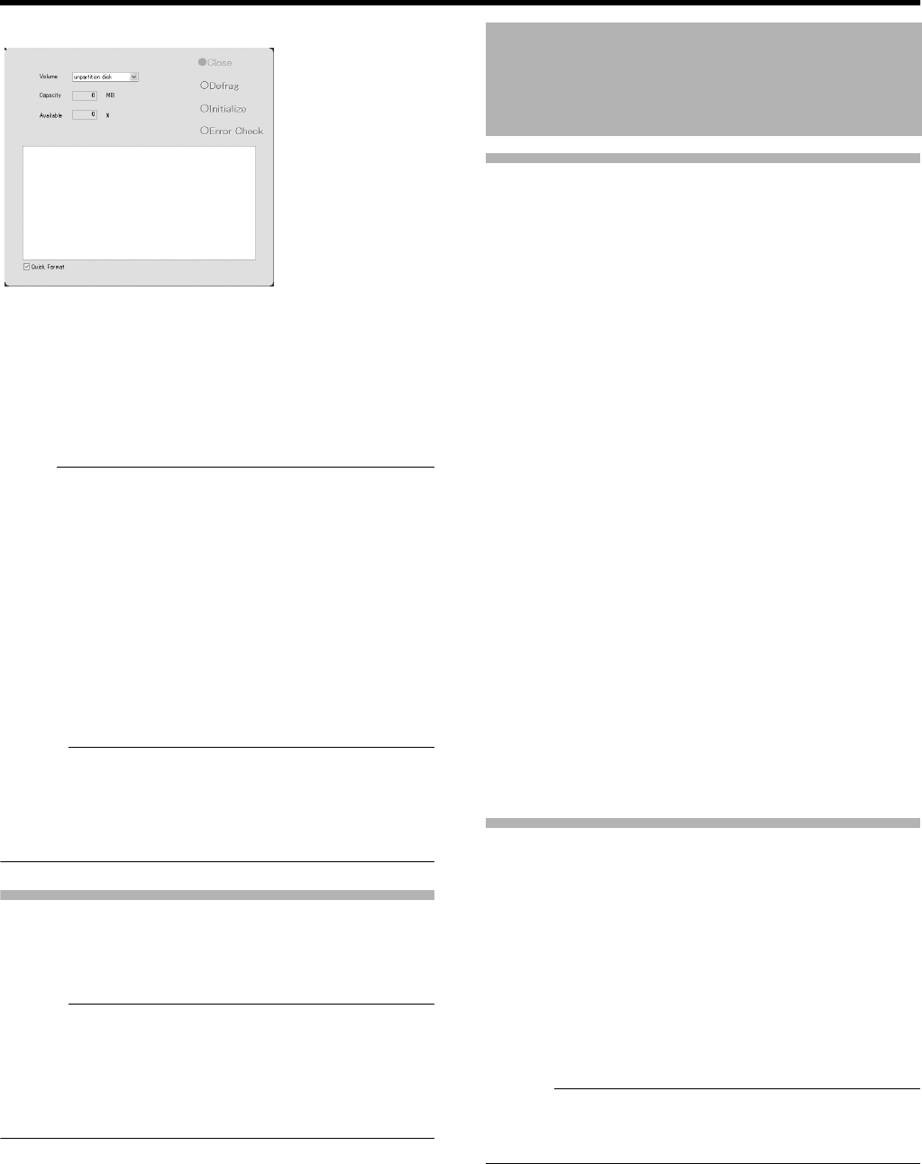
113
5 Check the entry in the [Volume] field, and click
the [Initialize] button
●The external hard disk drive is initialized.
●Check to ensure that the [Volume] field is set to
[unformat disk], [unpartition disk] and [unknown
partition]. Selecting any other volume may result in the
deletion of recorded data.
Note :
●Consult your nearest JVC dealer for details on the type of
external hard disk drive that can be used.
●When an additional hard disk is connected, over ten
seconds of the recorded image may be lost during
archiving.
●Note that if playing back video recorded in an external
HDD simultaneously on VR-N1600U/E and by multiple
clients may slow down playback of video images and
audio sound.
This is not a malfunction and there is no problem with the
recorded images. Normal playback will be restored when
simultaneous playback stops or when the number of
devices playing back at the same time decreases.
Memo :
●It is recommended that a UPS be used to ensure stable
operation of the system.
●You are unable to view recorded images on the computer
by disconnecting the external hard disk from this unit and
connecting it to the computer.
NAS
NAS is a file server that is connected to the network.
You can specify the NAS as a drive for archiving data using
VR-N1600U/E.
Memo :
●For settings on this unit when you are using NAS, refer to
[Archiving] (A Page 95) and [HDD Utility] (A Page 102).
●Follow the instructions in the NAS [Instruction Manual] for
configuration of NAS settings. It may take a while before
formatting or RAID settings can be completed. For details,
consult the NAS manufacturer.
Combining a Button with the [FUNCTION] Button
䡵[FUNCTION] +[REC CONTROL]
Displays the main menu.
(APage 24 [Opening the Main Menu])
䡵[FUNCTION] +[LIVE/BROWSE]:
Reboots the NVR Viewer and internal distribution server.
(A Page 25)
䡵[FUNCTION] +[KEY]
Locks/Unlocks the panel operation.
(APage 13 [Operation Lock])
䡵[FUNCTION] +[1]
Displays/Hides the performance meter.
(APage 19 [Performance Meter]))
䡵[FUNCTION] +[2]
Displays/Hides the clock.
(APage 19 [Clock Display])
䡵[FUNCTION] +[4]
For use when writing data to a CD-R.
(APage 41 [Burning a CD(Operate from the VR-N1600U/
E unit)])
䡵[FUNCTION] +[5]
For controlling the PTZ camera.
(APage 114 [PTZ Camera Control])
䡵[FUNCTION] +[6]
Displays the maintenance information screen.
(APage 116 [Display and Saving of Maintenance
Information])
Pressing a Button for Two Seconds or Longer
䡵[REC CONTROL]
Turns on/off the recording control mode.
[Selecting the Recording Control Mode] (A Page 47)
䡵[ALARM CLEAR]
The light of the [WARNING] indicator goes off.
(APage 126 [Actions when Warning Indicator Lights Up])
䡵[FUNCTION] +[LIVE/BROWSE]
Logs out of the system.
Memo :
●When [Auto Logon] is enabled, the login operation starts
automatically immediately after logging out. (APage 62
[Unit Setting])
䡵[FUNCTION] +[OPERATE]
Shuts down the system forcibly.
Special Key Operations
VR-N1600_J.book Page 113 Wednesday, August 8, 2007 3:32 PM
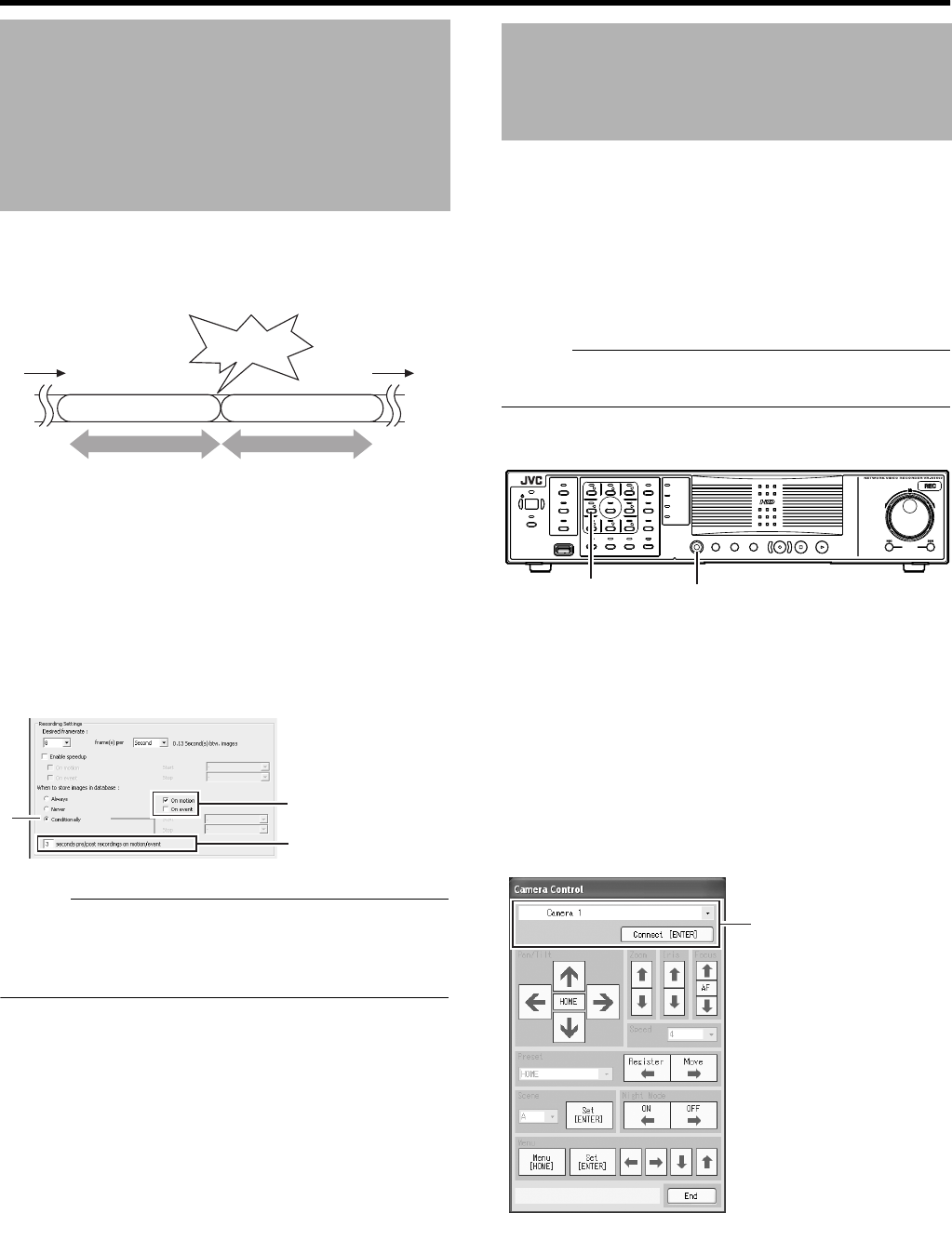
114
Others
You can record images before and after the occurrence of an
event or motion when recording in the recording control
mode (A Page 47).
1 Go to [Settings] (A Page 50), and select
AConditionallyB in [Recording Settings]-[When
to store images in database]
2 Select AOn motionB or AOn eventB
3 Specify the number of seconds in [( )seconds
pre/post recordings on motion/event]
●Images are recorded during the specified time interval
before and after an alarm or motion is detected.
Memo :
●Sequences refers to sequences of images that are
recorded when an event or motion is detected.
●For details on using sequences, refer to [Searching
Recorded Image Using Sequence] (A Page 37).
Connecting the PTZ camera to the COM port of the network
encoder (VN-E4) enables the PTZ control on the live screen
of the NVR Viewer. For details on PTZ camera settings, refer
to [PTZ Camera Settings (COM1/COM2)] (A Page 76).
For cameras that have specified the [JCBP-S] protocol in AP/
T/Z type controlled through COM1/COM2B of [PTZ Camera
Settings (COM1/COM2)], control of the iris, focus and
camera menu are also enabled on the live screen of the NVR
Viewer in addition to PTZ control.
Memo :
●A PTZ camera is an analog camera with an analog output
that enables PTZ control via RS-485.
1 Press and hold the [FUNCTION] button, and
press the [5] keypad button at the same time
●The [Camera Control] screen appears.
2 Select the camera you want to control from the
camera selection list, and click the [Set
(ENTER)] button
●Camera control is enabled.
●The functions of the buttons are described below.
Recording Before/After
Occurrence of Event or
Motion
Stopped Stopped
Motion or event
Records for set time before Records for set time after
Set time Set time
1
2
3
PTZ Camera Control
OPERATE
REC CONTROL
LIVE/BROWSE
SELECT
PTZ/PRESET
SERIAL
㧝 㧞 㧟 㧠
㧡 㧢*1/' 㧣
㧥
㧤
CANCEL ZOOM OUT ZOOM IN ENTER
WARNING
ALARM
HDD
LOCK
SEARCHFUNCTION ALARM CLEARKEY REC/STOP STOP(PB) PLAY
SKIP
REV FWD
[5] Button [FUNCTION] Button
2
[NVR]
VR-N1600_J.book Page 114 Wednesday, August 8, 2007 3:32 PM
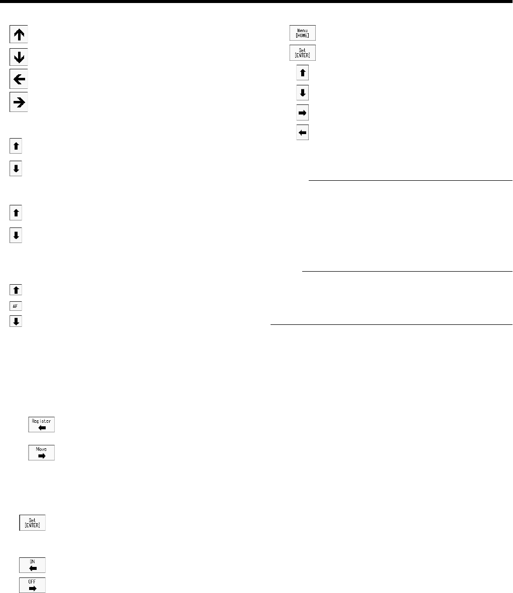
115
䡵
Pan/Tilt
䡵
Zoom
䡵
Iris
䡵
Focus
䡵
Speed
For setting the movement speed of the PTZ action to eight
different levels. (1 represents the slowest speed)
䡵
Preset
䡵
Scene
䡵
Night Mode
䡵
Menu
䡵
Exit
Exits PTZ camera control
Memo :
●You can use the [SKIP] buttons to change the item to
control.
●You can also use the cursor buttons on the keypad to
control movement in the direction indicated by the
respective buttons.
●You can use the [13/CANCEL] button to exit the PTZ
camera control mode.
Note :
●If you are unable to establish connection with the camera
by clicking the [Set(ENTER)] button, try again after
stopping and rebooting the recording server. (APage 73
[Service Manager...])
: Tilts the camera upwards
: Tilts the camera downwards
: Pans the camera to the right
: Pans the camera to the left
: Zooms out
: Zooms in
: Opens the iris
: Closes the iris
: Sets the focus to a distant position
: Focuses automatically
: Sets the focus to a closer position
Position
Selection :For selecting HOME or any position
between 1 to 50.
:For moving to the position selected
using Position Selection
:
For registering a position selected
using Position Selection as the current
position
Scene
Selection : For selecting a scene between A to H.
:For setting a scene selected using Scene
Selection
: Turns on the night mode
: Turns off the night mode
: Displays the PTZ camera menu
: Selects the PTZ camera menu
: PTZ camera’s menu (Up cursor)
: PTZ camera’s menu (Down cursor)
: PTZ camera’s menu (Right cursor)
: PTZ camera’s menu (Left cursor)
VR-N1600_J.book Page 115 Wednesday, August 8, 2007 3:32 PM
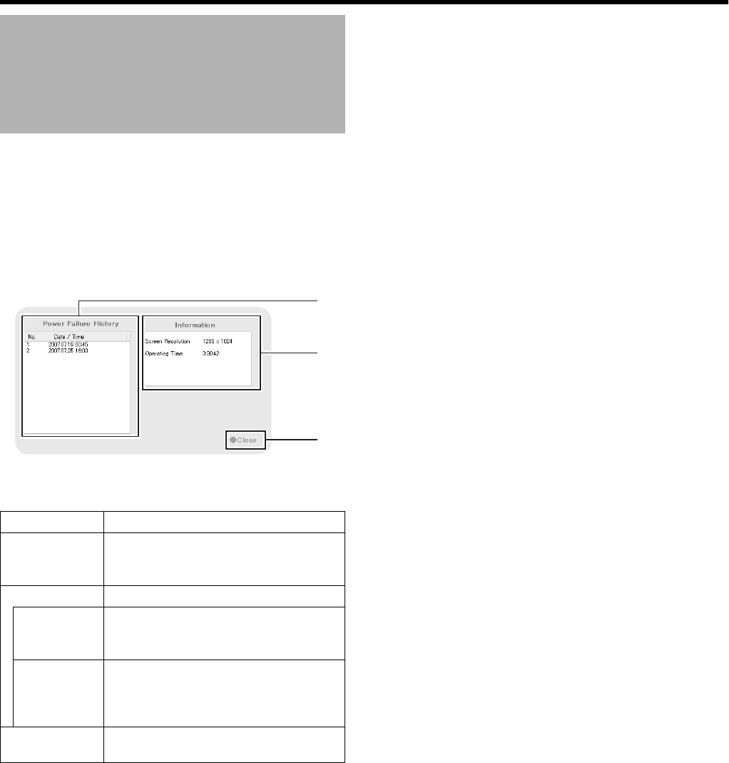
116
Others
This section describes procedures for displaying various
information.
1 Press and hold the [FUNCTION] button, and
press the [6/HOME] keypad button at the same
time
●The [Maintenance Information] screen appears.
Display and Saving of
Maintenance Information
Item Description
APower
Filure
History
The power failure history appears. The
[Power Filure History] is empty if no
power failure has occurred in the past.
BInformation
Screen
Resolution
Displays the screen resolution.
This is expressed in units of Avertical
pixel x horizontal pixelB.
Operating
Time
Displays the total operating time of VR-
N1600U/E.
This is expressed in the
Ahours:minutes:secondsB format.
CClose Closes the [Maintenance Information]
screen.
A
B
C
VR-N1600_J.book Page 116 Wednesday, August 8, 2007 3:32 PM
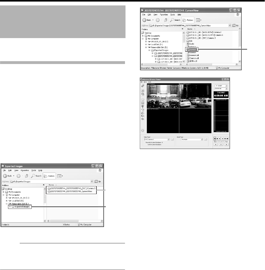
117
You can view data exported to a USB memory device or CD-
R/RW on the computer.
Starting the Export Viewer
1 Insert the USB memory device containing the
exported data into the USB port of the computer
●The USB memory device is automatically recognized
by the computer as a removable disk.
2 Go to the Start menu, and select [Windows
Explorer] in [All Programs]-[Accessories]
●The [Windows Explorer] appears. 22
3 Select the [Exported Images] folder in the
removable disk from the folder list in the
Explorer.
●The exported folder appears on the list on the right.
Memo :
●The name of the exported folder is indicated as follows.
The date of the folder name indicates the exported date.
●[YYYYMMDDhhmmss_YYYYMMDDhhmmss] _
[Camera Model] Camera name.
4 Double-click the data folder in the list on the
right side of the Explorer
●A file list appears in the right list.
5 Double-click [Browser.exe] in the list on the right
side of the Explorer
●The Export Viewer starts up.
Export Viewer
******
******
******
******
******
Select
List
Double-
click
[Milestone XProtect Viewer] Screen
VR-N1600_J.book Page 117 Wednesday, August 8, 2007 3:32 PM
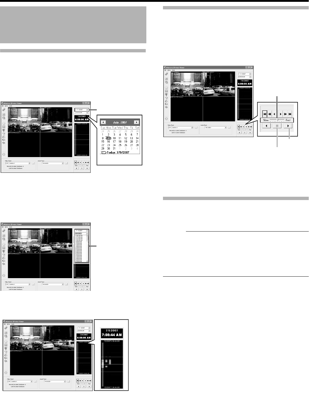
118
Others
Viewing Exported Data
䡵
Viewing Data on a Specific Date/Time Using Date/
Time Selection
1 Click the [K] button for date selection
●A calendar appears.
2 Select a specific date from the calendar
●Image on the selected date appears.
3 Click the [K] button for time selection, and
select a specific time
●Image of the selected time appears.
䡵
Viewing Data on a Specific Date/Time Using Timeline
The vertical timeline indicates the progress status of a
recording operation.
1 Drag the mouse pointer upwards or downwards
on the Timeline
●You can view data at the specified date/time while
checking the images.
Data Playback/Stopping Data Playback
䡵
Playback
1 Set the playback speed using the speed control
2 Click the Play button
●The data base is played back at the specified speed.
䡵
Stopping Playback.
1 Click the Stop button
●Data playback stops.
Exiting the Export Viewer
1 Go to the Start menu, and select [File]-[Close]
●Ends the Export Viewer.
Memo :
●You can also click [⳯] on the right side of the screen to
exit the Export Viewer.
●For details on the viewer, refer to the XProtect Enterprise
6.0 Monitor & Viewer User’s Manual provided by
Milestone Systems. (http://www.milestonesys.com/
?cid=265)
Export Viewer (continued)
Click
Calendar
Click
Timeline
Speed Control
Play Button
Stop Button
VR-N1600_J.book Page 118 Wednesday, August 8, 2007 3:32 PM
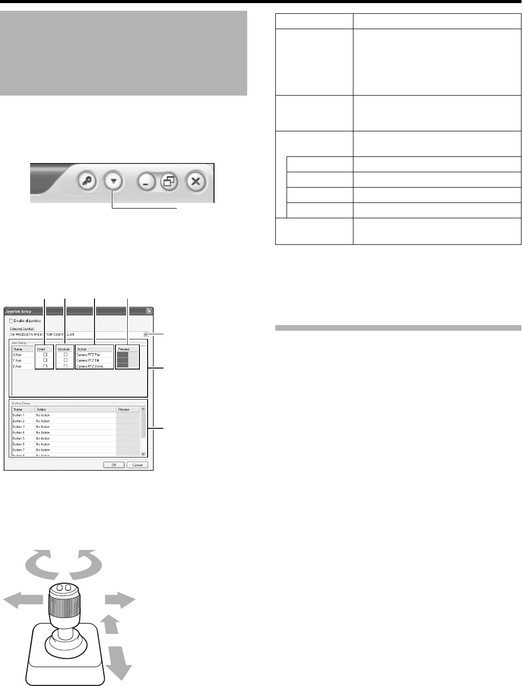
119
1 Click the [K] button at the top right corner of the
screen
2 Select [Joystick Setup] from the menu that
appears
3 Select a joystick from the selected joystick list
4 Specify the settings for each axis in the [Axis
Setup] section
5 Assign an action to each joystick button in the
[Button Setup] section
●Select the action to assign in the [Action] field.
Disabling Joystick Operation
To disable the joystick operation, select the [Disable all
joysticks] check box.
Customizing Joystick
Settings
[K] Button
AB C D
[Joystick] List
[Axis Setup] Section
[Button Setup] Section
Z-axis
Y-axis
X-axis
Joystick
Item Description
AInvert By default, the PTZ camera moves to
the right when you push the joystick to
the right along the X-axis, and moves
up when you pull the joystick towards
you along the Y-axis. The movements
are reversed if you select [Invert].
BAbsolute By selecting AAbsoluteB, the angle of
the joystick corresponds to the direction
of the camera.
CAction For specifying the action when you
move the joystick.
PTZ Pan Moves the camera horizontally
PTZ Tilt Moves the camera vertically
PTZ Zoom Zooms in or zooms out the camera
No Action No action
DPreview
Image
You can check how each camera
moves on each axis with the joystick.
VR-N1600_J.book Page 119 Wednesday, August 8, 2007 3:32 PM
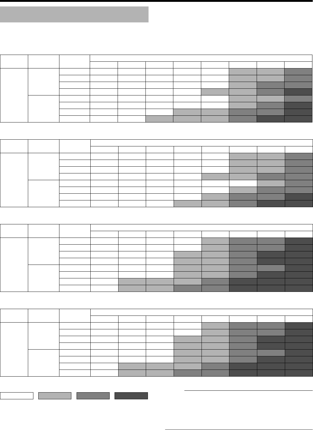
120
Others
The actual recording time varies according to the camera settings, input image content, and condition of the hard disk.
Use the tables below as a guide to the recording time.
Note :
●Recording time may be shortened by approximately 10 %
according to the condition of the hard disk and the images
recorded.
●Recording time may be shortened due to aging of the
hard disk.
Recording Time Schedule
䢇16 Channel Recording/No Audio Recording/No Additional HDD
[Hour]
Image
Size
Data/Image
[kB]
Frame rate per channel, per second [ips]
30 15 10 5 3 1 0.5 0.2
Picture
Quality
Settings
VGA 32.0 ^14 22 43 72 223 470 1211
24.0 ^20 30 60 100 305 635 1623
20.0 ^24 37 73 122 371 767 1953
16.0 ^31 46 93 155 470 964 2447
QVGA 27.0 ^18 26 53 88 269 561 1439
15.0 ^33 50 99 166 503 1029 2609
8.0 ^64 96 191 319 963 1951 4913
5.0 ^103 155 310 517 1556 3136 7875
䢇16 Channel Recording/2 Channel Audio Recording/No Additional HDD
[Hour]
Image
Size
Data/Image
[kB]
Frame rate per channel, per second [ips]
30 15 10 5 3 1 0.5 0.2
Picture
Quality
Settings
VGA 32.0 ^14 22 43 72 216 441 1044
24.0 ^20 30 59 98 292 584 1339
20.0 ^24 36 72 120 353 695 1557
16.0 ^31 46 92 151 441 855 1859
QVGA 27.0 ^17 26 52 86 258 521 1210
15.0 ^33 49 98 162 470 905 1951
8.0 ^63 95 187 306 854 1556 3014
5.0 ^102 152 298 484 1293 2233 3926
䢇16 Channel Recording/No Audio Recording/Additional HDD (1 TB ⳯ 1 Unit)
[Hour]
Image
Size
Data/Image
[kB]
Frame rate per channel, per second [ips]
30 15 10 5 3 1 0.5 0.2
Picture
Quality
Settings
VGA 32.0 ^49 74 148 247 747 1519 3833
24.0 ^67 100 200 333 1004 2033 5118
20.0 ^80 120 241 401 1210 2444 6147
16.0 ^101 151 303 504 1519 3061 7689
QVGA 27.0 ^59 88 177 295 890 1804 4547
15.0 ^108 162 323 538 1621 3267 8203
8.0 ^204 306 611 1018 3061 6147 15402
5.0 ^327 491 981 1635 4912 9849 24658
䢇16 Channel Recording/2 Channel Audio Recording/Additional HDD (1 TB ⳯ 1 Unit)
[Hour]
Image
Size
Data/Image
[kB]
Frame rate per channel, per second [ips]
30 15 10 5 3 1 0.5 0.2
Picture
Quality
Settings
VGA 32.0 ^49 74 147 244 724 1428 3311
24.0 ^66 99 198 328 963 1875 4232
20.0 ^80 120 238 395 1151 2220 4912
16.0 ^100 150 299 494 1428 2718 5853
QVGA 27.0 ^59 88 175 291 858 1678 3833
15.0 ^107 160 319 527 1519 2880 6147
8.0 ^202 302 596 977 2718 4912 9469
5.0 ^323 481 943 1533 4090 7028 12317
Recording time in the chart is calculated based on recording in the JPEG format.
24 to 168 169 to 720 721 to 2160 2161 or over
1 day to 1 week 1 week to 1
month
1 month to 3
months
3 months or
longer
VR-N1600_J.book Page 120 Wednesday, August 8, 2007 3:32 PM
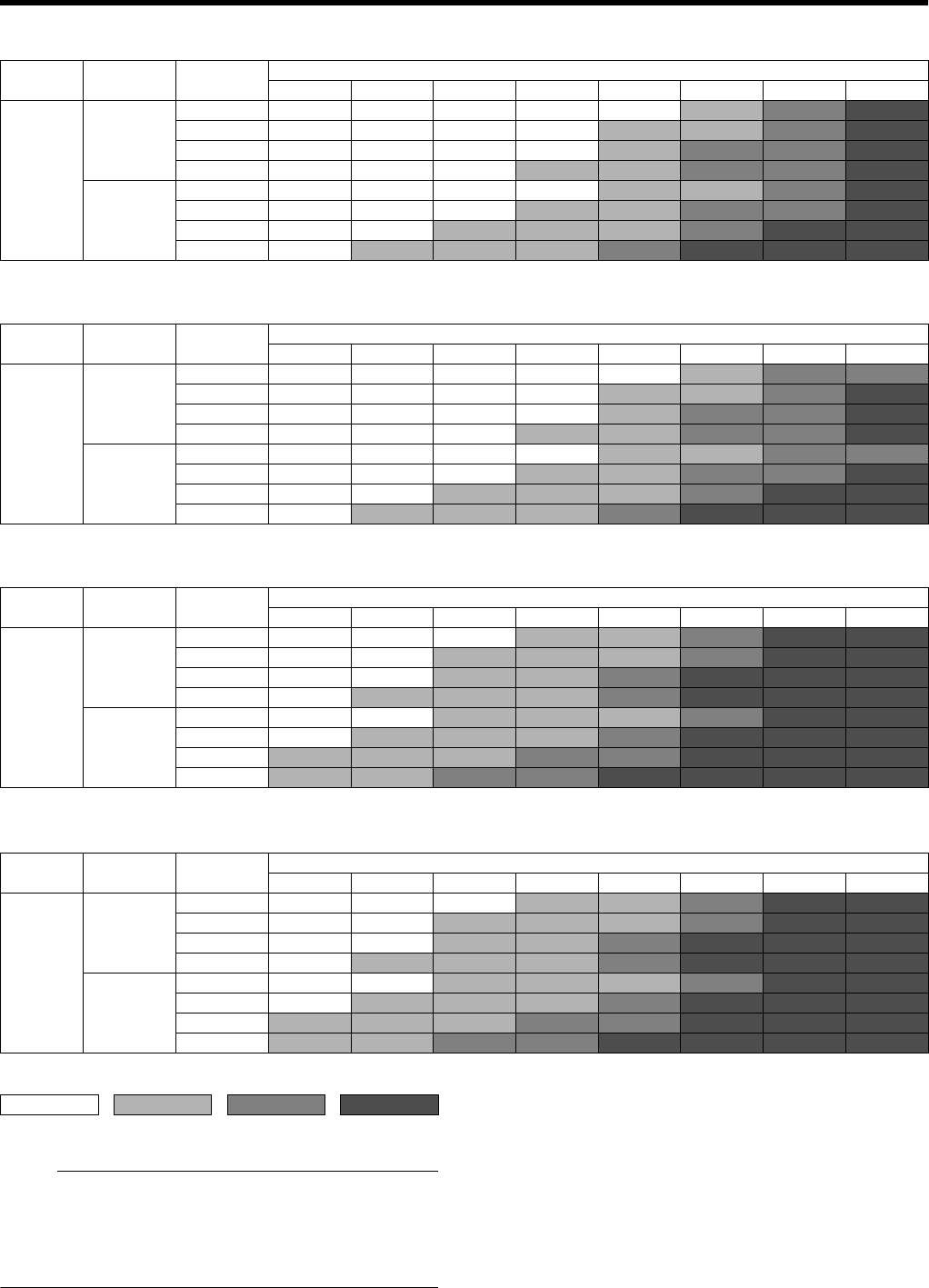
121
Note :
●Recording time may be shortened by approximately 10 %
according to the condition of the hard disk and the images
recorded.
●Recording time may be shortened due to aging of the
hard disk.
䢇8 Channel Recording/No Audio Recording/No Additional HDD
[Hour]
Image
Size
Data/Image
[kB]
Frame rate per channel, per second [ips]
30 15 10 5 3 1 0.5 0.2
Picture
Quality
Settings
VGA32.015314693155
470 964 2446
24.0 21 42 63 126 210 635 1293 3269
20.0 25 51 76 152 253 766 1557 3928
16.0326496
192 319 964 1952 4916
QVGA 27.0 19 37 56 111 185 562 1147 2904
15.0 34 68 102 205 341 1030 2084 5246
8.0 65 130 194 389 648 1685 3925 9847
5.0 104 209 313 626 1044 3138 6299 15785
䢇8 Channel Recording/2 Channel Audio Recording/No Additional HDD
[Hour]
Image
Size
Data/Image
[kB]
Frame rate per channel, per second [ips]
30 15 10 5 3 1 0.5 0.2
Picture
Quality
Settings
VGA32.015314692151
441 854 1858
24.0 21 42 62 124 204 584 1105 2301
20.0 25 50 75 149 245 695 1293 2611
16.0326395
187 306 854 1557 3016
QVGA 27.0 18 37 55 109 180 521 996 2112
15.0 34 68 101 199 326 906 1640 3138
8.0 64 128 190 370 598 1557 2611 4367
5.0 103 203 301 580 920 2234 3489 5246
䢇8 Channel Recording/No Audio Recording/Additional HDD (1 TB ⳯ 1 Unit)
[Hour]
Image
Size
Data/Image
[kB]
Frame rate per channel, per second [ips]
30 15 10 5 3 1 0.5 0.2
Picture
Quality
Settings
VGA 32.0 50 101 151 303 504 1519 3061 7689
24.0 68 135 203 405 676 2033 4089 10259
20.0 81 163 244 488 813 2444 4912 12316
16.0 102 204 305 611 1018 3061 6146 15401
QVGA 27.0 60 120 180 360 599 1804 3632 9117
15.0 109 217 326 652 1087 3267 6557 16429
8.0 205 409 614 1228 2047 6146 12316 30826
5.0 328 656 984 1968 3281 9848 19720 49336
䢇8 Channel Recording/2 Channel Audio Recording/Additional HDD (1 TB ⳯ 1 Unit)
[Hour]
Image
Size
Data/Image
[kB]
Frame rate per channel, per second [ips]
30 15 10 5 3 1 0.5 0.2
Picture
Quality
Settings
VGA 32.0 50 100 150 299 494 1428 2718 5852
24.0 67 134 201 399 657 1874 3502 7235
20.0 81 161 241 478 786 2220 4089 8203
16.0 101 202 302 596 977 2718 4912 9468
QVGA 27.0 60 119 178 354 585 1678 3161 6648
15.0 108 215 322 635 1040 2880 5172 9848
8.0 203 403 599 1169 1888 4912 8203 13687
5.0 324 639 946 1822 2894 7027 10945 16429
Recording time in the chart is calculated based on recording in the JPEG format.
24 to 168 169 to 720 721 to 2160 2161 or over
1 day to 1 week 1 week to 1
month
1 month to 3
months
3 months or
longer
VR-N1600_J.book Page 121 Wednesday, August 8, 2007 3:32 PM

122
Others
Default Value List
Scheduler [Scheduler Setting] (A Page 47) [ ] : Factory Settings
Online [Always Online]
Enable speedup [Always Offline]
E-mail [Always Offline]
Patrolling [Always Offline]
Camera Settings [Edit Device...]^[Settings] (A Page 50)
PTZ Camera Section
Some of the connected cameras are Pna/Tilt/Zoom cameras [Not Selected]
Camera Type [Fixed]
Camera Settings [Specifying Image Recording Settings] (A Page 49)
Speedup Settings
Frame Rate [8]
Frame/ [Sec.] /Min. /Hour
Recording Settings
Desired framerate [8]
Frame/ [Sec.] /Min. /Hour
Enable speedup [Not Selected]
When to store images in database Always /Never /[Conditionally]
On motion [Selected]
On event [Not Selected]
( )seconds pre/post recordings on motion/event
Live Settings (A Page 50)
Desired framerate
Same as recording [Not Selected]
Same sa speedup [Selected]
Database Settings [Database Settings] (A Page 96))
Max.records in database [Selected] [108000]
Maxtimespan in database [Not Selected]
Archive automatically when database is full [Selected]
In case of database failure the following action syould be taken Repair,Scan,Delete if fails /
Repair,Delete if fails /Archive if fails /
Delete(no repair) /Archive(no repair)
PTZ Preset [Display the PTZ Preset Positions window] (A Page 78)
Presets
Use preset positions from device [Not Selected]
Preset Position on Events
Preset Position on Events [Not Selected]
PTZ Patrolling Settings [Auto PTZ Patrolling] (A Page 81)
Patrol scheme [My patrol sheme]
PTZ Patrolling Schedule Settings
Stay at each position in the patrol schedule(in seconds) [5]
Time for each PTZ camera movement to complete(in seconds). Motion detection is
disabled during movement.
[3]
VR-N1600_J.book Page 122 Wednesday, August 8, 2007 3:32 PM

123
Motion-Triggered PTZ Patrolling Settings
Disable patrolling schedule if motion is detected [Not Selected]
Motion Detection [Specifying Motion Detection.] (A Page 92)
Sensitivity [40]
Motion Sensitivity [640]
General Settings [General Settings] (A Page 93)
Milestone XProtect Central Settings
Enable Milestone XProtect Central Connections [Not Selected]
Patrolling Settings
Resume Patrol after Manual or Event PTZ(sec.) [30]
Logfile Settings
Logfile Path [L:\Log\MS\]
Days to log [5]
Event Recording Settings
Path [D:\Events\]
Days to keep [5]
Advanced...
Don't send e-mail on camera failures [Not Selected]
Start cameras on remote live requests [Selected]
Create default schedule for new cameras [Selected]
E-Mail settings
Enable E-mail(Monitor) [Not Selected]
Archive Setup [Archiving] (A Page 95)
Delet databases in the backup directory older then[ ] days [9999]
Send email on archive error [Selected]
Automatic path selection [Selected]
Daily archiving times [12:00:00]
Name All [Selected]
Camera [Properties][Adjusting Camera Settings] (A Page 57)
Image Quality... [Full] /Super High(for megapixel) /High /
Medium /Low
Frame Rate [Unlimited] /Medium /Low
Maintain Image Aspect Ration [Selected]
Update on motion only [Not Selected]
Sound on Event [Always off] /Always on
Sound on Event [Always off] /Always on
Joystick Setup [Customizing Joystick Settings] (A Page 119)
Disable all joysticks [Not Selected]
Axis Setup
Invert Absolute Action
X Axis [Not Selected] [Not Selected] PTZ Zoom /PTZ Tilt /[PTZ
Pan] /No Action
Y Axis [Not Selected] [Not Selected] PTZ Zoom /[PTZ Tilt] /PTZ
Pan /No Action
Z Axis [Not Selected] [Not Selected] [PTZ Zoom] /PTZ Tilt /PTZ
Pan /No Action
VR-N1600_J.book Page 123 Wednesday, August 8, 2007 3:32 PM

124
Others
Default Value List
(continued)
Joystick Setup [Customizing Joystick Settings] (A Page 119)
Button Setup
Buttons 1 to 12 [No Action]
Unit Settings [Unit Setting] (A Page 62)
Password [None]
Auto Logon [Selected]
Live
Live viewing Auto Start [Selected]
Error Report
Dialog [Selected]
Mail [Selected]
Record Control
ON at startup [Selected]
Mail Server
SMTP Server Port[25]
POP Server Port[110]
SMTP Authentication [NONE]/SMTP Authentication/POP
before SMTP
Emergency Record
Time of Record NONE /30seconds/[60seconds]/
5minutes/10minutes/10minutes/Continue
OS Settings [OS Setting] (A Page 64)
Network Adapter Interface Name
Intel姞 82566DM Gigabit Network: LAN1 (Camera Network)
Obtain an IP address automatically [Not Selected]
IP address [192.168.0.253]
Subnet Mask [255.255.255.0]
Default Gateway [0.0.0.0]
Perferred DNS Server [0.0.0.0]
Alternate DNS Server [0.0.0.0]
Host Name [vr-n1600]
DNS Domain Name [None]
Intel姠8225xER PCI Adapter: LAN2 (Intranet)
Obtain an IP address automatically [Not Selected]
IP address [192.168.1.253]
Subnet Mask [255.255.255.0]
Default Gateway [192.168.1.254]
Perferred DNS Server [0.0.0.0]
Alternate DNS Server [0.0.0.0]
Host Name [vr-n1600]
DNS Domain Name [None]
VR-N1600_J.book Page 124 Wednesday, August 8, 2007 3:32 PM

125
Day and Time Properties
Automatically synchronize with an Internet server [Not Selected]
Time Zone [(GMT-05:00) Eastern Time] (VR-N1600U)
[(GMT) Greenwich Mean Time] (VR-N1600E)
Auto Summertime Adjustment [Selected]
Auto Detect Settings [Auto Detect Settings] (A Page 100)
IP Lease Enable /[Disable]
IP Lease Parameter
Start Address [192.168.0.100]
Unit 1 Unit to /[20Units] /to99 Units
Subnet Mask [192.168.0.254]
Gateway [192.168.0.254]
DNS Server
Primary [192.168.1.253]
Secondry [192.168.0.252]
Domain Name [None]
Lease Time Limit [No] /Yes
Client [Only Camera] /Any Client
Reserve MAC Address [None]
Distribution Settings [Distribution Settings (Details)] (A Page 104)
Server Configuration
Name [Server]
Port [80]
Enable Outside IP Address [Not Selected]
Max,number of clients [11]
User Administration
Full access for all users [Selected]
Log Files
Days to log [10]
Audit Log
Audit Log Enable Audit Logging/[Not Selected]
Language Support and XML Encoding
Language [Japanese (shift-jis)]
User Administration (Distribution Settings A Page 104)
User Password Type
vr-n1600 [vr-n1600] Basic user
Authentication [None] [Windows or Active Directory user]
Hard Disk Utility (Advanced Settings A Page 102)
NAS User Settings
Password [None]
User name [None]
Auto Archive
Enable archiving to internal HDD [Selected]
VR-N1600_J.book Page 125 Wednesday, August 8, 2007 3:32 PM

126
Others
䡵
Actions when Warning Indicator Lights Up
Troubleshooting
Symptom Action
Power cannot be turned on. Check to ensure that the power cable has been plugged in correctly.
Check to ensure that the power switch on the rear panel is switched on.
Camera is not automatically detected. Follow instructions in the camera’s [Instruction Manual] to check the IP
address settings.
When the IP Lease feature is in use, turn off and on the power of the camera
when VR-N1600U/E is started up.
Unable to control using [REC] and [PLAY]. Check to ensure that the operation lock is not turned on.
Images are not recorded in the recording control
mode.
Check the [Camera Recording Settings].
Check to ensure that the scheduler is set to online.
Check to ensure that the camera is in the recording control mode.
Unable to play back audio sound. Check to ensure that the audio item of the camera device is set to AEnabledB
in the [Camera Record Setting] menu.
Check to ensure that an audio source is selected in [Audio].
Operation of the unit is disabled. Press and hold the [FUNCTION] button on the front panel, and press the
[OPERATE] button for 7 seconds or longer to shut down the power forcibly.
When the power is forcibly shut down, recorded images that are not archived
(A Page 95) may not be properly played back.
The following message appears after the power
is turned on.
ACOMS Settings Wrong CMOS Date/ Time Not
Press F1 to Run SETUP Press F2 to load
default values and continueB
The built-in backup battery is low.
Consult your nearest JVC dealer.
Error Message Action to Take
WARNING:HDD(Disk) The HDD seems is no longer serviceable. Replacement is recommended.
Consult your nearest JVC dealer.
HDD was removed Check to ensure that the power of the external HDD is switched on.
Check to ensure that the connecting cable is properly inserted.
If no abnormality is found above, consult your nearest JVC dealer.
WARNING:HDD(Raid) This is a hard disk (when RAID is enabled) warning.
Consult your nearest JVC dealer. .
WARNING:HDD(xxx:) Disconnect The NAS drive is disconnected.
Check the operation of NAS.
Check the connection with NAS.
FAN STOP Fan abnormality. Check to ensure that the fan is running.
If the fan is not moving, stop using it.
Otherwise, it may break down.
Consult your nearest JVC dealer.
VR-N1600_J.book Page 126 Wednesday, August 8, 2007 3:32 PM
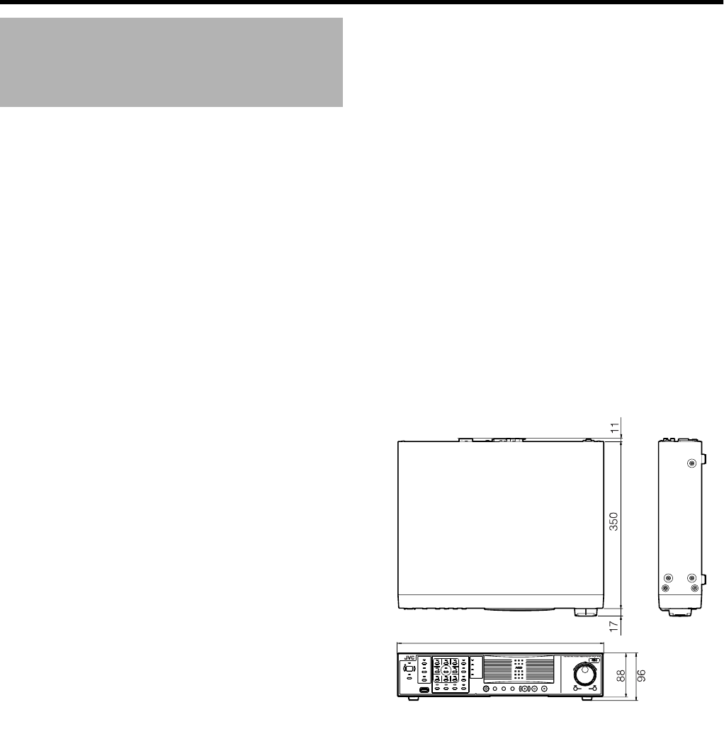
127
䡵General
Allowable Operating Temperature
: 5 I to 40 I
Allowable Storage Temperature
: -20 I to 60 I
Allowable Operating Humidity
: 30 % to 80 %
Power Supply
VR-N1600U : AC 120 V, 50 Hz/60 Hz
VR-N1600E : AC 220 V to 240 V, 50 Hz/60 Hz
Consumption Current
VR-N1600U : 1.2 A(max.)
VR-N1600E : 0.8 A(max.)
Mass : Approx. 7.6 kg
䡵Interface
Network : RJ-45⳯2
LAN1 : 1000BASE-T/100BASE-TX/10BASE-T
LAN2 : 100BASE-TX/10BASE-T
Serial : USB2.0 A-type (or equivalent) ⳯ 5
VGA Output : Max. 1600 ⳯ 1200
Audio Input : Analog audio RCA ⳯ 2 - 8 dBs 50 kK
(unbalanced)
Audio Output : Analog audio RCA ⳯ 1 - 8 dBs 600 K
(unbalanced)
I/O Terminals : Push terminal
Input ⳯ 12
Output ⳯ 5
GND ⳯ 3
䡵Compression Format
Video : JPEG/MPEG-4
Audio : μ-law (64 kbps) A/D 8 bits, Fs = 8 kHz
䡵Recording
HDD Capacity : 500 GB ⳯ 1
䡵Recording/Display/Distribution capacity
When display is available
: Max. 160 ips/80 ips/80 ips
When display is not available
: Max. 240 ips/0 ips/80 ips
(When NVR Viewer is not started up)
䡵Attachments/Accessories
VR-N1600U
Start-up Guide....................................... 1
CD-ROM................................................ 1
Power Cord (2 m) .................................. 1
Rack Mount Bracket .............................. 2
Warranty Card ....................................... 1
Service Information Card....................... 1
Screw (M4⳯10 mm).............................. 4
Screw (M5⳯11 mm).............................. 4
VR-N1600E
Start-up Guide....................................... 1
CD-ROM................................................ 1
Power Cord (2 m) .................................. 2
Rack Mount Bracket .............................. 2
Screw (M4⳯10 mm).............................. 4
Screw (M5⳯11 mm).............................. 4
䡵Dimensional Outline Drawing (Unit: mm)
TThe specifications and appearance of this unit may be
modified for improvement without prior notice.
Specifications
420
OPERATE
REC CONTROL
LIVE/BROWSE
SELECT
PTZ/PRESET
SERIAL
㧝 㧞 㧟 㧠
㧡 㧢*1/' 㧣
㧥
㧤
CANCEL ZOOM OUT ZOOM IN ENTER
WARNIN G
ALARM
HDD
LOCK
SEARCHFUNCTION ALARM CLEARKEY R EC/STOP STOP (PB) PLAY
SKIP
REV FWD
VR-N1600_J.book Page 127 Wednesday, August 8, 2007 3:32 PM

LST0603-001A© 2007 Victor Company of Japan, Limited
NETWORK VIDEO RECORDER
VR-N1600U/VR-N1600E
VR-N1600_J.book Page 128 Wednesday, August 8, 2007 3:32 PM
