JVC VR X1600U X3200U/VR User Manual X1600U, X3200U LST1260 001B
User Manual: JVC VR-X1600U VR-X1600U, VR-X3200U English,
Open the PDF directly: View PDF ![]() .
.
Page Count: 206 [warning: Documents this large are best viewed by clicking the View PDF Link!]
- Getting Started
- <Recorder Part> Basics
- <Recorder Part> Applications
- Defining a Preset PTZ Position
- Adjusting Motion Detection
- Events and Actions
- Types of Event and Action
- Events Configuration-Generic Event
- Event Configuration-Input Event
- Event Configuration-Manual Event
- Events Configuration-Timer Event
- Action Setup-Moving the PTZ Camera Preset Position
- Action Setup-Distributing Camera Images (Matrix)
- Action Setup-Starting Recording
- Action Setup-Output
- Recording Images Before/ After Occurrence of Event or Motion
- Configuring Mail Settings
- Using More Than One NVR
- Configuring Smart Client User Settings
- Configuring the Startup Password of Management Application
- Adding an HDD
- Saving/Restoring Settings
- <Recorder Part> Reference
- Setup (This Unit)
- Setting the Date and Time of This Unit
- Setting the Volume
- Setting the Password to Login to This Unit
- Management Application (Wizards)
- Management Application (Advanced Configuration)
- Changing the Monitor Settings
- Locking Operations
- Changing the System Configuration
- How to Use a Network
- Changing the Recording Settings
- Adding a Drive
- Using UPS
- Setting SNMP
- Changing the Log Storage Period
- Saving Maintenance Information
- HDD Maintenance
- <Viewer Part> Basics
- Starting Smart Client
- Viewer Description
- Installing the Viewer on a Computer
- Creating a View
- Viewing Live Images
- Manually Recording Images of a Specific Camera
- Operating Cameras on the Live Image Screen
- Viewing Recorded Images
- Searching for Recorded Images
- Search for recorded images by date and time
- Searching from the Image List
- Searching for Images by With/ Without Recording
- Searching for Recorded Images
- Searching for Recorded Images from the Alert List
- Smart Search
- Playing back Recorded Images
- Playing Back Recorded Images of Different Times for Specific Camera(s) (Independent Playback)
- Listening to recorded audio sounds
- <Viewer Part> Applications
- Printing a Recorded Image (operation from surveillance computer)
- Automatically Switching Images of Multiple Cameras
- Enlarging Images of a Selected Camera (Hotspot)
- Displaying a Web Page (HTML Page) in View
- Displaying a Still Image instead of Camera Images
- Creating a Frequently-used Operation Button
- Displaying a Floating Window
- Customizing Joystick Settings
- <Viewer Part> Reference
- Others
VR-X3200U
VR-X1600U
LST1260-001B
Powered by Milestone
NETWORK VIDEO RECORDER
INSTRUCTIONS
Please read the following before getting started:
Thank you for purchasing this JVC product.
Before operating this unit, please read the instructions
carefully to ensure the best possible performance.
For Customer Use:
Enter below the Serial No. which is located on the
body.
Retain this information for future reference.
Model No. VR-X3200U/VR-X1600U
Serial No.
IMPORTANT SAFEGUARDS
I

SAFETY PRECAUTIONS (for USA)
II
Please use this unit in an appropriate power source. Veuillez employer cette unité dans une source d'énergie
appropriée.

SAFETY PRECAUTIONS
III
Please use this unit in an appropriate power source.
IV
PRECAUTIONS WHEN MOUNTING RACK
CAUTION
● Do not install the VR-X1600U/VR-X3200U to the rack in places where ambient temperature becomes 40°C or more.
● When rack mounting, keep the internal temperature of rack assembly 40°C or less.
● When using rack mount, keep the clearance between the rack and the rear of unit 150mm or more.
● When installing this unit or the like to the rack, refer to the consumption current value of the nameplate of each
device so that the current capacity (including rated capacity of power supply wire) of the rack is not exceeded.
● Use the rack that meets the following requirements:
• must be equipped with overcurrent protection
• must be equipped with protective earthing conductor power plug and socket
CAUTION
Before you mount this device in a rack, make sure that the rack is secure and in no danger of tipping over.
To prevent bodily injury when mounting or servicing this unit in a rack, you must take special precautions to ensure that the system
remains stable.
The following guidelines are provided to ensure your safety:
This unit should be mounted at the bottom of the rack if it is the only unit in the rack.
When mounting this unit in a partially filled rack, load the rack from the bottom to the top with the heaviest component at the bottom
of the rack.
If the rack is provided with stabilizing devices, install the stabilizers before mounting or servicing the unit in the rack.

SAFETY PRECAUTIONS
V
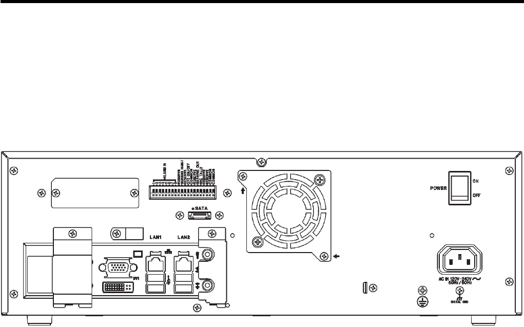
Rear view of VR-X1600U/VR-X3200U
WARNING (FOR EUROPE):
This is a Class A product. In a domestic environment this product may
cause radio interference in which case the user may be required to take
adequate measures.
INFORMATION (FOR CANADA)
RENSEIGNEMENT
(POUR CANADA)
This Class A digital apparatus complies with Canadian ICES-003.
Cet appareil num rique de la Class A est
VI
Precautions
Please note the following when using the VR-X1600U and VR-X3200U in Europe.
1. Ensure that the protective earthing terminal of the product is connected to the indoor protective grounding.
2. Please use a wire that meets the following requirements when connecting the protective earthing terminal of the product to the
indoor protective grounding.
●The color of the wire should be green with yellow stripe.
●The cross-sectional area of the conductor should be 0.8230 mm2 (18AWG or equivalent).
3. The wire connected to the protective earthing terminal must not come out easily.
4. Do not use the protective earthing terminal of the product as a signal ground terminal.
Rear view of VR-X1600U/VR-X3200U

2
Getting Started
Locations of Storage and Use
䢇Do not place this product in the following locations.
Doing so may cause this product to malfunction or break
down.
●Hot or cold places beyond the allowable operating
temperature range (5°C to 40°C)
●Humid places beyond the allowable operating humidity
range (30%RH to 80%RH)(no condensation)
●Places that emit a strong magnetic field, such as near
transformers and motors
●Places near devices that emit radio waves, such as
transceivers and mobile phones
●Places with considerable dust and sand
●Places with strong vibrations
●Places where water droplets may be formed, such as
by a window sides
●Places with considerable vapor and oil, such as
kitchens
●Places that emit radiation, X-rays, and corrosive gases
䢇Using this unit and the cable that is connected to it near
places where strong radio waves or magnetic fields are
emitted (such as near radios, TVs, transformers, and
monitors) may cause noise in the video images or color
changes.
Handling Precautions
䢇Do not stack the devices on one another during use
Heat and noise from the devices may cause the unit to
malfunction or break down, and lead to fire.
䢇Do not block the ventilation holes
Doing so may cause heat to be trapped inside the unit and
result in fire. Do not use this unit by laying it down
sideways, upside down, or at an angle.
䢇Do not place objects on this unit
Placing heavy objects, such as TV monitors, or objects
that are bigger in size on this unit may cause it to lose
balance and drop or fall, resulting in injuries.
䢇Do not stand or sit on this unit
Doing so may cause this unit to fall or break down, and
result in injuries. Keep it out of the reach of young
children.
䢇Do not place objects with water (e.g., vases, flower pots,
cups, cosmetic products, and chemicals) on this unit
Water may enter this unit through the ventilation holes and
result in fire or electric shock.
䢇Do not insert objects into this unit
Metallic or other flammable objects that enter this unit
from the ventilation holes may result in fire or electric
shock.
䢇Remove all connected cords before moving
Turn off the power and remove the power plug before
moving this unit. Failure to do so may cause damage to
the cords, and result in fire or electric shock.
Precautions for Handling Power
Cords
䢇Do not use the supplied cords on devices other than this
unit.
䢇Do not place heavy objects on the power cord, or place it
under this unit.
Doing so may cause damage to the cords, and result in
fire or electric shock.
䢇Do not use cords other than those supplied with this unit
Use only power cords supplied together with this unit.
Using cords with different withstanding voltage
specifications or damaged cords may result in fire or
electric shock.
䢇Do not remove the power plug during recording or
playback, or when the HDD is being accessed.
Maintenance
䢇Turn off the power before performing maintenance of this
unit.
䢇Wipe this unit using a soft cloth. Wiping using thinner or
benzene may cause the surface to melt or fog. When the
surface is extremely dirty, wipe using a cloth that is dipped
into a neutral detergent diluted with water, followed by
wiping with a dry cloth.
Energy Conservation
䢇Turn off the power of the system for safety reasons and to
save energy if this unit is not to be used for a long time.
Copyright
䢇Use of video or audio sound recorded using this unit for
commercial purposes or playing them for public viewing or
listening may be an infringement of the copyrights of their
respective authors under the copyright law.
䢇These video (audio) recordings shall be restricted to
personal only uses, and their use without prior consent of
the copyright holder is strictly prohibited under the
copyright law.
Precautions for Proper Use
of this Product
●All contents of this manual are the copyright of
JVC KENWOOD Corporation. No part of this manual
may be reproduced or copied without prior permission
of JVC KENWOOD Corporation.
●Names of other companies’ products referred to in this
manual are generally trademarks or registered
trademarks of the companies.In this manual, marks
such as ™, ®, and © are omitted.
●Milestone and XProtect Enterprise are registered
trademarks of Milestone Systems.

3
Precautions for Handling Hard Disk
Drive
䢇This unit comes with a high-precision hard disk device. Be
careful not to exert vibration or impact on this unit when
handling it. Exertion of vibration or impact particularly
when the power is on or when the hard disk is being
accessed may cause this unit to break down.
䢇The distance between the head and the disk is only about
0.02 μm when the hard disk (henceforth HDD) is reading
the data. Vibration or impact that is exerted on the HDD
may therefore cause the head to hit against the disk,
causing the disk surface to dent or the disk to chip. When
this occurs, data may not be properly read, or in a worse
scenario, continued use in this condition may result in
head crash (damage). Careful attention must therefore be
paid when handling it.
䢇Precautions During Installation and Change of Installation
Location
Moving of this unit or installation work is strictly prohibited
when the power of this unit is on or immediately after the
power is turned off (approximately 1 minute). The HDD
continues to move under its own inertia for some time
after the power is disconnected, and exertion of vibration
or impact during this interval may result in HDD failure.
When moving this unit, wrap it using cushioning materials
to protect it from external shock.
䢇The HDD is a consumable product. Although it may vary
according to the environment of use, it is recommended to
replace the HDD after using for 18,000 hours in a
surrounding temperature of 25°C. (However, this is only a
reference time and not a guarantee for HDD life span.)
For inquiries on maintenance plans and expenses,
consult your nearest JVC KENWOOD dealer.
䢇When installing an external hard disk, we recommend the
use of UPS (uninterruptible power supply) to ensure the
stable operation of the system.
䢇Power failure that occurs during formatting or
disconnection of the HDD may affect its subsequent use
even when the UPS is connected.
䢇JVC KENWOOD shall not be held responsible for the
compensation of losses incurred in the event that
recording or playback fails due to defects in this unit or its
hard disk drive.
䢇Images recorded on the HDD will be deleted when you
replace it with a new disk. Note also that recorded images
may be deleted when you upgrade the software for this
unit.
Software Installation
䢇Do not install any software to this device other than the
provided application software. Otherwise, operations may
become unstable. Any malfunctions which arise in such a
case will not be covered under warranty.
Anti-virus
You cannot install anti-virus software on this unit. Instead,
prepare anti-virus by Windows Firewall or the router. In
addition, do not use Windows update.
Others
䢇When there is variation in the supply voltage such as
during lightning, operation of this unit may be disabled to
protect the system until the supply voltage stabilizes
again.
䢇Eliminate static electricity before performing work that
requires you to touch the input/output terminals, such as
when installing devices.
䢇Do not touch the rear panel of this unit when it is running
as static electricity may cause it to malfunction.
䢇When there is a large amount of data recorded on this
unit, such as short alarm records, a longer time may be
required during search or backup. This is not a
malfunction.
䢇Data recorded from TV broadcasts or video (audio)
recordings shall be restricted only to personal use, and
their use without the prior consent of the copyright holder
is strictly prohibited under the copyright law.
䢇The width of the border lines (black in color) of images on
the split screen varies according to the type of input
signals. This is due to the characteristics of the camera’s
input signals, and is not a malfunction. The condition may
also be improved by adjusting this unit. For details, consult
our authorized dealers or JVC KENWOOD service
centers.
Consumable parts
The table below shows consumable parts for this unit. Repair
costs including fees for parts or replacement, or travel
expenses are charged even while this unit is under warranty.
●The maintenance cycle differs depending on the
conditions of use. The cycle above is applied when you
use this unit in 25°C environment.
●Consult our authorized dealers or JVC KENWOOD
service centers for details on the maintenance plan or
fees. (The list of JVC KENWOOD service center is
attached to this unit.)
When installed in an ordinary household, this unit may
cause interference with other devices such as radios or
televisions.
Parts Note
HDD Replace every 18,000 hours (2
years) of use.
CPU fan/Rear fan
unit
Replace every 30,000 hours (3
years) of use.
Backup battery
(CR2032)
Necessary to replace if the power is
not supplied for a long time.

4
Getting Started
Getting Started
Precautions for Proper Use of this Product ....................... 2
Locations of Storage and Use .......................................2
Handling Precautions .....................................................2
Precautions for Handling Power Cords .......................... 2
Maintenance ..................................................................2
Energy Conservation .....................................................2
Copyright ....................................................................... 2
Precautions for Handling Hard Disk Drive ..................... 3
Software Installation ...................................................... 3
Anti-virus ........................................................................ 3
Others ............................................................................3
Consumable parts .......................................................... 3
About the Software ............................................................ 6
End-User License Agreement for Milestone’s Software
embedded in JVC KENWOOD’s NVR products ............ 6
MICROSOFT SOFTWARE LICENSE TERMS ..............7
Structure of Manuals ....................................................... 17
Structure of This Manual ................................................. 17
Workflow from Installation to Operations ......................... 18
About the Software Used with This Unit .......................... 19
Overview of the Software ............................................. 19
Notices for Changing Settings .....................................19
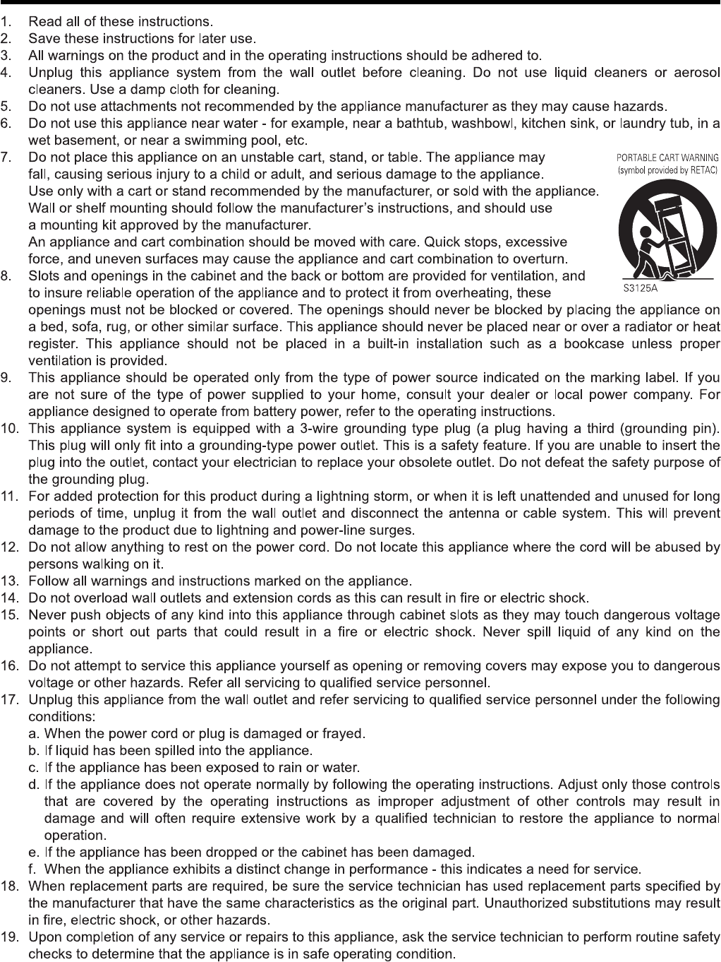
Part Names and Functions ..............................................20
Front ............................................................................. 20
Rear Panel ...................................................................21
Rear I/O Terminals .......................................................22
<Recorder Part> Basics
Mounting to a Rack ......................................................... 24
Connecting ...................................................................... 25
Basic System Configuration ......................................... 25
Devices Connected to Terminals of This Unit ..............26
Devices Connected Through a Network ...................... 28
Switching the Power On/Off ............................................29
Switching the Power On ...............................................29
Switching the Power Off ............................................... 29
Activating/Shutting Down the System ............................. 30
Activating the System ..................................................30
Shutting Down the System ..........................................30
Using the On-screen Keyboard ....................................... 30
Connect This Unit to a Network ...................................... 31
Configuring Basic Monitoring System Settings ............... 32
Starting Up Management Application ..........................32
Connecting Cameras ...................................................33
Configuring Settings of Cameras Connected ..............34
Making Full Use of Recording Performance ....................37
<Recorder Part> Applications
Defining a Preset PTZ Position .......................................39
Defining a Preset Position ............................................39
Auto PTZ Patrolling ......................................................41
Adjusting Motion Detection ..............................................44
Events and Actions ..........................................................46
Types of Event and Action ............................................46
Events Configuration—Generic Event .........................46
Event Configuration—Input Event ................................48
Event Configuration—Manual Event ............................50
Events Configuration—Timer Event .............................51
Action Setup—Moving the PTZ Camera Preset
Position ........................................................................52
Action Setup—Distributing Camera Images (Matrix) ...53
Action Setup—Starting Recording ...............................55
Action Setup—Output ..................................................56
Recording Images Before/After Occurrence of Event or
Motion ..............................................................................58
Configuring Mail Settings ................................................59
Mail Settings of Unit Setting .........................................59
Mail Setup for Management Application ......................60
Using More Than One NVR ............................................63
Specifying a Master NVR .............................................64
Registering a Slave NVR .............................................65
Configuring Smart Client User Settings ..........................66
Adding a User ..............................................................66
Limiting the Rights of Each User ..................................67
Adding a User Group ...................................................68
Configuring the Startup Password of Management
Application .......................................................................70
Adding an HDD ...............................................................71
Connecting an External HDD .......................................71
Building a RAID Configuration .....................................72
Using NAS ...................................................................75
Saving/Restoring Settings ...............................................78
Saving/Restoring the Settings of Unit Setting ..............78
Saving/Reading the Settings of Management
Application ...................................................................79
<Recorder Part> Reference
Setup (This Unit) .............................................................81
Unit Setup ....................................................................81
Network Settings ..........................................................84
Setting the Date and Time of This Unit ...........................85
Setting the Volume ..........................................................86
Setting the Password to Login to This Unit ......................87
Setting the Password ...................................................87
Validating the Password ...............................................88
Management Application (Wizards) ................................90
Management Application (Advanced Configuration) .......91
Hardware Devices ........................................................92
Cameras and Storage Information .............................100
Events and Output .....................................................105
Scheduling and Archiving ..........................................107
Matrix .........................................................................109
Logs ...........................................................................109
E-mail .........................................................................110
Server Access ............................................................111
Master/Slave ..............................................................112
Users ..........................................................................112
Contents

5
Services .....................................................................113
Changing the Monitor Settings ......................................114
Changing the Monitor Resolution ..............................114
Establishing a Dual-monitor Configuration .................115
Locking Operations ....................................................... 116
Changing the System Configuration ............................. 117
Manually Registering a Camera ................................ 117
Adding a Camera License ......................................... 118
Replacing a Hardware Device ...................................118
Deleting a Hardware Device ......................................119
How to Use a Network ..................................................119
Proper Use of LAN1/LAN2 .........................................119
Performing Remote Monitoring through WAN ............120
Changing the Recording Settings .................................121
Defining a Recording Schedule .................................121
Setting Speech Communication with Cameras ..........124
Adding a Drive ...............................................................125
Using UPS .....................................................................125
Setting SNMP ................................................................ 126
Changing the Log Storage Period ................................. 128
Changing the Log Storage Period for Management
Application .................................................................128
Changing the Log Storage Period for the Unit
Settings ......................................................................128
Saving Maintenance Information ...................................129
HDD Maintenance ......................................................... 130
Checking HDD Usage ................................................130
Checking the Load Factor of This Unit ....................... 130
Performing Error Check .............................................131
Performing Defragmentation ......................................131
Initializing the Settings ...............................................131
<Viewer Part> Basics
Starting Smart Client .....................................................133
Viewer Description ........................................................ 135
Installing the Viewer on a Computer .............................136
System Requirements ...............................................137
Computer Network Settings ....................................... 137
Installing the Smart Client .......................................... 138
Creating a View .............................................................139
Groups and Views .....................................................139
Creating a View .........................................................140
Editing Views ............................................................. 141
Viewing Live Images ..................................................... 142
Showing the Live Window ..........................................142
Switching Views ......................................................... 143
Manually Recording Images of a Specific Camera .......143
Operating Cameras on the Live Image Screen .............144
Viewing Images by Using PTZ Features .................... 144
Using the Preset Features ......................................... 144
Playing Back Recorded Images for Specific Camera(s)
(Independent Playback) .............................................145
Other Useful Features ................................................ 145
Viewing Recorded Images ............................................147
Displaying the Playback Screen .................................147
Switching Views ......................................................... 148
Searching for Recorded Images ....................................149
Search for recorded images by date and time ...........149
Searching from the Image List ...................................149
Searching for Images by With/Without Recording .....150
Searching for Recorded Images ................................151
Searching for Recorded Images from the Alert List ...151
Smart Search .............................................................152
Playing back Recorded Images .................................153
Playing Back Recorded Images of Different Times for
Specific Camera(s) (Independent Playback) ..............154
Listening to recorded audio sounds ...........................154
<Viewer Part> Applications
Printing a Recorded Image
(operation from surveillance computer) .........................156
Automatically Switching Images of Multiple Cameras ...156
Enlarging Images of a Selected Camera (Hotspot) .......157
Displaying a Web Page (HTML Page) in View ..............158
Displaying a Still Image instead of Camera Images ......159
Creating a Frequently-used Operation Button ...............160
Displaying a Floating Window .......................................160
Customizing Joystick Settings .......................................161
<Viewer Part> Reference
Saving Images and Audio Sounds on a USB Flash Memory
(Export) .........................................................................164
Saving as a Video or Still Image ................................164
Saving Images in Database Format ...........................165
Viewing Exported Data by Computer ............................167
Starting the Export Viewer .........................................167
Viewing Exported Data ..............................................167
Data Playback/Stopping Data Playback .....................168
Exiting the Export Viewer ...........................................168
Operations and Settings Available on Each Screen ......169
Live Screen ................................................................169
Playback Screen ........................................................170
Setting Screen ...........................................................171
Option Setting ................................................................176
Checking Version Information ........................................179
Setting the Matrix Display Area .....................................179
Others
Compatible Network Cameras .......................................181
Recording Time Schedule .............................................182
Default Value List ...........................................................183
Settings of This Unit ...................................................183
Settings of This Unit (Network Settings) ....................184
Management Application (Advanced Configuration) ..185
Troubleshooting .............................................................195
Recording/Displaying live images/Distribution
performance ..................................................................196
Specifications ................................................................196
Index ..............................................................................198

6
Getting Started
End-User License Agreement for
Milestone’s Software embedded in
JVC KENWOOD’s NVR products
This license agreement is a legally binding agreement among you (“You”, either an individual or a single entity),
Milestone Systems A/S (“Milestone”) and JVC KENWOOD Corporation (“JVC KENWOOD”) for the software product
embedded in JVC KENWOOD’s Network Video Recorder (“NVR”) products (“Software”), which may include associated
software components, media, printedmaterials, and online or electronic documentation, if any.
By using JVC KENWOOD's NVR product incorporating the Software, you agree to be bound by the terms of this
agreement.
The Software is protected by copyright laws and international copyright treaties, as well as other intellectual property
laws and treaties. Note that the Software is licensed, not sold.
1. Grant of Use.
Milestone hereby grants You the right to use the Software on JVC KENWOOD’s NVR products.
2. Copyright.
All title, including but not limited to copyrights, in and to the Software and any copies thereof are owned by Milestone. All rights not
expressively granted are reserved by Milestone.
3. No Warranties.
Milestone and JVC KENWOOD expressly disclaims any warranty for the Software. The Software and any related documentation
is provided Aas is” without warranty of any kind, either express or implied, including, without limitation, the implied warranties of
merchantability, fitness for a particular purpose or non-infringement. The entire risk and liability arising out of use or performance
of the Software remains with You as the user. You are notified that the Software, when used with certain equipment or other
software, may enable You to perform surveillance actions and data processing which are likely to be restricted by or contrary to
applicable law, including without limitation data privacy and criminal law. The sole responsibility for verification of Your use against
compliance with applicable law lies with you as the user.
4. Limitation of Liability.
The provisions of this paragraph are in effect to the maximum extent permitted by applicable law. In no event shall Milestone, JVC
KENWOOD or their suppliers be liable for any special, incidental, indirect, or consequential damages whatsoever (including,
without limitation, damages for loss of business profits, business interruption, loss of business information, or any other pecuniary
loss) arising out of the use of or inability to use the Software or the provision of or failure to provide proper support, even if
Milestone or JVC KENWOOD have been advised of the possibility of such damages. Absent any wilful misconduct or gross
negligence, the entire liability of Milestone and JVC KENWOOD under any provision of this agreement shall be limited to the
amount paid by you for the Software portion of JVC KENWOOD's NVR product.
5. Miscellaneous.
(a) You acknowledge that the Software is embedded in JVC KENWOOD’s NVR products, and You may not make copies of the
Software. If necessary for backup and archival purposes, please contact JVC KENWOOD.
(b) You may not remove the Software from JVC KENWOOD’s NVR product nor distribute copies of the Software to third parties.
(c) You may not reverse engineer, decompile, or disassemble any of the Software except to the extent permitted by applicable
law which cannot be contractually waived.
(d) You may permanently transfer all of Your rights for the Software, provided the recipient of JVC KENWOOD's NVR product
incorporating the Software agrees to the terms of this agreement.
6. Termination.
Without prejudice to any other rights, Milestone may terminate this license agreement if You fail to comply with its terms and
conditions. In such event you must cease to use the Software.
7. Governing Law.
These License Terms and the contract are governed by Japanese law and the sole and proper venue for the settlement of
disputes hereunder shall be the Tokyo District Court.
VR-X3200U/VR-X1600U (hereafter referred to as
“
the device
”
) contains Windows姞 Embedded Standard 7 (hereafter referred to
as
“
the software
”
), licensed from Microsot Corporation by JVC KENWOOD Corporation (JVC KENWOOD). In order to use the
device and software, you must agree to the following Microsoft Software License Terms.
About the Software

7
MICROSOFT SOFTWARE LICENSE
TERMS
WINDOWS姞 EMBEDDED STANDARD 7
These license terms are an agreement between you and JVC KENWOOD Corporation (JVC KENWOOD). Please read them. They
apply to the software included on this device. The software also includes any separate media on which you received the software.
The software on this device includes software licensed from Microsoft Corporation or its affiliate.
The terms also apply to any Microsoft
●updates,
●supplements,
●Internet-based services, and
●support services
for this software, unless other terms accompany those items. If so, those terms apply.
If you obtain updates or supplements directly from Microsoft, then Microsoft, and not JVC KENWOOD, licenses those to you.
As described below, using the software also operates as your consent to the transmission of certain computer
information for Internet-based services.
By using the software, you accept these terms. If you do not accept them, do not use the software. Instead, contact JVC
KENWOOD to determine its return policy for a refund or credit.
If you comply with these license terms, you have the rights below.
1 USE RIGHTS
Use. The software license is permanently assigned to the device with which you acquired the software. You may use the
software on the device.
2 ADDITIONAL LICENSING REQUIREMENTS AND/OR USE RIGHTS
a. Specific Use.
JVC KENWOOD designed the device for a specific use. You may only use the software for that use.
b. Other Software.
You may use other programs with the software as long as the other programs
●directly supports the manufacturer’s specific use for the device, or
●provide system utilities, resource management, or anti-virus or similar protection.
●Software that provides consumer or business tasks or processes may not be run on the device. This includes email, word
processing, spreadsheet, database, scheduling and personal finance software. The device may use terminal services
protocols to access such software running on a server.
c. Device Connections.
You may not use the software as server software. In other words, more than one device may not access, display, run, share
or use the software at the same time.
You may use terminal services protocols to connect the device to a server running business task or processes software
such as email, word processing, scheduling or spreadsheets.
You may allow up to ten other devices to access the software to use
●File Services,
●Print Services,
●Internet Information Services, and
●Internet Connection Sharing and Telephony Services.
The ten connection limit applies to devices that access the software indirectly through “multiplexing” or other software or
hardware that pools connections. You may use unlimited inbound connections at any time via TCP/IP.
d. Remote Access Technologies.
You may access and use the software remotely from another device using remote access technologies as follows.
Remote Desktop. The single primary user of the device may access a session from any other device using Remote Desktop
or similar technologies. A
“
session
”
means the experience of interacting with the software, directly or indirectly, through any
combination of input, output and display peripherals. Other users may access a session from any device using these
technologies, if the remote device is separately licensed to run the software.
Other Access Technologies. You may use Remote Assistance or similar technologies to share an active session.
Other Remote Uses. You may allow any number of devices to access the software for purposes other than those described
in the Device Connections and Remote Access Technologies sections above, such as to synchronize data between
devices.
e. Font Components.
While the software is running, you may use its fonts to display and print content. You may only
●embed fonts in content as permitted by the embedding restrictions in the fonts; and
●temporarily download them to a printer or other output device to print content.
f. Icons, images and sounds.
While the software is running, you may use but not share its icons, images, sounds, and media.

8
Getting Started
MICROSOFT SOFTWARE LICENSE
TERMS (continued)
3 VHD BOOT.
Additional copies of the software created using the software’s Virtual Hard Disk functionality (
“
VHD Image
”
) may be pre-
installed on the physical hard disk of the device. These VHD Images may only be used for maintaining or updating the software
installed on the physical hard disk or drive. If the VHD Image is the only software on your device, it may be used as the primary
operating system but all other copies of the VHD Image may only be used for maintenance and updating.
4 POTENTIALLY UNWANTED SOFTWARE.
The software may include Windows Defender. If Windows Defender is turned on, it will search this device for
“
spyware,
”
“
adware
”
and other potentially unwanted software. If it finds potentially unwanted software, the software will ask you if you want
to ignore, disable (quarantine) or remove it. Any potentially unwanted software rated
“
high
”
or
“
severe,
”
will be automatically
removed after scanning unless you change the default setting. Removing or disabling potentially unwanted software may result
in
●Other software on your device ceasing to work, or
●Your breaching a license to use other software on this device
By using this software, it is possible that you will also remove or disable software that is not potentially unwanted software.
5 SCOPE OF LICENSE.
The software is licensed, not sold. This agreement only gives you some rights to use the software. JVC KENWOOD and
Microsoft reserve all other rights. Unless applicable law gives you more rights despite this limitation, you may use the software
only as expressly permitted in this agreement. In doing so, you must comply with any technical limitations in the software that
allow you to use it only in certain ways. For more information, see the software documentation or contact JVC KENWOOD. You
may not:
●work around any technical limitations in the software;
●reverse engineer, decompile or disassemble the software;
●make more copies of the software than specified in this agreement;
●publish the software for others to copy;
●rent, lease or lend the software; or
●use the software for commercial software hosting services.
Except as expressly provided in this agreement, rights to access the software on this device do not give you any right to
implement Microsoft patents or other Microsoft intellectual property in software or devices that access this device.
6 INTERNET-BASED SERVICES.
Microsoft provides Internet-based services with the software. Microsoft may change or cancel them at any time.
a. Consent for Internet-Based Services.
The device may contain one or more of the software features described below. These features connect to Microsoft or
service provider computer systems over the Internet. In some cases, you will not receive a separate notice when they
connect. For more information about these features, visit
go.microsoft.com/fwlink/?linkid=104604.
By using these features, you consent to the transmission of this information. Microsoft does not use the information to
identify or contact you.
●Computer Information.
The following features use Internet protocols, which send to the appropriate systems computer information, such as your
Internet protocol address, the type of operating system and browser, the name and version of the software you are using,
and the language code of the device where you installed the software. Microsoft uses this information to make the
Internet-based services available to you. JVC KENWOOD has elected to turn on the following features on the device.
●Plug and Play and Plug and Play Extensions.
You may connect new hardware to your device. Your device may not have the drivers needed to communicate with that
hardware. If so, the update feature of the software can obtain the correct driver from Microsoft and install it on your device.
●Web Content Features.
Features in the software can retrieve related content from Microsoft and provide it to you. Examples of these features are
clip art, templates, online training, online assistance and Appshelp. You may choose to switch them off or not use them.
●Digital Certificates.
The software uses x.509 version 3 digital certificates. These digital certificates confirm the identity of user sending
information to each other and allow you to encrypt the information. The software retrieves certificates and updates
certificate revocation lists over the Internet.
●Auto Root Update.
The Auto Root Update feature updates the list of trusted certificate authorities. You can switch off this feature.
About the Software
(continued)

9
●Windows Media Digital Rights Management.
Content owners use Windows Media digital rights management technology (WMDRM) to protect their intellectual
property, including copyrights. This software and third party software use WMDRM to play and copy WMDRM-protected
content. If the software fails to protect the content, content owners may ask Microsoft to revoke the software’s ability to use
WMDRM to play or copy protected content. Revocation does not affect other content. When you download licenses for
protected content, you agree that Microsoft may include a revocation list with the licenses. Content owners may require
you to upgrade WMDRM to access their content. Microsoft software that includes WMDRM will ask for your consent prior
to the upgrade. If you decline an upgrade, you will not be able to access content that requires the upgrade. You may switch
off WMDRM features that access the Internet. When these features are off, you can still play content for which you have a
valid license.
●Windows Media Player.
When you use Windows Media Player, it checks with Microsoft for
●compatible online music services in your region;
●new versions of the player; and
●codecs if your device does not have the correct ones for playing content.
You can switch off this feature. For more information, go to:
go.microsoft.com/fwlink/?LinkId=51331.
●Malicious Software Removal/Clean On Upgrade.
Before installation of the software, the software will check and remove certain malicious software listed at
www.support.microsoft.com/?kbid=890830 (
“
Malware
”
) from your device. When the software checks your device for
Malware, a report will be sent to Microsoft about any Malware detected or errors that occurred while the software was
checking for Malware. No information that can be used to identify you is included in the report. You may disable the
software’s Malware reporting functionality by following the instructions found at
www.support.microsoft.com/?kbid=890830.
●Network Awareness.
This feature determines whether a system is connected to a network by either passive monitoring of network traffic or
active DNS or HTTP queries. The query only transfers standard TCP/IP or DNS information for routing purposes. You can
switch off the active query feature through a registry setting.
●Windows Time Service.
This service synchronizes with once a week to provide your l device with the correct time. The
connection uses standard NTP protocol.
●Search Suggestions Service.
In Internet Explorer, when you type a search query in the Instant Search box or type a question mark (?) before your
search term in the Address bar, you will see search suggestions as you type (if supported by your search provider).
Everything you type in the Instant Search box or in the Address bar when preceded by a question mark (?) is sent to your
search provider as you type. Also, when you press Enter or click the Search button, the text in the Instant Search box or
Address bar is sent to the search provider. If you use a Microsoft search provider, use of the information sent is subject to
the Microsoft Online Privacy Statement. This statement is available at
go.microsoft.com/fwlink/?linkid=31493. If you use a third-party search provider, use of the information sent will be subject
to the third party’s privacy practices. You can turn search suggestions off at any time. To do so, use Manage Add-ons
under the Tools button in Internet Explorer. For more information about the search suggestions service, see
go.microsoft.com/fwlink/?linkid=128106.
●Consent to Update Infrared Emitter/Receiver.
The software may contain technology to ensure the proper functioning of the infrared emitter/receiver device shipped with
certain Media Center-based products. You agree that the software may update the firmware of this device.
●Media Center Online Promotions.
If you use Media Center features of the software to access Internet-based content or other Internet-based services, such
services may obtain the following information from the software to enable you to receive, accept and use certain
promotional offers:
●certain device information, such as your Internet protocol address, the type of operating system and browser you are
using, and the name and version of the software you are using,
●the requested content, and
●the language code of the device where you installed the software.
●Your use of the Media Center features to connect to those services serves as your consent to the collection and use of
such information.
●Media Playback Updates.
The software on the device may include media playback features which receives updates directly from the MSCORP
Media Playback Update servers. If activated by your manufacturer, these updates will be downloaded and installed
without further notice to you. The manufacturer is responsible for ensuring these updates work on your device.

10
Getting Started
MICROSOFT SOFTWARE LICENSE
TERMS (continued)
●Windows Update Agent.
The software on the device includes Windows Update Agent (“WUA”). This feature enables your device to access Windows
Updates either directly from MSCORP Windows Update server or from a server installed with the required server component
and from the Microsoft Windows Update server. To enable the proper functioning of the Windows Update service in the
software (if you use it) updates or downloads to the Windows Update service will be required from time to time and
downloaded and installed without further notice to you. Without limiting any other disclaimer in these license terms or any
license terms accompanying a Windows Update, you acknowledge and agree that no warranty is provided by Microsoft
Corporation or their affiliates with respect to any Windows Update that you install or attempt to install on your device.
b. Use of Information.
Microsoft may use the device information, error reports, and Malware reports to improve our software and services. We may
also share it with others, such as hardware and software vendors. They may use the information to improve how their
products run with Microsoft software.
c. Misuse of Internet-based Services.
You may not use these services in any way that could harm them or impair anyone else’s use of them. You may not use the
services to try to gain unauthorized access to any service, data, account or network by any means.
7 PRODUCT SUPPORT.
Contact JVC KENWOOD for support options.
Refer to the support number provided with the device.
8 MICROSOFT .NET BENCHMARK TESTING.
The software includes one or more components of the .NET Framework (
“
.NET Components
”
). You may conduct internal
benchmark testing of those components. You may disclose the results of any benchmark test of those components, provided
that you comply with the conditions set forth at go.microsoft.com/fwlink/?LinkID=66406.
Notwithstanding any other agreement you may have with Microsoft, if you disclose such benchmark test results, Microsoft shall
have the right to disclose the results of benchmark tests it conducts of your products that compete with the applicable .NET
Component, provided it complies with the same conditions set forth at go.microsoft.com/fwlink/?LinkID=66406.
9 BACKUP COPY.
You may make one backup copy of the software. You may use it only to reinstall the software on the device.
10 DOCUMENTATION.
Any person that has valid access to your device or internal network may copy and use the documentation for your internal,
reference purposes.
11 PROOF OF LICENSE.
If you acquired the software on the device, or on a disc or other media, a genuine Certificate of Authenticity label with a
genuine copy of the software identifies licensed software. To be valid, this label must be affixed to the device, or included on
or in JVC KENWOOD’s software packaging. If you receive the label separately, it is not valid. You should keep the label on
the device or packaging to prove that you are licensed to use the software. To identify genuine Microsoft software, see
www.howtotell.com.
12 TRANSFER TO A THIRD PARTY.
You may transfer the software only with the device, the Certificate of Authenticity label, and these license terms directly to a
third party. Before the transfer, that party must agree that these license terms apply to the transfer and use of the software.
You may not retain any copies of the software including the backup copy.
13 NOTICE ABOUT THE H.264/AVC VISUAL STANDARD, THE VC-1 VIDEO STANDARD, THE MPEG-4
VISUAL STANDARD AND THE MPEG-2 VIDEO STANDARD.
This software may include H.264/AVC, VC-1, MPEG-4 Part 2, and MPEG-2 visual compression technology. If the software
includes those visual compression technologies MPEG LA, L.L.C. requires this notice:
THIS PRODUCT IS LICENSED UNDER ONE OR MORE VIDEO PATENT PORTFOLIO LICENSES SUCH AS, AND
WITHOUT LIMITATION, THE AVC, THE VC-1, THE MPEG-4 PART 2 VISUAL, AND THE MPEG-2 VIDEO PATENT
PORTFOLIO LICENSES FOR THE PERSONAL AND NON-COMMERCIAL USE OF A CONSUMER TO (i) ENCODE
VIDEO IN COMPLIANCE WITH THE ABOVE STANDARDS (
“
VIDEO STANDARDS
”
) AND/OR (ii) DECODE VIDEO THAT
WAS ENCODED BY A CONSUMER ENGAGED IN A PERSONAL AND NON-COMMERCIAL ACTIVITY OR WAS
OBTAINED FROM A VIDEO PROVIDER LICENSED TO PROVIDE VIDEO UNDER SUCH PATENT PORTFOLIO
LICENSES. NONE OF THE LICENSES EXTEND TO ANY OTHER PRODUCT REGARDLESS OF WHETHER SUCH
PRODUCT IS INCLUDED WITH THIS PRODUCT IN A SINGLE ARTICLE. NO LICENSE IS GRANTED OR SHALL BE
IMPLIED FOR ANY OTHER USE. ADDITIONAL INFORMATION MAY BE OBTAINED FROM MPEG LA, L.L.C. SEE
WWW.MPEGLA.COM.
About the Software
(continued)

11
14 NOTICE ABOUT THE MP3 AUDIO STANDARD.
This software includes MP3 audio encoding and decoding technology as defined by ISO/IEC 11172-3 and ISO/IEC 13818-
3. It is not licensed for any implementation or distribution in any commercial product or service.
15 NOT FAULT TOLERANT.
The software is not fault tolerant. JVC KENWOOD installed the software on the device and is responsible for how it operates
on the device.
16 RESTRICTED USE.
The Microsoft software was designed for systems that do not require fail-safe performance. You may not use the Microsoft
software in any device or system in which a malfunction of the software would result in foreseeable risk of injury or death to
any person. This includes operation of nuclear facilities, aircraft navigation or communication systems and air traffic control.
17 NO WARRANTIES FOR THE SOFTWARE.
The software is provided
“
as is
”
. You bear all risks of using it. Microsoft gives no express warranties, guarantees or
conditions. Any warranties you receive regarding the device or the software do not originate from, and are not binding on,
Microsoft or its affiliates. When allowed by your local laws, JVC KENWOOD and Microsoft exclude implied warranties of
merchantability, fitness for a particular purpose and non-infringement.
18 LIABILITY LIMITATIONS.
You can recover from Microsoft and its affiliates only direct damages up to two hundred fifty U.S. Dollars (U.S. $250.00). You
cannot recover any other damages, including consequential, lost profits, special, indirect or incidental damages.
This limitation applies to:
●anything related to the software, services, content (including code) on third party internet sites, or third party programs,
and
●claims for breach of contract, breach of warranty, guarantee or condition, strict liability, negligence, or other tort to the
extent permitted by applicable law.
It also applies even if Microsoft should have been aware of the possibility of the damages. The above limitation may not
apply to you because your country may not allow the exclusion or limitation of incidental, consequential or other damages.
19 EXPORT RESTRICTIONS.
The software is subject to United States export laws and regulations. You must comply with all domestic and international
export laws and regulations that apply to the software. These laws include restrictions on destinations, end users and end
use. For additional information, see www.microsoft.com/exporting.
20 ENTIRE AGREEMENT.
This agreement, additional terms (including any printed-paper license terms that accompany the software and may modify
or replace some or all of these terms), and the terms for supplements, updates, Internet-based services and support
services that you use, are the entire agreement for the software and support services.
21 APPLICABLE LAW
a. United States.
If you acquired the software in the United States, Washington state law governs the interpretation of this agreement and
applies to claims for breach of it, regardless of conflict of laws principles. The laws of the state where you live govern all
other claims, including claims under state consumer protection laws, unfair competition laws, and in tort.
b. Outside the United States.
If you acquired the software in any other country, the laws of that country apply.
22 Third Party Programs.
Microsoft provides the following copyright notices for third party software included in the software. These notices are
required by the respective copyright holders and do not change your license to use this software.
Note:
●The support number refers to the serial number of this unit.

12
Getting Started
MICROSOFT SOFTWARE LICENSE
TERMS (continued)
●Portions of this software are based in part on the work of
Spider Systems ® Limited. Because Microsoft has
included the Spider Systems Limited software in this
product, Microsoft is required to include the following text
that accompanied such software:
Copyright 1987 Spider Systems Limited
Copyright 1988 Spider Systems Limited
Copyright 1990 Spider Systems Limited
●Portions of this software are based in part on the work of
Seagate Software.
●Portions of this software are based in part on the work of
ACE*COMM Corp. Because Microsoft has included the
ACE*COMM Corp. software in this product, Microsoft is
required to include the following text that accompanied
such software:
Copyright 1995-1997 ACE*COMM Corp
●Portions of this software are based in part on the work of
Sam Leffler and Silicon Graphics, Inc. Because Microsoft
has included the Sam Leffler and Silicon Graphics
software in this product, Microsoft is required to include
the following text that accompanied such software:
Copyright © 1988-1997 Sam Leffler
Copyright © 1991-1997 Silicon Graphics, Inc.
Permission to use, copy, modify, distribute, and sell
this software and its documentation for any purpose is
hereby granted without fee, provided that (i) the above
copyright notices and this permission notice appear in
all copies of the software and related documentation,
and (ii) the names of Sam Leffler and Silicon Graphics
may not be used in any advertising or publicity relating
to the software without the specific, prior written
permission of Sam Leffler and Silicon Graphics.
THE SOFTWARE IS PROVIDED
“
AS-IS
”
AND
WITHOUT WARRANTY OF ANY KIND, EXPRESS,
IMPLIED OR OTHERWISE, INCLUDING WITHOUT
LIMITATION, ANY WARRANTY OF
MERCHANTABILITY OR FITNESS FOR A
PARTICULAR PURPOSE.
IN NO EVENT SHALL SAM LEFFLER OR SILICON
GRAPHICS BE LIABLE FOR ANY SPECIAL,
INCIDENTAL, INDIRECT OR CONSEQUENTIAL
DAMAGES OF ANY KIND, OR ANY DAMAGES
WHATSOEVER RESULTING FROM LOSS OF USE,
DATA OR PROFITS, WHETHER OR NOT ADVISED
OF THE POSSIBILITY OF DAMAGE, AND ON ANY
THEORY OF LIABILITY, ARISING OUT OF OR IN
CONNECTION WITH THE USE OR PERFORMANCE
OF THIS SOFTWARE.
Portions Copyright © 1998 PictureTel Corporation
●Portions of this software are based in part on the work of
Highground Systems. Because Microsoft has included the
Highground Systems software in this product, Microsoft is
required to include the following text that accompanied
such software:
Copyright © 1996-1999 Highground Systems
●Windows 7 incorporates compression code from the Info-
ZIP group. There are no extra charges or costs due to the
use of this code, and the original compression sources
are freely available from www.info-zip.org/ or ftp://ftp.info-
zip.org/pub/infozip/src/ on the Internet.
Portions Copyright © 2000 SRS Labs, Inc
●This product includes software from the 'zlib' general
purpose compression library.
●Portions of this software are based in part on the work of
ScanSoft, Inc. Because Microsoft has included the
ScanSoft, Inc. software in this product, Microsoft is
required to include the following text that accompanied
such software:
TextBridge® OCR © by ScanSoft, Inc.
●Portions of this software are based in part on the work of
University of Southern California. Because Microsoft has
included the University of Southern California software in
this product, Microsoft is required to include the following
text that accompanied such software:
Copyright © 1996 by the University of Southern
California
All rights reserved.
Permission to use, copy, modify, and distribute this
software and its documentation in source and binary
forms for any purpose and without fee is hereby
granted, provided that both the above copyright notice
and this permission notice appear in all copies, and
that any documentation, advertising materials, and
other materials related to such distribution and use
acknowledge that the software was developed in part
by the University of Southern California, Information
Sciences Institute. The name of the University may not
be used to endorse or promote products derived from
this software without specific prior written permission.
THE UNIVERSITY OF SOUTHERN CALIFORNIA
makes no representations about the suitability of this
software for any purpose. THIS SOFTWARE IS
PROVIDED
“
AS IS
”
AND WITHOUT ANY EXPRESS
OR IMPLIED WARRANTIES, INCLUDING, WITHOUT
LIMITATION, THE IMPLIED WARRANTIES OF
MERCHANTABILITY AND FITNESS FOR A
PARTICULAR PURPOSE.
Other copyrights might apply to parts of this software
and are so noted when applicable.
●Portions of this software are based in part on the work of
James Kanze. Because Microsoft has included the James
Kanze software in this product, Microsoft is required to
include the following text that accompanied such software:
COPYRIGHT AND PERMISSION NOTICE
All rights reserved.
Permission is hereby granted, free of charge, to any
person obtaining a copy of this software and
associated documentation files (the “Software
”
), to
deal in the Software without restriction, including
without limitation the rights to use, copy, publish,
distribute, and/or sell copies of the Software, and to
permit persons to whom the Software is furnished to
do so, provided that the above copyright notice(s) and
this permission notice appear in all copies of the
About the Software
(continued)

13
Software and that both the above copyright notice(s)
and this permission notice appear in supporting
documentation. Permission is also given to modify the
software to any extend, under the condition that, in the
modified software, the prefix “GB_
”
is changed to
something else, and the name directories for includes
files (“gb
”
in this distribution) is also changed.
THE SOFTWARE IS PROVIDED “AS IS
”
, WITHOUT
WARRANTY OF ANY KIND, EXPRESS OR IMPLIED,
INCLUDING BUT NOT LIMITED TO THE
WARRANTIES OF MERCHANTABILITY, FITNESS
FOR A PARTICULAR PURPOSE AND
NONINFRINGEMENT OF THIRD PARTY RIGHTS. IN
NO EVENT SHALL THE COPYRIGHT HOLDER OR
HOLDERS INCLUDED IN THIS NOTICE BE LIABLE
FOR ANY CLAIM, OR ANY SPECIAL INDIRECT OR
CONSEQUENTIAL DAMAGES, OR ANY DAMAGES
WHATSOEVER RESULTING FROM LOSS OF USE,
DATA OR PROFITS, WHETHER IN AN ACTION OF
CONTRACT, NEGLIGENCE OR OTHER TORTIOUS
ACTION, ARISING OUT OF OR IN CONNECTION
WITH THE USE OR PERFORMANCE OF THIS
SOFTWARE.
Except as contained in this notice, the name of a
copyright holder shall not be used in advertising or
otherwise to promote the sale, use or other dealings in
this Software without prior written authorization of the
copyright holder.
●This product contains software from Cisco ISAKMP
Services.
●Portions of this software are based in part on the work of
RSA Data Security, Inc. Because Microsoft has included
the RSA Data Security, Inc. software in this product,
Microsoft is required to include the following text that
accompanied such software:
Copyright © 1990, RSA Data Security, Inc. All rights
reserved.
License to copy and use this software is granted
provided that it is identified as the “RSA Data Security,
Inc. MD5 Message-Digest Algorithm
”
in all material
mentioning or referencing this software or this
function. License is also granted to make and use
derivative works provided that such works are
identified as “derived from the RSA Data Security, Inc.
MD5 Message-Digest Algorithm
”
in all material
mentioning or referencing the derived work.
RSA Data Security, Inc. makes no representations
concerning either the merchantability of this software
or the suitability of this software for any particular
purpose. It is provided “as is
”
without express or
implied warranty of any kind.
These notices must be retained in any copies of any
part of this documentation and/or software.
●Portions of this software are based in part on the work of
OpenVision Technologies, Inc. Because Microsoft has
included the OpenVision Technologies, Inc. software in
this product, Microsoft is required to include the following
text that accompanied such software:
Copyright 1993 by OpenVision Technologies, Inc.
Permission to use, copy, modify, distribute, and sell
this software and its documentation for any purpose is
hereby granted without fee, provided that the above
copyright notice appears in all copies and that both
that copyright notice and this permission notice
appear in supporting documentation, and that the
name of OpenVision not be used in advertising or
publicity pertaining to distribution of the software
without specific, written prior permission. OpenVision
makes no representations about the suitability of this
software for any purpose. It is provided “as is
”
without
express or implied warranty.
OPENVISION DISCLAIMS ALL WARRANTIES WITH
REGARD TO THIS SOFTWARE, INCLUDING ALL
IMPLIED WARRANTIES OF MERCHANTABILITY
AND FITNESS, IN NO EVENT SHALL OPENVISION
BE LIABLE FOR ANY SPECIAL, INDIRECT OR
CONSEQUENTIAL DAMAGES OR ANY DAMAGES
WHATSOEVER RESULTING FROM LOSS OF USE,
DATA OR PROFITS, WHETHER IN AN ACTION OF
CONTRACT, NEGLIGENCE OR OTHER TORTIOUS
ACTION, ARISING OUT OF OR IN CONNECTION
WITH THE USE OR PERFORMANCE OF THIS
SOFTWARE.
●Portions of this software are based in part on the work of
Regents of The University of Michigan. Because Microsoft
has included the Regents of The University of Michigan
software in this product, Microsoft is required to include
the following text that accompanied such software:
Copyright © 1995, 1996 Regents of The University of
Michigan.
All Rights Reserved.
Permission to use, copy, modify, and distribute this
software and its documentation for any purpose and
without fee is hereby granted, provided that the above
copyright notice appears in all copies and that both
that copyright notice and this permission notice
appear in supporting documentation, and that the
name of The University of Michigan not be used in
advertising or publicity pertaining to distribution of the
software without specific, written prior permission.
This software is supplied as is without expressed or
implied warranties of any kind.
Copyright © 1993, 1994 Regents of the University of
Michigan.
All rights reserved.
Redistribution and use in source and binary forms are
permitted provided that this notice is preserved and
that due credit is given to the University of Michigan at
Ann Arbor. The name of the University may not be
used to endorse or promote products derived from this
software without specific prior written permission. This
software is provided “as is
”
without express or implied
warranty.

14
Getting Started
MICROSOFT SOFTWARE LICENSE
TERMS (continued)
●Portions of this software are based in part on the work of
Massachusetts Institute of Technology. Because Microsoft
has included the Massachusetts Institute of Technology
software in this product, Microsoft is required to include
the following text that accompanied such software:
Copyright 1989, 1990 by the Massachusetts Institute
of Technology. All Rights Reserved.
Export of this software from the United States of
America may require a specific license from the United
States Government. It is the responsibility of any
person or organization contemplating export to obtain
such a license before exporting.
WITHIN THAT CONSTRAINT, permission to use,
copy, modify, and distribute this software and its
documentation for any purpose and without fee is
hereby granted, provided that the above copyright
notice appear in all copies and that both that copyright
notice and this permission notice appear in supporting
documentation, and that the name of M.I.T. not be
used in advertising or publicity pertaining to
distribution of the software without specific, written
prior permission. M.I.T. makes no representations
about the suitability of this software for any purpose. It
is provided “as is
”
without express or implied warranty.
Under U.S. law, this software may not be exported
outside the US without license from the U.S.
Commerce department.
Copyright 1994 by the Massachusetts Institute of
Technology. All Rights Reserved.
Export of this software from the United States of
America may require a specific license from the United
States Government. It is the responsibility of any
person or organization contemplating export to obtain
such a license before exporting.
WITHIN THAT CONSTRAINT, permission to use,
copy, modify, and distribute this software and its
documentation for any purpose and without fee is
hereby granted, provided that the above copyright
notice appear in all copies and that both that copyright
notice and this permission notice appear in supporting
documentation, and that the name of M.I.T. not be
used in advertising or publicity pertaining to
distribution of the software without specific, written
prior permission. M.I.T. makes no representations
about the suitability of this software for any purpose. It
is provided “as is
”
without express or implied warranty.
●This product includes software developed by the
University of California, Berkeley and its contributors.
●Portions of this software are based in part on the work of
the “Entrust
”
security technology licensed from Northern
Te l e c o m .
●Portions of this software are based in part on the work of
Hewlett-Packard Company. Because Microsoft has
included the Hewlett-Packard Company software in this
product, Microsoft is required to include the following text
that accompanied such software:
Copyright © 1994 Hewlett-Packard Company
Permission to use, copy, modify, distribute and sell this
software and its documentation for any purpose is
hereby granted without fee, provided that the above
copyright notice appear in all copies and that both that
copyright notice and this permission notice appear in
supporting documentation. Hewlett-Packard Company
and Microsoft Corporation make no representations
about the suitability of this software for any purpose. It
is provided “as is
”
without express or implied warranty.
●This product includes software from the 'libpng' PNG
reference library.
●Portions of this software are based in part on the work of
Autodesk, Inc. Because Microsoft has included the
Autodesk, Inc. software in this product, Microsoft is
required to include the following text that accompanied
such software:
© Copyright 1995 by Autodesk, Inc.
●This product contains graphics filter software; this
software is based in part on the work of the Independent
JPEG Group.
●This product includes “True Verb” technology from KS
Waves Ltd.
●Portions of this software are based in part on the work of
SGS-Thomson Microelectronics, Inc. Because Microsoft
has included the SGS-Thomson Microelectronics, Inc.
software in this product, Microsoft is required to include
the following text that accompanied such software:
Copyright 1996 SGS-Thomson Microelectronics, Inc.
All Rights Reserved
●Portions of this software are based in part on the work of
Unicode, Inc. Because Microsoft has included the
Unicode, Inc. software in this product, Microsoft is
required to include the following text that accompanied
such software:
COPYRIGHT AND PERMISSION NOTICE
Copyright © 1991-2005 Unicode, Inc. All rights
reserved. Distributed under the Terms of Use in
www.unicode.org/copyright.html.
Permission is hereby granted, free of charge, to any
person obtaining a copy of the Unicode data files and
any associated documentation (the “Data Files”) or
Unicode software and any associated documentation
(the “Software”) to deal in the Data Files or Software
without restriction, including without limitation the
rights to use, copy, modify, merge, publish, distribute,
and/or sell copies of the Data Files or Software, and to
permit persons to whom the Data Files or Software
are furnished to do so, provided that (a) the above
copyright notice(s) and this permission notice appear
with all copies of the Data Files or Software, (b) both
the above copyright notice(s) and this permission
notice appear in associated documentation, and ©
there is clear notice in each modified Data File or in
the Software as well as in the documentation
associated with the Data File(s) or Software that the
data or software has been modified.
THE DATA FILES AND SOFTWARE ARE PROVIDED
“AS IS”, WITHOUT WARRANTY OF ANY KIND,
EXPRESS OR IMPLIED, INCLUDING BUT NOT
LIMITED TO THE WARRANTIES OF
MERCHANTABILITY, FITNESS FOR A PARTICULAR
PURPOSE AND NONINFRINGEMENT OF THIRD
PARTY RIGHTS. IN NO EVENT SHALL THE
COPYRIGHT HOLDER OR HOLDERS INCLUDED IN
THIS NOTICE BE LIABLE FOR ANY CLAIM, OR ANY
SPECIAL INDIRECT OR CONSEQUENTIAL
About the Software
(continued)

15
DAMAGES, OR ANY DAMAGES WHATSOEVER
RESULTING FROM LOSS OF USE, DATA OR
PROFITS, WHETHER IN AN ACTION OF
CONTRACT, NEGLIGENCE OR OTHER TORTIOUS
ACTION, ARISING OUT OF OR IN CONNECTION
WITH THE USE OR PERFORMANCE OF THE DATA
FILES OR SOFTWARE.
Except as contained in this notice, the name of a
copyright holder shall not be used in advertising or
otherwise to promote the sale, use or other dealings in
these Data Files or Software without prior written
authorization of the copyright holder.
●The Combined PostScript Driver was the result of a
cooperative development process by Adobe Systems
Incorporated and Microsoft Corporation.
●Portions of this software are based in part on the work of
Media Cybernetics. Because Microsoft has included the
Media Cybernetics software in this product, Microsoft is
required to include the following text that accompanied
such software:
HALO Image File Format Library © 1991-1992 Media
Cybernetics, Inc.
●Portions of this software are based in part on the work of
Luigi Rizzo. Because Microsoft has included the Luigi
Rizzo software in this product, Microsoft is required to
include the following text that accompanied such software:
© 1997-98 Luigi Rizzo (luigi@iet.unipi.it)
Portions derived from code by Phil Karn
(karn@ka9q.ampr.org), Robert Morelos-Zaragoza
(robert@spectra.eng.hawaii.edu) and Hari
Thirumoorthy (harit@spectra.eng.hawaii.edu), Aug
1995
Redistribution and use in source and binary forms,
with or without modification, are permitted provided
that the following conditions are met:
1. Redistributions of source code must retain the
above copyright notice, this list of conditions and the
following disclaimer.
2. Redistributions in binary form must reproduce the
above copyright notice, this list of conditions and the
following disclaimer in the documentation and/or other
materials provided with the distribution.
THIS SOFTWARE IS PROVIDED BY THE AUTHORS
“AS IS” AND ANY EXPRESS OR IMPLIED
WARRANTIES, INCLUDING, BUT NOT LIMITED TO,
THE IMPLIED WARRANTIES OF
MERCHANTABILITY AND FITNESS FOR A
PARTICULAR PURPOSE ARE DISCLAIMED. IN NO
EVENT SHALL THE AUTHORS BE LIABLE FOR
ANY DIRECT, INDIRECT, INCIDENTAL, SPECIAL,
EXEMPLARY, OR CONSEQUENTIAL DAMAGES
(INCLUDING, BUT NOT LIMITED TO,
PROCUREMENT OF SUBSTITUTE GOODS OR
SERVICES; LOSS OF USE, DATA, OR PROFITS; OR
BUSINESS INTERRUPTION) HOWEVER CAUSED
AND ON ANY THEORY OF LIABILITY, WHETHER IN
CONTRACT, STRICT LIABILITY, OR TORT
(INCLUDING NEGLIGENCE OR OTHERWISE)
ARISING IN ANY WAY OUT OF THE USE OF THIS
SOFTWARE, EVEN IF ADVISED OF THE
POSSIBILITY OF SUCH DAMAGE.
●Portions of this software are based in part on the work of
W3C. Because Microsoft has included the W3C software
in this product, Microsoft is required to include the
following text that accompanied such software:
W3C ® SOFTWARE NOTICE AND LICENSE
www.w3.org/Consortium/Legal/2002/copyright-
software-20021231
This work (and included software, documentation such
as READMEs, or other related items) is being
provided by the copyright holders under the following
license. By obtaining, using and/or copying this work,
you (the licensee) agree that you have read,
understood, and will comply with the following terms
and conditions.
Permission to copy, modify, and distribute this software
and its documentation, with or without modification, for
any purpose and without fee or royalty is hereby
granted, provided that you include the following on
ALL copies of the software and documentation or
portions thereof, including modifications:
1. The full text of this NOTICE in a location viewable to
users of the redistributed or derivative work.
2. Any pre-existing intellectual property disclaimers,
notices, or terms and conditions. If none exist, the
W3C Software Short Notice should be included
(hypertext is preferred, text is permitted) within the
body of any redistributed or derivative code.
3. Notice of any changes or modifications to the files,
including the date changes were made. (We
recommend you provide URLs to the location from
which the code is derived.)
THIS SOFTWARE AND DOCUMENTATION IS
PROVIDED “AS IS,” AND COPYRIGHT HOLDERS
MAKE NO REPRESENTATIONS OR WARRANTIES,
EXPRESS OR IMPLIED, INCLUDING BUT NOT
LIMITED TO, WARRANTIES OF MERCHANTABILITY
OR FITNESS FOR ANY PARTICULAR PURPOSE OR
THAT THE USE OF THE SOFTWARE OR
DOCUMENTATION WILL NOT INFRINGE ANY
THIRD PARTY PATENTS, COPYRIGHTS,
TRADEMARKS OR OTHER RIGHTS.
COPYRIGHT HOLDERS WILL NOT BE LIABLE FOR
ANY DIRECT, INDIRECT, SPECIAL OR
CONSEQUENTIAL DAMAGES ARISING OUT OF
ANY USE OF THE SOFTWARE OR
DOCUMENTATION.
The name and trademarks of copyright holders may
NOT be used in advertising or publicity pertaining to
the software without specific, written prior permission.
Title to copyright in this software and any associated
documentation will at all times remain with copyright
holders.

16
Getting Started
MICROSOFT SOFTWARE LICENSE
TERMS (continued)
●Portions of this software are based in part on the work of
Sun Microsystems, Inc. Because Microsoft has included
the Sun Microsystems, Inc. software in this product,
Microsoft is required to include the following text that
accompanied such software:
Sun RPC is a product of Sun Microsystems, Inc. and
is provided for unrestricted use provided that this
legend is included on all tape media and as a part of
the software program in whole or part. Users may
copy or modify Sun RPC without charge, but are not
authorized to license or distribute it to anyone else
except as part of a product or program developed by
the user.
SUN RPC IS PROVIDED AS IS WITH NO
WARRANTIES OF ANY KIND INCLUDING THE
WARRANTIES OF DESIGN, MERCHANTIBILITY
AND FITNESS FOR A PARTICULAR PURPOSE, OR
ARISING FROM A COURSE OF DEALING, USAGE
OR TRADE PRACTICE.
Sun RPC is provided with no support and without any
obligation on the part of Sun Microsystems, Inc. to
assist in its use, correction, modification or
enhancement.
SUN MICROSYSTEMS, INC. SHALL HAVE NO
LIABILITY WITH RESPECT TO THE
INFRINGEMENT OF COPYRIGHTS, TRADE
SECRETS OR ANY PATENTS BY SUN RPC OR ANY
PART THEREOF.
In no event will Sun Microsystems, Inc. be liable for
any lost revenue or profits or other special, indirect
and consequential damages, even if Sun has been
advised of the possibility of such damages.
Sun Microsystems, Inc.
2550 Garcia Avenue
Mountain View, California 94043
●Manufactured under license from Dolby Laboratories.
“Dolby” and the double-D symbol are trademarks of Dolby
Laboratories. Confidential unpublished works. Copyright
1992-1997 Dolby Laboratories. All rights reserved.
●Portions of this software are based in part on the work of
Andrei Alexandrescu. Because Microsoft has included the
Andrei Alexandrescu software in this product, Microsoft is
required to include the following text that accompanied
such software:
The Loki Library
Copyright © 2001 by Andrei Alexandrescu
This code accompanies the book:
Alexandrescu, Andrei. “Modern C++ Design: Generic
Programming and Design Patterns Applied.” Copyright
© 2001. Addison-Wesley.
Permission to use, copy, modify, distribute and sell this
software for any purpose is hereby granted without
fee, provided that the above copyright notice appear in
all copies and that both that copyright notice and this
permission notice appear in supporting
documentation.
The author or Addison-Welsey Longman make no
representations about the suitability of this software for
any purpose. It is provided “as is” without express or
implied warranty.
Portions Copyright © 1995 by Jeffrey Richter
●Portions of this software are based in part on the work of
the Distributed Management Task Force, Inc. (DMTF).
Because Microsoft has included software based on DMTF
specifications in this product, Microsoft is required to
include the following text:
Copyright © 2007 Distributed Management Task
Force, Inc. (DMTF). All rights reserved.
●Portions of this work are derived from “The Draft Standard
C++ Library” Copyright © 1995 by P.J. Plauger published
by Prentice-Hall and are used with permission.
●Portions of this software are based in part on the work of
Hewlett-Packard Company. Because Microsoft has
included the Hewlett-Packard Company software in this
product, Microsoft is required to include the following text
that accompanied such software:
Copyright © 2002, 2003 Hewlett-Packard Company.
About Notice:
This software is based on software available from
mpvtools.sourceforge.net.
This software processes a format called MPV. MPV is
an open specification for managing collections and
multimedia playlists of photo, video, and music content
and associated metadata and is available at no cost
from the Optical Storage Technology Association.
More information about the MPV specification can be
found at www.osta.org/mpv.
Permission Notice:
Permission is hereby granted, free of charge, to any
person obtaining a copy of this software and
associated documentation files (the “Software”), to
deal in the Software without restriction, including
without limitation the rights to use, copy, modify,
merge, publish, distribute, sublicense, and/or sell
copies of the Software, and to permit persons to whom
the Software is furnished to do so, subject to the
following conditions:
The above copyright notice, this permission notice,
and the above About Notice shall be included in all
copies or substantial portions of the Software.
THE SOFTWARE IS PROVIDED “AS IS”, WITHOUT
WARRANTY OF ANY KIND, EXPRESS OR IMPLIED,
INCLUDING BUT NOT LIMITED TO THE
WARRANTIES OF MERCHANTABILITY, FITNESS
FOR A PARTICULAR PURPOSE AND
NONINFRINGEMENT. IN NO EVENT SHALL THE
AUTHORS OR COPYRIGHT HOLDERS BE LIABLE
FOR ANY CLAIM, DAMAGES OR OTHER LIABILITY,
WHETHER IN AN ACTION OF CONTRACT, TORT
OR OTHERWISE, ARISING FROM, OUT OF OR IN
CONNECTION WITH THE SOFTWARE OR THE USE
OR OTHER DEALINGS IN THE SOFTWARE.
Except as contained in this notice, the name of a
copyright holder shall not be used in advertising or
otherwise to promote the sale, use or other dealings in
this Software without prior written authorization of the
copyright holder.
All other trademarks are property of their respective owners.
About the Software
(continued)
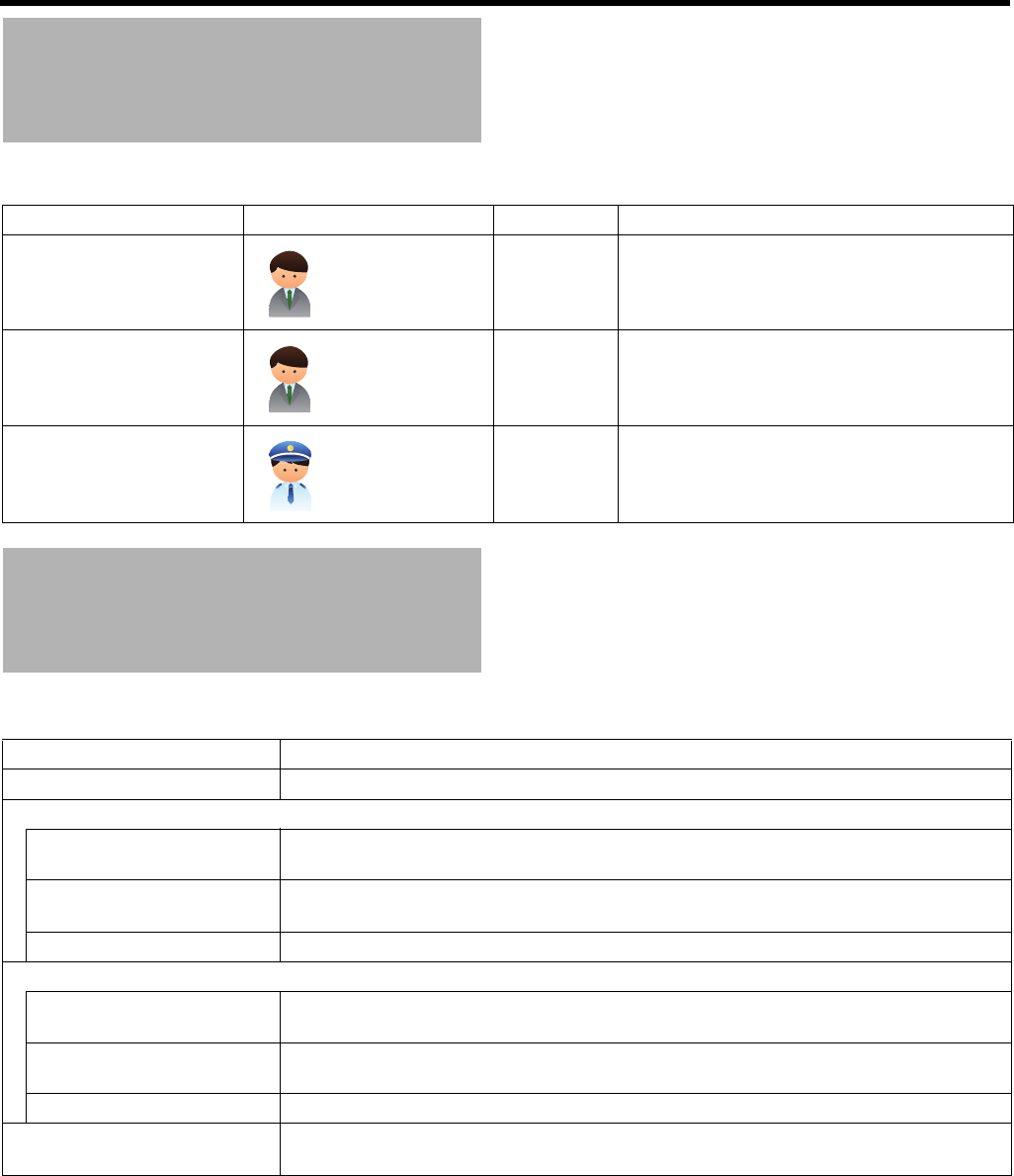
17
The structure of manuals for this unit is as follows.
The structure of this manual is as follows.
䡵Legend of symbols in this manual
Caution Indicates precautions for the operation.
Note Indicates useful information regarding functions and limitations on use.
A Indicates the reference page and reference item.
Structure of Manuals
Name of manual Intended reader Format Description
Set Up Guide System
administrators
and operators
Booklet Installation and setup procedures for this unit,
and basic setup and operation procedures for
this unit, management software and viewer
necessary for operations
INSTRUCTIONS (present
document)
System
administrators
and operators
HTML, PDF
(Integrated in
this unit)
Installation and setup procedures for this unit,
and details of setup and operation procedures
for effective use of this unit
Quick Reference (For
monitoring )
Monitoring
operators
Booklet The most fundamental operation procedures for
the viewer necessary for monitoring works
Structure of This Manual
Item Description
Getting Started (APage 2) Describes precautions for proper use of this product, etc. Be sure to read prior to use.
<Recorder Part>
Basics (APage 23) Describes basic operations and setup from installation and connection of this unit to
receiving images from the camera.
Applications (APage 38) Describes concrete setup procedures for specific operation types, including setup of the
operation at the time of alarm reception.
Reference (APage 80) Describes detailed setup items to master this unit and Management Application.
<Viewer Part>
Basics (APage 132) Describes procedures from installation of the viewer to a computer to basic setup for
monitoring.
Applications (APage 155) Describes viewer setup procedures for specific operation types, including screen
customization.
Reference (APage 163) Describes detailed setup items to master Smart Client.
Others (APage 180) Indicates compatible devices, recording time, and default value list, as well as
troubleshooting actions and specifications of this unit.
18
Getting Started
The workflow from installation of this unit to system operations is as follows.
Caution:
●Install the network cameras and set the IP addresses, etc. before installation and setup of this unit.
Workflow from Installation
to Operations
For operators
and
administrators
Install Install this unit to an EIA rack or the like. Page 24
T
Connect Connect devices necessary to operate this unit such as a monitor
and a mouse, and devices essential to configure the security
system such as a network cable and other warning system(s).
Page 25
T
Switch on the power of this unit After connecting necessary devices, switch on the power of this
unit.
Page 29
T
Connect this unit to the network Make the network settings on the unit, and connect it with the
cameras and computer.
Page 31
T
Configure basic system settings Register the cameras and configure settings to show images from
the cameras on the screen.
Page 32
T
Configure settings for specific
operation type
Configure settings for the intended purpose. Page 38
T
Use the viewer Set the contents to be displayed in the view in accordance with the
surveillance plan.
Page 132
For monitoring
operators
Operate Use the viewer to view live images from the cameras and search for
recorded images to play back.
Save recorded images to Desktop or other locations as necessary.
Page 132
For operators
and
administrators
Maintenance and system expansion System maintenance and configuration changes (addition of
camera and HDD, etc.) are possible. For the list of setup items of
this unit and Milestone application, refer to the “Reference.”
Page 80
Page 163
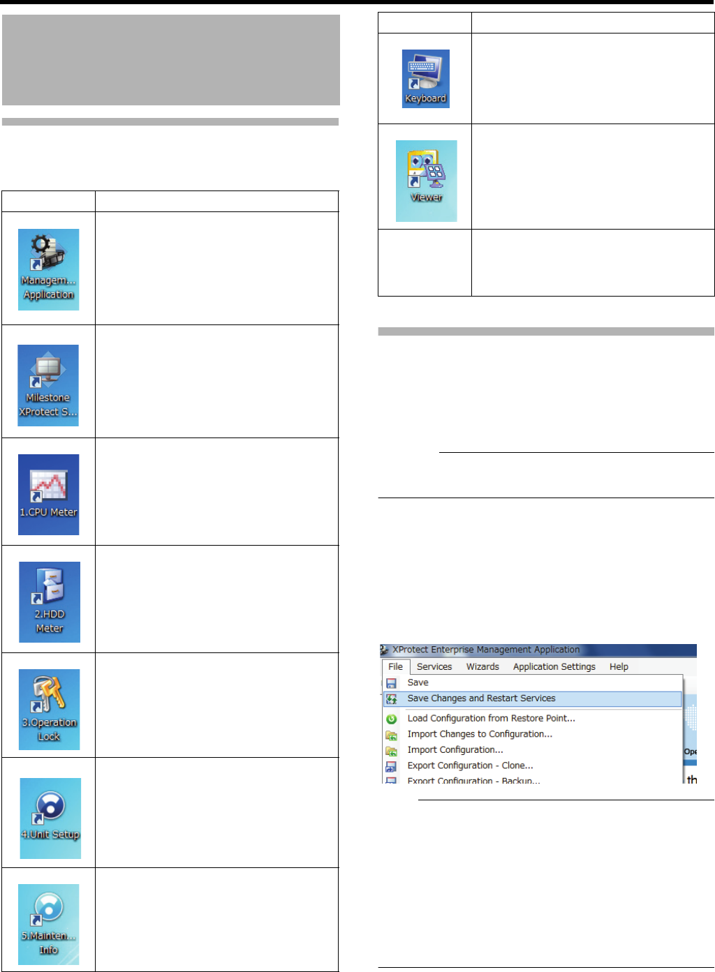
19
Overview of the Software
The following software is used with this unit.
Notices for Changing Settings
If you specify wrong settings, this unit may not operate
properly.
●Before you change setting, it is recommended to save unit
settings and settings of Management Application.
(APage 78 "Saving/Restoring Settings")
Caution:
●Never turn off the power while saving settings of
Management Application.
䡵When you change settings of Management
Application
When you have changed settings of Management
Application, save the settings, then restart the service.
otherwise, the new settings are not applied.
Save the settings and restart the service from the [File] menu
of Management Application.
Note:
●You can also restart the service from [Services] in
[Advanced Configuration]. (APage 113 "Services") In
addition, when you shut down Management Application,
the screen to select whether to save the settings or restart
the service is displayed. (APage 33 "To close
Management Application") Make sure to select "Save
changes - restart services" in this case.
●If you change settings of Management Application while
Smart Client is on, close Smart Client and restart the
service.
About the Software Used
with This Unit
Software Overview
Starts up XProtect Enterprise
Management Application. XProtect
Enterprise Management Application is
software to perform settings of the
monitoring system using XProtect
Enterprise. This software is referred to as
"Management Application" in this manual.
Starts up XProtect Enterprise Smart
Client. XProtect Enterprise Smart Client
is a software to view live or recorded
images with the monitoring system using
XProtect Enterprise. This software is
referred to as "Smart Client" in this
manual.
Starts up the CPU meter. This software
displays the load factor of this unit. By
default, the CPU meter appears on the
upper left of the desktop automatically
when you start up this unit.
Starts up the HDD meter.
This software displays the HDD usage.
Locking/unlocking the operation of this
unit.
Starts up unit settings menu.
You can perform settings of items other
than those with Management Application.
Starts up maintenance information menu.
You can display or save information such
as the runtime of this unit.
Starts up the screen keyboard.
Use this software to enter characters
using the mouse.
You can view the data exported in
database format.
Intel ® Rapid
Storage
Te c h no l o g y
This software is used to construct RAID.
Click [Start], [All Programs], [Intel],
[Intel ® Rapid Storage Technology] in this
order to start up.
Software Overview
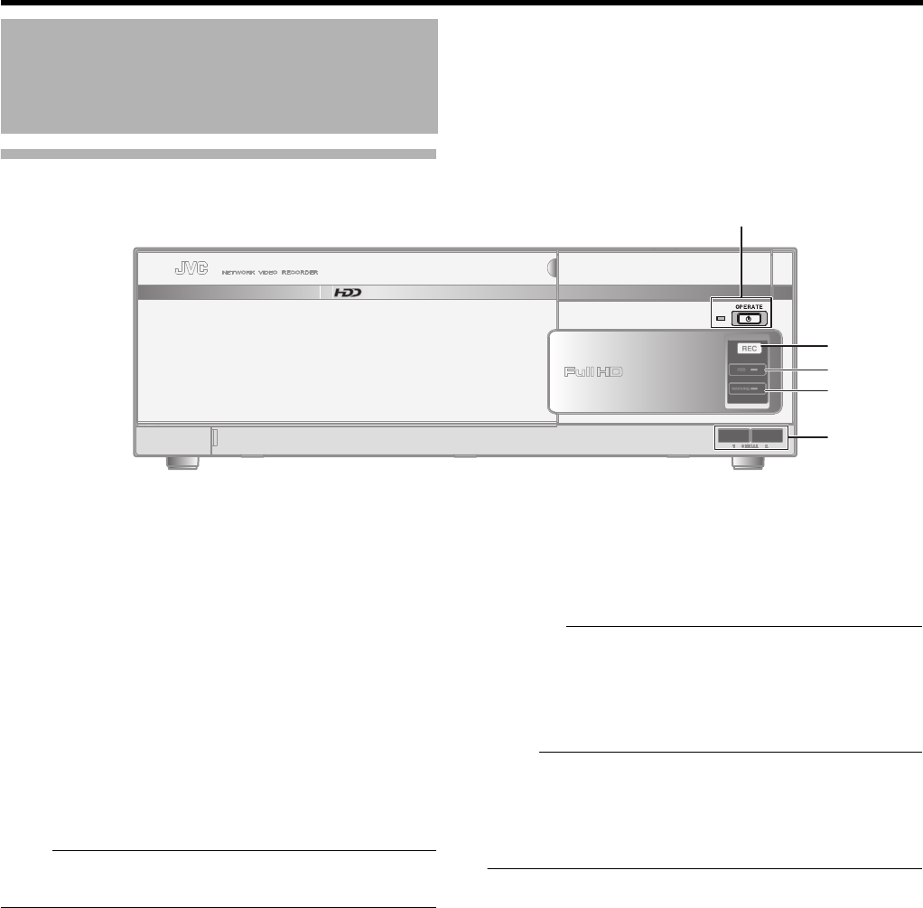
20
Getting Started
Front
A[OPERATE] Button/Indicator
Switches operation on or off. Press the button to turn
operation ON and hold down the button to turn operation
OFF. The indicator blinks while the recorder is starting up or
shutting down. When the starting up operation is complete,
the indicator stops blinking and is lit.
B[REC] Indicator
Lights up during recording.
C[HDD] Indicator
Lights up when the built-in hard disk drive is accessed.
D[WARNING] Indicator
Lights up when an error occurs in the hardware.
Note:
●Error types: A Page 195
●How to turn off: A Page 129
E[SERIAL1/2] Terminals
For connecting the communication control terminals of a
USB mouse (sold separately), USB flash memory (sold
separately) or UPS (sold separately).
Caution:
●Attach the serial port cover supplied with this product if
this port is not in use.
●This product may malfunction due to the presence of
static electricity. Remove any static before starting
operation.
Note:
●Use the SERIAL terminal or [eSATA] terminal on the rear
panel for additional HDD connection. (APage 21)
●For connection of external devices, consult your nearest
JVC KENWOOD dealer. You can also check on our
website.
Part Names and Functions
AA
BB
CC
DD
EE
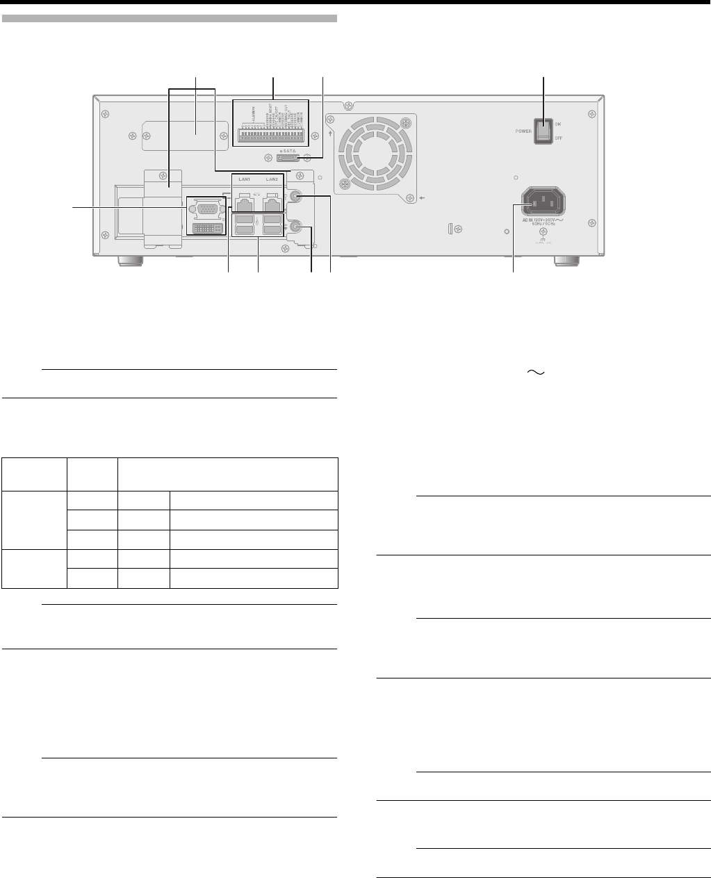
21
Rear Panel
FMonitor Output Terminals (D-sub 15pin, DVI)
Outputs the recorded images, live images or the setup
screen.
Note:
●The DVI terminal emits only digital signals.
GLAN1/LAN2 Terminals
Connect to the network using a LAN cable.
Note:
●For how to use LAN1/LAN2, refer to “Proper Use of LAN1/
LAN2” (APage 119).
HSERIAL Terminal
For connecting the communication control terminals on a
USB mouse (sold separately), USB flash memory (sold
separately), UPS (sold separately) or additional HDD (sold
separately).
Note:
●For connection of external devices, consult your nearest
JVC KENWOOD dealer. You can also check on our
website.
IAudio Output Terminal
Connect to an audio output device such as a speaker.
JAudio Input Terminal
Connect to an audio input device such as a plug-in
microphone.
K[AC IN 120V - 240V 50Hz/60Hz] power input
terminal
Connect to an AC120 V to AC240 V outlet using the power
cable supplied.
L[POWER] switch
Switches the power on or off.
Note:
●Be sure to press and hold down the [OPERATE] button on
the front panel to shut down the system before switching
off the power supply.
M[eSATA] Terminal
Connect to an additional HDD (sold separately).
Note:
●For details on additional HDDs you can connect to this
unit, consult your nearest JVC KENWOOD dealer. You
can also check on our website.
NSignal input/output terminals
For operating the unit using external alarm signals or signals
received from external devices, or for operating external
devices by outputting signals.
Note:
●Diameter of applicable cable: AWG22 to AWG28
OConnector cover
Note:
●Do not remove the cover.
NNMMLL
KKJJIIHH
F
GG
OO
Indicator
position
Color Status
Left - Off Communication at 10 Mbit/s.
Green On Communication at 100 Mbit/s.
Orange On Communication at 1 Gbit/s.
Right - Off Not connecting to the network.
Yellow Blinking Communication is in progress.
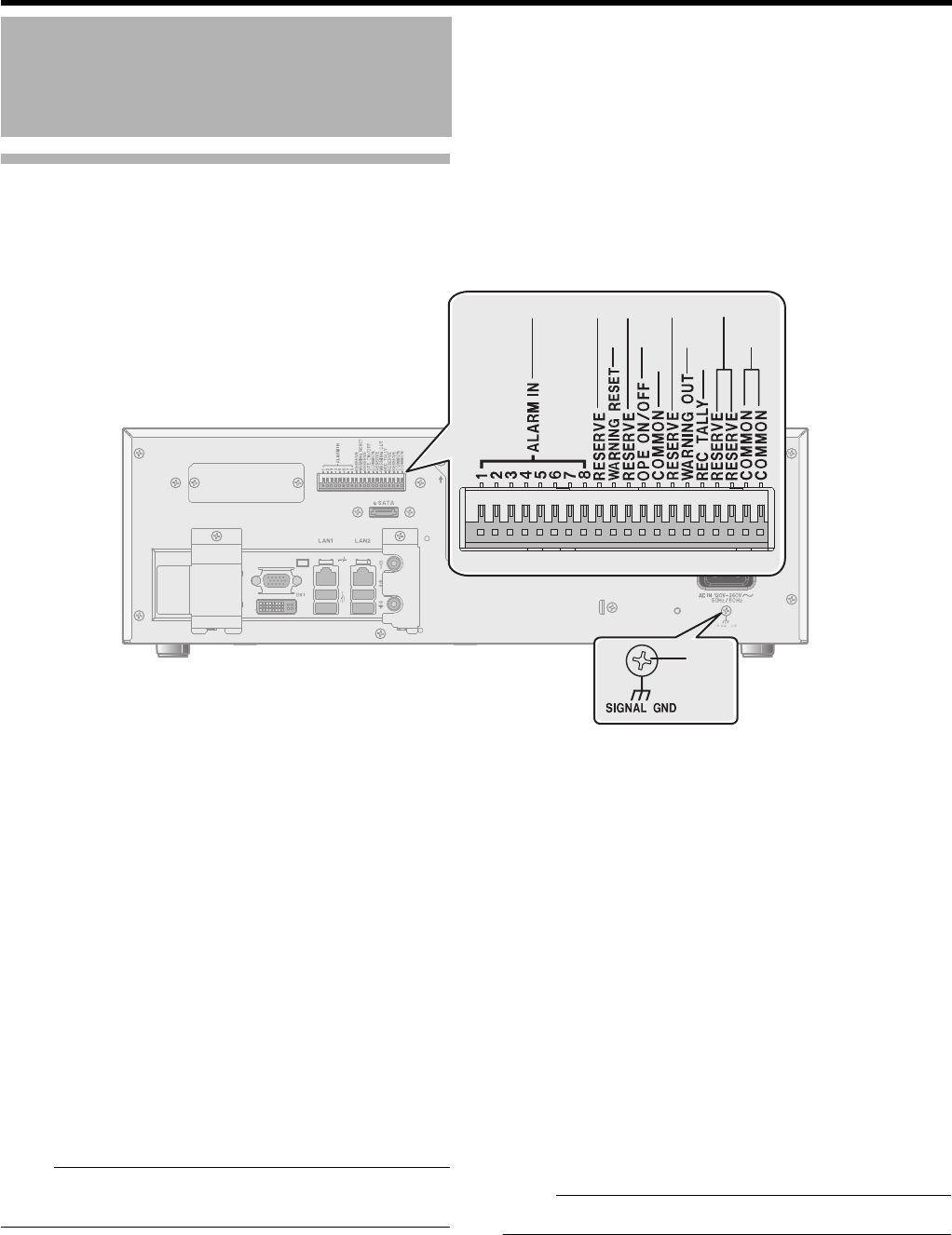
22
Getting Started
Rear I/O Terminals
䡵Input ports (APage 27)
P[ALARM IN 1 to 8] alarm input terminals 1 to 8
When a signal is input to these terminals, an alarm event
occurs and you can activate alarm recording and/or change
the direction of a PTZ camera. (APage 46 "Events and
Actions")
Q[RESERVE] Terminal
Reserved.
R[WARNING RESET] Warning Reset Input
Terminal
Output from the Warning Output Terminal is stopped when a
signal is input to this terminal during output of the Warning
Out signals.
S[OPE ON/OFF] Operate ON/OFF terminal
Switches between OPERATE ON or OFF when a signal is
input to this terminal.
Note:
●The "OPERATE OFF" works even during Operation Lock
( A Page 116).
䡵Output Ports (APage 27)
T[COMMON] Signal Ground Terminal
This is a common ground terminal. Connect it to the signal
ground terminal on the connected device.
This can be used when there are insufficient common ground
terminals.
U[WARNING OUT] Warning Output Terminal
(APage 195)
Outputs signals when an error such as an HDD malfunction
occurs.
V[REC TALLY] recording status output terminal
Outputs the recording status of this unit.
W[SIGNAL GND] signal ground terminal
This is a common ground terminal. Connect it to the signal
ground terminal on the connected device.
This can be used when there are insufficient [COMMON]
Signal Ground Terminals T.
Note:
●Do not use this terminal for protective earthing.
Part Names and Functions
(continued)
WW
QQQQQQQQ
SS
TT
TTUURR
VV
PP

Recorder Part
Basics
This chapter describes procedures for basic operations of this unit (recorder) and basic setup for
the surveillance system.
Caution:
●Never turn off the power while saving settings of Management Application.
●When you change settings of Management Application, restart the service; otherwise, the new settings are not applied.
(APage 19 "When you change settings of Management Application") In addition, if you change settings of Management
Application while Smart Client is on, close Smart Client and restart the service.
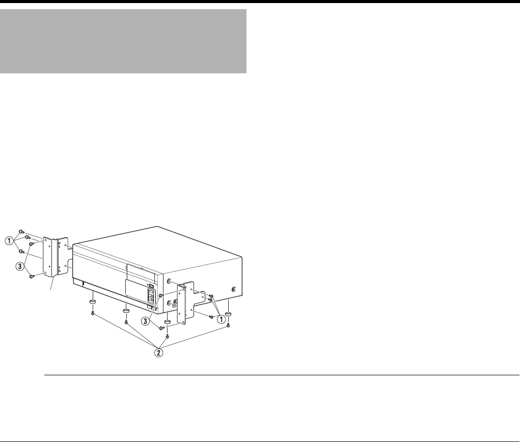
24
<Recorder Part> Basics
This section describes procedures to use the supplied rack mount bracket to mount this unit to the EIA rack. For the installation to
the rack, consult the specialist or dealer.
1 Mount the rack mount bracket using screw A
●Use the 6 screws (M4 x 11 mm) supplied to fasten this unit on both sides.
2 Remove the foot screws B (4 pcs) on the bottom of the unit
●Remove the foot.
3 Mount to the rack using screws C
●Use the 4 screws (M5 x 10 mm) supplied to fasten this unit to the rack.
Caution:
●Do not place any object on this unit when it is mounted to the rack. Doing so may cause it to lose balance and drop or fall,
resulting in injuries or damage.
●
When mounting more than one of this unit to the rack, make sure to mount each at a distance that is at least equivalent to one U.
●When remounting the removed foot, make sure to use the same screws (M3 x 6 mm). Using a longer screw may cause
malfunction.
Mounting to a Rack
Rack mount
bracket
4 screws
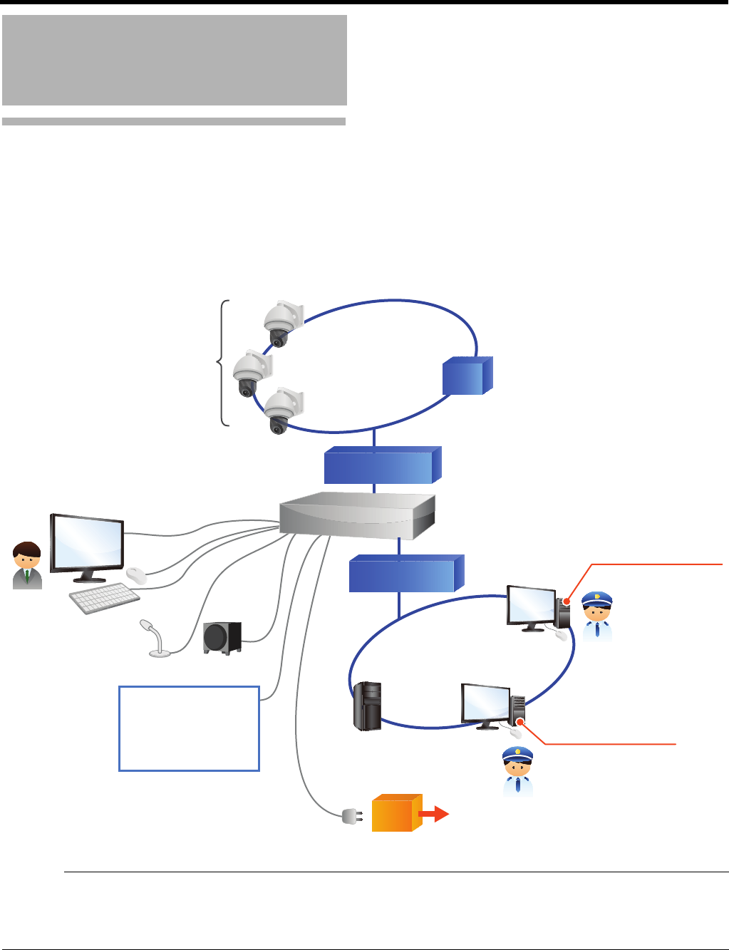
25
Basic System Configuration
This unit can be used to build the following monitoring system configuration.
●32 (VR-X3200U)/16 (VR-X1600U) cameras for live image monitoring and image recording and playback (With additional
camera licenses, VR-X3200U and VR-X1600U may monitor up to 64 and 32 cameras, respectively)
●Check of recorded images with VGA or DVI monitor
●Audio recording and playback
●Playback of microphone audio sounds through speaker of the specified camera(s)
●Recording by alarm
●Remote monitoring using a computer
Caution:
●Turn off all devices before connecting.
●Do not connect a faulty switching hub or router, or an exhausted network cable. Otherwise, the system may malfunction.
●When you use a NAS or UPS, consult your nearest JVC KENWOOD dealer for details on the compatibility with this unit. You
can also check on our website.
Connecting
VR-X3200U
VR-X1600U
Warning Equipment
Sensor
Warning lamp/siren
Warning canceling
device etc.
NAS
Switching HUB
Switching HUB
UPS
LAN1
LAN2
Monitor
Mouse
Keyboard
SpeakerMicrophone
Surveillance
computer
Surveillance
computer
Time server
(NTP server)
Smart Client
(Monitoring software)
Smart Client
(Monitoring software)
Network cameras
Power outlet
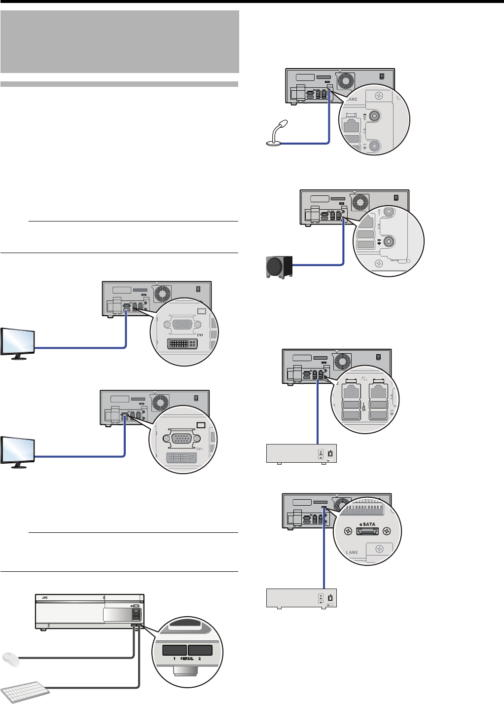
26
<Recorder Part> Basics
Devices Connected to Terminals of
This Unit
䡵Connecting a monitor
Connect a monitor to the RGB output terminal or DVI output
terminal on the rear panel.
Recommended monitor resolutions are listed below:
●1024 x 768
●1280 x 768
●1280 x 1024
●1600 x 1200
●1920 x 1080
Note:
●Some monitor resolutions above may not be available
depending on the monitor you use.
䢇DVI monitor (Digital only)
䢇VGA monitor
䡵Connecting a mouse and keyboard
This unit is used with a mouse.
For setup, use a keyboard connected to the SERIAL terminal
on the front panel.
Note:
●Characters may also be entered using the built-in on-
screen keyboard. For how to use the on-screen keyboard,
see "Using the On-screen Keyboard" (APage 30).
䡵Connecting a microphone and speaker
A microphone and speaker on the camera side allows for
speech communication.
䢇Microphone
䢇Speaker
䡵Connecting additional HDDs
The SERIAL terminal or eSATA terminal on the rear panel
can be used for additional HDD(s).
䢇SERIAL terminal
䢇eSATA terminal
Connecting (continued)
27
䡵Connecting external security devices
Connect devices other than network devices (infrared sensor and warning system, etc.) to the signal input terminals on the rear
panel.
䢇Rear input terminals
Terminal Remarks
[ALARM IN]
Note:
●Set the impedance at the output end to 10kK or lower.
Make Contact Input
[WARNING
RESET]
Note:
●Set the impedance at the output end to 10kK or lower.
Make Contact Input
[OPE ON/OFF]
Note:
●Set the impedance at the output end to 10kK or lower.
●The "OPERATE OFF" works even during Operation Lock. ( A Page 116)
Make Contact Input
[REC TALLY]
[WARNING OUT]
The make contact is formed using the individual output terminals and the
[COMMON] terminal. Turning off the power of this unit switches the output of the
output terminals to break.
Open collector output
(DC15V, 10 mA and
below)
250ms or more
250ms or more
Make Break
䢇Name of input event:
JVC NVR ALARM IN1 to 8 MAKE
(Generic events)
䢇Name of input event:
JVC NVR ALARM IN1 to 8 BREAK
(Generic events)
250ms or more
1s or more
Approx.
50ms
OPE OFF
OPE ON
Make Output
(External Pull-up
Level)
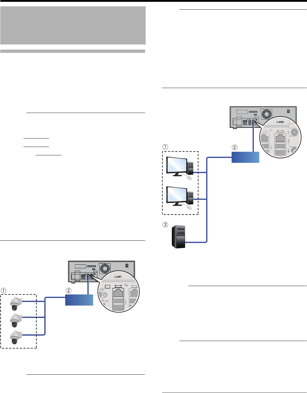
28
<Recorder Part> Basics
Devices Connected Through a
Network
This unit is connected with network cameras and
surveillance computers through the network.
This unit has two network terminals; one for connecting to
network cameras (LAN1), and one for connecting to
surveillance computers (LAN2).
Caution:
●Make sure to use LAN1 and LAN2 for different segments*.
Example:
LAN1: 192.168.0.253
LAN2: 192.168.1.253
* Segment: Underlined sections
●LAN1 and LAN2 cannot communicate with each other. It
is not possible to configure settings of cameras connected
to LAN1 from a surveillance computer connected to
LAN2. Connect a computer for camera setup to LAN1 in
order to configure settings for cameras connected to
LAN1.
●LAN1 and LAN2 are non-QoS-compliant. Audio sounds
may not be played back properly depending on the line
status.
●Do not connect a faulty switching hub or router, or an
exhausted network cable. Otherwise, the system may
malfunction.
䡵Connecting to network cameras (LAN1)
ANetwork cameras
BSwitching hub
Caution:
●Install cameras and setup IP addresses in advance.
●Do not connect LAN1 to the Internet. Important camera
images may not be saved depending on conditions such
as Internet congestion and relay status.
It is recommended to make it a dedicated network to
ensure recording performance. Also, the camera network
of LAN1 must be the same segment (address conversion
such as NAT and NAPT and a router are not used).
Note:
●For protocols and port numbers used by network
cameras, refer to the instruction manual of the network
cameras.
●The default IP address of LAN1 is “192.168.0.253.” The
default value may be changed in [Network and Internet] in
[Control Panel] (APage 31).
●With separately-sold camera licenses, the number of
cameras that can be connected may be increased to 64
(VR-X3200U) or 32 (VR-X1600U) (APage 118). For
purchase of additional licenses, consult an authorized
dealer or a JVC KENWOOD service center.
䡵Connecting to surveillance computers (LAN2)
AComputer
BSwitching hub
CTime server (NTP server)
Caution:
●When connecting the LAN2 side to the internet and using
in on the surveillance computer, global IP acquisition and
VPN connection may require a contract with a separate
telecommunications carrier. Also, it is necessary to set the
broadband router to connect to the internet.
●To use LAN2 on surveillance computer by connecting to
the Internet, an IP masquerade setup is necessary.
Note:
●Protocols and port numbers used are as follows:
●Surveillance computer: HTTP 80
●Main sending: SMTP 25, and POP 110
●Time synchronization: NTP 123
●The default IP address of LAN2 is “192.168.1.253.” The
default value may be changed in [Network and Internet] in
[Control Panel] (APage 31).
Connecting (continued)
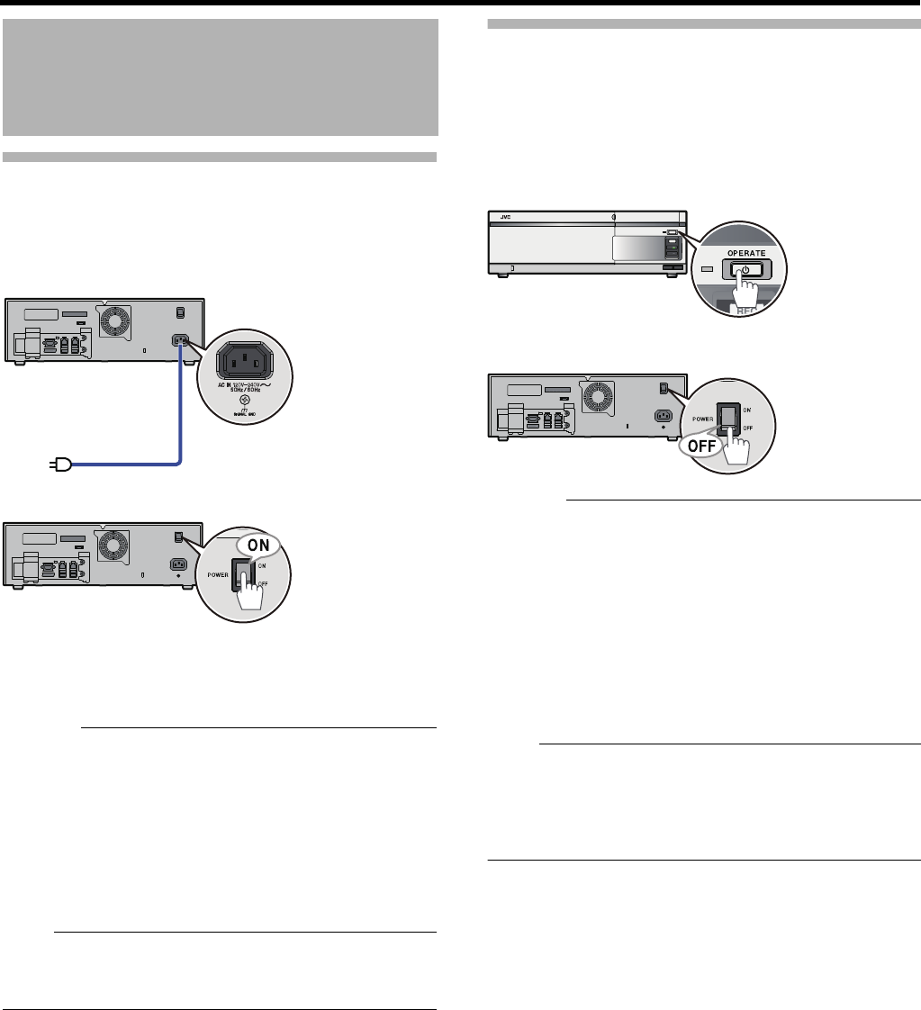
29
Switching the Power On
1 Connect a power cord
●Connect to an AC 120 V to 240 V (50Hz/60Hz) outlet
using the power cable supplied.
2 Turn the power switch on the rear panel “ON”
The system check starts and the Operate indicator blinks.
When the system check is completed, the Operate
indicator lights up and operations are enabled (the system
is activated).
Caution:
●Do not turn the power switch “OFF” during system check
or when the system is activated. Otherwise, it may break
down. In addition, the power switch must be turned “OFF”
before the power cord is disconnected.
●It is recommended that a UPS (uninterruptible power
supply) be used in preparation for power failure. For
details on the UPS you can connect to this unit, consult
your nearest JVC KENWOOD dealer. You can also check
on our website.
Note:
●Press the [OPERATE] button on the front panel if the unit
does not start even when the power switch on the rear
panel is turned “ON”.
Switching the Power Off
1 Press and hold down the [OPERATE] button for
about 2 seconds to shut down the system
The shutting down operation starts and the Operate
indicator blinks. When the system is shut down, the
screen becomes blank and the Operate indicator is turned
off.
2 Turn the power switch on the rear panel “OFF”
Caution:
●If the system can not be shut down normally due to power
failure or the like, recorded images may not be played
back properly.
●Be sure to turn off the power switch on the rear panel only
after pressing and holding down the [OPERATE] button on
the front panel to shut down the system. Turning off the
power switch on the rear panel with the system being
activated may cause malfunction.
●After you switch the power off, do not move the unit for at
least one minute; otherwise, the internal HDD may break
down due to a shock.
Note:
●The system can also be shut down by selecting [Shut
down] from [Start] button on the desktop.
●The system may also be activated/shut down from the
device connected to the [OPE ON/OFF] terminal on the
rear panel. (APage 27 "[OPE ON/OFF]")
Switching the Power On/
Off
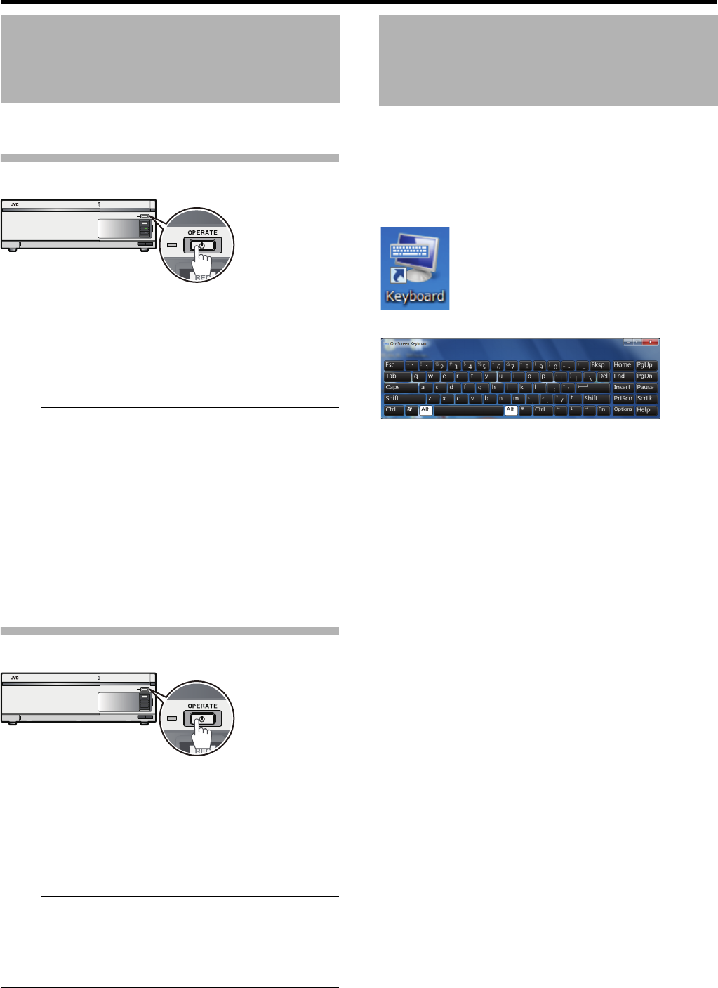
30
<Recorder Part> Basics
The system can be activated/shut down.
Activating the System
1 Press the [OPERATE] button (with the system
shut down)
The system check starts and the Operate indicator blinks.
When the system check is completed, the Operate
indicator lights up and operations are enabled (the system
is activated).
Note:
●The system is automatically activated when the power
switch on the rear panel is turned “ON”.
●When the login screen appears, enter the password to
login to the system. For details about setting the login
password, see "Setting the Password to Login to This
Unit" (APage 87).
●If a login password is set, the warning message
(APage 195) will not be displayed. In this case, the
[WARNING] indicator will light.
●If the [Smart Client] check box is selected in [StartUp
auto-display setting], (APage 81) the Smart Client is
launched when you successfully login.
Shutting Down the System
1 Press and hold down the [OPERATE] button for
about 2 seconds to shut down the system
The shutting down operation starts and the Operate
indicator blinks. When the system is shut down, the
screen becomes blank and the Operate indicator is turned
off.
Note:
●The system can also be shut down by selecting [Shut
down] from [Start] button on the desktop.
●The system may also be activated/shut down from the
device connected to the [OPE ON/OFF] terminal on the
rear panel. (APage 27 "[OPE ON/OFF]")
In addition to using a keyboard connected to the SERIAL
terminal on the front of this unit, characters may also be
entered using the on-screen keyboard.
1 Double-click the [Keyboard] button on the
desktop
The on-screen keyboard starts up.
2 Move the cursor over a character you want to
input and click the mouse button
Activating/Shutting Down
the System
Using the On-screen
Keyboard
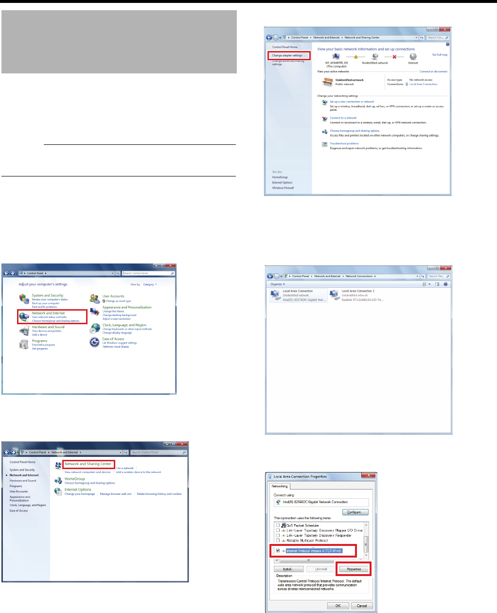
31
This section describes procedures to setup an IP address for
this unit and connect to the camera network (LAN1) and
monitoring PC (LAN2).
䢇Also setup an IP address for each of LAN1 and LAN2.
Caution:
●Install and setup network cameras before network setup
for this unit.
1 Click the [Start] button on the desktop, followed
by clicking [Control Panel]
The control panel opens up.
2 Click [Network and Internet]
●If [Category] is not displayed, select [Category].
The [Network and Internet] window appears.
3 Click [Network and Sharing Center]
4 Click [Change adapter settings]
5 Right click on an adapter and click [Properties].
●To setup LAN1: Select AIntel(R) 82578DM Gigabit
Network Connection.”
●To setup LAN2: Select ARealtek RTL8168D/8111D
Family PCI-E Gigabit Ethernet NIC (NDIS 6.20).”
6 Select [Internet Protocol Version 4 (TCP/IPv4)]
and click [Properties]
Connect This Unit to a
Network
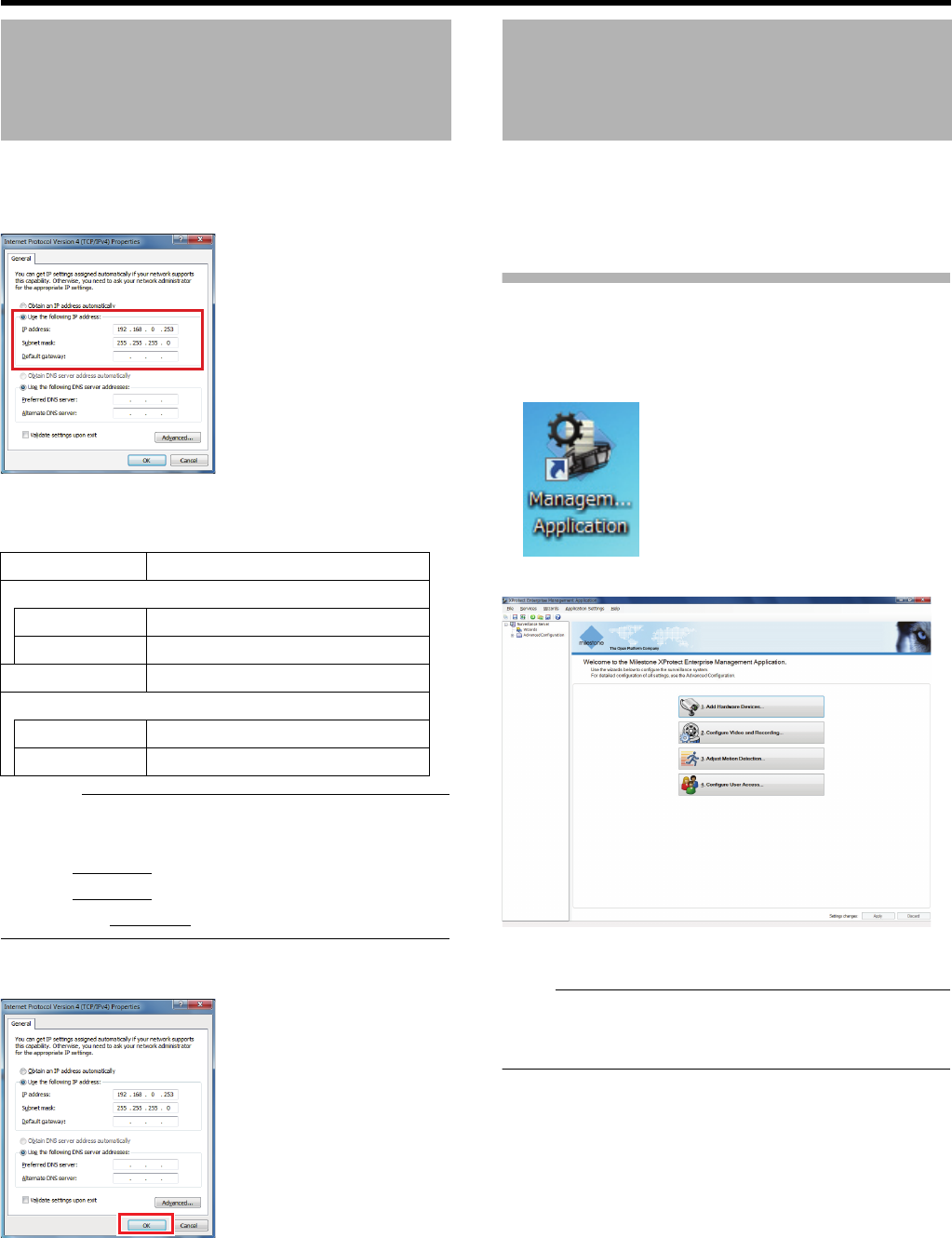
32
<Recorder Part> Basics
7 Enter the IP address, subnet mask, and default
gateway
●Default settings are indicated below. To set values
other than the default values, consult your network
administrator.
Caution:
●Make sure to use LAN1 and LAN2 for different segments*.
Example:
LAN1: 192.168.0.253
LAN2: 192.168.1.253
* Segment: Underlined sections
8 Click [OK]
The network has been configured.
Configure monitoring system settings such as registering a
camera or record settings using Management Application.
Follow the instructions from the wizard of XProtect
Enterprise to configure basic settings.
Starting Up Management
Application
1 Double-click [Management Application] on the
desktop
The top screen appears.
Follow the instructions of the wizard to register cameras and
configure basic settings of the cameras and recording.
Note:
●Settings of [Adjust Motion Detection...] and [Configure
User Access...] should be configured only when it is
necessary. (A Page 44, A Page 66)
Connect This Unit to a
Network (continued)
Item Default setting
IP address
LAN1 192.168.0.253
LAN2 192.168.1.253
Subnet Mask 255.255.255.0
Default gateway
LAN1 (None)
LAN2 192.168.1.254
Configuring Basic
Monitoring System
Settings
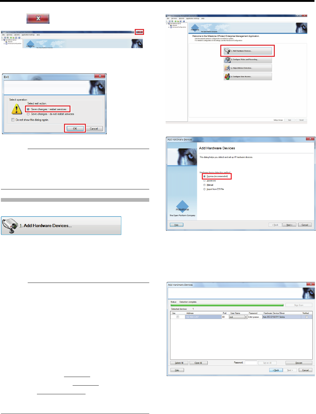
33
䡵To close Management Application
1 Click [ (Close)]
2
Select [Save changes - restart services], and click
[OK].
Management Application is closed.
Caution:
●Never turn off the power while saving settings of
Management Application.
●When you change settings of Management Application,
restart the Management Application service; otherwise,
the new settings are not applied.
Connecting Cameras
Use the [Add Hardware Devices...] wizard to register
cameras in the network with the system and enable setup
and operations from NVR.
●User name and password for each camera are necessary
for camera registration. Please check them in advance.
For details, refer to the instruction manual of the cameras.
Caution:
●You need to configure an IP address for each network
camera in advance.
●By default, the IP address for LAN1 is 192.168.0.253 and
the subnet mask is 255.255.255.0.
●It is necessary to set the IP address of the network
camera in the same segment* as LAN1 of this unit. If the
camera and this unit are not on the same network, the
camera cannot be registered. Confirm that the IP address
of the camera and LAN1 are in the same segment. If they
are in different segments, consult your network
administrator.
Example: When the subnet mask is 255.255.255.0
IP address of this unit: 192.168.0.253
IP address of the camera: 192.168.0.100
* Segment: Underlined sections
●Do not set multiple devices to the same IP address.
Otherwise, settings cannot be made correctly.
1 Click [Add Hardware Devices...]
The wizard will start.
●Check to ensure that the [Express (recommended)]
check box is selected.
2 Click [Next]
Automatic detection of cameras connected to the network starts.
When the automatic detection is completed, a list of
cameras detected appears.
●
Depending on the network configuration, the camera may
not be detected automatically. Click [Rescan] when there
is any camera that is not shown in the list. When the
camera is still not shown, register the camera manually.
(
A
Page 117 "Manually Registering a Camera")
●VN-C215U will not be detected automatically. Please
register it manually. (APage 117 "Manually
Registering a Camera")
●If the user name and password of a camera have been
changed from the initial settings, there is a chance that
the camera will not be automatically detected.
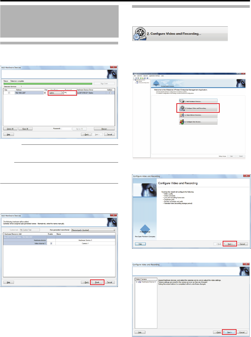
34
<Recorder Part> Basics
Connecting Cameras (continued)
3
Enter the user name and password of the cameras
Caution:
●You cannot proceed to the next step if the user name and
password are not correct.
Note:
●If the password is the same for all cameras, enter the
password in the [Password] field in the lower part and click
[Set on All].
4 Click [Next]
5 Confirm the cameras to register and click
[Finish]
Return to the top window.
Registration of the cameras has been completed. Now you
may receive images from the cameras. Next, configure
settings for images and recording of each camera.
Configuring Settings of Cameras
Connected
Use the [Configure Video and Recording...] wizard to
configure settings of recording schedule and frame rate
(image quality) for each camera.
1 Click [Configure Video and Recording...]
2 Click [Next]
3 Click [Next]
Configuring Basic
Monitoring System
Settings (continued)
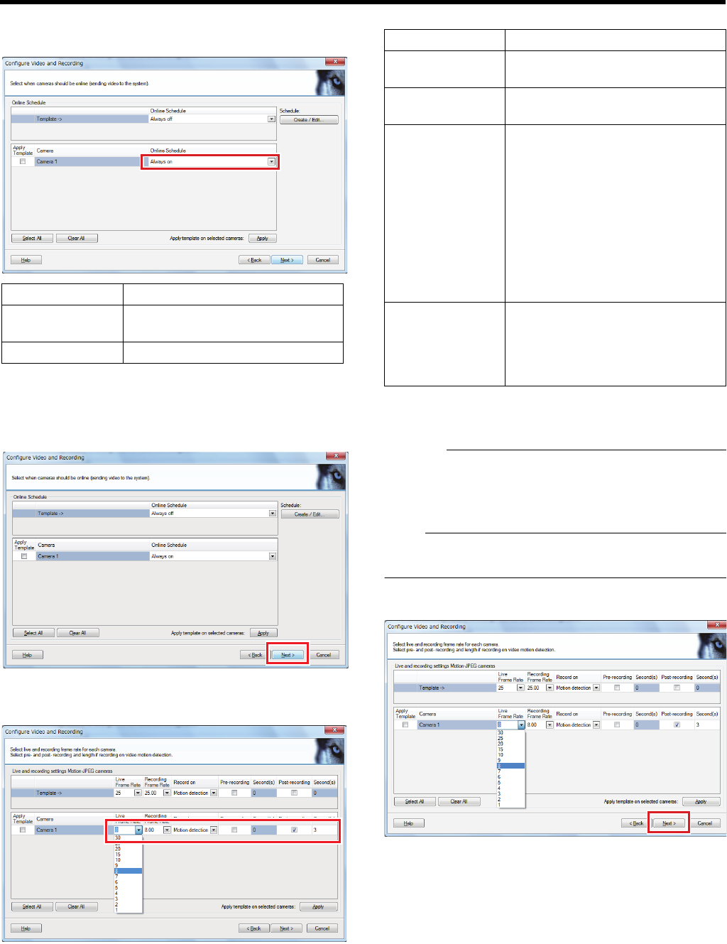
35
4 Make the settings to receive images for each
camera
●Select the [Apply Template] check box and click [Apply]
to apply the settings selected in [Template - >] in the
upper part to all selected cameras.
5 Click [Next]
The frame rate setup screen appears.
6 Specify the frame rate and recording conditions
Configure the following items in order.
●Select the [Apply Template] check box and click [Apply]
to apply the settings selected in [Template - >] in the
upper part to all selected cameras.
Caution:
●Be sure to set the frame rate so that the total frame rate
does not exceed the performance capacity of this unit. For
the performance of this unit, see ARecording/Displaying
live images/Distribution performanceB (A Page 196).
Note:
●[Event] or [Event and motion detection] in [Record on] is
displayed when an event is specified.
7 Click [Next]
Item Description
Always on Always receive images from the
camera.
Always off Receive no images from the camera.
Item Description
Live Frame Rate For specifying frame rate for live
display.
Recording Frame
Rate
For specifying frame rate for
recording.
Record on Set the recording conditions.
●Always: records constantly.
●Never: select when only recording
manually.
●Motion detection: records when
motion is detected.
●Event: records when an event
occurs.
●Event and motion detection:
records when an events occurs
and motion is detected.
Pre-recording/
Post-recording
For specifying units of seconds
before and after the motion/event
when recording is set to start by
motion detection or an event
occurring in [Record on].
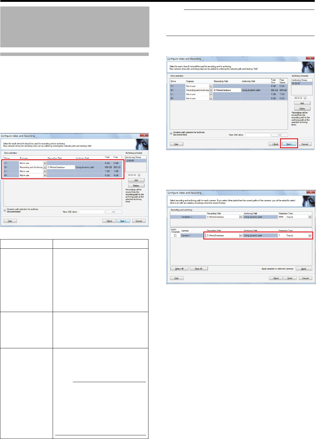
36
<Recorder Part> Basics
Configuring Settings of Cameras
Connected (continued)
8 Specify the type and storage location of
recording data to be stored in each drive
●This unit stores images received from cameras in a
predefined folder first (recording), then transfers and
saves (archives) the recording data to another location.
Specify a drive and storage folder location (path) for
each.
Configure the following items in order.
Note:
●Be sure to specify both a recording path and an archive
path; otherwise, an error occurs and you cannot continue
to the next step.
9 Click [Next]
The data location setting screen for each camera
appears.
10 Specify the data storage location and retention
time for each camera
●Each drive cannot be used for anything other than that
specified for “Purpose” in step 8.
●Select the [Apply Template] check box and click [Apply]
to apply the settings selected in [Template - >] in the
upper part to all selected cameras.
Configuring Basic
Monitoring System
Settings (continued)
Item Description
Purpose For specifying the usage of each
drive.
●Recording and Archiving: Select
this check box to use the drive for
both recording and archiving.
●Recording: Select this check box
to use the drive only for recording.
●Archiving: Select this check box to
use the drive only for archiving.
Recording Path For specifying the location of
recording data storage. This item is
available when [Recording] or
[Recording and Archiving] is selected
in [Purpose].
Archiving Path For specifying the location of archive
storage. This item is available when
[Recording and Archiving] or
[Archiving] is selected in [Purpose].
Note:
●By default ([Using dynamic path]),
a path is automatically
determined. To save data in any
other location, deselect the
[Dynamic path selection for
archives (recommended)] check
box to specify a storage location.
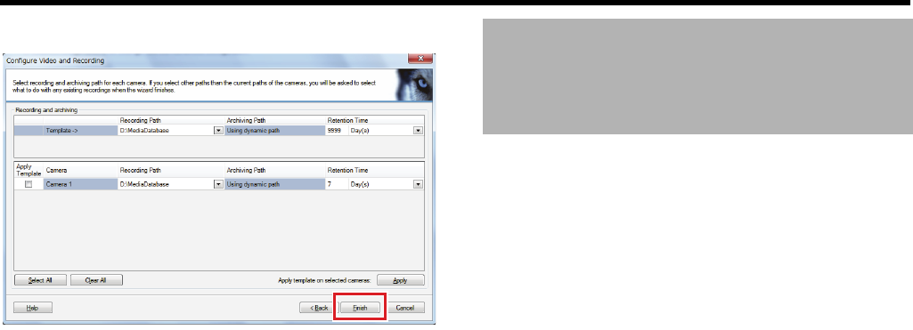
37
11 Click [Finish]
Return to the top window.
In the end, restart the service so that the specified settings
are applied. (APage 33 "To close Management
Application")
Basic setup of the monitoring system has been finished. Now
you can receive, view and record images from installed
cameras.
To ensure sufficient data storage on this unit, be sure to add
additional HDD and make the appropriate saving method
settings.
䡵Building a RAID10 configuration
By adding internal HDD you can increase the storage
capacity.
Furthermore, the data duplication and dispersion achieved
through using RAID allows for more secure data and high
speed saving.
As this unit supports RAID10, you can build a RAID10
configuration to achieve the maximum recording
performance (frame rate).
For adding internal HDD and building a RAID configuration,
see "Adding an HDD" (APage 71) and "Building a RAID
Configuration" (APage 72).
䡵Setting the recording data and archiving
destination to the same drive
By setting the recording data and archiving destination
(recording path/archiving path) to the same drive, you can
reduce the strain on this unit when moving data.
Set the recording/archiving path in [Cameras and Storage
Information] in [Advanced Configuration] of Management
Application. (APage 100)
䡵Making settings to erase old recordings
By setting an appropriate storage period for recording data,
old recording data will be erased at fixed intervals to retain a
constant capacity.
Set the storage period for recording data in [Cameras and
Storage Information] in [Advanced Configuration] of
Management Application. (APage 100)
Making Full Use of
Recording Performance

Recorder Part
Applications
This chapter describes procedures for setup of PTZ camera and event actions according to
specific monitoring system operations. Perform settings using Management Application.
Caution:
●Never turn off the power while saving settings of Management Application.
●When you change settings of Management Application, restart the service; otherwise, the new settings are not applied.
(APage 19 "When you change settings of Management Application") In addition, if you change settings of Management
Application while Smart Client is on, close Smart Client and restart the service.
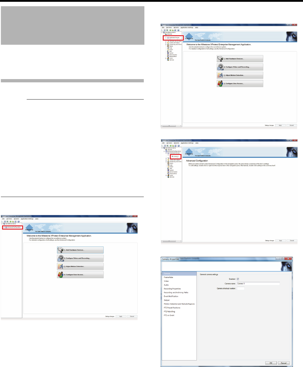
39
<Recorder Part> Applications
When cameras are compatible with the PTZ (pan, tilt and
zoom) functions, you can set the preset position from this
unit.
Defining a Preset Position
Caution:
●The preset position may be displaced by a few degrees for
some cameras.
●The configurable items may differ according to the camera
in use.
●When using VN-V685U/VN-V686U/VN-V686BU Series,
the preset position cannot be registered if the electronic
zoom feature of a camera is functioning. Please take note
that no error message will be displayed in such a case.
During PTZ preset setting, set [EZoom Limit] to “1” from
[PTZ page] of VN-V685U/VN-V686U/VN-V686BU to
prevent registration by mistake. For VN-686BU Series
users, in addition, set [PTZ Type] to [Type 3] on this unit.
For details, refer to [INSTRUCRTIONS] of VN-V685U/VN-
V686U/VN-V686BU Series.
1 Click [+] in [Advanced Configuration]
2 Click [+] in [Hardware Devices] and click [+] for
the hardware device name of a PTZ camera
3 Double-click a camera name
The [Camera Properties] window appears.
Defining a Preset PTZ
Position
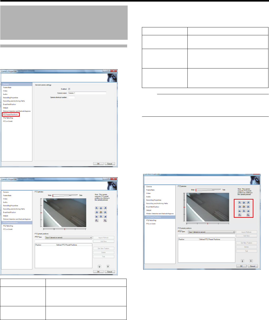
40
<Recorder Part> Applications
Defining a Preset Position (continued)
4 Click [PTZ Preset Positions]
The setting screen appears.
5 Select [PTZ Type]
The following three methods can be used to register a
preset position.
Note:
●When using a JVC camera, it is recommended to select
the more positionally accurate [Type 3]. (Not selectable
depending on the camera.)
6 When [Type 2] or [Type 3] is selected: Click
[Import/Refresh]
The preset position is imported and the list appears.
●The displayed order may differ to that set on the
camera.
7 When [Type 1] is selected: Determine the
camera position from [PTZ preview]
Defining a Preset PTZ
Position (continued)
Item Description
PTZ preview For moving the PTZ camera to the
desired position. You can check the
position on the screen.
PTZ preset
positions
For registering, deleting and testing
a PTZ camera position.
Item Description
Type 1 (stored on
server)
Set the preset position on this unit.
Type 2 (stored on
server)
Import the preset position set on the
camera into this unit. The preset
position is stored on this unit.
Type 3 (stored on
camera)
Import the preset position set on the
camera into this unit. The preset
position is stored on the camera.
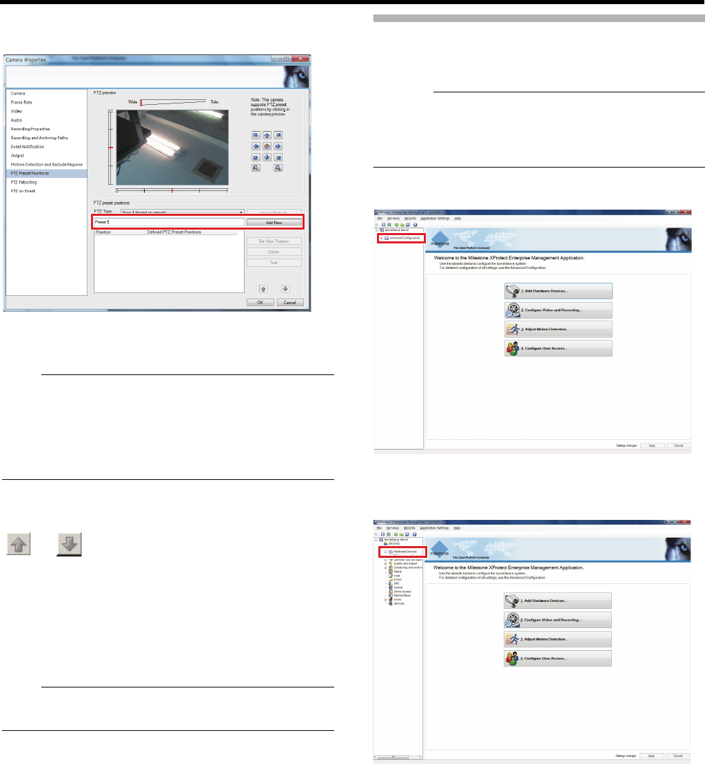
41
8 When [Type 1] is selected: Enter a name for the
preset position, and click [Add New]
The preset position is set and added to the list.
9 Click [OK]
Note:
●The position at the top of the list corresponds to Preset
Position 1.
●The number of preset positions that can be registered
may differ according to the camera in use.
●To test the defined preset position, click [Test]. You can
check the position on the screen.
䡵To change the order of the list
Select a preset to change the order from the list and click
[] or []
䡵To modify a preset position
Select a preset to modify from the list and modify the position
in the [PTZ preview] screen. Click [Set New Position] to
modify the preset position.
䡵To delete a preset position
Select a preset to delete from the list and click [Delete].
Note:
●Do not insert space at the beginning of the preset position
name. Such preset positions may not work.
Auto PTZ Patrolling
PTZ patrolling is a feature that enables automatic movement
of a PTZ camera between several preset positions.
Caution:
●To define a patrol scheme, you must specify at least two
preset positions. You must also specify the PTZ patrolling
schedule of any camera in [Advanced Configuration]B
[Scheduling and Archiving] (APage 121).
1 Click [+] in [Advanced Configuration]
2 Click [+] in [Hardware Devices] and click [+] for
the hardware device name of a PTZ camera
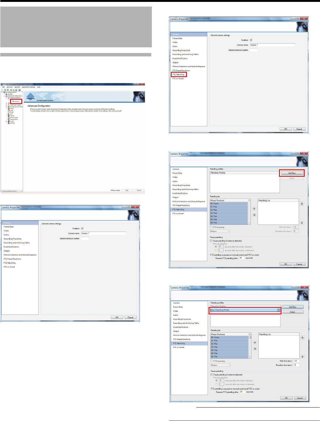
42
<Recorder Part> Applications
Auto PTZ Patrolling
(continued)
3 Double-click a camera name
The [Camera Properties] window appears.
4 Select [PTZ Patrolling]
5 Click [Add New]
6 Enter the PTZ patrol profile name.
Caution:
●The PTZ patrol profile name must be unique.
Defining a Preset PTZ
Position (continued)
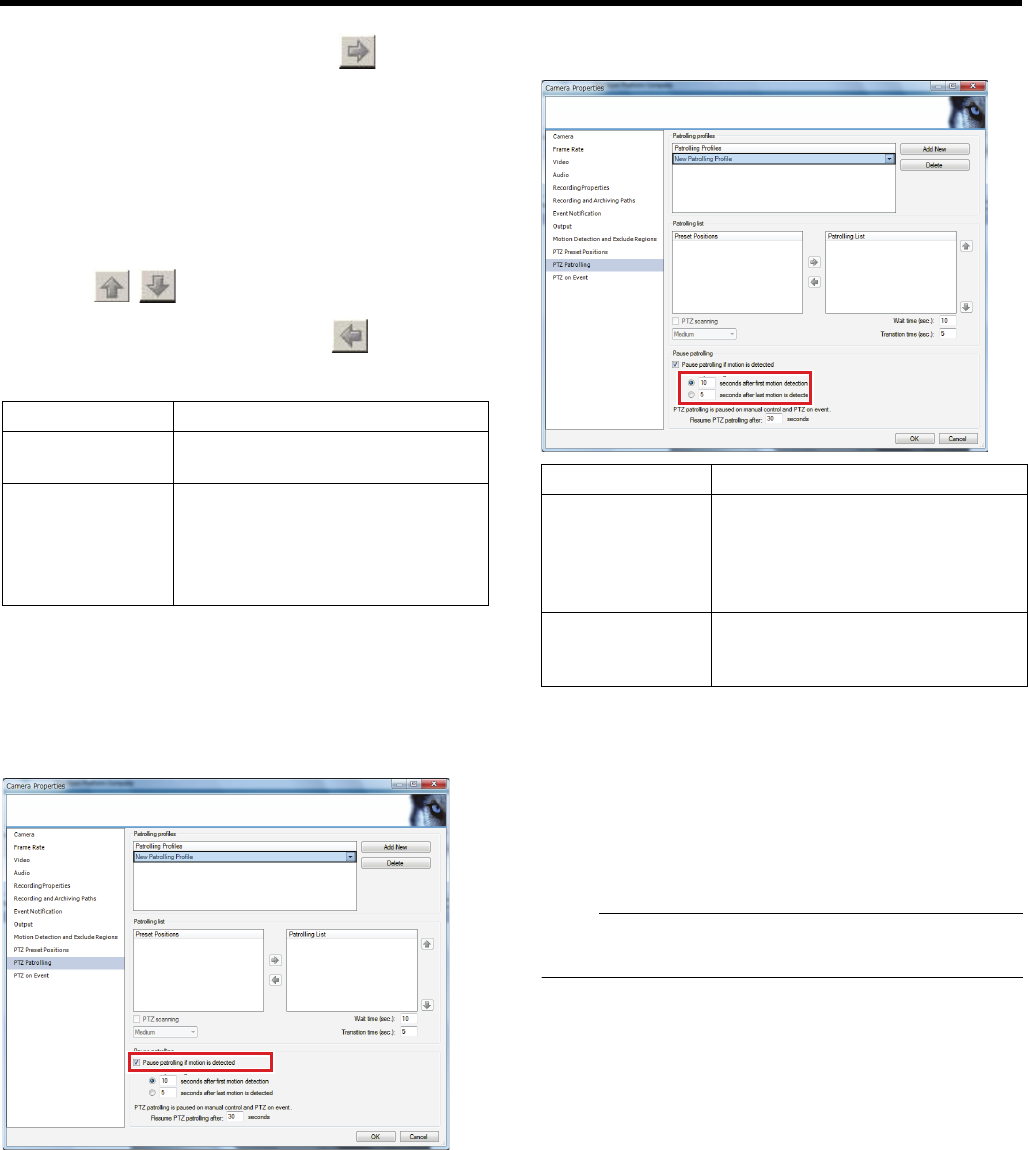
43
7 Select the preset positions you want to use in
the [Preset Positions], and click [ ]
Doing so copies the selected preset positions to the
[Patrolling list].
●A preset position can be used more than once in a
patrol scheme.
●The camera will move between the preset positions in
the sequence shown in the [Patrolling list], starting from
the top position.
●To change the sequence of preset positions in the
[Patrolling list] list, select a preset position name, and
click [ ][ ].
●To remove a preset position from the [Patrolling list],
select the preset position and click [ ].
8 Specify patrol timing
9 Click [OK]
䡵Pause patrolling when any motion is detected
1 Select the [Pause patrolling if motion is
detected] check box in the PTZ patrolling screen
2 Select the conditions for resuming PTZ
patrolling and specify units of seconds
䡵Resume patrolling paused manually or by any
event
Patrolling is paused at the time of manual PTZ operations or
occurrence of any event.
Time to resume paused patrolling is specified in [Resume
PTZ patrolling after:] in [Pause patrolling] in the PTZ
patrolling screen.
Note:
●The settings in this section are applied to all PTZ cameras
installed in the system.
䡵PTZ Scanning
For cameras that support PTZ scanning, enable this feature
by selecting the [PTZ scanning] check box. You may select a
PTZ scanning speed.
Item Description
Wait time (sec.) For specifying the down time (in
seconds) at each preset position.
Transition time
(sec.)
For specifying the time (in seconds)
that the PTZ camera takes to move
between the preset positions.
The motion detection is disabled
during the transition time.
Item Description
seconds after
first motion
detection
For resuming patrolling when a
specific time interval has lapsed after
the first detected motion, regardless
of whether any subsequent motion is
detected.
seconds after last
motion is
detected
For resuming patrolling when a
specific time interval has lapsed after
the last detected motion.
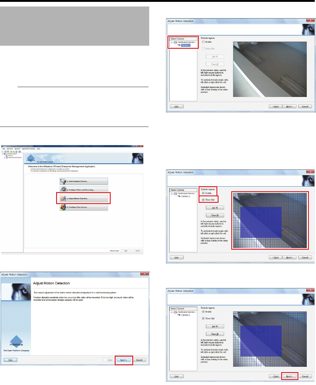
44
<Recorder Part> Applications
This section describes procedures to adjust the detection
sensitivity and range in accordance with conditions of
camera installation locations. Use the [Adjust Motion
Detection...] wizard for this setting.
Note:
●The setting method using the AAdjust Motion Detection...B
wizard will be explained. Settings can also be made by
double-clicking the camera name in AHardware DevicesB
of [Advanced Configuration] and displaying [Camera
Properties].
1 Click [Adjust Motion Detection...]
2 Click [Next]
3 Select a camera from [Select Camera]
4 Specify an area to be excluded
Select the [Enable] check box in [Exclude regions] and
drag the mouse on the preview screen to specify an area
to be excluded in motion detection. The area to be
excluded is indicated in blue.
●Select the [Show Grid] check box to show a grid in the
preview screen.
5 Click [Next]
The sensitivity setting screen appears.
Adjusting Motion Detection
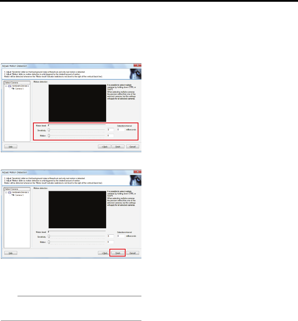
45
6 Select a camera from [Select Camera] and
specify noise sensitivity, detection interval and
motion sensitivity
●If you do not want to detect minute movements, move
the [Sensitivity] slider to the right.
●When any motion exceeds the sensitivity level defined
by the [Motion] slider, the [Motion level] indication turns
to red to indicate a motion is detected.
7 Click [Finish]
Return to the top window.
Next, specify the settings of starting recording by motion
detection (APage 55) or sending an e-mail (APage 62).
Note:
●After adjusting motion detection, specify the action when
detecting motion (starting recording (APage 55) or
sending an e-mail (APage 59)).
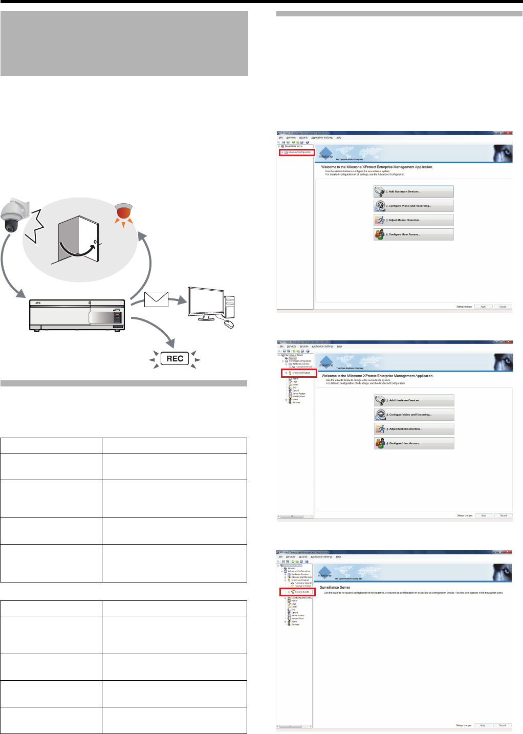
46
<Recorder Part> Applications
This system can perform particular actions such as recording
start and camera direction change, triggered by reception of
particular signals from cameras. A triggering input is called
an “event” and a behavior triggered by the event is called an
“action.”
With event and action settings, a certain action can be
activated when a certain event occurs by enabling the event
preset in a connected device in settings of this unit and
associating it with the action.
Types of Event and Action
Types of event and action are indicated below.
䡵Event types
䡵Action types
Events Configuration—Generic Event
When character strings received by this unit match the
predetermined conditions, a generic event is triggered. The
following is the procedure for setup on this unit including
communication data reception setting. For outgoing data
setting, settings of sender devices such as cameras are
necessary.
1 Click [+] in [Advanced Configuration]
2 Click [+] in [Events and Output]
3 Double-click [Generic Events]
Events and Actions
Event Description
Generic events
(right column)
Reception of particular character
strings (TCP/UDP format)
Input events
(APage 48)
●Detection of camera motion
●Input to cameras or input port
on the rear panel of this unit
Manual events
(APage 50)
Events to be generated manually
by using buttons, etc.
Timer events
(APage 51)
Events to stop action after a
specified time from occurrence of
any of the above events
Action Description
Movement to PTZ
camera preset
position (APage 52)
The PTZ camera is moved to a
preset position defined for each
event.
Image distribution
(Matrix) (APage 53)
Images are distributed to defined
recipient(s).
Record start
(APage 55)
Recording is started.
Output (APage 56) Sends a signal to the alarm
device, etc.
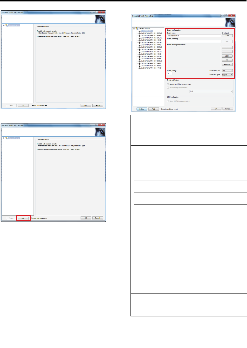
47
The [Generic Event Properties] window appears.
4 Click [Add]
The setting screen appears.
5 Specify the event name and contents
Note:
●The event name must be unique.
●The following characters cannot be used as part of the
event name and character strings.
< > & ' " \ / : * ? | [ ]
Item Description
Event
substring
For specifying an expression as a key word
for analysis of received character strings.
Click [Add] to add the expression you
entered to [Event message expression].
Event
message
expression
The added expression is displayed.
Furthermore, the following conditions are
edited.
() For putting related expressions as a single
entity. Expressions put in parenthesis are
processed in priority to other expressions.
AND Add this between expressions that must be
included.
OR Add this between expressions either of
which must be included.
Remove
For deleting expression to the left of the cursor.
Event
protocol
Select which protocol this unit uses to
receive on the detection of an event.
●Any: Both TCP and UDP data are
received and analysed.
●TCP: Only TCP data is received and
analysed.
●UDP: Only UDP data is received and
analysed.
Event rule
type
Set the rule for analysing the received data.
●Match: Only data which exactly matches
the message set in AEvent message
expressionB is analysed.
●Search: Data which includes the
message set in AEvent message
expressionB is analysed.
Event
priority
Each event is prioritized from A0B (lowest) to
A1000B (highest) to determine which event
will function when the received data
complies with more than on event rule.
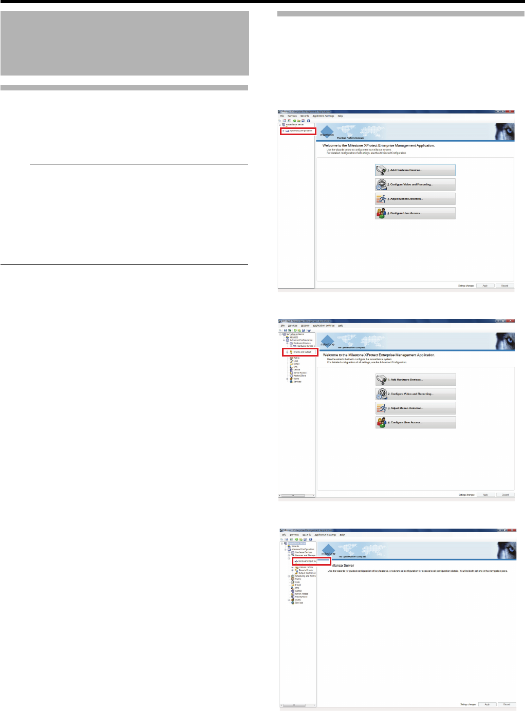
48
<Recorder Part> Applications
Events Configuration—Generic
Event (continued)
6 Click [OK]
The generic event has been configured.
Note:
●When you specify the event, specify the action for the
event. (A Page 52 to 56).
●When you select the setting to receive an e-mail when the
event you specified occurs, perform mail setup (APage
60 "Mail Setup for Management Application") and activate
the setting to receive an e-mail upon the occurrence of an
event. (APage 62 "Receive an e-mail upon the
occurrence of an event")
Event Configuration—Input Event
This section describes procedures to specify possible events
by signals from devices (hardware) connected to this unit
(including motion detection from cameras).
●You need to configure signals for each device in advance.
1 Click [+] in [Advanced Configuration]
2 Click [+] in [Events and Output]
3 Double-click [Hardware Input Events]
Events and Actions
(continued)
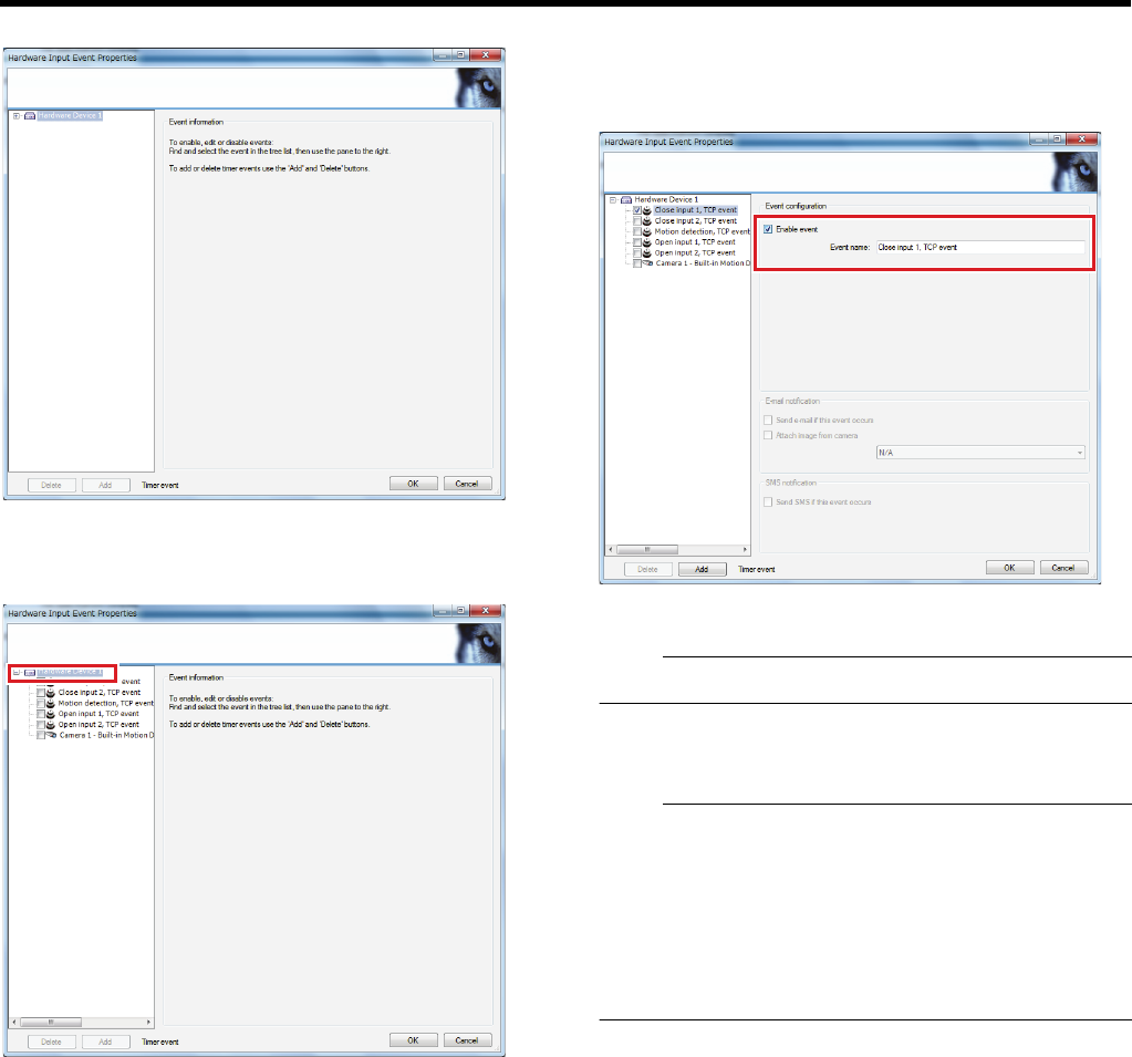
49
The [Hardware Input Event Properties] window appears.
4 Click [+] of the hardware to configure settings
A list of input events specified in the hardware is
displayed.
5 Click an input event to enable
The applicable input event setting screen appears.
6 Select the [Enable event] check box
●Then the check box in the input event list is selected
and the event is enabled.
●To change the event name, enter [Event name].
7
Repeat Steps 5 and 6 for each input event to enable
Note:
●Some input events may not be selected at the same time.
8 Click [OK]
The input event has been configured.
Note:
●When you specify the event, specify the action for the
event. (A Page 52 to 56).
●When you select the setting to receive an e-mail when the
event you specified occurs, perform mail setup (APage
60 "Mail Setup for Management Application") and activate
the setting to receive an e-mail upon the occurrence of an
event. (APage 62 "Receive an e-mail upon the
occurrence of an event")
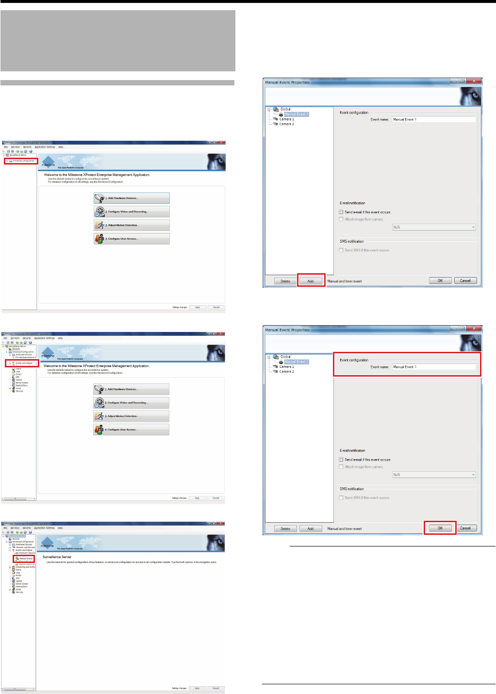
50
<Recorder Part> Applications
Event Configuration—Manual Event
If a manual event is set (created), any event can be produced
through operation on the Smart Client.
1 Click [+] in [Advanced Configuration]
2 Click [+] in [Events and Output]
3 Double-click [Manual Events]
The [Manual Event Properties] window appears.
4 Select the event setting target
●For setting all cameras: select [Global]
●For setting each camera individually: select the camera
name to set
5 Click [Add]
The event name setting screen appears.
6 Enter the event name and click [OK]
Note:
●If you change the camera name after setting the manual
events, manual events already registered may not work. In
this case, delete the manual events, then register them
again.
●When you specify the event, specify the action for the
event. (A Page 52 to 56).
●When you select the setting to receive an e-mail when the
event you specified occurs, perform mail setup (APage
60 "Mail Setup for Management Application") and activate
the setting to receive an e-mail upon the occurrence of an
event. (APage 62 "Receive an e-mail upon the
occurrence of an event")
Events and Actions
(continued)
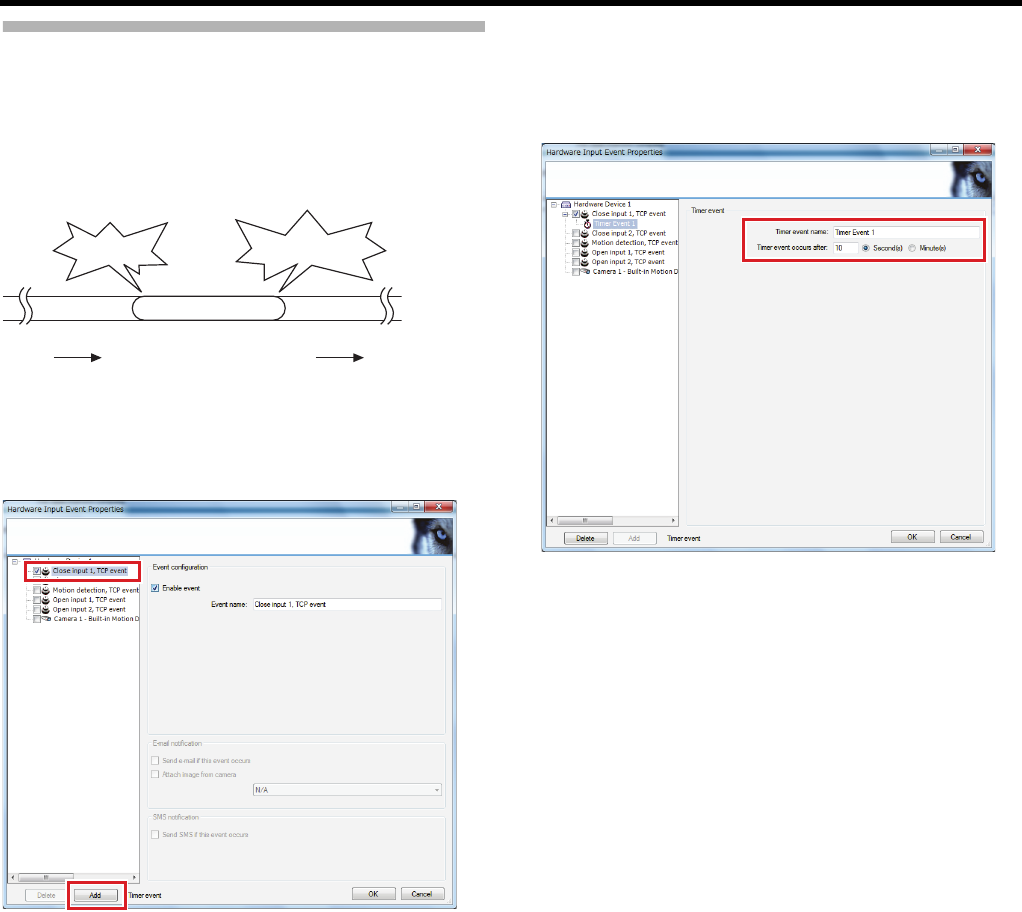
51
Events Configuration—Timer Event
This section describes procedures to specify an additional
event to end the action triggered by a generic event, input
event, or manual event.
After the time specified for the timer event from occurrence of
each event, the monitoring system returns to the normal
state.
1 Open the properties screen of each event
2 Select the event to set the timer event and click
[Add]
●To add a timer event for an input event
3 Enter a name and generation timing of the timer
event
●For generation timing of the timer event, specify the
time elapsed from occurrence of the event you want to
end.
4 Click [OK]
The timer event has been configured.
Event Timer event
Record
Stopped state Stopped state
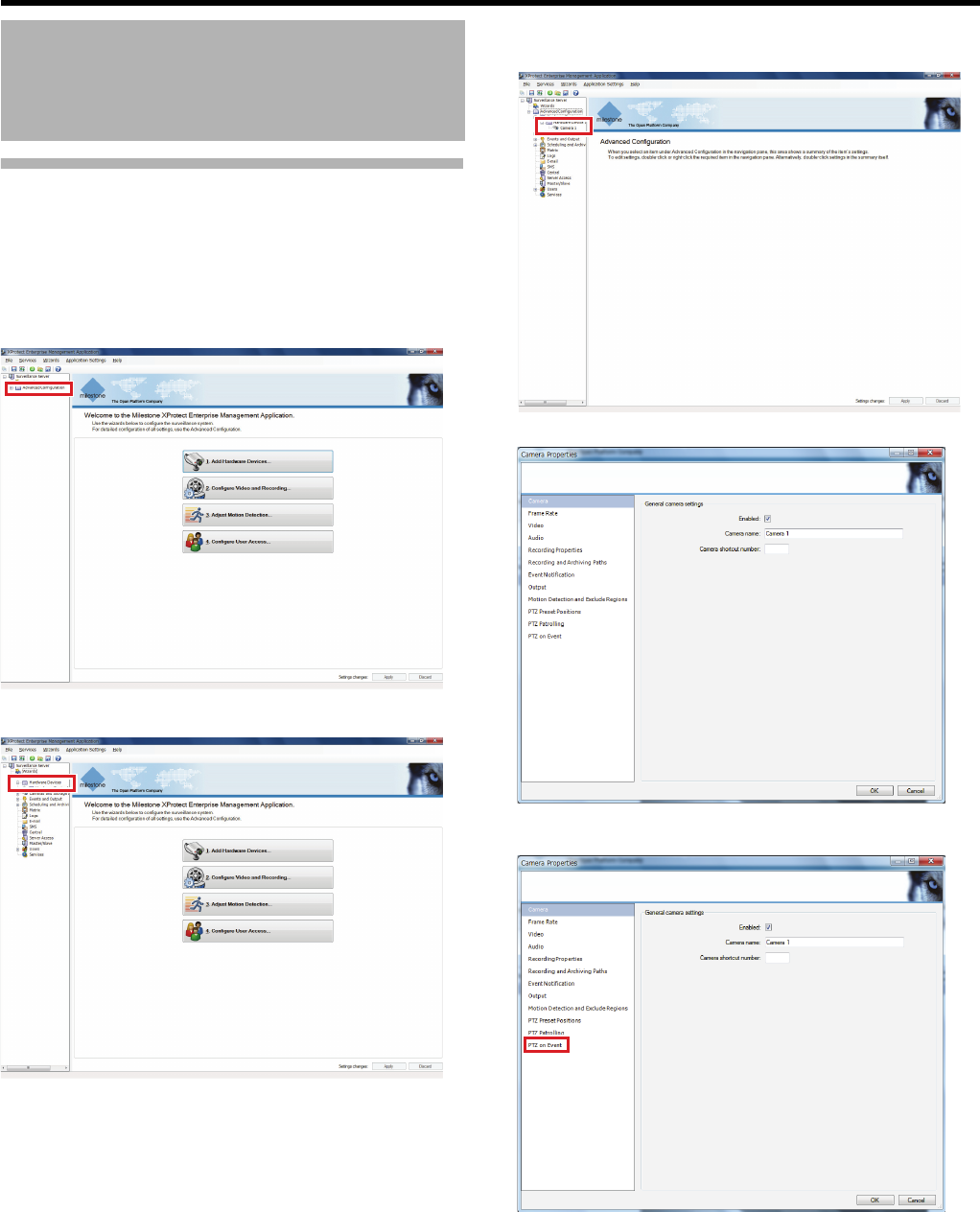
52
<Recorder Part> Applications
Action Setup—Moving the PTZ
Camera Preset Position
When the event occurs, the PTZ camera is directed to the
defined preset position. (APage 39 "Defining a Preset PTZ
Position")
1 Click [+] in [Advanced Configuration]
2 Click [+] in [Hardware Devices]
3 Click the [+] of [Hardware Device] of the camera
to set and double-click the camera name
The [Camera Properties] window appears.
4 Select [PTZ on event]
Events and Actions
(continued)
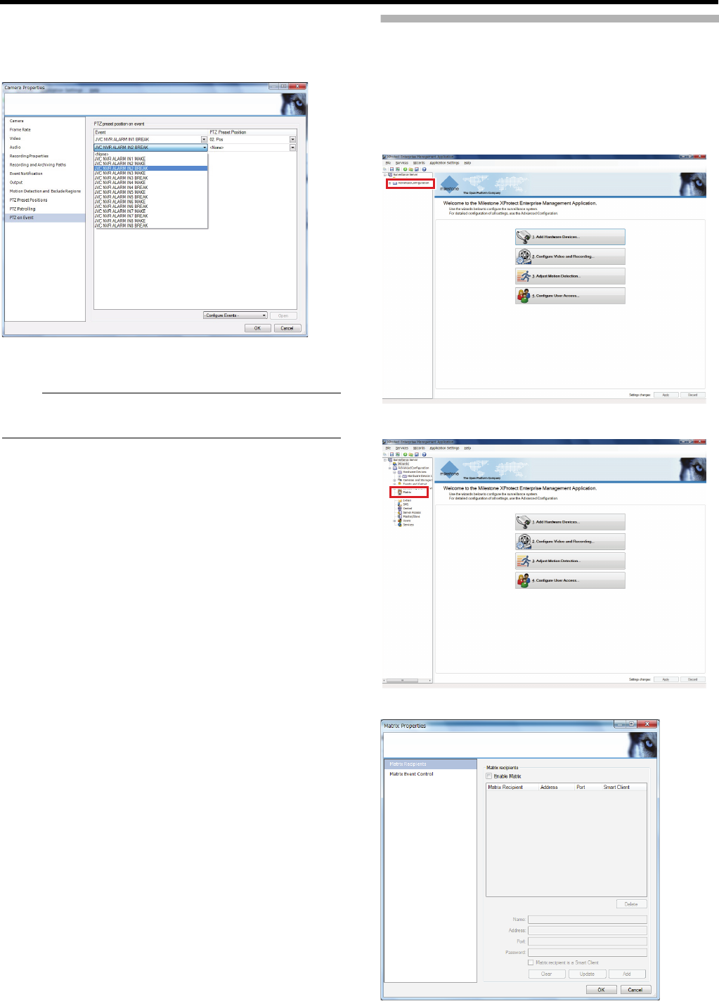
53
5 Specify a combination of an event and a preset
position
●The same event cannot be coupled with more than one
preset position.
6 Click [OK]
The preset position movement by event has been set.
Note:
●To remove the association between a preset position and
an event, select [None] for the event and preset position.
Action Setup—Distributing Camera
Images (Matrix)
Live images can be distributed to specified computer(s)
(recipient(s)) when any event occurs. You can view the
distributed images on a computer with the Smart Client.
1 Click [+] in [Advanced Configuration]
2 Double-click [Matrix]
The [Matrix Properties] window appears.
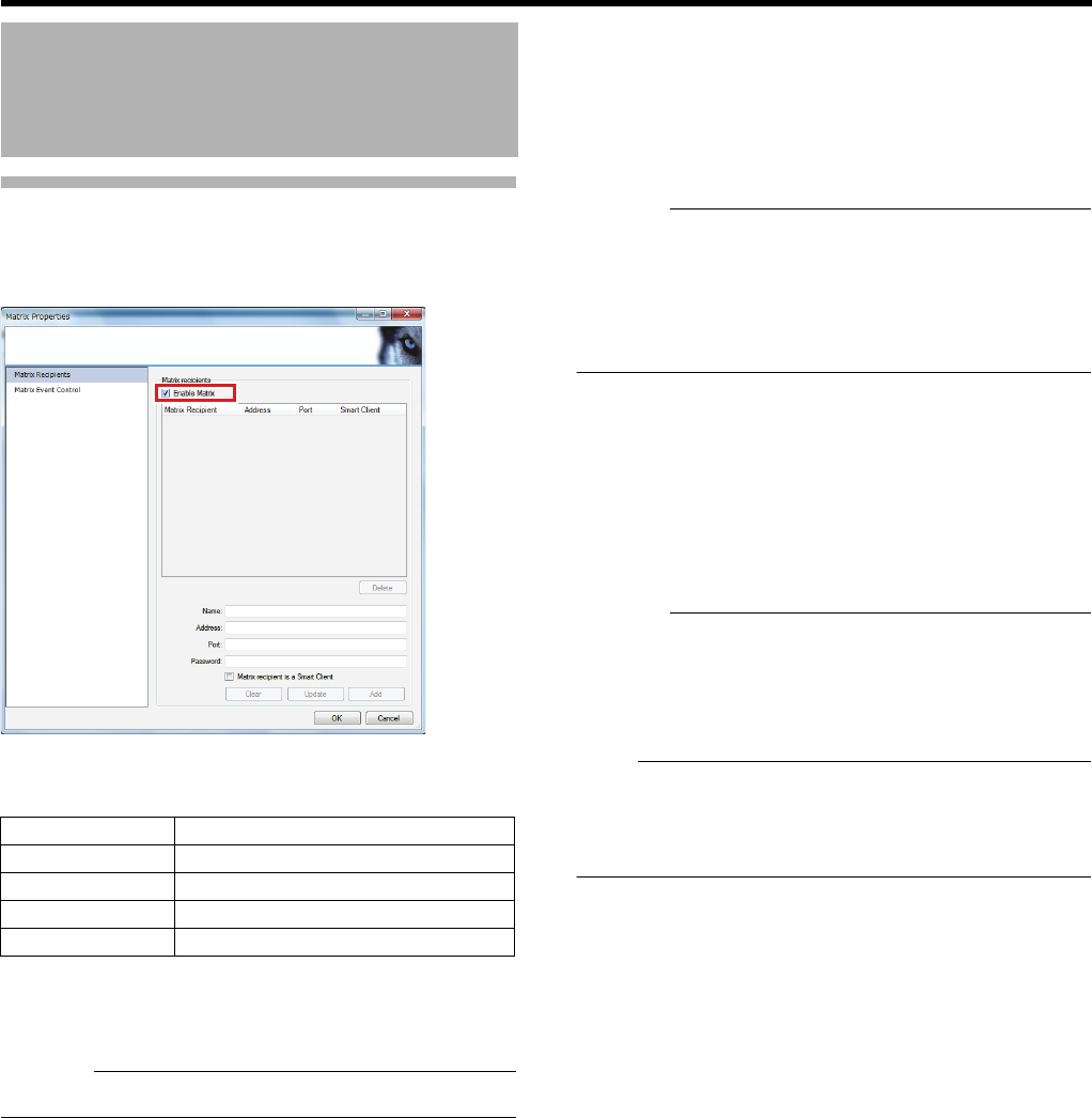
54
<Recorder Part> Applications
Action Setup—Distributing Camera
Images (Matrix) (continued)
3 Select the [Enable Matrix] check box
4 Enter recipient properties and click [Add]
Specify the information in the following items.
●Click [Clear] to cancel all entries.
●If the Smart Client is installed in the recipient’s
terminal, select the [Matrix recipient is a Smart Client]
check box.
Caution:
●Do not set multiple Matrix recipients to the same port.
5 Click [Matrix Event Control]
A list of events for each recipient is displayed.
6 Select an event for each recipient
When relating Matrix to events, right-click the event name
and select a method from [Connect], [Disconnect, then
connect], or [Disconnect].
Caution:
●When multiple Matrix windows are set by the recipient,
select [Connect]. If [Disconnect] or [Disconnect, then
connect] is selected, the connection information of the
Matrix window and the camera will be erased and images
will not displayed in windows with [Window Index]
(APage 179) set to [2] or higher.
7 Select a camera to distribute live images to
computer(s).
Right-click the action ([Connect], [Disconnect, then
connect], or [Disconnect]) selected in step 6, then specify
settings of the camera.
8 Click [OK]
The image distribution by event has been set.
Caution:
●If Matrix images are not displayed, select [Block, and
reconnect] and reconnect. If images are not displayed
even when connected, check the Matrix settings such as
the recipient's port number, the event settings, and
whether or not an event has occurred.
Note:
●You need to perform settings of Smart Client from the
recipient to distribute images. See ASetting the Matrix
Display AreaB (A Page 179) to specify the display
position of the images.
Events and Actions
(continued)
Item Description
Name Recipient’s name
Address Recipient’s IP address
Port Recipient’s port number
Password Recipient’s password
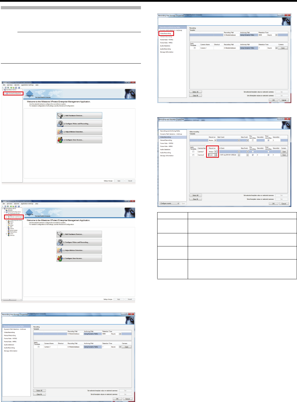
55
Action Setup—Starting Recording
Recording is started upon the occurrence of any event.
Note:
●You can perform the same settings below by opening the
properties of each camera from [Hardware device] in
[Advanced Configuration]. (APage 95 "Recording
Properties")
1 Click [+] in [Advanced Configuration]
2 Double-click [Cameras and Storage Information]
The [Recording and Storage Properties] window appears.
3 Select [Video Recording]
4 Select an event that starts recording
●Select the [Apply Template] check box and click [Apply]
to apply the settings selected in [Template - >] in the
upper part to all selected cameras.
Item Description
Always For recording images always.
(Recording is not triggered by an event.)
Motion
Detection
For starting recording by motion detection.
Event For starting recording by any event other than
motion detection.
Event and
motion
detection
For starting recording upon the occurrence of
an event including motion detection.
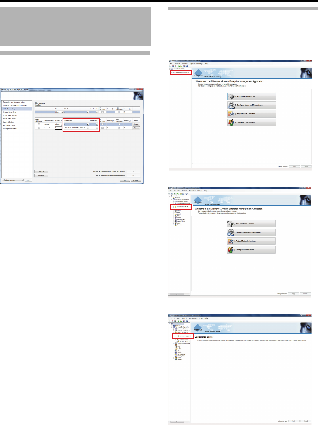
56
<Recorder Part> Applications
Action Setup—Starting Recording
(continued)
5 Select the event to start/stop recording
●If [Event] or [Event and motion detection] has been
selected in step 4, select [Start Event] and [Stop
Event].
6 Click [OK]
The recording start by event has been set.
Action Setup—Output
This section describes procedures to set an action to control
external devices such as lights, sirens and door opening/
shutting system connected with this unit.
1 Click [+] in [Advanced Configuration]
2 Click [+] in [Events and Output]
3 Double-click [Hardware Output]
Events and Actions
(continued)
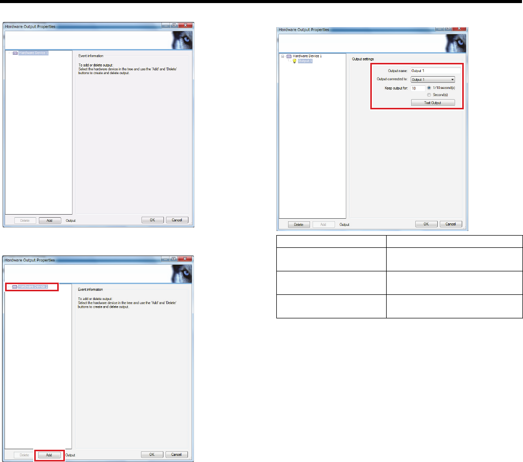
57
The [Hardware Output Properties] window appears.
4 Select hardware to configure and click [Add]
5 Specify essential properties
●Some output devices may have limitations on the
number of characters and format for the name.
●Some output devices may have relatively short and/or
limited continuous output time.
●Click [Test Output] to test the output.
6 Click [OK]
The output by event has been set.
Item Description
Output name For specifying a name for the
output.
Output connected to For specifying an output
destination device.
Keep output for For specifying the time of
output.
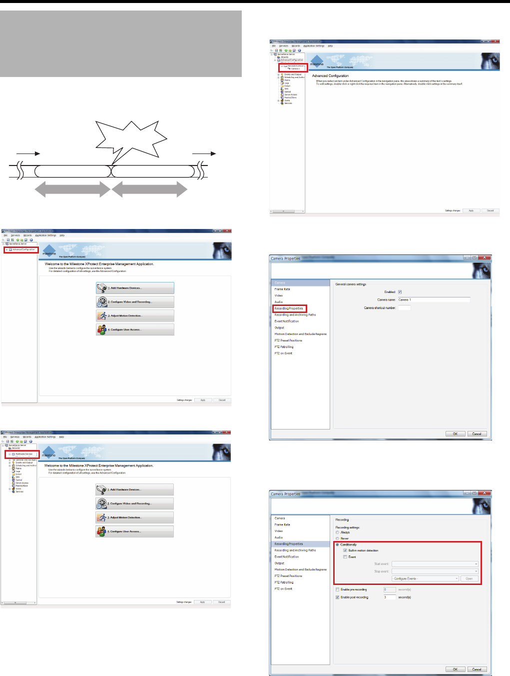
58
<Recorder Part> Applications
Images before/after the occurrence of an event or motion can
be recorded.
1 Click [+] in [Advanced Configuration]
2 Click [+] in [Hardware Devices]
3 Click the [+] of [Hardware Device] of the camera
to set and double-click the camera name
The [Camera Properties] window appears.
4 Select [Recording Properties]
5 Set [Recording Settings] to [Conditionally] and
set the type of condition (motion detection or
event)
Recording Images Before/
After Occurrence of Event
or Motion
Stopped state
Motion/Event
Stopped state
Preceding
seconds Record Following
seconds Record
Set time Set time
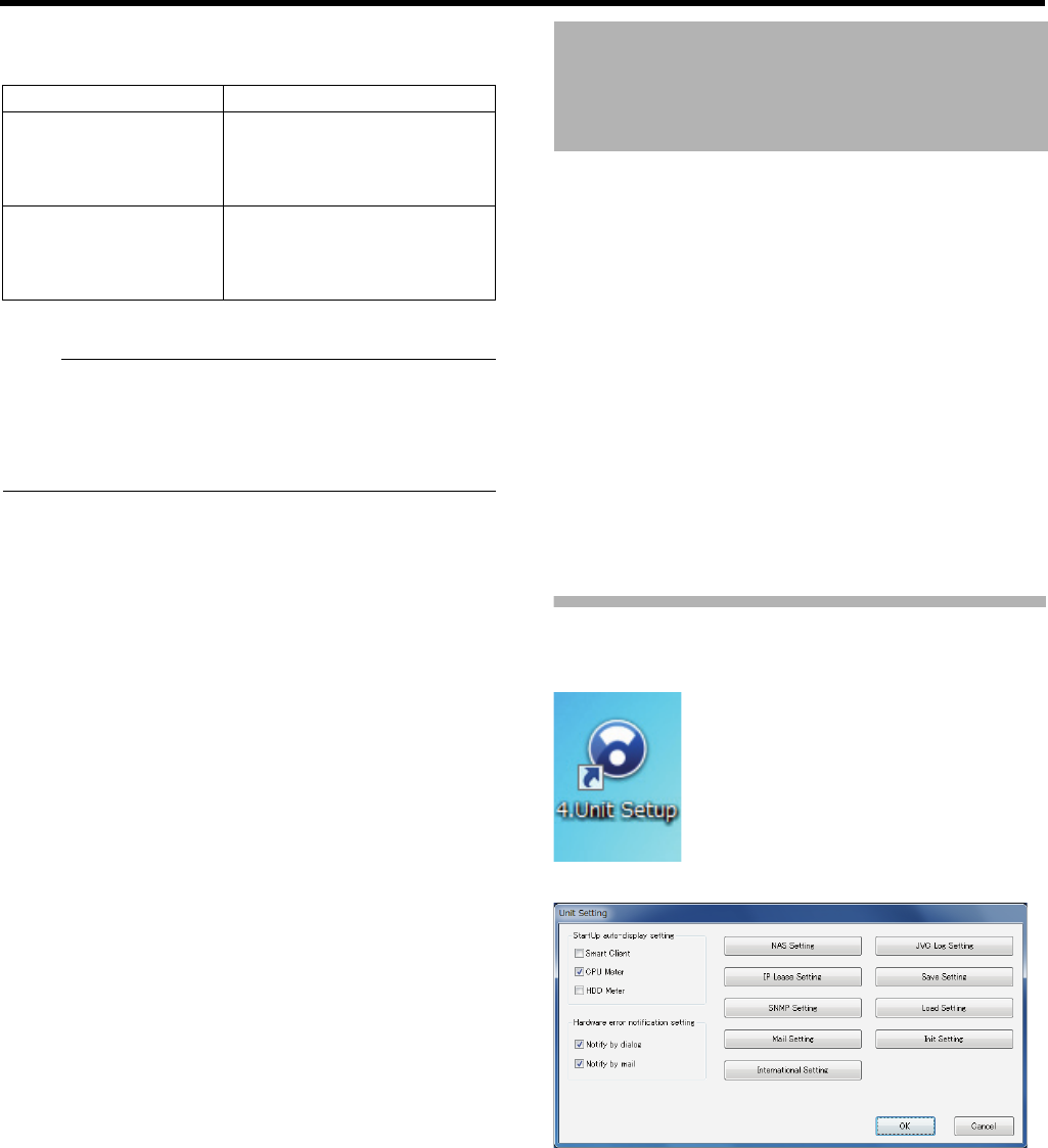
59
6 Specify units of seconds to record before/after
the occurrence
7 Click [OK]
Note:
●A group of images before/after any motion/event is called
a sequence.
●
For how to use a sequence, refer to "Searching from the
Image List" (
A
Page 149) "Searching for Recorded
Images" (
A
Page 151).
Any abnormality in this unit or monitoring system can be
notified through e-mail.
Use 2 windows to configure mail settings.
䢇Notifications related to hardware
●Formatting of built-in HDD
●Formatting of external HDD
●Deterioration of built-in HDD reliability
●RAID abnormality (if applicable)
●Detection of heat radiation stoppage
䢇Notifications from Management Application or
Smart Client
●Motion detection
●Event occurrence
●Disconnection and restoration of communication with
cameras
●Archive error occurrence
Mail Settings of Unit Setting
1 Double-click [4. Unit Setup] on the desktop
The [Unit Setting] window appears.
Item Description
Enable pre-recording
To record images before any
motion/event, select this check
box and enter units of seconds
for recording.
Enable post-recording
To record images after any
motion/event, select this check
box and enter units of seconds
for recording.
Configuring Mail Settings
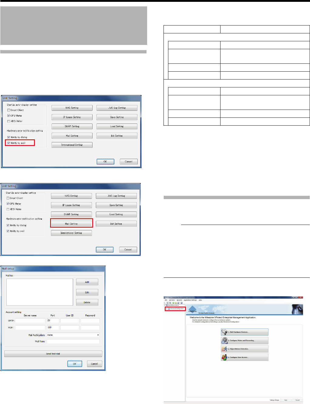
60
<Recorder Part> Applications
Mail Settings of Unit Setting
(continued)
2 Select the [Notify by mail] check box in
[Hardware error notification setting]
3 Click [Mail Setting]
The [Mail setup] window appears.
4 Specify the recipient address(es)
●Add an address that is not listed, click [Add] and enter
the address.
●To change e-mail address(es), select any address to
change from the list and click [Edit].
●To delete e-mail address(es), select any address to
delete from the list and click [Delete].
5 Configuring the outgoing and incoming mail
servers
6 Specify the authentication method for mail
delivery
●For queries on the settings, consult your system
administrator.
7 Enter the mail sender’s address
●Click [Send test mail] to send a test mail.
8 Click [OK]
Mail Setup for Management
Application
Note:
●To receive a notification upon the occurrence of an event,
you need to enable mail notification in the settings of the
event you want to receive notifications for.
●The email notification period can also be specified in
[Scheduling and Archiving] in [Advanced Configuration]
(APage 121)
●This unit does not support notifications by SMS.
1 Click [+] in [Advanced Configuration]
Configuring Mail Settings
(continued) Item Description
SMTP (outgoing mail server)
Server name For specifying the server name.
Port For specifying the port number.
(Default value: 25)
User ID For specifying the user ID.
Password For specifying the password.
POP (incoming mail server)
Server name For specifying the server name.
Port For specifying the port number.
(Default value: 110)
User ID For specifying the user ID.
Password For specifying the password.
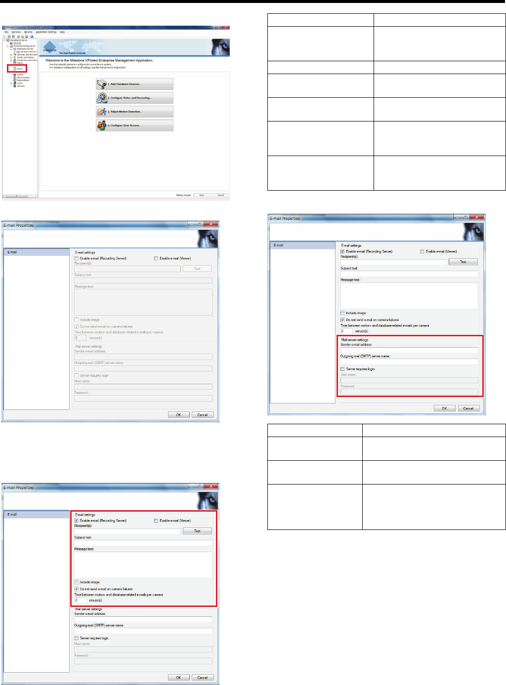
61
2 Double-click [E-mail]
The [E-mail Properties] window appears.
3 Select the [Enable e-mail (Recording Server)]/
[Enable e-mail (Viewer)] check box and
configure settings of recipient(s) and mail
content
4 Specify the mail sender
5 Click [OK]
Item Description
Recipient(s) For specifying the mail
address(es) to receive the
notification e-mail
Subject text For specifying the mail title.
Message text For specifying the message
body.
Include Image Select this check box to attach
images to the notification mail.
Do not send e-mail on
camera failures
Select this check box to send
no mail when the camera is
faulty.
Time between motion-
and database-related
e-mails per camera
For specifying the time interval
(minutes) for sending each mail
notification.
Item Description
Sender e-mail
address
For specifying the e-mail address
to send notifications from.
Outgoing mail
(SMTP) server name
For specifying the server name.
Server requires
login
Select this check box to specify a
user name and password to
require login to the server for
sending mails.
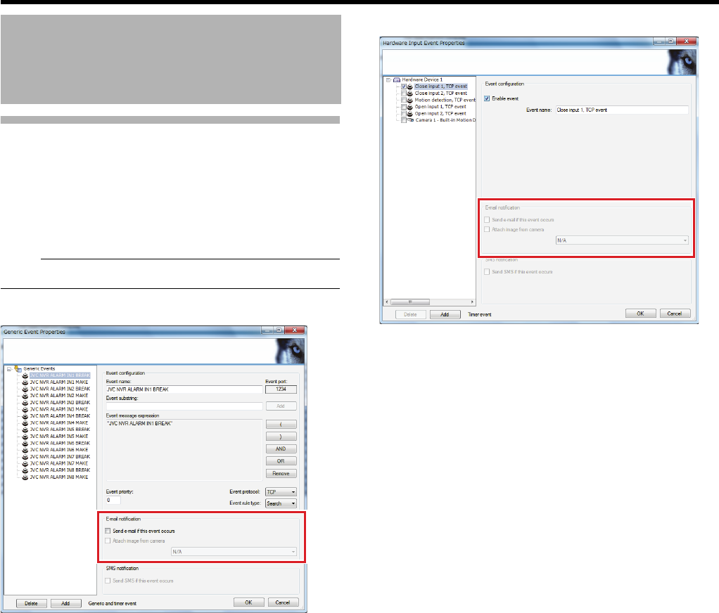
62
<Recorder Part> Applications
Mail Setup for Management
Application
(continued)
䡵Receive an e-mail upon the occurrence of an
event
Select the e-mail notification setting check box in each event
setting screen.
Note:
●This unit does not support notifications by SMS.
䢇When a generic event occurs
1 Click [+] in [Advanced Configuration]
2 Click [+] in [Events and Output]
3 Click [+] in [Generic Events]
4 Double-click any event name you want to set
The [Generic Event Properties] window appears.
5 Select the [Send e-mail if this event occurs]
check box
●To attach images to notification mails, select [Attach
image from camera] and select an image source.
䢇When an input event occurs/a motion is detected
1 Click [+] in [Advanced Configuration]
2 Click [+] in [Events and Output]
3 Double-click [Hardware Input Events]
4 Double-click any event name you want to set
The [Hardware Input Event Properties] window appears.
5 Select the [Send e-mail if this event occurs]
check box
●To attach images to notification mails, select [Attach
image from camera] and select an image source.
Configuring Mail Settings
(continued)
63
䢇When a manual event occurs
1 Click [+] in [Advanced Configuration]
2 Click [+] in [Events and Output]
3 Click [+] in [Manual Events]
4 Double-click any event name you want to set
The [Manual Event Properties] window property appears.
5 Select the [Send e-mail if this event occurs]
check box
●To attach images to notification mails, select the
[Attach image from camera] and select an image
source.
You can use more than one NVR to build a large-scale
system with a large number of cameras. In this case, one
NVR is used as a master and other NVRs are registered with
the master NVR as slaves.
●Up to seven Slave NVR can be registered for a single
Master NVR.
●Up to 128 cameras can be controlled by a single master/
slave system.
AMaster NVR
BSwitching hub (LAN1 of the master NVR)
CSwitching hub (LAN2 of the master NVR/LAN2 of the
slave NVR)
DSlave NVR
ESwitching hub (LAN1 of the slave NVR)
Caution:
●If you set this unit as a slave, connect only one master
NVR. Connecting more than one master NVR may cause
this unit to malfunction.
●The version of all NVR units in a master/slave system
must be set the same.
●The NVR unit operating as the master server cannot be
used as a slave server for another NVR unit.
●When operating as the master server, the recording
display performance may drop.
Note:
●VR-X3200U and VR-X1600U may be mixed in a master/
slave system.
●If you change the identity (host name) of an NVR within
the network, each NVR will become easier to identify.
Select [Advanced Configuration], [Server Access], [Server
name] in this order to specify the host name.
(APage 111)
Using More Than One NVR
64
<Recorder Part> Applications
Specifying a Master NVR
Configure settings from the NVR to be used as the master.
1 Click [+] in [Advanced Configuration]
2 Double-click [Master/Slave]
The master/slave setting screen appears.
3 Select the [Enable as master server] check box
and click [OK]
Using More Than One NVR
(continued)
65
Registering a Slave NVR
Configure settings from the NVR to be used as the master.
1 Click [+] in [Advanced Configuration]
2 Double-click [Master/Slave]
The master/slave setting screen appears.
●Ensure that the [Enable as master server] check box is
selected.
3 Click [Add]
The slave server setting screen appears.
4 Specify the address and port number of the
slave server
5 Click [OK]
The NVR you just configured is registered as a slave.
66
<Recorder Part> Applications
This section describes procedures to register user(s) of
Smart Client and configure the rights of each user.
Adding a User
The following is the procedure to configure the settings with
the [Configure User Access...] wizard. You may also
configure the settings from [Users] in [Advanced
Configuration].
1 Click [Configure User Access...]
2 Click [Next]
3 Configure server access settings
4 Click [Next]
The user type (basic user or Windows user) setting
screen appears.
Set the standard user which uses the viewer (Smart
Client).
5 Enter the user name and password and click [Add
Basic User]
The user is registered as a new user.
Configuring Smart Client
User Settings
Item Description
Server name For specifying the name to identify this unit
in the network.
Local port For specifying the port number to use for
the server.
Character
encode
(language)
Make sure to set to [Western European
(ISO) (iso-8859-1)].
Enable
internet
access
Select this check box when connecting a
surveillance computer to the unit through
the internet.
When selected, specify the global IP
address of the router or firewall in the
internet access field, and the port number
for access of the surveillance computer in
the internet port field.
67
6 Click [Next]
The access overview screen appears. Check the added
user’s right to access the cameras.
7 Click [Finish]
The user has been configured.
Limiting the Rights of Each User
You can limit allowed operations of cameras and the viewer
for each user.
1 Click [+] in [Advanced Configuration]
2 Click [+] in [Users] and double-click a user name
to configure settings for
The user property screen appears.
68
<Recorder Part> Applications
Limiting the Rights of Each User
(continued)
3 Click [Generic Access Properties]
The screen for setting the viewer access authorizations
appears.
4 Deselect functions you want to limit the use of
(prohibit)
5 Click [Camera Access]
The screen for setting the camera access authorizations
appears.
6 Deselect functions you want to limit the use of
(prohibit)
●To prohibit all functions, deselect the [Access] check
box to the left of the camera name.
7 Click [OK]
The settings have been changed.
Adding a User Group
When registering more than one user with the same rights,
rather than set each user separately, it is more convenient to
create a group.
1 Click [+] in [Advanced Configuration]
Configuring Smart Client
User Settings (continued)
69
2
Right-click [Users], then click [Add New User Group]
3 Enter the group name, and click [OK]
The group properties window appears.
4 Set the group access rights, then click [OK]
A new user group has been added.
●For access rights settings, see steps 3 to 6 in "Limiting
the Rights of Each User" (APage 67).
Next, add a user to the created user group.
5 Right-click the user group and click [Add New
Basic User] or [Add New Windows User]
6 Set the user name and password, then click [OK]
●When [Add New Basic User] has been selected
● When [Add New Windows User] has been selected
The user has been registered to the group.
70
<Recorder Part> Applications
You can set a login password so only the administrator can
operate Management Application.
1 Click [+] in [Advanced Configuration]
2 Click [+] in [Users]
3 Double-click [Administrator]
The [Administration Protection Properties] screen
appears.
4 Select the [Enable] check box for
[Administration protection]
5 Enter a password, then click [OK]
The activation password for Management Application is
set, and the password will be required the next time
Management Application is started.
Configuring the Startup
Password of Management
Application
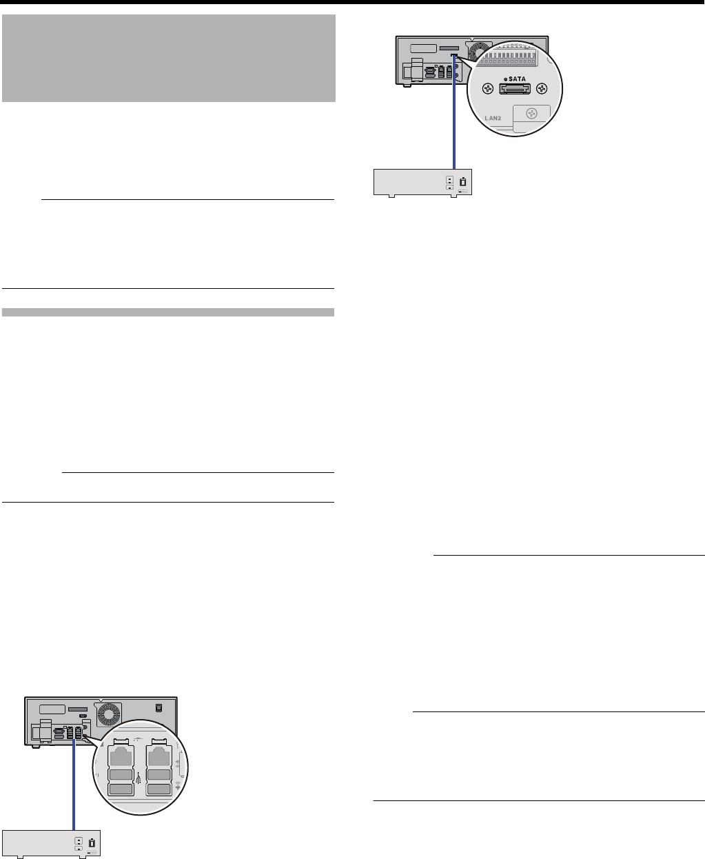
71
The SERIAL terminal and eSATA terminal on the rear panel
of this unit can be used for additional HDD(s).
Also, up to 3 built-in HDDs can be added to increase the
capacity up to 4TB.
Note:
●For details of compatible additional HDD, consult your
nearest JVC KENWOOD dealer or service center. You
can also check on our website.
●For addition of built-in HDD(s), consult an authorized
dealer or a JVC KENWOOD service center.
Connecting an External HDD
This section describes procedures to connect a drive to the
SERIAL terminal or eSATA terminal on the rear panel of this
unit.
1 Press and hold down the [OPERATE] button for
about 2 seconds to shut down the system
2 Turn off the power switch on the rear panel
Caution:
●Make sure to turn off the power switch.
3 Connect additional HDD(s) to the SERIAL
terminal and/or eSATA terminal on the rear panel
and switch the power of the additional HDD(s)
on
●Make sure to switch on the power of the additional
HDD(s) before switching on the power of this unit.
Otherwise, the additional HDD(s) may not be
recognized.
䢇SERIAL terminal
䢇eSATA terminal
䡵When an External HDD has been added
When an external HDD has been added, follow the steps
below to format it.
1 Turn on this unit
2 Click the [Start] button on the desktop
3 Right-click [Computer], then select [Computer
Control]
The [Computer Control] screen appears.
4 Select [Disk Control]
5 Right-click the added HDD and select [New
Simple Volume]
The wizard will start up.
6 Follow the wizard to set drive partitions, etc.
Once the wizard is complete, formatting will start.
Once the formatting is complete, the drive name is
displayed and the external HDD is ready to use.
Caution:
●When an additional HDD is connected, several seconds of
the recorded image may be lost during archiving.
●Note that playing back video recorded in an external HDD
simultaneously on this unit and multiple clients may cause
delay in the playback of video images and audio sound.
This is not a malfunction and there is no problem with the
recorded images. Normal playback will be restored when
simultaneous playback stops or when the number of
devices playing back at the same time decreases.
Note:
●It is recommended that a UPS be used to ensure stable
operation of the system. (APage 125 "Using UPS")
●You are unable to view recorded images on the computer
by disconnecting the external HDD from this unit and
connecting it to the computer.
Adding an HDD
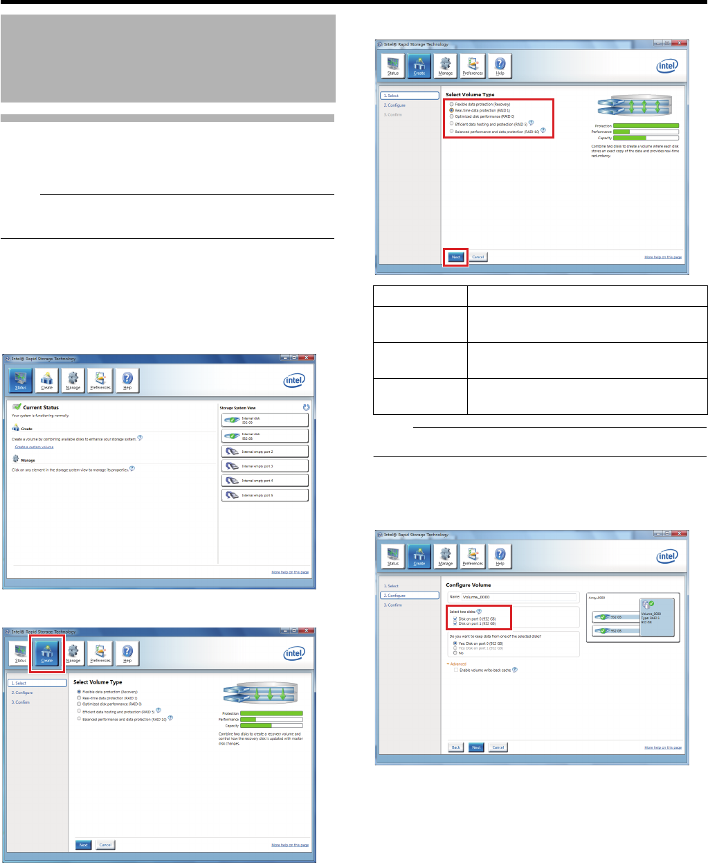
72
<Recorder Part> Applications
Building a RAID Configuration
You can add built-in HDD(s) to build a RAID configuration.
This unit is compliant to RAID 1/5/10.
Note:
●For addition of built-in HDD(s), consult an authorized
dealer or a JVC KENWOOD service center.
1 Turn on this unit
2 Click the [Start] button on the desktop, then
click [All Programs] > [Intel] > [Intel(R) Rapid
Storage Technology]
The Intel(R) Rapid Storage Technology is launched.
3 Click [Create]
4 Select the volume, then click [Next]
Note:
●Build RAID1, RAID5, or RAID10.
5 Select the HDDs to build the RAID configuration
Select [port 0] and the required additional HDDs ([port 1]
to [port 3]).
Adding an HDD (continued)
Item Description
RAID0/RAID1 Add one HDD, and build using a total of
two HDDs.
RAID5 Add two HDDs, and build using a total of
three HDDs.
RAID10 Add three HDDs, and build using a total of
four HDDs.
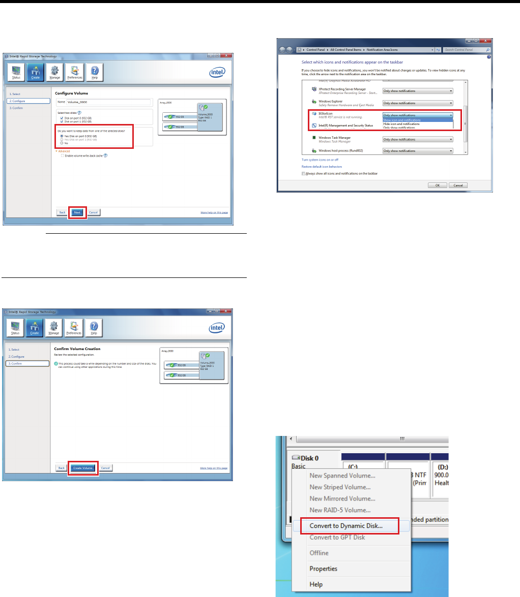
73
6 Select [Yes: Disk on port 0] for [Do you want to
keep data from one of selected disk?], then click
[Next]
Caution:
●Keep [Enable volume write-back cache] in the advanced
settings disabled; otherwise, performance of the unit may
drop.
7 Click [Create Volume]
8 Click [▲] on the taskbar at the lower right corner
of the screen, and click [Customize]
[Selection of icon and notice to display on the taskbar]
starts up.
9 Change the setting of [IAStorIcon] to [Display
Icon and Notice]
10 Click [OK]
䡵Creating a simple volume
After building a RAID5 or RAID10 configuration, follow the
procedure below to use free space of the HDD effectively.
1 Click the [Start] button on the desktop, followed
by clicking [Control Panel]
The control panel opens up.
2 Click [System and Security]
The [System and Security] window appears.
3 Click [Create and format hard disk partitions] on
[Administrative Tools]
The [Disk Management] window appears.
4 Right-click [Disk 0], and select [Convert to
Dynamic Disk....]
The [Convert to Dynamic Disk] window appears.
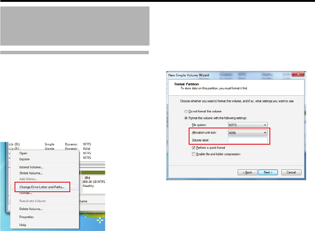
74
<Recorder Part> Applications
Building a RAID Configuration
(continued)
5 Confirm that the [Disk 0] check box is selected,
and click [OK]
The [Disks to Convert] window appears.
6 Click [Convert], and click [Yes] on the
confirmation screen
7 Right-click [(E:)], and select [Change Drive
Letter and Paths...]
The [Change Drive Letter and Paths for E: ()] window
appears.
8 Confirm that [(E:)] is selected, and click
[Remove]
The confirmation screen appears.
9 Click [Yes]
[WARNING:HDD(E) Deleted] appears and the WARNING
indicator lights up.
10 Click [OK] to close the window
11 Right-click [Unallocated], and select [New
Simple Volume]
The [New Simple Volume Wizard] window appears.
12 Click [Next]
On the [Specify Volume Size] window, click [Next] to
proceed to the next.
On the [Assign Drive Letter or Path] window, click [Next] to
proceed to the next.
The [Format Partition] window appears.
13 Select [4096] for [Allocation unit size] and
delete the characters in [Volume label]
14 Click [Next]
The confirmation screen appears.
15 Click [Finish]
16 Select [Shutdown] > [Restart] from the [Start]
menu to restart the unit
Adding an HDD (continued)
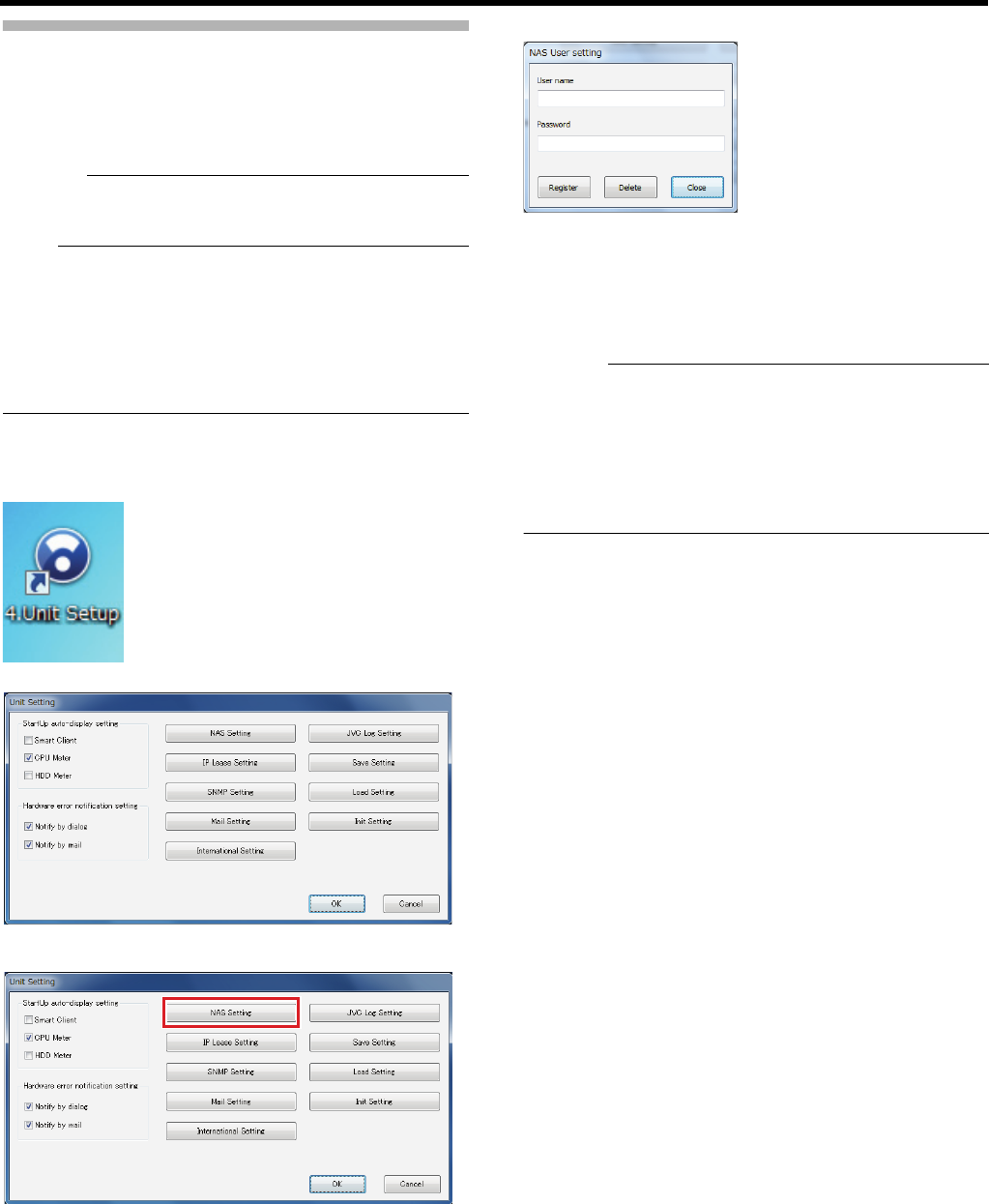
75
Using NAS
NAS (Network Attached Storage) is a dedicated file server
that is connected to the LAN1 network.
In the case of NVR, you can specify NAS connected to the
camera network (LAN1) as a drive for archiving data.
Caution:
●When NAS is used, the recording frame rate will decrease
depending on the NAS performance.
Note:
●Follow the NAS [Instruction Manual] for settings on NAS.
This may take a while depending on the format and RAID
settings, etc. For further details, please contact the NAS
manufacturer.
●For details on NAS you can connect to this unit, consult
your nearest JVC KENWOOD dealer. You can also check
on our website.
䡵Connecting to NAS
1 Double-click [4. Unit Setup] on the desktop
The [Unit Setting] window appears.
2 Click [NAS Setting]
The NAS connection user setting screen appears.
3 Enter the [User name] and [Password] that are
configured on the NAS device for access to NAS
in [NAS User setting], and click [Register]
A Windows user is created on the this unit with the
entered user name and password.
Caution:
●Specify a name different from the host name defined in
"Connect This Unit to a Network" (APage 31) as the user
name for NAS setting.
●If other Windows users have been created outside [NAS
User setting], those users will be erased. (Basic users
created using Management Application will not be
deleted.)
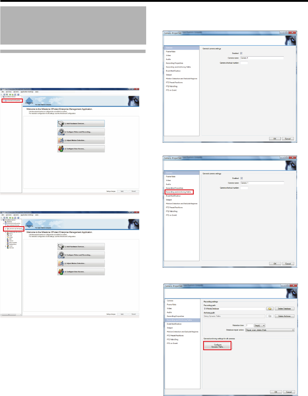
76
<Recorder Part> Applications
Using NAS (continued)
䡵Specify NAS as the archiving destination
1 Click [+] in [Advanced Configuration]
2 Click [+] in [Cameras and Storage Information]
3 Double-click a camera name to configure
settings for
The [Camera Properties] window appears.
4 Select [Recording and Archiving Paths]
5 Click [Configure Dynamic Paths…]
Adding an HDD (continued)
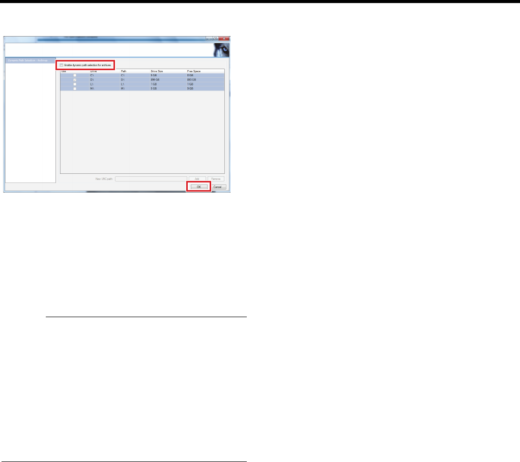
77
6
Deselect the [Enable dynamic path selection for
archives] check box, then click [OK]
You are returned to the [Camera Properties] screen.
7
Specify the path to the NAS drive in [Archiving path]
●The path can be set by specifying through the network
drive, or by setting the UNC path (network name and
folder name of NAS.)
●An error message will be displayed when setting;
however, there are no problems with recording
operations.
8 Click [OK]
Caution:
●You cannot play back past archive data if you change the
archiving destination after actual operations.
●When specifying NAS as the archiving destination, a
message stating that the path could not be confirmed may
be displayed; however, archiving will be performed
correctly.
●Perform the NAS setting only after the NAS device setting
is complete and when the device is connected to the
network.
●An error message may appear on the Smart Client and
live images may not be displayed for several minutes after
the NAS drive setting.
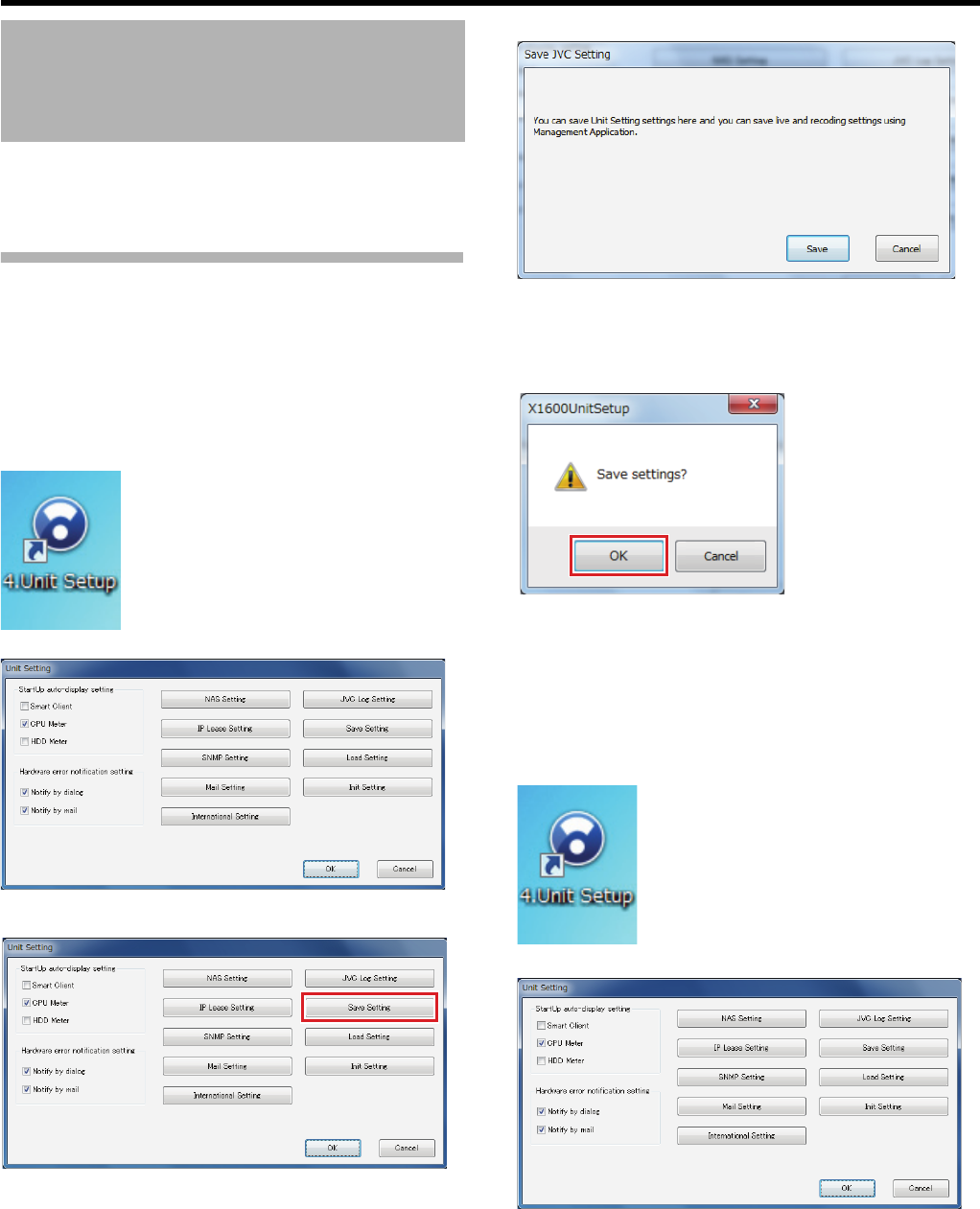
78
<Recorder Part> Applications
You can save the settings for Unit Setting and for
Management Application on a USB flash memory and
restore the previously saved settings.
Saving/Restoring the Settings of
Unit Setting
Settings will be saved on a USB flash memory.
䡵Saving
1 Connect a USB flash memory
2 Double-click [4. Unit Setup] on the desktop
The [Unit Setting] window appears.
3 Click [Save Setting]
A confirmation screen appears.
4 Click [Save]
A confirmation message appears.
5 Click [OK]
The settings are saved.
●When the saving operation is complete, [Saving
succeeded] appears. Click [OK] to close the window.
䡵Restoring
1 Connect a USB flash memory
2 Double-click [4. Unit Setup] on the desktop
The [Unit Setting] window appears.
Saving/Restoring Settings
79
3 Click [Load Setting]
Settings stored on the USB flash memory are displayed.
4 Select a file to load and click [Load]
A confirmation message appears.
5 Click [OK]
The setting is loaded from the USB flash memory.
Saving/Reading the Settings of
Management Application
To save or read the Management Application settings, open
the [File] menu of Management Application. You can save
the settings in xml format anywhere on this unit.
䡵Saving
1 Open the [File] menu and click [Export
Configuration - Backup...]
The saving window appears.
2 Select a storage location and enter the file name
3 Click [Save]
The settings are saved.
Caution:
●Viewer information set on the viewer will not be saved.
䡵Reading Settings
Reading the saved settings and making adjustments.
1 Open the [File] menu and click [Import
Configuration...]
2 Select the file to read and click [Open]
Reading starts.
3 Restart the recording server
The read settings are implemented.
●To restart the recording server, see AWhen you change
settings of Management ApplicationB (A Page 19).

Recorder Part
Reference
This chapter provides lists of setting items of this unit. Also read this chapter when any changes
of system configuration such as camera additions and maintenance are required.
Caution:
●Never turn off the power while saving settings of Management Application.
●When you change settings of Management Application, restart the service; otherwise, the new settings are not applied.
(APage 19 "When you change settings of Management Application") In addition, if you change settings of Management
Application while Smart Client is on, close Smart Client and restart the service.
81
<Recorder Part> Reference
Unit Setup
䢇: Initial value
Setup (This Unit)
Item Preset Values Description
StartUp auto-display setting For selecting the items to be displayed automatically when this unit is
started.
Smart Client Select check box
䢇Do not select
check box
Select this check box to launch the Smart Client at system startup.
CPU Meter
(APage 130)
䢇Select check box
Do not select check
box
Select this check box to launch the CPU meter at system startup.
HDD Meter
(APage 130)
Select check box
䢇Do not select
check box
Select this check box to launch the HDD meter at system startup.
Hardware error notification setting For specifying the error notification method used in the event of any
abnormality of this unit.
Notify by dialog 䢇Select check box
Do not select check
box
Select this check box to display a warning dialog on the screen.
Notify by mail 䢇Select check box
Do not select check
box
Select this check box to notify the registered recipient(s) of any abnormality.

82
<Recorder Part> Reference
NAS Setting (APage 75) For configuring settings for NAS connection.
User name ^For specifying the user name for NAS connection.
Password ^For specifying password for NAS connection.
IP Lease Setting For configuring settings to assign IP addresses to each network camera from
this unit.
Note:
●In order to assign the IP address of the network camera using the IP
Lease feature, you need to enable the DHCP of the network camera. For
procedures to enable the DHCP of the network camera, refer to the
instructions of the network camera.
●
If the network uses more than one of this unit, enable the IP lease function
only for one unit. Also, do not enable the IP lease function when any DHCP
server is running on the same network. Enabling the IP lease function for
more than one unit may cause IPs to be fixed, leading to malfunction of
cameras.
IP Lease feature
Enable IP Lease 䢇Select check box
Do not select check
box
Set whether to assign IP addresses to each network camera from this unit.
Delete past IP
information
Select check box
䢇Do not select
check box
Select this check box to delete past IP information of each network camera
and to assign the new IP address.
Lease period 䢇Unlimited
Limited (24H)
For specifying the valid period of the IP address assigned to the cameras.
Parameters
Head IP address 䢇192.168.0.100 For specifying the first IP address to be assigned to the network cameras.
Number 1 to 99 units
䢇20Units
For selecting the number of IP addresses to be assigned to the cameras.
The selected number of IP addresses will be assigned starting from the first
IP address.
Subnet mask 䢇255.255.255.0 For specifying the subnet mask for the cameras.
Gateway 䢇192.168.0.254 For specifying the gateway for the cameras.
Primary DNS 䢇192.168.0.253 For specifying the primary DNS for the cameras.
Secondary DNS 䢇192.168.0.252 For specifying the secondary DNS for the cameras.
Domain name ^For specifying the domain name for the cameras.
SNMP Setting (APage 126) You can monitor the status of this unit from the SNMP manager on the
surveillance computer.
Enable SNMP Select check box
䢇Do not select
check box
Select this check box to enable the SNMP function.
Enable TRAP Select check box
䢇 Do not select
check box
Select this check box to enable the TRAP function.
SNMP Manager IP
address
^Specify the IP address of the SNMP manager.
Community name ^Specify the SNMP community name.
(1 to 32 characters. Alphanumeric characters only.)
Monitoring interval
CPU Load 10 to 9999 seconds
䢇10 sec
Specify the interval to monitor CPU usage.
D drive writing
rate
30 to 9999 seconds
䢇60 sec
Specify the interval to monitor the writing rate to the D drive.
Smart Client 10 to 9999 seconds
䢇10 sec
Specify the interval to monitor the startup status of the Smart Client.
Camera status 60 to 9999 seconds
䢇60 sec
Specify the interval to monitor the connection status of the camera.
Copy extended MIB file to flash memory Copy the MIB extension information into a USB flash memory.
●For details on SNMP settings, refer to "Setting SNMP" (APage 126).
Item Preset Values Description

83
Mail Setting (APage 59) For configuring mail settings for error notification by mail in the event of any
abnormality of this unit.
Mail to For specifying e-mail address to receive error notification in the event of any
abnormality of this unit.
Add For adding e-mail address(es).
Edit For editing an e-mail address selected in the list.
Delete For deleting an e-mail address selected in the list.
Account setting
SMTP Settings for the outgoing mail server.
Server name ^
Port 䢇25
User ID ^
Password ^
POP Settings for the incoming mail server.
Server name ^
Port 䢇110
User ID ^
Password ^
Mail
Authentication
䢇none
SMTP Authentication
POP before SMTP
Enables you to set the method of user authentication when sending out a
mail. For queries on the settings, consult your system administrator.
Mail from ^For specifying the sender’s e-mail address to send error notification.
Send test mail ^For sending a test mail.
International Setting
Select language 䢇English For selecting the display language used for the [Unit Setting] screen.
JVC Log Setting (APage 128) For specifying the method to save logs.
●Log information may be required for diagnosing problems.
LOG storage
period [Days]
䢇10 For specifying the period for retention of the logs.
Automatically
delete old log file in
case of storage
space shortage.
䢇Select check box
Do not select check
box
Select this check box to delete older logs automatically when the free space
of the destination HDD decreases below 50MB.
Save Setting (APage 78) For saving the contents of the unit settings to a USB flash memory.
Load Setting (APage 78) For displaying the settings stored on the USB flash memory. Select setting(s)
to copy and click [Load].
Init Setting (APage 131) Initialize all UNIT settings. Viewing and recording settings are not initialized.
Item Preset Values Description
84
<Recorder Part> Reference
Network Settings
䡵IP address setting
The settings may be configured in [Network and Internet] in [Control Panel]. Please refer to "Connect This Unit to a Network"
(APage 31).
䢇: Initial value
䡵Host name setting
Make the settings from [Control Panel] B [System and Security] B [System] B [System Details] B [Computer Name] tab B
[Network ID].
Item Preset Values Description
Network adapter interface name For selecting a network you want to configure.
LAN1 Intel(R) 82578DM
Gigabit Network
Connection
Settings when you are using a network with cameras (LAN1).
LAN2 Realtek RTL8168D/
8111D Family PCI-E
Gigabit Ethernet NIC
(NDIS 6.20)
Settings when you are using surveillance computers (LAN2).
Obtain an IP
address
automatically
䢇Select check box
Do not select check
box
Select this check box to obtain an IP address automatically.
IP address 䢇192.168.0.253
Note:
●To specify an IP address other than the default value, consult your system
administrator.
●There is a common host name for LAN1 and LAN2. If the host name is
changed, you need to add a new Windows user. (A Page 66)
Caution:
●Make sure to use LAN1 and LAN2 for different segments*.
Example:
LAN1: 192.168.0.253
LAN2: 192.168.1.253
* Segment: Underlined sections
䢇192.168.1.253
Subnet mask 䢇255.255.255.0
Default gateway
LAN1 ^
LAN2 䢇192.168.1.254
Obtain DNS
server address
automatically
Select check box
䢇Do not select
check box
Preferred DNS
server
^
Alternate DNS
server
^
Item Preset Values
Host Name JVCNVR
DNS Domain
Name
^
85
This section describes procedures to set the date and time of
this unit.
Caution:
●There may be a daily error of 10 to 20 seconds depending
on the operating environment.
●The clock time may vary significantly when the lithium
battery level used for backup in this unit is running low. In
such a case, consult your nearest JVC KENWOOD
dealer.
䡵Using the time server
Use of a time server (NTP server) is recommended to ensure
recording at an accurate time.
Caution:
●Connect the time server to the LAN2 network.
1 Click the [Start] button on the desktop, followed
by clicking [Control Panel]
The control panel opens up.
2 Click [Clock, Language, and Region]
The [Clock, Language, and Region] screen appears.
3 Click [Date and Time] and select [Internet Time]
4 Select [Change settings…]
The [Internet Time Settings] window opens up.
5 Select the [Synchronize with an Internet time
server] check box and select a server
6 Click [OK]
䡵Setting the time manually
If you do not use a time server (NTP server), click [Change
date and time] in [Date and Time] screen in Step 3 in “Using
the time server”.
Setting the Date and Time
of This Unit
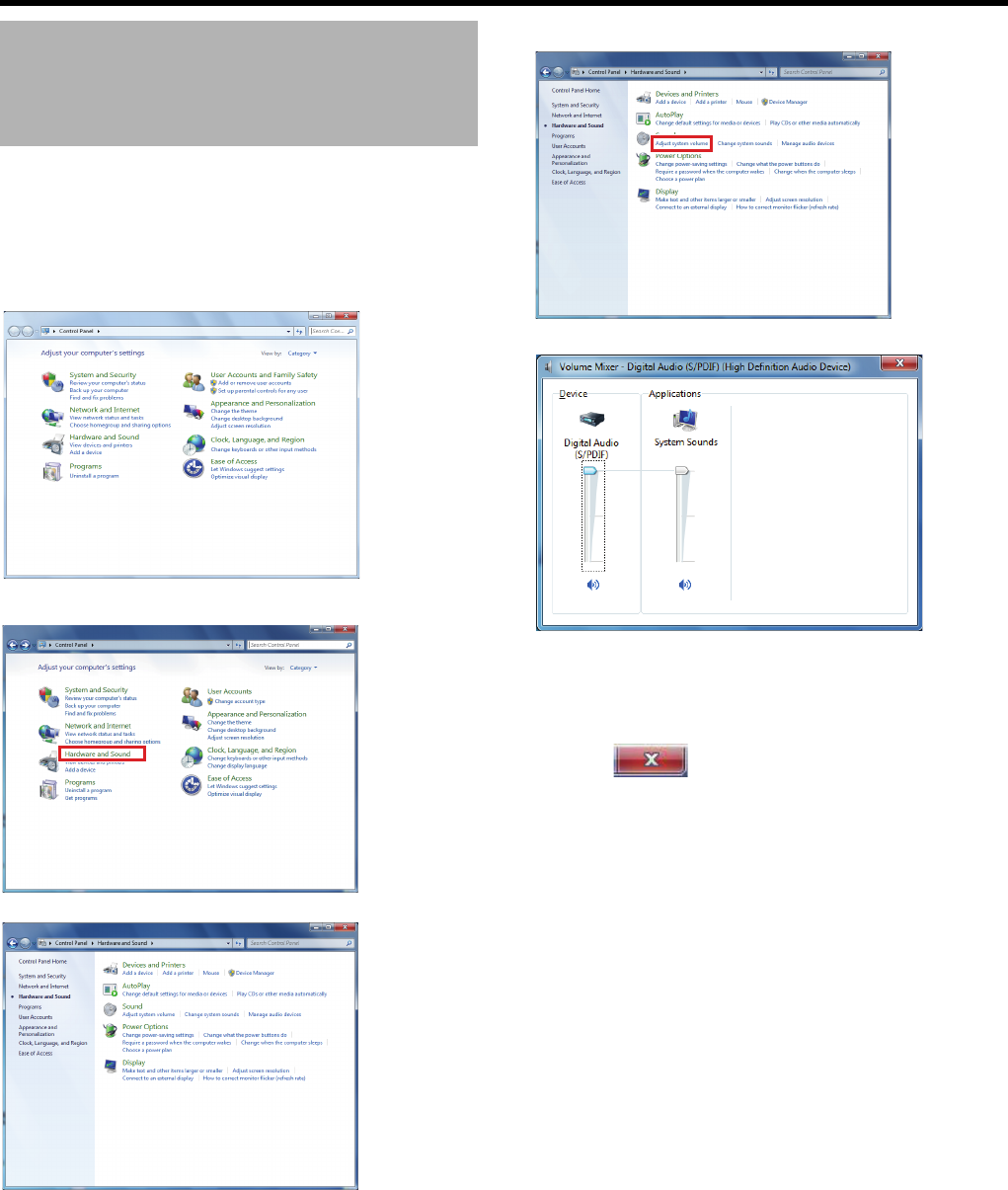
86
<Recorder Part> Reference
This setting is applicable when a speaker is connected with
this unit.
1 Click the [Start] button on the desktop, followed
by clicking [Control Panel]
The control panel opens up.
2 Click [Hardware and Sound]
The [Hardware and Sound] window appears.
3 Click [Adjust system volume]
The [Volume Mixer] window appears.
4 Adjust the volume by dragging the volume slider
in [Device]
●Adjust the volume while listening sound from the
speaker.
5 Click [ (Close)]
Setting the Volume
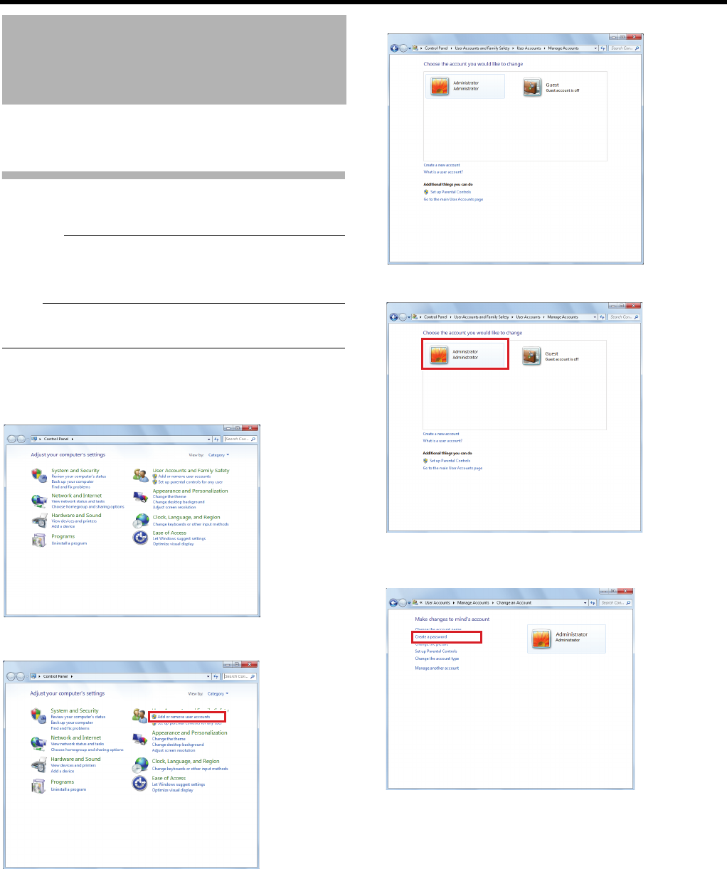
87
This section describes procedures to set a password used to
start this unit.
Setting the Password
Set the password to log in to this unit.
Caution:
●The warning message (APage 195) will not be displayed
unless you login after startup of this unit. In this case, the
[WARNING] indicator lights up.
Note:
●Password is not set by default. If you do not want to use a
password for login, this setting is not necessary.
1 Click the [Start] button on the desktop, followed
by clicking [Control Panel]
The control panel opens up.
2 Click [Add or remove a User Account]
The account selection screen appears.
3 Click [Administrator]
The account modification screen appears.
4 Click [Create a password]
Setting the Password to
Login to This Unit
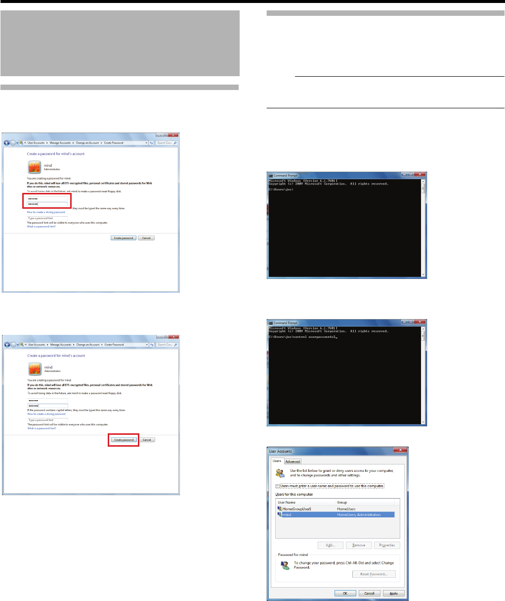
88
<Recorder Part> Reference
Setting the Password (continued)
5 Enter the password
●Enter the password twice for confirmation.
6 Click [Create password]
The password is created.
To validate the created password, see "Validating the
Password" (APage 88).
Validating the Password
Once the password has been set, validate it from the
command prompt and set the password to be entered when
logging in.
Note:
●If the password is not validated, an error will appear when
attempting to log in.
1 Click the [Start] button on the desktop, [All
Programs], [Accessories], then click [Command
Prompt]
The command prompt starts up.
2 Enter [control userpasswords2], then press the
enter key on the keyboard
The [User Accounts] window appears.
Setting the Password to
Login to This Unit
(continued)
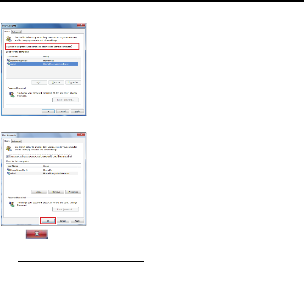
89
3 Select [Users must enter a user name and
password to use this computer]
4 Click [OK]
5 Click [ (Close)] to close the command
prompt
Note:
●To log in automatically, deselect [Users must enter a user
name and password to use this computer] in step 3.
●To display the screen keyboard on the Windows login
screen (after the password is valid), click the [Ease of
access] button, then activate [Type without the keyboard
(On-Screen Keyboard)].
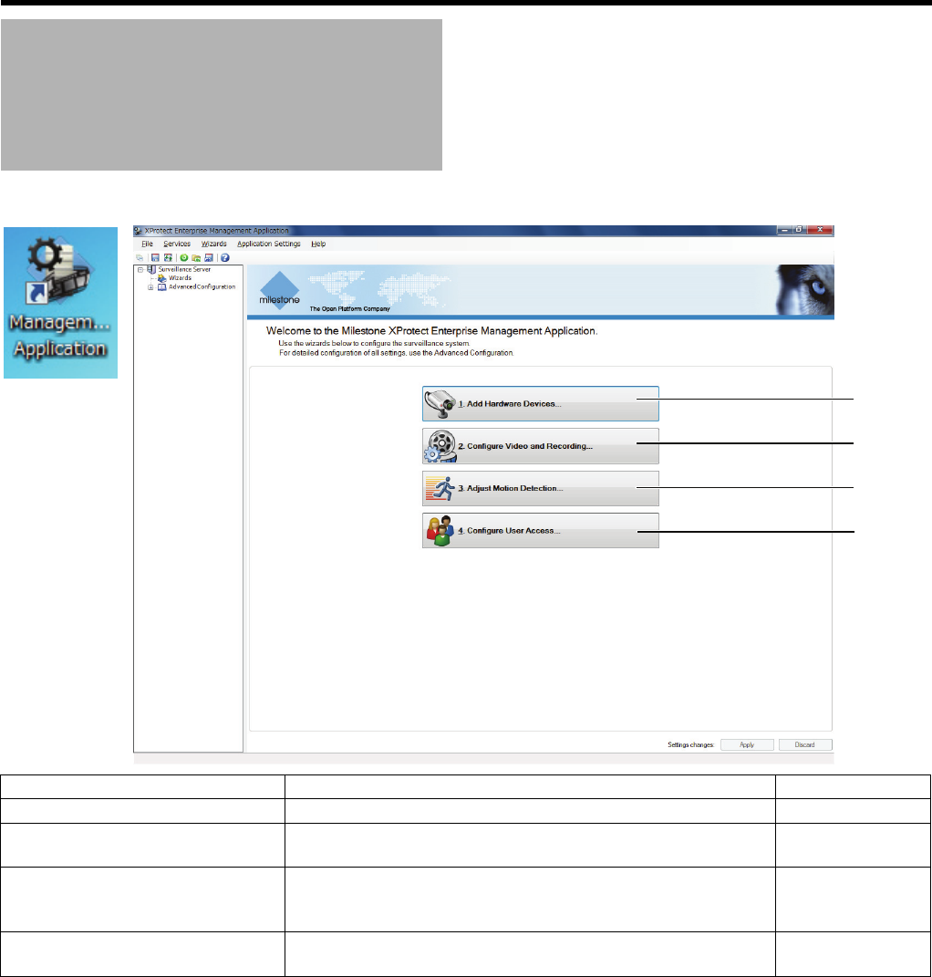
90
<Recorder Part> Reference
The wizard setup of Management Application allows you to configure basic setting items in order.
Management Application
(Wizards)
1
2
3
4
Item Description Reference
AAdd Hardware Devices... For registering network cameras. A Page 33
BConfigure Video and
Recording...
For configuring settings related to camera images and recording. A Page 34
CAdjust Motion Detection... For configuring settings related to motion detection. This setting is
not necessary if the recording condition is not set to [Motion
detection] in [Configure Video and Recording...].
A Page 44
DConfigure User Access... This section describes procedures to register user(s) of Smart
Client and configure the rights of each user.
A Page 66
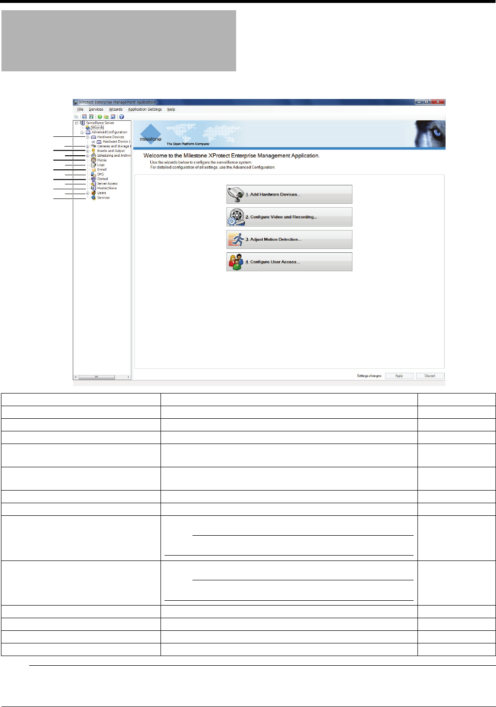
91
Note:
●When an item is clicked, a summary of the settings appears.
●When there are items below, click [+] to display them.
●When you double-click an item, the properties window appears and detailed settings can be made.
Management Application
(Advanced Configuration)
2
4
6
8
0
1
3
5
7
9
-
~=
Item Description Reference
AHardware Devices
For displaying properties and settings of devices connected to the system.
A Page 92
B
Cameras and Storage Information
For specifying the frame rate and storage location of camera images.
A Page 100
CEvents and Output For configuring various event settings. A Page 105
DScheduling and Archiving For specifying various schedules for recording, archiving,
notification, and PTZ patrolling, etc.
A Page 107
EMatrix For configuring settings of Matrix function to distribute images
upon the occurrence of any event.
A Page 109
FLogs For configuring settings for logging. A Page 109
GE-mail For configuring e-mail notification settings. A Page 110
HSMS For configuring SMS notification settings.
Note:
●This unit does not support notifications by SMS.
^
ICentral Settings for using Milestone's Milestone XProtect Central.
Note:
●This unit does not support Central functions.
^
JServer Access For configuring settings related to servers. A Page 111
KMaster/Slave
For configuring master/slave settings in case more than one NVR is used.
A Page 112
LUsers For adding/changing users and/or user rights. A Page 112
MServices
For starting/stopping various services of Management Application.
A Page 113

92
<Recorder Part> Reference
Hardware Devices
䢇: Initial value
Item Preset Values Description
Hardware Devices (Hardware Properties)
Name and
Video
Channels
Hardware
name and
video
channels
Hardware name ^Name used to identify the device. You cannot assign the
same name to multiple devices.
●The following characters cannot be used.< > & ' " \ / :
* ? | [ ]
Enable Select check box
Do not select check
box
Select this check box to use this device.
●Default value varies depending on devices.
Network,
Device
Type and
License
Network Address ^IP address or DNS host name of the device.
HTTP port 䢇80 If [Use default HTTP port] is selected, HTTP
communication to the unit will be performed through the
default port number 80. To use another port, deselect
the check box and specify the port number in the field to
the left of the check box. Default value for [Use default
HTTP port] varies depending on the device.
FTP port 䢇21 If [Use default FTP port] is selected, FTP
communication to the unit will be performed through the
default port number 21. To use another port, deselect
the check box and specify the port number in the field to
the left of the check box. Default value for [Use default
FTP port] varies depending on the device.
User Name ^Enter the password for logging into the device using the
root account (also known as Admin or Administrator
account).
Password ^
Device type Hardware type For selecting the type of device from the list.
Serial number (MAC address) Serial number of the device. The 12-character MAC
address of the device is normally used.
Device license key (DLK) Not used.
Replace Hardware Device Replace the device in use with a new one (APage 118
"Replacing a Hardware Device").

93
Hardware Devices (Hardware Properties) (continued)
PTZ Device PTZ
settings
Connected
cameras have
Pan/Tilt/Zoom
capabilities
Select check box
䢇Do not select
check box
Select this check box when a PTZ camera is included in
the cameras connected to the unit. If this check box is
not selected, the PTZ function is not available.
PTZ type on
COM1
䢇None
JCBP-S
Pelco-P
Pelco-D
Select a control method suitable for PTZ camera(s) if
the camera is controlled through the COM1/COM2 port
of the network encoder (IP video server). Select [None]
when no PTZ cameras are controlled through the
COM1/COM2 port.
PTZ type on
COM2
Camera The camera name is displayed.
Ty p e 䢇Fixed
Moveable
Select whether the camera is [Fixed] or [Moveable].
[Fixed]: Fixed camera
[Moveable]: PTZ camera
Port COM1
COM2
Available when [Moveable] is selected for [Type].
Select the control port of the network encoder (IP video
server) to control the PTZ function.
Port Address 䢇0Available when [Moveable] is selected for [Type].
Specify the camera’s port address. Normally, specify
the address as “0” or “1”.
When series connection is applied for PTZ cameras,
the unit identifies the cameras by the port address.
Confirm the recommended setting for each camera
referring to the camera’s instruction.
Fisheye Fisheye Enable fisheye Select check box
䢇Do not select
check box
Select this check box to use the fisheye lens function.
Fisheye license key For specifying the license key to use the fisheye lens
function.
●For details on purchasing a license key, consult our
authorized dealers or JVC KENWOOD service
center.
Item Preset Values Description

94
<Recorder Part> Reference
Camera (Camera Properties)
Camera
Properties
General
camera
settings
Enabled Select check box
Do not select check
box
Select this check box to use this camera. Default value
varies depending on the camera.
Camera name ^The name is used to identify the selected camera. Do
not assign the camera name already used for other
devices.
●The “Camera name” is not the name specified for the
camera unit, but for identifying the camera on this
unit.
●The following characters cannot be used.< > & ' " \ /
: * ? | [ ]
Camera
shortcut number
^For specifying the camera number.
●Do not assign a camera number that is used by other
cameras.
Frame rate Frame rate
selection
(MJPEG)
Regular frame
rate:
Live frame rate
1 to 10, 15, 20, 25,
30,
Second, Minute, Hour
䢇20 Second
For specifying the frame rate for live display.
Regular frame
rate:
Recording frame
rate
䢇10.00 Second For specifying the frame rate for recording.
● The values that can be specified differ depending on
the settings for [Regular frame rate: Live frame rate].
●You cannot specify values larger than [Regular frame
rate: Live frame rate].
Enable speedup Select check box
䢇Do not select
check box
Select this check box to use the speedup function.
●The speedup function is enabled by [Motion
detection] or [Event].
Speedup frame
rate:
Live frame rate
䢇20 Second For specifying the frame rate for live display when the
speedup function is enabled.
●The values that can be specified differ depending on
the settings for [Regular frame rate: Live frame rate].
●You cannot specify values smaller than [Regular
frame rate: Live frame rate].
Speedup frame
rate:
Recording frame
rate
䢇10.00 Second For specifying the frame rate for recording when the
speedup function is enabled.
●
The values that can be specified differ depending on
the settings for [Speedup frame rate: Live frame rate].
●You cannot specify values larger than [Speedup
frame rate: Recording frame rate].
On motion Select check box
䢇Do not select
check box
For specifying whether or not the speedup setting is
enabled to increase the frame rate for recording when
any motion detection or event occurs. Select this check
box to enable it.
●If the [Event] check box is selected, set the start
event and stop event.
On Event Select check box
䢇Do not select
check box
Start event 䢇^
Stop event
Configure
events
Hardware input
events
Manual events
Generic events
䢇^
Select an event and click [Open] to display the settings
screen for the selected event.
Caution:
●Be sure to set the frame rate so that the total frame rate does not exceed the performance capacity of this unit. For the
performance of this unit, see ARecording/Displaying live images/Distribution performanceB (APage 196).
Item Preset Values Description

95
Camera (Camera Properties) (continued)
Video Video Properties
Configure Video
Properties
^Click to display the [Video Properties] screen.
Make detailed display settings for the selected camera.
Note:
●The displayed items and initial settings differ
depending on the camera. For details, see the
instruction manual of the camera.
Preview ^For displaying the preview.
Audio Audio
selection
Default
microphone
^This setting is applicable when microphones and/or a
speaker are used. Available microphones/speakers
vary depending on the camera.
Default speaker ^
Recording
Properties
Recording Recording
settings
Always
Never
Conditionally
Always: Select this check box to always record images.
Never: For recording images manually without
recording settings.
Conditionally: For setting the conditions to record
images.
●Default value varies depending on the camera.
●Configure settings below when you select
[Conditionally].
Built-in motion
detection
Select check box
䢇Do not select
check box
Select this check box to record all images where any
motion is detected.
Event Select check box
䢇Do not select
check box
Select this check box to start recording at the
occurrence of an event.
●If the [Event] check box is selected, set the start
event and stop event.
Start event ^
Stop event
Configure
Events
Hardware input
events
Manual events
Generic events
䢇^
Select an event and click [Open] to display the settings
screen for the selected event.
Enable pre-
recording
Select check box
䢇Do not select
check box
Images before/after the occurrence of motion or an
event can be recorded. You can specify units of
seconds to record before/after the occurrence.
●Default value varies depending on the camera.
second(s) ^
Enable post-
recording
Select check box
䢇Do not select
check box
second(s) ^
Item Preset Values Description

96
<Recorder Part> Reference
Camera (Camera Properties) (continued)
Recording
and
Archiving
Paths
Recording
settings
Recording path D:\MediaDatabase Do not change this setting.
Archiving path 䢇Using dynamic
path
For specifying the archiving destination of the database.
●You can not specify the destination when a dynamic
path is used.
Retention Time Day(s), Hour(s),
Minute(s)
䢇7 Day(s)
For saving records to the database until the record
reaches the predefined recording time. Specify the
recording time in the next field and select the unit of
time (Minute(s), Hour(s), or Day(s)) from the list.
Database repair
action
䢇Repair, scan,
delete if fails
Repair, delete if fails
Repair, archive if fails
Delete (no repair)
Archive (no repair)
For selecting the action to take when problems are
found in the database. The number of options available
varies depending on whether archiving is enabled.
Caution:
●Select [Archive (no repair)] in normal circumstances.
If you have selected another option, the data may be
lost if problems occur in the database.
Repair, scan, delete if fails:
Two different repair methods, quick repair (recovery)
and complete repair (scan), are used. Content of the
database will be deleted if both repair methods fail.
Repair, delete if fails:
The fast repair method is used. Content of the database
will be deleted if fast repair fails.
Repair, archive if fails:
This option is available only if archiving is enabled for
the camera. The fast repair method is used. Content of
the database will be archived if fast repair fails.
Delete (no repair):
Do not select this item.
Archive (no repair):
This option is available only if archiving is enabled for
the camera. Content of the database is archived. Select
this option.
Item Preset Values Description

97
Camera (Camera Properties) (continued)
General archiving settings for all cameras For configuring common archiving settings for all
cameras.
Configure
Dynamic
Paths...
Enable dynamic
path selection
for archives
䢇Select check box
Do not select check
box
Select this check box to automatically select an
archiving destination drive from the registered list.
The registered archiving destination will be listed along
with the drive, path, capacity and free space.
Deselecting the [Use] check box will disable the
selection.
Use 䢇Select check box
Do not select check
box
Drive ^
Path ^
Drive Size ^
Free Space ^
New UNC path ^For specifying a drive path you want to register for
automatic selection by dynamic path.
Event
Notification
Event
notification
Available events Hardware
Manual
Generic
You can view the yellow display in the title bar area on
the upper part of the live image display screen in case a
specific event occurs.
●Select an event from the [Available events] list and
move it to the [Selected events] list.
Selected events 䢇None
Configure
events
Hardware input
events
Manual events
Generic events
䢇^
Select an event and click [Open] to display the settings
screen for the selected event.
Output Output
activation
Available output 䢇None For displaying the available output ports.
On manual
activation
䢇None For specifying an output port to output when a specific
event or manual event occurs.
On motion
detected
䢇None For specifying an output port to output when motion is
detected.
Configure
events
Hardware input
events
Manual events
Generic events
䢇^
Select an event and click [Open] to display the settings
screen for the selected event.
Motion
Detection
and Exclude
Regions
(
A
Page 44)
Motion
detection
Sensitivity 0 to 256
䢇40
For determining the level of change in the image pixel
that is to be recognized as motion. As the value is
decreased, the sensitivity is increased, and minor
changes in the pixels are recognized as motion.
Motion 0 to10000
䢇640
For determining the number of pixels for which a
change is to be recognized as motion. When the slider
is moved from side to side, the black vertical line at the
bottom of the screen moves together, and the boundary
(Motion Sensitivity) is adjusted. When detected motion
exceeds the selected sensitivity level, the bar changes
from green to red, indicating a positive detection.
Motion detection
interval
䢇240 milliseconds For specifying the motion detection interval.
Exclude
regions
Enable Select check box
䢇Do not select
check box
Select this check box to specify region(s) where the
motion detection is disabled.
Show Grid Select check box
䢇Do not select
check box
Select this check box to show the grid on the preview
screen.
Item Preset Values Description

98
<Recorder Part> Reference
Camera (Camera Properties) (continued)
PTZ Preset
Positions
(
A
Page 39)
PTZ preview ^For directing the PTZ camera to any position.
Audio
selection
Default
microphone
^This setting is applicable when microphones and/or a
speaker are used. Available microphones/speakers
vary depending on the camera.
Default speaker ^
PTZ preset
positions
PTZ Type Type 1 (stored on
server)
Type 2 (stored on
server)
Type 3 (stored on
camera)
Type 1 (stored on server): For setting and saving a
preset position on the server.
Type 2 (stored on camera): Click [Import/Refresh], then
read the preset position from the camera. The preset
position is saved on this unit.
Type 3 (stored on camera): Click [Import/Refresh]. The
preset position is imported from the camera and stored
on the camera.
Note:
●When using a JVC camera, it is recommended to
select the more positionally accurate [Type 3]. (Not
selectable depending on the camera.)
Add New ^For adding a preset position you just set to the list.
Set New
Position
^For modifying a preset position selected in the list. Use
the PTZ preview screen to modify the position.
Delete ^For deleting a preset position selected in the list.
Test ^For testing a preset position.
PTZ
Patrolling
Patrolling profiles ^For displaying a defined patrol and creating a new
patrolling profile.
(
A
Page 41)
Patrolling
Profiles
^For displaying a defined patrolling profile.
Add New ^For creating a new patrolling profile.
Delete ^For deleting a patrolling profile selected in the list.
Patrolling list ^For editing the patrolling details.
Preset Positions ^For displaying a defined preset position on the selected
camera. Select a preset position you want to add to the
patrolling profile and click [ ] and then it is added to
the profile.
Patrolling List ^For displaying a preset position registered with the
patrolling profile. To delete it from the patrolling profile,
select a preset position you want to delete and click
[].
Wait time (sec.) 䢇10 For specifying the period for which the camera stops in
each preset position.
Transition time
(sec.)
䢇5For specifying the period for which the camera moves
between preset positions. During the period, motion
detection is disabled.
Item Preset Values Description

99
Camera (Camera Properties) (continued)
PTZ
Patrolling
(continued)
PTZ scanning Select check box
䢇Do not select
check box
For confirming and specifying the scanning speed in
case of a camera with the PTZ scanning function.
(Speed) High
䢇Medium
Low
Pause
patrolling
Pause patrolling
if motion is
detected
Select check box
䢇Do not select
check box
Select this check box to pause patrolling when any
motion is detected.
Resume
patrolling
seconds after first
motion detection
For specifying timing to resume the patrolling paused
due to motion detection.
seconds after last
motion is detected
Resume PTZ
patrolling after
䢇30 seconds For specifying timing to resume manual PTZ operation
or to resume patrolling interrupted due to an event.
PTZ on event
(APage 52)
Event 䢇None For specifying a combination of an event and a preset
position in case the PTZ camera is configured to be
moved by an event.
PTZ Preset
Position
䢇None
Item Preset Values Description

100
<Recorder Part> Reference
Cameras and Storage Information
䢇: Initial value
Item Preset Values Description
Recording and Archiving Paths
Template For displaying template settings.
Recording Path D:\MediaDatabase Do not change this setting.
Archiving Path 䢇Using dynamic
path
For specifying the archiving destination of the
database.
●You can not specify the destination when a dynamic
path is used.
Retention Time Day(s), Hour(s),
Minute(s)
䢇7 Day(s)
For saving records to the database until the record
reaches the predefined recording time. Enter the
recording time, then select a unit from the list.
(For each camera) For configuring settings for each camera.
Apply Template Select check box
䢇Do not select
check box
Select this check box to apply the template setting.
Note:
●Click [Select All] to select check boxes of all
cameras.
●Click [Clear All] to deselect check boxes of all
cameras.
Camera Name ^For displaying the camera name.
Shortcut ^For specifying the camera number.
●Do not assign a camera number that is used by
other cameras.
Recording Path D:\MediaDatabase Do not change this setting.
Archiving Path 䢇Using dynamic
path
For specifying the archiving destination of the
database.
●You can not specify the destination when a dynamic
path is used.
Retention Time Day(s), Hour(s),
Minute(s)
䢇7 Day(s)
For saving records to the database until the record
reaches the predefined recording time. Specify the
recording time in the next field and select the unit of
time (Day(s), Hour(s), Minute(s)) from the list.
Cameras Open For displaying the [Camera Properties] window.
Dynamic Path Selection – Archives
Dynamic path
selection - All
cameras
Enable dynamic path
selection for archives
Select check box
Do not select check
box
Select this check box to automatically select an
archiving destination drive from the registered list.
●Default value varies depending on the camera.
Use ^The registered archiving destination will be listed along
with the drive, path, capacity and free space.
Deselecting the [Use] check box will disable the
selection.
Drive ^
Path ^
Drive Size ^
Free Space ^
New UNC path ^For specifying a drive path you want to register for
automatic selection by dynamic path.

101
Video Recording
Template For displaying template settings.
Record on Always
Never
䢇Motion
detection
Event
Event and motion
detection
For selecting a recording method.
Start Event 䢇None For specifying an event to start recording and an event
to stop recording.
Stop Event
Pre-recording Select check box
䢇Do not select
check box
Images before/after the occurrence of motion or an
event can be recorded. You can specify units of
seconds to record before/after the occurrence.
Second(s) 䢇3
Post-recording 䢇Select check
box
Do not select check
box
Second(s) 䢇3
(For each camera) For configuring settings for each camera.
Apply Template Select check box
䢇Do not select
check box
Select this check box to apply the template setting.
Note:
●Click [Select All] to select check boxes of all
cameras.
●Click [Clear All] to deselect check boxes of all
cameras.
Record on Always
Never
䢇Motion
detection
Event
Event and motion
detection
For selecting a recording method.
Start Event 䢇None For specifying an event to start recording and an event
to stop recording.
Stop Event
Pre-recording Select check box
䢇Do not select
check box
Images before/after the occurrence of motion or an
event can be recorded. You can specify units of
seconds to record before/after the occurrence.
●Default value varies depending on the camera.
Second(s) ^
Post-recording 䢇Select check
box
Do not select check
box
Second(s) ^
Manual Recording
Manual Recording Enable manual
recording
Select check box
Do not select check
box
Select this check box to use the manual recording
function.
●Default value varies depending on the camera.
Default duration of
manual recording
䢇300 sec For specifying the recording time for manual recording.
Recording will end automatically after the defined time.
Maximum duration of
manual recording
䢇1800 sec For specifying the maximum duration of manual
recording.
Item Preset Values Description

102
<Recorder Part> Reference
Frame Rate - MJPEG
Frame rate (MJPEG)
Regular Frame Rate
Live Frame Rate 1 to 10, 15,
䢇20, 25, 30
For specifying the frame rate for normal live display.
Note:
●
The validated setting value differs depending on the
camera. Refer to the instruction manual of the camera
and confirm the validated setting value before setting.
Recording Frame
Rate
䢇10.00 For specifying the frame rate for normal recording.
●
The values that can be specified differ depending on
the settings for [Regular frame rate: Live frame rate].
●You cannot specify values larger than [Regular
frame rate: Live frame rate].
Note:
●
The validated setting value differs depending on the
camera. Refer to the instruction manual of the camera
and confirm the validated setting value before setting.
Time Unit 䢇Second
Minute
Hour
For specifying the time unit.
Apply Template Select check box
䢇Do not select
check box
Select this check box to use a template when you
configure settings for each camera.
Note:
●
Click [Select All] to select check boxes of all cameras.
●
Click [Clear All] to deselect check boxes of all cameras.
Camera Open For displaying the [Camera Properties] window.
Speedup Frame Rate
Enable Speedup Select check box
䢇Do not select
check box
Validates speedup.
Live Frame Rate 䢇20 For specifying the frame rate for speedup live display.
●
The values that can be specified differ depending on
the settings for [Regular frame rate: Live frame rate].
● You cannot specify values larger than [Regular
frame rate: Live frame rate].
Caution:
●Be sure to set the frame rate so that the total frame
rate does not exceed the performance capacity of
this unit. For the performance of this unit, see
ARecording/Displaying live images/Distribution
performanceB (APage 196).
Recording Frame
Rate
䢇10.00 For specifying the frame rate for speedup recording.
●
The values that can be specified differ depending on the
settings for [Speedup frame rate: Live frame rate].
●You cannot specify values larger than [Speedup
frame rate: Live frame rate].
Caution:
●Be sure to set the frame rate so that the total frame
rate does not exceed the performance capacity of
this unit. For the performance of this unit, see
ARecording/Displaying live images/Distribution
performanceB (APage 196).
Time Unit 䢇Second
Minute
Hour
For specifying the time unit.
Item Preset Values Description

103
Frame Rate - MJPEG (continued)
Frame rate (MJPEG) (continued)
Speedup Frame Rate (continued)
Speedup on Motion Detection
䢇Event
Event and motion
detection
Schedule only
Set when the speed up setting is activated.
Start Event
Stop Event
䢇None When [Speedup on] is set to [Event] or [Event and
motion detection], select the start/stop event.
Apply Template Select check box
䢇Do not select
check box
Select this check box to use a template when you
configure settings for each camera.
Note:
●Click [Select All] to select check boxes of all
cameras.
●Click [Clear All] to deselect check boxes of all
cameras.
Camera Open For displaying the [Camera Properties] window.
Frame Rate - MPEG
Frame rate (MPEG) Live FPS 1 to 10, 15, 20 For specifying the frame rate in live display.
Note:
●The validated setting value differs depending on the
camera. Refer to the instruction manual of the
camera and confirm the validated setting value
before setting.
Record Keyframes
Only
Select check box
䢇Do not select
check box
Select this check box to record keyframes (I Frame)
only.
Record All Frames on Motion detection
Event
Event and motion
detection
䢇Schedule only
For selecting conditions for recording all frames.
Start Event 䢇None For specifying an event to start recording and an event
to stop recording.
Stop Event
Apply Template Select check box
䢇Do not select
check box
Select this check box to use a template when you
configure settings for each camera.
Note:
●Click [Select All] to select check boxes of all
cameras.
●Click [Clear All] to deselect check boxes of all
cameras.
Camera Open For displaying the [Camera Properties] window.
Item Preset Values Description

104
<Recorder Part> Reference
Audio Selection
Audio selection Default Microphone 䢇None This setting is applicable when microphones and/or a
speaker are used.
Default Speaker 䢇None
Apply Template Select check box
䢇Do not select
check box
Select this check box to use a template when you
configure settings for each camera.
Note:
●Click [Select All] to select check boxes of all
cameras.
●Click [Clear All] to deselect check boxes of all
cameras.
Camera Open For displaying the [Camera Properties] window.
Audio Recording
Audio recording Record audio - all
cameras
䢇Always
Never
For selecting whether to record audio sound together
with images.
Storage Information
Storage information Drive Information of the storage currently used is displayed.
Path, capacity, video data amount, other data amount
and free space are displayed for each drive.
Path
Usage
Drive Size
Video Data
Other Data
Free Space
Item Preset Values Description

105
Events and Output
䢇: Initial value
Item Preset Values Description
Ports and Polling
Ports and
polling
Alert and generic event port 1 to 65535
䢇1234
For specifying a port number to handle a warning
triggered by an event, such as a generic event.
SMTP event port 1 to 65535
䢇25
For specifying a port number to send event
information from a device to the monitoring
system via SMTP.
FTP event port 1 to 65535
䢇21
For specifying a port number to send event
information from a device to the monitoring
system via FTP.
Polling interval [1/10] second 䢇10 (1 sec) For some devices, the monitoring system must
check the status of device input port to detect
whether or not the input has been received. Such
regular status check is referred to as “polling.”
●For I/O devices, set the polling interval as
short as possible.
●For devices that require polling, refer to the
relevant instruction manuals for I/O devices.
Hardware Input Events (APage 48)
(Hardware
Device name)
Event
configuration
Enable event 䢇Select check
box
Do not select
check box
Select this check box to use the event function.
Note:
●The following setting items vary depending on
selected events.
Event name For specifying an event name.
●The following characters cannot be used. < > & ' " \ / : * ? | [ ]
Pre/post alarm
images
Images from
camera
^For selecting cameras to acquire images.
Number of pre-
alarm images
䢇3For specifying the number of images to acquire.
Frames per
second
䢇1For specifying the number of image frames.
E-mail
notification
Send e-mail if
this event
occurs
Select check box
䢇Do not select
check box
Select this check box to send an e-mail when an
event occurs.
Attach image
from camera
Select check box
䢇Do not select
check box
Select this check box when you attach an image
to the e-mail, and select an image source by
using the pull-down menu.
SMS notification Send SMS if
this event
occurs
Select check box
䢇Do not select
check box
Note:
●This unit does not support notifications by
SMS.
System motion
detection event
Create a
system motion
detection event
for the camera
Select check box
䢇Do not select
check box
Select this check box when you create an event
to be triggered by motion detection.
Hardware Output (APage 56)
(Hardware
Device name)
Output Settings Output name For specifying a name for the output.
●The following characters cannot be used. < > & ' " \ / : * ? | [ ]
Output
connected to
For selecting which destination to connect the output to.
Keep output for For specifying the output holding time in units of 1/10 seconds or
seconds.
Test Output Click this to perform a test on the output settings.

106
<Recorder Part> Reference
Manual events (APage 50)
Global/(Manual
Event name)
Event
configuration
Event name For specifying an event name.
●The following characters cannot be used. < > & ' " \ / : * ? | [ ]
E-mail
notification
Send e-mail if
this event
occurs
Select check box
䢇Do not select
check box
Select this check box to send an e-mail when an
event occurs.
Attach image
from camera
Select check box
䢇Do not select
check box
Select this check box when you attach an image
to the e-mail, and select an image source by
using the pull-down menu.
SMS notification Send SMS if
this event
occurs
Select check box
䢇Do not select
check box
Note:
●This unit does not support notifications by
SMS.
Generic Events (APage 46)
(Generic event
name)
Event
configuration
Event name ^For specifying an event name.
●The following characters cannot be used. < >
& ' " \ / : * ? | [ ]
Event
substring
^Enter the words to be used as keywords when
analysing the received character string. When
[Add] is clicked for and entered word, it is added
to [Event message expression].
●The following characters cannot be used. < >
& ' " \ / : * ? | [ ]
Event
message
expression
^The added words are displayed. Use the
following buttons to edit the conditions.
●(): Bundle related words.
Words enclosed with () are prioritized over
other words.
●AND: Insert between words which must both
be included.
●OR: Insert between words where either is
required.
●Delete: Delete the word to the left of the
cursor.
Event protocol Any
䢇TCP
UDP
Choose which protocol this unit uses to receive
on the detection of an event.
Event rule type Match
䢇Search
Set the rule for analysing the received data (data
which exactly matches is analysed, or data which
partially matches is analysed).
Event priority 0 to 1000
䢇0
Each event is prioritized to determine which
event will function when the received data
complies with more than on event rule.
E-mail
notification
Send e-mail if
this event
occurs
Select check box
䢇Do not select
check box
Select this check box to send an e-mail when an
event occurs.
Attach image
from camera
Select check box
䢇Do not select
check box
Select this check box when you attach an image
to the e-mail, and select an image source by
using the pull-down menu.
SMS notification Send SMS if
this event
occurs
Select check box
䢇Do not select
check box
Note:
●This unit does not support notifications by
SMS.
Item Preset Values Description

107
Scheduling and Archiving
䢇: Initial value
Output Control on Event
Output on
Event
Activate output
on event
Event ^Set the combination of set events and outputs.
Output ^
Configure events I/O input events
Manual events
Generic events
Select an event and click [Open] to display the
settings screen for the selected event.
Configure Output... ^Display the output settings screen (A Page 105
"Hardware Output").
Item Preset Values Description
Item Preset Values Description
Scheduling All Cameras (APage 121)
Schedule all cameras For specifying options for Online, Speedup, Send e-
mail/SMS, and PTZ patrolling schedule for each
camera.
Note:
●This unit does not support notifications by SMS.
Online 䢇Always off
Always onSpeedup
E-mail
SMS
PTZ Patrolling 䢇None
Apply Template (for each camera) Select check box
䢇
Do not select check box
Select this check box to use a template when you
configure settings for each camera.
Scheduling Options
Scheduling options Start cameras on
client request
Select check box
䢇
Do not select check box
Select this check box to start the camera on request
from the viewer.
Schedule profile
for new cameras
Always off
Always on
For specifying the default schedule value applied to
any new camera added.
●Default value varies depending on the camera.
Hardware device
communication
Maximum delay
between reconnect
attempts
䢇10 For specifying the maximum delay for reconnect.
Restore Default ^Reset the maximum delay time for reconnection.
Archiving
Archiving time 䢇12:00:00 For specifying the archiving time.
Archive failure
notification
Send e-mail on
archive failure
䢇Select check box
Do not select check box
Select this check box to send an e-mail when any
failure occurs during archiving.
Send SMS on
archive failure
䢇Select check box
Do not select check box
Note:
●This unit does not support notifications by SMS.

108
<Recorder Part> Reference
(Camera name)
Online Period (APage 123)
Online schedule Schedule
profiles
䢇Always on
Always off
For selecting a schedule profile.
Set camera to start/stop on time 䢇Select check box
Do not select check box
For activating/deactivating cameras at a specified
time.
Set camera start/stop on event Select check box
䢇
Do not select check box
For activating/deactivating cameras when an event
occurs.
Start event ^For specifying a start event and a stop event.
Stop event ^
Configure Events Hardware Input Events
Manual Events
Generic Events
䢇^
Select an event and click [Open] to display the
settings screen for the selected event.
Start time 0:00 to 23:59 For specifying the start time and stop time.
End time
Day
Monday to Sunday,
Weekdays, Everyday
For specifying the duration.
Speedup (APage 123)
Speedup schedule Schedule
profiles
Always off
Always on
For selecting a schedule profile.
●Default value varies depending on the camera.
Start time 0:00 to 23:59 For specifying the start time and stop time.
End time
Day
Monday to Sunday,
Weekdays, Everyday
For specifying the duration.
E-mail Notification (APage 123)
E-mail schedule Schedule
profiles
Always off
Always on
For selecting a schedule profile.
●Default value varies depending on the camera.
Start time 0:00 to 23:59 For specifying the start time and stop time.
End time
Day Monday to Sunday,
Weekdays, Everyday
For specifying the duration.
SMS Notification
Note:
●This unit does not support notifications by SMS.
SMS schedule Schedule
profiles
Always off
Always on
For selecting a schedule profile.
●Default value varies depending on the camera.
Start time 0:00 to 23:59 For specifying the start time and stop time.
End time
Day Monday to Sunday,
Weekdays, Everyday
For specifying the duration.
PTZ Patrolling (APage 124)
PTZ Patrolling
schedule
Schedule
profiles
䢇None For selecting a schedule profile.
●Default value varies depending on the camera.
Patrolling profile ^For selecting a patrolling profile.
Start time 0:00 to 23:59 For specifying the start time and stop time.
End time
Day Monday to Sunday,
Weekdays, Everyday
For specifying the duration.
Item Preset Values Description

109
Matrix
䢇: Initial value
Logs
䢇: Initial value
Item Preset Values Description
Matrix Recipients (APage 53)
Matrix recipients Enable Matrix Select check box
䢇Do not select
check box
For enabling the Matrix function to distribute images at the
occurrence of an event.
Name ^For specifying the recipient of the images distributed by
the Matrix function.
Address ^
Port ^
Password ^
Matrix recipient is a
Smart Client
䢇Select check
box
Do not select check
box
Matrix Event Control (APage 53)
Matrix event
control
Configure events Hardware Input
Events
Manual Events
Generic Events
Select an event and click [Open] to display the settings
screen for the selected event.
Item Preset Values Description
Logs (APage 128)
Logs Path 䢇L:\Log\MS For specifying the path of the storage location of system
log files.
Days to log 䢇10 For specifying the number of days for storing the system
log files.
Event log Path 䢇L:\Log\MS For specifying the path of the storage location of event log
files.
Caution:
●Do not change this setting.
Days to log 䢇10 For specifying the number of days for storing the event log
files.
Audit log Enable audit
logging
Select check box
䢇Do not select
check box
Enables you to configure log file settings related to client
computer users.
Select this check box to enable logging.
Path 䢇L:\Log\MS\ISAud
itLog
For specifying the path of the storage location of audit log
files.
Days to log 䢇10 For specifying the number of days for storing the audit log
files.
Minimum logging
interval
䢇
60 (seconds)
For specifying the minimum time interval for acquiring
logs.
In sequence
timespan
䢇
10 (seconds)
For specifying the maximum viewing time interval that is to
be considered as the same sequence.

110
<Recorder Part> Reference
E-mail
䢇: Initial value
Item Preset Values Description
E-mail Settings (APage 59)
E-mail settings Enable e-mail
(Recording Server)
Select check box
䢇Do not select
check box
Select this check box to send e-mail from Management
Application.
Enable e-mail
(Viewer)
Select check box
䢇Do not select
check box
Select this check box to send e-mail from Smart Client.
Recipient(s) ^For specifying the e-mail addresses to send alerts to. If
you are specifying more than one e-mail address,
separate the e-mail addresses using semicolons.
Subject text ^For specifying the mail title.
Message text ^For specifying the message text.
Include image Select check box
䢇Do not select
check box
Select this check box to include images in the message.
Do not send e-mail
on camera failures
䢇Select check
box
Do not select check
box
Select this check box not to send e-mail when the camera
is faulty.
Time between
motion- and
database-related e-
mails per camera
䢇0 minute(s) For specifying the time interval (minutes) for sending each
e-mail alert.
Te s t ^For sending a test e-mail.
Mail server settings Sender e-mail
address
^For specifying the sender’s e-mail address, outgoing
(SMTP) mail server name and login settings.
Outgoing mail
(SMTP) server
name
^
Server requires
login
Select check box
䢇Do not select
check box
User name ^
Password ^

111
Server Access
䢇: Initial value
Item Preset Values Description
Server Access
Server access Server name 䢇Server For specifying the server name.
Local port 䢇80 For specifying the port number to use for the server.
Enable internet
access
Select check box
䢇Do not select
check box
Select this check box to enable access to this unit from a
surveillance computer connected to the Internet via the
router or firewall.
If you have selected this option, specify the global IP
address in the Internet address field for the Internet router
or firewall, and the port number in the Internet port field for
access to the Internet by the surveillance computer. You
have to configure an appropriate port forwarding on the
router or firewall to allow access by a surveillance
computer that is connected to the Internet.
For details, refer to the relevant instruction manuals of the
respective devices.
Internet address ^For specifying the global IP address or host name when
connecting to this unit via the Internet.
Internet port ^For specifying the port number to use when connecting to
this unit via the Internet.
Max. number of
clients
䢇11 For specifying the maximum number of Smart Client users
who can connect to the system at the same time. Those
who use the Smart Client on the live display and playback
display of this unit are also included in the users. Do not
specify 11 or higher.
Local IP Ranges
Local IP ranges Start Address Validate access to this unit from the internet, and set when connection to this unit
from a surveillance computer within the local network is necessary. Click [Add],
and specify the IP address range of the surveillance computer. The IP address
range can be set for only when it is necessary.
●You may specify only one IP address. (Example: 192.168.10.1 to
192.168.10.1)
End Address
Language Support and XML Encoding
Language support Language For selecting the language used for the camera name, user name, and password
(local character set).
Arabic (864) (IBM864)
Arabic (ASMO 708) (ASMO-708)
Western European (DOS) (ibm850)
Western European (IA5) (x-IA5)
䢇Western European (ISO) (iso-8859-1)
Western European (Mac) (macintosh)
Western European (Windows) (Windows-1252)
Caution:
●Make sure to set this item to [Western European(ISO)(iso-8859-1)] before
use. Use with a language other than [Western European(ISO)(iso-8859-1)]
will cause a failure.

112
<Recorder Part> Reference
Master/Slave
䢇: Initial value
Users
䢇: Initial value
Item Preset Values Description
Master Server (APage 64)
Master server Enable as master
server
Select check box
䢇Do not select
check box
Master/slave settings for using more than one of this unit.
Select this check box to use this unit as the master server.
Add ^For adding a new slave server.
(Slave server) (APage 65)
(Slave server 1) Address ^For registering the address and port of the slave server.
Port 䢇80
Item Preset Values Description
Administrator (APage 70)
Administration Protection
Administration
protection
Enable Select check box
䢇Do not select
check box
Select the check box and set a password to enable
start up security for Management Application.
Once set, a login screen will appear and the password
must be entered when Management Application starts
up.
Change password Old password ^
New password ^
Confirm password ^
(User name)
User information (APage 67)
User access overview ^The list of the registered user name, type, and access
authority is displayed.
By default, the user below is specified.
●User name: Administrator
Password: None
User type: Windows user
●User name: admin
Password: jvc
User type: Basic user
Group access overview ^The list of the registered group name, user, and access
authority is displayed.
Administration protection overview ^Display/change the startup security settings of
Management Application.
User information User name ^For creating a user account.
Password ^
Password (repeat) ^
User type ^For displaying the user type.
General Access Properties (APage 67)
General access settings For specifying authorities to use Smart Client functions for each user.
Deselected functions are not available for the user.
Live 䢇Select check
box
Do not select check
box
You can view live images.
Playback You can play back recorded images.
Setup You can use screen display setup tabs.
Edit shared views You can create and edit views shared in the group.
Edit private views You can create and edit a private view.

113
Services
(User 1) (continued)
Camera Access (APage 67)
Camera access
settings
(Camera name) 䢇Select check
box
Do not select check
box
For specifying authorities to use Smart Client functions
for all cameras or each camera. Deselected functions
are not available for the user.
Note:
●The initial setting differs depending on the camera.
For details, see the instruction manual of the
camera.
Rights for new
cameras when
added to system
Live
PTZ
PTZ preset
positions
Output
Events
Incoming audio
Outgoing audio
Manual recording
Playback
AVI/JPEG export
Database export
Sequences
Smart search
Recorded audio
Item Preset Values Description
Item Description
Service Name Recording Server service For starting/stopping/restarting each service of the recording
server, as well as confirming status of each service by using
Management Application.
Image Server service
Image Import service
Log Check service
Status Started
(Starting)
(Stop)
Service Start/Stop Stop
(Start)
Service Restart Restart
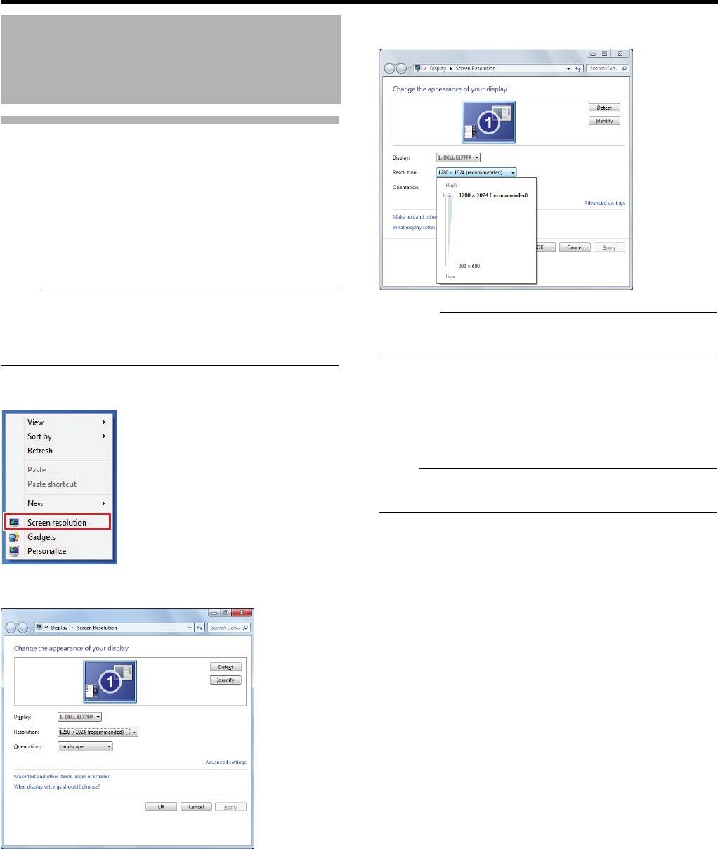
114
<Recorder Part> Reference
Changing the Monitor Resolution
This section describes procedures to change the resolution
of a display connected to this unit.
Recommended monitor resolutions are listed below:
●1024 x 768
●1280 x 768
●1280 x 1024
●1600 x 1200
●1920 x 1080
Note:
●Using a monitor with more than 1280 x 1024 resolution is
recommended.
●Some monitor resolutions may not be displayed
depending on the monitor connected.
1 Right-click on the desktop and select [Screen
resolution]
The [Change the appearance of your display] window
appears.
2
Click [Resolution] and drag the slider to select a
resolution.
Caution:
●If you attempt to set a resolution that is not supported by
the monitor, monitor synchronization may be interrupted.
3 Click [OK]
The preview is displayed.
4 Click [Keep changes]
The setting is changed.
Note:
●If no operations are made for 15 seconds, the setting is
reverted.
Changing the Monitor
Settings
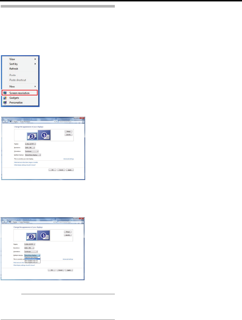
115
Establishing a Dual-monitor
Configuration
This section describes procedures to connect multiple
monitors to this unit and use them as one display.
●Connect multiple monitors to this unit in advance.
1 Right-click on the desktop and select [Screen
resolution]
The [Change the appearance of your display] window appears.
2
Drag a monitor in the [Change the appearance of
your display] window to align the main display (
1
)
and sub display (
2
) to their actual positions
3 Click the [Multiple displays] pull-down menu
and select [Extend these displays]
4 Click [OK]
Caution:
●When a dual-monitor configuration is used or the output
size is large, the load on the CPU will be increased. If the
CPU meter becomes red, reduce the load by, for example,
lowering the displaying or recording frame rate.
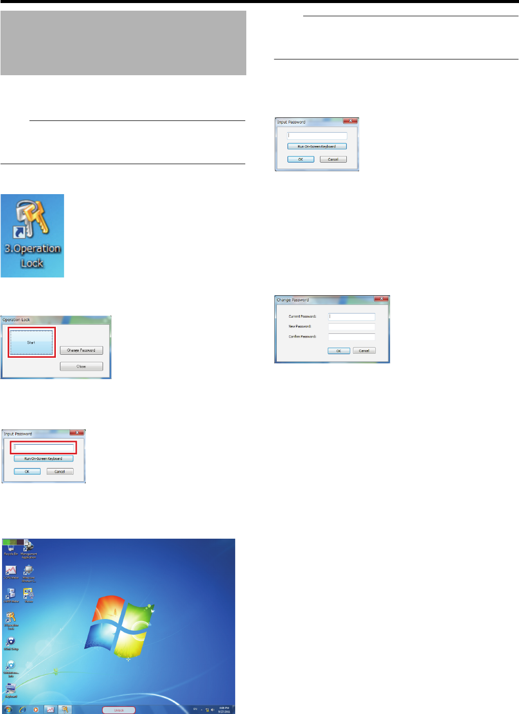
116
<Recorder Part> Reference
This unit is equipped with an operation lock feature to
prevent unintended shutting down by mistake.
Note:
●A password for locking or unlocking operation is not set at
the time of purchase. When no password is set, do not
enter anything.
1 Double-click [3. Operation Lock] on the desktop
The [Operation Lock] window appears.
2 Click [Start]
3 Enter the password
Click [Run On-Screen Keyboard] as necessary to enter
the password.
4 Click [OK]
Operations are locked and the [Unlock] button appears on
the desktop.
Note:
●When operations are locked, no operations other than
closing the on-screen keyboard or canceling operation
lock are available.
䡵To unlock operations
1 Double-click [Unlock] on the desktop
The password entry window appears.
2 Click [Run On-Screen Keyboard]
3 Enter the password and click [OK]
Operations are unlocked and you can perform operations.
䡵To change the password
1 Click [Change Password] in the [Operation
Lock] window
The [Change Password] window appears.
2 Enter the current password
3 Enter a new password
●Enter the password twice for confirmation.
4 Click [OK]
Locking Operations
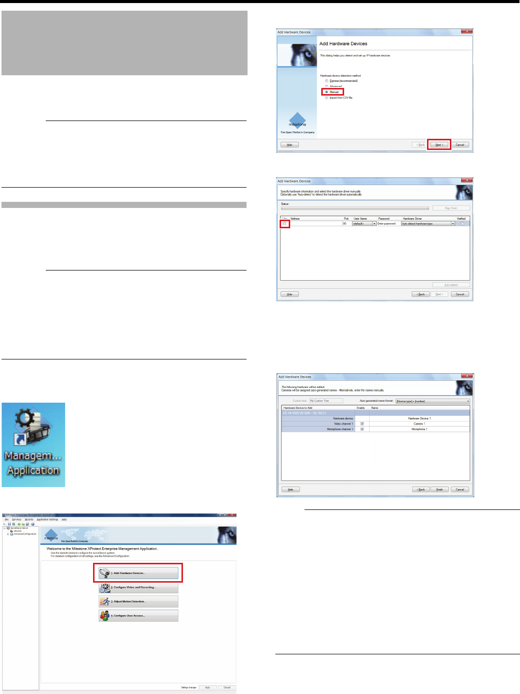
117
Even after configuring the system, you can add new cameras
and remove or replace registered cameras.
Caution:
●Never turn off the power while saving settings of
Management Application.
●When you change settings, restart the Management
Application service; otherwise, the new settings are not
applied.
Manually Registering a Camera
Cameras not automatically detected or newly installed
cameras may be registered on the system manually by
entering the IP address and port.
Caution:
●A user name and password is required for camera
registration. Be sure to confirm beforehand. For details,
see the instruction manual of the camera.
●Cameras with restricted user access may not be
registered. For more information about the access
restrictions, see the instruction manuals of the respective
cameras.
1 Double-click [Management Application] on the
desktop
2 Click [Add a Hardware Devices...]
3 Select [Manual] and click [Next]
4 Click [Use]
5 Enter the address, port number, user name, and
password for the camera to add and click [Next]
Camera verification starts.
When verification is complete, a summary of the added
camera (hardware device) appears.
Note:
●For the registered device, a name such as “Camera 1,”
“Camera 2,” etc. will be assigned names automatically
according to the device type (camera, microphone, etc.)
and the added order number. Click on a device name to
edit it.
●In the case that a camera cannot be verified, please
confirm the user name and password. If the user name for
the camera has been changed, it is possible to verify by
resetting the user name and selecting [default]. If it can
still not be registered, click [Back] and confirm whether the
driver for the camera is displayed on the pull-down menu
of [Hardware Drivers].
Changing the System
Configuration
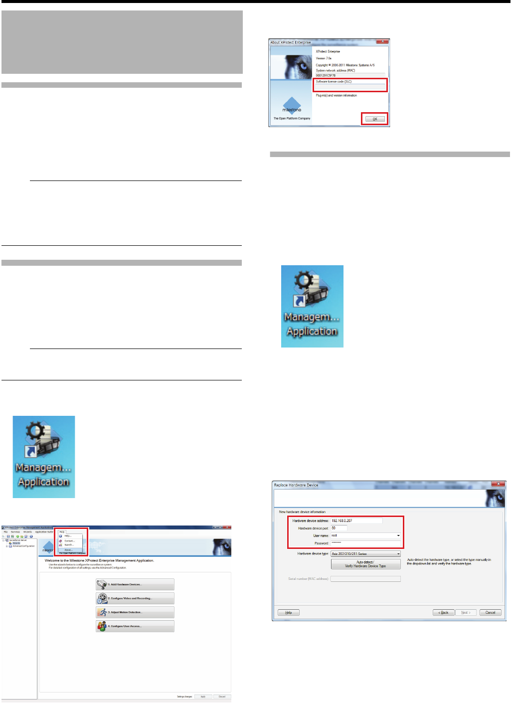
118
<Recorder Part> Reference
Manually Registering a Camera
(continued)
6 Click [Finish]
The camera has been added.
The added camera will be listed in “Hardware Devices” of
[Advanced Configuration].
Note:
●A camera can also be added by right clicking [Hardware
Devices] of [Advanced Configuration] and selecting [Add
New Hardware Device].
●Devices other than cameras (dedicated input/output
devices, etc.) can be added using the same procedure.
Adding a Camera License
To increase the registration allowance for NVR cameras,
purchase additional camera licenses and add them to this
unit. With additional licenses, up to 64 cameras (32
additional) can be registered for VR-X3200U, and up to 32
cameras (16 additional) can be registered for VR-X1600U.
Note:
●For purchasing additional licenses, consult your nearest
JVC KENWOOD dealer or service center.
1 Double-click [Management Application] on
desktop
2 Click [Help] and select [About...]
3 Enter the license code in the [Software license
code (SLC)] field, and click [OK]
If the code is valid, the number of licenses will appear.
Replacing a Hardware Device
This section describes procedures to replace a hardware
device currently used such as a camera with a new hardware
device.
●Use the [Replace Hardware…] wizard for configuration
after connecting a new hardware device.
1 Double-click [Management Application] on the
desktop
2 Click [+] in [Advanced Configuration]
3 Click [+] in [Hardware Devices]
4 Right-click the hardware device you want to
replace and select [Replace Hardware Device]
The wizard is launched.
5 Follow the instructions of the wizard to enter the
IP address, port number, user name, and the
password of the new hardware device
6
Select the driver for the new hardware device from
the [Hardware device type] list and click the [Auto
Detect/Device Type Confirmation] button
The driver is configured.
●If you click the [Auto Detect/Device Type] button without
selecting a driver, a necessary driver will be
automatically detected and configured.
7 Confirm the serial number (MAC address)
Changing the System
Configuration (continued)
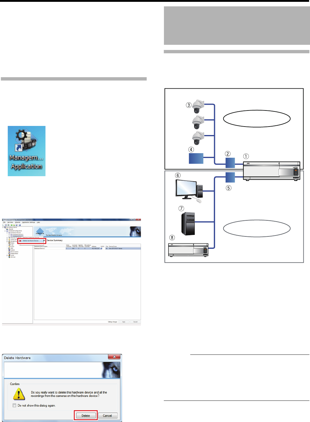
119
8 When replacing a camera, decide whether to
carry over the recorded images from the camera
There are three options.
●Take over recorded images: The new camera takes
over past image data.
●Discard past recorded images of the camera.
●Record new image data: Record new image data while
maintaining past image data.
9 Click [Finish]
Deleting a Hardware Device
This section describes how to delete an unused hardware
device such as a camera from the surveillance system.
1 Double-click [Management Application] on the
desktop
2 Click [+] in [Advanced Configuration]
3 Click [+] in [Hardware Devices]
4 Right-click the hardware device you want to
delete and select [Delete Hardware Device]
A confirmation message appears.
5 Click [Delete]
Proper Use of LAN1/LAN2
In this system, use LAN1 to connect to network cameras,
and LAN2 to connect to surveillance computers and the
timer server (NTP server).
AThis unit (master NVR)
BSwitching hub (LAN1)
CNetwork cameras
DNAS
ESwitching hub (LAN2)
FSurveillance computer
GTime server (NTP server)
HSlave NVR
Caution:
●LAN1 and LAN2 cannot communicate with each other. It
is not possible to configure settings of cameras connected
to LAN1 from a surveillance computer connected to
LAN2. Connect a computer for camera setup to LAN1 in
order to configure settings for cameras connected to
LAN1.
How to Use a Network
LAN2 : 192.168.1.xxx
LAN1 : 192.168.0.xxx
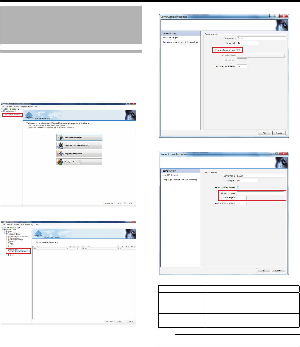
120
<Recorder Part> Reference
Performing Remote Monitoring
through WAN
This section describes settings for using the
monitoring service of this unit through the Internet.
1 Click [+] in [Advanced Configuration]
2
Right-click [Server Access], and select properties
The [Server Access Properties] window is displayed.
3 Select the [Enable internet access] check box
4 Set the internet address and internet port
Note:
●For more information, consult the network administrator.
5 Click [OK]
How to Use a Network
(continued)
Item Description
Internet address Set the global IP address or host
name for connecting to this unit
through the internet.
Internet port Set the port number for connecting to
this unit through the internet.

121
Defining a Recording Schedule
To set a recording schedule for a camera, create schedule
properties and apply them to the camera.
䡵Creating a Profile
1 Click [+] in [Advanced Configuration]
2 Double-click [Scheduling and Archiving]
[Scheduling and Archiving Properties] screen appears.
3 Click [Create...]
4 Click [Apply]
5 Select an item
6 Input the profile name, and click [Add New]
Changing the Recording
Settings
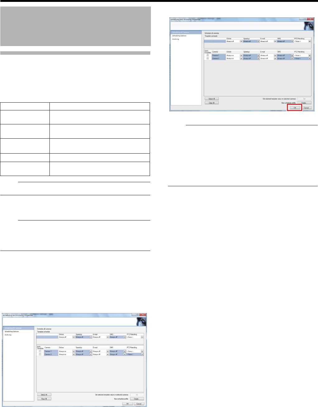
122
<Recorder Part> Reference
Defining a Recording Schedule
(continued)
7 Prepare a schedule
●For details of the setting items, see AScheduling Profile
Setting DescriptionsB (APage 123)
Note:
●This unit does not support notifications by SMS.
8 Click [OK]
The schedule profile is set.
Note:
●
To edit the name of a registered profile, select the profile to edit
from the "Schedule Profile: " list and click [Rename].
●To delete a registered profile, select the profile to delete
from the "Schedule Profile: " list and click [Delete].
䡵Applying a Scheduling Profile to a Camera
1 Click [+] in [Advanced Configuration]
2 Double-click [Scheduling and Archiving]
The schedules of the cameras in use appear.
3 Select the profile to apply for each item of the
camera you want to set
4 Click [OK]
The schedule of the camera is set.
Note:
●By selecting the [Apply template] check box to the left of
the camera name and clicking [Set], you can apply the
profile selected in [Template Schedule] to all selected
cameras at once.
●If you click [Select All], the check boxes of all cameras will
be selected.
●If you click [Clear All], the check boxes of all cameras will
be deselected.
Changing the Recording
Settings (continued)
Item Description
Online Period Duration in which images are received
from the camera
Speedup Duration in which speedup recording
is enabled
E-mail
Notification
Duration in which e-mail notification is
sent
SMS Notification
^
PTZ Patrolling Duration in which the PTZ camera
performs patrolling (APage 41)
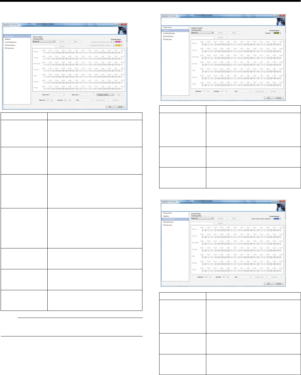
123
䡵Scheduling Profile Setting Descriptions
䢇Online Period
Note:
●If the event name for [Start event] or [Stop event] is too
long, it will not be displayed fully.
䢇Speedup
䢇E-mail Notification
Item Description
Set camera to
start/stop on
time
Select to set a period for which this
unit will constantly show images from
the camera. This is indicated by the
pink bar on the scheduling screen.
Set camera to
start/stop on
event
Select to display images at the
occurrence of the specified event. This
is indicated by the yellow bar on the
scheduling screen.
Start event/Stop
event
Select the event which brings the
camera online and the event which
takes in offline for when [Start up/shut
down the camera with an event] in
selected.
Start time/End
time/Day
Select the period (time/day) for which
the images from the camera are
displayed.
●You can also set the period by
dragging the mouse on the display
bar.
Set Period The period set by the [Start time] and
[End time] will be represented on the
bar display.
Change Period Adjust the period shown on the bar.
With the bar selected, enter and click
[Start time], [End time], and [Day].
Configure
Events
Select an event and click [Open]. The
setting screen of the selected event
will appear.
Item Description
Start time/End
time/Day
Select the period (time/day) for which
speedup recording is enabled.
●You can also set the period by
dragging the mouse on the display
bar.
Set Period The period set by the [Start time] and
[End time] will be represented on the
bar display.
Change Period Adjust the period shown on the bar.
With the bar selected, enter and click
[Start time], [End time], and [Day].
Item Description
Start time/End
time/Day
Select the period (time/day) for which
email notification is enabled.
●You can also set the period by
dragging the mouse on the display
bar.
Set Period The period set by the [Start time] and
[End time] will be represented on the
bar display.
Change Period Adjust the period shown on the bar.
With the bar selected, enter and click
[Start time], [End time], and [Day].
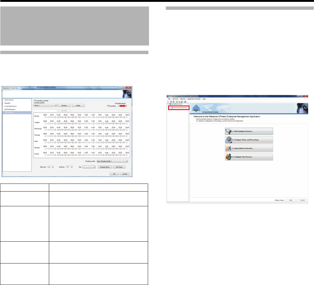
124
<Recorder Part> Reference
Defining a Recording Schedule
(continued)
䢇PTZ Patrolling
Setting Speech Communication
with Cameras
Settings for exchanging audio sounds between this unit and
cameras.
●You cannot send/receive audio sounds without a
microphone and a speaker for each camera.
●Some cameras follow the settings on camera side. If you
cannot send/receive audio sounds by configuring settings
of this unit, check the settings at the camera side.
1 Click [+] in [Advanced Configuration]
2 Click [+] in [Hardware Devices]
3 Right-click a camera you want to configure
settings for to display [Camera Properties]
4 Click [Audio]
5 Select a device for each of [Default
microphone:] and [Default speaker:]
6 Click [OK]
Changing the Recording
Settings (continued)
Item Description
Patrol profile Select the PTZ patrol profile to set the
schedule.
Start time/End
time/Day
Select the period (time/day) for which
the PTZ patrol profile is enabled.
●You can also set the period by
dragging the mouse on the display
bar.
Set Period The period set by the [Start time] and
[End time] will be represented on the
bar display.
Change Period Adjust the period shown on the bar.
With the bar selected, enter and click
[Start time], [End time], and [Day].
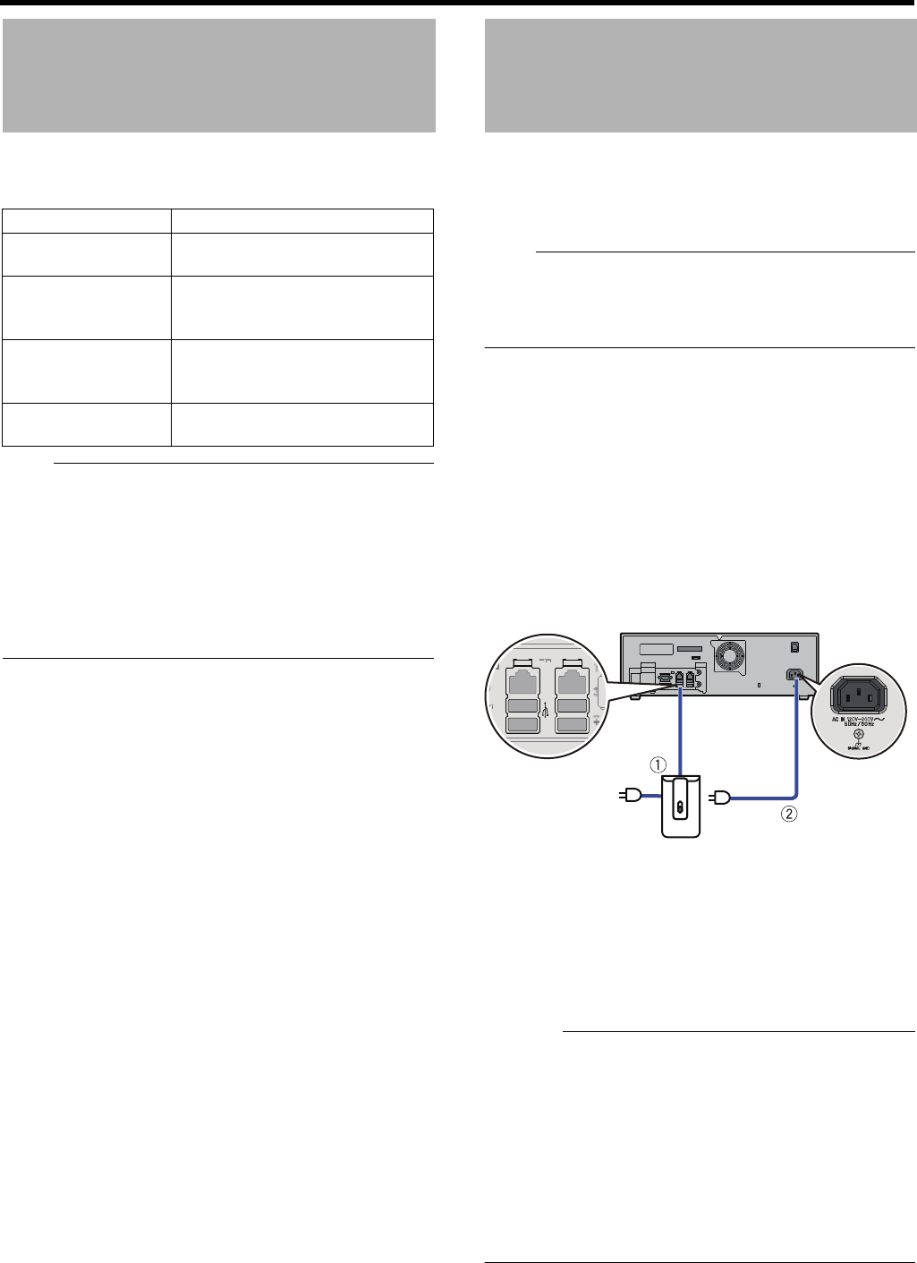
125
You may add the following drives as a storage destination for
recorded images, archiving, and export data.
Note:
●For details of compatible devices and additional HDD,
consult your nearest JVC KENWOOD dealer. You can
also check on our website.
●For formatting additional external HDD, see "When an
External HDD has been added" (APage 71).
●For setting NAS as the archive destination, see "Specify
NAS as the archiving destination" (APage 76).
●For building a RAID configuration using the built-in HDD,
see "Building a RAID Configuration" (APage 72).
Connecting a UPS (uninterruptible power supply) to the HDD
will protect it from damage by automatically shutting down all
operations prior to switching off the power supply in the event
of a power failure.
Note:
●For details of compatible UPS, consult you nearest JVC
KENWOOD dealer or service center. In some cases, a
UPS used with VR-N1600/VR-N900 series may not work
with this unit.
䡵Connection and setup
1 Set up the UPS.
●For details, refer to the instruction manual of the
device.
2 Press and hold down the [OPERATE] button for
about 2 seconds to shut down the system and
switch off the power switch on the rear panel
3 Connect a UPS communication cable to the
SERIAL terminal on the rear panel
4 Switch on the power of the UPS and then this
unit
Caution:
●Make sure that the UPS communication cable is
connected before switching on the power of this unit.
●Do not disconnect the communication cable when
operations are in progress.
●When a power failure occurs while formatting a HDD or
archiving, subsequent operations may be affected even
when a UPS is connected.
●The recorded images may not be played back properly if
they are not archived before the power failure.
●The connecting cable and settings vary depending on the
UPS used.
Adding a Drive
Type Connection method
DVD drive One of the SERIAL terminals on
the rear panel
External HDD A SERIAL terminal or eSATA
terminal on the rear panel
(APage 71)
Built-in HDD For details, consult our authorized
dealers or JVC KENWOOD
service centers.
NAS Network (LAN1) connection
(APage 75)
Using UPS
AUPS Connect to a SERIAL terminal
on the rear panel.
BSupplied power
cord
Connect the power cable of
this unit to the power outlet of
the UPS.
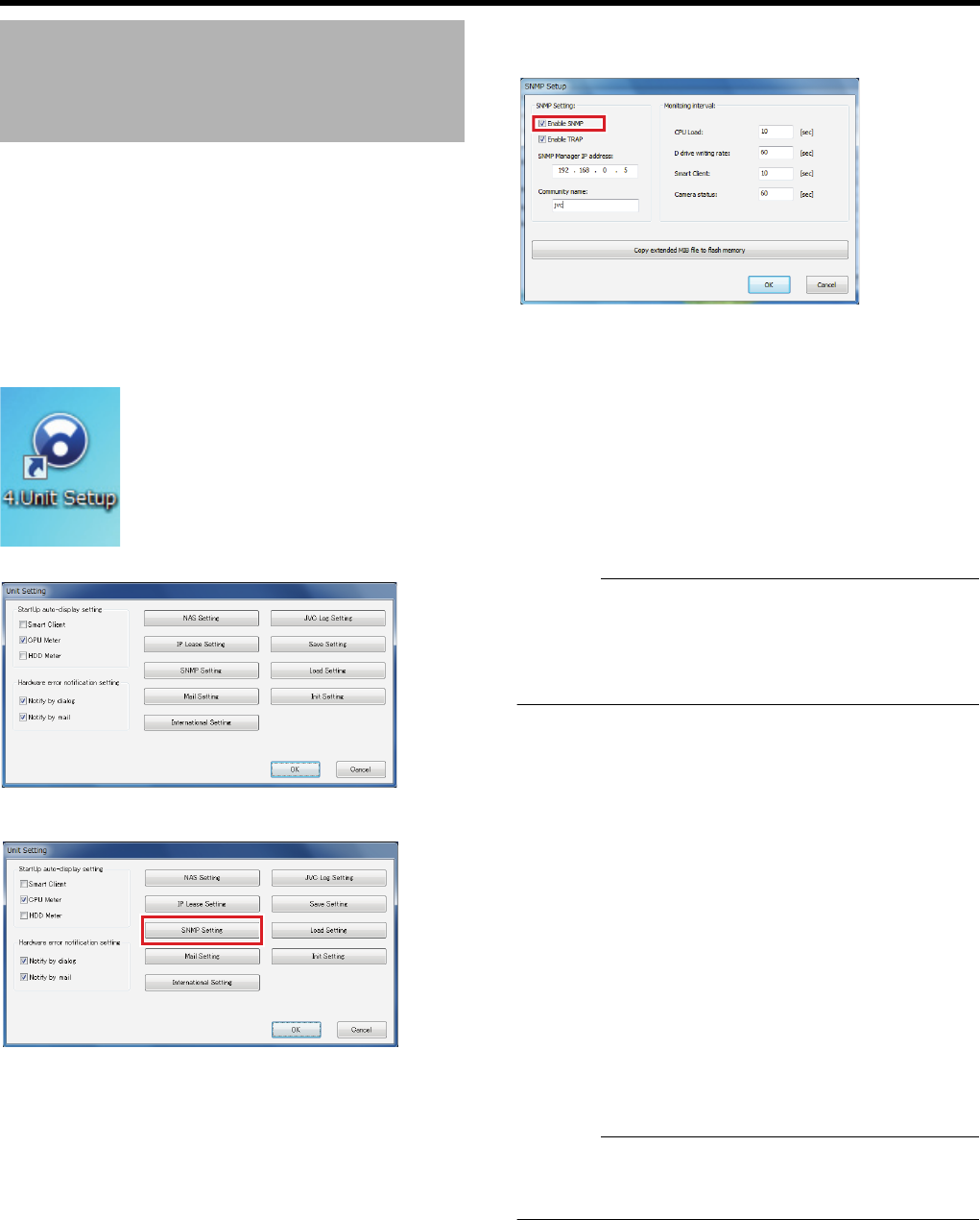
126
<Recorder Part> Reference
By enabling SNMP, you can monitor the status of this unit
from an SNMP manager on the surveillance computer. For
monitoring, you need to register MIB extension information
(JVCNVRMIB.txt) with the SNMP manager.
1 Insert a USB flash memory to the SERIAL
terminal
2 Double-click [4. Unit Setup] on the desktop
The [Unit Setting] window appears.
3 Click [SNMP Setting]
The [SNMP Setup] window appears.
4
Select the [Enable SNMP] check box in the
[SNMP Setting] section
●Select the [Enable TRAP] check box in the [SNMP
Setting] section to use TRAP.
●For TRAP notifications supported by this unit, refer to
"A list of TRAPs supported by this unit" (APage 127).
5 Enter the IP address of the surveillance
computer in the [SNMP Manager IP address]
field
6 Specify the SNMP community name
Example: kanshi1
Caution:
●You can use up to 32 characters for the community name.
●For TRAP, transmission may fail at the recipient side due
to its communication specifications. Use TRAP only as an
auxiliary measure and use polling judgment as a primary
measure.
7 Click [Copy extended MIB file to flash memory]
●The MIB extension information (JVCNVRMIB.txt) is
copied to a USB flash memory.
8 Resister the MIB extension information with the
SNMP manager on the surveillance computer
●For procedures to register the obtained MIB extension
information with the surveillance computer, refer to the
relevant instruction manuals of the SNMP manager.
9 Configure settings for monitoring (polling) by
the SNMP manager on the surveillance
computer
●For setup procedures, refer to the relevant instruction
manuals of the SNMP manager.
●For available statuses supported by this unit, refer to "A
list of statuses that can be obtained from this unit"
(APage 127).
Caution:
●To disconnect the USB device from the unit, be sure to
perform “remove” by right-clicking the target removal disk
on the explorer.
Setting SNMP

127
䡵A list of statuses that can be obtained from this unit
OID: iso(1) - org(3) - dod(6) - internet(1) - private(4) - enterprises(1) - jvc(718) - nvr(916) - nvrObjects(1)
䡵A list of TRAPs supported by this unit
OID: iso(1) - org(3) - dod(6) - internet(1) - private(4) - enterprises(1) - jvc(718) - nvr(916) - nvrTraps(2)
Group Identifier Name SYNTAX MAX-
ACCESS
UNITS Description
Current
value
nvrStausGroup
(1)
1 nvrRecStatus
INTEGER {
off(0),
on(1)
}
read-only - REC status
4 nvrCpuUsage INTEGER(0..100) read-only % CPU usage
5 nvrDdriveWrite INTEGER(0..
4294967295) read-only Byte/
Sec
Writing rate of D
drive
6 nvrRunViewer
INTEGER {
stop(0),
run(1)
}
read-only - Smart Client
executed status
Warning list nvrWarningGroup
(2)
1 nvrWarningTable SEQUENCE OF
NvrWarningEntry
not-
accessible -Table of last 10
warnings
1.1 nvrWarningEntry
NvrWarningEntry
INDEX {
nvrWarningIndex
}
not-
accessible -Table of last 10
warning entries
1.1.1 nvrWarningIndex INTEGER(1..10) read-only - Warning list index
1.1.2 nvrWarningDate DateAndTime read-only - Warning date and
time
1.1.3 nvrWarningInfo DisplayString read-only -Warning
information
Camera
List
nvrCameraGroup
(3)
1
nvrRegistCameraTable
SEQUENCE OF
NvrRegistCameraEntry
not-
accessible -
Table of 32
connected
cameras
1.1
nvrRegistCameraEntry
NvrRegistCameraEntry
INDEX {
nvrRegCamIndex
}
not-
accessible -
Table of 32
connected
camera entries
1.1.1 nvrRegCamIndex INTEGER(1..64) read-only - Connected
camera list index
1.1.2 nvrRegCamIpAddress IpAddress read-only -
Connected
camera IP
address
1.1.3 nvrRegCamName DisplayString read-only - Camera Name
1.1.4
nvrRegCamConnection
INTEGER {
disconnect(0),
connect(1)
}
read-only - Camera
connection status
Identifier Name OBJECTS STATUS Description
1 nvrRecStatusChange nvrRecStatus current REC status change notification
3 nvrNotifyWarning
nvrWarningIndex,
nvrWarningDate,
nvrWarningInfo
current Warning occurrence notification
4 nvrNotifyCamConnect
nvrRegCamIndex,
nvrRegCamIpAddress,
nvrRegCamName,
nvrRegCamConnection
current Camera connection status
change notification
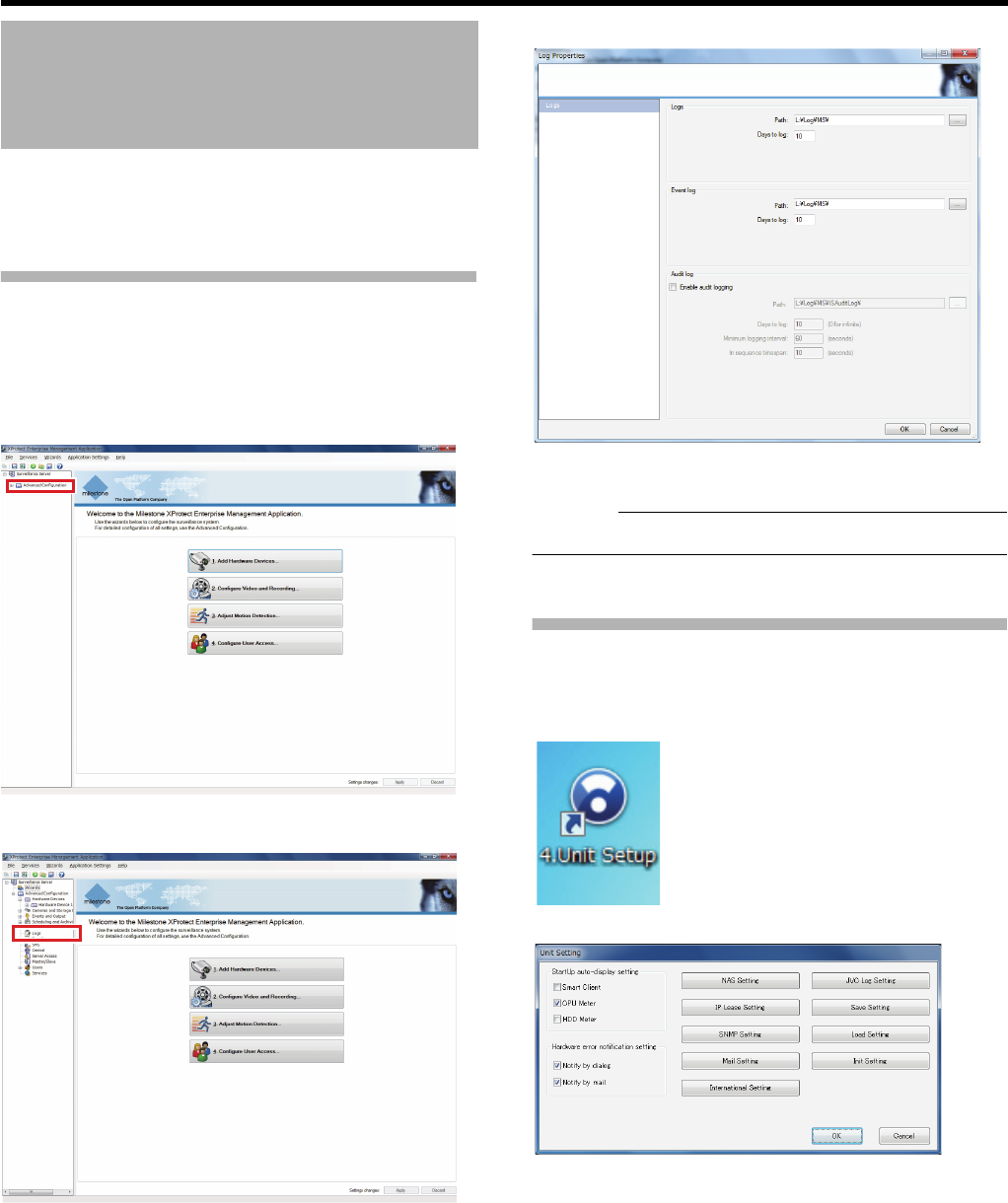
128
<Recorder Part> Reference
The logs for this unit are stored on the L drive.
Logs are used in the case of maintenance service.
Use 2 windows to configure log settings.
Changing the Log Storage Period
for Management Application
With the Management Application, 3 types of logs can be
saved: system logs, event logs and audit logs.
1 Click [+] in [Advanced Configuration]
2 Right-click [Logs] and select [Properties]
The [Log Properties] window appears.
3 Change the retention days
Caution:
●Do not change the destination.
4 Click [OK]
Changing the Log Storage Period
for the Unit Settings
1 Double-click [4. Unit Setup] on the desktop
The [Unit Setting] window appears.
Changing the Log Storage
Period
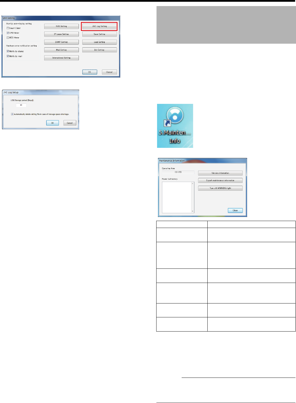
129
2 Click [JVC Log Setting]
The JVC log setting screen appears.
3 Specify the retention days
●Select this check box to delete unnecessary logs and
reduce the load on this device. Old logs will be deleted
automatically.
4 Click [OK]
You can save maintenance information on a USB flash
memory.
1 Connect a USB flash memory to a SERIAL
terminal on the front panel
2 Double-click [5. Maintenance Info] on the
desktop
The [Maintenance Information] screen appears.
3 Click [Export maintenance information]
4 Select a period and click [Export]
A folder called “NVR_Log” will be created on the USB
flash memory and the maintenance information and log
will be stored.
Caution:
●To disconnect the USB device from the unit, be sure to
perform “remove” by right-clicking the target removal disk
on the explorer.
Saving Maintenance
Information
Item Description
Operating time For displaying the runtime of this
unit.
Power fail history The power failure history
appears.The [Power fail history] is
empty if no power failure has
occurred in the past.
Version
information
For displaying the version
information of this unit.
Export
maintenance
information
For displaying the save maintenance
information screen.
Turn off WARNING
light
For turning off the WARNING light
on the front panel.
Close Closes the [Maintenance
Information] screen.
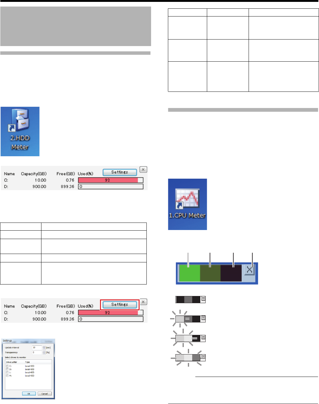
130
<Recorder Part> Reference
Checking HDD Usage
䡵Displaying the HDD meter
You can check the usage of HDD(s) of this unit with the
meter.
1 Double-click the [2. HDD Meter] on the desktop
The HDD meter appears.
䡵Changing HDD meter settings
You can specify the monitoring interval and HDD settings.
●Each drive is used for the purpose indicated below.
1 Click [Settings] in the HDD meter screen
2 Adjust the settings
3 Click [OK]
Checking the Load Factor of This
Unit
This unit is equipped with a CPU meter, so you can check
the load factor of this unit from the meter.
When the load factor increases, malfunctions such as failure
to record images at the specified frame rate may occur.
1 Double-click the [1. CPU Meter] on the desktop
The CPU meter appears.
Caution:
●When there is a red indication on the CPU meter,
decrease the load by, for example, lowering the
displaying/recording frame rate.
HDD Maintenance
Drive Purpose
CSystem disk
MFor saving temporary files of export
data.
LFor saving operation logs.
D or other
than the
above
For saving recorded images.
Item Preset Values Description
Update
interval
10 to 300
seconds
For specifying the update
interval in seconds.
Transparency
0 to 90% For specifying the
transparency of the HDD
meter.
Select
drives to
monitor
^Built-in HDD(s) and
recognized external
HDD(s) are listed.
Select HDD(s) to monitor.
Green Ye l l o w Red Close
Load factor below 5%: Grayed out
Load factor below 60%: Lighting up in green
Load factor below 90%: Lighting up in green
and yellow
Load factor over 90%: Lighting up in green,
yellow and red
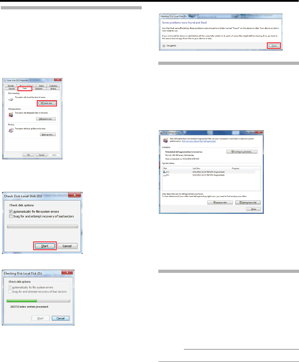
131
Performing Error Check
1 Click the [Start] button on the desktop and
select [Computer]
2 Right-click a drive to perform error check and
select [Properties]
The [Properties] screen of the drive you selected appears.
3 Click the [Tools] tab and click [Check now…]
The [Check Disk] screen of the drive you selected
appears.
4 Click [Start]
The error check starts.
Once the error check is completed, the result of the check
is shown.
5 Click [Close]
Performing Defragmentation
●Defragmentation may take several hours.
1 Click the [Start] button on the desktop, followed
by clicking [All Programs]
2 Click [Accessories] – [System Tools] – [Disk
Defragmenter]
The [Disk Defragmenter] window appears.
3 Right-click a drive to perform defragmentation
and click [Defragment disk]
Defragmentation of the selected drive starts.
●When the defragmentation is completed, current date
and time is displayed in the [Last Run] field.
4 Click [Close]
Initializing the Settings
Initialize the unit settings.
1 Double-click [4. Unit Setup] on the desktop
2 Click [Init Settings]
A confirmation message appears.
3 Click [Init]
4 Click [OK]
Caution:
●When the settings have been initialized, restart the unit.

Viewer Part
Basics
You can view live images and play back recorded images by using the viewer (Smart Client). This
chapter describes basic settings of the viewer and how to install the viewer to a surveillance
computer.
Caution:
●If you change settings of Management Application while Smart Client is on, shut down Smart Client, then restart it.
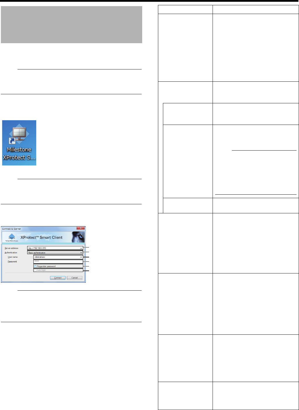
133
<Viewer Part> Basics
You can view live images and play back recorded images by
using the viewer (Smart Client).
Note:
●To use the Smart Client on a computer other than this
unit, make sure to install the Smart Client in advance.
(APage 136)
1 Double-click the Smart Client shortcut on the
desktop
The Smart Client login screen appears.
Note:
●If the Smart Client shortcut is not found on the desktop,
select ASmart ClientB from [All Programs] in the [Start]
menu.
2 Specify your login information in the following
fields
Note:
●Each of the default of the user name and password is set
as follows:
User Name: admin
Password: jvc
Starting Smart Client
1
2
3
4
5
6
Item Description
AServer address For specifying the IP address and
port number of this unit. (For
example, in the case of [http://
192.168.1.253:80], [:80] is the port
number.)
The port number is the number as
specified in [Advanced
Configuration] under [Server
Access] of the Management
Application. (APage 111)
BAuthentication For selecting one of the three types
of authentication.
Select [Basic authentication].
Windows
authentication
(current user)
Login as the current Windows user.
Windows
authentication
Login as the Windows user, but a
user name and password (MUST)
will be required.
Note:
●You will use this setting when
you login as the Windows user
to this unit from an outside
monitoring PC. You need to set
the login password for this unit
(APage 87).
Basic
authentication
A user name and password will be
required to login to this unit.
CUser name For entering the Windows user
name if you have selected
[Windows authentication] for the
[Authentication] in B (APage 87).
For entering the user name
registered in the [Users]
(APage 66) of the Management
Application if you have selected
[Basic authentication].
DPassword For entering the login password for
this unit if you have selected
[Windows authentication] for the
[Authentication] in B (APage 87).
For entering the password
registered in [User Setup]
(APage 66) of Management
Application if you have selected
[Basic authentication].
ERemember
password
If you have selected [Windows
authentication] or [Basic
authentication] for the
[Authentication] in
B
, select this
check box to login the next time
simply by clicking the [Connect]
button.
FAuto-login Enables you to login automatically.
Select this check box to
automatically login to the Smart
Client from the next time.
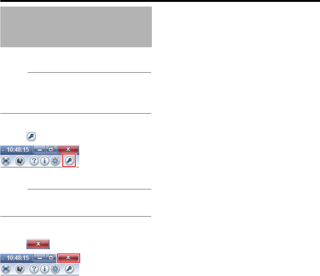
134
<Viewer Part> Basics
3 Click the [Connect] button
●The Smart Client screen appears after a short while.
Caution:
●When you log out after reaching the maximum number of
distribution clients, you may need to wait for several
minutes before you can establish the connection again.
●When multiple computers are connected and audio sound
is played back, the sound may be distorted.
䡵To log out
1 Click [ (Log Out)]
You are logged out and the Login screen of the Smart
Client appears again.
Caution:
●If you have restarted this unit, or the Smart Client on this
unit, log out from the Smart Client at the surveillance
computer, and login again.
䡵To finish
1 Click [ (Close)]
The Smart Client is closed.
Starting Smart Client
(continued)
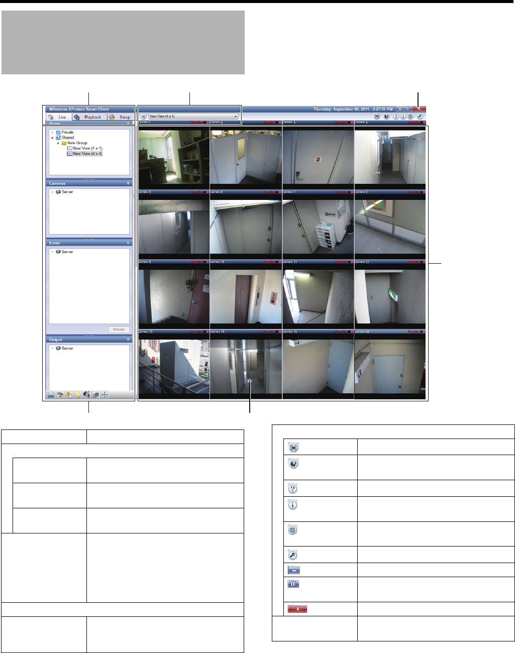
135
Viewer Description
4
1 6 5
32
Item Description
AScreen selector tabs
[Live] For viewing live images from
cameras. (A Page 142)
[Playback] For playing back recorded images.
(A Page 147)
[Setup] For displaying the viewer setting
screen. (A Page 139, Page 171)
BOperation
section
●The section to be displayed varies
depending on the current content
of the screen.
●Click any icon at the bottom of this
section to display the section you
want to use.
CCamera images
DView For viewing a split screen display of
images from multiple cameras. (A
Page 139)
EViewer operation buttons
(Full screen) For enlarging camera images.
(Notification
Dialog)
Display the status of the connected
server.
(Help) For displaying the help.
(About) For viewing information about the
Smart Client.
(Options) For confirming/changing settings of
the Smart Client.
(Log Out) For logging out.
(Minimize) For minimizing the window.
(Maximize/
Restore)
For maximizing the window.
(Close) For closing the Smart Client.
FView list For selecting one of the registered
views.

136
<Viewer Part> Basics
Note:
●The Smart Client logs in to a distribution server within the
VR-X3200U/VR-X1600U to operate.
●Embedded Smart Client also logs in to the distribution
server of this unit (http://localhost or http://127.0.0.1). By
default, it is configured to automatically log in to this unit.
For how to log in, refer to AStarting Smart ClientB
(APage 133).
●If surveillance computers of the maximum number of
clients are connected, you cannot log into the Smart
Client built into this unit.
Caution:
●If you have changed recording settings using the
Management Application, log out from the Smart Client
and then log in again. (APage 133)
●By default, you can log in to the system by just clicking
[Connect] in the [Connect to Server] screen.
When you have changed the settings, refer to descriptions
from Step 2 in the “Starting Smart Client” section
(APage 133).
●Even in the following situations, you may restore the
system by restarting the Smart Client:
●Live images and playback screen black out.
●Operations of the Smart Client are slow.
●The Smart Client is not responding.
●In the Smart Client, images and audio sounds may be out
of synchronization.
●If you have configured e-mail settings, conduct a test to
ensure that e-mails will be sent. (APage 110)
●If you have connected an additional HDD, startup may
take several minutes.
●Be sure to set the Smart Client so that the live frame rate
does not exceed the performance of this unit; otherwise,
the recording frame rate may decrease. For the
performance of this unit, see ARecording/Displaying live
images/Distribution performanceB (APage 196).
●Avoid continuous playback of recorded images (for longer
than 1 hour) as it may cause recording failure.
Installing the viewer (Smart Client) on a computer connected
to NVR and network will allow for:
●Viewing live images on the computer
●Controlling network cameras on the computer
●Viewing recorded images on the computer
Caution:
●Connect the computer to the LAN2 network.
●Settings for cameras connected to the LAN1 network
cannot be specified from a computer connected to the
LAN2 network.
Viewer Description
(continued)
Installing the Viewer on a
Computer

137
System Requirements Computer Network Settings
If using this unit with the factory default settings, set the
following computer network.
●For details, consult the network administrator. If using this
unit with settings different from the factory default
settings, confirm the setting with the network
administrator.
䡵Initial LAN2 Settings of This Unit
䡵Computer Settings
Caution:
●Do not use the same IP address in the same network
environment.
●Do not register multiple IP addresses with one NIC when
specifying the computer network settings.
Item Description
Operating
System
Microsoft Windows Server 2008 R1/R2
(32- or 64-bit*)
Windows Server 2003 (32- or 64-bit*)
Windows Vista Business (32- or 64-bit*)
Windows Vista Enterprise (32- or 64-bit*)
Windows Vista Ultimate (32- or 64-bit*)
Windows XP Professional (32- or 64-bit*)
Windows 7 Professional (32- or 64-bit*)
Windows 7 Enterprise (32- or 64-bit*)
Windows 7 Ultimate (32- or 64-bit*)
CPU Intel Core2 Duo or higher (Xeon for large
views) recommended, minimum 2.4 GHz
RAM Minimum 1 GB (more than 1 GB is
recommended for large screens)
Network Ethernet, 100 Mbps or higher
recommended
Graphics
Card
AGP or PCI-Express, minimum 1280 x
1024, 16-bit colors or higher
Hard Disk
Space
At least 100 MB free
Software Microsoft .NET 4.0 Framework and
DirectX 9.0 or later versions
Microsoft Internet Explorer 6.0
External address 192.168.1.253
Subnet mask 255.255.255.0
Default gateway 192.168.1.254
External address 192.168.1.11
Subnet mask 255.255.255.0
Default gateway 192.168.1.254
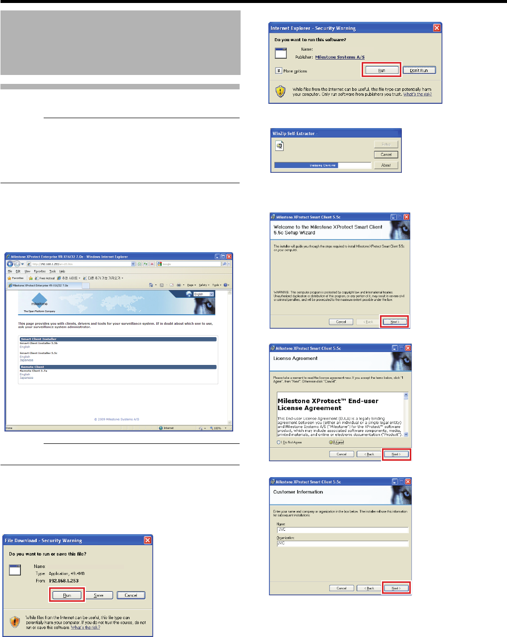
138
<Viewer Part> Basics
Installing the Smart Client
Caution:
●Before installing, check to ensure that Microsoft.NET
Framework 4.0, DirectX 9.0 or later versions, and
Microsoft Internet Explorer 6.0 or later versions are
already installed on the computer. If any of these are not
installed, installation of the Smart Client may fail.
1 Open the Internet Explorer browser (6.0 or later
versions), and enter the IP address of NVR as
Ahttp://192.168.1.253B
A welcome page will appear.
Caution:
●Do not select [Remote Client].
2 Click [(Smart Client Installer) English]
The [Do you want to run or save this files?] confirmation
message appears.
3 Click [Run].
Confirmation message appears, asking “Do you want to
run this software?”.
4 Click [Run].
Doing so starts up the Smart Client Setup Wizard.
5 Click [Next] and follow the installation
instructions
Installing the Viewer on a
Computer (continued)
NVR Viewer
NVR Viewer をこのPCにインストールします。
NVR Viewer.exe
NVR Viewer Installer
NVR_Viewer [1].exe
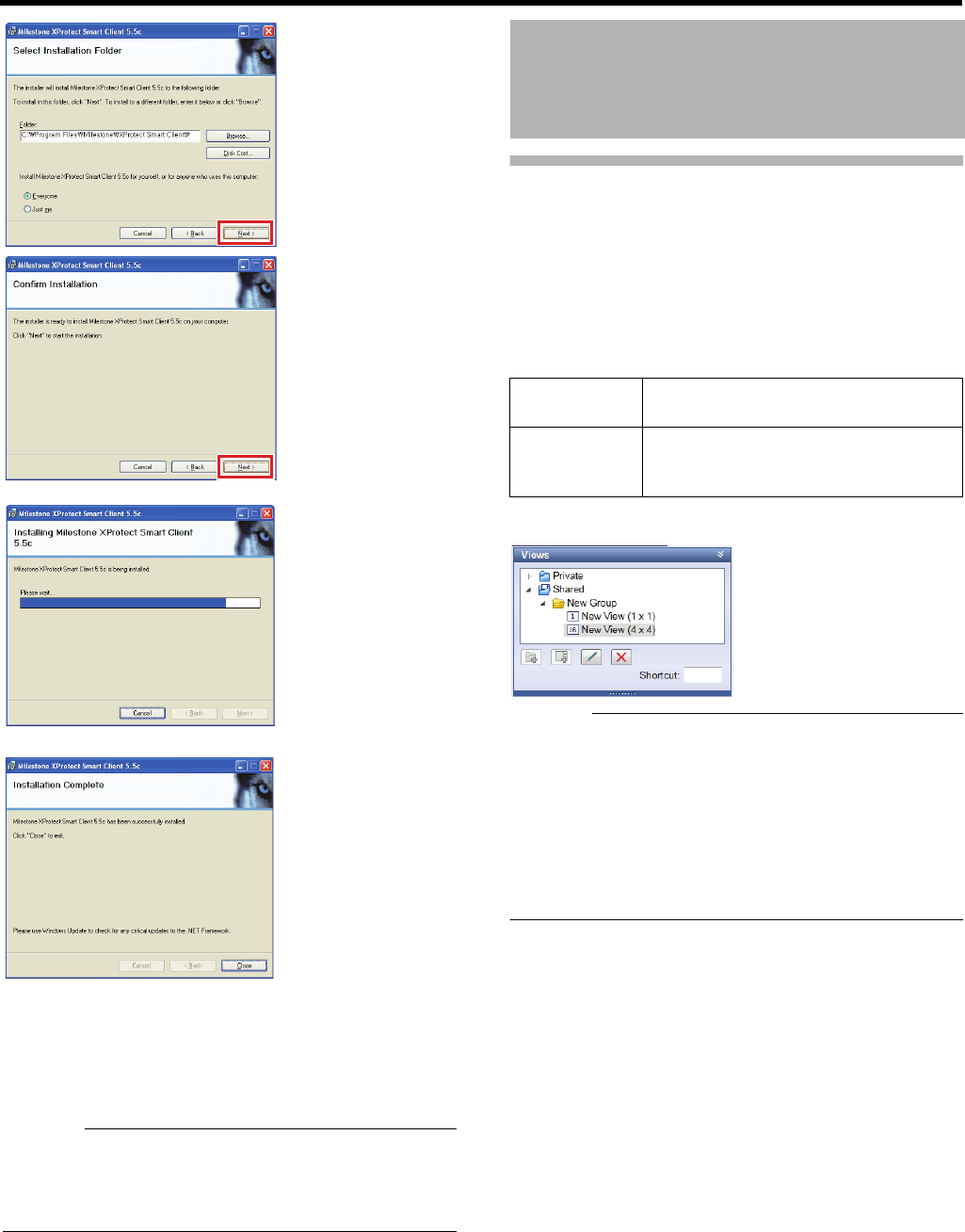
139
6 Click [Close]
Installation ends and a shortcut to the ASmart ClientB is
created on the desktop.
Caution:
●If the .Net Framework 4.0 installation window is displayed
during installation and the computer is not connected to
the internet, it may not be possible to continue with the
installation.
Groups and Views
Split screen display of images from multiple cameras in the
Smart Client is called “view.” Any number of views can be
created in accordance with camera locations and quantity
and managed by groups (folders).
䡵Group and view structure
The following 2 groups are preset as root groups for groups
you will create.
●You can check the group and view structure from the
[Views] section.
Caution:
●Select [Basic Authentication] for the authentication
method. Enter the user name and password of the basic
user. For details of the default registered basic user, see
AUsersB (APage 112).
●The [View group saving error] dialog may appear when
you attempt to change views in the shared folder. In this
case, click [OK] to close the error dialog and log out from
the Smart Client (APage 134). Then log in to the system
again to try to change views again.
Creating a View
Private Views in this folder are only accessible to
the user who created them.
Shared Views in this folder are accessible to all
computer users who can access the
system.
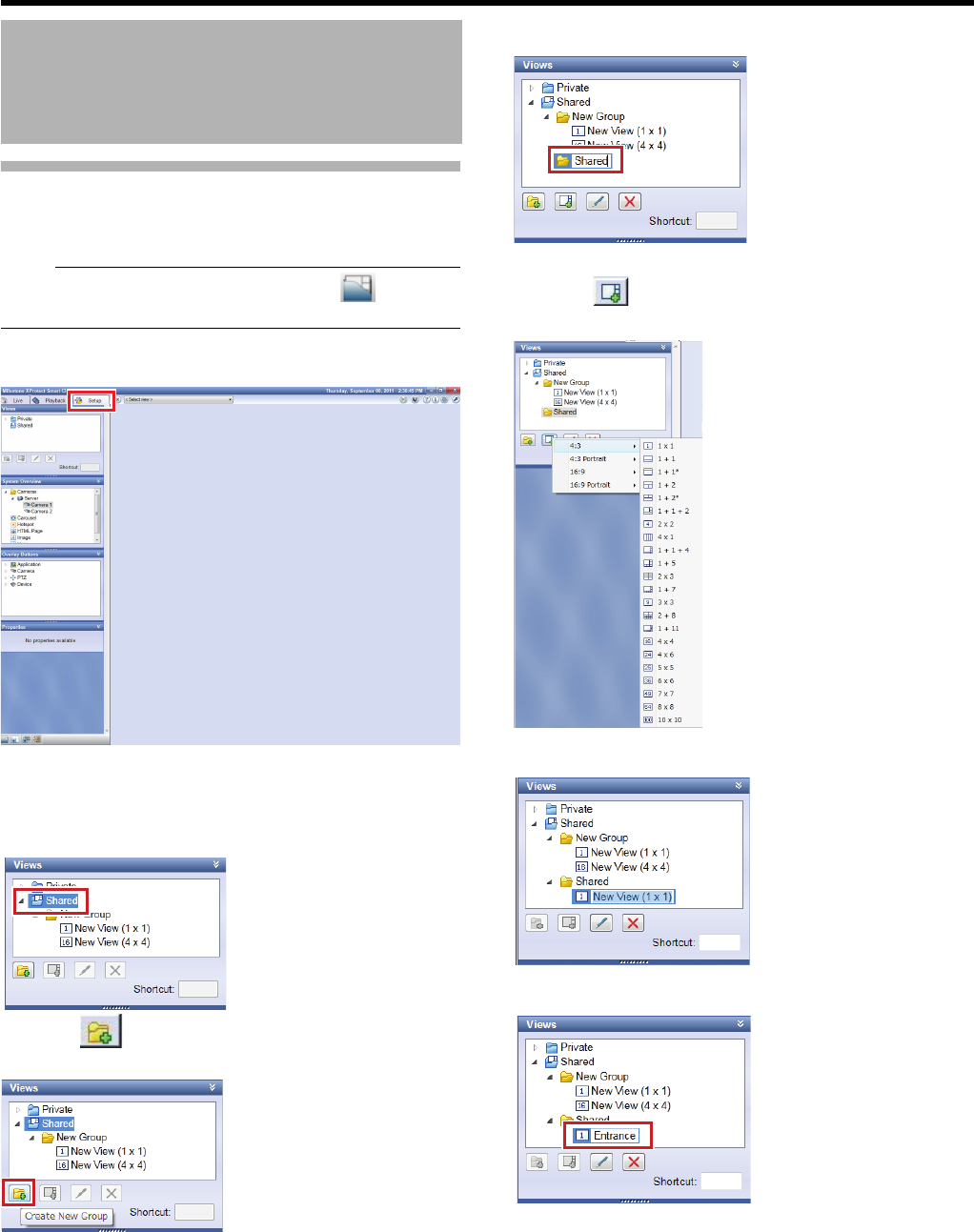
140
<Viewer Part> Basics
Creating a View
To create a view, you need to create a group first and
registers a camera to show in the view.
Note:
●If the [View] section is not displayed, click [ ] to display
it.
1 Click the [Setup] tab
2 In the [Views] section, select a root folder
(Private or Shared) you want to create a new
group in
3 Click [ (Create New Group)]
A new group is created.
4 Enter a group name for the new group
Then, create a new view in the group you just created.
5 Click [ (Create New View)] and select a
layout for a new view
A new view is created in the group.
6 Enter a view name
Next, register the camera to display the created view.
Creating a View
(continued)
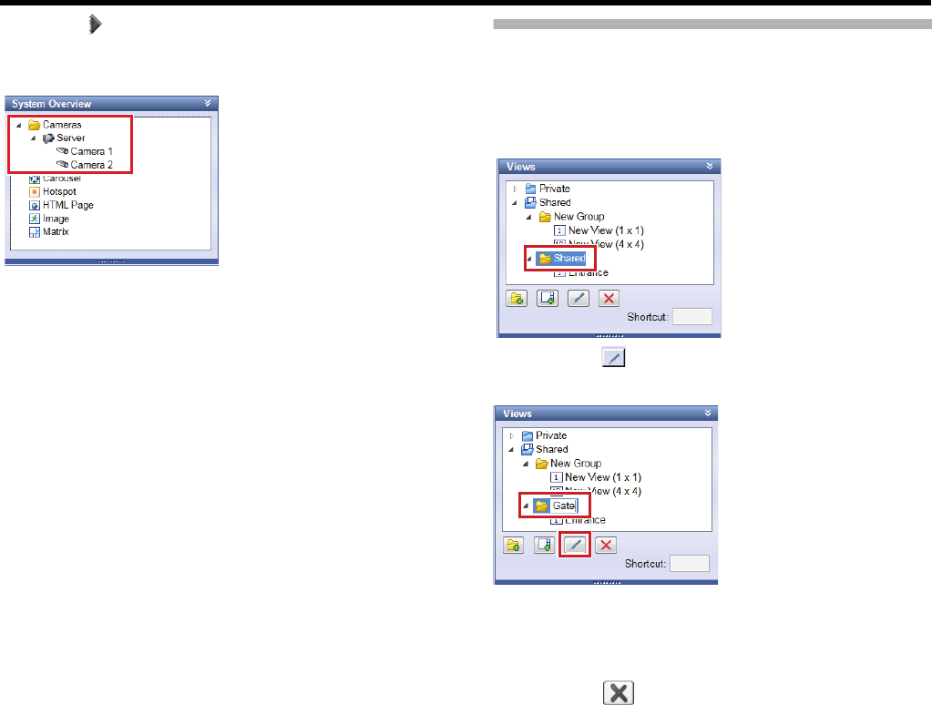
141
7
Click [ ] to the left of [Server] in the [System
Overview] section
A list of available cameras appears.
8 Select a camera you want to view from the list
and drag it onto the image display screen to the
right
●Images from the selected camera are displayed along
with its camera name.
●Repeat the same steps for each camera.
Editing Views
䡵Changing a group/view name
1 Select a group/view you want to change the
name for in the [Views] section
2 Click the [ (Rename)] button and enter a
group/view name
䡵Deleting a group/view
1 Select a group/view you want to delete in the
[Views] section
2 Click the [ (Delete)] button
A confirmation message prompts you to confirm you want
to delete the selected group and all views in the group, or
selected views.
3 Click [Yes]
䡵Remove the camera from the view
1 Click [×] in the upper right of the camera window
to remove
The camera is removed from the view.
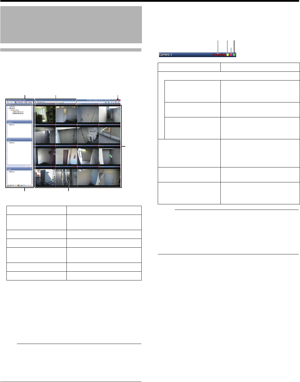
142
<Viewer Part> Basics
Showing the Live Window
1 Click the [Live] tab
The live window appears.
●If you configure camera recording settings without closing
the live window, live images may not be displayed
correctly after you configure the camera recording
settings.
In this case, “Cannot connect to server! Retry” or “Cannot
connect to 127.0.0.1:80 on [device name] (camera name)”
will be displayed in the live screen. (127.0.0.1:80 is an
internal IP address of this unit during operations.)
Note:
●It may take a while to show images from cameras
depending on the network line status.
●It may take several minutes to show the live image display
screen depending upon the number of additional HDD(s)
connected.
䡵To check the camera status
Check the status from the 3 color box indicators and the
characters that indicate camera operation status on the blue
bar at the top of the window of each camera.
Note:
●To enlarge the camera window, double-click the upper
blue bar. To restore the original size, double-click the
upper blue bar again.
●Click the active event or motion indicator to turn off the
indicator. You can hide the live indicator in "Display
settings" (APage 172)
Viewing Live Images
Item Description
A[Live] tab For displaying the Live
window.
BOperation section (APage 143)
CCamera images Live images from the camera
DView Segmented display of images
from multiple cameras
E[Close] button For closing the Smart Client.
FView list For switching views.
4
1 6
3
2
5
Item Description
ACamera operation status indications
Live (green) For indicating that live images
are being displayed without
recording.
Recording (red) For indicating that images are
being recorded.
Stopped (yellow) For indicating that images
cannot be acquired form the
camera or the camera is offline.
BEvent indicator
(left: yellow)
Turned on when any event
occurs. If no event is specified
or exists, the indicator remains
in black.
CMotion indicator
(center: red)
Turned on when any motion is
detected.
DLive indicator
(right indicator:
green)
Blinking each time it receives
images from the camera.
1 2
3
4
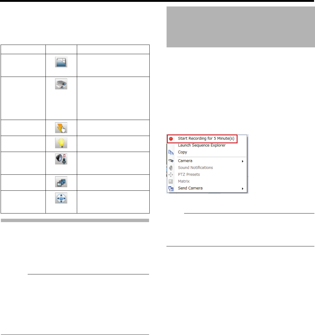
143
䡵Operation section on the live screen
In the live image screen, you may use the following
operations in corresponding sections.
●You can select to show/hide each section by clicking an
icon.
Switching Views
This section describes procedures to switch views and
display images from another camera.
1 Select a view in the [Views] section, or from the
view list on the upper part of the window
Caution:
●Do not switch views frequently in a short time.
●If live images are not displayed in VN-C625U/VN-C655U,
change the password for VN-C625U/VN-C655U
connection set in the camera and this unit. For setup
procedures, refer to the relevant instruction manuals of
cameras used, and the [Password] setup procedures
under [Hardware Devices] in [Advanced Configuration]
described in this manual (APage 92).
You can record images of a specific camera when you view
live images.
●Access to this feature is limited. For details, please
contact your monitoring system administrator.
●You need to set an upper limit of recording time in the
Management Application in advance. (“Manual
Recording” (APage 101)
1 Right-click on a camera image you want to
record and select [Start Recording…] from the
shortcut menu
Recording starts and will automatically end after the
specified time.
Note:
●You cannot stop recording while it is in progress.
●You cannot change the recording time from the Smart
Client. For details, please contact your monitoring system
administrator.
Section name Icon Operation
Views For selecting a view to
display from the registered
views.
Cameras For displaying a camera
list. By selecting a camera
not listed in the view and
drag it into the view, you
can view images from the
camera.
Event For manually triggering a
preset event.
Output For performing a preset
output.
Audio For using a microphone or
a speaker connected to the
camera.
Sequence
Explorer
For displaying a list of
recorded images.
PTZ Control For performing camera
operations (pan, tilt and
zoom).
Manually Recording
Images of a Specific
Camera
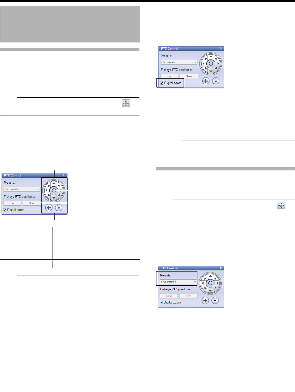
144
<Viewer Part> Basics
Viewing Images by Using PTZ
Features
PTZ (pan, tilt and zoom) operations are available only when
the camera supports the PTZ features.
●Button operations are ignored when the camera does not
support the PTZ features.
Note:
●If the [PTZ Control] section is not displayed, click [ ] to
display it.
1 Click the top bar of the live screen of a camera
you want to select, and select the camera
●When you select a camera, the blue top bar turns to
light blue.
2 Click the PTZ navigation buttons in the [PTZ
Control] section
Note:
●When the mouse pointer turns to a crosshair point on the
PTZ camera image screen, you may change the direction
of the camera by pointing and clicking the image screen. If
it does not, you cannot perform camera operations on the
image screen. For some PTZ cameras, the mouse pointer
may not turn to a crosshair pointer. Moreover, operations
may not be available even when the mouse pointer turns
to a crosshair pointer, depending on the type of PTZ
camera. In these cases, perform operations by using the
PTZ navigation buttons in the [PTZ Control] section.
●For any analog camera connected to a network encoder
(IP video server: VN-E4U/E, etc.) the pointer does not
turn to a crosshair pointer.
●With a mouse with a scroll wheel, you can use the wheel
to zoom in/out with a PTZ camera.
●If you use the electronic zoom feature of VN-V685U/VN-
V686U/VN-V686BU Series, the electronic zoom
operations stop temporarily on the boundary between the
optic zoom and electronic zoom. To continue zooming,
perform the zoom operation again.
䡵Digital zoom
You can view enlarged images from cameras by selecting the
[Digital zoom] check box in the [PTZ Control] section.
Performing the digital zoom operation will show a small view
of the whole image at the lower right.
Note:
●Images to be recorded are not zoomed even when digital
zoom is used.
●When digital zoom is used, the recording frame rate may
decrease due to increased load on this unit.
●Deselect the [Digital zoom] check box to finish digital
zoom.
Caution:
●When the [Digital zoom] check box is selected, actual PTZ
operations are not performed.
Using the Preset Features
By selecting from the preset list, you can move the camera
direction to the preset position.
Note:
●If the [PTZ Control] section is not displayed, click [ ] to
display it.
●This operation is available only when the camera supports
the PTZ features.
●The preset list can be configured from [Advanced
Configuration] B [Hardware Devices] B (PTZ camera’s)
[Camera Properties] B [PTZ Preset Positions] in the
Management Application. (APage 39)
1 Select a preset position from the preset list in
the [PTZ Control] section
●The camera moves to the preset position.
Operating Cameras on the
Live Image Screen
Item Description
APTZ navigation
buttons
For moving the camera in the
direction of arrows.
BHome button For returning to the home position.
C[+]/[-] For zooming in/out.
1
3
2
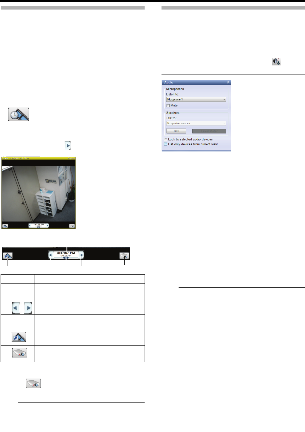
145
Playing Back Recorded Images for
Specific Camera(s) (Independent
Playback)
In the [Live] tab, you can view live images of all cameras.
By using the independent playback function, you can switch
to view past recorded images on specific camera(s) only.
●Independent playback function can be used for multiple
cameras.
●Independent playback function can also be performed
from the view in the [Playback] tab.
1 Point the cursor to camera images in the view
The independent playback start button appears on the
camera images.
2 Click the independent playback start button
The camera’s title bar turns yellow and playback pauses.
To start playback, click [ ] to the right of the time and
date display.
3 Search for images you want to view
●The controller disappears when the cursor goes out of
the camera images.
4 Click [ ] to finish independent playback
The color of the title bar returns to normal.
Note:
●If the camera window is displayed small, the slider is not
displayed. In this case, display the slider by maximizing
the Viewer or double-clicking the bar on the upper edge of
the camera window to enlarge it.
Other Useful Features
䡵Speech communication
A speech communication feature is available from the [Audio]
section with a microphone or a speaker is installed to the
camera.
Note:
●If the [Audio] section is not displayed, click [ ] to
display it.
To hear audio sounds from a microphone installed to the
camera, select the microphone from the [Listen to] list.
●Select the [Mute] check box to temporarily mute the
microphones.
To talk to the other party through a speaker installed to the
camera, select the speaker from the [Talk to] list. Select [All
Speakers] to talk to all speakers at the same time.
●During talking, keep [Talk] clicked.
●Talker’s volume level can be checked from the level meter.
Caution:
●Audio sounds may be interrupted when more than one
surveillance computer listen to the sounds.
●When you return from the setting screen to the live image
display screen, the microphone and/or speaker are
deselected. Select them again if necessary.
●If the network is congested, audio sounds may not be
transmitted.
Note:
●If any camera for which an audio source is specified in
[Audio] under [Camera Properties] of [Hardware Devices]
is selected, the specified audio sounds are output.
(APage 95)
●If you select the [Lock to selected audio devices] check
box, the current microphone and/or speaker will remain
selected when you select another camera with a
microphone and/or speaker.
●Select the [List only devices from current view] check box
to list the audio devices in the view only.
●If any camera for which an audio source is specified is
selected, the last audio sound output will be used
continuously.
●When live images are displayed at the same time as
recording, images and sounds may be out of
synchronization. (This does not affect recording to this
unit of additional HDD.)
Item Description
ATime
and date
For displaying the date and time when the
image was recorded.
B
For reverse/normal playback
●
Click once to use them as pause buttons.
CSlider
For changing playback speed during playback.
●Audio sounds will not be played back.
DFor switching to the playback view at the
time of the present recorded image.
EFor finishing independent playback.
1
3
225
4
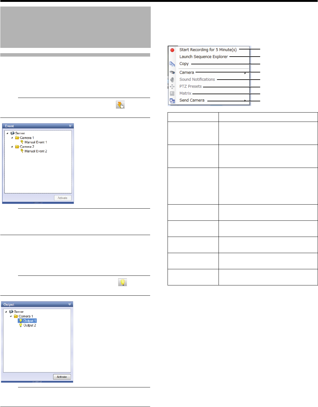
146
<Viewer Part> Basics
Other Useful Features (continued)
䡵Manual events
You can trigger an event manually. Select an event in the
[Event] section and click [Activate].
Note:
●If the [Event] section is not displayed, click [ ] to
display it.
Note:
●For events, refer to "Events and Actions" (APage 46).
●You need to set an event in advance. (APage 50 "Event
Configuration—Manual Event")
䡵Output control
This feature provides a preset output such as lighting on/off
and siren, etc. Select an output in the [Output] section and
click [Activate].
Note:
●If the [Output] section is not displayed, click [ ] to
display it.
Note:
●You need to set an output in advance.
(APage 56 "Action Setup—Output")
䡵Camera shortcut menu
You can open the shortcut menu by right-clicking on the
camera image screen.
●The menu items may differ according to the camera
settings.
Operating Cameras on the
Live Image Screen
(continued)
Item Description
AStart
recording
for...
For starting recording with the
selected camera (manual recording).
BLaunch
Sequence
Explorer
For launching the Sequence Explorer
of the selected camera.
CCopy Copy the image from the selected
camera as a still picture. The copied
still picture can be pasted into other
applications (word processing
software, etc.) as a bitmap file.
DCamera For displaying images of other camera
in the selected position.
ESound
Notifications
For muting warning sound, etc.
temporarily.
FPTZ Presets For selecting a preset position and
moving the camera.
GMatrix Manually distribute images using
Matrix.
HSend Camera For displaying images of the selected
camera in the specified window.
2
3
7
5
4
8
6
1
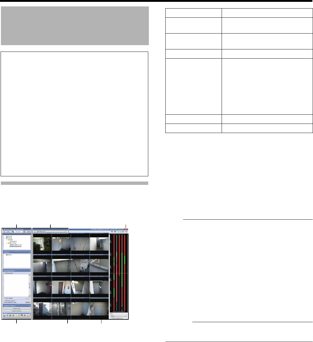
147
Displaying the Playback Screen
1 Click the [Playback] tab
The playback screen appears (it may take several minutes).
●If you configure camera recording settings when the
playback screen is active, playback images may not be
displayed correctly after you configure the camera
recording settings.
In this case, ACannot connect to server! RetryB or
ACannot connect to 127.0.0.1:80 on [device name]
(camera name)B will be displayed in the playback
screen. (127.0.0.1:80 is an IP address of this unit
during operations.)
●If you attempt to play back when there are no recorded
images, the playback screen keeps showing AConnect:
[NVR] Camera1 on 127.0.0.1:80B.
Note:
●The live indicator appears in the top bar of the playback
screen. It lights up in green each time new images are
displayed.
●Recorded images are saved as a database. Recording
data is called a database in this unit.
●If a message such as “Before database start” is displayed
in the playback screen, there is no database (recorded
images) before the current position.
●If a message such as “No data” is displayed in the
playback screen, there is no database (recorded images)
after the current position.
●If the timeline is not displayed correctly (for example, it is
split), switch the screen by clicking the [Live] or [Playback]
tab, then click the [Setup] tab again.
Caution:
●Do not switch between the live screen and the playback
screen frequently in a short time.
Viewing Recorded Images
Notes:
●The recording frame rate may decrease during
operations in the playback screen.
●When there is frequent access to the HDD, i.e. recorded
images are played back at the same time with
recording, playback images or audio sounds may be
interrupted. (This does not affect recording to this unit of
additional HDD.)
●When returning to the playback screen from the setting
screen, the microphone selection for the [Audio] section
may return to [None]. Reselect the microphone.
●Use the same time zone for the computer and this unit.
When you play back recorded images on a computer
with different time zone, the time of recorded images of
this unit will be converted to the computer’s time zone.
●If you want to change the time zone from date and time
settings, click the [×] button to exit the Smart Client and
restart.
1 6 5
2 43
Item Description
A[Playback] tab For displaying the [Playback]
screen.
BOperation
section
(APage 148)
CCamera images Recorded images from the camera
DView Segmented display of recorded
images from multiple cameras
●Recorded images of the same
time and date (the time and date
displayed in the [Time
Navigation] section) are
displayed for all cameras in the
view.
E[Close] button For closing the view.
FView list For switching views.
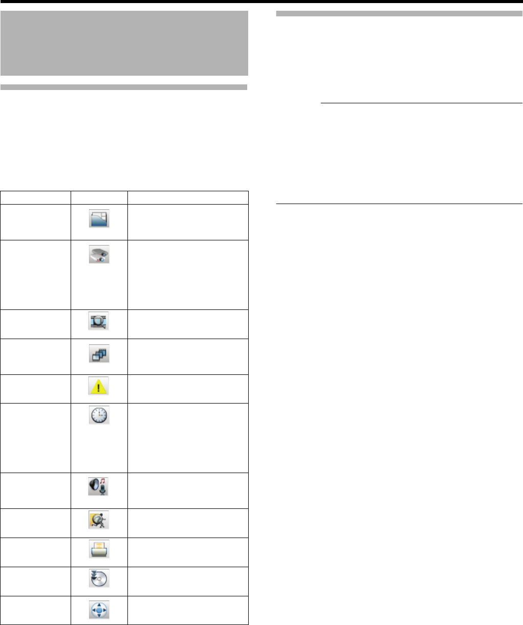
148
<Viewer Part> Basics
Displaying the Playback Screen
(continued)
䡵Operation section on the playback screen
In the playback screen, you may use the following operations
in corresponding sections.
●You can select to show/hide each section by clicking an
icon.
Switching Views
This section describes procedures to switch views to show
images of other cameras.
1 Select a view in the [Views] section, or from the
view list on the upper part of the window
Caution:
●Do not switch views frequently in a short time.
●If live images are not displayed in VN-C625U/VN-C655U,
change the password for VN-C625U/VN-C655U
connection set on the camera and this unit. For setup
procedures, refer to the relevant instruction manuals of
cameras used, and the [Password] setup procedures
under [Hardware Devices] in [Advanced Configuration]
described in this manual (APage 92).
Viewing Recorded Images
(continued)
Section Icon Description
Views For selecting a view to
display from the registered
views.
Cameras For displaying a camera
list. By selecting a camera
not listed in the view and
dragging it into the view,
you can view images from
the camera.
Recording
Search
For searching for recorded
images by sequences.
Sequence
Explorer
For displaying a list of
sequence images of all
cameras in the view.
Alerts For searching for recorded
images by alerts.
Time
Navigation
For searching for recorded
images by specifying date
and time, as well as for
performing playback
operations for recorded
images.
Audio For performing speech
communication with
camera(s).
Smart Search For searching for images
with any motion.
Print For printing recorded
images.
Export For saving recorded images
on the desktop, etc.
PTZ Control For performing PTZ camera
operations.
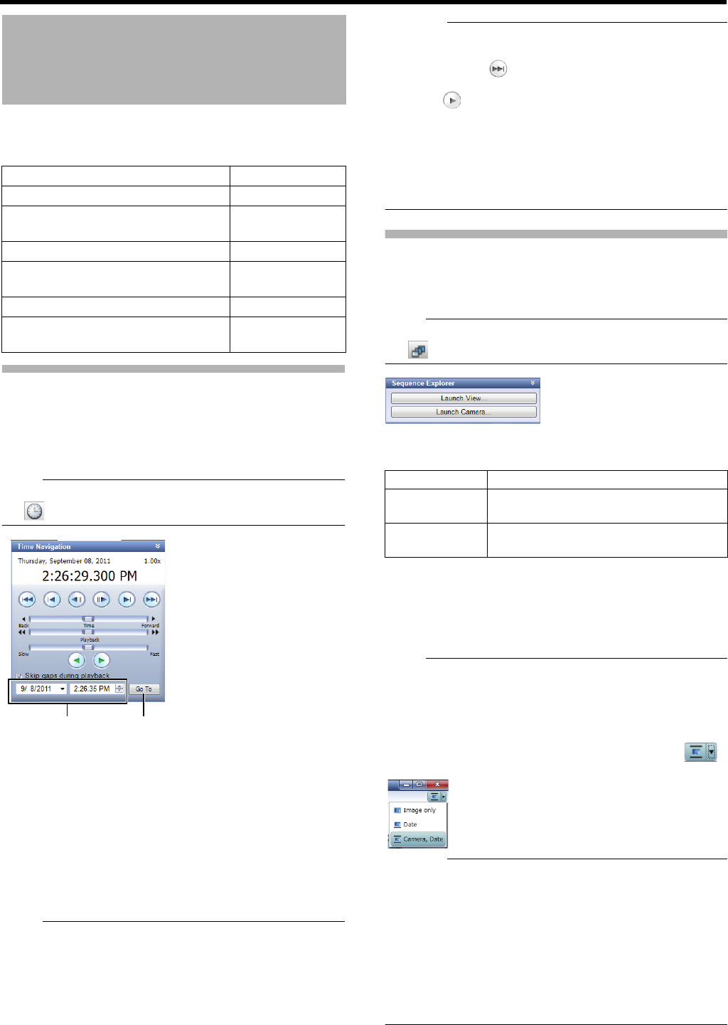
149
You can search for images recorded by this unit in following
ways.
Search for recorded images by date
and time
This section describes procedures to search for recorded
images by using the [Time Navigation] section in the
playback screen.
Note:
●If the [Time Navigation] section is not displayed, click
[ ] to display it.
1 Select a search date and time in the [Time
Navigation] section
●Specify a date and time in the left and right boxes,
respectively.
2 Click [Go To]
Images of the specified date and time are displayed in the
view.
●Date and time of the present images are displayed in the
master time display part.
Note:
●
There may be no images of the specified date and time of
multiple cameras in the view if, for example, images were
recorded by motion detection. In this case, the last images
before the specified date and time in the camera database
are displayed. (Recorded images are saved in a database.)
●Playback speed currently selected is displayed.
Caution:
●Items in the master time display part may be beyond the
recording date and time of the latest recorded images. In
this case, click in the browser button section to move
to the latest recorded images, and click the playback
button .
●If the [Skip gaps during playback] check box is selected in
the [Time Navigation] section, playback may be stopped
when it reaches the end of the recording part during
simultaneous image playback. In such a case, deselect
the [Skip gaps during playback] check box. When
playback is stopped, click the playback button again.
Searching from the Image List
You can use the Sequence Explorer to search from a list of the
first image of each sequence (a group of recorded images
triggered by an event or motion) or specified time interval.
Note:
●If the [Sequence Explorer] section is not displayed, click
[ ] to display it.
1 Select a target for listing in the [Sequence
Explorer] section and launch it
2 Select a list type (sequence or span)
3 Click images you want to view from the list
The images you selected are displayed in the left part of
the screen.
Note:
●To change the listed images, drag the [Resize] slider right
or left.
●You can exclude any camera from search objects by
deselecting the corresponding check box of each camera.
●If images are not displayed correctly in the sequence
explorer window, changing the display by clicking [ ]
at the top right of the window may solve the problem.
Caution:
●It may take time if lots of sequences exist. In such a case,
the recording frame rate may decrease while displaying
the sequence.
●It you close the sequence explorer before all sequences
are displayed, the recording frame rate may decrease or
live images will not be displayed correctly for a while.
●To prevent unwanted sequences from being created, set
[Motion Detection and Excluded Regions] in [Camera
Properties] correctly. If motion detection is not used, set
[Exclude regions] to [Enable], then select [Select All].
(APage 97)
Searching for Recorded
Images
Search method Reference
Search by recording date and time (APage 149)
Search by listing sequences of
recorded images
(APage 149)
Search by with/without recording (APage 150)
Search for sequences of recorded
images by recorded date and time
(APage 151)
Search from the alert list (APage 151)
Search by changes in images in
specific areas (Smart Search)
(APage 152)
1 2
Item Description
Launch View... For displaying a list of recorded images
of all cameras in the current view.
Launch
Camera...
For displaying a list of recorded images
of the selected camera.
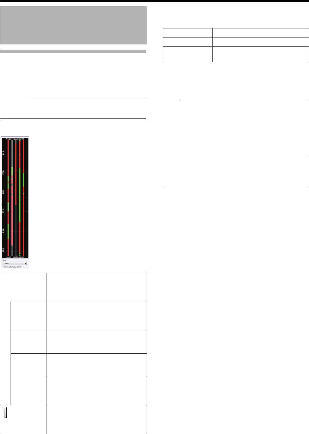
150
<Viewer Part> Basics
Searching for Images by With/
Without Recording
The timeline browser in the right part of the playback screen
enables you to search for images by with/without recording
and/or types.
Caution:
●Timeline is only for reference. It may be misaligned with
the actual time.
䡵Timeline Description
䡵Search by timeline
1 Select a timeline display
2 Drag the timeline upwards or downwards to
search
●Check the time indication pointer when you drag it.
Note:
●Display settings of the timeline browser will not be
retained. Settings will be lost when you restart the Smart
Client.
●With a mouse with a scroll wheel, you can use the wheel
to search through the timeline.
●Double-click any part of the timeline to show images at the
time.
Caution:
●When you drag the timeline upwards or downwards with
your mouse, a part of the timeline may not be updated. In
such a case, exit the Smart Client (APage 134) and then
restart it (APage 133).
Searching for Recorded
Images (continued)
Timeline For indicating recording status. One for
each camera available in the Smart
Client is displayed. The timeline of the
selected camera is highlighted.
Red For indicating recording triggered by
any motion detection or event
occurrence.
(In pink when highlighted)
Green For indicating recording before/after a
motion detection.
(In light green when highlighted)
Black For indicating a period with no
recording.
(In grey when highlighted)
White center
line (time
indication
pointer)
For indicating the time of present
images.
(At the left
hand side of
the timeline/
browser)
For showing or hiding the timeline/
browser.
Item Description
Span For selecting a span to display.
Newest images
at top
Select this check box to reverse the
time flow on the timeline.
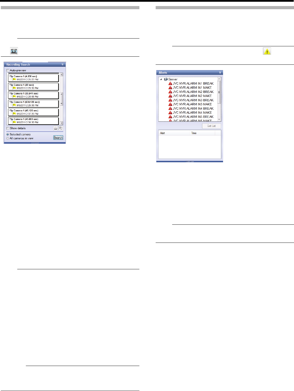
151
Searching for Recorded Images
This section describes procedures to list recorded images by
sequences of images recorded due to any event or motion.
Note:
●If the [Recording Search] section is not displayed, click
[ ] to display it.
1 Select a search target
●When searching for a camera: select a camera to
search in the view, and then select [Selected camera]
in the [Recording Search] section
●When searching for a view: display a view to search,
and then select [All cameras in view] in the [Recording
Search] section.
2 Click [Search]
20 images each for before/after the displayed time are
listed.
●Select the [Auto-preview] check box to view a preview
image when you point the mouse pointer to a
sequence in the list.
3 Click a sequence in the list
All images in the view are displayed according to the date
and time of the selected sequence.
Note:
●When [Auto-preview] is selected, a sequence preview can
be displayed by hovering the cursor over a sequence
name in the list.
●The first image of the selected sequence can be printed
by clicking the print icon in the [Recording Search] section
(APage 156 "Printing a Recorded Image (operation from
surveillance computer)").
●Exporting can be performed by clicking the export icon.
(APage 164 "Saving Images and Audio Sounds on a
USB Flash Memory (Export)")
●The exact date and time of when a detected motion or
event triggered recording to start, and the exact date and
time of the start and finish of a sequence can be displayed
by clicking [Show details].
Caution:
●Multiple sequences in a row may be consolidated as one
sequence depending on settings for recording before/after
any motion/event occurrence (APage 58).
Searching for Recorded Images from
the Alert List
This section describes procedures to list recorded images by
types of trigger (event) of recording.
Note:
●If the [Alerts] section is not displayed, click [ ] to
display it.
1 Select an event from the alert list of the [Alerts]
section
●You can select a preferred event, camera or [Server].
2 Click [Get List]
A list of detected events is displayed.
●You can view recorded images of a selected event by
clicking the event list.
Note:
●Event(s) in the period before and after the time specified
in the [Time Navigation] are obtained in the alert list.
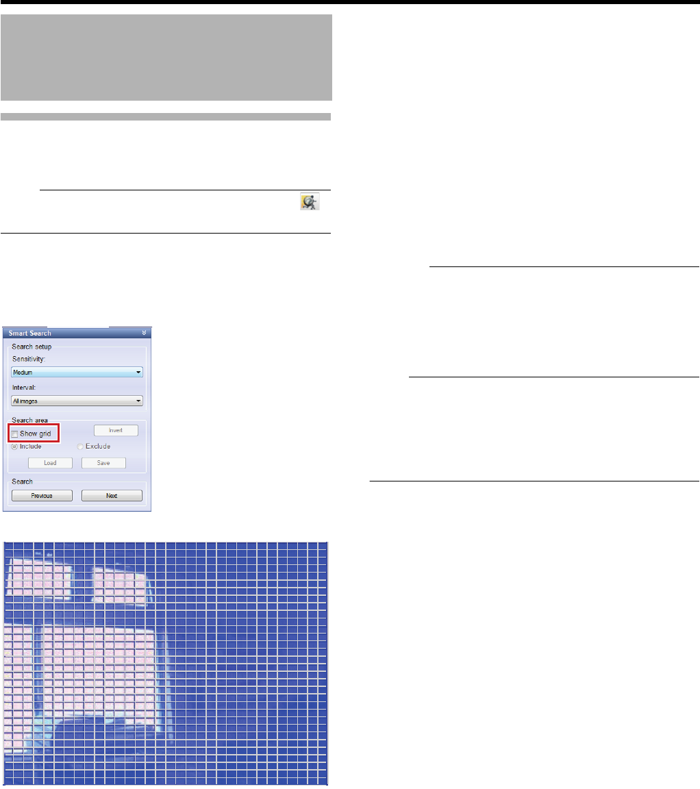
152
<Viewer Part> Basics
Smart Search
You can search for images with any motion by specifying a
search area from recorded images of the selected camera.
Note:
●If the [Smart Search] section is not displayed, click [ ]
to display it.
1 Select a camera for searching by clicking
camera images
2 Select the [Show grid] check box under [Search
area] in the [Smart Search] section
●Blue grids are displayed.
3 Click and drag within the screen to specify an
area to search
The specified area becomes transparent.
●Select the [Include] check box to add the dragged part
to the search area. Select the [Exclude] check box to
delete the dragged part from the search area.
●Select the [Invert] check box to select to include or
exclude the selected area.
4 Select a sensitivity level from the [Sensitivity]
list under [Search setup]
Select from parameters below:
●[Very high]
●[High]
●[Medium]
●[Low]
●[Very low]
5 Specify a time interval in the [Interval] list
6 Search by repeatedly clicking [Next] or
[Previous]
Searching for data where any motion is detected in the
area starts. It will be displayed when any motion is
detected in the area and such motion will be highlighted.
Caution:
●Smart Search searches for data [Forward] or [Backward]
from the present image time.
●When Smart Search is used during recording, the
recording frame rate may decrease. Use the feature to the
extent that the display does not turn red by checking the
CPU meter.
Note:
●You can save the area specified in Step 3 temporarily by
clicking [Save].
You can restore the saved area settings by clicking [Load]
after specifying another area.
●To cancel the area selection, select the [Exclude] check
box and drag the whole area.
Searching for Recorded
Images (continued)
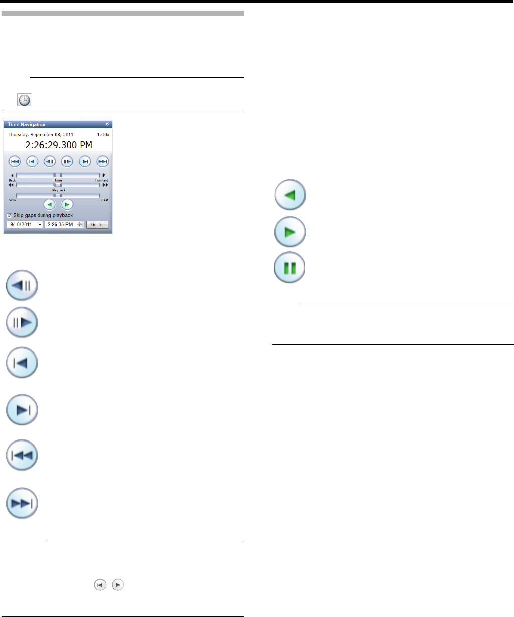
153
Playing back Recorded Images
This section describes procedures to perform playback, stop,
and skip operations in the [Time Navigation] section of the
Smart Client.
Note:
●If the [Time Navigation] section is not displayed, click
[ ] to display it.
Functions of buttons and sliders are as follows.
䢇Browse buttons
Caution:
●The browse buttons are inactive unless a camera is
selected.
●It may take a while to complete movement after you click
the browse buttons . Note that clicking any of the
buttons in a row before completion of the movement will
move the sequence as a whole.
䢇[Time] slider
Drag the slider to the left to show older images and to the
right to show newer images. Use the upper slider for fine
adjustment in a limited time span (0.4 to 240 times), and the
lower slider for rough adjustment in a longer time span (20 to
36,000 times).
䢇[Playback] slider
Playback speed is normal with the slider at the center
position. Drag the slider to the left to decrease the playback
speed and to the right to increase the speed. Drag the slider
to the left end to pause.
The speed during playback is indicated in the upper right in
the master time display part.
䢇[Playback] buttons
Note:
●When the playback slider is at the left end (pause), the
playback buttons are inactive. Set the playback slider to a
preferred speed.
䡵To skip parts with no recording
You can skip parts with no recorded images on the selected
camera during playback by selecting the [Skip gaps during
playback] check box in the [Time Navigation] section.
●When in split screen display, even when there are no
images recorded by the selected camera, if there are
images recorded by another camera this part will not be
skipped. In this case, the image shown last is displayed on
the camera with no recording.
:Move to the previous image of the selected
camera. (Frame rewind)
:Move to the next image of the selected camera.
(Frame advance)
:
Move to the top image of the previous sequence
of the selected camera. (The function may not
work properly depending on the existence or
length of the sequence.)
:
Move to the top image of the next sequence of
the selected camera. (The function may not
work properly depending on the existence or
length of the sequence.)
:
Move to the oldest recorded images of the
selected camera. (The function may not work
properly during playback at 10 or more times
faster than normal)
:
Move to the latest recorded images of the
selected camera. (The function may not work
properly during playback at 10 or more times
faster than normal)
: For reverse playback.
: For normal playback.
: For pausing playback.
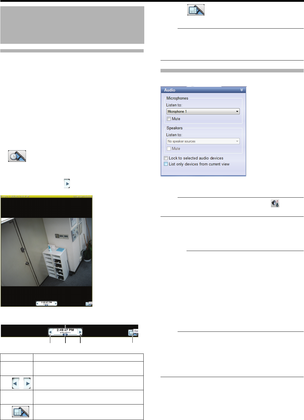
154
<Viewer Part> Basics
Playing Back Recorded Images of
Different Times for Specific
Camera(s) (Independent Playback)
In the playback tab, recorded images of the same time are
played back all together for all cameras.
By using the independent playback function, you can view
images of different recording times for specific camera(s).
●Independent playback function can be used for multiple
cameras.
●Independent playback function can also be performed
from the view in the live tab.
1 Point the cursor to camera images in the view
The independent playback start button appears on the
camera images.
2 Click the independent playback start button
The camera’s title bar turns yellow and playback pauses.
To start playback, click [ ] to the right of the time and
date display.
3 Search for images you want to view
●The controller disappears when the cursor goes
outside of the camera image.
4 Click [ ] to finish independent playback
The color of the title bar returns to normal.
Note:
●If the camera window is displayed small, the slider is not
displayed. In this case, display the slider by maximizing
the Viewer or double-clicking the bar on the upper edge of
the camera window to enlarge it.
Listening to recorded audio sounds
You can listen to audio sounds (recorded sounds) of a
camera with a microphone.
Note:
●If the [Audio] section is not displayed, click [ ] to
display it.
1 Select an audio sound from the [Listen to] list in
[Microphones].
●To mute temporarily, select the [Mute] check box.
Caution:
●Audio sounds may be interrupted when more than one
surveillance computer plays back the sounds.
●When returning to the playback screen from the setting
screen, the microphone selection for the [Audio] section
may return to [None]. Reselect the microphone.
●No audio sound is output during still image display,
searching at other than forward⳯1 speed or frame
advance playback.
●When any playback operation of recorded images is
performed during recording, playback sounds may be
interrupted.
Note:
●If any camera for which the audio sound setting is
specified, the specified audio sound will be output.
●If any camera for which the audio sound setting is not
specified, the last audio sound output will be used
continuously.
●[Speakers] cannot be used on the playback screen.
Searching for Recorded
Images (continued)
Item Description
ATime
and date
For displaying the date and time when the
image was recorded.
B For reverse/normal playback
●
Click once to use them as pause buttons.
CSlider
For changing playback speed during playback.
●Audio sounds will not be played back.
DFor finishing independent playback.
1
32 24

Viewer Part
Applications
This chapter describes procedures to customize views according to specific applications.
Caution:
●If you change settings of Management Application while Smart Client is on, shut down Smart Client, then restart it.
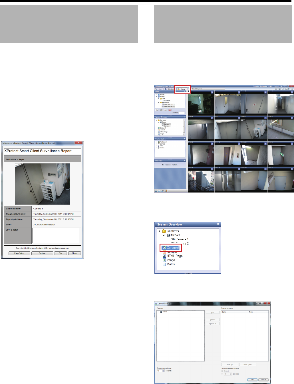
156
<Viewer Part> Applications
You can print a playback image presented on the screen.
Caution:
●You cannot print images from VR-X3200U/VR-X1600U.
This is a function used in [Smart Client] downloaded from
the surveillance computer.
1 Click the [Playback] tab
2 Click [Print...] in the [Print] section
●The [XProtect Smart Client Surveillance Report]
screen appears.
●When any comment is entered in [User's note], it will
also be printed.
3 Click [Page Setup] to configure printer settings
4 Click [Print] to start printing
●When printing is finished, click [Close] to exit the
printing screen.
You can use the carousel function to view images from
multiple cameras in one display position by rotation. You can
also specify the camera switching interval.
1 Click the [Setup] tab
2 Click [Carousel] in the [System Overview]
section and drag to a preferred position in the
view
3 Release the mouse button at a preferred
position
The setting screen appears.
4 Select a camera in the [Cameras] list and click
[Add]
It is added to the [Selected-cameras] list.
Printing a Recorded Image
(operation from surveillance
computer)
Automatically Switching
Images of Multiple
Cameras
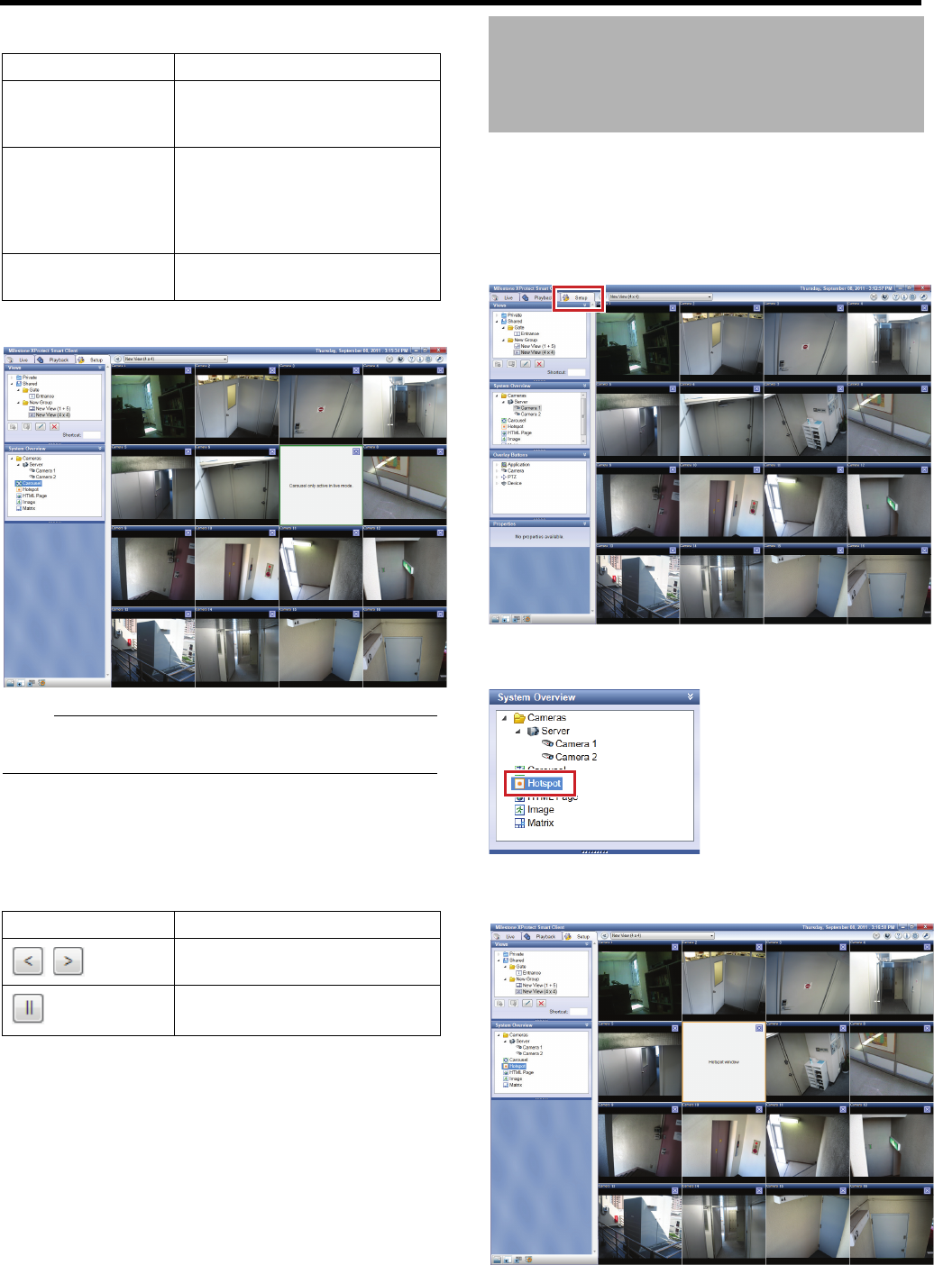
157
5 Specify a display period in seconds
6 Click [OK]
Note:
●The green frame indicates that the area in the frame is set
for the carousel feature.
䡵Changing the Camera While the Carousel
Function is Active
On the live images screen, the following operation icons will
be displayed if you place the cursor in the bar of the camera
window set for the carousel function.
This section describes procedures to display a camera
selected in the view in the hotspot area. You can view an
enlarged view by setting a display area larger than the
others, i.e. [1] in the [1 + 7] layout, as a hotspot.
1 Click the [Setup] tab
2 Click [Hotspot] in the [System Overview] section
and drag to a preferred position in the view
3 Release the mouse button at a preferred
position
Item Description
ADefault carousel
time
For specifying units of seconds
common to multiple cameras, if
applicable.
BTime for
selected camera
For specifying a display period for
cameras selected in the list in
seconds. Select the [Default] check
box to set the units of time set in
[Default carousel time].
CMove Up/
Move Down
For changing the order of the
selected cameras.
Item Description
Change the camera in the order
set for the carousel function.
Pause playback.
Enlarging Images of a
Selected Camera (Hotspot)
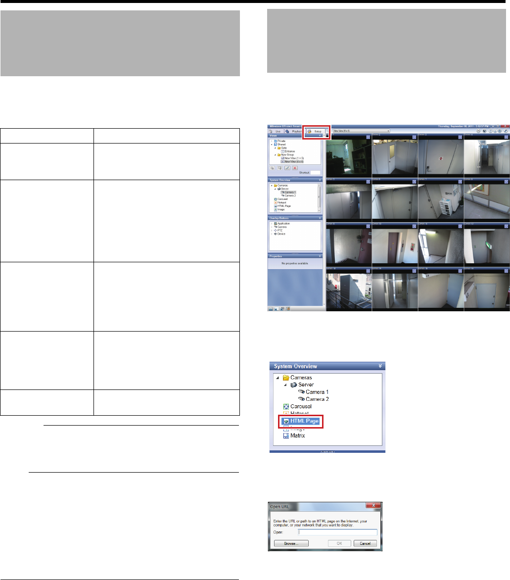
158
<Viewer Part> Applications
4 Select the area you set as [Hotspot] and
configure properties in the [Properties] section
Caution:
●The recording frame rate may decrease when the image
quality is changed. Use the [Full] setting since [Image
quality] settings affect the recording performance.
Note:
●You can use the hotspot feature to use a higher frame rate
for the hotspot and a lower frame rate for the other images
for your convenience.
●The orange frame indicates that the area in the frame is
set as a hotspot.
●When you set multiple views as hotspots and switch
views, the hotspot window you switched to shows camera
images that have been displayed in the view you switched
from.
You can display an HTML page instead of camera images.
1 Click the [Setup] tab
2 Click [HTML Page] in the [System Overview]
section and drag to a preferred position in the
view
3 Release the mouse button at a preferred
position
The [Open URL] window appears.
4 Enter a URL and click [OK]
Enlarging Images of a
Selected Camera (Hotspot)
(continued)
Item Description
Image quality For adjusting resolution and image
quality of images to display. Always
set this to [Full].
Frame rate Frame rate of the display.
Select from [Unlimited] (the same
as default and live settings),
[Medium] (25% frame rate), or
[Low] (5% frame rate) for the frame
rate set on the [Camera Properties]
screen.
Keep when
maximized
Select to preserve the set image
quality when enlarging the display
by double-clicking the camera
window. If not selected, full quality
will always be used when enlarging
the display.
Maintain image
aspect ratio
Select this check box to not
expand/contract images to the
display area size. Images will be
displayed at the original aspect
ratio.
Show For showing/hiding the title bar and
live indicator.
Displaying a Web Page
(HTML Page) in View
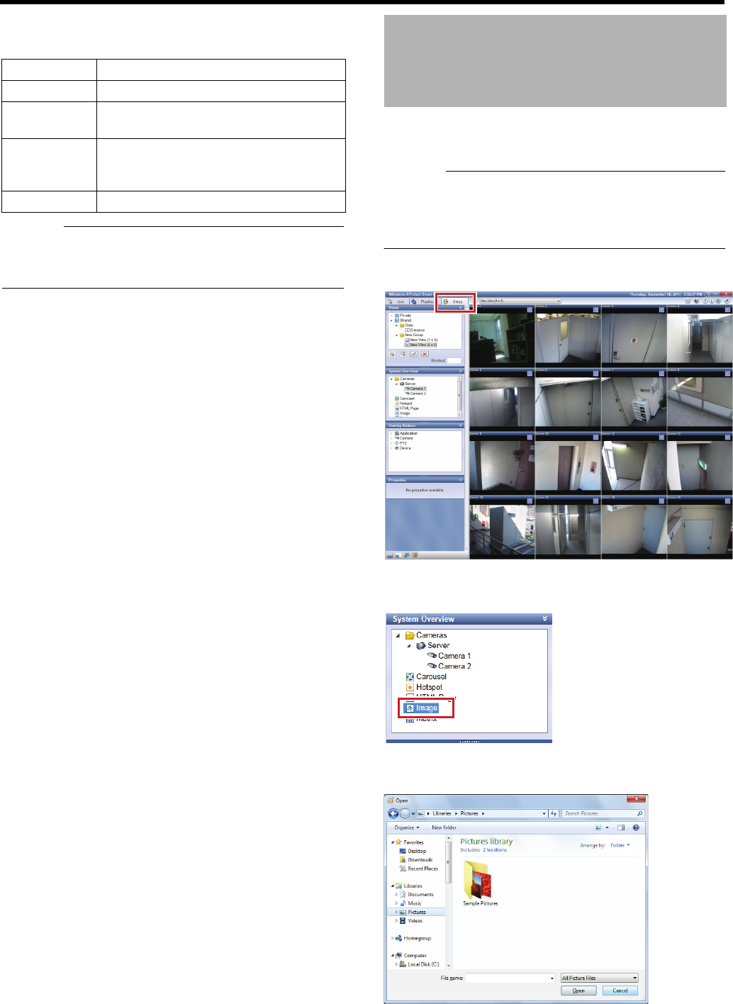
159
5 Select an HTML page in the view and configure
properties in the [Properties] section
Caution:
●This unit does not support ActiveX and Flash, etc.
●Do not install ActiveX.
●Some link destinations may pose security problems.
You can display a still image in the view instead of images
when there is an unused camera.
Caution:
●This setting is for surveillance computers. Do not set still
images on the unit.
●Any still images located on other computers cannot be
used.
1 Click the [Setup] tab
2 Click [Image] in the [System Overview] section
and drag to a preferred position in the view
3
Release the mouse button at a preferred position
The [Open] window appears.
4 Select an image file and click [Open]
Item Description
URL To enter a new URL, click [New…] button.
Scaling For selecting a display size of the HTML
page.
Enable HTML
scripting
Select this check box to specify an HTML
file including navigation and trigger
features.
Hide toolbar Select to hide the toolbar on HTML pages.
Displaying a Still Image
instead of Camera Images
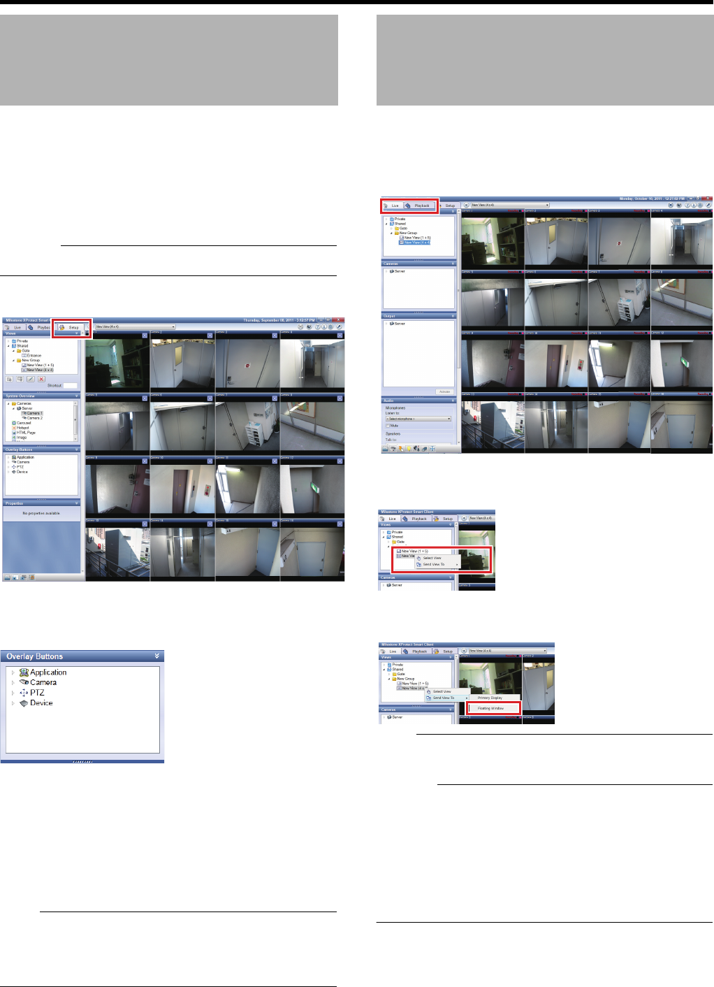
160
<Viewer Part> Applications
You can register frequently-used features as overlay buttons.
●The overlay buttons are displayed when you point the
cursor on camera images and you can click each button to
execute the corresponding feature.
●You can create buttons for each camera image.
●Some features may be unavailable depending on users
due to access limitations of each feature.
Caution:
●Available features vary depending on the camera.
1 Click the [Setup] tab
2 Select a necessary feature in the [Overlay
Buttons] section and drag an overlay button
onto the preferred camera images
3 Release the mouse button
An overlay button for the features is displayed.
4 Resize and/or rename
●Drag a button handle to resize.
●Double-click the button text and edit the button name.
Press the [ENTER] button on the keyboard after
editing.
Note:
●You can also rename the button by right-clicking an
overlay button you want to rename and selecting [Edit].
●To delete an overlay button, right-click the overlay button
you want to delete and select [Delete].
You can display the view as a floating window when, for
example, using multiple monitors.
1 Click the [Live] tab or [Playback] tab
2 In the [Views] section, right-click the view you
would like to display as a floating window
3 Select [Floating Window] from [Send View To] in
the popup menu
Note:
●Display live images in a floating window even when
displaying the [Playback] tab.
Caution:
●If many floating windows are used, the load on the CPU
will be increased.
If the CPU meter is red, reduce the load on the CPU by,
for example, lowering the display or recording frame rate.
●You may not be able to move Smart Client after closing
the floating window. In this case, once maximize Smart
Client, and then restore it to enable you to move Smart
Client.
Creating a Frequently-used
Operation Button
Displaying a Floating
Window
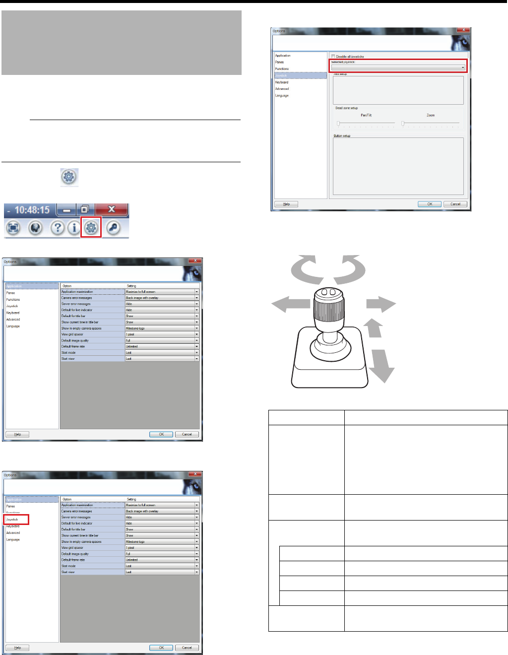
161
You can perform PTZ camera operations by using a joystick
(sold separately).
Note:
●For details of compatible joysticks, consult you nearest
JVC KENWOOD dealer or serve center. You can also
check on our website.
1 Click the [ (Options)] button at the top right
corner of the screen
The [Options] window appears.
2 Select [Joystick]
3 Select a joystick from the [Selected joystick] list
4 Specify the settings for each axis in the [Axis
setup] section
Customizing Joystick
Settings
Item Description
Invert By default, the PTZ camera moves to
the right when you push the joystick to
the right along the X-axis, and moves
up when you pull the joystick towards
you along the Y-axis. The movements
are reversed if you select [Invert].
Absolute The angle of the joystick corresponds
to the direction of the camera.
Action For specifying the action when you
move the joystick.
PTZ Pan Moves the camera horizontally
PTZ Tilt Moves the camera vertically
PTZ Zoom Zooms in or zooms out the camera
No Action No action
Preview Image You can check how each camera
moves on each axis with the joystick.
Joystick
Z axis
X axis
Y axis

162
<Viewer Part> Applications
5 Set the AplayB (dead zone) of the joystick for
pan/tilt and zoom
●As the slider is moved to the right, the dead zone is
expanded and the amount of joystick movement
required for operation of the camera is increased.
6 Assign an action to each joystick button in the
[Button setup] section
●Select the action to assign in the [Action] field.
䡵Disabling Joystick Operation
To disable the joystick operation, select the [Disable all
joysticks] check box.
Customizing Joystick
Settings (continued)

Viewer Part
Reference
This chapter describes operations to make full use of the viewer. Lists of available features in
each screen and settings are also provided.
Caution:
●If you change settings of Management Application while Smart Client is on, shut down Smart Client, then restart it.
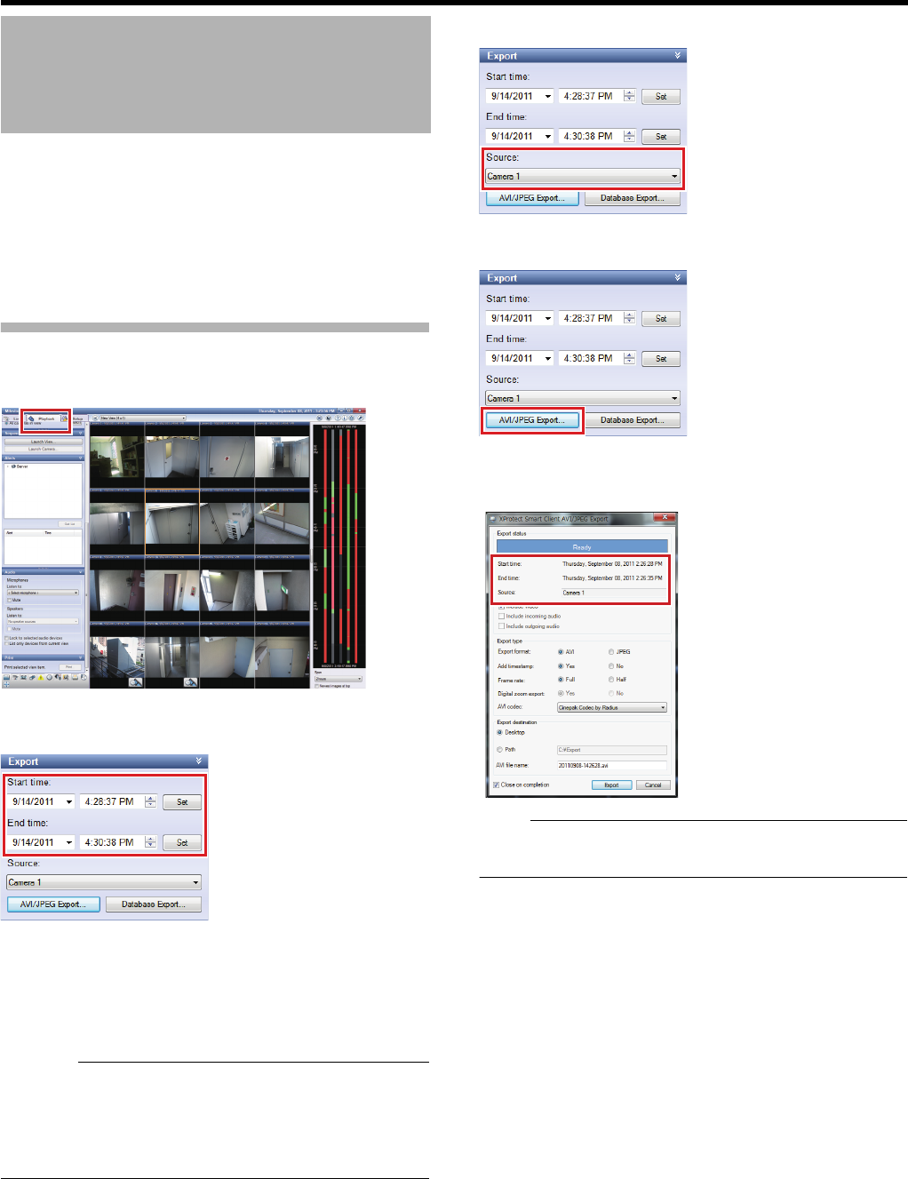
164
<Viewer Part> Reference
Images and audio recorded on this unit can be saved
(exported) as video, still pictures, or in database format, and
be viewed on computers outside the surveillance system.
●A surveillance computer may write recorded images and
audio sounds to a USB flash memory or the desktop.
●When using a USB flash memory, connect the USB flash
memory to the front of this unit beforehand.
Saving as a Video or Still Image
1 Click the [Playback] tab
2 Enter start date/time and stop date/time in the
[Export] section
●When you click [Set] in [Start time], the date/time is
entered in the master time display part in [Time
Navigation].
●When you click [Set] in [End time], the date/time
displayed in the master time display part in [Time
Navigation] plus 1 second is entered.
Caution:
●You may fail to use [Export] if images to export contain
ones with a large time gap by changing the time. In this
case, export images separately, images before changing
the time and ones after changing the time. (Example:
summer time, etc.)
3 Select a camera from the [Source:] list
4 Click [AVI/JPEG Export…]
The export dialog will appear.
●Ensure that the start and end date/time and camera
name you entered are displayed.
Note:
●Preparation for export may take a while depending on
connection status of additional HDD(s).
5 Select the export format
●Select [AVI] (movie clip) or [JPEG] (still image).
●Select whether to display the time in the image to
export.
6 If you have selected [AVI], select a frame rate
●Select either [Full] to transmit all images to an AVI file,
or [Half] to transmit images for each second to
decrease the AVI file size (images are played back in
real time).
7 When AVI format is selected, select the codec
type from the [AVI codec] list
Saving Images and Audio
Sounds on a USB Flash
Memory (Export)
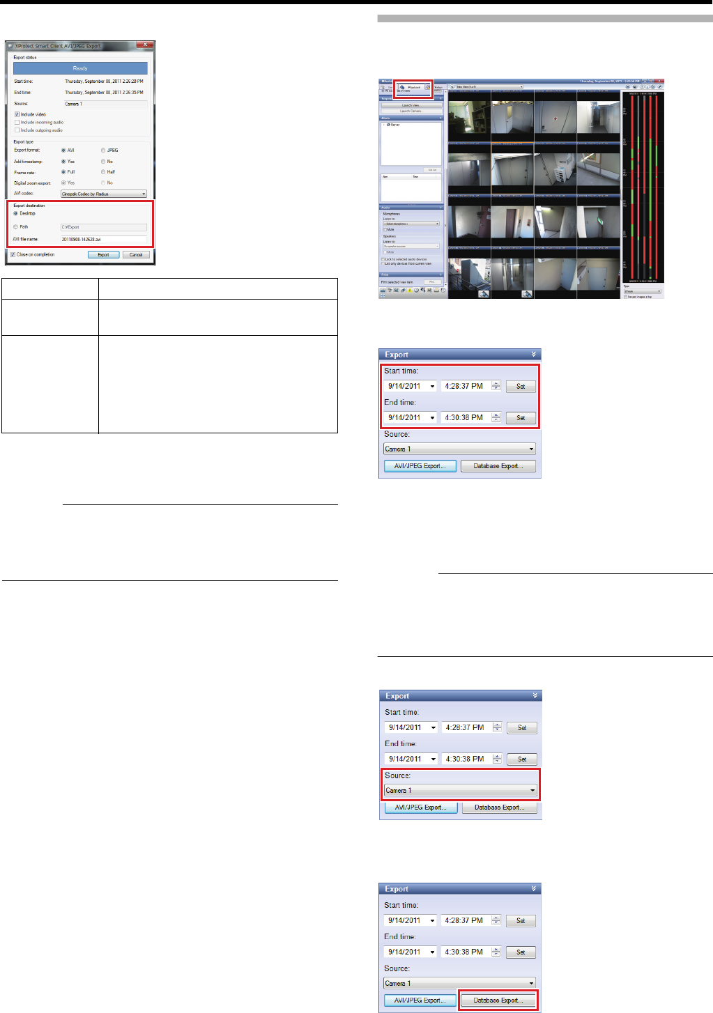
165
8 Specify the export destination
9 Enter a file name (when AVI is selected)
●Unless you specify a name, the file name will be the
export start date/time (Ayyyymmdd-hhmmss.aviB).
Caution:
●If the date/time of data you ran [Export] previously is the
same as Start date/time, AVI file will be overwritten. If you
want to store the previous data, run [Export] only after
changing the path or AVI file name.
10 Click [Export]
An [Exported Images] folder is automatically created in
the specified location and exporting is started.
Saving Images in Database Format
1 Click the [Playback] tab
2 Enter start date/time and stop date/time in the
[Export] section
●When you click [Set] in [Start time], the date/time is
entered in the master time display part in [Time
Navigation].
●When you click [Set] in [End time], the date/time
displayed in the master time display part in [Time
Navigation] plus 1 second is entered.
Caution:
●You may fail to use [Export] if images to export contain
ones with a large time gap by changing the time. In this
case, export images separately, images before changing
the time and ones after changing the time. (Example:
summer time, etc.)
3 Select a camera from the [Source:] list
●When you have selected [- Current view sources -],
images from all cameras in the view will be exported.
4 Click [Database Export…]
Item Description
Desktop Select this radio button to export data to
the desktop.
Path Select this radio button to specify a folder
to which data will be exported and to
enter a path.
●When viewing on another computer,
select [Path] and specify a path from
the USB flash memory.
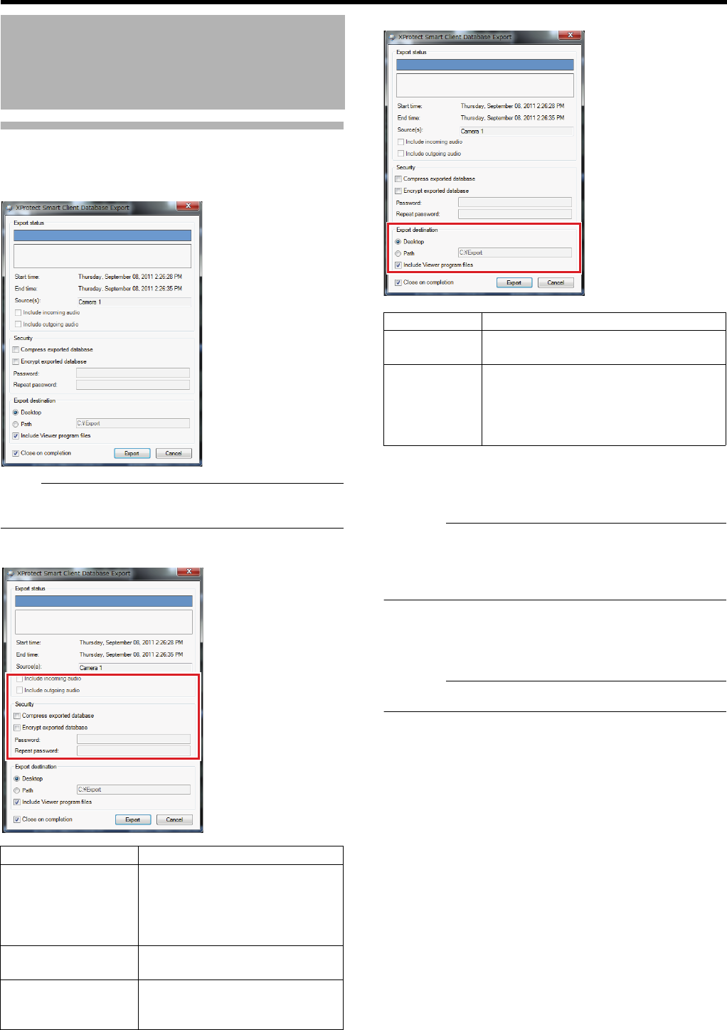
166
<Viewer Part> Reference
Saving Images in Database Format
(continued)
The export dialog will appear.
Note:
●Preparation for export may take a while depending on
connection status of additional HDD(s).
5 Specify contents to save
6 Specify the export destination
●
Select the [Include Viewer program files] check box to
assign a dedicated application to play back recorded
images with data to export. For viewers, refer to
"Viewing Exported Data by Computer" (
A
Page 167).
Caution:
●If the destination of database that you ran [Export]
previously is the same as the current destination, the
database will be overwritten. If you want to store the
previous data, run [Export] only after changing the path.
7 Click [Export]
An [Exported Images] folder is automatically created in
the specified location and exporting is started.
Caution:
●The recording frame rate may decrease during exporting.
Saving Images and Audio
Sounds on a USB Flash
Memory (Export) (continued)
Item Description
Include incoming
audio/Include
outgoing audio
Select these check boxes to
include incoming/outgoing audio
sounds in images to export. (The
check boxes are inactive when
there is no audio source.)
Compress exported
database
Select this check box to compress
data to export.
Encrypt exported
database
Select this check box to encrypt
data to export. Set a password for
decryption.
Item Description
Desktop Select this radio button to export data to
the desktop.
Path Select this radio button to specify a folder
to export data to.
●When viewing on another computer,
select [Path] and specify a path from
the USB flash memory.
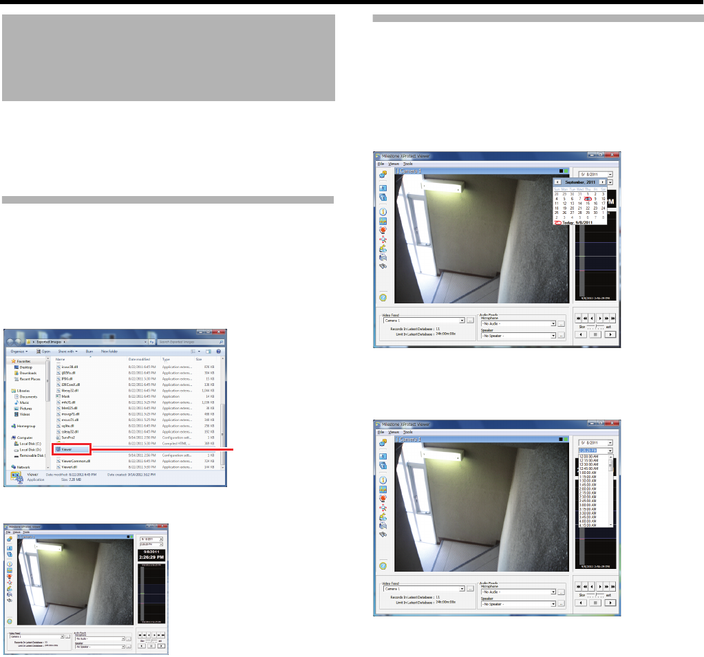
167
To view data exported in the database format by a computer,
use the dedicated viewer (export viewer). The installer of the
dedicated viewer is located in the [Exported Images] folder
created at the time of exporting.
Starting the Export Viewer
1 Copy the exported data ([Exported Images]
folder) onto the computer’s desktop
2 Open the [Exported Images] folder
3 Double-click [Viewer.exe] in the data folder
The viewer is launched.
Viewing Exported Data
䡵Viewing Data on a Specific Date/Time Using
Date/Time Selection
1 Click the [K] button for date selection, and
select the specified date from the calendar
Images of the selected date appear.
2 Click the [K] button for time selection, and
select a specific time
Images of the selected time appear.
Viewing Exported Data by
Computer
Double-
click
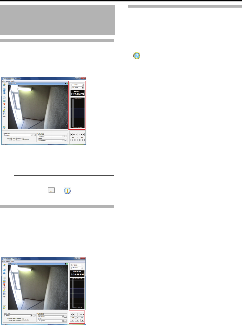
168
<Viewer Part> Reference
Viewing Exported Data (continued)
䡵Viewing Data on a Specific Date/Time Using
Timeline
The vertical timeline indicates the progress status of a
recording operation.
1 Drag the mouse pointer upwards or downwards
on the Timeline
●You can view data at the specified date/time while
checking the images.
Note:
●You can also use the Smart Search function. If the start
time and end time cannot be set when using the Smart
Search function, click [ ] of [ ] > [Image Feed] and
select each file to play back (extension ".pqz") one by one.
Data Playback/Stopping Data
Playback
䡵Playback
1 Set the playback speed using the speed control
2 Click the Play button
●The database is played back at the specified speed.
䡵Stopping Playback
1 Click the Stop button
●Data playback stops.
Exiting the Export Viewer
1 Select [File] > [Exit] from the menu
●The Export Viewer is closed.
Note:
●You can also click [×] on the top right of the screen to exit
the viewer.
●For details of the viewer, refer to the "Help" (by clicking
) or Milestone XProtect Smart Client User’s Manual
available on the website of Milestone Systems (http://
www.milestonesys.com).
●The URL address may be subject to change.
Viewing Exported Data by
Computer (continued)
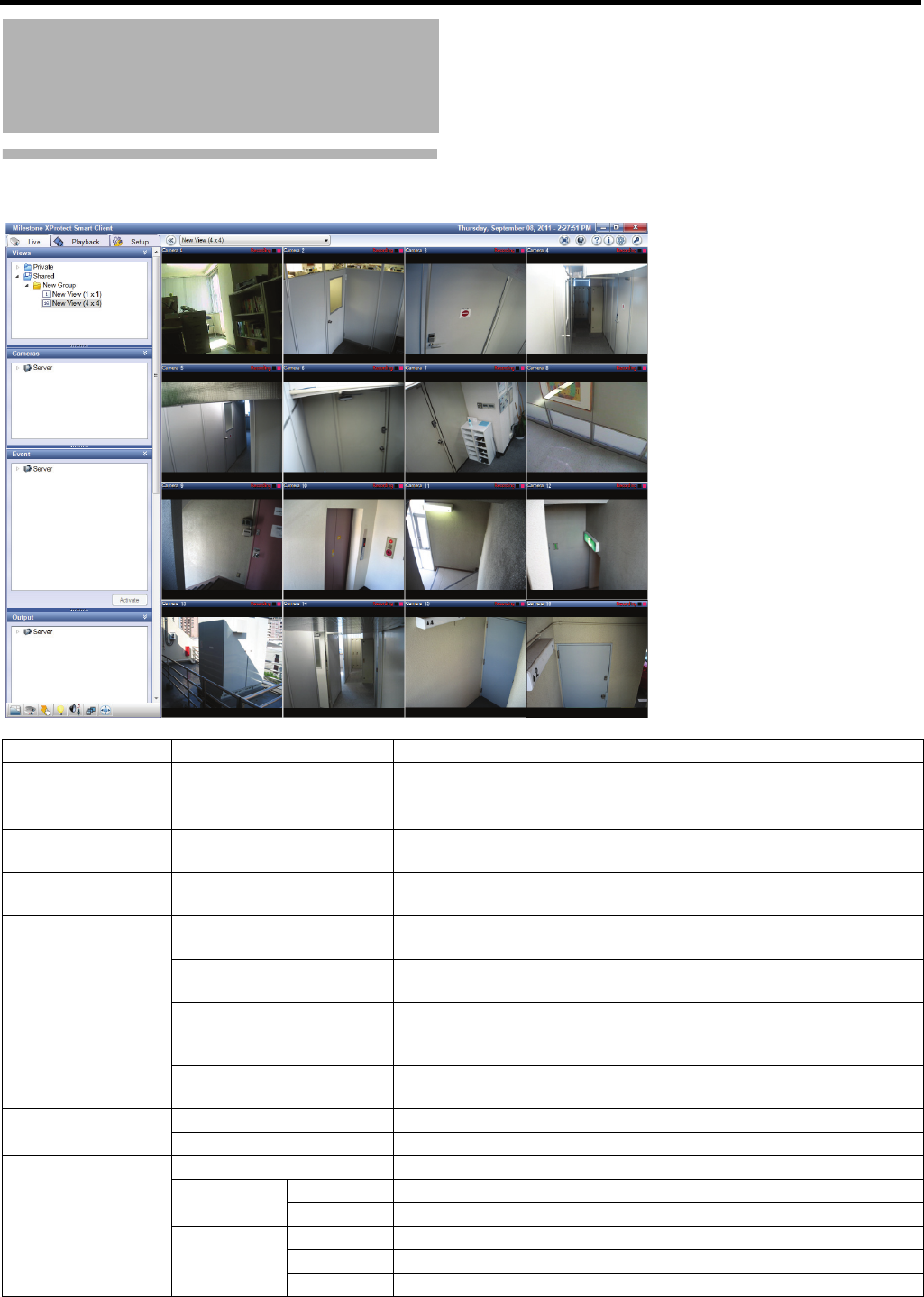
169
Live Screen
Operations and Settings
Available on Each Screen
Section Item Description
Views ^For hierarchical display of the registered views.
Cameras ^For displaying a camera list. By selecting a camera not listed in the view
and dragging it into the view, you can view images from the camera.
Event ^For starting a manual event. Select an event to start from the list and
click [Activate].
Output ^For activating an output. Select an output to activate from the list and
click [Activate].
Audio Microphones For selecting a source (camera) you want to listen to audio sounds from.
●Select the [Mute] check box to mute the microphone.
Speakers For selecting a speaker to use.
●During talking, keep [Talk] clicked.
Lock to selected audio
devices
Check the check box to keep using the selected microphone and/or
speaker when you select another camera with a microphone and/or
speaker.
List only devices from
current view
Check the check box to list the audio devices in the view only.
Sequence Explorer Launch View... For displaying a list of sequence images of all cameras in the view.
Launch Camera... For displaying a list of sequence images of the selected camera.
PTZ Control Presets For selecting a preset position.
Fisheye PTZ
positions
Load For moving to a location where the fisheye lens camera is saved.
Save For saving a specific location of the fisheye lens camera.
Navigation
buttons
Arrows For directing the PTZ camera in the direction of each arrow.
+/- For zooming in/out.
Digital zoom Select this check box to use the digital zoom feature.
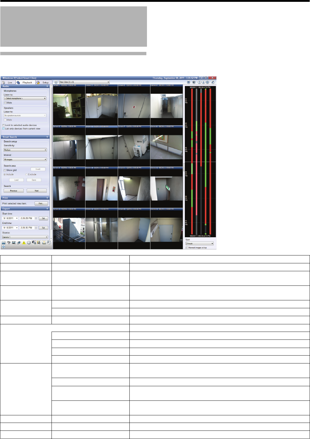
170
<Viewer Part> Reference
Playback Screen
Operations and Settings
Available on Each Screen
(continued)
Section Item Description
Views ^For hierarchical display of the registered views.
Cameras ^For displaying a camera list. By selecting a camera not listed in the view
and dragging it into the view, you can view images from the camera.
Recording Search ^For searching for sequences of recorded images by recorded date and
time.
Sequence Explorer Launch View... For displaying a list of sequence images of all cameras in the view.
Launch Camera... For displaying a list of sequence images of the selected camera.
Alerts ^For displaying a list of images triggered by alerts.
Time Navigation For date/time search and playback operations for recorded images.
(Date/time) Date/time of recorded images presented in the view (master time).
Playback navigation button For performing playback and frame advance.
Skip gaps during playback Select this check box to skip the specified period.
(Date) (Time) [Go To] For specifying search date/time and displaying in [Go To].
Audio Microphones For selecting a source (camera) you want to listen to audio sounds from.
●Select the [Mute] check box to mute the microphone.
Speakers ●Disabled in the playback screen.
Lock to selected audio
devices
Check the check box to keep using the selected microphone when you
select another camera with a microphone.
List only devices from current
view
Check the check box to list the audio devices in the view only.
Smart Search ^For performing Smart Search.
Print ^For printing recorded images.
Export ^For saving recorded images on the desktop, etc.
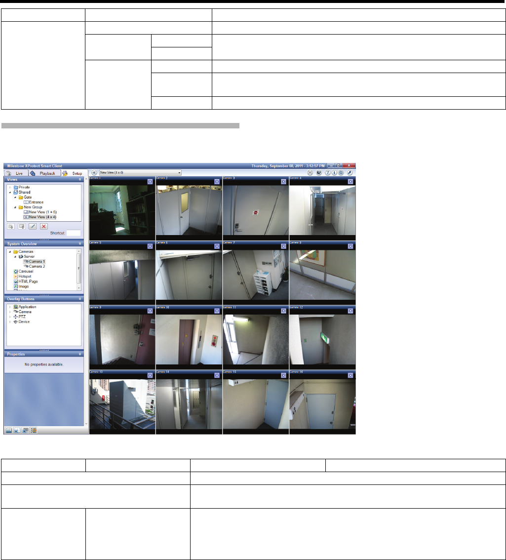
171
Setting Screen
䢇: Initial value
PTZ Control Presets ●Disabled in the playback screen.
Fisheye PTZ
positions
Load ●Disabled in the playback screen.
Save
Navigation
buttons
Arrows Move the zoomed position during digital zoom.
+/- For zooming in/out. (Disabled unless the [Digital zoom] check box is
selected.)
Digital zoom Select this check box to use the digital zoom feature.
Section Item Description
Section Item Preset Values Description
Views For creating and editing a view.
System Overview For adding cameras and setting features such as HTML pages and hotspots
for the view.
Overlay Buttons Application
Camera
PTZ
Device
For creating an overlay button.

172
<Viewer Part> Reference
Properties
When the camera window is selected
Camera name ^Display the name of the selected camera.
Image quality 䢇Full
Super high (for megapixel)
High
Medium
Low
Set the display image quality.
Keep when maximized Select check box
䢇Do not select check box
Select to preserve the set image quality
when enlarging the display by double-
clicking the camera window. If not selected,
full quality will always be used when
enlarging the display.
Frame rate 䢇Unlimited
Medium
Low
Set the display frame rate.
Fisheye split mode 䢇No split
2 at a time
Select whether to use split mode when a
fisheye camera is selected.
Maintain image aspect
ratio
䢇Select check box
Do not select check box
Select to preserve the aspect ratio of the
camera image.
Update on motion Select check box
䢇Do not select check box
If selected, the live image screen will be
updated only when motion is detected.
Sound on motion
detection
䢇Always off
Always on
Select whether sound is emitted to notify of
motion detection on the live image screen.
Sound on event 䢇Always off
Always on
Select whether sound is emitted to notify of
an event occurring on the live image screen.
In order to use this function, it is necessary
to set the event notification.
Display settings
Use default
display
settings
䢇Select check box
Do not select check box
If selected, the showing/hiding of the title
bar and live indicator is determined by the
settings of [Application] in the [Options]
settings (APage 176).
Show title bar 䢇Select check box
Do not select check box
If selected, the showing/hiding of the title
bar is set separately to the settings of
[Application] in the [Options] settings
(APage 176).
Show live
indicator
䢇Select check box
Do not select check box
If selected, the showing/hiding of the live
indicator is set separately to the settings of
[Application] in the [Options] settings
(APage 176).
Apply to all ^Apply all of the above settings to every
camera.
When the HTML window is selected
URL ^Display the URL. To enter a new URL, click
[New...].
Scaling 䢇No scaling
1280 x 1024
1024 x 768
860 x 600
640 x 480
320 x 200
Select the display size for HTML pages.
Enable HTML scripting 䢇Select check box
Do not select check box
Select when specifying HTML files which
contain navigation or trigger functions.
Hide toolbar 䢇Select check box
Do not select check box
Select to hide the toolbar on HTML pages.
Section Item Preset Values Description

173
Properties (continued)
When the Matrix window is selected
Image quality 䢇Full
Super high (for megapixel)
High
Medium
Low
Set the image quality of the distributed
image.
Keep when maximized Select check box
䢇Do not select check box
Select to preserve the set image quality
when enlarging the display by double-
clicking the camera window. If not selected,
full quality will always be used when
enlarging the display.
Frame rate 䢇Unlimited
Medium
Low
Set the frame rate of the distributed image.
Maintain image aspect
ratio
䢇Select check box
Do not select check box
Select to preserve the aspect ratio of the
camera image.
Window index 1 to 30 Set the window ranking order for when
multiple Matrix windows are set within the
view. Starting from A1,B newly distributed
live images from cameras are displayed in
order.
Show
Use default
display
settings
䢇Select check box
Do not select check box
If selected, the showing/hiding of the title
bar and live indicator is determined by the
settings of [Application] in the [Options]
settings (APage 176).
Title bar 䢇Select check box
Do not select check box
If selected, the showing/hiding of the title
bar is set separately to the settings of
[Application] in the [Options] settings
(APage 176).
Live indicator 䢇Select check box
Do not select check box
If selected, the showing/hiding of the live
indicator is set separately to the settings of
[Application] in the [Options] settings
(APage 176).
Connection Settings... ^Set the TCP port and password for
distributed image signals.
Section Item Preset Values Description

174
<Viewer Part> Reference
Properties (continued)
When a hot spot is selected
Image quality 䢇Full
Super high (for megapixel)
High
Medium
Low
Set the display image quality.
Keep when maximized Select check box
䢇Do not select check box
Select to preserve the set image quality
when enlarging the display by double-
clicking the camera window. If not selected,
full quality will always be used when
enlarging the display.
Frame rate 䢇Unlimited
Medium
Low
Set the display frame rate.
Maintain image aspect
ratio
䢇Select check box
Do not select check box
Select to preserve the aspect ratio of the
camera image.
Show
Use default
display
settings
䢇Select check box
Do not select check box
If selected, the showing/hiding of the title
bar and live indicator is determined by the
settings of [Application] in the [Options]
settings (APage 176).
Title bar 䢇Select check box
Do not select check box
If selected, the showing/hiding of the title
bar is set separately to the settings of
[Application] in the [Options] settings
(APage 176).
Live indicator 䢇Select check box
Do not select check box
If selected, the showing/hiding of the live
indicator is set separately to the settings of
[Application] in the [Options] settings
(APage 176).
When an image is selected
Image location ^Display the storage location of the image
file. To select a new image, click [...].
Section Item Preset Values Description

175
Properties (continued)
When automatic screen conversion is selected
Image quality 䢇Full
Super high (for megapixel)
High
Medium
Low
Set the display image quality.
Keep when maximized Select check box
䢇Do not select check box
Select to preserve the set image quality
when enlarging the display by double-
clicking the camera window. If not selected,
full quality will always be used when
enlarging the display.
Frame rate 䢇Unlimited
Medium
Low
Set the display frame rate.
Maintain image aspect
ratio
䢇Select check box
Do not select check box
Select to preserve the aspect ratio of the
camera image.
Show
Use default
display
settings
䢇Select check box
Do not select check box
If selected, the showing/hiding of the title
bar and live indicator is determined by the
settings of [Application] in the [Options]
settings (APage 176).
Title bar 䢇Select check box
Do not select check box
If selected, the showing/hiding of the title
bar is set separately to the settings of
[Application] in the [Options] settings
(APage 176).
Live indicator 䢇Select check box
Do not select check box
If selected, the showing/hiding of the live
indicator is set separately to the settings of
[Application] in the [Options] settings
(APage 176).
Carousel Setup ^Set the camera to display and the order.
Section Item Preset Values Description
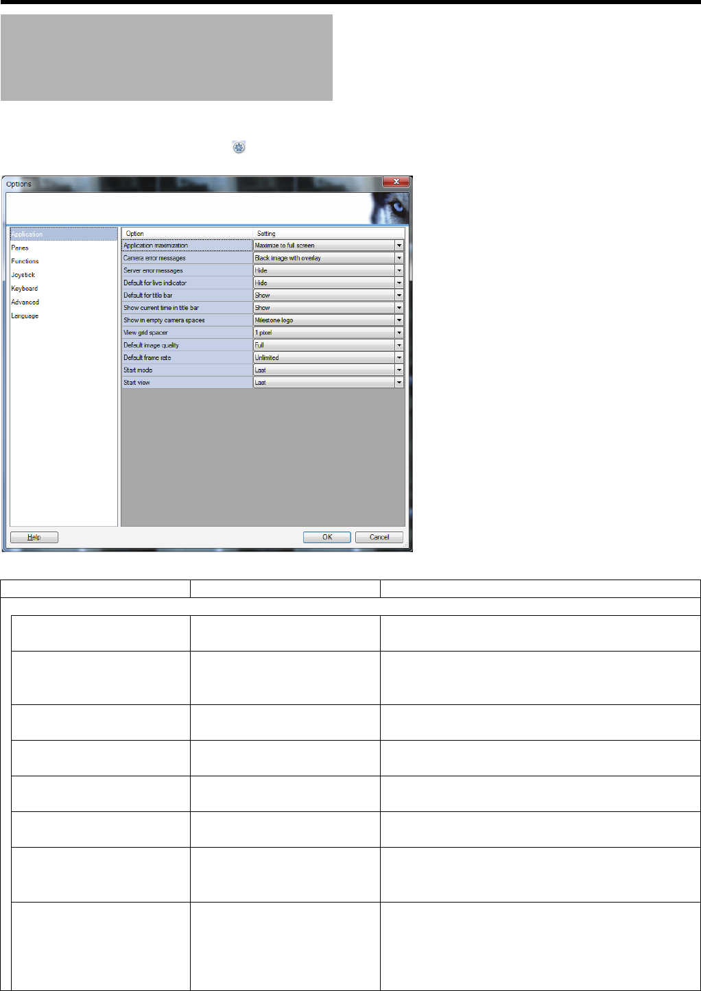
176
<Viewer Part> Reference
You can configure advanced settings of the viewer in the option setting screen.
To display the option setting screen, click “ ” shown at the upper right of the screen.
䢇: Initial value
Option Setting
Item Preset Values Description
Application
Application maximization 䢇Maximize to full screen
Maximize as normal window
Select a display type when maximizing the Smart Client
screen.
Camera error messages Show as overlay
䢇Black image with overlay
Hide
For selecting the camera error message display method.
Server error messages Show as overlay
䢇Hide
For selecting whether to show or hide messages from
the server.
Default for live indicator Show
䢇Hide
For selecting whether to show or hide the live indicator.
Default for title bar 䢇Show
Hide
Set whether to display the title bar.
Show current time in title bar 䢇Show
Hide
Set whether to display the current time on the title bar.
Show in empty camera spaces 䢇Milestone logo
Nothing
Black image
For selecting contents to show in a space where no
camera is assigned in the view.
View grid spacer Hide
䢇1 pixel
2 pixels
3 pixels
4 pixels
For specifying the grid interval.

177
Application (continued)
Default image quality 䢇Full
Super high
High
Medium
Low
For specifying the default image quality of the Smart
Client.
Default frame rate 䢇Unlimited
Medium
Low
For specifying the default frame rate of the Smart Client.
Start mode Full screen
Maximized
Window
䢇Last
For specifying the default screen size of the Smart Client.
Start view 䢇Last
None
Ask
For specifying whether to start the view at the startup of
the Smart Client.
Panel
Mode 䢇Available
Unavailable
For selecting a section used in each of live, playback and
setting screens.
Function
Setting
Functions
Live/Camera playback 䢇Available
Unavailable
For selecting whether to enable functions of each of live,
playback and setting screens (modes).
Live/Overlay buttons 䢇Available
Unavailable
Playback/Independent
playback
䢇Available
Unavailable
Setup/Edit overlay buttons 䢇Available
Unavailable
Setup/Edit video buffering Available
䢇Unavailable
Joystick ^For allocating the PTZ features to a joystick.
Disable all joysticks Select check box
䢇Do not select check box
Select this check box to disable joysticks.
Selected joystick ^For selecting a joystick to configure settings for.
Axis setup For setting available axis.
Invert display By default, the PTZ camera moves to the right when you
push the joystick to the right along the X-axis, and moves
up when you pull the joystick towards you along the Y-
axis. The movements are reversed if you select [Invert].
Absolute value The angle of the joystick corresponds to the direction of
the camera.
Action For specifying the action when you move the joystick.
Preview Image For checking settings by preview display.
Dead zone
setup
Pan/Tilt Set the dead zone of the joystick. As the [pan/tilt]/[zoom]
slider is moved to the right, the dead zone is expanded
and the amount of joystick movement required for
operation of the camera is increased.
Zoom
Button setup ^Select actions in the [Action] field and assign an action to
each button on the joystick.
Item Preset Values Description

178
<Viewer Part> Reference
Keyboard For allocating a shortcut key combining with keys such as Ctrl or Alt and other key(s) to a
certain operation.
Press shortcut key ^Press a combination of shortcut keys you want to
register.
Use new shortcut in 䢇Global
Live mode
Playback mode
Setup mode
For specifying in which screen of the Smart Client the
shortcut key to register will be used.
Categories/Commands PTZ
Application
Events All
Camera
Keyboard
Detached windows
Views
Views All
Time Navigation
For selecting a category of a command to allocate and
then selecting the command from the command list of
the category.
Assigned keys ^A list of assigned combinations of shortcut keys is
displayed.
Delete ^For deleting a shortcut selected in [Assigned keys].
Advanced Maximum
decoding
threads
Auto
䢇Normal
1 to 8
Set the number of threads used when decoding a video
stream. The performance on the live/playback screen will
be increased for multicore computers. Select the optimal
setting according to the number of computers and
cameras used, and the frame rate setting.
Caution:
●This setting cannot be adjusted for each individual
screen or camera.
Deinterlacing 䢇No filter
Vertical stretch top field
Vertical stretch bottom field
Content adaptive
When the camera image is interlaced, specify the
deinterlacing method. If the camera image is not
interlaced, this setting will have no effect on image
quality or performance.
Caution:
●When the camera image is interlaced, the recording
frame rate may decrease.
Language 䢇English (United States) For selecting the language used in the Smart Client.
To apply settings, restart the Smart Client.
Item Preset Values Description
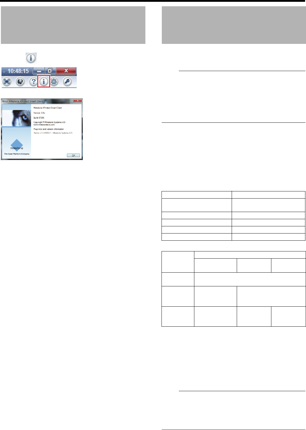
179
1 Click [ (About)]
The version information is displayed.
2 Click [OK] to close the window
Set the display position, image quality, etc. of the distributed
live video using the Matrix function.
Note:
●Matrix is a function to distribute images from the recorder
to display them on the viewer (Smart Client) installed on
any computer on the network. Settings for Matrix are
mainly made on the recorder. When an event occurs or
motion is detected, or important live images are to be
shared with another user, etc., live images are
automatically displayed on the specified computer.
1 Click the [Setup] tab
2 Drag [Matrix] in the [System Overview] section
into the view
3
Release the mouse button at a preferred position
A thin blue frame is displayed.
4
Make the image settings in the [Properties] section
●Image quality
●Frame rate
●
Maintain image aspect ratio: Select this check box to
maintain camera image aspect ratio. Deselect this check
box to reduce images according to the Matrix position.
5 Click [Connection Settings...] and set a TCP port
and a password
●
Enter the TCP port and password set in Matrix of
Management Application. (
A
Page 53 "Action Setup—
Distributing Camera Images (Matrix)")
Note:
●Multiple Matrix positions can be set in the view. In such a
case, set the window ranking order in [Window index] in
the [Properties] section. The most recently distributed
camera image will always be displayed in the Matrix 1
position.
Checking Version
Information
Setting the Matrix Display
Area
Item Description
Full The same image quality as
the original images (default)
Super high (for megapixel)
640 pixels (VGA)
High 320 pixels (QVGA)
Medium 200 pixels
Low 160 pixels
Item Frame rate by formats
JPEG MPEG
(I frame)
MPEG
(P frame)
Unlimited
(default)
For transmitting all frames.
Medium For transmitting
1 frame for every
4 frames.
For transmitting all frames.
Low For transmitting
1 frame for every
20 frames.
For
transmitting
all frames.
No
transmission.

Others
This section contains reference information such as the recording performance, summary of
initial values, and specifications of this unit. You may also want to refer to this chapter when any
trouble occurs.

181
Others
●Refer to the relevant instruction manuals of network cameras used.
R : Compatible
^:Not compatible
Note:
●When VN-V685U and VN-V686BU Series are registered to NVR, do not enable the audio device although it is displayed. If it is
enabled, camera images may not be displayed correctly.
●When VN-X35U is used, make sure that the firmware version of VN-X35U is V2.00 or a newer version.
●When sending out audio data to VN-V26U, make sure that the firmware version of VN-V26U is 1.01 or a newer version.
Compatible Network
Cameras
Functions JPEG MPEG4 H.264 Mega Pixel PTZ Microphone Speaker
Network camera
JVC
VN-V25U RR
^^^^^
VN-V26U RR
^^^ RR
VN-V685U RR
^^ R^^
VN-V686U RR
^^ R^^
VN-V686BU RR
^^ R^^
VN-V686WPBU RR
^^ R^^
VN-V225U/VPU RR
^^^ RR
VN-X235U/VPU RR
^RRRR
VN-C20U R^^^^^^
VN-C655U R^^^ R^^
VN-C625U R^^^ R^^
VN-E4U/E R^^^ RRR
VN-C215U R^^^^^^
VN-X35U RR
^RRRR
AXIS
M1054 R^RRRRR
M1114 R^RRRRR
M 3014
R^RRR
^^
P 1346 R^RRRRR
182
Others
The actual recording time varies according to the camera settings, input image content, and condition of the HDD.
Use the tables below as a guide to the recording time.
Caution:
●Recording time may be reduced by about 10% depending
on HDD status and images.
●Recording time may be reduced due to secular variation
of HDD.
Recording Time Schedule
䢇JPEG VGA 32KB Recording (Unit: Hour)
Frame rate per channel, per second [ips] 30 15 10 5 3 1 0.5 0.2
Recording
channel
Video 16 ch ^(*) 31 47 93 156 467 933 2333
Video 16 ch + Audio 2 ch ^(*) 31 47 93 156 452 878 2018
Video 32 ch ^^^47 78 233 467 1166
Video 32 ch + Audio 2 ch ^^^47 77 230 452 1082
䢇H.264 Recording (Unit: Hour)
Bit rate per channel, per second [bps] 3.6M 2M 1.8M 1M 660K 330K 128K 64K
Typical example of the bitrate above Full HD
30ips
720P
30ips
Full HD
15ips
720P
15ips
VGA
30ips
VGA
15ips
VGA
1ips
VGA
(Low
quality)
1ips
Recording
channel
Video 16 ch (*) 32 58 65 117 181 362 933 1866
Video 16 ch + Audio 2 ch (*) 32 58 65 116 179 353 878 1659
Video 32 ch ^^(*) 32 58 90 181 467 933
Video 32 ch + Audio 2 ch ^^(*) 32 58 90 179 452 878
(*) Available only when RAID10 is built.
24-168 169-720 721-
1day to 1
week
1 week to 1
month
Over 1
months

183
Settings of This Unit
Default Value List
䡵StartUp auto-display setting
Smart Client [Do not select check box]
CPU Meter [Select check box]
HDD Meter [Do not select check box]
Hardware error notification setting
Notify by dialog [Select check box]
Notify by mail [Select check box]
䡵NAS Setting
User name [None]
Password [None]
䡵IP Lease Setting
IP Lease feature [Enable IP Lease]
Lease period [Unlimited]
Parameters
Head IP address [192.168.0.100]
Number [20 Units]
Subnet mask [255.255.255.0]
Gateway [192.168.0.254]
Primary DNS [192.168.0.253]
Secondary DNS [192.168.0.252]
Domain name [None]
䡵SNMP Setting
Enable SNMP [Do not select check box]
Enable TRAP [Do not select check box]
SNMP Manager IP address ^ (IP address)
Community name ^ (1 to 32 characters. Alphanumeric
characters only.)
Monitoring interval CPU Load [10 sec]
D drive writing rate [60 sec]
Smart Client [10 sec]
Camera status [60 sec]

184
Others
Settings of This Unit (Network
Settings)
䡵Mail Setting
Mail to [None]
Server name [None]
SMTP Port [25]
POP Port [110]
User ID [None]
Password [None]
Mail Authentication [None]
Mail from [None]
䡵International Setting
Select language [English]
䡵JVC Log Setting
LOG storage period [Days] [10]
Automatically delete old log file in case of storage space shortage. [Select check box]
䡵HDD meter setting
Update interval [10 seconds]
Transparency [0%]
Select drives to monitor [Do not select check box]
䡵LAN1
Network adapter interface name Intel(R) 82578DM Gigabit Network
Connection
Obtain an IP address automatically [Do not select check box]
IP address [192.168.0.253]
Subnet Mask [255.255.255.0]
Default Gateway [None]
Preferred DNS Server [None]
Alternate DNS Server [None]
Host Name [JVCNVR]
DNS Domain Name [None]
䡵LAN2
Network adapter interface name Realtek RTL8168D/8111D Family PCI-E
Gigabit Ethernet NIC (NDIS 6.20)
Obtain an IP address automatically [Do not select check box]
IP address [192.168.1.253]
Subnet Mask [255.255.255.0]
Default Gateway [192.168.1.254]
Preferred DNS Server [None]
Alternate DNS Server [None]
Host Name [JVCNVR]
DNS Domain Name [None]

185
Management Application (Advanced
Configuration)
䡵Hardware Devices
Item Initial value
Hardware Devices (Hardware Device Properties)
Name and Video
Channels
Hardware name and video
channels
Hardware name
Enable (Depending on cameras)
Network, Device
Type and License
Network Address [None]
HTTP port [80]
Use default HTTP port [Select check box]
FTP port [21]
Use default FTP port [Select check box]
User name [None]
Password [None]
Device type Hardware type [None]
Serial number (MAC address) [None]
Device license key (DLK) [None]
PTZ Device The connected camera features pan, tilt, and zoom
functions.
[Do not select check box]
COM1 PTZ type/COM2 PTZ type [None]
Type [Fixed]
Port [None]
Port address [0]
Fisheye Fisheye Enable fisheye [Do not select check box]
Fisheye license key [None]
Camera (Camera Properties)
Camera
Properties
General camera settings Enabled (Depending on cameras)
Camera name [None]
Camera shortcut number [None]
Frame rate Frame rate selection
(MJPEG)
Regular frame rate:
Live frame rate
[20 Second]
Regular frame rate:
Recording frame rate
[10.00 Second]
Enable speedup [Do not select check box]
Speedup frame rate:
Live frame rate
[20 Second]
Speedup frame rate:
Recording frame rate
[10.00 Second]
On motion [Do not select check box]
On Event [Do not select check box]
Start event [None]
Stop event

186
Others
Camera (Camera Properties) (continued)
Video Video Properties
Note:
●The displayed items and initial
settings differ depending on the
camera. For details, see the
instruction manual of the camera.
Audio Audio selection Default microphone [None]
Default speaker [None]
Recording
Properties
Recording Recording settings (Depending on cameras)
Built-in motion detection [Do not select check box]
Event [Do not select check box]
Start event [None]
Stop event
Enable pre-recording [Do not select check box]
second(s) [None]
Enable post-recording [Do not select check box]
second(s) [None]
Recording and
Archiving Paths
Recording settings Recording path D:\MediaDatabase
Archiving path [Using Dynamic Path]
Retention time [7 Day(s)]
Database repair action [Repair, scan, delete if fails]
General archiving settings for all cameras
Configure Dynamic
Paths...
Enable dynamic path selection
for archives
[Select check box]
Use [Select check box]
Drive [None]
Path [None]
Drive Size [None]
Free Space [None]
New UNC path [None]
Item Initial value

187
䡵Cameras and Storage Information
Camera (Camera Properties) (continued)
Event Notification Event Notification Available events [None]
Selected events [None]
Configure events [None]
Output Output activation Available output [None]
On manual activation [None]
On motion detected [None]
Motion Detection
and Excluded
Regions
Motion detection Sensitivity [40]
Motion [640]
Motion detection interval [240 milliseconds]
Exclude regions Enable [Do not select check box]
Show Grid [Do not select check box]
PTZ Preset
Positions
PTZ preset positions PTZ Type [None]
PTZ Patrolling Patrolling list Wait time (sec.) [10 seconds]
Transition time (sec.) [5 seconds]
PTZ scanning [Do not select check box]
(Speed) [Medium]
Pause patrolling Pause patrolling if motion is
detected
[Do not select check box]
Resume patrolling ... [30 seconds]
PTZ on event Event [None]
PTZ Preset Position [None]
Item Initial value
Item Initial value
Recording and Archiving Paths
Recording Recording Path [D:\MediaDatabase]
Archiving Path [Using dynamic path]
Retention Time [7 Day(s)]
Apply Template [Do not select check box]
Shortcut [None]
Dynamic Path Selection – Archives
Dynamic path
selection - All
cameras
Enable dynamic path selection for archives [Do not select check box]
Use [None]
Drive [None]
Path [None]
Drive Size [None]
Free Space [None]
New UNC path [None]

188
Others
Video Recording
Video Recording Record on [Motion detection]
Start Event [None]
Stop Event
Pre-recording [Do not select check box]
Second(s) (Depending on cameras)
Post-recording [Select check box]
Second (Depending on cameras)
Apply Template [Do not select check box]
Manual Recording
Manual Recording Enable manual recording (Depending on cameras)
Default duration of manual recording [300 sec]
Maximum duration of manual recording [1800 sec]
Frame Rate - MJPEG
Frame rate (MJPEG)
Regular
Frame
Rate
Live frame rate [20]
Recording Frame Rate [10.00]
Time Unit [Second]
Speedu
p Frame
Rate
Enable Speedup [Select check box]
Live Frame Rate [20]
Recording Frame Rate [10.00]
Time Unit [Second]
Speedup on [Event]
Start Event [None]
Stop Event
Apply Template [Do not select check box]
Frame Rate - MPEG
Frame rate
(MPEG)
Live FPS (Depending on cameras)
Record Keyframes Only [Do not select check box]
Record All Frames on [Schedule only]
Start Event [None]
Stop Event
Apply Template [Do not select check box]
Audio Selection
Audio selection Default Microphone [None]
Default Speaker [None]
Apply Template [Do not select check box]
Audio Recording
Audio Recording [Always]
Storage Information
Storage
information
Drive [None]
Path
Use
Drive Size
Video Data
Other Data
Free Space
Item Initial value

189
䡵Events and Output
Item Initial value
Ports and Polling
Ports and polling Alert and generic event port [1234]
SMTP event port [25]
FTP event port [21]
Polling interval [1/10] second [10]
Hardware Input Events
(For each
Hardware Device)
Event configuration Enable event (Depending on cameras)
Event name [None]
Pre/post alarm images Images from camera [None]
Number of pre-alarm images [3]
Frames per second [1]
E-mail Notification Send e-mail if this event occurs [Do not select check box]
Attach image from camera [Do not select check box]
SMS notification Send SMS if this event occurs [Do not select check box]
Note:
●This unit does not support
notifications by SMS.
System motion detection
event
Create a system motion
detection event for the camera
[Do not select check box]
Hardware Output
(For each
Hardware Device)
Output name [None]
Output connected to [None]
Keep output for 10 (1/10 seconds)
Manual events
Global Event configuration Event name [None]
E-mail notification Send e-mail if this event occurs [Do not select check box]
Attach image from camera [Do not select check box]
SMS notification Send SMS if this event occurs [Do not select check box]
Note:
●This unit does not support
notifications by SMS.
(For each manual
event)
Event configuration Event Name [None]
E-mail notification Send e-mail if this event occurs [Do not select check box]
Attach image from camera [Do not select check box]
SMS notification Send SMS if this event occurs [Do not select check box]
Note:
●This unit does not support
notifications by SMS.

190
Others
Generic events
Generic events
Note:
●The following generic events are set by default.
JVC NVR ALARM IN1 to 8 BREAK
JVC NVR ALARM IN1 to 8 MAKE
Event name [None]
Event substring [None]
Event message expression [None]
Event protocol [TCP]
Event rule type [Search]
Event priority [0]
Event configuration Event Name [None]
E-mail notification Send e-mail if this event occurs [Do not select check box]
Attach image from camera [Do not select check box]
SMS notification Send SMS if this event occurs [Do not select check box]
Note:
●This unit does not support
notifications by SMS.
Output Control on Event
Output on Event Activate output on event Event [None]
Output [None]
Configure... [None]
Item Initial value

191
䡵Scheduling and Archiving
Item Initial value
Scheduling All Cameras
Schedule all cameras
Online [Always off]
Speedup [Always off]
E-mail [Always off]
SMS [Always off]
Note:
●This unit does not support
notifications by SMS.
PTZ Patrolling [None]
Apply Template (for each camera) [Do not select check box]
Scheduling Options
Scheduling options Start cameras on client request [Do not select check box]
Schedule profile for new cameras (Depending on cameras)
Hardware device communication Maximum delay between
reconnect attempts
[10]
Archiving
Archiving time [12:00:00]
Archive failure notification Send e-mail on archive failure [Select check box]
Send SMS on archive failure [Select check box]
Note:
●This unit does not support
notifications by SMS.
(Camera name)
Online Period
Online schedule Schedule profiles [Always on]
Set camera to start/stop on time [Select check box]
Set camera start/stop on event [Do not select check box]
Start event [None]
Stop event [None]
Configure Events [None]
Start time [None]
End time [None]
Day [None]
Speedup
Speedup schedule Schedule profiles (Depending on cameras)
Start time
End time
Day

192
Others
䡵Matrix
䡵Logs
(Camera name) (continued)
E-mail Notification
E-mail schedule Schedule profiles (Depending on cameras)
Start time
End time
Day
SMS Notification
SMS schedule Schedule profiles (Depending on cameras)
Note:
●This unit does not support
notifications by SMS.
Start time
End time
Day
PTZ Patrolling
PTZ Patrolling schedule Schedule profiles (Depending on cameras)
Patrolling profile
Start time
End time
Day
Item Initial value
Item Initial value
Matrix Recipients
Matrix recipients Enable Matrix [Do not select check box]
Name [None]
Address [None]
Port [None]
Password [None]
Matrix recipient is a Smart
Client
[Select check box]
Matrix Event Control
Matrix event control Configure events [None]
Item Initial value
Logs Path [L:\Log\MS]
Days to log [10]
Event log Path [L:\Log\MS]
Days to log [10]
Audit log Enable audit logging [Do not select check box]
Path [L:\Log\MS\ISAuditLog]
Days to log [10]
Minimum logging interval [60]
In sequence timespan [10]

193
䡵E-mail
䡵SMS
Note:
●This unit does not support notifications by SMS.
䡵Central
Note:
●This unit does not support the Central funtion.
䡵Server Access
Item Initial value
E-mail settings Enable e-mail (Recording Server) [Do not select check box]
Enable e-mail (Viewer) [Do not select check box]
Recipient(s): [None]
Subject text [None]
Message text [None]
Include image [Do not select check box]
Do not send e-mail on camera failures [Select check box]
Time between motion- and database-related e-
mails per camera
[0 minute(s)]
Mail server settings Sender e-mail address [None]
Outgoing mail (SMTP) server name [None]
Server requires login [Do not select check box]
User name [None]
Password [None]
Item Initial value
Server Access
Server access Server name [Server]
Local port [80]
Enable internet access [Do not select check box]
Internet address [None]
Internet port [None]
Max. number of clients [11]
Local IP Ranges
Local IP ranges Start Address [None]
End Address
Language Support and XML Encoding
Language support Language [Western European(ISO)(iso-8859-1)]

194
Others
䡵Master/Slave
䡵Users
Item Preset Values
Master Server
Master server Enable as master server [Do not select check box]
(Slave server)
(Slave server 1) Address [None]
Port [80]
Item Preset Values
Administrator
Administration Protection
Administration protection Enable [Do not select check box]
Change password Old password [None]
New password [None]
Confirm password [None]
(User name)
User Information
User Information User name [None]
Password [None]
Password (repeat) [None]
User type [None]
Generic Access Properties
Client access settings
Live [Select check box]
Playback [Select check box]
Setup [Select check box]
Edit shared views [Select check box]
Edit private views [Select check box]
Camera Access
Camera access settings (Camera name) [Select check box]
Rights for new cameras when added to
system
[Select check box]
Live [Select check box]
PTZ [Select check box]
PTZ preset positions [Select check box]
Output [Select check box]
Events [Select check box]
Incoming audio [Select check box]
Outgoing audio [Select check box]
Manual recording [Select check box]
Playback [Select check box]
AVI/JPEG export [Select check box]
Database export [Select check box]
Sequences [Select check box]
Smart search [Select check box]
Recorded audio [Select check box]

195
䡵Actions when Warning Indicator Lights Up
Troubleshooting
Symptom Action
Power cannot be turned on. Check to ensure that the power cable has been plugged in correctly.
Check to ensure that the power switch on the rear panel is switched on.
Camera is not automatically detected. Follow instructions in the camera’s [Instruction Manual] to check the IP
address settings.
When the IP Lease feature is in use, turn OFF the camera and ON again with
this unit started up.
If the user name and password of a camera have been changed from the
initial settings, there is a chance that the camera will not be automatically
detected.
Unable to operate. Check to ensure that the operations are not locked. (APage 116)
Images are not recorded. Check the [Camera Recording Settings].
Check to ensure that the scheduler is set to online.
Unable to play back audio sound. Check the audio settings in camera properties under [Hardware Devices] in
[Advanced Configuration].
Check to ensure that [Listen to] is correctly selected in the [Audio] section.
If the network is congested, audio sounds may not be transmitted.
Unable to operate in a section(s) in the viewer. Check to ensure that the section you want to operate in is set to [Available]
under [Panels] in option settings. (APage 176)
The message below appears after turning on
the power.
ACMOS Settings Wrong CMOS Date/ Time Not
Press F1 to Run SETUP Press F2 to load
default values and continueB
The built-in backup battery level is running low.
Consult your nearest JVC KENWOOD dealer.
Error Message Action to Take
WARNING:HDD(Disk) The HDD seems to no longer be serviceable.
Consult your nearest JVC KENWOOD dealer.
WARNING:HDD(Drive name:) Deleted Check to ensure that the power of the external HDD is switched on.
Check to ensure that the connecting cable is properly inserted.
If no abnormality is found above, consult your nearest JVC KENWOOD
dealer.
WARNING:HDD(Raid) This is a HDD (during RAID setting) warning.
Consult your nearest JVC KENWOOD dealer.
FAN STOP Fan abnormality. Check to ensure that the fan is running.
If the fan is not moving, stop using it. Otherwise, it may break down.
Consult your nearest JVC KENWOOD dealer.

196
Others
䡵VR-X1600U
䢇When displaying live image on this unit
䢇When not displaying live image on this unit
䡵VR-X3200U
䢇When displaying live image on this unit
䢇When not displaying live image on this unit
(*1) Standard image quality of each format is as follows.
(*2) Performance when RAID10 is built. 65% performance
for no RAID configuration and 28% performance for
RAID5 configuration.
(*3) Performance when outputting to an XGA monitor. 80%
performance when outputting to a Full HD monitor.
Caution:
●The above-stated performance is dependent on achieving
the maximum performance from the HDD. For more
information, see AMaking Full Use of Recording
PerformanceB (A Page 37), or consult your nearest JVC
KENWOOD dealer.
䡵General
Allowable Operating Temperature
: 5 °C to 40 °C
Allowable Storage Temperature
: -20 °C to 60 °C
Allowable Operating Humidity
: 30% to 80%
Power Supply : AC 120 V to AC 240 V 50 Hz/60 Hz
Power Consumption:
VR-X1600U: 1.1 A
VR-X3200U: 1.2 A
Mass : Approx. 9.1 kg
䡵Interface
Network : RJ-45 x 2
LAN1 1000BASE-T/100BASE-TX/10BASE-T
LAN2 1000BASE-T/100BASE-TX/10BASE-T
Serial : USB2.0 A-type (or equivalent) x 6
eSATA : x 1
Video Output : D-sub 15 pin x 1 (up to 1920 x 1080)
DVI x 1 (up to 1920 x 1080)
Audio input : Analog audio mini jack
monaural x 1
Audio output : Analog audio mini jack
stereo x 1
I/O Terminals : Push terminal
Input x 10
Output x 2
䡵Compatible Compression Formats
Video : JPEG/MPEG-4/H.264
Audio : µ-law
䡵Recording
HDD Capacity : 1 TB x 1
Recording/Displaying live
images/Distribution
performance
Image format
(*1)
Recording
[ips] (*2)
Live image
on this unit
[ips] (*3)
Live
Distribution
[ips]
JPEG VGA 192 192 192
H.264 VGA 300 300 300
H.264 720P 100 100 100
H.264 Full HD 44 44 44
Image format
(*1)
Recording
[ips] (*2)
Live image
on this unit
[ips]
Live
Distribution
[ips]
JPEG VGA 270 0 192
H.264 VGA 960 0 300
H.264 720P 900 0 100
H.264 Full HD 480 0 44
Image format
(*1)
Recording
[ips] (*2)
Live image
on this unit
[ips] (*3)
Live
Distribution
[ips]
JPEG VGA 192 192 192
H.264 VGA 450 450 450
H.264 720P 150 150 150
H.264 Full HD 66 66 66
Image format
(*1)
Recording
[ips] (*2)
Live image
on this unit
[ips]
Live
Distribution
[ips]
JPEG VGA 270 0 192
H.264 VGA 1920 0 450
H.264 720P 900 0 150
H.264 Full HD 480 0 66
JPEG VGA 32KB per image
H.264 VGA 30ips 660Kbps
H.264 720P 30ips 2Mbps
H.264 Full HD 30ips 3.6Mbps
Specifications
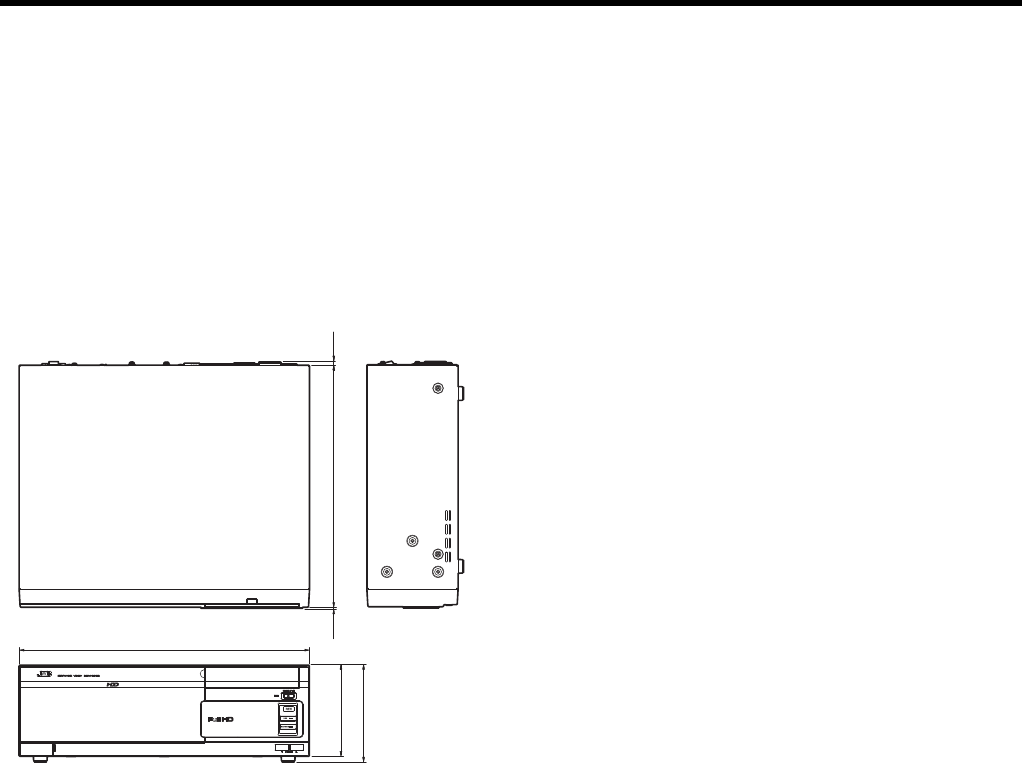
197
䡵Attachments/Accessories
Quick Reference .............................................................. 5
Set Up Guide.................................................................... 1
Power Cord (2.4 m) .......................................................... 1
Power Cord (2 m) ............................................................. 2
Rack Mount Bracket ........................................................ 2
Warranty Card ................................................................. 1
Screw (M4 x 11 mm) ........................................................ 6
Screw (M5 x 10 mm) ........................................................ 4
䡵Dimensional Outline Drawing (Unit: mm)
TThe specifications and appearance of this unit may be
modified for improvement without prior notice.
1.5
132
140
4.7
350
420

Others
198
A
Action .............................................................................. 46
Additional HDD
Connection ..........................................................26, 71
RAID.......................................................................... 72
Archiving
Settings ................................................................... 107
Storage location (Archiving Path)..........36, 76, 96, 100
Audio
Live audio ................................................................145
Recorded audio ....................................................... 154
Automatic switching of multiple camera images
(Carousel) .....................................................................156
C
Camera
Audio settings....................................................95, 124
Camera Properties .................................................... 94
Compatible cameras ............................................... 181
Registration (auto)..................................................... 33
Registration (manual)..............................................117
Shortcut menu ......................................................... 146
Shortcut number................................................94, 100
Camera license ............................................................. 118
Connection
Connection to this unit...............................................26
Network connection...................................................28
CPU meter ....................................................................130
E
E-mail
Notification schedule ...............................................123
Notification setting (Management Application/Smart
Client)..................................................................59, 60
Notification setting (Unit Setting) ............................... 59
eSATA terminal................................................... 21, 26, 71
Event
Generic event (Generic Events)................................46
Input event (Hardware Input Events).........................48
Manual event (Manual Events)..................................50
Timer event ...............................................................51
Export
AVI/JPEG ................................................................ 164
Database ................................................................. 165
Viewer .....................................................................167
F
Floating window ............................................................160
Frame rate
Display frame rate ...........158, 172, 173, 174, 175, 177
Live frame rate ............................................35, 94, 102
Recording frame rate................................... 35, 94, 102
Speedup............................................................94, 102
H
Hardware device
Deletion ...................................................................119
Hardware Properties..................................................92
Replacement ...........................................................118
HDD meter ....................................................................130
Hotspot..........................................................................157
HTML page....................................................................158
I
Image quality.........................158, 172, 173, 174, 175, 177
Indicator
Event indicator.........................................................142
HDD indicator ............................................................20
Live indicator ...........................................................142
Motion indicator .......................................................142
OPERATE indicator...................................................20
REC indicator ............................................................20
WARNING indicator...........................................20, 129
K
Keyboard
Connection ................................................................26
On-screen keyboard ..................................................30
L
Language
Management Application .........................................111
Smart Client.............................................................178
Unit Setting................................................................83
Live image
Camera operation....................................................144
Independent playback .............................................145
Logs
Management Application .................................109, 128
Unit Setting........................................................83, 128
M
Maintenance information...............................................129
Management Application
Advanced Configuration ............................................91
Saving settings ....................................................19, 79
Start up......................................................................32
Wizards..............................................33, 34, 44, 66, 90
Master/slave....................................................................63
Matrix.......................................................53, 109, 173, 179
Mic
Connection ................................................................26
Settings......................................................95, 104, 124
Monitor
Connection ................................................................26
Resolution..........................................................26, 114
Settings............................................................114, 115
Motion detection
Indicator...................................................................142
Recording ............................................................35, 55
Settings......................................................................44
Index

199
N
NAS................................................................................. 75
Network
LAN1 .....................................................28, 31, 84, 119
LAN2 ............................................. 28, 31, 84, 119, 137
Network settings
NVR.....................................................................31, 84
Surveillance PC.......................................................137
O
Operation lock...............................................................116
Overlay buttons............................................................. 160
P
Password
Login password of NVR............................................. 87
Login password of Smart Client ........................66, 133
Operation lock .........................................................116
Startup password of Management Application..........70
PTZ camera
Joystick....................................................................161
Operation.................................................................144
Patrolling .....................................................41, 98, 124
Patrolling schedule .................................................. 124
Preset position.......................................39, 52, 98, 144
R
Recorded image
Export ...................................................................... 164
Independent playback ............................................. 154
Playback.................................................................. 153
Print .........................................................................156
Searching ................................................................149
Recording
Frame rate................................................... 35, 94, 102
Manual recording.....................................................143
REC indicator ............................................................ 20
Recording conditions.................................................35
Recording performance..................................... 37, 182
Schedule ................................................................. 123
Storage location (Recording Path) .............. 36, 96, 100
S
SERIAL terminal ...........................20, 21, 26, 71, 125, 129
Settings
Management Application.....................................90, 91
Network ....................................................... 31, 84, 137
Smart Client..................................................... 171, 176
Unit Setting................................................................ 81
Smart Client
Description .............................................................. 135
Installation ............................................................... 136
Live screen ......................................................142, 169
Options .................................................................... 176
Playback screen ..............................................147, 170
Setting screen ......................................................... 171
Start up....................................................................133
User settings ..................................................... 66, 112
SNMP setting ................................................................126
Speaker
Connection ................................................................26
Settings......................................................95, 104, 124
Still images....................................................................159
Surveillance PC
Installation ...............................................................136
Network settings ......................................................137
System requirements...............................................137
U
UPS...............................................................................125
V
View
Creating ...................................................................139
Editing......................................................................141

NETWORK VIDEO RECORDER
VR-X3200U/VR-X1600U
LST1260-001B© 2012 JVC KENWOOD Corporation
