JVCKENWOOD 371302 VHF Digital base repeater User Manual B62 1994 00 NXR 700 800 indd
JVC KENWOOD Corporation VHF Digital base repeater B62 1994 00 NXR 700 800 indd
Instruction Manual

NXR-700/ NXR-800
INSTRUCTION MANUAL
© B62-1994-00 (K, K2)
09 08 07 06 05 04 03 02 01 00
MANUAL DE INSTRUCCTIONES
MODE D'EMPLOI
BASE-REPETIDOR DIGITAL VHF / BASE-REPETIDOR DIGITAL UHF
VHF DIGITAL BASE-REPEATER/ UHF DIGITAL BASE-REPEATER
BASE-RELAIS NUMÉRIQUE VHF/BASE-RELAIS NUMERIQUE UHF
◆ Thisrepeaterisintendedforuseasaxedbasestationwiththe
antennalocatedoutdoorsontherooftoporonanantennatower.
◆ UseonlythesuppliedDCcord.
◆ DonotremovetheferritecoreattachedtotheDCcord.Doingso
maycauseinterferencewithradiocommunications.
UNPACKING AND CHECKING EQUIPMENT
Note:Thefollowingunpackinginformationisforusebyyour
Kenwood dealer, an authorized Kenwood service center, or the
factory.
Carefullyunpacktherepeater.Werecommendthatyou
identifytheitemslistedinthefollowingtablebeforediscarding
thepackingmaterial.Ifanyitemsaremissingorhave
beendamagedduringshipment,leaclaimwiththecarrier
immediately.
Item Part Number Quantity
Frontglass B10-2781-XX 1
Dressedscrew N08-0563-XX 1
Bracket J29-0725-XX 2
Flatheadmachinescrew N32-4008-XX 4
Handleandscrewset K01-0421-XX 1
DC cord E30-3344-XX 1
Leadwirewithconnector(15pin) E37-1381-XX 1
Fuse(7.5A) F05-7521-XX 1
Instruction Manual B62-1994-XX 1
Serialnumbersticker B42-7325-XX 1
INSTALLATION
Toinstallthehandlesontothefrontpaneloftherepeater,align
thehandleswiththeholesonthefrontpanel,thensecurethe
handlesusingthesuppliedscrews.
Pleaseconsultyourdealerforinstallingtherepeaterand
antenna.
MICROPHONE
Connect an optional KMC-30, KMC-35, or KMC-9C Kenwood
microphone to the MICROPHONEjackonthefrontpanel.
NOTICES TO THE USER
FCC WARNING
Thisequipmentgeneratesorusesradiofrequencyenergy.Changes
ormodicationstothisequipmentmaycauseharmfulinterference
unlessthemodicationsareexpresslyapprovedintheinstruction
manual.Theusercouldlosetheauthoritytooperatethisequipmentif
anunauthorizedchangeormodicationismade.
◆ Governmentlawprohibitstheoperationofunlicensedradio
transmitterswithintheterritoriesundergovernmentcontrol.
◆ Illegaloperationispunishablebyneand/orimprisonment.
◆ Referservicetoqualiedtechniciansonly.
THANK YOU!
WearegratefulyoupurchasedthisKenwoodrepeater.We
believethiseasy-to-programrepeaterwillbehighlyeffectivein
yourcommunicationssystem,andwillkeeppersonneloperating
atpeakefciency.
Kenwoodincorporatesthelatestinadvancedtechnologyinto
allofourproducts.Asaresult,wefeelstronglythatyouwillbe
pleasedwiththequalityandfeaturesofthisproduct.
PRECAUTIONS
• Donotexposetheunittorainormoisture;topreventreor
electricshock.
• Donotopentheunitunderanycircumstances;toavoidrisk
ofelectricshock.
• Donotexposetheunittolongperiodsofdirectsunlight,nor
placeitclosetoheatingappliances.
• Donotplacetheunitinexcessivelydustyand/orhumid
areas,noronunstablesurfaces.
• Ifyoudetectanabnormalodororsmokecomingfromthe
unit,disconnectthepowerfromtheunitimmediately.Contact
your Kenwood servicecenterordealer.
NXR-700 / NXR-800 INSTRUCTION MANUAL
VHF DIGITAL BASE-REPEATER / UHF DIGITAL BASE-REPEATER
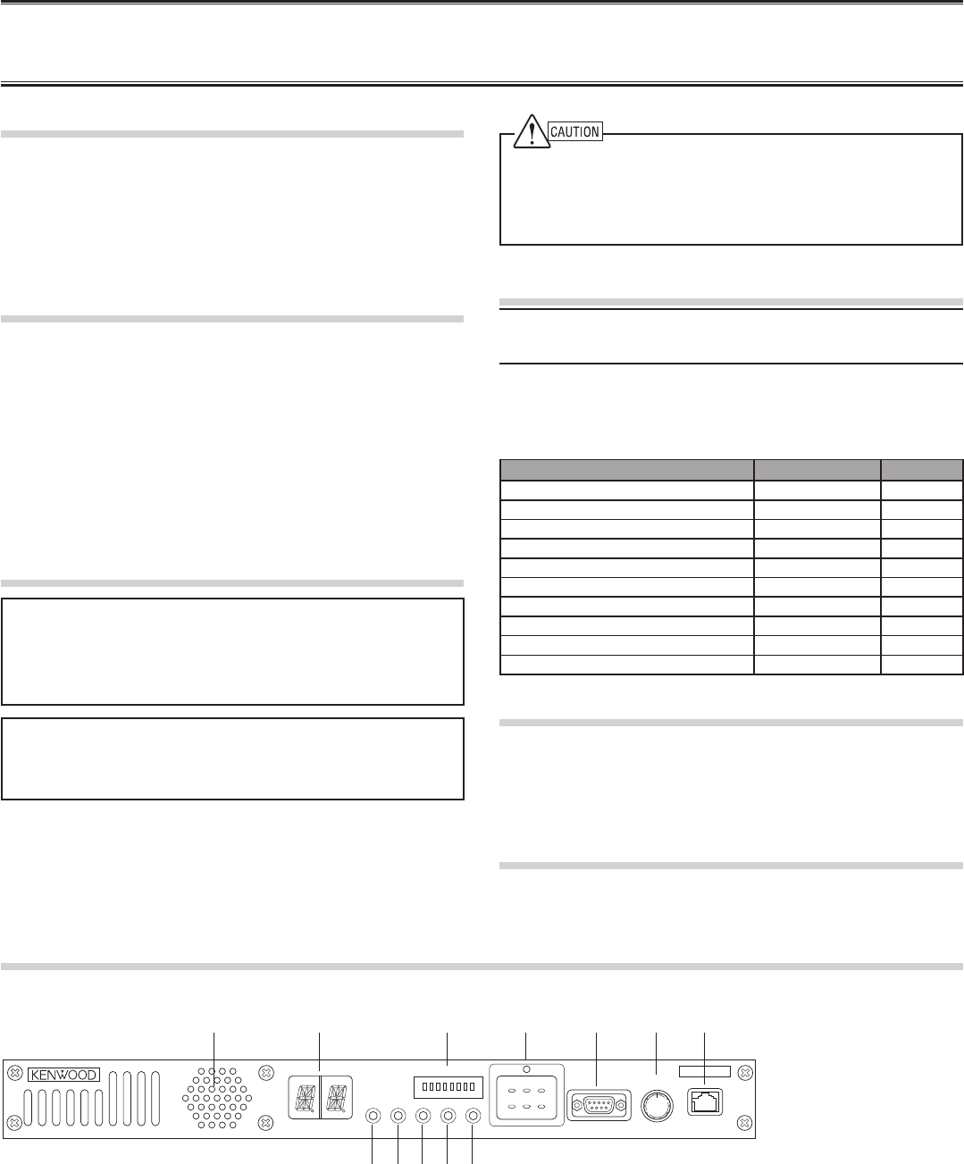
q Speaker
w CH/STATUS Display
Two17-segmentdigitsdisplaythechannelnumber,
name,orstatus.
e STATUS indicator
Indicatesthestatusoftherepeater.
r Programmable Function keys
Pressthesekeystoactivatetheirprogrammable
functions.
CONTROLS AND FUNCTIONS
■ Front Panel
qw r t y u
io
e
MICROPHONE
VOLUME
COM OFF/
POWERCTRL OCXO BUSY TX
1 2
MON
TAKE
OVER
RPT
DISABLE
A B C
3 4 5 6 7 8
STATUS
t COM jack
ConnecttoPC.ConformtoRS-232Cstandard.
y VOLUME control
Turnclockwiseuntilaclicksounds,tounmutethevolume.
Rotatetoadjustthevolume.Turncounterclockwisefully
tomutethevolume.
u MICROPHONE jack
Connectamicrophonetothis8-pinmodularjack.
!0
!1
!2
REPEATER OPERATION
Note:Pleaseconsultyourdealerforprogrammingtherepeater.
WheoperatingtherepeaterusinganoptionalOCXOunit,allowthe
unittowarmupfor24hoursafterturningthepoweron.
Whenpowerisappliedtotheunit,thePOWERindicatorlights
green.
Turn the VOLUMEcontrolclockwiseuntilaclicksounds,to
unmutethevolume.Rotatetoadjustthevolume.Turnthe
VOLUMEcontrolcounterclockwisefullytomutethevolume
The BUSYindicatorlightsgreenwhilereceivingasignalandthe
TXindicatorlightsredwhiletransmitting.
TRANSCEIVER OPERATION
■ Receive
Adjustthevolumetoyourdesiredlevel.Youmayneedto
readjustthevolumewhenyoureceiveamessagefromyour
dispatcheroranothermemberinyoureet.
• The BUSYindicatorlightsgreenwhileasignalisbeing
received.
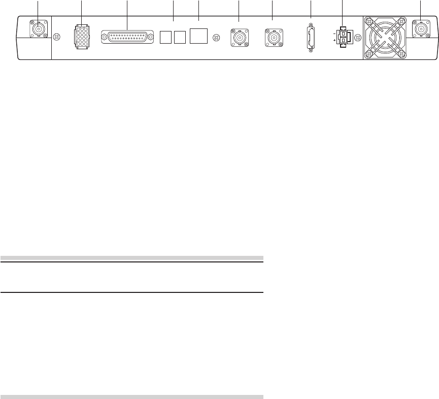
■ Rear Panel
q RX IN jack
ConnectanRXantennaoraduplexertothisBNC
receptacle.
w TEST/SPKR jack
Testinput/outputjack.Connectanexternalspeakerto
thisjack.
e CONTROL I/O jack
ConnectanrepeatercontrollertothisDB-25interface.
r SYNC 1/2 jack
Connect to other repeater to use synchronous frame
signal.
t LAN jack
ConnecttoEthernet.
qwr t yu
e
TEST/SPKR
RX TX
CONTROL I/O SYNC
1 2 LAN REF OUT REF IN
FUSE
75
DC 13.8V
y REF OUT jack
Connecttoanotherrepeaterwithinthesitetosupplya
referencesignal.
u REF IN jack
Connectfromanotherrepeaterwithinthesitetoreceivea
referencesignal.
i FUSE
Insert7.5Abladefusesintothesefuseholders.
o DC 13.8V jack
Connecta13.8VDCpowersupplytothisjack.
⑩ TX OUT jack
ConnectaTXantennaoraduplexertothisreceptacle.
io⑩
■ Transmit
1 Listentothechannelbeforetransmitting,tomakesureit
isnotbeingused.
2 Press the microphone PTTswitch,thenspeakinyour
normalspeakingvoice.
• The TXindicatorlightsredwhiletransmitting.
3 Whenyounishspeaking,releasethePTTswitch.
i POWER indicator
LightsgreenwhenpowerissuppliedtotheDC 13.8V
jack.Blinkswhenanabnormalvoltageispresent.
o TX indicator
Lightsredwhiletransmitting.
!0 BUSY indicator
Lightsgreenwhileasignalisbeingreceived.
!1 OCXO indicator
TheOCXOindicatorshowsthestateofthereference
10 MHz oscillator :
LightsGreenwhenusingareferencesignalfroman
optionalOCXOunit.
LightsOrangewhenusingareferencesignalfromanother
repeater.
Lightsredwhennoreferencesignalisavailableorwhen
anerroroccurs.
Doesnotlightwhenthereferencesignalisaninternal
VCXOsignal.
!2 CTRL indicator
TheCTRLindicatorshowstheRCCHstatuswhileusing
Digitaltrunking:
LightsGreenwhentherepeaterisusedasRCCH.
BlinksGreenwhenusinganon-dedicatedchannel,and
RCCHisusedasRDCH.
DoesnotlightwhenusingRDCH.

UNITE OCXO
KXK-3
MODE D'EMPLOI © B62-2022-00 (M)
09 08 07 06 05 04 03 02 01 00
OCXO UNIT
KXK-3
INSTRUCTION MANUAL
PRECAUTIONS
• Do not drop the unit.
• Aviod jarring the unit, causing vibrations or strong impacts.
•Donotexposetheunittorainormoisture;topreventreorelectricshock.
•Donotopentheunitunderanycircumstances;toavoidriskofelectricshock.
•Donotexposetheunittolongperiodsofdirectsunlight,norplaceitclosetoheatingappliances.
•Donotplacetheunitinexcessivelydustyand/orhumidareas,noronunstablesurfaces.
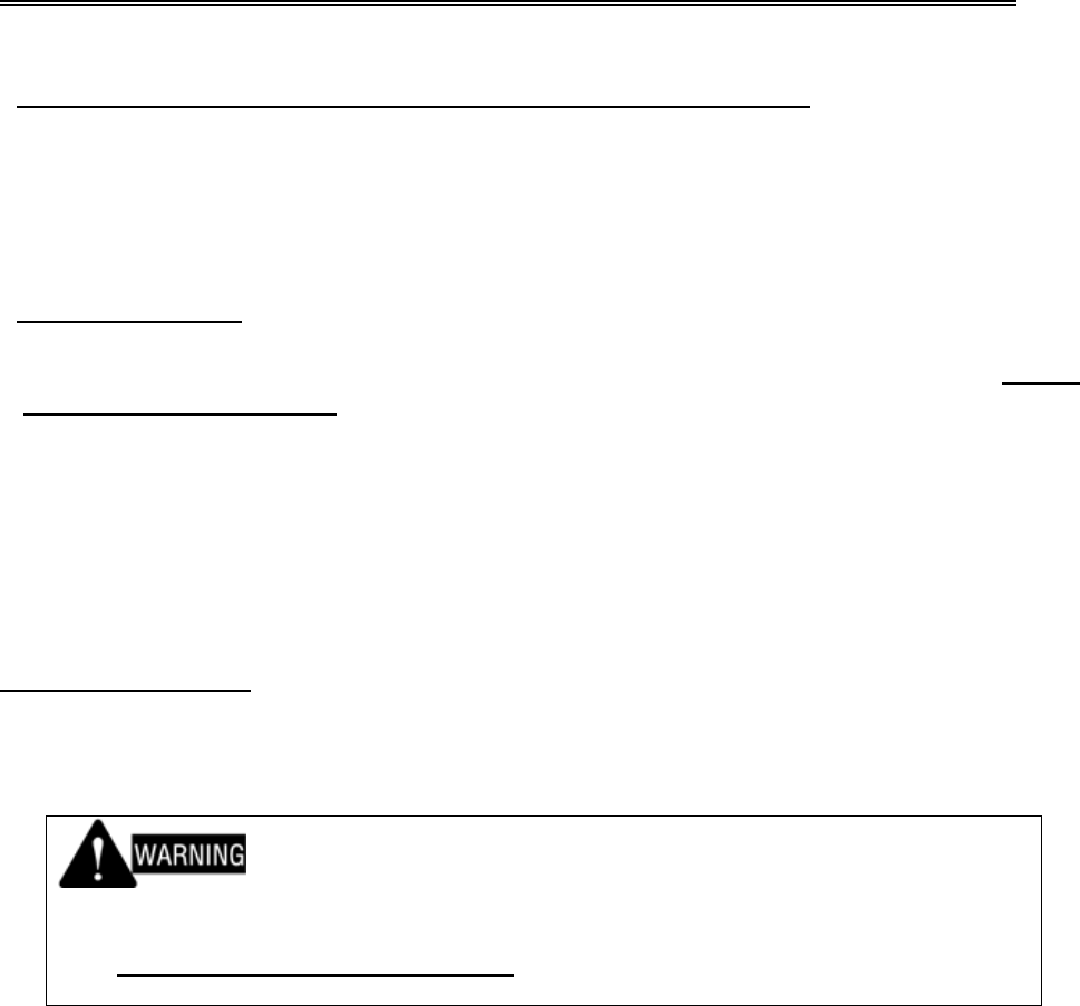
NOTICES TO THE USER
FCC WARNING
Thisequipmentgeneratesorusesradiofrequencyenergy.Changesormodicationstothis
equipmentmaycauseharmfulinterferenceunlessthemodicationsareexpresslyapprovedinthe
instructionmanual.Theusercouldlosetheauthoritytooperatethisequipmentifanunauthorized
changeormodicationismade.
◆ Governmentlawprohibitstheoperationofunlicensedradiotransmitterswithintheterritories
undergovernmentcontrol.
◆ Illegaloperationispunishablebyneand/orimprisonment.
◆ Referservicetoqualiedtechniciansonly.
UNPACKING AND CHECKING EQUIPMENT
Note:ThefollowingunpackinginformationisforusebyyourKenwooddealer,anauthorizedKen-
woodservicecenter,orthefactory.
Carefullyunpacktheunit.Werecommendthatyouidentifytheitemslistedinthefollowing
tablebeforediscardingthepackingmaterial.Ifanyitemsaremissingorhavebeen
damagedduringshipment,leaclaimwiththecarrierimmediately.
Item Part Number Quantity
PanheadsemsscrewW N67-3008-XX 5
Flatcable E37-1405-XX 1
Leadwirewithminipinplug E31-3269-XX 1
Leadwirewithconnector E37-1406-XX 1
InstructionManual B62-2022-XX 1
INSTALLATION
PleaseconsultyourdealerforinstallingtheOCXOunit.
Note:WheninstallingtheOCXOunit,besuretonotethedirectionoftheunit.
UNIDAD OCXO
KXK-3
MANUAL DE INSTRUCCTIONES
ThisdevicecomplieswithPart15oftheFCCRules.Operationissubjecttothefollowingtwo
conditions:
(1) thisdevicemaynotcauseharmfulinterference,and
(2) thisdevicemustacceptanyinterferencereceived,includinginterferencethatmaycause
undesired operation.
Oneormoreofthefollowingstatementsmaybeapplicabletothisequipment.
Authorized Representative:
Kenwood Electronics Europe B.V
Amsterdamseweg 37, 1422 AC Uithoorn, Netherlants
MANDATORY SAFETY INSTRUCTIONS TO INSTALLERS AND USERS
• Use only manufacturer or dealer supplied antenna.
• Antenna Minimum Safe Distance: 60 cm (2 feet), 50% duty Cycle.
• Antenna Gain: 0 dBd referenced to a dipole.
The Federal Communications Commission has adopted a safety standard for human
exposure to RF (Radio Frequency) energy which is below the OSHA (Occupational Safety
and Health Act) limits.
• Antenna Mounting: The antenna supplied by the manufacturer or radio dealer must not be
mounted at a location such that during radio transmission, any person or persons can
come closer than the above indicated minimum safe distance to the antenna, i.e. 60 cm
(2 feet) , 50% duty Cycle.
• To comply with current FCC RF Exposure limits, the antenna must be installed at or
exceeding the minimum safe distance shown above, and in accordance with the
requirements of the antenna manufacturer or supplier.
• Vehicle installation: The antenna can be mounted at the center of a vehicle metal roof or
trunk lid, if the minimum safe distance is observed.
• Base Station Installation: The antenna should be fixed-mounted on an outdoor permanent
structure. RF Exposure compliance must be addressed at the time of installation.
Antenna substitution: Do not substitute any antenna for the one supplied or recommended
by the manufacturer or radio dealer.
You may be exposing person or persons to excess radio frequency radiation. You may
contact your radio dealer or the manufacturer for further instructions.
Maintain a separation distance from the antenna to person(s) of at least
60 cm (2 feet) , 50% duty Cycle.
You, as the qualified end-user of this radio device must control the exposure conditions of
bystanders to ensure the minimum separation distance (above) is maintained between the
antenna and nearby persons for satisfying RF Exposure compliance. The operation of this
transmitter must satisfy the requirements of Occupational/Controlled Exposure
Environment, for work-related use, transmit only when person(s) are at least the minimum
distance from the properly installed, externally mounted antenna. Transmit only when
people outside the vehicle are at least the recommended minimum lateral distance away
from the antenna/vehicle