JVCKENWOOD 397700 Scanning Receiver User Manual Instruction Manual 1
JVC KENWOOD Corporation Scanning Receiver Instruction Manual 1
Contents
- 1. Instruction Manual 1
- 2. Instruction Manual 2
- 3. User Manual
- 4. User Instructions Guide
- 5. User Guide Instructions
Instruction Manual 1

INSTRUCTION MANUAL
144/440 MHz FM DUAL BANDER
TM-V71A
144/430 MHz FM DUAL BANDER
TM-V71A/ TM-V71E
© B62-1926-00 (K, E, M4)
09 08 07 06 05 04 03 02 01 00
Information on Disposal of Old Electrical and Electronic
Equipment (applicable for EU countries that have
adopted separate waste collection systems)
Products with the symbol (crossed-out wheeled bin) cannot be
disposed as household waste.
Old electrical and electronic equipment should be recycled at a
facility capable of handling these items and their waste byproducts.
Contact your local authority for details in locating a recycle facility
nearest to you. Proper recycling and waste disposal will help
conserve resources whilst preventing detrimental effects on our
health and the environment.

Thank You
We are grateful you decided to purchase this Kenwood FM transceiver.
Kenwood always provides Amateur Radio products which surprise and excite
serious hobbyists. This transceiver is no exception. Kenwood believes that this
product will satisfy your requirements for both voice and data communications.
FeaTures
This transceiver has the following main features:
• Enhanced Programmable Memory (PM) channels store virtually entire current operating
environments for your quick recall.
• Contains a total of 1000 Memory channels to program frequencies and other various
data. Allows each Memory channel to be named using up to 8 alphanumeric characters.
• Continuous Tone Coded Squelch System (CTCSS) or Digital Code Squelch (DCS)
rejects unwanted calls from other stations.
WriTing ConvenTions FolloWed in This Manual
The writing conventions described below have been followed to simplify
instructions and avoid unnecessary repetition.
Instruction Action
Press [KEY]. Momentarily press KEY.
Press [KEY] (1s). Press and hold KEY for 1 second or longer.
Press [KEY1], [KEY2]. Press KEY1 momentarily, release KEY1, then press
KEY2.
Press [F], [KEY]. Press the F key to enter Function mode, then press
KEY to access its secondary function.
Press [KEY] + Power ON. With the transceiver power OFF, press and hold
KEY while turning the transceiver power ON.

i
Notices to the User
One or more of the following statements may be applicable:
FCC WARNING
This equipment generates or uses radio frequency energy. Changes or modications to this
equipment may cause harmful interference unless the modications are expressly approved in the
instruction manual. The user could lose the authority to operate this equipment if an unauthorized
change or modication is made.
INFORMATION TO THE DIGITAL DEVICE USER REQUIRED BY THE FCC
This equipment has been tested and found to comply with the limits for a Class B digital device,
pursuant to Part 15 of the FCC Rules. These limits are designed to provide reasonable protection
against harmful interference in a residential installation.
This equipment generates, uses and can generate radio frequency energy and, if not installed and
used in accordance with the instructions, may cause harmful interference to radio communications.
However, there is no guarantee that the interference will not occur in a particular installation. If
this equipment does cause harmful interference to radio or television reception, which can be
determined by turning the equipment off and on, the user is encouraged to try to correct the
interference by one or more of the following measures:
• Reorient or relocate the receiving antenna.
• Increase the separation between the equipment and receiver.
• Connect the equipment to an outlet on a circuit different from that to which the receiver is
connected.
• Consult the dealer for technical assistance.
WHEN CONDENSATION OCCURS INSIDE THE TRANSCEIVER
Condensation may occur inside the transceiver in such a case where the room is warmed using a
heater on cold days or where the transceiver is quickly moved from a cold room to a warm room.
When condensation occurs, the microcomputer and/or the transmit/receive circuits may become
unstable, resulting in transceiver malfunction. If this happens, turn OFF the transceiver and just
wait for a while. When the condensation droplets disappear, the transceiver will function normally.
u EXPLOSIVE ATMOSPHERES (GASES, DUST, FUMES, etc.)
Turn OFF your transceiver while taking on fuel or while parked in gasoline service stations. Do
not carry spare fuel containers in the trunk of your vehicle if your transceiver is mounted in the
trunk area.
u INJURY FROM RADIO FREQUENCY TRANSMISSIONS
Do not operate your transceiver when somebody is either standing near to or touching the
antenna, to avoid the possibility of radio frequency burns or related physical injury.
u DYNAMITE BLASTING CAPS
Operating the transceiver within 150 m (500 feet) of dynamite blasting caps may cause them
to explode. Turn OFF your transceiver when in an area where blasting is in progress, or where
“TURN OFF TWO-WAY RADIO” signs have been posted. If you are transporting blasting caps
in your vehicle, make sure they are carried in a closed metal box with a padded interior. Do not
transmit while the caps are being placed into or removed from the container.
ii
PrecaUtioNs
Observe the following precautions to prevent re, personal injury, and transceiver
damage.
• When operating mobile, do not attempt to congure the transceiver while driving; it is
too dangerous.
• Do not transmit with high output power for extended periods. The transceiver may
overheat.
• Do not disassemble or modify the transceiver for any reason, unless instructed by this
manual or by Kenwood documentation.
• Do not expose the transceiver to long periods of direct sunlight, nor place it near heating
appliances.
• Do not place the transceiver in excessively dusty, humid, or wet areas, nor on unstable
surfaces.
• If an abnormal odor or smoke is detected coming from the transceiver, switch the
transceiver power off immediately, and contact a Kenwood service station or your
dealer.
• Use of the transceiver while you are driving may be against trafc laws. Please check
and observe the vehicle regulations in your area.
• Be aware of local laws pertaining to the use of headphones/headsets while driving on
public roads. If in doubt, do not wear a headset while mobiling.
• Do not use options not specied by Kenwood.
u The transceiver is designed for a 13.8 V DC (±15%) power source! Never use a 24 V battery
to power the transceiver. Check the battery polarity and voltage of the vehicle before installing
the transceiver.
u Use only the supplied DC power cable or a Kenwood optional DC power cable.
u Do not insert metal objects into the cooling fan.
u Do not cut and/or remove the fuse holder on the DC power cable. Improper connections and/or
current surges may cause smoke or re.
u For passenger safety, install the transceiver securely using the supplied mounting bracket and
screw set so the transceiver will not break loose in the event of a collision.

iii
coNteNts
PREPARATION ...................................................................................1
SUPPLIED ACCESSORIES ...........................................................1
MOBILE INSTALLATION ...............................................................1
POWER CABLE CONNECTION ....................................................2
ANTENNA CONNECTION ..............................................................5
FRONT PANEL ORIENTATION .....................................................6
ACCESSORY CONNECTIONS ......................................................7
GETTING ACQUAINTED .....................................................................8
FRONT PANEL ...............................................................................8
DISPLAY .......................................................................................10
REAR PANEL ...............................................................................12
SUB-PANEL .................................................................................12
MICROPHONE (MC-59) ...............................................................13
BASIC OPERATIONS ........................................................................14
SWITCHING THE POWER ON/ OFF ...........................................14
ADJUSTING THE VOLUME .........................................................14
ADJUSTING THE SQUELCH .......................................................15
SELECTING A BAND ...................................................................15
SELECTING DUAL BAND MODE/ SINGLE BAND MODE .........16
SELECTING A FREQUENCY BAND ...........................................17
SELECTING AN OPERATING MODE .........................................17
TRANSMITTING ...........................................................................19
MENU MODE .....................................................................................20
MENU ACCESS ............................................................................20
MENU CONFIGURATION ............................................................20
CHARACTER ENTRY ..................................................................24
OPERATING THROUGH REPEATERS ............................................26
REPEATER ACCESS ...................................................................26
TRANSMITTING A 1750 Hz TONE ..............................................30
REVERSE FUNCTION ..................................................................30
AUTOMATIC SIMPLEX CHECKER (ASC) ..................................30
TONE FREQUENCY ID ................................................................31

iv
MEMORY CHANNELS ......................................................................32
SIMPLEX & REPEATER OR ODD-SPLIT
MEMORY CHANNEL? .................................................................32
STORING SIMPLEX AND STANDARD REPEATER
FREQUENCIES ............................................................................33
STORING ODD-SPLIT REPEATER FREQUENCIES ..................33
RECALLING A MEMORY CHANNEL ..........................................34
CLEARING A MEMORY CHANNEL ............................................35
NAMING A MEMORY CHANNEL ................................................35
SWITCHING THE MEMORY NAME/ FREQUENCY DISPLAY ....36
MEMORY-TO-VFO TRANSFER ...................................................36
CHANNEL DISPLAY FUNCTION .................................................36
PROGRAMMABLE MEMORY (PM) ..................................................38
PROGRAMMABLE INFORMATION ............................................38
APPLICATION EXAMPLES .........................................................39
STORING DATA IN PM CHANNELS ...........................................40
RECALLING PM CHANNELS ......................................................40
AUTO PM CHANNEL STORE ......................................................41
PM CHANNEL RESET .................................................................41
SCAN .................................................................................................42
SELECTING A SCAN RESUME METHOD ..................................43
VFO SCAN ....................................................................................43
MEMORY SCAN ...........................................................................44
GROUP SCAN ..............................................................................45
PROGRAM SCAN ........................................................................46
MHz SCAN ....................................................................................48
CALL SCAN ..................................................................................48
CONTINUOUS TONE CODED SQUELCH SYSTEM (CTCSS) ........49
USING CTCSS ..............................................................................49
CTCSS FREQUENCY ID ..............................................................51
DIGITAL CODED SQUELCH (DCS) ..................................................52
USING DCS ..................................................................................52
DCS CODE ID ...............................................................................54
DUAL TONE MULTI-FREQUENCY (DTMF) .....................................55
MANUAL DIALING .......................................................................55

v
AUTOMATIC DIALER ..................................................................56
DTMF KEY LOCK .........................................................................58
EchoLink MEMORY ..........................................................................59
AUTOMATIC DIALER ..................................................................59
SETTING UP EchoLink MODE ....................................................61
AUXILIARY FUNCTIONS ..................................................................62
POWER-ON MESSAGE ...............................................................62
DISPLAY BRIGHTNESS ..............................................................62
KEY LOCK ....................................................................................63
KEY BEEP ....................................................................................64
PROGRAMMABLE VFO ..............................................................64
CHANGING THE FREQUENCY STEP SIZE ................................65
PROGRAMMABLE FUNCTION KEYS ........................................66
FREQUENCY DIRECT ENTRY ....................................................67
AUTOMATIC POWER OFF (APO) ...............................................67
S-METER SQUELCH ....................................................................68
ADVANCED INTERCEPT POINT (AIP) .......................................68
SWITCHING FM/AM MODE .........................................................69
BEAT SHIFT .................................................................................69
SPEAKER MUTE ..........................................................................69
SELECTING AN OUTPUT POWER .............................................70
TIME-OUT TIMER (TOT) ..............................................................70
EXTERNAL SPEAKER CONFIGURATION .................................71
MASKING A BAND ......................................................................71
DISPLAY PARTITION BAR ..........................................................72
WEATHER ALERT (K TYPE MODELS ONLY)............................73
PASSWORD PROTECTION .........................................................74
VGS-1 OPTIONAL VOICE GUIDE & STORAGE UNIT .....................75
VOICE ANNOUNCEMENTS .........................................................75
VOICE RECORDER ......................................................................78
CROSS-BAND/ LOCKED-BAND OPERATION
(K TYPE MODELS ONLY) .................................................................81
REPEATER HOLD ........................................................................82
REPEATER ID ..............................................................................82

vi
Packet OPeratiOn ......................................................................83
Data BanD .................................................................................83
Data terminal SPeeD ............................................................83
Pc POrt SPeeD .........................................................................84
SQc OutPut Setting ..............................................................84
WireleSS OPeratiOn (k tyPe mODelS Only) .......................85
PreParatiOn ............................................................................85
cOntrOl OPeratiOn ..............................................................86
tranSceiver reSet .....................................................................87
OPtiOnS ...........................................................................................89
cOnnecting the Pg-5g/ Pg-5h interface caBleS........90
inStalling the Dfk-3D Panel kit ......................................90
cOnnecting the Pg-5f extenSiOn caBle .......................92
inStalling the vgS-1 vOice guiDe unit ...........................93
maintenance .................................................................................94
general infOrmatiOn ..........................................................94
Service .......................................................................................94
Service nOte ............................................................................94
cleaning ....................................................................................94
trOuBleShOOting ..................................................................95
SPecificatiOnS .............................................................................96
1
PREPARATION
SUPPLIED ACCESSORIES
Note: A market area code (K, E, or M4) can be found on the label attached to the package box.
Item Part Number Quantity
Microphone T91-0657-XX 1
DC power cable
(with 20 A fuses)
K, M4 types E30-7628-XX 1
E type E30-3452-XX 1
Mounting bracket J29-0628-XX 1
Screw set N99-0331-XX 1
Fuse (15 A) K, M4 types F51-0079-XX 1
E type F52-0024-XX 1
Warranty Card K, E types only —— 1
Instruction manual B62-1926-XX 1
MOBILE INSTALLATION
Select a safe, convenient location inside your vehicle that will minimize danger to
your passengers and yourself while the vehicle is in motion. Consider installing
the transceiver under the dash in front of the passenger seat so that knees or legs
will not strike the radio during sudden braking of your vehicle. Try to a pick
well-ventilated location that is shielded from direct sunlight.
Note: You may experience interference on your GPS receiver when using in or around 438.8 MHz
(A band) and/or 443.8 MHz (B band). To eliminate the interference, ensure that the transceiver is
installed at a location separate from your GPS receiver.
1 Install the mounting bracket in the vehicle using the supplied self-tapping
screws and at washers (4 of each are supplied).
• The bracket can be mounted with the bracket opening facing down, for underdash
mounting, or facing up.
• The bracket must be installed so that the 3 screw slots on the edge of each bracket
side are facing the back.
Self-tapping screw
(5 x 16 mm)
Flat washer
2
2 Position the transceiver, then insert and tighten the supplied hexagon SEMS
screws and at washers (4 of each are supplied, 2 for each side of the
bracket).
• Ensure that all hardware is tightened, to prevent vehicle vibration from loosening the
bracket or transceiver.
• Set an appropriate angle for the main unit, using the 3 screw slots on the rear edge
of each bracket side.
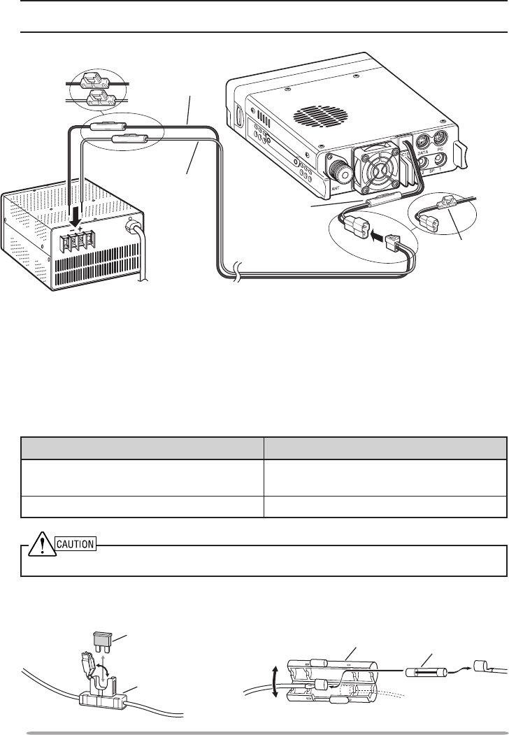
POWER CABLE CONNECTION
n Mobile Operation
Be sure to use a 12 V vehicle battery that has sufcient current capacity. If
the current to the transceiver is insufcient, the display may darken during
transmission or the transmit output power may drop excessively. Never
connect the transceiver to a 24 V battery
Note: If you use the transceiver for a long period when the vehicle battery is not fully charged
or when the engine is OFF, the battery may become discharged and will not have sufcient
reserves to start the vehicle. Avoid using the transceiver under these conditions.
1 Route the DC power cable supplied with the transceiver directly to the
vehicle’s battery terminals using the shortest path from the transceiver.
• When using a noise lter, it should be installed with an insulator to prevent it from
touching metal on the vehicle.
• We do not recommend using a cigarette lighter socket as some cigarette lighter
sockets introduce an unacceptable voltage drop.
• If the power cable must be routed through a hole in the vehicle chassis or body,
for example in the rewall at the front of the passenger compartment, use a
rubber grommet to protect the cable from abrasion. Dismantle the fuse holder to
pass the cable through the rewall.
• The entire length of the cable must be dressed so it is isolated from heat,
moisture, and the engine secondary (high voltage) ignition system/ cables.
SEMS screw
3
2 After the cable is in place, wind heat-resistant tape around the fuse holder
to protect it from moisture. Tie down the full run of cable.
3 To prevent the risk of short circuits, disconnect other wiring from the
negative (–) battery terminal before connecting the transceiver.
4 Conrmthecorrectpolarityoftheconnections,thenattachthepowercable
to the battery terminals; red connects to the positive (+) terminal and black
connects to the negative (–) terminal.
• Use the full length of the cable without cutting off excess, even if the cable is
longer than required. In particular, never remove the fuse holders from the cable.
5 Reconnect any wiring removed from the negative terminal.
6 Connect the DC power cable to the transceiver.
• Presstheconnectorsrmlytogetheruntilthelockingtabclicks.
Passenger compartment
Engine compartment
Black (—) cable
Red (+)
cable
Rubber grommet
Fuse holder (E type)
Fuse holder
(K, M4 types)
Fuse holder
(K, M4 types)
Fuse holder
(E type)
12 V vehicle
battery
DC power cable
n Fixed Station Operation
Inordertousethistransceiverforxedstationoperation,youwillneeda
separate 13.8 V DC power supply that must be purchased separately. The
recommended current capacity of the power supply is 12 A.
Note: Do not plug the DC power supply into an AC outlet until you make all connections.
1 Ensure that the transceiver and DC power supply are both OFF.
2 Connect the DC power cable to the regulated DC power supply and ensure
that the polarities are correct (Red: positive, Black: negative).
• Use the supplied DC power cable to connect the transceiver to a regulated
power supply. Do not directly connect the transceiver to an AC outlet.
• Do not substitute the cable with smaller gauge wires.
4
3 Connect the DC power cable to the transceiver.
• Presstheconnectorsrmlytogetheruntilthelockingtabclicks.
Note: For your transceiver to fully exhibit its performance capabilities, we recommend using
an optional PS-33 (20.5 A, 25% duty cycle) power supply.
n Replacing Fuses
If the fuse blows, determine the cause, then correct the problem. After the
problem is resolved, replace the fuse. If newly installed fuses continue to
blow, disconnect the power cable and contact your authorized Kenwood
dealer or an authorized Kenwood service center for assistance.
Fuse Location Fuse Current Rating
Transceiver
(located on the DC connector) 15 A
Supplied DC power cable 20A
Onlyusefusesofthespeciedtypeandrating;otherwisethetransceivercouldbedamaged.
Black (—)
cable
Red (+)
cable
DC power cable
Fuse holder
(K, M4 types)
Fuse holder
(E type)
Fuse holder (E type)
Fuse holder
(K, M4 types)
Regulated DC
power supply
Fuse holder (E type) Fuse holder (K, M4 types)
Fuse
Fuse holder
Fuse holder Fuse
5
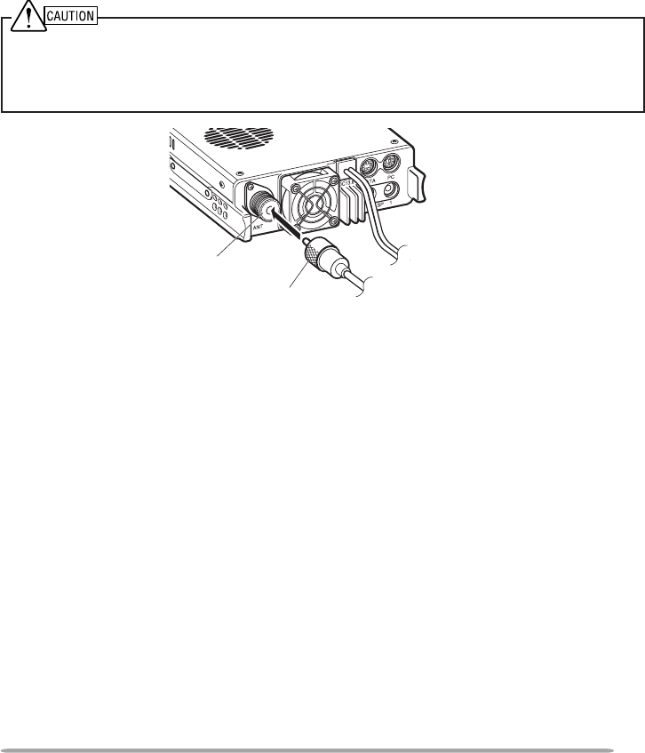
ANTENNA CONNECTION
Before operating, you must rst install an efcient, well-tuned antenna. The
success of your installation will depend largely on the type of antenna and its
correct installation. The transceiver can give excellent results if the antenna
system and its installation are given careful attention.
Use a low-loss coaxial feed line that also has a characteristic impedance of
50 Ω, to match the transceiver input impedance. Coupling the antenna to the
transceiver via feed lines having an impedance other than 50 Ω reduces the
efciency of the antenna system and can cause interference to nearby broadcast
television receivers, radio receivers, and other electronic equipment.
u Transmitting without rst connecting an antenna or other matched load may damage the
transceiver. Always connect the antenna to the transceiver before transmitting.
u All xed stations should be equipped with a lightning arrester to reduce the risk of re, electric
shock, and/or transceiver damage.
To antenna
Antenna
terminal
Feed line
connector
6
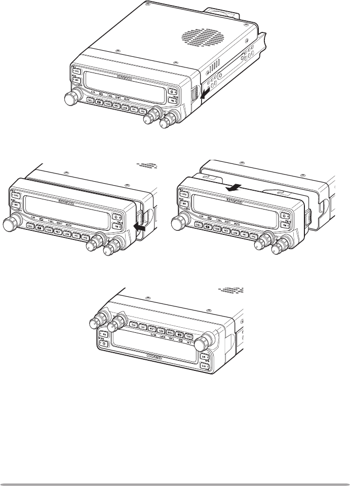
FRONT PANEL ORIENTATION
This transceiver allows you to change the orientation of the front panel.
Depending on where/how you installed the transceiver you may wish to ip the
front panel upside-down for easier operation.
1 On the right side of the front panel, pull the panel release latch forward.
2 Slide the front panel to the left, then pull it away from the main body of the
transceiver.
3 Flip the front panel upside-down, then reattach it to the main body of the
transceiver.
7
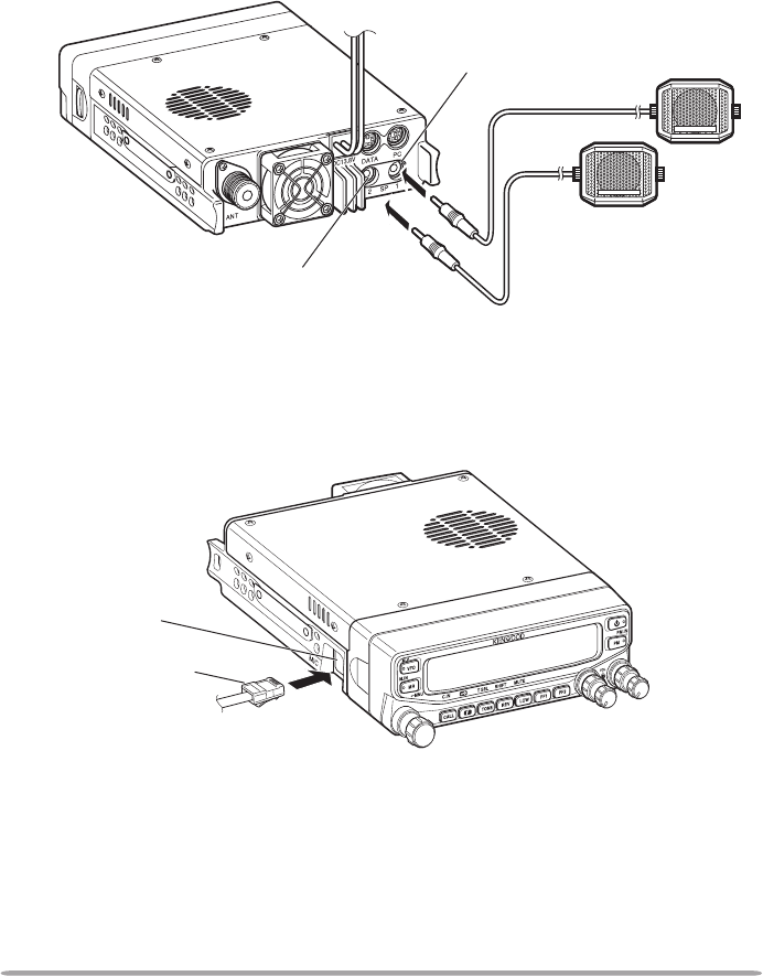
ACCESSORY CONNECTIONS
n External Speakers
If you plan to use external speakers, choose speakers with an impedance of
8 Ω. The external speaker jacks accept a 3.5 mm (1/8”) mono (2-conductor)
plug. We recommend using SP-50B speakers.
There are 2 speaker jacks on the rear of the transceiver: SP 1 and SP 2.
Refer to page 71 to determine how the speakers will be used.
n Microphone
To communicate using voice, connect the supplied microphone to the MIC jack
on the left side of the transceiver. Press rmly on the plug until the locking tab
clicks.
SP 1 jack
SP 2 jack
External speakers (SP-50B)
Microphone
connector
MIC jack
8
GETTING ACQUAINTED
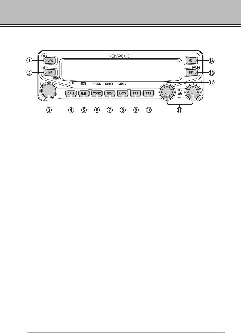
FroNT PANEl
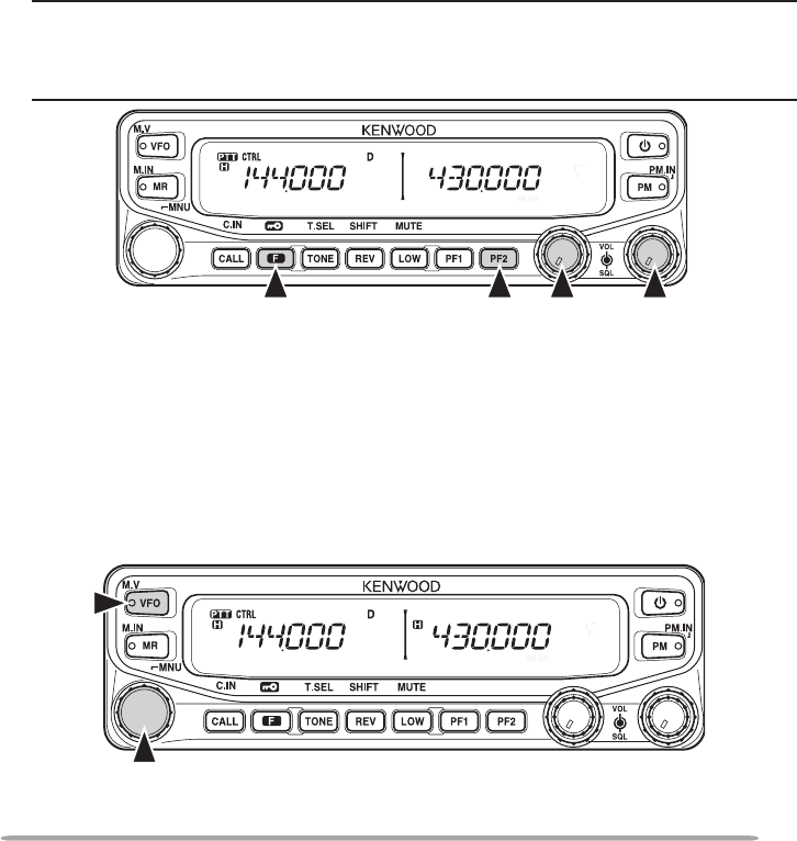
q VFO
Press [VFO] to enter VFO mode {page 17}, then rotate the Tuning control to
select an operating frequency. Press [VFO] (1s) to start VFO scan
{page 43}. Press [F], [VFO] to copy the current Memory channel or Call
channel to the VFO (memory shift) {page 36}.
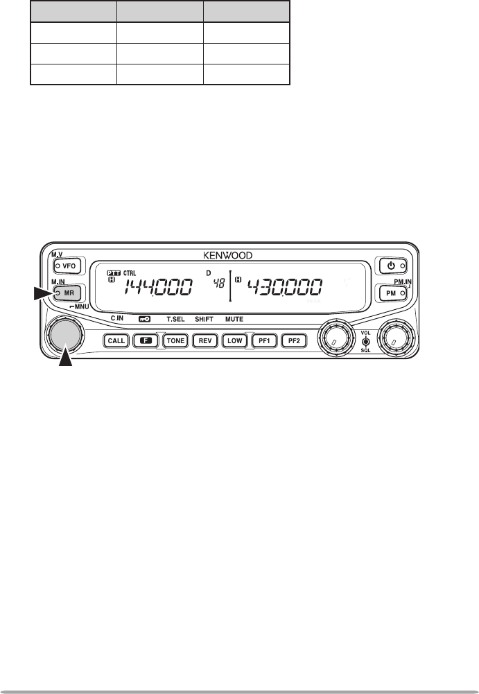
w MR
Press [MR] to enter Memory Channel mode {page 18}, then rotate the Tuning
control to select a Memory channel. Press [MR] (1s) to start Memory scan
{page 44}. Select a Memory channel, then press [F], [MR] to store the current
operating frequency in the Memory channel {page 33}.
e Tuning Control
Rotate to select an operating frequency or Memory channel, change the scan
direction, select a tone frequency, etc. Press [F], then press the Tuning
control to enter Menu mode {page 20}. Press [MHz] (1s) to start MHz scan
{page 48} or Group scan {page 45}.
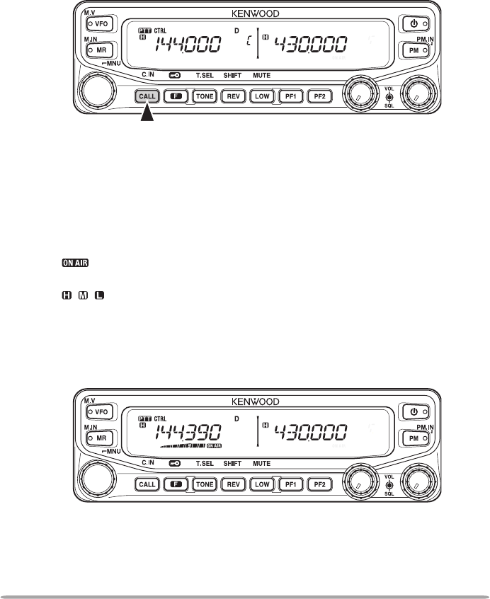
r CALL
Press [CALL] to select the Call channel. Press [CALL] (1s) to start Call scan
{page 48}. Press [F], [CALL] to store the current operating frequency to the
Call channel {page 33}.
t F
Press [F] to enter Function mode. Press [F] (1s) to turn the transceiver key
lock function ON or OFF {page 63}.
y TONE
Press [TONE] to turn the Tone function ON. Continually press [TONE] to
toggle the functions as follows: Tone ON >> CTCSS ON >> DCS ON >> OFF.
While Tone, CTCSS, or DCS is ON, press [F], [TONE] to enter CTCSS or
DCS setup mode.

9
u REV
Press [REV] to turn the Reverse function ON or OFF {page 30}. Press [REV]
(1s) to turn the Automatic Simplex Checker ON {page 30}. Press [F], [REV]
to enter Offset Direction selection mode. Each time you press [F], [REV], the
offset direction toggles as follows:
plus (+) direction –> minus (–) direction –> –7.6 MHz (E type only) –> OFF.
i LOW
Press [LOW] to toggle the transmit output power as follows: High Power (K,
E types only) –> Middle Power –> Low Power {page 70}. Press [F], [LOW] to
turn the Mute function ON or OFF {page 69},
o PF1
Press [PF1] to activate its programmable function {page 66}. The default
function is “Frequency Band Select”.
!0 PF2
Press [PF2] to activate its programmable function {page 66}. The default
function is “Operation Band Select”.
!1 BAND SEL (VOL) Control
Rotate the [BAND SEL] control to adjust the speaker volume {page 14}.
Press the left [BAND SEL] to select the A band. Press the right [BAND SEL]
to select the B band. Press [BAND SEL] (1s) to toggle between single and
dual-band mode.
!2 SQL Control
Rotate the [SQL] control to adjust the squelch level. Clockwise opens the
squelch and counterclockwise tightens the squelch {page 68}.
!3 PM
Press [PM] to enters the PM (Programmable Memory) channel selection mode
{page 40}. Press [F], [PM] to enter PM Channel registration mode {page 40}.
!4
Press to turn the transceiver power ON and OFF.
10
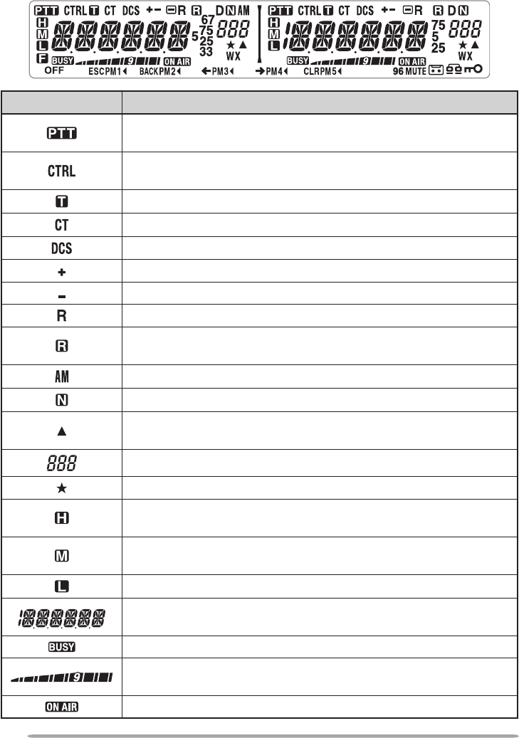
DIsPlAy
Indicator Description
Appears when there is a transmission band available. Blinks
when the cross-band repeater is ON (K type only).
Appears when there is an operation band available. Blinks
when the wireless remote control is ON (K type only).
Appears when the Tone function is ON.
Appears when the CTCSS function is ON.
Appears when the DCS function is ON.
Appears when the Shift function is set to plus.
Appears when the Shift function is set to minus.
Appears when the Reverse function is ON.
Appears when the ASC function is ON. Blinks when the ASC
function is performing an OK check.
Appears while in AM mode.
Appears while in Narrow FM mode.
Appears when the selected channel is registered while in
Memory Input mode.
Displays the Memory channel and Menu number.
Appears when the Memory Channel Lockout function is ON.
Appears while using High output power. Blinks when the
temperature protection circuit turns on.
Appears while using Middle output power. Blinks when the
temperature protection circuit turns on.
Appears while using Low output power.
Displays the operating frequency, Memory channel name, and
Menu.
Appears when receiving a busy signal.
Performs as an S meter when receiving a signal and displays
the selected power level while transmitting.
Appears while transmitting.
< A Band > < B Band >
11
Indicator Description
Appears while using the data band.
Appears when the data terminal is set as 9600 (bps).
Appears when the frequency is set to ***,***,250 Hz.
Appears when the frequency is set to ***,***,500 Hz.
Appears when the frequency is set to ***,***,750 Hz.
Appears when the frequency is set to ***,***,333 Hz.
Appears when the frequency is set to ***,***,666 Hz.
Appears when the F key is pressed.
Appears when mute has been turned ON.
Appears while making a recording.
Appears when using an EchoLink Memory channel.
Appears when the Key Lock function is ON.
Appears when making a PM call.
Appears while in Menu mode and when the Tone/CTCSS/DCS
code is selected.
Blinks when recalling a PM channel and while writing to memory.
Only the “1” will blink while recording or in playback mode.
Appears while accessing the Menu.
Blinks when recalling a PM channel and while writing to memory.
Only the “2” will blink while recording or in playback mode.
Appears when entering characters in Menu mode or entering a
code.
Blinks when recalling a PM channel and while writing to memory.
Only the “3” will blink while recording or in playback mode
Appears when entering characters in Menu mode or entering a
code.
Blinks when recalling a PM channel and while writing to
memory. Only the “4” will blink while recording or in playback
mode.
Appears when entering characters in Menu mode or entering a
code.
Blinks when recalling a PM channel and while writing to
memory.
Appears when Weather Alert is ON. Blinks when receiving a
signal (K type only).
12
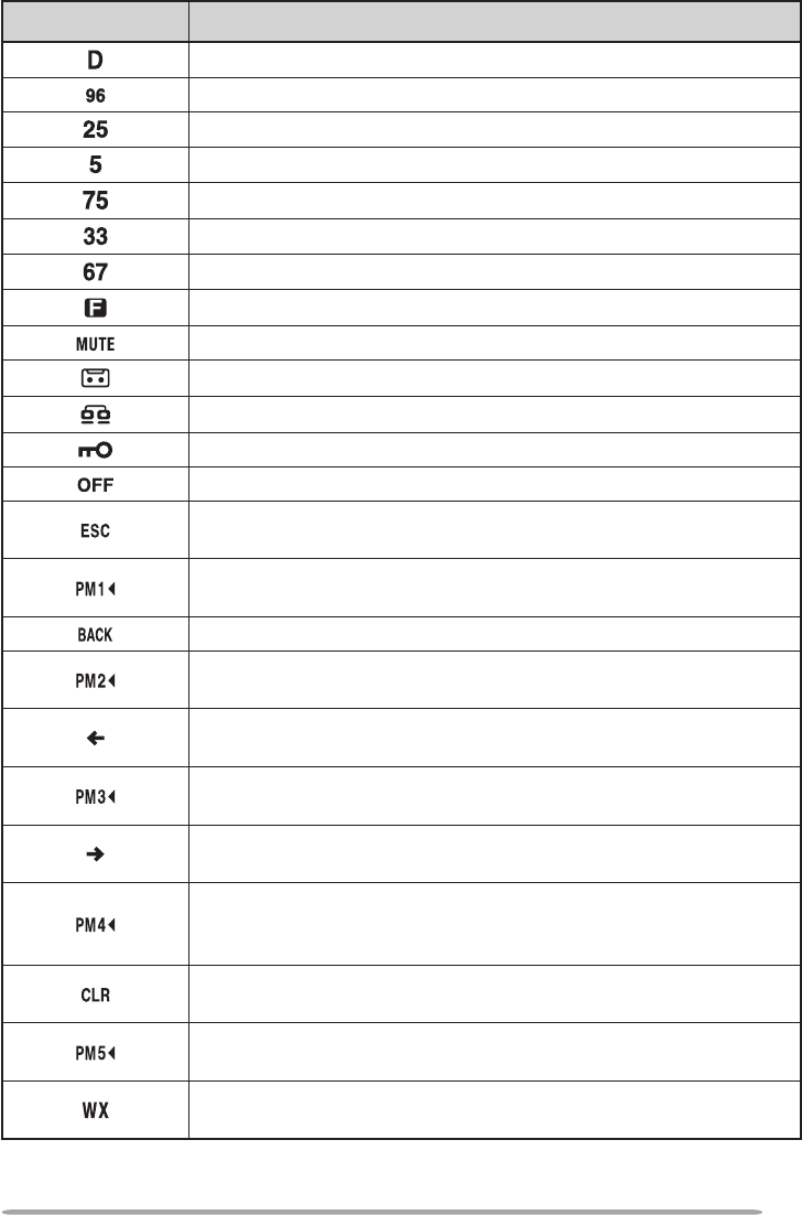
rEAr PANEl
q ANT
Connect an M-type (TM-V71A) or N-type (TM-V71E) external antenna to this
terminal {page 5}. When making test transmissions, connect a dummy load in
place of the antenna. The antenna system or load should have an impedance
of 50 Ω.
w DATA
Connect a TNC unit to this terminal, via a 6-pin mini DIN connector.
e PC
Connect a personal computer to this terminal, via an 8-pin mini DIN connector.
r SP (SP 1/ SP 2)
If desired, connect 1 or 2 external speakers for clearer audio. These jacks
accept 3.5 mm (1/8") diameter, 2-conductor plugs {page 7}. Refer to page 71
to determine how the speakers will be used.
sUb-PANEl
q MIC
Connect the supplied microphone to this jack {page 7}.
w Panel Terminal
When using an optional panel kit, attach the panel to this terminal using the
cable that comes with the panel kit.
MIC
PANEL
13
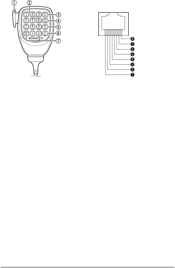
Keypad serial data
No Connection
MIC, 600 Ω impedanc
e
GND (MIC)
PTT
GND
DC 8 V, 100 mA max
No Connection
Microphone (Mc-59)
q PTT switch
Press and hold, then speak into the microphone to transmit.
w DTMF keypad
Press these keys to make DTMF calls, enter frequencies, or enter characters.
e CALL/ A
Functions the same as the transceiver front panel [CALL] key. This is also the
PF4 key and can be reprogrammed with a programmable function {page 66}.
r VFO/ B
Functions the same as the transceiver front panel [VFO] key. This is also the
PF3 key and can be reprogrammed with a programmable function {page 66}.
t MR/ C
Functions the same as the transceiver front panel [MR] key. This is also the
PF2 key and can be reprogrammed with a programmable function {page 66}.
y PF/ D
Press to toggle between bands A and B. This is also the PF1 key and can be
reprogrammed with a programmable function {page 66}.
u UP/ DWN
Functions the same as the transceiver Tuning control.
Microphone Jack
14
BASIC OPERATIONS
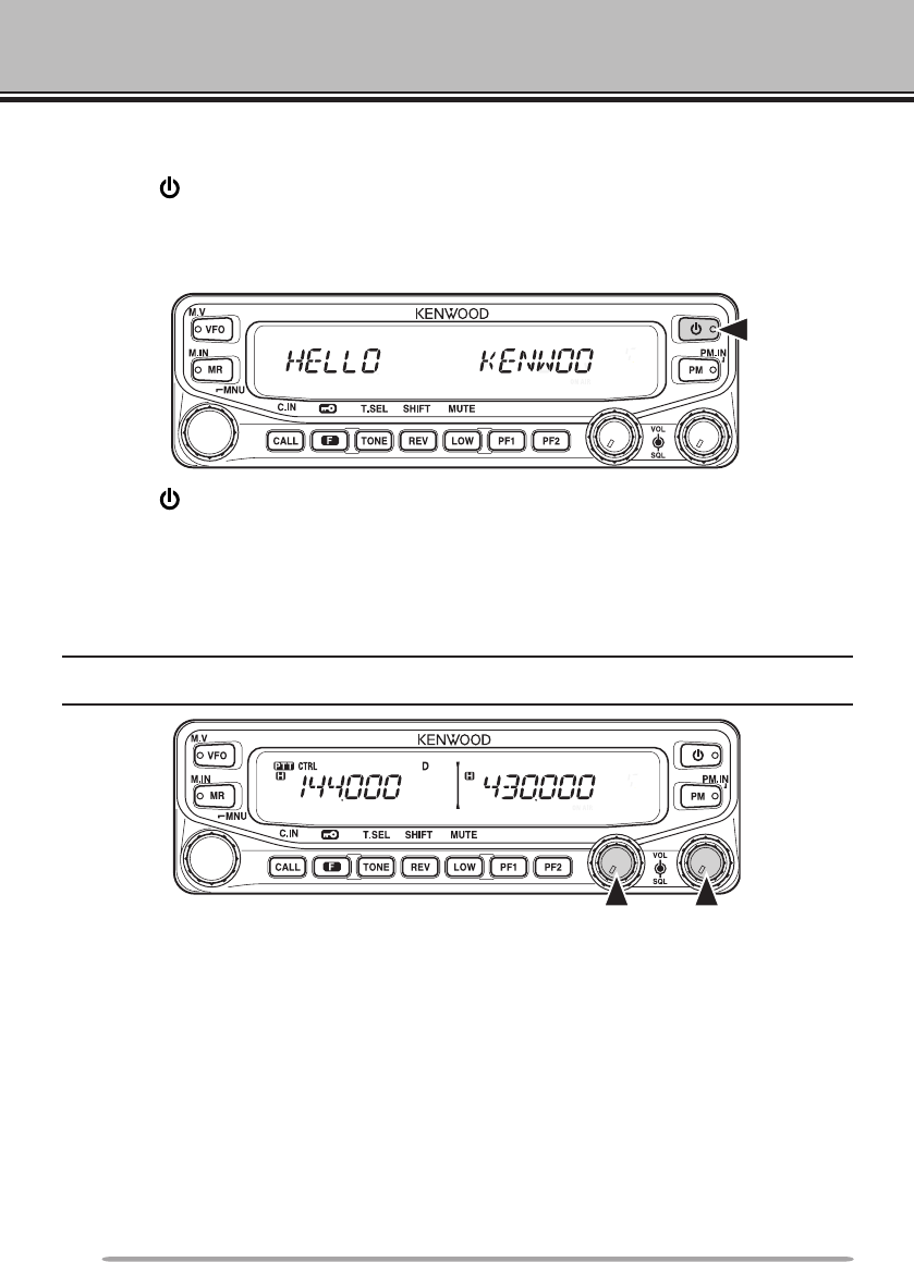
SWITCHING THE POWER ON/ OFF
Press the switch to switch the transceiver ON.
• The power on message momentarily appears on the display.
• Ifthetransceiverpasswordprotectionhasbeenactivated{page74},youmustrstenter
your password before you can operate the transceiver.
Press the switch again to switch the transceiver OFF.
ADJUSTING THE VOLUME
Rotate the [BAND SEL] (VOL) control of your selected band clockwise to
increase the volume and counterclockwise to decrease the volume.
Note: Some functions of this transceiver, such as the beep and voice announcements, have their
own volume settings. Adjust those settings to your desired values.
15
ADJUSTING THE SQUELCH
Squelch is used to mute the speaker when no signals are present. With the
squelch level set correctly, you will hear sound only while actually receiving a
signal. The higher the squelch level selected, the stronger the signals must be in
order to hear them.
Rotate the [SQL] control of your selected band, when no signals are present, and
select the squelch level at which the background noise is just eliminated.
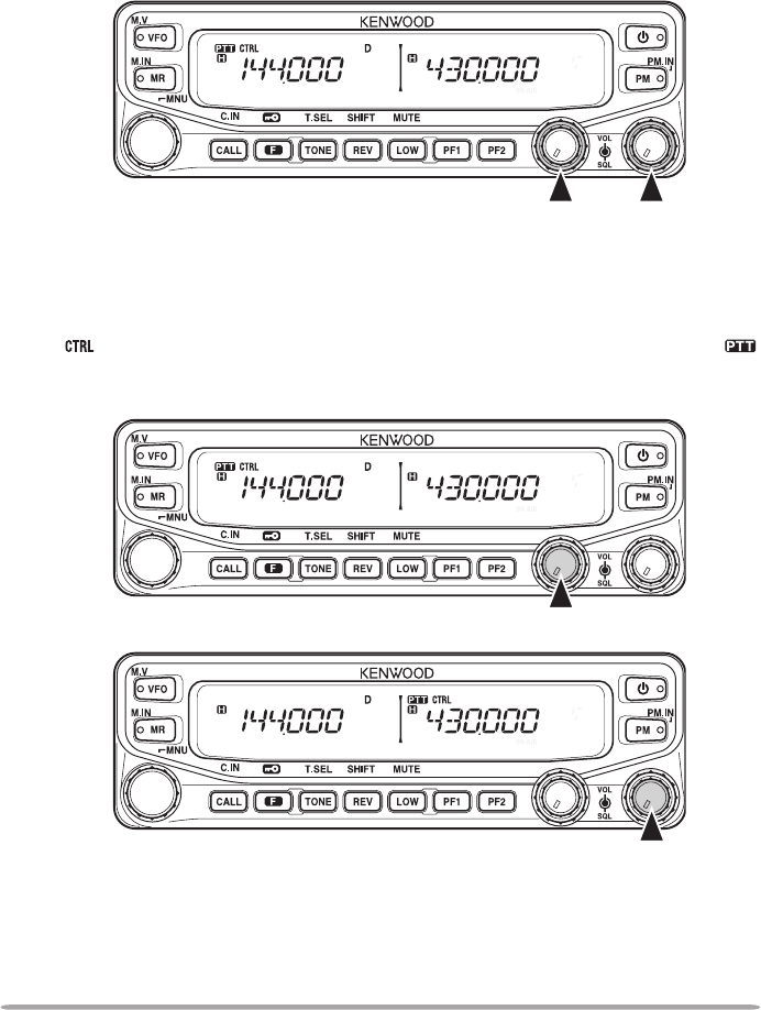
SELECTING A BAND
Press the left [BAND SEL] control to select band A and the right [BAND SEL]
control to select band B.
• The icon appears at the top of the band on which you are operating and the icon
appears at the top of the band on which you are currently set to transmit.
Band A (left [BAND SEL] control):
Band B (right [BAND SEL] control):
16
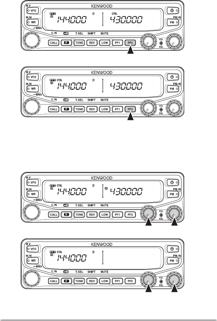
Pressing [PF2] allows you to switch the operating band between bands A and B,
while maintaining the original band as the transmit band.
Band A is the transmit band and band B is the operating band:
Band A is both the transmit and operating band:
SELECTING DUAL BAND MODE/ SINGLE BAND MODE
You can switch the transceiver between dual band operation and single band
operation by pressing [BAND SEL] (1s) of your selected band.
Dual band mode:
Single band mode (band A only):
(In Single band mode, you can turn the center partion bar display off {page 72}.)
17
SELECTING A FREQUENCY BAND
You can change the default frequency bands for bands A and B.
1 Select band A or B by pressing the [BAND SEL] control or [PF2].
2 Press [F], [BAND SEL] of your selected band.
• Each time you press [F], [BAND SEL], you cycle to the next frequency band.
• The default setting of the [PF1] key also allows you to cycle to the next frequency
band.
• When masking a band {page 71}, you are restricted to using only the selectable
band.
• When receiving 2 signals on the same band, the image interference, senstivity, etc.,
performance will decrease.
• Band A: 118 >> 144 (default) >> 220 >> 300 >> 430/440 (MHz).
• Band B: 144 >> 220 >> 430/440 (default) >> 12000 (MHz).
Note:
u M4 type models do not have the following frequency bands available:
118, 220, 300, or 12000 (MHz).
u E and M4 type models use the 430 MHz band and K type models use the 440 MHz band.
SELECTING AN OPERATING MODE
There are 3 operating modes available to choose from: VFO mode, Memory
Channel mode, and Call Channel mode.
■ VFO Mode
VFO mode allows you to manually change the operating frequency.
1 Press [VFO] to enter VFO mode.
18
2 Rotate the Tuning control to select your desired operating frequency.
• You can also adjust the frequency by using the microphone [UP]/[DWN] keys.
• The default step frequency for the Tuning control varies according to the type
and operating band:
Type 144 MHz 430/440 MHz
K 5 kHz 25 kHz
E 12.5 kHz 25 kHz
M4 10 kHz 10 kHz
• To adjust the frequency by a larger amount, you can press the Tuning control
to enter MHz mode. While in MHz mode, rotate the Tuning control to adjust the
frequency in steps of 1 MHz. Press the Tuning control again to exit MHz mode
and adjust the frequency using the normal step frequency.
■ Memory Channel Mode
Memory Channel mode allows you to quickly select a frequently used
frequency and related data which you have saved in the transceiver memory.
1 Press [MR] to enter Memory Channel mode.
2 Rotate the Tuning control to select your desired Memory channel.
19
■ Call Channel Mode
Call Channel mode allows you to quickly select a preset channel to allow
immediate calls on that frequency. The Call channel can be conveniently used
as an emergency channel within your group.
1 Select your desired band (A or B).
• The Call channel has a dedicated frequency for both bands A and B. The
default frequency for band A is 144 MHz. The default frequency for band B is
430/440 MHz.
2 Press [CALL] to enter Call Channel mode.
• The C icon appears on the display.
3 Press [CALL] again to return to your previous operating frequency.
TRANSMITTING
1 Select your desired band and frequency/channel.
2 Press and hold the microphone [PTT] switch and speak into the microphone to
transmit.
• The icon and the RF power meter appear on the display for the selected
transmit band. The RF power meter shows the relative transmit output power.
• The / / icon(s) appear on the display, depending on what output power you
have selected {page 70}.
• Speak into the microphone in your normal voice, while keeping the microphone
approximately 5 cm from your mouth. Speaking too close to the microphone or too
loudly may increase distortion and reduce intelligibility of your signal at the receiving
station.
3 Whenyounishspeaking,releasethe[PTT] switch.
20
MENU MODE
Many functions on this transceiver are selected or congured through the Menu
instead of physical controls. Once you become familiar with the Menu system,
you will appreciate the versatility it offers.
MENU ACCESS
1 Press [F], Tuning control to access the Menu.
• The Menu name and number appears on the display.
2 Rotate the Tuning control to select your desired Menu.
3 Press the Tuning control to set up the current Menu.
4 Rotate the Tuning control to select your desired value for the selected Menu.
5 Press the Tuning control to set the selected value.
6 Repeat steps 2 to 5 to set up additional Menus.
• Press [CALL] (ESC) at any time to exit Menu mode.
• Press [F] (BACK) at any time to cancel the Menu setup and return to the Menu
selection.
MENU CONFIGURATION
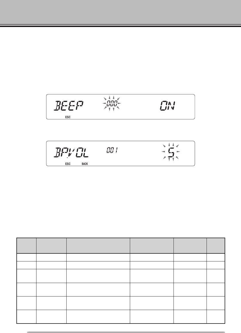
Menu
No. Display Description Setting Values Default
Setting
Ref.
Page
000 BEEP Beep sound OFF/ ON ON 64
001 BP.VOL Beep volume level 1 ~ 7 5 64
002 EXT.SP External speaker output
mode
MODE 1/
MODE 2 MODE 1 71
003 1 ANN Voice announcement
mode
OFF/ AUTO/
MANUAL AUTO 75
004 1 ANN.LNG Voice announcement
language ENG/ JPN ENG 77
005 1 ANN.VOL Voice announcement
volume 1 ~ 7 5 77

21
Menu
No. Display Description Setting Values Default
Setting
Ref.
Page
006 1 ANN.SPD Voice announcement
speed 0 ~ 4 1 77
007 1 PLAY.BK Recording playback
repeat OFF/ ON OFF 80
008 1 P.BK.INT Playback repeat interval
time 0 ~ 60 (seconds) 10 80
009 1 CON.REC Conversation recording OFF/ ON OFF 79
100 PRG.VFO Programmable VFO
setup
Varies with
the selected
frequency band
– 64
101 STEP Step frequency
Varies with
the selected
frequency band
– 65
102 MODLAT Modulation/demodulation
mode
Varies with
the selected
frequency band
– 69
103 VHF.AIP VHF band AIP OFF/ ON OFF 68
104 UHF.AIP UHF band AIP OFF/ ON OFF 68
105 S.SQL S-meter squelch OFF/ ON OFF 68
106 S.SQ.HNG S-meter squelch hangup
time
OFF/ 125/ 250/
500 (ms) OFF 68
107 MUT.HNG Mute hangup time setup
OFF/ 125/ 250/
500/ 750/ 1000
(ms)
OFF 70
108 B.SHIFT Beat shift OFF/ ON OFF 69
109 TOT Time-out timer 3/ 5/ 10
(minutes) 10 70
110 2 WX.ALT Weather alert OFF/ ON OFF 73
200 3 M.NAME Memory name setup Up to 6
characters – 35
201 RECALL Memory channel recall
method ALL/ CURRENT ALL 34
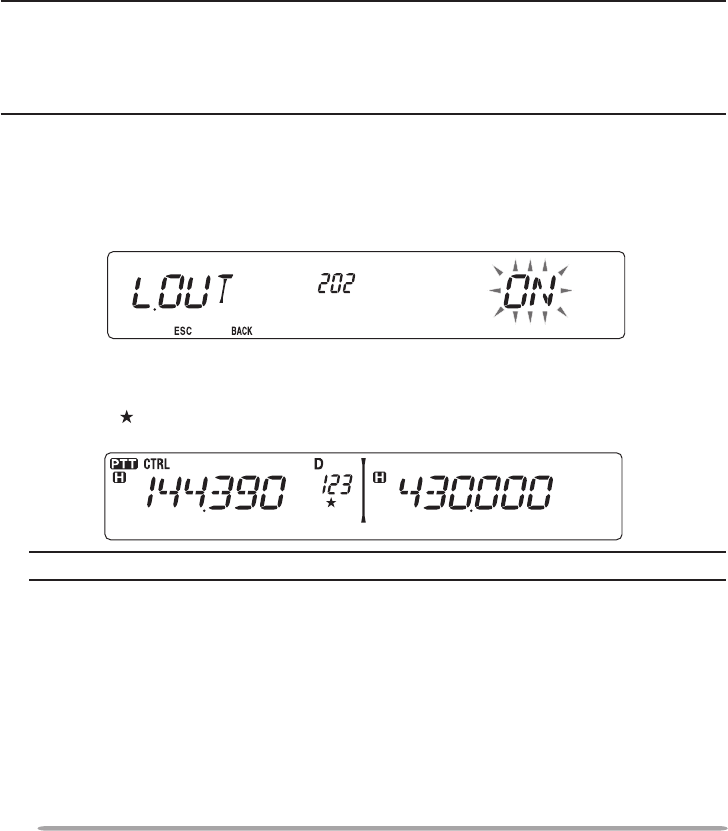
202 3 L.OUT Memory channel lockout OFF/ ON OFF 44
203 GR.LINK Memory group link
registration
Up to 10 digits
(0 ~ 9) – 45
204 ELK.MEM EchoLink memory setting
Up to 8
characters
for EchoLink
memory
– 59
205 ELK.SPD EchoLink memory
transmission speed FAST/ SLOW FAST 60
300 DT.HOLD DTMF transmission hold OFF/ ON OFF 55

22
Menu
No. Display Description Setting Values Default
Setting
Ref.
Page
301 DT.MEM DTMF memory
Up to 8
characters for
DTMF memory
name
Up to 16
characters for
DTMF code
– 56
302 DT.SPD DTMF memory
transmission speed FAST/ SLOW FAST 57
303 DT.PAUS DTMF pause code time
100/ 250/ 500/
750/ 1000/ 1500/
2000 (ms)
500 58
304 DT.LOCK DTMF key lock OFF/ ON OFF 58
400 OFFSET Offset frequency See reference
page – 27
401 4 ARO Auto Repeater Offset OFF/ ON ON 29
402 1750.HD
Transmission hold when
transmitting a 1750 Hz
tone
OFF/ ON OFF 30
403 2 RPT.MOD Repeater mode CROSS/ A-TX/
B-TX CROSS 81
404 2 RPT.HLD Repeater transmission
hold ON/ OFF OFF 82
405 2 RPT.ID Repeater ID registration Up to 6
characters – 82
406 2 ID.TX Repeater ID transmission OFF/ MORSE/
VOICE OFF 82
500 P.ON.MSG Power on message setup Up to 6
characters HELLO 62
501 BRIGHT Display brightness OFF/ 1 ~ 8 8 62
502 AUTO.BR Display auto brightness OFF/ ON OFF 62
503 COLOR Backlight color AMBER/
GREEN AMBER 63
507 PF1 PF1 key programmable
function value
See reference
page FR.BAND 66
508 PF2 PF2 key programmable
function value
See reference
page CTRL 66
509 MIC.PF1
Microphone PF1 key
programmable function
value
See reference
page A/B 66
510 MIC.PF2
Microphone PF2 key
programmable function
value
See reference
page MR 66

23
Menu
No. Display Description Setting Values Default
Setting
Ref.
Page
511 MIC.PF3
Microphone PF3 key
programmable function
value
See reference
page VFO 66
512 MIC.PF4
Microphone PF4 key
programmable function
value
See reference
page
CALL
(K/ M4 types)
1750
(E types)
66
513 MIC.LCK Microphone key lock OFF/ ON OFF 63
514 SC.RESM Scan resume method TO/ CO/ SEEK TO 43
516 APO Auto Power Off time
OFF/ 30/ 60/
90/ 120/ 180
(minutes)
180 67
517 DAT.BND Data Band mode A/ B/ ATX.BRX/
ARX.BTX A 83
518 DAT.SPD Data communications
speed 1200/ 9600 (bps) 1200 83
519 PC .SPD PC terminal baud rate
speed
9600/ 19200/
38400/ 57600
(bps)
9600 84
520 SQC.SRC SQC output type
OFF/ BUSY/
SQL/ TX/
BUSY.TX/
SQL.TX
BUSY.TX 84
521 AUTO.PM Automatic PM entry OFF/ ON ON 41
522 2 REM.ID Personal Identicaton
Number 000 ~ 999 000 85
523 2 ANS.BK Answer back OFF/ ON ON 85
527 DP.BAR Display partition bar OFF/ ON ON 72
998 PROTEC Password protection OFF/ ON OFF 74
999 RESET Reset VFO/ PART/ PM/
FULL VFO 88
1 Menu numbers 03 ~ 09 are available only when the optional VGS-1 unit is installed in the
transceiver.
2 Menu numbers 110, 403 ~ 406, 522, and 523 are available only for K type models.
3 Menu numbers 200 and 202 are available only if a Memory Channel has been stored in the
transceiver.
4 Menu number 401 is available only for K and E type models.
24
CHARACTER ENTRY
Certain menus require you to enter characters, such as the power on message
and memory names. When character entry is required, a cursor will appear on
the display.
1 Press the Tuning control.
• The cursor will blink.
2 Rotate the Tuning control to select your desired character.
• You can enter characters as described below:
- Power on message, memory name, DTMF memory name, and repeater ID (K
type only): 0 ~ 9, A ~ Z, -, /, @, and space
- EchoLink memory: 0 ~ 9, A ~ Z, and space
- DTMF memory: 0 ~ 9, A ~ F, and space
- Memory group link and wireless remote ID (K type only): 0 ~ 9
3 Press the Tuning control to set the selected character.
• The cursor will move to the next digit.
• You can move the cursor to the left or right by pressing [REV] ( ) or [LOW] ( ).
• You can delete the selected character by pressing [PF1] (CLR).
4 Repeat steps 2 and 3 to enter the remaining characters.
• Press [CALL] (ESC) at any time to exit Menu mode.
• Press [TONE] (BACK) at any time to cancel the Menu setup and return to the Menu
selection.
25
n Microphone Keypad Character Entry
The microphone keys can also be used to enter characters. Refer to the table
below for characters corresponding to microphone keys.
Key Character Display (with each press of the key)
1 Q Z 1
2 A B C 2
3 D E F 3
4 G H I 4
5 J K L 5
6 M N O 6
7 P R S 7
8 T U V 8
9 W X Y 9
0 (space) 0
Not used
# – / @
The microphone [A] ~ [D] keys have special functions assigned to them:
[A]: Functions the same as [PF1] (CLR)
[B]: Functions the same as [REV] ( )
[C]: Functions the same as [LOW] ( )
[D]: Functions the same as the Tuning control

26
OPERATING THROUGH REPEATERS
Repeaters are often installed and maintained by radio clubs, sometimes with the
cooperation of local businesses involved in the communications industry.
Compared to simplex communication, you can usually transmit over much greater
distances by using a repeater. Repeaters are typically located on mountain tops
or other elevated locations. They generally operate at higher ERP (Effective
Radiated Power) than a typical station. This combination of elevation and high
ERP allows communications over considerable distances.
REPEATER ACCESS
Most repeaters use a receive and transmit frequency pair with a standard or
non-standard offset (odd-split). In addition, some repeaters must receive a tone
from the transceiver in order to gain access to the repeater. For details, consult
your local repeater reference.
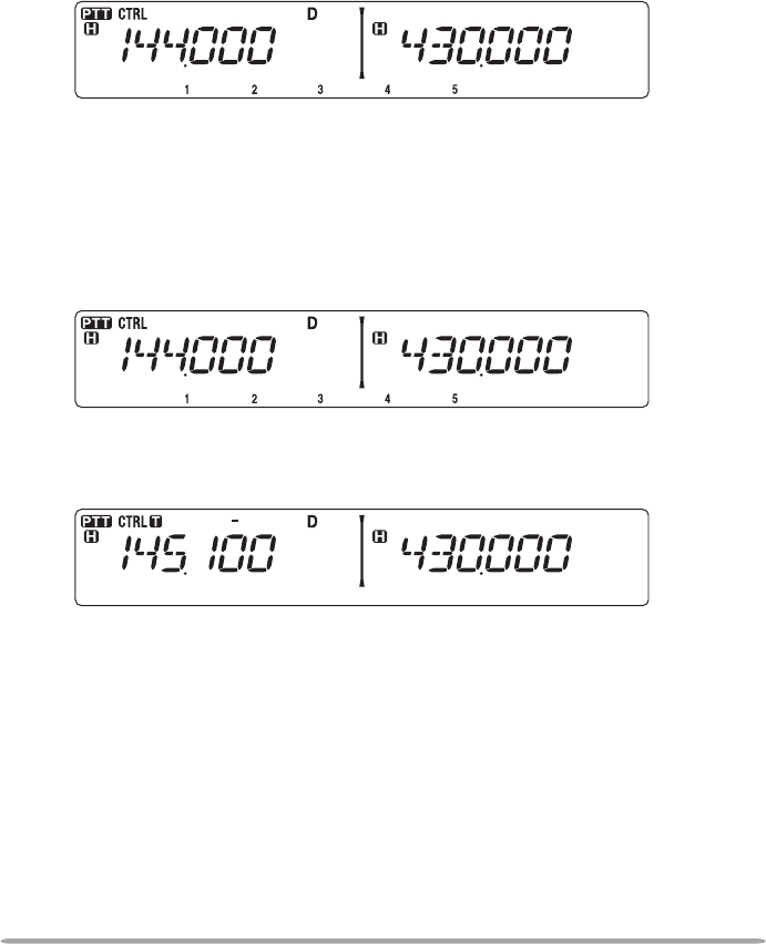
n Selecting an Offset Direction
The offset direction allows your transmit frequency to be higher (+) or lower (–)
than the receive frequency.
1 Select your desired band (A or B).
2 Press [F], [REV] (1s) to select an offset direction.
• Each time you press [F], [REV] (1s), the offset direction changes as follows:
Simplex operation >> + >> – >> Simplex operation
TX: 144.725 MHz
TX tone: 88.5 Hz
RX: 145.325 MHz TX: 144.725 MHz
TX tone: 88.5 Hz
RX: 145.325 MHz
27
• If you are using an E-market transceiver, when operating on the 430 MHz band,
the offset direction changes as follows:
Simplex operation >> + >> – >> = (–7.6 MHz) >> Simplex operation
If the offset transmit frequency falls outside the allowable range, transmitting
is inhibited. Use one of the following methods to bring the transmit frequency
within the band limits:
• Move the receive frequency further inside the band.
• Change the offset direction.
Note: While using an odd-split memory channel or transmitting, you cannot change the offset
direction.
n Selecting an Offset Frequency
The offset frequency is the value which the transmit frequency will be offset
from the receive frequency. The default offset frequency on the 144 MHz band
is 600 kHz for all market versions. The default on the 430/440 MHz band is
5 MHz.
1 Select your desired band (A or B).
2 Enter Menu mode and access Menu 400 (OFFSET) {page 20}.
3 Set the appropriate offset frequency value.
• The selectable range is from 00.00 MHz to 29.95 MHz, in steps of 50 kHz.
Note: After changing the offset frequency, the new offset frequency will also be used by
Automatic Repeater Offset {page 29}.
n Activating the Tone Function
To turn the Tone function on:
1 Select your desired band (A or B).
2 Press [TONE] to turn the Tone function ON.
• Each time you press [TONE], the selection changes as follows:
None >> T (Tone) >> CT (CTCSS) >> DCS (DCS) >> None
Note: When accessing a repeater that requires a 1750 Hz tone, you do not need to activate
the Tone function. Simply press the key assigned to the 1750 Hz tone {page 66} to transmit the
tone.
28
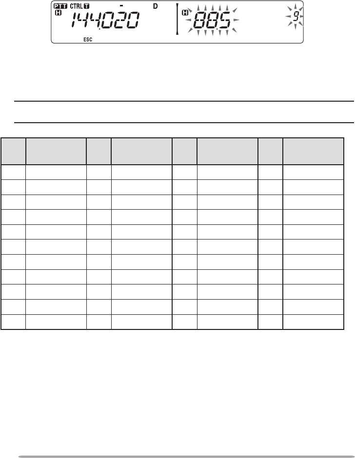
n Selecting a Tone Frequency
To select the tone frequency required to access your desired repeater:
1 Turn the Tone function ON.
2 Press [F], [TONE].
• The current tone frequency appears on the display. The default frequency is
88.5 Hz.
3 Rotate the Tuning control to select your desired frequency.
• To exit the tone frequency selection, press [F] (ESC).
4 Press any key other than the Tuning control and [F] (ESC) to set the
selected frequency.
Note: If you have set up a Memory channel with a tone setting, simply recall the Memory
channel instead of setting up the tone frequency every time.
No. Frequency
(Hz) No. Frequency
(Hz) No. Frequency
(Hz) No. Frequency
(Hz)
01 67.0 12 97.4 23 141.3 34 206.5
02 69.3 13 100.0 24 146.2 35 210.7
03 71.9 14 103.5 25 151.4 36 218.1
04 74.4 15 107.2 26 156.7 37 225.7
05 77.0 16 110.9 27 162.2 38 229.1
06 79.7 17 114.8 28 167.9 39 233.6
07 82.5 18 118.8 29 173.8 40 241.8
08 85.4 19 123.0 30 179.9 41 250.3
09 88.5 20 127.3 31 186.2 42 254.1
10 91.5 21 131.8 32 192.8
11 94.8 22 136.5 33 203.5
29
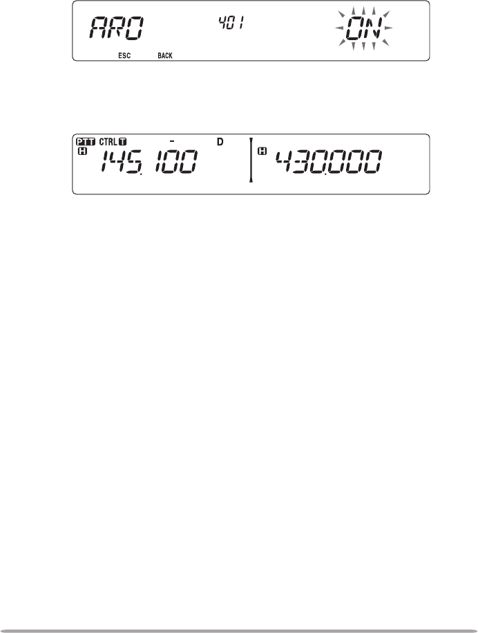
n Automatic Repeater Offset (K and E Types Only)
This function automatically selects an offset direction and activates the Tone
function, according to the frequency that you have selected. To obtain an up-
to-date band plan for repeater offset direction, contact your national Amateur
Radio association.
1 Enter Menu mode and access Menu 401 (ARO) {page 20}.
2 Set the ARO to ON.
3 Press [BAND SEL A] to select the A band.
4 Press [VFO] to select VFO mode.
5 Rotate the Tuning control to select your desired frequency.
6 Press [PTT] to start a call.
• You will be transmitting on an offset frequency value determined from your offset
setting value {page 27} and an offset direction depending on your selected
frequency. Refer to the settings below for offset directions:
K Market:
Under 145.100 MHz: No offset (Simplex operation)
145.100 ~ 145.499 MHz: Minus (–) offset
145.500 ~ 145.599 MHz: No offset (Simplex operation)
146.000 ~ 146.399 MHz: Plus (+) offset
146.400 ~ 146.599 MHz: No offset (Simplex operation)
146.600 ~ 146.999 MHz: Minus (–) offset
147.000 ~ 147.399 MHz: Plus (+) offset
147.400 ~ 147.599 MHz: No offset (Simplex operation)
147.600 ~ 147.999 MHz: Minus (–) offset
148.000 MHz and higher: No offset (Simplex operation)
E Market:
Under 145.000 MHz: No offset (Simplex operation)
145.600 ~ 145.799 MHz: Minus (–) offset
145.800 MHz and higher: No offset (Simplex operation)
30
TRANSMITTING A 1750 Hz TONE
Most repeaters in Europe require that a transceiver transmit a 1750 Hz tone.
By turning the 1750 Hz tone menu item ON, the transceiver will automatically
transmit the 1750 Hz tone for 2 seconds whenever you transmit.
1 Enter Menu mode and access Menu 402 (1750HD) {page 20}.
2 Set the tone to ON or OFF.
• When set to ON, the 1750 Hz tone will transmit. When set to OFF, the tone will not
be transmitted.
REVERSE FUNCTION
After setting a separate receive and transmit frequency, you can exchange these
frequencies using the Reverse function. This allows you to manually check the
strength of signals you receive directly from other stations, while using a repeater.
If the station’s signal is strong, move to a simplex frequency to continue the
contact and free up the repeater.
Press [REV] to turn the Reverse function ON or OFF.
• When the Reverse function is ON, the icon will appear on the display.
Note:
u If the transmit frequency is outside the allowable transmit frequency range when using
Reverse, pressing [PTT] will cause an error tone to sound and transmission will be inhibited.
u If the receive frequency is outside the receive frequency range when using Reverse, an error
tone will sound and Reverse will not operate.
u The ARO (Automatic Repeater Offset) will not function when Reverse is ON.
u You cannot switch Reverse ON or OFF while transmitting.
AUTOMATIC SIMPLEX CHECKER (ASC)
While using a repeater, ASC periodically monitors the strength of signals you
receive directly from the other stations. If the station’s signal is strong enough to
allow direct contact without a repeater, the icon blinks.
Press [REV] (1s) to turn the ASC ON.
31
• When the ASC is ON, the icon will appear on the display.
• While direct contact is possible, without the use of a repeater, the icon will begin
blinking.
• To exit ASC, press [REV].
Note:
u Pressing [PTT] will cause the icon to stop blinking.
u ASC does not function if you are using simplex operation.
u ASC does not function while scanning.
u Activating ASC while using Reverse will switch the Reverse function OFF.
u If you recall a Memory channel or the Call channel, and those channels are set up with the
Reverse function switched ON, the ASC will switch OFF.
u ASC causes received signals to be momentarily intermitted every 3 seconds.
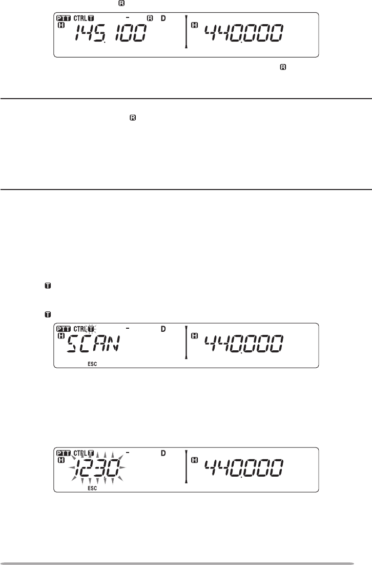
TONE FREQUENCY ID
This function scans through all tone frequencies to identify the incoming tone
frequency on a received signal. You can use this function to nd which tone
frequency is required by your local repeater.
1 Press [TONE] to switch the Tone function ON.
• The icon appears on the display.
2 Press [F], [TONE] (1s) to run the Tone Frequency ID scan.
• The icon blinks and SCAN appears on the display.
• To reverse the scan direction, turn the Tuning control clockwise (upward scan) or
counterclockwise (downward scan).
• To quit the function, press [F] (ESC).
• When the tone frequency is identied, the identied frequency appears on the
display and blinks. Press any key other than the Tuning control while the identied
frequency is blinking, to resume scanning.
3 Press the Tuning control to program the identied frequency in place of the
currently set tone frequency.
• The Tone function will remain ON. You can press [TONE] to switch the Tone
function OFF.
• Press [F] (ESC) if you do not want to program the identied frequency.

32
MEMORY CHANNELS
In Memory channels, you can store frequencies and related data that you often
use. Then you need not reprogram the data every time. You can quickly recall a
programmed channel by simple operation. A total of 1000 Memory channels are
available for bands A and B.
SIMPLEX & REPEATER OR ODD-SPLIT MEMORY CHANNEL?
You can use each memory channel as a simplex & repeater channel or as an odd-
split channel. Store only one frequency to use as a simplex & repeater channel or
two separate frequencies to use as an odd-split channel. Select either application
for each channel depending on the operations you have in mind.
Simplex & repeater channels allow:
• Simplex frequency operation
• Repeater operation with a standard offset (if an offset direction is stored)
Odd-split channels allow:
• Repeater operation with a non-standard offset
The data listed below can be stored in each Memory channel:
Parameter Simplex &
Repeater Odd-split
Receive frequency Yes Yes
Transmit frequency Yes
Receive frequency step size Yes Yes
Transmit frequency step size Yes
Offset direction Yes No
Tone ON/OFF Yes Yes
Tone frequency Yes Yes
CTCSS ON/OFF Yes Yes
CTCSS frequency Yes Yes
DCS ON/OFF Yes Yes
DCS code Yes Yes
Reverse ON/OFF Yes No
Memory channel lockout Yes Yes
Memory channel name Yes Yes
Modulation/Demodulation mode Yes Yes

33
STORINg SIMPLEX AND STANDARD REPEATER FREquENCIES
1 Press [VFO] to enter VFO mode.
2 Rotate the Tuning control to select your desired frequency.
• Additionally, you can press the microphone [UP]/[DWN] keys to select a frequency.
3 Set up any additional data desired for the frequency.
• Offset direction, Tone ON/OFF, Tone frequency, CTCSS ON/OFF, CTCSS frequency,
DCS ON/OFF, DCS code, etc.
4 Press [F].
• A memory channel number appears.
5 Rotate the Tuning control to select your desired channel number.
• Additionally, you can press the microphone [UP]/[DWN] keys to select a channel.
6 Press [MR] to store the data in the selected Memory channel.
Note: If you store the data in a Memory channel that already has data stored in it, the old data will
be cleared and the new data will be stored.
n Call Channel Memory (Simplex)
The Call channel can be used to store any frequency and related data that you
will recall often. You may want to dedicate the Call channel as an emergency
channel within your group.
To store a simplex frequency and related data as the Call channel instead of in
a Memory channel, after step 4 (above), press [CALL].
Note: Storing new data in the Call channel will clear the old data. (The Call channel itself
cannot be cleared, but data can be replaced with new data.)
STORINg ODD-SPLIT REPEATER FREquENCIES
Some repeaters use a receive and transmit frequency pair with a non-standard
offset. To access those repeaters, store two separate frequencies in a memory
channel. You can then operate on those repeaters without changing the offset
frequency you stored in the menu.
1 Set up a simplex channel by following steps 1 to 6 of “STORING SIMPLEX
AND STANDARD REPEATER FREQUENCIES”, above.
2 Press [VFO] to enter VFO mode.
3 Rotate the Tuning control to select your desired transmit frequency.
• Additionally, you can press the microphone [UP]/[DWN] keys to select a frequency.
34
4 Set up any additional data desired for the transmit frequency.
• Tone ON/OFF, Tone frequency, CTCSS ON/OFF, CTCSS frequency, DCS ON/OFF,
DCS code, etc.
5 Press [F].
• A memory channel number appears.
6 Rotate the Tuning control to select your desired channel number.
• Additionally, you can press the microphone [UP]/[DWN] keys to select a channel.
7 Press [PTT], [MR] to store the data in the selected Memory channel.
n Call Channel Memory (Odd-Split)
The Call channel can be used to store any frequency and related data that you
will recall often. You may want to dedicate the Call channel as an emergency
channel within your group.
To store an odd-split frequency and related data as the Call channel instead of
in a Memory channel, after step 6 (above), press [PTT], [CALL].
Note: You cannot store the transmit offset status and Reverse status in an odd-split Call
channel.
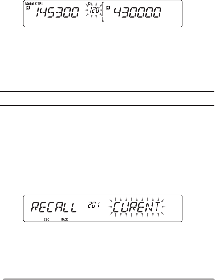
RECALLINg A MEMORY CHANNEL
1 Press [MR] to enter Memory Recall mode.
2 Rotate the Tuning control to select your desired Memory channel.
• Additionally, you can press the microphone [UP]/[DWN] keys to select a channel, or
you can enter a channel number using the microphone keypad.
The transceiver Menu also provides you with the option to recall Memory
channels with storedfrequencies in your current band, or all Memory channels:
1 Enter Menu mode and access Menu 201 (RECALL) {page 20}.
2 Set the recall method to CURENT (current band) or ALL (all bands).
• CURENT allows you to recall only those memory channels that have stored
frequencies within the current band. ALL allows you to recall all programmed
memory channels (such as recalling a 144 MHz frequency channel when operating
in the 430/440 MHz band).
35
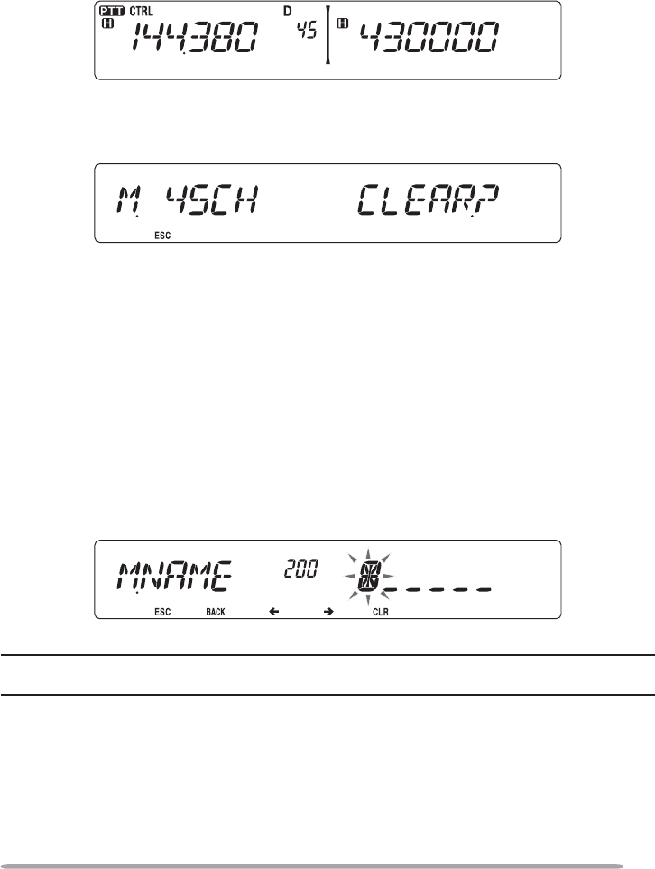
CLEARINg A MEMORY CHANNEL
1 Press [MR] to enter Memory Recall mode.
2 Rotate the Tuning control to select your desired Memory channel.
• Additionally, you can press the microphone [UP]/[DWN] keys to select a channel, or
you can enter a channel number using the microphone keypad.
3 Turn the transceiver power OFF.
4 Press [MR] + Power ON.
• Aconrmationmessageappearsonthedisplay.
5 Press the Tuning control to clear the Memory channel.
• To exit without clearing the channel, press [F] (ESC).
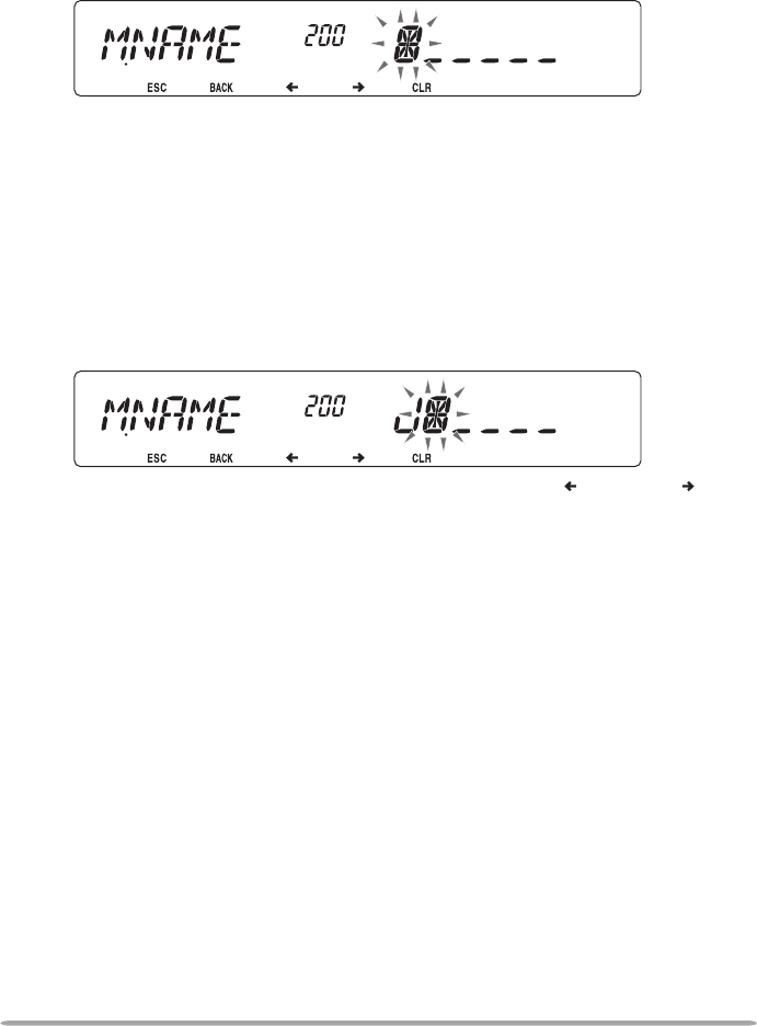
NAMINg A MEMORY CHANNEL
You can name Memory channels using up to 6 alphanumeric characters. When
you recall a named Memory channel, its name appears on the display instead of
the stored frequency. Names can be call signs, repeater names, cities, people,
etc.
1 Press [MR] to enter Memory Recall mode.
2 Rotate the Tuning control to select your desired Memory channel.
3 Enter Menu mode and access Menu 200 (MNAME) {page 20}.
4 Enter your desired name for the channel {page 24}.
Note: You can overwrite a Memory channel name by performing the steps above. You can also
clear a Memory channel name by clearing the Memory channel.
36
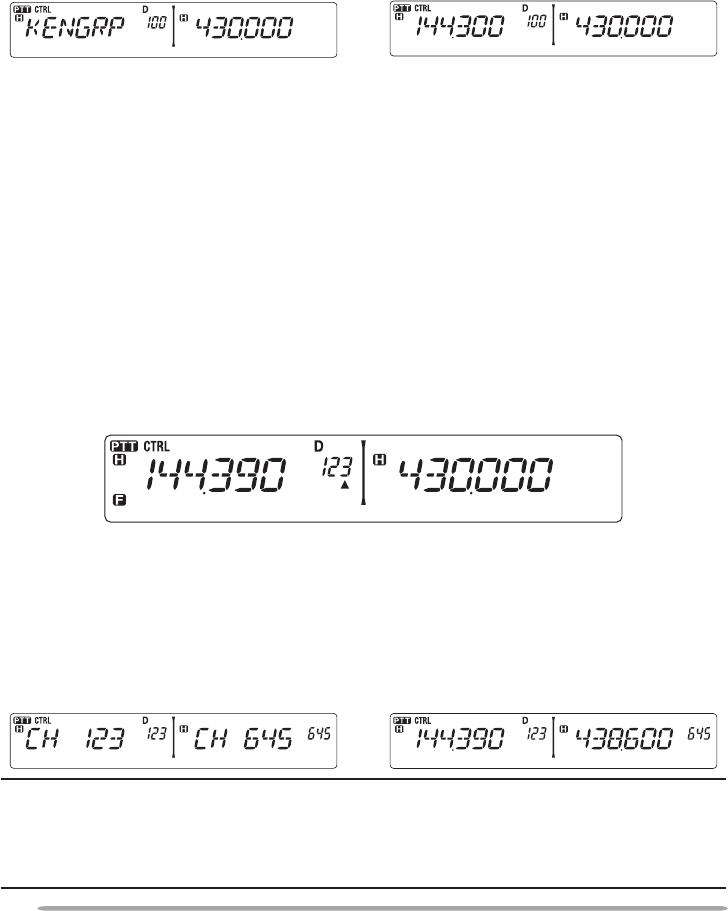
SwITCHINg THE MEMORY NAME/ FREquENCY DISPLAY
After storing memory names, you can switch the display between the memory
nameandthestoredfrequency.Thiscanbeusefulifyouneedtoconrmthe
frequency stored in named Memory channels.
1 Press [MR] to enter Memory Recall mode.
2 Press the Tuning control to toggle between the memory name and the stored
frequency.
<—>
MEMORY-TO-VFO TRANSFER
Transferring the contents of a Memory channel or the Call channel to the VFO
can be useful if you want to search for other stations or a clear frequency, near
the selected Memory channel or Call channel frequency.
1 Press [MR] or [CALL] to enter Memory Recall mode or select the Call
channel.
2 Rotate the Tuning control to select your desired channel. (This step is not
necessary when selecting the Call channel.)
3 Press [F], [VFO].
• The entire contents of the Memory channel or Call channel are copied to the VFO,
and VFO mode is selected after the transfer is complete.
• When copying a transmit frequency from an odd-split Memory or Call channel, you
mustrstturntheReversefunctionONbeforepressing[F], [VFO].
CHANNEL DISPLAY FuNCTION
When this function is switched ON, the transceiver displays only a Memory
channel number instead of a frequency.
1 Turn the transceiver power OFF.
2 Press [LOW] + Power ON to turn the channel display ON or OFF.
<—>
Note:
u If no Memory channels have saved data in them, channel display will not function.
u If a channel has a stored name, the name will appear on the display in place of the channel
number.
u When using Channel Display, you cannot reset the transceiver.

37
While in Channel Display mode, the transceiver keys function as shown below:
Key Name [KEY] [F], [KEY] [KEY] (1s) While
T
ransmitting
[KEY] +
Power ON
Power ON/
OFF
Power ON/
OFF
Power ON/
OFF
Power ON/
OFF
Power ON/
OFF
PM PM Recall PM In – – –
VFO VFO mode Memory to
VFO copy VFO Scan – –
MR MR mode
Store in
Memory
channel
Memory
Scan –Memory
Clear
CALL Call mode Store in Call
channel Call Scan – –
FFunction
mode
Exit Function
mode Key Lock – Reset
TONE
Tone/
CTCSS/
DCS
Tone/
CTCSS/DCS
freq./code
selection
– –
Repeater/
Cross/A-TX/
B-TX/OFF
REV Reverse
ON/OFF
Shift ON/
OFF
ASC ON/
OFF – –
LOW Change
output power Mute – Change
output power
Change
channel
display
PF1
E/M4:
Change
frequency
band
K: Select
the Weather
channel
––––
PF2 Change
control band –––
Turn
EchoLink
ON/OFF
Tuning
control
Change
between the
freq. and CH
name
Menu mode MHz Scan/
Group Scan – –
BAND SEL A
A band Change the
freq. band
Change
Single/Dual –Band Mask
A
BAND SEL B
B band Change the
freq. band
Change
Single/Dual –Band Mask
B

38
PROGRAMMABLE MEMORY (PM)
Programmable Memory (PM) stores virtually all settings currently set on
the transceiver. This transceiver provides 5 PM channels to store 5 sets of
transceiver congurations. Later, you can quickly recall any one of these
channels, depending on the operations you have in mind or the operating
environment.
PROGRAMMABLE InfORMAtIOn
The following programmable settings can be stored in each channel:
• Memory name
• Memory channel lockout
• Channel Display mode
• Repeater mode
• Key lock
• Password protection
• Password
• Memory channel/Call channel/Program scan memory
• DTMF memory
• EchoLink memory
• Data communications speed
• 10 MHz mode
• Mic sensitivity
• SQC data output

39
APPLIcAtIOn ExAMPLEs
The following are examples of how you might use Programmable Memory. These
examples may not represent applications useful to you, but you will understand
the exibility of this function.
Situation: You share your transceiver with other members in your family or
club. However, each individual has personal preferences for how they like to set
various functions. You have to keep changing many settings each time you use
the transceiver.
Solution: Because 5 PM channels are available, up to 5 persons can separately
program the transceiver and store their customized environment. Then each
person can quickly change to his or her favorite settings, simply by recalling a
PM channel. It is too much trouble to change back the settings after somebody
else has recongured them. So this application may avoid having a feature-rich
transceiver but never using many useful features.
Situation: While operating mobile on the way to work every morning, you prefer
a silent transceiver that does not interrup the morning calm. In addition, you feel
that a bright display is useless in the sunlight. At night when driving home, you
realize the Beep function truly does serve a purpose and you acknowledge it is
nice to see a bright display after dark.
Solution: In 2 PM channels, store the same operating data such as frequency,
offset, tone, etcl, and store different settings for the Display brightness and Beep
functions. Then you can quickly recall the best settings for day or night operation.
Situation: You cannot gure out how to exit the current transceiver mode.
Solution: Simply recall PM channel 1, which contains an exact copy of the
transceiver default environment. You will not lose the contents of any memory
channels.
40
stORInG DAtA In PM chAnnELs
1 Conrm that the following conditions have been satised:
• The transceiver is in receive mode.
• Scan is not being used.
• Microphone Control is OFF.
2 Congure the transceiver with your desired settings.
• For data that can be stored, refer to page 38.
3 Press [F], [PM].
• PM channel numbers 1 to 5 appear and blink at the bottom of the display.
4 Enter a channel number ([1] to [5]) corresponding to your desired PM channel.
• The settings are stored in the PM channel.
REcALLInG PM chAnnELs
1 Press [PM].
• PM channel numbers 1 to 5 appear on the bottom of the display.
2 Enter a channel number ([1] to [5]) corresponding to your desired PM channel.
• The settings stored in the PM channel are recalled.
• The selected channel number appears on the display.
41
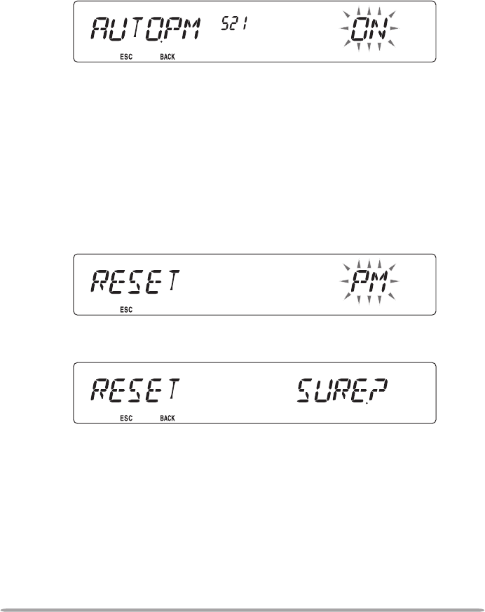
AutO PM chAnnEL stORE
After you recall a PM channel, this function automatically overwrites the current
PM channel with the present operating environment when:
• You recall another PM channel.
• You press [PM].
• You switch the transceiver power OFF.
Follow the steps below to activate the Auto PM storage function.
1 Enter Menu mode and access Menu 521 (AUTOPM) {page 20}.
2 Set AUTOPM to ON.
PM chAnnEL REsEt
To reset the PM channels to their default settings:
1 Turn the transceiver power OFF.
2 Press [F] + Power ON.
3 Release [F].
4 Rotate the Tuning control and select PM.
5 Press the Tuning control.
• A conrmation message appears on the display.
6 Press the Tuning control again to reset the PM channels.
• Press [TONE] (BACK) to return to the previous display.
• To exit without resetting the PM channels, press [F] (ESC).

42
SCAN
Scan is a useful feature for hands-off monitoring of your favorite frequencies.
Becoming comfortable with all types of Scan will increase your operating
efciency.
This transceiver provides the following types of scans:
Scan Type Scan Range
VFO Scan Scans all frequencies on the current band.
Memory Scan Scans all frequencies stored in the Memory channels.
Group Scan Scans the frequencies in the Memory channels which
belong to the group you have specied.
Program Scan Scans all frequencies within the programmed range, on
the current band.
MHz Scan Scans all frequencies within a 1 MHz range from the
originating frequency.
Call Scan Scans the Call channel as well as the currently selected
VFO frequency or Memory channel.
Note:
u Adjust the squelch level before using Scan. Selecting a squelch level too low could cause
Scan to stop immediately.
u While using CTCSS or DCS, Scan stops for any signal received; however, you will hear audio
only when the signal contains the same CTCSS tone or DCS code that you selected.
u When using S-meter Squelch, Scan stops when the received signal strength matches or
exceeds the S-meter setting. Scan resumes 2 seconds after the signal level drops below the
S-meter setting.
u Pressing and holding [PTT] causes Scan to temporarily stop if it is functioning on a non TX
band.
u Starting Scan switches the Automatic Simplex Checker OFF.
43
SELECTING A SCAN RESUME METHOD
The transceiver stops scanning at a frequency or Memory channel on which a
signal is detected. It then continues scanning according to which resume mode
you have selected. You can choose one of the following modes. The default is
Time-operated mode.
• Time-Operated mode
The transceiver remains on a busy frequency or Memory channel for
approximately 5 seconds, and then continues to scan even if the signal is still
present.
• Carrier-Operated mode
The transceiver remains on a busy frequency or Memory channel until the
signal drops out. There is a 2 second delay between signal drop-out and scan
resumption.
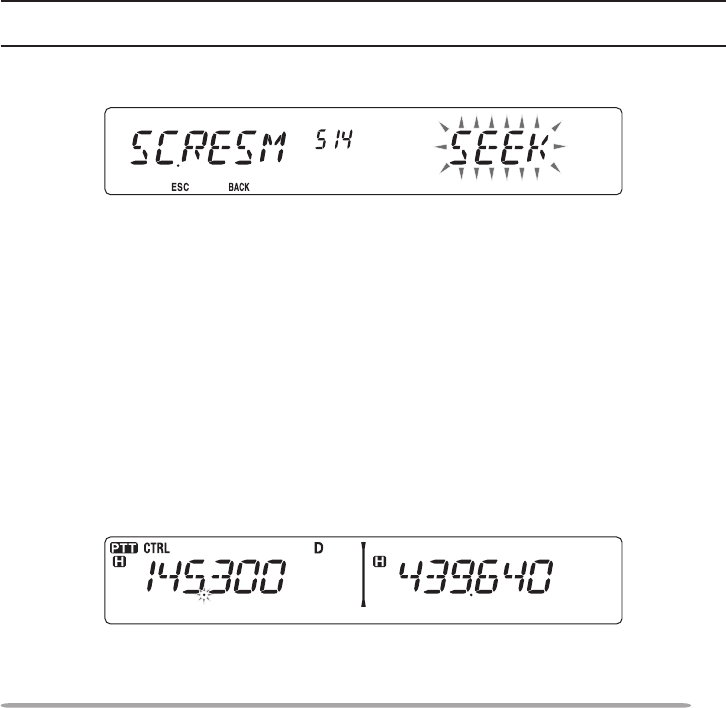
• Seek mode
The transceiver remains on a busy frequency or Memory channel even after
the signal drops out and does not automatically resume scanning.
Note: To temporarily stop scanning and monitor weak signals, press the microphone PF key
assigned to the Monitor function {page 66}. Press the PF key again to resume scanning.
1 Enter Menu mode and access Menu 514 (SC.RESM) {page 20}.
2 Set the Scan Resume mode to TO (Time-Operated), CO (Carrier-Operated) or
SEEK.
VFO SCAN
VFO Scan monitors all frequencies tunable on the band, using the current
frequency step size.
1 Select your desired band.
2 Press [VFO] (1s).
• Scan starts at the current frequency.
• The 1 MHz decimal blinks while scanning is in progress.
• To reverse the scan direction, turn the Tuning control clockwise (upward scan) or
counterclockwise (downward scan). You can also press microphone [UP]/ [DWN].
3 To quit VFO Scan, press [VFO] again.
44
MEMORY SCAN
Use Memory Scan to monitor all Memory channels programmed with frequency
data.
1 Select your desired band.
2 Press [MR] (1s).
• Scan starts at the current frequency.
• The 1 MHz decimal blinks while scanning is in progress.
• To reverse the scan direction, turn the Tuning control clockwise (upward scan) or
counterclockwise (downward scan). You can also press microphone [UP]/ [DWN].
3 To quit Memory Scan, press [MR] again.
Note:
u At least 2 Memory channels must contain data and must not be locked out of scan.
u The L0/U0 to L9/U9 Memory channels will not be scanned.
u You can also start Memory Scan when in Channel Display mode. While Scan is paused on a
channel, the channel number blinks.
n Locking Out a Memory Channel
You can select Memory channels that you prefer not to monitor while scanning.
1 Press [MR], then rotate the Tuning control to select your desired channel.
2 Enter Menu mode and access Menu 202 (L.OUT) {page 20}.
3 Set the lockout to ON to lock the channel out of the scanning sequence.
• To cancel lockout, set the lockout to OFF.
• The icon appears on the display for a channel that has been locked
out.
Note: The L0/U0 to L9/U9 Memory channels cannot be locked out.
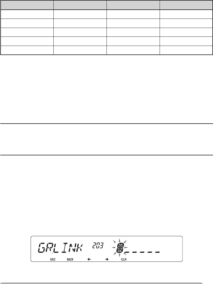
45
GROUP SCAN
For the purpose of Group Scan, the 1000 Memory channels are divided into 10
groups, with each group containing 100 channels. Group Scan monitors only the
100 channels which belong to the specic group you are scanning. The channels
are grouped as follows:
Memory Group Channel Range Memory Group Channel Range
0 0 ~ 99 5 500 ~ 599
1 100 ~ 199 6 600 ~ 699
2 200 ~ 299 7 700 ~ 799
3 300 ~ 399 8 800 ~ 899
4 400 ~ 499 9 900 ~ 999
1 Press [MR], then rotate the Tuning control to select a channel in your desired
group.
2 Press [MHz] (1s).
• Scan starts at the current channel.
• The 1 MHz decimal blinks while scanning is in progress.
• To reverse the scan direction, turn the Tuning control clockwise (upward scan) or
counterclockwise (downward scan). You can also press microphone [UP]/ [DWN].
3 To quit Group Scan, press [MHz] again.
Note:
u At least 2 Memory channels in the selected group must contain data and must not be locked
out of scan.
u You can also start Memory Scan when in Channel Display mode. While Scan is paused on a
channel, the channel number blinks.
n Memory Group Link
Memory Group Link provides you with the ability to link 2 or more Memory
channel groups together to act as a single group when scanning. You can link
up to 6 separate groups together, or even add multiple instances of the same
group to the group link, to ensure that one group is scanned more often than
the other groups.
1 Enter Menu mode and access Menu 203 (GR.LINK) {page 20}.
2 Press the Tuning control.
• The cursor will begin blinking.
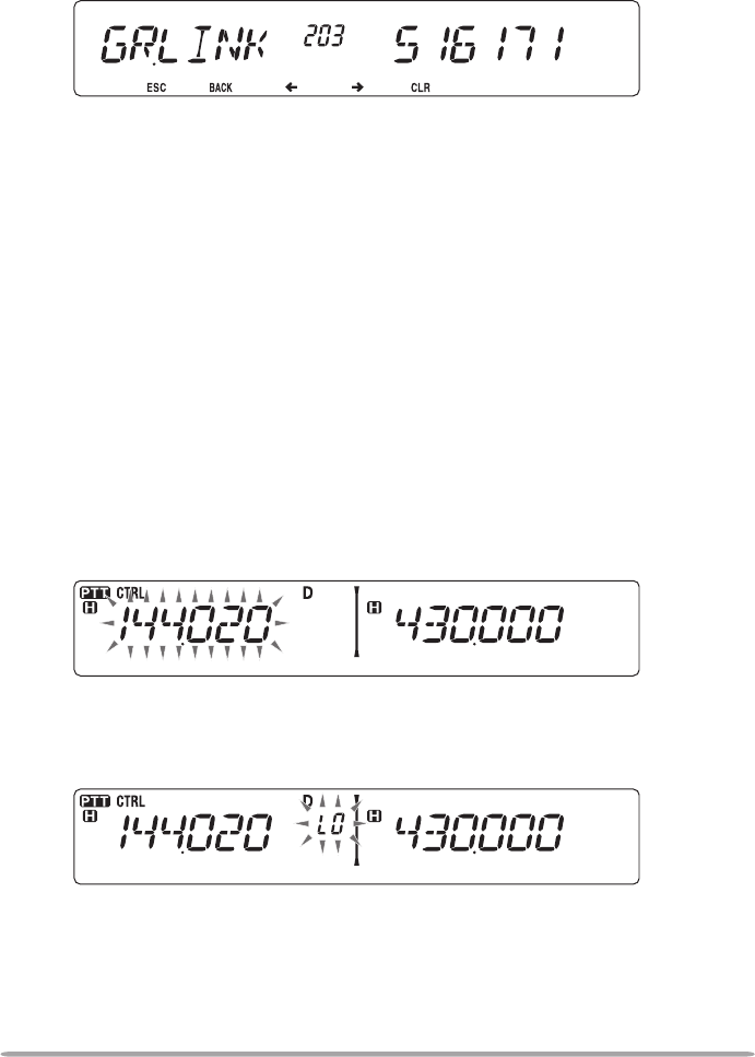
46
3 Rotate the Tuning control to select a group to link.
4 Press the Tuning control to set the group and move the cursor to the right.
• Press [TONE] (<) to move the cursor back or [LOW] (>) to move the cursor to
the right.
5 Repeat steps 3 and 4 to link additional groups together.
6 When you have entered your desired groups, press [LOW] (>) to move the
cursor to the right, then press the Tuning control to complete the entry and
exit Menu mode.
• If you have entered the maximum of 6 groups, simply press the Tuning control to
complete the entry and exit Menu mode.
PROGRAM SCAN
Program Scan is identical to VFO Scan except that you select a frequency range
for the scan.
n Setting Scan Limits
You can store up to 10 scan ranges in Memory channels L0/U0 to L9/U9.
1 Select your desired band.
2 Press [VFO].
3 Rotate the Tuning control to select your desired frequency for the lower
limit.
4 Press [F].
• A memory channel number appears and blinks.
5 Rotate the Tuning control to select a channel from L0 to L9.
6 Press [MR] to set the channel number.
• The lower limit is stored in the channel.
7 Rotate the Tuning control to select your desired frequency for the lower
limit.

47
8 Press [F].
9 Rotate the Tuning control to select a matching channel number from U0 to
U9.
• For example, if you selecte channel L3 in step 5, select channel U3 here.
10 Press [MR] to set the channel number.
• The upper limit is stored in the channel.
• To conrm the stored scan limits, press [MR], then select the L and U
channels.
Note:
u The lower limit must be lower in frequency than the upper limit.
u The lower and upper frequency step sizes must be equal.
u The lower and upper limits must be selected on the same band.
n Using Program Scan
1 Select your desired band.
2 Press [VFO].
3 Rotate the Tuning control to select a frequency within your desired scan
range.
4 Press [VFO], (1s).
• Scan starts at the current frequency.
• The 1 MHz decimal blinks while scanning is in progress.
• To reverse the scan direction, turn the Tuning control clockwise (upward scan)
or counterclockwise (downward scan). You can also press microphone [UP]/
[DWN].
5 To quit Program Scan, press [VFO] again.
Note:
u If the step size differs between the lower limit and upper limit, VFO scan will begin instead
of Program Scan.
u If the current VFO frequency is within more than one Program Scan range, the range
stored in the smallest channel number is used.

48
MHz SCAN
MHz Scan monitors a 1 MHz segment of the band, using the current frequency
step size. The current 1 MHz digit determines the limits of the scan. For
example, if the current frequency is 145.400 MHz, then the scan range would be
from 145.000 MHz to 145.995 MHz (the exact upper limit depends on the current
frequency step size).
1 Select your desired band.
2 Press [VFO].
3 Rotate the Tuning control to select a frequency within your desired 1 MHz
range.
4 Press and hold the Tuning control for 1 second to start scanning.
• Scan starts at the current frequency.
• The 1 MHz decimal blinks while scanning is in progress.
• To reverse the scan direction, turn the Tuning control clockwise (upward scan) or
counterclockwise (downward scan). You can also press microphone [UP]/ [DWN].
5 To quit MHz Scan, press the Tuning control again.
CALL SCAN
Use Call Scan to monitor both the Call channel and either the currently selected
VFO frequency or the currently selected Memory channel.
1 Select your desired VFO frequency or Memory channel.
2 Press [CALL] (1s) to start Call Scan.
• The 1 MHz decimal blinks while scanning is in progress.
• When scanning a Memory channel, the Call channel on the same band as the
selected Memory channel is used for scan.
3 To quit Call Scan, press [CALL] again.
Note: The Memory channel selected is scanned even if it has been locked out of scan.