JVCKENWOOD 408000 144MHz FM Transceiver Model : TH-255A User Manual
JVC KENWOOD Corporation 144MHz FM Transceiver Model : TH-255A
User Manual

INSTRUCTION MANUAL
© B62-1981-00 (K, M)
09 08 07 06 05 04 03 02 01 00
144 MHz FM TRANSCEIVER
TH-255A

Thank You
We are grateful you decided to purchase this Kenwood FM
transceiver. Kenwood always provides Amateur Radio products
which surprise and excite serious hobbyists. This transceiver is no
exception. Kenwood believes that this product will satisfy your
requirements for both voice and data communications.
FeaTures
• Compact design
• Aluminum die-cast chassis
• High output power (up to 5 W operation)
• 100 memory channels or 50 channels with names
• Long operation period with a Ni-MH battery pack (optional)
WriTing ConvenTions FolloWed in This Manual
The writing conventions described below have been followed to
simplify instructions and avoid unnecessary repetition.
Instruction Action
Press [KEY]. Momentarily press [KEY].
Press [KEY] (1s). Press and hold KEY for 1 second or longer.
Press [F], [KEY].
Press the [F] key to enter Function mode,
then press [KEY] to access its secondary
function.
Press [KEY] + Power
ON.
With the transceiver power OFF, press and
hold [KEY] while turning the transceiver
power ON.

i
Notices to the User
◆ Government law prohibits the operation of unlicensed radio
transmitters within the territories under government control.
◆ Illegal operation is punishable by fine and/or imprisonment.
◆ Refer service to qualified technicians only.
Safety: It is important that the operator is aware of, and
understands, hazards common to the operation of any
transceiver.
PrecaUtioNs
• Do not charge the transceiver and battery pack when they are wet.
• Ensure that there are no metallic items located between the
transceiver and the battery pack.
• Do not use options not specified by kenwood.
• If the die-cast chassis or other transceiver part is damaged, do not
touch the damaged parts.
• If a headset or headphone is connected to the transceiver, reduce
the transceiver volume. Pay attention to the volume level when
turning the squelch off.
• Do not place the microphone cable around your neck while near
machinery that may catch the cable.
• Do not place the transceiver on unstable surfaces.
• Ensure that the end of the antenna does not touch your eyes.
• When the transceiver is used for transmission for many hours, the
radiator and chassis will become hot. Do not touch these locations
when replacing the battery pack.
• Do not immerse the transceiver in water.
• Always switch the transceiver power off before installing optional
accessories.
ii
Turn the transceiver power off in the following locations:
• In explosive atmospheres (inflammable gas, dust particles,
metallic powders, grain powders, etc.).
• While taking on fuel or while parked at gasoline service stations.
• Near explosives or blasting sites.
• In aircrafts. (Any use of the transceiver must follow the
instructions and regulations provided by the airline crew.)
• Where restrictions or warnings are posted regarding the use of
radio devices, including but not limited to medical facilities.
• Near persons using pacemakers.
• Do not disassemble or modify the transceiver for any reason.
• Do not place the transceiver on or near airbag equipment while
the vehicle is running. When the airbag inflates, the transceiver
may be ejected and strike the driver or passengers.
• Do not transmit while touching the antenna terminal or if
any metallic parts are exposed from the antenna covering.
Transmitting at such a time may result in a high-frequency burn.
• If an abnormal odor or smoke is detected coming from the
transceiver, switch the transceiver power off immediately,
remove the battery pack from the transceiver, and contact your
Kenwood dealer.
• Use of the transceiver while you are driving may be against
traffic laws. Please check and observe the vehicle regulations
in your area.
• Do not expose the transceiver to extremely hot or cold
conditions.
• Do not carry the battery pack (or battery case) with metal
objects, as they may short the battery terminals.
• When operating the transceiver in areas where the air is dry, it
is easy to build up an electric charge (static electricity). When
using a earphone accessory in such conditions, it is possible for
the transceiver to send an electric shock through the earphone
and to your ear. We recommend you use only a speaker/
microphone in these conditions, to avoid electric shocks.

iii
One or more of the following statements may be
applicable:
FCC WARNING
This equipment generates or uses radio frequency energy. Changes
or modifications to this equipment may cause harmful interference
unless the modifications are expressly approved in the instruction
manual. The user could lose the authority to operate this equipment
if an unauthorized change or modification is made.
INFORMATION TO THE DIGITAL DEVICE USER REQUIRED BY
THE FCC
This equipment has been tested and found to comply with the limits
for a Class B digital device, pursuant to Part 15 of the FCC Rules.
These limits are designed to provide reasonable protection against
harmful interference in a residential installation.
This equipment generates, uses and can generate radio frequency
energy and, if not installed and used in accordance with the
instructions, may cause harmful interference to radio communications.
However, there is no guarantee that the interference will not occur
in a particular installation. If this equipment does cause harmful
interference to radio or television reception, which can be determined
by turning the equipment off and on, the user is encouraged to try to
correct the interference by one or more of the following measures:
• Reorient or relocate the receiving antenna.
• Increase the separation between the equipment and receiver.
• Connect the equipment to an outlet on a circuit different from that
to which the receiver is connected.
• Consult the dealer for technical assistance.
FCC REGULATIONS REGARDING THE USE OF THE
EMERGENCY CHANNEL
The communications must be for the purpose of soliciting or
rendering assistance to a traveler, or for communicating in an
emergency pertaining to the immediate safety of life or the immediate
protection of property.

iv
CONTENTS
PREPARATION ..............................................................1
Supplied AcceSSorieS ....................................................1
inStAlling the optionAl pB-43n ni-Mh BAttery pAck ...............2
inStAlling AlkAline BAtterieS ...........................................3
inStAlling the AntennA ..................................................4
inStAlling the Belt clip .................................................4
GETTING ACQUAINTED ...................................................5
keyS And controlS ......................................................5
diSplAy ...................................................................8
BASIC OPERATION ....................................................... 10
Switching the power on/oFF ........................................ 10
AdjuSting the VoluMe ................................................. 10
VoluMe AdjuStMent operAtion Selection ............................ 10
AdjuSting the Squelch leVel ......................................... 11
Selecting A Frequency ................................................. 12
direct Frequency entry ............................................... 12
trAnSMitting ........................................................... 13
Selecting An output power ........................................... 14
MENU SETUP .............................................................. 15
whAt iS A Menu?....................................................... 15
Menu AcceSS ........................................................... 15
OPERATING THROUGH REPEATERS .................................. 18
repeAter AcceSS ....................................................... 18
ActiVAting the tone Function ......................................... 20
Selecting A tone Frequency ........................................... 20
tone Frequency id ScAn .............................................. 22
AutoMAtic repeAter oFFSet (k type only) ........................... 23
reVerSe Function ...................................................... 24
AutoMAtic SiMplex checker (ASc) ................................... 24
MEMORY CHANNELS .................................................... 26
nuMBer oF MeMory chAnnelS ......................................... 26
SiMplex & repeAter or odd-Split MeMory chAnnel? .............. 27

v
Storing SiMplex FrequencieS or
StAndArd repeAter FrequencieS .................................... 28
Storing odd-Split repeAter FrequencieS ............................ 28
continuouSly Storing in SiMplex or Split chAnnelS ................ 29
recAlling A MeMory chAnnel ......................................... 30
cleAring A MeMory chAnnel .......................................... 31
nAMing A MeMory chAnnel ............................................ 32
MeMory -to- VFo trAnSFer ........................................... 33
cAll chAnnel .......................................................... 34
recAlling the cAll chAnnel .......................................... 34
reprogrAMMing the cAll chAnnel .................................... 34
chAnnel diSplAy ....................................................... 35
SCAN ....................................................................... 36
Selecting A ScAn reSuMe Method .................................... 37
BAnd ScAn .............................................................. 37
progrAM ScAn ......................................................... 38
MeMory ScAn .......................................................... 39
cAll ScAn .............................................................. 40
priority ScAn .......................................................... 40
MeMory chAnnel lockout ............................................. 42
SELECTIVE CALL ......................................................... 43
continuouS tone coded Squelch SySteM (ctcSS) ................. 43
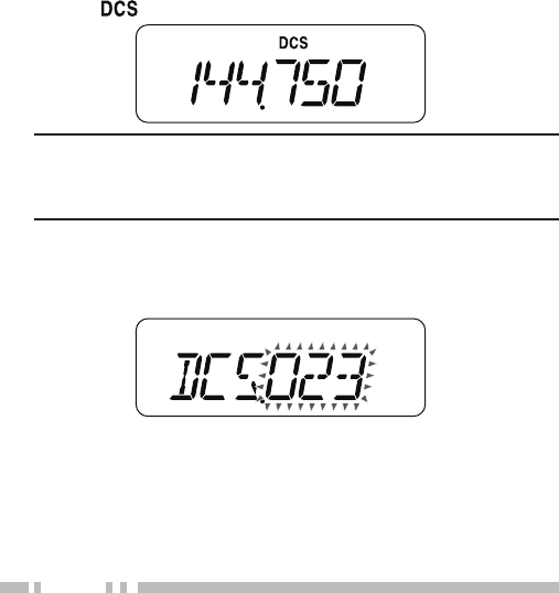
digitAl coded Squelch (dcS) ........................................ 46
DTMF FUNCTIONS ....................................................... 49
MAnuAl diAling ........................................................ 49
dtMF tx hold ........................................................ 50
AutoMAtic diAler ...................................................... 50
AUXILIARY FUNCTIONS ................................................ 54
Apo (Auto power oFF) ............................................... 54
reMAining BAttery cApAcity .......................................... 54
BAttery SAVer ......................................................... 55
BeAt ShiFt .............................................................. 56
Beep Function .......................................................... 57
BuSy chAnnel lockout ................................................ 57

vi
Frequency Step Size ................................................... 58
BAck light ............................................................. 58
lock Function .......................................................... 59
Selector unlock ....................................................... 59
Microphone key lock ................................................. 60
Microphone pF keyS (optionAl) ...................................... 60
Monitor ................................................................ 62
power-on MeSSAge .................................................... 62
progrAMMABle VFo ................................................... 63
tiMe-out tiMer ........................................................ 64
tx inhiBit .............................................................. 64
eMergency Siren ....................................................... 65
MiniMuM/ MAxiMuM VoluMe ........................................... 66
Speaker Attenuation ..................................................... 67
pASSword protection ................................................. 67
OPTIONAL ACCESSORIES .............................................. 69
MAINTENANCE ........................................................... 70
generAl inForMAtion .................................................. 70
SerVice ................................................................. 70
cleAning ................................................................ 71
MicroproceSSor reSet ................................................ 71
operAtion noticeS ..................................................... 73
receiVing SignAlS in citieS ............................................ 73
trAnSMiSSion ........................................................... 73
internAl BeAtS ......................................................... 73
TROUBLESHOOTING ..................................................... 74
SPECIFICATIONS ......................................................... 77
1
PREPARATION
Supplied AcceSSorieS
After carefully unpacking the transceiver, identify the items listed in
the table below. We recommend you keep the box and packings
for the shipping.
Item Part Number Quantity
Antenna T90-1018-XX 1
Belt clip J29-0623-XX 1
Screw set N99-2066-XX 1
Warranty card (K type only) — 1
Instruction manual B62-1981-XX 1
Antenna Belt clip Screw set
2
inStAlling the optionAl pB-43n ni-Mh BAttery pAck
Note: The battery pack is not charged at the factory, you must charge
the battery pack before using it with the transceiver.
1 Unlock (open) the safety catch located at the bottom of the
battery pack.
2 Match the guides of the battery pack with the corresponding
grooves on the upper rear of the transceiver, then firmly press
the battery case to lock it in place.
3 Flip the safety catch into place to prevent accidentally pressing
the release latch and removing the battery pack.
4 To remove the battery pack, lift the safety catch, then press the
release latch to unlock the battery pack. Lift the battery pack
away from the transceiver.
3
inStAlling AlkAline BAtterieS
1 To open the optional BT-14 battery case lid, insert your thumb or
finger into the hole on the top of the battery case, then pull the
cover up.
2 Insert (or remove) six AA (LR6) Alkaline batteries.
• Be sure to match the battery polarities with those marked in
the bottom of the battery case.
3 Align the two tabs at the bottom of battery case, then close the
cover until the locking tabs on top click.
4 To install the battery case onto (or remove it from) the
transceiver, follow steps 1 to 3 of “InstallIng the OptIOnal pB-
43n nI-Mh Battery pack”.
Note:
◆ Do not use Manganese batteries or Ni-Cd batteries in place of
Alkaline batteries.
◆ Always replace all batteries at the same time. Mixing old and new
batteries or mixing types (such as Alkaline with zinc carbon) will
reduce overall performance and could cause leakage or rupture.
◆ Remove all batteries from the case when it is not expected to be in
use for several months.
◆ The voltage of new Alkaline batteries varies slightly, depending on
the manufacturer. Thus, the high battery power indicator may not
appear even though new Alkaline batteries are installed {page 54}.
◆ To lift the battery pack safety catch, use a piece of hardened
plastic or metal, such as a screwdriver, that is no more than 6 mm
wide and 1 mm thick. It is imperative that you place the implement
under only the lip of the safety catch so that you do not damage the
release latch.
4
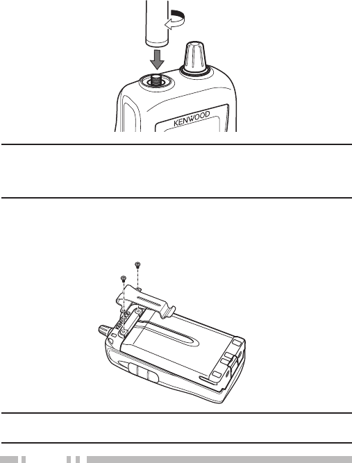
inStAlling the AntennA
Screw the antenna into the connector on the top of the transceiver
by holding the antenna at its base and turning it clockwise until
secure.
Note: The antenna is neither a handle, a key ring retainer, nor a
speaker/ microphone attachment point. Using the antenna in these
ways may damage the antenna and degrade your transceiver’s
performance.
inStAlling the Belt clip
If necessary, attach the belt clip using the two supplied 3 x 4 mm
screws.
Note: If the belt clip is not installed, its mounting location may get hot
during continuous transmission or when left sitting in a hot environment.
5
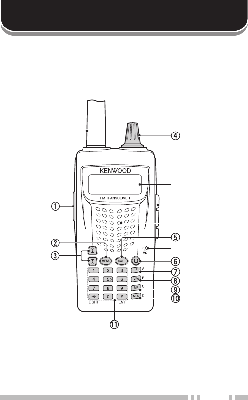
keyS And controlS
GETTING ACQUAINTED
SP/MIC jack cover
Antenna
Speaker
Microphone
Display

6
q [PTT]
Press and hold [PTT] to transmit.
Press [F], [PTT] to toggle the transmit output power between High
and Low {page 14}.
w [MENU]
Press [MEMU] to enter Menu mode {page 15}.
Press [MEMU](1s) to turn the transceiver key lock function ON or
OFF {page 59}
e [UP]( )/ [DOWN]( )
Press [UP]/ [DOWN] to adjust the Volume Level {page 10}.
r Selector
Rotate the Selector to select an operating frequency or Memory
channel, change the scan direction, select a Menu, etc.
t [CALL]
Press [CALL] to select the Call channel {page 34}.
Press [CALL](1s) to start Call scan {page 40}.
Press [F], [CALL] to store the current operating frequency to the
Call channel {page 34}.
y [ ]
Press [ ] (POWER) to turn the transceiver power ON and OFF.
u [F]
Press [F] to enter MHz mode {page 12}.
i [VFO]
Press [VFO] to enter VFO mode {page 12}.
Press [VFO](1s) to start Band scan {page 37}.
Press [F], [VFO] to copy the current Memory channel or Call
channel to the VFO (memory shift) {page 33}.
o [MR]
Press [MR] to enter Memory Channel mode {page 30}.
Press [MR] (1s) to start Memory scan {page 39}.
Press [F], [MR] to store the current operating frequency in the
Memory channel {page 28}.

7
!0 [MON]
Press [MON] to turn the Monitor function ON and OFF {page 62}.
Press [F], [MON] to enter Squelch Level Adjustment mode {page
11}.
!1 Numeric Keypad
[1] Press [F], [1] to select the Signaling (Tone, CTCSS and DCS)
function {pages 20, 44, 46}.
[2] Press [F], [2] to enter the Tone frequency setup mode {page
20}.
Press [F], [2](1s) to start Tone frequency ID scan {page 22}.
[3] Press [F], [3] to change the Frequency step size {page 58}.
[4] Press [F], [4] to enter the DCS code setup mode {page 47}.
Press [F], [4](1s) to start DCS code ID scan {page 48}.
[5] Press [F], [5] to enter the CTCSS frequency setup mode {page
44}.
Press [F], [5](1s) to start CTCSS frequency ID scan {page 45}.
Press [5](1s) to turn the Speaker Attenuation function ON and
OFF {page 66}.
[6] Press [F], [6] to turn the Priority Scan ON or OFF {page 40}.
[7] Press [F], [7] to turn the Reverse function ON or OFF {page 24}.
Press [7](1s) to turn the ASC function ON or OFF {page 24}.
[8] Press [F], [8] to select an Offset direction {page 19}.
[9] Press [F], [9] to turn Memory Channel Lockout ON or OFF {page
42}.
[0] Press [0](1.5s) to turn the Emergency siren ON or OFF {page
65}.
[ ] Press [ ] to illuminate the display and keys {page 58}.
Press [ ](1s) to keep the light ON continuously. {page 58}.
[#] Press [#] to enter the Direct frequency entry mode {page 12}.
Press [F], [#] to enter the Volume Adjustment Operation
Selection mode {page 10}.
8
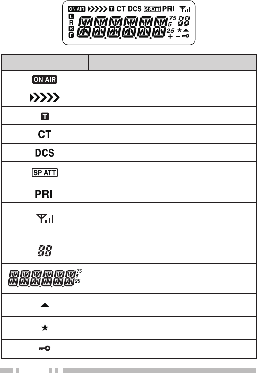
diSplAy
Indicator Description
Appears while transmitting.
Remaining battery capacity indicator (TX).
Appears when the Tone function is ON.
Appears when the CTCSS function is ON.
Appears when the DCS function is ON.
Appears when the Speaker Attenuation
function is ON.
Appears when a Priority Scan function is ON.
Displays the strength of received signals. An
antenna and all 3 strength bars represents
strong signals while the antenna by itself (no
strength bars) represents weak signals.
Displays the Memory channel and Menu
number.
Displays the operating frequency, Memory
channel name, and Menu.
Appears when the selected channel is
registered while in Memory Input mode.
Appears when the Memory Channel Lockout
function is ON.
Appears when the Key Lock function is ON .
9
Indicator Description
Appears when the Offset direction is set to
plus.
Appears when the Offset direction is set to
minus.
Appears while using Low output power.
Appears when the Reverse function is ON.
Appears when the ASC function is ON. Blinks
when the ASC function is performing an OK
check.
Appears when the [F] key is pressed.
10
Switching the power on/oFF
1 Press [ ] (POWER) to switch the transceiver ON.
• The power on message momentarily appears on the display.
• If the transceiver password protection has been activated
{page 67}, you must first enter your password before you can
operate the transceiver.
2 To switch the transceiver OFF, press [ ] (POWER) again.
AdjuSting the VoluMe
Press [UP] to increase the audio output level and press [DOWN] to
decrease the output level.
• If you are not receiving a signal, press and hold [MON] to
unmute the speaker, then adjust the volume control to a
comfortable audio output level.
VoluMe AdjuStMent operAtion Selection
With the setting described below, you can adjust the volume using
either the [UP]/ [DOWN] keys or by operating the Selector.
1 Press [F], [#].
• The selected display appears.
BASIC OPERATION
11
2 Press [F], [#] to toggle the setting between “SEL” and “UP/DN”.
SEL: Adjust the volume using the Selector. To change the
channel number or frequency, use the [UP]/ [DOWN] keys.
UP/DN: Adjust the volume using the [UP]/ [DOWN] keys. To
change the channel number or frequency, use the Selector.
AdjuSting the Squelch leVel
The purpose of Squelch is to mute the speaker when no signals
are present. With the squelch level correctly set, you will hear
sound only while actually receiving signals. The higher the
selected squelch level, the stronger the signals must be to receive.
The appropriate squelch level depends on the ambient RF noise
conditions.
1 Press [F], [MON].
• The current squelch level appears.
2 Rotate the Selector (or press [UP]/ [DOWN]) to adjust the level.
• Select the level at which the background noise is just
eliminated when no signal is present.
• The higher the level, the stronger the signals must be to
receive.
• 6 different levels can be set. 0: Minimum ~ 5: Maximum; 2 is
the default value.
3 Press any key other than [MON] or [ ] to store the new setting
and exit the squelch adjustment.

12
Selecting A Frequency
■ VFO Mode
This is the basic mode for changing the operating frequency.
Rotate the Selector clockwise (or press [UP]) to increase the
frequency and counterclockwise (or press [DOWN]) to decrease
the frequency.
■ MHz Mode
If the desired operating frequency is far away from the current
frequency, it is quicker to use the MHz Tuning Mode.
To adjust the MHz digit:
1 Press [F].
• The MHz digit blinks.
2 Rotate the Selector (or press [UP]/ [DOWN]) to select the
desired MHz value.
3 After selecting the desired MHz value, Press any key other
than [ ] to exit the MHz Tuning Mode and return to normal
VFO Mode.
4 Continue adjusting the frequency as necessary, using the
Selector (or press [UP]/ [DOWN]) keys).
13
direct Frequency entry
In addition to rotating the Selector (or pressing [UP]/ [DOWN]),
there is another way to select the frequency. When the desired
frequency is far away from the current frequency, you can directly
enter a frequency using the numeric keypad.
1 Press [VFO].
• You must be in the VFO Mode to make the direct frequency
entry.
2 Press [#].
3 Press the numeric keys ([0] to [9]) to enter your desired
frequency. [ ] allows you to complete the MHz digits entry.
• Pressing [#] fills all remaining digits (the digits you did not
enter) with 0 and completes the entry. For example, to
select 145.000 MHz, press [1], [4], and [5], then press [#] to
complete the entry.
• If you want to revise the MHz digits only, leaving the kHz
digits as they are, press [VFO] in place of [#].
Note:
◆ If the entered frequency does not match the current frequency
step size, the frequency is automatically rounded down to the next
available frequency.
◆ When the desired frequency cannot be entered exactly, confirm the
frequency step size {page 58}.
◆ If you rotate the Selector (or press [UP]/ [DOWN]) while entering
the frequency, the transceiver clears the entry and changes to the
next available frequency.
14
trAnSMitting
1 To transmit, hold the transceiver approximately 5 cm (2 inches)
from your mouth, then press and hold [PTT] and speak into the
microphone in your normal tone of voice.
• The “ ” icon and the bar-graph meter appears.
• If you press [PTT] while you are outside of the transmission
coverage, a high pitched error beep sounds.
2 When you finish speaking, release [PTT].
Note: If you continuously transmit for longer than the time specified
in Menu No. 12 (default is 10 minutes) {page 64}, the internal timeout
timer generates a warning beep and the transceiver stops transmitting.
In this case, release [PTT] and let the transceiver cool down for a while,
then press [PTT] again to resume transmission.
Selecting An output power
Selecting a lower transmission power is the best way to reduce
battery consumption, if communication is still reliable.
Press [F], [PTT] to toggle between high and low.
• The “ ” icon appears when the lower transmission power.
• The output power varies depending on the battery type and
operating voltage. The table below shows the approximate
output power when the transceiver operates with different types
of battery.
• BT-14 (9.0V) : High - approx. 3.5 W/ Low - approx. 0.3 W
• PB-43N (7.2V) : High - approx. 5.0 W/ Low - approx. 0.5 W
15
MENU SETUP
whAt iS A Menu?
Many functions on this transceiver are selected or configured via a
software-controlled Menu rather than through the physical controls
of the transceiver. Once you become familiar with the Menu system,
you will appreciate its versatility. You can customize the various
timings, settings, and programming functions on this transceiver to
meet your needs without using many controls and switches.
Menu AcceSS
1 Press [MENU].
• A brief explanation of the Menu, and the setting and Menu
No. appear on the display.
2 Rotate the Selector (or press [UP]/ [DOWN]) to select your
desired Menu.
• As you change the Menu No., a brief explanation of each
Menu appears along with its current parameter.
3 Press [MENU] to configure the parameter of the currently
selected Menu No.
Function Parameter
Menu No.
16
4 Rotate the Selector (or press [UP]/ [DOWN]) to select your
desired parameter.
5 Press [MENU] to store the new setting.
Note: Press any key other than [ ], [MON] or [MENU] to cancel the
parameter setting and restore its old value.
Menu Function List
Menu
No. Display Displription Setting Values Default
Setting
Ref.
Page
1 P.VFO Programmable
VFO 136 ~ 173 MHz – 63
2 OFFSET Repeater Offset
Frequency
0.000 ~ 29.950
MHz 0.600 19
3 SCAN Scan resume
method TO/ CO/ SE TO 37
4 M.CH Memory channel
capacity 50/ 100 50 26
5 M.NAME Memory name 6 characters – 32
6 MDF
Memory name/
Frequency
display
MN/ FRQ MN 33
7 SAV Battery saver
OFF/ 0.2/ 0.4/
0.6/ 0.8/ 1.0/ 2.0/
3.0/ 4.0/ 5.0
1.0 55
8 APO Automatic Power-
OFF
OFF/ 30/ 60/ 90/
120/ 180 min. 30 54
9 VOLUME Minimum volume/
Maximum volume 0 ~ 31 Mini:0
Max: 31 66
10 PASSWD Password
protection 6 characters – 67

17
Menu
No. Display Displription Setting Values Default
Setting
Ref.
Page
11 EMG Emergency siren OFF/ VOL/
MED/ MAX OFF 65
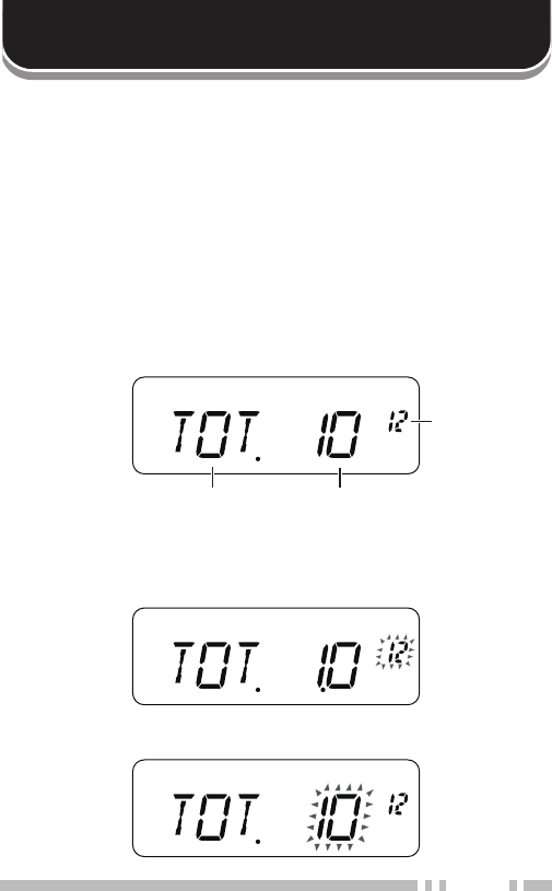
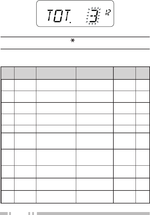
12 TOT Time-out Timer 3/ 5/ 10 min 10 64
13 BCL Busy channel
lockout ON/ OFF OFF 57
14 TXI TX inhibit ON/ OFF OFF 64
15 P.ON.
MSG
Power-ON
message 6 characters – 62
16 BP Beep ON/ OFF ON 57
17 BS Beat Shift ON/ OFF OFF 56
18 SEL Selector unlock ON/ OFF OFF 59
19 DTMF DTMF memory
(Automatic dialer) Up to 16 didits – 50
20 SPD DTMF TX speed FA/ SL FA 52
21 DTH DTMF TX hold ON/ OFF OFF 52
22 PA DTMF pause time
100/ 250/ 500/
750/ 1000/ 1500
/ 2000 ms
500 52
23 DT.L DTMF key Lock ON/ OFF OFF 52
24 M.PF Microphone PF
key ON/ OFF OFF 60
25 ARO
Automatic
Repeater Offset
(K type only)
ON/ OFF ON 23

18
Repeaters are often installed and maintained by radio clubs,
sometimes with the cooperation of local businesses involved in the
communications industry. Compared to simplex communication,
you can usually transmit over much greater distances by using a
repeater. Repeaters are typically located on mountain tops or other
elevated locations. They generally operate at higher ERP (Effective
Radiated Power) than a typical station. This combination of
elevation and high ERP allows communications over considerable
distances.
OPERATING THROUGH REPEATERS
TX: 144.725 MHz
TX tone: 88.5 Hz
RX: 145.325 MHz
TX: 144.725 MHz
TX tone: 88.5 Hz
RX: 145.325 MHz
19
repeAter AcceSS
Most repeaters use a receive and transmit frequency pair with
a standard or non-standard offset (odd-split). In addition, some
repeaters must receive a tone from the transceiver in order to gain
access to the repeater. For details, consult your local repeater
reference.
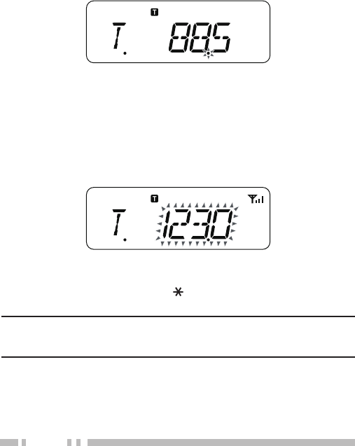
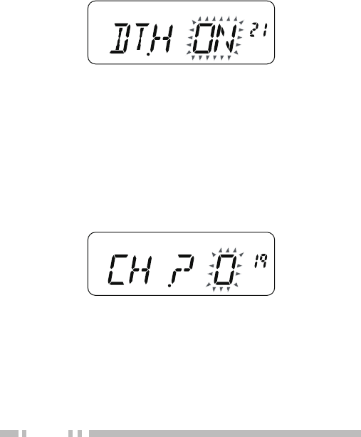
■ Selecting an Offset Direction
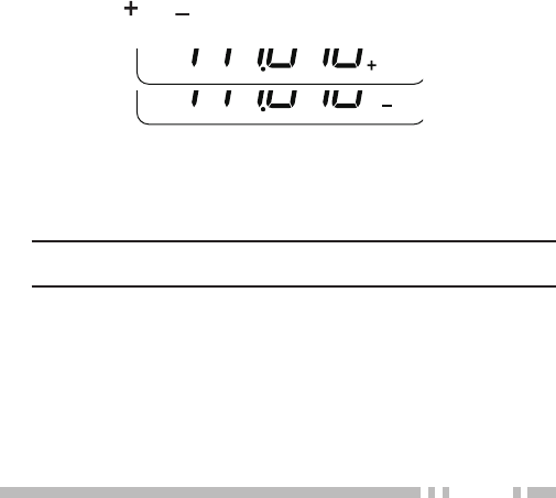
The offset direction allows your transmit frequency to be higher (+)
or lower (–) than the receive frequency.
1 Press [F], [8] to select an offset direction.
• Continually press [F], [8] to toggle the functions as follows:
“+” >> “–” >> OFF.
2 Press any key other than the Selector (or [UP]/ [DOWN]) to
store the setting.
• The “ ” or “ ” icon appears above the frequency,
indicating which offset direction is selected.
If the offset transmission frequency falls outside the allowable
range, transmission is inhibited. In this case, adjust the
reception frequency so that the transmission frequency is
within the band limits.
Note: While using an odd-split memory channel or transmitting,
you cannot change the offset direction.
20
■ Selecting an Offset Frequency
To access a repeater which requires an odd-split frequency pair,
change the offset frequency from the default which is used by
most repeaters.
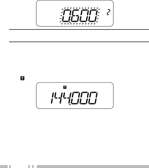
1 Enter Menu mode and access Menu No. 2 (OFFSET).
2 Press [MENU] and rotate the Selector (or press [UP]/
[DOWN]) to select the appropriate offset frequency value.
• The selectable range is from 00.000 MHz to 29.950 MHz,
in steps of 50 kHz.
Note: After changing the offset frequency, the new offset
frequency will also be used by Automatic Repeater Offset.
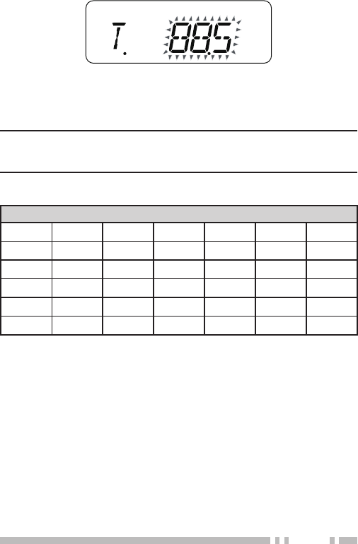
ActiVAting the tone Function
Press [F], [1] to turn the Tone function ON.
• Continually press [F], [1] to toggle the functions as follows: Tone
ON >> CTCSS ON >> DCS ON >> OFF.
• The “ ” icon appears when the Tone function is ON.
Selecting A tone Frequency
To select the tone frequency required to access your desired
repeater:
1 Press [F], [2].
• The current tone frequency appears on the display. The
default frequency is 88.5 Hz.
21
2 Rotate the Selector (or press [UP]/ [DOWN]) to select your
desired frequency.
3 Press any key other than the Selector (or press [UP]/ [DOWN])
to store the setting.
Note: If you have set up a Memory channel with a tone setting, simply
recall the Memory channel instead of setting up the tone frequency
every time.
Available Tone Frequencies
Tone Frequency (Hz)
67.0 82.5 100.0 123.0 151.4 186.2 225.7
69.3 85.4 103.5 127.3 156.7 192.8 229.1
71.9 88.5 107.2 131.8 162.2 203.5 233.6
74.4 91.5 110.9 136.5 167.9 206.5 241.8
77.0 94.8 114.8 141.3 173.8 210.7 250.3
79.7 97.4 118.8 146.2 179.9 218.1 254.1
22
tone Frequency id ScAn
This function scans through all tone frequencies to identify the
incoming tone frequency on a received signal. You can use this
function to find which tone frequency is required by your local
repeater.
1 Press [F], [2](1s) to start the Tone Frequency ID scan.
• When the transceiver receives a signal, scan starts. The
decimal point blinks during scan.
• While the transceiver is receiving a signal during Tone Freq.
ID Scan, the signal is emitted from the speaker.
• To reverse the scan direction, rotate the Selector (or press
[UP]/ [DOWN]).
• When the tone frequency is identified, a beep sounds and the
identified frequency blinks.
2 Press [MENU] to program the identified frequency in place of the
current tone frequency.
• Press any key other than [ ] or [MON] to exit the Scan
function.
Note: Some repeaters do not re-transmit the access tone in the
downlink signal. In this case, check the other station’s uplink signal to
detect the repeater access tone.

23
AutoMAtic repeAter oFFSet (k type only)
This function automatically selects an offset direction, according to
the frequency on the 2 m band. The transceiver is programmed for
offset directions as shown below. To obtain an up-to-date band plan
for repeater offset direction, contact your national Amateur Radio
association.
1 Enter Menu mode and access Menu No. 25 (ARO).
2 Press [MENU] and rotate the Selector (or press [UP]/ [DOWN])
to select “ON”.
3 Press [MENU] to store the setting.
• You will be transmitting on an offset frequency value
determined from your offset setting value {page 19} and an
offset direction depending on your selected frequency. Refer
to the settings below for offset directions:
Under 145.100 MHz: No offset (Simplex operation)
145.100 ~ 145.499 MHz: Minus (–) offset
145.500 ~ 145.599 MHz: No offset (Simplex operation)
146.000 ~ 146.399 MHz: Plus (+) offset
146.400 ~ 146.599 MHz: No offset (Simplex operation)
146.600 ~ 146.999 MHz: Minus (–) offset
147.000 ~ 147.399 MHz: Plus (+) offset
147.400 ~ 147.599 MHz: No offset (Simplex operation)
147.600 ~ 147.999 MHz: Minus (–) offset
148.000 MHz and higher: No offset (Simplex operation)
24
reVerSe Function
After setting a separate receive and transmit frequency, you can
exchange these frequencies using the Reverse function. This allows
you to manually check the strength of signals you receive directly
from other stations, while using a repeater. If the station’s signal
is strong, move to a simplex frequency to continue the contact and
free up the repeater.
Press [F], [7] to turn the Reverse function ON or OFF.
• When the Reverse function is ON, the “ ” icon will appear on the
display.
Note:
◆ If the transmit frequency is outside the allowable transmit frequency
range when using Reverse, pressing [PTT] will cause an error tone
to sound and transmission will be inhibited.
◆ If the receive frequency is outside the receive frequency range
when using Reverse, an error tone will sound and Reverse will not
operate.
◆ The ARO (Automatic Repeater Offset) will not function when
Reverse is ON.
◆ You cannot switch Reverse ON or OFF while transmitting.
AutoMAtic SiMplex checker (ASc)
While using a repeater, ASC periodically monitors the strength of
signals you receive directly from the other stations.
Press [7](1s) to turn the ASC function ON or OFF.
• When the ASC is ON, the “ ” icon will appear on the display.

25
• While direct contact is possible, without the use of a repeater,
the “ ” icon will blink.
Note:
◆ Pressing [PTT] will cause the icon to stop flashing.
◆ ASC does not function if you are using simplex operation.
◆ ASC does not function while scanning.
◆ Activating ASC while using Reverse will switch the Reverse
function OFF.
◆ If you recall a Memory channel or the Call channel, and those
channels are set up with the Reverse function switched ON, the
ASC will switch OFF.
◆ ASC causes received signals to be momentarily intermitted every 3
seconds.
26
MEMORY CHANNELS
In memory channels, you can store frequencies and related data
that you frequently use so that you do not need to reprogram that
data every time. You can quickly recall a programmed channel
through simple operation. A total of 100 memory channels (50
when using the Memory Name function) are available for storing
frequencies, modes and other operating conditions.
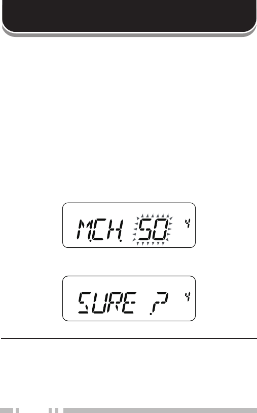
Number of memory ChaNNels
The transceiver must be configured to either 100 memory channels
without using the Memory Name function or 50 memory channels
with the Memory Name function (default).
To change the memory channel capacity:
1 Enter Menu mode and access Menu No. 4 (M.CH).
2 Press [MENU] and rotate the Selector (or press [UP]/ [DOWN])
to select “50” or “100”.
3 Press [MENU].
• “SURE ? ” appears.
4 Press [MENU] to accept.
Note:
◆ If you change the memory channel capacity from 100 channels to 50
channels after having stored data in channels 50 to 99, all memory
channel data in channels 50 to 99 will be erased.
◆ If you change the memory channel capacity from 50 channels to 100
channels after storing Memory names in those channels, all Memory

27
name data will be erased.
simplex & repeater or odd-split memory ChaNNel?
You can use each memory channel as a simplex & repeater
channel or as an odd-split channel. Store only one frequency to use
as a simplex & repeater channel or two separate frequencies to use
as an odd-split channel. Select either application for each channel
depending on the operations you have in mind.
Simplex & repeater channels allow:
• Simplex frequency operation
• Repeater operation with a standard offset (if an offset direction is
stored)
Odd-split channels allow:
• Repeater operation with a non-standard offset.
The data listed below can be stored in each Memory channel:
Parameter Simplex &
Repeater Odd-split
Receive frequency Yes Yes
Transmit frequency Yes
Tone ON Yes Yes
Tone frequency Yes Yes
CTCSS ON Yes Yes
CTCSS frequency Yes Yes
DCS ON Yes Yes
DCS code Yes Yes
Offset direction Yes No
Offset frequency Yes No
Reverse ON Yes Yes
Frequency step size Yes Yes
Beat Shift Yes Yes
Memory channel lockout Yes Yes
Memory channel name Yes Yes

28
storiNg simplex frequeNCies or staNdard repeater
frequeNCies
1 Press [VFO].
2 Rotate the Selector (or press [UP]/ [DOWN]) to select your
desired frequency.
• You can also directly enter a desired frequency using the
keypad.
3 If storing a standard repeater frequency, select the following
data:
• Offset direction
• Tone function, if necessary
• CTCSS/ DCS function, if necessary
If storing a simplex frequency, you may select other related data
(CTCSS or DCS settings, etc.).
4 Press [F], [MR].
• A memory channel number appears and blinks.
• The “ ” icon appears when the channel contains data.
• Memory channel number L0/U0 ~ L2/U2 {page 38} and Pr
(Priority Channel) {page 40} are reserved for other functions.
5 Rotate the Selector (or press [UP]/ [DOWN]) to select the
memory channel in which you want to store the data.
6 Press [MR] to store the data to the channel.
storiNg odd-split repeater frequeNCies
Some repeaters use a pair of reception and transmission
frequencies with a non-standard offset. If you store two separate
frequencies in a memory channel, you can operate on those
repeaters without programming the offset frequency and direction.
1 Store the desired reception frequency and related data by
following the procedure given for simplex or standard repeater
frequencies.
2 Rotate the Selector (or press [UP]/ [DOWN]) to select the
desired transmission frequency.
3 Press [F], [MR].
29
4 Rotate the Selector (or press [UP]/ [DOWN]) to select the
memory channel you programmed in step 1.
5 Press [PTT] + [MR].
• The transmission frequency is stored in the memory channel.
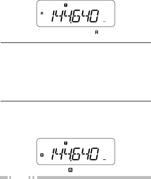
Note: When you recall an odd-split memory channel, “ ” and “ ”
appear on the display. To confirm the transmission frequency, press [F],
[7] (Reverse function).
CoNtiNuously storiNg iN simplex or split ChaNNels
Using the following procedure will be easier to sequentially store
frequencies and related data in more than one simplex or split
memory channel.
1 Press [PTT] + [MON] + Power ON to enter Memory Storage
mode.
2 Press [ ], then rotate the Selector (or press [UP]/ [DOWN]) to
select the desired frequency and select related data as required
(Tone, CTCSS, DTSS, etc.).
• Pressing [ ] toggles frequency select (the MHz dot blinks) or
channel select (the channel number blinks).
3 Press [ ] again, then rotate the Selector (or press [UP]/
[DOWN]) to select the desired memory channel.
4 Press [MR].
• The selected frequency and related data are stored in
the memory channel, and the memory channel number is
incremented.

30
5 Turn the transceiver power OFF, then ON to exit Memory
Storage mode.
To also store a transmit frequency, proceed to step 6; otherwise
proceed to step 10.
6 Press [ ], then rotate the Selector (or press [UP]/ [DOWN]) to
select the desired transmit frequency.
• The frequency selected in step 3 will be used as a receive
frequency.
7 Press [ ], then rotate the Selector (or press [UP]/ [DOWN]) to
select the memory channel that you selected in step 4.
8 Press [F].
9 Press [PTT] + [MR].
• The selected transmit frequency is stored in the memory
channel, and the memory channel number is incremented.
10 Repeat steps 3 to 5 (simplex) or 3 to 9 (split) to sequentially
store in memory channels.
• Turn the transceiver power OFF, then ON to exit Continuous
Memory Storage mode.
Note:
◆ If you use Keypad Direct Entry {page 12} to select a frequency in
step 2, you need not press [ ].
◆ You cannot start Storage mode when in Channel Display mode.
◆ You cannot start Menu mode when in Memory Storage mode.
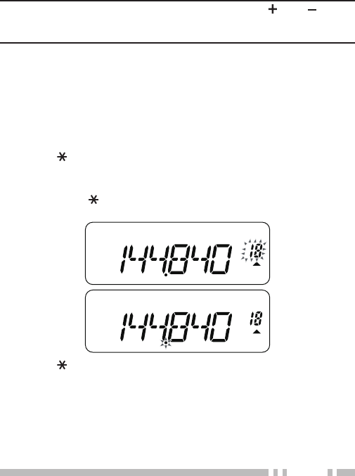
reCalliNg a memory ChaNNel
■ Using the Selector (or [UP]/ [DOWN] keys)
1 Press [MR] to enter Memory Recall Mode. The memory
channel last used is recalled.
2 Rotate the Selector (or press [UP]/ [DOWN]) to select your
desired memory channel.
• You cannot recall an empty memory channel.
• To restore VFO Mode, press [VFO].
31
■ Using a Numeric Keypad
You can also recall a memory channel by entering a desired
memory channel number with the keypad.
1 Press [MR] to enter Memory Recall Mode.
2 Press [#], then enter the channel number using 2 digits.
• For example, to recall channel 49, press [#], [4], [9].
• You can also enter a memory channel number that is less
than 10 by pressing [#] after entering the channel number.
For example, to recall memory channel 9, press [#], [9], [#].
You can also press [#], [0], [9].
Note:
◆ You cannot recall an empty memory channel. An error beep
sounds.
◆ You cannot recall the Program Scan memory channels (L0/U0
~ L2/U2), Priority Channel (Pr) using the numeric keypad.
◆ When you recall an odd-split memory channel, “ ” and “ ”
appear on the display. Press [F], [7] (Reverse function) {page
24} to display the transmission frequency.
◆ After recalling a memory channel, you may modify data such
as Tone or CTCSS. However, these settings are cleared once
you select another channel or the VFO Mode. To permanently
store the data, overwrite the channel contents {page 28}.
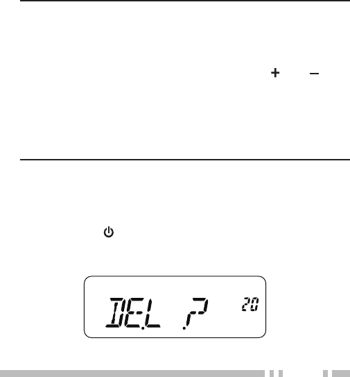
CleariNg a memory ChaNNel
To clear the data from an individual memory channel:
1 Recall the memory channel you want to clear.
2 Press and hold [ ] (POWER) to switch the transceiver OFF.
3 Press [MR] + Power ON .
• A confirmation message appears.
4 Press [MR] to clear the channel data.
32
• The contents of the memory channel are cleared.
• To exit clearing the memory channel, press any key other
than [ ] and [MR].
Note:
◆ Call Channel data cannot be cleared.
◆ You can also clear the Priority Channel, and L0/U0 ~ L2/U2
channels.
◆ While the transceiver is in Channel Display Mode or Lock function
is activated, you cannot clear the channel data.
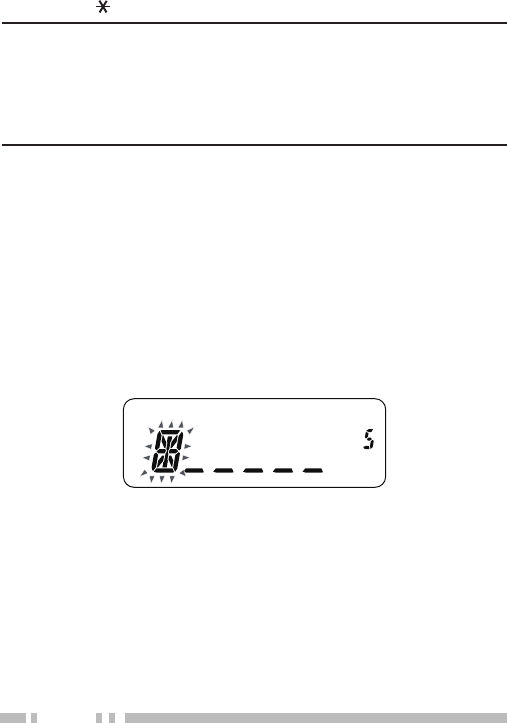
NamiNg a memory ChaNNel
You can name memory channels using up to 6 alphanumeric
characters. When you recall a named memory channel, its name
appears on the display in place of the stored frequency. Names can
be call signs, repeater names, cities, names of people, etc. In order
to use the Memory Name function, the memory channel capacity
must be set to 50 channels. To change the memory channel
capacity from 100 to 50, access Menu No. 4 (M.CH).
1 Enter Menu mode and access Menu No. 5 (M.NAME).
2 Press [MENU].
• A blinking cursor appears.
3 Rotate the Selector (or press [UP]/ [DOWN]) to select a desired
alphanumeric character.
• You can enter the following alphanumeric characters:
0 ~ 9, A ~ Z,-(hyphen), / (slash), and a space.
• Press [CALL] to delete the character at the current cursor
position.
4 Press [MENU].
• The cursor moves to the next digit.
5 Repeat steps 3 and 4 to enter up to 6 digits.

33
• To complete the entry, press [MENU] without selecting a
character.
• After storing a Memory name, the Memory name appears
in place of the operating frequency. However, you can still
display the operating frequency, if desired. To display the
frequency rather than Memory name, access Menu No. 6
(MDF) and select “FRQ”. This menu toggles the display mode
between the Memory name (“MN“) and frequency display
(“FRQ”).
Note:
◆ You cannot name the Call Channel {page 34}.
◆ You cannot assign a Memory name to a channel that does not
contain data.
◆ You can overwrite stored names by repeating steps 1 to 5.
◆ The stored name is erased when you clear the Memory channel
data.
memory -to- Vfo traNsfer
Transferring the contents of a Memory channel or the Call channel
to the VFO can be useful if you want to search for other stations or a
clear frequency, near the selected Memory channel or Call channel
frequency.
1 Press [MR] or [CALL] to enter Memory Recall mode or select
the Call channel.
2 Rotate the Selector (or press [UP]/ [DOWN]) to select your
desired channel. (This step is not necessary when selecting the
Call channel.)
3 Press [F], [VFO].
• The entire contents of the Memory channel or Call channel
are copied to the VFO, and VFO mode is selected after the
transfer is complete.

34
• When copying a transmit frequency from an odd-split Memory
or Call channel, you must first turn the Reverse function ON
before pressing [F], [VFO].
Call ChaNNel
The Call Channel can be recalled instantly no matter what
frequency the transceiver is operating on. For instance, you may
use the Call Channel as an emergency channel within your group.
In this case, Call Scan {page 40} will be useful.
The default Call Channel frequency is 144.000 MHz.
Note: Unlike memory channels 0 to 99, the Call Channel cannot be
cleared.
reCalliNg the Call ChaNNel
Press [CALL] to recall the Call Channel.
• The Call Channel frequency and “C” appear.
• To return to the previous frequency, press [CALL] again.
reprogrammiNg the Call ChaNNel
1 Select your desired frequency and related data (Tone, CTCSS,
DCS, or offset direction, etc.).
• When you program the Call Channel as an odd-split channel,
select a reception frequency first.
2 Press [F], [CALL].
• The selected frequency and related data are stored in the
Call Channel.
To also store a separate transmit frequency, continue with the
following steps.
3 Select the desired transmission frequency.
4 Press [F].
35
5 Press [PTT] + [CALL].
• The separate transmission frequency is stored in the Call
Channel.
Note:
◆ When you recall an odd-split Call Channel, “ ” and “ ” appear on
the display.
◆ Transmit offset status and Reverse status are not stored in an odd-
split Call Channel.
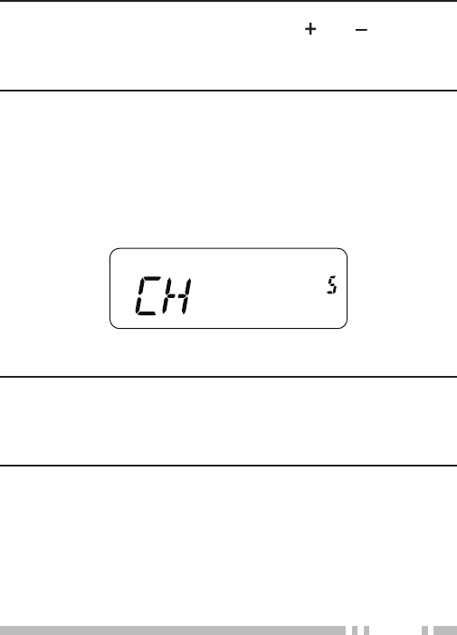
ChaNNel display
While in this mode, the transceiver displays only memory channel
numbers (or Memory names if they have been stored) instead of
frequencies.
Press [PTT] + [MR] + Power ON.
• The transceiver displays the memory channel number in place of
the operating frequencies.
To recover normal operation, turn the transceiver OFF and press
[PTT] + [MR] + Power ON again.
Note:
◆ To enter the Channel Display Mode, you must have at least one
memory channel that contains the data.
◆ If the memory channel contains the Memory name data, the
Memory name is displayed in place of the “CH” characters.

36
SCAN
Scan is a useful feature for hands-off monitoring of your favorite
frequencies.
Becoming comfortable with all types of Scan will increase your
operating efficiency.
This transceiver provides the following types of scans:
◆ Band Scan
Scans all frequencies on the current band.
◆ Program Scan
Scans the specified frequency ranges stored in Memory
channels L0/U0 ~ L2/U2.
◆ Memory Scan
Scans all frequencies stored in the Memory channels.
◆ Call Scan
Scans the Call channel as well as the currently selected VFO
frequency or Memory channel.
◆ Priority Scan
Checks the activities on the Priority channel (Pr) every 3
seconds.
Note:
◆ When the CTCSS or DCS function is activated, the transceiver
stops at a busy frequency and decodes the CTCSS tone or DCS
code. If the tone or code matches, the transceiver unmutes.
Otherwise, it resumes scanning.
◆ Press and hold [MON] to pause scan in order to monitor the
scanning frequency. Release [MON] to resume scanning.
◆ Pressing [MENU] causes scan to stop.
◆ Starting scan switches OFF the Automatic Simplex Check (ASC).
◆ If you press any key other than the following keys during scan,
the transceiver exits scan (excluding Priority Scan). Priority Scan
stops while “PRI” is blinking: [F], [F] (1 s), [MON], Selector, and [F]
then [MON].

37
seleCtiNg a sCaN resume method
The transceiver stops scanning at a frequency or Memory channel
on which a signal is detected. It then continues scanning according
to which resume mode you have selected. You can choose one of
the following modes. The default is Time-operated mode.
◆ Time-Operated mode (TO)
The transceiver remains on a busy frequency or Memory
channel for approximately 5 seconds, and then continues to
scan even if the signal is still present.
◆ Carrier-Operated mode (CO)
The transceiver remains on a busy frequency or Memory
channel until the signal drops out. There is a 2 second delay
between signal drop-out and scan resumption.
◆ Seek mode (SE)
The transceiver remains on a busy frequency or Memory channel
even after the signal drops out and does not automatically
resume scanning.
1 Enter Menu mode and access Menu No. 6 (SCAN).
2 Rotate the Selector (or press [UP]/ [DOWN]) to select a Scan
Resume mode to “TO”, “CO” or “SE”.
baNd sCaN
The transceiver scans the entire band of the frequency you
selected. For example, if you are operating and receiving at 144.525
MHz, it scans all the frequencies available for the 2 m band.
When the current VFO receive frequency is outside the Program
Scan frequency range {page 38}, the transceiver scans the entire
frequency range available for the current VFO.
1 Press [VFO].
2 Turn the Tuning control to select the frequency outside of the
Program Scan frequency range.

38
3 Press [VFO] (1s).
• Scan starts at the current frequency.
• The 1 MHz decimal blinks while scanning is in progress.
• To reverse the scan direction, rotate the Selector clockwise
(or press [UP]) <upward scan> or counterclockwise (or press
[DOWN]) <downward scan>.
4 To exit Band Scan, press [VFO] again.
program sCaN
You can limit the scanning frequency range. There are 3 memory
channel pairs (L0/U0 ~ L2/U2) available for specifying the start and
end frequencies. Program Scan monitors the range between the
start and end frequencies that you have stored in these memory
channels. Before performing Program Scan, store the Program
Scan frequency range to one of the memory channel pairs (L0/U0 ~
L2/U2).
■ Storing a Program Scan Frequency Range
1 Press [VFO].
2 Press [MENU] and rotate the Selector (or press [UP]/
[DOWN]) to select your desired frequency for the lower limit.
3 Press [F], [MR] then rotate the Selector (or press [UP]/
[DOWN]) to select a memory channel from L0 ~ L2.
4 Press [MR] to store the start frequency in the memory
channel.
5 Rotate the Selector (or press [UP]/ [DOWN]) to select your
desired end frequency.
6 Press [F], [MR] then rotate the Selector (or press [UP]/
[DOWN]) to select a channel from U0 ~ U2, corresponding to
the channel selected in step 4.

39
• For example, if you selected L0 in step 4, select U0 for the
end frequency.
7 Press [MR] to store the end frequency in the memory
channel.
■ Using Program Scan
1 Press [VFO].
2 Rotate the Selector (or press [UP]/ [DOWN]) to select a
frequency within the frequency range of memory channel
L0/U0 ~ L2/U2.
3 Press [VFO] (1 s) to start Program Scan.
4 To stop Program Scan, press [VFO] or [PTT].
Note:
◆ If you press [MON], Program Scan temporarily pauses.
Release [MON] to resume scanning.
◆ The transceiver stops scanning when it detects a signal.
◆ If more than 2 Program Scan channel pairs are stored and
overlaps the frequency range among the pairs, the smaller
Program Scan memory channel number has priority.
◆ To perform Program Scan, the “L“ channel must be lower than
the “U“ channel.
memory sCaN
1 Press [MR] (1 s).
• Scan starts from the last memory channel number and
ascends up through the channel numbers (default).
• Rotate the Selector (or press [UP]/ [DOWN]) to change the
scanning direction.
2 To stop Memory Scan, press [MR] or [PTT].

40
Note:
◆ You must have 2 or more memory channels that contain data,
excluding special function memory channels (L0/U0 ~ L2/U2, and
PRI).
◆ You can perform Memory Scan in Channel Display Mode {page
35}.
Call sCaN
1 Select the frequency (in VFO or Memory Recall Mode) you want
to monitor.
• In VFO Mode, rotate the Selector (or press [UP]/ [DOWN])
to select the desired frequency.
• In Memory Recall Mode, rotate the Selector (or press [UP]/
[DOWN]) to select the memory channel you want to monitor.
2 Press [CALL] (1 s) to start the Call Scan.
3 The Call Channel and the selected VFO frequency or memory
channel are monitored.
4 To stop Call Scan, press [CALL] or [PTT].
Note:
◆ The transceiver stops scanning when it detects a signal.
◆ You can perform Call Scan even if the recalled memory channel
has been locked out {page42}.
priority sCaN
You may sometimes want to check your favorite frequency activities
while monitoring other frequencies. In this case, use the Priority
Scan function. Priority Scan checks the activities of the Priority
Channel every 3 seconds. If the transceiver detects a signal on the
Priority Channel, it recalls the frequency.
Note: If you do not operate any control or key for 3 seconds after
the signal drops, the transceiver returns to the original frequency and
resumes Priority Scan.
41
■ Programming Priority Channels
1 Press [VFO].
2 Rotate the Selector (or press [UP]/ [DOWN]) to select your
desired Priority Channel frequency.
3 Select selective call functions, if necessary.
4 Press [F], [MR].
• The memory channel number appears and blinks.
5 Rotate the Selector (or press [UP]/ [DOWN]) to select “Pr”.
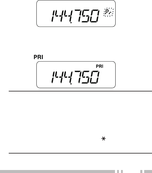
6 Press [MR] to store the data on the Priority Channel.
■ Using Priority Scan
1 Press [F], [6] to turn the Priority Scan ON or OFF.
• The “ ” icon appears when the Priority Scan is ON.
Note:
◆ If a signal is received on a Priority Channel with a CTCSS or
DCS code programmed, the Priority Channel is recalled only
when the programmed tone/ code matches.
◆ Press and hold [MON] to pause Priority Scan when the
transceiver is not displaying the Priority Channel. Release
[MON] to resume Priority Scan.
◆ If you clear the Priority Channels, Priority Scan stops.
◆ You can also press any key other than [ ], [MON], [F] then
[MON] (Squelch lrvel adjustment), [F] then [MENU] (Key lock)
and [PTT] to exit Priority Scan while “PRI” is blinking.

42
memory ChaNNel loCkout
You can lock out memory channels that you prefer not to monitor
during Memory Scan.
1 Press [MR] to enter Memory Recall Mode.
2 Rotate the Selector (or press [UP]/ [DOWN]) to select the
memory channel to be locked out.
3 Press [F], [9] to toggle locked out ON and OFF.
• The “ ” icon appears below the memory channel number,
indicating the channel is locked out.
Note:
◆ The Program Scan memories (L0/U0 ~ L2/U2), Priority Channel (Pr)
cannot be locked out.
◆ Even if a memory channel is locked out, you can perform Call Scan
between the Call Channel and the memory channel.
43
SELECTIVE CAL
CoNtiNuous toNe Coded squelCh system (CtCss)
You may sometimes want to hear calls only from specific persons.
The Continuous Tone Coded Squelch System (CTCSS) allows you
to ignore (not hear) unwanted calls from other persons who are
using the same frequency. To do so, select the same CTCSS tone
as selected by the other persons in your group. A CTCSS tone is
subaudible and is selectable from among 42 tone frequencies.
Note: CTCSS does not cause your conversation to be private. It only
relieves you from listening to unwanted conversations.
■ Using CTCSS
Press [F], [1] 2 times to turn the CTCSS function ON.
• Continually press [F], [1] to cycle through the functions as
follows: Tone ON >> CTCSS ON >> DCS ON >> OFF.
• The “ ” icon appears when the CTCSS function is ON.
Note:
◆ You cannot use the CTCSS and Tone/ DCS functions
simultaneously. Switching the CTCSS function ON after having
activated the Tone/ DCS functions deactivates the Tone/ DCS
functions.
◆ If you select a high CTCSS frequency, receiving audio or noise
that contains the same frequency portions may cause CTCSS
to function incorrectly. To prevent noise from causing this
problem, select an appropriate squelch level}.
44
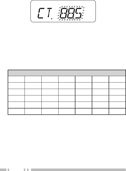
■ Selecting a CTCSS Frequency
1 Press [F], [5].
• The current CTCSS frequency appears on the display.
2 Rotate the Selector (or press [UP]/ [DOWN]) to select your
desired frequency.
3 Press any key other than the Selector (or [UP]/ [DOWN]) to
store the setting.
• The selectable CTCSS frequencies are the same as those
for the Tone frequency. Refer to the table on the following
page for the available CTCSS frequencies.
Available CTCSS Tone Frequencies
Tone Frequency (Hz)
67.0 82.5 100.0 123.0 151.4 186.2 225.7
69.3 85.4 103.5 127.3 156.7 192.8 229.1
71.9 88.5 107.2 131.8 162.2 203.5 233.6
74.4 91.5 110.9 136.5 167.9 206.5 241.8
77.0 94.8 114.8 141.3 173.8 210.7 250.3
79.7 97.4 118.8 146.2 179.9 218.1 254.1
■ CTCSS Frequency ID Scan
This function scans through all CTCSS frequencies to identify
the incoming CTCSS frequency on the received signal. You may
find this useful when you cannot recall the CTCSS frequency
that the other persons in your group are using.
1 Press [F], [5] (1s) to start the CTCSS Frequency ID scan.
• While scanning, the decimal point of CTCSS frequency
blinks.
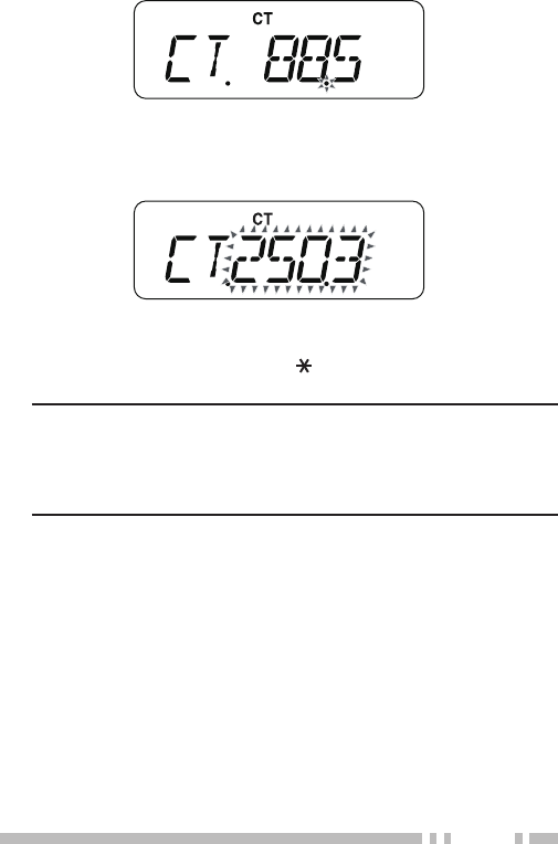
45
• To reverse the scan direction, rotate the Selector (or
press [UP]/ [DOWN]).
• When a CTCSS frequency is identified, the identified
frequency appears and blinks.
2 Press [MENU] to program the identified frequency in place of
the current CTCSS frequency.
• Press any key other than [ ] or [MON] to exit the Scan
function.
Note:
◆ Received signals are monitored through the speaker while
scanning is in progress.
◆ CTCSS Frequency ID Scan does not scan the tone if a signal
is not detected.
46
digital Coded squelCh (dCs)
Digital Code Squelch (DCS) is another application which allows you
to ignore (not hear) unwanted calls. It functions the same way as
CTCSS. The only differences are the encode/ decode method and
the number of selectable codes. For DCS, you can select from 104
different codes.
■ Using DCS
Press [F], [1] 3 times to turn the DCS function ON.
• Continually press [F], [1] to cycle through the functions as
follows: Tone ON >> CTCSS ON >> DCS ON >> OFF.
• The “ ” icon appears when the DCS function is ON.
Note: You cannot use the DCS function and CTCSS/ Tone
functions simultaneously. Switching the DCS function ON after
having activated the CTCSS/ Tone functions deactivates the
CTCSS/ Tone functions.
■ Selecting a DCS Code
1 Press [F], [4].
• The current DCS code appears on the display.
2 Rotate the Selector (or press [UP]/ [DOWN]) to select your
desired code.
3 Press any key other than the Selector (or press [UP]/
[DOWN]) to store the setting.
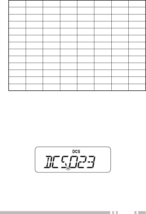
47
Available DCS Code
023 025 026 031 032 036 043 047
051 053 054 065 071 072 073 074
114 115 116 122 125 131 132 134
143 145 152 155 156 162 165 172
174 205 212 223 225 226 243 244
245 246 251 252 255 261 263 265
266 271 274 306 311 315 325 331
332 343 346 351 356 364 365 371
411 412 413 423 431 432 445 446
452 454 455 462 464 465 466 503
506 516 523 526 532 546 565 606
612 624 627 631 632 654 662 664
703 712 723 731 732 734 743 754
■ DCS Code ID Scan
This function scans through all DCS codes to identify the
incoming DCS code on the received signal. You may find this
useful when you cannot recall the DCS code that the other
persons in your group are using.
1 Press [F], [4] (1s) to start the DCS code ID scan.
• While scanning, the decimal point between “DCS” and the
DCS code blinks.
• To reverse the scan direction, rotate the Selector (or
press [UP]/ [DOWN]).
• When a DCS code is identified, the identified DCS code
appears and blinks.

48
2 Press [MENU] to program the identified DCS code in place of
the current DCS code.
• Press any key other than [ ] or [MON] to exit the Scan
function.
Note:
◆ Received signals are monitored through the speaker while
scanning is in progress.
◆ DCS Code ID Scan does not scan the code if a signal is not
detected.
49
DTMF FUNCTIONS
This transceiver provides you with 10 dedicated DTMF memory
channels. You can store a DTMF number (16 digits max.) in each of
these channels to recall later for speed dialing.
Manual Dialing
The numeric keypad functions as a DTMF keypad; the 12 keys
found on a touch-tone phone plus 4 additional keys (A, B, C, D) on
the rightmost column.
To perform Manual Dialing, follow the steps below.
1 Press and hold [PTT] to transmit.
2 While transmitting, press the keys in sequence on the keypad, to
send the DTMF tones.
• The corresponding DTMF tones are transmitted and
monitored through the speaker.
Frequency
(Hz) 1209 1366 1477 1633
697 1 2 3 A
770 4 5 6 B
852 7 8 9 C
941 0 # D
• When DTMF TX Hold is ON, you do not need to continuously
press [PTT] to remain in Transmission Mode. However,
Transmission Mode is retained for only 2 seconds after
pressing a key, so if the next key is not pressed within this
time limit, the transceiver stops transmitting.
50
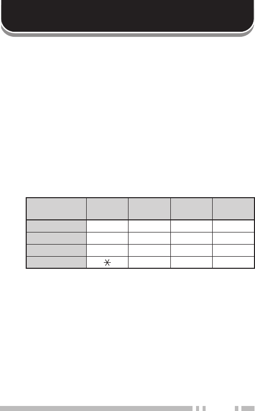
DTMF TX HolD
This function causes the transceiver to remain in Transmission
Mode for 2 seconds after you release each key. So, you can release
[PTT] while sending the DTMF tones.
1 Enter Menu mode and access Menu No. 21 (DTH).
2 Press [MENU] and rotate the Selector (or press [UP]/ [DOWN])
to select “ON”.
3 Press [MENU] to store the setting.
auToMaTic Dialer
If you use the 10 dedicated memory channels to store DTMF
numbers, you do not need to remember a long string of digits.
■ Storing a DTMF Number in Memory
1 Enter Menu mode and access Menu No. 19 (DTMF.MR).
2 Press [MENU] and rotate the Selector (or press [UP]/
[DOWN]) to select your desired DTMF memory channel
number from 0 to 9.
3 Press [MENU].
• The DTMF code entry display appears and the last digit
blinks.
4 Rotate the Selector (or press [UP]/ [DOWN]) to select a
DTMF code.

51
• Press [CALL] to delete the character at the current cursor
position.
• On the transceiver display, DTMF code “ ” is represented
by “E” and “#” is represented by “F”.
• You can also enter a DTMF code using the keypad.
Simply enter your desired DTMF codes on the keypad.
5 Press [MENU] to select the DTMF code and move the cursor
to the next digit.
6 Repeat steps 5 and 6 to enter up to 16 digits.
7 To complete the entry, press [MENU] without selecting a
DTMF code. To confirm the stored DTMF number, perform
steps 1 and 2, then press [MON]. The programmed DTMF
code scrolls through the display without transmitting.
■ Transmitting a Stored DTMF Number
1 While pressing and holding [PTT], press [MENU].
2 Release [MENU] (continue pressing [PTT]), then rotate
the Selector (or press [UP]/ [DOWN]) to select the desired
DTMF memory channel number.
3 While still holding [PTT], press [MENU] again to transmit the
selected DTMF tones.
• The number stored in the channel scrolls across the
display, accompanied by DTMF tones from the speaker.
• After transmission, the frequency display is restored.
• If you do not need to confirm the memory channel
contents, press [0] ~ [9] instead of turning the Selector
(or pressing [UP]/ [DOWN]) in step 2, to select a channel
number. The stored DTMF number will be immediately
transmitted. (You do not have to press [MENU] in step 3.)
Note: If you select an empty DTMF memory channel and press
[MENU], the frequency display is restored.
52
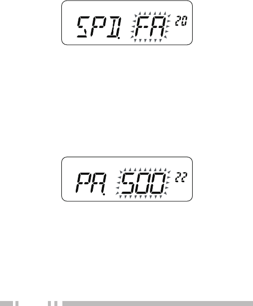
aDjusTing THe DTMF Tone TransMission speeD
This transceiver allows you to configure the DTMF number
transmission speed between Fast (default) and Slow. If a repeater
cannot respond to the fast speed, adjust this parameter.
1 Enter Menu mode and access Menu No. 20 (SPD).
2 Press [MENU] and rotate the Selector (or press [UP]/ [DOWN])
to select “FA” (Fast) or “SL” (Slow).
• The tone duration of FAST is 50 ms and SLOW is 100 ms. “FA”
(Fast) is the default setting.
3 Press [MENU] to store the setting.
aDjusTing THe pause DuraTion
You can change the pause duration (a space digit) stored in
memory channels. The default setting is 500 milliseconds.
1 Enter Menu mode and access Menu No. 22 (PA).
2 Press [MENU] and rotate the Selector (or press [UP]/ [DOWN])
to select 100, 250, 500, 750, 1000, 1500, 2000 ms.
3 Press [MENU] to store the setting.
DTMF lock
Assuming you have a transceiver with the optional speaker
microphone installed and you are carrying it in the holder or bag,
you sometimes may want to disable the keypad to avoid accidental
DTMF transmission. In this case, turn the DTMF Lock function ON.
1 Enter Menu mode and access Menu No. 23 (DT.L).

53
2 Press [MENU] and rotate the Selector (or press [UP]/ [DOWN])
to select “ON”.
3 Press [MENU] to store the setting.

54
AUXILIARY FUNCTIONS
apo (auTo power oFF)
The transceiver switches OFF automatically if no keys or controls
are pressed or adjusted for 30 minutes (default). One minute before
the transceiver switches OFF, warning beeps sound for a few
seconds and “APO” blinks. You can select the APO time from OFF
(disable), 30 (default), 60, 90, 120, or 180 minutes.
1 Enter Menu mode and access Menu No. 8 (APO).
2 Press [MENU] and rotate the Selector (or press [UP]/ [DOWN])
to select the APO time.
3 Press [MENU] to store the setting.
Note:
◆ APO does not function while the transceiver is scanning.
◆ The APO timer starts counting down the time when no key presses,
no control adjustments.
◆ The APO warning beep sounds and “APO” appears 1 minute
before the transceiver turns OFF.
◆ The APO warning beep sounds even if Menu No. 16 (BP) is set to
“OFF”.
reMaining BaTTery capaciTy
You can confirm the remaining battery capacity when you transmit
in low power.
To check the remaining capacity:
1 Press and hold [PTT].
• The bar-graph shows the remaining battery capacity.
55
: High battery power
:
:
:
: Low battery power
No display : Recharge or replace the batteries.
2 Release [PTT] to exit.
Note: You may not be able to transmit at high power if the battery
remaining indicator shows low battery power
■ Battery Life
Before you operate the transceiver outside using a battery pack,
it is important to know how long the battery pack will last. The
operating times listed in the table below are measured under the
following cyclic conditions:
TX: 6 seconds, RX: 6 seconds, Stand-by: 48 seconds
We recommend you carry extra battery packs with you, in case
the battery pack becomes discharged.
Battery Type Output Power Operating Time/ Hours
(Approx.)
PB-43N (7.2 V) H 5.5
L 11.0
BT-14 (9.0 V) H 4.0
L 10.5
BaTTery saver
The Battery Saver extends the operating time of the transceiver. It
automatically activates when the squelch is closed and no key is
pressed for more than 10 seconds. To reduce battery consumption,
this function shuts the receiver circuit OFF for the programmed
time, then momentarily turn it back ON to detect a signal.
To program the receiver shut-off period for the battery saver:
1 Enter Menu mode and access Menu No. 7 (SAV).
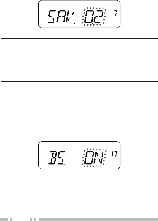
56
2 Press [MENU] and rotate the Selector (or press [UP]/ [DOWN])
to select the receiver shutoff period from OFF, 0.2, 0.4, 0.6, 0.8,
1.0, 2.0, 3.0, 4.0, or 5.0 seconds.
3 Press [MENU] to store the setting.
Note:
◆ The longer the shut-off period, the more you can save on battery
consumption. However, there is a greater chance of missing a
signal.
◆ When the CTCSS/ DCS code matches during reception, the battery
saver function is turned OFF.
◆ Battery Saver does not function while scanning.
BeaT sHiFT
Since the transceiver uses a microprocessor to control various
functions of the transceiver, the CPU clock oscillator’s harmonics or
image may appear on some spots of the reception frequencies {page
73}. In this case, turn the Beat Shift function ON.
1 Enter Menu mode and access Menu No. 17 (BS).
2 Press [MENU] and rotate the Selector (or press [UP]/ [DOWN])
to select “ON”.
3 Press [MENU] to store the setting.
Note: Beat Shift status can be stored to each Memory channel.
57
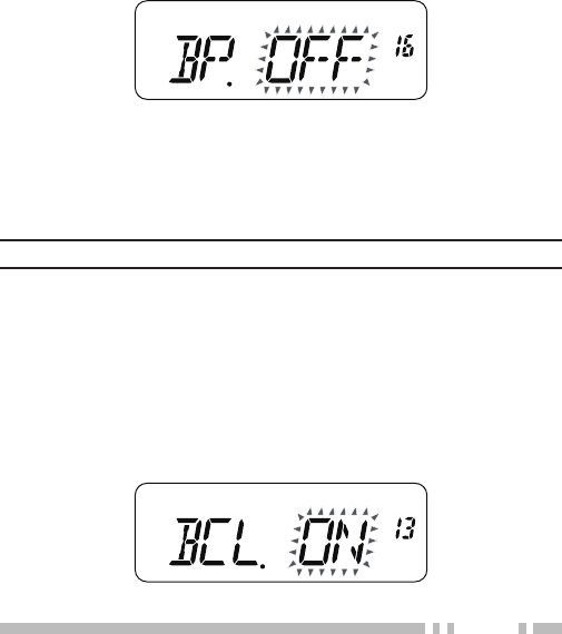
Beep FuncTion
The Beep function provides confirmation of entry, error status,
and malfunctions of the transceiver. We recommend you leave
this function ON in order to detect erroneous operations and
malfunctions.
However, to turn the beep function OFF:
1 Enter Menu mode and access Menu No. 16 (BP).
2 Press [MENU] and rotate the Selector (or press [UP]/ [DOWN])
to select “OFF”.
3 Press [MENU] to store the setting.
The transceiver generates the following warning beeps even if the
beep function is turned OFF.
• APO warning beeps
• Time-Out Timer warning beep
Note: The beep output level is linked to the volume control position.
Busy cHannel lockouT
This function is used in order to prevent transmitting on a channel
or frequency that somebody else is currently using. When turned
ON, an error beep sounds and you cannot transmit even if you
press [PTT].
1 Enter Menu mode and access Menu No. 13 (BCL).
2 Press [MENU] and rotate the Selector (or press [UP]/ [DOWN])
to select “ON” .
3 Press [MENU] to store the setting.
58
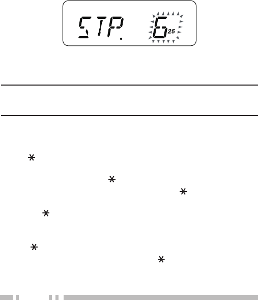
Frequency sTep size
Choosing the correct frequency step size is essential in order to
select your exact receive frequency using the Selector (or [UP]/
DOWN). You can select your desired frequency step size from: 5,
6.25, 10, 12.5, 15, 20, 25, 30, 50, or 100 (kHz).
To change the frequency step size:
1 Press [F], [3].
• The current frequency step size appears.
2 Rotate the Selector (or press [UP]/ [DOWN]) to select your
desired frequency step size.
3 Press [MENU] to store the setting.
Note: If you change to a frequency step size that does not match the
current operating frequency, the transceiver automatically adjusts the
frequency to match the new frequency step size.
Back ligHT
To illuminate the display and keys:
Press [ ].
• If no other key is pressed, the light turns OFF approximately 5
seconds after releasing [ ].
• Press any key (including [PTT]) other than [ ] while the display
and keys are lit to restart the 5-second timer.
• Press [ ] while the display and keys are lit to immediately turn
the light OFF.
To keep the light ON continuously:
Press [ ](1s).
• The light remains ON until you press [ ](1s) again.
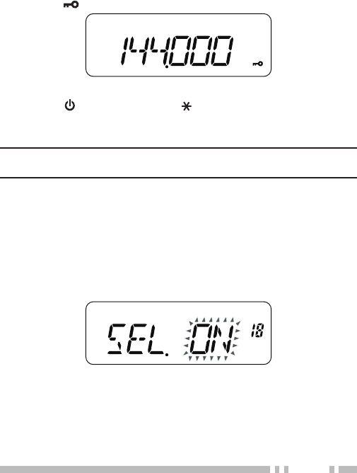
59
lock FuncTion
The lock function disables most of the keys to prevent you from
accidentally activating a function.
1 Press [F], [MENU] to turn the Lock function ON or OFF.
• The “ ” icon appears when the Lock function is ON.
• The following keys cannot be locked:
[F], [ ] (POWER), [PTT], [ ], [MON], Volume control and
microphone PF key.
2 Press [F], [MENU] to unlock the keys.
Note: You cannot perform the Microprocessor Reset {page 71} while
the Lock function is ON.
selecTor unlock
While the Lock function is ON, you sometimes may want to rotate
the Selector (or press [UP]/ [DOWN]) to change the frequency. In
this case, turn the Selector unlock function ON.
1 Enter Menu mode and access Menu No. 18 (SEL).
2 Press [MENU] and rotate the Selector (or press [UP]/ [DOWN])
to select “ON”.
3 Press [MENU] to store the setting.

60
MicropHone key lock
The Microphone Key Lock function will lock the microphone PF
keys.
1 Enter Menu mode and access Menu No. 24 (M.PF.).
2 Press [MENU] and rotate the Selector (or press [UP]/ [DOWN])
to select “ON”.
3 Press [MENU] to store the setting.
MicropHone pF keys (opTional)
If you have an optional SMC-33 or SMC-34 speaker microphone,
you can access many transceiver settings without using transceiver
keys or controls. Microphone keys 1, 2, and 3, located on the top of
the microphone, are programmable with transceiver functions.
The microphone key default assignments are as follows:
Mic [1]: VFO Mic [2]: MR Mic [3]: CALL
Note:
◆ Turn the transceiver OFF before connecting the optional speaker
microphone.
◆ While Menu No. 24 (M.PF.) is “ON” or the Lock function is ON {page
59}, you cannot program PF keys.
◆ If the LOCK switch on the rear of the microphone is ON, you must
move the switch to the OFF position to program the keys.
1 Press one of the following key combinations to reprogram the
keys on the speaker microphone.
• Press Mic [1] + Power ON to reprogram Mic [1].
• Press Mic [2] + Power ON to reprogram Mic [2].
• Press Mic [3] + Power ON to reprogram Mic [3].
2 Press a key or the key combination you want to assign to the
microphone key.

61
Key name [KEY] [F] + [KEY] [KEY]
(1s or 1.5s)
[UP] Volume or Function Up 1−
[DOWN] Volume or Function Down 1−
[MENU] MENU Key lock −
[CALL] CALL CALL IN −
[VFO] VFO MR to VFO −
[MR] MR MR IN −
[MON] MON Squelch level −
[1] Recalling CH 1 Signaling −
[2] Recalling CH 2 Tone frequency −
[3] Recalling CH 3 Frequency step −
[4] Recalling CH 4 DCS code −
[5] Recalling CH 5 CTCSS frequency Speaker
attenuation 2
[6] Recalling CH 6 Priorty scan −
[7] Recalling CH 7 Reverse −
[8] Recalling CH 8 Offset derection −
[9] Recalling CH 9 Channnel lock out −
[0] Recalling CH 0 − −
[ ] Back light On −To keep the
light ON 2
[#] Direct entry Volume adjustment
operation selection −
[PTT] VFO < > MR Transmit power −
Selector Volume or Function Up or Down 1
[REMO 1] 3
~
[REMO 2]
REMO 1
~
REMO 3
REMO 1
~
REMO 3
−
1 After saving a function to a microphone PF key, changing the volume
adjustment operation selection setting of the transceiver will not cause the
operation of the microphone PF key to change.
2 You do not need to continuously hold the PF key.
3 “REMO 1” ~ “REMO 3” are the current settings for the microphone PF keys.
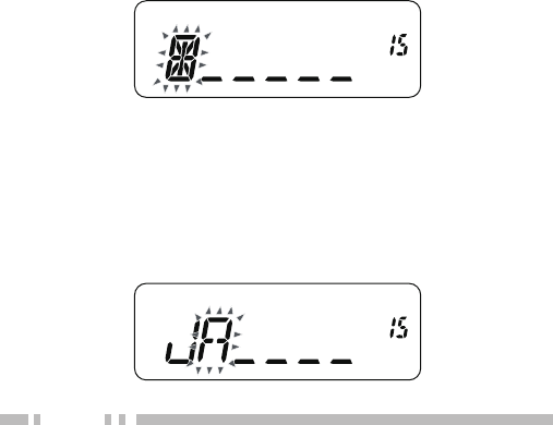
62
MoniTor
When you are receiving while the squelch function is ON, weak
signals may become intermittent. If the CTCSS or DCS function
is ON, you may want to disable the squelch function temporarily to
monitor the current channel activities. In both of these cases, use
the Monitor function to temporarily disable the squelch function.
To activate the Monitor function:
1 Press and hold [MON].
• The speaker is unmuted and you can monitor the signals.
2 Release [MON] to return to normal operation.
power-on Message
You can change the Power-ON Message (a maximum of 6
characters) when the transceiver is turned ON.
1 Enter Menu mode and access Menu No. 15 (P.ON.MSG).
2 Press [MENU].
• A blinking cursor appears.
3 Rotate the Selector (or press [UP]/ [DOWN]) to select a
character.
• You can enter the following alphanumeric characters:
0 ~ 9, A ~ Z, - (hyphen), / (slash) and a space.
4 Press [MENU].
• The cursor moves to the next digit.
5 Repeat steps 3 and 4 to enter up to 6 digits.
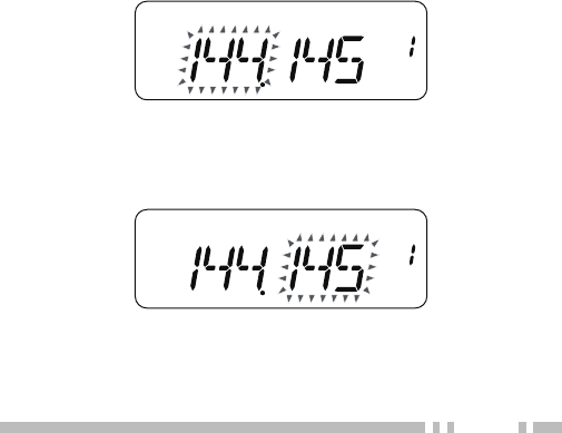
63
• Press [CALL] to delete the character at the current cursor
position.
6 To complete the entry, press [MENU] without selecting a
character. Otherwise press [PTT] to cancel the entry.
prograMMaBle vFo
If you want to limit the operating frequencies within a certain range,
program the upper and lower frequency limits to the programmable
VFO parameters. For example, if you select 144 MHz for the lower
limit and 145 MHz for the upper limit, the tunable range will be
limited from 144.000 MHz to 145.995 MHz.
1 Press [VFO].
2 Enter Menu mode and access Menu No. 1 (P.VFO).
3 Press [MENU].
• The current programmable frequency range for the band
appears.
4 Rotate the Selector (or press [UP]/ [DOWN]) to select the lower
limit frequency in MHz.
5 Press [MENU] to store the lower limit frequency.
• The upper limit frequency blinks.
6 Rotate the Selector (or press [UP]/ [DOWN] to select the upper
limit frequency in MHz.
7 Press [MENU] to store the upper limit frequency.
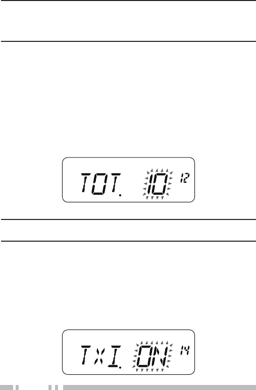
64
Note:
◆ You cannot program the 100 kHz or lower digits.
◆ The upper limit frequency cannot be set lower than the selected
lower limit frequency.
TiMe-ouT TiMer
The Time-out Timer limits the time of each transmission. The built-
in Time-out Timer limits each transmission time to a maximum of
3, 5 or 10 (default) minutes. Just before the transceiver stops the
transmission, a warning beep sounds. This function is necessary to
protect the transceiver from thermal damage and can therefore not
be turned OFF.
1 Enter Menu mode and access Menu No. 12 (TOT).
2 Press [MENU] and rotate the Selector (or press [UP]/ [DOWN])
to select “3”, “5” or “10”.
3 Press [MENU] to store the setting.
Note: A warning beep sounds even if you set Menu No. 16 (BP) to
OFF.
TX inHiBiT
You can inhibit the transmission to prevent unauthorized individuals
from transmitting, or to eliminate accidental transmissions while
carrying the transceiver.
1 Enter Menu mode and access Menu No. 14 (TXI).
2 Press [MENU] and rotate the Selector (or press [UP]/ [DOWN])
to select “ON”.
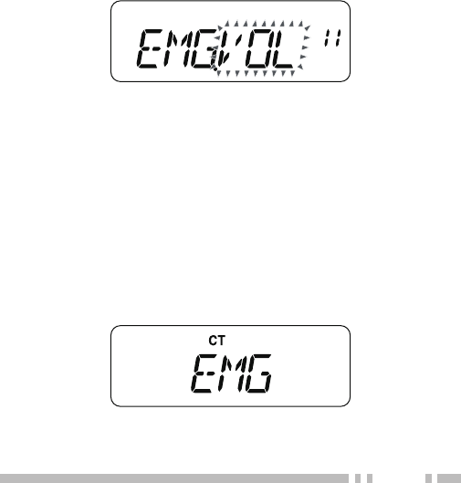
65
3 Press [MENU] to store the setting.
• “TX INH” appears and an error beep sounds if the transceiver
tries to transmit while TX Inhibit is ON.
eMergency siren
Press and hold the [0] key for at least 1.5 seconds to emit the siren
from the speaker at the selected volume level.
To set the Emergency siren volume level:
1 Enter Menu mode and access Menu No. 11 (EMG).
2 Press [MENU] and rotate the Selector (or press [UP]/ [DOWN])
to select “OFF”, “VOL”, “MED” or “MAX”.
OFF: The Emergency siren does not sound.
VOL: The Emergency siren sounds at the same level as the
current volume setting.
MED: The Emergency siren sounds using volume level 20, no
matter what the current volume level setting is.
MAX: The Emergency siren sounds using volume level 31, no
matter what the current volume level setting is.
3 Press [MENU] to store the setting.
■ Using the Emergency Siren
1 Press [0](1.5s), to turn the Emergency siren ON.
• “EMG” appears.
2 Press [0](1.5s) , [PTT] or power OFF, to turn the Emergency
siren OFF.
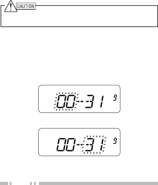
66
• When the Emergency siren sounds, press [PTT] to turn it
OFF (without transmitting).
• While the Emergency siren is sounding and a signal is
being received (as shown by the signal meter), you will be
unable to hear the signal from the speaker.
• You can set the sound volume of the Emergency siren.
• The Emergency siren will continue to sound until it has
been turned OFF.
When using an earphone or headset, do not turn the Emergency
Siren function ON.
MiniMuM/ MaXiMuM voluMe
The transceiver retains the same volume level when the Volume
control is turned to the lowest limit. Maximum Volume level allows
you to limit the volume level to be no higher than the configured
level even if a user attempts to increase the volume level.
1 Enter Menu mode and access Menu No. 9 (VOLUME).
2 Press [MENU] and rotate the Selector (or press [UP]/ [DOWN])
to select the minimum volume level (0 - 31).
3 Press [MENU] and rotate the Selector (or press [UP]/ [DOWN])
to) to select the maximum volume level (0 - 31).
4 Press [MENU] to store the setting.
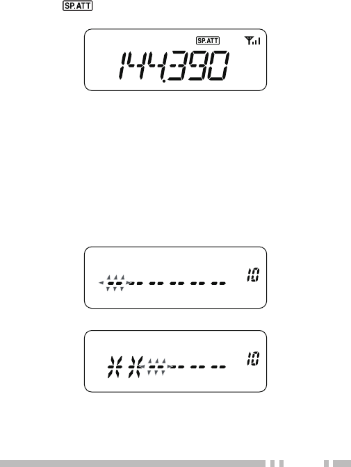
67
speaker aTTenuaTion
Speaker Attenuation decreases the volume level of the Speaker/
Microphone by approximately 10 dB.
1 Press [5](1s) to turn the Speaker Attenuation function ON.
• The “ ” icon appears when the Speaker Attenuation
function is ON.
2 Press [PTT] or [5](1s) to turn the Speaker Attenuation function
OFF.
passworD proTecTion
If password protection is activated, you cannot operate the
transceiver without first entering your password after turning the
transceiver power ON. The password can contain up to 6 digits.
1 Enter Menu mode and access Menu No. 10 (PASSWD).
2 Press [MENU].
• A blinking cursor appears.
3 Press the [0] ~ [9] keys corresponding to the password.
• Password protection will activate when one or more
characters are set.
• Press [CALL] to delete an incorrect character.
68
4 Press [MENU].
• “RE-ENT” appears.
5 Re-enter the same password, for conformation.
6 Press [MENU] to confirm the password.
• If you enter an incorrect password, an error tone sounds and
the transceiver remains locked.
When turning the transceiver power ON while the Password
function is programmed, “PASSWD” appears on the display. You
must enter the password to unlock the transceiver.
To enter the password:
1 Press the [0] ~ [9] keys corresponding to the password.
• Press [CALL] to delete an incorrect character.
2 Press [MENU] to confirm the password.
• If you enter an incorrect password, an error tone sounds and
the transceiver remains locked.

69
OPTIONAL ACCESSORIES
The following options are available for use with this transceiver:
• PB-43N Ni- MH battery pack
• BT-14 Battery case
• SMC-32 Speaker microphone
• SMC-33 Speaker microphone
• SMC-34 Speaker microphone
• HMC-3 Head set
• HMC-4 Head set
• KHS-21 Head set
• EMC-3 Clip microphone
• HS-9 Earphone
• KSC-24 Rapid Charger
Note: Optional accessories for use with this transceiver may change,
post-production. (New options may become available and/or current
options may be discontinued.) Please refer to the options catalog(s) for
applicable transceivers.

70
General InformatIon
This product has been factory aligned and tested to specification
before shipment. Attempting service or alignment without factory
authorization can void the product warranty.
ServIce
When returning this product to your dealer or service center for
repair, pack it in its original box and packing material. Include a full
description of the problem(s) experienced. Include your telephone
number along with your name and address in case the service
technician needs to contact you; if available, also include your fax
number and e-mail address. Don’t return accessory items unless
you feel they are directly related to the service problem. You may
return this product for service to the authorized Kenwood dealer
from whom you purchased it, or any authorized Kenwood service
center. Please do not send subassemblies or printed circuit boards;
send the complete product. A copy of the service report will be
returned with the product.
■ Service Note
If you desire to correspond on a technical or operational problem,
please make your note legible, short, complete, and to the point.
Help us help you by providing the following:
• Model and serial number of equipment
• Question or problem you are having
• Other equipment in your station pertaining to the problem
Do not pack the equipment in crushed newspapers for
shipment! Extensive damage may result during rough handling
or shipping.
MAINTENANCE

71
Note:
◆ Record the date of purchase, serial number and dealer from whom
this product was purchased.
◆ For your own information, retain a written record of any
maintenance performed on this product.
◆ When claiming warranty service, please include a photocopy of the
bill of sale or other proof-of-purchase showing the date of sale.
cleanInG
To clean the case of this product, use a neutral detergent (no strong
chemicals) and a damp cloth.
mIcroproceSSor reSet
If your transceiver seems to be malfunctioning, resetting the
microprocessor may solve the problem. The following 2 reset
Modes are available. When performing the reset, you may lose
memory data and stored information. Back up or write down
important data before performing the reset.
VFO Reset
This resets the transceiver parameters excluding the stored DTMF
Numbers in Memory {page 50} and memory channel contents.
Full Reset
This resets all transceiver parameters to the factory default values.
Note: While operating the transceiver in Channel Display Mode {page
35}, you cannot reset the transceiver.
■ VFO Reset
When the transceiver is turned OFF:
1 Press [PTT] + [VFO] + Power ON.
• The VFO reset confirmation message, “VF.RST?”,
appears.

72
2 Press [VFO] to proceed.
• “SURE ?” appears.
• Press any key other than [ ] or [VFO] to exit the Reset
Mode.
3 Press [VFO] to reset the transceiver.
■ Full Reset
When the transceiver is turned OFF:
1 Press [PTT] + [F] + Power ON.
• The full reset confirmation message, “FL.RST?”, appears.
2 Press [F] to proceed.
• “SURE ? ” appears.
• Press any key other than [ ] or [F] to exit the Reset
Mode.
3 Press [F] to reset the transceiver.

73
operatIon notIceS
The transceiver has been designed and engineered to avoid
possible hardware glitches. However, you may notice the following
symptoms when you operate the transceiver. These symptoms are
not malfunctions.
receIvInG SIGnalS In cItIeS
When you receive signals in cities, the receiver’s entire antenna
indicator may light up without receiving any strong signals. This
happens when the RF amplifier in the receiver is overloaded by
strong interference signals that are nearby.
tranSmISSIon
If you continuously transmit for more than 8 minutes at high power (5
W), the transceiver becomes warm.
If you continue or repeat the transmission before the transceiver
cools down, the thermal protector gradually decreases the output
power down to 1.5 W.
Internal BeatS
On some spots of the frequency, the antenna indicator moves
without receiving any signals or you cannot receive any signals.
This is inevitable when you use super-heterodyne receivers. If this
happens, access Menu No. 17 (BS) and select “ON”.
Internal Beats Frequency
140.800 MHz, 153.600 MHz, 166.400 MHz, 168.350 MHz

74
TROUBLESHOOTING
The problems described in this table are commonly encountered
operational malfunctions and are usually not caused by circuit
failure.
Problem Solution
Nothing appears on the display
when the transceiver is switched
ON, or the display is blinking ON
and OFF.
The battery pack is discharged.
Recharge the battery pack or
replace the batteries.
Most keys and the Selector do
not function.
Transceiver Lock function is
ON (the “ ” icon is visible).
Press [F], [MUNU] to turn OFF
Transceiver Lock.
The transceiver is in Channel
Display Mode. Press [PTT] +
[MR] + Power ON to exit Channel
Display Mode.
You cannot recall any memory
channel.
You have stored no data in any of
the memory channels. Store the
desired frequencies in the memory
channels.
You cannot select the exact
desired frequency using the
selector.
The current frequency step size
does not allow the frequency to be
selected. Select an appropriate
frequency step size. Press [F], [3]
to change the frequency step size.
Programmable VFO frequency
range is too narrow. Expand the
frequency range in Menu No. 1
(P.VFO).
Increasing the Volume control
does not allow you to hear audio.
The selective call function (CTCSS
or DCS) is ON. Turn OFF the
selective call function.

75
Problem Solution
You cannot transmit by pressing
[PTT].
You selected a frequency outside
the allowable range. Select a
frequency within the
allowable transmit frequency
range.
You selected a transmit offset
that places the transmit frequency
outside the limit. Select a proper
offset direction or offset frequency.
TX inhibit is ON. Access Menu
No.14 (TXI) and select “OFF”.
The battery pack voltage is too low
to transmit. Change or replace
the battery.
Repeater cannot be accessed.
Wrong tone frequency is selected.
Select a proper repeater access
tone.
Wrong repeater offset frequency
is selected. Access Menu No.
2 (OFFSET) and select an
appropriate offset frequency.
Wrong offset direction is selected.
Try other offset directions.
DTMF tone cannot be
transmitted.
DTMF Lock is ON. Access Menu
No. 23 (DT.L) and select “OFF”.

76
Problem Solution
The transceiver switches OFF for
no apparent reason.
The Automatic Power OFF (APO)
function is ON. Access Menu No.
8 (APO) and select your desired
time length or “OFF”.
The transceiver returns to
Reception Mode during a long
transmission.
The transmission time exceeded
the programmed TOT time.
Access Menu No. 12 (TOT) to
select your desired transmission
length. The TOT cannot be turned
OFF, protecting the transceiver
from the thermal damage.
The Scan function does not
resume scanning after the
transceiver detects a signal.
You have selected “SE” (SEEK)
for Menu No. 3 (SCAN). Select
either “TO” (Time-Operated) or
“CO” (Carrier-Operated) for Menu
No. 3 (SCAN).
77
SPECIFICATIONS
Note: All specifications (General, Transmitter and Receiver) are
guaranteed within the amateur radio band.
General
Antenna impedance 50 Ω
Operating Voltage DC 6.0 ~ 9.0 V
(7.5 V nominal)
Current
Transmit with H,
7.2 V (PB-43N) Less than 2.0 A
Transmit with L,
7.2 V (PB-43N) Less than 0.8 A
Receive (no signal) Less than 100 mA
Battery Saver ON
(Average) Less than 30 mA
Usable temperature range
–10°C - +50°C
0°C - +40°C
(with charging Ni-MH battery)
Frequency stability Within 5ppm
(–20°C ~ 60°C)
Dimensions
(W x H x D including Projections)
58.0 x 120.1 x 37.8 mm
2 9/32 x 4 3/4 x 1 31/64 inches
with PB-43N
58.0 x 120.1 x 39.0 mm
2 9/32 x 4 3/4 x 1 1/2 inches
with BT-14
Weight (Approx.)
250 g/ 8.8 oz.
with PB-43N
259 g/ 9.1 oz.
with BT-14

78
Transmitter
Transmission Mode F3E
Frequency range
K type 144 ~ 148 MHz
M type 136 ~ 174 MHz
Output Power
PB-43N (7.2 V)
H: 5.0 W (approx.)
L: 0.5 W (approx.)
BT-14 (9.0 V)
H: 3.5 W (approx.)
L: 0.3 W (approx.)
Modulation Reactance
Maximum frequency deviation 5 kHz
Spurious emissions -60 dB or less (H power)
-50 dB or less (L power)
Microphone impedance 2 kΩ

79
Receiver
Reception Mode F3E
Intermediate Frequency (IF) 1st IF: 38.85 MHz
2nd IF: 450 kHz
Circuit type Doublesuper-heterodyne
Sensitivity
FM (12 dB SINAD) 2 m amateur
radio band:
Less then 0.18 µV
Squelch sensitivity Less then 0.13 µV (within 2 m
amateur radio band)
Selectivity
Less then -6 dB/ 10 kHz Less
then --40 dB/ 28 kHz (within 2
m amateur radio band)
Audio output (10% distortion) More than 400 mW
(7.2 V, 8 Ω load)