JVCKENWOOD 422400 UHF DIGITAL BASE-REPEATER User Manual
JVC KENWOOD Corporation UHF DIGITAL BASE-REPEATER
User Manual

NXR-710/ NXR-810
INSTRUCTION MANUAL
© B62-2199-00 (K)
09 08 07 06 05 04 03 02 01 00
MANUAL DE INSTRUCCTIONES
MODE D'EMPLOI
BASE-REPETIDOR DIGITAL VHF / BASE-REPETIDOR DIGITAL UHF
VHF DIGITAL BASE-REPEATER/ UHF DIGITAL BASE-REPEATER
BASE-RELAIS NUMÉRIQUE VHF/BASE-RELAIS NUMÉRIQUE UHF
◆ Thisrepeaterisintendedforuseasaxedbasestationwith
the antenna located outdoors on the rooftop or on an antenna
tower.
◆ Thisrepeaterisdesignedfora13.6VDCpowersource!
Neverusea24VDCorhighersourcetopowertherepeater.
◆ UseonlythesuppliedDCcord.
◆ DonotremovetheferritecoreattachedtotheDCcord.Doing
somaycauseinterferencewithradiocommunications.
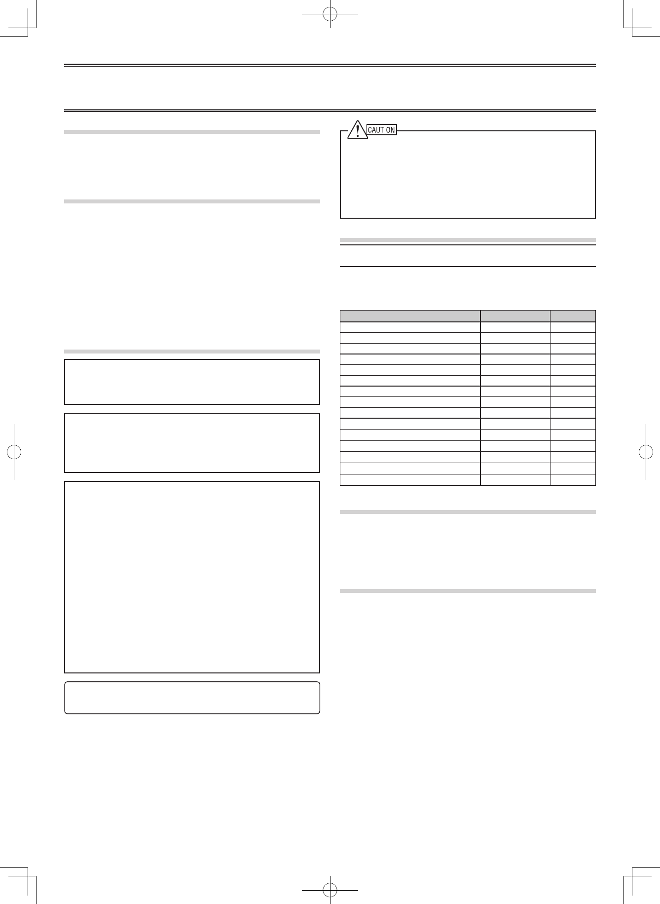
UNPACKING AND CHECKING EQUIPMENT
Note:ThefollowingunpackinginformationisforusebyyourKenwood
dealer, an authorized Kenwoodservicecenter,orthefactory.
Carefullyunpacktherepeater.Werecommendthatyouidentify
theitemslistedinthefollowingtablebeforediscardingthe
packingmaterial.Ifanyitemsaremissingorhavebeendamaged
duringshipment,leaclaimwiththecarrierimmediately.
Item Part Number Quantity
Hardwarexture J21-8559-XX 1
Front glass B10-2635-XX 1
Name plates B11-1259-XX 1
Cushion G13-1801-XX 4
Cushion G13-1802-XX 4
Foot J02-0475-XX 2
Foot J02-0492-XX 2
Grommet J59-0302-XX 2
Handle K01-0418-XX 1
Screws N30-4006-XX 2
Screws N35-3006-XX 5
DC cord E30-3427-XX 1
Leadwirewithconnector(15pin) E31-3228-XX 1
Fuse F05-1537-XX 1
Instruction Manual B62-2199-XX 1
INSTALLATION
To install the handles onto the front panel of the repeater, align
thehandleswiththeholesonthefrontpanel,thensecurethe
handlesusingthesuppliedscrews.
Please consult your dealer for installing the repeater and
antenna.
MICROPHONE
Connect an optional KMC-30, KMC-35, KMC-27A, KMC-27B,
or KMC-9C Kenwood microphone to the MICjackonthefront
panel.
◆ Governmentlawprohibitstheoperationofunlicensedradio
transmitterswithintheterritoriesundergovernmentcontrol.
◆ Illegaloperationispunishablebyneand/orimprisonment.
◆ Referservicetoqualiedtechniciansonly.
FCC WARNING
Thisequipmentgeneratesorusesradiofrequencyenergy.Changes
ormodicationstothisequipmentmaycauseharmfulinterference
unlessthemodicationsareexpresslyapprovedintheinstruction
manual.Theusercouldlosetheauthoritytooperatethisequipmentif
anunauthorizedchangeormodicationismade.
INFORMATION TO THE DIGITAL DEVICE USER REQUIRED BY
THE FCC
Thisequipmenthasbeentestedandfoundtocomplywiththelimits
foraClassBdigitaldevice,pursuanttoPart15oftheFCCRules.
Theselimitsaredesignedtoprovidereasonableprotectionagainst
harmfulinterferenceinaresidentialinstallation.
This equipment generates, uses and can generate radio frequency
energyand,ifnotinstalledandusedinaccordancewiththe
instructions,maycauseharmfulinterferencetoradiocommunications.
However,thereisnoguaranteethattheinterferencewillnotoccur
inaparticularinstallation.Ifthisequipmentdoescauseharmful
interferencetoradioortelevisionreception,whichcanbedetermined
byturningtheequipmentoffandon,theuserisencouragedtotryto
correcttheinterferencebyoneormoreofthefollowingmeasures:
• Reorientorrelocatethereceivingantenna.
• Increasetheseparationbetweentheequipmentandreceiver.
• Connect the equipment to an outlet on a circuit different from that to
whichthereceiverisconnected.
• Consultthedealerfortechnicalassistance.
THANK YOU!
WearegratefulyoupurchasedthisKenwoodrepeater.We
believethiseasy-to-programrepeaterwillbehighlyeffectivein
yourcommunicationssystem,andwillkeeppersonneloperating
atpeakefciency.
PRECAUTIONS
• Donotexposetheunittorainormoisture;topreventreor
electricshock.
• Donotopentheunitunderanycircumstances;toavoidrisk
ofelectricshock.
• Donotexposetheunittolongperiodsofdirectsunlight,nor
placeitclosetoheatingappliances.
• Donotplacetheunitinexcessivelydustyand/orhumid
areas,noronunstablesurfaces.
• Ifyoudetectanabnormalodororsmokecomingfromthe
unit,disconnectthepowerfromtheunitimmediately.Contact
your Kenwood servicecenterordealer.
NOTICES TO THE USER
NXR-710 / NXR-810 INSTRUCTION MANUAL
VHF DIGITAL BASE-REPEATER / UHF DIGITAL BASE-REPEATER
The AMBE+2TMvoicecodingTechnologyembodiedinthisproduct
isprotectedbyintellectualpropertyrightsincludingpatentrights,
copyrightsandtradesecretsofDigitalVoiceSystems,Inc.Thisvoice
codingTechnologyislicensedsolelyforusewithinthisCommunications
Equipment.TheuserofthisTechnologyisexplicitlyprohibitedfrom
attemptingtoextract,remove,decompile,reverseengineer,or
disassembletheObjectCode,orinanyotherwayconverttheObject
Codeintoahuman-readableform.U.S.PatentNos.#5,870,405,
#5,826,222,#5,754,974,#5,701,390,#5,715,365,#5,649,050,
#5,630,011,#5,581,656,#5,517,511,#5,491,772,#5,247,579,#5,226,084
and#5,195,166.
Firmware Copyrights
Thetitletoandownershipofcopyrightsforrmwareembeddedin
KenwoodproductmemoriesarereservedforKenwoodCorporation.
REPEATER OPERATION
Note: Pleaseconsultyourdealerforprogrammingtherepeater.
Whenpowerisappliedtotheunit,thePOWERindicatorlights:
・GreenwhenusingthemainDCjack.
Rotate the VOLUMEcontroltoadjusttheaudio.
The BUSYindicatorlightsgreenwhilereceivingasignalandthe
TXindicatorlightsredwhiletransmitting.
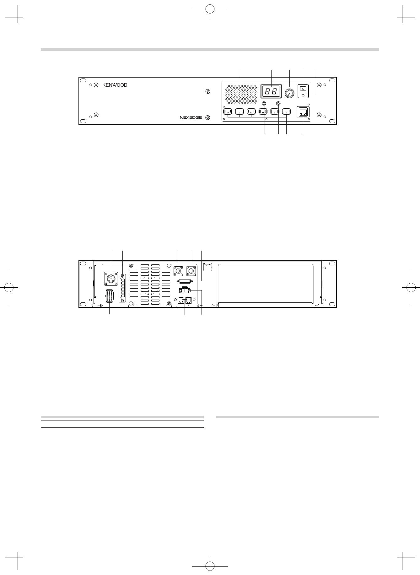
■ Rear Panel
q TX OUT jack
ConnectaTXantennaoraduplexertothisreceptacle.
w CONTROL I/O jack
Connect a repeater controller or a remote panel to this
DB-25interface.
e REF IN jack
Connecttoa10MHzexternaloscillator.
r RX IN jack
ConnectanRXantennaoraduplexertothisBNC
receptacle.
CONTROLS AND FUNCTIONS
■ Front Panel
qwr
y
u
i
o
e
t FUSE
Insert15Abladefuseintothisfuseholder.
y DC 13.6V jack
Connecta13.6VDCpowersupplytothisjack.
u N SYNC 1 / 2 jack
Thisjackiscurrentlynotused.Youcanconnectanother
repeaterhereforfuturefunctions.
i TEST/SPKR jack
Testinput/outputjack.Connectanexternalspeakerto
thisjack.
TRANSCEIVER OPERATION
■ Receive
Adjustthevolumetoyourdesiredlevel.Youmayneedto
readjustthevolumeifyouarehavinginterferencewhile
receivingamessagefromyourdispatcheroranothermember
inyoureet.
The BUSYindicatorlightsgreenwhileasignalisbeing
received.
■ Transmit
1 Listentothechannelbeforetransmitting,tomakesureit
isnotbeingused.
2 Press the microphone PTTswitch,thenspeakinyour
normalspeakingvoice.
The TXindicatorlightsredwhiletransmitting.
3 Whenyounishspeaking,releasethePTTswitch.
q Speaker
w CH/STATUS Display
Two7-segmentdigitsdisplaythechannelnumber,name,
orstatus.
e VOLUME control
Rotatetoadjusttheaudio.
r POWER switch
t POWER indicator
LightsgreenwhenpowerissuppliedtotheDC 13.6V
jack.
y MIC jack
Connectamicrophonetothis8-pinmodularjack.
u Programmable Function keys
Pressthesekeystoactivatetheirprogrammable
functions.
i BUSY indicator
Lightsgreenwhileasignalisbeingreceived.
o TX indicator
Lightsredwhiletransmitting.
CH/STATUS
VOLUME
BUSY
TX POWER
MIC
FUSE
N SYNC
DC 13.6V
REF IN RX IN
TX OUT CONTROL
I/O
TEST/SPKR
t
qwrt
y
u
e
i


TERMINAL
MIC(Modular Jack)
P
in Numbe
r
Pin Name Description Specification I/O notes
1NC
2 SB Power Output 13.6V
3 GND GND GND
4 PTT PTT Signal/
TXD2 As
y
nchronous Send Input Impeadance 22kΩI/O
5 MICG MIC GND MIC GND
6 MIC MIC Input 600ΩI
7 HOOK
H
oo
k
D
e
t
ec
ti
on
/
RXD2 Asynchronous Receive
Data
Input Impeadance 100kΩI
8NC
TEST/SPEAKER CONNECTOR
P
in Numbe
r
Pin Name Description Specification I/O notes
1 SB Power Output 13.6V
2 SB Power Output 13.6V
3NC
4 GND GND GND
5 GND GND GND
6 SPG Speaker GND Speaker GND
7 RD RX Audio Output 60% Deviation O
8 RSSI RSSI Signal Output Output Level 0 or 3.3V O
9 SPI Internal Speaker Input Short with "SPO" I
10 AO1 Open Collector Terminal Allowable current value MAX O
11 AO2 Open Collector Terminal Allowable current value MAX O
12 SPO External Speaker Output Output Level 4W (5% Distortion) O
13 AO3 Open Collector Terminal Allowable current value MAX O
14 AO4 Open Collector Terminal Allowable current value MAX O
15 AO5 Open Collector Terminal
Allowable
current
value
MAX
200mA
O
Control I/O (D-SUB 25Pin) CONNECTOR
P
in Numbe
r
Pin Name Description Specification I/O notes
1NC
2 RXD0 Asynchronius Receive Data Conform to RS-232C standard I
3 TXD0 Asynchronius Send Data Conform to RS-232C standard O
4 AI1 Programmable Function Input 1 Input Impeadance 47kΩI
5AI2 Pro
g
rammable Function In
p
ut 2 In
p
ut Im
p
eadance 47kΩI
6AI3 Pro
g
rammable Function In
p
ut 3 In
p
ut Im
p
eadance 47kΩI
7 DG Digital GND Digital GND
8 TD TX DATA Input Input Impeadance 600ΩI signalling
9 TA TX Audio Input Input Impeadance 600ΩI voice
10 RD RX DATA Output 60% Deviation O signalling
11 RA RX Audio Output 60% Deviation O voice
12 RXG RX Signal GND RX Signal GND
13 SPM Speaker Mute Input Impeadance 47kΩI
14 BER_CLK For Bit Error Rate Clock CMOS O
15 EMON External Monitor Switch Input Impeadance 47kΩI
16 EPTT External PTT Switch Input Impeadance 47kΩI
17 SC Squelch Control Output Level 0 or 5V O
18 BER_DAT For Bit Error Rate Data CMOS O
19 TXG TX Signal GND TX Signal GND
20 IO1 Programmable Function I/O 1 Input Impeadance 47kΩ/
Out
p
ut Level 0 or 5V I/O
21 IO2 Programmable Function I/O 2 Input Impeadance 47kΩ/
Out
p
ut Level 0 or 5V I/O
22 IO3 Programmable Function I/O 3 Input Impeadance 47kΩ/
Out
p
ut Level 0 or 5V I/O
23 IO4 Programmable Function I/O 4 Input Impeadance 47kΩ/
Out
p
ut Level 0 or 5V I/O
24 IO5 Programmable Function I/O 5 Input Impeadance 47kΩ/
Out
p
ut Level 0 or 5V I/O
25 IO6 Programmable Function I/O 6 Input Impeadance 47kΩ/
Out
p
ut Level 0 or 5V I/O
N-SYNC Connector (There are two connectors)
P
in Numbe
r
Pin Name Description Specification I/O notes
1 N_SYNC1_B RS-485 Diffrential Signal B Conform to RS485 I/O Connector#1,2
2 N_SYNC1_A RS-485 Diffrential Signal A Conform to RS485 I/O Connector#1,2
3 N_SYNC2_B RS-485 Diffrential Signal B Conform to RS485 I/O Connector#1,2
4 N_SYNC2_
A
RS-485 Diffrential Signal A Conform to RS485 I/O Connector#1,2
RX IN RX antenna terminal(BNC Receptacle)
TX OUT TX antenna terminal(N Receptacle)
REF IN Reference CLK input treminal(BNC Receptacle)
MANDATORY SAFETY INSTRUCTIONS TO INSTALLERS AND USERS
• Use only manufacturer or dealer supplied antenna.
• Antenna Minimum Safe Distance: 120 cm (4 feet), 50% duty Cycle.
• Antenna Gain: 0 dBd referenced to a dipole.
The Federal Communications Commission has adopted a safety standard for human
exposure to RF (Radio Frequency) energy which is below the OSHA (Occupational Safety
and Health Act) limits.
• Antenna Mounting: The antenna supplied by the manufacturer or radio dealer must not be
mounted at a location such that during radio transmission, any person or persons can
come closer than the above indicated minimum safe distance to the antenna, i.e. 120 cm
(4 feet) , 50% duty Cycle.
• To comply with current FCC RF Exposure limits, the antenna must be installed at or
exceeding the minimum safe distance shown above, and in accordance with the
requirements of the antenna manufacturer or supplier.
• Vehicle installation: The antenna can be mounted at the center of a vehicle metal roof or
trunk lid, if the minimum safe distance is observed.
• Base Station Installation: The antenna should be fixed-mounted on an outdoor permanent
structure. RF Exposure compliance must be addressed at the time of installation.
Antenna substitution: Do not substitute any antenna for the one supplied or recommended
by the manufacturer or radio dealer.
You may be exposing person or persons to excess radio frequency radiation. You may
contact your radio dealer or the manufacturer for further instructions.
Maintain a separation distance from the antenna to person(s) of at least
120 cm (4 feet) , 50% duty Cycle.
You, as the qualified end-user of this radio device must control the exposure conditions of
bystanders to ensure the minimum separation distance (above) is maintained between the
antenna and nearby persons for satisfying RF Exposure compliance. The operation of this
transmitter must satisfy the requirements of Occupational/Controlled Exposure
Environment, for work-related use, transmit only when person(s) are at least the minimum
distance from the properly installed, externally mounted antenna. Transmit only when
people outside the vehicle are at least the recommended minimum lateral distance away
from the antenna/vehicle