JVCKENWOOD 431201 UHF Digital Transceiver User Manual Instruction Manual
JVC KENWOOD Corporation UHF Digital Transceiver Instruction Manual
Instruction Manual

NX-720 Series
NX-820 Series
VHF DIGITAL TRANSCEIVER
UHF DIGITAL TRANSCEIVER
INSTRUCTION MANUAL
ÉMETTEUR-RÉCEPTEUR NUMÉRIQUE VHF
ÉMETTEUR-RÉCEPTEUR NUMÉRIQUE
UHF
MODE D’EMPLOI
TRANSCEPTOR DIGITAL VHF
TRANSCEPTOR DIGITAL UHF
MANUAL DE INSTRUCCIONES
© B62-2421-00 (K)
09 08 07 06 05 04 03 02 01 00

VHF DIGITAL TRANSCEIVER
UHF DIGITAL TRANSCEIVER
NX-700 Series
NX-800 Series
INSTRUCTION MANUAL
ENGLISH
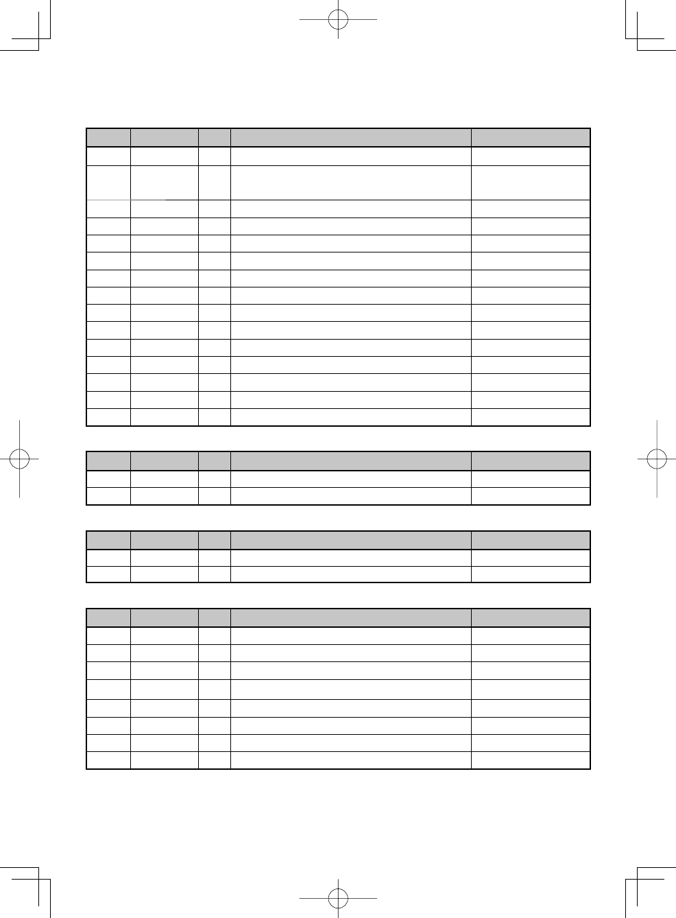
Terminal Descriptions
ACC (D-SUB 15 Pin Connector)
Pin No. Name I/O Description Specification
1 SB O DC Power (Switched B) Output 13.6 V ±15% Max. 2 A
2 IGN I Igintion Signal Input Min. Input: 10.8 V
Max. Input: 16.0 V
3 SP2 O Loudspeaker Output 4 Ω
4 DETO O RX Detected Audio Output 280 mVp-p (typ.)
5 DATAI I TX Data Input 100 kΩ
6 FNC1/ TXD I/O Programmable/ PC Serial Data from Radio High Impedance
7 FNC1/ RXD I/O Programmable/ PC Serial Data to Radio High Impedance
8 FNC3 I/O Programmable High Impedance
9 FNC4 I/O Programmable High Impedance
10 FNC5 I/O Programmable High Impedance
11 FNC6 I/O Programmable High Impedance
12 50MC O DC Power Output 5 V, Max 100 mA
13 HR1 O Horn Alert Signal Output Max 3 A
14 HR2 O Horn Alert Signal Output Max 3 A
15 GND — Ground Ground
Speaker Jack (3.5 mm Phone Jack) 4 W/ 4 Ω
Pin No. Name I/O Description Specification
1 SPO O External Speaker Output 4 Ω
3 GND — Ground Ground
DC Input Connector
Pin No. Name I/O Description Specification
Red B I DC Power Input 13.6 V ±15%
Black GND I Ground Ground
Microphone Jack
Pin No. Name I/O Description Specification
1 BLC O Backlight Control High Impedance
2 SB O DC Power (Switched B) Output 13.6 V ±15%
3 GND — Ground Ground
4 PTT/ TXD I/O PTT/ PC Serial Data from Radio High Impedance
5 ME — Mic Ground Ground
6 MIC I Mic Signal Input 600 Ω
7 HOOK/ RXD I Hook/ PC Serial Data to Radio High Impedance
8 DM I/O Mic Data Detection High Impedance
Antenna Terminal
50 Ω impedance
GPS Terminal <GPS model olny>
50 Ω impedance
i
One or more of the following statements may be applicable:
FCC WARNING
This equipment generates or uses radio frequency energy. Changes or modifications to this
equipment may cause harmful interference unless the modifications are expressly approved in the
instruction manual. The user could lose the authority to operate this equipment if an unauthorized
change or modification is made.
INFORMATION TO THE DIGITAL DEVICE USER REQUIRED BY THE FCC
This equipment has been tested and found to comply with the limits for a Class B digital device,
pursuant to Part 15 of the FCC Rules. These limits are designed to provide reasonable protection
against harmful interference in a residential installation.
This equipment generates, uses and can generate radio frequency energy and, if not installed and
used in accordance with the instructions, may cause harmful interference to radio communications.
However, there is no guarantee that the interference will not occur in a particular installation. If this
equipment does cause harmful interference to radio or television reception, which can be determined
by turning the equipment off and on, the user is encouraged to try to correct the interference by one
or more of the following measures:
• Reorient or relocate the receiving antenna.
• Increase the separation between the equipment and receiver.
• Connect the equipment to an outlet on a circuit different from that to which the receiver is
connected.
• Consult the dealer for technical assistance.
THANK YOU
We are grateful you have chosen KENWOOD for your personal mobile applications.
This instruction manual covers only the basic operations of your mobile radio. Ask your dealer for
information on any customized features they may have added to your radio.
NOTICES TO THE USER
◆ Government law prohibits the operation of unlicensed transmitters within the territories under
government control.
◆ Illegal operation is punishable by fine and/or imprisonment.
◆ Refer service to qualified technicians only.
SAFETY: It is important that the operator is aware of, and understands, hazards
common to the operation of any transceiver.
◆ EXPLOSIVE ATMOSPHERES (GASES, DUST, FUMES, etc.)
Turn OFF your transceiver while taking on fuel or while parked in gasoline service stations. Do
not carry spare fuel containers in the trunk of your vehicle if your transceiver is mounted in the
trunk area.
◆ INJURY FROM RADIO FREQUENCY TRANSMISSIONS
Do not operate your transceiver when somebody is either standing near to or touching the
antenna, to avoid the possibility of radio frequency burns or related physical injury.
◆ DYNAMITE BLASTING CAPS
Operating the transceiver within 500 feet (150 m) of dynamite blasting caps may cause them
to explode. Turn OFF your transceiver when in an area where blasting is in progress, or where
“TURN OFF TWO-WAY RADIO” signs have been posted. If you are transporting blasting caps
in your vehicle, make sure they are carried in a closed metal box with a padded interior. Do not
transmit while the caps are being placed into or removed from the container.
ii
CONTENTS
GETTING STARTED ......................................................................................1
GETTING ACQUAINTED ...............................................................................3
PROGRAMMABLE FUNCTIONS ...................................................................5
BASIC OPERATIONS ....................................................................................6
SCAN..............................................................................................................8
FleetSync: ALPHANUMERIC 2-WAY PAGING FUNCTION ........................10
TRUNKING CALLS (ANALOG) ....................................................................12
ADVANCED OPERATIONS .........................................................................13
BACKGROUND OPERATIONS ...................................................................17
PRECAUTIONS
Observe the following precautions to prevent fire, personal injury, and transceiver
damage.
• Do not attempt to configure the transceiver while driving; it is too dangerous.
• Do not disassemble or modify the transceiver for any reason.
• Do not expose the transceiver to long periods of direct sunlight, nor place it near heating
appliances.
• If an abnormal odor or smoke is detected coming from the transceiver, switch the
transceiver power off immediately, and contact your KENWOOD dealer.
• Use of the transceiver while you are driving may be against traffic laws. Please check
and observe the vehicle regulations in your area.
• Do not use options not specified by KENWOOD.
◆ The transceiver operates in 12 V negative ground systems only! Check the battery polarity and
voltage of the vehicle before installing the transceiver.
◆ Use only the supplied DC power cable or a KENWOOD optional DC power cable.
◆ Do not cut and/or remove the fuse holder on the DC power cable.
For passenger safety, install the transceiver securely using the supplied mounting bracket and
screw set so the transceiver will not break loose in the event of a collision.
1
GETTING STARTED
Note: The following instructions are for use by your KENWOOD dealer, an authorized KENWOOD
service facility, or the factory.
SUPPLIED ACCESSORIES
Carefully unpack the transceiver. We recommend that you identify the items listed below
before discarding the packing material. If any items are missing or have been damaged
during shipment, file a claim with the carrier immediately.
DC power cable (with fuses). . . . . . . . . . . . . . . . . . . . . . . . . . . . . . . . . . . . . . . . . . . . . . . . . . . . . .1
• 15 A fuse . . . . . . . . . . . . . . . . . . . . . . . . . . . . . . . . . . . . . . . . . . . . . . . . . . . . . . . . . . . . . . . . . 2
Mounting Bracket . . . . . . . . . . . . . . . . . . . . . . . . . . . . . . . . . . . . . . . . . . . . . . . . . . . . . . . . . . . . . .1
Screw set
• 5 x 16 mm self-tapping screw. . . . . . . . . . . . . . . . . . . . . . . . . . . . . . . . . . . . . . . . . . . . . . . . . .4
• Hex-headed screw with washer . . . . . . . . . . . . . . . . . . . . . . . . . . . . . . . . . . . . . . . . . . . . . . . . 4
• Spring washer . . . . . . . . . . . . . . . . . . . . . . . . . . . . . . . . . . . . . . . . . . . . . . . . . . . . . . . . . . . . . 4
• Flat washer. . . . . . . . . . . . . . . . . . . . . . . . . . . . . . . . . . . . . . . . . . . . . . . . . . . . . . . . . . . . . . . . 4
Microphone (with cable)
• KMC-35 . . . . . . . . . . . . . . . . . . . . . . . . . . . . . . . . . . . . . . . . . . . . . . . . . . . . . . . . . . . . . . . . . . 1
Microphone hanger (with 4 x 16 mm self-tapping screws) . . . . . . . . . . . . . . . . . . . . . . . . . . . . . . . 1
Instruction manual . . . . . . . . . . . . . . . . . . . . . . . . . . . . . . . . . . . . . . . . . . . . . . . . . . . . . . . . . . . . .1
PREPARATION
Various electronic equipment in your vehicle may malfunction if they are not properly protected
from the radio frequency energy which is present while transmitting. Typical examples include
electronic fuel injection, anti-skid braking, and cruise control. If your vehicle contains such
equipment, consult the dealer for the make of vehicle and enlist his/her aid in determining if they
will perform normally while transmitting.
■ Power Cable Connection
The transceiver operates in 12 V negative ground systems only! Check the battery polarity and
voltage of the vehicle before installing the transceiver.
1 Check for an existing hole, conveniently located in the firewall, where the power
cable can be passed through.
• If no hole exists, use a circle cutter to drill a hole, then install a rubber grommet.
2 Run the power cable through the firewall and into the engine compartment.
3 Connect the red lead to the positive (+) battery terminal and the black lead to the
negative (–) battery terminal.
• Place the fuse as close to the battery as possible.
4 Coil the surplus cable and secure it with a retaining band.
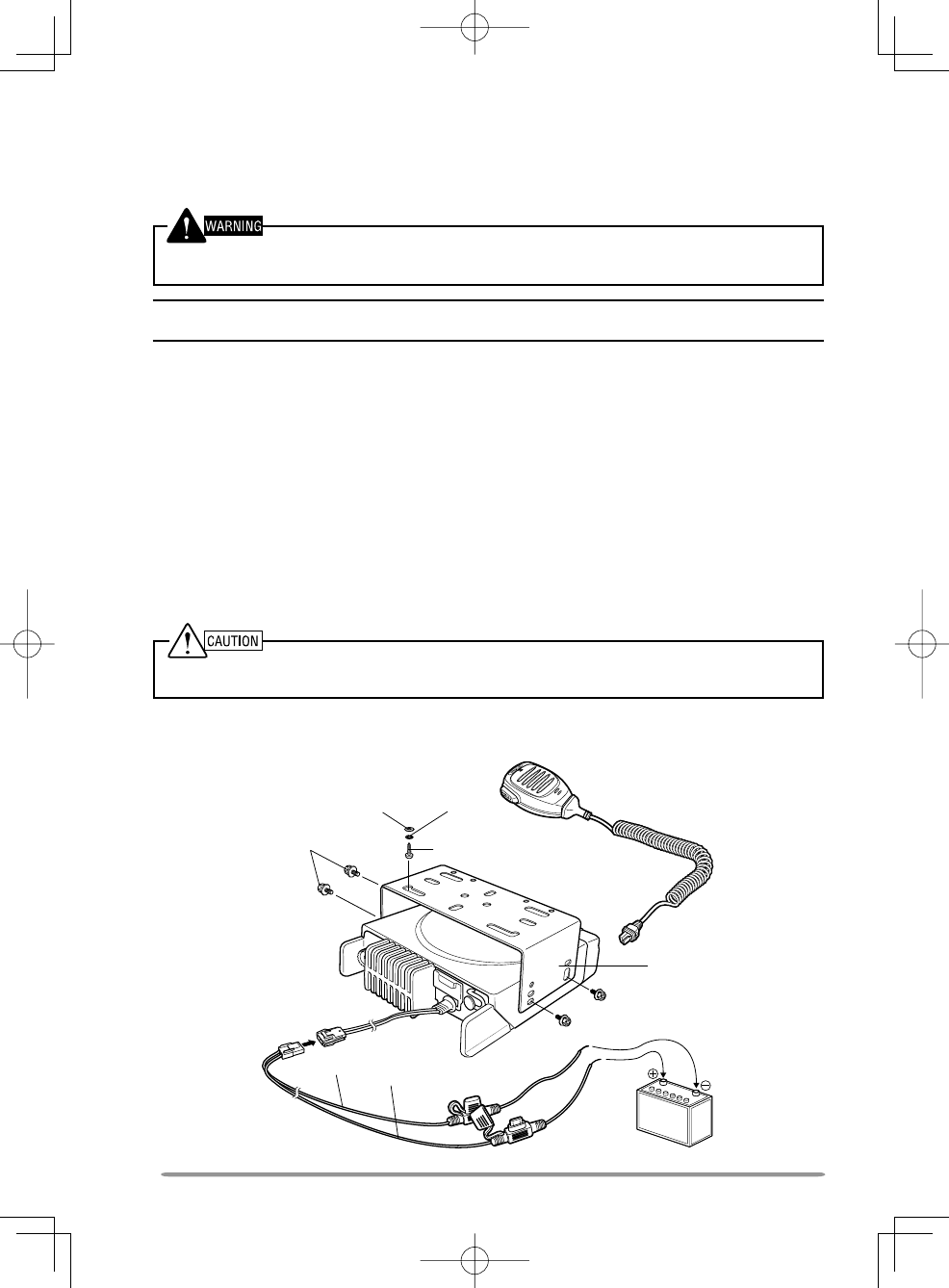
2
M4 x 6 mm
Hex-headed screw
DC power cable
Mounting bracket
Antenna
connector
Power input
connector
Fuse
Black (–) cable
Red (+) cable 12 V vehicle
battery
Microphone
5 x 16 mm
Self-tapping screw
Spring
washer
Flat
washer
• Be sure to leave enough slack in the cables so the transceiver can be removed
for servicing while keeping the power applied.
■ Installing the Transceiver
For passenger safety, install the transceiver securely using the supplied mounting bracket and
screw set, so the transceiver will not break loose in the event of a collision.
Note: Before installing the transceiver, check how far the mounting screws will extend below
the surface. When drilling mounting holes, be careful not to damage vehicle wiring or parts.
1 Mark the position of the holes in the dash, using the mounting bracket as a
template. Using a 4.2 mm (5/32 inch) drill bit, drill the holes, then attach the
mounting bracket using the supplied screws.
• Mount the transceiver within easy reach of the user and where there is sufficient
space at the rear of the transceiver for cable connections.
2 Connect the antenna and the supplied power cable to the transceiver.
3 Slide the transceiver into the mounting bracket and secure it using the supplied hex-
headed screws.
4 Mount the microphone hanger in a location where it will be within easy reach of the
user.
• The microphone and microphone cable should be mounted in a place where
they will not interfere with the safe operation of the vehicle.
When replacing the fuse in the DC power cable, be sure to replace it with a fuse of the same
value. Never replace a fuse with one that is rated with a higher value.
3
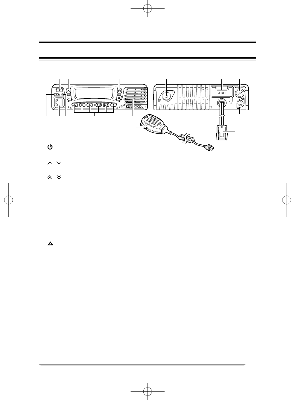
GETTING ACQUAINTED
① (Power) switch
Press to switch the transceiver ON or OFF.
② / keys
Press to activate their programmable functions {page 5}.
③ / keys
Press to activate their programmable functions {page 5}.
④ TX/RX Indicator
Lights red while transmitting and green while receiving a signal. Flashes orange when
receiving an optional signaling call.
⑤ Microphone jack
Insert the microphone plug into this jack.
⑥ Status Indicator
Lights blue during a specified mode, based on dealer programming.
⑦ / S / A / <B / C> / ■ keys
Press to activate their programmable functions {page 5}.
⑧ Speaker
Internal speaker.
⑨ PTT switch
Press this switch, then speak into the microphone to call a station.
⑩ RF antenna connector
Connect the RF antenna to this connector.
⑪ ACC connector
Connect the ACC to this connector, via the KCT-60.
⑫ External speaker jack
Connect an external speaker to this jack.
⑬ GPS antenna connector <GPS model olny>
Connect the KRA-40 GPS antenna to this connector.
⑭ Power input connector
Connect the DC Power Cable to this connector.
;=B > 2
8
:@.
⑭
4
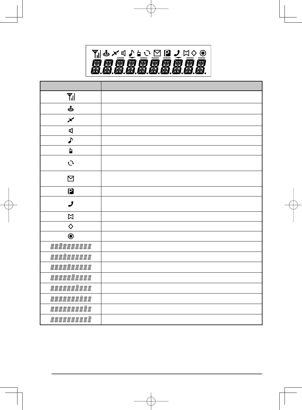
DISPLAY
Icon Description
Displays the signal strength.
Not used.
Appears when the GPS position is determined.
Appears when the Monitor or Squelch Off is activated.
Blinks when an incoming call matches your Optional Signaling.
Appears when the Talk Around function is on.
Lights while scanning or while paused on a channel. Blinks
when scan is temporarily stopped.
Lights when a caller message is in the stack memory. Blinks
when the new message is in the stack memory.
The selected channel is the Priority channel.
Appears when the selected group is programmed as telephone
IDs. Blinks during Auto Telephone search.
The Horn Alert function is on.
The Scrambler function is on.
The Public Address function is on.
Not used.
The current zone is added to the scan sequence.
The External Speaker function is on.
The AUX A function is on.
The AUX B function is on.
The current Channel/Group ID is added to the scan sequence.
The Operator Selectable Tone function is on.
Not used.

5
PROGRAMMABLE FUNCTIONS
The , , , , , S, A, <B, C>, and ■ keys can be programmed with the functions
listed below. Ask your dealer for details on these functions.
• None
• 2-tone
1, 7
• Autodial
1
• Autodial Programming
1
• Auto Telephone
1
• AUX A
• AUX B
• Broadcast
2
• Call 1 ~ 6
• CH/GID Down
• CH/GID Recall
• CH/GID Up
• Channel Entry
1
• CW Message
3
• Direct CH/GID 1 ~ 5
• Display Format
1
• Emergency
4
• Fixed Volume
• Forced Search
2
• Function
• GPS Position Display
• Group
1, 2
• Group + Short Message 1, 5
• Group + Status 1, 5
• Home CH/GID
• Horn Alert
• Individual
5
• Individual + Short Message 5
• Individual + Status
5
• LCD Brightness
• Lone Worker
• Low Transmit Power
• Maintenance
• Monitor
6
• Monitor Momentary
6
• Operator Selectable Tone (OST) 7
• Priority-channel Select
8
• Public Address
• Scan
• Scan Delete/Add
• Scrambler/ Encryption
• Selcall
9
• Selcall + Short Message 9
• Selcall + Status 9
• Send the GPS data
• Short Message
1
• Site Down
2
• Site Lock
2
• Site Up
2
• Squelch Level
7
• Squelch Off
7
• Squelch Off Momentary 7
• Stack
• Status
• Talk Around
5
• Telephone Disconnect
1
• Transceiver Password
• Zone Delete/Add
• Zone Down
• Zone Select
4
• Zone Up

6
1 Available only for Analog Trunking operation.
2 Available only for NXDN Trunking operation.
3 Available only for NXDN Conventional operation.
4 Emergency can be programmed only on the key. When assigned, the dealer must
set the key assignment hold to “Enable” and second function as “Emergency”.
5 Available only for NXDN Conventional operation and NXDN Trunking operation.
6 Available only for Analog Conventional, Analog Trunking, and NXDN Conventional
operation.
7 Available only for Analog Conventional operation.
8 Available only for Analog Conventional and NXDN Conventional operation.
9 Available only for Analog Conventional and Analog Trunking operation.
BASIC OPERATIONS
SWITCHING POWER ON/ OFF
Press to switch the transceiver ON.
• A beep sounds and the display illuminates.
• If the Transceiver Password function is programmed, “PASSWORD” will appear on the
display.
Press again to switch the transceiver OFF.
■ Transceiver Password
To enter the password:
1 Press the / key to select a digit.
• When using a keypad, simply enter the password digits and proceed to step 4.
2 Press the S or key to accept the entry and move to the next digit.
• Press the A or # key to delete an incorrect digit.
• Press the C> key to delete all.
3 Repeat steps 1 and 2 to enter the entire password.
• The password can contain a maximum of 6 digits.
4 Press the S or key to confirm the entered password.
• If you enter an incorrect password, an error tone sounds and the transceiver
remains locked.
ADJUSTING THE VOLUME
Press the [Volume Up] key to increase the volume. Press the [Volume Down] key to
decrease the volume.
If Squelch Off has been programmed onto a key, you can use that function to listen to
background noise while adjusting the volume level.

7
SELECTING A ZONE AND CHANNEL/GROUP ID
Select the desired zone and channel/group ID using the keys programmed as [Zone Up]/
[Zone Down] and [CH/GID Up]/ [CH/GID Down].
• You can program names for zones and channels/group IDs with up to 10 characters.
TRANSMITTING/ RECEIVING
1 Select the desired zone and channel/group ID.
2 Press the key programmed as [Monitor] or [Squelch Off] to check whether or not the
channel is free.
• If the channel is busy, wait until it becomes free.
3 Press the PTT switch and speak into the microphone. Release the PTT switch to
receive.
• For best sound quality, hold the transceiver approximately 1.5 inches (3 ~ 4 cm)
from your mouth.
■ Making Group Calls (Digital)
If a key has been programmed as [Group], you can select a group ID from the list to
make a call to those parties on a Conventional channel.
To select a group ID:
1 Press the key programmed as [Group].
2 Press the / key to select a group ID/name from the list.
3 Press and hold the PTT switch to make the call.
• Speak into the transceiver as you would during a normal transmission.
■ Making Individual Calls (Digital) (Types I and II Only)
If a key has been programmed with [Individual], you can make calls to specific
persons.
1 Press the key programmed as [Individual].
2 Press the / key to select a unit ID from the list.
• On Type I models, you can enter a unit ID directly.
3 Press and hold the PTT switch to make the call.
• Speak into the transceiver as you would during a normal transmission.

8
RECEIVING
Select the desired zone and channel. If signaling has been programmed on the selected
channel, you will hear a call only if the received signal matches your transceiver settings.
Note: Signaling allows your transceiver to code your calls. This will prevent you from listening to
unwanted calls. Refer to “SIGNALING” on page XX for details.
■ Receiving Group Calls (Digital)
When you receive a group call on a Conventional channel and the received group ID
matches the ID set up on your transceiver, you can hear the caller’s voice.
When you receive a group call on a Trunking channel, the transceiver automatically
switches to the communications channel to receive the call.
■ Receiving Individual Calls (Digital)
When you receive an individual call, a ringing tone will sound and the caller’s ID will
appear on the display (types I and II only). To respond to the call, press and hold the
PTT switch and speak into the transceiver as you would during a normal transmission.
SCAN
Scan monitors for signals on the transceiver channels. While scanning, the transceiver
checks for a signal on each channel and only stops if a signal is present.
To begin scanning, press the key programmed as [Scan].
• The indicator appears.
• When a signal is detected on a channel, Scan pauses at that channel. The transceiver
will remain on the busy channel until the signal is no longer present, at which time Scan
resumes.
To stop scanning, press the [Scan] key again.
Note: To use Scan, there must be at least 2 channels in the scan sequence.
TEMPORARY CHANNEL LOCKOUT
During scan, you can temporarily remove specific channels from the scanning sequence by
selecting them and pressing the key programmed as [Scan Delete/Add].
• The channel is no longer scanned. However, when scanning is ended and restarted,
the channels are reset and deleted channels will again be in the scanning sequence.
PRIORITY SCAN
If a Priority channel has been programmed, the transceiver will automatically change to the
Priority channel when a call is received on that channel, even if a call is being received on
a normal channel.
• The indicator appears when the selected channel is the Priority channel (depending
on dealer setting).

9
SCAN REVERT
The Scan Revert channel is the channel selected when you press the PTT switch to
transmit during scan. Your dealer can program one of the following types of Scan Revert
channels:
• Selected: The last channel selected before scan.
• Selected + Talkback: Same as “Selected”, plus you can respond to calls on the
channel at which scan is paused.
• Priority: The Priority channel.
• Priority + Talkback: Same as “Priority”, plus you can respond to calls on the channel
at which scan is paused.
• Last Called + Selected: The last channel on which you receive a call.
SCAN DELETE/ADD
You can add and remove zones and/or channels/group IDs to and from your scan list.
1 Select your desired zone and/or channel/group ID.
2 Press the key programmed as [Zone Delete/Add] (to add/remove zones) or [Scan
Delete/Add] (to add/remove channels/group IDs).
• You can also press and hold the key programmed as [Scan Delete/Add] to add/
remove zones.
• When a channel/Group ID is added to scan, the icon appears on
the display.
• When a zone is added to scan, the icon appears on the display.

10
FleetSync: ALPHANUMERIC 2-WAY PAGING FUNCTION
FleetSync is an Alphanumeric 2-way Paging Function, and is a protocol owned by
JVC KENWOOD Corporation.
Note: This function is available only in analog operation.
SELCALL (SELECTIVE CALLING)
A Selcall is a voice call to a station or group of stations.
■ Transmitting
1 Select your desired zone and channel.
2 Press the key programmed as [Selcall] to enter Selcall mode.
3 Press the / key to select the station you want to call.
4 Press the PTT switch and begin your conversation.
■ Receiving
An alert tone will sound and the transceiver will enter Selcall mode. The calling
station’s ID will appear when a Selcall is received (types I and II only). You can
respond to the call by pressing the PTT switch and speaking into the microphone.
■ Identifi cation Codes
An ID code is a combination of a 3-digit Fleet number and a 4-digit ID number. Each
transceiver has its own ID.
• Enter a Fleet number (100 ~ 349) to make a group call.
• Enter an ID number (1000 ~ 4999) to make an individual call in your fleet.
• Enter a Fleet number to make a call to all units in the selected fleet (Fleet call).
STATUS MESSAGE
You can send and receive 2-digit Status messages which may be decided in your talk
group. Messages can contain up to 16 alphanumeric characters. Status messages range
from 10 to 99 (80 ~ 99 are reserved for special messages).
A maximum of 15 received messages (combined status messages and short messages)
can be stored in the stack memory of your transceiver.
■ Transmitting
1 Select your desired zone and channel.
2 Press the key programmed as [Status] to enter Status mode (proceed to step 5) or
[Selcall + Status] to enter Selcall mode (proceed to step 3).
3 Press the / key to select the station you want to call.
• If Manual Dialing is enabled, you can enter a station ID by using the DTMF
keypad by pressing and hold the S or key. Repeat this process until the
entire ID is entered.

11
4 Press the S or key to enter Status mode.
5 Press the / key to select the status you want to transmit.
• If Manual Dialing is enabled, you can enter a station ID by using the DTMF
keypad. (refer to step 3, above).
6 Press the PTT switch or Side 2 key to initiate the call.
• “COMPLETE” appears on the display when the status has been successfully
transmitted.
■ Receiving
A calling ID or text message will appear when a Status call is received. Press any key
to return to normal operation.
■ Reviewing Messages in the Stack Memory
1 Press the key programmed as [Stack], or press and hold the key programmed as
[Selcall], [Status], or [Selcall + Status] to enter Stack mode.
• The last received message is displayed.
2 Press the / key to select the desired message.
• Message types are identified as follows:
ID: Caller ID, ST: Status Message, ME: Short Message
• Press and hold the S key for 1 second to cycle the display information as
follows:
ID Name > Status/Short Message > CH/GID
3 Press the Side 1 key to return to normal operation.
• To delete the selected message, press the A key. To confirm the deletion,
Press the S key.
• To delete all messages, press and hold the A or # key for 1 second. To confirm
the deletion, Press the S or key.
SHORT MESSAGES
This transceiver can receive short data messages which contain a maximum of 48
characters.
• Received short messages are displayed the same as Status messages. A maximum of
15 received messages (combined status messages and short messages) can be stored
in the stack memory of your transceiver.
GPS REPORT
To send your location data, you must first connect a GPS unit to the transceiver. GPS data
can be manually transmitted by pressing the key programmed as [Send the GPS data]. If
set up by your dealer, GPS data may be automatically transmitted at a preset time interval.

12
TRUNKING CALLS (ANALOG)
PLACING A DISPATCH CALL
1 Select the desired zone and channel/group ID.
2 Press and hold the PTT switch.
3 If the “PTT Proceed” tone sounds, communication is possible; start speaking into the
microphone. Release the PTT switch to receive.
• For best sound quality at the receiving station, hold the microphone approximately
1.5 inches (3 ~ 4 cm) from your mouth.
• Your dealer can deactivate the Proceed PTT tone, if necessary. Ask your dealer for
details.
RECEIVING A DISPATCH CALL
1 When a dispatch call is received, the transceiver will automatically change to the
correct group ID and you will hear the call.
2 Readjust the volume as necessary.
PLACING A TELEPHONE CALL
1 Select the desired zone and channel/group ID.
2 Press and hold the PTT switch for approximately 1 second to ensure a connection.
• Confirm that there is a dial tone after releasing the PTT switch.
3 Alternatively, press the key programmed as [Auto Telephone] to automatically search
for a Telephone Repeater.
• “AUTO TEL” appears on the display and the icon blinks.
• When the transceiver connects to a telephone line, a dial tone sounds, the icon
appears on the display, and the transceiver enters the Off Hook state.
4 Place the call, following the instructions for making a DTMF call, starting on page 9.
5 When the called party responds, press the PTT switch and speak into the microphone.
Release the PTT switch to receive.
• Only one person can speak at a time.
RECEIVING A TELEPHONE CALL
1 When a telephone call is received, the transceiver will automatically change to the
correct group ID and you will hear the call.
• A ringer tone will sound when a call is received.
2 Press and hold the PTT switch to speak, and release it to receive.
• Only one person can speak at a time.
DISCONNECT WITH TELEPHONE
To end the call, press the # key or the key programmed as [Telephone Disconnect] while
communicating.

13
ADVANCED OPERATIONS
DTMF (DUAL TONE MULTI FREQUENCY) CALLS
■ Making a DTMF Call
Manual Dialing
1 Press and hold the PTT switch.
2 Enter the desired digits using the DTMF keypad.
• If you release the PTT switch, transmit mode will end even if the complete
number has not been sent.
• If the Keypad Auto PTT function has been enabled by your dealer, you do
not need to press the PTT switch to transmit; you can make the call simply by
pressing the DTMF keys.
Store & Send
1 Press the key programmed as [Autodial].
2 Enter up to 30 digits using the DTMF keypad.
• Alternatively, you can enter digits by using the Selector.
3 Press the PTT switch to make the call.
■ Autodial
Autodial allows you to quickly call DTMF numbers that have been programmed onto
your transceiver.
1 Press the key programmed as [Autodial].
• The first entry in the Autodial list appears on the display.
2 Press the / key to select your desired Autodial list number, or enter the list
number directly (01 ~ 32).
• The stored entry appears on the display.
3 Press the PTT switch to make the call.
■ Stun Code
This function is used when a transceiver is stolen or lost. When the transceiver
receives a call containing a stun code, the transceiver becomes disabled. The stun
code is cancelled when the transceiver receives a call with a revive code.

14
EMERGENCY CALLS
If your transceiver has been programmed with the Emergency function, you can make
emergency calls.
1 Press and hold the key programmed as [Emergency].
• Ask your dealer for the length of time necessary to hold this key before the
transceiver enters Emergency mode.
• When the transceiver enters Emergency mode, it will change to the Emergency
channel and begin transmitting based on how it is set up by your dealer.
2 To exit Emergency mode, press the [Emergency] key again.
• If the Emergency mode completes a preset number of cycles, Emergency mode will
automatically end and the transceiver will return to the zone and channel that was in
use before Emergency mode was entered.
Note:
◆ Your dealer can set the transceiver to emit a tone when transmitting in Emergency mode.
◆ Your dealer can set the transceiver to emit tones and received signals as normal, or mute the
speaker during Emergency operation.
SCRAMBLER
Press the key programmed as [Scrambler/ Encryption], to switch the transceiver to
secure (encrypted) transmission.
• Pressing the PTT switch after the Scrambler function has been turned ON encrypts the
transmitted signal.
SIGNALING
■ Quiet Talk (QT)/ Digital Quiet Talk (DQT)
Your dealer may have programmed QT or DQT signaling on your transceiver channels.
A QT tone/ DQT code is a sub-audible tone/code which allows you to ignore (not hear)
calls from other parties who are using the same channel.
Operator Selectable Tone
If a key has been programmed with [OST], you can reprogram the QT/DQT settings on
each of your channels.
1 Select your desired channel.
2 Press and hold the key programmed as [OST] for 1 second.
3 Press the / key to select your desired tone or code.
• Your dealer can set up to 40 tones/codes.
4 When you have finished operating using OST, press the [OST] key again to turn the
OST function OFF.

15
■ Radio Access Number (RAN)
RAN is a new signaling system designed for digital radio communications.
When a channel is set up with a RAN, squelch will only open when a call containing
a matching RAN is received. If a call containing a different RAN is made on the same
channel you are using, you will not hear the call. This allows you to ignore (not hear)
calls from other parties who are using the same channel.
■ Optional Signaling
Your dealer may also program several types of optional signaling for your transceiver
channels.
2-tone Signaling: 2-tone Signaling opens the squelch only when your transceiver
receives a call containing matching 2 tones.
DTMF Signaling: DTMF Signaling opens the squelch only when the transceiver
receives a call containing a matching DTMF code.
FleetSync Signaling: Refer to “SELCALL (SELECTIVE CALLING)” on page XX.
NXDN ID Signaling: NXDN ID is an optional signaling system available only for digital
communications.
MONITOR/ SQUELCH OFF
You can use the key programmed as [Monitor] or [Squelch Off] to listen to weak signals
that you cannot hear during normal operation and to adjust the volume when no signals are
present on your selected channel.
• The
icon appears on the display while Monitor or Squelch Off is activated.
Your dealer can program a key with one of four Monitor/Squelch Off functions:
• Monitor: Press to deactivate QT, DQT, DTMF, 2-tone, or FleetSync Signaling. Press
again to return to normal operation.
• Monitor Momentary: Press and hold to deactivate QT, DQT, DTMF, 2-tone or
FleetSync Signaling. Release to return to normal operation.
• Squelch Off: Press to hear background noise. Press again to return to normal
operation.
• Squelch Off Momentary: Press and hold to hear background noise. Release to
return to normal operation.
■ Squelch Level
If a key has been programmed as [Squelch Level], you can readjust your transceiver’s
squelch level:
1 Press the key programmed as [Squelch Level].
• The
icon appears on the display, along with the current squelch level.
2 Press the / key to select your desired squelch level from 0 to 9.
3 Press the C> key to store the new setting.
16
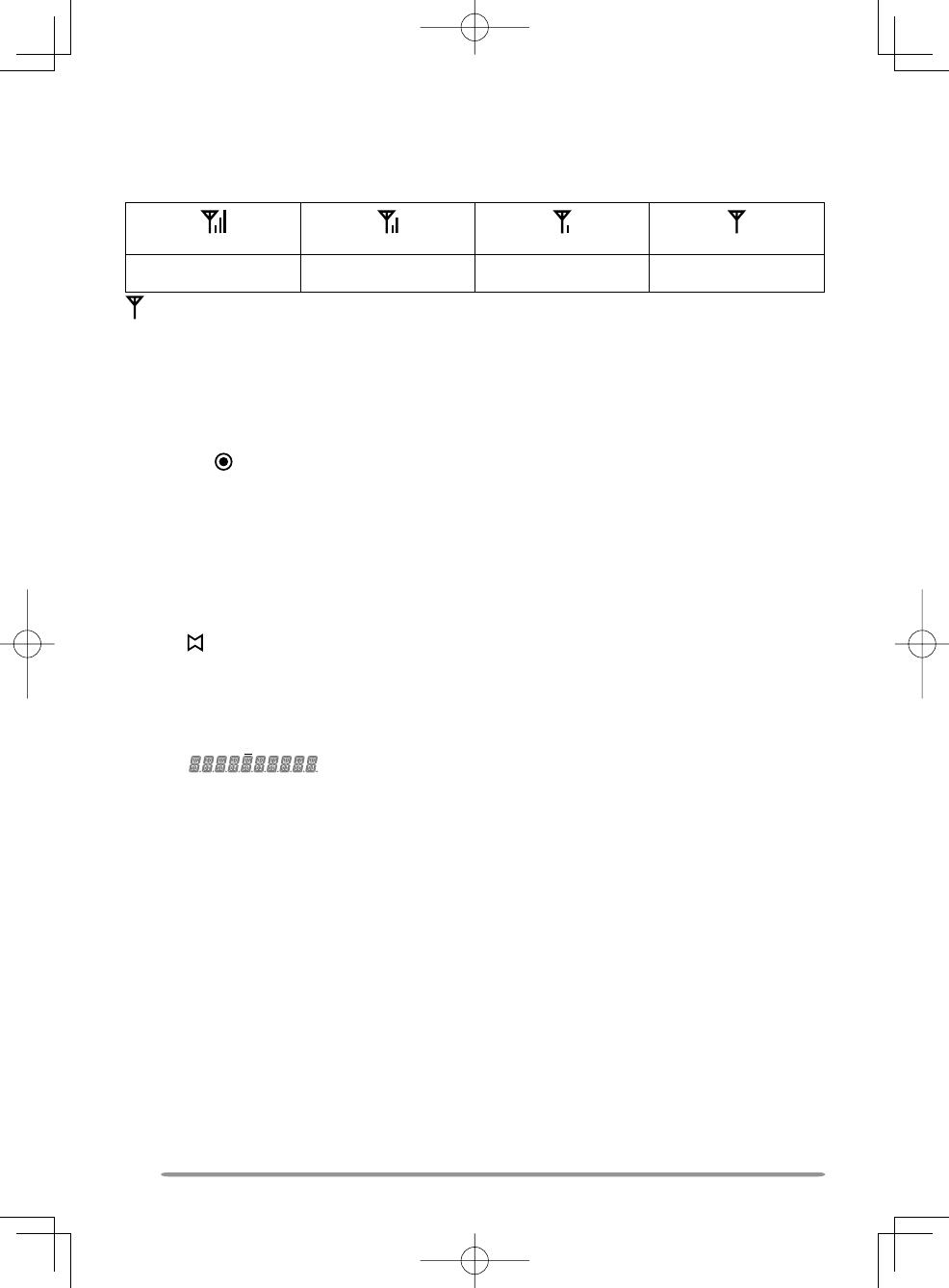
SIGNAL STRENGTH INDICATOR
The signal strength indicator displays the strength of received calls. No icon appears when
no signal is available.
Strong Sufficient Weak Very weak
flashes when out of range (NXDN Trunking only).
PUBLIC ADDRESS (PA)
The PA system can only be used with an external speaker.
1 Press the key programmed as [Public Address] to activate the Public Address
function.
• The icon appears on the display.
2 Press and hold the PTT switch, then speak into the microphone to make your address
through the external speaker.
3 Press the [Public Address] key again to exit Public Address.
HORN ALERT
Press the key programmed as [Horn Alert] to toggle the Horn Alert function ON or OFF.
• The icon appears on the display while Horn Alert is activated.
EXTERNAL SPEAKER
After attaching an external speaker to the transceiver, p
ress the key programmed as
[External Speaker] to output all received signals through the external speaker.
• The icon appears on the display.
Press the [External Speaker] key again to output all received signals only through the
built-in speaker.
DISPLAY BRIGHTNESS
You can cycle the display brightness between high, low, and off by pressing the key
programmed as [LCD Brightness].

17
BACKGROUND OPERATIONS
TIME-OUT TIMER (TOT)
The Time-out Timer prevents you from using a channel for an extended duration. If you
continuously transmit for a preset time, the transceiver will stop transmitting and an alert
tone will sound. Release the PTT switch.
AUXILIARY PORT
Press the key programmed as [AUX A] or [AUX B] to activate the auxiliary port. The
auxiliary port is used with optional boards.
• The icon appears on the display when the auxiliary A port is active.
• The icon appears on the display when the auxiliary B port is active.
BUSY CHANNEL LOCKOUT (BCL)
If BCL is set up by your dealer, you will be unable to transmit if the channel is already in
use.
• “BUSY” appears on the display when you press the PTT switch. Use a different
channel or wait until the channel becomes free.
If your dealer has programmed BCL Override for your transceiver, you can override the
BCL by pressing the PTT switch again, immediately after releasing it, when the channel is
busy.
CONTROL CHANNEL HUNT
On digital Trunking channels, the transceiver automatically searches for a control channel.
• While searching for a control channel, the antenna icon will flash (types I and II only)
and no signals can be received.
PTT ID
PTT ID is the transceiver unique ID code which is sent each time the PTT switch is pressed
and/or released.
COMPANDER
If programmed by your dealer for a channel, the compander will remove excessive noise
from transmitted signals, providing higher clarity of signals.
TRANSMIT POWER
Your dealer has programmed a transmit power level for each channel. Power levels can
be high, medium, or low.

MANDATORY SAFETY INSTRUCTIONS TO INSTALLERS AND USERS
• Use only manufacturer or dealer supplied antennas.
• Antenna Minimum Safe Distance: 40 cm (16 inches), 50% duty Cycle.
• Antenna Gain: 0 dBd referenced to a dipole.
The Federal Communications Commission has adopted a safety standard
for human exposure to RF (Radio Frequency) energy which is below the
OSHA (Occupational Safety and Health Act) limits.
•
Antenna Mounting: The antenna supplied by the manufacturer or radio
dealer must not be mounted at a location such that during radio transmission,
any person or persons can come closer than the above indicated minimum
safe distance to the antenna, i.e. 40 cm (16 inches) , 50% duty Cycle.
• To comply with current FCC RF Exposure limits, the antenna must
be installed at or exceeding the minimum safe distance shown
above, and in accordance with the requirements of the antenna
manufacturer or supplier.
•
Vehicle installation: The antenna can be mounted at the center of a
vehicle metal roof or trunk lid, if the minimum safe distance is observed.
• Base Station Installation: The antenna should be fixed-mounted on
an outdoor permanent structure. RF Exposure compliance must be
addressed at the time of installation.
Antenna substitution: Do not substitute any antenna for the one supplied
or recommended by the manufacturer or radio dealer.
You may be exposing person or persons to excess radio frequency radiation.
You may contact your radio dealer or the manufacturer for further instructions.
Maintain a separation distance from the antenna to person(s) of
at least 40 cm (16 inches), 50% duty Cycle.
“This transmitter is authorized to operate with a maximum duty factor of 50%, in
typical push-to-talk mode, for satisfying FCC RF exposure compliance requirements.”
You, as the qualified end-user of this radio device must control the exposure
conditions of bystanders to ensure the minimum separation distance (above) is
maintained between the antenna and nearby persons for satisfying RF Exposure
compliance. The operation of this transmitter must satisfy the requirements of
Occupational/Controlled Exposure Environment, for work-related use, transmit
only when person(s) are at least the minimum distance from the properly installed,
externally mounted antenna. Transmit only when people outside the vehicle are at
least the recommended minimum lateral distance away from the antenna/vehicle.
B59-2723-00