JVCKENWOOD 474701 900 MHz Digital Base Repeater User Manual NXR 5700 NXR 5800 NXR 5900 NXR 5901
JVC KENWOOD Corporation 900 MHz Digital Base Repeater NXR 5700 NXR 5800 NXR 5900 NXR 5901
Contents
- 1. Instruction Manual
- 2. Product Safety Manual
Instruction Manual

B5A-2265-00 (K)
NXR-5700
NXR-5800
NXR-5900
NXR-5901
VHF DIGITAL BASE-REPEATER
UHF DIGITAL BASE-REPEATER
800MHz DIGITAL BASE-REPEATER
900MHz DIGITAL BASE-REPEATER
INSTRUCTION MANUAL
BASE-RELAIS NUMÉRIQUE VHF
BASE-RELAIS NUMÉRIQUE UHF
BASE-RELAIS NUMÉRIQUE 800MHz
BASE-RELAIS NUMÉRIQUE 900MHz
MODE D’EMPLOI
BASE-REPETIDOR DIGITAL VHF
BASE-REPETIDOR DIGITAL UHF
BASE-REPETIDOR DIGITAL 800MHz
BASE-REPETIDOR DIGITAL 900MHz
MANUAL DE INSTRUCCIONES
NXR-5800
1
◆ This repeater is intended for use as a fixed base station
with the antenna located outdoors on the rooftop or on an
antenna tower.
◆ This repeater is designed for a 13.6 V DC (NXR-5700/ NXR-
5800) or 13.8 V DC (NXR-5900/ NXR-5901) DC power
source. Never use a 24 V DC or higher source to power the
repeater.
◆ Use only the supplied DC cord.
◆ Do not remove the ferrite core attached to the DC cord.
Doing so may cause interference with radio communications.
◆ Do not put anything on top of the repeater. This will obstruct
heat dissipation.
UNPACKING AND CHECKING EQUIPMENT
Note: The following unpacking information is for use by your KENWOOD
dealer, an authorized KENWOOD service center, or the factory.
Carefully unpack the repeater. We recommend that you identify
the items listed in the following table before discarding the
packing material. If any items are missing or have been damaged
during shipment, file a claim with the carrier immediately.
Item Part Number Quantity
Front glass B10-2781-XX 1
Dressed screw N08-0563-XX 1
Bracket J29-0725-XX 2
Flat head machine screw N32-4008-XX 4
Handle K01-0421-XX 1
DC cord E30-3427-XX 1
Lead wire with connector (15 pin) E31-3228-XX 1
Fuse (15 A) : NXR-5700/ NXR-5800 F52-0042-XX 1
Fuse (7.5A) : NXR-5900/ NXR-5901 FZB10AX-7R5 1
SYNC cable E3A-0177-XX 1
Instruction manual B5A-2265-XX 1
INSTALLATION
To install the handles onto the front panel of the repeater, align
the handles with the holes on the front panel, then secure the
handles using the supplied screws.
Consult your dealer for installing the repeater and antenna.
MICROPHONE
Connect an optional KMC-30, KMC-35, KMC-9C, or KMC-53
KENWOOD microphone to the MICROPHONE jack on the front
panel.
OCXO UNIT (KXK-3):Option
The OCXO unit (KXK-3) is an Oven Controlled Crystal Oscillator
unit.
NOTICES TO THE USER
◆ Government law prohibits the operation of unlicensed radio
transmitters within the territories under government control.
◆ Illegal operation is punishable by fine and/or imprisonment.
◆ Refer service to qualified technicians only.
One or more of the following statements may be applicable:
FCC WARNING
This equipment generates or uses radio frequency energy. Changes
or modifications to this equipment may cause harmful interference
unless the modifications are expressly approved by the party
responsible/JVCKENWOOD. The user could lose the authority to
operate this equipment if an unauthorized change or modification is
made.
INFORMATION TO THE DIGITAL DEVICE USER REQUIRED BY
THE FCC
This equipment has been tested and found to comply with the limits
for a Class B digital device, pursuant to Part 15 of the FCC Rules.
These limits are designed to provide reasonable protection against
harmful interference in a residential installation.
This equipment generates, uses and can generate radio frequency
energy and, if not installed and used in accordance with the
instructions, may cause harmful interference to radio communications.
However, there is no guarantee that the interference will not occur
in a particular installation. If this equipment does cause harmful
interference to radio or television reception, which can be determined
by turning the equipment off and on, the user is encouraged to try to
correct the interference by one or more of the following measures:
• Reorient or relocate the receiving antenna.
• Increase the separation between the equipment and receiver.
• Connect the equipment to an outlet on a circuit different from that to
which the receiver is connected.
• Consult the dealer for technical assistance.
THANK YOU!
We are grateful you purchased this KENWOOD repeater.
PRECAUTIONS
• Donotexposetherepeatertorainormoisture;topreventre
or electric shock.
• Donotopentherepeater.underanycircumstances;toavoid
risk of electric shock.
• Donotexposetherepeatertoextremelyhotorcold
conditions.
• Donotexposetherepeatertolongperiodsofdirectsunlight,
nor place it close to heating appliances.
• Donotplacetherepeaterinexcessivelydustyand/orhumid
areas, nor on unstable surfaces.
• Donotputtheplasticbagusedforpackingofthisequipment
on the place which reaches a small child's hand. It will
become a cause of suffocation if it wears flatly.
• DonotuseoptionsnotspeciedbyKENWOOD.
• Installoptionalaccessorieswhenpowerisnotappliedtothe
repeater.
• Ifyoudetectanabnormalodororsmokecomingfromthe
repeater, disconnect the power from the repeater immediately.
Contact your KENWOOD service center or dealer.
NXR-5700/ NXR-5800/ NXR-5900/ NXR-5901 INSTRUCTION MANUAL
VHF DIGITAL BASE-REPEATER / UHF DIGITAL BASE-REPEATER / 800MHz DIGITAL BASE-REPEATER / 900MHz DIGITAL BASE-REPEATER
Firmware Copyrights
The title to and ownership of copyrights for firmware embedded in
KENWOOD product memories are reserved for JVC KENWOOD
Corporation.
The AMBE+2
TM
voice coding Technology embodied in this product
is protected by intellectual property rights including patent rights,
copyrights and trade secrets of Digital Voice Systems, Inc. This
voice coding Technology is licensed solely for use within this
Communications Equipment. The user of this Technology is explicitly
prohibited from attempting to extract, remove, decompile, reverse
engineer, or disassemble the Object Code, or in any other way
convert the Object Code into a human-readable form. U.S. Patent
Nos. #8,315,860, #8,595,002, #6,199,037, #6,912,495, #8,200,497,
#7,970,606, and #8,359,197.
◆ Do not install the repeater in explosive atmospheres
(inflammable gas, dust particles, metallic powders, grain
powders, etc.).
2
REPEATER OPERATION
Note: Please consult your dealer for programming the repeater.
Due to the frequency stability on the 6.25 kHz bandwidth channel, when
operating the repeater using an optional OCXO unit, allow the unit to
warm up after turning the power on. Refer to the KXK-3 instruction
manual concerning the warm up duration.
After turning on the power, wait for approximately 10 seconds for the
VCXO or 5 minutes for the OCXO (when mounting) to warm up. During
this time, the CH/STATUS Display will blink. The keys will function when
they are pressed.
When power is applied to the repeater, the POWER indicator
lights green. Turn the VOLUME control clockwise until a click
sounds, to unmute the audio. Rotate to adjust the audio. Turn the
VOLUME control counterclockwise fully to mute the audio.
The BUSY indicator lights green while receiving a signal and the
TX indicator lights red while transmitting.
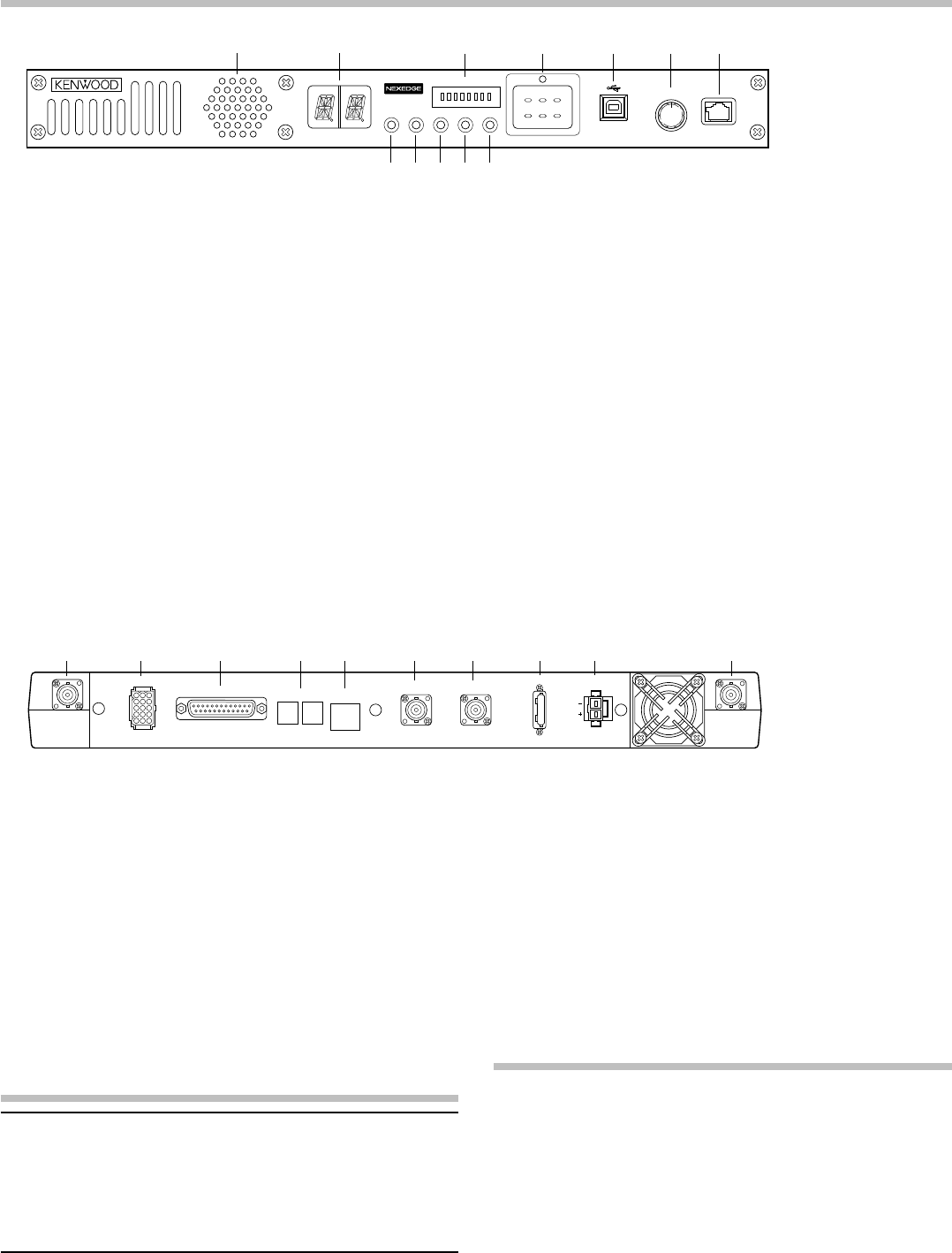
■ Rear Panel
a RX IN jack
Connect an RX antenna or a duplexer to this BNC
receptacle.
b TEST/SPKR jack
Test input/output jack. Connect an external speaker to this
jack. When using a Built-in speaker, connect the attached
Lead wire with connector (15 pin) to this jack.
c CONTROL I/O jack
Connect a repeater controller or a remote panel to this
DB-25 interface.
d SYNC 1 / 2 jack
Connect to another repeater to use synchronous frame
signaling for digital trunking.
e LAN jack
Connect to Ethernet. Use a shielded category 5e or higher
standard LAN cable shorter than 3 meters.
CONTROLS AND FUNCTIONS
■ Front Panel
f REF OUT jack
Connect to another repeater within the site to supply a
reference signal.
g REF IN jack
Connect from another repeater within the site to receive a
reference signal.
h FUSE
Insert 15 A (NXR-5700/ NXR-5800)/ 7.5 A (NXR-5900/
NXR-5901) blade fuse into this fuse holder.
i DC 13.6V jack/ DC 13.8V jack
Connect a 13.6 V DC (NXR-5700/ NXR-5800)/ 13.8 V DC
(NXR-5900/ NXR-5901)power supply to this jack.
j TX OUT jack
Connect a TX antenna or a duplexer to this BNC receptacle.
TRANSCEIVER OPERATION
■ Receive
Adjust the volume to your desired level. You may need to
readjust the volume if you are having interference while
receiving a message from your dispatcher or another member
in your fleet.
The BUSY indicator lights green while a signal is being
received.
■ Transmit
1 Listen to the channel before transmitting, to make sure it
is not being used.
2 Press the microphone PTT switch, then speak in your
normal speaking voice.
The TX indicator lights red while transmitting.
3 When you finish speaking, release the PTT switch.
a Speaker
b CH/STATUS display
Two 17-segment digits display the channel number, name,
or status.
c STATUS indicator
Indicates the status of the repeater. (NXDN mode)
d Programmable function keys
Press these keys to activate their programmable functions.
e USB jack (B-Type)
Connect to the PC using a USB cable.
f VOLUME control
Turn clockwise until a click sounds, to unmute the audio.
Rotate to adjust the audio. Turn counterclockwise fully to
mute the audio.
g MICROPHONE jack
Connect a microphone to this 8-pin modular jack.
h POWER indicator
Lights green when power is supplied to the DC 13.6V jack
or DC 13.8V jack. Blinks red when an abnormal voltage is
present. While blinking, the repeater cannot be used.
i TX indicator
Lights red while transmitting.
j BUSY indicator
Lights green while a signal is being received.
k OCXO indicator
The OCXO indicator shows the state of the reference
10 MHz oscillator :
Lights Green when using a reference signal from an
optional OCXO unit (KXK-3).
Lights Orange when using a reference signal from another
repeater. Blinks orange when 50 Ω termination is set to
the repeater while having reference signal from another
repeater.
Lights red when no reference signal is available or when
an error occurs.
Does not light when using an internal VCXO reference
signal.
l CTRL indicator
The CTRL indicator shows the control channel status
while using Digital trunking :
Lights Green when the repeater is used as control channel.
Blinks Green when using a non-dedicated control channel.
a b d e f g
hi
c
MICROPHONE
VOLUME
OFF/
POWERCTRL OCXO BUSY TX
1 2
MON
TAKE
OVER
RPT
DISABLE
A B C
345678
STATUS
jkl
a b d e f gc
TEST/SPKR
RX TX
CONTROL I/O SYNC
1 2
LAN
REF OUT REF IN
FUSE
15
DC 13.6V
h i j
The illustration shows the
NXR-5700/ NXR-5800.
© 2017
MANDATORY SAFETY INSTRUCTIONS TO INSTALLERS AND
USERS
• Useonlymanufacturerordealersuppliedantenna.
• AntennaMinimumSafeDistance: Refer to the values in the table
below.
• AntennaGain:0dBdreferencedtoadipole.
TheFederalCommunicationsCommissionhasadoptedasafetystandard
forhumanexposuretoRF(RadioFrequency)energywhichisbelowthe
OSHA(OccupationalSafetyandHealthAct)limits.
• AntennaMounting:Theantennasuppliedbythemanufactureror
radiodealermustnotbemountedatalocationsuchthatduring
radiotransmission,anypersonorpersonscancomecloserthanthe
minimumsafedistanceindicatedinthetablebelow.
• TocomplywithcurrentFCC/ISEDRFExposurelimits,theantenna
mustbeinstalledatorexceedingtheminimumsafedistanceshown
above,andinaccordancewiththerequirementsoftheantenna
manufacturerorsupplier.
• Vehicleinstallation:Theantennacanbemountedatthecenter
ofavehiclemetalroofortrunklid,iftheminimumsafedistanceis
observed.
• BaseStationInstallation:Theantennashouldbexed-mountedon
anoutdoorpermanentstructure.RFExposurecompliancemustbe
addressedatthetimeofinstallation.
Antennasubstitution:Donotsubstituteanyantennafortheonesupplied
orrecommendedbythemanufacturerorradiodealer.
Youmaybeexposingpersonorpersonstoexcessradiofrequency
radiation.Youmaycontactyourradiodealerorthemanufacturerforfurther
instructions.
Maintainaseparationdistancefromtheantennatoperson(s)ofatleast
thedistanceindicatedinthetablebelow.
You,asthequaliedend-userofthisradiodevicemustcontrolthe
exposureconditionsofbystanderstoensuretheminimumseparation
distance(tablebelow)ismaintainedbetweentheantennaandnearby
personsforsatisfyingRFExposurecompliance.Theoperationofthis
transmittermustsatisfytherequirementsofOccupational/Controlled
ExposureEnvironment,forwork-relateduse,transmitonlywhenperson(s)
areatleasttheminimumdistancefromtheproperlyinstalled,externally
mountedantenna.Transmitonlywhenpeopleoutsidethevehicleareat
leasttherecommendedminimumlateraldistanceawayfromtheantenna/
vehicle.
Antenna Minimum Safe Distance
NXR-5700-K/NXR-5800-K3 180 cm (6 feet)
NXR-5800-K 120 cm (4 feet)
NXR-5900-K/NXR-5901-K 20 cm (8 inches)
TERMINAL DESCRIPTION
AccessthefollowingURLfortheterminaldescription.
http://manual.kenwood.com/les/B5K-0197-00.pdf