JVCKENWOOD 478500 700/800MHz DIGITAL TRANSCEIVER with Bluetooth User Manual B5A 0868 00 Cover indd
JVC KENWOOD Corporation 700/800MHz DIGITAL TRANSCEIVER with Bluetooth B5A 0868 00 Cover indd
Contents
- 1. Users Manual - 1 of 2
- 2. Users Manual - 2 0f 2
- 3. Users Manual
- 4. User Manual
Users Manual - 1 of 2

B5A-0056-10 (K)
USER GUIDE
GUIDE DE L'UTILISATEUR
GUÍA DEL USUARIO
NX-5000 series
The illustration shows the model with an operation panel attached.
L’illustration représente le modèle avec un panneau de commande fi xé.
La ilustración muestra el modelo con un panel de operaciones adjunto.

USER GUIDE
VHF DIGITAL TRANSCEIVER
NX-5700 NX-5700(B)
UHF DIGITAL TRANSCEIVER
NX-5800 NX-5800(B)
700/800MHz DIGITAL TRANSCEIVER
NX-5900 NX-5900(B)
Firmware Copyrights
The title to and ownership of copyrights for firmware embedded in KENWOOD
product memories are reserved for JVC KENWOOD Corporation.
The AMBE+2TM voice coding Technology embodied in this product is protected
by intellectual property rights including patent rights, copyrights and trade
secrets of Digital Voice Systems, Inc. This voice coding Technology is
licensed solely for use within this Communications Equipment. The user of
this Technology is explicitly prohibited from attempting to extract, remove,
decompile, reverse engineer, or disassemble the Object Code, or in any other
way convert the Object Code into a human-readable form. U.S. Patent Nos.
#6,199,037, #6,912,495, #8,200,497, #7,970,606, and #8,359,197
• SDTM and microSDTM are trademarks of SD-3C, LLC in the United States. and/
or other countries.
• The Bluetooth® word mark and logos are registered trademarks owned
by Bluetooth SIG, Inc. and any use of such marks by JVC KENWOOD
Corporation is under license. Other trademarks and trade names are those of
their respective owners.

2
THANK YOU
We are grateful you have chosen KENWOOD for your Digital Transceiver
applications.
This User Guide covers only the basic operations of your radio. Ask your dealer for
information on anycustomized features they may have added to your radio. For using
details instruction manual, refer to the following URL.
http://manual2.jvckenwood.com/en_contents/search/
CONTENTS
NOTICES TO THE USER ..........................................................................3
PRECAUTIONS ....................................................................................4
TERMINAL DESCRIPTIONS .....................................................................5
UNPACKING AND CHECKING EQUIPMENT ....................................................6
SUPPLIED ACCESSORIES ......................................................................................... 6
PREPARATION ....................................................................................7
ORIENTATION .....................................................................................9
OPERATION PANEL (ATTACHED PANEL OR KCH-19) ............................................... 9
DISPLAY ................................................................................................................. 10
BASIC OPERATION ............................................................................. 13
SWITCHING POWER ON/ OFF ................................................................................. 13
ADJUSTING THE VOLUME ...................................................................................... 13
SELECTING A ZONE AND CHANNEL ....................................................................... 13
TRANSMITTING ...................................................................................................... 13
RECEIVING .............................................................................................................. 13

3
NOTICES TO THE USER
• Government law prohibits the operation of unlicensed radio transmitters within the territories
under government control.
• Illegal operation is punishable by fi ne and/or imprisonment.
• Refer service to qualifi ed technicians only.
Safety: It is important that the operator is aware of, and understands, hazards
common to the operation of any transceiver.
• EXPLOSIVE ATMOSPHERES (GASES, DUST, FUMES, etc.)
Turn OFF your transceiver while taking on fuel or while parked in gasoline service stations. Do not
carry spare fuel containers in the trunk of your vehicle if your transceiver is mounted in the trunk
area.
• INJURY FROM RADIO FREQUENCY TRANSMISSIONS
Do not operate your transceiver when somebody is either standing near to or touching the antenna,
to avoid the possibility of radio frequency burns or related physical injury.
• DYNAMITE BLASTING CAPS
Operating the transceiver within 500 feet (150 m) of dynamite blasting caps may cause them to
explode. Turn OFF your transceiver when in an area where blasting is in progress, or where “TURN
OFF TWO-WAY RADIO” signs have been posted. If you are transporting blasting caps in your
vehicle, make sure they are carried in a closed metal box with a padded interior. Do not transmit
while the caps are being placed into or removed from the container.
One or more of the following statements may be applicable:
FCC WARNING
This equipment generates or uses radio frequency energy. Changes or modifications to this
equipment may cause harmful interference unless the modifications are expressly approved by the
party responsible/ JVC KENWOOD. The user could lose the authority to operate this equipment if
an unauthorized change or modification is made.
INFORMATION TO THE DIGITAL DEVICE USER REQUIRED BY THE FCC
This equipment has been tested and found to comply with the limits for a Class B digital device,
pursuant to Part 15 of the FCC Rules. These limits are designed to provide reasonable protection
against harmful interference in a residential installation.
This equipment generates, uses and can generate radio frequency energy and, if not installed and
used in accordance with the instructions, may cause harmful interference to radio communications.
However, there is no guarantee that the interference will not occur in a particular installation. If
this equipment does cause harmful interference to radio or television reception, which can be
determined by turning the equipment off and on, the user is encouraged to try to correct the
interference by one or more of the following measures:
• Reorient or relocate the receiving antenna.
• Increase the separation between the equipment and receiver.
• Connect the equipment to an outlet on a circuit different from that to which the receiver is
connected.
• Consult the dealer for technical assistance.
This device complies with Industry Canada licence-exempt RSS standard(s). Operation is subject to the
following two conditions: (1) this device may not cause interference, and (2) this device must accept any
interference, including interference that may cause undesired operation of the device.
Under Industry Canada regulations, this radio transmitter may only operate using an antenna of a type
and maximum (or lesser) gain approved for the transmitter by Industry Canada. To reduce potential
radio interference to other users, the antenna type and its gain should be so chosen that the equivalent
isotropically radiated power (e.i.r.p.) is not more than that necessary for successful communication.
4
PRECAUTIONS
Observe the following precautions to prevent fi re, personal injury, and transceiver
damage.
• Do not attempt to confi gure the transceiver while driving; it is too dangerous.
• Do not disassemble or modify the transceiver for any reason.
• Do not expose the transceiver to long periods of direct sunlight, nor place it near heating
appliances.
• If an abnormal odor or smoke is detected coming from the transceiver, switch the transceiver
power off immediately, and contact your KENWOOD dealer.
• Use of the transceiver while you are driving may be against traffi c laws. Please check and
observe the vehicle regulations in your area.
• Do not use options not specifi ed by KENWOOD.
• Do not put the plastic bag used for packing of this equipment on the place which reaches a small
child's hand. It will become a cause of suffocation if it wears fl atly.
• Do not place the transceiver on unstable surfaces.
• Keep the volume as low as possible to protect your hearing.
• Always switch the transceiver power off before installing optional accessories.
• To dispose of batteries, be sure to comply with the laws and regulations in your country or region.
• The transceiver operates in 12 V negative ground systems only! Check the battery polarity and
voltage of the vehicle before installing the transceiver.
• Use only the supplied DC power cable or a KENWOOD optional DC power cable.
• Do not cut and/or remove the fuse holder on the DC power cable.
• Do not place the microphone cable around your neck while near machinery that may catch the
cable.
For passenger safety, install the transceiver securely using the supplied mounting bracket and
screw set so the transceiver will not break loose in the event of a collision.
5
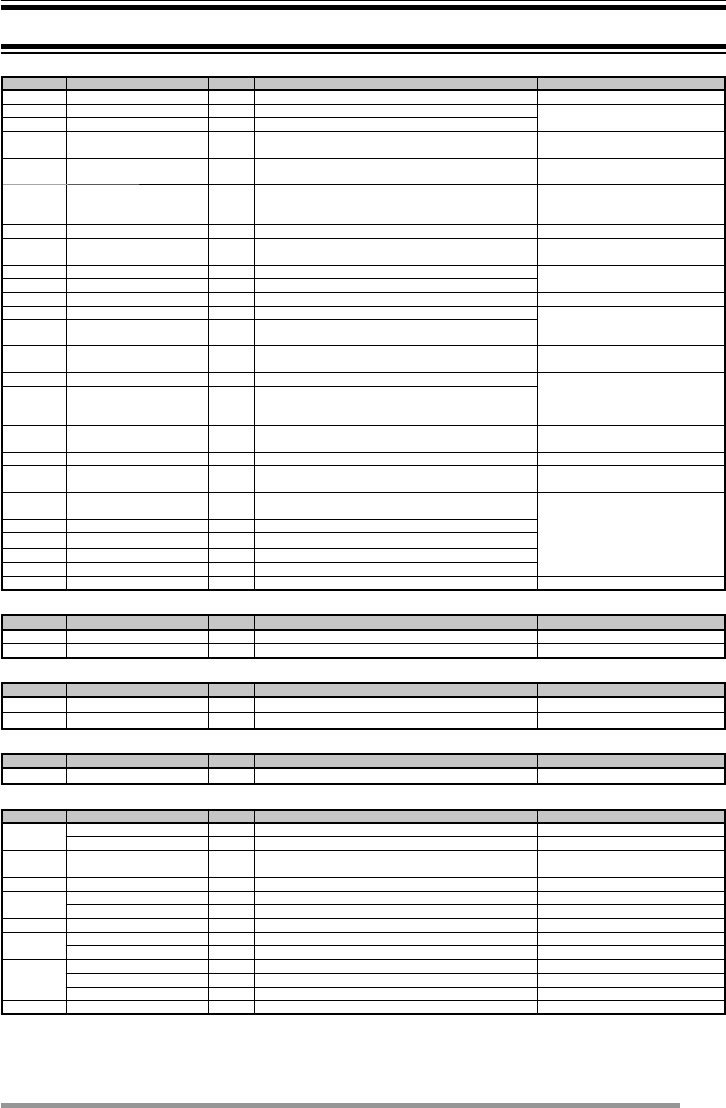
TERMINAL DESCRIPTIONS
ACC (D-SUB 25 Pin Connector)
Pin No. Name I/O Description Specifi cation
1 NC — Not used
2 COM1_RXD I Serial Data Input RS-232C compatible
3 COM1_TXD O Serial Data Output
4 AUXI/O9 I/O Programmable Function I/O 9 Input Impedance 100 k
Output Impedance 100
5 DI I Data Input 0.5 V p-p (Typ.)
Input Impedance 20 k
6 MI2 I MIC Signal Input 5 mVrms(Typ.)
(STD Deviation)
Input Impedance 600
7 GND — Ground Ground
8 AUXI/O8 I/O Programmable Function I/O 8 Input Impedance 100 k
Output Impedance 470
9 COM2_TXD O Serial Data Output TTL (0V - 5V)
10 COM2_RXD I Serial Data Input
11 GND — Ground Ground
12 AUXI/O7/BER_DATA I/O Programmable Function I/O 7 Input Impedance 100 k
Output Impedance 100
13 AUXI/O6/BER_CLK I/O Programmable Function I/O 6
14 SB O DC Power (Switched B) Output 13.6 V ±15%
2 A (Max)
15 AUXO2 O Programmable Function O 2 Open Drain
R (dc): 60 m (Max)
Idc (Max)= -500 mA
16 AUXO1 O Programmable Function O 1
17 AFO O AF Signal Output 0.7 V p-p (Typ.)
Output Impedance 100
18 GND — Ground Ground
19 DEO O RX Detected Signal Output 0.28 Vp-p (Typ.)
Output Impedance 100
20 AUXI/O5 I/O Programmable Function I/O 5
Input Impedance 100 k
Output Impedance 470
21 AUXI/O4 I/O Programmable Function I/O 4
22 AUXI/O3 I/O Programmable Function I/O 3
23 AUXI/O2 I/O Programmable Function I/O 2
24 AUXI/O1 I/O Programmable Function I/O 1
25 ME — Mic Ground Ground
Speaker Jack (3.5 mm Phone Jack) 4 W/ 4
Pin No. Name I/O Description Specifi cation
1 SPO O External Speaker Output 4 (Min)
3 GND — Ground Ground
DC Input Connector
Pin No. Name I/O Description Specifi cation
Red B I DC Power Input 13.6 V ±15%
Black GND — Ground Ground
Ignition Sense Input Terminal
Pin No. Name I/O Description Specifi cation
Yellow B I Ignition Sense Input 13.6 V ±15%
Microphone Jack
Pin No. Name I/O Description Specifi cation
1BLC O Mic Backlight Control Output Impedance 1 k
D+ I/O USB Serial Data I/O USB 2.0
2 SB O DC Power (Switched B) Output 13.6 V ±15%
200 mA (Max)
3 GND — Ground Ground
4PTT I PTT Input Impedance 47 k
TXD O PC Serial Data from Radio UART TTL (0V to 5V)
5 ME — Mic Ground Ground
6MIC I Mic Signal Input Input Impedance 600
VBUS I USB VBUS 5 V/ 1 mA (Typ.)
7HOOK I Hook Input Impedance 1 k
RXD I PC Serial Data to Radio UART TTL (0V to 5V)
D- I/O USB Serial Data I/O USB 2.0
8 DM I/O Mic Data Detection High Impedance
RF Antenna Terminal
50 impedance
GPS Antenna Terminal
50 impedance

6
UNPACKING AND CHECKING EQUIPMENT
Note:
• The following instructions are for use by your KENWOOD dealer, an authorized KENWOOD
service facility, or the factory.
Carefully unpack the transceiver. We recommend that you identify the items listed
below before discarding the packing material. If any items are missing or have
been damaged during shipment, fi le a claim with the carrier immediately.
SUPPLIED ACCESSORIES
DC power cable (with fuses) . . . . . . . . . . . . . . . . . . . . . . . . . . . . . . . . . . . . . . . . . . . . . 1
• 15 A fuse. . . . . . . . . . . . . . . . . . . . . . . . . . . . . . . . . . . . . . . . . . . . . . . . . . . . . . . . . . . . . . . . . . . 2
Mounting bracket. . . . . . . . . . . . . . . . . . . . . . . . . . . . . . . . . . . . . . . . . . . . . . . . . . . . . . 1
Screw set
• 5 x 16 mm self-tapping screw . . . . . . . . . . . . . . . . . . . . . . . . . . . . . . . . . . . . . . . . . . . . . . . . . . . 4
• M4 x 6 mm hex-headed screw with washer . . . . . . . . . . . . . . . . . . . . . . . . . . . . . . . . . . . . . . . . 4
• Spring washer. . . . . . . . . . . . . . . . . . . . . . . . . . . . . . . . . . . . . . . . . . . . . . . . . . . . . . . . . . . . . . . 4
• Flat washer . . . . . . . . . . . . . . . . . . . . . . . . . . . . . . . . . . . . . . . . . . . . . . . . . . . . . . . . . . . . . . . . . 4
Microphone (with cable) <NX-5700/ NX-5800 only)>
• KMC-35. . . . . . . . . . . . . . . . . . . . . . . . . . . . . . . . . . . . . . . . . . . . . . . . . . . . . . . . . . . . . . . . . . . . 1
• Microphone hanger (with 4 x 16 mm self-tapping screws) . . . . . . . . . . . . . . . . . . . . . . . . . . . . . 1
User guide. . . . . . . . . . . . . . . . . . . . . . . . . . . . . . . . . . . . . . . . . . . . . . . . . . . . . . . . . . . 1
7
PREPARATION
Various electronic equipment in your vehicle may malfunction if they are not properly protected
from the radio frequency energy which is present while transmitting. Typical examples include
electronic fuel injection, anti-skid braking, and cruise control. If your vehicle contains such
equipment, consult the dealer for the make of vehicle and enlist his/her aid in determining if they
will perform normally while transmitting.
■ Connecting the power cable
The transceiver operates in 12 V negative ground systems only! Check the battery polarity
and voltage of the vehicle before installing the transceiver.
1 Check for an existing hole, conveniently located in the fi rewall, where the
power cable can be passed through.
• If no hole exists, use a circle cutter to drill a hole, then install a rubber grommet.
2 Run the power cable through the fi rewall and into the engine compartment.
3 Connect the red lead to the positive (+) battery terminal and the black lead
to the negative (–) battery terminal.
• Place the fuse as close to the battery as possible.
4 Coil the surplus cable and secure it with a retaining band.
• Be sure to leave enough slack in the cables so the transceiver can be removed
for servicing while keeping the power applied.
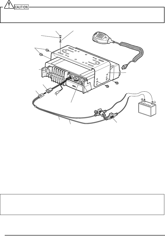
■ Installing the Transceiver
For passenger safety, install the transceiver securely using the supplied mounting bracket and
screw set, so the transceiver will not break loose in the event of a collision.
Note:
• Before installing the transceiver, check how far the mounting screws will extend below the
surface. When drilling mounting holes, be careful not to damage vehicle wiring or parts.
1 Mark the position of the holes in the dash, using the mounting bracket as a
template. Using a 4.2 mm (5/32 inch) drill bit, drill the holes, then attach the
mounting bracket using the supplied screws.
• Mount the transceiver within easy reach of the user and where there is suffi cient
space at the rear of the transceiver for cable connections.
2 Connect the antenna and the supplied power cable to the transceiver.
3 Slide the transceiver into the mounting bracket and secure it using the
supplied hex-headed screws.
8
4 Mount the microphone hanger in a location where it will be within easy
reach of the user.
• The microphone and microphone cable should be mounted in a place where
they will not interfere with the safe operation of the vehicle.
When replacing the fuse in the DC power cable, be sure to replace it with a fuse of the same
value. Never replace a fuse with one that is rated with a higher value.
5 x 16 mm Self-tapping screw
Flat washer
Spring washer
M4 x 6 mm
hex-headed screw with
washer
RF antenna connector
12 V vehicle
battery
Mounting bracket
Microphone
GPS antenna connector
for KRA-40
Fuse
Red (+) cable
Black (–) cable
DC power cable
Power input connector
External
speaker jack
Ignition sense
cable
■ Using the microSD memory card
To install a microSD memory card on this transceiver, please consult your
dealer.
• microSD memory cards (Class 2 or higher) and microSDHC memory cards (Class 2
or higher) can be used.
• SDXC memory cards cannot be used.
• This transceiver is not guaranteed to operate with all microSD memory cards.
(Operations are confi rmed on memory cards for the following brands:
SanDisk, TOSHIBA and Panasonic.)
Compensation Disclaimer
Data stored on the microSD memory card may be altered or lost due to problems with this
transceiver. We do not accept liability in respect of the data stored on your microSD memory
card, failure to save the data properly, loss of data, and any direct or indirect damages.
9
ORIENTATION
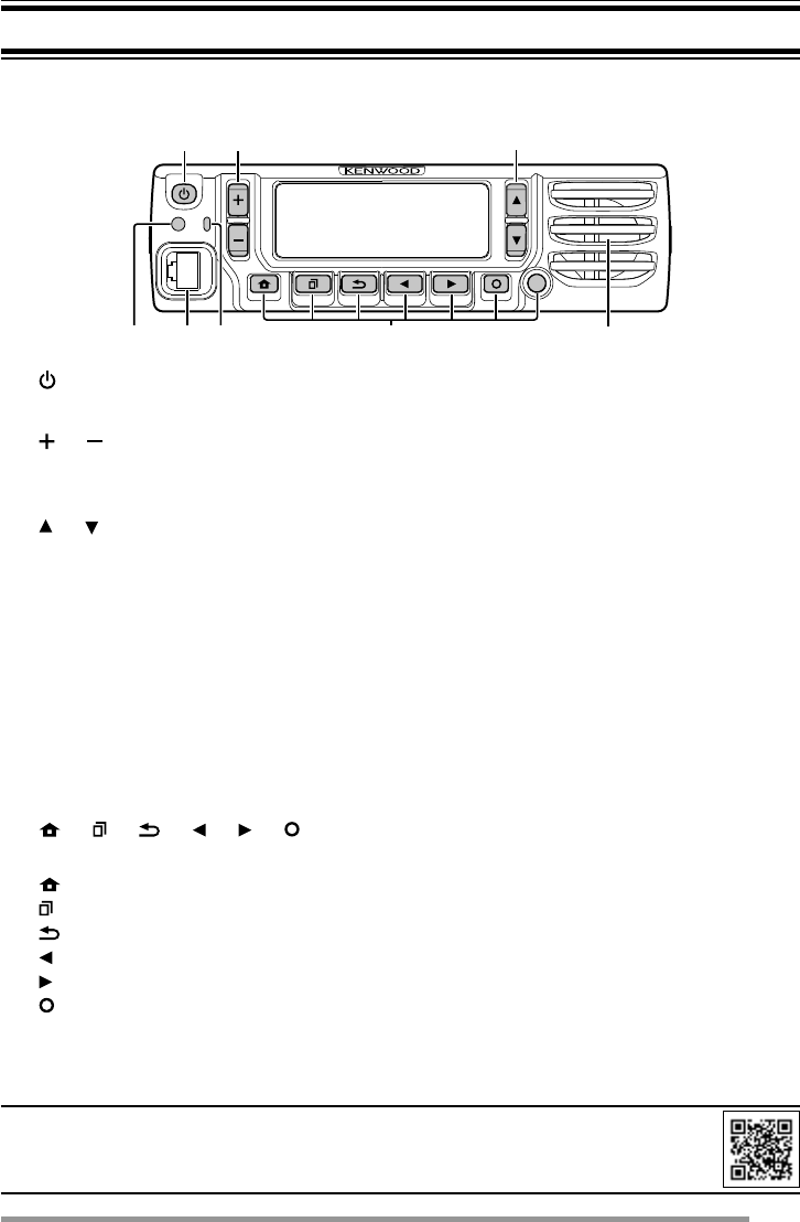
OPERATION PANEL (ATTACHED PANEL OR KCH-19)
ab c
g
efh
d
a [ ] (Power) switch
Press to switch the transceiver ON or OFF.
b [ ] / [ ] keys
Press to activate its programmable function. The default key setting is
[Volume Up]/ [Volume Down].
c [ ] / [ ] keys
Press to activate its programmable function. The default key setting is
[Channel Up]/ [Channel Down].
d Illumination sensor
Sensor for Auto Dimmer Function.
e Microphone jack
Insert the microphone plug into this jack.
f TX/RX Indicator
The indicator lights in different colors to indicate the current status of the
transceiver.
Lights red while transmitting and green while receiving.
g [ ] / [ ] / [ ] / [ ] / [ ] / [ ] / Auxiliary (orange) keys
Press to activate their programmable functions.
[ ] : The default key setting is [Clear].
[ ] : The default key setting is [Menu].
[ ] : The default key setting is [Squelch Off Momentary].
[ ] : The default key setting is [Zone Down].
[ ] : The default key setting is [Zone Up].
[ ] : The default key setting is [Function].
Auxiliary (orange) : The default key setting is [None].
h Speaker
Internal speaker.
For details on programming functions to the keys on your transceiver, please contact
your dealer or refer to the instruction manual available from the following URL.
http://manual2.jvckenwood.com/en_contents/search/
10
DISPLAY
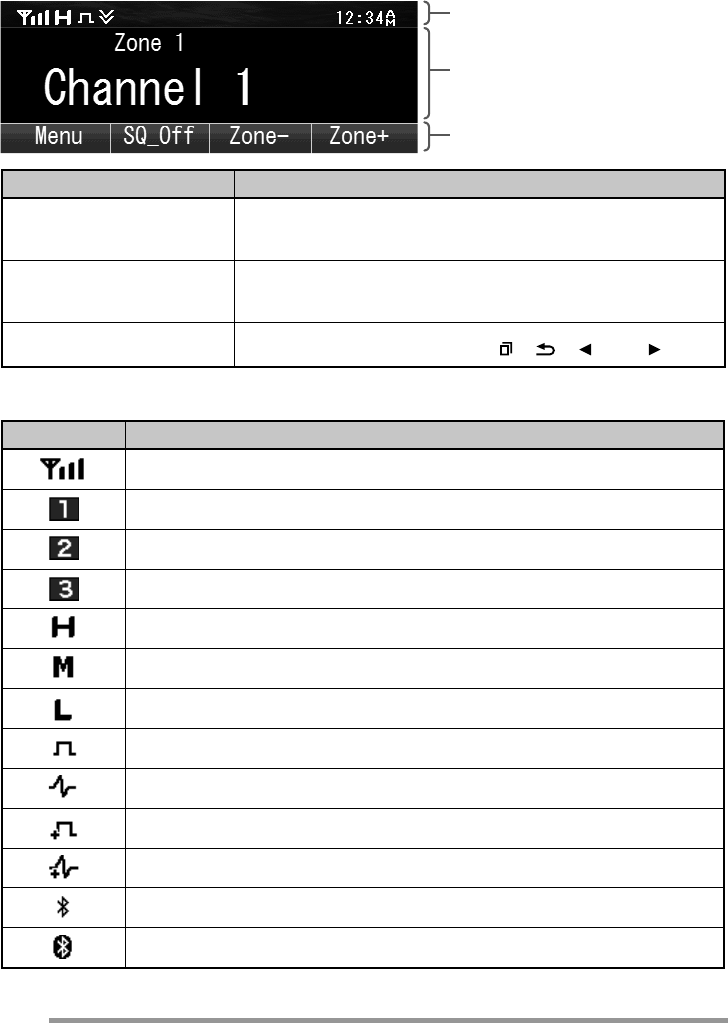
Basic Frame
Function Indicator Area
Main Area
Key Guide Area
Display Area Description
Function Indicator Area Displays the various function indicators, signal
strength indicator and clock.
Main Area Display the information of the transceiver such as
Channel number and Zone number.
Key Guide Area Display the key functions for [ ], [ ], [ ] and [ ] keys.
Function Indicator
Indicator Description
Displays the signal strength.
In Band 1
In Band 2
In Band 3
The channel is using high transmit power.
The channel is using medium transmit power.
The channel is using low transmit power.
In Digital mode (Digital Channel)
In Analog mode (Analog Channel)
In Digital mode (Mixed Channel)
In Analog mode (Mixed Channel)
The Bluetooth function is activated.
Connected to Bluetooth device.
11
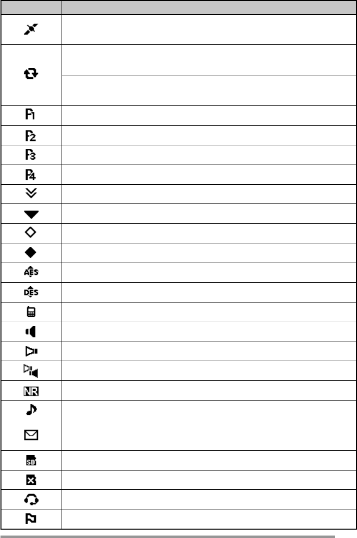
Indicator Description
The GPS position is determined. Blinks when the GPS is unable
to determine the position.
Non-priority Scan or Voting/Site Roaming is in progress.
Blinks when the scan is paused. (green icon)
Priority Scan is in progress.
Blinks when the scan is paused. (red icon)
Indicates Priority channel 1 or Priority Monitor ID 1.
Indicates Priority channel 2 or Priority Monitor ID 2.
Indicates Priority Monitor ID 3.
Indicates Priority Monitor ID 4.
The current channel is added to the scanning sequence.
The current zone is added to the scanning sequence.
The Scrambler function is activated.
The Encryption function is activated.
The Encryption (AES) function is activated.
The Encryption (DES) function is activated.
The Talk Around function is activated.
The Monitor or Squelch Off is activated.
The External Speaker is activated.
The External Speaker (Internal + External) is activated.
The Noise Reduction function is activated.
Blinks when an incoming call matches your Optional Signaling.
A message is stored in memory. Blinks when a new message has
arrived.
The microSD memory card is recognized.
The microSD memory card is not recognized.
The VOX function is activated.
The Site Lock function is activated.
12
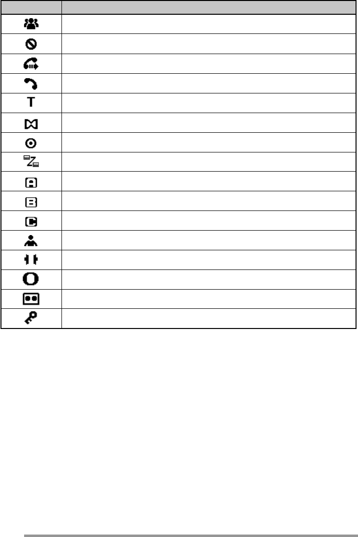
Indicator Description
The Broadcast Call function is activated.
The Surveillance function is activated.
The
Call Diversion is activated.
Telephone ID, RIC (Repeater Interconnect)
The
Tactical Group is activated.
The Horn Alert function is activated.
The Public Address function is activated.
The
Intercom is activated.
AUX A is activated.
AUX B is activated.
AUX C is activated.
The Lone Worker function is activated.
The Compander function is activated.
The Operator Selectable Tone function is activated.
Blinks during Auto Recording.
The Key Lock function is activated.

13
BASIC OPERATION
SWITCHING POWER ON/ OFF
Press [ ] to switch the transceiver ON.
Press [] again to switch the transceiver OFF.
ADJUSTING THE VOLUME
Press the key programmed as [Volume Up] to increase the volume. Press the
key programmed as [Volume Down] to decrease the volume.
SELECTING A ZONE AND CHANNEL
Select the desired zone and channel using the keys programmed as [Zone Up]/
[Zone Down] and [Channel Up]/ [Channel Down].
• The transceivers may have names programmed for zones and channels. The zone
name and channel name can contain up to 16 and 14 characters respectively. While
selecting a zone, the zone name will appear above the channel name.
• If programmed by your dealer, your transceiver will announce the zone and channel
numbers as you change them.
TRANSMITTING
1 Select the desired zone and channel.
2 Press the PTT switch and speak into the microphone. Release the PTT switch
to receive.
• The LED indicator lights red while transmitting and green while receiving a signal.
This indicator can also be disabled by your dealer.
• For best sound quality at the receiving station, hold the microphone approximately
1.5 inches (3 cm to 4 cm) from your mouth.
RECEIVING
Select the desired zone and channel. If signaling has been programmed on the
selected channel, you will hear a call only if the received signal matches your
transceiver settings.

GUIDE DE L'UTILISATEUR
ÉMETTEUR-RÉCEPTEUR NUMÉRIQUE VHF
NX-5700 NX-5700(B)
ÉMETTEUR-RÉCEPTEUR NUMÉRIQUE UHF
NX-5800 NX-5800(B)
ÉMETTEUR-RÉCEPTEUR NUMÉRIQUE 800MHz
NX-5900 NX-5900(B)
Droits d’auteur du micrologiciel
Le titre et la propriété des droits d’auteur pour le micrologiciel intégré dans
la mémoire du produit KENWOOD sont réservés pour JVC KENWOOD
Corporation.
La technologie de codage de la voix AMBE +2™ intégrée dans ce produit est
protégée par des droits sur la propriété intellectuelle y compris les droits de
brevet, les droits d’auteur et les secrets de fabrication du Digital Voice Systems,
Inc. Cette technologie de codage de la voix est autorisée uniquement pour une
utilisation avec cet équipement de communication. Il est formellement interdit
de la part de l’utilisateur de cette technologie d’essayer d’extraire, de retirer,
de décompiler, de procéder à une ingénierie inverse, ou de démonter le code
objet, ou d’aucune autre manière que ce soit de convertir l’objet code dans un
langage humain intelligible. Brevets américains n°. #6,199,037, #6,912,495,
#8,200,497, #7,970,606 et #8,359,197
• SD™ et microSD™ sont des marques commerciales de SD-3C, LLC aux
États-Unis et/ou dans d’autres pays.
• La marque et les logos Bluetooth® sont des marques deposes appartenant
à Bluetooth SIG, Inc. et toute utilisation de ces marques par JVCKENWOOD
Corporation est sous licence. Les autres marques et noms commerciaux sont
ceux de leurs propriétaires respectifs.

GUÍA DEL USUARIO
TRANSCEPTOR DIGITAL VHF
NX-5700 NX-5700(B)
TRANSCEPTOR DIGITAL UHF
NX-5800 NX-5800(B)
TRANSCEPTOR DIGITAL 800MHz
NX-5900 NX-5900(B)
Derechos de propiedad intelectual del firmware
La titularidad y propiedad de los derechos de propiedad intelectual del firmware
integrado en las memorias de los productos KENWOOD están reservados para
JVC KENWOOD Corporation.
La tecnología de codificación de voz AMBE+2™ integrada en este producto
está protegida por derechos de propiedad intelectual incluyendo los derechos
de patente, los derechos de autor y secretos comerciales de Digital Voice
Systems, Inc. Esta tecnología de codificación de voz otorga licencia para su
uso únicamente dentro de este equipo de comunicaciones.
Está explícitamente prohibido que el usuario de esta tecnología intente extraer,
retirar, descompilar, realizer ingeniería inversa, o desmontar el código objeto, o
convertir de cualquier otra manera el código objeto a una forma legible para el
ser humano. Los números de patente de los EE.UU. #6,199,037, #6,912,495,
#8,200,497, #7,970,606 y #8,359,197
• SD™ y microSD™ son marcas comerciales de SD-3C, LLC en los Estados
Unidos y/o en otros países.
• La marca denominativa y los logos de Bluetooth® son marcas comerciales
registradas propiedad de Bluetooth SIG, Inc. y cualquier uso de dichas
marcas por JVC KENWOOD Corporation se encuentra bajo licencia. Otras
marcas y nombres comerciales pertenecen a sus respectivos dueños.

© 2015
MANDATORY SAFETY INSTRUCTIONS TO INSTALLERS AND USERS
• Use only manufacturer or dealer supplied antennas.
• Antenna Minimum Safe Distance: 40 cm (16 inches), 50% duty Cycle.
• Antenna Gain: 0 dBd referenced to a dipole.
The Federal Communications Commission has adopted a safety standard
for human exposure to RF (Radio Frequency) energy which is below the
OSHA (Occupational Safety and Health Act) limits.
•
Antenna Mounting: The antenna supplied by the manufacturer or radio
dealer must not be mounted at a location such that during radio transmission,
any person or persons can come closer than the above indicated minimum
safe distance to the antenna, i.e. 40 cm (16 inches) , 50% duty Cycle.
• To comply with current FCC RF Exposure limits, the antenna must
be installed at or exceeding the minimum safe distance shown
above, and in accordance with the requirements of the antenna
manufacturer or supplier.
•
Vehicle installation: The antenna can be mounted at the center of a
vehicle metal roof or trunk lid, if the minimum safe distance is observed.
• Base Station Installation: The antenna should be fixed-mounted on
an outdoor permanent structure. RF Exposure compliance must be
addressed at the time of installation.
Antenna substitution: Do not substitute any antenna for the one supplied
or recommended by the manufacturer or radio dealer.
You may be exposing person or persons to excess radio frequency radiation.
You may contact your radio dealer or the manufacturer for further instructions.
Maintain a separation distance from the antenna to person(s) of
at least 40 cm (16 inches), 50% duty Cycle.
“This transmitter is authorized to operate with a maximum duty factor of 50%, in
typical push-to-talk mode, for satisfying FCC RF exposure compliance requirements.”
You, as the qualified end-user of this radio device must control the exposure
conditions of bystanders to ensure the minimum separation distance (above) is
maintained between the antenna and nearby persons for satisfying RF Exposure
compliance. The operation of this transmitter must satisfy the requirements of
Occupational/Controlled Exposure Environment, for work-related use, transmit
only when person(s) are at least the minimum distance from the properly installed,
externally mounted antenna. Transmit only when people outside the vehicle are at
least the recommended minimum lateral distance away from the antenna/vehicle.
B59-2723-00