JVCKENWOOD K9X004 Card Printer w/Built-in RFID Unit User Manual
JVC KENWOOD Corporation Card Printer w/Built-in RFID Unit
Contents
- 1. User manual 1 of 3
- 2. User manual 2 of 3
- 3. User manual 3 of 3
User manual 2 of 3
③
③
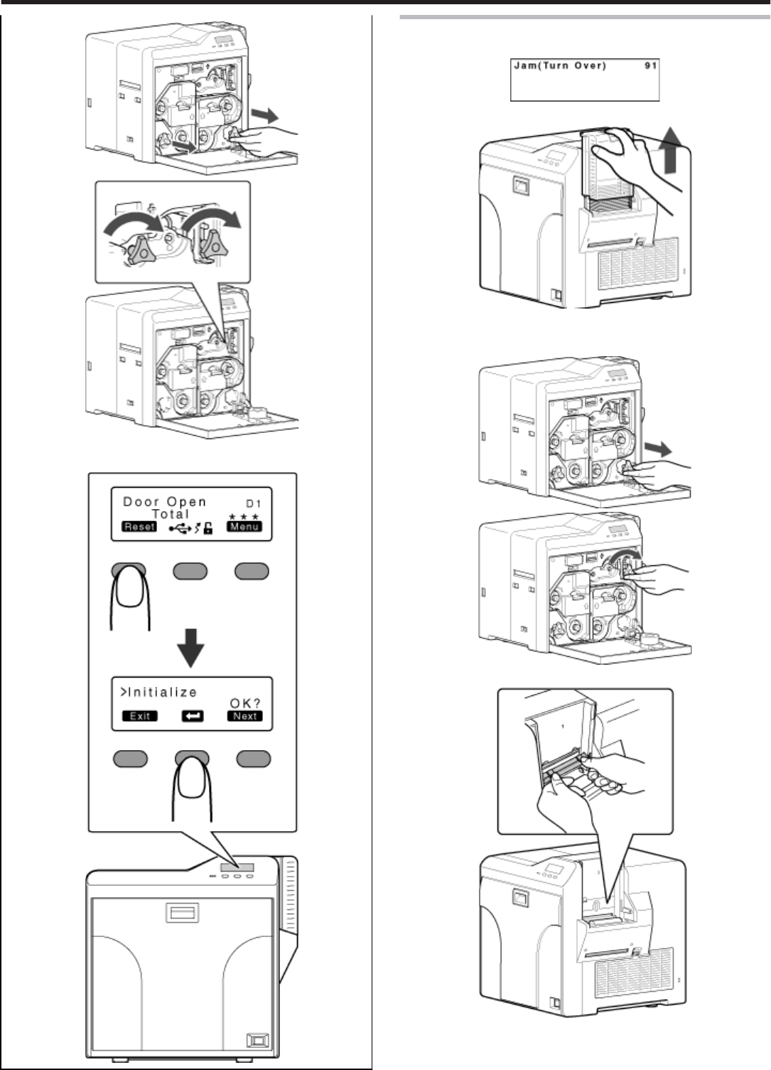
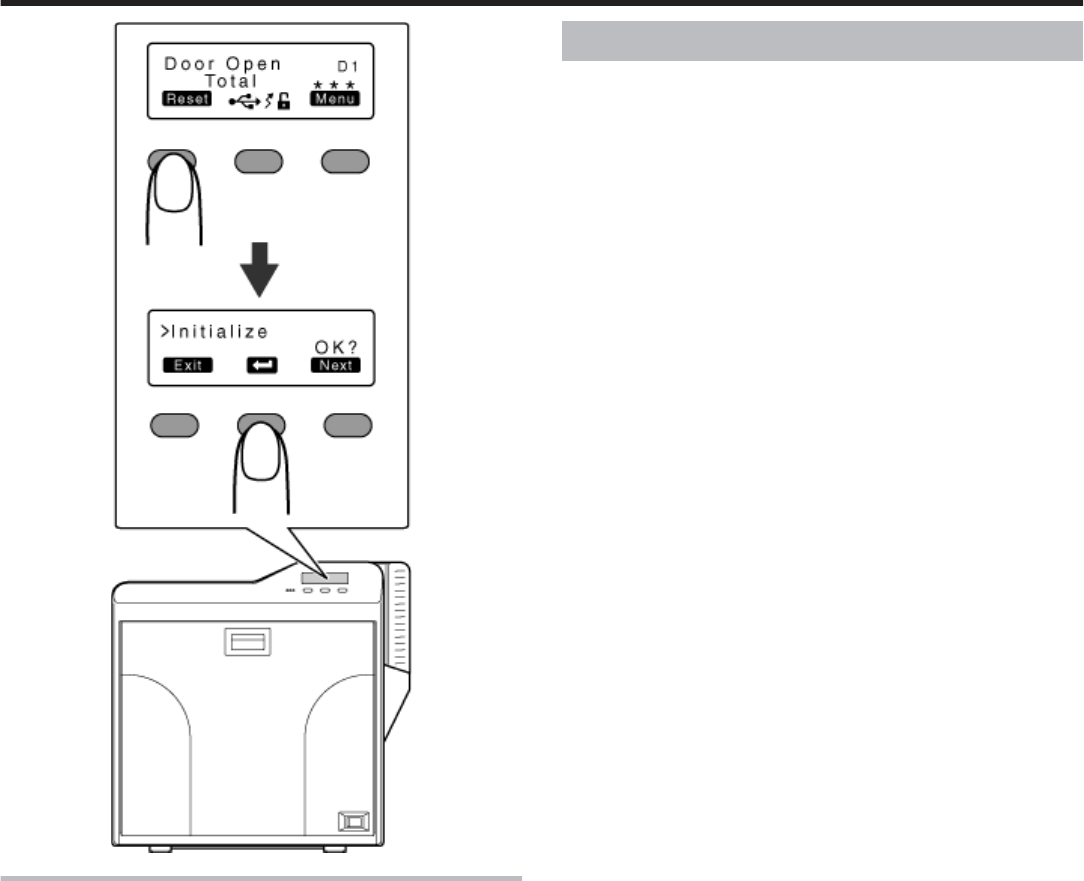
Close the printer door, and press [RESET]DB to reset the
printer.
Error code 91
●Card jam in the turnover unit
Remove the card hopper.
Open the printer door, and remove the cleaning unit.
Use the jog dial to turn the cleaning unit in the clockwise direction.
●Open the card hopper cover, and remove the card if this is possible.
Use the jog dial to turn the turnover unit slightly in both the left and
right directions.
●If the card is protruded from the turnover unit, the turnover unit cannot
be turned.
Troubleshooting
45
Turn the turnover unit and cleaning unit at the same time in opposite
directions to move the card to the turnover unit.
Move the card to the turnover unit.
●Turn the turnover unit and cleaning unit in opposite directions.
Close the printer door, and press [RESET]DB to reset the printer.
●The card is discharged from the NG card outlet or card stacker.
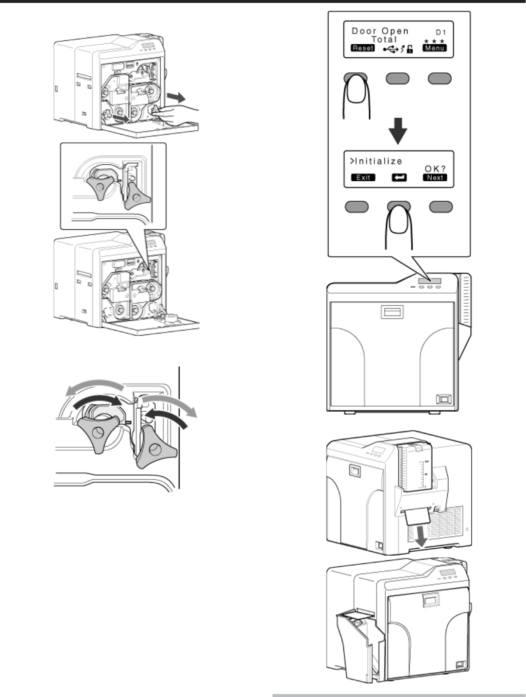
Error code 92
●Card jam in the magnetic encoder unit.
Troubleshooting
46
Open the printer door.
Restore the card to the magnetic encoder unit.
●Use the jog dial to turn the cleaning unit.
Turn the jog dial at the turnover unit to adjust the unit to a vertical posi-
tion.
●While doing so, make use of the printer’s label as a reference.
Move the card to the center of the turnover unit
① Maintain the turnover unit in the vertical position.
② Turn the jog dial at the cleaning unit.
●Check to ensure that the card moves to the turnover unit.
Turn the jog dial attached to the turnover and cleaning units at the
same time in opposite directions.
●Set the turnover unit to the horizontal position.
Turn the jog dial of the turnover unit clockwise to an angle of 45@.
●While doing so, make use of the printer’s label as a reference.
Turn the jog dial at the cleaning unit in the anti-clockwise direction.
●The card is discharged from the NG card outlet.
Press [RESET]DB to reset the printer.
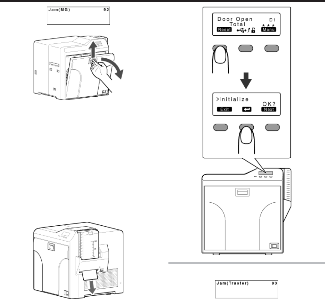
Error code 93
●Card jam in the retransfer unit
Press [Reset]DB to reset the printer.
Troubleshooting
47
●The card is discharged from the NG card outlet or card stacker.
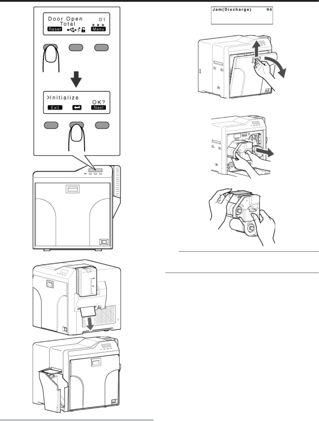
Error code 94
●Card jam in the discharge unit.
Open the printer door.
Remove the retransfer film cassette (on the left), and check the printer
interior.
●If the card is found adhered to the retransfer film, remove the card.
Note:
●If the card cannot be removed from the retransfer film cassette (on the
left), do not try to do so forcefully. Consult our authorized dealers or
servicing personnel.
Close the printer door, and press [RESET]DB to reset the printer.
Troubleshooting
48
Card has run out
●"Replenish the cards." ' page 28
Ink Ribbon
●"Ink ribbon has run out" ' page 29
●"Ink ribbon is broken" ' page 30
Troubleshooting
49
Retransfer Film
●"Retransfer film has run out" ' page 31
●"Retransfer film is broken" ' page 32
Unable to fit retransfer film cassette into printer
●With the printer door closed. turn on the power, and cancel the trans-
port mode.
●When in the transport mode, the retransfer film cassette cannot be in-
stalled to the printer with the retransfer film attached.
"Transport mode setting" (' page 24)
Unable to produce desired printing results
Lines appear on card after printing
●
●
"Clean the thermal head." ' page 41
Colors on card appear faded after printing
●"Clean the cleaning roller." ' page 34
●"Clean the fan filter." ' page 35
●"Clean the card feed roller/heating roller." ' page 36
●"Clean the bobbin holders." ' page 40
Peeling occurs on card after printing
●"Check the retransfer mode settings." ' page 83
Overall printing quality is poor
●"Clean the cleaning roller." ' page 34
●"Clean the fan filter." ' page 35
●"Clean the card feed roller/heating roller." ' page 36
●"Clean the bobbin holders." ' page 40
●Is the printing face of the card dirty?
Use a clean card.
Card is printed in a single color
●Is the print settings set to single-color printing?
●Is the software application settings set to single-color printing?
Check the print settings.
Strange characters or images are printed
●Is the driver for this printer selected on the computer?
Select the driver for this printer.
●Is the USB cable connection loose?
Plug in the USB cable properly.
Retransfer cannot be performed successfully
●Is the printing face of the card dirty?
Use a clean card.
●Is the surrounding temperature or card surface temperature too
low?
Use after the ambient and card surface temperatures have
reached the range specified in the operating environment condi-
tions.
●Is the retransfer speed setting value too high?
Set to a value that is smaller than +2 (between +1 and -3).
●Is the temperature of the retransfer roller too low?
Set to a value that is larger than +1 (+2).
Troubleshooting
50
Printer not operating as desired
Card is not fed into the printer
●
●
Is the card feed path dirty?
Clean the card feed roller/heating roller.
"Cleaning the card feed roller/heating roller" (' page 36)
●Is the paper load roller dirty?
Apply alcohol (sold separately) to a wiper (sold separately), and
use it to clean the paper load roller.
●Is the card thickness correctly adjusted?
Check the card separator settings.
"Card separator settings" (' page 56)
●Are the cards adhered to one another?
Cards may be adhered to one another due to static. Separate the
cards one by one before setting them in the printer.
Power does not turn on
●Is the power switch turned off? ({ position)
Turn on the power. (I position)
●Is the power cord disconnected?
Plug in the power cord properly.
●Is there electricity supply from the outlet?
Try connecting another electrical device to the outlet. If the device
works normally, then it could be due to malfunctioning of the
printer. Consult our authorized dealers.
Printing does not start or stops halfway
●Is the printer door open?
Close the printer door properly, and reset the printer.
"Initialization" (' page 17)
●Is the printer connected to a computer?
Connect the printer to a computer correctly using a USB/LAN ca-
ble.
●Is the length of the USB cable too long?
A USB cable with a length of not more than 2 m is recommended.
●Are cards set into the printer?
Set the cards correctly.
"Replenishing cards" (' page 28)
●Is an ink ribbon/retransfer film installed?
Install an ink ribbon/retransfer film correctly.
"Installing the ink ribbon" (' page 29)
"Attaching the retransfer film" (' page 31)
●Is the driver for this printer selected?
Select the driver for this printer.
Before sending printer for repair
Enter the symptoms into the troubleshooting sheet.
Printing the troubleshooting sheet
●Clicking the Print icon displays a PDF file.
●Print out the PDF file and enter accordingly.
Installation and Connection
●"Printer Installation" ' page 52
●"Power Cord Connection" ' page 52
●"Card Stacker (Supplied)" ' page 52
Printing Media
●"Installing the ink ribbon" ' page 53
●"Attaching the retransfer film" ' page 54
●"Setting Cards" ' page 55
Printer and Computer Connection
●"Connecting with a USB Cable" ' page 57
●"Connecting with a LAN Cable" ' page 57
●"Connecting Multiple Printers" ' page 57
Computer Settings
●"Software" ' page 58
●"Install" ' page 58
●"Uninstall" ' page 69
●"IP Sec" ' page 72
●"Printer Driver Settings" ' page 74
●"Port Monitor Settings" ' page 80
●"Status Monitor Settings" ' page 80
Printer Settings
●"Operation Panel" ' page 11
●"Setting using the operation panel" ' page 17
Troubleshooting
51
Installation and Connection
Printer Installation
Note:
●Using the printer in an environment beyond the operating ambient tem-
perature range may result in retransfer or printing errors. Check the
“Precautions on installation location” and “Operating environment con-
ditions” specifications.
"Precautions on installation location" (' page 5)
"Operating environment conditions" (' page 9)
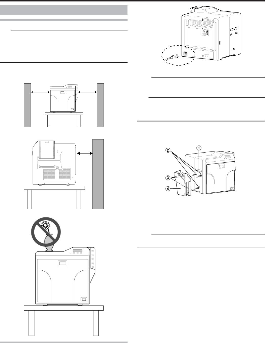
Ventilation holes for the cooling fan are located at the rear and side of the
printer.
●Install the printer by allowing a clearance of at least 20 cm between its
sides and surrounding walls.
●Allow a clearance of at least 10 cm between the rear of the printer and
the wall.
●Do not place any object on the printer.
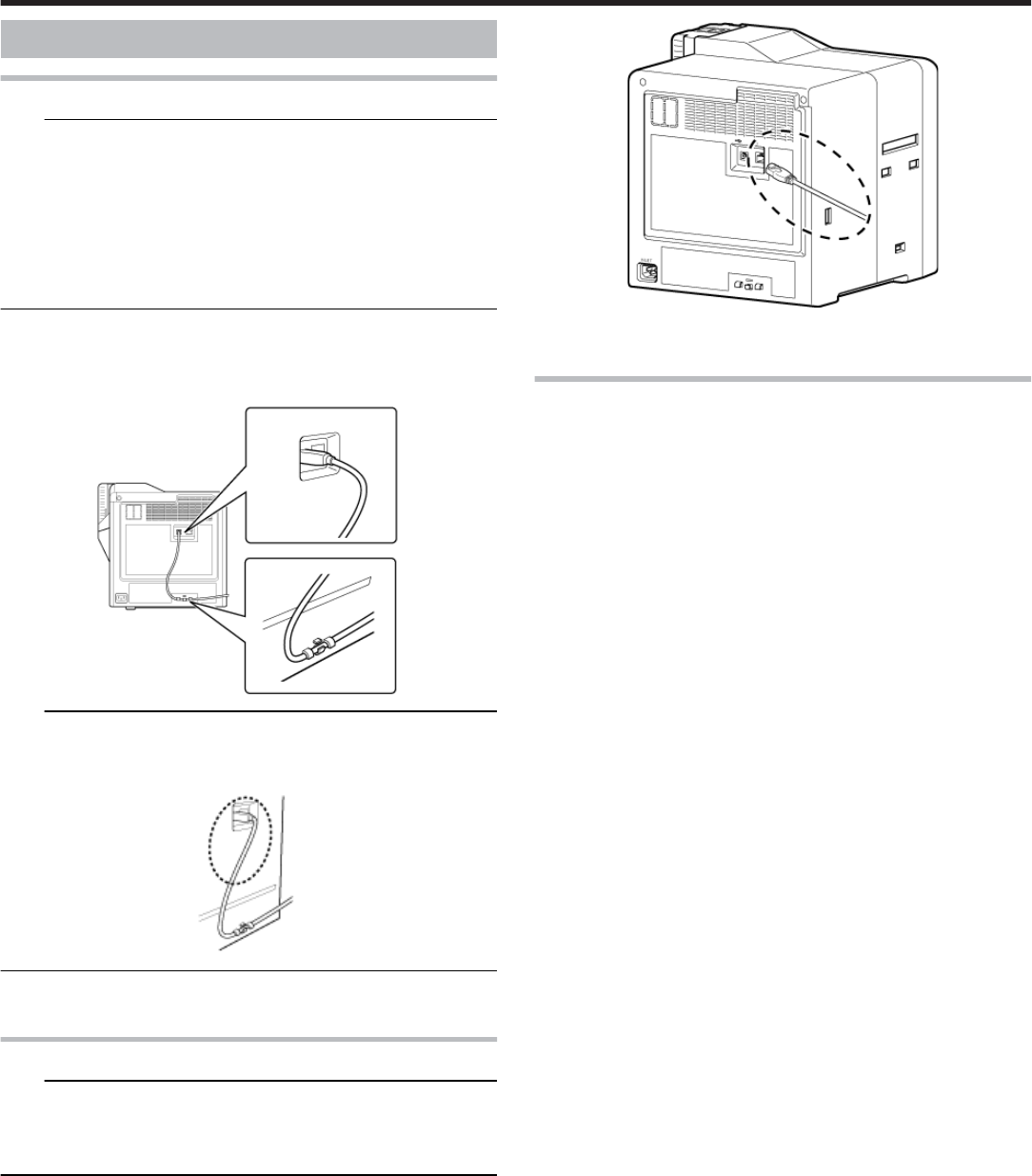
Power Cord Connection
Insert the power cord (supplied) to the power input terminal at the rear
of the printer.
Plug the power cord (supplied) into an outlet.
Memo:
●Make use of an AVR (automatic voltage regulator) to prevent any fluc-
tuation in voltage. Alternatively, an uninterruptible power supply is rec-
ommended in case momentary power outage occurs.
Note:
●Make sure that the power outlet is grounded and used as a dedicated
power source for the printer.
●It must not be shared with other power supply facilities.
Card Stacker (Supplied)
Hook the tab on the card stacker to the card stacker attachment slot.
① Card outlet
② Card stacker attachment slot
③ Tab
④ Card stacker
Memo:
●The card stacker is able to store up to about 100 cards with a thickness
of 0.76 mm, or about 300 cards with a thickness of 0.25 mm.
Setup
52
Printing Media
Installing the ink ribbon
Note:
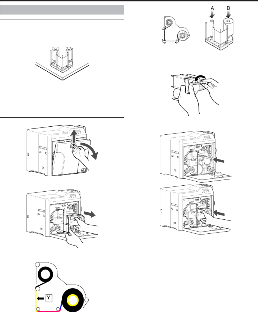
●Stand the cassette on a flat surface as illustrated in the diagram. Avoid
doing so on a floor as dust attached to the retransfer film may cause
printing errors.
●Do not touch the inked surface (the side that faces outward when in-
stalled) with your hand. Touching it may cause printing errors. Put on
the supplied gloves when handling the ink ribbon.
●When handling the cassette, hold it with both hands. Accidentally drop-
ping the cassette may damage it or result in injuries.
●Do not perform work on the printer door. Do not place heavy objects or
apply load on the printer. Doing so may damage it.
Open the printer door.
Press and hold down the cassette button, and pull out the ink ribbon
cassette (on the right) to remove the ink ribbon.
Install a new ink ribbon.
●Install while referring to the indication on the label of the cassette.
① With the inked surface facing outward, align the yellow side of the
unused ribbon with the arrow on the cassette, and unwind it along
the three shafts.
② Insert the ink ribbon firmly into the bobbin holders with the ribbon set
to the far end of the guides.
●A: take-up side (black)
●B: unused side (yellow)
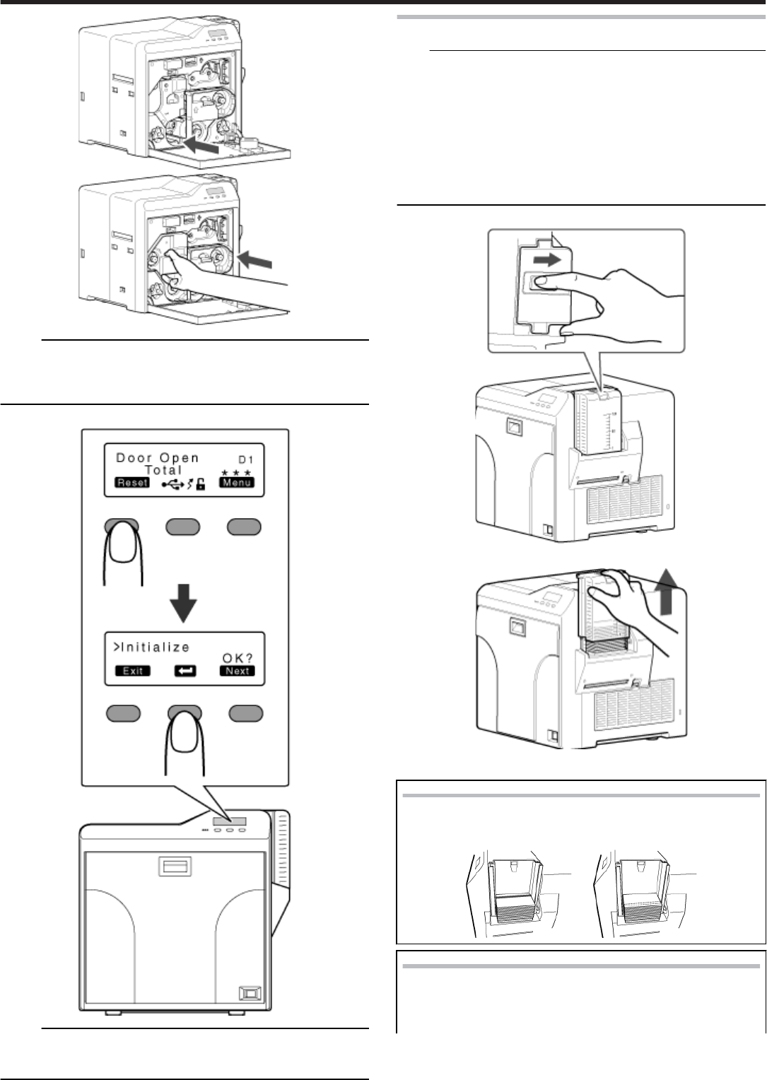
Remove any slack in the ink ribbon.
① Hold the cassette.
② Turn the knob in the direction indicated by the arrow.
Insert the cassette all the way in along the guide rail until a “click”
sound is heard. Close the printer door.
Press [Reset]DB to reset the printer.
Setup
53

Attaching the retransfer film
Note:
●Stand the cassette on a flat surface as illustrated in the diagram. Avoid
doing so on a floor as dust attached to the retransfer film may cause
printing errors.
●Do not touch the retransfer face (the side that faces outward when in-
stalled) with your hand. Touching it may cause printing errors. Put on
the supplied gloves when handling the retransfer film.
●When handling the cassette, hold it with both hands. Accidentally drop-
ping the cassette may damage it or result in injuries.
●When installing a new film, make sure that at least three black lines are
wound onto the take-up side. Insufficient winding may cause the printer
to malfunction.
●Do not perform work on the printer door. Do not place heavy objects or
apply load on the printer. Doing so may damage it.
Open the printer door.
Press and hold down the cassette button, and pull out the retransfer
film cassette (on the left) to remove the retransfer film.
Install a new retransfer film.
●Install while referring to the indication on the label of the cassette.
① When installing the retransfer film, make sure that at least three
black lines are wound onto the take-up side.
② With the retransfer face facing outward, align the unused side of the
film with the arrow on the cassette, and unwind it along the three
shafts.
③ Insert the retransfer film firmly into the bobbin holders with the film
set to the far end of the guides.
●A: take-up side (black)
●B: unused side (green)
Remove any slack in the film.
① Hold the retransfer film cassette.
② Turn the knob in the direction indicated by the arrow.
Insert the cassette all the way in along the guide rail until a “click”
sound is heard. Close the printer door.
Setup
54
Memo:
●If the retransfer film cassette does not fit into the printer, turn on the
power of the printer with the printer door closed to cancel the transport
mode.
"Transport mode setting" (' page 24)
Press [Reset]DB to reset the printer.
Memo:
●When attaching a new retransfer film, it is recommended that you for-
ward the film by one or two images before printing.
"Initializing printer when attaching the cassette" (' page 17)
Setting Cards
Note:
●When using new cards, separate them one by one before setting them
in the printer. Cards may be adhered to each other due to static, thus
causing card jams.
●Align the cards before setting them in the printer. Otherwise, the card
hopper cover may not close properly, and this may damage the printer.
●Printing the card on the side with the magnetic stripe may cause print-
ing errors or damage to the card’s functions. If you want to do so, con-
sult our authorized dealers in advance.
●To set cards with both functions (magnetic stripe and contact IC), fol-
low the procedure for setting the contact IC card.
Set the card hopper knob to [OPEN].
Lift to remove the card hopper cover.
Align the orientation of the cards, and set them in the printer.
Magnetic cards
●
●
Set the card with the magnetic stripe facing upward and toward
the printer, or facing downward and toward you.
ISO contact IC cards
●Set the card with the Contact IC terminal facing upward and to-
ward the rear of the printer, or downward and toward the front
of the printer.
Setup
55
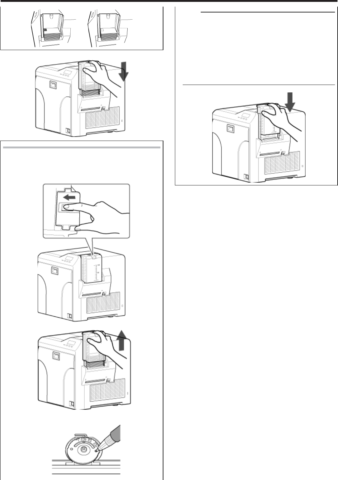
Install the card hopper cover.
Adjusting Card Thickness
●
●
This printer can print cards with a thickness between 0.25 mm
and 1.00 mm.
This is adjusted to a thickness of 0.76 mm by default.
① Set the card hopper knob to [LOCK].
② Remove the card hopper.
③ Insert a ballpoint pen into the card separator hole, and turn
slowly.
Memo:
●If the card cannot be discharged during printing, adjust the
card thickness by turning the card separator in the clockwise
direction by one scale at a time.
●If two cards are discharged at a time during printing, adjust
the card thickness by turning the card separator in the anti-
clockwise direction by one scale at a time.
●If cards of different thickness are used frequently, purchase
of an additional card hopper according to the card thickness
is recommended.
For details on the purchase of card hoppers, please consult
our authorized dealers.
④ Attach the card hopper cover.
Setup
56
Printer and Computer Connection
Connecting with a USB Cable
Note:
●While printing is in progress, do not turn off the power of the host com-
puter, or switch it to the sleep or standby mode. Doing so may stop the
movement of the cards inside the printer.
●Plug the USB cable in correctly and firmly.
●Do not connect the cable to the USB connectors on the monitor or key-
board of the host computer. The printer may not be correctly recog-
nized.
●When using a USB hub, make use of one that is directly connected to
the host computer.
Turn off the power of the printer and host computer.
Plug the USB cable into the USB cable connection terminal at the rear
of the printer," and pass the" ' page 7 USB cable through the cable
clamp.
Note:
●As illustrated in the diagram, do not pull the USB cable excessively to-
ward the cable clamp. Doing so may subject the USB connector of the
printer to stress, thus resulting in connection problems.
Plug the other end of the USB cable into the USB cable connection
terminal of the host computer.
Connecting with a LAN Cable
Note:
●Plug the LAN cable in correctly and firmly.
●Make use of a shielded LAN cable to avoid any malfunction.
●If a USB cable is also connected at the same time when the power is
turned on, priority will be given to USB.
Turn off the power of the printer and host computer.
Plug the LAN cable into the LAN cable connection terminal at the rear
of the printer.
Plug the other end of the LAN cable into the LAN cable connection ter-
minal of the host computer.
Connecting Multiple Printers
●To connect multiple printer units to one host computer via USB, assign
a different unit number from 1 to 10 to each of the printers.
"Unit number setting" (' page 23)
●To connect multiple printers to the same network, set a different IP ad-
dress for each printer.
Setup
57
Computer Settings
Note:
"Contents of this manual" (' page 3)
●Reprint of this manual without prior consent is strictly prohibited.
●The contents of this manual and the specifications and appearance of
the printer may be modified without prior notice.
●Illustrations used in this manual may differ slightly from the actual prod-
uct.
●Microsoft and Windows are the registered trademarks or trademarks of
Microsoft Corporation in the United States and other countries. Micro-
soft Windows Vista operating system (Japanese), Microsoft Win-
dows XP operating system (Japanese), and Microsoft Windows
2000 operating system (Japanese) are denoted in this manual as Win-
dows Vista, Windows XP, and Windows 2000 respectively.
●Screenshots used are in accordance with the guidelines of Microsoft
Corporation.
●This product includes software developed by the OpenSSL Project for
use in the OpenSSL Toolkit. (http://www.openssl.org/)
This product includes cryptographic software written by Eric Young
(eay@cryptsoft.com).
This product includes software written by Tim Hudson (tjh@crypt-
soft.com).
System Requirements
●
●
The printer software runs under the following environments.
●Microsoft Windows Vista 32 bit (Service Pack 1, Japanese)
●Microsoft Windows XP 32 bit (Service Pack 2/3, Japanese)
●Microsoft Windows 2000 Professional 32bit (Service Pack 4,
Japanese)
●"Software" ' page 58
●"Install" ' page 58
●"Uninstall" ' page 69
●"IP Sec" ' page 72
●"Printer Driver Settings" ' page 74
●"Port Monitor Settings" ' page 80
●"Status Monitor Settings" ' page 80
●"Inline Encoding" ' page 86
●"List of Error Codes" ' page 87
●"Frequently Asked Questions" ' page 89
Software
●Using the installer (automatic execution program) enables easy
installation of the printer software, while the folder where the
Electronic Manual is stored can be opened easily at the same
time.
●The installer application installs programs based on the Win-
dows language settings. To change the language setting of a
program, use the language selection pull-down menu.
Software License Agreement
●Users need to agree to the terms and conditions in the “Software Li-
cense Agreement” before using the software. Please read through the
License Agreement.
“Software License Agreement”
Install
Note:
●Administrator authority is required to install or uninstall the software.
●To install/uninstall the software, log into the system as an administra-
tive user (Administrators group).
●A part of the illustrations in this electronic manual may not be displayed
depending on the computer’s environment. Skip the procedures in this
case.
●"Printer Driver" ' page 58
●"Network Sharing of Printer" ' page 64
●"Status Monitor" ' page 80
●"USB Driver" ' page 67
●"Electronic Manual" ' page 69
Printer Driver
Installing the printer driver
USB connection
Note:
●Do not turn on the power of the printer until instruction asking you to do
so appears on the installer.
●Do not connect the printer to the USB until instruction asking you to do
so appears on the installer.
●You need to enable the USB hub before connecting the printer via this
hub. Do not connect the printer to the USB hub until it is enabled.
●Exit all applications that are currently running.
●If document printing is currently in progress, wait for all the jobs to com-
plete.
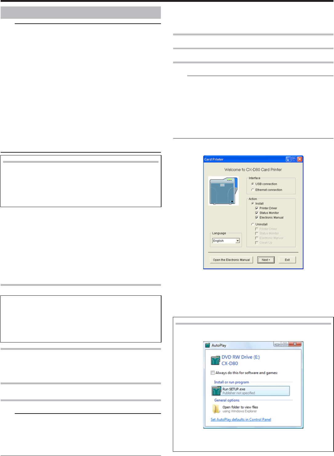
Start up Windows, and set the CD-ROM supplied into the PC.
●The Card Printer Setup screen appears.
●If the CD-ROM of the PC is set to run automatically, the installer will be
executed automatically.
If the installer is not automatically initiated, double-click [Setup.exe] in
the CD-ROM folder.
●If you are not using the [Setup.exe] automatic execution program in the
CD-ROM, start the installer for the printer driver by double-clicking the
following file in the CD-ROM: “English\USB_Soft\install.exe”.
Windows Vista
●A [Auto play] screen appears.
●Clicking [Run SETUP.exe] displays the [User Account Control]
screen.
●Clicking [Yes] displays the [Card Printer Setup] screen.
① Select the language to use from the pull-down menu.
●Selecting [English] switches the program to the English version.
●Selecting [Japanese] switches the program to the Japanese version.
Setup
58
② Select [Interface].
●Check to ensure that the [USB connection] checkbox is selected.
③ Select [Action].
●Select [Install] to start installation. Select [Uninstall] to start uninstal-
lation.
④ Select the [Printer Driver] checkbox.
Memo:
●You can select the [Status Monitor] and [Electronic Manual] checkbox-
es to install them simultaneously. Selecting all checkboxes starts instal-
lation in the order of the electronic manual, printer driver, followed by
[Status Monitor].
●The same status monitor can be used for printers connected via USB
and Ethernet.
●
●
Clicking [Open the Electronic Manual] opens the electronic
manual.
●Clicking [Exit] ends the installation.
Click [Next].
●The [Install CX-D80 USB Printer] screen appears.
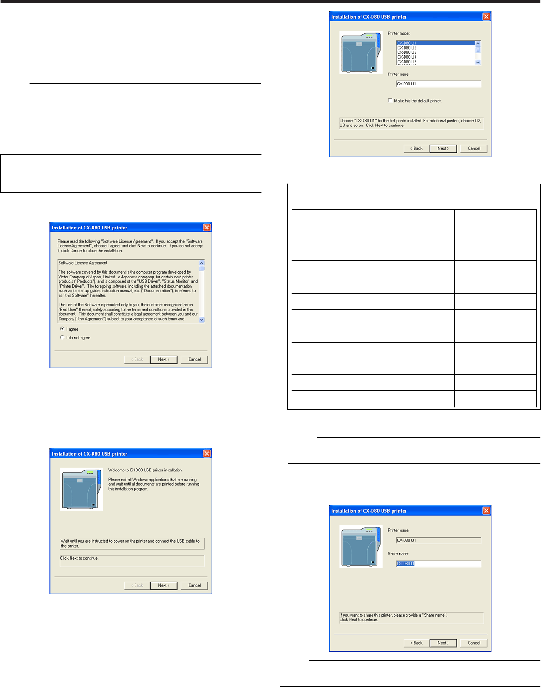
Read through the “Software License Agreement”.
●If you agree to the terms and conditions of the agreement, select the [I
agree] checkbox.
●If you do not agree, click [Cancel] to stop the installation.
Click [Next].
●A Start Installation screen appears.
Check the details, followed by clicking [Next].
●The [Printer Model] and [Printer Name] setting screens appear.
① Select a printer model according to the unit number of the printer.
"Unit number setting" (' page 23)
●Select a printer model according to the unit number of the
printer. Installation may fail if the combination is incorrect.
Printer Unit
Number
Printer Model Op-
tions
USB Device Name
1 (Factory
Setting)
CX-D80 U1 CX-7000 U1
2 CX-D80 U2 CX-D80 U2
3 CX-D80 U3 CX-D80 U3
4 CX-D80 U4 CX-D80 U4
5 CX-D80 U5 CX-D80 U5
6 CX-D80 U6 CX-D80 U6
7 CX-D80 U7 CX-D80 U7
8 CX-D80 U8 CX-D80 U8
9 CX-D80 U9 CX-D80 U9
10 CX-D80 U10 CX-D80 U10
② Enter the printer name.
③ Select the [Make this the default printer] checkbox if necessary.
Memo:
●Doing so enables you to use it as a default printer after installation is
complete.
Click [Next].
●The Enter Shared Name screen appears.
●nter the shared name when you are sharing a printer.
Memo:
●Doing so enables you to use it as a default printer after installation is
complete.
Click [Next].
●The Port Selection screen appears.
●Select [CX-D80U Port] from [Create a new port].
Setup
59
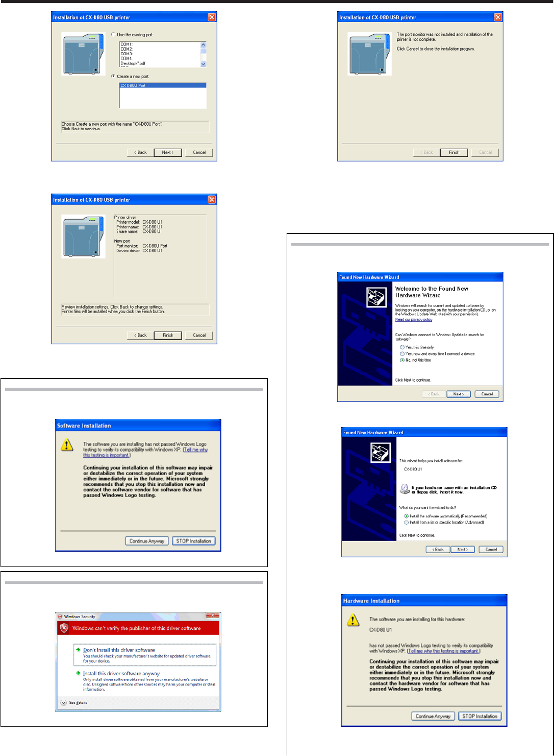
Click [Next].
●An Installation Information confirmation screen appears.
Check the installation information, followed by clicking [Finish].
●To change the settings, click [Back].
Windows XP
●
●
A [Software Installation] screen appears.
① Click [Continue Anyway].
Windows Vista
●A Windows Security screen appears.
① Click on “Install this printer driver”.
●A USB Cable Connection instruction screen appears.
Connect the printer and PC using a USB cable.
Turn on the power of the printer.
●Installation starts automatically after the printer is detected.
●Installation does not start if connection is improper. When this occurs,
check the connection.
Windows XP
A [Found New Hardware Wizard] screen appears.
① Select [No, not this time], and click [Next].
●An Installation Selection screen appears.
② Select [Install the software automatically(Recommended)],
and click [Next].
●A [Hardware Installation] screen appears.
③ Click [Continue Anyway].
●A [Found New Hardware Wizard] screen appears.
Setup
60
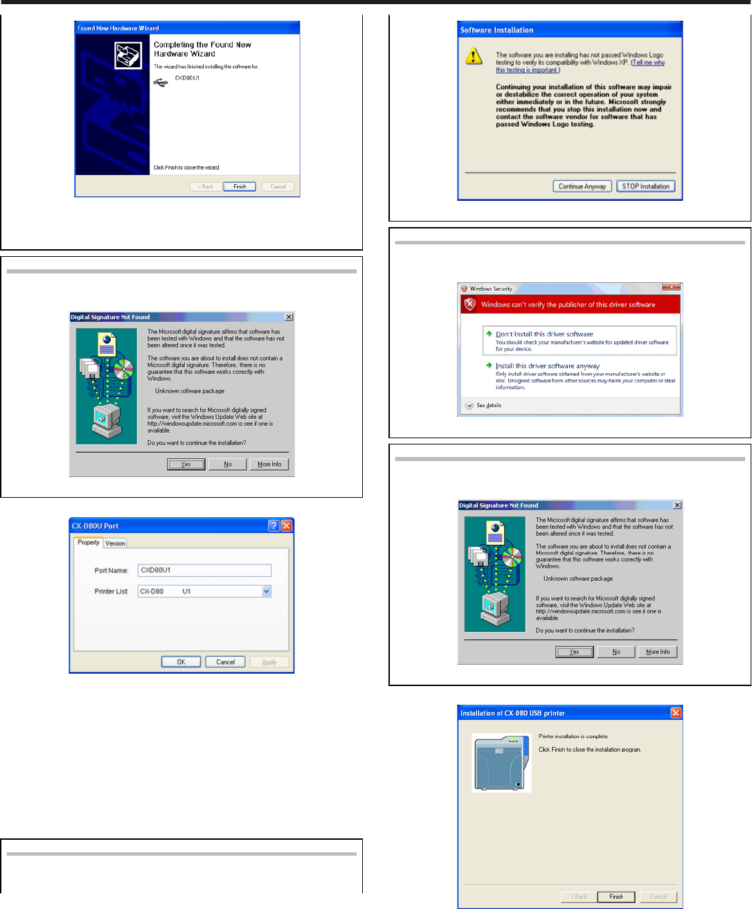
④
④
Click [Finish].
●A [Software Installation] screen appears.
⑤ Click [Continue Anyway].
Windows 2000
●A [Digital Signature Not Found] screen appears.
① Click [yes].
●A [CX-D80N Port] screen appears.
Select the [Property] tab.
① Select this printer from [Printer List].
●USB connection is improper if [Not Connected] appears in the printer
list. When this occurs, exit installation and restart the installation
process.
●If [Not Selected] appears in the [Printer List], select a USB device
name that coincides with the printer unit number that is currently be-
ing installed from the pull-down list.
② Enter the port name.
Click [OK].
Windows XP
●A [Software Installation] screen appears.
.
① Click [Continue Anyway].
Windows Vista
●A Windows Security screen appears.
① Click on “Install this printer driver”.
Windows 2000
●A [Digital Signature Not Found] screen appears.
① Click [Yes].
●A Printer Installation Completed screen appears.
Click [Finish].
●Exits the installation program.
Open the printer in the [Control Panel].
●Check to ensure that the printer is added.
Setup
61
Windows XP
.
Windows Vista
.
Windows 2000 (Example)
.
Note:
●To delete a printer, execute “Uninstall printer driver” after restarting
Windows.
Ethernet (LAN) Connection
Note:
●Configure the IP address and other necessary settings for the printer in
advance.
●Do not connect the printer to the USB port.
●Do not connect the printer to the Ethernet (LAN) until instruction asking
you to do so appears on the installer.
●Do not turn on the power of the printer until instruction asking you to do
so appears on the installer.
●You need to enable the LAN hub before connecting the printer via this
hub.
●Exit all applications that are currently running.
●If document printing is currently in progress, wait for all the jobs to com-
plete.
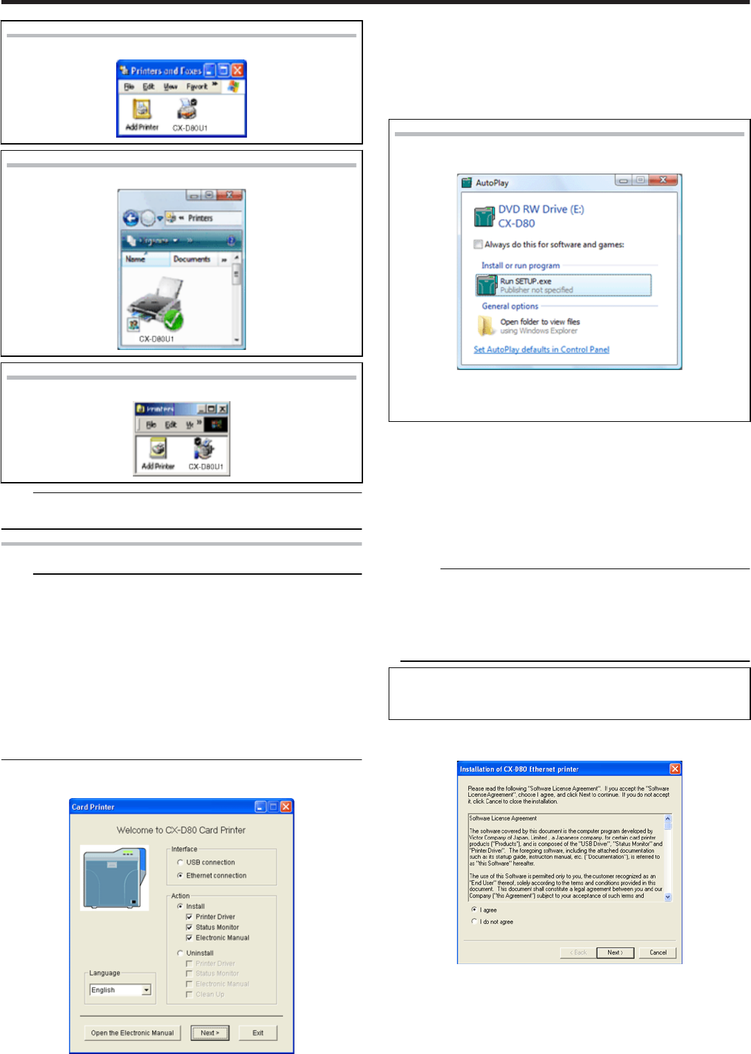
Start up Windows, and set the CD-ROM supplied into the PC.
●A [Card Printer] screen appears.
●If the CD-ROM of the PC is set to run automatically, the installer will be
executed automatically.
If the installer is not automatically initiated, double-click [Setup.exe] in
the CD-ROM folder.
●If you are not using the [Setup.exe] automatic execution program in the
CD-ROM, start the installer for the printer driver by double-clicking the
following file in the CD-ROM: “Japanese\USB_Soft\install.exe”.
Windows Vista
●
●
A [Auto play] screen appears.
●Clicking [Run SETUP.exe] displays the [User Account Contro]
screen.
●Clicking [Allow] displays the Card Printer Setup screen.
① Select the language to use from the pull-down menu.
●Selecting [English] switches the program to the English version.
●Selecting [Japanese] switches the program to the Japanese version.
② Select [Interface].
●Check to ensure that the [Ethernet connection] checkbox is selected.
③ Select [Action].
●Select [Install] to start installation. Select [Uninstall] to start uninstal-
lation.
④ Select the [Printer Driver] checkbox.
Memo:
●You can select the [Status Monitor] and [Online Manual]heckboxes
to install them simultaneously. Selecting all checkboxes starts instal-
lation in the order of the electronic manual, printer driver, followed by
status monitor.
●The same status monitor can be used for printers connected via USB
and Ethernet.
●Clicking [Open the instruction Manual] opens the electronic
manual.
●Clicking [Exit] ends the installation.
Click [Next].
●A [Installation of CX-D80 Ethernet printer] screen appears.
Read through the “Software License Agreement”.
●If you agree to the terms and conditions of the agreement, select the [I
agree] checkbox.
●If you do not agree, click [Cancel] to stop the installation.
Click [Next].
Setup
62
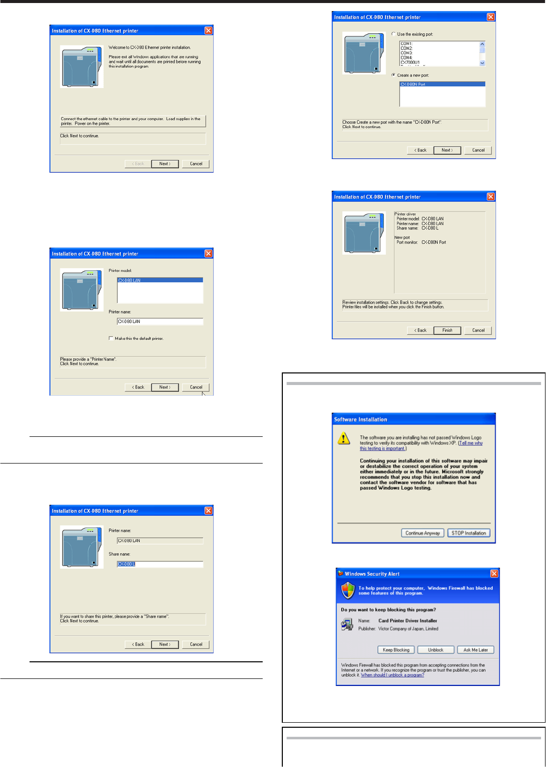
●A Start Installation screen appears.
Connect the printer and PC using a LAN cable.
Turn on the power of the printer.
Check the details, followed by clicking [Next].
●A Start Installation screen appears.
●The [Printer Model] and [Printer Name] setting screens appear.
① Select a printer model.
② Enter the printer name.
③ Select the [Make this the default printer] checkbox if necessary.
Memo:
●Doing so enables you to use it as a default printer after installation is
complete.
Click [Next].
●The Enter Shared Name screen appears.
●Enter the shared name when you are sharing a printer.
Memo:
●Select the [Make this the default printer] checkbox if necessary.
Click [Next].
●The Port Selection screen appears.
●Select [CXD80N Port] from [Create a new port].
Click [Next].
●An Installation Information confirmation screen appears.
Check the installation information, followed by clicking [Finish].
●To change the settings, click [Back].
Windows XP
●
●
A [Software Installation] screen appears.
① Click [Continue Anyway].
●A Windows warning screen appears.
② Click [Unblock].
●The program may not function properly if you click [Keep
Blocking].
Windows Vista
●A [Windows Important Security Warning] screen appears.
Setup
63
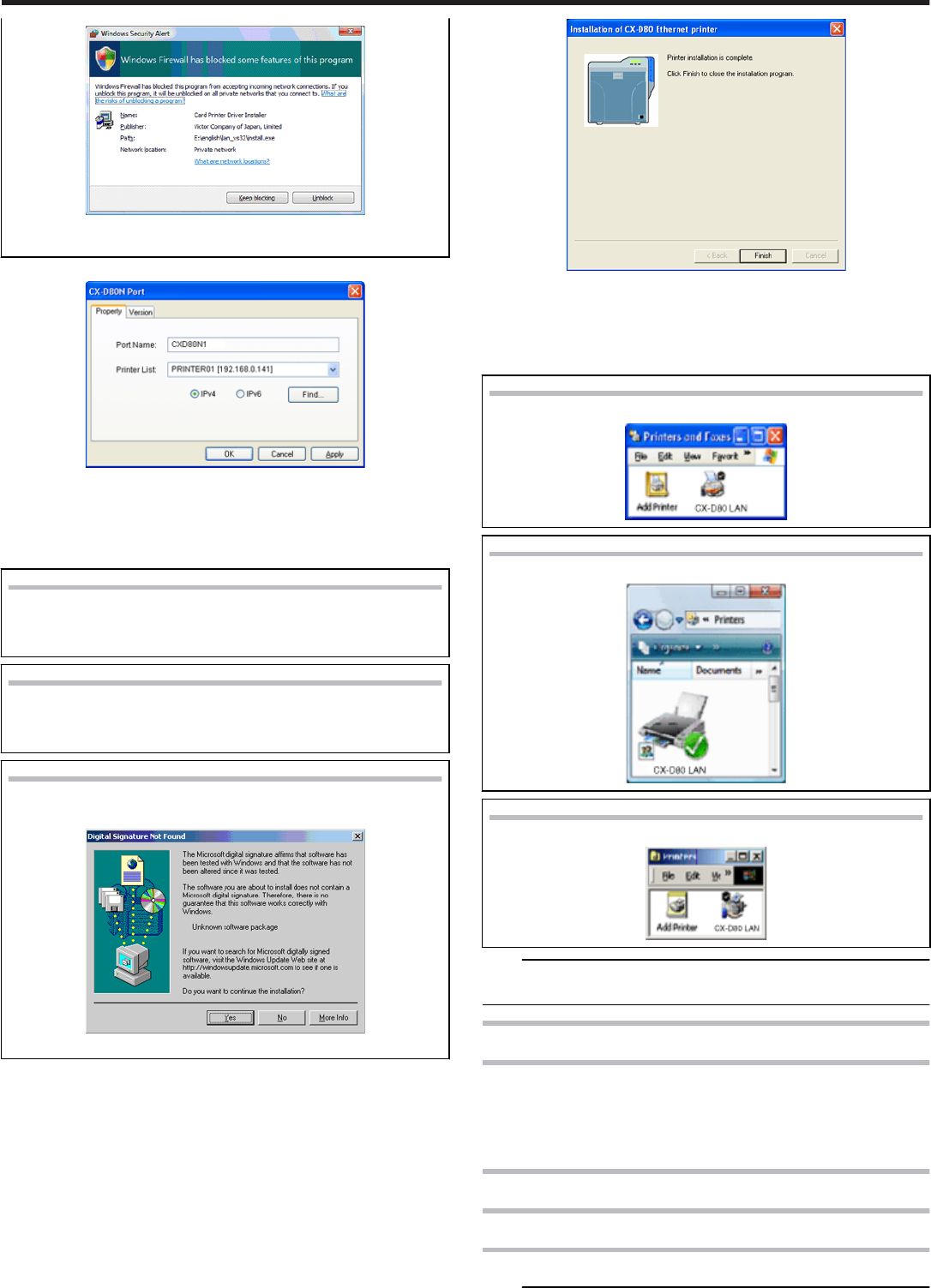
①
①
Click [Unblock].
●The program may not function properly if you click [Block].
●A [CXD80N Port] screen appears.
Select the [Property] tab.
① Select this printer from [Printer List].
② Enter the [Port Name].
Click [OK].
Windows XP
●A [Software Installation] screen appears.
① Click [Continue Anyway].
Windows Vista
●A Windows Security screen appears.
① Click on “Install this printer driver”.
Windows 2000
●A [Digital Signature Not Found] screen appears.
① Click [Yse].
●A Printer Installation Completed screen appears.
Click [Finish].
●Exits the installation program.
Open [Printer] in the [Control Panel].
●Check to ensure that the printer is added.
Windows XP
.
Windows Vista
.
Windows 2000 (Example)
.
Note:
●To delete a printer, execute “Uninstall printer driver” after restarting
Windows.
Update of Printer Driver
To update
delete the existing printer driver.
"Uninstall" (' page 70)
Re-install the printer driver.
Network Sharing of Printer
Network Sharing of Printer
Windows XP/ Windows 2000
Note:
Setup
64
●Check to ensure that you can access the PC to which the printer is
connected.
●Check also to ensure that the printer can be shared.
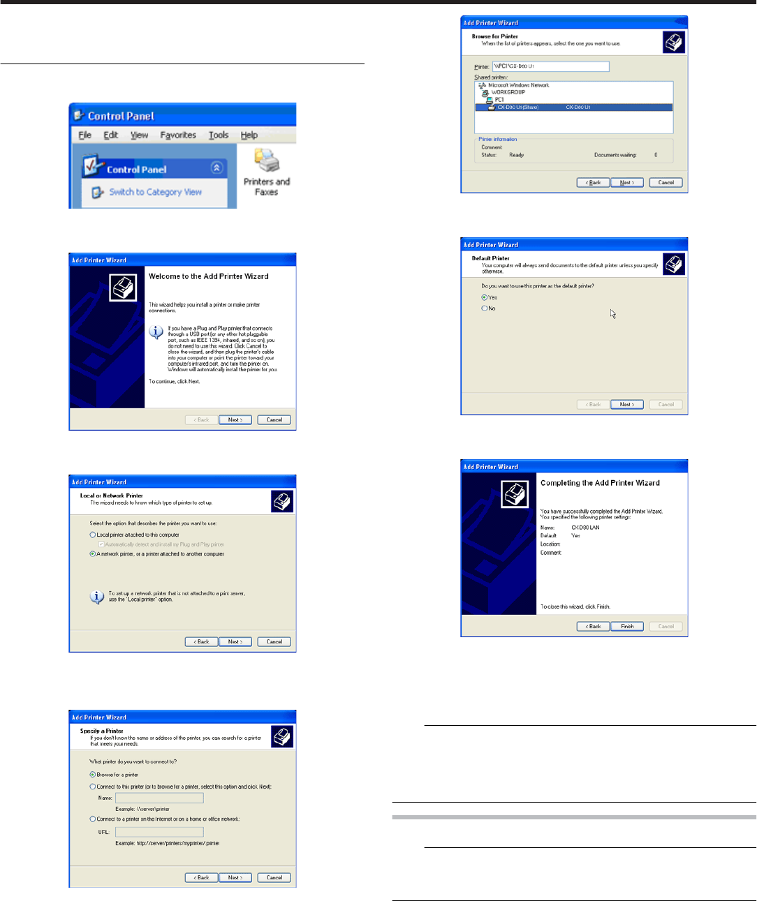
Open the printer in the [Control Panel].
●A [Printers and Faxes] screen appears.
Double-click [Add Printer].
●A [Add Printer Wizard] screen appears.
Click [Next].
●A Printer Type Selection screen appears.
Select “A network printer, or a printer connected to another computer”,
and click [Next].
●A [Specify Printer] screen appears.
Select [Browse for a printer], and click [Next].
●A [Browse for a printer] screen appears.
Select a printer from [Shared printers], and click [Next].
●A [Default Printer] screen appears.
Select [Yes] if necessary, and click [Next].
●A [Completing the Add Printer Wizard] screen appears.
Check the details, followed by clicking [Finish].
●Network sharing of the printer is complete.
Open the printer in the [Control Panel].
●Check to ensure that the printer is added.
Note:
●When the access authority of the computer is not proper, the printer
may not be able to perform printing even if installation of the printer
driver is completed.
Ensure that the access authority is proper according to the instructions
of the network administrator.
Windows Vista
Note:
●Check to ensure that you can access the PC to which the printer is
connected.
●Check also to ensure that the printer can be shared.
Open the printer in the [Control Panel].
●A [Printers] screen appears.
Setup
65
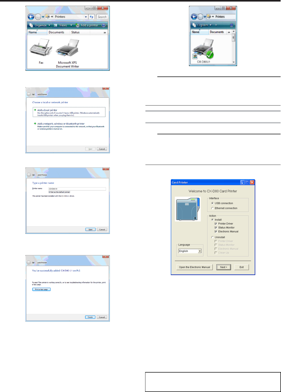
Click [Add a printer].
●A Printer Selection screen appears.
●Select [Add a network, wireless or Bluetooth printer], and click [Next].
●A [Add Printer] screen appears.
Select the [Set as the default printer] checkbox if necessary, and click
[Next].
●A Printer Addition Complete screen appears.
Check the details, followed by clicking [Finish].
●Network sharing of the printer is complete.
Open [Control Panel].
●Check to ensure that the selected printer is added to [Printers].
Note:
●When the access authority of the computer is not proper, the printer
may not be able to perform printing even if installation of the printer
driver is completed.
Ensure that the access authority is proper according to the instructions
of the network administrator.
Status Monitor
Install
Note:
●The same status monitor can be used for printers connected via USB
and Ethernet.
●Make sure that the status monitor is only installed once on a single PC.
●To continue using the status monitor after uninstalling the printer driver,
update the status monitor accordingly.
Start up Windows, and set the CD-ROM supplied into the PC.
●The Card Printer Setup screen appears.
●If the CD-ROM of the PC is set to run automatically, the installer will be
executed automatically.
If the installer is not automatically initiated, double-click [Setup.exe] in
the CD-ROM folder.
●If you are not using the [Setup.exe] automatic execution program in the
CD-ROM, start the installer for the status monitor by double-clicking the
following file in the CD-ROM:
“English\Software\STT_MON\install.exe”
① Select the language to use from the pull-down menu.
●Selecting [English] switches the program to the English version.
●Selecting [Japanese] switches the program to the Japanese version.
② Select [Interface].
●Select [USB connection] or [Ethernet connection].
③ Select [Action].
●Select [Install] to start installation. Select [Uninstall] to start uninstal-
lation.
④ Select the checkbox for the status monitor.
●
●
Clicking [Open the Electronic Manual] opens the electronic
manual.
●Clicking [Exit] ends the installation.
Click [Next].
Setup
66
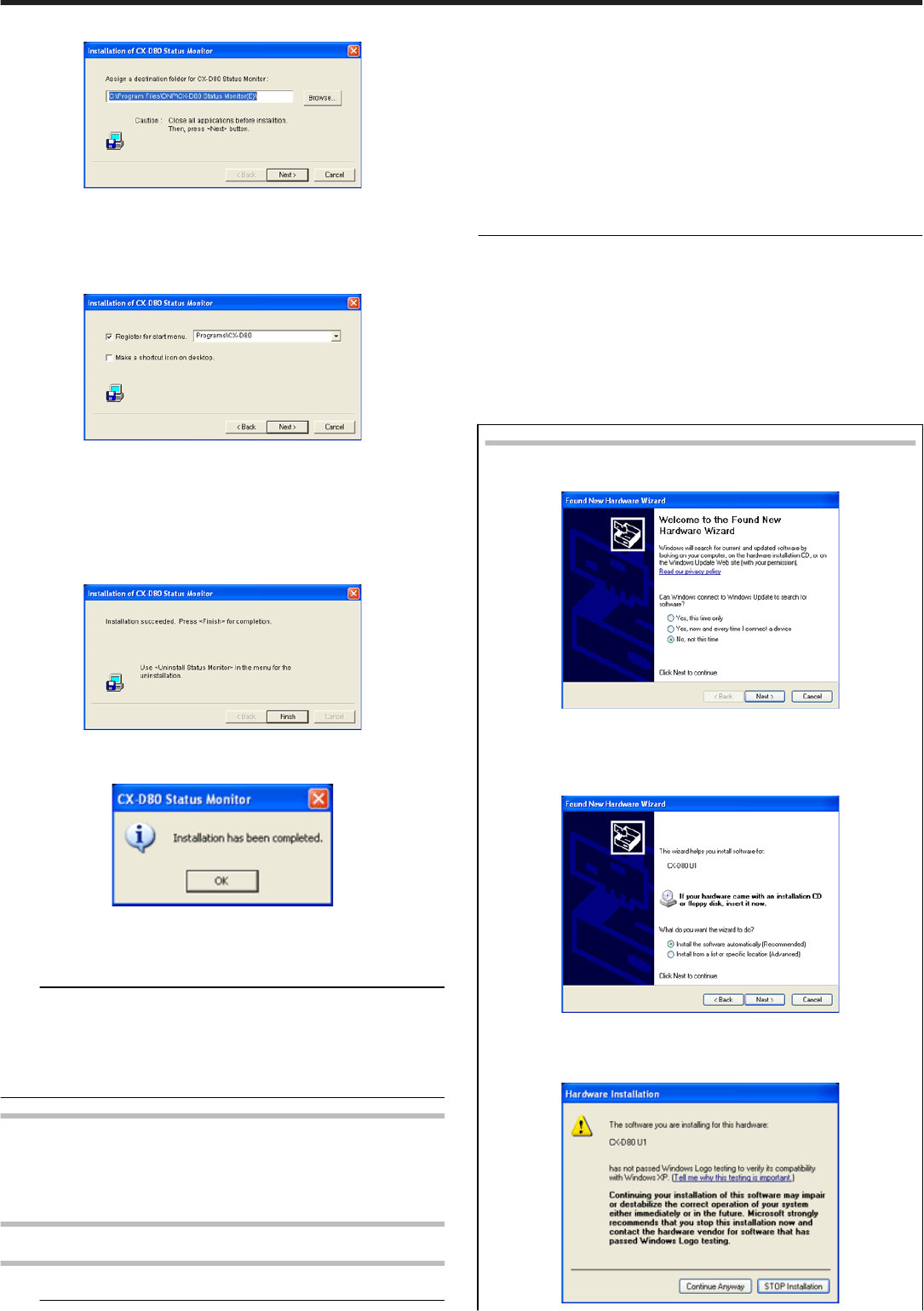
●A [Installation of CX-D80 Status Monitor] screen appears.
●To change the displayed installation destination, click [Browse] and
specify the destination folder.
Specify the destination to install the status monitor, followed by clicking
[Next].
●A Status Monitor Display Position selection screen appears.
① Select the [Register for start menu] checkbox.
●To alter the position of the displayed start menu, make a selection
from [Register to start menu].
② Select the [Make a shortcut icon on desktop] checkbox if necessary.
Click [Next].
●Installation starts.
●An Installation Completed screen appears.
Click [Finish].
●An Installation Completed confirmation screen appears.
Click [OK].
●Exits the installation program.
●You can now start the status monitor from [Start].
Note:
●The following error may occur.
Cause: The status monitor cannot run because the program cannot be
identified by Windows Vista.
Action: Select “Run as administrator...” to start the status monitor as a
user with administrator authority. Doing so enables the program to be
identified by Windows Vista, and subsequent error does not occur.
To update
Delete the status monitor.
"Uninstall" (' page 71)
Re-install the status monitor.
USB Driver
Installing the USB driver
Note:
●The USB driver is also installed while you are installing the printer driv-
er via USB connection.
●Install the USB driver additionally only when you want to set items oth-
er than the [Printer Name] on the [Printer Selection] screen of the sta-
tus monitor.
●Do not turn on the power of the printer until instruction asking you to do
so appears on the installer.
●Do not connect the printer to the USB until instruction asking you to do
so appears on the installer.
●You need to enable the USB hub before connecting the printer via this
hub. Do not connect the printer to the USB hub until instruction asking
you to do so appears.
Start up Windows.
Set the CD-ROM supplied into the PC.
(Windows XP and Windows 2000)
(For Windows Vista, do not set the CD-ROM yet at this point of time.)
●The “Setup.exe” automatic execution program in the CD-ROM is not
used. Exit this program.
Connect the PC and printer using a USB cable, and turn on the power
of the printer.
●The printer is automatically detected by the PC.
Windows XP
●
●
A [Found New Hardware Wizard screen appears.
Click [No, not this time].
●Connection is improper if this screen does not appear. Make
sure that the connection is properly established.
●An Installation Method selection screen appears.
Select the [Install the software automatically(Recommended)]
checkbox, and click [Next].
●A [Hardware Installation] screen appears.
Setup
67
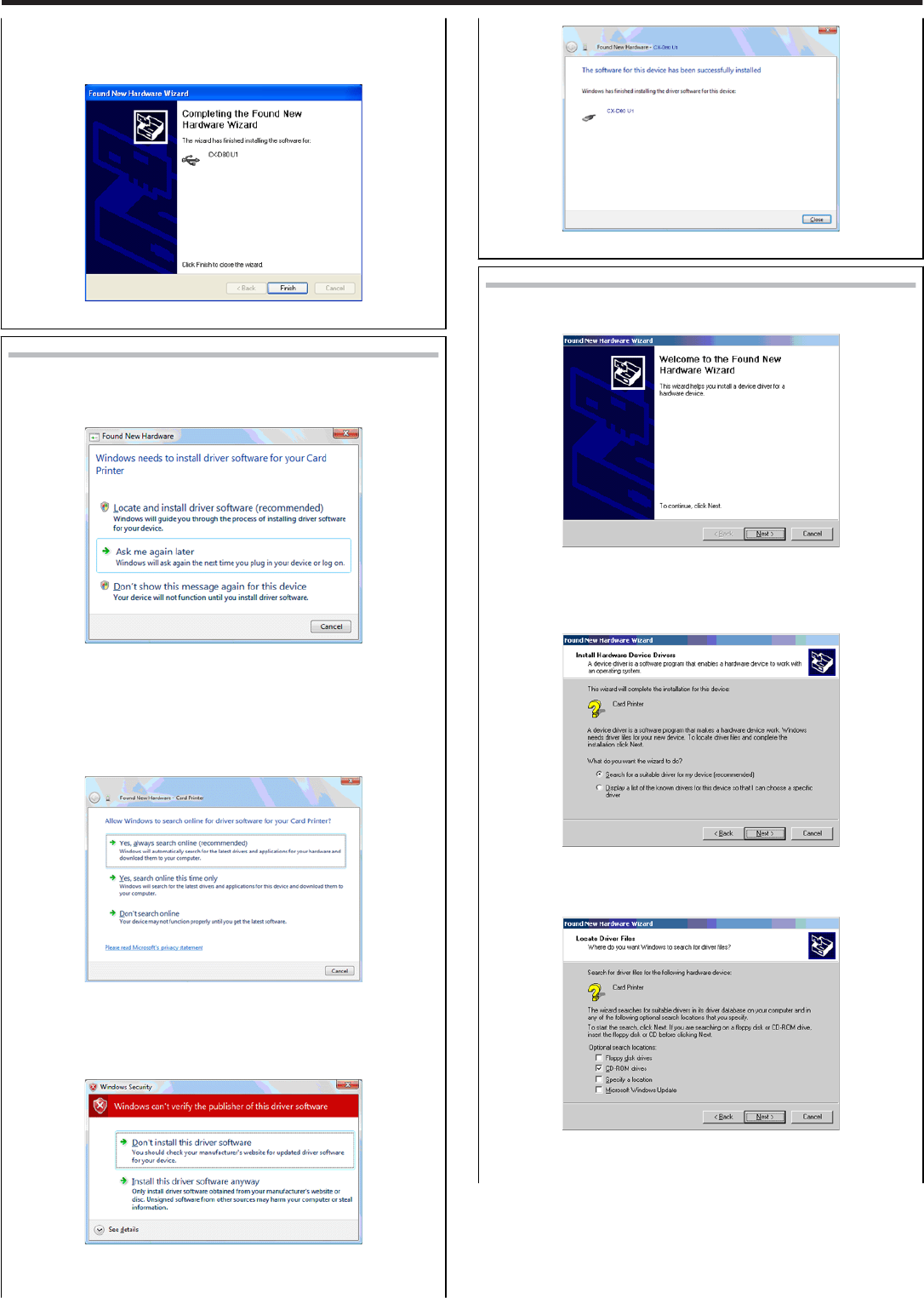
Click [Continue Anyway].
●
●
A [Completing the Found New Hardware Wizard] screen ap-
pears.
●Installation of the USB driver is complete.
Windows Vista
●A [Found New Hardware] screen appears.
Click on [Locate and install driver software (recommended)].
●Connection is improper if this screen does not appear. Make
sure that the connection is properly established.
●A [User Account Control] screen appears.
Click [Continue].
●A [Found New Hardware] screen appears.
Click [Yes, always search online (recommended)].
●A screen appears, prompting you to insert the disc.
Set the CD-ROM into the PC.
●A [Windows Security] screen appears.
Click on [Install this driver software].
●An Installation Completed screen appears.
Click [Close].
●Installation of the USB driver is complete.
Windows 2000
●A [Found New Hardware Wizard] screen appears.
Click [Next].
●Connection is improper if this screen does not appear. Make
sure that the connection is properly established.
●A Search Method selection screen appears.
Select the [Search for a suitable driver for my device(recommen-
ded)] checkbox, and click [Next].
●A [Locate Driver Files] screen appears.
Select the [CD-ROM drives] checkbox, and click [Next].
●A [Driver Files Search Results] screen appears.
Setup
68
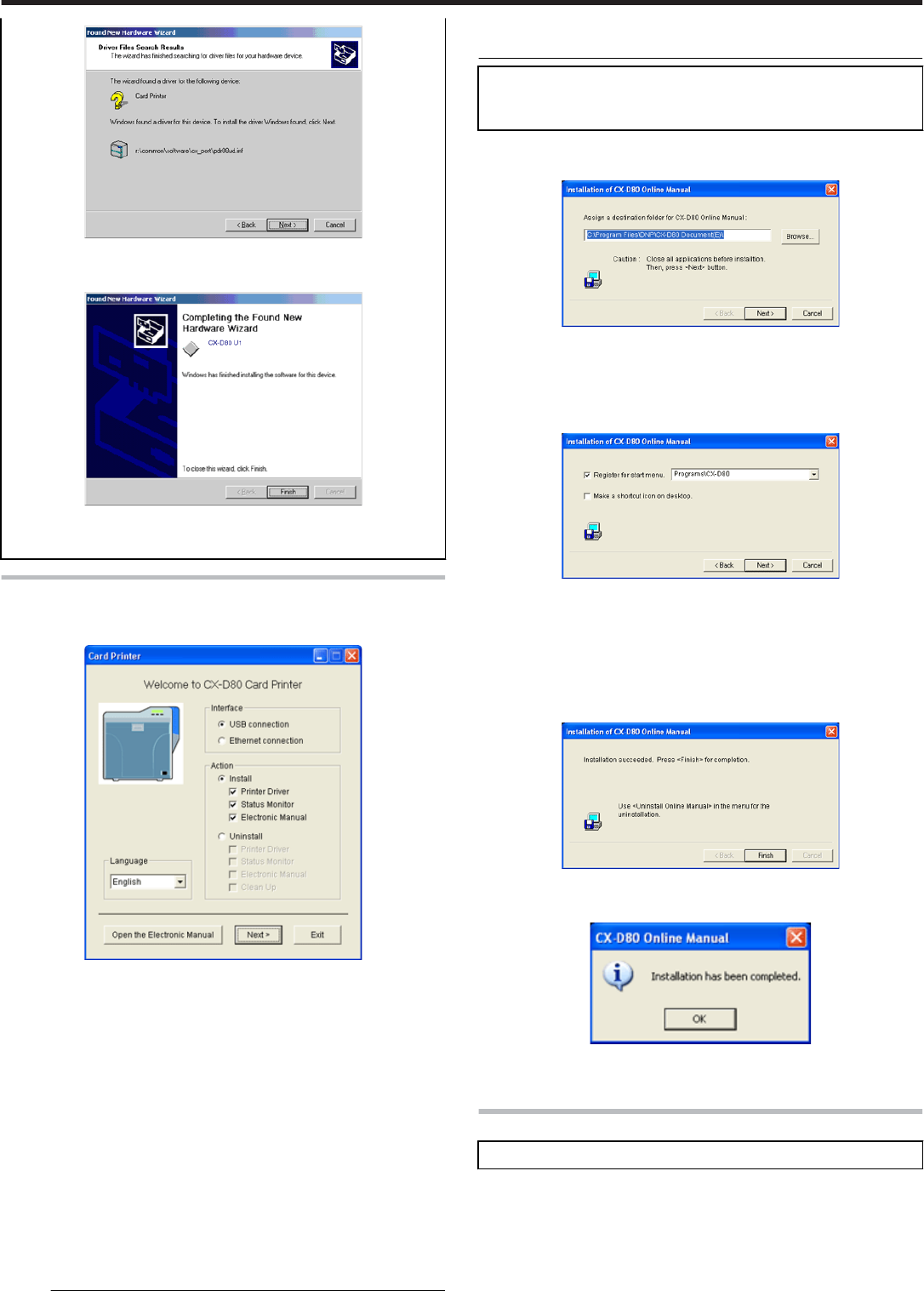
Click [Next].
●
●
A [Found New Hardware Wizard] screen appears.
Click [Finish].
●Installation of the USB driver is complete.
Electronic Manual
Start up Windows, and set the CD-ROM supplied into the PC.
●The Card Printer Setup screen appears.
●If the CD-ROM of the PC is set to run automatically, the installer will be
executed automatically.
If the installer is not automatically initiated, double-click [Setup.exe] in
the CD-ROM folder.
●If you are not using the [Setup.exe] automatic execution program in the
CD-ROM, start the installer for the [Electronic Manual] by double-click-
ing the following file in the CD-ROM:
“English\Software\STT_MON\install.exe”
① Select the language to use from the pull-down menu.
●Selecting [English] switches the program to the English version.
●Selecting [Japanese] switches the program to the Japanese version.
② Select [Interface].
●Select [USB connection] or [Ethernet connection].
③ Select [Action].
●Select [Install] to start installation. Select [Uninstall] to start uninstal-
lation.
Select the checkbox for the electronic manual.
Memo:
●You can select the [Printer Driver] and [Status Monitor] checkboxes to
install them simultaneously.
●Clicking [Open the Electronic Manual] opens the electronic
manual.
●Clicking [Exit] ends the installation.
Click [Next].
●An [Electronic Manual Installation] screen appears.
●To change the displayed installation destination, click [Browse] and
specify the destination folder.
Specify the destination to install the status monitor, followed by clicking
[Next].
●An Electronic Manual Display Position selection screen appears.
① Select the [Register for start menu] checkbox.
●To alter the position of the displayed start menu, make a selection
from [Register to start menu].
② Select the [Make a shortcut icon on desktop] checkbox if necessary.
Click [Next.
●Installation starts.
●An Installation Completed screen appears.
Click [Finish].
●An Installation Completed confirmation screen appears.
Click [OK].
●Exits the installer.
Uninstall
●Administrator authority is required to uninstall the program.
●"Printer Driver" ' page 70
●"Status Monitor" ' page 71
Setup
69
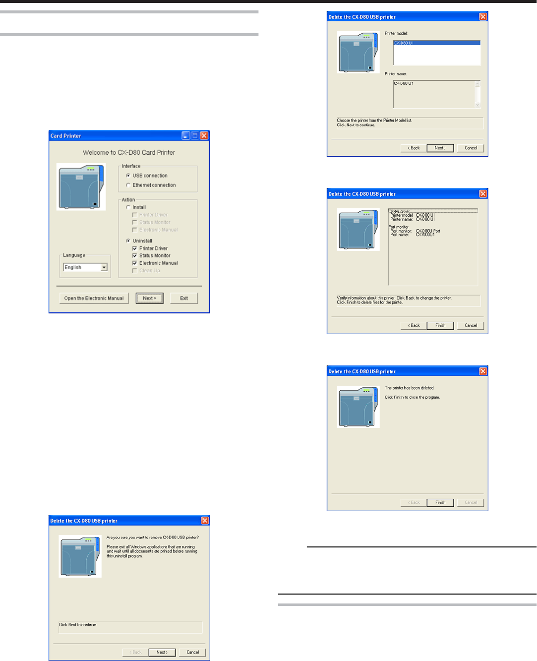
Printer Driver
USB connection
Connect the PC and printer using a USB cable, and turn on the power
of the printer.
●Check to ensure that the printer connected via USB is recognized on
the PC. If the USB connection is not recognized, the USB driver cannot
be correctly deleted.
Start up Windows, and set the CD-ROM supplied into the PC.
●The Card Printer Setup screen appears.
●If the CD-ROM of the PC is set to run automatically, the installer will be
executed automatically.
If the installer is not automatically initiated, double-click [Setup.exe] in
the CD-ROM folder.
●If you are not using the [Setup.exe] automatic execution program in the
CD-ROM, start the installer for the printer driver by double-clicking the
following file in the CD-ROM: “English\USB_Soft\install.exe”.
Select [Interface].
●Check to ensure that the [USB connection] checkbox is selected.
Select [Action].
●Select [Uninstall].
Select the [Printer Driver] checkbox.
●You can select the [Electronic Manual] checkbox to install it simultane-
ously. Selecting all checkboxes starts uninstallation in the order of the
[Printer Driver] followed by [Electronic Manual].
Click [Next].
●A [Delete the CX-D80 USB printer]screen appears.
Check the details, followed by clicking [Next].
●A Printer Model selection screen appears.
Select the printer to uninstall, and click [Next].
●An Uninstallation Information confirmation screen appears.
Check the details, followed by clicking [Finish].
●An Uninstallation Completed screen appears.
Click [Finish].
●Exits uninstallation.
Memo:
●Uninstall the USB printer drivers accordingly for each printer unit num-
ber.
●To re-install a printer driver, perform the installation procedures after
restarting Windows.
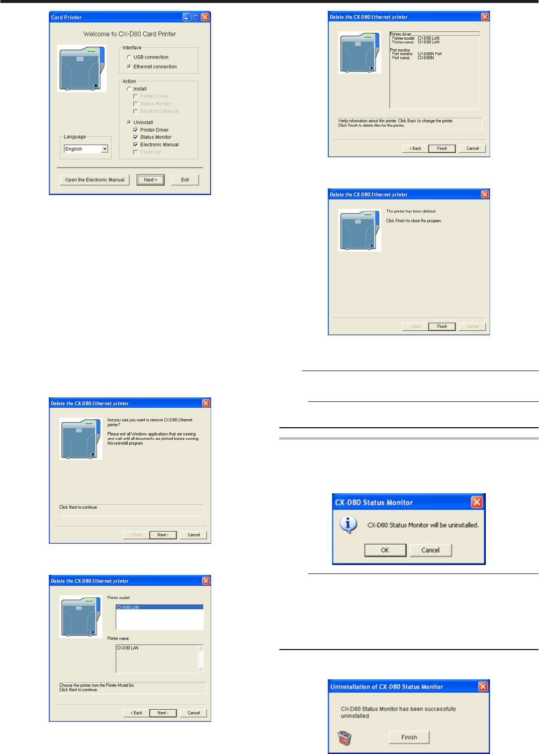
Ethernet (LAN) Connection
Connect the PC and printer using a LAN cable, and turn on the power
of the printer.
●Do not connect a USB cable to the printer.
Start up Windows, and set the CD-ROM supplied into the PC.
●A [Card Printer] screen appears.
Setup
70
●If you are not using the [Setup.exe] automatic execution program in the
CD-ROM, start the uninstaller for the printer driver by double-clicking
the following file in the CD-ROM:
“English\LAN_Soft\uninstall.exe”
●To use the “SETUP.exe” automatic execution program, refer to the
chapter on “Installer (Automatic Execution Program)”. You can start the
uninstaller for the printer driver using the automatic execution program.
Select [Interface].
●Check to ensure that the [Ethernet connection] checkbox is selected.
Select [Action].
●Select [Uninstall].
Select the [Printer Driver] checkbox.
●You can select the [Electronic Manual] checkbox to install it simultane-
ously. Selecting all checkboxes starts uninstallation in the order of the
[Printer Driver] followed by [Electronic Manual].
Click [Next].
●A [Delete the CX-D80 Ethernet printer] screen appears.
Check the details, followed by clicking [Next].
●A Printer Model selection screen appears
Select the printer to uninstall, and click [Next].
●An Uninstallation Information confirmation screen appears.
Check the details, followed by clicking [Finish].
●An Uninstallation Completed screen appears.
Click [Finish].
●Exits uninstallation.
Note:
●In the case where multiple Ethernet (LAN) printer drivers are installed,
the uninstaller deletes all of these printer drivers.
Memo:
●To re-install a printer driver, perform the installation procedures after
restarting Windows.
Status Monitor
Exit the status monitor.
Select [Uninstall] from [Start].
●A [Status Monitor] screen appears.
Memo:
●If the “Register to start menu” checkbox is not selected during installa-
tion of the status monitor, delete using [Add/Delete Programs] in [Con-
trol Panel].
●To use the “Setup.exe” automatic execution program, refer to the chap-
ter on “Installer (Automatic Execution Program)”. You can start the un-
installer for the status monitor using the automatic execution program.
"SETUP.exe" (' page 66)
Click [OK].
●A [Status Monitor Deletion] screen appears.
Setup
71
Click [Finish].
●Exits the program.
IP Sec
Certificate Authentication
Setting Flow
① Request the “PC Certificate” to the certification authority.
② The “PC Certificate” and “Certification Authority Certificate” are is-
sued by the certification authority. Install these on the PC.
③ Request the “Printer Certificate” to the certification authority.
④ The “Printer Certificate” and “Certification Authority Certificate” are
issued by the certification authority. Install these on the PC.
⑤ Export the “Printer Certificate” and save it in a file.
⑥ Export the “Certification Authority Certificate” and save it in a file.
⑦ Connect the printer via USB, and download the “Printer Certificate”
using the status monitor.
⑧ Connect the printer via USB, and download the “Certification Author-
ity Certificate” using the status monitor.
⑨ Connect the printer via the network (Ethernet) and enable IP Sec (IP
Security) on the PC to start IP Sec communication.
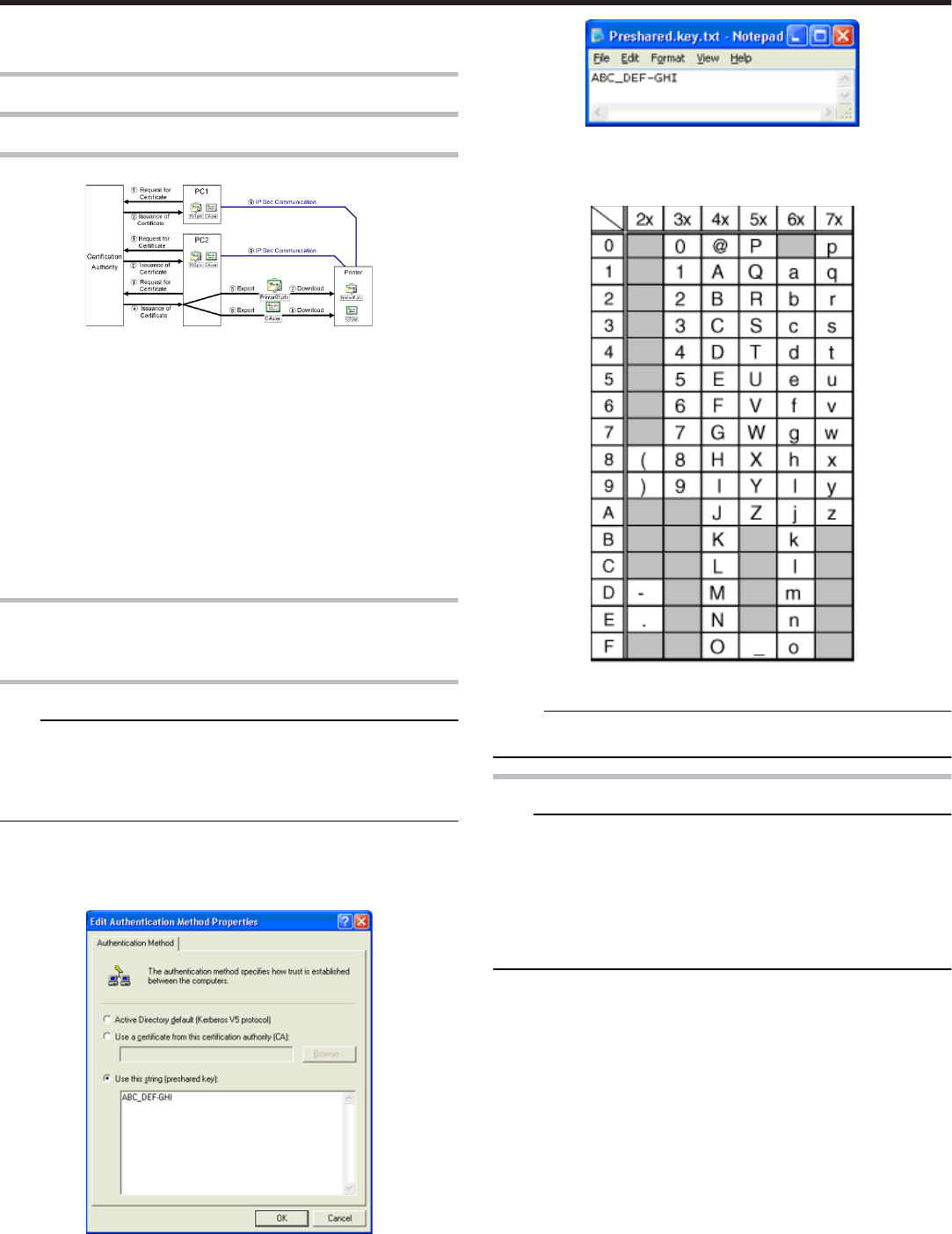
Preshared Key Authentication
●Connect the printer via USB, and download the “Preshared Key File”
using the status monitor.
Preshared Key File
Note:
●Operate IP Sec (IP Security) on Windows® by following the instructions
of the network administrator for the location where the printer is instal-
led.
●Manage the “Preshared Key File” according to the instructions of the
network administrator.
Start “IP Security Policy Management” under the MMC (Management
Console).
Open the “Edit Authentication Method Properties” of the policy for
which the preshared key is to be used.
Make use of applications such as Windows® “Notepad” to create a
preshared key string, and save it as a file with the extension “.key”.
●After saving, this file will be downloaded as the “Preshared Key File”
when setting “Preshared Key Authentication” using the status monitor.
●ASCII characters that can be used for the preshared key of the printer
are as follows. The maximum length is 255 characters.
Memo:
●For “Preshared Key Authentication” procedures on the printer, refer to
the status monitor instruction manual.
Printer Certificate File
Note:
●Operate IP Sec (IP Security) on Windows® by following the instructions
of the network administrator for the location where the printer is instal-
led.
●Manage the “Printer Certificate File” according to the instructions of the
network administrator.
●There is an expiration date for the “Printer Certificate”. IP Sec commu-
nication may fail or may not be encrypted successfully if an expired
certificate is used.
Obtain the printer certificate from the certification authority, and install
it on the PC’s “Certificate (Local Computer)”
●Obtain the printer certificate as an “exportable key”.
Start “Certificate (Local Computer)” under the MMC (Management
Console)
Open the Personal Store to export the printer certificate
●The format is “PKCS#12”. Make sure that you specify a password. The
file is saved with the extension “.pfx”.
Setup
72
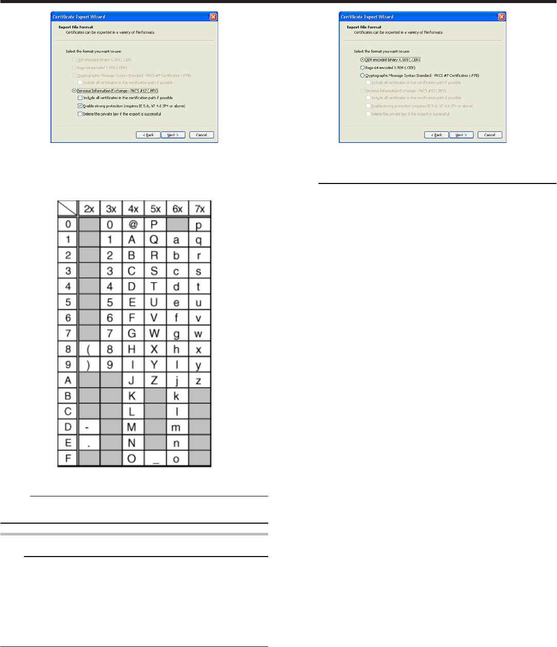
●After saving, this file will be downloaded as the “Printer Certificate File”
when setting “Certificate Authentication” using the status monitor.
●ASCII characters that can be used for the password of the printer certif-
icate of the printer are as follows. The maximum length is 255 charac-
ters.
Memo:
●For “Printer Certificate Authentication” procedures on the printer, refer
to the status monitor instruction manual.
Certification Authority Certificate File
Note:
●Operate IP Sec (IP Security) on Windows® by following the instructions
of the network administrator for the location where the printer is instal-
led.
●There is an expiration date for the “Certification Authority Certificate”.
IP Sec communication may fail or may not be encrypted successfully if
an expired certificate is used.
●Manage the “Certification Authority Certificate File” according to the in-
structions of the network administrator.
Start “Certificate (Local Computer)” under the MMC (Management
Console)
Open the Certification Authorities Store, and export the same “Certifi-
cation Authority Certificate” as the printer certificate
●The format is “DER encoded binary X509”. The file is saved with the
extension “.cer”.
●After saving, this file will be downloaded as the “Certification Authority
Certificate File” when setting “Certificate Authentication” using the sta-
tus monitor.
Memo:
●For “Printer Certificate Authentication” procedures on the printer, refer
to the status monitor instruction manual.
Setup
73
Printer Driver Settings
Setting Example
"[Setup]Tab Sheet" ' page 74
"[Print]Tab Sheet" ' page 74
●"[Printing area]Dialog" ' page 75
●"[Color]Dialog" ' page 75
●"[Look up table]Dialog" ' page 75
●"[Dither]Dialog" ' page 76
●"[UV ink]Dialog" ' page 76
●"[Printer settings]Dialog" ' page 78
"[Encode]Tab Sheet" ' page 79
"[Configuration]Tab Sheet" ' page 79
"[Version]Tab Sheet" ' page 80
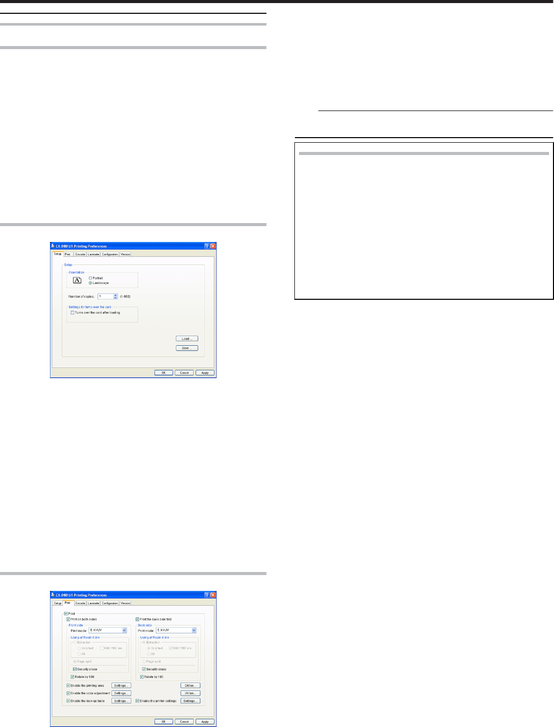
[Setup]Tab Sheet
Orientation
●Settings for printing orientation.
① Portrait
●Print with the shorter edge of the card on top.
② Landscape
●Print with the longer edge of the card on top.
Number of copies
●The number of copies to issue. Enter a number up to 999.
Settings for turns over the card
●Settings for turns over the card.
Load
●Loads setting information from a specified file.
Save
●Saves setting information to a specified file.
[Print]Tab Sheet
Print
●Executes printing.
Print on both sides
●Prints both sides of the card.
Print the back side first
●Prints the image on the back side first when printing on both sides of
the card.
Front side/Back side
●Front side: Print settings for the front side of the card.
●Back side: Print settings for the back side of the card.
① Print mode
●Ink list. Specify the ink to use for printing.
Note:
●Print error occurs if an ink that is not mounted to the printer is selec-
ted.
Setting values
●
●
1. YMC:
Prints using the YMC ink.
●2. K:
Prints using the Resin K ink.
●3. YMCK:
Prints using the YMC ink and Resin K ink.
●5. K+UV:
Prints using the Resin K ink. Prints the setting data in the [UV
ink] dialog using the UV ink.
●6. YMCK+UV:
Prints using the YMC ink and Resin K ink. Prints the setting
data in the [UV ink] dialog using the UV ink.
② Resin K ink
●For specifying the component to print using the Resin K ink.
③ Extraction
●Prints the black color component on each page using the Resin K
ink.
④ Text
●Prints only the black color text using the Resin K ink.
⑤ All
●Prints all black color components using the Resin K ink.
⑥ With YMC ink
●Prints the background of the specified black color component using
the YMC ink.
⑦ Page split
●Prints all components on a specific page using the Resin K ink.
⑧ Security erase
●Enables the Resin K security feature.
⑨ Rotate by 180
●Prints the page upside down.
Settings…
① Enable the printing area
●Prints in the specified area. Set a value in the [Printing Area] dialog.
② [Update]
●Opens the [Printing Area] dialog.
③ Enable the color adjustment
●Adjusts the color. Set a value in the [Color Adjustment] dialog.
④ [Update]
●Opens the [Color Adjustment] dialog.
⑤ Enable the look-up table
●Uses the look-up table. Set a value in the [Look-up Table] dialog.
⑥ [Update]
●Opens the [Look-up Table] dialog.
⑦ [Dither]
●For specifying settings related to dithering.
⑧ [UV ink]
●For specifying settings related to UV ink print data.
⑨ Enable the printer settings
●For specifying settings of the printer unit. Set a value in the [Printer
Settings] dialog.
⑩ [Update]
●Opens the [Printer Settings] dialog.
●"[Printing area]Dialog" ' page 75
Setup
74
●"[Color]Dialog" ' page 75
●"[Look up table]Dialog" ' page 75
●"[Dither]Dialog" ' page 76
●"[UV ink]Dialog" ' page 76
●"[Printer settings]Dialog" ' page 78
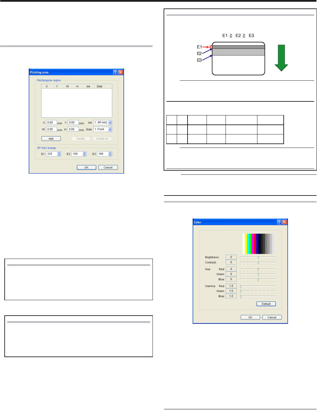
[Printing area]Dialog
●Settings related to the printing area using Special ink 2 or areas not to
be printed using all YMCKUV inks.
Area
●Printing area information.
① X
●Start X-coordinate of the printing area by millimeter.
② Y
●Start Y-coordinate of the printing area by millimeter.
③ W
●Width of the printing area by millimeter.
④ H
●Height of the printing area by millimeter.
⑤ Ink
●Ink valid for the printing area.
Setting values
●
●
1. SP-Ink2:
Area to print using the peel off ink.
●2. YMCK:
Area not to be printed using all YMCKUV inks.
⑥ Side
●The side of the card for which the printing area is valid.
Setting values
●1. Front:
Front side
●2. Back:
Back side
[Add]
●Registers the input data. You can enter up to 8 input data.
[Delete]
●Deletes the information selected in the list.
[Delete All]
●Deletes all registered information.
SP-Ink2 energy
●Print density of the Special ink 2.
① E1: 225
② E2: 160
③ E3: 160
Setting Values
●Each of the set values must satisfy the following requirements.
Note:
●Special ink 2 (SP-Ink2) can be used by a printer with PO (peel
off) print function. Please consult our authorized dealers for de-
tails.
●The following values are recommendation when you print with
PO (peel off) function on the magnetic stripe area of the card.
X Y W H Ink Side
0 0 87.46 13.89 1 (SP-Ink2) 1 (Front)
0 0 87.46 15.92 2 (YMCK) 1 (Front)
Note:
●The input value of the text box may differ from the value of the
“Printing area information” portion by an accidental error in cal-
culation.
Memo:
●The printing starting position that is set with application software may
not match with the above mentioned X=0 and Y=0.
About 1 mm portion is not printed from the end of a picture to a card.
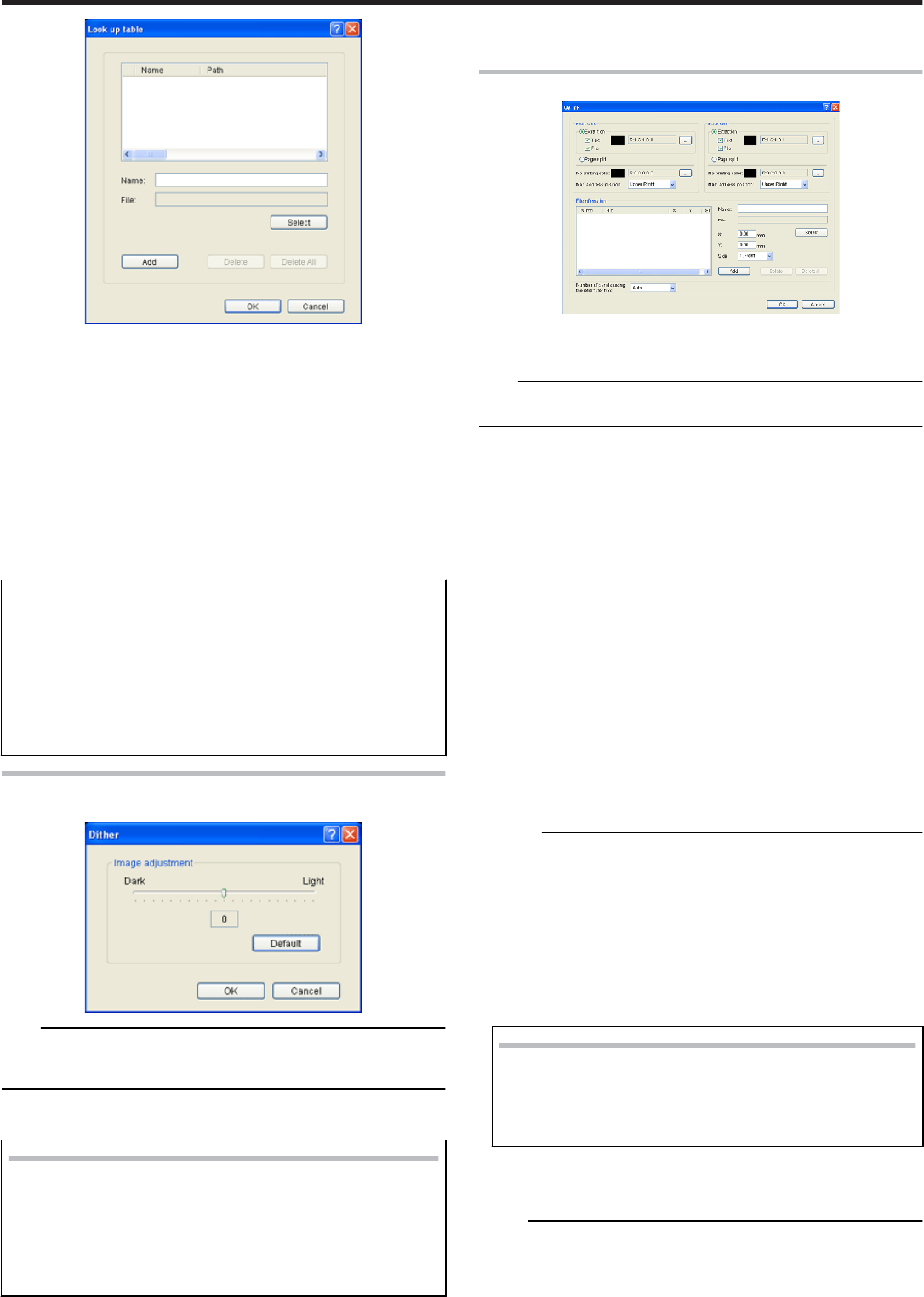
[Color]Dialog
●Settings related to color adjustment.
Brightness
●Brightness level.
Contrast
●Contrast level.
Hue
●Hue level.
Gamma
●Gamma level.
Default
●Restores the settings to the default values.
[Look up table]Dialog
●Settings related to the look-up table.
Setup
75
Name
●Registered name of the look-up table file. You can enter a name up to
30 characters.
File
●Look-up table file. Click the [Select] button to select a file.
[Add]
●Registers the input data. You can enter up to 16 input data.
[Delete]
●Deletes the information selected in the list.
[Delete All]
●Deletes all registered information.
●
●
Structure of the file
●Data format of the file is CSV (Comma Separated Values).
●Delimiter character is comma (ASCII character code: 0x2c) or LF
(Line Feed = ASCII character code: 0x0A).
●There is a total of 1024 fields. This is comprised of four planes,
each containing 256 fields.
●The planes are arranged in the order of yellow, magenta, cyan,
and black colors.
●The value of each field ranges between 0 and 255.
[Dither]Dialog
●Settings related to dithering.
Note:
●This setting is valid only when the [Mode] item inside the [Print] tab is
specified as 2. K or 5. K+UV, and when Page split is selected for [Res-
in K ink].
Image adjustment
●Image adjustment value.
Setting values
●Dark:
Darkens the printed image after dithering.
●0:
Default value.
●Light:
Brightens the printed image after dithering.
[Default]
●Restores the settings to the default values.
[UV ink]Dialog
●Settings related to the data to be printed using the UV ink. Settings of
“MAC address position” and “Number of panels using the retransfer
film” are in this section.
Note:
●This setting is valid only when the [Mode] item of the [Print] tab is
specified as [5. K+UV] or [6. YMCK+UV].
Front side/Back side
●Settings for the front side of the card.
●Settings for the back side of the card.
① Extraction
●Prints the following color component on each page using the UV ink.
"About the priority of printing data" (' page 77)
② Text
●Prints the text of a specified color using the UV ink with maximum
density.
●White and black colors cannot be selected.
③ File
●Prints the picture files registered by list of “File information” using the
UV ink.
④ Page split
●Prints all components on a specific page using the UV ink with 256
gradation. Page split is divided in order of YMC ink, Resin K ink and
UV ink.
"The page number of the printing document and setup of Page split" (
' page 77)
⑤ No printing color
●Selected color is not printed using the UV ink.
Memo:
●The background of UV ink picture is specified here. Paint over the
background of picture by a specific color using graphic software etc.
If background color is the same as part of the picture, it will not be
printed. So please select background color carefully.
●The color selected here does not influence the color specified by [Ex-
traction]- [Text]. Even when the same color is selected, the text of
the color is printed.
⑥ MAC address position
●The network (Ethernet) MAC address of the printer is printed at the
following specified position using the UV ink.
Setting values
●Upper Right:
Upper right position
●Lower Left:
Lower left position
"About the MAC address position" (' page 77)
File Information
●Settings related to the printing picture file using the UV ink.
Memo:
●This setting is valid when the [Extraction]- [File] is specified at front side
or back side.
① Name
Setup
76
●Registered name of the picture file. You can enter a name up to 30
characters.
② File
●Picture file. Click the [Select] button to select a file.
"File type of Windows® Bitmap (*.BMP)" (' page 78)
③ X
●Start X-coordinate of the printing picture file by millimeter.
When [Landscape] at [Orientation] inside [Setup] tab is set, the value
is 0.00 to 87.4. When [Portrait] is set, the value is 0.00 to 55.9. The
data which is outside of the printing area is not printed.
④ Y
●Start Y-coordinate of the printing picture file by millimeter.
When [Landscape] at [Orientation] inside [Setup] tab is set, the value
is 0.00 to 55.9. When [Portrait] is set, the value is 0.00 to 87.4. The
data which is outside of the printing area is not printed.
⑤ Side
●The side of the card for which the printing area is valid.
Setting values
●
●
1. Front:
Front side
●2. Back:
Back side
[Add]
●Registers the input data. You can enter up to 8 input data.
[Delete]
●Deletes the information selected in the list.
[Delete All]
●Deletes all registered information.
Number of panels using the retransfer film
●Number of panels using the retransfer film.
Setting values
●Auto:
When the data of other ink does not overlap with the printing
point of UV ink, it prints automatically using the retransfer film
of 1 panel.
●1 panel:
Always prints using the retransfer film of 1 panel. However,
when the data of other ink overlaps with the printing point of UV
ink, the data of other ink is adjusted.
●2 panels:
Always prints using the retransfer film of 2 panel.
"The number of panels using the retransfer film at the time of printing" (
' page 78)
About the priority of printing data
●A extracted text has the priority higher than a picture file, and is always
printed on the top surface.
●The picture file is processed in order of registration. When the printing
range overlaps, the data of the picture file registered later overwrites
former data.
The page number of the printing document and setup of
[Page split]
① setup of [Page split]
② Resin K ink
③ UV ink
④ Front
⑤ Back
⑥ The page number of the printing document
⑦ This ink is printed on the front side.
⑧ This ink is printed on the back side.
●When the [Page split] is not set, extracts the data of UV ink from the
data of YMC ink, or uses the picture file for UV ink.
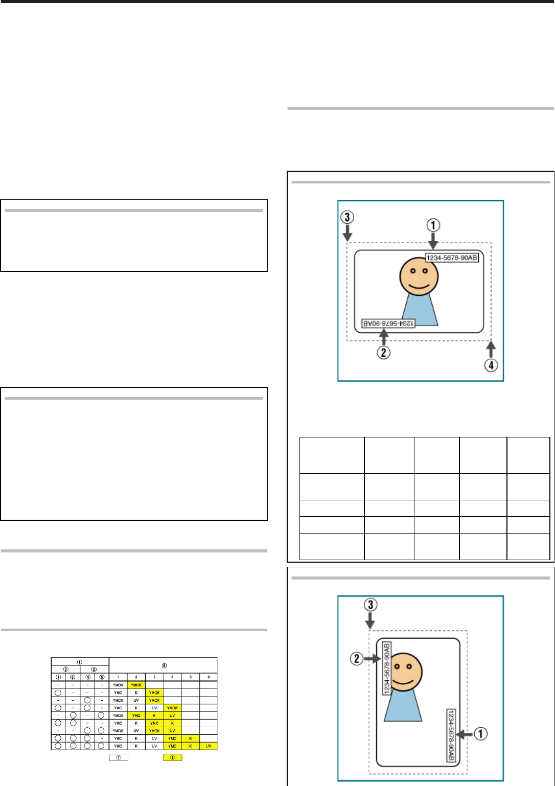
About the MAC address position
●In the case of UV print, the printer always prints the MAC address.
●The position of MAC address can be set up separately to front-side and
back-side by the printer driver. The following two position can be chos-
en.
[Landscape] Orientation
.
① The position of MAC address at [Upper Right].
② The position of MAC address at [Lower Left].
③ (X=0, Y=0)
④ (About X=87.5 mm, About Y=56.0 mm)
(X=1035pixel, Y=663pixel)
The position
of MAC ad-
dress
X Y Width Height
Upper Right 64.69
mm
0.06 in 0.77 in 0.11 in
Upper Right 764 pixel 18 pixel 230 pixel 34 pixel
Lower Left 0.14 in 2.04 in 0.77 in 0.11 in
Lower Left 42 pixel 611 pix-
el
230 pixel 34 pixel
[Portrait] at Orientation
.
Setup
77
①
①
The position of MAC address at [Upper Right].
② The position of MAC address at [Lower Left].
③ (X=0, Y=0)
The position
of MAC ad-
dress
X Y Width Height
Upper Right 2.04 in 64.69
mm
0.11 in 0.77 in
Upper Right 612 pix-
el
764 pixel 34 pixel 230 pixel
Lower Left 0.06 in 0.14 in 0.11 in 0.77 in
Lower Left 19 pixel 42 pixel 34 pixel 230 pixel
●The above setting of MAC address is always effective regardless of the
printer unit setting.
Indicated data shows the relative position from the starting point of the
picture. So actual printing position on the card will include some differ-
ence from the above mentioned indicated data.
Memo:
●The printing starting position that is set with application software may
not match with the above mentioned X=0 and Y=0.
About 1 mm portion is not printed from the end of a picture to a card.
The following file type of Windows® Bitmap (*.BMP) are sup-
ported.
Monochrome/Black & white
●Bit(s): 1
●Normally, the white color is printed using the UV ink with maxi-
mum density.
When the white color is selected at the [No printing color], the
black color is printed using the UV ink with maximum density.
2 Color
●Bit(s): 1
●It applies the color palette, and prints using the UV ink with 256
gradation.
When one of the colors in the color palette is selected at the [No
printing color], other colors are printed using the UV ink with
maximum density.
16 Color
●Bit(s): 4
●It applies the color palette, and prints using the UV ink with 256
gradation.
256 Color
●Bit(s): 8
●It applies the color palette, and prints using the UV ink with 256
gradation.
32768 Color
●Bit(s): 15
●It applies the color palette, and prints using the UV ink with 256
gradation.
The supported type is “(MSB) GGGBBBBB-XRRRRRGG(LSB)”
only.
24-bit
●Bit(s): 24
●It applies the color palette, and prints using the UV ink with 256
gradation.
32-bit
●Bit(s): 32
●It applies the color palette, and prints using the UV ink with 256
gradation.
The number of panels using the retransfer film at the time of
printing
Printing data Print-
ing da-
ta
The setting of
[Number of
panels using
the retransfer
film]
The set-
ting of
[Number
of panels
using the
retransfer
film]
The set-
ting of
[Number
of panels
using the
retransfer
film]
- - 1 panel Auto 2 panels
Printing data
which Overlaps
with the UV ink
are outside of
MAC address
area.
none Prints by 1
panel
Prints by 1
panel
Prints by 2
panel
Printing data
which Overlaps
with the UV ink
are outside of
MAC address
area.
YMC
Ink
Prints by 1
panel
*In the overlap
point with UV
ink, it cannot
print using the
YMC ink.
Prints by 2
panel
Prints by 2
panel
Printing data
which Overlaps
with the UV ink
are outside of
MAC address
area.
K
Ink
Prints by 1
panel
Prints by 1
panel
Prints by 2
panel
Printing data
are inside of
MAC address
area.
none Prints by 1
panel
Prints by 1
panel
Prints by 2
panel
Printing data
are inside of
MAC address
area.
YMC
Ink
Prints by 1
panel
*It cannot print
using the
YMCK ink.
Prints by 2
panel
Prints by 2
panel
Printing data
are inside of
MAC address
area.
K
Ink
Prints by 1
panel
*It cannot print
using the
YMCK ink.
Prints by 2
panel
Prints by 2
panel
Printing data
are inside of
MAC address
area.
UV
Ink
Prints the
MAC address
only.
Prints the
MAC ad-
dress only.
Prints the
MAC ad-
dress only.
●The target printing data are compared per Pixel and judged whether
there is any overlap.
The priority of the number of printing panels is given to “Prints by 2
panel”.
When you print using the Resin K and UV ink by 1 panel, there is no
UV effect in Resin K ink portion of the printing result.
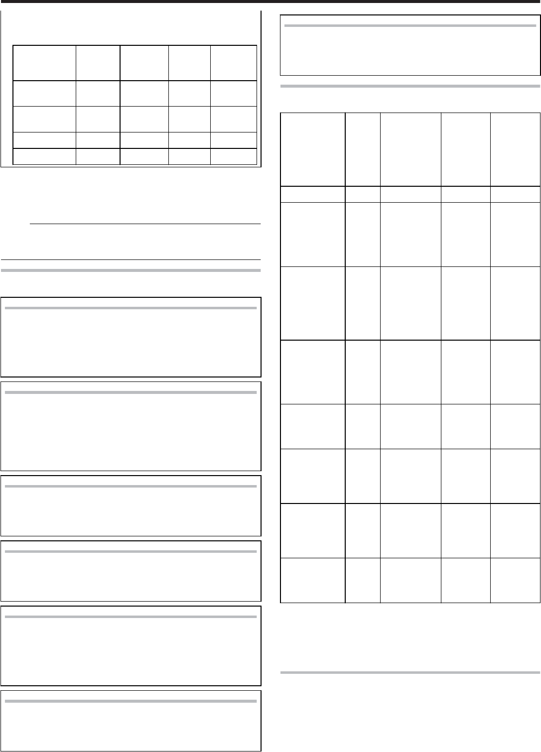
[Printer settings]Dialog
●Settings related to the printer.
Tick the setting item to enable, followed by specifying a value. Doing so
prints the data using the set values.
When this is disabled, data is printed using the preset values of the
printer unit.
Setup
78
Resin K ink print level
●Print density of the Resin K ink.
Use the “+” values to increase, and “-” values to decrease the density.
UV ink print level
●Print density of the UV ink. (Optional)
Use the “+” values to increase, and “-” values to decrease the density.
Special ink 2 print level
●Print density of the Special ink 2. (Optional)
Use the “+” values to increase, and “-” values to decrease the density.
Resin K ink print mode
●Print quality of the Resin K ink.
Selecting “Fine” enhances the printing quality, but slows down the
printing speed.
MG Print
(MG JIS)
●For specifying the way to peel the retransfer film of cards that come
with a JIS magnetic stripe when the JIS MG unit is mounted.
Retransfer
●Settings related to retransfer. Click on the corresponding square to
change the value.
●Setting a value toward the top right end increases the transfer force,
however heat deformation of the card will also be greater.
① TEMP
●Temperature of the retransfer roller.
② SPEED
●Retransfer speed.
Bend Remedy
●Settings related to bend remedy.
Click on the corresponding square to change the value.
●Setting a value toward the top right end increases the bend remedy
force, however impact of heat on the card will also be greater.
●To disable bend remedy, select the "Disable remedy" button.
① TEMP
●Temperature of the bend remedy roller.
② SPEED
●Bend remedy speed.
Note:
●The optimal retransfer and bend remedy settings vary according to the
card type as well as environment in which the printer is used. As such,
set the values after trying out under the environment where it is to be
used.
●If the retransfer or bend remedy settings are different from the preset
temperature of the printer, it may take a while before printing starts.
●There is only one standard retransfer temperature. Altering the retrans-
fer temperature on one side changes the temperature on the other side
as well.
●Bend remedy is effective when printing on only one side. Setting bend
remedy to a high temperature during double-sided printing may cause
the card to deform significantly.
As such, select the “Disable remedy” button during double-sided print-
ing.
●When bend remedy is disabled using the “Disable remedy” button, the
speed is automatically set to the maximum value (+2).
●If the bend remedy force becomes strong, the surface of remedy side
will become lusterless.
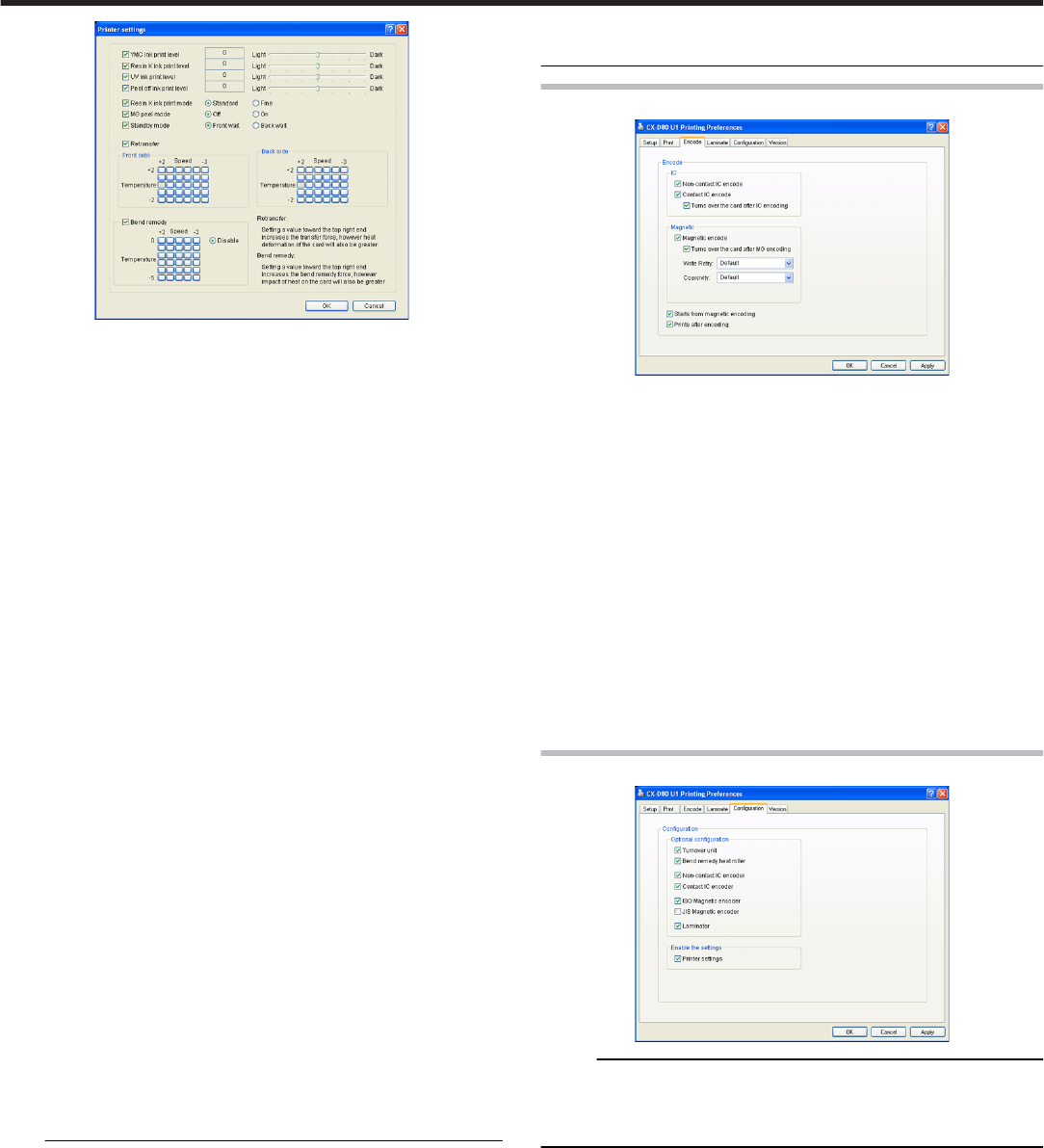
[Encode]Tab Sheet
IC
① Non-contact IC encode
●Allows writing of data to the non-contact IC.
② Contact IC encode
●Allows writing of data to the contact IC.
③ Turns over the card after IC encoding
●Turns over the card after writing data to the non-contact/contact IC.
magnetic
① Magnetic encode
●Allows writing of data to the magnetic stripe.
② Turns over the card after IC encoding
●Turns over the card after writing data to the magnetic stripe.
③ ISO Coercivity
●Coercivity with respect to the ISO magnetic stripe card.
Selecting “Default” writes data using the preset coercivity value of
the printer.
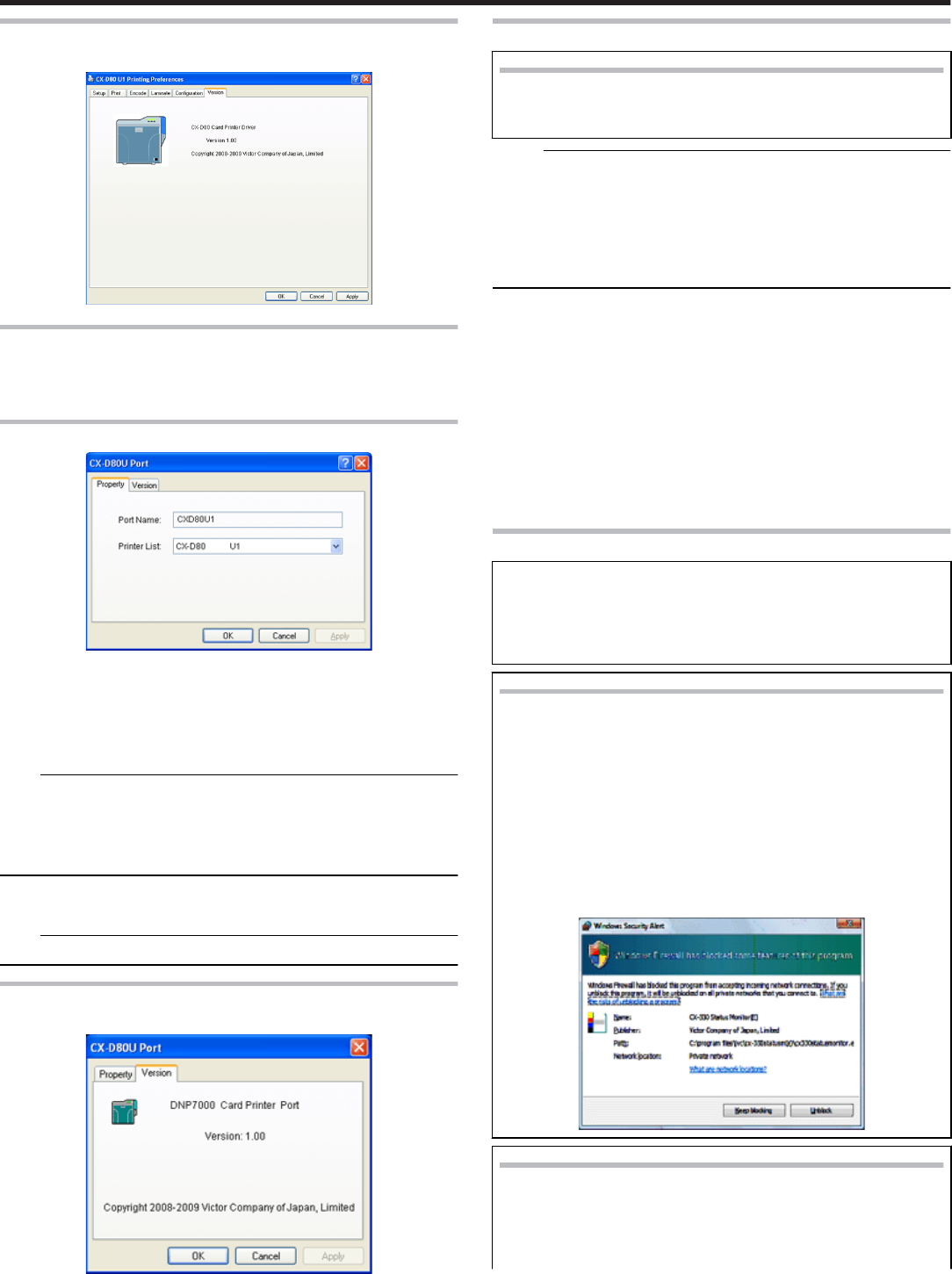
[Configuration]Tab Sheet
Memo:
●When the status monitor runs by an user within the administrator au-
thority (Administrators group), enables the printer settings.
Only run on display when the status monitor runs by an user without
administrator authority.
Configuration of options
●For setting the availability of options.
① Retransfer unit
② Warpage correction heating roller
③ Non-contact IC encoder
④ Contact IC encoder
⑤ ISO magnetic encoder
⑥ JIS magnetic encoder
Allows settings can be changed
●Allows or prohibit the setting [Print] tab sheet.
① Printer Setting
●Allows the setting [Print] tab sheet when select a checkbox.
●Allows the setting [Print] tab sheet when not select a checkbox.
Setup
79
[Version]Tab Sheet
●Version and copyright information.
Port Monitor Settings
"[Property]Tab Sheet" ' page 80
"[Version]Tab Sheet" ' page 80
[Property]Tab Sheet
Port Name
●Name of the port. You can enter a name up to 24 characters.
Printer List
●List of connected printers. The selected printer is used for printing the
card.
Note:
The setting is incorrect if the following message appears.
●No Device:
Printer is not found.
●No selection:
Last used printer is not found. A different printer is currently connected.
[Find…]
●Searches for printers and displays them in the [Printer List].
Note:
●This feature is used exclusively for network port monitor.
[Version]Tab Sheet
●Version and copyright information.
Status Monitor Settings
What is status monitor?
●
●
The status monitor is software for displaying the printer status
as well as specifying various printer settings.
Memo:
●Use the status monitor only when the power of the printer is turned on.
●The printer driver needs to be installed on the host computer. You can
install the printer driver using the CD-ROM supplied with the printer.
●When the status monitor runs by an user within the administrator au-
thority (Administrators group), enables the printer settings.
Only run on display when the status monitor runs by an user without
administrator authority.
●"Executing the Status Monitor" ' page 80
●"Screen Configuration" ' page 81
●"[Printer Status]Tab Sheet" ' page 81
●"[Printer Setting]Tab Sheet" ' page 82
●"[Retransfer]Tab Sheet" ' page 83
●"[Bend Remedy]Tab Sheet" ' page 84
●"[Media Setting]Tab Sheet" ' page 84
●"[Property]Tab Sheet" ' page 84]
●"[Printer Select]Tab Sheet" ' page 85
●"[Security Lock]Tab Sheet" ' page 86
●"[Others]Tab Sheet" ' page 86
Executing the Status Monitor
The status monitor runs on the following method.
●Runs by the shortcut of desktop. (This setting is at the installa-
tion.)
●Runs by the start menu. (This setting is at the installation.)
●Runs directly by installed folder of the program.
Windows Vista
●Choose the “Run as administrator”, and the status monitor runs
by an user within administrator authority. Open or double-click
the icon of the status monitor, it runs by an user without admin-
istrator authority.
●Even if an user logged on with the administrator account, the
status monitor may be run by an user without administrator au-
thority.
●The following Windows dialog may appear when you first start
up the status monitor using Windows Vista. This dialog will not
appear again if you set to “Unblock”. The status monitor incor-
rectly runs if you set to “Keep Blocking”.
Windows Vista/Windows XP
●The following Windows dialog may appear when you first start
up the status monitor using Windows XP. This dialog will not
appear again if you set to “Unblock”. The status monitor incor-
rectly runs if you set to “Keep Blocking”.
Setup
80
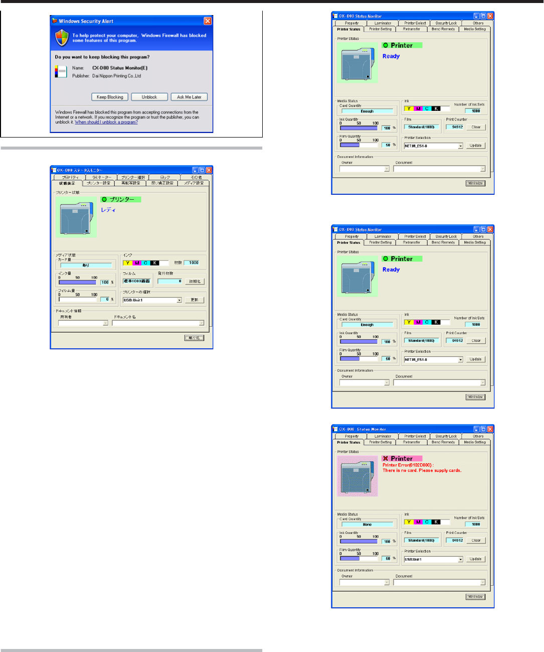
Screen Configuration
Close button
●Closes the status monitor.
Screen selection tabs
●Use these to switch to the following screens.
① Printer Status
●Displays the printer’s status.
② Printer Setting
●Displays and enables specification of the printer’s print settings.
③ Retransfer
●Displays and enables setting of the conditions during retransfer of
the card.
④ Bend Remedy
●Displays and enables setting of the conditions during bend remedy of
the card.
⑤ Media Setting
●Displays the ink ribbon’s status and enables setting of the card or re-
transfer film.
⑥ Property
●For verifying the device configuration as well as printer’s firmware
version.
⑦ Others
●For performing test prints and specifying other settings.
[Minimize button]
●Minimizes the status monitor to an icon. The icon is displayed in the
task bar.
[Printer Status]Tab Sheet
●Displays the printer’s status. Content of the screen is automatically up-
dated at regular intervals.
Printer Status
●Ready status. The printer is ready to start printing.
●Error has occurred.
●Printer is busy.
Setup
81
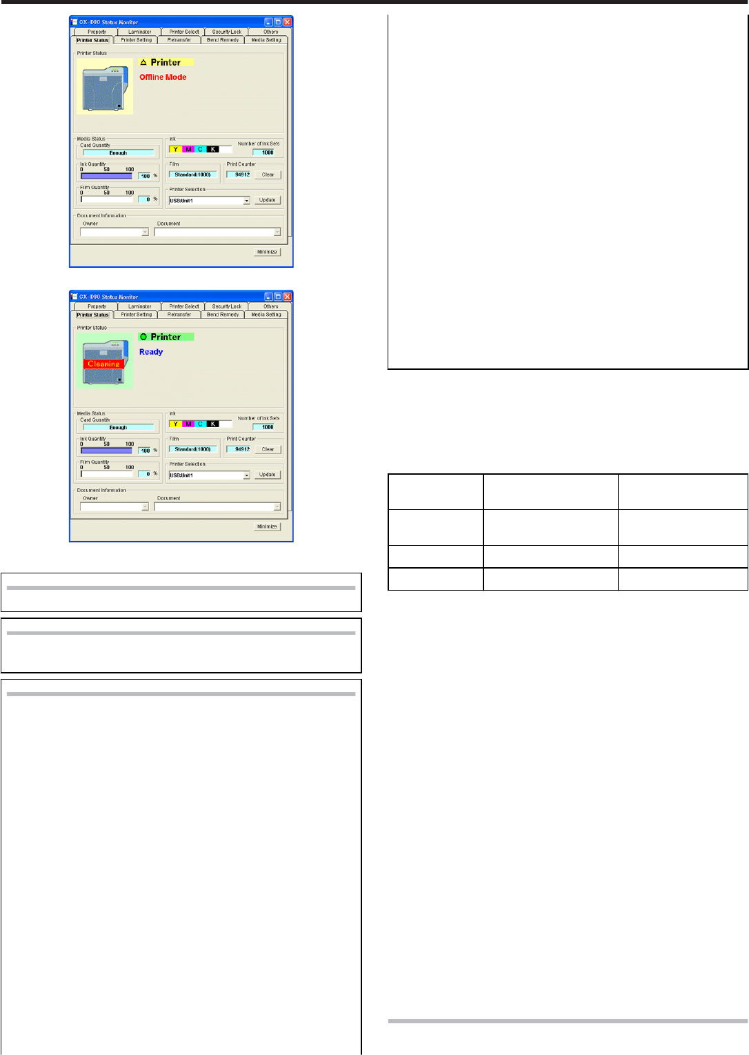
●When Roller Cleaning is Required
Printer icon
Under Normal Circumstances
When Roller Cleaning is Required
●
●
Clean the card feed roller and heating roller.
Printer status message
●No printer is found:
The power of the printer is not turned on, or the host computer
is not properly connected to the printer.
●Ready:
The printer is in the ready mode. The printer is ready to start
printing cards.
●Initializing:
Printer initializing. The printer switches to the Ready mode after
initialization is complete.
●Offline Mode:
The printer is in the setting mode, or roller cleaning is in pro-
gress. When this is complete, the printer switches to the Ready
mode.
●Preheating:
Preheating of the heat roller is in progress. The printer switches
to the Ready mode upon reaching an appropriate temperature.
●Card Loading:
The printer is issuing cards. The printer’s operating status when
issuing cards is displayed. After card issuance is complete, the
printer returns to the Ready mode.
●Card Transporting:
The printer is issuing cards. The printer’s operating status when
issuing cards is displayed. After card issuance is complete, the
printer returns to the Ready mode.
●MG Encoding:
The printer is issuing cards. The printer’s operating status when
issuing cards is displayed. After card issuance is complete, the
printer returns to the Ready mode.
●Retransfer:
The printer is issuing cards. The printer’s operating status when
issuing cards is displayed. After card issuance is complete, the
printer returns to the Ready mode.
●Contact IC Encoding:
The printer is issuing cards. The printer’s operating status when
issuing cards is displayed. After card issuance is complete, the
printer returns to the Ready mode.
●No-Contact IC Encoding:
The printer is issuing cards. The printer’s operating status when
issuing cards is displayed. After card issuance is complete, the
printer returns to the Ready mode.
●Printing:
The printer is issuing cards. The printer’s operating status when
issuing cards is displayed. After card issuance is complete, the
printer returns to the Ready mode.
●Power Saving:
The printer is in the Power Saving mode, which helps to reduce
power consumption. To exit the Power Saving mode, press the
[Reset] button, followed by the B button to initialize the
printer.
Media Status
●Displays the media’s remaining space available.
Card Quantity
●Displays the remaining card quantity as three different levels as shown
below. The display may vary according to the thickness as well as
bend of the card.
Card Quantity
Display
Card Thickness of 0.76
mm
Card Thickness of
0.01in
Enough Approx. 25 cards or
more
Approx. 70 cards or
more
Less Less than 25 cards Less than 70 cards
None No card No card
Ink Quantity
●Displays the remaining ink ribbon quantity in 50 different levels in per-
centage.
Film Quantity
●Displays the remaining card quantity as three different levels as shown
below.
●The remaining quantity shown is an estimated value. Differences may
occur according to the usage as well as media type.
Ink
●Displays the information on the mounted ink ribbon. The print counter
appears blank if the ink ribbon is not correctly recognized.
You may not be able to control the ink ribbon properly in this case.
Film
●Displays the type of retransfer film mounted.
Print Counter
●Displays the number of cards that have been issued. Press the “Clear”
button to reset the print counter to 0.
Printer Selection
●You can switch to the relevant printer when multiple printers are con-
nected to a single host computer.
●Pressing the “Update” button searches for a connected printer and up-
dates the printer in the list box.
Document Info
●Displays the owner and document names when printing is enabled
through a network connection.
[Printer Setting]Tab Sheet
●For specifying settings of the printer.
Setup
82
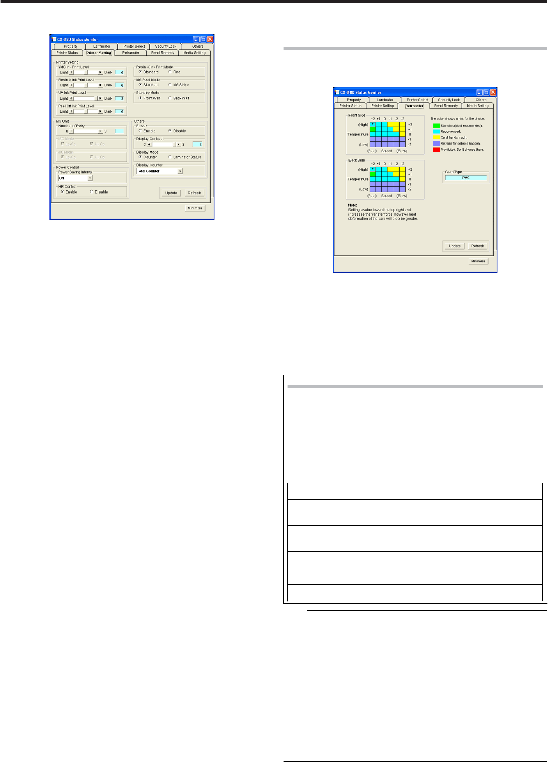
●Make sure that you take down the set values before making any
changes.
Print Settings
① Resin K Ink Print Level
●For setting the print density level of the Resin K ink.
② UV Ink Print Level
●For setting the print density level of the UV ink. (Optional)
③ Special ink 2 print level
●For setting the print density level of the Special Ink 2. (Optional)
④ Resin K Ink Print Mode
●For setting the print quality using the Resin K ink. Selecting “Fine”
enhances the printing quality, but slows down the printing speed.
⑤ MG Print (JIS)
●For specifying the way to peel the retransfer film of cards that come
with a JIS magnetic stripe when the JIS MG unit is mounted. The de-
fault setting is “Disable”.
⑥ Standby Mode
●For specifying the card standby position while waiting for the lamina-
tor to switch to the Ready mode during double-sided printing when
the laminator is connected. The default setting is “Front Wait”.
Magnetic encoder
① Number of Retry
●For specifying the maximum number of retries when writing/reading
of the magnetic stripe fails. The default value is 1.
② ISO Mode
●For specifying the coercivity with respect to the ISO magnetic stripe.
The default setting is “Hi-Co”.
Encoder Unit
Others
① Buzzer
●For [enabling]/[disabling] the alert sound when error occurs or when
the card quantity is running low, as well as the sound upon pressing
the B key in the user mode.
The buzzer does not sound if you [disable] this feature. The default
setting is “Enable”.
② Power Saving Interval
●Enables switching to the Power Save mode to reduce power con-
sumption when printing or operation is not performed over a speci-
fied time interval.
Select whether to disable the Power Save mode or the time interval
before switching to the Power Save mode.
Selecting “Disable” deactivates the Power Save mode. The default
setting is “Disable”.
③ HR Control
●Switches to the standby mode by lowering the temperature of the re-
transfer heat roller when printing is not performed for 30 minutes or
longer. The default setting is “Enable”.
[Update]
●Enables the printer settings specified using the slide bars, radio buttons
and list box.
[Refresh]
●Displays the printer settings on the screen.
[Minimize]
[Retransfer]Tab Sheet
●The “Retransfer” screen enables you to set the retransfer conditions on
the card.
Card Type
●The appropriate value varies according to the type of card used.
[Update]
●Applies the selected value to the printer.
[Refresh]
●Displays the printer settings on the screen.
[Minimize]
Setting Procedures
●
●
The vertical axis shown in the setting area indicates the retrans-
fer temperature, and the horizontal axis represents the retrans-
fer speed. Click on the corresponding square to change the val-
ue.
The selected value is indicated using “*”.
Setting a value toward the top right end increases the transfer
force, however heat deformation of the card will also be greater.
The colors below serve as a rough indicator for selection.
Color Description
Green Standard value. Optimal value for the selected
card. Select this under normal circumstances.
Light Blue Appropriate range. Recommended range when
selecting a value other than the standard value.
Yellow Card bends increases.
Blue Retransfer defect may occur.
Red Do not choose these values.
Note:
●The setting areas serve only as a rough indicator. The optimal value
varies according to the card type as well as the environment in which
the printer is used. As such, set the values after trying out under the
environment where it is to be used.
●It may take a while for printing to start when the retransfer temperature
is changed.
●There is only one standard retransfer temperature. Altering the retrans-
fer temperature on one side changes the temperature on the other side
as well.
●The range of optimal values varies according to the “Card Type”. You
can change the card type in the “Media Setting” screen.
●If the card type varies across printers, set the card type to use accord-
ingly. The color of the setting area varies according to the card type in
use.
Setup
83
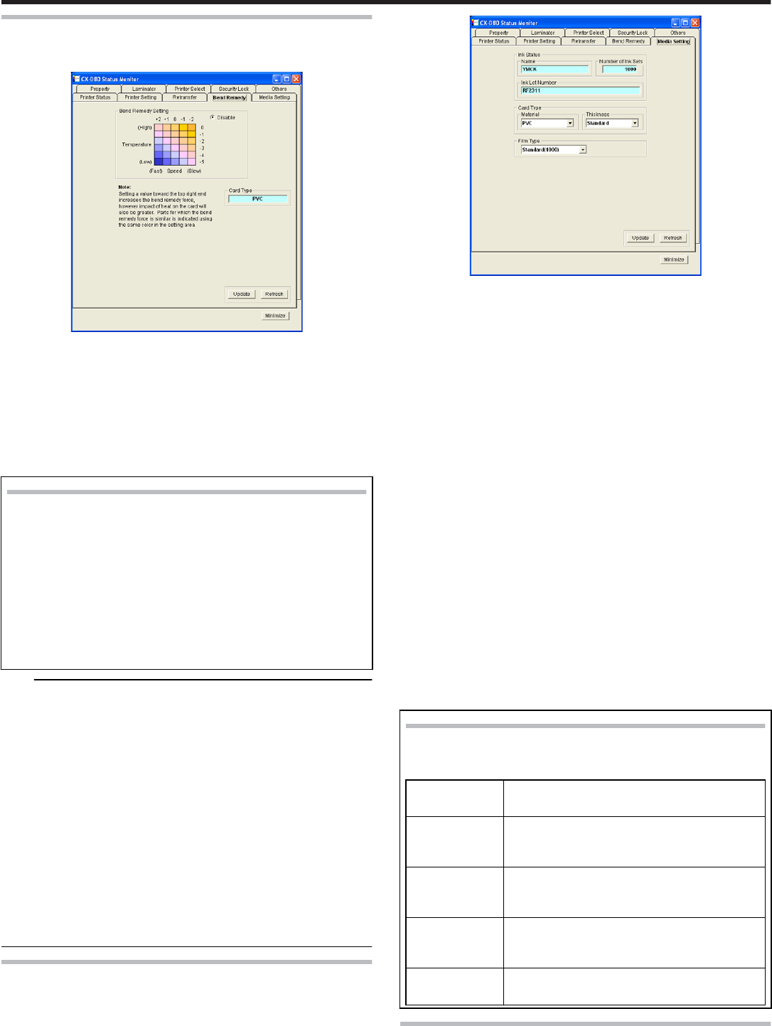
[Bend Remedy]Tab Sheet
●The “Bend Remedy” screen enables you to set the conditions for the
card’s bend remedy.
Card Type
●The appropriate value varies according to the type of card used.
[Update]
●Applies the selected value to the printer.
[Refresh]
●Displays the printer settings on the screen.
[Minimize]
Setting Procedures
●
●
The vertical axis in the setting area indicates the bend remedy
temperature, and the horizontal axis represents the bend reme-
dy speed. Click on the corresponding square to change the val-
ue.
The selected value is indicated using “*”.
Setting a value toward the top right end increases the bend rem-
edy force, however impact of heat on the card will also be great-
er. Parts for which the bend remedy force is similar is indicated
using the same color in the setting area.
To disable bend remedy, select the “Disable” radio button. de-
fault setting is “Disable”.
Note:
●The setting areas serve only as a rough indicator. The optimal value
varies according to the card type as well as the environment in which
the printer is used. As such, set the values after trying out under the
environment where it is to be used.
●Bend remedy is effective when printing on only one side. Performing
double-sided printing with a high bend remedy temperature may cause
the card to deform significantly.
As such, select the “Disable remedy” button during double-sided print-
ing.
●When the “Disable” radio button is turned on, the printer switches to
and remains in the preheating mode (for approximately 10 minutes) un-
til the bendy remedy roller’s temperature has gone down.
This is not a malfunction. Wait for the printer to switch to the Ready
mode.
●When bend remedy is disabled using the “Disable remedy” button, the
speed is automatically set to the maximum value (+2).
●If the bend remedy force becomes strong, the surface of remedy side
will become lusterless.
[Media Setting]Tab Sheet
●For specifying settings of the Printing media.
Ink Status
① Name
●Displays the name of the mounted ink ribbon. A message indicating
the cause appears when the ink ribbon cannot be recognized.
② Number of Ink Sets
●Displays the specification of the number of screens which is mounted
ink ribbon. This is not an indication of the current ink level.
③ Ink Lot Number
Card Type
① Material
●Select one of the card materials from “PET-G”, “PVC”, and “PET
(0.25 mm)”. An optimal value for the retransfer speed and tempera-
ture settings is displayed according to the selected card.
② Thickness
●Select either “Standard” or “Thin” for the card thickness. If the card
thickness is 0.76 mm, select “Standard”. If the card thickness is 0.25
mm, select “Thin”.
●To use cards of different thickness, refer to “Switching the card thick-
ness” .
"Adjusting Card Thickness" (' page 55)
Film Type
●Displays the specifications of the number of screens which is mounted
retransfer film. This is not an indication of the current film level.
① [Update]
●Applies the selected value to the printer.
② [Refresh]
●Displays the printer settings on the screen.
When the ink ribbon cannot be recognized
●When the ink ribbon cannot be recognized, the cause for this
problem is indicated in the “Name” field under “Ink Status”.
Message Cause and Action to Take During Ink Recog-
nition Error
(252:Invalid
TAG Data)
The TAG record data adhered to the ink rib-
bon is incorrect. Replace the ink ribbon and
try again.
(253:Defective
TAG)
Unable to establish communication with the
TAG adhered to the ink ribbon. Replace the
ink ribbon and try again.
(254:No TAG) Unable to read the TAG adhered to the ink
ribbon. Check to ensure that the ink ribbon
is correctly set.
(255:Defective
R/W)
Printer TAG reader error. The printer needs
to be repaired.
[Property]Tab Sheet
●For verifying the device configuration as well as printer’s firmware ver-
sion.
Setup
84
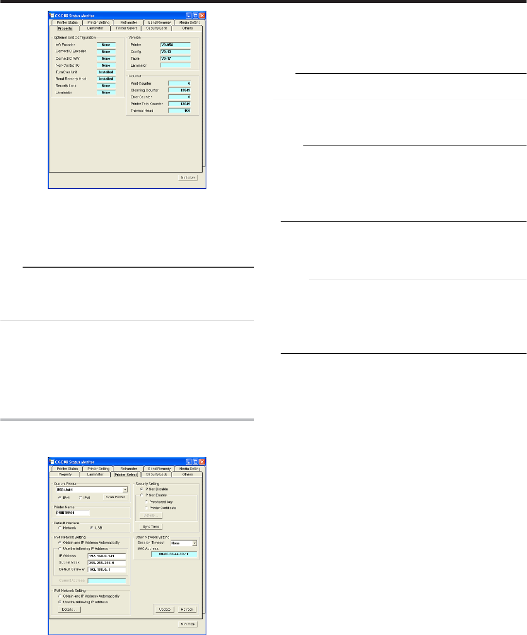
Version
●Displays the firmware version of the printer as well as peripheral devi-
ces. When optional devices, such as the MG unit, and laminator, are
not connected, this is indicated as “????”.
Optional Unit Configuration
●Displays the configuration of optional devices.
Note:
●When a value other than ”None” is shown in the contact IC encoder or
non-contact IC encoder field, this means the configuration allows
mounting of an IC encoder, and does not indicate that an IC encoder is
mounted. Consult our authorized dealers on how to install the IC en-
coder.
Others
●: Displays the printer’s status.
① Printer Print Counter
●Displays the accumulated number of cards issued by the printer.
② Thermal Head Counter
●Displays the number of print ink panels for the thermal head.
For example, when printing on a single side using all YMCK inks, 4
are added to each card.
[Printer Select]Tab Sheet
●The “Property” screen enables you to verify the device configuration as
well as the printer’s firmware version.
Printer Selection
●You can switch to the relevant printer when multiple printers are con-
nected to a single host computer.
① [Scan Printer]
●Pressing the “Scan Printer” button searches for a connected printer
and updates the printer in the list box.
② Pull-down menu
●When a printer is selected from the list box, the status of the selected
printer is automatically displayed.
Printer Name
●For setting the name of the selected printer.
Default Interface
●For setting the interface during startup. When the printer is connected
via the network (Ethernet), the set value is shown but setting is disa-
bled.
Note:
●Regardless of the default interface setting, priority is given to USB if the
USB cable is connected.
① Network Settings
●For specifying items related to the network (Ethernet). When the
printer is connected via the network, the set values are shown but
setting is disabled.
Note:
●Determine the network setting items according to the instructions of
the network administrator for the location where the printer unit is in-
stalled.
●Other network devices may be affected if the network setting is incor-
rect.
●When only USB connection is used, there is no need to specify the
network setting.
② Obtain and IP Address Automatocally
●When “Obtain and IP Address Automatically” is selected, the IP ad-
dress, subnet mask, and default gateway values are automatically
acquired from the DHCP server. If the DHCP server is not found, set-
tings in the “Use the following IP Address” will apply.
Memo:
●The IP address, subnet mask, and default gateway values that are
automatically acquired from the DHCP server are not shown.
●The IP address, subnet mask, and default gateway values may
change regularly according to the DHCP server settings.
To use a static IP address such as for the printer driver’s application
software, it is recommended that you select “Use the following IP Ad-
dress”.
③ Use the following IP Address
●When “Use the following IP Address” is selected, specify the “IP Ad-
dress”, “Subnet Mask”, and “Default Gateway” fields accordingly.
Session Timeout
●Use “Session Timeout” to specify the timer interval before disconnect-
ing when communication is not established after print connection. The
default setting is “None”.
① MAC Address
●The printer’s MAC address is shown in the “MAC Address” field.
Security setting
●Security Setting: For specifying items related to IPSec of the network
(Ethernet). When the printer is connected via the network, the set val-
ues are shown but setting is disabled.
●Determine the “Security Setting” items according to the instructions of
the network administrator for the location where the printer unit is in-
stalled.
●Encrypted communication cannot be established if the “Security Set-
ting” is incorrect.
●When only USB connection is used, there is no need to specify the
“Security Settings”. Encrypted communication is not possible with USB
connection.
●It is not possible to apply the “Security Setting” to the printer without
connecting via USB.
●Refer to the “Installation Manual” for procedures to create the down-
load file to be used for the “Security Setting”. Manage the download file
according to the instructions of the network administrator.
① IP Sec Disable
●When “IP Sec Disable” is selected, only communication that does not
make use of IP Sec is enabled. The default setting is “IP Sec Disa-
ble”.
② IP Sec Enable
●When “IP Sec Enable” is selected, communication that makes use of
IP Sec is enabled. Upon completing the setting using the “Details”
button, the “Preshared Key” or “Printer Certificate” selection is ena-
bled.
Setup
85
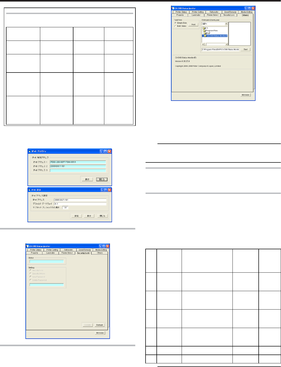
Refer to the table below on whether encrypted communi-
cation using IP Sec is allowed.
Printer Set-
ting
PC’s IP Sec
Policy
PC’s IP Sec
Policy
PC’s IP
Sec Policy
Printer Set-
ting
Security Re-
quired
Request for
Security
Not Protec-
ted
“IP Sec Disa-
ble”
Communica-
tion Disabled
Normal
Communi-
cation
Normal
Communi-
cation
“IP Sec Ena-
ble” (When
authentica-
tion fails)
Communica-
tion Disabled
Normal
Communi-
cation
Normal
Communi-
cation
“IP Sec Ena-
ble” (When
authentica-
tion is suc-
cessful)
Encrypted
Communica-
tion
Encrypted
Communi-
cation
Normal
Communi-
cation
③ “Details”
●Pressing the “Details” button displays the “IP Sec Setting” screen,
and enables you to send the download file required for IP Sec au-
thentication to the printer.
[Security Lock]Tab Sheet
●Security Settings.
[Others]Tab Sheet
●Test print uses the printer’s self-diagnosis function without making use
of the printer driver.
You can use it to verify whether the printer is functioning correctly.
●For printers connected via the network, the items on this screen are not
displayed.
Test print
●Doing so executes printing on a card using the built-in test pattern of
the printer.
Firmware Download
●Updates the printer’s firmware. Special operations are required to up-
date the printer’s firmware.
Note:
●Request the servicing personnel or our authorized dealer to update the
printer’s firmware. The printer may not start up if update of the firmware
fails.
Inline Encoding
●"In-Line Encoding Format" ' page 86
●"Character Code Table" ' page 87
In-Line Encoding Format
●In-line encoding is possible when all the settings in the [Encode] tab
are enabled.
Encoding data can be sent to the printer through the printer driver us-
ing the special character strings (prefixes) described below.
This function is called as “in-line encoding”.
●Adding a prefix (tilde (~),?, or numeric characters) at the beginning of a
text string enables the string to be recognized as encoding data. Char-
acter strings including prefixes are not printed on the card when they
are recognized as encoding data.
No. Prefix
character
string
Text string following
prefix (1)
Usable
character
code table
(2)
Max.
string
length
(3)
1 ~ ?0 String becomes JIS2
magnetic encoding da-
ta.④
7 units
code
69.00
2 ~ ?1 String becomes ISO
track 1 magnetic encod-
ing data.
6 units
code
76.00
3 ~ ?2 String becomes ISO
track 2 magnetic encod-
ing data.
4 units
code
37.00
4 ~ ?3 String becomes ISO
track 3 magnetic encod-
ing data.
4 units
code
104.00
5 ~ ?4 Reserved. - -
6 ~ ?5 Reserved. - -
Note:
① Make sure that the string is not broken and uses the same font.
② Encoding cannot be performed correctly if characters that are not
consistent with the usable code table are used.
③ The maximum string length is the number of characters including
control codes and excluding prefixes.
Setup
86
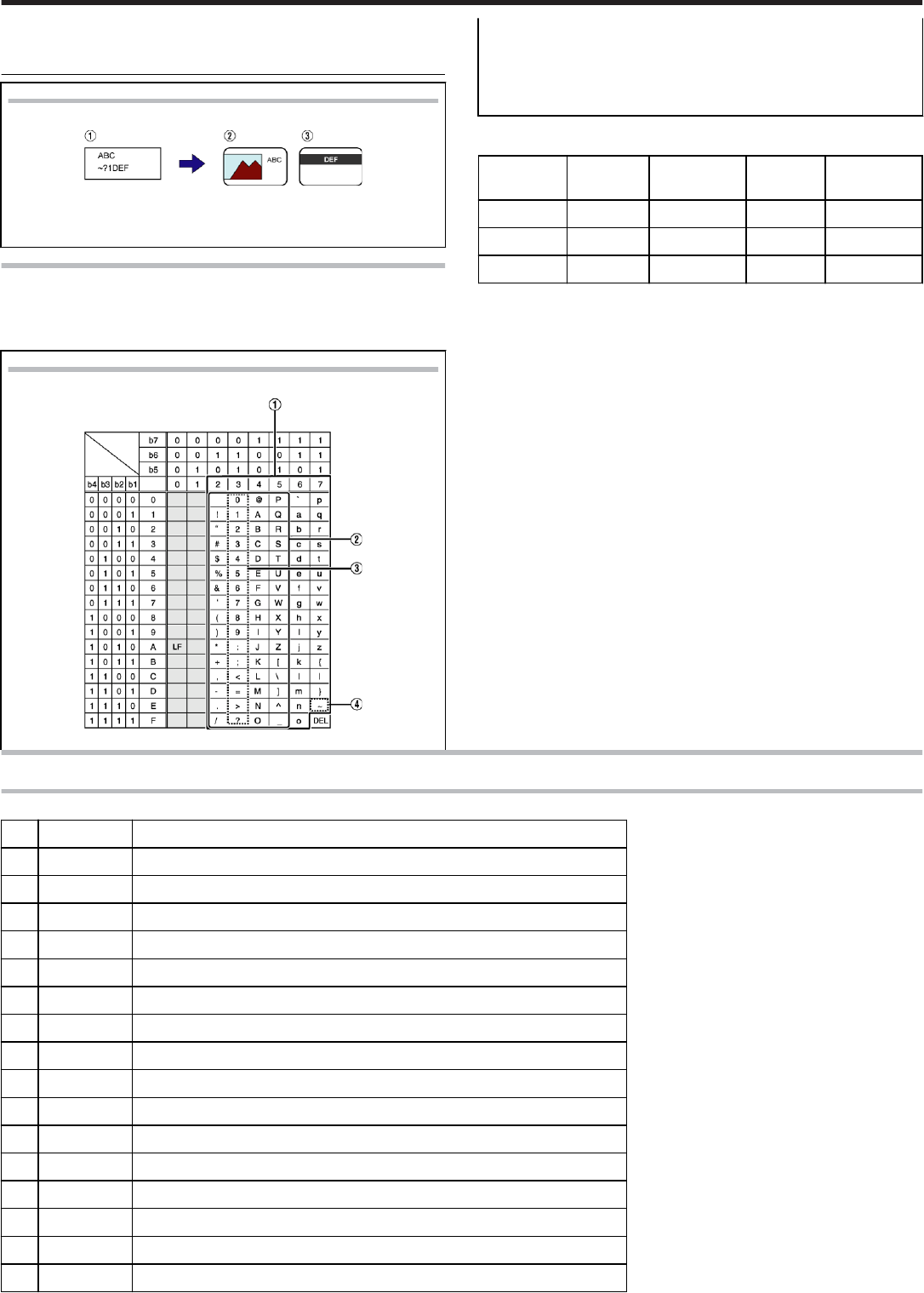
④
⑤
⑥
Example
.
①
①
Textbox character strings of application software
② Character string to be printed on card
③ Encoding data to be sent to ISO track 1
Character Code Table
●Below is the list of usable ASCII codes. Configure the character string
to encode using the usable half-size characters for each of the level co-
des.
ASCII character code table
.
① The range of 7 units code for a text string.
② The range of 6 units code.
③ The range of 4 units code.
④ Tilde character
(Hex-decimal: 7E)
●The start sentinel and end sentinel listed below cannot be used in the
encoding data.
Units code Start sen-
tinel
(Hexadeci-
mal value)
End sen-
tinel
(Hexadeci-
mal value)
4 units code ; (3B) ? (3F)
6 units code % (-25) ? (3F)
7 units code DEL (7F) DEL (7F)
List of Error Codes
Printer
No. Error code Description
1 0x0102D000 Replenish cards into the card tray.
2 0x0102D100 Printer door is open.
3 0x0102D300 Printer is busy.
3 0x0102D400 Printer is busy.
3 0x0102D500 Printer is busy.
4 0x0102D600 No ink ribbon cassette or retransfer film cassette.
5 0x0102D700 Cleaning unit is not mounted.
6 0x0102DA00 Preheating.
7 0x0102DB00 Printer initializing.
8 0x0102DC00 Offline test in progress or cleaning in progress.
9 0x0102DD00 The operation panel is currently being used, or the “transport mode” is selected.
10 0x0102FD00 Power-saving mode.
11 0x0102FE00 Password authentication is not complete.
12 0x0102**** Printer is not ready.
13 0x01039000 Failure in loading a card.
14 0x01039100 Card jam.
Setup
87
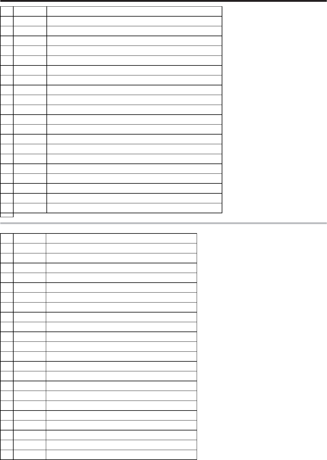
14 0x01039200 Card jam.
14 0x01039300 Card jam.
14 0x01039400 Card jam.
15 0x01039500 No card in the right paper feeder.
16 0x0103A000 Retransfer film has been cut off.
17 0x0103A100 Retransfer film is not detected.
18 0x0103AD00 Writing of magnetic encoding data failed.
18 0x0103AE00 Writing of magnetic encoding data failed.
19 0x0103B000 Ink ribbon has been cut off.
20 0x0103B100 Ink ribbon is not detected.
21 0x0103BB00 Card jam in the external IC unit.
22 0x0103**** Media error is detected.
23 0x0104**** Hardware error is detected.
24 0x01052700 Ink ribbon specification is incorrect.
25 0x01052B00 Incorrect magnetic encoding data.
26 0x01052C00 IC encoder is not mounted.
27 0x01052D00 Magnetic encoder is not mounted.
28 0x0105**** Command error is detected.
28 0x010B**** Command error is detected.
29 0x0142A200 Retransfer film has run out.
30 0x0142B200 Ink ribbon has run out.
Printer driver
No. Error code Description
1 0x02****** Printer is not found.
2 0x03002741 Printer is not found.
2 0x0300274C Printer is not found.
3 0x03****** Unexpected problems have occurred.
4 0x04000003 Printer has been disconnected.
5 0x04000004 Incorrect operation.
6 0x04000005 Operation did not complete in time.
7 0x04000006 Abnormal data has been received.
8 0x04100001 Printer is busy and unable to accept request.
9 0x04100021 Abnormal data has been received.
10 0x04****** Unexpected problems have occurred.
11 0x09****** Command error is detected.
12 0x10000103 Writing of magnetic encoding data failed.
13 0x10000201 Contact IC encoding program is not found.
14 0x10000202 Unable to establish communication with the contact IC encoder.
15 0x10000203 Writing of contact IC encoding data failed.
16 0x10000301 Non-contact IC encoding program is not found.
17 0x10000302 Unable to establish communication with the non-contact IC encoder.
18 0x10000303 Writing of non-contact IC encoding data failed.
19 0x10000401 User program is not found.
20 0x10000403 An error is returned for the user function.
21 0x10001001 Ink ribbon cannot be recognized.
Setup
88
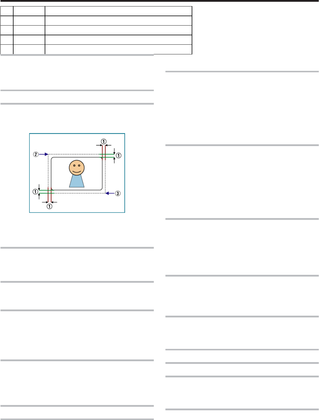
22 0x10001002 Ink ribbon specification is incorrect.
23 0x10001003 IC encoder is not mounted.
24 0x10001004 Magnetic encoder is not mounted.
25 0x10002000 Printer is not found.
26 0x1000200* Printer is not ready.
Frequently Asked Questions
●"Printing Settings" ' page 89
●"UV ink" ' page 89
●"Others" ' page 89
About print settings
The edge of picture is not printed
●Check the margins of printing in the application software.
●About 1 mm portion is not printed from the end of a picture to a card.
Refer to the following figures.
About 1 mm
(X=0, Y=0)
(About X=87.5 mm, About Y=56.0 mm)
The card is discharged without being printed
●The [Print] check box of the [Print] tab is not ticked. Tick the [Print]
check box.
"[Print]Tab Sheet" (' page 74)
How can I print black color using the Resin K ink ?
●Choose the [Mode] item of [Printing] tab except “1.YMC”.
"[Print]Tab Sheet" (' page 74)
How can I print a card using the “Security erase” ?
●Choose either “2. K” or “3. YMCK” in the [Mode] item of [Printing] tab,
and tick the [Security erase] check box.
Then, the “Security erase” function to resin K ink will become effective.
The “Security erase” function is available only when using the YMCK
ink.
Please consult our authorized dealers for details.
I want to memorize contents of “Printing Preferences”.
●A When you click the [Save ...] button of [Setup] tab, contents of “Print-
ing Preferences” can be saved at a file. When you click the [Load...]
button of [Setup] tab, contents of “Printing Preferences” can load from
the saved file.
"[Setup]Tab Sheet" (' page 74)
About UV ink
How can I print a card using the UV ink ?
●A Choose either "5.K+UV", "6.YMCK+UV" or "4. YMC+UV"of the
[Mode] item of [Printing] tab, and set the UV function using the [UV ink]
button. If the UV ink is not installed into the printer, the error occurs at
the printing.
"[Print]Tab Sheet" (' page 74)
"[UV ink]Dialog" (' page 76)
When I print a card using the UV ink, the picture of the upper
right position is not printed.
●In the case of UV print, the printer always prints the network (Ethernet)
MAC address. When you set the “Number of panels using the retrans-
fer film” to “1 panel” in this case, the printer does not print the picture
inside of MAC address area.
Please arrange the picture so that printing of the YMCK ink does not
overlap in MAC address area.
When you set the “Number of panels using the retransfer film” to “2
panels”, the printer can print the whole picture using the YMCK ink.
"About the MAC address position" (' page 77)
When I print a card using the UV ink, a part of picture is not
printed.
●When you set the “Number of panels using the retransfer film” to “1
panel”, the part of overlaps between the YMC ink and UV ink is not
printed.
Please arrange the picture so that printing of the YMC ink does not
overlap with the UV ink.
When you set the “Number of panels using the retransfer film” to “2
panels”, the printer can print the whole picture using the YMCK ink.
"The number of panels using the retransfer film at the time of printing" (
' page 78)
How can I print the picture with the UV ink without the back-
ground color ?
●Paint over the background of picture by a specific color using graphic
software etc.
Set the specific color by [No printing color] of [UV ink] dialog.
If background color is the same as part of the picture, it will not be prin-
ted. So please select background color carefully.
"No printing color" (' page 76)
Although I chose the picture files in the [UV ink] dialog, the
picture is not printed with the UV ink.
●The picture files do not meet the supporting types.
"File type of Windows Bitmap" (' page 78)
●Other application software may be using the picture files.
When I print a card using the UV ink, a picture of UV ink is
not printed on the Resin K ink.
●When you set the “Number of panels using the retransfer film” to “1
panel”, there is no UV effect on the Resin K ink.
Others
Others
How can I perform magnetic/IC encoding ?
●Exclusive applications are required for methods other than in-line en-
coding.
Please consult our authorized dealers for details.
I cannot print a card using a network-shared printer which
connected via USB.
●When the access authority of the computer is not proper, the printer
may be unable to print, even if installation of the printer driver is com-
pleted by the shared network.
Setup
89

Please make the access authority properly according to the instructions
of the network administrator. Printer Setting
●"Operation Panel" ' page 11
●"Setting using the operation panel" ' page 17
Operation Panel
●"Name and functions of parts" ' page 11
●"Operation buttons" ' page 11
●"Operation Panel Display" ' page 12
●"Operation panel operation display" ' page 12
Setting using the operation panel
●"Initialization" ' page 17
●"Initializing printer when attaching the cassette" ' page 17
●"Firmware update" ' page 18
●"Counter setting" ' page 19
●"Resetting the counter" ' page 20
●"Test print" ' page 20
●"Operation panel contrast settings" ' page 21
●"Buzzer sound setting" ' page 22
●"Unit number setting" ' page 23
●"Transport mode setting" ' page 24
●"Security setting" ' page 25
Setup
90