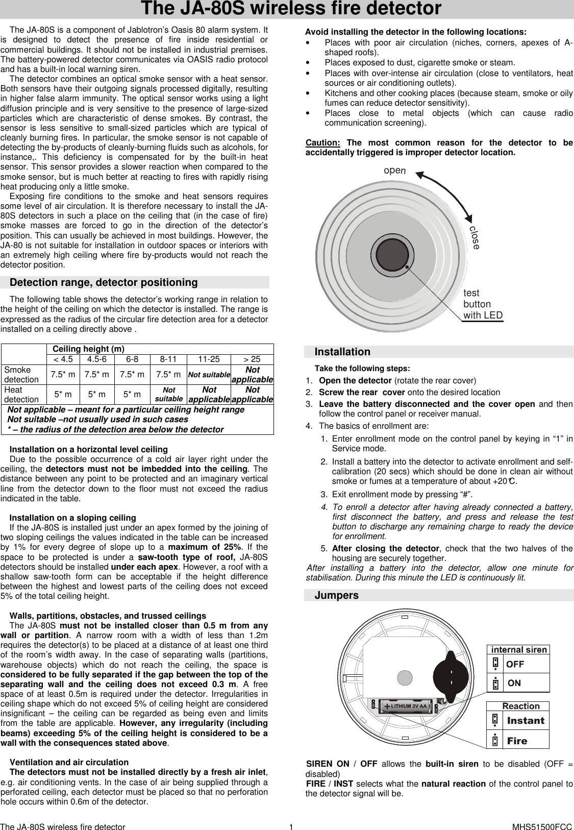
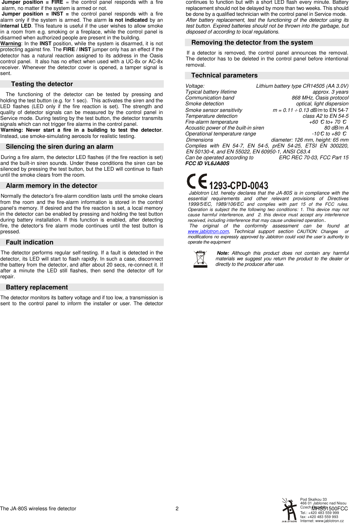
Jablotron JA80S Wireless fire detector_component of alarm system User Manual Exhibit 7 Instruction manual JA80S

Jablotron Ltd Wireless fire detector_component of alarm system Exhibit 7 Instruction manual JA80S

Instructional Manual

The JA-80S wireless fire detector    MHS51500FCC 1  The JA-80S wireless fire detector   The JA-80S is a component of Jablotron’s Oasis 80 alarm system. It is  designed  to  detect  the  presence  of  fire  inside  residential  or commercial buildings. It should not be installed in industrial premises.  The battery-powered detector communicates via OASIS radio protocol and has a built-in local warning siren. The detector combines an optical smoke sensor with a heat sensor. Both sensors have their outgoing signals processed digitally, resulting in higher false alarm immunity. The optical sensor works using a light diffusion principle and is very sensitive to the presence of large-sized particles  which  are  characteristic  of  dense  smokes.  By  contrast,  the sensor  is  less  sensitive  to  small-sized  particles  which  are  typical  of cleanly burning fires. In particular, the smoke sensor is not capable of detecting the by-products of cleanly-burning fluids such as alcohols, for instance,.  This  deficiency  is  compensated  for  by  the  built-in  heat sensor. This sensor provides a slower reaction when compared to the smoke sensor, but is much better at reacting to fires with rapidly rising heat producing only a little smoke. Exposing  fire  conditions  to  the  smoke  and  heat  sensors  requires some level of air circulation. It is therefore necessary to install the JA-80S detectors in such a place on the ceiling that (in the case of fire) smoke  masses  are  forced  to  go  in  the  direction  of  the  detector’s position. This can usually be achieved in most buildings. However, the JA-80 is not suitable for installation in outdoor spaces or interiors with an extremely high ceiling where fire by-products would not reach the detector position. Detection range, detector positioning The following table shows the detector’s working range in relation to the height of the ceiling on which the detector is installed. The range is expressed as the radius of the circular fire detection area for a detector installed on a ceiling directly above .  Ceiling height (m)   < 4.5  4.5-6  6-8  8-11  11-25  > 25 Smoke  detection  7.5* m 7.5* m  7.5* m  7.5* m Not suitable Not applicable Heat detection  5* m  5* m  5* m Not suitable Not applicable Not applicable Not applicable – meant for a particular ceiling height range Not suitable –not usually used in such cases * – the radius of the detection area below the detector  Installation on a horizontal level ceiling  Due  to the  possible  occurrence of  a cold air  layer right  under  the ceiling, the detectors must not be imbedded into the ceiling. The distance between any point to be protected and an imaginary vertical line  from  the  detector  down to  the  floor  must  not  exceed the  radius indicated in the table.  Installation on a sloping ceiling If the JA-80S is installed just under an apex formed by the joining of two sloping ceilings the values indicated in the table can be increased by  1%  for  every  degree  of  slope  up  to  a  maximum  of  25%.  If  the space  to  be  protected  is  under  a  saw-tooth  type  of  roof,  JA-80S detectors should be installed under each apex. However, a roof with a shallow  saw-tooth  form  can  be  acceptable  if  the  height  difference between the highest and lowest parts  of the ceiling does not exceed 5% of the total ceiling height.  Walls, partitions, obstacles, and trussed ceilings The  JA-80S  must  not  be  installed  closer  than  0.5  m  from  any wall  or  partition.  A  narrow  room  with  a  width  of  less  than  1.2m requires the detector(s) to be placed at a distance of at least one third of the room’s width away. In the case of separating walls (partitions, warehouse  objects)  which  do  not  reach  the  ceiling,  the  space  is considered to be fully separated if the gap between the top of the separating  wall  and  the  ceiling  does  not  exceed  0.3  m.  A  free space of at least 0.5m is required under the detector. Irregularities in ceiling shape which do not exceed 5% of ceiling height are considered insignificant  –  the  ceiling  can  be  regarded  as  being  even  and  limits from  the  table  are  applicable. However, any irregularity (including beams) exceeding 5% of the ceiling height is considered to be a wall with the consequences stated above.  Ventilation and air circulation The detectors must not be installed directly by a fresh air inlet, e.g. air conditioning vents. In the case of air being supplied through a perforated ceiling, each detector must be placed so that no perforation hole occurs within 0.6m of the detector. Avoid installing the detector in the following locations: •  Places  with  poor  air  circulation  (niches,  corners,  apexes  of  A-shaped roofs). •  Places exposed to dust, cigarette smoke or steam. •  Places with over-intense air circulation (close to ventilators, heat sources or air conditioning outlets). •  Kitchens and other cooking places (because steam, smoke or oily fumes can reduce detector sensitivity). •  Places  close  to  metal  objects  (which  can  cause  radio communication screening).  Caution: The  most  common  reason  for  the  detector  to  be accidentally triggered is improper detector location.  openclose   testbuttonwith LED  Installation Take the following steps: 1.  Open the detector (rotate the rear cover)  2.  Screw the rear  cover onto the desired location 3.  Leave the battery disconnected and the cover open and then follow the control panel or receiver manual. 4.  The basics of enrollment are: 1.  Enter enrollment mode on the control panel by keying in “1” in Service mode.  2.  Install a battery into the detector to activate enrollment and self-calibration (20 secs) which should be done in clean air without smoke or fumes at a temperature of about +20°C.  3.  Exit enrollment mode by pressing “#”. 4.  To enroll a detector after having already  connected a  battery, first  disconnect  the  battery,  and  press  and  release  the  test button to discharge any remaining charge to ready the device for enrollment.  5.  After  closing  the  detector,  check  that the  two  halves  of  the housing are securely together. After  installing  a  battery  into  the  detector,  allow  one  minute  for stabilisation. During this minute the LED is continuously lit.  Jumpers FireInstant  SIREN  ON  /  OFF  allows  the  built-in  siren  to  be  disabled (OFF  = disabled) FIRE / INST selects what the natural reaction of the control panel to the detector signal will be.
The JA-80S wireless fire detector    MHS51500FCC 2 Jumper  position  =  FIRE  =  the  control  panel  responds  with  a  fire alarm, no matter if the system is armed or not.  Jumper  position  = INST  =  the  control  panel  responds  with  a  fire alarm only if the system is armed. The alarm is not indicated by an internal LED. This feature is useful if the user wishes to allow smoke in a room from e.g. smoking or a fireplace, while the control panel is disarmed when authorized people are present in the building. Warning: In the INST position, while the system is disarmed, it is not protecting against fire. The FIRE / INST jumper only has an effect if the detector  has  a  natural  reaction  assigned to  its  address  in  the  Oasis control panel.  It also has no effect when used with a UC-8x or AC-8x receiver. Whenever the detector  cover is opened,  a tamper signal is sent.       Testing the detector  The  functioning  of  the  detector  can  be  tested  by  pressing  and holding the test button (e.g. for 1 sec).  This activates the siren and the LED  flashes  (LED  only  if  the  fire  reaction  is  set).  The  strength  and quality  of  detector  signals  can  be  measured  by  the  control  panel  in Service mode. During testing by the test button, the detector transmits signals which can not trigger fire alarms in the control panel.  Warning:  Never  start  a  fire  in  a  building  to  test  the  detector. Instead, use smoke-simulating aerosols for realistic testing. Silencing the siren during an alarm During a fire alarm, the detector LED flashes (if the fire reaction is set) and the built-in siren sounds. Under these conditions the siren can be silenced by pressing the test button, but the LED will continue to flash until the smoke clears from the room.  Alarm memory in the detector Normally the detector’s fire-alarm condition lasts until the smoke clears from  the  room  and the  fire-alarm  information  is  stored  in  the  control panel‘s memory. If desired and the fire reaction is set, a local memory in the detector can be enabled by pressing and holding the test button during  battery  installation.  If  this  function  is  enabled,  after  detecting fire,  the  detector‘s  fire  alarm  mode  continues  until  the  test  button  is pressed. Fault indication The detector performs regular self-testing. If a fault is detected in the detector, its LED will start to flash rapidly. In such a case, disconnect the battery from the detector, and after about 20 secs, re-connect it. If after  a  minute  the  LED  still  flashes,  then  send  the  detector  off  for repair. Battery replacement The detector monitors its battery voltage and if too low, a transmission is sent  to  the  control  panel  to  inform  the  installer  or  user.  The  detector continues to function but with a short LED flash every minute. Battery replacement should not be delayed by more than two weeks. This should be done by a qualified technician with the control panel in Service mode. After battery replacement, test the functioning of the detector using its test button. Expired batteries should not be thrown into the garbage, but disposed of according to local regulations.  Removing the detector from the system  If  a  detector  is  removed,  the  control  panel  announces  the  removal. The detector has to be deleted in the control panel before intentional removal. Technical parameters Voltage:  Lithium battery type CR14505 (AA 3.0V) Typical battery lifetime  approx. 3 years Communication band  868 MHz, Oasis protocol Smoke detection  optical, light dispersion Smoke sensor sensitivity   m = 0.11 ÷ 0.13 dB/m to EN 54-7 Temperature detection  class A2 to EN 54-5 Fire-alarm temperature  +60 °C to+ 70 °C  Acoustic power of the built-in siren  80 dB/m A   Operational temperature range  -10°C to +80 °C  Dimensions   diameter: 126 mm, height: 65 mm Complies  with  EN  54-7,  EN  54-5,  prEN  54-25,  ETSI  EN  300220,  EN 50130-4, and EN 55022, EN 60950-1, ANSI C63.4 Can be operated according to  ERC REC 70-03, FCC Part 15 FCC ID VL6JA80S    Jablotron Ltd. hereby declares that the JA-80S is in compliance with the essential  requirements  and  other  relevant  provisions  of  Directives 1999/5/EC,  1989/106/EC and  complies  with  part  15  of  the  FCC  rules. Operation  is  subject  the  the  following  two  conditions:  1.  This  device  may  not cause  harmful  interference,  and    2.  this  device  must  accept  any  interference received, including interference that may cause undesired operation..  The  original  of  the  conformity  assessment  can  be  found  at www.jablotron.com,  Technical  support  section  CAUTION:  Changes    or modifications no expressly approved by Jablotron could void the user´s authority to operate the equipment    Note:  Although  this  product  does  not  contain  any  harmful materials we suggest you return  the  product to the dealer  or directly to the producer after use.     Internet: www.jablotron.czTel.: +420 483 559 999  fax: +420 483 559 993Pod Skalkou 33 466 01 Jablonec nad NisouCzech Republic

Navigation menu