Jackson Jp 24Bpnsu Users Manual 7610 002 38 50D_JP 24BPNSU(70)
JP-24BPNSU to the manual 091e9c99-23fb-4a4b-b139-2b457e0e018f
2015-02-09
: Jackson Jackson-Jp-24Bpnsu-Users-Manual-566513 jackson-jp-24bpnsu-users-manual-566513 jackson pdf
Open the PDF directly: View PDF ![]() .
.
Page Count: 63
- TECHNICAL MANUAL
- WARRANTY
- REVISION
- NOMENCLATURE
- APPROVAL AND PROCUREMENT RECORD
- CHANGE RECORD
- IDENTIFYING TECHNICAL PUBLICATION SHEET
- TABLE OF CONTENTS
- SECTION 1: SPECIFICATION INFORMATION
- SECTION 2: INSTALLATION/OPERATION INSTRUCTIONS
- SECTION 3: PREVENTATIVE MAINTENANCE
- SECTION 4: TROUBLESHOOTING
- SECTION 5: SERVICE PROCEDURES
- SECTION 6: PARTS SECTION
- ELECTRICAL PANEL ASSEMBLY
- GAUGE PANEL ASSEMBLY
- KICK PLATE ASSEMBLY
- INCOMING PLUMBING ASSEMBLY
- 1/2” SOLENOID VALVE & 1/2” NPT VACUUM BREAKER REPAIR PARTS KITS
- DRAIN PLUMBING ASSEMBLY
- WASH MOTOR TO WASH TUB ASSEMBLY
- RINSE TANK & COMPONENTS
- DOOR ASSEMBLY
- MISCELLANEOUS DOOR SUB-ASSEMBLIES
- RINSE ARM & WASH ARM ASSEMBLIES
- MISCELLANEOUS PARTS
- FRAME, SHROUD, & PANEL COMPONENTS
- SECTION 7: ELECTRICAL DIAGRAMS
- TMDER
- TMDER
- SECTION 8: JACKSON MAINTENANCE & REPAIR CENTERS

TECHNICAL MANUAL
FOR JACKSON MODEL:
JP-24BPNSU
DESCRIPTION, OPERATION, INSTALLATION
AND MAINTENANCE INSTRUCTIONS
Jackson MSC Inc.
P.O. BOX 1060
HWY. 25E
BARBOURVILLE, KY. 40906
PHONE (606) 523-9795
FAX (606) 523-9196
www.jacksonmsc.com
An
Company
HOT WATER SANITIZING UNDERCOUNTER DISHMACHINE
November 11, 2005
P/N 7610-002-38-50 (Revision D)

MANUFACTURERS WARRANTY ONE YEAR LIMITED PARTS & LABOR WARRANTY
ALL NEW JACKSON DISHWASHERS ARE WARRANTED TO THE ORIGINAL PURCHASER TO BE FREE FROM
DEFECTS IN MATERIAL OR WORKMANSHIP, UNDER NORMAL USE AND OPERATION FOR A PERIOD OF (1) ONE
YEAR FROM THE DATE OF PURCHASE, BUT IN NO EVENT TO EXCEED (18) EIGHTEEN MONTHS FROM THE DATE
OF SHIPMENT FROM THE FACTORY.
Jackson MSC agrees under this warranty to repair or replace , at its discretion, any original part which fails under normal use due to faulty
material or workmanship during the warranty period, providing the equipment has been unaltered, and has been properly installed, main
-
tained and operated in accordance with the applicable factory instruction manual furnished with the machine and the failure is reported to
the authorized service agency within the warranty period. This includes the use of factory specified genuine replacement parts, purchased
directly from a Jackson authorized parts distributor or service agency. Use of generic replacement parts may create a hazard and void war
-
ranty certification.
The labor to repair or replace such failed part will be paid by Jackson MSC, within the continental United States, Hawaii and Canada, during
the warranty period provided a Jackson MSC authorized service agency, or those having prior authorization from the factory, performs the
service. Any repair work by persons other than a Jackson MSC authorized service agency is the sole responsibility of the customer. Labor
coverage is limited to regular hourly rates, overtime premiums and emergency service charges will not be paid by Jackson MSC.
Accessory components not installed by the factory carry a (1) one year parts warranty only. Accessory components such as table limit switch
-
es, pressure regulators, pre rinse units, etc. that are shipped with the unit and installed at the site are included. Labor to repair or replace
these components is not covered by Jackson MSC.
This warranty is void if failure is a direct result from shipping, handling, fire, water, accident, misuse, acts of god, attempted repair by unau
-
thorized persons, improper installation, if serial number has been removed or altered, or if unit is used for purpose other than it was origi
-
nally intended.
TRAVEL LIMITATIONS
Jackson MSC limits warranty travel time to (2) two hours and mileage to (100) one hundred miles. Jackson MSC will not pay for travel time
and mileage that exceeds this, or any fees such as those for air or boat travel without prior authorization.
WARRANTY REGISTRATION CARD
The warranty registration card supplied with the machine must be returned to Jackson MSC within 30 days to validate the warranty.
REPLACEMENT PARTS WARRANTY
Jackson replacement parts are warranted for a period of 90 days from the date of installation or 180 days from the date of shipment from the
factory, which ever occurs first.
PRODUCT CHANGES AND UPDATES
Jackson MSC reserves the right to make changes in design and specification of any equipment as engineering or necessity requires.
THIS IS THE ENTIRE AND ONLY WARRANTY OF JACKSON MSC. JACKSON’S LIABILITY ON ANY CLAIM OF ANY KIND, INCLUDING
NEGLIGENCE, WITH RESPECT TO THE GOODS OR SERVICES COVERED HEREUNDER, SHALL IN NO CASE EXCEED THE PRICE
OF THE GOODS OR SERVICES OR PART THEREOF WHICH GIVES RISE TO THE CLAIM.
THERE ARE NO WARRANTIES, EXPRESSED OR IMPLIED, INCLUDING FOR FITNESS OR MERCHANTABILITY, THAT ARE NOT SET
FORTH HEREIN, OR THAT EXTEND BEYOND THE DURATION HEREOF. UNDER NO CIRCUMSTANCES WILL JACKSON MSC BE
LIABLE FOR ANY LOSS OR DAMAGE, DIRECT OR CONSEQUENTIAL, OR FOR THE DAMAGES IN THE NATURE OF PENALTIES,
ARISING OUT OF THE USE OR INABILITY TO USE ANY OF ITS PRODUCTS.
ITEMS NOT COVERED
This warranty does not cover cleaning or deliming of the unit or any component such as, but not limited to, wash arms, rinse arms or strain
-
ers at anytime. Nor does it cover adjustments such as, but not limited to timer cams, thermostats or doors, beyond 30 days from the date
of installation. In addition, the warranty will only cover the replacement of wear items such as curtains, drain balls, door guides or gaskets
during the first 30 days after installation. Also, not covered are conditions caused by the use of incorrect (non-Commercial) grade detergents,
incorrect water temperature or pressure, or hard water conditions.

REVISION REVISION
DATE MADE
BY APPLICABLE
ECN DETAILS
A02-13-01 CBW 5700 Release to production
B03-26-03 MAW N/A Replaced photos with drawings, Added new logo.
C01-21-04 MAW N/A Added 2nd Enodis logo to cover.
D11-11-05 MAW 6964, 6988
7006, 7383
Changed thermostat from 05930-121-71-36 to 05930-011-49-43.
Added 4-3/4” Din Rail 05700-002-90-18 to Control Box Assembly.
Changed thermostat bracket from 05700-011-73-72 to 05700-011-
81-64. Changed vacuum breaker from 04820-300-07-00 to
04820-003-06-13. Added service procedure pages. Changed to
new layout. Updated schematic.
i

ii
Model:
Serial No.:
Installation Date:
Service Rep. Name:
Phone No.:
JP-24BPNSU Technical Manual
7610-002-38-50 Rev. D (11/11/2005)
NOMENCLATURE FOR THE MODEL COVERED IN THIS MANUAL
JP-24BPNSU
JP-24BPNSU - Hot water sanitizing, electrically-heated dishmachine.

APPROVAL AND PROCUREMENT RECORD
APPROVAL DATA FOR:
TITLE OF MANUAL: DESCRIPTION, OPERATION, INSTALLATION, AND MAINTENANCE INSTRUCTIONS FOR DISH-
WASHING MACHINE, MODEL JP-24BPNSU
APPROVAL AUTHORITY: (LETTER OF APPROVAL FROM PROCURING ACTIVITY
CONTRACT NO. NSN NO. OF UNITS CID/APL
DLA-400-90-M-1376 7320-01-144-2638 1432100007
REMARKS:
DATE:
CERTIFICATION:
IT IS HEREBY CERTIFIED THAT THE TECHNICAL MANUAL PROVIDED UNDER CONTRACT NUMBER DLA-
400-90-M-1376 FOR DISHWASHING MACHINE, MODEL JP-24BPNSU, HAS BEEN APPROVED BY THE APPROVAL
DATA SHOWN ABOVE.
(TITLE OF COMPANY OFFICIAL)
COMPANY’S NAME
COMPANY’S ADDRESS
COMPANY’S FSCM
JP-24BPNSU Technical Manual
7610-002-38-50 Rev. D (11/11/2005)
i

CHANGE RECORD
JP-24BPNSU Technical Manual
7610-002-38-50 Rev. D (11/11/2005)
ii
Change No. Date Title/Brief Description Signature of Validating Officer

IDENTIFYING TECHNICAL PUBLICATION SHEET
1. PURPOSE: This technical publication is issued for the purpose of identifying and authorizing the following commercial man-
ual for Navy use.
MANUFACTURER: Jackson MSC Inc., Barbourville, Kentucky 40906
PURCHASE ORDER OR CONTRACT NO.: DLA-400-90-M-1376
EQUIPMENT: Dishmachine, Model JP-24BPNSU
ADDITIONAL IDENTIFICATION (if any): Not applicable
DATE: 1 January 1991
2. ADDITIONAL COPIES: Additional copies are available from:
DGSG-SDA
Richmond, Virginia 23297
JP-24BPNSU Technical Manual
7610-002-38-50 Rev. D (11/11/2005)
iii

vi
JP-24BPNSU Technical Manual
7610-002-38-50 Rev. D (11/11/2005)
TABLE OF CONTENTS
SECTION DESCRIPTION PAGE
I. SPECIFICATION INFORMATION
Specifications 2
Dimensions 3
II. INSTALLATION & OPERATION INSTRUCTIONS
Installation Instructions 5
Electrical Installation Instructions 6
Deck Mounting of Dishmachine 7
Detergent Control 8
Operation Instructions 9
III. PREVENTATIVE MAINTENANCE 11
IV. TROUBLESHOOTING 13
V. SERVICE PROCEDURES
Rinse Solenoid Valve Repair Parts Kit 16
Vacuum Breaker Repair Parts Kit 20
Replacing the Pump Motor/Replacing the Heater 22
Replacing Drain Valve 23
VI. PARTS SECTION
Electrical Panel Assembly 25
Gauge Panel Assembly 26
Kick Plate Assembly 27
Incoming Plumbing Assembly 28
Solenoid Valve & Vacuum Breaker Repair Kits 31
Drain Valve Assembly 32
Drain Plumbing Assembly 33
Wash Motor to Wash Tub Assembly 34
Wash Motor Assembly 35
Rinse Tank & Components 36
Complete Door Assembly 37
Miscellaneous Door Sub-assemblies 38
Rinse Arm & Wash Arm Assemblies 39
Miscellaneous Parts 40
Frame, Shroud, & Panel Components 41
VII. ELECTRICAL SCHEMATICS
460 V, 60 HZ, three phase 43
TMDER SHEETS 44
VIII. JACKSON MAINTENANCE AND REPAIR CENTERS 49

1
SECTION 1:
SPECIFICATION INFORMATION

2
JP-24BPNSU Technical Manual
7610-002-38-50 Rev. D (11/11/2005)
SECTION 1: SPECIFICATION INFORMATION
SPECIFICATIONS
PERFORMANCE/CAPABILITIES
OPERATING CAPACITY (RACKS/HOUR)
RACKS PER HOUR 21
DISHES PER HOUR 525
GLASSES PER HOUR 525
OPERATING CYCLE (SECONDS)
WASH TIME 120
RINSE TIME 15
TOTAL CYCLE TIME 150
TANK CAPACITY (GALLONS)
WASH TANK 5.65
RINSE TANK 3
WASH PUMP CAPACITY
GALLONS PER MINUTE 60
TEMPERATURES
WASH---°F (MINIMUM) 150
RINSE---°F 180-195
ELECTRICAL REQUIREMENTS
WASH PUMP MOTOR HORSEPOWER 3/4
WATER REQUIREMENTS
INLET TEMPERATURE 140
°F
GALLONS PER HOUR 52.3
WATER LINE SIZE I.P.S. (MINIMUM) 1/2”
DRAIN LINE SIZE I.P.S. (MINIMUM) 1 1/2”
FLOW PRESSURE P.S.I. 20 A5
FLOW, GALLONS PER MINUTE 7.1
FRAME DIMENSIONS
WIDTH 24 1/4”
DEPTH 22 5/8”
HEIGHT, MINIMUM 33 1/4”
HEIGHT, MAXIMUM 34 1/4”
MAXIMUM INSIDE CLEARANCE HEIGHT 14 1/2”
CLEARANCE, WALL TO MACHINE 2 1/2”
NOTE: Always refer to the machine data plate for specific
electrical and water requirements. The material provided on
this page is for reference only and may be subject to change
without notice.
VOLTS HERTZ PHASE HEATER
RATINGS
HEATER
AMPS
MOTOR
AMPS
TOTAL
AMPS
460 60 3 480/8.2KW 9.4 1.6 11
460
60
3
480/10KW
12
1.6
13.6
3
JP-24BPNSU Technical Manual
7610-002-38-50 Rev. D (11/11/2005)
SECTION 1: SPECIFICATION INFORMATION
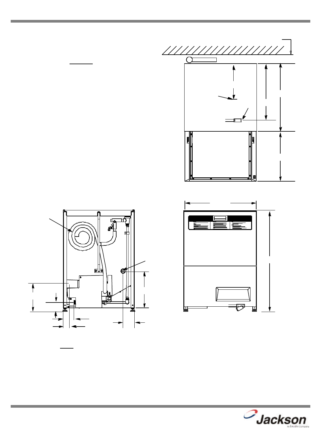
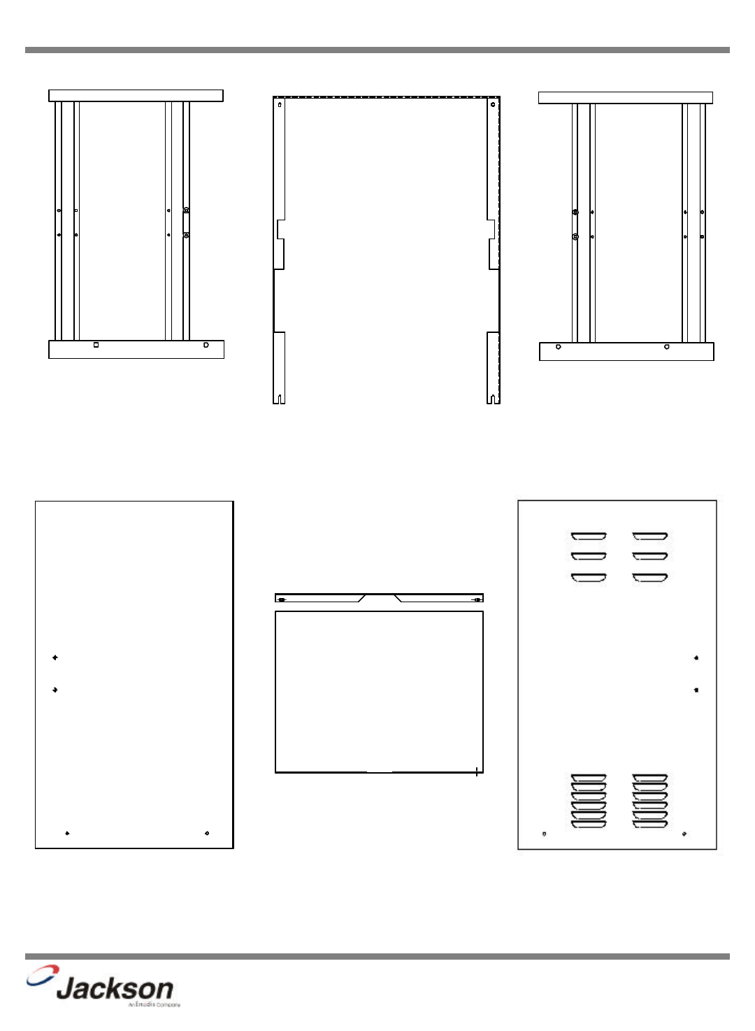
DIMENSIONS
Note: All dimensions from floor can be increased 1” with adjustable feet supplied.
DIMENSIONS
Height (minimum): 33-1/4” Inside Clearance Height: 14-1/2”
Height (maximum): 34-1/4” Inside Clearance Width: 20-1/4”
Width: 24-1/4” Inside Clearance Depth: 21-1/4”
Depth: 22-5/8” Door Open Depth: 39-1/2”
Wall Clearance (minimum): 2-1/2”
Legend:
A- Drain Connection flexible hose.
6’-0” free length, 1” ID x 1 3/8” OD
B- Electrical Connection.
C- Water Inlet 1/2” Female Pipe Thread, 2
1/2” AFF
D- Detergent Feeder Connection
MIN. WALL
CLEARANCE
D
A
B
C
C
33 3/4”
16 3/4”
22 5/8”
2 1/2”
19”
12”
24 1/4”
13 1/4”
8 1/2”
3 3/4”
2 1/4”
4 1/4”
2 3/4”

4
SECTION 2:
INSTALLATION/OPERATION
INSTRUCTIONS
5
JP-24BPNSU Technical Manual
7610-002-38-50 Rev. D (11/11/2005)
SECTION 2: INSTALLATION/OPERATION INSTRUCTIONS
INSTALLATION INSTRUCTIONS
VISUAL INSPECTION: Before installing the unit, check the container and machine for damage. A damaged container is an indi-
cator that there may be some damage to the machine. If there is damage to both the container and machine, do not throw away
the container. The dishmachine has been inspected and packed at the factory and is expected to arrive to you in new, undam-
aged condition. However, rough handling by carriers or others may result in there being damage to the unit while in transit. If
such a situation occurs, do not return the unit to Jackson; instead, contact the carrier and ask them to send a representative to
the site to inspect the damage to the unit and to complete an inspection report. You must contact the carrier within 48 hours of
receiving the machine. Also, contact the dealer through which you purchased the unit.
UNPACKING THE DISHMACHINE: Once the machine has been removed from the container, ensure that there are no miss-
ing parts from the machine. This may not be obvious at first. If it is discovered that an item is missing, contact Jackson imme-
diately to have the missing item shipped to you.
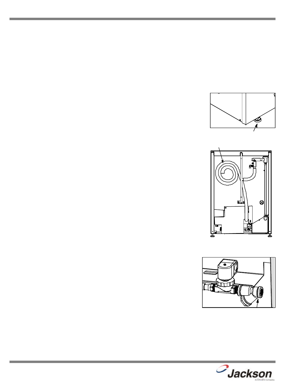
LEVEL THE DISHMACHINE: The dishmachine is designed to operate while being level.
This is important to prevent any damage to the machine during operation and to ensure the
best results when washing ware. The unit comes with adjustable bullet feet, which can be
turned using a pair of channel locks or by hand if the unit can be raised safely. Ensure that
the unit is level from side to side and from front to back before making any connections.
PLUMBING THE DISHMACHINE: All plumbing connections must comply with all applicable
local, state, and national plumbing codes. The plumber is responsible for ensuring that the
incoming water line is thoroughly flushed prior to connecting it to any component of the dish-
machine. It is necessary to remove all foreign debris from the water line that may potential-
ly get trapped in the valves or cause an obstruction. Any valves that are fouled as a result
of foreign matter left in the water line, and any expenses resulting from this fouling, are not
the responsibility of the manufacturer.
CONNECTING THE DRAIN LINE: The drain for the JP-24BPNSU is a pumped (pressure)
drain capable of pumping waste water to a height of 24 inches from the floor to the kitchen’s
drain system. The dishmachine is supplied with a 10 foot long hose that extends from the
rear side of the machine. There must also be an air gap between the machine drain line
and the floor sink or drain. If a grease trap is required by code, it should have a flow capac-
ity of 12 gallons per minute.
WATER SUPPLY CONNECTION: Ensure that you have read the section entitled “PLUMB-
ING THE DISHMACHINE” above before proceeding. Install the water supply line (1/2” pipe
size minimum) to the dishmachine line strainer using copper pipe. It is recommended that a
water shut-off valve be installed in the water line between the main supply and the machine
to allow access for service.
The water supply line is to be capable of 20 A5PSI “flow” pressure at the recommended
temperature indicated on the data plate.
In areas where the water pressure fluctuates or is greater than the recommended pressure,
it is recommended that a water pressure regulator be installed.
Do not confuse static pressure with flow pressure. Static pressure is the line pressure in a
“no flow” condition (all valves and services are closed). Flow pressure is the pressure in the
fill line when the fill valve is opened during the cycle.
It is also recommended that a shock absorber (not supplied with the JP-24BPNSU model)
be installed in the incoming water line. This prevents line hammer (hydraulic shock), induced by the solenoid valve as it oper-
ates, from causing damage to the equipment.
PLUMBING CHECK: Slowly turn on the water supply to the machine after the incoming fill line and the drain line have been
installed. Check for any leaks and repair as required. All leaks must be repaired prior to placing the machine in operation.
Adjustable Bullet Foot
Incoming Plumbing Y-Strainer
Back of Machine Showing Drain Hose
Drain Hose
6
JP-24BPNSU Technical Manual
7610-002-38-50 Rev. D (11/11/2005)
ELECTRICAL POWER CONNECTION: Electrical and grounding connections must comply with the applicable portions of the
National Electrical Code ANSI/NFPA 70 (latest edition) and/or other electrical codes.
Disconnect electrical power supply and place a tag at the disconnect switch to indicate that you are working on the circuit.
The dishmachine data plate is located on the right side and to the front of the machine. Refer to the data plate for machine
operating requirements, machine voltage, total amperage load and serial number.
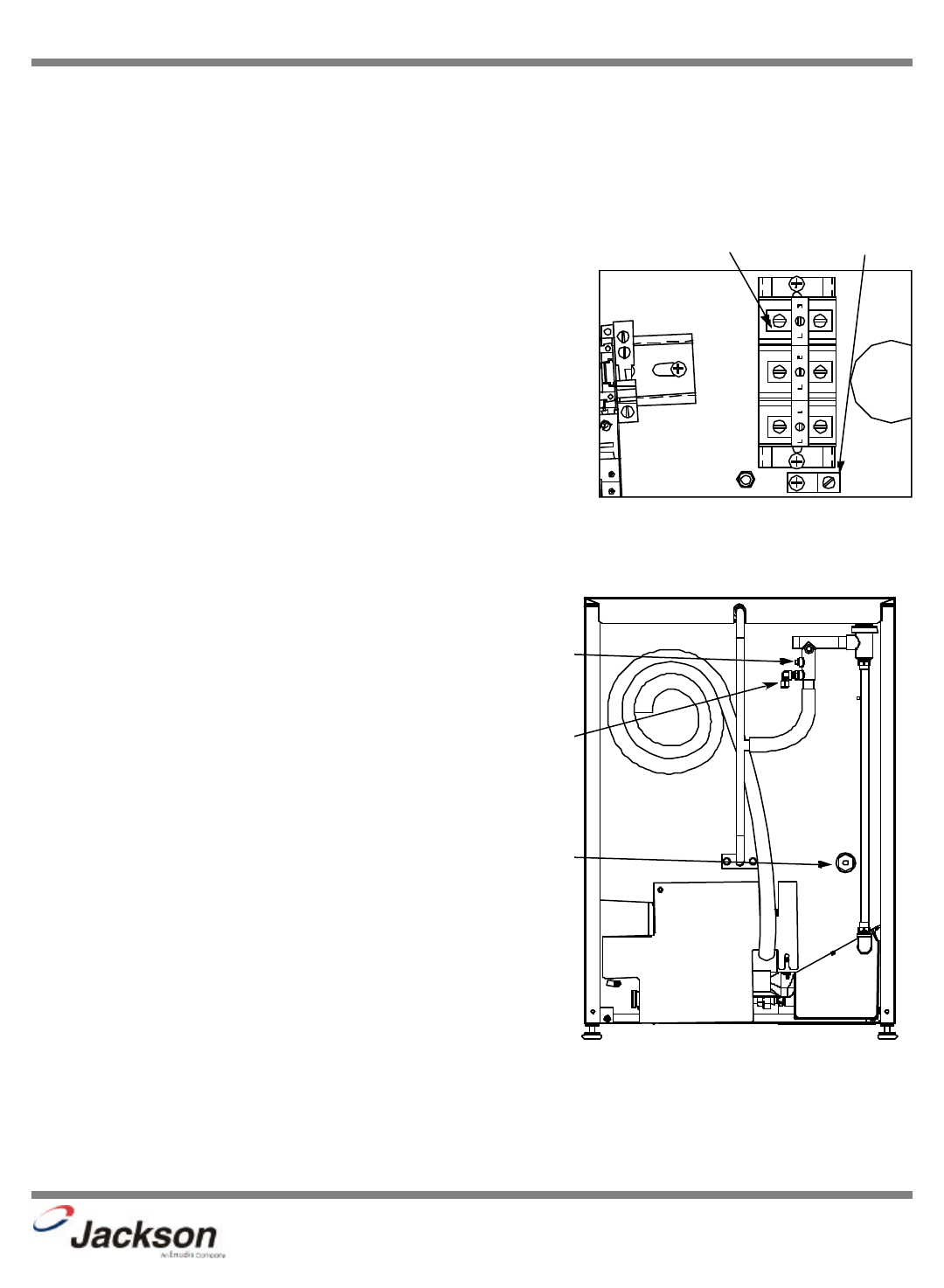
To install the incoming power lines, remove the kick panel. This will require tak-
ing a phillips head screwdriver and removing the four(4) screws on the front
cover of the kick plate. Install 3/4” conduit into the pre-punched holes in the
back of the control box. Route power wires and connect to power block and
grounding lug. Install the service wires (L1, L2 and L3) to the appropriate ter-
minals as they are marked on the terminal block. Install the grounding wire into
the lug provided. Tighten the connections and perform the “pull test”. The tight-
ened wires should remain in place after giving the wires a moderate pull to see
if they will come loose.
It is recommended that “DE-OX” or another similar anti-oxidation agent be
used on all power connections.
VOLTAGE CHECK: Ensure that the power switch is in the
OFF position and apply power to the dishmachine. Check
the incoming power at the terminal block and ensure it cor-
responds to the voltage listed on the data plate. If not, con-
tact a qualified service agency to examine the problem. Do
not run the dishmachine if the voltage is too high or too
low. Shut off the service breaker and mark it as being for
the dishmachine. Advise all proper personnel of any prob-
lems and of the location of the service breaker. Replace
the control box cover and tighten down the screws.
CHEMICAL CONNECTIONS: All chemical hookup loca-
tions are located on the back of the dishmachine. Please
refer to the drawing at the right for the correct connection
point.
This equipment is not recommend for use with deion-
ized water or other aggressive fluids. Use of deion-
ized water or other aggressive fluids will result in cor-
rosion and failure of materials and components. Use
of deionized water or other aggressive fluids will void
the manufacturer's warranty.
SECTION 2: INSTALLATION/OPERATION INSTRUCTIONS
ELECTRICAL INSTALLATION INSTRUCTIONS
Control Box Electrical Connection
Ground LugTerminal Block
Back of Unit Showing Chemical Connection Points
Rinse Aid Fitting
Brass Plug
Detergent Fitting
7
SECTION 2: INSTALLATION & OPERATION INSTRUCTIONS
INSTALLATION INSTRUCTIONS (CONTINUED)
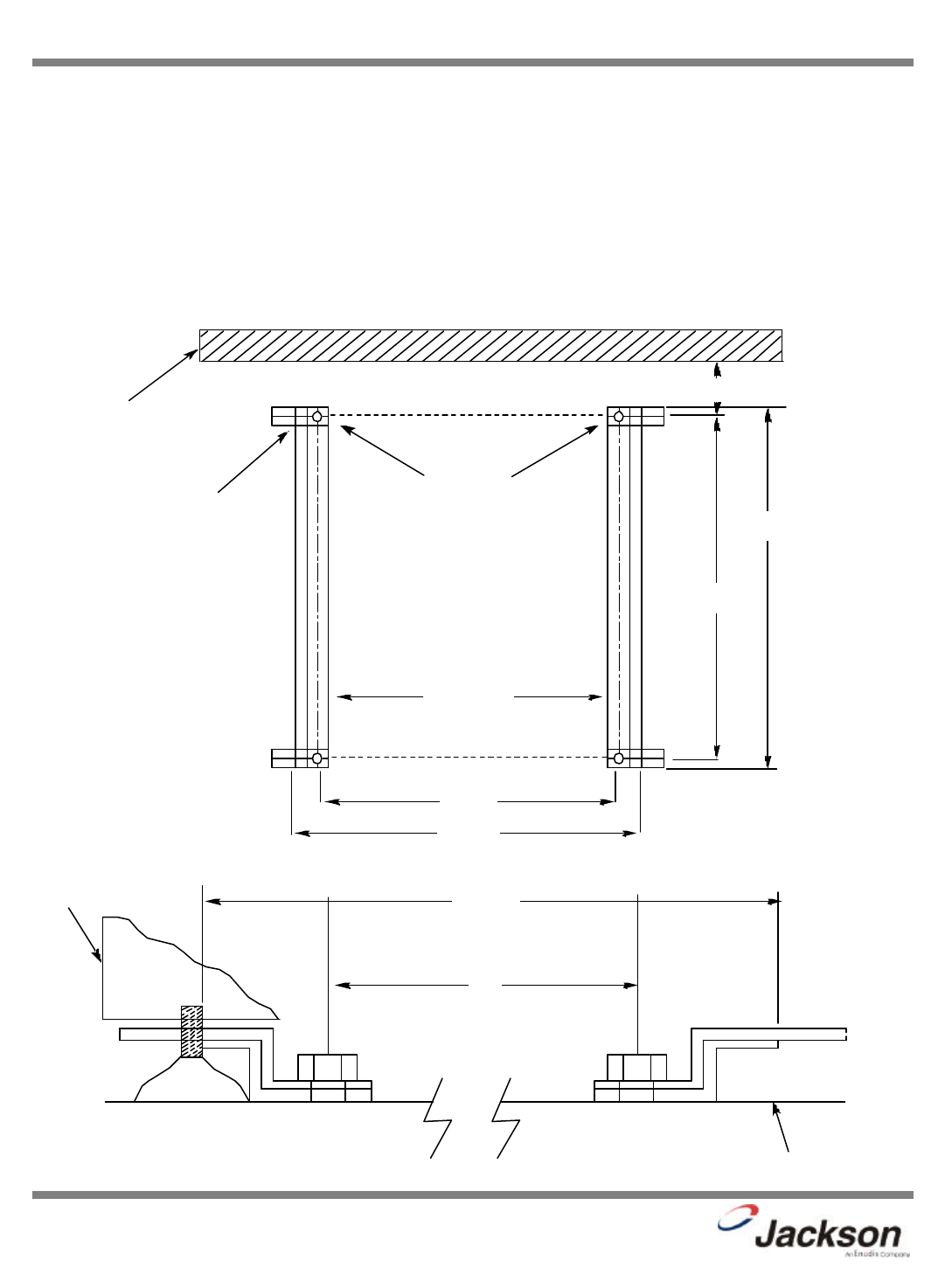
DECK MOUNTING OF THE DISHMACHINE: The dishmachine must be secured in place using the deck mounting tracks and
caps provided with machine. Install the (4) adjustable feet provided into screw holes where shipping bolts were removed earli-
er. Adjust the level of the dishmachine by screwing the adjustable feet in or out. The front of the machine should be adjusted
1/4” to 1/2” higher than the back. Install the deck mounting hardware as shown in the drawing below, at the location where the
dishmachine will be permanently positioned. Install 3/8” stainless steel lug bolts to secure tracks and caps to the deck. Drill
holes into deck as shown below and insure rear holes are located 2-1/4” from the wall. The racks and rear end caps may be
tightened at this time. Slide dishmachine onto tracks and into position at rear end caps. Install front end caps into place and
adjust if necessary to remove any movement of machine; if possible, tack weld tracks to deck.
JP-24BPNSU Technical Manual
7610-002-38-50 Rev. D (11/11/2005)
TYPICAL
LOCATION
OF FOOT
LEVELER
EXISTING WALL
19”
21 7/8”
21 1/4”
22 3/4”
2 1/4”
TOP VIEW
REAR
END CAPS
FRONT VIEW
19”
TYPICAL
LOCATION
OF FOOT
LEVELER
FRONT PANEL
OF DISHWASHER 21 7/8”
FLOOR

8
SECTION 2: INSTALLATION & OPERATION INSTRUCTIONS
DETERGENT CONTROL
Detergent usage and water hardness are two factors that contribute greatly to how efficient your dishmachine will operate.
Using detergent in the proper amount can become, in time, a source of substantial savings. A qualified water treatment spe-
cialist can tell you what is needed for maximum efficiency from your detergent, but you should still know some basics so you’ll
understand what they are talking about.
First, you must understand that hard water greatly effects the performance of the dishmachine. Water hardness is the amount
of dissolved calcium and magnesium in the water supply. The more dissolved solids in the water, the greater the water hard-
ness. Hard water works against detergent, thereby causing the amount of detergent required for washing to increase. As you
use more detergent, your costs for operating the dishmachine will increase and the results will decrease. The solids in hard
water also may build-up as a scale on wash and rinse heaters, decreasing their ability to heat water. Water temperature is
important in removing soil and sanitizing dishes. If the water cannot get hot enough, your results may not be satisfactory. This
is why Jackson recommends that if you have installed the machine in an area with hard water, that you also install some type
of water treatment equipment to help remove the dissolved solids from the water before it gets to the dishmachine.
Second, hard water may have you adding drying agents to your operating cycle to prevent spotting, when the real problem is
deposited solids on your ware. As the water evaporates off of the ware, the solids will be left behind to form the spotting and
no amount of drying agent will prevent this. Again, using treated water will undoubtedly reduce the occurrences of this prob-
lem.
Third, treated water may not be suitable for use in other areas of your operation. For instance, coffee made with soft water may
have an acid or bitter flavor. It may only be feasible to install a small treatment unit for the water going into the dishmachine
itself. Discuss this option with your qualified water treatment specialist.
Even after the water hardness problems have been solved, there still must be proper training of dishmachine operators in how
much detergent is to be used per cycle. Talk with your water treatment specialist and detergent vendor and come up with a
complete training program for operators. Using too much detergent has as detrimental effects as using too little. The proper
amount of detergent must be used for job. It is important to remember that certain menu items may require extra detergent by
their nature and personnel need to be made aware of this. Experience in using the dishmachine under a variety of conditions,
along with good training in the operation of the machine, can go a long way in ensuring your dishmachine operates as effi-
ciently as possible.
Certain dishmachine models require that chemicals be provided for proper operation and sanitization. Some models even
require the installation of third-party chemical feeders to introduce those chemicals to the machine. Jackson does not recom-
mend or endorse any brand name of chemicals or chemical dispensing equipment. Contact your local chemical distributor for
questions concerning these subjects.
Some dishmachines come equipped with integral solid detergent dispensers. These dispensers are designed to accommodate
detergents in a certain sized container. If you have such a unit, remember to explain this to your chemical distributor upon first
contacting them.
As explained before, water temperature is an important factor in ensuring that your dishmachine functions properly. The data
plate located on each unit details what the minimum temperatures must be for either the incoming water supply, the wash tank
and the rinse tank, depending on what model of dishmachine you have installed. These temperatures may also be followed by
temperatures that Jackson recommends to ensure the highest performance from you dishmachine. However, if the minimum
requirements are not met, the chances are your dishes will not be clean or sanitized. Remember, a dish can look clean, but it
may not be sanitized. Instruct your dishmachine operators to observe the required temperatures and to report when they fall
below the minimum allowed. A loss of temperature can indicate a much larger problem such as a failed heater or it could also
indicate that the hot water heater for your operation is not up to capacity and a larger one may need to be installed.
There are several factors to consider when installing your dishmachine to ensure that you get the best possible results from it
and that it operates at peak efficiency for many years. Discuss your concerns with your local chemical distributor and water
treatment specialist before there is a problem.
JP-24BPNSU Technical Manual
7610-002-38-50 Rev. D (11/11/2005)

9
SECTION 2: INSTALLATION & OPERATION INSTRUCTIONS
OPERATION INSTRUCTIONS
PREPARATION: Before proceeding with the start-up of the unit, verify the following:
1. The strainer is in place and is clean.
2. That the wash and rinse arms are screwed securely into place and that their endcaps are tight. The wash and rinse
arms should rotate freely.
POWER UP: To energize the unit, turn on the power at the service breaker. The voltage should have been previously verified
as being correct. If not, the voltage will have to be verified.
FILLING THE WASH TUB:For the initial fill, close the door and depress the ON/FILL-OFF/DRAIN rocker switch in the ON posi-
tion. The machine will run a partial cycle and fill to the factory preset level. Open the door and verify that the water level is
correct. Hereafter, the water level is controlled by the timer that has been preset at the factory. Verify that there are no other
leaks on the unit before proceeding any further. The wash tub must be completely filled before operating the wash pump to pre-
vent damage to the component. Once the wash tub is filled, the unit is ready for operation.
NOTE: Make sure the orange wires at the heater contactor are connected properly. They have been purposely disconnected
at the factory to avoid damage to the heater element when there is no water in the booster heater.
The machine runs a complete cycle to drain and fill. If the machine is not allowed to drain, the water will build up inside the
tub. After the initial fill, the rinse water for the current cycle will become the wash water for the next cycle.
WARE PREPARATION: Proper preparation of ware will help ensure good results and less re-washes. If not done properly, ware
may not come out clean and the efficiency of the dishmachine will be reduced. It is important to remember that a dishmachine
is not a garbage disposal and that simply throwing unscraped dishes into the machine simply defeats the purpose altogether
of washing the ware. Scraps should be removed from ware prior to being loaded into a rack. Pre-rinsing and pre-soaking are
good ideas, especially for silverware and casserole dishes. Place cups and glasses upside down in racks so that they do not
hold water during the cycle. The dishmachine is meant not only to clean, but to sanitize as well, to destroy all of the bacteria
that could be harmful to human beings. In order to do this, ware must be properly prepared prior to being placed in the machine.
DAILY MACHINE PREPARATION: Refer to the section entitled “PREPARATION” at the top of this page and follow the instruc-
tions there. Afterwards, check that all of the chemical levels are correct and/or that there is plenty of detergent available for the
expected workload.
WARM-UP CYCLES: For a typical daily start-up, it is recommended to run the machine through 3 cycles to ensure that all of
the cold water is out of the system and to verify that the unit is operating correctly. To cycle the machine, ensure that the power
is on and that the tub has filled to the correct level. Open the door and the cycle light will illuminate. When the light goes out,
close the door, the unit will start, run through the cycle, and shut off automatically. Repeat this two more times. The unit should
now be ready to proceed with the washing of ware.
WASHING A RACK OF WARE: To wash a rack, open the door completely and slide the rack into the unit. Close the door and
the unit will start automatically. Once the cycle is completed, open the door and remove the rack of clean ware. Replace with
a rack of soiled ware and close the door. The process will then repeat itself.
OPERATIONAL INSPECTION: Based upon usage, the pan strainer may become clogged with soil and debris as the workday
progresses. Operators should regularly inspect the pan strainer to ensure it has not become clogged. If the strainer does, it will
reduce the washing capability of the machine. Instruct operators to clean out the pan strainer at regular intervals or as required
by work load.
SHUTDOWN AND CLEANING: At the end of the workday, close the door. Start a cycle, then place the ON/FILL - OFF/DRAIN
SWITCH to the “ OFF/DRAIN” position. The unit will automatically drain and turn off. Once the wash tub is drained, remove he
pan strainer. Remove soil and debris from the strainer and set to the side. Unscrew the wash and rinse arms from their mani-
folds. Remove the endcaps and flush the arms with water. Use a brush to clean out the inside of the arms. If the nozzles appear
to be clogged, use a toothpick to remove the obstruction. Wipe the inside of the unit out, removing all soil and scraps.
Reassemble the wash and rinse arms and replace them in the unit. The arms only need to be hand tight, do not use tools to
tighten them down. Reinstall the strainer and close the door.
JP-24BPNSU Technical Manual
7610-002-38-50 Rev. D (11/11/2005)

10
SECTION 3:
PREVENTATIVE MAINTENANCE

JP-24BPNSU Technical Manual
7610-002-38-50 Rev. D (11/11/2005)
SECTION 3: PREVENTATIVE MAINTENANCE
PREVENTATIVE MAINTENANCE
The dishmachines covered in this manual are designed to operate with a minimum of interaction with the operator. However,
this does not mean that some items will not wear out in time.
There are many things that operators can do to prevent catastrophic damage to the dishmachine. One of the major causes of
component failure has to do with prescrapping procedures. A dishmachine is not a garbage disposal; any large pieces of mate-
rial that are put into the machine shall remain in the machine until they are either broken up (after spreading out on your ware!)
or physically removed. Strainers are installed to help catch debris, but they do no good if they are clogged. Have operators reg-
ularly inspect the pan strainers to ensure (1) that they are free of soil and debris and (2) they are laying flat in the tub.
When cleaning out strainers, do NOT beat them on waste cans. The strainers are made of metal and can be forgiving; but once
severe damage is done, it is next to impossible for the strainer to work in the way it was designed to. Wipe out strainers with
a rag and rinse under a faucet if necessary. For stubborn debris, a toothpick should be able to dislodge any obstructions from
the perforations. Always ensure that strainers are placed back in the machine before operation and that they lay flat in the tub.
You may wish to contact Jackson in order to learn more about how your water hardness will effect the performance of your
machine. Hard water makes dishmachines work harder and decreases efficiency.
Again, it is important to remind operators that trying to perform corrective maintenance on the dishmachine could lead to larg-
er problems or even cause harm to the operator. If a problem is discovered; secure the dishmachine using proper shut down
procedures as listed in this manual and contact Jackson.
Some problems, however, may having nothing to do with the machine itself and no amount of preventative maintanence is
going to help. A common problem has to do with temperatures being too low. Verify that the water temperatures coming to your
dishmachine match the requirements listed on the machine data plate. There can be a variety of reasons why your water tem-
perature could be too low and you should discuss it with Jackson to determine what can be done.
By following the operating and cleaning instructions in this manual, you should get the most efficient results from your machine.
As a reminder, here are some steps to take to ensure that you are using the dishmachine the way it was designed to work:
1. Ensure that the water temperatures match those listed on the machine data plate.
2. Ensure that all strainers are in place before operating the machine.
3. Ensure that all wash and/or rinse arms are secure in the machine before operating.
4. Ensure that drains are closed/sealed before operating.
5. Remove as much soil from dishes by hand as possible before loading into racks.
6. Do not overfill racks.
7. Ensure that glasses are placed upside down in the rack.
8. Ensure that all chemicals being injected to machine have been verified as being at the correct concentrations.
9. Clean out the machine at the end of every workday as per the instructions in the manual.
10. Always contact your Ecolab representative whenever a serious problem arises.
11. Follow all safety procedures, whether listed in this manual or put forth by local, state or national codes/regulations.
11

12
SECTION 4:
TROUBLESHOOTING

13
SECTION 4: TROUBLESHOOTING SECTION
COMMON PROBLEMS
WARNING: Inspection, testing and repair of electrical equipment should be performed only by qualified service person-
nel. Certain procedures in this section require electrical tests or measurements while power is applied to the machine.
Exercise extreme caution at all times. If test points are not easily accessible, disconnect power, attach test equipment and
reapply power to test. When replacing electrical parts, disconnect power at source circuit breaker.
Problem: Water overflow from bottom of door.
1. Clogged drain. Remove obstruction.
2. Machine not level. Level machine, or increase height to the front.
3. Excessive inlet pressure. Install pressure reducing valve, or adjust if one is present. Ensure flow is 20 PSI.
4. Detergent foaming. Reduce detergent quantity.
Problem: Wash motor doesn’t operate on manual wash.
1. Loose or broken wires. Reconnect or replace wires in motor.
2. Defective manual wash switch. Replace.
3. Defective motor starting relay. Replace.
Problem: Motor operates on manual wash but not on automatic.
1. Defective timer. Replace timer.
2. Defective circuit in manual wash switch. Replace switch.
Problem: No water comes through the rinse arms when the “ON/FILL” switch is depressed.
1. Water not turned on. Turn water on.
2. Defective solenoid valve. Replace solenoid valve.
3. Probes are dirty or coated. Clean probes.
4. Defective water level control. Replace.
Problem: Little or no water coming through the rinse assemblies.
1. Limed up rinse heads or piping. Delime rinse heads.
2. Low water pressure. Increase pipe size to machine. Adjust pressure regulator.
Problem: Rinse water runs continuously with breaker turned off.
1. Defective plunger in solenoid valve. Replace.
2. Defective diaphragm in solenoid valve. Replace diaphragm.
Problem: Rinse doesn’t operate on automatic during timed cycle (but does operate in auto/fill operation).
1. Timer defective. Replace timer.
Problem: Rinse water runs continuously with power applied to machine, but when circuit breaker to machine is turned
off, water stops.
1. Defective water level control. Replace.
2. Probes are dirty or coated. Clean probes.
Problem: Wash temperature not at required reading on thermometer.
1. Defective thermometer. Replace.
2. Defective thermostat. Adjust thermostat. Replace thermostat.
3. Rinse heater defective. Replace heater element.
4. Water level protection control device. Replace.
JP-24BPNSU Technical Manual
7610-002-38-50 Rev. D (11/11/2005)

14
SECTION 4: TROUBLESHOOTING SECTION
COMMON PROBLEMS
Problem: Rinse water not at required temperature range.
1. Thermometer is defective. Replace.
2. Thermostat is defective. Adjust the thermostat. Replace if necessary.
Problem: Machine doesn’t drain when “OFF/DRAIN” switch is pressed.
1. Drain solenoid clogged. Remove obstruction.
2. Defective “OFF/DRAIN” switch. Replace.
3. Defective motor or motor start relay. Replace.
4. Defective drain solenoid. Replace.
5. Defective timer. Replace.
Problem: No indication of pressure.
1. Water turned off. Turn water on.
2. 1/4” test cock ball valve is closed. Open the ball valve.
JP-24BPNSU Technical Manual
7610-002-38-50 Rev. D (11/11/2005)

15
SECTION 5:
SERVICE PROCEDURES
16
JP-24BPNSU Technical Manual
7610-002-38-50 Rev. D (11/11/2005)
SECTION 5: SERVICE PROCEDURES
RINSE SOLENOID VALVE REPAIR PARTS KIT
These dishmachines are equipped with electrical
solenoid valves to allow for automatic fill and rinse. These
valves are designed to specific tolerances and design aspects
that must be met in order to function properly.
Jackson offers repair kits for replacing some of the
wear items associated with solenoid valves which will allow
you to save money in that replacement of these parts can take
place without removing the solenoid valve from the plumbing
assembly.
The instructions provided here are for maintenance
personnel only. Unauthorized persons should not attempt any
of the steps contained in these instructions.
Warning: many of the instructions and steps
within this document require the use of tools. Only autho-
rized personnel should ever perform any maintenance
procedure on the dishmachine!
PREPARATION
1. Power must be secured to the unit at the service
breaker. Tag or lock out the service breaker to prevent acci-
dental or unauthorized energizing of the machine.
2. Ensure that incoming water to the machine is
secured either by use of a shut-off valve or disconnecting the
incoming water line.
TOOLS REQUIRED
The following tools will be needed to perform this
maintenance evolution:
1. Small flathead screwdriver
2. Medium flathead screwdriver
2. Needle nose pliers
3. 5/16” nutdriver
4. Channel locks
5. 12” pipe wrench
TIME REQUIRED
It is estimated that it will take (1) person twenty min-
utes to perform this task, not including all of the items indicat-
ed in the section entitled “PREPARATION”.
IMPORTANT NOTES
1. Read these instructions thoroughly before attempt-
ing this maintenance evolution. Become familiar with the parts
and what actions need to be taken. This will save time in the
long run!
2. The procedures demonstrated in this manual are
shown being performed on an AJ-44C rack conveyor dishma-
chine. The actual maintenance steps, however, apply to any
Parker style solenoid valve found on a Jackson dishmachine.
STEPS
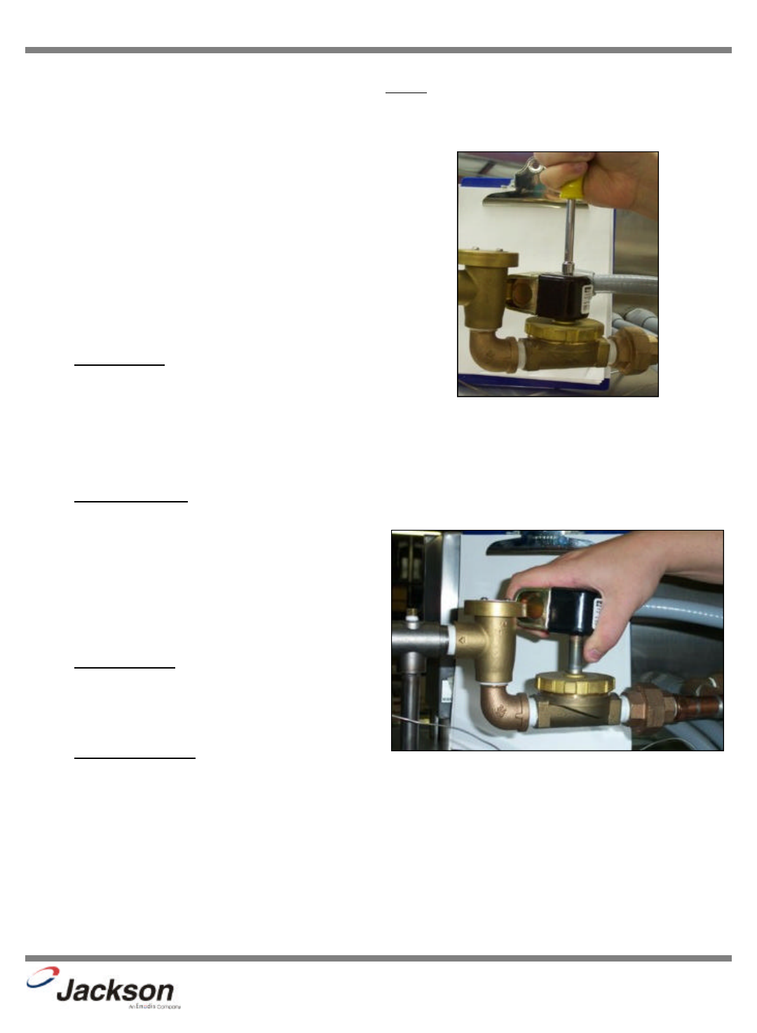
1. Remove the top screw with the 5/16” nutdriver. Remove the
screw and the data plate and set to the side.
2. With the top screw and data plate removed, grasp the sole-
noid coil and gently pull up. The coil should slide up, allowing
you to remove it from the valve bonnet. If you are wanting to
replace the coil, continue on with Step 3. If you are wanting to
replace some of the internal components of the valve, proceed
to step 12.
3. NOTE: Replacing the solenoid coil requires working with
the wiring of your machine. It is important that all wiring main-
tenance be performed by qualified personnel. Always verify
the wiring steps presented in this instruction with the schemat-
ic that shipped with the unit. A current schematic can also be
found in the unit’s installation manual. Before beginning any
step that involves working with wiring, ensure that the steps
located in the section entitled “Preparation” have been per-
formed. Power must be secured to the machine at the service
breaker. Failure to do so could result in severe injury to main-
tenance personnel.
Removing the top screw
Removing the coil
17
JP-24BPNSU Technical Manual
7610-002-38-50 Rev. D (11/11/2005)
SECTION 5: SERVICE PROCEDURES
RINSE SOLENOID VALVE REPAIR PARTS KIT (CONTINUED)
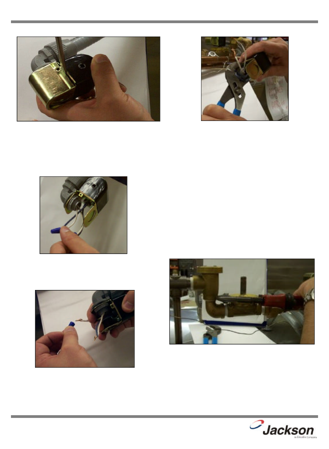
4. When replacing the coil, ensure that when removing the coil
wire cover that care is taken not to damage the wires inside.
Using the medium flathead screwdriver, gently use it to open
the cover enough to where it could be pulled off.
5. Once the coil wire cover has been removed and set to the
side, take the internal wires and pull them out straight.
6. Remove the wire nuts from the wires and separate them.
7. Using a pair of channel locks, gently loosen the conduit
retaining ring for the conduit nut. Once it is loosened, use your
fingers to unscrew and remove it.
8. Pull the conduit away and discard the bad coil. Take the
new coil and attach the conduit, reinstall & tighten the conduit
nut, and pull the wires through so that you will be able to wire
the valve back up.
9. Reconnect the wires from the conduit to the wires from the
solenoid as they had been connected previously. Ensure that
the wire nuts are on tight.
10. Slide the coil wire cover back on, taking care not to dam-
age the wires.
11. If you are done performing maintenance on the valve, con-
tinue on to step 23. Otherwise, please go on to step 12.L
12. To remove the valve bonnet, grasp it with the jaws of the
pipe wrench and turn to the left. Note: on some models you
may have to remove the valve in order to perform this and any
further steps. Be careful not to damage the plumbing assem-
bly. Only use the pipe wrench enough to where you can spin
the valve bonnet off with your hand.
Prying open the coil wire cover
Straightening the wires
Loosening the conduit nut
Removing the wire nuts
Loosening the valve bonnet
18
JP-24BPNSU Technical Manual
7610-002-38-50 Rev. D (11/11/2005)
SECTION 5: SERVICE PROCEDURES
RINSE SOLENOID VALVE REPAIR PARTS KIT (CONTINUED)
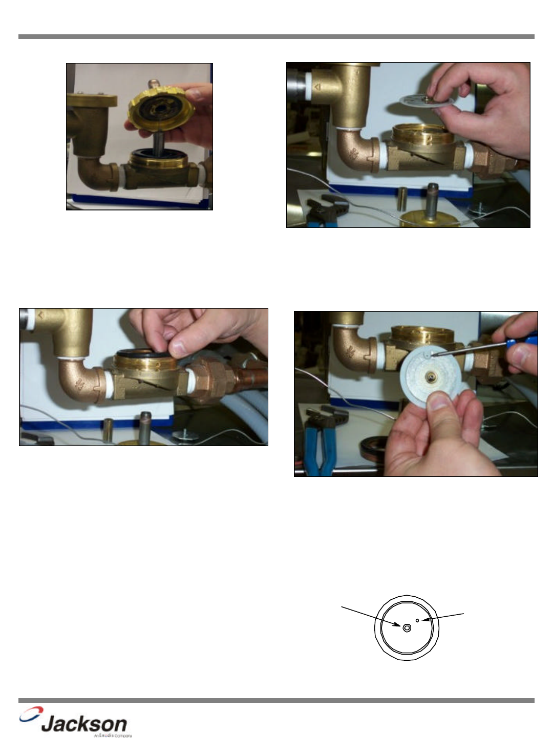
13. Slowly remove the valve bonnet. Note: The spring for the
plunger is located directly under the bonnet and may come
free if you are not careful. Remove the plunger, spring and
valve bonnet and place to the side.
14. Remove the O-ring and inspect it. If it has any tears or cuts
or excessive flat spaces, it should be replaced.
15. Examine the threads for the valve bonnet. Check them for
scoring or signs of damage. Take a cloth and clean them out
to remove any foreign particles that might get lodged in the
threads and cause a leak. Severely damage threads should
not be repaired; instead it is recommended that the entire
valve should be replaced. These instructions do not provide
information on replacing the solenoid valve.
16. Note: Even though an O-ring may not appear damaged, it
is a good idea to go ahead and replace it if you have a new
one. This will help ensure that your valve remains leak-free in
the future!
17. Remove the diaphragm retainer and then the diaphragm
itself. Many problems associated with a solenoid valve can be
traced to a clogged pilot port in the diaphragm.
18. As indicated in the photo above, the extension hole can
become clogged. If it is difficult to clean out, you can use a
heated straight pin to push through the hole. The center hole,
the pilot port, must also be clear. If the diaphragm is torn or
bent in any way, it must be replaced.
Removing the valve bonnet
Removing the O-ring
Removing the diaphragm
Pointing out the extension hole
2
1
Diaphragm showing (1) pilot port and (2) extension hole
19
JP-24BPNSU Technical Manual
7610-002-38-50 Rev. D (11/11/2005)
SECTION 5: SERVICE PROCEDURES
RINSE SOLENOID VALVE REPAIR PARTS KIT (CONTINUED)
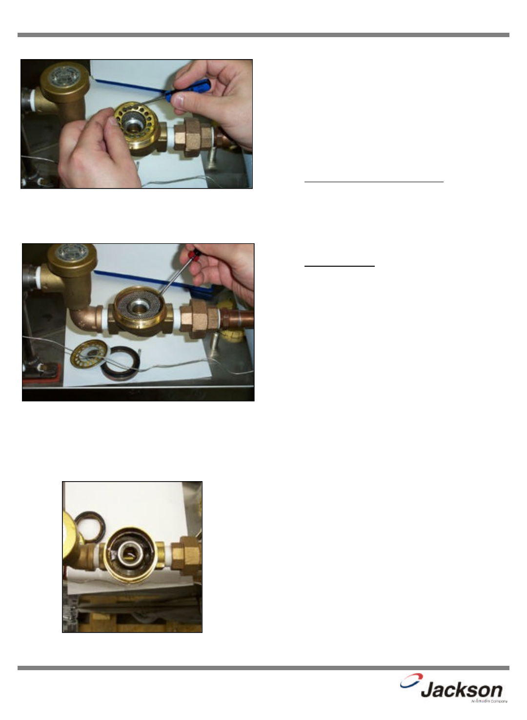
19. Using the small flathead screwdriver, lift out the screen
retainer. Verify that the holes in it are free of clogs and debris.
20. Again using the small flathead screwdriver, carefully
remove the mesh screen from inside the valve body. The
screen should be taken and rinsed out to remove any debris
fouling it.
21. With the mesh screen removed, look down into the valve
and verify it is not clogged. Remove any foreign objects from
the valve body that would obstruct flow.
22. Reassemble the valve, reversing the steps needed to take
it apart. Replace defective replacement parts with new parts
from ordered kits. Ensure that components are sufficiently
tightened to prevent leakage.
AFTER MAINTENANCE ACTIONS
Reconnect the incoming water (if disconnected) and
turn on. Then restore power to the unit. Run the unit for at
least 10 minutes to ensure there are no leaks. If any problems
arise please contact Jackson.
SPECIAL PARTS
Solenoid Valve Plunger Kit
Includes plunger and spring
Part number 06401-003-07-40
Solenoid Valve Diaphragm Kit
Includes diaphragm and o-ring
Part number 06401-003-07-41 (1/2” NPT)
Solenoid Valve 110 Volt Coil and Housing Kit
Part number 06401-003-07-43
Complete Solenoid Valve
Part number 04810-100-12-18 (1/2”, 110 Volt)
Removing the screen retainer
Removing the mesh strainer screen
View inside the solenoid valve body
20
JP-24BPNSU Technical Manual
7610-002-38-50 Rev. D (11/11/2005)
SECTION 5: SERVICE PROCEDURES
VACUUM BREAKER REPAIR PARTS KIT
These dishmachines are equipped with vacuum
breakers to serve as back-flow prevention devices. ASSE
requirements specify what type of back-flow prevention is nec-
essary on dishmachines. Vacuum breakers, unlike air gaps,
have certain parts that have specific tolerances and design
aspects that must be met in order to function properly.
Jackson offers repair kits for replacing some of the
wear items associated with vacuum breakers which will allow
you to save money in that replacement of these parts can take
place without removing the vacuum breaker from the plumb-
ing assembly.
The instructions provided here are for maintenance
personnel only. Unauthorized persons should not attempt any
of the steps contained in these instructions.
Warning: many of the instructions and steps
within this document require the use of tools. Only autho-
rized personnel should ever perform any maintenance
procedure on the dishmachine!
PREPARATION
1. Power must be secured to the unit at the service
breaker. Tag or lock out the service breaker to prevent acci-
dental or unauthorized energizing of the machine.
2. Ensure that incoming water to the machine is
secured either by use of a shut-off valve or disconnecting the
incoming water line.
TOOLS REQUIRED
The following tools will be needed to perform this
maintenance evolution:
1. Small flathead screwdriver
2. Needle nose pliers
TIME REQUIRED
It is estimated that it will take (1) person twenty min-
utes to perform this task, not including all of the items indicat-
ed in the section entitled “PREPARATION”.
IMPORTANT NOTES
1. Read these instructions thoroughly before attempt-
ing this maintenance evolution. Become familiar with the parts
and what actions need to be taken. This will save time in the
long run!
STEPS
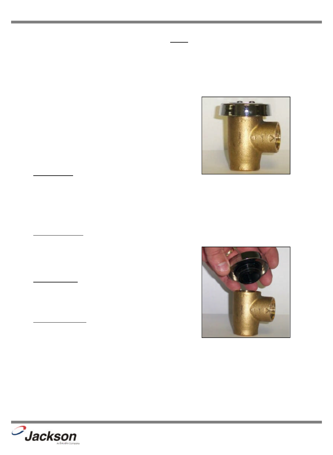
1. Note: These instructions only apply to vacuum breakers
(1/2” NPT and 3/4” NPT) as pictured below. The repair kits
indicated in these instructions will only work on those style of
back-flow preventers. If you have a machine with a different
style of vacuum breaker, contact your Ecolab representative
about replacement components.
2. Note: Even though the photos in these instructions show a
vacuum breaker that has been removed from the plumbing
assembly, these maintenance steps could be performed with it
installed so long as the requirements in the section entitled
“PREPARATION” have been met.
3. Remove the top cap by gripping firmly and turning to the
left. The cap should come off after a few turns.
4. Set the cap to the side.
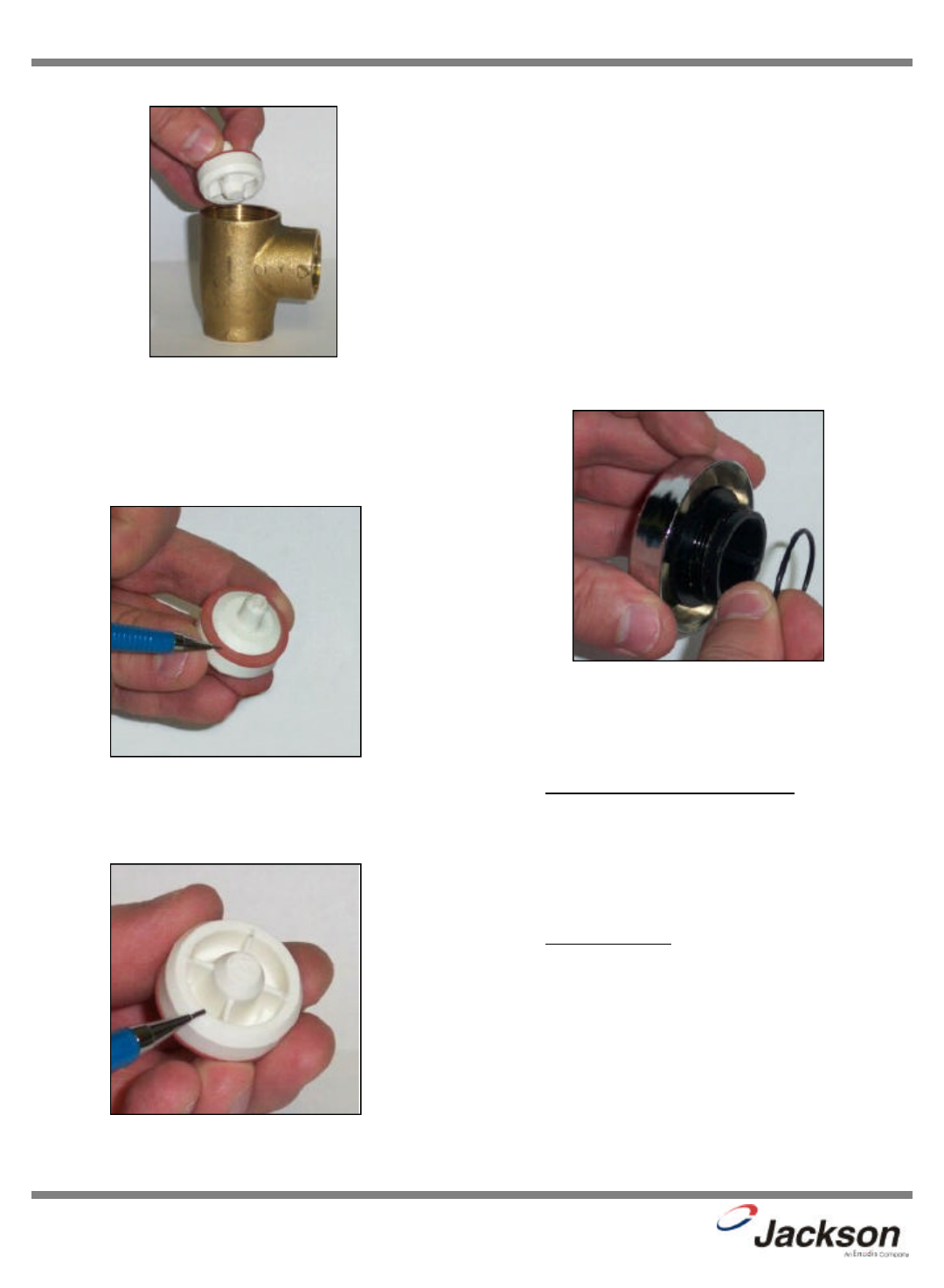
5. Using the needle nose pliers, gently lift out the plunger and
set to the side. Examine the brass seating surface inside the
vacuum breaker. The plunger is required to sit flat on this sur-
face so it must be free of defects, imperfections and the like. If
there is debris, remove it. If it is chipped or cracked then the
vacuum breaker must be replaced. Failure to do so may result
in the vacuum breaker not working according to its design and
could result in damage to the dishmachine.
Vacuum breaker
Removing the cap
21
JP-24BPNSU Technical Manual
7610-002-38-50 Rev. D (11/11/2005)
SECTION 5: SERVICE PROCEDURES
VACUUM BREAKER REPAIR PARTS KIT (CONTINUED)
6. Your repair kit comes with a new plunger. Examine the old
one and ensure that the mating surface is not damaged or cut.
Also inspect the rubber seal on the top of the plunger to
ensure it is in good condition and not torn.
7. If any of these conditions are present, replace the old
plunger with the new one from your kit. Verify that the new
plunger is also free from defects. If it is not, contact your
Ecolab representative immediately.
8. The plunger should drop into the vacuum breaker and seat.
Ensure it is not flipped upside down (the orange seal ring
should be up towards the top of the vacuum breaker).
9. Pick up the cap and examine it. With a soft towel, remove
any grit, grime or debris that may have gotten caught in the
threads of both the cap retainer or the vacuum breaker body.
There is an O-ring that should be present on the cap retainer
as well. Regardless of the condition of the plunger, this O-ring
should be replaced once the cap is removed. Using a small
flathead screwdriver, remove the old O-ring.
10. With the new O-ring in place, screw the cap back on the
vacuum breaker body. The cap needs to only be hand tight
(snug).
AFTER MAINTENANCE ACTIONS
1. Reconnect the incoming water (if disconnected)
and turn on. Then restore power to the unit. Run the unit for
at least 10 minutes to ensure there are no leaks. If any prob-
lems arise please contact Jackson.
SPECIAL PARTS
To order the kit with components and instructions:
Components of 1/2” Repair Kit
06401-003-06-23
Removing the plunger
Examining the seal ring on the plunger
Examining the plunger seating surface
Replacing the O-ring
22
SECTION 5: SERVICE PROCEDURES
REPLACING THE PUMP MOTOR/REPLACING THE HEATER
REPLACING THE PUMP MOTOR
The following list of tools will be needed to complete this procedure. 5/6” nutdriver, phillips screwdriver, 7/16” socket
and ratchet, and 7/16” wrench.
1. Disconnect the electrical power to the dishwasher at the main circuit breaker box when servicing. Place a tag on the cir-
cuit box indicating the circuit is being repaired.
2. Disconnect power and conduit from dishmachine terminal block.
3. Turn off the water supply and disconnect the water supply line.
4. Disconnect the dishmachine drain hose from the kitchen’s
drain. Drain the machine of any water at this time.
5. Move the machine out and lay machine onto its back.
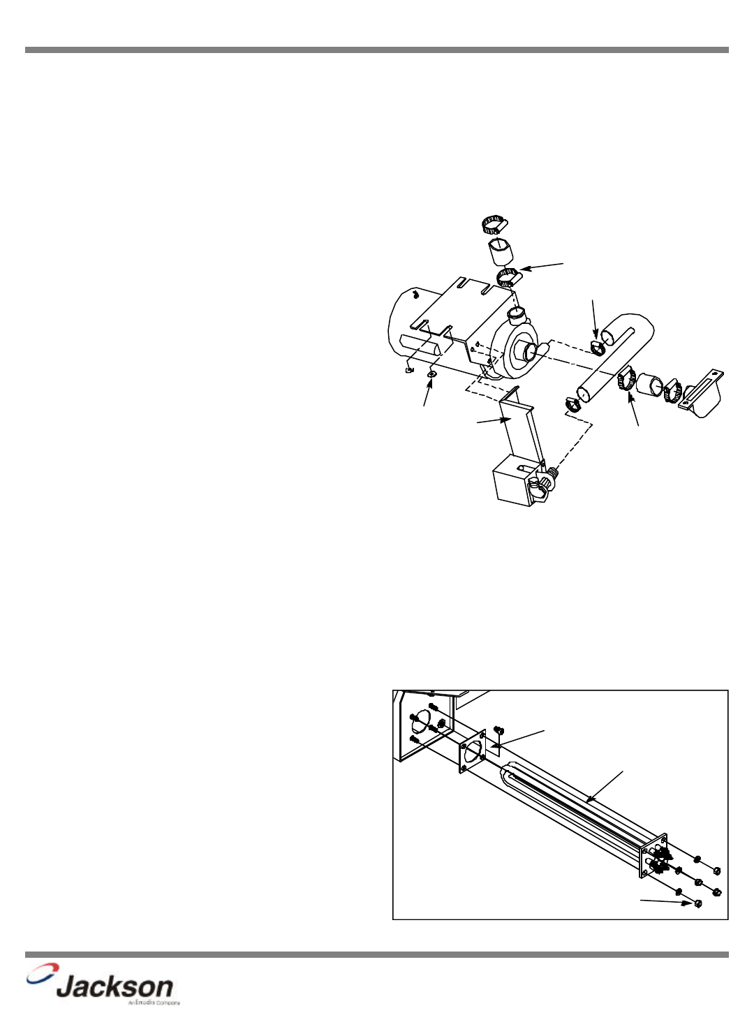
6. Use a 5/16” nutdriver to loosen the hose clamp and remove
the pump hose to the drain valve.
7. Use a 5/16” nutdriver to loosen the hose clamp and remove
the pump hose from the suction casting.
8. Use a 5/16” nutdriver to loosen the hose clamp and remove
the pump hose from the discharge hub casting.
9. Use a 7/16” socket and ratchet, and a 7/16” wrench to
remove the drain valve mounting bracket from the motor brack-
et.
10. Use a 7/16” socket and ratchet to remove the pump motor
assembly by loosening the (4) locknuts securing the motor
mounting bracket. NOTE: The motor mounting bracket is slot-
ted to allow for easy removal and installation. Remove (2) of the
locknuts on one side and slide the assembly toward that side
and remove. Once the assembly is removed, disconnect the
wire leads from the motor wiring box.
11. Install replacement motor in reverse order of above.
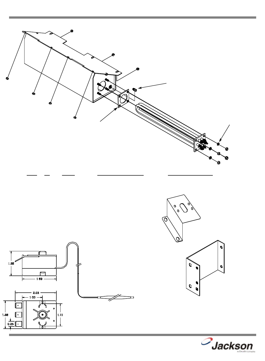
REPLACING THE BOOSTER TANK HEATER
The following list of tools will be needed to complete this procedure: phillips screwdriver and 1/2” socket and ratchet.
1. Disconnect the electrical power to the dishwasher at the main circuit breaker box when servicing. Place a tag on the cir-
cuit box indicating the circuit is being repaired.
2. Use the phillips screwdriver to remove the two screws from the bottom of the kick panel.
3. Disconnect power and conduit from dishmachine terminal block.
4. Turn off the water supply to the dishmachine.
5. VERY IMPORTANT: Disconnect wire lead (orange/white) from heater contactor coil. Note: Wire is tagged in electrical
panel.
6. Drain water from booster tank.
7. Remove the wires from the heater.
8. Use a 1/2” socket and ratchet to remove the (4) 5/16-18 hex
nuts and lock washers. Remove the heater and heater gasket
from booster tank.
8. Install the replacement heater and gasket, the tighten firmly.
9. Connect wire leads to heater and tighten firmly.
10. Turn on water supply and power to dishmachine.
11. Place cycle switch in AUTO position and depress power
switch to ON/FILL position.
12. VERY IMPORTANT: Run the dishmachine through several
complete cycles and check water level in wash sump. If there is
water in the wash sump, reconnect the wire lead (orange/white)
previously removed from the heater contactor coil.
13. Run the dishwasher through several cycles and check to see
that rinse and wash temperatures are correct.
JP-24BPNSU Technical Manual
7610-002-38-50 Rev. D (11/11/2005)
6
8
9
10
7
Replacing the Pump Motor
Heater Gasket
Heater
Hex Nuts & Washers
Replacing the Heater
23
SECTION 5: SERVICE PROCEDURES
REPLACING THE DRAIN VALVE
REPLACING THE DRAIN VALVE
The following list of tools will be needed to complete this procedure. 5/16” nutdriver, flat screwdriver, phillips screwdriver, and
7/16” socket and ratchet.
1. Disconnect the electrical power to the dishwasher at the main circuit breaker box when servicing. Place a tag on the cir-
cuit box indicating the circuit is being repaired.
2. Disconnect the power and conduit from dishmachine terminal block.
3. Turn off the water supply to the dishmachine.
4. Move the dishmachine away from the wall for servicing.
5. Use a 7/16” socket and ratchet to remove the lower enclosure panel at rear of machine.
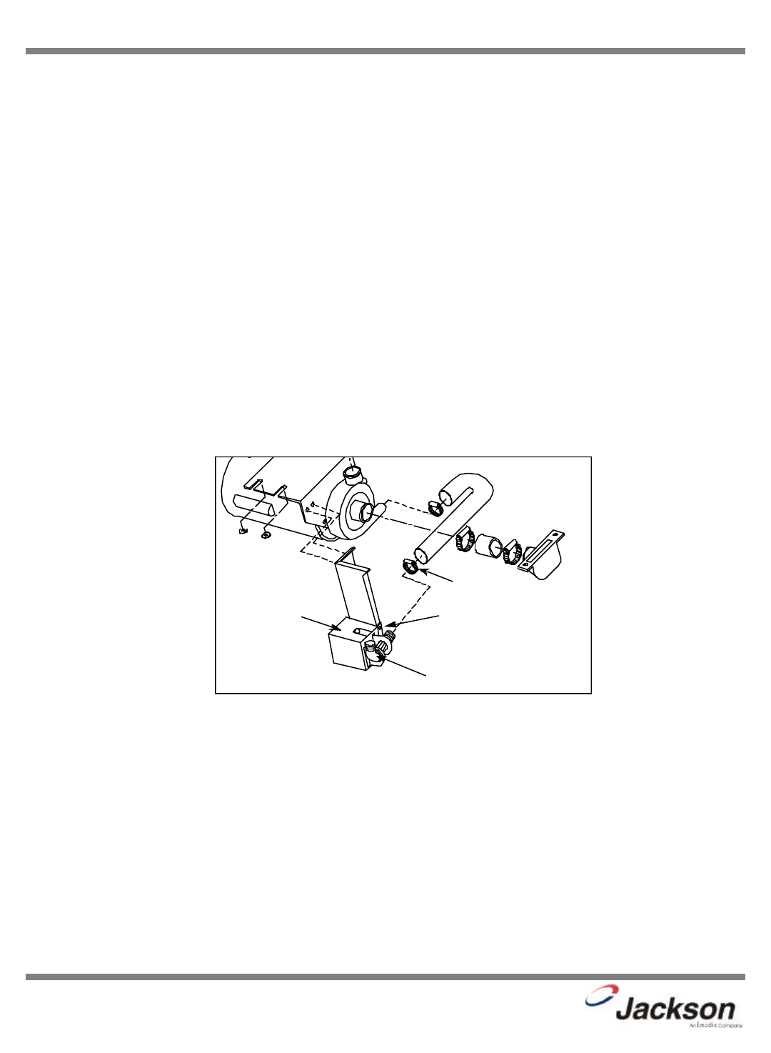
6. Drain the dishmachine. Siphon out the water or remove inlet hose to drain valve and drain into pan. The dishmachine
may be drained by opening the petcock on the pump housing or by removing the wash thermometer bulb from the lower wash
tank.
7. Use a 5/16” nutdriver to loosen the hose clamp and remove the inlet hose to the drain valve from the pump motor.
8. Use a phillips screwdriver to remove the cover from the valve. Use a flat screwdriver to disconnect the lead wires and
ground to the drain valve.
9. Use a 5/16” nutdriver to loosen the hose clamp and remove the discharge hose from the drain valve.
10. Use a phillips screwdriver to remove the screws attaching the drain valve to the mounting plate.
11. Reverse the procedures to install the new valve. INSURE GROUND WIRE LEAD IS CONNECTED PROPERLY TO TER-
MINAL ON THE MOTOR.
JP-24BPNSU Technical Manual
7610-002-38-50 Rev. D (11/11/2005)
7
9
108
Replacing the Drain Valve

24
SECTION 6:
PARTS SECTION
25
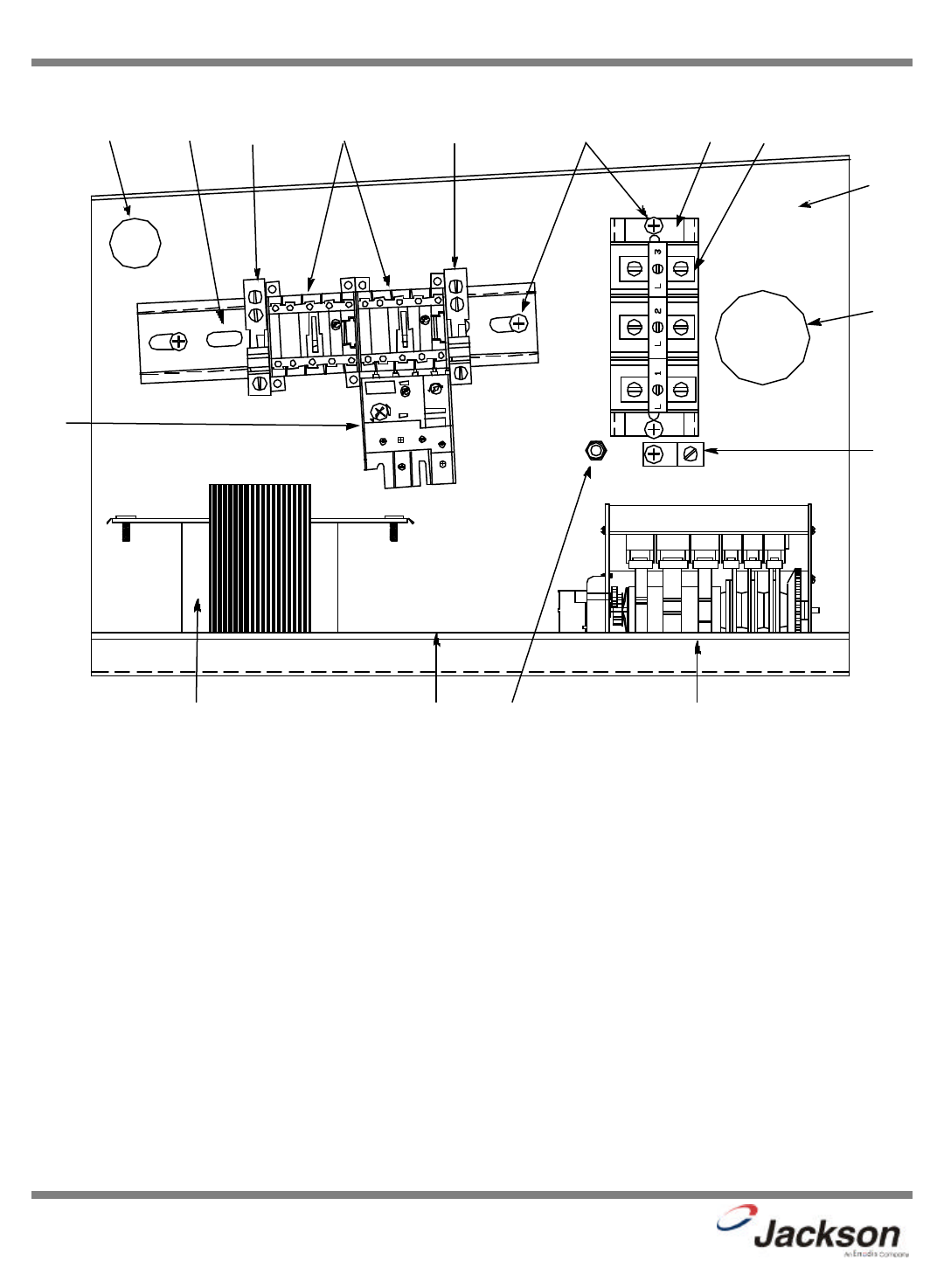
SECTION 6: PARTS SECTION
ELECTRICAL PANEL ASSEMBLY
ITEM QTY DESCRIPTION Mfg. No.
11Bushing, Snap 05975210-03-00
21Track, Terminal 6 7/8" 05700-021-62-91
32End Clamp 05940-111-60-30
42Contactor, Mini 05945111-60-07
59Screw, 10-32 x 3/8” Phillips Truss Round Head 05305-173-12-00
61Track, Terminal 3 3/4" 05700-011-62-89
71Decal, L1, L2, L3 09905-101-12-66
83Block, Snap-in Terminal 05940-500-02-19
91Electrical Control Panel Weldment 05700-031-62-94
10 1 Grommet, 1 1/8" Heyco 05975210-08-00
11 1Wire Lug 05940-200-76-00
12 1 Ground Decal 09905-011-41-82
13 1 Overload, Contactor 05945111-60-08
14 1 ACME Transformer, 480 to 120 Volt 05950-011-50-70
15 1 Terminal Board, 1/4 QC 05940-021-94-85
16 2 Screw, 6-32 x 3/8” Sems with External Tooth Lockwasher 05305-002-25-91
17 1 Locknut, 10-24 S/S Hex with Nylon Insert 05310-373-01-00
18 1 Timer, 6 Cam 05945121-44-69
19 1 Decal, Timer 09905-011-40-70
20 4 Locknut, 1/4”-20 S/S Hex with Nylon Insert (not shown) 05310-374-01-00
JP-24BPNSU Technical Manual
7610-002-38-50 Rev. D (11/11/2005)
7, 8
10
9
1
14, 5
13
15, 16
11, 12,
5
17 18, 19, 16
2 3 34 5 6
26
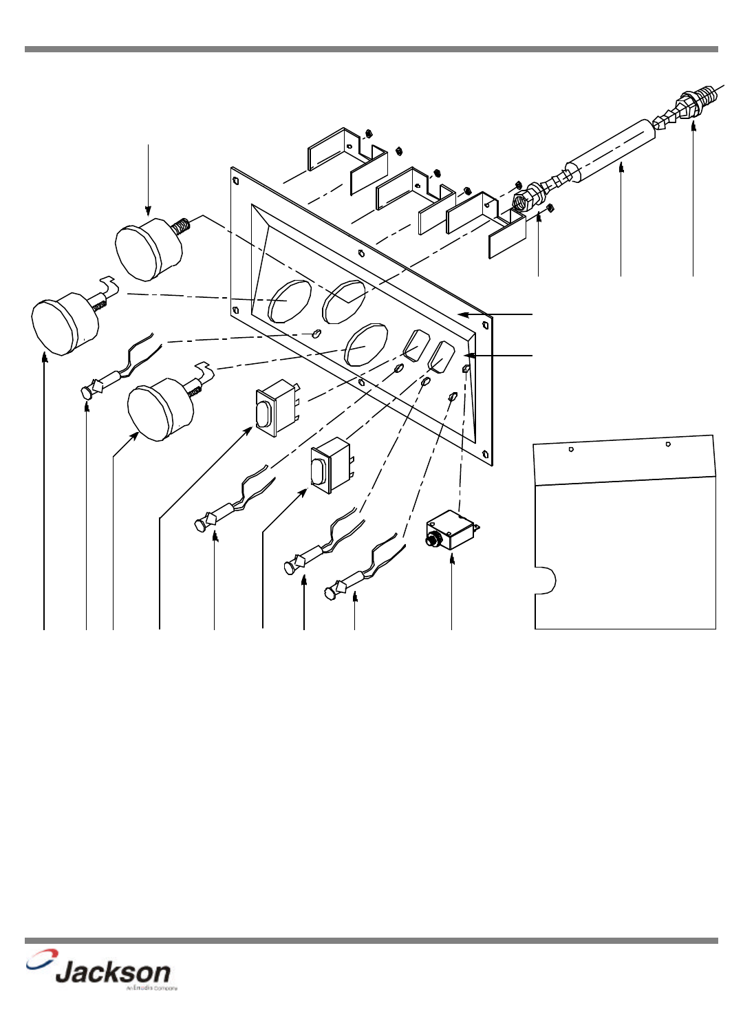
SECTION 6: PARTS SECTION
GAUGE PANEL ASSEMBLY
ITEM QTY DESCRIPTION Mfg. No.
11Gauge, 0-100 PSI with Green Zone 06680-011-86-42
21Fitting, 1/4” BARB, 1/4” FNPT Swivel 04730-011-95-42
31Hose, 5/16” x 12" 05700-011-86-45
41Fitting, 1/4” BARB 1/4” MNPT Swivel 04730-011-95-41
51Control Panel 09330-041-85-00
61Decal, Control Panel 09905-031-40-55
71Thermometer, 96” Wash 06685-111-68-49
81Thermometer, 48” Rinse 06685-111-68-48
91Switch, ON/FILL & OFF/DRAIN 05930-301-49-55
10 1 Light, Red 05945111-44-45
11 1Switch, Delime 05930-011-49-00
12 1 Light, Amber 05945111-44-44
13 1 Light, Green 05945111-44-43
14 1 Breaker, 2A Circuit 05925-111-64-18
15 1 Light, Red 05945111-44-45
JP-24BPNSU Technical Manual
7610-002-38-50 Rev. D (11/11/2005)
1
10 119 12
2
5
6
3 4
14138157
Dielectric Cover, Electrical Panel
05700-011-40-48
27
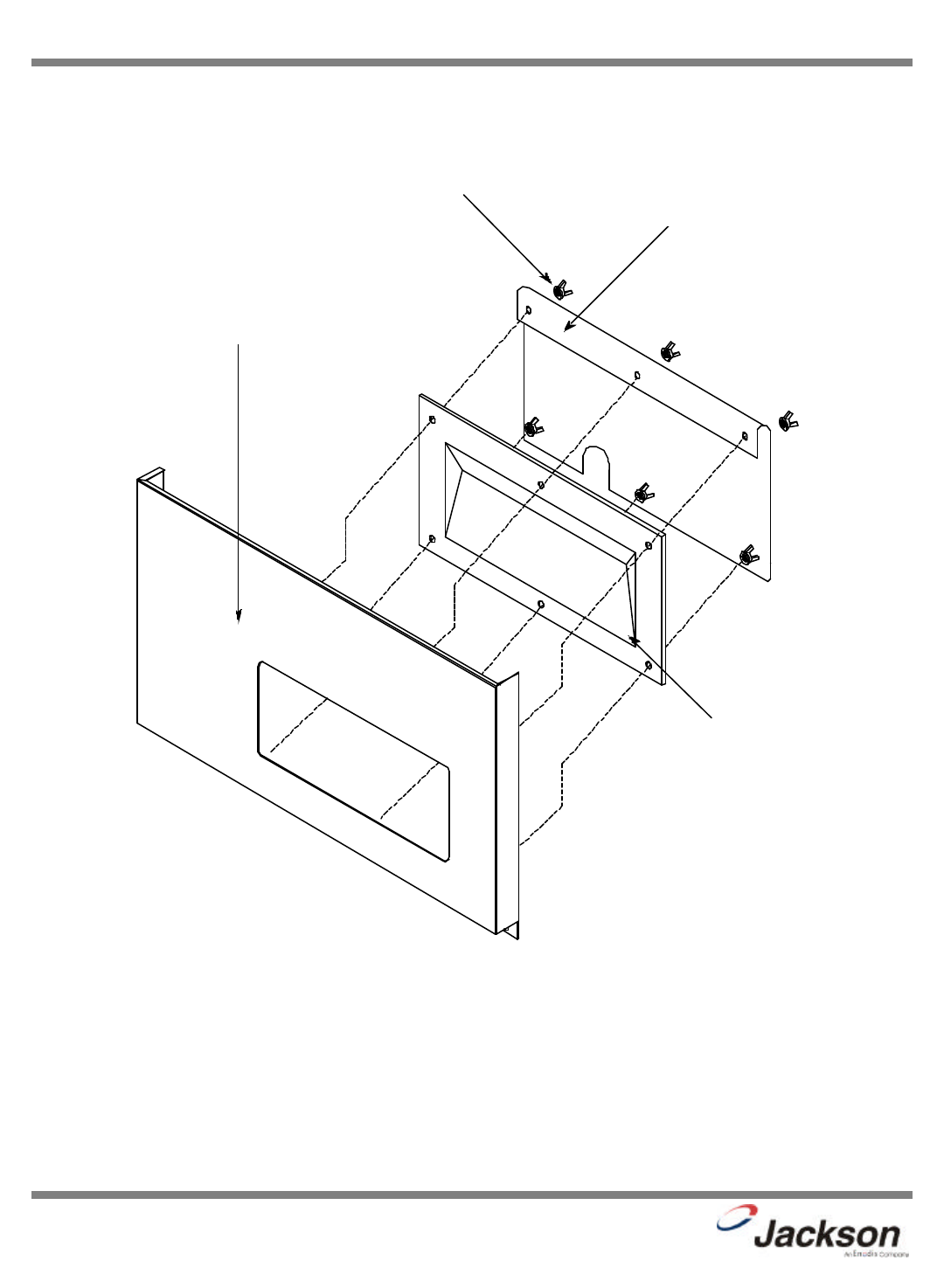
SECTION 6: PARTS SECTION
KICK PLATE ASSEMBLY
JP-24BPNSU Technical Manual
7610-002-38-50 Rev. D (11/11/2005)
Kickplate Weldment
05700-041-86-40
Control Panel Only
09330-041-85-00
Nut, Nylon Wing, 1/4”-20
05310-994-01-00
Dielectric Cover, Kickplate Panel
05700-011-40-49
Decal, Power Disconnect Warning
09905-021-47-07
28
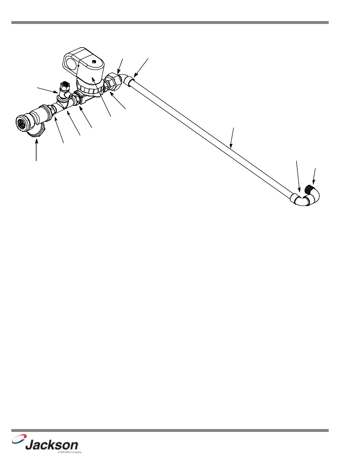
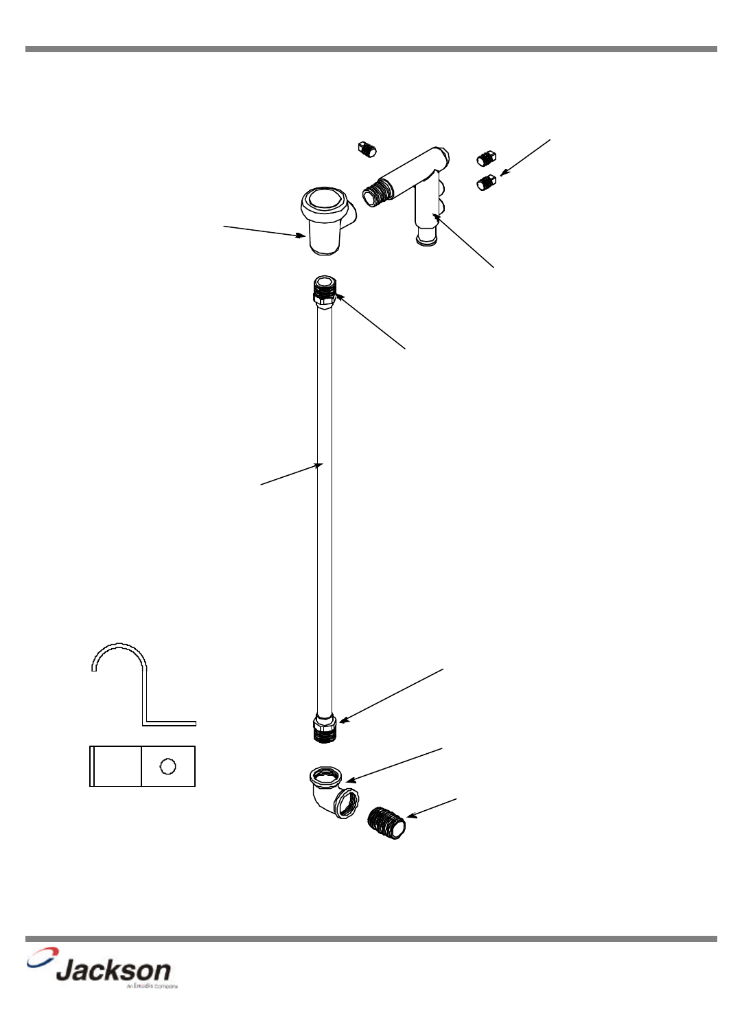
SECTION 6: PARTS SECTION
INCOMING PLUMBING ASSEMBLY
ITEM QTY DESCRIPTION Mfg. No.
11Y-Strainer, 1/2" 04730-217-01-10
23Adapter, 1/2" Ftg x Male 04730-011-59-53
31Tee, 1/2” x 1/2” x 1/4” 04730-411-25-01
41Ball Valve, Test Cock 1/4" 04810-011-72-67
51Valve, Solenoid 1/2" 110 volt 04810-100-12-18
61Union, 1/2" C to C 04730-412-05-01
72Elbow, 1/2" C to Ftg 04730-406-31-01
81Copper Tube, 1/2" x 18 1/2" 05700-011-44-34
91Elbow, 1/2", 90 Deg. C to MSPS 04730-406-32-01
JP-24BPNSU Technical Manual
7610-002-38-50 Rev. D (11/11/2005)
1
7
2
6
3
2
5
2
4
8
7
9
29
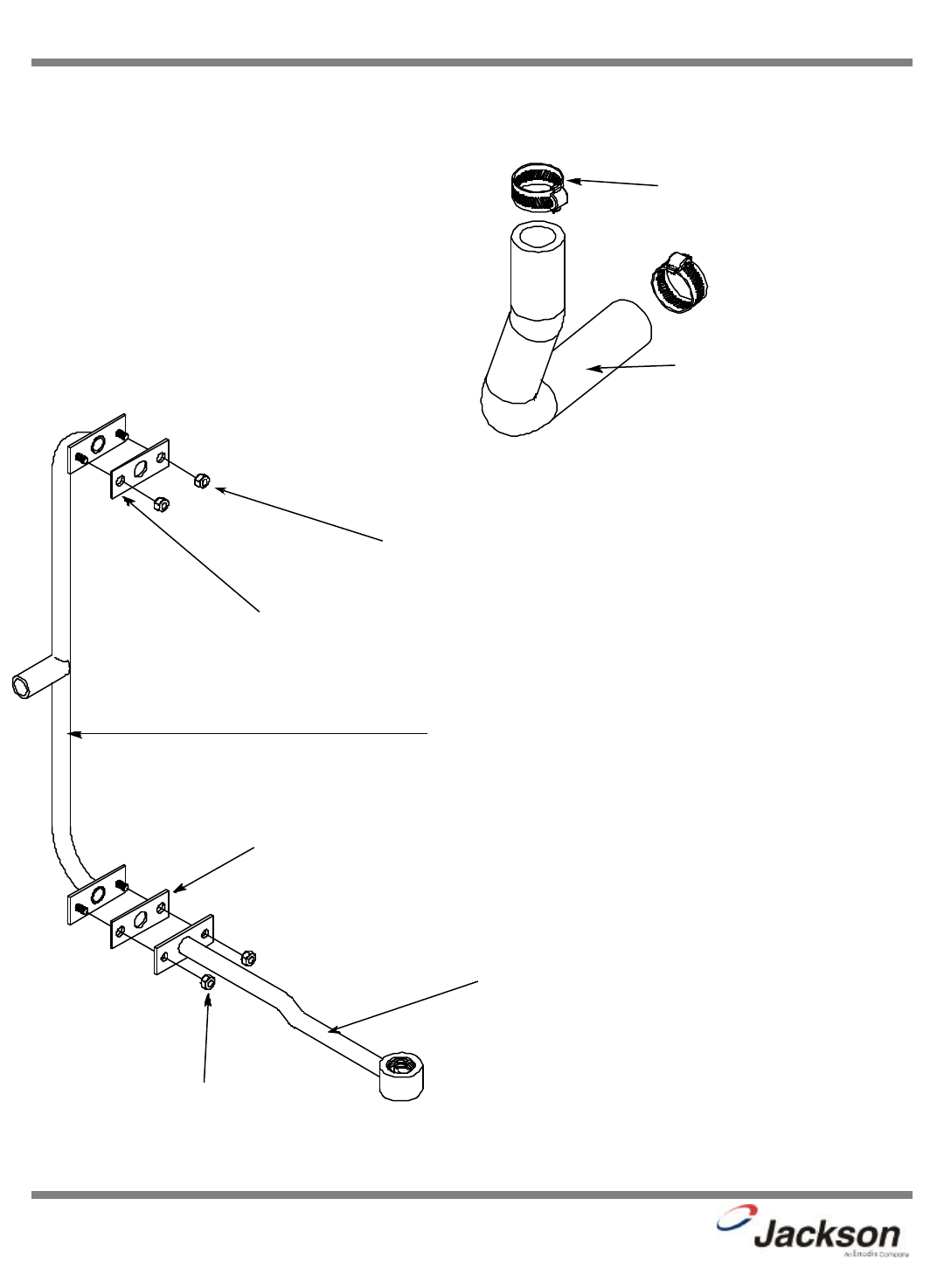
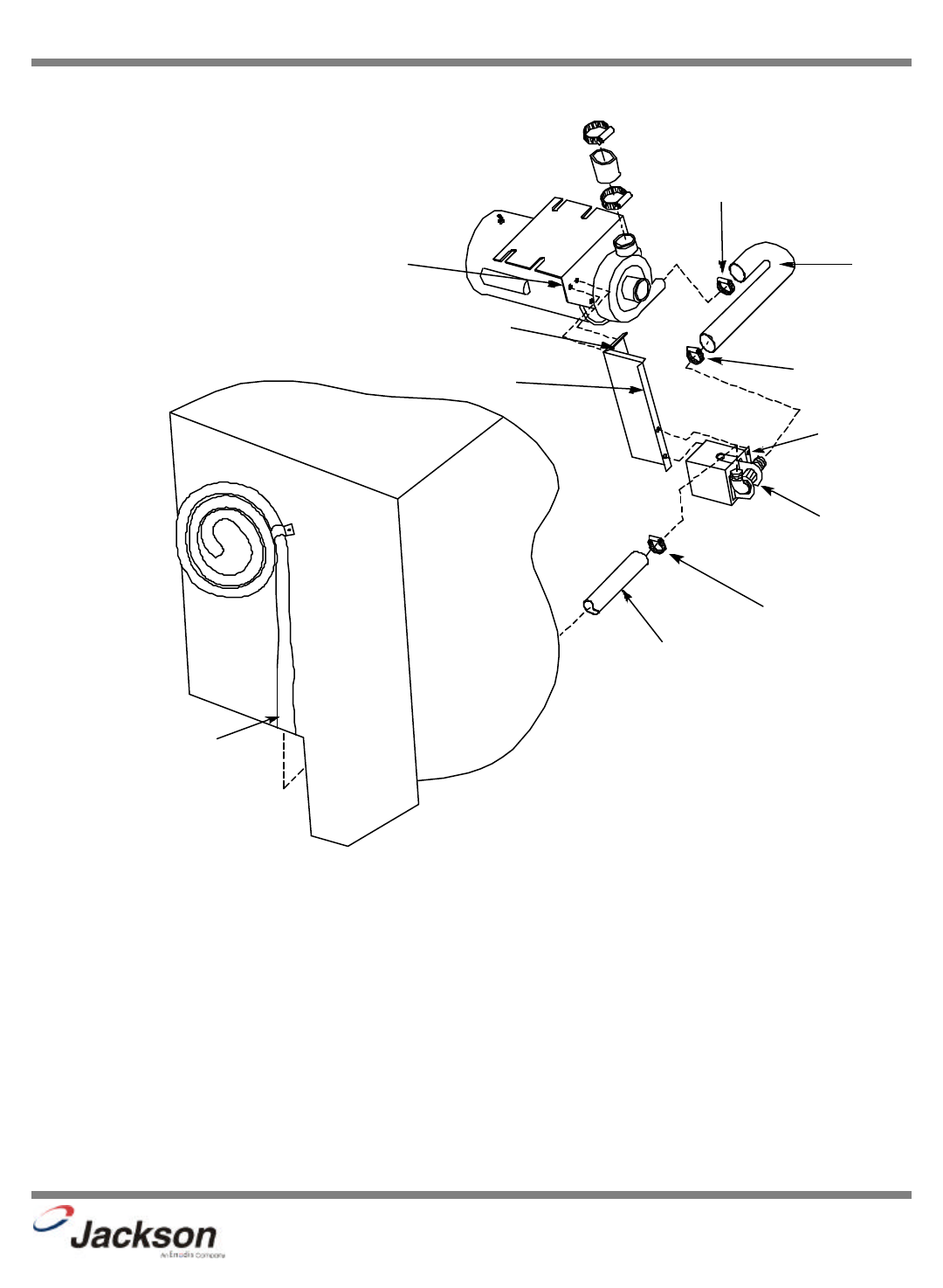
SECTION 6: PARTS SECTION
PLUMBING ASSEMBLY (CONTINUED)
JP-24BPNSU Technical Manual
7610-002-38-50 Rev. D (11/11/2005)
Vacuum Breaker
04820-003-06-13
Adapter, 1/2" Ftg. x Male
04730-401-03-01
Plug, 1/4” Brass
3 per machine
04730-209-01-00
Injector Weldment
05700-031-41-83
Adapter, 1/2" Ftg. x Male
04730-401-03-01
Copper Tube, 1/2” x 20 1/4”
05700-031-41-83
Elbow, 1/2” NPT 90BBrass
04730-011-42-96
Nipple, 1/2” Close Brass
04730-207-15-00
Pipe, Clamp
05700-011-38-62
Secure with:
Locknut, 1/4”-20 S/S Hex with Nylon Insert
05310-374-01-00
30
SECTION 6: PARTS SECTION
PLUMBING ASSEMBLY (CONTINUED)
JP-24BPNSU Technical Manual
7610-002-38-50 Rev. D (11/11/2005)
Rinse Stiffener Weldment
05700-002-59-79
Locknut, 1/4”-20 S/S Hex with Nylon Insert
05310-374-01-00
Gasket, Rinse
05330-111-42-81
Gasket, Rinse
05330-111-42-81
Rinse Hub Weldment
05700-021-38-31
Locknut, 1/4”-20 S/S Hex with Nylon Insert
05310-374-01-00
Hose, 3/4” x 8 1/2”
05700-011-38-83
Clamp, Hose
04730-719-06-09
31
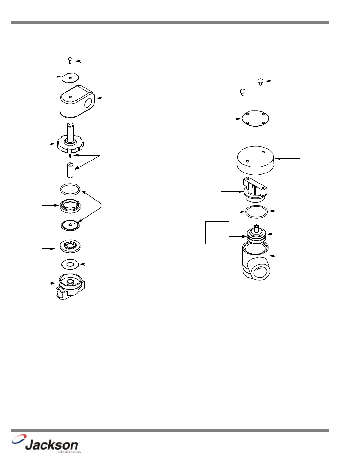
SECTION 6: PARTS SECTION
1/2” SOLENOID VALVE & 1/2” NPT VACUUM BREAKER REPAIR PARTS KITS
JP-24BPNSU Technical Manual
7610-002-38-50 Rev. D (11/11/2005)
Screw
Data Plate
Coil & Housing
06401-003-07-43
Valve Bonnet
Spring & Plunger Kit
06401-003-07-40
Diaphragm
Retainer
Screen
Retainer
Mesh Screen
Valve Body
Complete 110 Volt Solenoid Valve Assembly
04810-100-12-18 Complete Vacuum Breaker Assembly
04820-003-06-13
Components of Repair Kit
06401-003-06-23
Cap Screw
Data Plate
Cap
O-Ring
Plunger
Body
Cap Retainer
Diaphragm & O-ring Kit
06401-003-07-41
32
JP-24BPNSU Technical Manual
7610-002-38-50 Rev. D (11/11/2005)
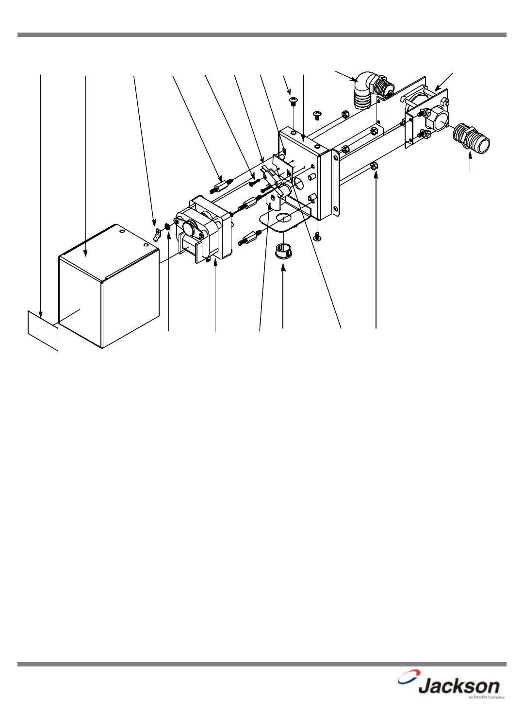
SECTION 6: PARTS SECTION
DRAIN VALVE ASSEMBLY
3
1
3
4
5
6 12 78 9
1011
1813
14
15 16
17
ITEM QTY DESCRIPTION Mfg. No.
1Diverter Valve Assembly, 220 Volt 06401-022-23-21
11Valve, With Brackets 05700-002-23-28
21Hosebarb, 1” x 3/4” NPT Polypropylene 04730-011-65-86
31Hosebarb, 90°1” x 3/4” NPT 04730-011-65-87
41Plate, Motor Mounting Weldment 05700-031-96-02
54Tricnut, 10-32 AK Fastener, S/S 05340-111-58-10
61Lockwasher, #10 External Tooth 05311-273-02-00
71Grommet, Heyco 05975210-03-00
81Cam Weldment 05700-011-65-78
91Plate, Dielectric 05700-011-65-80
10 1 Switch, Micro 05930-011-65-81
11 2Screw, 4-40 x 5/8" 05305-011-49-70
12 1 Motor, Chemical Feeder Pump 14 RPM 220 Volt 04320-011-79-34
13 1 Terminal, Ground Spade 05940-011-75-70
14 4 Locknut, 10-32 S/S Hex with Nylon Insert 05310-373-02-00
15 1 FW-Valve, Cover 05700-031-65-70
16 4 Screw, 10-32 x 3/8” Truss Head 05305-173-12-00
17 1 Decal, Warning-Disconnect Power 09905-100-75-93
18 4 Screw, Mounting 05305-011-93-30
33
SECTION 6: PARTS SECTION
DRAIN PLUMBING ASSEMBLY
ITEM QTY DESCRIPTION Mfg. No.
11Clamp, 3/16” to 1 1/2” 04730-719-06-09
21Hose, Formed Drain 04720-121-40-36
32Bolt, 10-32 x 1/2 Slotted Truss Head 05305-173-04-00
41Diverter Valve Assembly 06401-022-23-21
51Clamp, 11/16” to 1 1/4” 04730-002-18-40
61Hose, 1” I.D. x 10 Feet Long 05700-011-39-72
72Locknut, 1/4”-20 S/S Hex with Nylon Insert 05310-374-01-00
82Bolt, 1/4”-20 x 1/2” Long 05305-274-02-00
91Bracket, Valve Mounting with Tricnuts 05700-021-66-37
10 2 Washer, #10 External Tooth Star 05311-273-02-00
JP-24BPNSU Technical Manual
7610-002-38-50 Rev. D (11/11/2005)
1
2
5
6
6
7
8
9
4
1
3, 10
34
SECTION 6: PARTS SECTION
WASH MOTOR TO WASH TUB ASSEMBLY
ITEM QTY DESCRIPTION Mfg. No.
11Hub, Discharge Machined 05700-021-37-90
21Gasket, 2” O.D. x 1 1/2” I.D. x 1/16” 05330-200-23-00
31Nut, Jam 1 1/2”-12 NPT 05700-000-86-23
44Hose Clamp, 1 1/16" - 2” 04730-719-18-00
51Hose,1 1/4” x 2 1/4” Reinforced 05700-011-44-48
61Motor, Wash 06105-121-60-06
71Hose, Bottom Manifold Pump 05700-001-22-92
81Gasket, Suction Adapter 05330-021-40-87
91Casting, Suction Adapter 09515-031-39-86
10 4 Washer, S/S 1/4”-20 I.D. 05311-174-01-00
11 6Locknut, 1/4”-20 S/S 05310-374-01-00
12 4 Washer, 1/4” I.D. x 3/4” O.D. S/S 05311-011-76-30
JP-24BPNSU Technical Manual
7610-002-38-50 Rev. D (11/11/2005)
1
2
3
5
4
6
12 4
7
4
8
9
10
11 - NOT SHOWN
11 - NOT SHOWN
35
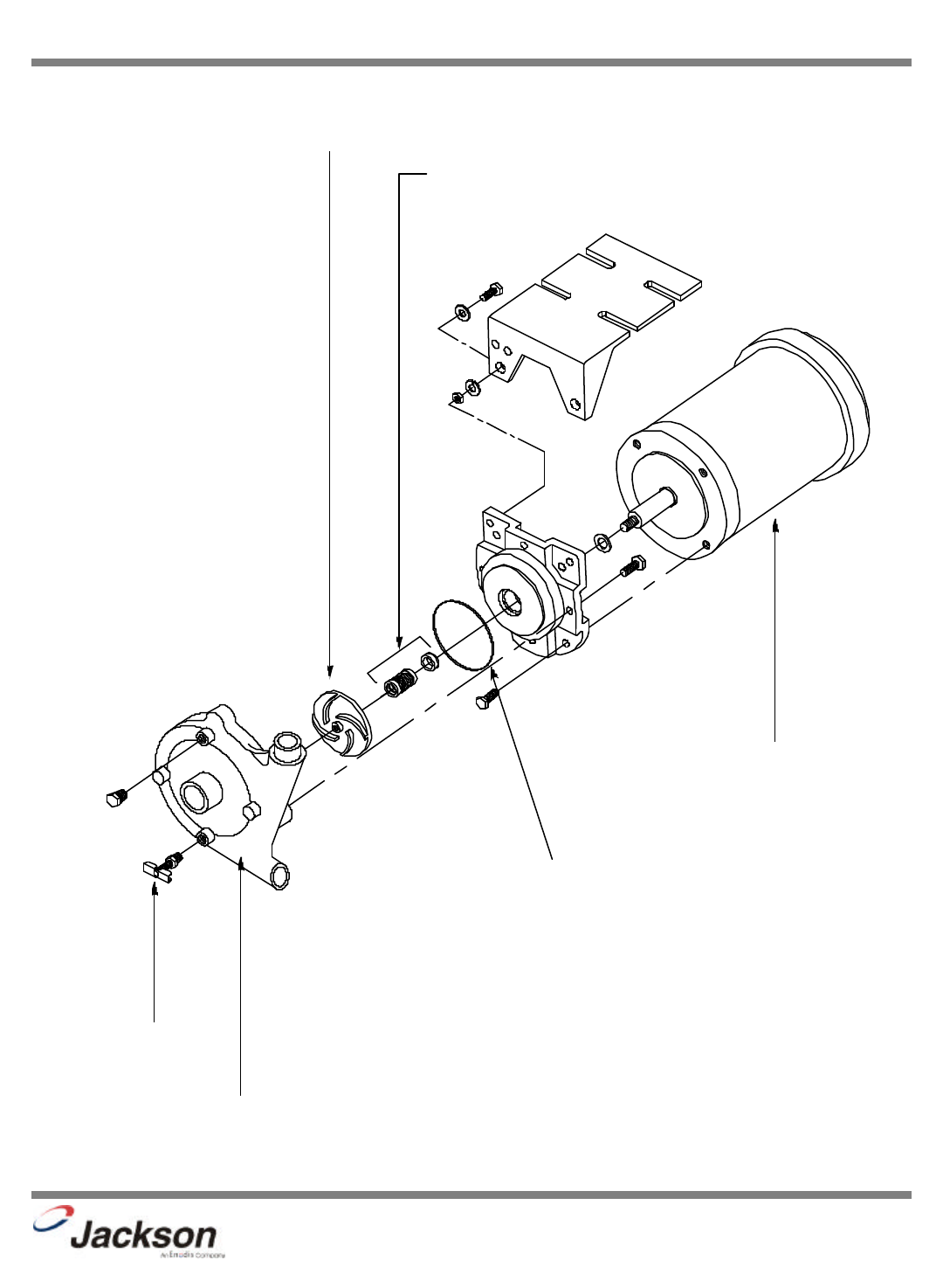
SECTION 6: PARTS SECTION
WASH MOTOR ASSEMBLY
JP-24BPNSU Technical Manual
7610-002-38-50 Rev. D (11/11/2005)
Pump Casing Only
05930-021-44-07
Wash Pump Impeller
04320-021-44-02
Mechanical Seal
05330-011-44-06
Wash Pump Gasket
05330-011-44-08
Test Cock
Motor Only
06105-002-64-03
Complete Assembly
460 Volt, 3/4 Hp
06105-121-60-06
36
JP-24BPNSU Technical Manual
7610-002-38-50 Rev. D (11/11/2005)
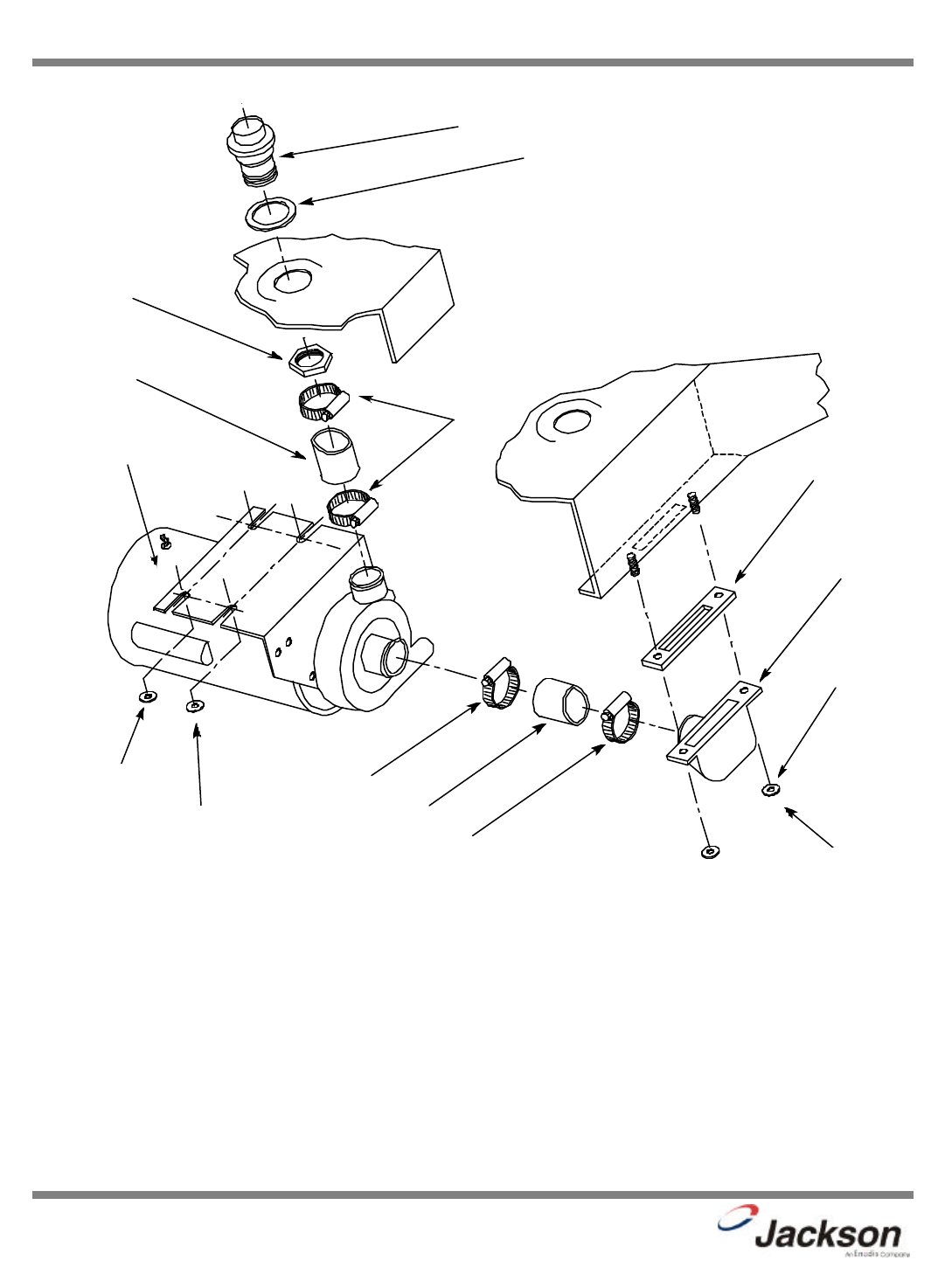
SECTION 6: PARTS SECTION
RINSE TANK & COMPONENTS
40
°F Rise
70
°F Rise
Volts Hz Phase Rinse Heater (8.2 KW) Rinse Heater (10 KW)
460 60 3 04540-111-51-46 04540-002-29-82
Thermostat, High Limit
05930-011-49-43
Decal, High Limit
09905-011-84-32
Thermostat, Rinse Tank
05930-510-03-79
Thermostat Mounting Bracket
05700-011-81-64
The thermostat attaches with 2:
Screw, 6-32 x 3/8” Sems w/External Tooth Washer
05305-002-25-91
Rinse Tank Weldment
05700-031-38-09
Secured with: Locknut, 1/4”-20 S/S Hex with Nylon Insert
05310-374-01-00
Dielectric Cover
05700-011-40-50
Gasket, Heater
05330-011-47-79
Fitting, 1/4” Imperial Brass
05310-924-02-05
Nut, 5/16”-18 S/S Hex
05310-275-01-00
Lockwasher, 5/16” Split
05311-275-01-00
The JP-24BNSU comes supplied with various heaters, depending
on the characteristics of the machine. To ensure that you order the
correct heater for the model you are servicing, please refer to the
following table:
Thermostat Mounting Bracket with Tricnuts
05700-011-65-00
Secured with:
Locknut, 10-24 S/S Hex with Nylon Insert
05310-373-01-00
37
SECTION 6: PARTS SECTION
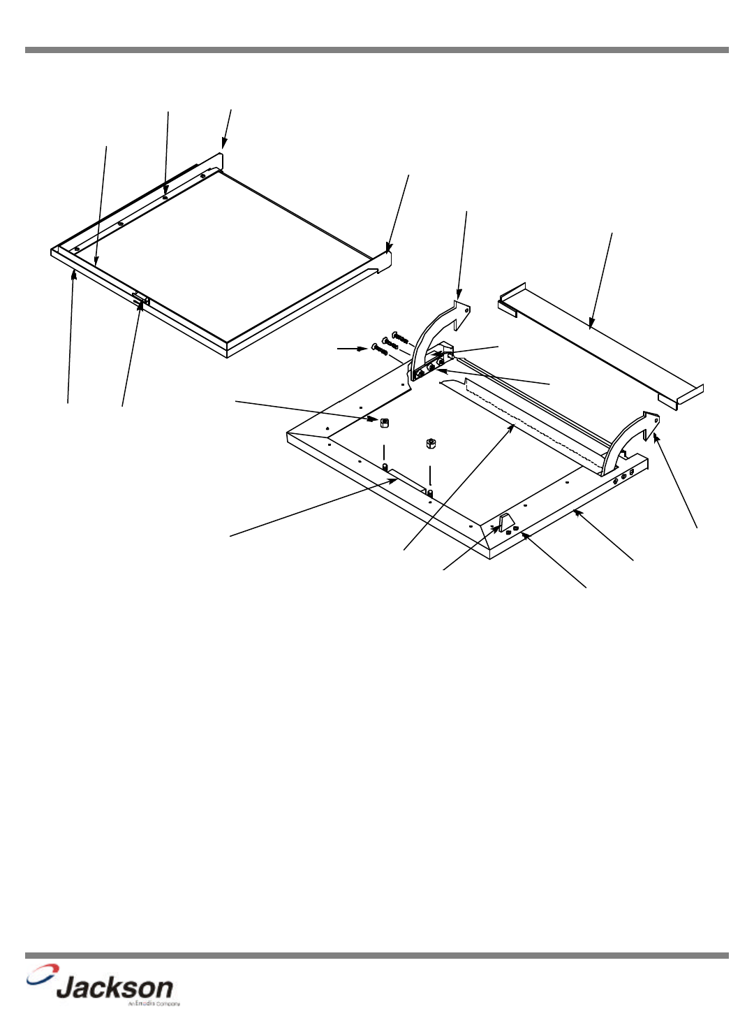
DOOR ASSEMBLY
ITEM QTY DESCRIPTION Mfg. No.
11Door Handle, S/S 05340-011-60-25
21Seal Channel, Inner Door, Left 05700-031-32-89
31Outer Door Weldment 05700-021-35-72
41Right Hinge Assembly Weldment 05700-021-38-75
51Spray Baffle 05700-031-37-56
61Left Hinge Assembly Weldment 05700-021-38-76
72Spacer, Hinge UHMW 05700-011-44-23
86Fastener, Screw, 1/4"-20 x 1-1/2" Long 05305-011-44-50
92Hinge Retaining Plate Assembly 05700-011-44-37
10 1 Baffle, Door 05700-001-44-75
11 1Seal Channel, Inner Door, Right 05700-031-32-91
12 1 Latch Assembly 05700-011-44-41
13 1 Inner Door 05700-031-32-85
14 1 Seal Channel, Inner Door, Top 05700-031-32-90
15 12 Fastener, Screw, 10-32 Counter Sink, 1/2" Long 05305-011-44-51
16 1 Striker, Door Switch 05700-011-44-24
17 2 Fastener, Screw 10-32 x 1/2" Long 05305-011-44-52
18 2 Locknut, 10-32, S/S Hex with Nylon Insert 05310-373-02-00
JP-24BPNSU Technical Manual
7610-002-38-50 Rev. D (11/11/2005)
1
2
3
4
5
6
7
8
9
10
11
12
13
14
15
16 17
18
Order this entire assembly using: 05700-011-39-15
To order the Operation/Instruction Decal
09905-021-41-49
38
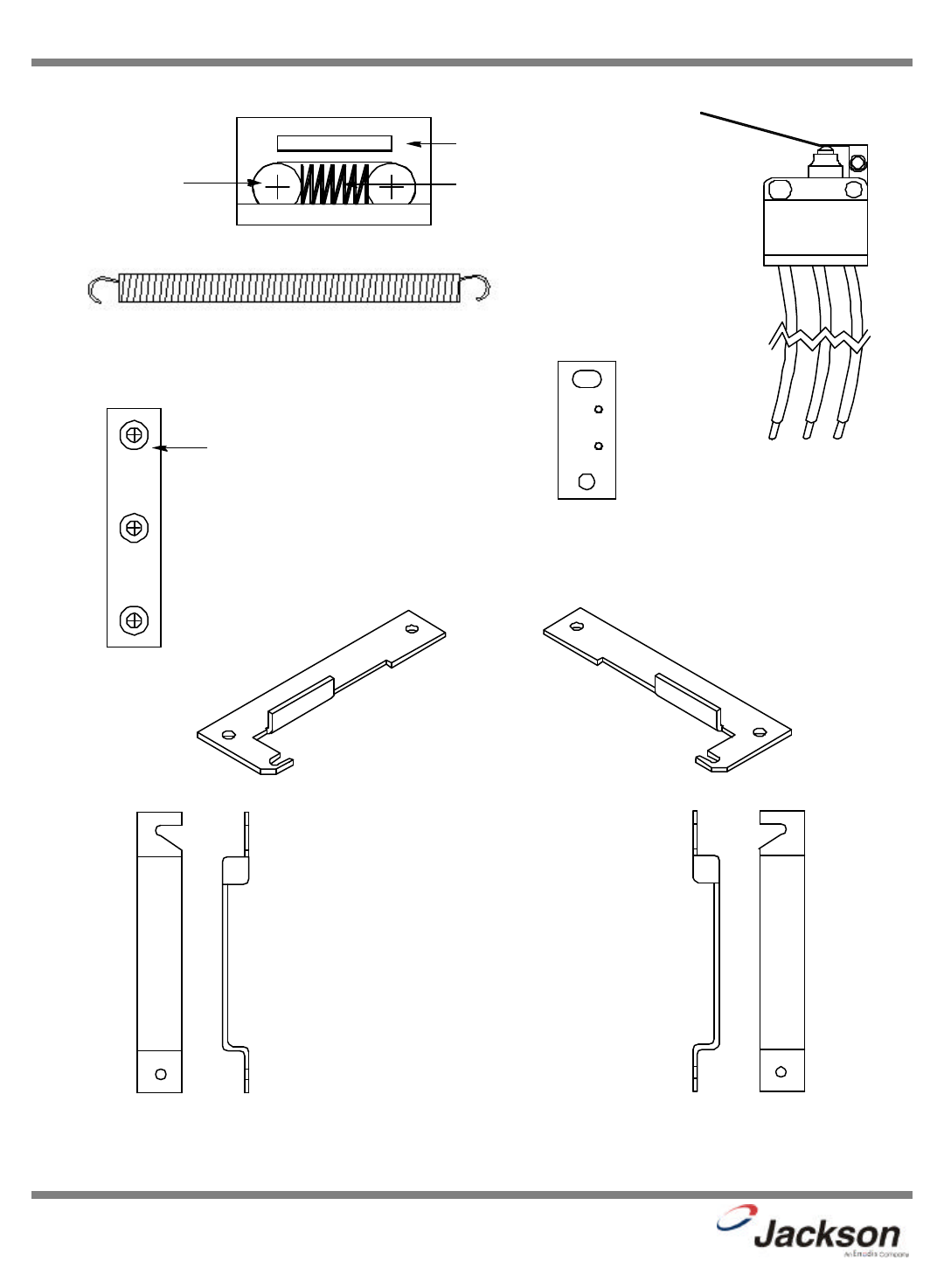
SECTION 6: PARTS SECTION
MISCELLANEOUS DOOR SUB-ASSEMBLIES
JP-24BPNSU Technical Manual
7610-002-38-50 Rev. D (11/11/2005)
Door Spring
05340-011-44-58
Hinge Retaining Plate
05700-011-44-37
Door Latch Casting
05700-011-44-40
Latch Roller
05700-011-44-38 Latch Spring
05700-011-44-39
Door Latch Assembly
05700-011-44-41
Stop, Left Hinge
05700-021-37-67
Cover, Left Hinge Weldment
05700-002-18-41
Stop, Right Hinge
05700-021-37-68
Cover, Right Hinge Weldment
05700-002-18-42
Switch Plate
05700-011-44-22
Door Switch
05930-303-38-00
Hinge Components secured with: Locknut,
1/4”-20 S/S Hex with Nylon Insert
05310-374-01-00
39
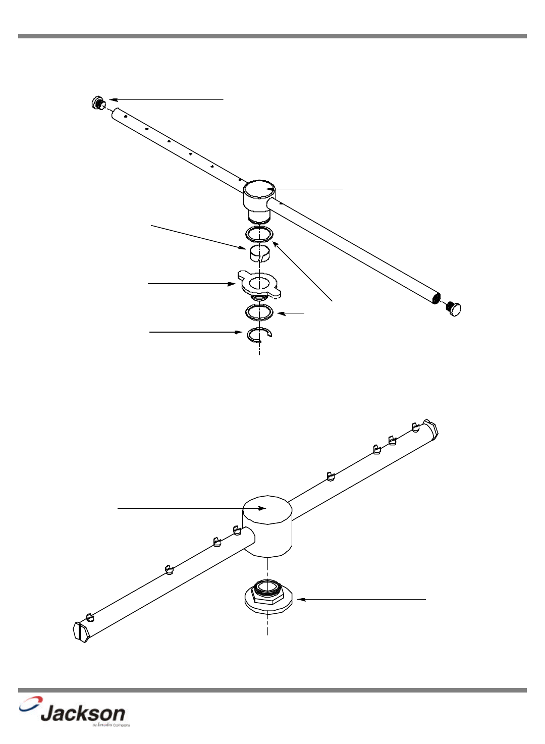
SECTION 6: PARTS SECTION
RINSE ARM & WASH ARM ASSEMBLIES
JP-24BPNSU Technical Manual
7610-002-38-50 Rev. D (11/11/2005)
Washer, Rinse Arm
05330-011-42-10
Rinse Arm
05700-031-38-30
Plug, Rinse Arm
04730-609-04-00
Bushing, Rinse Head
05700-021-33-84
Bearing, Rinse Head
03120-002-72-24
Ring, Retaining
05340-112-01-11
Wash Arm Weldment
05700-021-46-58
Bearing Assembly
05700-021-35-97
O-ring (Not Shown)
05330-002-60-69
Wash Arm Assembly
05700-021-39-23
Rinse Arm Assembly
05700-031-39-21
40
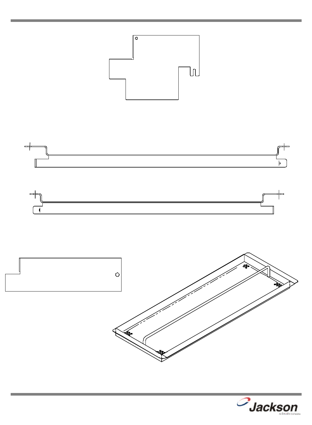
SECTION 6: PARTS SECTION
MISCELLANEOUS PARTS
JP-24BPNSU Technical Manual
7610-002-38-50 Rev. D (11/11/2005)
Guide, Right Rack
05700-031-37-88
Guide, Left Rack
05700-031-37-89
Back Panel
05700-031-44-33
Strainer Spacer
05700-021-35-83
Attaches with:
Nut, Nylon Wing, 1/4”-20
05310-994-01-00 Strainer Weldment
05700-031-35-81
41
SECTION 6: PARTS SECTION
FRAME, SHROUD, & PANEL COMPONENTS
JP-24BPNSU Technical Manual
7610-002-38-50 Rev. D (11/11/2005)
Left Frame Weldment
05700-011-73-85 Right Frame Weldment
05700-011-73-86
The swivel feet used on the unit may be ordered using 05340-108-02-00
Shroud Weldment
05700-031-38-15
Secured with 10-32 x 1/2” Long Screws
05305-173-04-00
Right Dress Panel
05700-041-38-08
Left Dress Panel
05700-041-38-37
Top Panel
05700-041-38-38
The Panels are secured with 10-32 x 1/2” Truss Head Screws, 05305-011-39-36

SECTION 7:
ELECTRICAL DIAGRAMS
42
43
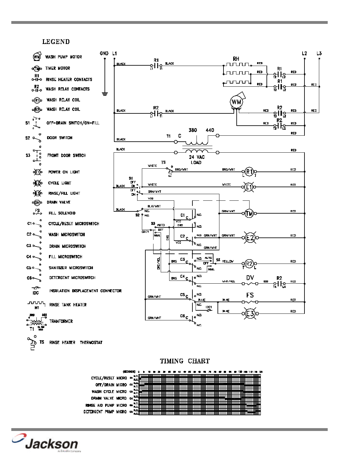
SECTION 7: ELECTRICAL DIAGRAMS
JP-24BPNSU (460 VOLT, 60 HERTZ, THREE PHASE)
JP-24BPNSU Technical Manual
7610-002-38-50 Rev. D (11/11/2005)
9905-031-51-11
Ref: NAVSEAINST 4160.3A
(Insert Classification of TMDER Here) CLASSIFICATION
:
NAVSEA S0005-AA-GYD-030/TMMP
NAVSEA/SPAWAR TECHNICAL MANUAL DEFICIENCY/EVALUATION REPORT (TMDER)
INSTRUCTION: Continue on 8 1/2" x 11" paper if additional space is needed.
1. USE THIS REPORT TO INDICATE DEFICIENCIES, PROBLEMS, AND RECOMMENDATIONS RELATING TO PUBLICATION.
2.
FOR CLASSIFIED TMDERS. SEE OPNAVINST 5510H FOR MAILING CLASSIFIED TMDERS.
3.
Submit TMDERS at web site
http://nsdsa.nswses.navy.mil
or mail
1.
PUB NO.
2.
VOL/PART
3.
REV. NO./DATE OR TM
CH. NO./DATE
4.
SYSTEM/EQUIPMENT IDENTIFICATION
5.
TITLE
6.
REPORT CONTROL NUMBER (UIC-YEAR-XXXX)
7.
RECOMMENDED CHANGES TO PUBLICATION
PAGE
NO.
A.
PARA-
GRAPH
B.
C.
RECOMMENDED CHANGES AND REASONS
8.
ORIGINATOR'S NAME AND WORK
CENTER (Please Print)
9.
DATE
10.
DSN/COMM NO.
11.
TRANSMITTED TO; (NSDSA WILL FILL IN)
12.
SHIP HULL NO. AND/OR STATION ADDRESS (Do Not Abbreviate)
13.
ORIGINATORS EMAIL ADDRESS
NAVSEA 4160/1 (REV 2-99
) SN 0116-LF-019-5300 (Destroy Old Stock)
44

45
FOLD HERE
FOLD HERE
DEPARTMENT OF THE NAVY PLACE
POSTAGE
HERE
COMMANDER
NSDSA CODE 5E30
NAVSURFWARCENDIV
4363 MISSILE WAY
PORT HUENEME CA 93043-4307
Ref: NAVSEAINST 4160.3A
(Insert Classification of TMDER Here) CLASSIFICATION
:
NAVSEA S0005-AA-GYD-030/TMMP
NAVSEA/SPAWAR TECHNICAL MANUAL DEFICIENCY/EVALUATION REPORT (TMDER)
INSTRUCTION: Continue on 8 1/2" x 11" paper if additional space is needed.
1. USE THIS REPORT TO INDICATE DEFICIENCIES, PROBLEMS, AND RECOMMENDATIONS RELATING TO PUBLICATION.
2.
FOR CLASSIFIED TMDERS. SEE OPNAVINST 5510H FOR MAILING CLASSIFIED TMDERS.
3.
Submit TMDERS at web site
http://nsdsa.nswses.navy.mil
or mail
1.
PUB NO.
2.
VOL/PART
3.
REV. NO./DATE OR TM
CH. NO./DATE
4.
SYSTEM/EQUIPMENT IDENTIFICATION
5.
TITLE
6.
REPORT CONTROL NUMBER (UIC-YEAR-XXXX)
7.
RECOMMENDED CHANGES TO PUBLICATION
PAGE
NO.
A.
PARA-
GRAPH
B.
C.
RECOMMENDED CHANGES AND REASONS
8.
ORIGINATOR'S NAME AND WORK
CENTER (Please Print)
9.
DATE
10.
DSN/COMM NO.
11.
TRANSMITTED TO; (NSDSA WILL FILL IN)
12.
SHIP HULL NO. AND/OR STATION ADDRESS (Do Not Abbreviate)
13.
ORIGINATORS EMAIL ADDRESS
NAVSEA 4160/1 (REV 2-99
) SN 0116-LF-019-5300 (Destroy Old Stock)
46

47
FOLD HERE
FOLD HERE
DEPARTMENT OF THE NAVY PLACE
POSTAGE
HERE
COMMANDER
NSDSA CODE 5E30
NAVSURFWARCENDIV
4363 MISSILE WAY
PORT HUENEME CA 93043-4307

SECTION 8: JACKSON MAINTENANCE &
REPAIR CENTERS
48

49
JP-24BPNSU Technical Manual
7610-002-38-50 Rev. D (11/11/2005)
SECTION 8: JACKSON MAINTENANCE & REPAIR CENTERS
ALABAMA TO FLORIDA
ALABAMA:
JONES-McLEOD
APPLIANCE SVC
1616 7TH AVE. NORTH
BIRMINGHAM, AL 35203
(205) 251-0159
800-821-1150
FAX: (205) 322-1440
service@jones-mcleod.com
JONES-McLEOD
APPLIANCE SVC
854 LAKESIDE DRIVE
MOBILE, AL 36693
(251) 666-7278
800-237-9859
FAX: (251) 661-0223
ALASKA:
RESTAURANT
APPLIANCE SVC
7219 ROOSEVELT WAY NE
SEATTLE, WA 98115
(206) 524-8200
800-433-9390
FAX: (206) 525-2890
info@restappl.com
ARIZONA:
AUTHORIZED COMMERCIAL
FOOD EQMT. SVC
4832 SOUTH 35TH STREET
PHOENIX, AZ 85040
(602) 234-2443
800-824-8875
FAX: (602) 232-5862
acsboss@aol.com
GCS SERVICE INC.
PHOENIX, AZ
800-510-3497
ARKANSAS:
BROMLEY PARTS & SVC
10TH AND RINGO
P.O. BOX 1688
LITTLE ROCK, AR 72202
(501) 374-0281
800-482-9269
FAX: (501) 374-8352
service@bromleyparts.com
parts@bromleyparts.com
COMMERCIAL PARTS & SVC.
3717 CHERRY ROAD
MEMPHIS, TN 38118
(901) 366-4587
800-262-9155
FAX: (901) 366-4588
CALIFORNIA:
BARKERS FOOD
MACHINERY SERVICES
5367 SECOND STREET
IRWINDALE, CA 91706
(626) 960-9390
800-258-6999
FAX: (626) 337-4541
service@barkers.com
GCS SERVICE INC.
LOS ANGELES, CA
800-327-1433
P & D APPLIANCE
4220-C ROSEVILLE ROAD
NORTH HIGHLANDS, CA 95660
(916) 974-2772
800-824-7219
FAX:(916) 974-2774
INDUSTRIAL ELECTRIC SVC
5662 ENGINEER DRIVE
HUNTINGON BEACH, CA 92649
(714) 379-7100
800-457-3783
FAX: (714) 379-7109
GCS SERVICE INC.
1196 CHERRY LANE
SAN BRUNO, CA 92121
(858) 549-8411
800-422-7278
BARKERS FOOD
MACHINERY SERVICES
9373 ACTIVITY ROAD #G
SAN DIEGO, CA 92126
(858) 695-1091
800-995-7955
FAX: (858) 695-0092
GCS SERVICE INC.
9030 KENAMAR DR. SUITE 313
SAN DIEGO, CA 92121
(858) 549-8411
800-422-7278
FAX: (858) 549-2323
P & D APPLIANCE SVC
100 SOUTH LINDEN AVE.
S. SAN FRANCISCO, CA 94080
(650) 635-1900
800-424-1414
FAX: (650) 635-1919
pndappl@aol.com
GCS SERVICE INC.
650 S. GRAND AVE #111
SANTA ANA, CA 92705
(714) 541-8496
800-327-1433
COLORADO:
HAWKINS COMMERCIAL
APPLIANCE SERVICE
56 BUCHANAN
COLORADO SPRINGS, CO
80110
(719) 477-1242
FAX: (719) 477-1513
HAWKINS COMMERCIAL
APPLIANCE SERVICE
3000 S. WYANDOT ST.
ENGLEWOOD, CO 80110
(303) 781-5548
(800) 624-2117
FAX: (303) 761-8861
METRO APPLIANCE SERVICE
1640 S BROADWAY
DENVER, CO 80210
(303) 778-1126
800-525-3532
FAX: (303) 778-0268
metroappls@aol.com
GCS SERVICE INC.
DENVER, CO
800-510-3497
CONNECTICUT:
GCS SERVICE INC.
302 MURPHY ROAD
HARTFORD, CT 06114
(860) 549-5575
800-423-1562
FAX: (860) 527-6355
DELAWARE:
AMERICAN KITCHEN MACHIN-
ERY & REPAIR
204 QUARRY STREET
PHILADELPHIA, PA 19106
(215) 627-7760
800-848-7760
FAX: (215) 627-1604
ELMER SCHULTZ SERVICE
36 BELMONT AVE.
WILLMINGTON, DE 19804
(302) 655-8900
800-225-0599
FAX: (302) 656-3673
elmer2@erols.com
GCS SERVICE INC.
PHILADELPHIA, PA
800-441-9115
EMR SERVICE DIVISION
106 WILLIAMSPORT CIRCLE
SALISBURY, MD 21804
(410) 543-8197
FAX: (410) 548-4038
DELAWARE (cont.):
GCS SERVICE INC.
ELMWOOD CIRCLE 1
SAHRON HILL, PA 19079
(215)925-6217
800-441-9115
FAX: (215) 925-6208
FLORIDA:
COMMERCIAL APPLIANCE SVC
8416 LAUREL FAIR CIRCLE
BLDG 6, SUITE 114
TAMPA, FL 33610
(813) 663-0313
800-282-4718
FAX: (813) 663-0212
commercialappliance@worldnet.at
t.net
COMMERCIAL APPLIANCE SVC
5791 YOUGQUIST RD. #1
FT. MEYERS, FL 33912
(941) 466-5883
800-671-1837
FAX: (941) 466-1454
COMMERCIAL APPLIANCE SVC
6270 EDGEWATER DR. #3400
ORLANDO, FL 32810
(407) 532-2107
FAX: (407) 532-2640
COMMERCIAL APPLIANCE SVC
6653 POWERS AVE. SUITE 241
JACKSONVILLE, FL 32217
(904) 626-6684
800-282-4718
FAX: (904) 636-6685
GCS SERVICE INC
3373 N. W. 168TH STREET
MIAMI, FL 33056
(305) 621-6666
800-766-8966
FAX: (305) 621-6656
GCS SERVICE INC
3902 CORPOREX PARK DR.
SUITE 350
TAMPA, FL 33619
(813) 626-6044
800-282-3008
FAX: (813) 621-1174
JONES-McLEOD
APPLIANCE SVC
854 LAKESIDE DRIVE
MOBILE, AL 36693
(334) 666-7278
800-237-9859
FAX: (334) 661-0223
service@jones-mcleod.com

50
JP-24BPNSU Technical Manual
7610-002-38-50 Rev. D (11/11/2005)
SECTION 8: JACKSON MAINTENANCE & REPAIR CENTERS
GEORGIA TO MARYLAND
GEORGIA:
GCS SERVICE INC
3127 PRESIDENTIAL DRIVE
ATLANTA, GA 30340
(770) 452-7322
800-334-3599
FAX: (770) 452-7473
HERITAGE SERVICE GROUP
2100 NORCROSS PKWY.
SUITE 130
NORCROSS, GA 30071
(770) 368-1465
800-388-9837
FAX: (866) 388-9837
WHALEY FOODSERVICE
REPAIRS
2909 LANDFORD RD. B-200
NORCROSS, GA 31405
(678) 243-7973
FAX: (678) 243-7974
WHALEY FOODSERVICE
REPAIRS
109-A OWENS INDUSTRIAL
DRIVE
SAVANNAH, GA 31405
(912) 447-0827
888-765-0036
FAX: (912) 447-0826
HAWAII:
FOOD EQMT. PARTS & SER-
VICE CO.
300 PUUHALE RD.
HONOLULU, HI 96819
(808) 847-4871
FAX: (808) 842-1560
fepsco@hula.net
IDAHO:
RON'S SERVICE
703 E 44TH STREET STE 10
GARDEN CITY, ID 83714
(208) 375-4073
FAX: (208) 375-4402
RESTAURANT APPLIANCE SVC.
7219 ROOSEVELT WAY NE
SEATTLE, WA 98115
(206) 524-8200
800-433-9390
FAX: (206) 525-2890
info@restappl.com
ILLINOIS:
EICHENAUER SERVICES INC.
106 E. MCCLURE
PEORIA, IL 61603
(309) 682-9390
FAX: (309) 682-3728\
ILLINOIS (cont.):
GENERAL PARTS INC.
248 JAMES ST.
BENSONVILLE, IL 60106
(630) 595-3300
800-880-3604
FAX: (630) 595-0006
CONES REPAIR SVC.
2408 40TH AVE.
MOLINE, IL 61265
(309) 797-5323
800-716-7070
FAX: (309)797-3631
jackb@cones.com
EICHENAUER SERVICES INC.
130 S OAKLAND ST.
DECATUR, IL 62522
(217) 429-4229
800-252-5892
FAX: (217) 429-0226
esi@esiquality.com
EICHENAUER SERVICES INC.
405-B S. NEIL ST.
CHAMPAGNE, IL 61820
(217) 359-4200
FAX: (217) 398-2960
GCS SERVICE INC.
696 LARCH AVENUE
ELMHURST, IL 60126
(630) 941-7800
800-942-9689
FAX: (630) 941-6048
GCS SERVICE INC.
9722 REAVIS PARK DRIVE
ST. LOUIS, MO 63123
(314) 638-7444
800-284-4427
FAX: (314) 638-0135
INDIANA:
GCS SERVICE INC.
5310 E. 25TH STREET
INDIANAPOLIS, IN 46218
(317) 545-9655
800-727-8710
FAX: (317) 549-6286
GENERAL PARTS INC.
622 LA PAS TRAIL
INDIANAPOLIS, IN 46268
(317) 290-8060
800-410-9794
FAX: (317) 290-8085
IOWA:
GOODWIN-TUCKER GROUP
3509 DELAWARE AVENUE
DES MOINES, IA 50313
(515) 262-9308
800-372-6066
FAX: (515) 262-2936
goodwintuc@aol.com
GOODWIN-TUCKER GROUP
958 W. PARKER ST.
WATERLOO, IA 50703
(319) 232-5049
800-554-5049
FAX: (319) 232-2247
GOODWIN-TUCKER GROUP
935 33RD AVE SW
CEDAR RAPIDS, IA 50204
(619) 365-1311
866-365-1552
FAX: (866) 365-1551
CONES REPAIR SVC.
1056 27TH AVENUE SW
CEDAR RAPIDS, IA 52404
(319) 365-3325
800-747-3326
FAX: (319) 365-0885
KANSAS:
GCS SERVICE INC.
6107 CONNECTICUT
KANSAS CITY, MO 64210
(816) 920-5999
800-229-6477
FAX: (816) 920-7387
GENERAL PARTS INC.
1101 E. 13TH STREET
KANSAS CITY, MO 64106
(816) 421-5400
800-279-9967
FAX: (816) 421-1270
KENTUCKY:
CERTIFIED SERVICE CENTER
1051 GOODWIN DRIVE
LEXINGTON, KY 40505
(606) 254-8854
800-432-9269
FAX: (606) 231-7781
jatkins@certifiedsc.com
CERTIFIED SERVICE CENTER
4283 PRODUCE ROAD
LOUISVILLE, KY 40218
(502) 964-7007
800-637-6350
FAX: (502) 964-7202
cwalker@certifiedsc.com
droenigk@certifiedsc.com
KENTUCKY (cont.):
CERTIFIED SERVICE CENTER
127 DISHMAN LANE
BOWLING GREEN, KY 42101
(270) 783-0012
FAX: (270) 783-0058
GCS SERVICE CENTER
4600 SHEPHERDSVILLE, RD
LOUISVILLE, KY 40218
(502) 367-1788
800-752-6160
FAX: (502) 367-0400
GCS SERVICE CENTER
533 CODELL DR. UNIT A
LEXINGTON, KY 40509
(859) 269-7484
800-432-9260
GCS SERVICE CENTER
127 DISHMAN LANE
BOWLING GREEN, KY 42101
(270) 783-0012
800-783-0058
LOUISIANA:
BANA PARTS INC.
1501 KUEBLE STREET
HARAHAN, LA 70123
(504) 734-0076
800-325-7543
FAX: (504) 734-8456
MAINE:
MRE, INC.
170 JOHN ROBERTS RD UNIT #3
PROTLAND, ME 04106
(207) 772-1152
800-823-9700
FAX: (207) 772-1445
MARYLAND:
EMR SERVICE DIVISION
700 EAST 25TH STREET
BALTIMORE, MD 21218
(410) 467-8080
800-879-4994
FAX: (410) 467-4191
baltparts@emrco.com
EMR SERVICE DIVISION
106 WILLIAMSPORT CIRCLE
SALISBURY, MD 21804
(410) 543-8197
888-687-8080
FAX: (410) 548-4038
baltparts@emrco.com

51
JP-24BPNSU Technical Manual
7610-002-38-50 Rev. D (11/11/2005)
SECTION 8: JACKSON MAINTENANCE & REPAIR CENTERS
MARYLAND TO NEW YORK
MARYLAND (cont.):
EMR SERVICE DIVISION
2626 PITTMAN DRIVE
SILVER SPRING, MD 20910
(301) 588-8080
800-348-2365
FAX: (301) 588-6985
baltparts@emrco.com
GCS SERVICE INC.
2660 PITTMAN DRIVE
SILVER SPRING, MD 20910
(301) 585-7550 (DC)
(410) 792-0338 (BALT)
(800) 638-7278
FAX: (301) 495-4410
MASSACHUSETTS:
ACE SERVICE CO.
95 HAMPTON AVE.
NEEDHAM, MA 02494
(781) 449-4220
800-225-4510 MA & NH
FAX: (781) 444-4789
taceservice@aol.com
MASSACHUSETTS
RESTAURANT SUPPLY
34 SOUTH STREET
SOMERVILLE, MA 02143
(617) 868-1930
800-338-6737
FAX: (617) 868-5331
GCS SERVICE INC.
180 SECOND STREET
CHELSEA, MA 02150
(617) 889-9393
800-225-1155
FAX: (617) 889-1222
GCS SERVICE INC.
302 MURPHY ROAD
HARTFORD, CT 06114
(860) 549-5575
800-723-1562
FAX: (860) 527-6355
MICHIGAN:
GCS SERVICE INC.
31829 WEST EIGHT MILE ROAD
LIVONIA, MI 48152
(248) 426-9500
800-772-2936
FAX: (248) 426-7555
JACKSON SERVICE
COMPANY
3980 BENSTEIN RD.
COMMERCE TOWNSHIP, MI
48382
(248) 363-4159
800-332-4053
FAX: (248) 363-5448
MINNESOTA:
GENERAL PARTS INC.
11311 HAMPSHIRE AVE. S.
BLOOMING, MN 55438-2456
(612) 944-5800
800-279-9980
FAX: (800) 279-9980
GCS SERVICE INC.
5480 NATHAN LANE SUITE 130
PLYMOUTH, MN 55442
(763) 546-4221
800-345-4221
MISSISSIPPI:
GCS SERVICE INC.
5755 GALLANT DRIVE.
JACKSON, MS 39206
(601) 956-7800
800-274-5954
FAX: (601) 956-1200
GCS SERVICE INC.
108 DISTRIBUTION DR. SUITE A
RICHLAND, MS 39208
(601) 956-7800
877-964-2722
GCS SERVICE INC.
3717 CHERRY ROAD
MEMPHIS, TN 38118
(901) 366-4587
800-262-9155
FAX: (901) 366-4588
MISSOURI:
GCS SERVICE INC.
6107 CONNECTICUT
KANSAS CITY, MO 64120
(816) 920-5999
800-229-6477
FAX: (816) 920-7387
GCS SERVICE INC.
9722 REAVIS PARK DRIVE
ST. LOUIS, MO 63123
(314) 638-7444
800-284-4427
FAX: (314) 638-0135
KAMMERLIN PARTS & SVC.
1539 SOUTH KINGSHIGHWAY
ST. LOUIS, MO 63110
(314) 535-2222
FAX: (314) 535-6205
petek@kps.stl.com
GENERAL PARTS INC.
1101 EAST 13TH ST.
KANSAS CITY, MO 64106
(816) 421-5400
800-279-9967
FAX: (816) 421-1270
MONTANA:
RESTAURANT
APPLIANCE SVC.
7219 ROOSEVELT WAY NE
SEATTLE, WA 98115
(206) 524-8200
800-433-9390
FAX: (206) 525-2890
info@restappl.com
NEBRASKA:
GOODWIN - TUCKER GROUP
7535 D STREET
OMAHA, NE 68124
(402) 397-2880
800-228-0372
FAX: (402) 397-2881
goodwintuc@aol.com
GOODWIN - TUCKER GROUP
4109 PROGRESSIVE AVE
SUITE 1
LINCOLN, NE 68504
(402) 464--8672
888-880-8672
FAX: (402) 464-3070
NEVADA:
HI TECH COMMERCIAL SVC
400 E. MEAD BLVD.
LAS VEGAS, NV 89030
(702) 649-4616
(877) 924-4832
FAX: (702) 649-4607
GCS SERVICE INC.
LAS VEGAS, NV
800-822-2303
NEW HAMPSHIRE:
GCS SERVICE INC.
180 SECOND STREET
CHELSEA, MA 02150
(617)889-9393
800-225-1155
FAX: (617) 889-1222
ACE SERVICE CO.
500 HARVEY RD.
MANCHESTER, NH 03103
(603) 668-5070
800-225-4510
FAX: (603) 626-6067
taceservice@aol.com
MASSACHUSETTS
RESTAURANT SUPPLY
34 SOUTH STREET
SOMERVILLE, MA 02143
(617) 868-1930
800-338-6737
FAX: (617) 868-5331
NEW JERSEY:
JAY HILL REPAIRS
90 CLINTON RD
FAIRFIELD, NJ 07004
(973) 575-9145
800-836-0643
FAX: (973) 575-5890
JACKSON FASPRAY SVC.
155 SARGEANT AVE.
CLIFTON, NJ 07013
(973) 471-8000
800-356-6740
FAX: (973) 471-1289
jfs155@aol.com
AMERICAN KITCHEN
MACHINERY & REPAIR
204 QUARRY STREET
PHILADELPHIA, PA 19106
(215) 627-7760
800-848-7760
FAX: (215) 627-1604
GCS SERVICE INC.
817 N. THIRD STREET
PHILADELPHIA, PA 19123
(215) 925-6217
800-441-9115
FAX: (215) 925-6208
ELMER SCHULTZ SERVICES
201 WASHINGTON AVE.
PLEASANTVILLE, NJ 08232
(609) 641-0317
800-378-1649
FAX:(609) 641-8703
elmer2@erols.com
NEW MEXICO:
STOVE PARTS SUPPLY CO.
2120 SOLANA STREET
FORT WORTH, TX 76117
(817) 831-0381
800-433-1804
FAX: (817) 834-7754
bud@stoveparts.com
HAWKINS COMMERCIAL APPLI-
ANCE SERVICE
300 S. WYANDOT STREET
ENGLEWOOD, CA 80110
(303) 781-5548
800-624-2117
FAX: (303) 761-8861
NEW YORK:
ALL SERVICE KITCHEN
EQUIPMENT REPAIR
10 CHARLES STREET
BROOKLYN, NY 11040
(516) 378-1176
718-528-7777
FAX: (516) 378-1735

52
JP-24BPNSU Technical Manual
7610-002-38-50 Rev. D (11/11/2005)
SECTION 8: JACKSON MAINTENANCE & REPAIR CENTERS
NEW YORK TO PENNSYLVANIA
NEW YORK (cont.):
APPLIANCE INSTALLATION
AND SERVICE CORP.
1336 MAIN STREET
BUFFALO, NY 14209
(716) 884-7425
800-722-1252
FAX: (716) 884-0410
ais@worldnet.att.net
B.E.S.T. INC.
3003 GENESEE STREET
BUFFALO, NY 14225
(716) 893-6464
800-338-5011
FAX: (716) 893-6466
bestserv@aol.com
DUFFY'S EQUIPMENT SVC.
3138 ONEIDA STREET
SAUQUOIT, NY 13456
(315) 737-9401
800-443-8339
FAX: (315) 737-7132
duffyequip@aol.com
NORTHERN PARTS & SVC.
21 NORTHERN AVENUE
PLATTSBURGH, NY 12903
(518) 563-3200
800-634-5005
FAX: (800) 782-5424
info@northernparts.com
ALL ISLAND REPAIR
40-9 BURT DRIVE
DEER PARK, NY 11729
(631) 242-5588
800-323-9411
FAX: (631) 242-6102
A. I. S. COMMERCIAL
PARTS & SVC
1900 COLLEGE AVENUE
ELMIRA HEIGHTS, NY 14901
(607) 734-6072
888-724-7377
FAX: (607) 734-9294
A. I. S. COMMERCIAL
PARTS & SVC
13 WESTR MAIN STREET
FALCONER, NY 14733
(716) 665-6556
800-552-6556
FAX: (716) 665-4227
A. I. S. COMMERCIAL
PARTS & SVC
200 SALINA ST. SUITE 114
LIVERPOOL, NY 13088
(315) 435-0709
800-371-5921
FAX: (315) 453-1412
NEW YORK (cont.):
A. I. S. COMMERCIAL
PARTS & SVC
7387 PITTSFORD VICTOR RD.
ROCHESTER, NY 14610
(716) 461-2370
800-458-4198
FAX: (716) 461-5545
GCS SERVICE INC.
BROOKLYN, NY 11211
800-969-4271
NORTH CAROLINA:
AUTHORIZED APPLIANCE
SERVICE CENTER
1020 TUCKASEEGEE RD.
CHARLOTTE, NC 28208
(704) 377-4501
(800) 532-6127
FAX: (704) 377-4504
WHALEY FOODSERVICE
8334-K ARROWRIDGE BLVD
CHARLOTTE, NC 28273
(704) 529-6242
FAX: (704) 529-1558
info@whaleyfoodservice.com
WHALEY FOODSERVICE
203-D CREEK RIDGE RD.
GREENSBORO, NC 27604
(336) 333-2333
FAX: (336) 333-2533
AUTHORIZED APPLIANCE
SERVICE CENTER
109 HINTON AVE. #4
WILMINGTON, NC 28403
(910) 313-1250
FAX: (910) 313-6130
AUTHORIZED COMMERCIAL
EQUIPMENT SERVICE
800 N. PERSON STREET
RALEIGH, NC 27604
(919) 834-3476
(919) 834-3477
WHALEY FOODSERVICE
REPAIRS
335-105 SHERWEE DRIVE
RALEIGH, NC 27603
(919) 779-2266
FAX: (919) 779-2224
info@whaleyfoodservice.com
WHALEY FOODSERVICE
REPAIRS
6418-101 AMSTERDAM WAY
WILMINGTON, NC 28405
(910) 791-0000
FAX: (910) 791-6662
info@whaleyfoodservice.com
NORTH DAKOTA:
GCS SERVICE INC.
2857 LOUISIANA AVENUE N.
MINNEAPOLIS, MN 55427
(612) 546-4221
800-345-4221
FAX: (612) 546-4286
GENERAL PARTS INC.
10 SOUTH 18TH STREET
FARGO, ND 58103
(701) 235-4161
800-279-9987
FAX: (701) 235-0539
OHIO:
CERTIFIED SERVICE CENTER
890 REDNA TERRACE
CINCINNATI, OH 45215
(513) 772-6600
800-543-2060
FAX: (513) 612-6600
sbarasch@certifiedsc.com
CERTIFIED SERVICE CENTER
6025 N. DIXIE DRIVE
DAYTON, OH 45414
(937) 898-4040
(800) 257-2611
FAX: (937) 898-4177
dharvey@certifiedsc.com
COMMERCIAL PARTS & SVC.
OF COLUMBUS
1150 WEST MOUND STREET
COLUMBUS, OH 43223
(614) 221-0057
800-837-8327
FAX: (614) 221-3622
GCS SERVICE INC.
2830 JOHNSTON RD.
COLUMBUS, OH 43219
(614) 476-3225
800-282-5406
FAX: (614) 476-1196
ELECTRICAL APPLIANCE
REPAIR SVC.
5805 VALLEY BELT ROAD
CLEVELAND, OH 44131
(216) 459-8700
800-621-8259
FAX: (216) 459-8707
tomr@electapplrep.com
AIS COMMERCIAL PARTS &
SERVICE
590 E. WESTERN RESERVE RD
YOUNGSTOWN, OH 44514
(330) 729-9705
877-346-6544
FAX: (330) 729-9707
OKLAHOMA:
HAGAR RESTAURANT EQMT.
1229 W MAIN STREET
OKLAHOMA CITY, OK 73106
(405) 235-2184
800-445-1791
FAX: (405) 236-5592
HAGAR RESTAURANT EQMT.
4144 70TH EAST AVE
TULSA, OK 74145
(918) 664-4665
800-722-0229
FAX: (918) 664-1618
OREGON:
RON'S SERVICE
16364 SW 72ND AVE
PORTLAND, OR 97224
(503) 624-0890
800-851-4118
FAX: (503) 684-6107
lrobinson@ronsservice.com
RON'S SERVICE
201 BATEMAN DR. SUITE 8
CENTRAL POINT, OR 97502
(541) 665-0410
FAX: (541) 665--0411
PENNSYLVANIA:
A.I.S. COMMERCIAL PARTS &
SERVICE
1816 WEST 26TH STREET
ERIE, PA 16508
(814) 456-3732
800-332-3732
FAX: (814) 452-4843
aiserie@aol.com
K & D PARTS & SERVICE
1833-41 N. CAMERON STREET
HARRISBURG, PA 17103
(717) 236-9039
800-932-0503
FAX: (717) 238-4367
K & D PARTS & SERVICE
597 LEHIGH AVE
LANCASTER, PA 17602
(717) 394-4892
FAX: (717) 238-4367
AMERICAN KITCHEN MACHIN-
ERY & REPAIR
204 QUARRY STREET
PHILADELPHIA, PA 19106
(215) 627-7760
800-848-7760
FAX: (215) 627-1604

53
JP-24BPNSU Technical Manual
7610-002-38-50 Rev. D (11/11/2005)
SECTION 8: JACKSON MAINTENANCE & REPAIR CENTERS
PENNSYLVANIA TO VIRGINIA
PENNSYLVANIA (cont.):
ELMER SCHULTZ SVC.
540 NORTH 3RD STREET
PHILADELPHIA, PA 19123
(215) 627-5400
FAX: (215) 627-5408
elmer2@erols.com
GCS SERVICE INC.
817 N. THIRD STREET
P.O. BOX 3564
PHILADELPHIA, PA 19123
(215) 925-6217
800-441-9115
FAX: (215) 925-6208
GCS SERVICE INC.
210 VISTA PARK DRIVE
PITTSBURGH, PA 15205
(412) 787-1970
800-738-1221
FAX: (412) 787-5005
AIS COMMERCIAL PARTS &
SERVICE
740 VISTA PARK DRIVE
PITTSBURGH, PA 15205
(412) 809-0244
800-726-6020
FAX: (412) 809-0246
K & D PARTS & SERVICE
1818 CEDAR AVE
SCRANTON, PA 17404
(570) 342-5135
FAX: (717) 238-4367
K & D PARTS & SERVICE
2670 EUCLID AVE
WILLIAMSPORT, PA 17702
(570) 323-8010
FAX: (717) 238-4367
K & D PARTS & SERVICE
2100 WEST MARKET ST.
YORK, PA 17404
(717) 793-8525
FAX: (717) 238-4367
RHODE ISLAND:
GCS SERVICE INC.
180 SECOND STREET
CHELSEA, MA 02150
(617)889-9393
800-225-1155
FAX: (617) 889-1222
MASSACHUSETTS
RESTAURANT SUPPLY
170 AMARAL STREET
E. PROVIDENCE, RI 02915
(401) 434-1600
800-621-6737
FAX: (401) 434-1660
SOUTH CAROLINA:
AUTHORIZED COMMERCIAL
EQUIPMENT SERVICE
1811 TAYLOR ST.
COLUMBIA, SC 29202
(803) 254-8414
FAX: (803) 254-5146
AUTHORIZED COMMERCIAL
EQUIPMENT SERVICE
2249 AUGUSTA RD.
GREENVILLE, SC 29605
(864) 235-9616
FAX: (864) 235-9623
WHALEY FOODSERVICE
REPAIRS
I 26 & US1
P.O. BOX 4023
WEST COLUMBIA, SC 29170
(803) 791-4420
800-877-2662
FAX: (803) 794-4630
info@whaleyfoodservice.com
WHALEY FOODSERVICE
REPAIRS
748 CONGAREE ROAD
GREENVILLE, SC 29607
(864) 234-7011
800-494-2539
FAX: (864) 234-6662
info@whaleyfoodservice.com
WHALEY FOODSERVICE
REPAIRS
1406-C COMMERCE PL.
MYRTLE BEACH, SC 29577
(843) 626-1866
FAX: (843) 626-2632
info@whaleyfoodservice.com
WHALEY FOODSERVICE
REPAIRS
4740-A FRANCHISE STREET
N. CHARLESTON, SC 29418
(843) 760-2110
FAX: (843) 760-2255
info@whaleyfoodservice.com
SOUTH DAKOTA:
GENERAL PARTS INC.
10 SOUTH 18TH STREET
FARGO, ND 58103
(701) 235-4161
800-279-9987
FAX: (701) 235-0539
TENNESSEE:
GCS SERVICE INC.
3717 CHERRY ROAD
MEMPHIS, TN 38118
(901) 366-4587
800-262-9155
FAX: (901) 366-4588
TENNESSEE (cont.):
GCS SERVICE INC.
748 FESSLERS LANE
NASHVILLE, TN 37210
(615) 244-8050
800-831-7174
FAX: (615) 244-8885
TEXAS:
GCS SERVICE INC.
AUSTIN, TX
800-822-2303
ARMSTRONG
REPAIR CENTER
1700 S LAMAR BLVD #327
AUSTIN, TX 78704
(512) 416-1101
800-392-5322
FAX: (512) 416-6912
COMMERCIAL KITCHEN
REPAIR
6205-B BURNET RD
AUSTIN, TX 78207
(512) 454-8544
888-454-8544
FAX: (512) 454-8553
ARMSTRONG
REPAIR CENTER
5110 GLENMONT DRIVE
HOUSTON, TX 77081
(713) 666-7100
800-392-5325
FAX: (713) 661-0520
gm@armstrongrepair.com
COMMERCIAL KITCHEN
REPAIR CO.
1377 N BRASOS
P.O BOX 831128
SAN ANTONIO, TX 78207
(210) 735-2811
800-292-2120
FAX: (210) 735-7421
brock@commercialkitchen.com
GCS SERVICE INC.
440 WRANGLER DRIVE #100
COPPELL, TX 75019
(972) 906-0307
800-442-5026
FAX: (972) 906-9886
GCS SERVICE INC.
HOUSTON, TX
800-822-2303
GCS/STOVE PARTS
2120 SOLANA STREET
FORT WORTH, TX 76117
(817) 831-0381
800-433-1804
FAX: (817) 834-7754
bud@stoveparts.com
UTAH:
LA MONICA'S RESTAURANT
EQMT. SVC.
6182 SOUTH STRATLER
AVENUE
MURRAY, UT 84107
(801) 263-3221
800-527-2561
FAX: (801) 263-3229
lamonica81@aol.com
GCS SERVICE INC.
1366 S. 400 WEST
SALT LAKE CITY, UT 84115
(801) 487-3653
800-955-9201
FAX: (801) 487-2253
VERMONT:
NORTHERN PARTS & SVC.
4874 S. CATHERINE STREET
PLATTSBURGH, NY 12901
(518) 563-3200
800-634-5005
FAX: (800) 782-5424
info@northernparts.com
GCS SERVICE INC.
180 SECOND STREET
CHELSEA, MA 02150
(617) 889-9393
800-225-1155
FAX: (617) 889-1222
VIRGINIA:
DAUBERS, INC.
5255 HENNEMAN DRIVE
NORFOLK, VA 23513
(757) 855-4097
800-880-7775
FAX: (757) 855-1795
DAUBERS, INC.
2407 OWNEBY LANE
RICHMOND, VA 23220
(804) 359-9065
800-273-9593
FAX: (804) 359-4331
DAUBERS, INC.
7645 DYNATECH COURT
SPINGFIELD, VA 22153
(703) 866-3600
800-554-7788
FAX: (703) 866-4071
daubers@aol.com
GCS SERVICE INC.
2660 PITTMAN DRIVE
SILVER SPRING, MD 20910
(301) 585-7550(DC)
(410) 792-0388(BALT)
800-638-7278
FAX: (301)495-4410

54
JP-24BPNSU Technical Manual
7610-002-38-50 Rev. D (11/11/2005)
SECTION 8: JACKSON MAINTENANCE & REPAIR CENTERS
VIRGINIA TO WYOMING/CANADA
VIRGINIA (cont.):
GCS SERVICE INC.
RICHMOND, VA
800-822-2303
WASHINGTON:
RESTAURANT APPLIANCE SVC
7219 ROOSEVELT WAY, NE
SEATTLE, WA 98115
(206) 524-8200
800-433-9390
FAX: (206) 525-2890
info@restappl.com
WEST VIRGINIA:
STATEWIDE SERVICE, INC.
603 MAIN AVE.
NITRO, WV 25143
(304) 755-1811
(800) 441-9739
FAX: (304) 755-4001
sws3182@aol.com
WISCONSIN:
APPLIANCE SERVICE
CENTER, INC.
2439 ATWOOD AVE
MADISON, WI 53704
(608) 246-3160
800-236-7440
FAX: (608) 246-2721
ascmad@execpc.com
APPLIANCE SERVICE
CENTER, INC.
6843 W. BELLOIT RD.
WEST ALLIS, WI 53219
(414) 543-6460
800-236-6460
FAX: (414) 543-6480
ascmil@execpc.com
APPLIANCE SERVICE CENTER
786 MORRIS AVE
GREEN BAY, WI 54304
(920) 496-9993
800-236-0871
FAX: (920) 496-9927
ascfox@execpc.com
METROPOLITAN SERVICE
3210 LONDON RD.
EAU CLAIRE, WI 54701
(715) 832-0555
800-848-3945
FAX: (715) 832-7813
GENERAL PARTS SERVICE
W223 N735 SARATOGA DR
WAUKESHA, WI 53186
(262) 650-6666
800-279-9976
FAX: (262) 6660
WYOMING:
HAWKINS COMMERCIAL
APPLIANCE SERVICE
300 S. WYANDOT ST.
ENGLEWOOD, CO 80110
(303) 781-5548
(800) 624-2117
FAX: (303) 761-5561
johns@hawkinscommercial.com
METRO APPLIANCE SERVICE
1640 S BROADWAY
DENVER, CO 80210
(303) 778-1126
800-525-3532
FAX: (303) 778-0268
metroappls@aol.com
CANADA
Garland Commercial
Ranges, Ltd.
1177 KAMATO ROAD
MISSISSAUGA, ONTARIO L4W
1X4
(905) 624-0260
800-427-6668
FAX: (905) 624-0623
January 3, 2005

