Japan Radio Co JHS-770S Marine VHF Radio Telephone User Manual 7ZPJD0406A JHS 770S 780D Instruction manual
Japan Radio Co Ltd. Marine VHF Radio Telephone 7ZPJD0406A JHS 770S 780D Instruction manual
Instruction manual

MARINE VHF RADIOTELEPHONE
Instruction Manual
.

CAUTIONS AGAINST HIGH VOLTAGE
Radio and radar devices are operated by high voltages of anywhere from a few hundred volts up
to many hundreds of thousands of volts. Although there is no danger with normal use, it is very
dangerous if contact is made with the internal parts of these devices. (Only specialists should
attempt any maintenance, checking or adjusting.)
There is a very high risk of death by even a few thousand volts, in some cases you can be fatally
electrocuted by just a few hundred volts. To prevent accidents, you should avoid contact with the
internal parts of these devices at all costs. If contact is inevitable as in the case of an emergency,
you must switch off the devices and ground a terminal in order to discharge the capacitors. After
making certain that all the electricity is discharged, only then can you insert your hand into the
device. Wearing cotton gloves and putting your left hand in your pocket, in order not to use both
hands simultaneously, are also very good methods of shock prevention.
Quite often, an injury occurs by secondary factors, therefore it is necessary to choose a sturdy
and level working surface. If someone is electrocuted it is necessary to thoroughly disinfect the
affected area and seek medical attention as soon as possible.
When you find an electrocution victim, you must first switch off the machinery and ground all
circuits. If you are unable to cut off the machinery, move the victim away from it using a non-
conductive material such as dry boards or clothing.
When someone is electrocuted, and the electrical current reaches the breathing synapses of the
central nervous system inside the brain, breathing stops. If the victim's condition is stable, he or
she can be administered artificial respiration. An electrocution victim becomes very pale, and their
pulse can be very weak or even stop, consequently losing consciousness and becoming stiff.
Administration of first aid is critical in this situation.
Cautions concerning treatment of
electrocution victims

First aid
☆Note points for first aid
Unless there is impending danger leave the victim where he or she is, then begin artificial
respiration. Once you begin artificial respiration, you must continue without losing rhythm.
(1) Make contact with the victim cautiously, there is a risk that you may get electrocuted.
(2) Switch off the machinery and then move the victim away slowly if you must.
(3) Inform someone immediately (a hospital or doctor, dial emergency numbers, etc.).
(4) Lay the victim on his or her back and loosen any constrictive clothing (a tie, or belt).
(5) (a) Check the victim's pulse.
(b) Check for a heartbeat by pressing your ear against the victim's chest.
(c) Check if the victim is breathing by putting the back of your hand or face near the victim's
face.
(d) Check the pupils of the eyes.
(6) Open the victim's mouth and remove any artificial teeth, cigarette or chewing gum. Leave the
mouth opened and flatten the tongue with a towel or by putting something into the mouth to
prevent the victim's tongue from obstructing the throat. (If he or she is clenching the teeth and
it is difficult to open the mouth, use a spoon or the like to pry open the mouth.)
(7) Continually wipe the mouth to prevent the accumulation of saliva.
☆If the victim has a pulse but is not breathing
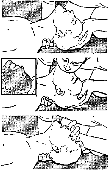
(“Mouth to mouth” resuscitation) Figure 1
(1) Place the victim’s head facing backward (place something under the neck like a pillow).
(2) Point the chin upward to widen the trachea.
(3) Pinch the victim’s nose, take a deep breath, then put your mouth over the victim’s mouth and
exhale completely, making sure that your mouth completely covers the victim’s mouth.
Then remove your mouth. Repeat this routine 10 to 15 times per minute (holding the
nostrils).
(4) Pay attention to the victim to notice if he or she starts to breath. If breathing returns, stop
resuscitation.
(5) If it is impossible to open the victim’s mouth, put something like a plastic straw or vinyl tube
into one of the nostrils then blow air in while covering the mouth and the other nostril.
(6) Occasionally, when the victim comes back to consciousness, they immediately try to stand
up. Prevent this and keep them in a laying position. Give them something warm to drink
and be sure that they rest (do not give them any alcohol).
Administering artificial respiration by raising the head.
① (1) Raise the back of head, then place one
hand on the forehead and place the
other hand under the neck. →①
Most victims open their mouth when this
is done, making “mouth to mouth”
resuscitation easier.
② (2) Cover the victim’s mouth by opening
your mouth widely, then push your cheek
against the victim’s nose, →②
or pinch the victim’s nose to prevent air
from leaking out of it. →③
③ (3) Completely exhale into the lungs.
Exhale into the lungs until the chest
inflates.
You have to blow as rapidly as possible
for the first 10 times.
“Mouse to mouse” artificial respiration
Figure 1

☆If the victim has no pulse and is not breathing
(Heart massage in combination with artificial respiration.) Figure 2
If the victim has no pulse, his or her pupils are dilated, and if you cannot detect a heartbeat, the
heart may have stopped, beginning artificial respiration is critical.
(1) Put both hands on the diaphragm, with hands on top of each other keeping both arms straight
(If your elbows are bent, you cannot push with as much power). Press the diaphragm with
your body weight until the chest sinks about 2 cm (about 50 times per minute).
(2) If administering first aid when alone:
Perform the heart massage about 15 times then blow in twice. Repeat this routine.
If administering first aid with two people:
One person performs the heart massage 5 times, and the other person blows air in once.
Repeat this routine (Heart massage and “mouth to mouth” resuscitation used together).
(3) Constantly check the pupils and the pulse, if the pupils become normal and the pulse steadies,
keep them in a laying position and give them something warm to drink, be sure that they rest
(do not give them any alcohol). In any case you have to entrust major decision making to a
doctor. Having understanding people around is essential to the victim’s recovery from the
mental shock of electrocution.
① ②
③ ④
(Heart massage in combination with artificial respiration.) Figure 2
i
Preface
Thank you for choosing the Model JRC JHS-770S/780D Marine VHF Radiotelephone. This
radiotelephone can be used as a Global Maritime Distress and Safety System (GMDSS) radio
device, compliant with international regulations, that provides emergency communications and
standard communications capabilities for small and large ships.
● Please read this instruction manual thoroughly before using the JHS-770S/780D Marine VHF
Radiotelephone, and use it in accordance with the instructions contained herein.
● Please keep this manual available for future reference. Please refer to it if any difficulties
are encountered when using the equipment.
FCC Warning
Changes or modifications not expressly approved by JRC, could void your
authority to operate this radiotelephone.
Radio Frequency Interference Statement
This radiotelephone has been tested and found to comply with the limits for a
Class A digital device, pursuant to part 15 of the FCC Rules. These limits
are designed to provide reasonable protection against harmful interference
when the equipment is operated in a commercial environment. This
radiotelephone generates, uses, and can radiate radio frequency energy and,
if not installed and used in accordance with the instruction manual, may
cause harmful interference to radio communications. Operation of this
radiotelephone in a residential area is likely to cause harmful interference in
which case the user will be required to correct the interference at his own
expense.
RF exposure compliance (MPE* compliance by FCC)
The antenna used for this transmitter must be installed to
provide a separation distance of at least 0.9 meters (3 feet)
from all persons and must not be co-located or operating in
conjunction with any other antenna or transmitter. Users
and installers must be provided with antenna installation
instructions and transmitting operating conditions for
satisfying RF exposure compliance.
* Maximum Permissible Exposure (MPE): The rms and peak electric
and magnetic field strength, their squares, or the plane-wave
equivalent power densities associated with these fields to which a
person may be exposed without harmful effect and with an acceptable
safety factor.
ii
Before Operation
Concerning the symbols
This manual uses the following symbols to explain correct operation and to prevent injury or
damage to property.
The symbols and descriptions are as follows. Understand them before proceeding with this
manual.
WARNING Indicates a warning that, if ignored, may result in
serious injury or even death.
CAUTION Indicates a caution that, if ignored, may result in injury
or damage to property.
Examples of symbols
The Δ symbol indicates caution (including DANGER and WARNING). The
illustration inside the Δ symbol specifies the content of the caution more
accurately. (This example warns of possible electrical shock.)
The ; symbol indicates that performing an action is prohibited. The illustration
inside the ; symbol specifies the contents of the prohibited operation. (in this
example disassembly is prohibited.)
The z symbol indicates operations that must be performed. The illustration
inside the z symbol specifies obligatory instructions. (In this example
unplugging is the obligatory instruction.)
iii
Handling precaution
WARNING
Do not open the equipment to inspect or repair it. Inspection or repairs by anyone other
than a specialized technician may result in fire, electrical shock, or malfunction.
If internal inspection or repair is necessary, contact our service center or agents.
Do not disassemble or customize this unit. Doing so may cause fire, electrical shock, or
malfunction.
Do not get this equipment wet or spill any liquids on or near this equipment.
Doing so may cause electrical shock or equipment malfunction.
Do not touch any of the areas with warning labels.
Doing so may cause electrical shock.
Do not use a voltage other than specified.
Doing so may cause fire, electrical shock, or malfunction.
Do not remove protective covers on the high voltage terminals.
Doing so may cause electrical shock.
Do not insert anything flammable into the equipment.
Doing so may cause fire, electrical shock, or malfunction.
If a distress call is received, make sure to inform the ship's captain or officer in charge.
This affects life of the crews and passengers on the ship in distress.
This unit is also used for the distress communication, in addition to usual communication.
Contact JRC or our agent if any problem is observed in this unit on usual operation or
inspection. Do NOT ignore or leave any problems of this unit.
Always use the specified fuse when replacing a fuse. Using a different fuse may result
in fire or malfunction.
Before replacing fuses of the POWER SUPPLY (NBD-865), always turn off the AC/DC
power switch and power source output to this unit.
In addition to the AC fuse on the panel of the POWER SUPPLY (NBD-865), there are also
DC fuses contained in the unit. Opening and working with the inside of the unit may
result in fire or electrocution, so with the exception of qualified service personnel, do NOT
attempt to replace the DC fuses. To replace the DC fuses, contact JRC or our agent.
iv
Handling precaution
CAUTION
Do not use this equipment for anything other than specified.
Doing so may cause failure or malfunction.
Do not turn the trimmer resistors or the trimmer capacitors on the PCB unit. Doing so
may cause failure or malfunction. They are preset at the factory.
Do not install this equipment in a place near water or in one with excessive humidity,
steam, dust or soot. Doing so may cause fire, electric shock, or malfunction.
Do not test the distress call as doing so will inconvenience local shipping and Rescue
Centers.
Do NOT turn off the power of the equipment when at sea because the SOLAS
Convention requires keeping CH16 watch at all times.
Always listen to CH16 except when talking on a specific channel.
To operate DSC and ATIS functions of this equipment, ID numbers must be registered
respectively. If not been registered, contact our agent or service center.
Leave installation of this equipment to our service center or agents. Special knowledge
on selecting the place where the antenna is to be mounted and setting the ID number
(MMSI) assigned to the ship is required besides mounting operation.
When sending a distress call, follow the instructions of the ship's captain or officer in
charge.
If a false distress call (distress alert) is transmitted accidentally, follow the instructions
below:
1. Press the CANCEL key on the controller (when appropriate, follow the commands
on screen) and terminate the transmission of the distress call.
2. Report the false distress call to a nearby RCC (Rescue Coordination Center).
(In Japan, inform the nearest Japan Coast Guard.)
Information to be reported:
The date/time, location, and reason why the false call was transmitted. Also report
the ship's name, type, nationality, ID number as well as the unit model name and
manufacture number/date, if possible.
3. Report the false distress call to nearby ships using CH16.
4. If any acknowledgements to the distress call are received, inform the ships of the
false distress call.
v
CAUTION
To turn off an alarm or clear a display such as a received DSC message, do NOT press the
DISTRESS key. Doing so may cause a false distress call.
(Press the CANCEL key to turn off the alarm and delete the on screen message.)
When sending a proxy distress call (DROBOSE), do NOT press the DISTRESS key.
Doing so will inconvenience local shipping and Rescue Centers. (This proxy distress call
can be sent via [Call] button displayed on the screen.)
A distress acknowledgement or a distress relay call can be transmitted from a received
distress message stored in the log, but when sending such a kind of call, follow the
instructions of the ship's captain or officer in charge.
In order to avoid accidental distress message treating, received distress messages will be
erased automatically after 48 hours elapsed since the reception. Accordingly, if such
messages cannot be read out, it is NOT a malfunction.
The time in the menu 9.1.2 Present time is different from the time in the menu 9.2.2 UTC
of position that means the time when the position information is valid.
The time in the menu 9.2.2 UTC of position means the time when the position information
is valid, and is different from the present time mentioned above.
Close the water-resistant cap of the waterproof type handset box after use. Rain and sea
breeze could cause connector malfunction. Also do not leave the handset above deck.
The thermal head of the printer may be very hot after printing. Do not touch it.
Perform paper replacement and head cleaning only after waiting for the head to
completely cool.
The printing paper used in this printer is a heat sensitive paper. Take the following
precautions when using this paper.
· Store the paper away from heat, humidity, or heat sources.
· Do not rub the paper with any hard objects.
· Do not place the paper near organic solvents.
· Do not allow the paper to come in contact with polyvinyl chloride film, erasers, or
adhesive tape for long periods of time.
· Keep away the paper from freshly copied diazo type or wet process copy paper.
For the CHANNEL SELECTOR (NCM-2000) installed above deck, close the water-
resistant cap after use. Rain and sea breeze could cause connector malfunction. Also
do not leave the handset above deck.
vi
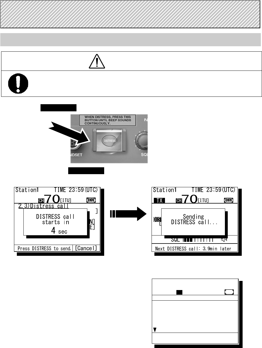
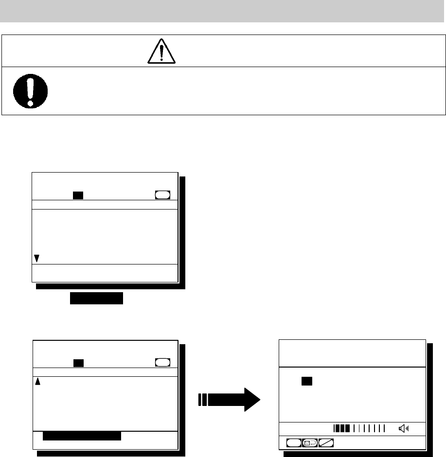
Sending a Distress Call (Distress Alert)
CAUTION
When sending a distress call, follow the instructions of the ship's captain or officer in charge.
1
1
1.
.
.
Open the DISTRESS key cover on the NCM-1770 CONTROLLER.
2
2
2.
.
.
Press and hold the DISTRESS key for 4 seconds. (See the note below.)
When completed the countdown and displayed the screen at right below, the distress call is transmitted.
3
3
3.
.
.
After sending the distress call, wait for an acknowledgement.
Radiotelephone can communicate even while
waiting for an acknowledgement.
When receiving a distress acknowledgement, the
right screen is displayed. Unless received the
distress acknowledgement or cancelled the
distress call mode manually, this equipment
repeats the distress call sending every 3.5 to 4.5
minutes automatically.
4
4
4.
.
.
After receiving acknowledgement, lift the handset and request rescue using CH16 of
the radiotelephone.
First, the responding station calls by radiotelephone. Communicate the following information to that
station.
z Say "MAYDAY",
z Say "This is (name of your ship)",
z Tell the ship's Maritime Mobile Service Identity (MMSI) number, call sign, ship's position,
nature of distress, and rescue requests
DISTRESS CALLS
Received Acknowledgement
Type :Distress ACK...
To :All ships .....
From :001234567......
Dist-ID :987654321......
Nature :Fire...........
Position :34゚00.1234'N...
Station1 TIME 23:59(UTC)
16
CH70
Press CANCEL to silence alarm.
CH [ITU]
vii
If time permits, enter the nature of the distress as follows, just before the distress
call. (For more details, see 4.4.3.2.)
1) Press the DISTRESS key momentarily
to open the menu 2.3 Distress call.
2) Press ENT and select the nature of distress.
3) Press ENT to determine the selection.
If not displayed the position and the time (UTC)
automatically for any reason, input them manually
at this time.
4) Press and hold the DISTRESS key for
4 seconds to send the distress call.
The rest of the procedure is the same as described above.
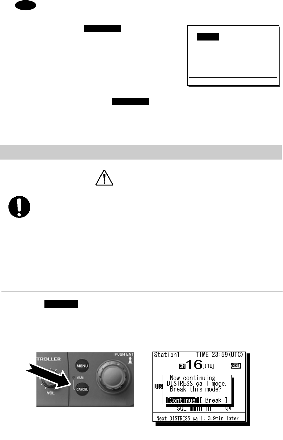
Terminating Transmission of a Distress Call
CAUTION
If a false distress call is transmitted accidentally, follow the instructions below:
1. Immediately terminate the distress call according to the following procedure.
2. Report the false distress call to a nearby RCC (Rescue Coordination Center).
(In Japan, report to the Japan Coast Guard.)
Information to be reported:
The date/time, location, and reason why the false call was transmitted. Also report the
ship's name, type, nationality, ID number as well as the unit model name and
manufacture number/date, if possible.
3. Report the false distress call to nearby ships using CH16.
4. If any acknowledgements to the distress call are received, inform the ships of the false
distress call.
1
1
1.
.
.
Press the CANCEL key.
If the CANCEL key is pressed during transmission of the distress call, immediately returns to the status
display.
If the CANCEL key is pressed in the interval between automatic resending of the distress call, the
screen as shown below will be displayed. Select Break and press ENT with the jog dial to return to the
status display.
Note
2.3)Distress call
Nature :[Undesignated ]
Position:[NE]
[ 12゚34.5678'S]
[123゚45.6789'W]
UTC :[12:20]
Press DISTRESS to send.
[Cancel]
viii
Receiving a Distress Call
WARNING
If a distress call is received, make sure to inform the ship's captain or officer in charge.
Doing so may save the lives of the crew and passengers on the ship in distress.
1
1
1.
.
.
When a distress call is received, the message will be displayed.
The ALM light will start blinking, and an alarm will sound growing louder gradually.
2
2
2.
.
.
Press the CANCEL key to stop the alarm, and then press ENT and keep watch on
CH16.
Keep watch on CH16 for at least 5 minutes, and notify the coast station as appropriate.
3
3
3.
.
.
When responding due to watching on CH16 and coordinating with the coast station,
select the menu of 4.1 Received distress list and send the acknowledgement. After
sending it, commence distress traffic via radiotelephony on CH16 as follows.
z Say "MAYDAY",
z Repeat the identity (MMSI) of the ship in distress 3 times,
z Say "This is",
z Repeat the identity (MMSI) of your ship 3 times,
z Say "RECEIVED MAYDAY".
Station1 TIME 23:59(UTC)
POS 89゚59'S
EXT 179゚59'W
16
CH
SQL
CH70
CHSW
[ITU]
Received distress message
Type :Distress.......
From :431001234......
Nature :Fire...........
Position :12゚34.5678'N...
123゚45.6789'E..
UTC :12:14..........
Station1 TIME 23:59(UTC)
16
CH70
Press CANCEL to silence alarm.
CH [ITU]
Received distress message
From :431001234......
Nature :Fire...........
Position :12゚34.5678'N...
123゚45.6789'E..
UTC :12:14..........
EOS :EOS
Station1 TIME 23:59(UTC)
16
CH70
[OK/CH16 watch] [Cancel]
CH [ITU]
ix
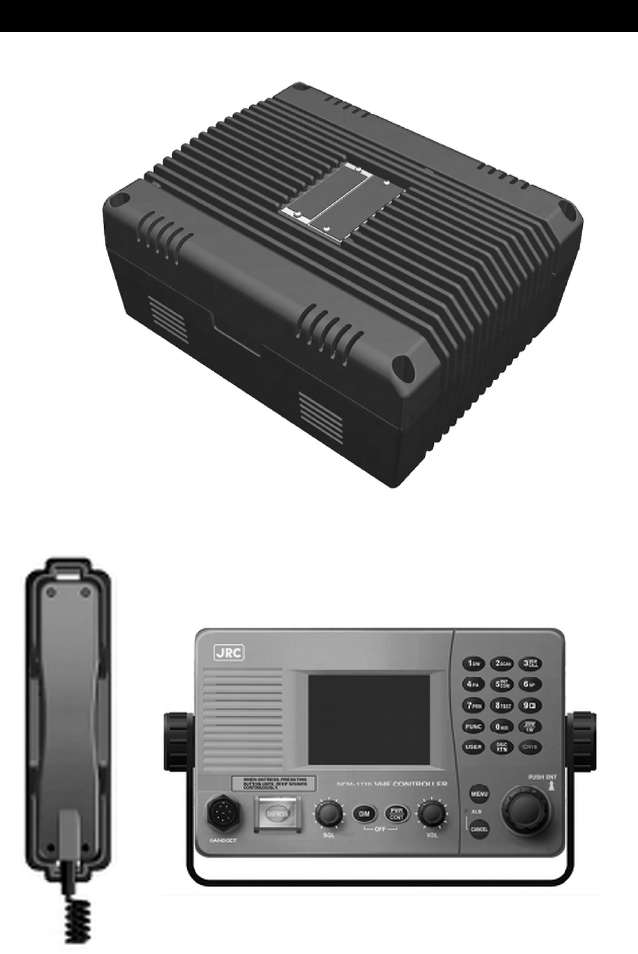
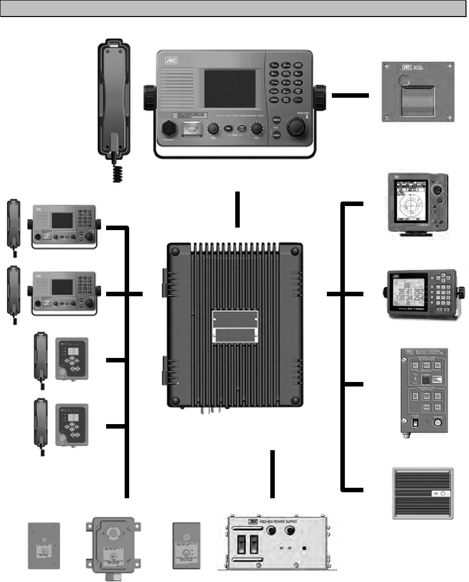
Equipment exterior
● JHS-770S/780D VHF Marine Radiotelephone
NTE-770S/780D VHF Transceiver
NCM-1770 VHF Controller / NQW-261 Handset
x
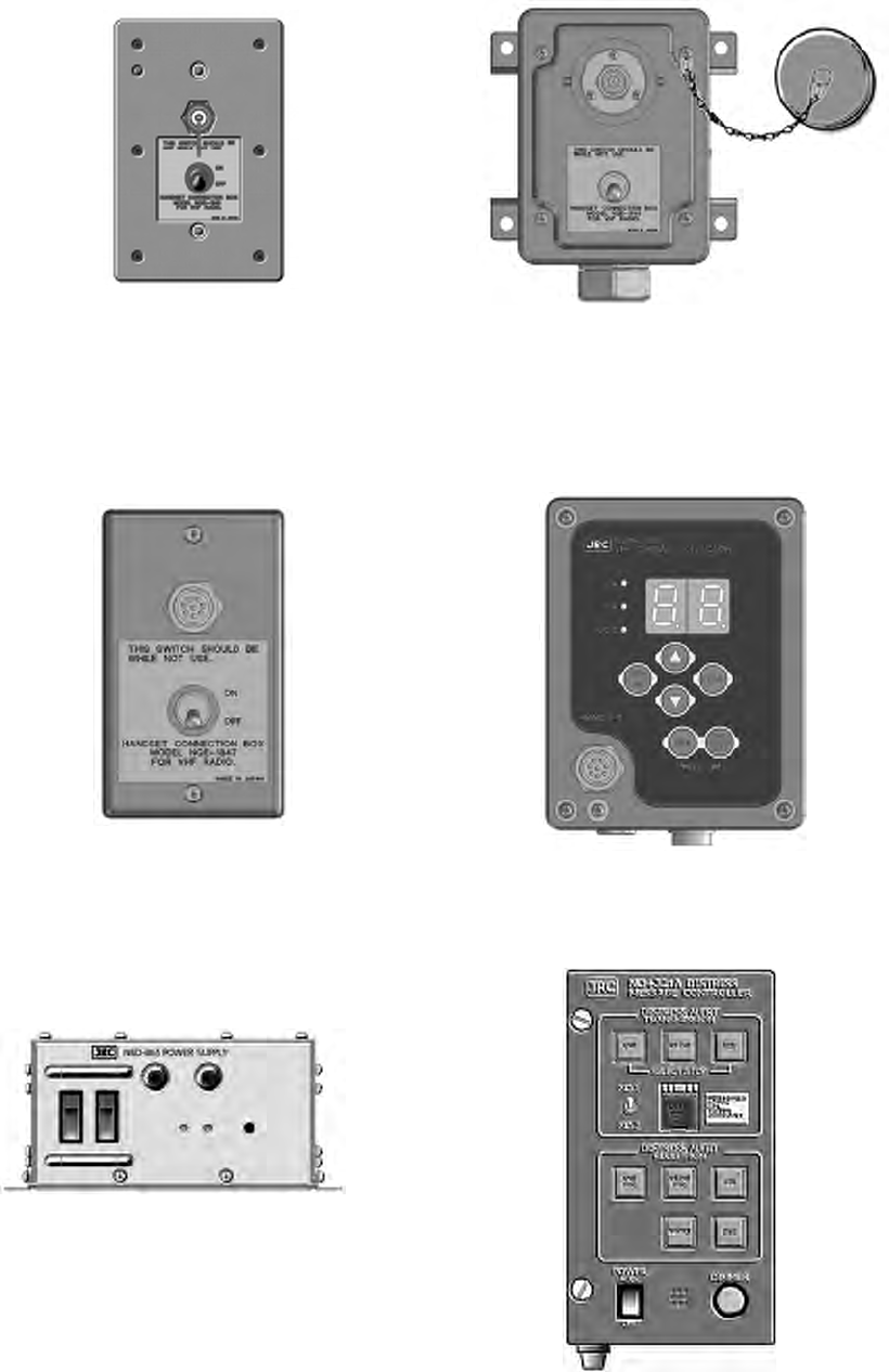
● NQE-1845 Handset Connector Box
Waterproofed flush mount type
(for wing console)
● NQE-1846 Handset Connector Box
Waterproofed wing installation type
● NQE-1847 Handset Connector Box
Indoor flush mount type
● NCM-2000 VHF Channel Selector
● NBD-865 AC/DC Power Unit
● NCH-321A Distress Message Controller
xi
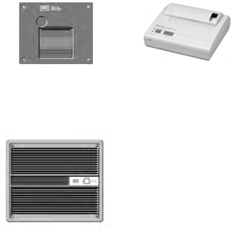
● NKG-91 Printer
● DPU-414 Printer
● NVS-423R External Speaker

xii
Contents
Preface ............................................................................ i
Before operation ............................................................. ii
Handling precaution ....................................................... iii
DISTRESS CALL ............................................................. vi
Equipment exterior ......................................................... ix
Glossary of terms ........................................................... xvi
1 EQUIPMENT OVERVIEW ........................................... 1-1
1.1 Functions ..................................................................................................................... 1-1
1.2 Features ...................................................................................................................... 1-1
1.3 Basic configuration ...................................................................................................... 1-2
1.3.1 Basic configuration of the main unit .................................................................... 1-2
1.3.2 Options ................................................................................................................ 1-2
1.3.3 System configuration ........................................................................................... 1-3
1.4 External dimensions .................................................................................................... 1-4
1.5 Block diagram .............................................................................................................. 1-13
2 NAMES AND FUNCTIONS ......................................... 2-1
2.1 Controller (NCM-1770) ................................................................................................ 2-1
2.2 Main displays ............................................................................................................... 2-3
2.2.1 Status display ...................................................................................................... 2-3
2.2.2 Menu screen ........................................................................................................ 2-4
2.2.3 DSC message receiving screen .......................................................................... 2-5
3 INSTALLATION ........................................................... 3-1
4 OPERATION ................................................................ 4-1
4.1 Controller operation overview ...................................................................................... 4-1
4.2 Basic communication procedure ................................................................................. 4-3
4.2.1 Turning ON the power ......................................................................................... 4-3
4.2.2 Turning OFF the power ....................................................................................... 4-4
4.2.3 Communicating with the radiotelephone ............................................................. 4-5
4.2.4 Receiving with scanning ...................................................................................... 4-7
4.2.5 Receiving with dual watch ................................................................................... 4-8
4.2.6 Using memory channels ...................................................................................... 4-9
4.2.7 Communicating on a private channel .................................................................. 4-11
4.2.8 Receiving a weather channel .............................................................................. 4-11
4.2.9 Changing the channel region .............................................................................. 4-12
xiii
4.2.10 Squelch settings of each channel (preset squelch) ............................................. 4-13
4.3 Basic DSC operations .................................................................................................. 4-14
4.3.1 Routine calls to a coast station ............................................................................ 4-14
4.3.2 Routine calls to a ship station .............................................................................. 4-16
4.3.3 Receiving a routine call ........................................................................................ 4-17
4.3.4 Communicating with a PSTN subscriber ............................................................. 4-20
4.3.5 AIS-linked DSC calls ............................................................................................ 4-23
4.4 Emergency calls (DSC Safety/ Urgency/ Distress Calls) ............................................. 4-25
4.4.1 Safety calls ........................................................................................................... 4-25
4.4.1.1 All ships calls .................................................................................................... 4-25
4.4.1.2 Individual calls (All modes RT) ........................................................................... 4-26
4.4.1.3 Other features of the safety call (Position request/ Test) .................................. 4-28
4.4.1.4 Receiving a safety call ...................................................................................... 4-30
4.4.2 Urgency calls ........................................................................................................ 4-32
4.4.2.1 All ships calls .................................................................................................... 4-32
4.4.2.2 Individual calls .................................................................................................. 4-33
4.4.2.3 Special calls (Medical transport/ Neutral ship) .................................................. 4-35
4.4.2.4 Receiving an urgency call ................................................................................. 4-36
4.4.3 Distress calls (Distress alerts) .............................................................................. 4-38
4.4.3.1 Quick distress calls ........................................................................................... 4-38
4.4.3.2 Distress calls from the menu ............................................................................ 4-40
4.4.3.3 Receiving a distress call ................................................................................... 4-42
4.4.3.4 Acknowledgement to a received distress call ................................................... 4-43
4.4.4 Distress relay calls on behalf of someone else (Proxy distress calls) ................. 4-44
4.4.4.1 All ships calls .................................................................................................... 4-44
4.4.4.2 Coast station calls ............................................................................................. 4-46
4.4.4.3 Receiving a proxy distress call ......................................................................... 4-49
4.4.5 Distress relay calls ............................................................................................... 4-50
4.4.5.1 Sending a distress relay call ............................................................................. 4-50
4.4.5.2 Receiving a distress relay call .......................................................................... 4-52
4.5 Simple DSC test call .................................................................................................... 4-54
4.6 DSC call log ................................................................................................................. 4-55
4.6.1 Received distress messages ............................................................................... 4-55
4.6.2 Received other messages ................................................................................... 4-56
4.6.3 Transmitted messages ......................................................................................... 4-57
4.7 Other features .............................................................................................................. 4-58
4.7.1 Notification of registered ships by the AIS ........................................................... 4-58
4.7.2 Playback of received voice .................................................................................. 4-59
4.7.3 Public Address function with an external speaker (option) .................................. 4-62
4.7.4 Intercom ............................................................................................................... 4-63
4.8 Popup screens ............................................................................................................. 4-65
xiv
5 SETTINGS & REGISTRATIONS ................................. 5-1
5.1 Date and time setting .................................................................................................. 5-1
5.2 Own ship position and time setting .............................................................................. 5-3
5.3 Settings for each controller .......................................................................................... 5-4
5.3.1 LCD adjustment ................................................................................................... 5-4
5.3.2 Sound settings ..................................................................................................... 5-4
5.3.3 User key assignment ........................................................................................... 5-5
5.3.4 Name a controller ................................................................................................ 5-6
5.3.5 Disabling the hook switch .................................................................................... 5-7
5.4 Creating contact lists ................................................................................................... 5-8
5.5 Advanced settings for DSC ......................................................................................... 5-11
5.5.1 Automatic acknowledgement .............................................................................. 5-11
5.5.2 Disabling the automatic channel shift .................................................................. 5-11
5.5.3 Disabling receiving alarms for routine and safety calls ....................................... 5-12
5.5.4 Medical/Neutral use setting for urgency calls ..................................................... 5-12
5.5.5 Expanded MMSI registration ............................................................................... 5-12
5.6 Other settings .............................................................................................................. 5-13
5.6.1 Enabling the AIS function .................................................................................... 5-13
5.6.2 Printer property .................................................................................................... 5-14
6 MAINTENANCE & INSPECTION ................................ 6-1
6.1 General maintenance & inspection ............................................................................. 6-1
6.2 Self diagnosis inspection ............................................................................................. 6-2
6.3 System alarm indication .............................................................................................. 6-4
6.3.1 Alarm list .............................................................................................................. 6-5
6.3.2 Viewing the alarm history .................................................................................... 6-6
6.4 Checking the setup condition ...................................................................................... 6-7
6.4.1 System information .............................................................................................. 6-7
6.4.2 Software version .................................................................................................. 6-7
6.5 DSC AF inspection ...................................................................................................... 6-8
6.6 Troubleshooting ........................................................................................................... 6-9
6.6.1 Procedures for locating malfunctions .................................................................. 6-9
6.6.2 Guide to locating faults ........................................................................................ 6-10
6.6.3 Repair units/parts ................................................................................................ 6-11
6.6.4 Regular replacement parts .................................................................................. 6-11
7 AFTER-SALES SERVICE ........................................... 7-1
8 DISPOSAL .................................................................. 8-1
9 SPECIFICATIONS ....................................................... 9-1
9.1 JHS-770S/780D Marine VHF Radiotelephone ............................................................ 9-1
9.2 Channel assignment tables ......................................................................................... 9-4
9.3 Options ........................................................................................................................ 9-9
xv
9.4 Peripheral interfaces .................................................................................................... 9-10
10 OPTIONS OPERATION .............................................. 10-1
10.1 Handset connection box (NQE-1845/ 1846/ 1847) ...................................................... 10-1
10.2 AC/DC Power supply (NBD-865) ................................................................................. 10-2
10.3 Printer (NKG-91) .......................................................................................................... 10-3
10.4 VHF Channel selector (NCM-2000) ............................................................................. 10-4
Appendix) Declaration on toxic& hazardous substances or elements (1/1)

xvi
Glossary of terms
This section contains general and DSC terms related to this equipment.
● General terms
AIS(Automatic Identification System)
Equipment that transmits a ship's Maritime Mobile
Service Identity number, ship name, ship position,
speed, orientation, and other information to and
from other ships. AIS equipment is required on
some ships by the International Convention for
the Safety of Life at Sea (SOLAS)
ATIS
(
Automatic Transmitter Identification System
)
This is used for notification of the radio station ID
to receivers when using European inland
waterway (IWW) channels.
CCG(Canadian Coast Guard)
Canadian Coast Guard
DSC(Digital Selective Calling)
Used in routine calls, safety and urgency calls,
and distress calls for rescue request.
GMDSS
(
Global Maritime Distress and Safety System
)
Global Maritime Distress and Safety System
GPS(Global Positioning System)
Global Positioning System
IMO
(
International Maritime Organization
)
International Maritime Organization
Intercom
Wired communications equipment or functionality
ITU
(
International Telecommunication Union
)
The leading United Nations agency for
information and communication technologies.
Establishes conventions and regulations for all
electrical communications. It contains internal
organizations such as ITU-R and ITU-T.
ITU-R
The International Telecommunication Union (ITU)
radio communications department
IWW(Inland Waterway)
Inland Waterway
LT(Local Time)
Local Time
MMSI(Maritime Mobile Service Identity)
The 9-digit Maritime Mobile Service Identity
number assigned to each ship and coast station.
NMEA
(
National Marine Electronics Association
)
Maritime equipment transmission standard
established by the National Marine Electronics
Association
NNSS
(
Navy Navigation Satellite System
)
Doppler based satellite positioning system
operated by the United States Navy.
PA(Public Address)
Sound amplification equipment
In this radiotelephone equipment, it is a function
for using an external public address.
PTT(Push To Talk)
Handset button pressed to talk
RCC(Rescue Co-ordinate Center)
In Japan, the Japan Coast Guard.
RMS(Remote Maintenance System)
Transmits ship equipment information temporarily
stored in VDR via Inmarsat to land, for use in
maintenance and management of radio
equipment.
RR(Radio Regulations)
Intergovernmental treaty text of the ITU
SAR Convention
(
International Convention
on Maritime Search and Rescue
)
International Convention on Maritime Search and
Rescue
SOLAS Convention
(
International Convention
for Safety of Life at Sea
)
The international convention applied to all ships
engaged on international voyages. A safety
certificate is issued if the conditions of this
convention are satisfied.
SQL(Squelch)
A function that acts to suppress the audio
output of a receiver in the absence of a
sufficient radio strength signal.
Station
A radio station, or a control terminal for radio
equipment

xvii
USCG(United States Coast Guard)
United States Coast Guard
UTC(Universal Time Coordinated)
Universal Time Coordinated
VDR(Voyage Data Recorder)
After a maritime accident, recovered to analyze
the recorded data (speed, rudder, bridge
conversation, VHF audio, etc.) to determine the
cause of the accident.
It can also transmit navigation management data
regularly via Inmarsat to land.
VHF(Very High Frequency)
Very High Frequency (30 - 300MHz)
VOL(Volume)
Internal speaker volume
WRC
(
World Radiocommunication Conference
)
World Radiocommunication Conference
WMO
(
World Meteorological Organization
)
World Meteorological Organization
WKR(Watch Keeping Receiver)
Dedicated receiver for CH70 to watch the DSC
signals.
● DSC terms
Address
General term for Maritime Mobile Service Identity
number (MMSI)
This equipment uses To/From to distinguish
between the sender and receiver. It also means
the Self-ID (own ship MMSI) and Dist-ID (MMSI of
a ship in distress).
Category
Message code indicating priority of the call.
It contains types as below.
・ Routine ........General calls for routine works
・ Safety ..........Safety communications call
・ Urgency .......Urgent communications call
・ Distress........Distress call (Distress alert)
EOS(End Of Sequence)
Termination code appended to the call messages.
It contains types as below.
・ EOS .............End of sequence
・ ACK RQ.......Acknowledgement request
・ ACK BQ .......Acknowledgement responding to
the ACK RQ
ECC(Error Check Character)
Error check code appended to the end of call
messages.
This is not normally displayed, but if an error
occurs, one of the following will be displayed.
・ ECC error ....Message error
・
Ex ECC error
....Expansion
message error
Format
Message code indicating type of call.
It contains types as below.
・ Individual call .........Individual call
・ Individual ACK .......Acknowledgement
response to individual call
・ Individual NACK ....Negative acknowledgement
response to individual call
・ Semi/auto call........PSTN connection call
・ Semi/auto ACK ...... PSTN call
acknowledgement
・ Semi/auto NACK ... PSTN call negative
acknowledgement
・ Group call ..............Call to ships having
common interest
・ All ships call...........Call to all ships
・ Distress ................. Distress call
Nature of Distress
Message code indicating type of distress when a
distress call is issued.
It contains types as below.
・ Fire ........................ Fire, explosion
・ Flooding ................ Flooding
・ Collision.................Collision
・ Grounding.............. Grounding
・ Listing .................... Risk of ship capsizing
・ Sinking .................. Sinking
・ Disabled ................ Ship inoperable/adrift
・ Undesignated ........Undesignated distress
・ Abandoning ........... Abandoning ship
・ Piracy attack.......... Piracy attack
・ Man overboard ...... Man overboard
・ EPIRB emission ....DSC VHF EPIRB reception
Polling
Polling is a feature for routine calling.
It is used, for example, to confirm whether a ship
is existing within radio range when a coast station
requests navigational information to the ship.

xviii
PSTN(
Public Switched Telephone Network
)
General fixed landline telephone network.
Reason
Message code indicating reason for negative
acknowledgement response.
・ No reason ............. No reason
・ Congestion............ Maritime information
exchange center congested
・ Busy...................... Busy
・ Queue ................... Queued
・ Barred ................... Station barred
・ No operator........... No operator
・ Temp no oper........ Temporarily no operator
・ EQP disabled........ Equipment disabled
・ Unable channel..... Indicated channel cannot
be used
・ Unable mode… ..... Indicated mode cannot be
used
Subject
Message code clarifying communication contents
when sending an urgency call to all ships.
When sailing dangerous waters, such as political
instability, these call messages with the following
information are used.
・ Neutral ship........... In accordance with ITU
resolution 18 (Mob-83),
inform all ships that own
ship is of neutral nationality.
・ Medical TRNSP .... Inform all ships that own
ship is performing medical
transportation, and is
protected under the 1949
Geneva Convention.
Type
Main contents of call message.
Normally, the 1st telecommand will be indicated,
but for a distress related call, it may also take into
account the Format and the EOS. Displayed
when message is received, as well as in LOG.
・ All modes RT .........All F3E/G3E
radiotelephones
・ Duplex RT..............Duplex F3E/G3E
radiotelephones
・ Polling....................Polling
・ Data .......................Data transmission
・ Position RQ ...........Ship position request
・ Ship position ..........Ship position notification
・ Test........................Safety test call
・ Unable to
comply
....Negative acknowledgement
・ Distress..................Distress call message
・ Distress ACK .........Acknowledgement of
distress call message
・ Distress relay.........Distress relay message
・ Dist-relay ACK .......Acknowledgement of
distress relay message
・ Proxy distress ........Distress relay message on
behalf of someone else
・ Proxy dist-ACK ......Acknowledgement of
distress relay call on behalf
of someone else
Work CH
Message code indicating a work channel to
communicate using radiotelephone.

Equipment Overview
1-1
1. EQUIPMENT OVERVIEW
1.1 Functions
This equipment includes VHF radiotelephone, Class-A DSC and DSC watchkeeping receiver
required as the Global Maritime Distress and Safety System (GMDSS). It is designed as a
separated transceiver and small, lightweight controller(s) for easy installation not only in
international passenger ships and freight ships of 300 tons or more, but also conventional ships of
less than 300 tons.
It has the radiotelephone, the DSC communication functions, received voice recording and
playback function, and self-diagnosis function with simple operation using a dedicated key.
Additionally, it offers such as public address function using an external speaker, intercom function
for communication between controllers, and the DSC calling function using an automatic
identification system (AIS) information.
1.2 Features
● Compliant with the ITU Radio Regulations (RR), the IMO performance standards, and the
ITU-R recommendations.
● Contains all channels specified in the ITU Radio Regulations (RR).
● In addition to channels specified in the ITU Radio Regulations (RR), this equipment also
provides USA, Canada, European inland waterway, and weather channels. It also allows the
use of up to 200 private channels.
● Contains ATIS (Automatic Transmitter Identification System) function for the inland waterway
channels.
● Separately designed transceiver and controller enable easy installation in limited or difficult
spaces.
● A semi-transmissive LCD with a wide viewing angle features easily viewable even when with
straight light or backlit and allows it to install variety positions.
● The backlights of the LCD and operation keys are fully adjustable, preventing interference
with night watch keeping.
● The DSC is very easy to operate, especially a routine call, which can be sent by pressing the
dedicated routine call key and selecting address only. Additionally prepared a dedicated
menu for DSC safety test calling to make a radio communication inspection simple.
● When in distress, the DSC can send the distress message with the expanded position data
containing the digits up to 1/10000 of minutes for both latitude and longitude to make search
and rescue operation by the RCC easier.
● The received voice recording and playback function enables later confirmation or temporary
saving of communications.
● An advanced digital audio amplifier with a built-in loud speaker provides 5Wmax of clear audio.
● A dedicated self-diagnosis key makes maintenance and inspection simple.
● Besides printers and GPS, other peripherals such as the AIS, the VDR, and/or remote
maintenance systems (RMS) can be connected to this equipment.

Equipment Overview
1-2
1.3 Basic configuration
1.3.1 Basic configuration of the main unit
No. Product Name Model Name Qty Notes
1 VHF Transceiver NTE-770S,
or NTE-780D 1 NTE-770S: JHS-770S,Simplex
NTE-780D : JHS-780D,Duplex
2 VHF Controller NCM-1770 1
Includes the connection cable
(7ZCJD0299A)
3 Handset NQW-261 1 Includes the cradle
4 Instruction Manual 7ZPJD0406A 1 This manual
1.3.2 Options
No. Product Name Model Name Notes
1 TRX Antenna 7ABJD0004 1.29m Dipole type
2 WKR Antenna 7ABJD0004 1.29m Dipole type
3 Antenna mounting bracket MPBX41928A Used for each antenna
4 Coaxial connector N-P-10U
5 AC/DC Power supply NBD-865
6 VHF Controller NCM-1770
6-1 Flush mounting bracket MPBC42957
6-2 Mounting bracket MPBX44354
Up to 2 additional controllers available.
7 VHF Channel selector NCM-2000 Waterproof type (IP66 equivalent)
7-1 Connection box NQE-7720 For stand-alone installation above deck
8 Connection box NQD-2770 For connecting additional controllers or
channel selectors
9 Handset NQW-261 Waterproof type (IP66 equivalent)
For controllers and channel selectors
10 Handset connection box NQE-1845
Wing console/ flush mount type
(IP66 equivalent)
11 Handset connection box NQE-1846 Wing installation type (IP66 equivalent)
12 Handset connection box NQE-1847 Indoor flush mount type
13 Printer NKG-91
13-1 Printer connection cable 7ZCJD0254A
13-2 Printer paper 7ZPJD0384
13-3 Wall mounting bracket MPBP31446
Wall mount or flush mount type
14 Printer DPU-414
14-1 Printer connection cable 7ZCJD0254A
14-2 Printer power cable 7ZCJD0257C
14-3 Printer paper 6ZCAF00252A
Desktop type
15 Extension board CQD-7701 For optional peripherals
16 External speaker NVS-423R Wall mount type
17 Distress message controller NCH-321A
Equipment Overview
1-3
1.3.3 System configuration
NBD-865 Power Supply
NCH-321A DMC
GPS
AIS
NKG-91 Printer
NCM-1770 Controller
NTE-770S/780D Transceiver
NVS-423R Speaker
Additional Controller or
Channel Selector
Indoor
Handset
Connection Box
* The radiotelephone
can also be used with
connected remote
maintenance systems
and VDR equipment.
Waterproofed
Handset
Connection Box
Waterproofed
Handset
Connection Box
Equipment Overview
1-4
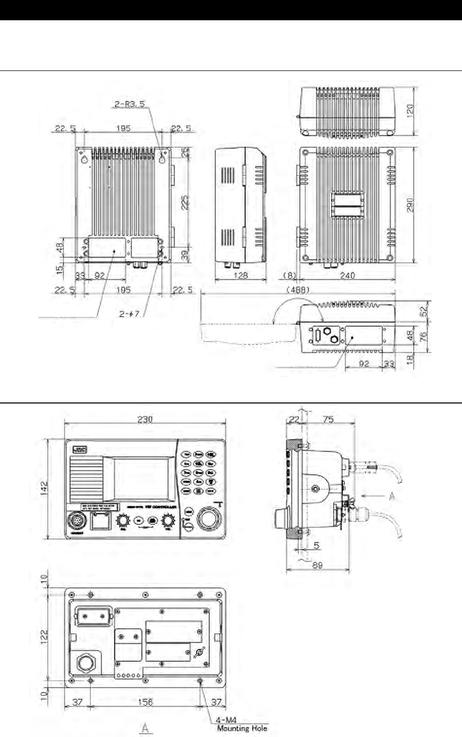
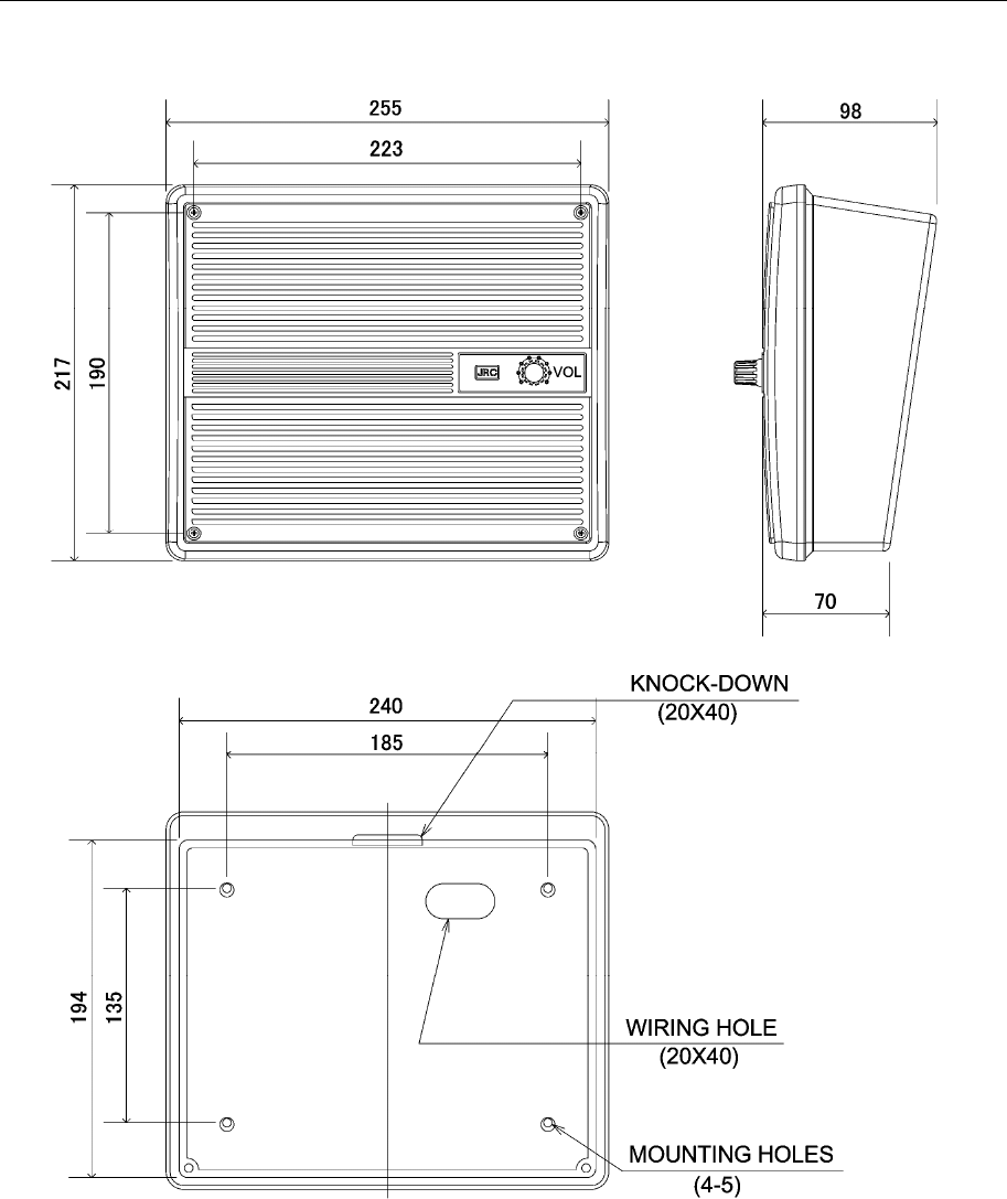
1.4 External dimensions
Below are the external dimensions of each unit.
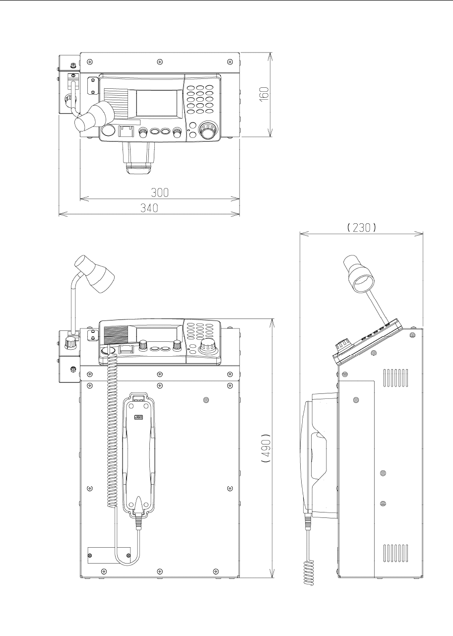
(1) VHF Transceiver (NTE-770S/780D)
(2) VHF Controller (NCM-1770)
Unit: mm
Weight: Approx. 6.3/ 6.9 kg
Unit: mm
Weight: Approx. 1.3 kg
Mounting Hole
(Wiring Hole)
(Wiring Hole)
Mounting Hole
Equipment Overview
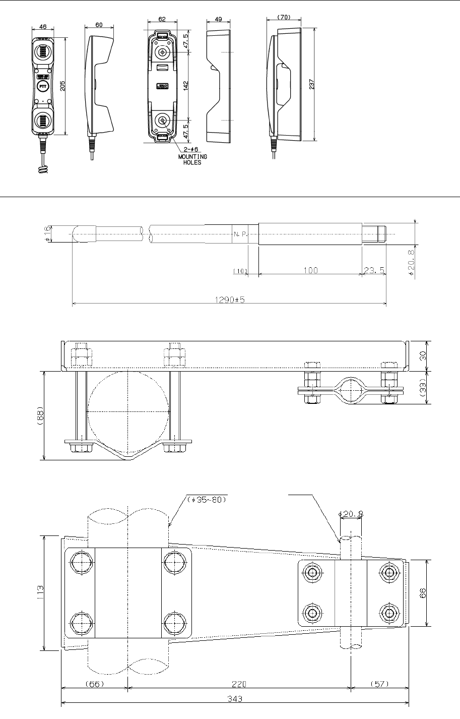
1-5
(3) Handset (NQW-261)
(4) Antenna (7ABJD0004) and Mounting bracket (MPBX41928A)
Unit: mm
Weight: Approx. 0.5 kg
Unit: mm
Weight: Approx. 2.4 kg
Mast Antenna
Equipment Overview
1-6
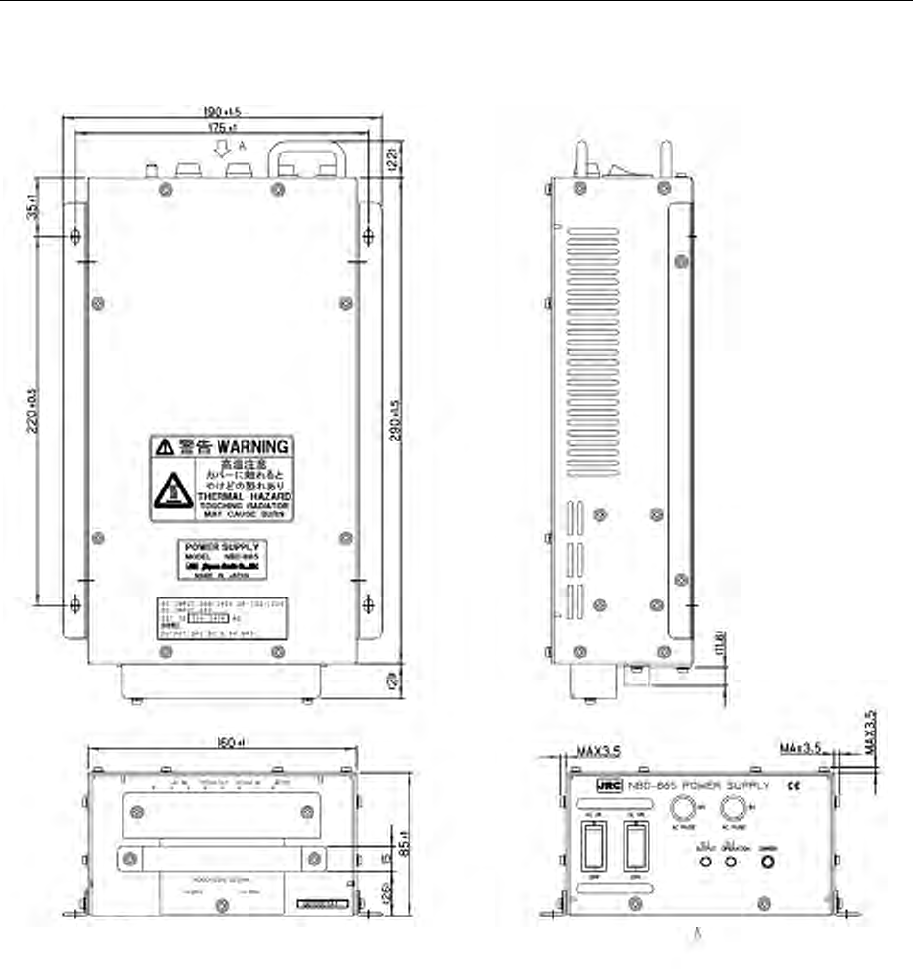
(5) AC/DC Power supply (NBD-865)
Unit: mm
Weight: Approx. 6.1 kg
Equipment Overview
1-7
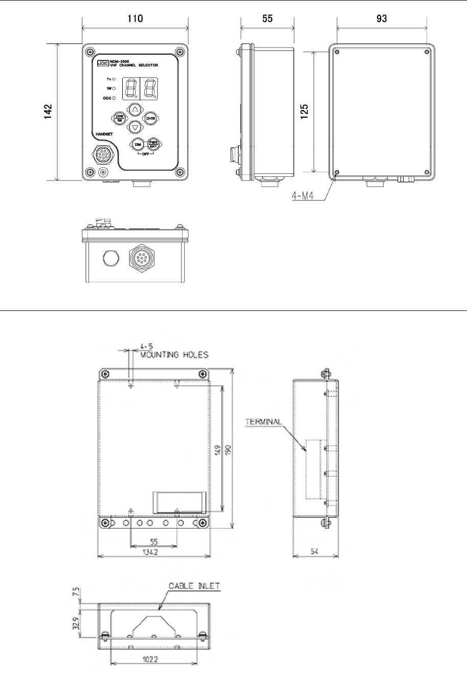
(6) VHF Channel selector (NCM-2000)
(7) Controller connection box (NQD-2770)
Unit: mm
Weight: Approx. 0.6 kg
Unit: mm
Weight: Approx. 0.6 kg
Equipment Overview
1-8
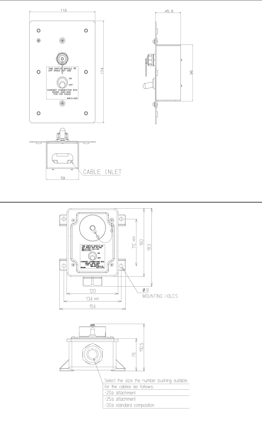
(8) Handset connection box (NQE-1845)
(9) Handset connection box (NQE-1846)
Unit: mm
Weight: Approx. 1.1 kg
Unit: mm
Weight: Approx. 0.5 kg
Equipment Overview
1-9
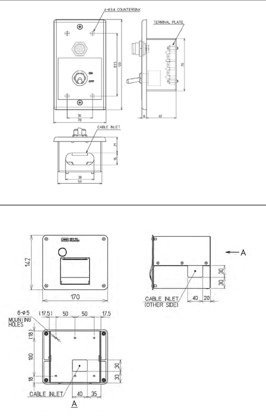
(10) Handset connection box (NQE-1847)
(11) Printer (NKG-91)
● Wall mount type
Unit: mm
Weight: Approx. 0.3 kg
Unit: mm
Weight: Approx. 1.5 kg
Equipment Overview
1-10
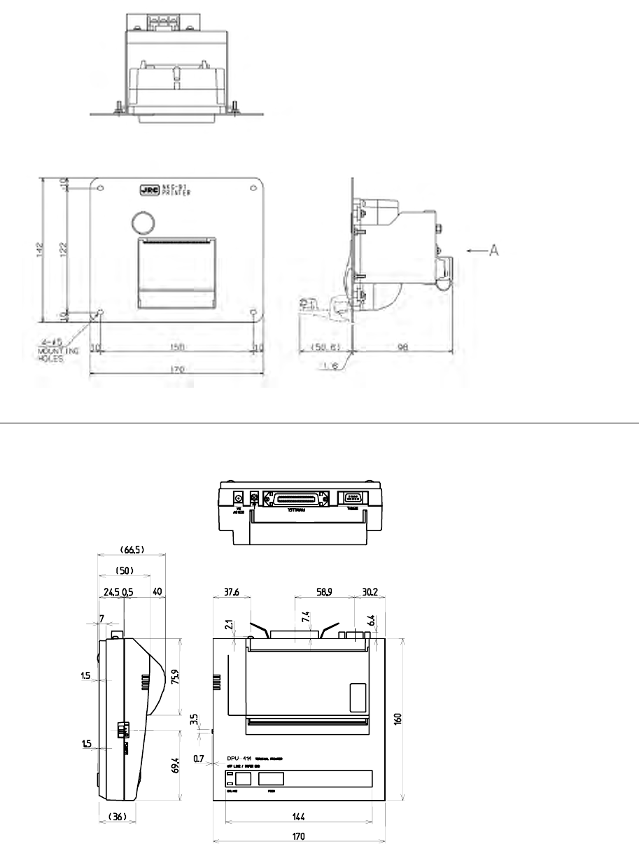
● Flush mount type
(12) Printer (DPU-414)
● Desktop type
Unit: mm
Weight: Approx. 0.6 kg
Unit: mm
Weight: Approx. 0.8 kg
Equipment Overview
1-11
(13) External speaker (NVS-423R)
● Wall mount type
Unit: mm
Weight: Approx. 1.1 kg
Equipment Overview
1-12
(14) Integrated console (JHS-770S-CON/JHS-780D-CON)
Unit: mm
Weight JHS-770S-CON: Approx. 15 kg (with NTE-770S, NCM-1770 and NQW-261)
JHS-780D-CON: Approx. 16 kg (with NTE-780D, NCM-1770 and NQW-261)
Emergency light NZL-1 is optional
Equipment Overview
1-13
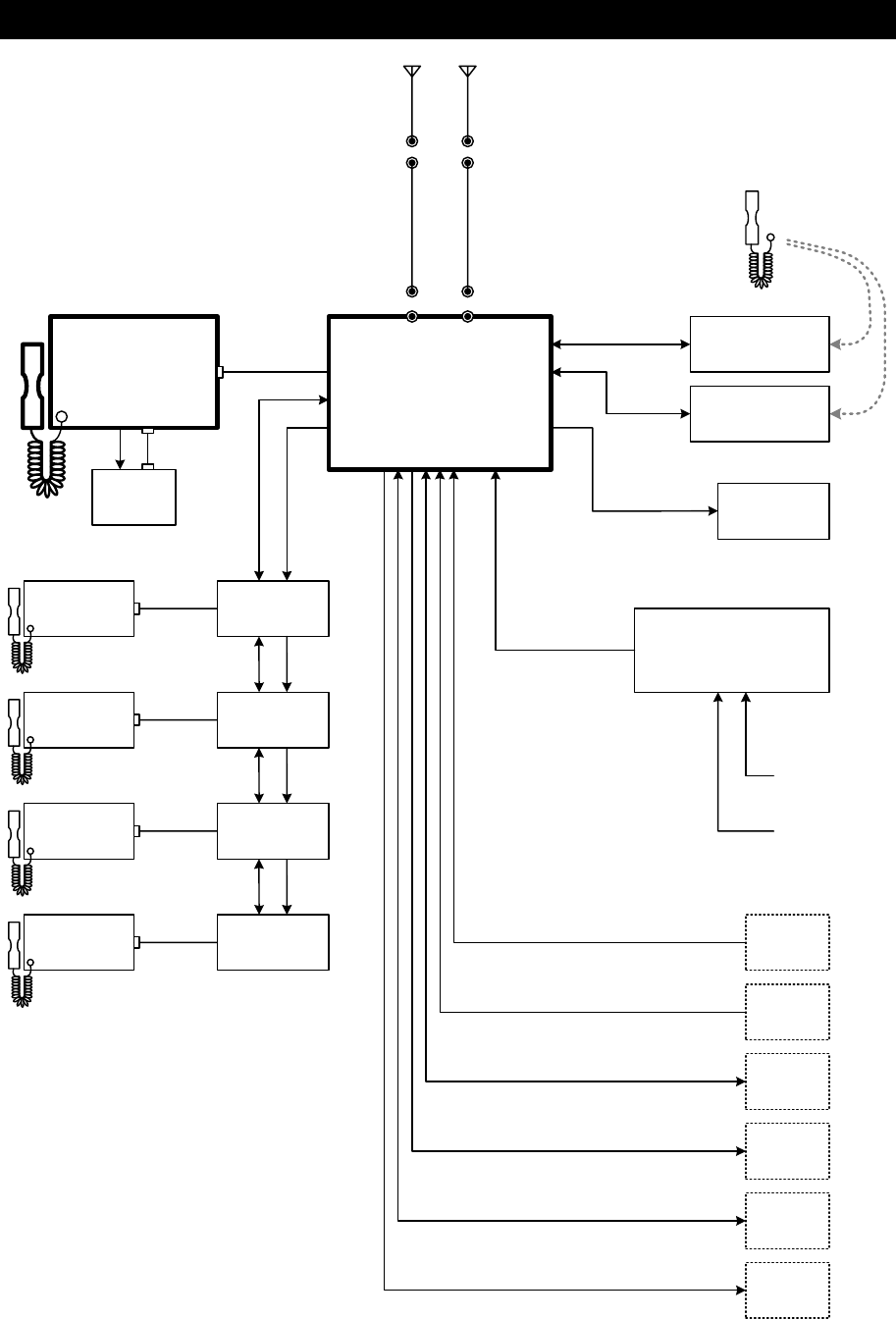
1.5 Block diagram
NCM-1770
VHF Controller
(*1)
NCM-2000
CH selector
(*2)
NCM-2000
CH selector
(*2)
NTE-770S/780D
VHF Transceiver
NBD-865
AC/DC Power supply
100V/220V
AC
50/60Hz 1φ
NCM-1770
VHF Controller
GPS
24V DC
JCY-1800
VDR
AIS
AME
RMS
(VDR)
NCH-
321A
DMC
NQD-2770
Connection box
NQE-1845/1846/1847
Handset
connection box
NVS-423R
External
speaker
DPYCS- 2.5
DPYCS- 2.5
24V DC
RG-10/UY
TTYCS- 1
TTYCS- 4
MPYCS- 4
MPYCS- 7
NKG-91
Printer
MPYCS- 7
DPYC- 4
MPYCS- 7
TTYCS- 1
TTYCS- 4
TTYCS- 1
RG-10/UY
WKR ANT TRX ANT
N-P-10UN-P-10U
N-P-10UN-P-10U
Antenna
7ABJD0004
Antenna
7ABJD0004
7ZCJD0254A
TTYCS- 4 DPYC- 2.5
(24V DC)
NQW-261
Handset
NCM-1770
VHF Controller
(*1)
7ZCJD0299A
(5m)
TTYCS- 4 DPYC- 2.5
(24V DC)
TTYCS- 4 DPYC- 2.5
(24V DC)
TTYCS- 4 DPYC- 2.5
(24V DC)
7ZCJD0299A
(5m)
7ZCJD0299A
(5m)
7ZCJD0299A
(5m)
7ZCJD0299A
(5m)
NQW-261
Handset
NQD-2770
Connection box
NQD-2770
Connection box
NQD-2770
Connection box
*1) Up to two additional
controllers are connectable.
*2) Up to two channel selectors
are connectable. For above
deck installation, NQE-7720
Junction box is usable.
6.5VDC
NQE-1845/1846/1847
Handset
connection box
Equipment Overview
1-14
Names and Functions
2-1
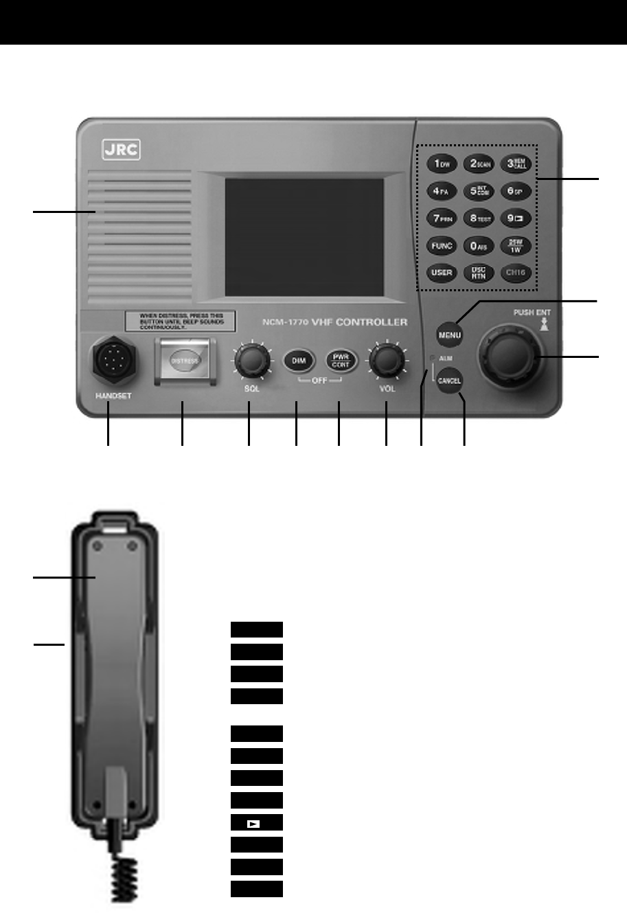
2. NAMES AND FUNCTIONS
2.1 Controller (NCM-1770)
The controller parts and their functions are described below.
1. Internal loud speaker
2. Numeric keypad (10-key) and the each assigned function
In addition to enter numeric values, the function assigned of each keys can
be used to perform the following.
・ 1DW ·········· Displays the dual watch menu
・ 2SCAN
·········· Displays the scan menu.
・ 3 ·········· Displays the memory channel menu.
・ 4PA ·········· Runs the public address mode using an external
speaker.
・ 5 ·········· Displays intercom menu.
・ 6SP ·········· Turns speaker on or off.
・ 7PRN ·········· Prints the DSC messages or some displayed contents.
・ 8TEST ·········· Displays self-diagnosis menu.
・ 9 ·········· Replays the recorded receiving voice.
・ 0AIS ·········· Displays "Other ships list" of the AIS information.
・ FUNC ·········· Temporarily enables function keys mentioned above.
・ ·········· Switches the Tx power between 25W and 1W.
1
2
4
13
3
5 6 7 8 9 10 11 12
14
MEM
CALL
INT
COM
25W
1W

Names and Functions
2-2
・ USER ········User defined key. Register a desired and assignable menu (e.g. frequently using).
・ ········Shortcut key to a DSC routine call menu.
・ CH16 ········Sets the radiotelephone to the priority channel (CH16) quickly.
3. MENU key
Displays menu list.
4. Jog dial
- On the status display, rotating the jog dial will change the channel.
- On a menu or popup screen, rotating the jog dial will move the cursor position or screen contents.
When selecting a button or an item on the screen, rotate the jog dial until the cursor is on it and then
press the jog dial.
Press the jog dial to obtain access rights from other controller.
5. Handset connector
6. DISTRESS key (Under a clear cover with spring)
When in distress, sends a DSC distress call after pressing for 4 seconds.
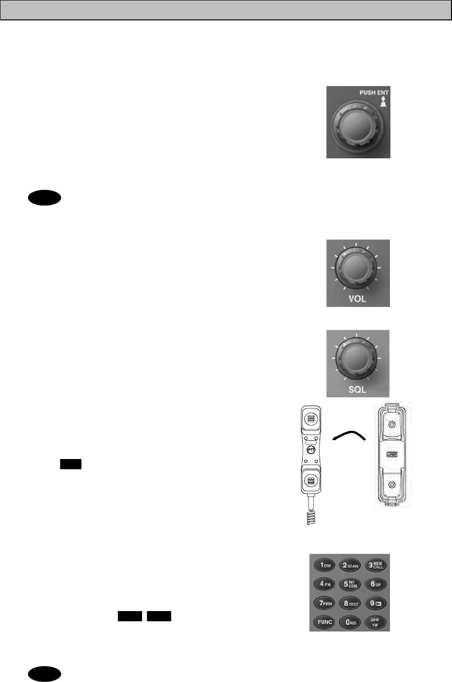
7. SQL (Squelch) control
Adjusts squelch level.
8. DIM (Dimmer) key
Adjusts a dimmer level (Max Æ Typ Æ Min Æ off) of LCD display and key switch. Additionally, used to
power off by pressing it with the key at the same time (a confirmation screen will be displayed).
The adjusted dimmer level is not saved. So when the controller is powered off and on
again, the dimmer level is always set to the Typ (default).
9. PWR/CONT (Power/Contrast) key
Turns on the equipment or makes the controller standby from the sleep mode. And after turned on, this key
is also used to adjust the LCD contrast .
10. VOL (Volume) control
Adjusts built-in loud speaker volume.
11. ALM (Alarm) lamp
Lights up red on any malfunction detected in the equipment or after sending a DSC distress call, or blinks red
on receiving a DSC call. Lights green while the controller is in the sleep mode.
12. CANCEL key
Cancels menus or stops alarms. Additionally, opens the squelch temporally while pressing it on the status
display. (channel monitor function).
13. Handset
When using in radiotelephone mode, press and hold the PTT key to talk.
14. Cradle (for handset)
DSC
RTN
PWR
CONT
Note
Note
PWR
CONT
Names and Functions
2-3
2.2 Main displays
This section describes diligent displays such as the status display, menu screen, and DSC
message receiving screen.
2.2.1 Status display
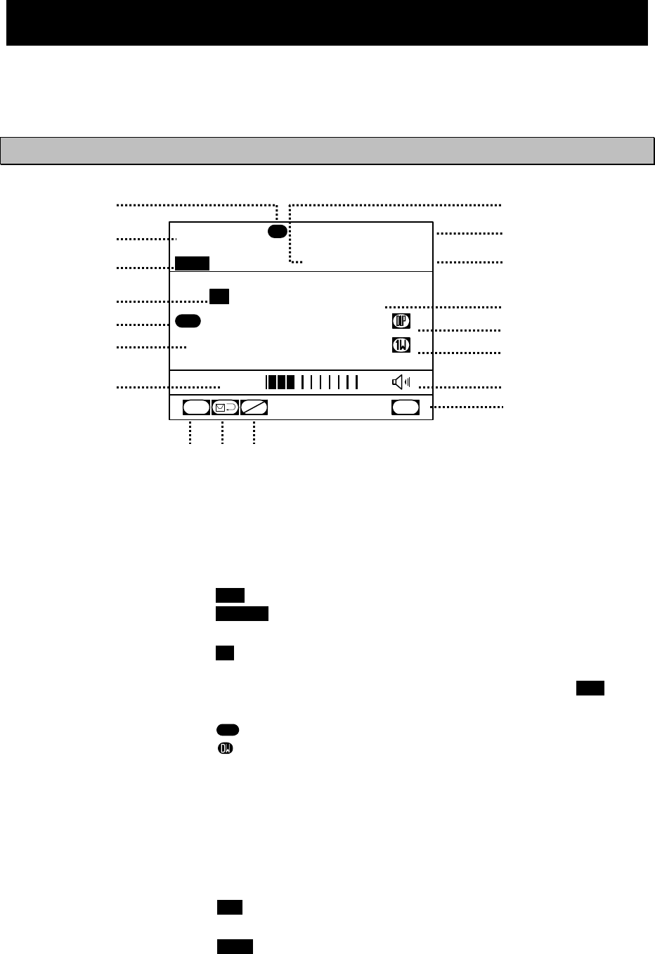
1. Occupied mark indicates when the other
controller has the access rights.
2. Controller name.
3. Transmitting or PLL unlocking mark.
z Transmitting.................... TX
z PLL unlocking.................UNLOCK
4. Indicates the channel category as follows.
z Priority channel, CH70 ....CH
z Private channel ...............CH P0/1/2
z Other channel .................CH
5. On scanning, indicates the current condition.
z.... Scanning....................
z.... Dual Watch ................
6. Indicates the region type of a current channel.
z
[ITU]
....ITU channel
z
[USA]
....USA channel
z
[CAN]
....Canada channel
z
[IWW]
....
European inland waterway channel
7. Indicates the squelch status as follows.
z Closed............................. SQL
z Opened ........................... SQL
z Closed by Preset SQL .... p SQL
z Opened by Preset SQL... p SQL
Also, the actual squelch level is shown on this
level indicator
8. Indicates CH70 watching continuously by the
DSC watchkeeping receiver.
9. Indicates that the DSC is in the automatic
acknowledgement mode.
10. Indicates that the DSC is NOT in the automatic
channel shift mode.
11. Indicates the source of the ship’s position
information as follows.
z External device (e.g. GPS) ..........EXT
z Manual input................................MAN
12. Indicates current time as follows:
z Universal time coordinated ......... UTC
z Local time ................................... LT
13. Indicates own ship’s position.
14. Indicates current channel.
15. Indicates if currently selected a duplex channel
to communicate with a coast station.
16. Indicates Tx power is set to 1W.
17. Indicates the built-in loud speaker's ON/OFF.
Note that in the case of using a duplex
channel for the JHS-780D, when taking a
handset off-hook, the loud speaker will be OFF
automatically.
18. VSWR alarm mark. Indicates when detected
a bad VSWR at transmission.
16&
SCAN
16&
11
13
14
16
17
9 108
6
5
4
3
2
1
12
7
15
Station1 TIME 23:59(UTC)
POS 89゚59'S
EXT 179゚59'W
88
CH
[ITU]
TX
OCC
SQL
CH70
CHSW
SCAN
16&
VSWR
18
Names and Functions
2-4
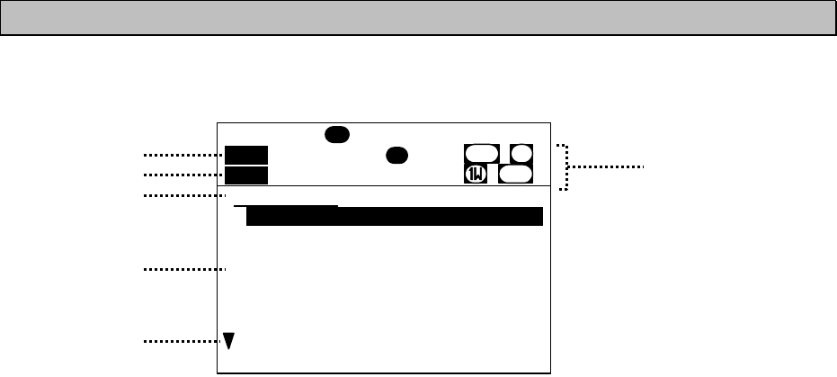
2.2.2 Menu screen
1. Indicates if opened the squelch while performing
one of the 6. Voice function menus.
2. Transmitting mark.
3. Indicates the current menu name.
4. Indicates the menu content. The cursor line or
position is highlighted.
5. Indicates that the menu content is continued
below.
6. Indicates the main radiotelephone information
as with the status display.
Main menu
1.DSC routine call
2.DSC emergency call
3.DSC test call
4.DSC logs
5.AIS information
6.Voice function
7.Channel operation
Station1 TIME 23:59(UTC)
OCC
DW
18
CH70
16
1.DSC routine call
DUP
TX
RX
VSWR
CH [ITU] 6
3
5
4
2
1
Names and Functions
2-5
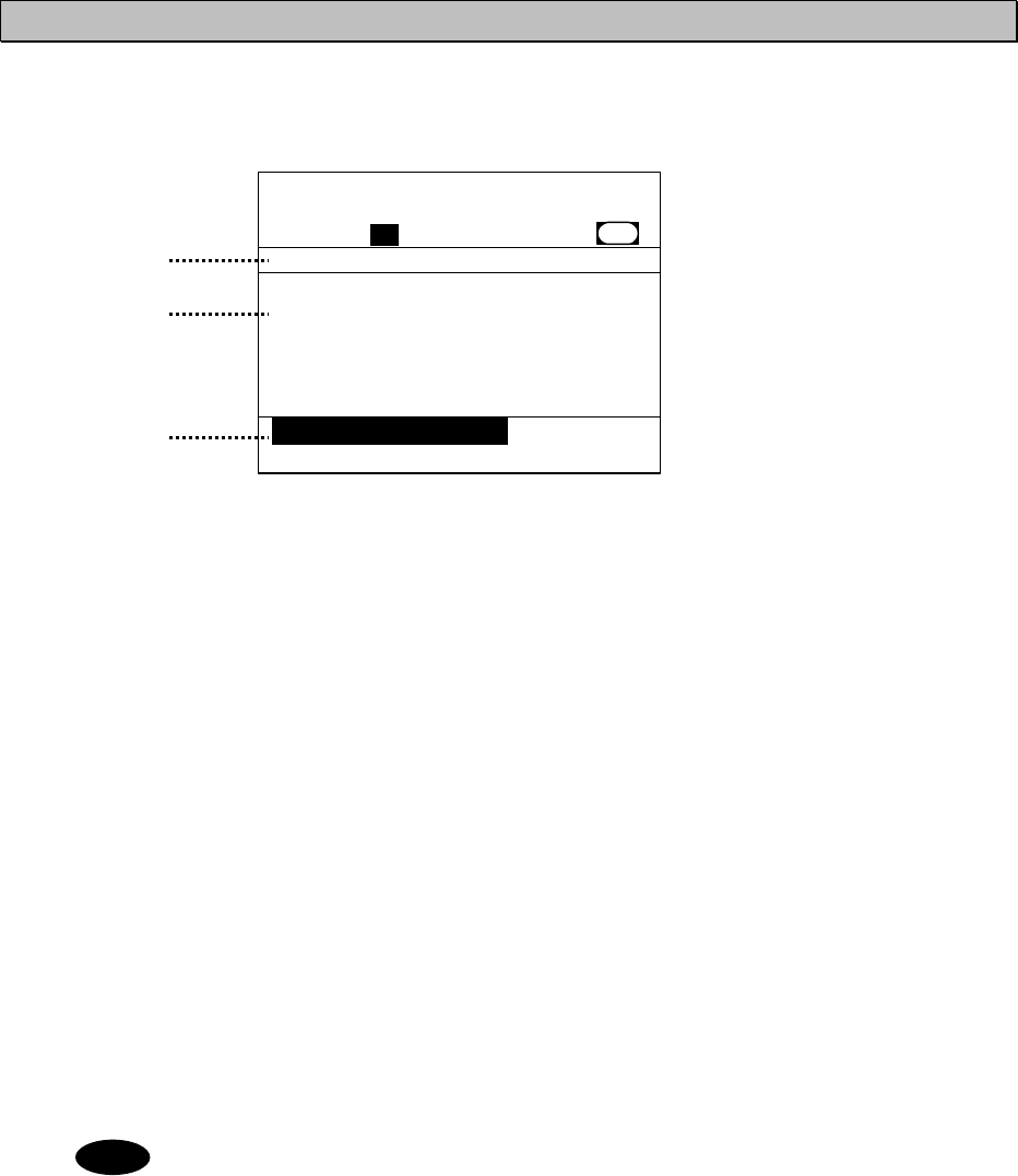
2.2.3 DSC message receiving screen
1. Indicates the received message category.
(Routine, Safety, Urgency, Distress)
2. Indicates the received message. The example
above shows the following contents.
¾ Format : Individual call to own ship
¾ From : The caller's MMSI is 123456789.
¾ Type : Radiotelephone is proposed as a
subsequent communication type.
¾
Work CH
: CH18 proposed as a work channel.
¾ EOS : Requested the acknowledgement.
3. Indicates message handling menu for
received message. The example above
shows the following.
z [OK/Lift handset]
Agreed to the call, and start radiotelephone
communications immediately.
z [New CH]
Agreed to the call except the proposed
channel, and reply to the call with a new
channel proposal.
z [Unable/NACK]
Not agreed to the call, and reply to the call as
"unable to comply" with a reason.
z [Cancel]
Returns to the status display without replying.
・ When selecting [OK/Lift handset] , just lifting a handset enables to start communications
without selecting this item by the jog dial.
・
When selecting [New CH] or [Unable/NACK], an editing screen will appear.
Received routine message
Format :Individual call
From :123456789......
Type :All modes RT...
Work CH :18.............
EOS :ACK RQ.........
Station1 TIME 23:59(UTC)
16
CH70
[OK/Lift handset] [New CH]
[Unable/NACK] [Cancel]
[OK/Lift handset]
CH [ITU]
1
2
3
Note

Installation
3-1
3. INSTALLATION
CAUTION
Leave installation of this equipment to our service center or agents. Special knowledge
on selecting the place where the antenna is to be mounted and setting the ID number
(MMSI) assigned to the ship is required in addition to mounting the equipment.

Operation
4-1
4. OPERATION
This chapter describes basic controller operation, radiotelephone communication, DSC
calling procedures, and other radiotelephone functions.
4.1 Controller operation overview
Basically, the controller is operated with the numeric keypad (10key), the MENU key, and jog dial.
The following is an overview of their operation.
● When two or more controllers are connected, only one controller having the access right can
operate the radiotelephone, except for sending a distress call, changing audio volume, and
changing display conditions. (Unless otherwise mentioned, the instructions below are for the
controller with the access rights.)
● To obtain the access right at a controller without access rights, press the jog dial or take the
handset off-hook under such condition that the controller with the access rights is not in use (such
as taking a handset off-hook, pressing the PTT ON, or operating menu). However note that a
controller installed as a high priority can always obtain the access right if only at the PTT OFF
condition.
● The DISTRESS key is always available even if the controller does not have the access right.
(The DISTRESS key has the highest priority.)
● To verify a prepared DSC message just before sending, provides two types of verification screens:
Simple mode (shows editable information only) and Detail mode (shows every information).
● On the status display, the VHF channel number can be set by using the numeric keys directly or
by rotating the jog dial.
● On the status display, pressing the CANCEL key opens the squelch temporally to listen to the
receiving audio (or noise).
● Placing the handset back on-hook will return the channel to CH16 (factory default value). Also,
the on-hook detection can be disabled at the menu 9.3-5 Hook switch.
● All functions can be accessed using the MENU key, jog dial, and the dedicated keys/controls.
(See the menu tree of the equipment on the next page.)
● Pressing the FUNC (function) key and a numeric key allows rapid access to that function.
● There are two ways to access main menu items. After pressing the MENU key to display the
main menu, use either the jog dial to move the cursor to the desired item and press ENT to select
it, or select the item by pressing the respective numeric key.. (e.g. To select a menu for safety call
to all ships (2.1.1 All Ships), press MENU Æ 2SCAN Æ 1DW Æ 1DW .)
● Any menu can be assigned to the USER key to quickly open it with a single touch of a key.
● Pressing the CANCEL key in any menu moves the display up one level in the hierarchy (or to
the status display). The same results can be achieved by selecting "0. Back" when available
on-screen.. Further, pressing the CANCEL key on an input line will clear the entered data.
● Pressing the MENU key in any menu opens the main menu. Also, pressing the MENU key
while in the main menu returns to the status display.
● If no operations are done for 10 minutes while a menu is open, the screen automatically returns to
the status display.
● Dialog boxes (pop-up screens) are opened when necessary and operations can be done in the
dialog box.
● Screens in the menu tree on the following page indicated by "Printable" can be printed from a
printer connected to the controller by pressing and holding the Func key and then pressing the
7PRN key.
Additionally, if not connected to the controller but the transceiver, the screen or contents will be
printed out from the printer of the transceiver.

Operation
4-2
Menu tree
Main Menu Hierarchical Menu 1 Hierarchical Menu 2 Shortcut Key Note
1. DSC routine call 1.1) Coast station call
1.2) Ship station call DSC RTN
1.3) PSTN call
1.4) Group call
2. DSC emergency call 2.1) Safety call 2.1.1) All ships
2.1.2) Specific station
2.2) Urgency call 2.2.1) All ships
2.2.2) Specific station
2.3) Distress call DISTRESS
2.4) Proxy distress call 2.4.1) All ships
2.4.2) Coast station
3. DSC test call
4. DSC logs 4.1) Received distress (Received distress list) Printable
4.2) Received others (Received others list) Printable
4.3) Transmitted calls (Transmitted calls list) Printable
5.1) Other ships list FUNCÆ0 DSC linking enable
5. AIS information
- Other ships list
- Proximity check
- Proximity range
6.1) Playback FUNCÆ9
6.2) Public address FUNCÆ4
6. Voice function
6.3) Intercom (station list) FUNCÆ5
7. Channel operation
7.1) Scan
- All CH scan
- Memory CH scan
- Select CH scan
FUNCÆ2
7.2) Dual watch FUNCÆ1
7.3) Memory channel 7.3.1) Memory CH list FUNCÆ3 Printable
7.3.2) Registration
7.4) Private channel Printable
7.5) Weather channel Printable
7.6) Region (ITU/USA/CAN/IWW)
7.7) CH SQL setting
- Preset
- All clear
CANCEL
pressing FUNC
8. Maintenance 8.1) Self diagnosis 8.1.1) Transceiver Printable
8.1.2) Controller Printable
8.1.3) Transceiver log Printable
8.1.4) Controller log Printable
8.1.5) DSC loop
FUNCÆ8
Printable
8.2) Alarm information Alarm history Printable
8.3) System information Printable
8.4) Software version Printable
8.5) DSC AF inspection (inspection screen)
9. Setup 9.1) Date & time Clock setting
9.2) POS/TIME
9.3.1) LCD adjustment
9.3.2) Sound FUNCÆ6 (SP)
9.3.3) User key assign
9.3) My controller
- LCD adjustment
- Sound
- User key assign
- Name
- Hook switch
- Off-hook notice
9.4) Contact list 9.4.1) Coast station list Printable
9.4.2) Ship station list Printable
9.4.3) Calling group list Printable
9.4.4) PSTN number list Printable
Printable
9.5) DSC operation
- Automatic ACK
- Automatic CH shift
- Safety/Routine ALM
- Medical/Neutral use
- Expanded MMSI
9.6) AIS function
9.7.1) Controller printer Printable
9.7) Printer property
9.7.2) Transceiver printer Printable
Operation
4-3
4.2 Basic communication procedure
The following describes basic radio communication procedures.
4.2.1 Turning ON the power
CAUTION
Do NOT turn off the power of the equipment when at sea because the SOLAS
Convention requires keeping CH16 watch at all times.
■ Procedure ■
1
1
1.
.
.
Press the key for one second.
The controller and transceiver will start the internal
check. After finished it correctly, the status display
will appears. (The screen at right shows the case
of the JHS-770S Model.)
- When the controller is turned on from
sleep mode, the status display will be
displayed immediately without cheking
the memory.
- If detected errors during the memory
check, displays the message below.
Please inform JRC or our agent of
the error contents.
Message Contents
Detected memory error!
So cleared the area of transceiver memory. Detected a memory error when starting the transceiver.
Detected memory error!
So cleared the area of controller memory. Detected a memory error when starting controller.
Detected this controller's address setting error!
So required initial set after restarting as the
maintenance mode
Detected this controller's address error when starting
the controller.
Detected SIO error!
So required initial set after restarting as the
maintenance mode.
Detected a serial error when starting controller.
Detected MMSI lost!
So concerned functions (DSC/ATIS) no longer
available now.
Unregistered MMSI yet, or lost the MMSI. So required
to install MMSI for DSC/ATIS.
Detected the transceiver's PCB combination error!
So required to replace that incorrect PCB with the
correct one.
Detected the improper transceiver's PCB combination.
PWR
CONT
Note Station1 TIME 23:59(UTC)
POS 89゚59'S
EXT 179゚59'W
16
CH
SQL
CH70
CH
SW
[ITU]
JHS-770S
VHF Radiotelephone
[Self-ID: 987654321]
Controller Version:1.00
Transceiver Version:1.00
JHS-770S
VHF Radiotelephone
[Self-ID: 987654321]
Controller Version:1.00
Transceiver Version:1.00
Operation
4-4
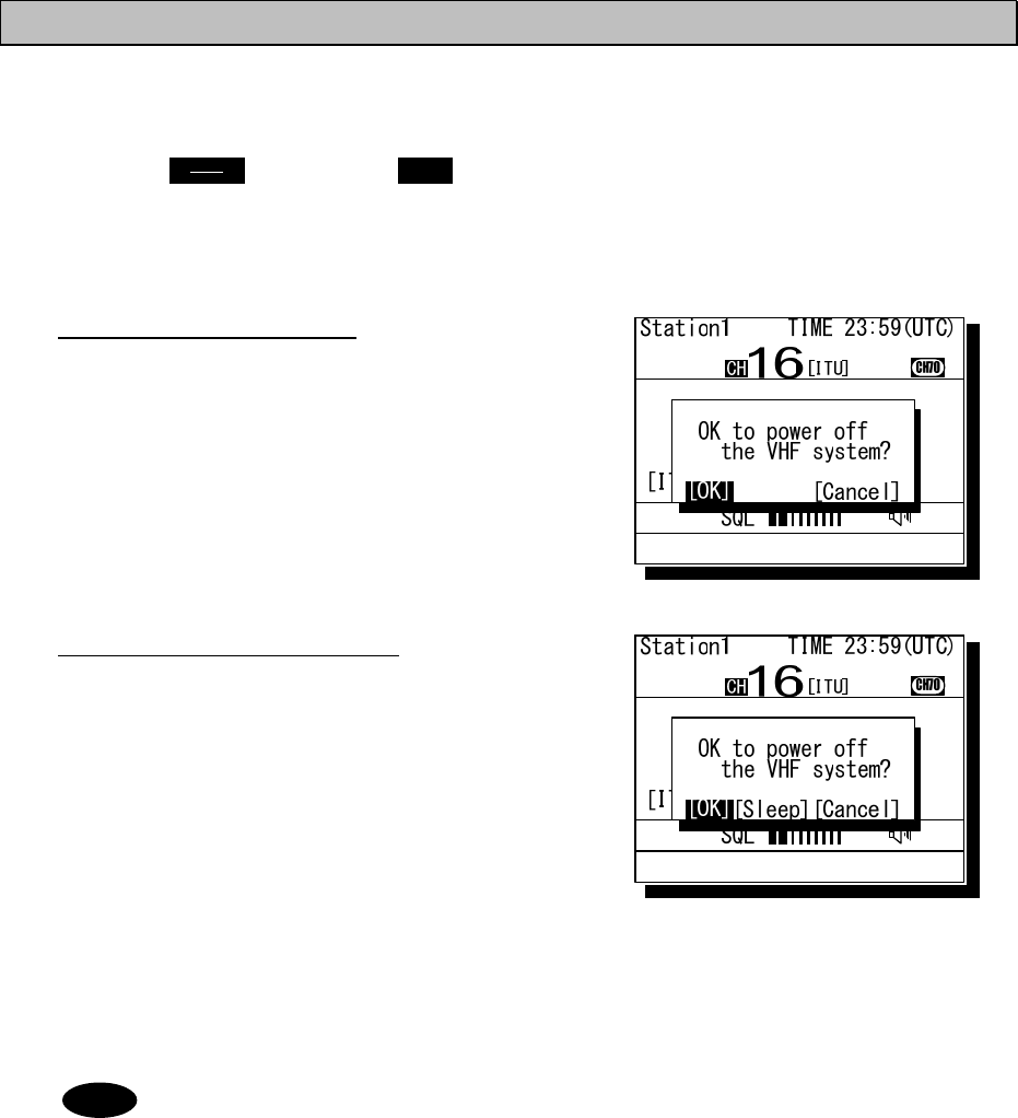
4.2.2 Turning OFF the power
■ Procedure ■
1
1
1.
.
.
Press the key and the DIM key
simultaneously.
After that, the power-off process is activated
according to the controllers' situation.
When using only one controller
Select the desired item below on the displayed popup
screen at right.
・ [OK]: Turns off the power.
・ [Cancel]: Returns to the previous screen.
When using two or more controllers
Select the desired item below on the displayed popup
screen at right.
・ [OK]: Turns off the power.
・ [Sleep]: Sets the controller to sleep mode.
・ [Cancel]: Returns to the previous screen.
In sleep mode, the controller becomes the following conditions.
・ Only the controller is powered off.
・ The ALM lamp turns green to indicate that the controller is in sleep mode,
・ When receiving a distress call, the controller will be automatically turned on and
activate the alarm if the Wake-up setting in an installation menu is ON,.
・ Even if set the controller with access right to the sleep mode, the access right
will not move from the controller.
Note
PWR
CONT
Operation
4-5
4.2.3 Communicating with the radiotelephone
The VHF radiotelephone is operated by means of a handset.
■ Procedure ■
1
1
1.
.
.
When operating on a controller without the access
rights (OCC is displayed), press the jog dial to
obtain the access right.
After obtaining the access right, disappears OCC mark on the
screen and the controller becomes accessible to the VHF
transceiver. Also, just lifting a handset from the cradle
enables to obtain the access right.
When hook-switch setting is invalid, the access right
cannot be acquired by lifting handset from the
cradle.
2
2
2.
.
.
Adjust the volume on the loudspeaker by turning the
volume control.
When receiving no signal, make a noise as a guide by
turning the squelch control counterclockwise until opened.
3
3
3.
.
.
Turn the squelch control to an appropriate position.
Normally, the squelch control would be adjusted to where
rotated the squelch control clockwise one additional tick from
the squelch closing position.
4
4
4.
.
.
Lift the handset from the cradle.
5
5
5.
.
.
Press the PTT key to talk.
¾ The TX mark will appear on the screen to show
the equipment is transmitting. Releasing the PTT
key will return to the receiving condition.
¾ On duplex channels, enabled to listen to the
receiving audio even during the PTT ON.
(In the case of the JHS-780D model.)
6
6
6.
.
.
If necessary, change the channel using the
numeric keypad or jog dial.
Channels can be changed as long as showing the status
display and releasing the PTT key. Additionally, when
entering the channel using the numeric keypad, e.g. in
case of CH18, enter 1DW 8
TEST
.
7
7
7.
.
.
When finished the communication, return the
handset to the cradle.
Placing the handset back on-hook will return the channel to CH16. When hook-switch
setting is invalid, a channel is not changed by returning the handset to the cradle.
Note
Note

Operation
4-6
■ Making a radiotelephone call ■
1
1
1.
.
.
Select CH16 or other agreed channel.
2
2
2.
.
.
Lift the handset from the cradle.
3
3
3.
.
.
Press the PTT key, and make a call as described below.
z Say the calling station name ... Repeat 3 times.
z "this is"
z Say own ship name ... Repeat 3 times.
z "over"
4
4
4.
.
.
Release the PTT key to listen.
5
5
5.
.
.
When answered and agree on a working channel, change to that channel.
6
6
6.
.
.
After checking that no station uses the working channel, begin conversation.
- When transmitting from own station, always press the PTT key while talking.
- On a simplex channel, always say "over" just before releasing the PTT key.
- Always say "out" when terminating communications.
■ Receiving a call on CH16 ■
1
1
1.
.
.
Lift the handset from the cradle.
2
2
2.
.
.
Press the PTT key, and respond to the call as described below.
z Say the caller station name.
z "this is"
z Say own ship name.
3
3
3.
.
.
Propose a channel other than 16 as described below.
z "channel"
z Working channel number
4
4
4.
.
.
Allow the caller station to transmit.
z "over"
5
5
5.
.
.
Release the PTT key, wait a moment, and then switch to the proposed working
channel.
6
6
6.
.
.
After checking that no station uses the working channel, begin conversation.
- When transmitting from own station, always press the PTT key while talking.
- On a simplex channel, always say "over" just before releasing the PTT key.
- Always say "out" when terminating communications.
Note
Note
Operation
4-7
4.2.4 Receiving with scanning
Scanning function enables to watch multiple channels (additional channels) with the priority channel
(CH16). If found receiving signal on the additional channels, the dwell time on that channel will be
longer, but continued to watch the CH16 alternatively. The scan mode can be selected from the
following modes.
・ All CH scan Mode: Scans all channels in the current channel mode.
・ Memory CH scan Mode: Scans all memory channels.
・ Select CH scan Mode: Scans the specified range of channels.
■ Procedure ■
1
1
1.
.
.
Press FUNC Î 2SCAN .
The menu will be displayed as shown at right.
2
2
2.
.
.
Move the cursor to the desired item and
press ENT using the jog dial, or press the
item number by a numeric key directly.
¾ If selected "1. All CH scan" or "2. Memory CH
scan", scanning starts immediately.
¾ If selected "3. Select CH scan", specify the
channel range as described below.
1) To set the start channel (From):
Press ENT and after entering the
channel number, press ENT again.
2) To set the stop channel (To):
Press ENT and after entering the
channel number, press ENT again.
3) To start the scanning:
Select Execute and press ENT. Then
starts the scanning as shown at right.
- Disabled to scan when the channel
region is Inland Waterways (IWW).
- CH70 will be skipped, even if
contained in the scanning range.
3
3
3.
.
.
To terminate scanning, press the CANCEL key.
¾ After terminated, the radiotelephone will be set
on the last additional channel. (The example at
right shows when stopped on CH12.)
¾ Scanning will be also terminated when detected
off-hook, PTT ON, or press the CH16 key or
the DISTRESS key.
- While scanning, the radiotelephone scans CH16 and the additional channels
alternatively in a cycle of 0.14/0.86 seconds.
- If the squelch is opened on the CH16, paused scanning and continues to watch on
7.1)Scan
1.All CH scan
2.Memory CH scan
3.Select CH scan (ITU)
- From : CH
- To : CH
- Execute
0.Back
Note
7.1)Scan
1.All CH scan
2.Memory CH scan
3.Select CH scan (ITU)
- From : CH
- To : CH
- Execute
0.Back
Note
Station1 TIME 23:59(UTC)
POS 89゚59'S
EXT 179゚59'W
10
CH
CH70
CHSW
SCAN
16&
[ITU]
SQL
Station1 TIME 23:59(UTC)
POS 89゚59'S
EXT 179゚59'W
12
CH
CH70
[ITU]
SQL
CHSW
Operation
4-8
the CH16. If squelch is closed again, the scanning will resume 2 seconds later.
- If the squelch is opened on an additional channel, remains on that channel and
CH16 alternatively (in a cycle of 0.14/1.86 seconds). If squelch is then continuously
closed (until the end of the scan cycle), the scanning will resume. Furthermore,
added to the additional channel, if the squelch is also opened on the CH16, paused
scanning and continues to watch on the CH16 as described above.
4.2.5 Receiving with dual watch
Dual watch function enables to watch an additional channel with the priority channel (CH16). If found
receiving signal on the additional channel, the dwell time on that channel will be longer, but continued
to watch the CH16 alternatively.
■ Procedure ■
1
1
1.
.
.
Select an additional channel to be watched
with CH16.
The example at right shows the case of CH10 selected.
2
2
2.
.
.
Press FUNC Î 1DW
The dual watch will start immediately.
Disabled the dual watch either when the
channel region is Inland waterways (IWW)
or when CH70 has been selected.
3
3
3.
.
.
To terminate the dual watch, press
the CANCEL key.
¾ After terminated, the radiotelephone will be
set on the additional channel. (The example at
right shows when stopped on CH10.)
¾ The dual watch will be also terminated when
detected off-hook, PTT ON, or press the CH16
key or the DISTRESS key.
- During the dual watch, the radiotelephone watches CH16 and the additional channel
alternatively in a cycle of 0.14/0.86 seconds.
- If the squelch is opened on the CH16, pauses the dual watch and continues to watch
on the CH16. If squelch is closed again, the dual watch will resume 2 seconds later.
- If the squelch is opened on the additional channel, the dwell time on that channel will
be longer, but continues to watch the CH16 alternatively (in a cycle of 0.14/1.86
seconds). If squelch is then continuously closed (until the end of the dwell time),
the dual watch will resume. Furthermore, added to the additional channel, if the
squelch is also opened on the CH16, pauses the dual watch and continues to watch
on the CH16 as described above.
- This function is also available from the menu 7.2 Dual watch.
Note
Note
Station1 TIME 23:59(UTC)
POS 89゚59'S
EXT 179゚59'W
10
CH
CH70
[ITU]
SQL
CHSW
Station1 TIME 23:59(UTC)
POS 89゚59'S
EXT 179゚59'W
10
CH
CH70
[ITU]
SQL
CHSW
Station1 TIME 23:59(UTC)
POS 89゚59'S
EXT 179゚59'W
10
CH
CH70
16&
[ITU]
SQL
CHSW
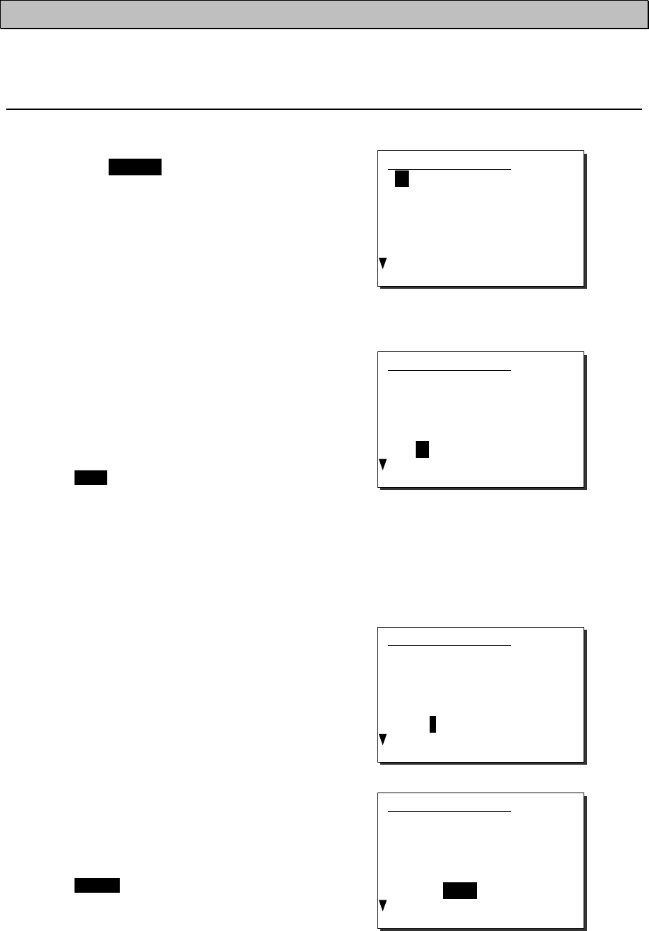
Operation
4-9
4.2.6 Using memory channels
Memory channels are the original channel list. The desired channels (e.g. frequently using channel)
can be registered and used for easy access.
(1) Registering memory channels
■ Procedure ■
1
1
1.
.
.
Press the MENU key and, through
hierarchical menus, select 7.3.2
Registration.
The registration menu of the 7.3 Memory channel
will be displayed as shown at right.
2
2
2.
.
.
Move the cursor to the desired list
number and press ENT using the jog dial,
or press the memory channel number
(two digits) by numeric keys directly.
Then select a channel type.
First, CH will be displayed. Select a channel
type by turning the jog dial (CH → P0 → P1 →
P2 → W → CL), or clear the channel type.
The content of each type is as described below.
・ CH : Region channel
・ P0/1/2 : Private channel (with a hundred digit)
・ W : Weather channel
(CL : Deletes the memory channel)
3
3
3.
.
.
Press ENT after selecting a channel type.
Then input the channel number using the
jog dial or numeric keys.
4
4
4.
.
.
Press ENT after inputting the channel
number. Then select the channel region.
(If selected a private or weather type at step 2,
skip this step.)
First, (ITU) will be displayed. Select a
channel region by turning the jog dial (ITU →
USA → CAN → IWW).
7.3.2)Registration
01.CH71(ITU)
02.CH60(CAN)
03.CH05(ITU)
04.P001
05.P002
06.
07.
7.3.2)Registration
01.CH71(ITU)
02.CH60(CAN)
03.CH05(ITU)
04.P001
05.P002
06.CH
07.
7.3.2)Registration
01.CH71(ITU)
02.CH60(CAN)
03.CH05(ITU)
04.P001
05.P002
06.CH01
07.
7.3.2)Registration
01.CH71(ITU)
02.CH60(CAN)
03.CH05(ITU)
04.P001
05.P002
06.CH01(ITU)
07.
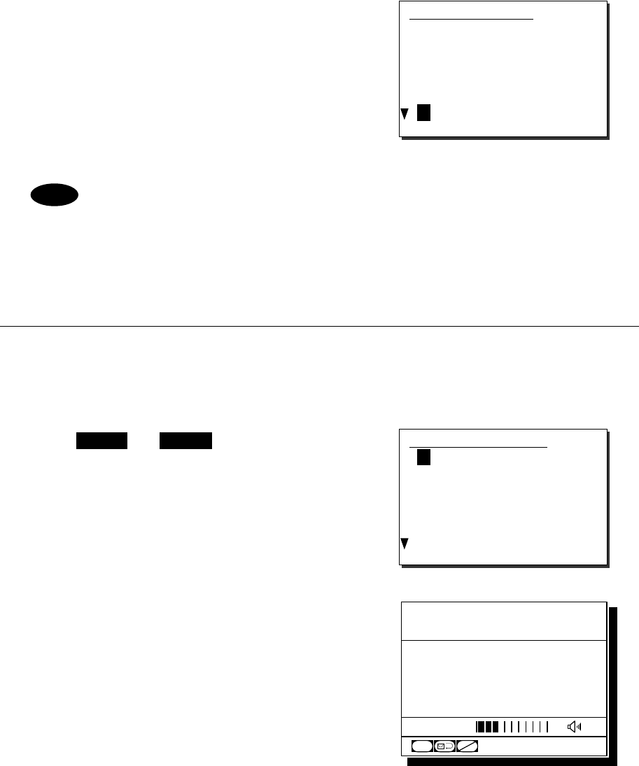
Operation
4-10
5
5
5.
.
.
Press ENT after finished the steps above.
Then saved the memory channel number
and the cursor moves to the next number.
When registering other channels or revising
existing lines, repeat the steps 2 - 5 above.
- The above procedures are for registering a channel in an empty line. However
editing an existing memory channels is as well.
- To delete a registered memory channel, select CL at step 2 of the procedure above.
(2) Communicating on a memory channel
Memory channels will be available e.g. when setting a working channel for subsequent communication
after initial contact on CH16.
■ Procedure ■
1
1
1.
.
.
Press FUNC Î 3 .
The 7.3.1 Memory CH list will be displayed as
shown at right.
2
2
2.
.
.
Move the cursor to the desired list number
and press ENT using the jog dial, or press
the memory channel number (two digits) by
numeric keys directly.
In this example, if selected the memory channel
number 05, CH P002 will be set.
Note
7.3.2)Registration
01.CH71(ITU)
02.CH60(CAN)
03.CH05(ITU)
04.P001
05.P002
06.CH01(ITU)
07.
7.3.1)Memory CH list
01.CH71(ITU)
02.CH60(CAN)
03.CH05(ITU)
04.P001
05.P002
06.CH01(ITU)
07.
MEM
CALL
Station1 TIME 23:59(UTC)
POS 89゚59'S
EXT 179゚59'W
02
CH P0
CH70
CHSW
SQL
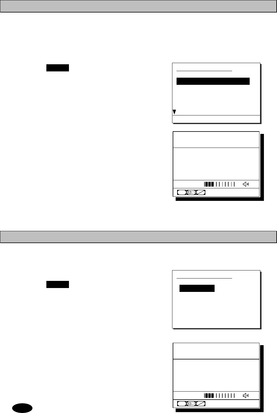
Operation
4-11
4.2.7 Communicating on a private channel
Private channels for assigned frequencies of fishing ship or other specially assigned frequencies are
registered at the installation of equipment. Up to 200 channels are available for radiotelephone
communications. (If required to add channels after installation, please contact JRC or our agent.)
■ Procedure ■
1
1
1.
.
.
Press the MENU key, and through
hierarchical menus, select the 7.4 Private
channel.
Indicates the information of the highlighted line
by the cursor on the bottom of the screen.
2
2
2.
.
.
Move the cursor to the desired channel
number and press ENT using the jog dial,
or press the private channel number (three
digits) by numeric keys directly.
In this example, if selected the CH P200, the
screen will become as shown at right.
4.2.8 Receiving a weather channel
Weather channels are available to receive weather information on the North American coast.
■ Procedure ■
1
1
1.
.
.
Press the MENU key, and through
hierarchical menus, select the 7.5
Weather channel.
2
2
2.
.
.
Move the cursor to the desired line and
press ENT using the jog dial, or press a
numeric key directly.
When selected the channel 8, the screen will
become as shown at right.
Disabled to transmit on weather channels.
7.5)Weather channel
1.162.550MHz 6.162.500MHz
2.162.400MHz 7.162.525MHz
3.162.475MHz 8.161.650MHz
4.162.425MHz 9.161.775MHz
5.162.450MHz 0.163.275MHz
Note
7.4)Private channel
TX RX
1:156.0000 160.6000MHz
2:156.0250 160.6250MHz
3:156.0500 160.6500MHz
4:156.0750 160.6750MHz
5:156.1000 160.7000MHz
6:156.1250 160.7250MHz
Sim
p,
25W
,
Scramble ON
Station1 TIME 23:59(UTC)
POS 89゚59'S
EXT 179゚59'W
00
CH P2
CH70
CHSW
SQL
Station1 TIME 23:59(UTC)
POS 89゚59'S
EXT 179゚59'W
W
8
CH
CH70
CHSW
SQL
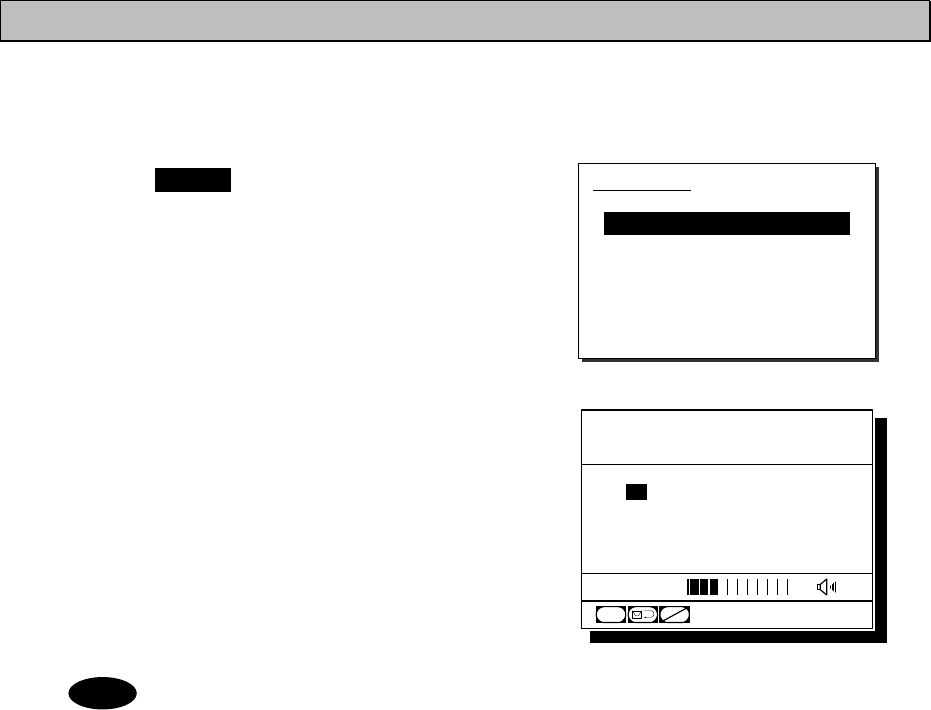
Operation
4-12
4.2.9 Changing the channel region
This menu sets the channel region to ITU, USA, Canada, or Inland Waterway.
■ Procedure ■
1
1
1.
.
.
Press the MENU key, and through
hierarchical menus, select the 7.6 Region.
2
2
2.
.
.
Move the cursor to the desired line and
press ENT using the jog dial, or press a
numeric key directly.
When selected the USA channel, the screen will
become as shown at right.
When set to the Inland Waterway (IWW), changed a few functions as follows.
- Enabled the ATIS function automatically and sends the ATIS code over the
voice channel when releasing the PTT key. Also, if pressed the PTT key
continuously, sends the ATIS code every five minutes automatically.
- Disabled the scan or dual watch functions.
- When operating the DSC menus, a popup screen will be displayed to notice that
the DSC usage is not allowed on Inland Waterways.
7.6)Region
1.ITU channel [ITU]
2.USA channel [USA]
3.Canada channel [CAN]
4.Inland channel [IWW]
0.Back
Note
Station1 TIME 23:59(UTC)
POS 89゚59'S
EXT 179゚59'W
CH
CH70
16
[USA]
SQL
CHSW
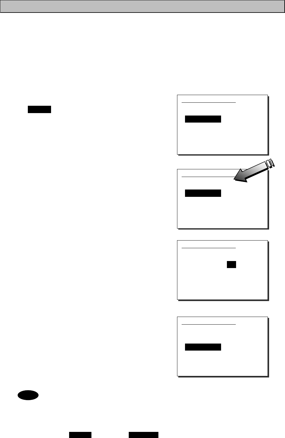
Operation
4-13
4.2.10 Squelch settings of each channel (preset squelch)
The adjusted squelch value can be stored with respect to each channel as a preset squelch. The
handling of the preset squelch will be as follows.
・ If stored the squelch value, the preset squelch will be always set just after the channel selection.
・ While the preset squelch has been set, "p SQL" will be indicated on the status display.
・ If turned the SQL control after setting the preset channel, the preset value will be canceled
immediately and the SQL control will be available.
・ The preset squelch value can be cleared with respect to each channel or each channel region.
■ Procedure ■
1
1
1.
.
.
After selecting the desired channel, press
the MENU key and through hierarchical
menus, select the 7.7 CH SQL setting.
2
2
2.
.
.
Turn the SQL control to the appropriate
position.
The SQL value as shown at right will be
changed corresponding to the SQL control
position.
3
3
3.
.
.
Press ENT.
The cursor will move to the right.
4
4
4.
.
.
To complete the squelch setting for the
channel, select "Set" and press ENT.
- To clear the preset squelch values with respect to each channel, after selecting the
channel, select Erase and press ENT at the step 3 above.
- To clear the preset squelch values with respect to each channel region, in the
condition of that channel region, move the cursor to the 2. All clear and press ENT.
- The above operation is also available on a popup menu displayed when pressed both
of the FUNC key and the CANCEL key simultaneously on the status display.
7.7)CH SQL setting
SQL value [052]
1.Preset : Set
2.All clear
0.Back
7.7)CH SQL setting
SQL value [041]
1.Preset : Set
2.All clear
0.Back
7.7)CH SQL setting
SQL value [025]
1.Preset : Set
2.All clear
0.Back
7.7)CH SQL setting
SQL value [025]
1.Preset : Set
2.All clear
0.Back
Note
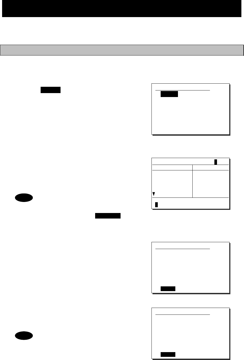
Operation
4-14
4.3 Basic DSC operations
When calling stations, the DSC is also available for a routine/ safety/ urgency or a distress call in
addition to the calling by radiotelephone described above. This section describes the procedures for
basic DSC routine calls and for the AIS-linked DSC calls.
4.3.1 Routine calls to a coast station
A DSC call to a coast station is initiated as follows.
■ Procedure ■
1
1
1.
.
.
Press the MENU key, and through
hierarchical menus, select the 1.1 Coast
station call.
The address inputting screen will be displayed.
If entered previously, the address will be
appeared as a default value.
2
2
2.
.
.
Press ENT to display the alphabetically
sorted coast station list. After selecting the
initial letter and pressing ENT, select the
desired coast station with the jog dial.
- This list can be registered in the
menu 9.4.1 Coast station list.
- When inputting the MMSI
manually, press the CANCEL
key to return to the previous
screen and input it using the
numeric keypad.
3
3
3.
.
.
After inputting the address, press ENT.
Confirm the address.
4
4
4.
.
.
If the address is correct, press ENT.
The sending confirmation screen will appear.
The controller displays by default only
the edited information in the call setup
as shown at right.
1.1)Coast station call
Address :[00 ]
[
OK
]
[
Cancel
]
1.1)Coast station call
Address :[001234567]
[
OK
]
[
Cancel
]
1.1)Coast station call
Address :001234567
[
Call
]
[
Cancel
]
Note
Note
Coast station list [A]
NAME MMSI
Argentina
Australia
Azerbaijan
Bolivia
Bangladesh
001234567
002222222
003333333
004444444
005555555
Select the initial of the name.
ABCDEFGHIJKLMNOP
Q
RSTUVWXYZ
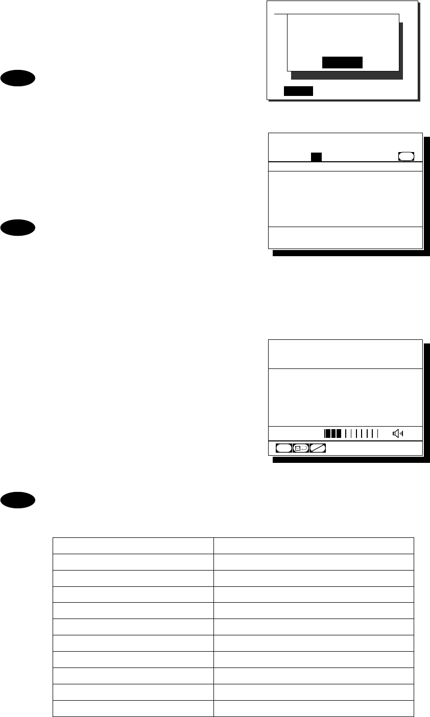
Operation
4-15
5
5
5.
.
.
Press ENT to transmit the call.
After completed the transmission, the popup
screen shown at right will be displayed to wait
the acknowledgement.
If received no response for 5 minutes,
the screen will return to the step 3
mentioned above.
6
6
6.
.
.
When received the acknowledgement, the
screen shows the message with the alarm
for 3 sec. Then changes to the working
channel proposed by the coast station
automatically.
- If 9.5.2 Automatic CH shift is OFF,
lifting the handset or pressing ENT
is required to set the proposed
working channel.
- If an improper channel is proposed,
resend the call containing a new
channel via the specified new
channel proposal form screen.
7
7
7.
.
.
The coast station call will be completed
after displayed the working channel as
shown at right.
Start communications using the handset.
¾ The example at right shows when proposed
CH12 as a working channel.
¾ When completed the communications, return
the handset to the cradle.
If the coast station is unable to comply with the call, own station (caller) may receive
one of the following responses may be received. In these cases, if possible according
to the message, wait and retry the calling again later.
Message Content
No reason No reason.
Congestion The marine exchange center is congested.
Busy Busy.
Queue The call has been queued.
Barred The station is closed.
No operator Existing no operator.
Temp no oper The operator is temporarily away.
EQP disabled The equipment has been disabled.
Unable channel The proposed channel cannot be used.
Unable mode The proposed mode cannot be used.
Note
1.1)Coast station call
Address :[001234567]
[
Call
]
[
Cancel
]
Waiting for
Acknowledgement.
[Cancel]
Note
Note
Station1 TIME 23:59(UTC)
POS 89゚59'S
EXT 179゚59'W
12
CH
CH70
[ITU]
SQL
CHSW
Received routine message
Format :Individual ACK
From :001234567......
Type :All modes RT...
Work CH :12.............
EOS :ACK BQ.........
Station1 TIME 23:59(UTC)
16
CH70
Press CANCEL to silence alarm.
CH [ITU]
Operation
4-16
4.3.2 Routine calls to a ship station
A DSC call to a ship station is initiated as follows. This procedure is similar to that of menu 1.1 Coast
station call but also needed to input a working channel.
■ Procedure ■
1
1
1.
.
.
Press the key.
The menu shown at right will be displayed.
If entered previously, the address will be
appeared as a default value.
2
2
2.
.
.
Press ENT to display the alphabetically
sorted ship station list. After selecting the
initial letter and pressing ENT, select the
desired ship station with the jog dial.
- The list can be registered in the
menu 9.4.2 Ship station list.
- When inputting the MMSI manually,
press the CANCEL key to return
to the previous screen and input it
using the numeric keypad.
3
3
3.
.
.
Press ENT.
The cursor will move to the Work CH.
4
4
4.
.
.
Press ENT and input the working channel.
- The free channel will be searched
and displayed automatically.
- If required, input another channel
manually using the CANCEL
key, the jog dial or the numeric
keys.
- If there is no free channel, a blank
will be shown as a search result.
5
5
5.
.
.
Press ENT.
Confirm the entered contents.
1.2)Ship station call
Address :[ ]
Work CH :[ ]
[
OK
]
[
Cancel
]
1.2)Ship station call
Address :[123456789]
Work CH :[ ]
[
OK
]
[
Cancel
]
1.2)Ship station call
Address :[123456789]
Work CH :[06]
[
OK
]
[
Cancel
]
Note
1.2)Ship station call
Address :[123456789]
Work CH :[06]
[
OK
]
[
Cancel
]
DSC
RTN
Ship station list [A]
NAME MMSI
AAA ocean
ABB ocean
ACC ocean
ABC ocean
BBB ocean
123456789
222222222
333333333
444444444
555555555
Select the initial of the name.
ABCDEFGHIJKLMNOP
Q
RSTUVWXYZ
Note
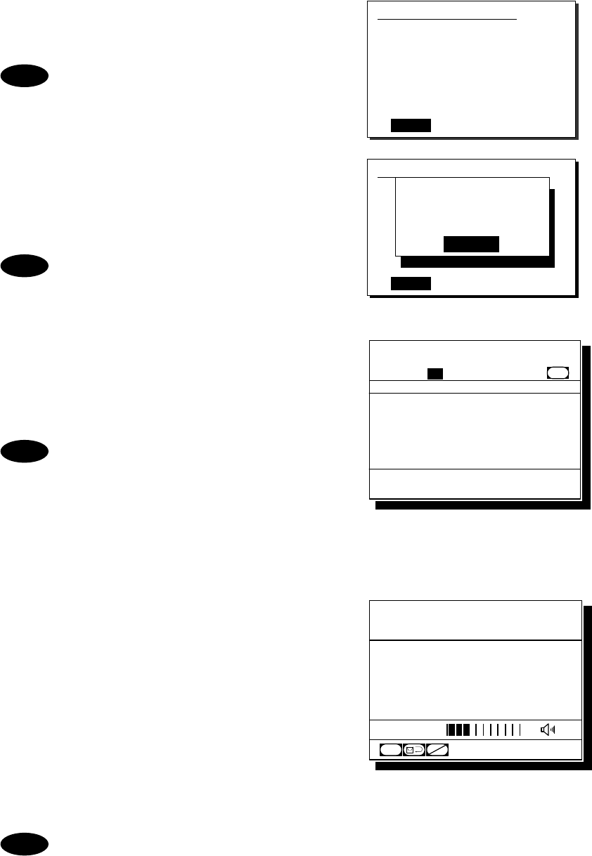
Operation
4-17
6
6
6.
.
.
If the contents are correct, press ENT.
The sending confirmation screen will appear.
The controller displays by default only
the edited information in the call setup
as shown at right.
7
7
7.
.
.
Press ENT to transmit the call.
After completed the transmission, the popup
screen shown at right will be displayed to wait
the acknowledgement.
If received no response for 5 minutes,
the screen will return to the step 5
mentioned above.
8
8
8.
.
.
When received the acknowledgement, the
screen shows the message with the alarm
for 3 sec. Then changes to the proposed
working channel automatically.
- If 9.5.2 Automatic CH shift is OFF,
lifting the handset or pressing ENT
is required to set the proposed
working channel.
- If an improper channel is proposed,
resend the call containing a new
channel via the specified new
channel proposal form screen.
9
9
9.
.
.
The ship station call will be completed
after displayed the working channel as
shown at right.
Start communications using the handset.
¾ The example at right shows when proposed
CH06 as a working channel.
¾ When completed the communications,
return the handset to the cradle.
- If the ship station is unable to comply with the call, as with coast stations, own
station (caller) may receive a negative acknowledgement mentioned above section.
In this case, if possible according to the message, wait and retry the calling again
later.
- When calling group ships to broadcast, use the menu 1.4 Group call as with this
procedure except for steps 7 and 8.
Note
1.2)Ship station call
Address :123456789
Work CH :06
[
Call
]
[
Cancel
]
Note
1.2)Ship station call
Address :123456789
Work CH :71
[
Call
]
[
Cancel
]
Waiting for
Acknowledgement.
[Cancel]
Note
Note
Station1 TIME 23:59(UTC)
POS 89゚59'S
EXT 179゚59'W
06
CH
CH70
[ITU]
SQL
CHSW
Received routine message
Format :Individual ACK
From :123456789......
Type :All modes RT...
Work CH :06.............
EOS :ACK BQ.........
Station1 TIME 23:59(UTC)
16
CH70
Press CANCEL to silence alarm.
CH [ITU]
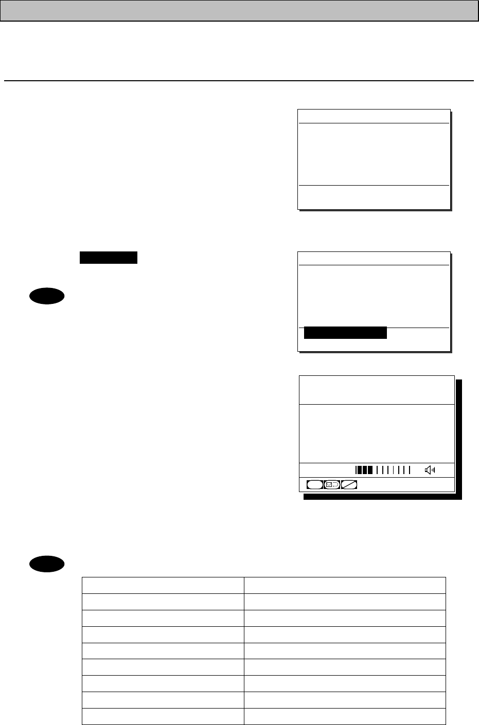
Operation
4-18
4.3.3 Receiving a routine call
When receiving a DSC call from a coast or ship station, the message will be displayed immediately on
the screen. After that, perform the following procedures as appropriate.
(1) Receiving an individual call (type: radiotelephone)
■ Procedure ■
1
1
1.
.
.
The screen at right will be displayed, and
the alarm will sound.
This example message contains the following
information.
- Format: Individual call
- Caller's MMSI: 111222333
- Type: All modes radiotelephone
- Work channel: CH12
- EOS: ACK is requested.
2
2
2.
.
.
Press the CANCEL key to stop the
alarm and display the screen at right.
This step is omissible.
3
3
3.
.
.
If possible to communicate immediately,
lift the handset from the cradle and start
the communications.
¾ In this example case, enabled to select the
response from below with the jog dial.
・OK/Lift handset: Starts communications
immediately.
・New CH: Proposes a new channel.
・Unable/NACK: Sends "Unable to comply" message with that reason.
・Cancel: Returns to the status display without handling this message.
¾ When completed the communications, return the handset to the cradle.
When selected "Unable/NACK", also select a reason from the list given below.
Message Content
No reason No reason.
Busy Busy.
Barred The station is closed.
No operator Existing no operator.
Temp no oper The operator is temporarily away.
EQP disabled The equipment has been disabled.
Unable channel The proposed channel cannot be used.
Unable mode The proposed mode cannot be used.
Received routine message
Format :Individual call
From :111222333
Type :All modes RT
Work CH :12
EOS :ACK RQ
[OK/Lift handset] [New CH]
[Unable/NACK] [Cancel]
Received routine message
Format :Individual call
From :111222333
Type :All modes RT
Work CH :12
EOS :ACK RQ
Press CANCEL to silence alarm.
Note
Note
Station1 TIME 23:59(UTC)
POS 89゚59'S
EXT 179゚59'W
12
CH
CH70
[ITU]
SQL
CHSW
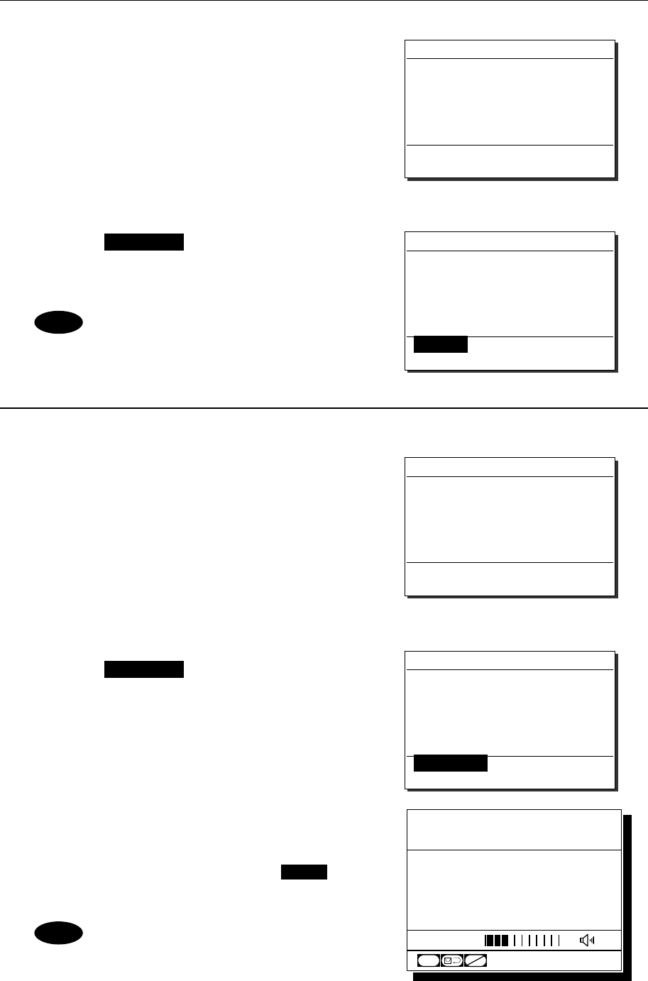
Operation
4-19
(2) Receiving an individual call (type: polling)
■ Procedure ■
1
1
1.
.
.
The screen at right will be displayed, and
the alarm will sound.
This example message contains the following
information.
- Format: Individual call
- Caller’s MMSI: 001234567
- Type: Polling
- EOS: ACK is requested.
2
2
2.
.
.
Press the CANCEL key to stop the alarm
and display the screen at right. If possible
to respond immediately, press ENT.
If Automatic ACK is ON, the
acknowledgement will be sent
automatically without notice.
(3) Receiving a group call
■ Procedure ■
1
1
1.
.
.
The screen at right will be displayed, and
the alarm will sound.
The example message contains the following
information.
- Format: Group call
- Caller’s MMSI: 111222333
- Type: All modes radiotelephone
- Work Channel: CH12
- EOS: EOS
2
2
2.
.
.
Press the CANCEL key to stop the
alarm and display the screen at right.
3
3
3.
.
.
If possible to listen to the broadcast, press
ENT, and set to the working channel.
When finished the broadcast, press the CH16
key to return to the status display.
If Automatic CH shift is ON, the working
channel will be changed automatically
and the above step 2 and 3 are omitted.
Received routine message
Format :Individual call
From :111222333
Type :All modes RT
Work CH :12
EOS :EOS
[OK/Listen] [Cancel]
Received routine message
Format :Group call
From :111222333
Type :All modes RT
Work CH :12
EOS :EOS
Press CANCEL to silence alarm.
Received routine message
Format :Individual call
From :001234567
Type :Polling
EOS :ACK RQ
[OK/ACK] [Cancel]
Received routine message
Format :Individual call
From :001234567
Type :Polling
EOS :ACK RQ
Press CANCEL to silence alarm.
Note
Note
Station1 TIME 23:59(UTC)
POS 89゚59'S
EXT 179゚59'W
12
CH
CH70
[ITU]
SQL
CHSW
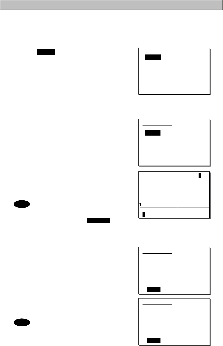
Operation
4-20
4.3.4 Communicating with a PSTN subscriber
The semi/auto mode is available to connect with a public telephone network (PSTN) via a coast station.
(1) Make a call to a PSTN subscriber
■ Procedure ■
1
1
1.
.
.
Press the MENU key, and through
hierarchical menus, select the menu 1.3
PSTN call.
The menu shown at right will be displayed.
If entered previously, the address and the TEL
number will be appeared as a default value.
Additionally, in the case of JHS-780D, "Type"
line will be shown to select the mode from
"All modes RT" or "Duplex RT".
2
2
2.
.
.
As with the routine calls mentioned above,
enter the address and press ENT.
The cursor will move to the TEL No.
3
3
3.
.
.
Press ENT to display the alphabetically
sorted TEL number list. After selecting
the initial letter and pressing ENT, select
the recipient of the call with the jog dial.
- This list can be registered in the
menu 9.4.4 PSTN number list.
- When inputting the TEL number
manually, press the CANCEL
key to return to the previous
screen, and input it using the
numeric keypad.
4
4
4.
.
.
Press ENT.
Confirm the entered contents.
5
5
5.
.
.
If the contents are correct, press ENT.
The sending confirmation screen will appear.
The controller displays by default only
the edited information in the call setup
as shown at right.
1.3)PSTN call
Address:[00 ]
TEL No.:[ ]
[
OK
]
[
Cancel
]
Note
1.3)PSTN call
Address:[001234567]
TEL No.:[ ]
[ OK ] [Cancel]
1.3)PSTN call
Address :001234567
TEL No. :1122334455667788
[Call] [Cancel]
1.3)PSTN call
Address:[001234567]
TEL No.:[1122334455667788]
[ OK ] [Cancel]
Note
TEL number list [A]
NAME Heading num
Alex 11223344556
Andy
Arnold
Blanco
Bob
00125412345
01011448851
00102875521
001149586
Select the initial of the name.
ABCDEFGHIJKLMNOPQRSTUVWXYZ
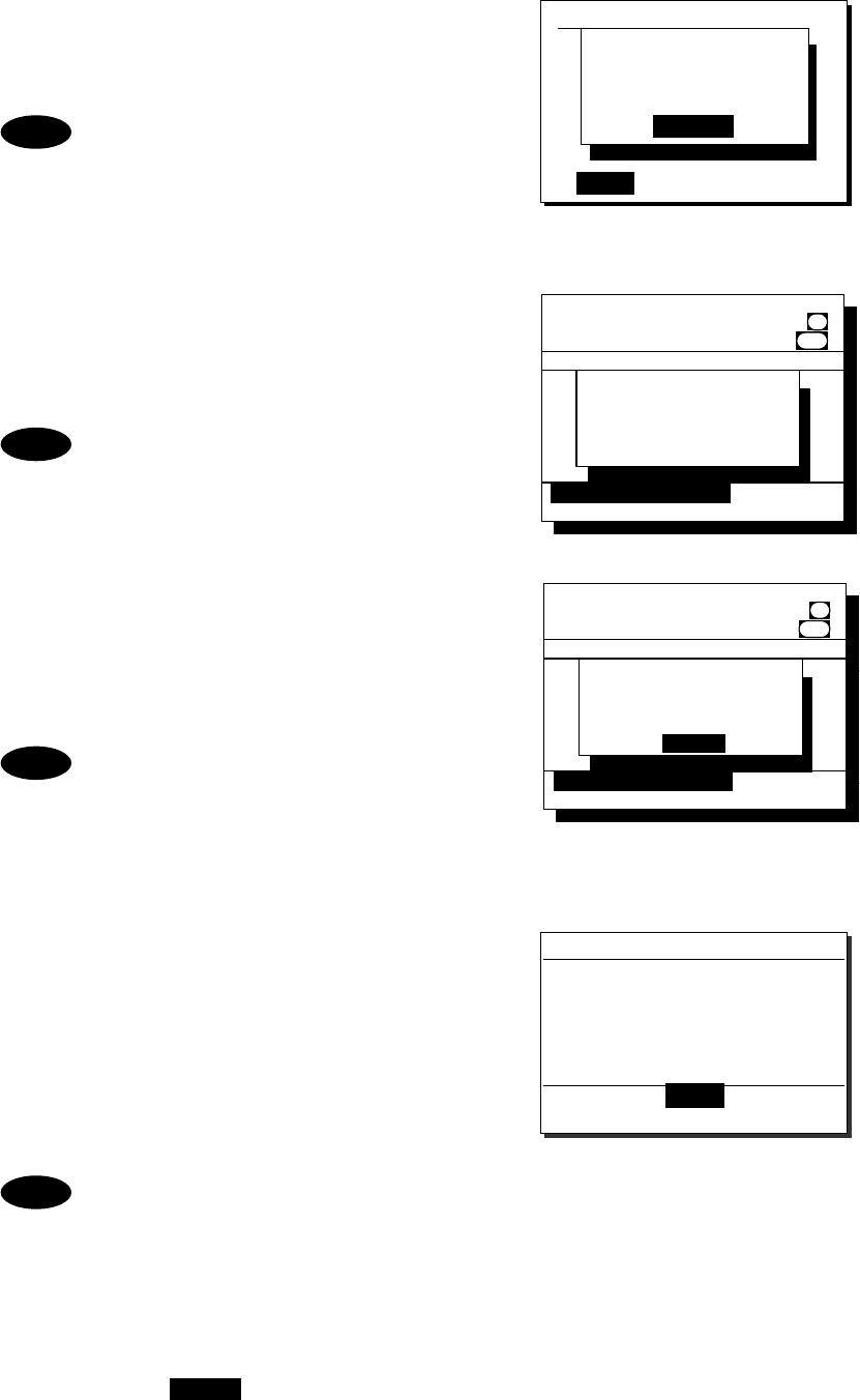
Operation
4-21
6
6
6.
.
.
Press ENT to transmit the call.
After completed the transmission, the popup
screen shown at right will be displayed to wait
the acknowledgement for 5 sec.
If received no response within 5sec,
sends the call again. Still no response,
the following will be displayed and
this call will be terminated.
"Coast sta no answer."
7
7
7.
.
.
After received the acknowledgement, the
specified working channel will be set
automatically.
After that, a start of call will be sent.
If lost the channel engaged signal,
the following will be displayed and
this call will be terminated.
"No signal detected in the Work CH."
8
8
8.
.
.
The PSTN connection will be completed.
Lift the handset from the cradle and wait for the
recipient answering the phone (the PSTN dial
tone and ring tone from the handset will be
heard at this time). After answered the phone,
the phone call charge will be started.
If not answered within 1 minute, the
following will be displayed and this call
will be terminated. (In the case of bad
radio link condition, this may also be
appeared during communication.)
"Lost the radio receiving signal."
9
9
9.
.
.
When finished the phone call, return the
handset to the cradle.
Then an end of call containing the duration will be
received from the coast station. The example at
right shows 13 minutes and 45 seconds.
- In the case of the duplex mode of the JHS-780D, the radiotelephone will always be
in sending condition. Nevertheless, pressing PTT key is needed to talk.
- According to the coast station, a negative acknowledgement mentioned above may
be received at step 7.
- If the negative acknowledgement indicates "unable to comply" with "Queue" reason,
the wait mode can be selected. This mode enables to continue the above procedure
from step 7 after receiving the ring back call. (However, if receiving no call within
15 minutes after receiving "Queue", the ring back mode is canceled. Also when
the CH16 key is pressed, the ring back mode is canceled.)
Note
1.3)PSTN call
Address:[001122334]
TEL No :[1234567890123456]
Mode :[Duplex ]
[Call] [Cancel]
Waiting for
Acknowledgement.
[Cancel]
Note
Note
Received routine message
Format :Semi/auto ACK
From :001234567
Type :End of call
Duration :00:13:45
TEL No :1122334455667788
EOS :ACK BQ
[ OK ]
Note
Received routine message
Format :Semi/auto ACK
From :001122334......
Type :All modes RT...
Work CH :03.............
TEL No. :1122334455612345
EOS :ACK BQ.........
Station1 TIME 23:59(UTC)
03 CH70
[OK/Lift handset] [Cancel]
Channel connection
completed.
Lift handset please.
CH [ITU]
DUP
[OK/Lift handset]
[ OK ]
Received routine message
Format :Semi/auto ACK
From :001122334......
Type :All modes RT...
Work CH :03.............
TEL No. :1122334455612345
EOS :ACK BQ.........
Station1 TIME 23:59(UTC)
03 CH70
[OK/Lift handset] [Cancel]
Sending message...
CH [ITU]
DUP
[OK/Lift handset]
Received routine message
Format :Semi/auto ACK
From :001122334......
Type :All modes RT...
Work CH :03.............
TEL No. :1122334455612345
EOS :ACK BQ.........
Station1 TIME 23:59(UTC)
03 CH70
[OK/Lift handset] [Cancel]
Sending message...
CH [ITU]
DUP
[OK/Lift handset]
Operation
4-22
(2) Receiving a call from a PSTN subscriber
■ Procedure ■
1
1
1.
.
.
The screen at right will be displayed, and
the alarm will sound.
The example message contains the following
information.
- Format: Semi/auto call
- Caller’s MMSI: 001222333
- Type: Radiotelephone
- Work Channel: CH03
- Caller TEL No: 00123459425
2
2
2.
.
.
After displayed the message as shown at
right, lift the handset from the cradle.
¾ If not answered within 1 minute, the PSTN
call will be cancelled.
¾ After lifting the handset or pressing ENT, a start
of call will be sent. If lost the channel engaged
signal, the following will be displayed and the
PSTN call will be terminated.
"No signal detected in the Work-CH."
¾ If interrupted the receiving signal for 5 seconds
during communication, the following will be
displayed and the PSTN call will be terminated.
"Lost the radio receiving signal."
3
3
3.
.
.
When finished the phone call, return the
handset to the cradle.
Then an end of call will be received from the
coast station. However, the duration of the call
will not be displayed for free of charge.
In the case of the duplex mode of the JHS-780D, the radiotelephone will always be in
sending condition. Nevertheless, pressing PTT key is needed to talk.
Received routine message
Format :Semi/auto ACK
From :001222333
Type :End of call
Duration :(Free of charge)
TEL No :00123459425
EOS :ACK BQ
[ OK ]
Note
Received routine message
Format :Semi/auto call
From :001222333
Type :All modes RT
Work CH :18
TEL No :00181422459425
EOS :ACK RQ
[OK/Lift handset] [Cancel]
Received PSTN call
from a coast sta.
And now setting
the PSTN mode...
Received routine message
Format :Semi/auto call
From :001222333
Type :All modes RT
Work CH :03
TEL No :00123459425
EOS :ACK RQ
[OK/Lift handset] [Cancel]
Operation
4-23
4.3.5 AIS-linked DSC calls
The AIS information (nearby ships call signs, names and identification numbers) will be displayed as
"Other ships list", and are available to call a listed ship via the DSC directly.
NOTE: To use this function, set the import condition to ON in the menu 9.6 AIS function.
■ Procedure ■
1
1
1.
.
.
Press FUNC Î 0AIS
¾ 5.1 Other ships list at right will be displayed.
¾ On the bottom line, the name and MMSI of the
ship highlighted by the cursor will be displayed.
¾ The bearings (BRG) are based on the North-up.
¾ If 5.2 Proximity check is ON, and the registered
ship on the 9.4.2 Ship station list is displayed,
v mark will be added on the ship's line.
¾ If existing no ships in the vicinity, "No data"
will be displayed on the middle of the screen.
The column(s) of the call sign, name or
MMSI will be blank when any of these has
not been entered to the ship's AIS, or when
not receiving the static information at the
AIS of own ship.
2
2
2.
.
.
Select a ship to call and press ENT using
the jog dial.
The popup screen at right will be displayed.
If the ship's MMSI has not been displayed,
this function will be disabled.
3
3
3.
.
.
Select a call type (category) and press ENT
using the jog dial.
The individual call menu for the selected category
will be displayed.
The example screen at right will show
the working channel input line for a
routine call, but for urgency calls to a
ship, inputting the working channel is
not needed (fixed to CH16).
4
4
4.
.
.
Press ENT and input the working channel.
- The free channel will be searched
and displayed automatically.
- If required, input another channel
manually using the CANCEL
key, the jog dial or the numeric
keys.
- If there is no free channel, a blank
will be shown as a search result.
5.1)Other ships list 01/11
BRG : RNG Call sign
10゚: 0.9NM JRCAAA
90゚: 1.2NM
45゚: 1.3NM
359゚: 2.0NM
221゚: 8.3NM
JRCBBB
JRCCCC
JRCDDD v
JRCEEE
Name: Pacific JRC
MMSI: 112233445
5.1)Other ships list 01/11
BRG : RNG Call sign
10゚: 0.9NM JRCAAA
90゚: 1.2NM
45゚: 1.3NM
359゚: 2.0NM
221゚: 8.3NM
JRCBBB
JRCCCC
JRCDDD R
JRCEEE
Name: Pacific JRC
MMSI: 112233445
VESSEL CALL PROCESS
Select call type.
[Routine][Safety]
[Urgency][Cancel]
Note
Note
Note
1.2)Ship station call
Address :[112233445]
Work CH :[ ]
[
OK
]
[
Cancel
]
1.2)Ship station call
Address :[112233445]
Work CH :[06]
[
OK
]
[
Cancel
]
Note
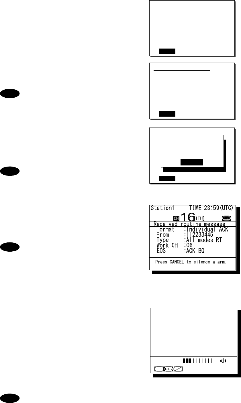
Operation
4-24
5
5
5.
.
.
Press ENT.
Confirm the entered contents.
6
6
6.
.
.
If the contents are correct, press ENT.
The sending confirmation screen will appear.
The controller displays by default only
the edited information in the call setup
as shown at right.
7
7
7.
.
.
Press ENT to transmit the call.
After completed the transmission, the popup
screen shown at right will be displayed to wait
the acknowledgement.
If received no response for 5 minutes,
the screen will return to the step 5
mentioned above.
8
8
8.
.
.
When received the acknowledgement, the
screen shows the message with the alarm
for 3 sec. Then changes to the proposed
working channel automatically.
- If 9.5.2 Automatic CH shift is OFF,
lifting the handset or pressing ENT
is required to set the proposed
working channel.
- If an improper channel is proposed,
resend the call containing a new
channel via the specified new
channel proposal form screen.
9
9
9.
.
.
The ship station call will be completed
after displayed the working channel as
shown at right.
Start communications using the handset.
¾ The example at right shows when proposed
CH06 as a working channel.
¾ When completed the communications,
return the handset to the cradle.
If the ship station is unable to comply with the call, as with coast stations, own station
(caller) may receive a negative acknowledgement mentioned above section. In this
case, if possible according to the message, wait and retry the calling again later.
Note
1.2)Ship station call
Address :112233445
Work CH :06
[
Call
]
[
Cancel
]
Note
1.2)Ship station call
Address :[112233445]
Work CH :[06]
[
OK
]
[
Cancel
]
1.2)Ship station call
Address :123456789
Work CH :71
[
Call
]
[
Cancel
]
Waiting for
Acknowledgement.
[Cancel]
Note
Note
Station1 TIME 23:59(UTC)
POS 89゚59'S
EXT 179゚59'W
06
CH
CH70
[ITU]
SQL
CHSW
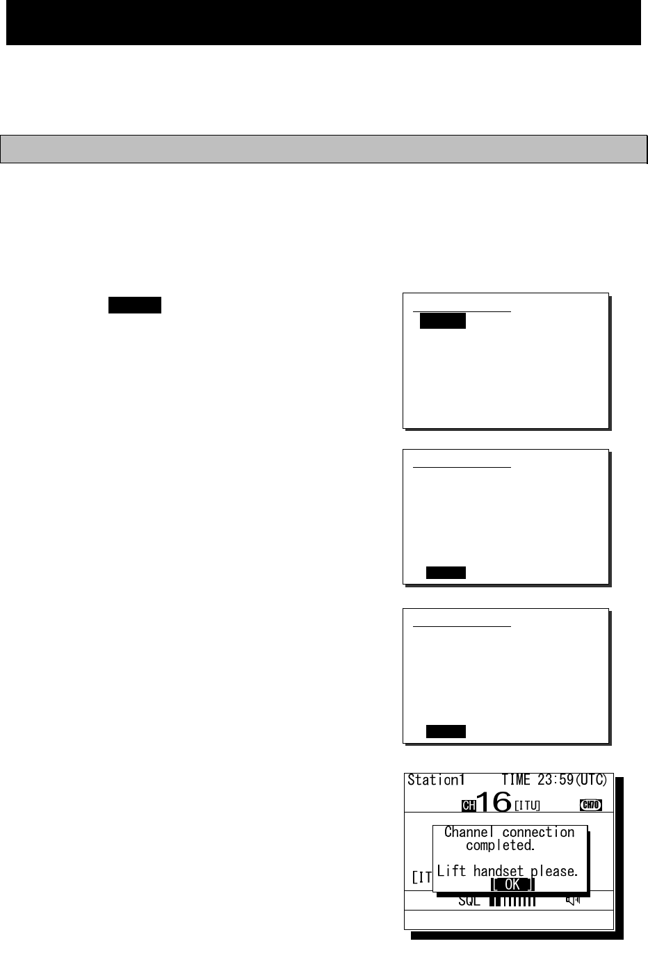
Operation
4-25
4.4 Emergency calls (DSC safety/ urgency/ distress calls)
In emergency, the DSC is available for safety/ urgency/ or distress calls. For safety and urgency calls,
either individual or all ships is selectable for the type of call. For distress calls, enabled to send either
after selecting the nature of distress or without selecting it. In both cases, when own ship is in
distress, pressing the dedicated distress key for 4seconds is required to send the distress call.
4.4.1 Safety calls
4.4.1.1 All ships calls
When broadcasting to all ships regarding safety, the all ships call is available.
■ Procedure ■
1
1
1.
.
.
Press the MENU key, and through
hierarchical menus, select the 2.1.1 All
ships.
The working channel inputting form will be displayed.
Normally the CH16 by default is used.
2
2
2.
.
.
Select OK with the jog dial.
3
3
3.
.
.
Press ENT.
The sending confirmation screen will appear.
4
4
4.
.
.
Press ENT to transmit the call.
All ships call needs no response and will be
completed after displayed the popup screen as
shown at right. Lifting the handset or pressing
ENT erases the popup screen, and enables to
start the communication.
2.1.1)All ships
Work CH :[16]
[
OK
]
[
Cancel
]
2.1.1)All ships
Work CH :[16]
[
OK
]
[
Cancel
]
2.1.1)All ships
Format :All ships call
Type :All modes RT
Work CH :16
[
Call
]
[
Cancel
]
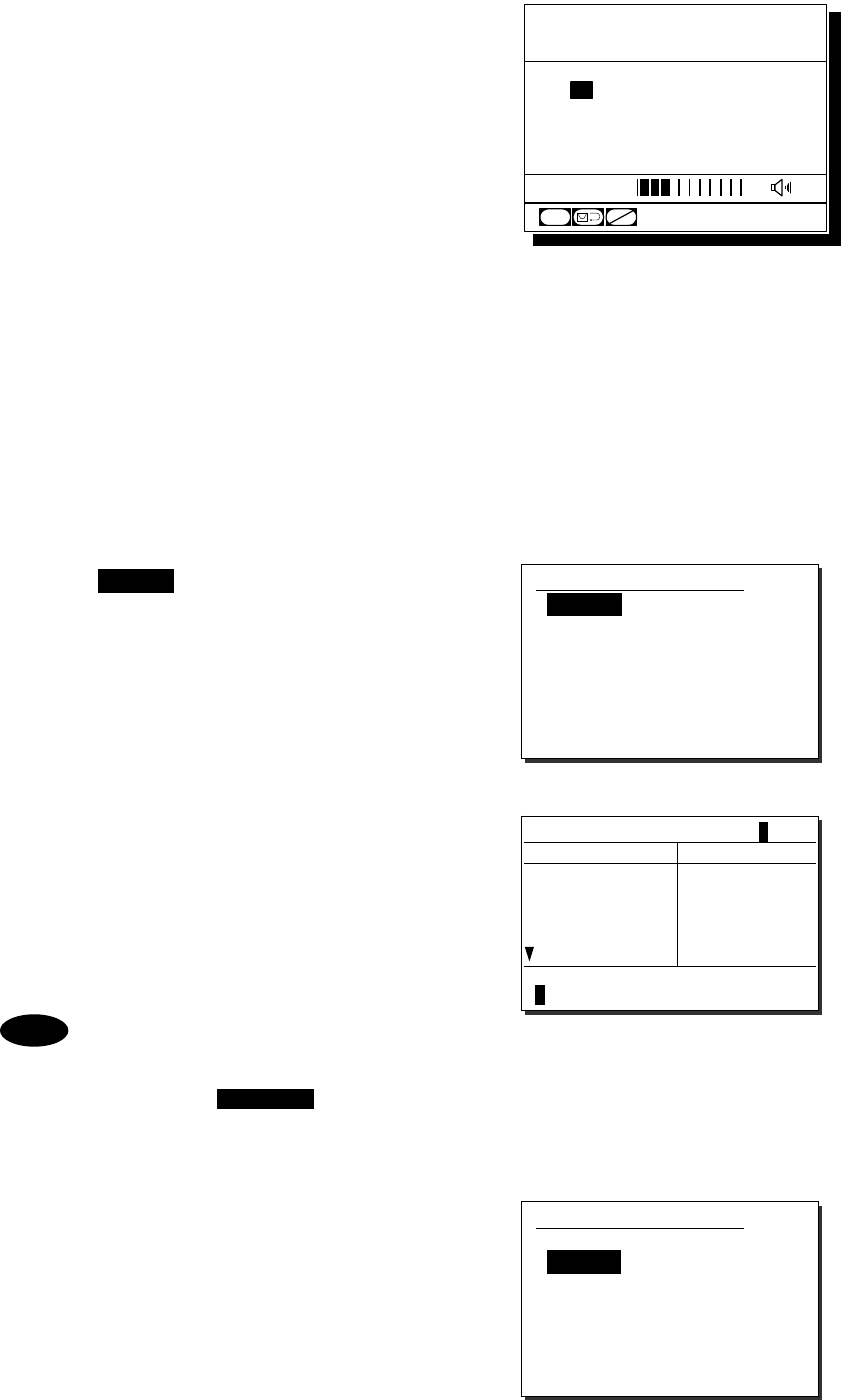
Operation
4-26
5
5
5.
.
.
Start the safety broadcasting using the
handset.
When completed the communications, return
the handset to the cradle.
4.4.1.2 Individual calls (All modes RT)
When sending the safety individual call to a ship or coast station, note the difference described below
from the case of routine.
・ The menu is common for both ship and coast station.
・ Other than the address and the working channel, the type is needed to select.
・ Normally the CH16 by default is used.
■ Procedure ■
1
1
1.
.
.
Press the MENU key, and through
hierarchical menus, select the 2.1.2 Specific
station.
The menu shown at right will be displayed.
If entered previously, the address will be
appeared as a default value
2
2
2.
.
.
Press ENT to display the station list,
and select the desired station with the
jog dial.
The procedure is similar to that of routine calls,
except that the list shows together ship stations
and coast stations.
- The list can be registered in the
menu 9.4 Contact list.
- When inputting the MMSI manually,
press the CANCEL key to return
to the previous screen and input it
using the numeric keypad.
3
3
3.
.
.
Press ENT.
The cursor will move to the Type.
2.1.2)Specific station
Address :[ ]
Type :[All modes RT]
Work CH :[16]
[
OK
]
[
Cancel
]
2.1.2)Specific station
Address :[123456789]
Type :[All modes RT]
Work CH :[16]
[
OK
]
[
Cancel
]
Station1 TIME 23:59(UTC)
POS 89゚59'S
EXT 179゚59'W
16
CH
SQL
CH70
CHSW
[ITU]
Station list [A]
NAME MMSI
AAA ocean 123456789
ABB ocean
ABC ocean
ACC ocean
BBB ocean
222222222
333333333
444444444
555555555
Select the initial of the name.
ABCDEFGHIJKLMNOPQRSTUVWXYZ
Note
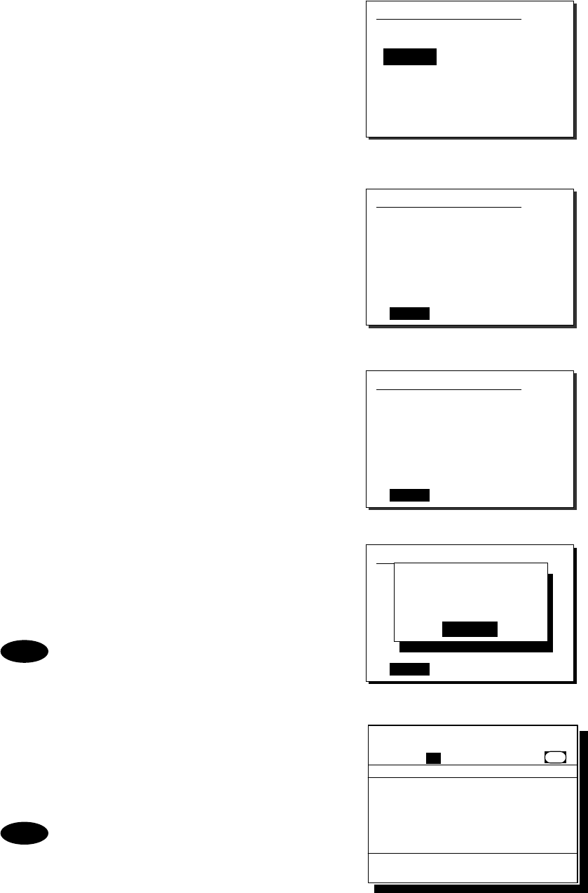
Operation
4-27
4
4
4.
.
.
Press ENT and select a type of call with the
jog dial. If intending to voice communication
after the call, leave it as "All modes RT",
and move the cursor to Work CH.
The following types are selectable.
- All modes RT (for Radiotelephone)
- Position RQ (Position request)
- Test (Safety test)
5
5
5.
.
.
Normally, use CH16 for the communication
of safety and move the cursor to OK with
the jog dial.
If required to change the working channel,
press ENT and input the channel at the step 4.
6
6
6.
.
.
If the contents are correct, press ENT.
The sending confirmation screen will appear.
7
7
7.
.
.
Press ENT to transmit the call.
After completed the transmission, the popup
screen shown at right will be displayed to wait
the acknowledgement.
If received no response for 5 minutes,
the screen will return to the step 5
mentioned above.
8
8
8.
.
.
When received the acknowledgement,
the screen shows the message with the
alarm for 3 sec. Then changes to the
proposed working channel automatically.
- If 9.5.2 Automatic CH shift is OFF,
lifting the handset or pressing ENT is
required to set the proposed working
channel.
- If an improper channel is proposed,
resend the call after inputting a new
channel proposal.
2.1.2)Specific station
Address :[123456789]
Type :[All modes RT]
Work CH :[16]
[
OK
]
[
Cancel
]
2.1.2)Specific station
Address :123456789
Work CH :71
[
Call
]
[
Cancel
]
Waiting for
Acknowledgement.
[Cancel]
Note
2.1.2)Specific station
Address :[123456789]
Type :[All modes RT]
Work CH :[16]
[
OK
]
[
Cancel
]
2.1.2)Specific station
Address :123456789
Type :All modes RT
Work CH :16
[
Call
]
[
Cancel
]
Note
Received safety message
Format :Individual ACK
From :123456789......
Type :All modes RT...
Work CH :16.............
EOS :ACK BQ.........
Station1 TIME 23:59(UTC)
16
CH70
Press CANCEL to silence alarm.
CH [ITU]
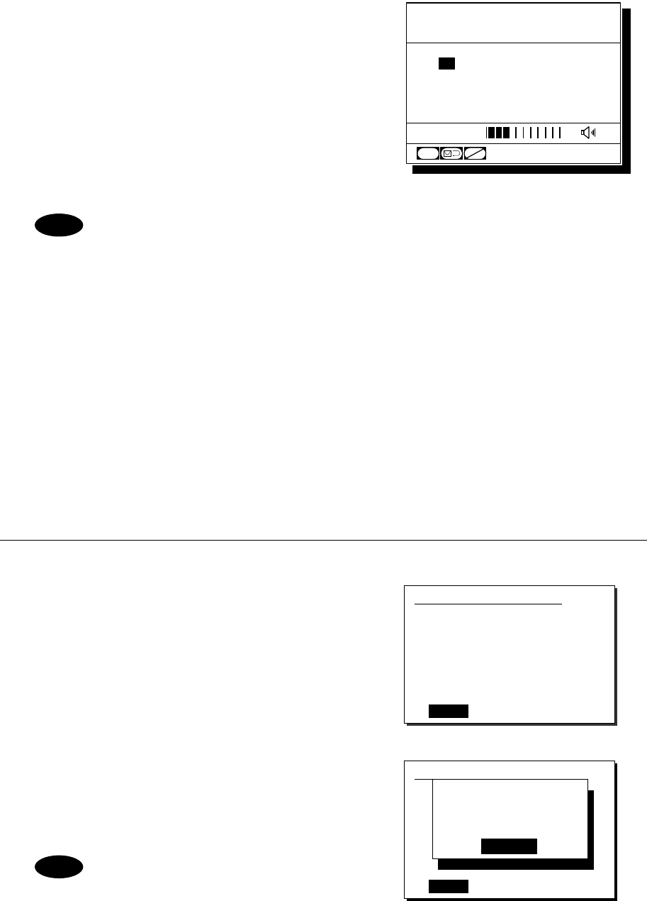
Operation
4-28
9
9
9.
.
.
The call will be completed after displayed
the working channel as shown at right.
Start communications using the handset.
¾ The example at right shows when proposed
CH16 as a working channel.
¾ When completed the communications,
return the handset to the cradle.
If the called station is unable to comply with the call, as with routine calls, own station
(caller) may receive a negative acknowledgement mentioned above section. In this
case, if possible according to the message, wait and retry the calling again later.
4.4.1.3 Other features of the safety call (Position request/ Test)
Additional features of safety call, such as a ship position request call or a DSC test call are available.
In these cases, there is no voice communication and not needed to set a working channel.
However, the procedures are otherwise identical to those mentioned above, so describes below after
completed the editing steps.
(1) Position request call
■ Procedure ■
1
1
1.
.
.
After inputting the ship's address and type
(Position RQ), the sending confirmation
screen will appear.
2
2
2.
.
.
Press ENT to transmit the call.
After completed the transmission, the popup
screen shown at right will be displayed to wait
the acknowledgement.
If received no response for 5 minutes,
the screen will return to the editing
screen.
Note
2.1.2)Specific station
Address :123456789
Type :Position RQ
[
Call
]
[
Cancel
]
2.1.2)Specific station
Address :123456789
Work CH :71
[
Call
]
[
Cancel
]
Waiting for
Acknowledgement.
[CANCEL]
Note
Station1 TIME 23:59(UTC)
POS 89゚59'S
EXT 179゚59'W
16
CH
SQL
CH70
CHSW
[ITU]
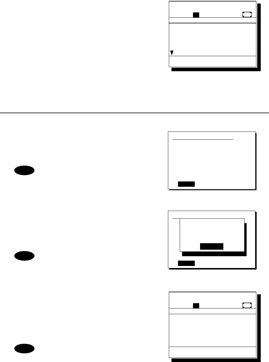
Operation
4-29
3
3
3.
.
.
When received the acknowledgement,
the screen shows the message with the
alarm as shown at right.
Pressing CANCEL stops alarm and after that,
pressing ENT returns to the status display.
(2) Test call
■ Procedure ■
1
1
1.
.
.
After inputting the ship's address and
type (Test), the sending confirmation
screen will appear.
The test call is also available in
menu 3. DSC test call, by entering
the station address only.
2
2
2.
.
.
Press ENT to transmit the call.
After completed the transmission, the popup
screen shown at right will be displayed to wait
the acknowledgement.
If received no response for 5 minutes,
the screen will return to the step 1
mentioned above.
3
3
3.
.
.
When received the acknowledgement,
the screen shows the message with the
alarm as shown at right.
Pressing CANCEL stops alarm and after that,
pressing ENT returns to the status display.
According to the condition of the station,
the acknowledgement may not be received
even if the equipment works normally.
2.1.2)Specific station
Address :123456789
Type :Test
[
Call
]
[
Cancel
]
2.1.2)Specific station
Address :123456789
Work CH :71
[
Call
]
[
Cancel
]
Waiting for
Acknowledgement.
[Cancel]
Note
Note
Note
Received safety message
Format :Individual ACK
From :123456789......
Type :Ship position..
Position :12゚34'N........
123゚45'E.......
UTC :12:34..........
Station1 TIME 23:59(UTC)
16
CH70
Press CANCEL to silence alarm.
CH [ITU]
Received safety message
Format :Individual ACK
From :123456789......
Type :Test...........
EOS :ACK BQ.........
Station1 TIME 23:59(UTC)
16
CH70
Press CANCEL to silence alarm.
CH [ITU]
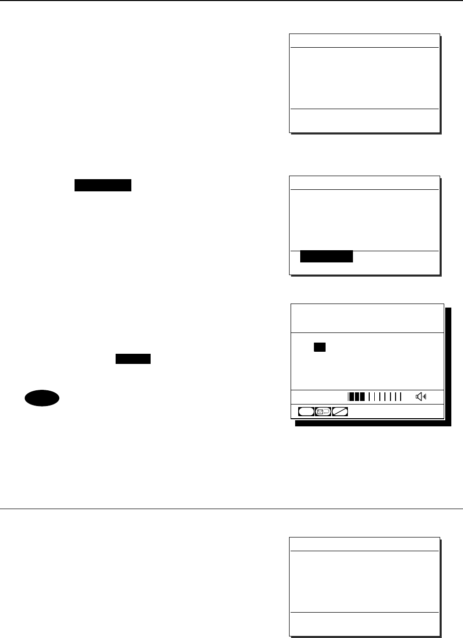
Operation
4-30
4.4.1.4 Receiving a safety call
When receiving a safety call from a coast station or another ship station, the message will be displayed
immediately. Then treat the message according to the type as below.
(1) Receiving an all ships call
■ Procedure ■
1
1
1.
.
.
The screen at right will be displayed, and
the alarm will sound.
The example message contains the following
information.
- Format: All ships call
- Caller’s MMSI: 111222333
- Type: All modes Radiotelephone
- Work Channel: CH16
- EOS: End of sequence.
2
2
2.
.
.
Press the CANCEL key to stop the alarm
and display the screen at right.
3
3
3.
.
.
If possible to listen to the broadcast, press
ENT to set the working channel.
When finished the broadcast used except for
the CH16, press the CH16 key to return to
the status display.
If Automatic CH shift is ON, the working
channel will be changed automatically
and the above step 2 and 3 are omitted.
(2) Receiving an individual call (Type: Radiotelephone)
This procedure is identical to the case of a
routine call. However the screen shown at
right will be displayed with the alarm.
Received safety message
Format :All ships call
From :111222333
Type :All modes RT
Work CH :16
EOS :EOS
Press CANCEL to silence alarm.
Received safety message
Format :All ships call
From :111222333
Type :All modes RT
Work CH :16
EOS :EOS
[OK/Listen] [Cancel]
Received safety message
Format :Individual call
From :111222333
Type :All modes RT
Work CH :16
EOS :ACK RQ
Press CANCEL to silence alarm.
Note
Station1 TIME 23:59(UTC)
POS 89゚59'S
EXT 179゚59'W
16
CH
SQL
CH70
CHSW
[ITU]
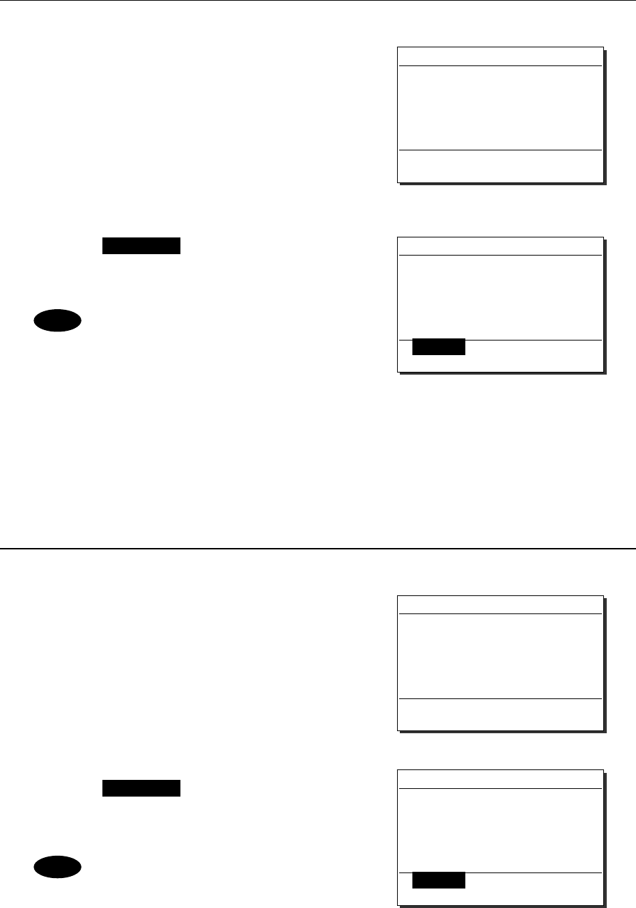
Operation
4-31
(3) Receiving an individual call (Type: Position request)
■ Procedure ■
1
1
1.
.
.
The screen at right will be displayed, and
the alarm will sound.
The example message contains the following
information.
- Format: Individual call
- Caller’s MMSI: 111222333
- Type: Position request
- EOS: ACK is requested.
2
2
2.
.
.
Press the CANCEL key to stop the alarm
and display the screen at right. If possible to
respond immediately, press ENT.
- If Automatic ACK is ON, the
acknowledgement will be sent
automatically without notice.
- If having no position information
(unconnected to GPS and elapsed over
23.5 hours after inputting manually),
the message editing screen will be
displayed after selecting the OK/ACK.
(4) Receiving an individual call (Type: Test)
■ Procedure ■
1
1
1.
.
.
The screen at right will be displayed, and
the alarm will sound.
The example message contains the following
information.
- Format: Individual call
- Caller’s MMSI: 111222333
- Type: Test
- EOS: ACK is requested.
2
2
2.
.
.
Press the CANCEL key to stop the alarm
and display the screen at right. If possible
to respond immediately, press ENT.
If Automatic ACK is ON, the
acknowledgement will be sent
automatically without notice.
Received safety message
Format :Individual call
From :111222333
Type :Position RQ
EOS :ACK RQ
[OK/ACK] [Cancel]
Received safety message
Format :Individual call
From :111222333
Type :Position RQ
EOS :ACK RQ
Press CANCEL to silence alarm.
Note
Received safety message
Format :Individual call
From :111222333
Type :Test
EOS :ACK RQ
[OK/ACK] [Cancel]
Received safety message
Format :Individual call
From :111222333
Type :Test
EOS :ACK RQ
Press CANCEL to silence alarm.
Note
Operation
4-32
4.4.2 Urgency calls
4.4.2.1 All ships calls
When broadcasting to all ships regarding urgency, the all ships call is available.
■ Procedure ■
1
1
1.
.
.
Press the MENU key, and through
hierarchical menus, select 2.2.1 All ships.
Normally, this call uses a fixed message, and the
sending confirmation screen will appear immediately.
Regarding calls for medical transport
and neutral ships, additional procedures
are required. See 4.4.2.3 for details.
2
2
2.
.
.
Press ENT to transmit the call.
All ships call needs no response and will be
completed after displayed the popup screen as
shown at right. Lifting the handset or pressing
ENT erases the popup screen, and enables to
start the communication.
If the handset has been left in the
off-hook condition in advance, skip
to step 3 below without showing the
popup screen at right.
3
3
3.
.
.
Start the urgency broadcasting using the
handset.
When completed the communications, return
the handset to the cradle.
2.2.1)All ships
Format :All ships call
Type :All modes RT
Work CH :16
[
Call
]
[
Cancel
]
Note
Station1 TIME 23:59(UTC)
POS 89゚59'S
EXT 179゚59'W
16
CH
SQL
CH70
CHSW
[ITU]
Note
Operation
4-33
4.4.2.2 Individual calls
When sending the urgency individual call to a ship or coast station, the procedures are basically as
described below.
・ The menu is common for both ship and coast station.
・ Only required to input the address.
・ The working channel is fixed on CH16.
■ Procedure ■
1
1
1.
.
.
Press the MENU key, and through
hierarchical menus, select the 2.2.2 Specific
station.
The menu shown at right will be displayed.
If entered previously, the address will be
appeared as a default value
2
2
2.
.
.
Press ENT to display the station list,
and select the desired station with the
jog dial.
This procedure is identical to the case of the
safety call.
3
3
3.
.
.
Press ENT.
Confirm the address.
4
4
4.
.
.
If the contents are correct, press ENT.
The sending confirmation screen will appear.
2.2.2)Specific station
Address :[ ]
[
OK
]
[
Cancel
]
2.2.2)Specific station
Address :[123456789]
[
OK
]
[
Cancel
]
2.2.2)Specific station
Address :123456789
[
Call
]
[
Cancel
]
Station list [A]
NAME MMSI
AAA ocean 123456789
ABB ocean
ABC ocean
ACC ocean
BBB ocean
222222222
333333333
444444444
555555555
Select the initial of the name.
ABCDEFGHIJKLMNOPQRSTUVWXYZ
Operation
4-34
5
5
5.
.
.
Press ENT to transmit the call.
After completed the transmission, the popup
screen shown at right will be displayed to wait
the acknowledgement.
If received no response for 5 minutes,
the screen will return to the step 3
mentioned above.
6
6
6.
.
.
When received the acknowledgement,
the screen shows the message with the
alarm for 3 sec. Then changes to the
working channel (CH16) automatically.
- If 9.5.2 Automatic CH shift is OFF,
lifting the handset or pressing ENT is
required to set the working channel.
- The specific alarm for urgency sounds
and notifies the receiving of the
acknowledgement.
7
7
7.
.
.
The station call will be completed after
displayed the working channel as shown
at right.
Start communications using the handset.
When completed the communications, return
the handset to the cradle.
If the called ship or coast station is unable to comply with the call, own station (caller)
may receive a negative acknowledgement with the reason mentioned above. In this
case, if possible according to the message, wait and retry the calling again later.
2.2.2)Specific station
Address :123456789
Work CH :71
[
Call
]
[
Cancel
]
Waiting for
Acknowledgement.
[Cancel]
Note
Note
Note
Station1 TIME 23:59(UTC)
POS 89゚59'S
EXT 179゚59'W
16
CH
SQL
CH70
CHSW
[ITU]
Received urgency message
Format :Individual ACK
From :123456789......
Type :All modes RT...
Work CH :16.............
EOS :ACK BQ.........
Station1 TIME 23:59(UTC)
16
CH70
Press CANCEL to silence alarm.
CH [ITU]
Operation
4-35
4.4.2.3 Special calls (Medical transport/ Neutral ship)
When sailing dangerous waters such as political instability, the urgency all ships call containing the
additional subject is available to inform others of the following information concerned.
・ Own ship is performing medical transportation and protected under the 1949 Geneva Convention.
・ Own ship is of neutral nationality.
■ Procedure ■
1
1
1.
.
.
Set the 9.5.4 Medical/Neutral use to ON,
before this call operation.
- This setting is always reset to the
default value (OFF) after powering
off/on.
- Receiving these calls are always
possible regardless of the setting.
2
2
2.
.
.
Press the MENU key, and through
hierarchical menus, select 2.2.1 All ships.
The subject selection form for urgency all ships
call will be displayed.
3
3
3.
.
.
Press ENT and select the subject to be added
to the call message with the jog dial.
Select a subject from below.
- No info (for No information)
- Medical TRNSP (for Medical transport)
- Neutral ship (for Neutral nationality)
4
4
4.
.
.
Press ENT.
The cursor will move to OK.
5
5
5.
.
.
If the content is correct, press ENT.
The sending confirmation screen will appear.
2.2.1)All ships
Subject :[Medical TRNSP]
[
OK
]
[
Cancel
]
9.5)DSC operation
1.Automatic ACK :ON
2.Automatic CH shift :ON
3.Safety/Routine ALM :ON
4.Medical/Neutral use :ON
5.Expanded MMSI : 0
0.Back
Note
2.2.1)All ships
Subject :[No info ]
[
OK
]
[
Cancel
]
2.2.1)All ships
Format :All ships call
Type :All modes RT
Work CH :16
[
Call
]
[
Cancel
]
2.2.1)All ships
Subject :[Medical TRNSP]
[
OK
]
[
Cancel
]
Operation
4-36
6
6
6.
.
.
Press ENT to transmit the call.
All ships call needs no response and will be
completed after displayed the popup screen as
shown at right. Lifting the handset or pressing
ENT erases the popup screen, and enables to
start the communication.
If the handset has been left in the
off-hook condition in advance, skip
to step 7 below without showing the
popup screen at right.
7
7
7.
.
.
Start the urgency broadcasting using the
handset.
When completed the communications, return
the handset to the cradle.
4.4.2.4 Receiving an urgency call
When receiving an urgency call from a coast or another ship station, the message will be displayed
immediately with the specific alarm for urgency calls. Then treat the message according to the type as
below.
(1) Receiving an all ships call
■ Procedure ■
1
1
1.
.
.
The screen at right will be displayed, and the
alarm will sound growing louder gradually.
The example message contains the following
information.
- Format: All ships call
- Caller’s MMSI: 111222333
- Type: All modes radiotelephone
- Work Channel: CH16
- EOS: End of sequence.
When containing additional information
regarding Medical TRNSP or Neutral
ship, the Subject line will be added.
2
2
2.
.
.
Press the CANCEL key to stop the
alarm, and display the screen at right.
Received urgency message
Format :All ships call
From :111222333
Type :All modes RT
Work CH :16
EOS :EOS
Press CANCEL to silence alarm.
Received urgency message
Format :All ships call
From :111222333
Type :All modes RT
Work CH :16
EOS :EOS
[OK/Listen] [Cancel]
Note
Station1 TIME 23:59(UTC)
POS 89゚59'S
EXT 179゚59'W
16
CH
SQL
CH70
CHSW
[ITU]
Note
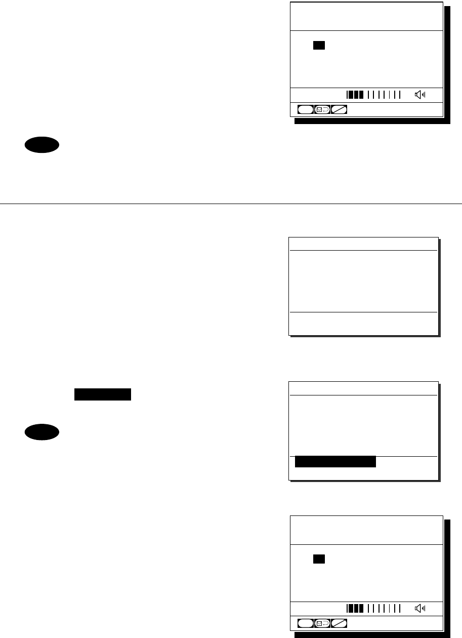
Operation
4-37
3
3
3.
.
.
If possible to listen to the broadcast, press
ENT to set the working channel.
If receiving the call containing the information regarding the medical transport or the
neutral ship, the message will show it as the "Subject".
(2) Receiving an Individual Call
■ Procedure ■
1
1
1.
.
.
The screen at right will be displayed, and the
alarm will sound growing louder gradually.
The example message contains the following
information.
- Format: Individual call
- Caller’s MMSI: 111222333
- Type: All modes radiotelephone
- Work channel: CH16
- EOS: ACK is requested.
2
2
2.
.
.
Press the CANCEL key to stop the
alarm and display the screen at right.
This step is omissible.
3
3
3.
.
.
If possible to communicate immediately,
lift the handset from the cradle and start
the communications.
¾ In this example case, enabled to select the
response from below with the jog dial.
・OK/Lift handset: Starts communications
immediately.
・Unable/NACK: Sends "Unable to comply"
message with that reason.
・Cancel: Returns to the status display
without handling this message.
¾ When completed the communications, return the
handset to the cradle.
Received urgency message
Format :Individual call
From :111222333
Type :All modes RT
Work CH :16
EOS :ACK RQ
Press CANCEL to silence alarm.
Received urgency message
Format :Individual call
From :111222333
Type :All modes RT
Work CH :16
EOS :ACK RQ
[OK/Lift handset]
[Unable/NACK] [Cancel]
Note
Station1 TIME 23:59(UTC)
POS 89゚59'S
EXT 179゚59'W
16
CH
SQL
CH70
CHSW
[ITU]
Station1 TIME 23:59(UTC)
POS 89゚59'S
EXT 179゚59'W
16
CH
SQL
CH70
CHSW
[ITU]
Note
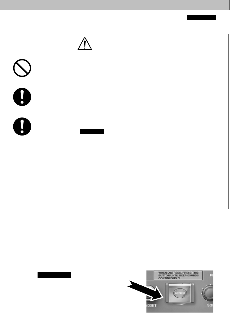
Operation
4-38
4.4.3 Distress calls (Distress alerts)
When in distress, distress calls are always transmitted by pressing the dedicated DISTRESS key.
The distress calls transmit own MMSI, ships position, time of the position, and the nature of distress.
CAUTION
Do not test the distress call as doing so will inconvenience local shipping and
Rescue Centers.
When sending a distress call, follow the instructions of the ship's captain or
officer in charge.
If a false distress call is transmitted accidentally, follow the instructions below:
1. Press the CANCEL key on the controller (when appropriate, follow the
commands on screen) and terminate the transmission of the distress call.
2. Report the false distress call to a nearby RCC (Rescue Coordination
Center).
(In Japan, inform the nearest Japan Coast Guard.)
Information to be reported:
The date/time, location, and reason why the false call was transmitted.
Also report the ship's name, type, nationality, ID number as well as the unit
model name and manufacture number/date, if possible.
3. Report the false distress call to nearby ships using CH16.
4. If any acknowledgements to the distress call are received, inform the ships
of the false distress call.
4.4.3.1 Quick distress calls
The following describes the procedure to send a distress call immediately without using menus. In
this case, the nature of distress in the message will be sent as "Undesignated" by default. Further, if
no information for the position and the time of position obtained within 23.5 hours, these information
will be composed automatically as "9999999999" and "8888" respectively.
■ Procedure ■
1
1
1.
.
.
Open the DISTRESS key cover.
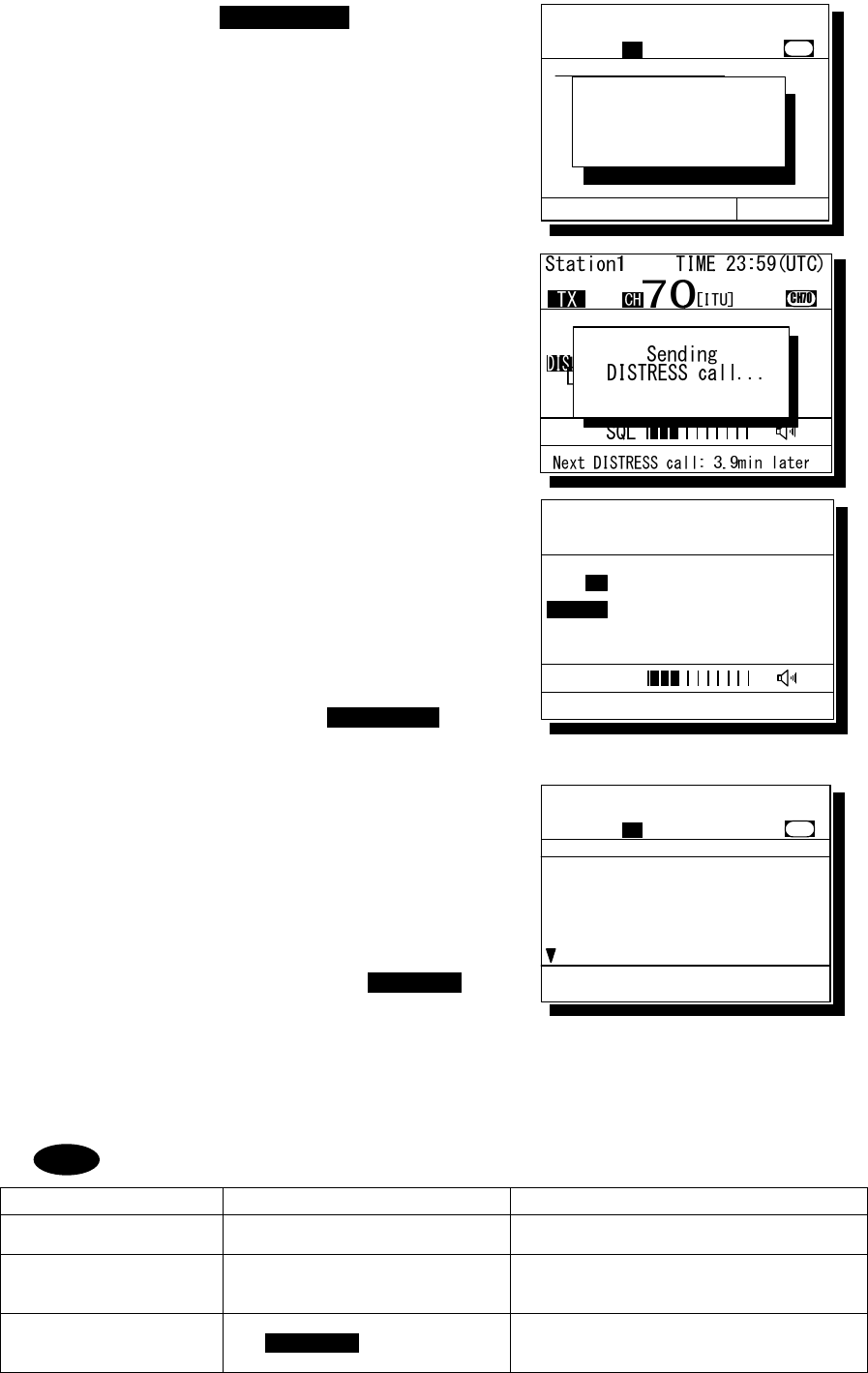
Operation
4-39
2
2
2.
.
.
Press and hold the DISTRESS key for 4
seconds until the countdown is completed.
If released before the countdown is completed,
displays the menu of 2.3 Distress call for the
nature of distress selection.
3
3
3.
.
.
The distress call will be sent.
4
4
4.
.
.
Automatically remained in distress mode
until received the acknowledgement.
¾ The distress call will be automatically repeated
every 3.5 - 4.5 minutes until received the
acknowledgement or manually breaks the mode.
(The bottom line indicates the remaining time
until the next distress call.)
¾ The distress call can be sent as many times as
needed in this condition by the DISTRESS
key operation mentioned above.
5
5
5.
.
.
When acknowledged, the screen at right will
be displayed and the alarm will sound
growing louder gradually. Then lift the
handset and request rescue using CH16 of
the radiotelephone.
¾ The ALM lamp blinks in sync with the alarm sound.
¾ Only to silence the alarm, press the CANCEL
key when displaying the screen at right.
¾ First, the responding station will call on the CH16,
then acknowledge the receipt as follows.
z "MAYDAY",
z "this is",
z Own ship's MMSI and call sign, position, nature of distress, and rescue requests
The following popup screens will be displayed as appropriate in distress mode.
Popup message Contents Notes
Attention!/Restarting
distress call soon…
Notifies that the distress call will
be resent within 12 seconds.
Received other call.
Break DISTRESS mode
to view message?
Equipment received a call but not
the acknowledgement.
To continue distress mode, select [Continue], or
to cancel distress mode to check the received
DSC call, select [Break]
Now continuing
DISTRESS call mode.
Break this mode?
Confirmation screen when pressed
the CANCEL key in distress
mode
To continue distress mode, select [Continue], or
to cancel distress mode, select [Break]
Note
Station1 TIME 23:59(UTC)
POS 89゚59'S
EXT 179゚59'W
16
CH
DISTRESS
Next DISTRESS call: 3.9min later
SQL
[ITU]
2.3)Distress call
Nature :[Fire ]
Position:[NE] .
[ 12゚34.5678'N]
[123゚45.6789'E]
UTC :[12:20] .
Station1 TIME 23:59(UTC)
CH
70
CH70
Nature
Press DISTRESS to send. [Cancel]
DISTRESS call
starts in
4 sec
[ITU]
Received Acknowledgement
Type :Distress ACK...
To :All ships .....
From :001234567......
Dist-ID :987654321......
Nature :Undesignated
Position :34゚00.1234'N...
Station1 TIME 23:59(UTC)
16
CH70
Press CANCEL to silence alarm.
CH [ITU]
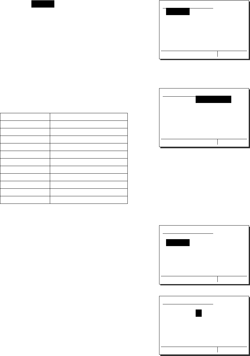
Operation
4-40
4.4.3.2 Distress calls from the menu
The following describes the procedure to send a distress call with the nature of distress selected in the
menu. Also, if there is no valid information regarding the position and the time of position, the manual
input is available in that menu.
■ Procedure ■
1
1
1.
.
.
Press the MENU key, and through
hierarchical menus, select the 2.3 Distress
call.
Indicates "Undesignated" as the nature of
distress by default, and the position information
if obtained from a GPS automatically or entered
manually.
2
2
2.
.
.
Press ENT and select the nature of distress.
The nature of distress is selectable from below.
Nature of distress Contents
Fire Fire, explosion
Flooding Flooding
Collision Collision
Grounding Grounding
Listing Listing, in danger of capsizing
Sinking Sinking
Disabled Disabled and adrift
Undesignated Undesignated distress
Abandoning Abandoning ship
Piracy attack Piracy/armed robbery attack
Man overboard Man overboard
3
3
3.
.
.
Press ENT.
The cursor will move to Position.
If already displayed the valid position and time of
position, no entry is necessary and skip to step 7.
4
4
4.
.
.
Press ENT and select the quadrant of the
position with the jog dial.
The quadrant will be changed as NE → NW →
SE → SW.
2.3)Distress call
Nature :[Undesignated ]
Position:[NE]
[ 12゚34.5678'N]
[123゚45.6789'E]
UTC :[12:20]
Press DISTRESS to send.
[Cancel]
2.3)Distress call
Nature :[Undesignated ]
Position:[NE]
[ 12゚34.5678'N]
[123゚45.6789'E]
UTC :[12:20]
Press DISTRESS to send.
[Cancel]
2.3)Distress call
Nature :[Flooding ]
Position:[NE]
[ 12゚34.5678'N]
[123゚45.6789'E]
UTC :[12:20]
Press DISTRESS to send.
[Cancel]
2.3)Distress call
Nature :[Flooding ]
Position:[NE]
[ 12゚34.5678'N]
[123゚45.6789'E]
UTC :[12:20]
Press DISTRESS to send.
[Cancel]
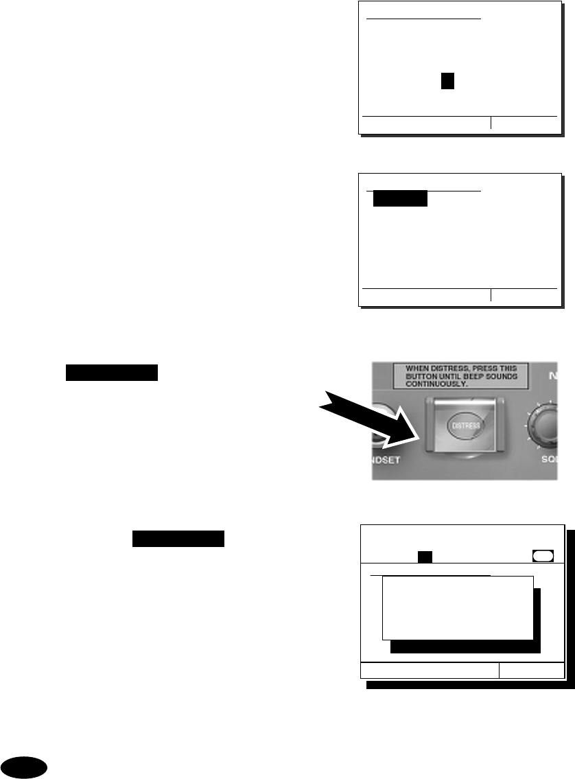
Operation
4-41
5
5
5.
.
.
After pressing ENT, input the latitude and
longitude using the numeric keypad.
After registered the every digit, input the UTC.
6
6
6.
.
.
After completed the registrations, the
cursor will return to Nature.
7
7
7.
.
.
Open the DISTRESS key cover.
8
8
8.
.
.
Press and hold the DISTRESS key for 4
seconds until the countdown is completed.
The rest of the procedure is the same as described in the "Quick distress call".
2.3)Distress call
Nature :[Flooding ]
Position:[NE]
[ 34゚00.1234'N]
[140゚00.1234'E]
UTC :[12:20]
Press DISTRESS to send.
[Cancel]
2.3)Distress call
Nature :[Flooding ]
Position:[NE]
[ 34゚00.1234'N]
[140゚00.1234'E]
UTC :[12:34]
Press DISTRESS to send.
[Cancel]
Note
2.3)Distress call
Nature :[Fire ]
Position:[NE] .
[ 12゚34.5678'N]
[123゚45.6789'E]
UTC :[12:20] .
Station1 TIME 23:59(UTC)
CH
70
CH70
Nature
Press DISTRESS to send. [Cancel]
DISTRESS call
starts in
4 sec
[ITU]
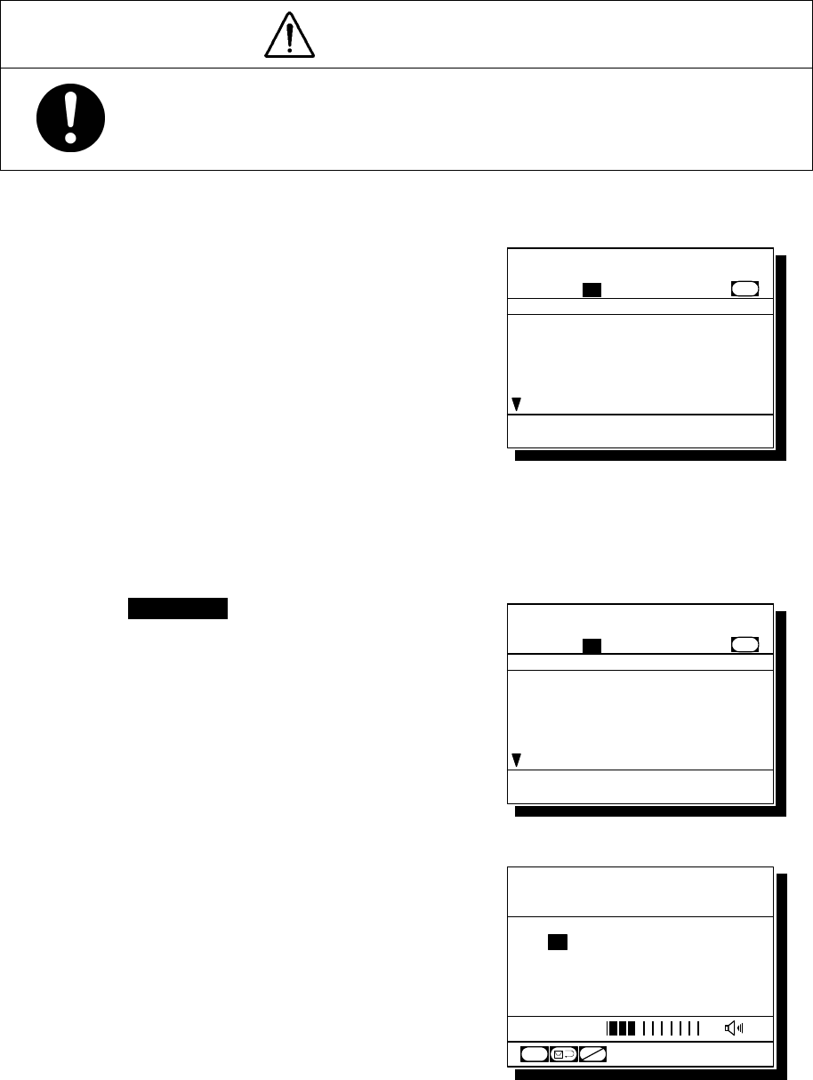
Operation
4-42
4.4.3.3 Receiving a distress call
When a distress call is received, the message will be immediately displayed with the specific two-tone
alarm sound identical to the urgency.
WARNING
If a distress call is received, make sure to inform the ship's captain or officer in
charge.
Doing so may save the lives of the crew and passengers on the ship in distress.
■ Procedure ■
1
1
1.
.
.
When a distress call is received, the
distress message will be displayed.
The alarm lamp will blink in sync with the alarm
sound, gradually growing louder. The example
message contains the following information.
- Type: Distress call
- Caller’s MMSI: 431001234
- Nature of distress: Fire, explosion
-
Position & the time:
North latitude 12º 34.5678'
East longitude 123º 45.6789'
12:14
- EOS: End of sequence
(appears by scrolling)
2
2
2.
.
.
Press the CANCEL key to stop the
alarm, and the screen at right will be
displayed.
3
3
3.
.
.
Select "OK/CH16 watch” with the jog dial
and press ENT to watch on CH16.
Keep watch for at least 5 minutes and, if
necessary, notify a coast station or concerned
administration.
Station1 TIME 23:59(UTC)
POS 89゚59'S
EXT 179゚59'W
16
CH
SQL
CH70
CH
SW
[ITU]
Received distress message
Type :Distress.......
From :431001234......
Nature :Fire...........
Position :12゚34.5678'N...
123゚45.6789'E..
UTC :12:14..........
Station1 TIME 23:59(UTC)
16
CH70
Press CANCEL to silence alarm.
CH [ITU]
Received distress message
Type :Distress.......
From :431001234......
Nature :Fire...........
Position :12゚34.5678'N...
123゚45.6789'E..
UTC :12:14..........
Station1 TIME 23:59(UTC)
16
CH70
[OK/CH16 watch] [Cancel]
CH [ITU]
Operation
4-43
4.4.3.4 Acknowledgement to a received distress call
After receiving a distress call, ship stations have to watch on CH16. But if received the distress call
repeatedly, ship stations (inc. own ship) are allowed to transmit a DSC acknowledgement to terminate
the call only after consulting with an RCC or a coast station and being directed to do so.
■ Procedure ■
1
1
1.
.
.
Press the MENU key, and through
hierarchical menus, select the 4.1 Received
distress list.
On the bottom line, the MMSI of the ship
highlighted by the cursor will be displayed.
2
2
2.
.
.
Select the call to be acknowledged and
press ENT.
The distress message will be displayed.
3
3
3.
.
.
Select ACK with the jog dial and press ENT.
The popup message at right will be displayed.
4
4
4.
.
.
After confirmed the popup message, select
"Continue" and press ENT to send the
acknowledgement.
After the transmission, the channel will be set
to 16 automatically.
After sending the acknowledgement,
commence the distress traffic via
radiotelephony on CH16.
z "MAYDAY"
z Repeat the 9-digit identity (MMSI) of the ship in
distress, 3 times.
z "this is"
z Repeat own ship’s 9-digit identity (MMSI), 3 times.
z ""RECEIVED MAYDAY"
Note
4.1)Received distress list
Date/Time Type
'06-12-31 11:20 Distress
From: 431012345
Station1 TIME 23:59(UTC)
POS 89゚59'S
EXT 179゚59'W
16
CH
SQL
CH70
CHSW
[ITU]
Received distress message
Type :Distress
From :431012345
Nature :Fire
Position :34゚00.1234'S
140゚00.1234'W
UTC :11:20
[Close] [ACK] [Relay]
Received distress message
From :431001234
Nature :Fire
Position :34゚00.1234'S
140゚00.1234'W
UTC :14:55
EOS :EOS
[Close] [ACK] [Relay]
- Attention ! -
Send this call only
when being directed
by administration.
[Continue] [Cancel]
Operation
4-44
4.4.4 Distress relay calls on behalf of someone else (Proxy distress calls)
If another ship is in distress but itself unable to make a distress call, and the master of the ship
considers that further help is necessary, the distress relay call on behalf of the ship can be transmitted
using "Proxy distress call" menu. In this case, compose a distress relay call format by inputting the
MMSI (if known), the ship's position and the time of position (if known), and the nature of distress to
send to all ships or a coast station.
CAUTION
When sending a proxy distress call (DROBOSE), do NOT press the DISTRESS key.
Doing so will inconvenience local shipping and Rescue Centers.
(This proxy distress call can be sent via [Call] button displayed on the screen.)
4.4.4.1 All ships calls
Transmits a proxy distress call (DROBOSE) to all ships.
■ Procedure ■
1
1
1.
.
.
Press the MENU key, and through
hierarchical menus, select 2.4.1 All ships
call.
2
2
2.
.
.
If the 9-digit identity (MMSI) of the ship in
distress is known, press ENT and input it.
If unknown, move the cursor to Nature with the
jog dial and skip to step 4 below.
3
3
3.
.
.
Press ENT.
The cursor will move to Nature.
2.4.1)All ships call
Type :Proxy distress
Dist-ID :[ ]
Nature :[Fire ]
Position:[NE]
[ ゚ . ' ]
[ ゚ . ' ]
UTC :[ : ]
[ OK ] [Cancel]
2.4.1)All ships call
Type :Proxy distress
Dist-ID :[123456789]
Nature :[Fire ]
Position:[NE]
[ ゚ . ' ]
[ ゚ . ' ]
UTC :[ : ]
[ OK ] [Cancel]
2.4.1)All ships call
Type :Proxy distress
Dist-ID :[0 ]
Nature :[Fire ]
Position:[NE]
[ ゚ . ' ]
[ ゚ . ' ]
UTC :[ : ]
[ OK ] [Cancel]
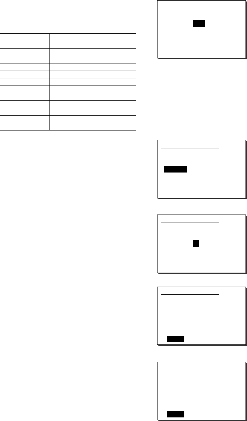
Operation
4-45
4
4
4.
.
.
Press ENT and select the nature of distress
with the jog dial.
The nature of distress is selectable from below.
Nature of distress Contents
Fire Fire, explosion
Flooding Flooding
Collision Collision
Grounding Grounding
Listing Listing, in danger of capsizing
Sinking Sinking
Disabled Disabled and adrift
Undesignated Undesignated distress
Abandoning Abandoning ship
Piracy attack Piracy/armed robbery attack
Man overboard Man overboard
EPIRB emission Received DSC VHF EPIRB signal
5
5
5.
.
.
Press ENT.
The cursor will move to Position.
6
6
6.
.
.
If the position and the time of position of the
ship in distress are known, press ENT.
If unknown, move the cursor to OK with the jog
dial and skip to step 8 below.
7
7
7.
.
.
Input the quadrant, latitude, longitude
and the time of position, respectively and
press ENT.
The cursor will move to OK.
8
8
8.
.
.
Press ENT.
The sending confirmation screen will appear.
Further, unregistered items will be indicated as
"Unknown".
2.4.1)All ships call
Type :Proxy distress
Dist-ID :[123456789]
Nature :[Fire ]
Position:[NE]
[ ゚ . ' ]
[ ゚ . ' ]
UTC :[ : ]
[ OK ] [Cancel]
2.4.1)All ships call
Type :Proxy distress
Dist-ID :[123456789]
Nature :[Fire ]
Position:[NE]
[ ゚ . ' ]
[ ゚ . ' ]
UTC :[ : ]
[ OK ] [Cancel]
2.4.1)All ships call
Type :Proxy distress
Dist-ID :[123456789]
Nature :[Fire ]
Position:[NE]
[ ゚ . ' ]
[ ゚ . ' ]
UTC :[ : ]
[ OK ] [Cancel]
2.4.1)All ships call
Type :Proxy distress
Dist-ID :[123456789]
Nature :[Fire ]
Position:[NE]
[ 12゚34.5678'N]
[123゚45.6789'E]
UTC :[12:20]
[ OK ] [Cancel]
2.4.1)All ships call
Type :Proxy distress
Dist-ID :123456789
Nature :Fire
Position :12゚34.5678'N
123゚45.6789'E
UTC :12:20
[Call] [Cancel]
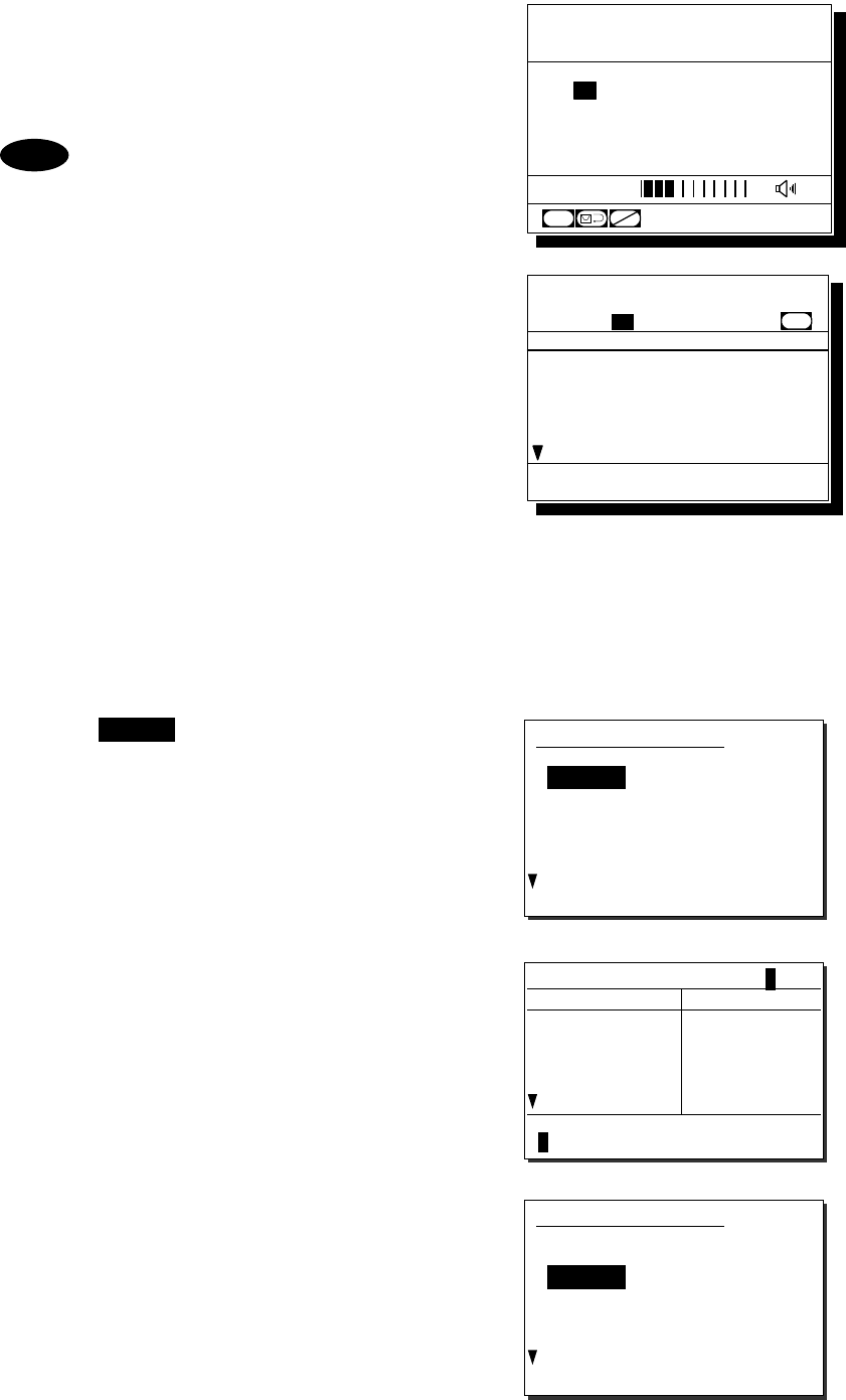
Operation
4-46
9
9
9.
.
.
Press ENT to transmit the call.
Watch on CH16 and wait for the acknowledgement.
After acknowledged, commence the distress traffic
regarding the ship in distress.
- When acknowledged from a coast
station via DSC, the screen at right
(lower) will be displayed and the
specific alarm will sound growing
louder gradually.
- The ALM lamp blinks in sync with the
alarm sound.
- As a general rule, ship stations are
allowed to acknowledge only by the
radiotelephone.
4.4.4.2 Coast station calls
Transmits a proxy distress call (DROBOSE) to a specified coast station.
■ Procedure ■
1
1
1.
.
.
Press the MENU key, and through
hierarchical menus, select 2.4.2 Coast
station call.
2
2
2.
.
.
Press ENT to display the coast station
list, and select the desired station with
the jog dial.
The procedure is identical to the case of the
routine calls.
3
3
3.
.
.
Pressing ENT will move the cursor to
Dist-ID. If the 9-digit identity (MMSI) of
the ship in distress is known, press ENT
and input it.
If unknown, move the cursor to Nature with the
jog dial and skip to step 5 below.
Note
Station1 TIME 23:59(UTC)
POS 89゚59'S
EXT 179゚59'W
16
CH
SQL
CH70
CHSW
[ITU]
2.4.2)Coast station
Type :Proxy distress
Address :[00 ]
Dist-ID :[ ]
Nature :[Undesignated ]
Position:[NE]
[ ゚ . ' ]
[ ゚ . ' ]
[ OK ] [Cancel]
2.4.2)Coast station
Type :Proxy distress
Address :[001011111]
Dist-ID :[ ]
Nature :[Undesignated ]
Position:[NE]
[ ゚ . ' ]
[ ゚ . ' ]
[ OK ] [Cancel]
Coast station list [A]
NAME MMSI
Argentina 001234567
Australia
Azerbaijan
Bolivia
Bangladesh
002222222
003333333
004444444
005555555
Select the initial of the name.
ABCDEFGHIJKLMNOPQRSTUVWXYZ
Received distress message
Type :Proxy dist-ACK.
To :All ships......
From :001011111......
Dist-ID :987654321......
Nature :Fire...........
Position :12゚34.5678'N...
Station1 TIME 23:59(UTC)
16
CH70
Press CANCEL to silence alarm.
CH [ITU]
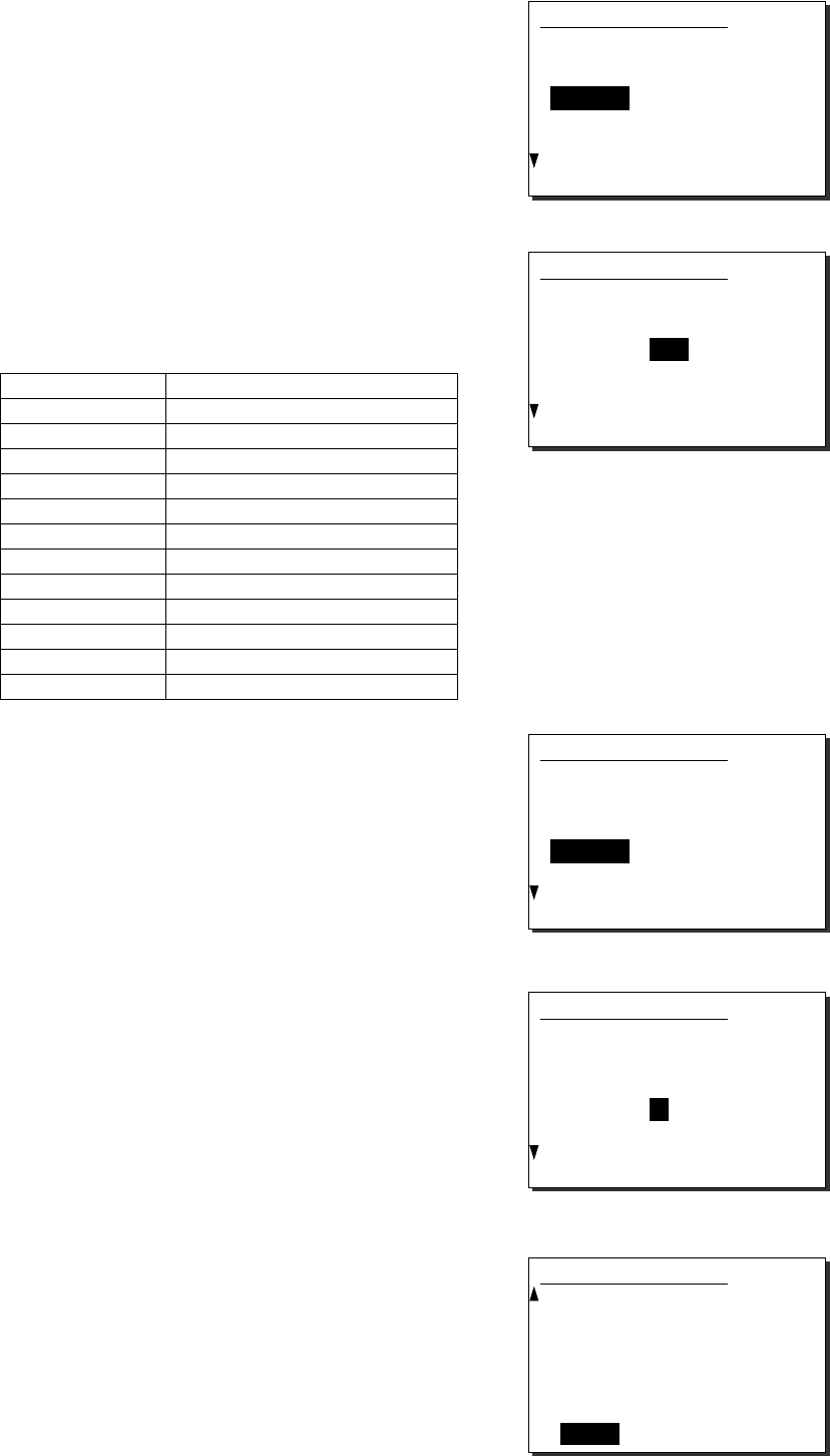
Operation
4-47
4
4
4.
.
.
Press ENT
The cursor will move to Nature.
5
5
5.
.
.
Press ENT and select the nature of distress
with the jog dial.
The nature of distress is selectable from below.
Nature of distress Contents
Fire Fire, explosion
Flooding Flooding
Collision Collision
Grounding Grounding
Listing Listing, in danger of capsizing
Sinking Sinking
Disabled Disabled and adrift
Undesignated Undesignated distress
Abandoning Abandoning ship
Piracy attack Piracy/armed robbery attack
Man overboard Man overboard
EPIRB emission Received DSC VHF EPIRB signal
6
6
6.
.
.
Press ENT.
The cursor will move to Position.
7
7
7.
.
.
If the position and the time of position of the
ship in distress are known, press ENT.
If unknown, move the cursor to OK button with
the jog dial and skip to step 9 below.
8
8
8.
.
.
Input the quadrant, latitude, longitude
and the time of position, respectively and
press ENT.
The cursor will move to OK.
2.4.2)Coast station
Type :Proxy distress
Address :[001011111]
Dist-ID :[987654321]
Nature :[Undesignated ]
Position:[NE]
[ ゚ . ' ]
[ ゚ . ' ]
[ OK ] [Cancel]
2.4.2)Coast station
Type :Proxy distress
Address :[001011111]
Dist-ID :[987654321]
Nature :[Fire ]
Position:[NE]
[ ゚ . ' ]
[ ゚ . ' ]
[ OK ] [Cancel]
2.4.2)Coast station
Address :[001011111]
Dist-ID :[987654321]
Nature :[Fire ]
Position:[NE]
[ 12゚34.5678'N]
[123゚45.6789'E]
UTC :[12:20]
[ OK ] [Cancel]
2.4.2)Coast station
Type :Proxy distress
Address :[001011111]
Dist-ID :[987654321]
Nature :[Fire ]
Position:[NE]
[ ゚ . ' ]
[ ゚ . ' ]
[ OK ] [Cancel]
2.4.2)Coast station
Type :Proxy distress
Address :[001011111]
Dist-ID :[987654321]
Nature :[Fire ]
Position:[NE]
[ ゚ . ' ]
[ ゚ . ' ]
[ OK ] [Cancel]
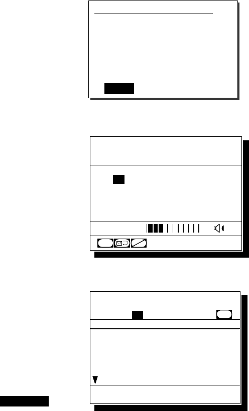
Operation
4-48
9
9
9.
.
.
Press ENT.
The sending confirmation screen will appear.
Further, unregistered items will be indicated as
"Unknown".
1
1
10
0
0.
.
.
Press ENT to transmit the call.
Watch on CH16 and wait for the acknowledgement.
1
1
11
1
1.
.
.
When acknowledged, the screen at right
will be displayed and the alarm will sound
growing louder gradually.
Then lift the handset and commence
distress traffic for the ship in distress.
¾ The ALM lamp blinks in sync with the alarm sound.
¾ Only to silence the alarm, press the CANCEL
key when displaying the screen at right.
2.4.2)Coast station call
Type :Proxy distress
Address :001011111
Dist-ID :987654321
Nature :Fire
Position :12゚34.5678'N
123゚45.6789'E
UTC :12:20
[Call] [Cancel]
Station1 TIME 23:59(UTC)
POS 89゚59'S
EXT 179゚59'W
16
CH
SQL
CH70
CHSW
[ITU]
Received distress message
Type :Proxy dist-ACK.
To :Individual.....
From :001011111......
Dist-ID :987654321......
Nature :Fire...........
Position :12゚34.5678'N...
Station1 TIME 23:59(UTC)
16
CH70
Press CANCEL to silence alarm.
CH [ITU]
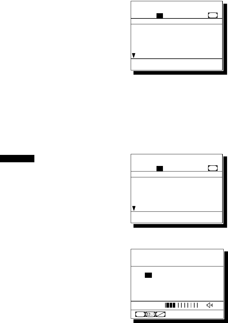
Operation
4-49
4.4.4.3 Receiving a proxy distress call
When received a distress relay call (DROBOSE) directed to all ships, the ship stations (inc. your own
ship) are allowed to acknowledge only by the radiotelephone. (Receiving a distress relay call from a
coast station is the same.)
■ Procedure ■
1
1
1.
.
.
When received a proxy distress call, the
screen at right will be displayed.
¾ The specific alarm will sound growing louder
gradually.
¾ The ALM lamp blinks in sync with the alarm sound.
¾ The example message contains the following
information.
- Type: Proxy distress call
- To: All ships
- Caller’s MMSI: 123456789
- MMSI of ship in distress: 987654321
- Nature of distress: Fire, explosion
- Position and Time: North latitude 12º 34.5678'
(Longitude and the time appears by scrolling.)
- EOS: ACK is requested.
(appears by scrolling)
2
2
2.
.
.
Press the CANCEL key to stop the
alarm, and the screen at right will be
displayed.
3
3
3.
.
.
Select OK/CH16 watch with the jog dial
and press ENT then watch on CH16.
Keep watch for at least 5 minutes and, if
necessary, notify a coast station or concerned
administration via radiotelephony.
Station1 TIME 23:59(UTC)
POS 89゚59'S
EXT 179゚59'W
16
CH
SQL
CH70
CHSW
[ITU]
Received distress message
Type :Proxy distress.
To :All ships......
From :123456789......
Dist-ID :987654321......
Nature :Fire...........
Position :12゚34.5678'N...
Station1 TIME 23:59(UTC)
16
CH70
Press CANCEL to silence alarm.
CH [ITU]
Received distress message
Type :Proxy distress.
To :All ships......
From :123456789......
Dist-ID :987654321......
Nature :Fire...........
Position :12゚34.5678'N...
Station1 TIME 23:59(UTC)
16
CH70
[OK/CH16 watch] [Cancel]
CH [ITU]
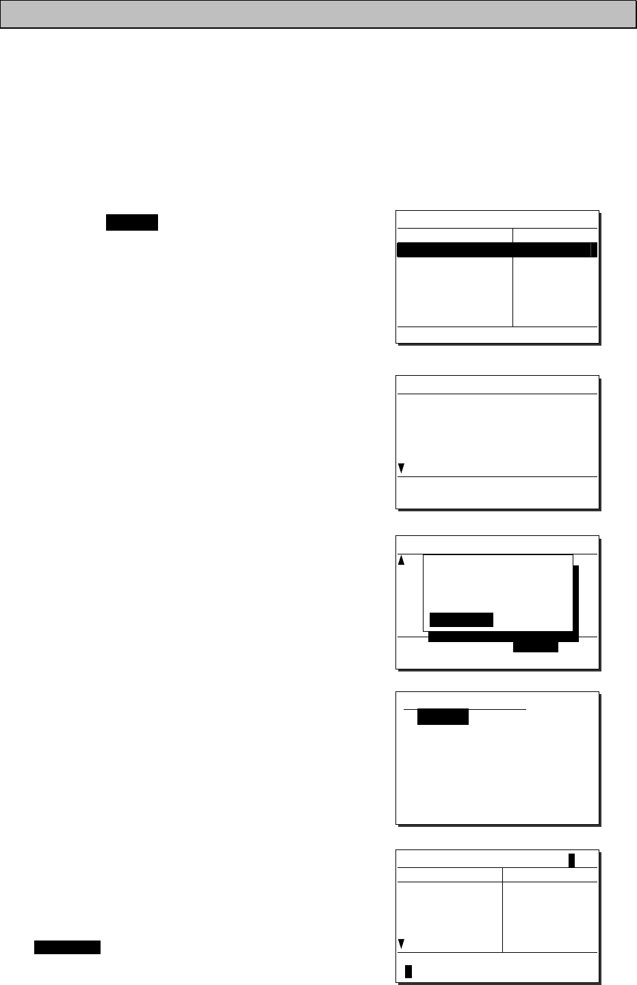
Operation
4-50
4.4.5 Distress relay calls
After receiving a distress call, ship stations have to watch on CH16 for at least 5 minutes. But if there
is no distress traffic on CH16 in the meantime, the distress relay call will be available to inform a coast
station of the distress call transmitted by the ship in distress.
4.4.5.1 Sending a distress relay call
A distress relay call can be composed from the log of the received distress message.
■ Procedure ■
1
1
1.
.
.
Press the MENU key, and through
hierarchical menus, select the 4.1 Received
distress list.
On the bottom line, the MMSI of the ship
highlighted by the cursor will be displayed.
2
2
2.
.
.
Select the distress call to be relayed and
press ENT.
The distress message will be displayed.
3
3
3.
.
.
Select Relay with the jog dial and press ENT.
The popup message at right will be displayed.
4
4
4.
.
.
After confirmed the popup message,
select "Continue" and press ENT.
The address inputting screen will be displayed.
5
5
5.
.
.
Press ENT to display the station list of both
the coast stations and the ship stations, and
select the desired station with the jog dial.
When inputting the MMSI manually, press the
CANCEL key to return to the previous screen
and input it using the numeric keypad.
4.1)Received distress list
Date/Time Type
'06-12-31 14:55 Distress
From: 987654321
Distress relay call
Address :[ ]
[ OK ] [Cancel]
Received distress message
Type :Distress
From :987654321
Nature :Fire
Position :34゚00.1234'N
140゚00.1234'E
UTC :14:55
[Close] [ACK] [Relay]
Received distress message
From :431001234
Nature :Fire
Position :34゚00.1234'S
140゚00.1234'W
UTC :14:55
EOS :EOS
[Close] [ACK] [Relay]
- Attention ! -
Normally, this call
should be sent to
coast station.
[Continue] [Cancel]
Station list
[A]
NAME MMSI
Argentina 001234567
Australia
Azerbaijan
Bolivia
Bangladesh
002222222
003333333
004444444
005555555
Select the initial of the name.
ABCDEFGHIJKLMNOPQRSTUVWXYZ
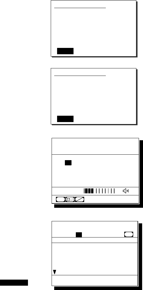
Operation
4-51
6
6
6.
.
.
Press ENT.
The cursor will move to OK.
7
7
7.
.
.
Press ENT.
The sending confirmation screen will appear.
8
8
8.
.
.
Press ENT to send the distress relay call.
After the transmission, the channel will be set
to 16 automatically.
9
9
9.
.
.
When acknowledged, the screen at right will
be displayed and the alarm will sound
growing louder gradually. Then lift the
handset and commence distress traffic for
the ship in distress.
¾ The ALM lamp blinks in sync with the alarm sound.
¾ Only to silence the alarm, press the CANCEL
key when displaying the screen at right.
Distress relay call
Address :[001011111]
[ OK ] [Cancel]
Distress relay call
Address :001011111
[Call] [Cancel]
Station1 TIME 23:59(UTC)
POS 89゚59'S
EXT 179゚59'W
16
CH
SQL
CH70
CHSW
[ITU]
Received distress message
Type :Dist-relay ACK.
To :Individual.....
From :001011111......
Dist-ID :987654321......
Nature :Fire...........
Position :34゚00.1234'N...
Station1 TIME 23:59(UTC)
16
CH70
Press CANCEL to silence alarm.
CH [ITU]
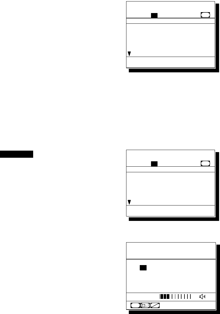
Operation
4-52
4.4.5.2 Receiving a distress relay call
Normally, ship stations receive a distress relay call in the following situations.
・ When a coast station has transmitted an all ships or individual distress relay call.
・ When another ship station has transmitted a distress relay call to all ships, an individual
distress relay call, or a geographic distress relay call to a specific sea area.
As a general rule, the ship stations should respond via radiotelephony after receiving a distress relay
call. But if called individually by another ship station, and if allowed by a coast station, a distress
relay acknowledgement can be transmitted as follows. Further, a distress relay acknowledgement can
be composed from the log of the received distress relay message.
■ Procedure ■
1
1
1.
.
.
When a distress relay call is received,
the screen at right will be displayed.
¾ The specific alarm will sound growing louder
gradually.
¾ The ALM lamp blinks in sync with the alarm sound.
¾ The example message contains the following
information.
- Type: Distress relay call
- To: Individual (own ship)
- Caller’s MMSI: 123456789
- MMSI of ship in Distress: 987654321
- Nature of distress: Fire, explosion
- Position and Time: North latitude 34º 00.1234'
(Longitude and the time appears by scrolling.)
- EOS: ACK is requested.
(appears by scrolling)
2
2
2.
.
.
Press the CANCEL key to stop the
alarm, and the screen at right will be
displayed.
3
3
3.
.
.
Select OK/CH16 watch with the jog dial
and press ENT then watch on CH16.
¾ Keep watch for at least 5 minutes.
¾ When acknowledging the distress relay,
follow the procedure described below.
Station1 TIME 23:59(UTC)
POS 89゚59'S
EXT 179゚59'W
16
CH
SQL
CH70
CHSW
[ITU]
Received distress message
Type :Distress relay.
To :Individual.....
From :123456789......
Dist-ID :987654321......
Nature :Fire...........
Position :34゚00.1234'N...
Station1 TIME 23:59(UTC)
16
CH70
Press CANCEL to silence alarm.
CH [ITU]
Received distress message
Type :Distress relay.
To :Individual.....
From :123456789......
Dist-ID :987654321......
Nature :Fire...........
Position :34゚00.1234'N...
Station1 TIME 23:59(UTC)
16
CH70
[OK/CH16 watch] [Cancel]
CH [ITU]
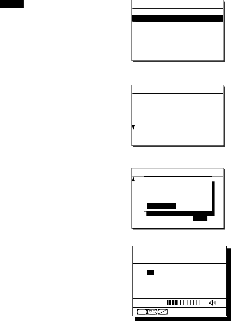
Operation
4-53
4
4
4.
.
.
Press the MENU key, and through
hierarchical menus, select the 4.1 Received
distress list.
On the bottom line, the MMSI of the ship
highlighted by the cursor will be displayed.
5
5
5.
.
.
Select the distress relay call to be
acknowledged and press ENT.
The distress relay message will be displayed.
6
6
6.
.
.
Select ACK with the jog dial, and press ENT.
The popup message at right will be displayed.
7
7
7.
.
.
After confirmed the popup message,
select "Continue" and press ENT to send
the distress relay acknowledgement.
After the transmission, the channel will be set
to 16 automatically. Then wait for a call via
radiotelephony on that channel.
4.1)Received distress list
Date/Time Type
'06-01-10 08:45 Relay
From: 123456789
Station1 TIME 23:59(UTC)
POS 89゚59'S
EXT 179゚59'W
16
CH
SQL
CH70
CHSW
[ITU]
Received distress message
Type :Distress relay
To :Individual
From :123456789
Dist-ID :987654321
Nature :Fire
Position :34゚00.1234'N
[Close] [ACK]
Received distress message
Dist-ID :987654321
Nature :Fire
Position :34゚00.1234'N
124゚00.5678'E
UTC :12:12
EOS :ACK RQ
[Close] [ACK]
- Attention ! -
Send this call only
when being directed
by administration.
[Continue] [Cancel]
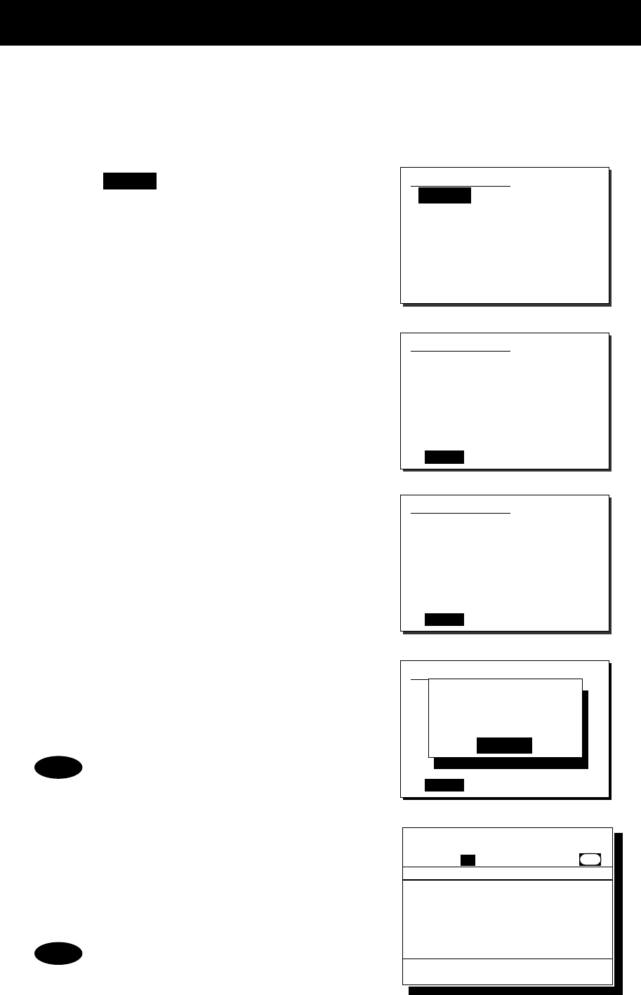
Operation
4-54
4.5 Simple DSC test call
The following describes simple procedure to send a DSC test call from the dedicated menu.
(Note: This menu is prepared to simplify the test call procedure in the menu 2.1.2 Specific station,
and both of the message formats are exactly the same.)
■ Procedure ■
1
1
1.
.
.
Press the MENU key, and through
hierarchical menus, select the 3. DSC test
call.
The address inputting screen will be displayed.
If entered previously, the address will be
appeared as a default value.
2
2
2.
.
.
Input the desired station's MMSI and
press ENT.
The procedure is identical to the case of an
individual call for safety. (The list shows ship
stations first, and then coast stations.)
3
3
3.
.
.
If the contents are correct, press ENT.
The sending confirmation screen will appear.
4
4
4.
.
.
Press ENT to transmit the call.
After completed the transmission, the popup
screen shown at right will be displayed to wait
the acknowledgement.
If received no response for 5 minutes,
the screen will return to the step 1
mentioned above.
5
5
5.
.
.
When received the acknowledgement,
the screen shows the message with the
alarm as shown at right.
Pressing CANCEL stops alarm and after that,
pressing ENT returns to the status display.
According to the condition of the station,
the acknowledgement may not be received
even if the equipment works normally.
3)DSC test call
Address :[123456789]
[
OK
]
[
Cancel
]
Note
Note
3)DSC test call
Address :[123456789]
[
OK
]
[
Cancel
]
3)DSC test call
Address :123456789
[
Call
]
[
Cancel
]
3)DSC test call
Address :234567890
[
Call
]
[
Cancel
]
Waiting for
Acknowledgement.
[Cancel]
Received safety message
Format :Individual ACK
From :123456789......
Type :Test...........
EOS :ACK BQ.........
Station1 TIME 23:59(UTC)
16
CH70
Press CANCEL to silence alarm.
CH [ITU]
Operation
4-55
4.6 DSC call log
Received DSC messages are classified as distress messages and as other messages. The 20 most
recent messages for both types of received and transmitted are saved in the log.
CAUTION
A distress acknowledgement or a distress relay call can be transmitted from a
received distress message stored in the log, but when sending such a kind of call,
follow the instructions of the ship's captain or officer in charge.
Received distress calls are automatically deleted after 48 hours to avoid accidental
resending or other misoperation. Accordingly, if such messages cannot be read
out, it is not a malfunction.
4.6.1 Received distress messages
Received messages regarding distress calls and the acknowledgements, distress relay calls and the
acknowledgements will be displayed in this received distress message log. Additionally, when
receiving a distress call containing the same 5 messages, only one of those will be stored.
■ Procedure ■
1
1
1.
.
.
Press the MENU key, and through
hierarchical menus, select the 4.1 Received
distress list.
¾ On the bottom line, the MMSI of the ship
highlighted by the cursor will be displayed.
¾ In the event of a receiving error (ECC error),
"ECC error" will be indicated in the Type field.
2
2
2.
.
.
To view a message, select a line by timestamp
and/or message type, and press ENT.
The selected message will be displayed.
Also the screen shows Message handling menus
at the bottom of the screen and enabled to handle
the message as follows.
(The handling menus will differ depending on the
type of message .)
- Close: Close the message and return to the list.
- ACK: Send the acknowledgement to the caller.
(In this case, to the ship in distress)
- Relay: Send this message to a specified coast
station as a distress relay call.
4.1)Received distress list
Date/Time Type
'06-12-31 11:20 ACK
'06-12-31 11:15
'06-12-31 11:10
'06-12-30 08:55
Relay-ACK
Distress
Relay
From: 431012345
Received distress message
Type :Distress
From :987654321
Nature :Fire
Position :34゚00.1234'S
140゚00.1234'W
UTC :14:55
[Close] [ACK] [Relay]
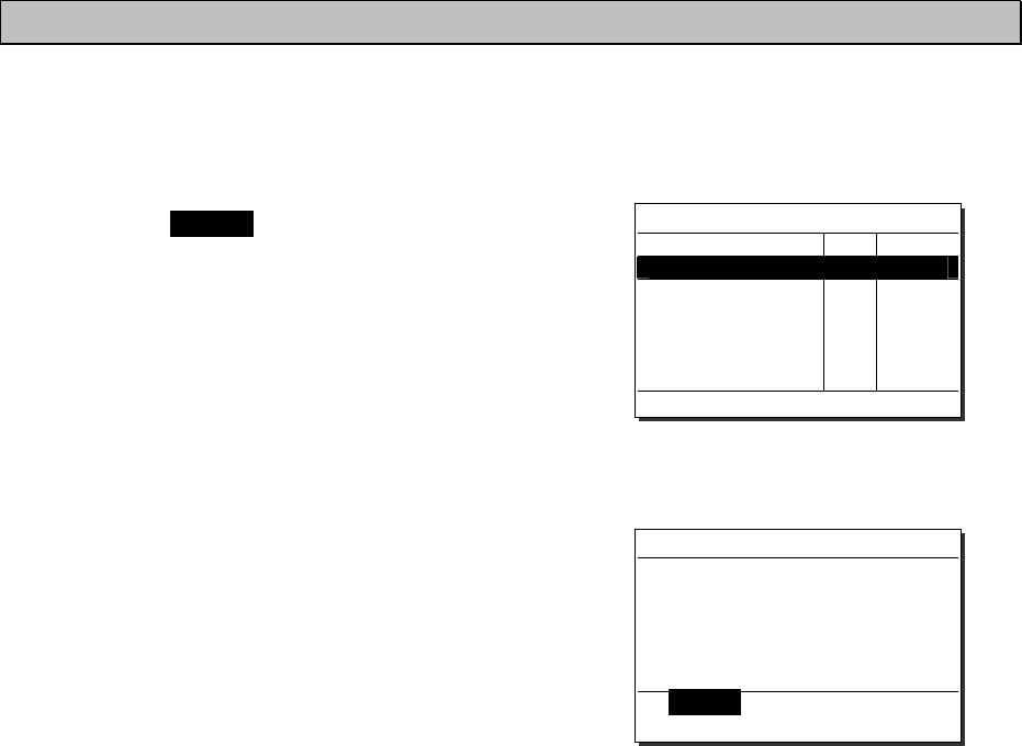
Operation
4-56
4.6.2 Received other messages
Received messages regarding routine, safety, and urgency calls or the acknowledgements will be
displayed in this received other message log.
■ Procedure ■
1
1
1.
.
.
Press the MENU key, and through
hierarchical menus, select the 4.2 Received
others list.
¾ On the bottom line, the MMSI of the ship
highlighted by the cursor will be displayed.
¾ In the event of a receiving error (ECC error),
"ERR" will be indicated in the CAT field.
(Note: CAT: category, FMT: format)
2
2
2.
.
.
To view a message, select a line by timestamp,
category and/or format, and press ENT.
The selected message will be displayed.
Also the screen shows Message handling menus
at the bottom of the screen and enabled to handle
the message as follows.
(The handling menus will differ depending on the
type of message .)
- Close: Close the message and return to the list.
- ACK: Send the acknowledgement to the caller.
- NACK: Send a negative acknowledgement with
the reason to the caller.
- New CH: Send the acknowledgement with another
working channel proposal.
- MMSI: Register the caller's ID.
(The corresponding menu such as 9.4.1
Coast station list will be opened.)
- TEL No: Register the PSTN caller's or recipient's
telephone number.
(Menu 9.4.4 PSTN number list will be
- opened.)
4.2)Received others list
Date/Time CAT FMT
'06-11-23 15:30 RTN INDIV
'06-11-20 22:15
'06-11-19 07:10
'06-11-15 18:33
URG
SAF
RTN
ACK
ALL
GRP
From: 123456789
Received routine message
Format :Individual call
From :123456789
Type :All modes RT
Work CH :10
EOS :ACK RQ
[Close] [ACK] [NACK]
[New CH] [MMSI]
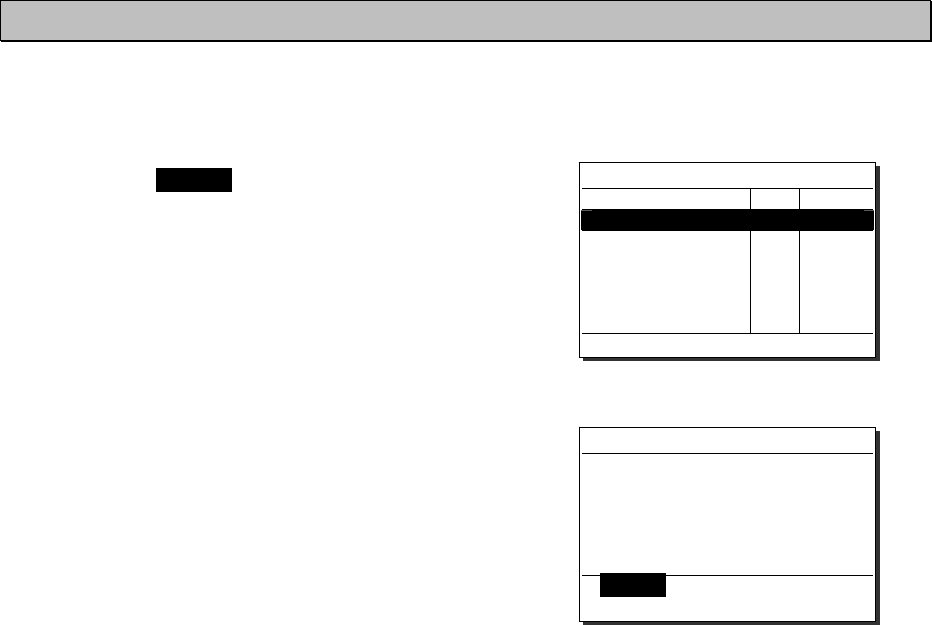
Operation
4-57
4.6.3 Transmitted messages
Every transmitted message will be displayed in this transmitted message log.
■ Procedure ■
1
1
1.
.
.
Press the MENU key, and through
hierarchical menus, select the 4.3
Transmitted calls list.
On the bottom line, the address information
(such as MMSI) of the line highlighted by the
cursor will be displayed.
2
2
2.
.
.
To view a message, select a line by timestamp,
category and/or format, and press ENT.
The selected message will be displayed.
Also the screen shows Message handling menus
at the bottom of the screen and enabled to handle
the message as follows.
(The handling menus will differ depending on the
type of message .)
- Close: Close the message and return to the list.
- Resend: Resend this message to the same address.
-
Edit&Send
: Make a new call after revising based on
the message.
4.3)Transmitted calls list
Date/Time CAT FMT
'06-01-23 12:30 RTN INDIV
'06-12-15 20:15
'06-12-13 18:10
'06-11-20 06:33
'06-11-18 08:45
URG
SAF
RTN
RTN
ACK
ALL
GRP
INDIV
To: 123456789
Transmitted routine message
Format :Individual call
To :123456789
Type :All modes RT
Work CH :10
[Close] [Resend] [Edit&Send]
Operation
4-58
4.7 Other features
In addition to the features described above, the equipment contains useful some features as below.
4.7.1 Notification of registered ships by the AIS
If the AIS have been installed and set to available by the following procedure (and the menu 9.6 AIS
function), when ships registered in the contact list falls within the specified range, a popup screen will
be displayed immediately and notifies the ship's information by the name or 9-digit identity (MMSI).
■ Procedure ■
1
1
1.
.
.
Press the MENU key, and through
hierarchical menus, select the 5. AIS
information.
The example at right shows the factory
default setting.
2
2
2.
.
.
To activate this function, select the line of
2. Rgst ships check, and after pressing ENT,
set the condition to ON with the jog dial.
3
3
3.
.
.
Press ENT.
If changing the proximity range, after pressing ENT
again, input the appropriate value within the range of
0.1 to 99.9NM with the numeric keypad or jog dial.
4
4
4.
.
.
After completed the proximity range setting,
the cursor will move to the 0. Back.
When detected the registered ship within the
specified proximity range, the popup screen as
shown at right will be appeared immediately.
However, if the AIS information does not
contain the ship's name, the name line will be
replaced by the MMSI number.
5)AIS information
1.Other ships list
2.Proximity check :OFF
tip)Notify of when listed-ship
fall within the range.
3.Proximity range :20.0NM
0.Back
Note
5)AIS information
1.Other ships list
2.Proximity check :ON
tip)Notify of when listed-ship
fall within the range.
3.Proximity range :20.0NM
0.Back
5)AIS information
1.Other ships list
2.Proximity check :OFF
tip)Notify of when listed-ship
fall within the range.
3.Proximity range :20.0NM
0.Back
5)AIS information
1.Other ships list
2.Proximity check :OFF
tip)Notify of when listed-ship
fall within the range.
3.Proximity range :20.0NM
0.Back
Note
Operation
4-59
4.7.2 Playback of received voice
When opened the squelch, incoming voice will be automatically recorded (up to 120 seconds), and can
be replayed to confirm voice communications. Recorded voice is divided into multiple tracks
depending on the time for the squelch open/close, and will remain stored until power off. If the total
recorded time of all tracks reaches 120 seconds, recorded tracks will be overwritten beginning with the
oldest one.
(1) Replay and stop operations
■ Procedure ■
1
1
1.
.
.
Press FUNC Î 9
¾ If existing any recorded tracks, replay the
latest track immediately.
¾ Pressing ENT will reset the counter and
restart the playback of the track.
¾ The example at right shows the following.
- Replaying track number: 001
- Total track numbers: 012
- Counter value (elapsed time): 002 seconds
- Recorded time of the track: 035 seconds
2
2
2.
.
.
After finished the playback of the latest track,
the cursor will automatically move to Track
and the function will enter stop mode.
¾ To stop the playback manually, press the
CANCEL key.
¾ If existing other tracks recorded, enabled to select
a track number with the jog dial in stop mode.
¾ To replay beginning with the displayed track to the
latest one, press ENT in stop mode.
¾ To finish this menu, press the CANCEL key in
stop mode.
6.1)Playback
Track : Play FF&REW
001/012 002/035 sec
Control:Turn/push JogDial
Stop
:
Press CANCEL
6.1)Playback
Track : Play FF&REW
001/012 000/035 sec
Track SEL:Turn/push JogDial
Abort menu
:
Press CANCEL
Operation
4-60
(2) Fast forward and rewind operations
During playback, the fast forward or rewind is available by the following procedure.
■ Procedure ■
1
1
1.
.
.
Rotate the jog dial during playback to
move the cursor to FF&REW.
¾ Rotating the jog dial right will perform fast
forward by increasing the counter value.
¾ Rotating the jog dial left will perform rewind
by decreasing the counter value.
¾ To break FF&REW operation, press the CANCEL
key. After that, the playback will resume from
when playback was paused.
2
2
2.
.
.
After FF&REW operation, press ENT to
continue to replay from the counter position.
Further, after 1sec elapsed since the FF&REW
operation, the playback will resume automatically
without pressing ENT.
(3) Temporary track saving
Normally, when the total recorded time of all tracks reaches 120 seconds, new voice track will
overwrite beginning with the oldest track. But if desired to save a track until power off, perform the
procedure below.
■ Procedure ■
1
1
1.
.
.
When the cursor is on Track (stop mode),
select the desired track with the jog dial.
The example at right shows the case of track 1 selected.
Only 1 track can be saved.
2
2
2.
.
.
Press ENT for more than 1 second.
¾ When completed the saving, a beep will sound
and the track number will change from “001”
to "S", as is shown at right.
¾ The saved track is registered as the last number.
In the example at right, the track is saved as No.12.
When completed the saving, the subsequent track numbers will be shifted down by 1.
6.1)Playback
Track : Play FF&REW
001/012 002/008 sec
Control:Turn/push JogDial
Stop
:
Press CANCEL
6.1)Playback
Track : Play FF&REW
001/012 002/020 sec
Control:Turn/push JogDial
Stop
:
Press CANCEL
6.1)Playback
Track : Play FF&REW
001/012 000/035 sec
Track SEL:Turn/push JogDial
Abort menu
:
Press CANCEL
Note
6.1)Playback
Track : Play FF&REW
S /012 000/035 sec
Saved the track as #012.
Track SEL:Turn/push JogDial
Ab
ort menu
:
Press CANCEL
Note
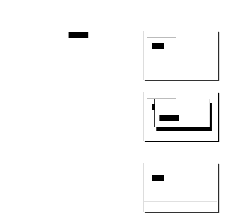
Operation
4-61
(4) The saved track deletion
To delete a saved track, perform the following procedure. (Powering off will delete all tracks.)
■ Procedure ■
1
1
1.
.
.
When the cursor is on Track (stop mode),
select DEL with the jog dial.
2
2
2.
.
.
Press ENT.
A confirmation message will appear.
3
3
3.
.
.
After confirmed the popup message,
select "OK" and press ENT.
After completed the deletion, track 1 will be
selected, as shown at right.
6.1)Playback
Track : Play FF&REW
DEL/012 000/035 sec
Track SEL:Turn/push JogDial
Abort menu
:
Press CANCEL
OK to delete
the saved track?
[ OK ] [Cancel]
6.1)Playback
Track : Play FF&REW
DEL/012 000/035 sec
Track SEL:Turn/push JogDial
Abort menu
:
Press CANCEL
6.1)Playback
Track : Play FF&REW
001/011 000/013 sec
Track SEL:Turn/push JogDial
Abort menu
:
Press CANCEL

Operation
4-62
4.7.3 Public Address function with an external speaker (option)
If an external speaker (NVS-423R) is connected, the Public Address function is available to make an
announcement over the external speaker.
■ Procedure ■
1
1
1.
.
.
Lift the handset from the cradle, and
press FUNC Î 4PA .
¾ The equipment will immediately enter PA mode
and enabled to make an announcement over
the external speaker.
¾ Press PTT key to talk.
¾ To finish the public address function and return
to the status display, place the handset back on
hook.
(Also, pressing the CANCEL key is as well.)
In this mode, radio wave is not transmitted by PTT.
Public Address mode
Note
Operation
4-63
4.7.4 Intercom
If multiple controllers (NCM-1770) are connected, the intercom is available between two of them.
(1) Calling another controller
■ Procedure ■
1
1
1.
.
.
Lift the handset from the cradle, and
press FUNC Î 5 .
¾ The controller list will be displayed.
¾ The example at right shows that the
following controllers are connected.
- Address 1: Station1
- Address 2: Calling controller
- Address 3: Station3
- Address 4: Station4
(Address 5 controller is not connected.)
2
2
2.
.
.
Select a recipient with the jog dial and
press ENT.
¾ The screen at right will be displayed and
the intercom call will start.
¾ To cancel the calling, press the CANCEL
key or hang up the handset while calling.
- If the handset of the recipient has been
left in the off-hook condition, the call
will not start, and the screen shown at
right will be displayed.
Then press ENT to return to the step 1.
- If not answered within 30 seconds, the
screen shown at right will be displayed.
Then press ENT to return to the step 1.
3
3
3.
.
.
After answered the phone, the screen
shown at right will be displayed and
enabled to start the communication.
¾ Press PTT key to talk.
¾ To finish the intercom, place the handset
back on hook.
Intercom mode
State: Time out
[ OK ]
6.3)Intercom
1.Station1
2.(Own station)
3.Station3
4.Station4
5.(N/A)
0.Back
INT
COM
Intercom mode
State: Calling
Intercom mode
State: Connected
Note
Intercom mode
State: Busy
[ OK ]
Operation
4-64
(2) Receiving a call from another controller
■ Procedure ■
1
1
1.
.
.
If received an intercom call, the screen at
right will be displayed, and the ringing tone
will sound.
If not answer within 30 seconds, the screen will
revert to the previous screen.
2
2
2.
.
.
When answering to the call, lift the
handset and start the communication.
¾ Press PTT key to talk.
¾ To finish the intercom, place the handset
back on hook.
- The OCC mark will remain displayed
even while talking, because the called
controller (recipient) is in monitor mode.
- While using the intercom function between
two of controllers, if the other controllers
are connected, those screens will display
as shown at right.
Intercom mode
State: Receiving a call
from: Station2
Intercom mode
State: Connected
Note
Intercom mode
State: Busy

Operation
4-65
4.8 Popup screens
The contents of the popup screens are as follows. (in alphabetical order)
Message Buttons Description
Acknowledged!
Accept it and abort this menu immediately? Accept/ Ignore
Received a DSC acknowledgement
(ACK BQ) during menu operation.
Accept: Closes the menu and shows
the message immediately.
Ignore: Closes this popup only.
Acknowledged!
From: xxxxxxxxx
Shifting CH now...
-----
Received a PSTN acknowledgement
from the coast station (MMSI: xxxxxxxxx),
and the transceiver is shifting to the
specified work channel now.
AIS information
Detected this ship in the vicinity.
MMSI: xxxxxxxxx
OK
Detected the ship (MMSI: xxxxxxxxx) in
the AIS information within the specified
sea area.
AIS information
Detected this ship in the vicinity.
xxxxxxxxxxxxxxxxxxxx
OK
Detected the ship
(named xxxxxxxxxxxxxxxxxxxx)
in the AIS information within the
specified sea area.
Attention!
DSC usage is NOT allowed on Inland
Waterways.
Continue/ Cancel
DSC usage is NOT allowed on Inland
Waterways.
Continue: Enforces the DSC operation.
Cancel: Ceases the DSC operation.
Attention!
Specified a duplex channel used for a coast
station comm.
Continue/ Cancel
When calling a ship or a group by the
DSC, specified a duplex channel as a
work channel, which is used for a coast
station communication.
Continue: Enforces the operation.
Cancel: Ceases the operation.
Attention!
Normally, this call should be sent to a coast
station.
Continue/ Cancel
When sending a distress relay call, it
should be normally addressed to a
coast station.
Continue: Continues the operation.
Cancel: Ceases the operation.
Attention!
Restarting distress call soon... ----- DSC resends the distress call
automatically soon.
Attention!
Send this call only when being directed by
administration.
Continue/ Cancel
To send the distress acknowledgement
or the distress relay acknowledgement,
the consulting with RCC or a coast
station is necessary.
Continue: Continues the operation.
Cancel: Ceases the operation.
Channel connection completed.
Lift handset please. -----
The channel connection via the DSC
has been completed. Please start the
communication using the handset.
Channel dial op is invalid right now.
To enable it, press FUNC, and ENT. -----
The channel operation with the jog dial
is disabled right now. To enable it,
press the FUNC key and ENT in
order.
CHxx SQL Setting
Register or erase the SQL level? REG/ Erase
Register or erase the preset squelch
level of the xx channel.
REG: Registers the current level.
Erase: Erases the preset condition.

Operation
4-66
Coast sta no answer. OK After the PSTN call, there is no answer
from the coast station.
Confirming channel free... Cancel
To send the DSC call (routine calls or
test), confirming if the CH70 is free, or
waiting until the CH70 becomes free.
Data updating... ----- Updating the AIS information.
DISTRESS call starts in Xsec -----
Detected keeping the DISTRESS
key held down, and the distress call will
be sent in X seconds.
DISTRESS pressed by xxxxxxxxxx and starts
in Xsec -----
The DISTRESS key of xxxxxxxxxx
has been held down now, and the
distress call will be sent in X seconds.
Erase all data? OK/ Cancel
Is it ok to erase every station data of
this station list?
OK: Erases all data.
Cancel: Ceases this operation.
Erase this number? OK/ Cancel
Is it ok to erase this station data?
OK: Erases this station data.
Cancel: Ceases this operation.
Invalid address OK The DSC calling address is empty or
invalid.
Invalid TEL number OK The recipient telephone number for a
PSTN call is empty or invalid.
Invalid value OK An invalid value is detected during a
process of a task.
Invalid work CH OK The work channel data for the DSC call
is empty or invalid.
Is it OK to break PSTN mode? OK/ Cancel
Pressed the CANCEL key during
PSTN communication mode. Is it ok to
break?
OK: Breaks the PSTN mode.
Cancel: Continues the PSTN mode.
Left without operating...
This process will be canceled soon. -----
This process will be canceled in 1 min
and returns to the status display
condition because the controller has
been left for 9 min without operating.
Lost the radio receiving signal. OK
Lost the carrier receiving at the work
channel during the PSTN mode, and
breaks the communication.
No signal detected in the Work-CH. OK
The transceiver shifted to the specified
work channel to start the PSTN
communication, but cannot detect the
carrier from the coast station.
Now continuing DISTRESS call mode.
Break this mode? Continue/ Break
Pressed the CANCEL key during the
distress call mode. Is it ok to break?
Continue: Continues the distress mode.
Break: Breaks the distress mode.
OK to "sleep" this no access right controller? Sleep/ Cancel
Pressed the DIM + PWR keys at
this controller without the access rights.
Is it ok to enter the sleep mode?
Sleep: Enters the sleep mode.
Cancel: Ceases this operation.

Operation
4-67
OK to clear SQL of all xxx CH? OK/ Cancel
Is it ok to clear every preset squelch
data of the xxx channel mode?
OK: Erases all preset SQL data.
Cancel: Ceases this operation.
OK to delete the saved track? OK/ Cancel
Is it ok to delete the saved track where
the recorded voice has been saved
temporally?
OK: Deletes the saved track.
Cancel: Ceases this operation.
OK to overwrite? OK/ Cancel
Is it ok to overwrite the caller's MMSI
on the specified line number where
another station has been registered?
OK: Overwrites it on the line.
Cancel: Ceases this operation.
OK to power off the VHF system? OK/ Sleep/ Cancel
Pressed the DIM + PWR keys at
this controller with the access right.
OK: Turns off the power.
Sleep: Enters the sleep mode.
Cancel: Ceases this operation.
Press ENT to stop the sound. -----
Testing the internal loudspeaker now.
After checking the sound, press ENT to
stop it.
Print out this data? OK/ Cancel
Print out the displaying data?
OK: Prints out now.
Cancel: Ceases this operation.
Printing now... Cancel Printing out the displaying data.
Wait a moment.
Received DISTRESS.
Accept it and abort this menu immediately? Accept/ Ignore
Received the DSC distress call during
menu operation. Is it ok to abort the
current process to view the message?
Accept: Breaks the current process to
view the distress message.
Ignore: Closes the popup only.
Received DSC call.
Accept it and abort this menu immediately? Accept/ Ignore
Received the DSC call during menu
operation. Is it ok to abort the current
process to view the message?
Accept: Breaks the current process to
view the DSC message.
Ignore: Closes the popup only.
Received other call.
Break DISTRESS mode to view message? Continue/ Break
Received the DSC call during distress
mode. Break this mode to view the
message now?
Continue: Continues the distress mode.
Break: Breaks the distress mode.
Received PSTN call from a coast sta.
And now setting the PSTN mode... -----
Received a PSTN call from a coast
station and setting the PSTN mode.
Wait a moment.
Remaining the field maintenance mode.
Please restart after maintenance. OK Equipment is left in the field
maintenance mode. Please restart.
Required to input position & time.
Accept it now? Accept/ Ignore
The external position fixing device (ex.
GPS) is not valid and required to input
position & time manually. Abort the
current menu now?
Accept: Abort and input them now.
Ignore: Closes the popup only.
Ring backed!
From: xxxxxxxxx
Shifting CH now...
-----
Received a PSTN ring back call from a
coast station and now setting the PSTN
mode. Wait a moment.
Sending DISTRESS call... ----- Sending the distress call now.
Sending message... ----- Sending the DSC message now.

Operation
4-68
Stopped transmitting by 5minutes timer.
Release & repress the PTT, please. OK
The transmission has continued for
5min and stopped transmitting for the
"5min Tx timer" setting. Release the
PTT momentarily and repress it to
continue to transmit again.
Suggested invalid CH.
(CHxxxx)
from: xxxxxxxxx
OK
Detected the invalid work channel
(CHxxxx) in the received call from a
station (MMSI: xxxxxxxxx).
The MMSI has been registered. ----- The caller's MMSI has been registered
on the station list.
The TEL number has been registered. -----
The caller's telephone number has
been registered on the PSTN number
list.
This address means a coast station call.
Change menu or retry? Change/ Retry
The input address is for a coast station.
Change the menu for a coast station
call or retry to input the address?
Change: Changes the menu.
Retry: Returns to the current menu.
This address means a group call.
Change menu or retry? Change/ Retry
The input address is for a group ships.
Change the menu for a group call or
retry to input the address?
Change: Changes the menu.
Retry: Returns to the current menu.
TIME OUT
The DSC channel 70 has been occupied
continuously!
OK
Broke the DSC call process because
the CH70 has been occupied
continuously.
Time out...
Returning to editing screen. ----- There is no acknowledgement within
5min, and returns to the editing screen.
Transceiver busy OK There is no reply from the transceiver.
Transmission was slightly interrupted
by 5 minutes timer automatically. OK
The transmission has continued for
5min and stopped transmitting slightly
for the "5min Tx timer" setting.
Unable to comply
from: xxxxxxxxx
Reason: Queue
Wait for ring-back?
Wait/ Cancel
After a PSTN call (MMSI: xxxxxxxxx),
received the unable to comply (queue)
acknowledgement.
Wait: Sets to wait for a ring back.
Cancel: Ceases the PSTN call.
Up to 2 printers are connectable. OK
The printer setting is not valid. Up to 2
printers are connectable for the VHF
system.
VESSEL CALL PROCESS
Select call type.
Urgency/ Safety/
Routine/ Cancel
Call a station using AIS information.
Urgency: Individual urgency call
Safety: Individual safety call
Routine: Individual routine call
Cancel: Ceases the call operation.
View alarm history? OK/ Cancel
View the alarm history?
OK: Views the alarm history.
Cancel: Cancels this operation.
Wait a moment, please. ----- Shifting the condition now, and wait a
moment.
Waiting for Acknowledgement. Cancel After sending the DSC call, waiting for
the acknowledgement.
Waiting for the ring back now.
Is it OK to break this condition? OK/ Cancel
The PSTN call menu is waiting for the
ring back call now. Is it ok to break?
OK: Breaks the condition to send
a new call now.
Cancel: Continues to wait the call.
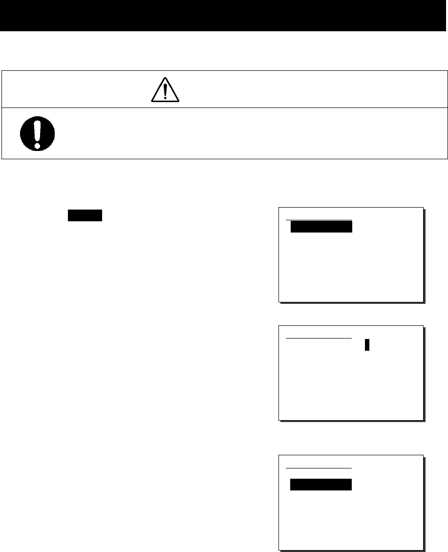
Settings & Registrations
5-1
5. SETTINGS & REGISTRATIONS
This chapter describes the procedure for settings and registrations for the date and time manually,
the contact lists for DSC calls, advanced DSC settings, and other settings for the equipment.
5.1 Date and time setting
Normally, the date and time will be updated automatically if importing GPS information. But if necessary, input
these parameters manually as follows.
CAUTION
The time described below means the present time, and is different from the time in the
menu 9.2 POS/TIME that means the time when the position information is valid.
■ Procedure ■
1
1
1.
.
.
Press the MENU key, and through hierarchical
menus, select the 9.1 Date & time.
2
2
2.
.
.
To input the date, press ENT.
Input the year, month, and date with the numeric keypad
or jog dial. (When using the jog dial, select the value
and press ENT for each digit.)
3
3
3.
.
.
After completed the above steps, the cursor will
move to 2. Present time.
9.1)Date & time
1.Date :'06-12-31
2.Present time : 23:59
3.Display form
- Type : Time,pos
- UTC/LT : UTC
- LT diff : :
- Date format :'YY-MM-DD
0.Back
9.1)Date & time
1.Date :'06-12-31
2.Present time : 23:59
3.Display form
- Type : Time,pos
- UTC/LT : UTC
- LT diff : :
- Date format :'YY-MM-DD
0.Back
9.1)Date & time
1.Date :'06-12-31
2.Present time : 23:59
3.Display form
- Type : Time,pos
- UTC/LT : UTC
- LT diff : :
- Date format :'YY-MM-DD
0.Back

Settings & Registrations
5-2
4
4
4.
.
.
To input the present time (UTC), press ENT.
¾ Input the hours and minutes with the numeric keypad
or jog dial. (When using the jog dial, select the value
and press ENT for each digit.)
¾ To finish this menu, place the cursor on the any one
of the selective items and press the CANCEL key.
In addition to the above, the following items can be set in this menu.
- Type: Select a type shown on the status display from below.
・ "Time,pos" : Displays both of the present time and position.
・ "Time" : Displays only the present time.
・ "Pos" : Displays only the present position.
- UTC/LT: Select a type of time shown on the screen.
- LT diff: Set the local time difference to display the local time.
- Date format: Select a type of date shown on the DSC message lists or the alarm history
from below.
・ " 'YY-MM-DD" : Displays December 31, 2006 as '06-12-31.
・ " MMM DD,'YY": Displays December 31, 2006 as Dec 31,'06.
・ " DD MMM,'YY": Displays December 31, 2006 as 31 Dec,'06.
Note
9.1)Date & time
1.Date :'06-12-31
2.Present time : 23:59
3.Display form
- Type : Time,pos
- UTC/LT : UTC
- LT diff : :
- Date format :'YY-MM-DD
0.Back
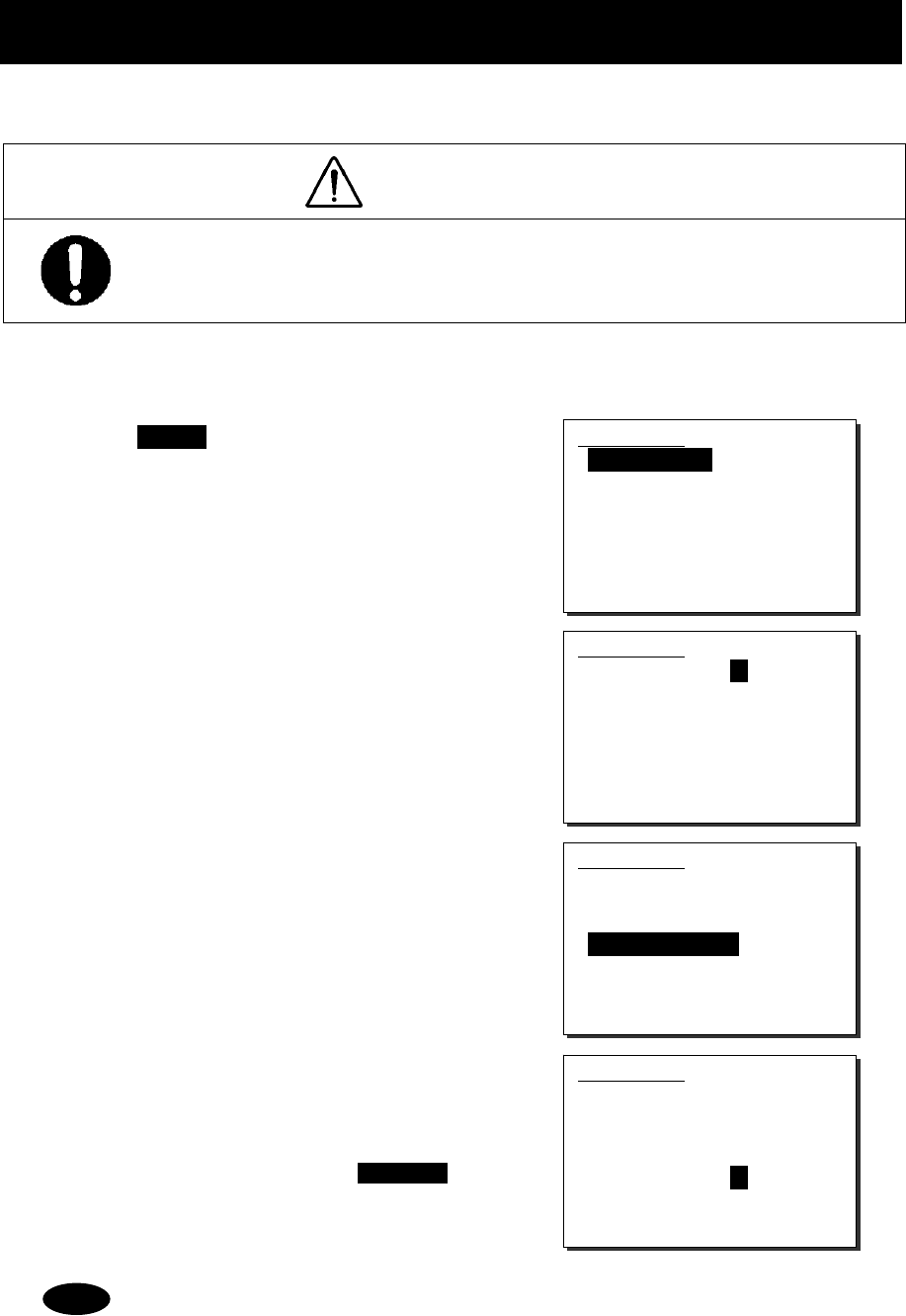
Settings & Registrations
5-3
5.2 Own ship position and time setting
Normally, the ship's position and the time will be updated automatically if importing GPS information.
But if necessary, input these parameters manually as follows.
CAUTION
The time described below means the time when the position information is valid, and is different
from the present time mentioned above.
■ Procedure ■
1
1
1.
.
.
Press the MENU key, and through hierarchical
menus, select the 9.2 POS/TIME.
2
2
2.
.
.
To input own ship's position, press ENT.
Select the position quadrant with the jog dial, and press ENT.
Then input the latitude and longitude, and press ENT with
the numeric keypad or jog dial.
3
3
3.
.
.
After completed the above steps, the cursor will
move to the 2. UTC of position.
4
4
4.
.
.
To input the UTC of position, press ENT.
¾ Input the hours and minutes, and press ENT.
¾ To finish this menu, place the cursor on the any one
of the selective items and press the CANCEL
key.
- If received the position and the time information from the external device, such as a GPS,
the manually entered data will be overwriten automatically.
- If not received the position and the time information within 5 minutes after powering on, or
after 5 minutes elapsed since interrupted, this menu will appear with the alarm automatically.
Further, regardless of either manually or automatically if not updated the position and the
time within 4 hours after the last entry, this menu will appear repeatedly.
9.2)POS/TIME
1.Own position: NE
89゚59'N
179゚59'E
2.UTC of position:
23:59
9.2)POS/TIME
1.Own position: NE
89゚59'N
179゚59'E
2.UTC of position:
23:59
9.2)POS/TIME
1.Own position: NE
89゚59'N
179゚59'E
2.UTC of position:
23:59
9.2)POS/TIME
1.Own position: NE
89゚59'N
179゚59'E
2.UTC of position:
23:59
Note
Settings & Registrations
5-4
5.3 Settings for each Controller
The following describes the procedure regarding individual settings for controller such as LCD adjustment.
5.3.1 LCD adjustment
The LCD conditions for viewability are adjustable as follows.
■ Procedure ■
1
1
1.
.
.
Press the MENU key, and through hierarchical
menus, select the 9.3.1 LCD adjustment.
The screen as shown at right will be displayed.
2
2
2.
.
.
Move the cursor to the desired item and press ENT.
Then alter the settings as appropriate with the
numeric keypad or jog dial and press ENT again.
¾ Set each item within the ranges given below.
・ Contrast: 1 - 13
・ Dimmer: 1 - 10
・ Screen saver: ON/OFF
・ Timer: 1 - 999 seconds
¾ To finish this menu, place the cursor on any one of
the selective items and press the CANCEL key.
5.3.2 Sound settings
The sound settings such as the click beep are adjustable as follows.
■ Procedure ■
1
1
1.
.
.
Press the MENU key, and through hierarchical
menus, select the 9.3.2 Sound.
The screen as shown at right will be displayed.
2
2
2.
.
.
Move the cursor to the desired item and press ENT.
Then set the conditions as appropriate with the
numeric keypad or jog dial and press ENT again.
¾ The phone level can be set within 1 - 8.
¾ The notification level for such as a tone of the popup
screen can be set within 1 - 7.
¾ To finish this menu, place the cursor on any one of
the selective items and press the CANCEL key.
9.3.1)LCD adjustment
1.Contrast : 06
2.Dimmer
Maximum : 10
Typical : 08
Minimum : 06
3.Screen saver : OFF
Timer(sec): 060
0.Back
9.3.1)LCD adjustment
1.Contrast : 06
2.Dimmer
Maximum : 10
Typical : 08
Minimum : 06
3.Screen saver : OFF
Timer(sec): 060
0.Back
9.3.2)Sound
1.Operation
- Internal speaker: ON
- Click : ON
2.Phone level adj. : 7
3.Notification level: 7
0.Back
9.3.2)Sound
1.Operation
- Internal speaker: ON
- Click : ON
2.Phone level adj. : 7
3.Notification level: 7
0.Back
Settings & Registrations
5-5
5.3.3 User key assignment
User key assignment enables the desired menu to be displayed immediately without moving through the
hierarchy menus, and is assignable as follows.
■ Procedure ■
1
1
1.
.
.
Press the MENU key, and through hierarchical
menus, select the 9.3.3 User key assign.
The screen at right will be displayed. If already been
registered, the cursor will be placed on that menu.
2
2
2.
.
.
Move the cursor to the desired menu to be
registered with the jog dial.
The assignable menus are as follows.
1.
2.
3.
4.
5.
6.
7.
8.
9.
10.
11.
12.
13.
14.
15.
16.
17.
18.
DSC coast station call
DSC ship station call
DSC PSTN call
DSC group call
DSC emergency call
DSC test call
DSC logs
AIS other ships list
AIS proximity range
Playback
Public address
Intercom
Scan
Dual watch
Memory channel list
Private channel
Weather channel
Region
(Menu1.1)
(Menu1.2)
(Menu1.3)
(Menu1.4)
(Menu2)
(Menu3)
(Menu4)
(Menu5.1)
(Menu5.3)
(Menu6.1)
(Menu6.2)
(Menu6.3)
(Menu7.1)
(Menu7.2)
(Menu7.3.1)
(Menu7.4)
(Menu7.5)
(Menu7.6)
19.
20.
21.
22.
23.
24.
25.
26.
27.
28.
29.
30.
31.
32.
CH SQL setting
Self diagnosis
DSC loop
Alarm information
System information
DSC AF inspection
Date & time
POS/TIME
My controller
Contact list
DSC operation
Printer property
Dedicated ENT key
CH dial lock ON/OFF
(Menu7.7)
(Menu8.1)
(Menu8.1.5)
(Menu8.2)
(Menu8.3)
(Menu8.5)
(Menu9.1)
(Menu9.2)
(Menu9.3)
(Menu9.4)
(Menu9.5)
(Menu9.7)
---
---
3
3
3.
.
.
Press ENT to complete registration.
¾ After registration, the screen will return to the
previous hierarchical menu as shown at right.
¾ To finish this menu, place the cursor on the any one
of the selective items and press the CANCEL
key.
When the USER key is pressed in the factory default setting, this menu is immediately
displayed.
9.3.3)User key assign
1.DSC coast station call
2.DSC ship station call
3.DSC PSTN call
4.DSC group call
5.DSC emergency call
6.DSC test call
7.DSC logs
9.3.3)User key assign
1.DSC coast station call
2.DSC ship station call
3.DSC PSTN call
4.DSC group call
5.DSC emergency call
6.DSC test call
7.DSC logs
9.3)My controller
1.LCD adjustment
2.Sound
3.User key assign
4.Name :[Station1 ]
5.Hook switch: Valid
6.Off-hook notice: OFF
0.Back
Note
Settings & Registrations
5-6
5.3.4 Name a controller
When connecting multiple controllers, each controller can be named respectively to make identification easier.
The name of each controller is always displayed on the top left of the screen.
■ Procedure ■
1
1
1.
.
.
Press the MENU key and through hierarchical
menus, select the 9.3 My controller.
The screen as shown at right will be displayed.
2
2
2.
.
.
Move the cursor to the 4. Name with the numeric
keypad or jog dial.
3
3
3.
.
.
Press ENT to name the controller.
¾ Up to 10 alphanumeric characters available.
¾ Assigned "StationX (X: address No.)" by default.
¾ The following characters are available.
・ Alphabet (capital and small letters)
・ Numbers 0 - 9
・ The following signs, space and determination(
◄
).
[ ] _ " # % & ' ( ) ? @ + - / = : ; < >
4
4
4.
.
.
Select a character and press ENT one by one.
¾ To change the character at the cursor position, rotate the
jog dial to select the character, and press ENT to move
the cursor to the right. Further, when using the numeric
keypad to input numbers, pressing ENT is not needed.
¾ Only to move the cursor to the right, press ENT.
¾ To return to the previous letter, press the CANCEL
key.
¾ To complete the name entry of 10 characters long, press
ENT after selecting the last character by the jog dial.
Or if less than 10 characters long, following the name,
select the determination as shown at right, and press ENT.
The characters sequence shown by turning the jog dial is as follows.
◄
A B C D E F G H I J K L M N O P Q R S T U V W X Y Z a b c d e f g h i j k l m n o p q r s t
u v w x y z [ ] _ " # % & ' ( ) ? @ + - / = : ; < > 0 1 2 3 4 5 6 7 8 9 (space)
9.3)My controller
1.LCD adjustment
2.Sound
3.User key assign
4.Name :[Station1 ]
5.Hook switch: Valid
6.Off-hook notice: OFF
0.Back
9.3)My controller
1.LCD adjustment
2.Sound
3.User key assign
4.Name :[Station1 ]
5.Hook switch: Valid
6.Off-hook notice: OFF
0.Back
9.3)My controller
1.LCD adjustment
2.Sound
3.User key assign
4.Name :[Station1 ]
5.Hook switch: Valid
6.Off-hook notice: OFF
0.Back
9.3)My controller
1.LCD adjustment
2.Sound
3.User key assign
4.Name :[Bridge1
◄
]
5.Hook switch: Valid
6.Off-hook notice: OFF
0.Back
Note
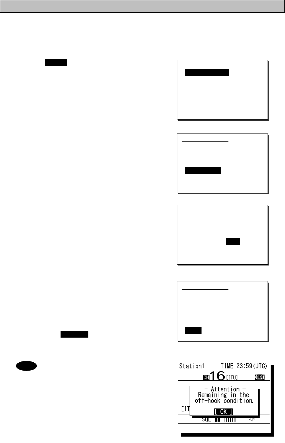
Settings & Registrations
5-7
5.3.5 Disabling the hook switch
The hook switch for the handset can be disabled not to set to CH16 by returning the handset to the cradle.
(As a factory default setting, the hook switch has been set to “Valid”.)
■ Procedure ■
1
1
1.
.
.
Press the MENU key, and through hierarchical
menus, select the 9.3 My controller.
2
2
2.
.
.
Move the cursor to the 5. Hook switch with the
numeric keypad or jog dial.
3
3
3.
.
.
Press ENT.
The cursor will move to the right.
4
4
4.
.
.
Select the condition and press ENT with the jog dial.
¾ When selecting “Invalid”, deletes the line of “6. Off-hook
notice” and the cursor will move to 0. Back.
¾ To finish this menu, place the cursor on the 0.Back
and press ENT, or on any one of the selective items
and press the CANCEL key.
When selecting “Valid” and then set the
condition of the “6. Off-hook notice” to ON,
the popup screen as shown at right will be
displayed if left the handset without returning
to the cradle.
9.3)My controller
1.LCD adjustment
2.Sound
3.User key assign
4.Name :[Bridge1 ]
5.Hook switch: Valid
6.Off-hook notice: OFF
0.Back
9.3)My controller
1.LCD adjustment
2.Sound
3.User key assign
4.Name :[Bridge1 ]
5.Hook switch: Valid
6.Off-hook notice: OFF
0.Back
9.3)My controller
1.LCD adjustment
2.Sound
3.User key assign
4.Name :[Bridge1 ]
5.Hook switch: Valid
6.Off-hook notice: OFF
0.Back
9.3)My controller
1.LCD adjustment
2.Sound
3.User key assign
4.Name :[Bridge1 ]
5.Hook switch: Invalid
0.Back
Note
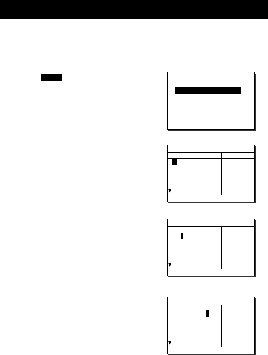
Settings & Registrations
5-8
5.4 Creating contact lists
The following describes the procedure to create the contact lists for a coast station or ship station call, or for a
group call via DSC. Additionally, the PSTN number list can be created using the similar procedure.
(1) Making a new list
■ Procedure ■
1
1
1.
.
.
Press the MENU key, and through hierarchical
menus, select the 9.4 Contact list.
2
2
2.
.
.
Select the desired list to be created with the
numeric keypad or jog dial.
The example at right shows the coast station list.
The following is the procedure in the case of the coast
station list, but is essentially the same with the case of the
ship station list, the group list, or the PSTN number list.
3
3
3.
.
.
Select a line number and press ENT.
The screen becomes the name entry mode.
If the name is left blank and "◄"is pressed, "Unknown" is
displayed and the cursor is moved to MMSI column.
4
4
4.
.
.
Input characters of a name by selecting a
character with the jog dial and ENT one by one.
¾ Up to 14 alphanumeric characters available.
¾ Other procedure are essentially the same with the
name entry procedure in the 9.3 My controller.
9.4)Contact list
1.Coast station list
2.Ship station list
3.Calling group list
4.PSTN number list
0.Back
9.4.1)Coast station list
No NAME MMSI/AIS
01
02
03
04
05
06
Select a line to re
g
ister
/
revise.
9.4.1)Coast station list
No NAME MMSI/AIS
01
02
03
04
05
06
◄
Enter the name b
y
the Jo
g
Dial.
9.4.1)Coast station list
No NAME MMSI/AIS
01
02
03
04
05
06
JRC coast1
◄
Enter the name b
y
the Jo
g
Dial.
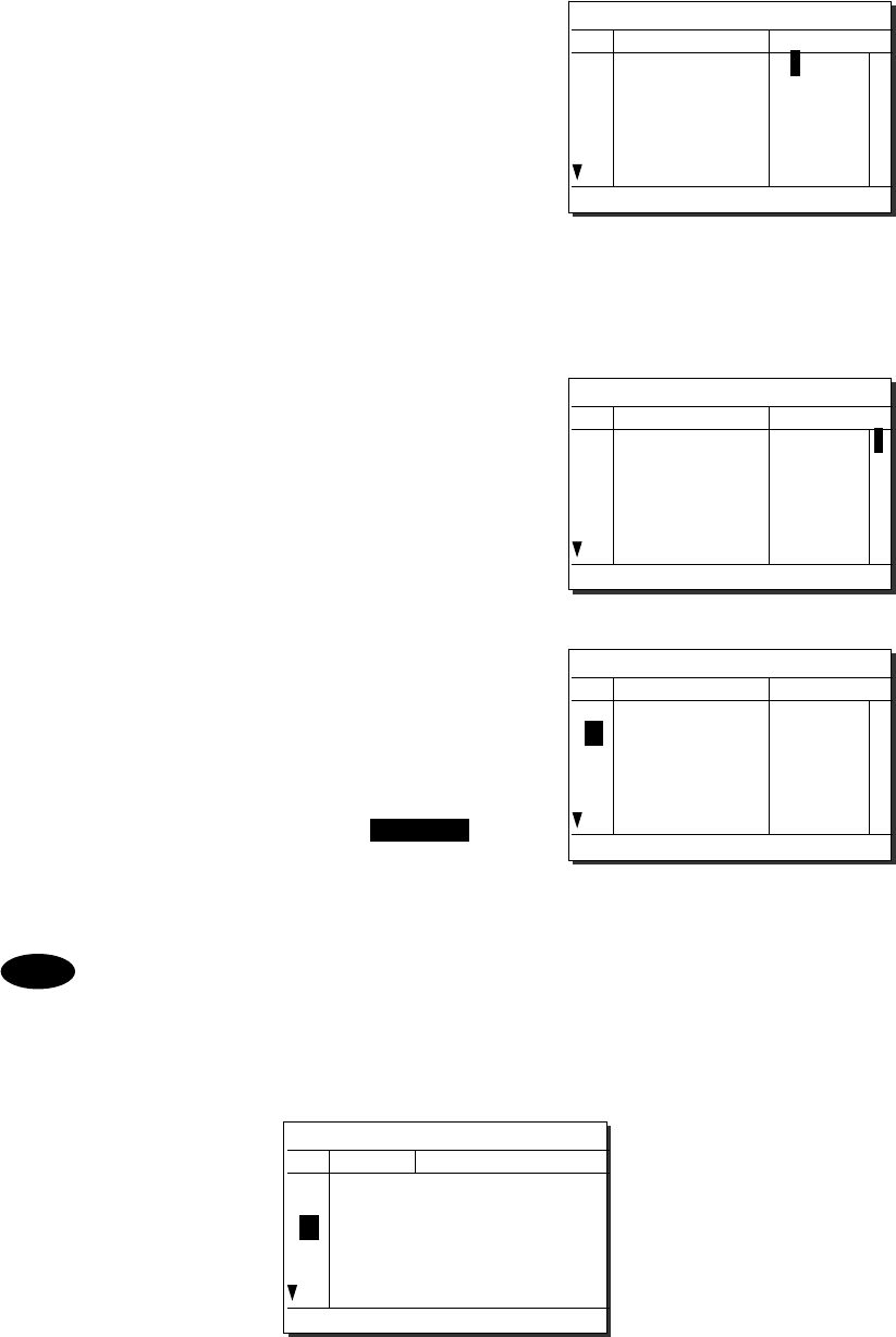
Settings & Registrations
5-9
5
5
5.
.
.
After completed the name entry, the cursor will
move to the MMSI column.
¾ Input the MMSI with the numeric keypad or jog dial.
¾ For coast stations, "00" will be inserted automatically
at the start of the line, and then the line will be ready
for entering numbers. (In the case of the group list,
"0" will be added as well.)
¾ When using the numeric keypad, input all digits
consecutively.
¾ When using the jog dial, select a number and press
ENT for each digit repeatedly.
6
6
6.
.
.
After completed the MMSI entry, the cursor will
move to the AIS column.
To activate the AIS proximity check function for the station,
check "v" sign with the jog dial.
7
7
7.
.
.
After completed the entry of the station, press
ENT to move the cursor to the next line number.
¾ Follow the same procedure above to create the radio
station list.
¾ To finish this menu, place the cursor on any one of
the registration numbers and press the CANCEL
key.
- The maximum registerable number is 80 for each of the coast station list, the ship station list,
and the PSTN number list, and is 20 for the calling group list.
- The registerable telephone number digits are 1 to 16 and the registration screen will be as
shown below.
9.4.1)Coast station list
No NAME MMSI/AIS
01
02
03
04
05
06
JRC coast1 00
Enter the 9-di
g
it MMSI.
9.4.1)Coast station list
No NAME MMSI/AIS
01
02
03
04
05
06
JRC coast1 001234567 v
Select v for AIS
p
roximit
y
check.
9.4.1)Coast station list
No NAME MMSI/AIS
01
02
03
04
05
06
JRC coast1 001234567 v
Select a line to re
g
ister
/
revise.
Note
9.4.4)PSTN number list
No NAME TEL number
01
02
03
JRC office1 <
>1234567890123456
JRC office2 <
>0018143215678
<
>
Select a line to re
g
ister
/
revise.
Settings & Registrations
5-10
(2) Revising a list
■ Procedure ■
1
1
1.
.
.
Select the registration number to be revised at
step3 above, and press ENT.
The example at right shows the case of the No.1
selected to revise the content.
2
2
2.
.
.
To change the name, change the characters with
the jog dial and ENT one by one.
¾ The procedure is basically similar with the step4
mentioned above.
¾ Only to move the cursor to the right, press ENT.
Additionally, when moving the cursor without changing
the name, enter the determination character at the end
of the name.
3
3
3.
.
.
After completed the name revising, the cursor
will move to the MMSI column.
¾ Change the digits of the MMSI with the numeric
keypad or jog dial.
¾ Only to move the cursor to the right, press ENT.
4
4
4.
.
.
After completed the MMSI revising, the cursor will
move to the AIS column.
¾ If required, change the status with the jog dial and
press ENT.
¾ If not required to change the status, press ENT.
5
5
5.
.
.
After completed, the cursor will move to the next
line number.
To finish this menu, press the CANCEL key.
- When the cursor is placed on the line number, pressing two digits of the number enables to
move the cursor to the specified number.
- To erase a registered line, select a space at the beginning of the name and press ENT.
- To erase all data of the currently displaying list, select "00. ALL CLEAR function" button and
press ENT.
Note
9.4.1)Coast station list
No NAME MMSI/AIS
01
02
03
04
05
06
JRC coast1
JRC coast2
JRC coast3
JRC coast4
JRC coast5
JRC coast6
001234567
002345678
003456789
004567890
005678901
006789012
v
Enter the name b
y
the Jo
g
Dial.
9.4.1)Coast station list
No NAME MMSI/AIS
01
02
03
04
05
06
ABC coast
◄
JRC coast2
JRC coast3
JRC coast4
JRC coast5
JRC coast6
001234567
002345678
003456789
004567890
005678901
006789012
v
Enter the name b
y
the Jo
g
Dial.
9.4.1)Coast station list
No NAME MMSI/AIS
01
02
03
04
05
06
ABC coast
JRC coast2
JRC coast3
JRC coast4
JRC coast5
JRC coast6
001234567
002345678
003456789
004567890
005678901
006789012
v
Enter the 9-di
g
it MMSI.
9.4.1)Coast station list
No NAME MMSI/AIS
01
02
03
04
05
06
ABC coast
JRC coast2
JRC coast3
JRC coast4
JRC coast5
JRC coast6
001111111
002345678
003456789
004567890
005678901
006789012
Select v for AIS
p
roximit
y
check.
9.4.1)Coast station list
No NAME MMSI/AIS
01
02
03
04
05
06
ABC coast
JRC coast2
JRC coast3
JRC coast4
JRC coast5
JRC coast6
001111111
002345678
003456789
004567890
005678901
006789012
Select a line to re
g
ister
/
revise.
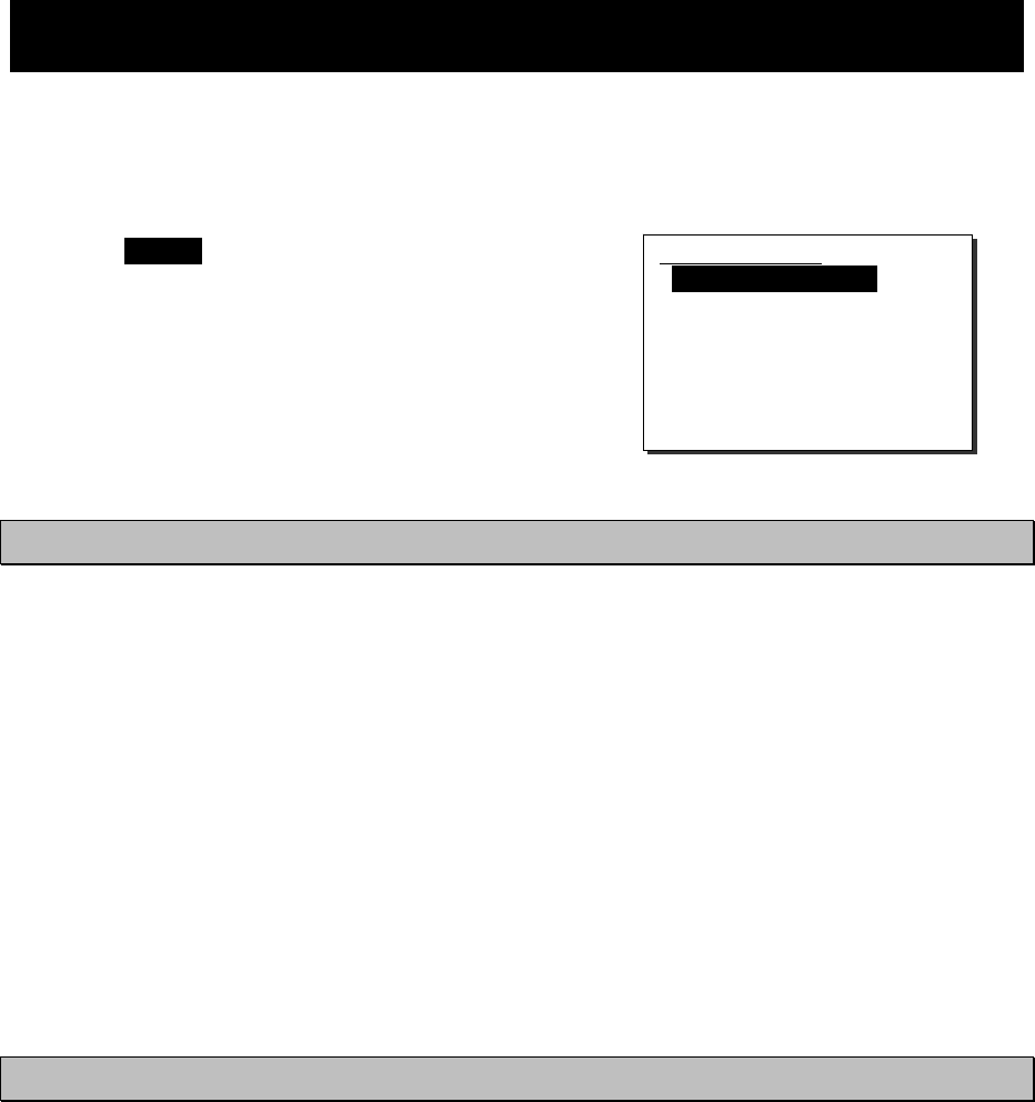
Settings & Registrations
5-11
5.5 Advanced settings for DSC
The following describes the procedure for the advanced DSC settings such as automatic acknowledgement, as
well as creating a PSTN number list.
■ Menu screen ■
Press the MENU key, and through hierarchical
menus, select the 9.5 DSC operation.
The following describes the procedures from this screen.
Note that the screen at right shows factory default settings.
5.5.1 Automatic acknowledgement
If the automatic acknowledgement is set to ON, and when received any one of the individual calls below, the
acknowledgement will be sent automatically without notice.
・ Routine - a polling call
・ Safety - a position request call
・ Safety - a test call
This function will be disabled in distress mode or PSTN communication mode, or while the PTT is ON.
Furthermore, if performed this function during dual watch or scanning, the channel dwell time might be longer
than usual.
■ Procedure ■
To activate the automatic acknowledgement function, set the 1. Automatic ACK condition to ON
with the jog dial.
5.5.2 Disabling the automatic channel shift
When receiving any one of the following DSC calls having a valid working channel, the radiotelephone channel
can be shifted automatically to the specified channel. (Note : For the other DSC calls, the channel shift can be
performed manually.)
・ Routine - a group call
・ Safety - an All ship call
・ Routine/ Safety/ Urgency - an acknowledgement to the individual call own ship has transmitted before.
However, to avoid disruption of the important ongoing communication, this function must be disabled according to
the menu operation. The following describes the procedure to disable this function.
■ Procedure ■
To disable the automatic channel shift function, set the 2. Automatic CH shift condition to OFF
with the jog dial.
9.5)DSC operation
1.Automatic ACK :ON
2.Automatic CH shift :ON
3.Safety/Routine ALM :ON
4.Medical/Neutral use :OFF
5.Expanded MMSI : 0
0.Back
Settings & Registrations
5-12
5.5.3 Disabling receiving alarms for routine and safety calls
The aural alarm for routine and safety calls can be disabled as follows.
■ Procedure■
To disable the receiving alarms for routine and safety calls, set the 3. Safety/Routine ALM
condition to OFF with the jog dial.
5.5.4 Medical/Neutral use setting for urgency calls
The following describes the procedure to set the condition so that an urgency all ships call containing the
additional subject of either "Medical transportation" or "Neutral nationality" can be sent.
Additionally, note that this setting will return to the default setting (OFF) if the power is turned off.
■ Procedure ■
To use these kinds of calls, set the 4. Medical/Neutral use condition to ON with the jog dial.
5.5.5 Expanded MMSI registration
If existing multiple DSC devices having the same 9-digit MMSI on board a ship, setting the 10th digit of the MMSI
number to a non-zero value is available to distinguish them in the case of routine individual calls.
The handling of 10-digit MMSI is as follows.
・ When sending a routine individual call, the caller ID (own ship station's MMSI) will be 10-digit MMSI.
・ When receiving a routine individual call, the DSC having the identical address only will treat the message, i.e.
mainly the DSC having "0" as the 10th digit of MMSI will receive an individual call addressed to the own
station.
・ When sending an acknowledgement to a received individual call, the address of the call will be entered the
caller's ID of the individual call as it is, i.e. if the 10th digit of the caller's ID is not "0", the address will be
10-digit MMSI automatically.
■ Procedure ■
To register the 10th digit of own MMSI, set the number to the 5. Expanded MMSI condition with
the numeric keypad or the jog dial.
CAUTION
Usually, it is not necessary to set it as any values other than zero.”0”.
Please be sure to set the VHF transceiver installed in a bridge as “0”
When values other than “0” are set up, DSC may be unable to receive.
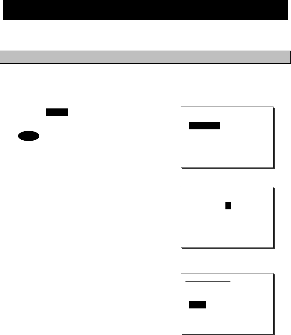
Settings & Registrations
5-13
5.6 Other settings
The following describes the procedure to set the conditions regarding the AIS information import, the printer
property, and preset squelch with respect to each channel.
5.6.1 Enabling the AIS function
When connecting the AIS to use the information for such as a DSC call, set the import condition to ON as follows.
■ Procedure ■
1
1
1.
.
.
Press the MENU key, and through hierarchical
menus, select the 9.6 AIS function.
The factory setting is default “ON”.
2
2
2.
.
.
Press ENT. Then set the import condition to ON
with the jog dial.
3
3
3.
.
.
Press ENT to complete the setting.
The cursor will move to the 0. Back.
9.6)AIS function
1.Import : OFF
0.Back
Note
9.6)AIS function
1.Import : ON
0.Back
9.6)AIS function
1.Import : ON
0.Back
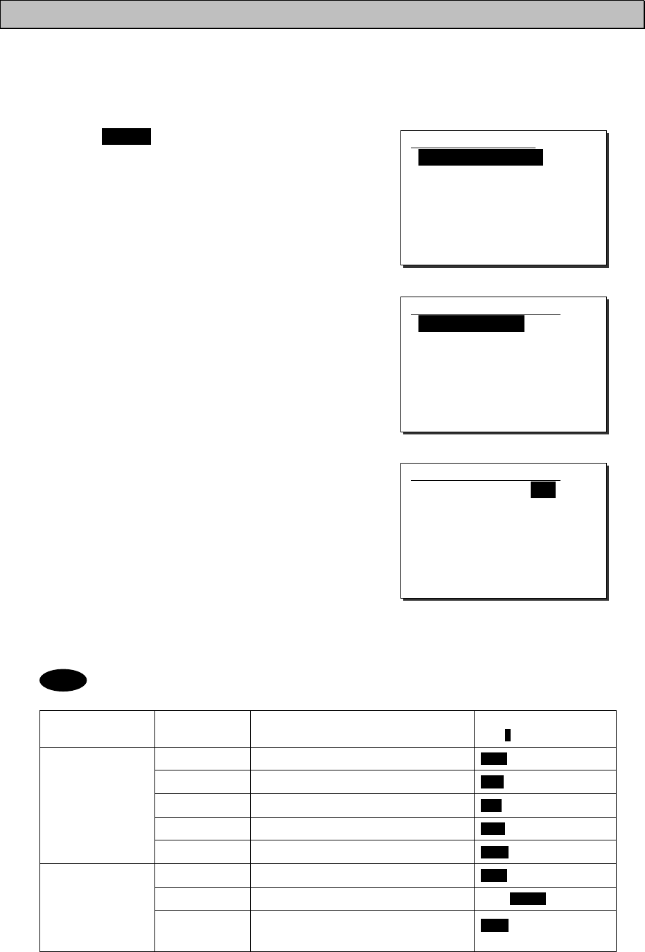
Settings & Registrations
5-14
5.6.2 Printer property
When connecting the printers, configure the conditions as appropriate according to the printer type, as follows.
■ Procedure ■
1
1
1.
.
.
Press the MENU key, and through hierarchical
menus, select the 9.7 Printer property.
2
2
2.
.
.
Select the intended printer and press ENT.
When selected the 1. Controller printer, the screen at right
will be displayed.
3
3
3.
.
.
Move the cursor to the desired item and press ENT.
The cursor will move to the right. After that, select the
condition as appropriate and press ENT.
- The content and the selective conditions of each item are as follows.
Printer type Selective item Content Selective conditions
( : Factory default)
Connection Connection status and the printer type None/ Serial
Data out Printing method for the DSC message Auto/ Manual
Baudrate Transmission speed to the printer 4.8k/ 9.6k/ 38.4kbps
Flow control Handshake setting with the printer Hard/ None
Controller printer
Print direction Printing sequence of the lines Invert/ Upright
Connection Connection status and the printer type None/NKG-52/Centronics
Data out Printing method for the DSC message Auto/ Manual
Transceiver printer
Print direction Printing sequence of the lines Invert/ Upright
(NKG-52: “Invert” only)
Note
9.7)Printer property
1.Controller printer
2.Transceiver printer
0.Back
9.7.1)Controller printer
1.Connection :None
2.Data out :Auto
3.Baudrate :4.8k
4.Flow control :Hard
5.Print direction:Invert
0.Back
9.7.1)Controller printer
1.Connection :None
2.Data out :Auto
3.Baudrate :4.8k
4.Flow control :Hard
5.Print direction:Invert
0.Back
Settings & Registrations
5-15
- When connect NKG-91 printer, please set up as follows.
1.Connection: Serial
2.Data out: Auto
3.Baudrate: 4.8k
4.Flow control: Hard
5.Print direction: Invert
- When connect DPU-414 printer, please set up as follows.
1.Connection: Serial
2.Data out: Auto
3.Baudrate: 4.8k
4.Flow control: Hard
5.Print direction: Upright
- When connect NKG-52 printer, please set up as follows.
1.Connection: NKG-52
2.Data out: Auto
3.Print direction: Invert
Settings & Registrations
5-16
Maintenance & Inspection
6-1
6. MAINTENANCE & INSPECTION
The performance and lifetime of the equipment depend on the appropriate maintenance.
This chapter describes the maintenance and inspection, self diagnosis, and outline of adjustment.
6.1 General maintenance & inspection
In order to operate the equipment under optimum conditions, it is vital to perform regular inspections and also, to
keep accurate records. Inspections enable problems to be identified before they become major malfunctions.
The following inspections should be made regularly.
Inspection
sequence Inspection items Procedure
1 Antenna system Check that antennas and the connectors are secure.
2 Squelch operation
Lift the handset of the controller with the access rights, and turn
the SQL control fully counterclockwise. Check for noise from the
speaker. Check noise to be suppressed by turning the SQL
control clockwise.
3 Receiver condition checked
by speaker output.
Check that the voice level and noise level are not abnormally
loud or soft.
4 Handset PTT switch Press PTT and check that the unit transmits immediately and
that TX is displayed on the screen.
5
Transmission and reception
checked by performing radio
communication.
Check that normal conversation is possible.
Maintenance & Inspection
6-2
6.2 Self diagnosis inspection
The following describes the procedure to perform the self diagnosis with the menu 8.1 Self diagnosis.
■ Procedure ■
1
1
1.
.
.
Press FUNC Î 8
TEST .
The menu shown at right will be displayed.
2
2
2.
.
.
Select 1. Transceiver or 2. Controller with the
numeric keypad or the jog dial.
If selected "1. Transceiver", the screen at right will be
displayed.
3
3
3.
.
.
Select a test type with the jog dial and press ENT.
¾ The self diagnosis will be performed.
¾ The following test modes are available.
8.1.1) Transceiver ....... ALL (All modes)
DGT CKT (ROM/RAM/SIO)
MODEM (MODEM only)
Loop (Loop only)
PS (PS(DC/DC) only)
Printer (Printer only)
8.1.2) Controller ........ ALL (All modes)
DGT CKT (ROM/RAM/SIO)
LCD&LED (LCD&LED only)
Printer (Printer only)
Speaker (Speaker only)
- Only the case where printer setup is ON can choose Printer in test mode.
- To break off the self diagnosis, press the CANCEL key.
- The results of the self diagnosis are stored and the latest up to 10 logs can be confirmed
from the menu 8.1.3 Transceiver log or 8.1.4 Controller log.
- The self-diagnosis test contents and results are as shown below.
8.1)Self diagnosis
1.Transceiver
2.Controller
3.Transceiver log
4.Controller log
5.DSC loop
0.Back
8.1.1)Transceiver
Start checking of ALL
- ROM : OK
- RAM : OK
- SIO : OK
- MODEM : OK
- Loop : OK
- PS(DC/DC) : OK
- Printer : DONE
Note
8.1.1)Transceiver
Start checking of ALL
- ROM : --
- RAM : --
- SIO : --
- MODEM : --
- Loop : --
- PS(DC/DC) : --
- Printer : --

Maintenance & Inspection
6-3
Unit Name Test Item Contents Results
ROM ・ ROM1 (Flash) read/write
・ ROM2 (EEP) read/write
OK :Normal
ROM1 NG :ROM1 error
ROM2 NG :ROM2 error
ROM12 NG :ROM1 & 2 error
RAM ・ RAM (SDRAM) read/write OK :Normal
NG :Error
SIO ・ RS-485 line loop-back test OK :Normal
NG :Error
MODEM ・ MODEM1 (M0-M1) loop-back test
・ MODEM2 (M1-M0) loop-back test
OK :Normal
MODEM1 NG :MODEM1 error
MODEM2 NG :MODEM2 error
MODEM12 NG :MODEM1 & 2 error
Loop ・ Loop1 (TX-RX) loop-back test
・ Loop2 (TX-WKR) loop-back test
OK :Normal
Loop1 NG :Loop1 error
Loop2 NG :Loop2 error
Loop12 NG :Loop1 & 2 error
PS(DC/DC)
・ DC/DC PWR output voltage check OK :Normal
NG :Error
Transceiver
Printer ・ Print out test
- Check visually if printed out
correctly.
- After performed, this line on the
screen shows "DONE".
ROM ・ ROM1(Flash) read/write
・ ROM2(EEP) read/write
OK :Normal
ROM1 NG :ROM1 Error
ROM2 NG :ROM2 Error
ROM12 NG :Error in both
RAM ・ RAM(SDRAM) read/write OK :Normal
NG :Error
SIO ・ RS-485 line loop-back test OK :Normal
NG :Error
LCD&LED ・ Every pixel (dot) of the LCD and
ALM lamp display test
- Check visually if every dot and
the red and green ALM lamp
alternately work normally for 3
seconds.
- After performed, this line on the
screen shows "DONE".
Printer ・ Print out test
- Check visually if printed out
correctly.
- After performed, this line on the
screen shows "DONE".
Controller
Speaker ・ Sound test
- Check aurally if the 1500Hz tone
sounds correctly. After that, press
ENT on the popup screen to finish
this process.
- After performed, this line on the
screen shows "DONE".
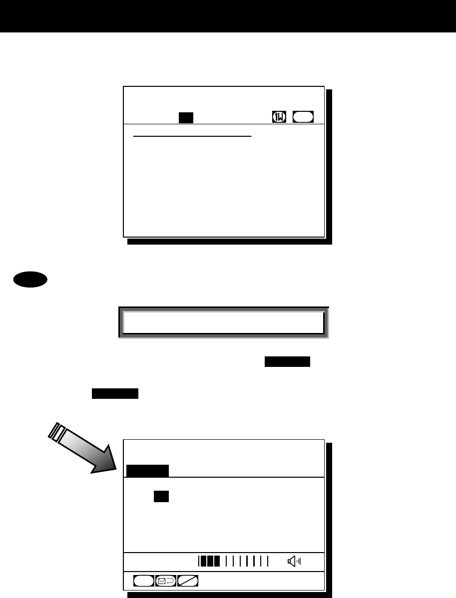
Maintenance & Inspection
6-4
6.3 System alarm indication
If detected errors regarding the equipment, the screen shows the alarm information as follows.
- According to the alarm type, some features and functions may be automatically restricted.
The alarm information is formatted as follows.
[Alarm Date and Time]
[Alarm Number], [Popup Information]
- To return to the previous screen, press the CANCEL key.
- When occurring 002.TX PLL unlock alarm or 003.RX PLL unlock alarm, a blinking
UNLOCK mark will be additionally indicated. In this case, that mark will be remained
as shown below until restored to the normal condition.
Note
Alarm information
'06-12-31 23:59
001,TRCVR high temp
004,WKR PLL unlock
Station1 TIME 23:59(UTC)
16
CH70
CH [ITU]
Station1 TIME 23:59(UTC)
POS 89゚59'S
EXT 179゚59'W
16
CH
SQL
CH70
CHSW
[ITU]
UNLOCK

Maintenance & Inspection
6-5
6.3.1 Alarm list
The following list shows the types of system alarm and contents.
Alarm
Number Display Contents Troubleshooting Procedure
001 TRCVR high temp Detected the abnormally high temperature
in the transceiver.
Stop transmission, or
reduce the power to 1W
002 TX PLL unlock Detected PLL Unlock in the transmitter. Please contact JRC or
our agency.
003 RX PLL unlock Detected PLL Unlock in the receiver. Please contact JRC or
our agency.
004 WKR PLL unlock Detected PLL Unlock in the watch-keeping
receiver.
Please contact JRC or
our agency.
005 TRCVR memory Detected the transceiver memory error. Please contact JRC or
our agency.
006 CTLR1 memory Detected the memory error in controller 1. Please contact JRC or
our agency.
007 CTLR2 memory Detected the memory error in controller 2
or channel selector 2.
Please contact JRC or
our agency.
008 CTLR3 memory Detected the memory error in controller 3
or channel selector 3.
Please contact JRC or
our agency.
009 CTLR4 memory Detected the memory error in controller 4
or channel selector 4.
Please contact JRC or
our agency.
010 CTLR5 memory Detected the memory error in controller 5
or channel selector 5.
Please contact JRC or
our agency.
011 CTLR1 SIO Detected the serial communication error
in controller 1.
Please contact JRC or
our agency.
012 CTLR2 SIO Detected the serial communication error
in controller 2 or channel selector 2.
Please contact JRC or
our agency.
013 CTLR3 SIO Detected the serial communication error
in controller 3 or channel selector 3.
Please contact JRC or
our agency.
014 CTLR4 SIO Detected the serial communication error
in controller 4 or channel selector 4.
Please contact JRC or
our agency.
015 CTLR5 SIO Detected the serial communication error
in controller 5 or channel selector 5.
Please contact JRC or
our agency.
016 GPS SIO Detected the GPS communication error Please contact JRC or
our agency.
017 Serial printer1 Detected an alarm of the printer 1. Check the printer power or
the paper empty.
018 Serial printer2 Detected an alarm of the printer 2. Check the printer power or
the paper empty.
019 Parallel printer Detected an alarm of the Centronics type
printer connected to the transceiver.
Check the printer power or
the paper empty.
020 MMSI lost The MMSI has not been registered yet, or
has been lost.
Please contact JRC or
our agency.
021 Own CTLR ID
Detected the ID error in the controller
displaying this message. It is recorded on
the alarm history as alarm of No. 011-015.
Please contact JRC or
our agency.
022 Own CTLR SIO
Detected the loss of communication with
the transceiver via RS-485 lines. It is
recorded on the alarm history as alarm of
No. 011-015. However, it may not be
recorded on the alarm history.
Please contact JRC or
our agency.
023 PTT line Detected malfunction regarding PTT line. Please contact JRC or
our agency.
024 TRCVR PS (DC/DC) Detected DC/DC power supply error. Please contact JRC or
our agency.
025 TRCVR PS (FUSE) Detected PS error at the RF circuit, e.g.
the fuse blown.
Check or replace the fuse
(F3) on the CBD-7701 T/B.
026 Abnormal RF power Detected malfunction in the transmission
circuit or the duplexer connection.
Please contact JRC or
our agency.
027 POWER-OFF failure Detected malfunction regarding power
supply control circuit.
Turn OFF the power switch
in the transceiver or of the
external power source, and
then please contact JRC or
our agency.
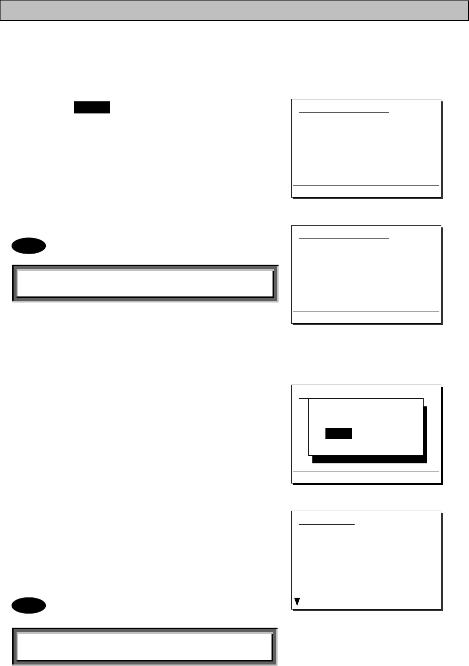
Maintenance & Inspection
6-6
6.3.2 Viewing the alarm history
The following describes the procedure to confirm the current alarm condition or the alarms occurred in past time.
■ Procedure ■
1
1
1.
.
.
Press the MENU key, and through hierarchical
menus, select the 8.2 Alarm information.
According to the alarm occurring condition, the screen
will be displayed as shown at right.
The displayed alarm information is formatted as follows.
[Alarm Number], [Popup Information]
2
2
2.
.
.
To check the alarm history, press ENT.
After the popup screen at right will be displayed, select OK.
3
3
3.
.
.
The alarm history will be displayed.
The latest up to 10 histories are stored.
If necessary, scroll with the jog dial.
The displayed alarm history is formatted as follows.
[Number] [Alarm and Recovery Date and Time] [Alarm Number]
[A: Alarm/V: Recovery] [Popup Information]
8.2)Alarm information
No data
Press ENT to view alarm history.
8.2)Alarm information
'06-12-31 23:59
001,TRCVR high temp
004,WKR PLL unlock
Press ENT to view alarm history.
View alarm history?
[ OK ] [Cancel]
Alarm history
1.'06-12-31 23:59 001 A
TRCVR high temp
2.'06-12-31 23:59 004 A
WKR PLL unlock
3.'06-11-25 06:33 000 V
TRCVR VSWR
Note
Note
8.2)Alarm information
001,TRCVR high temp
004,WKR PLL unlock
Press ENT to view alarm history.
(In the case of alarms occurring)
(In the case of no current alarm)
Maintenance & Inspection
6-7
6.4 Checking the setup condition
The system information can be confirmed for use in maintenance and inspection.
6.4.1 System information
The following describes the procedure to display such as the ID numbers or peripheral connection conditions.
■ Procedure ■
1
1
1.
.
.
Press the MENU key, and through hierarchical
menus, select the 8.3 System information.
The screen as shown at right will be displayed.
If necessary, scroll with the jog dial.
The confirmable information is described below.
Item Name Contents Notes
Self-ID Own ship's identification number (MMSI)
Group-ID The identification number of the group own ship belongs to
ATIS-ID The ATIS number for European inland waterways
Num of CTLRs The number of connected controllers
Own CTLR ID The address number of this controller
WKR The setting status to use the watch-keeping receiver Default setting: Valid
User key asgn The menu assigned to the user defined key
Priority CH The registered priority channel number Default setting: CH16
Hook switch The setting status to use the handset hook detection Default setting: Valid
TX monitor The setting status to monitor communications of a controller at the
other controllers and the external speaker Default setting: ON
Alarm wake-up The setting status to use the automatic startup function in sleep
mode if receiving a distress signal Default setting: ON
AIS info The AIS connection status (Receiving/ Disrupted/ Invalid)
AME info The AME connection status (Normal/ CS error/ Invalid)
Serial number The serial product number of the JHS-770S/780D
6.4.2 Software version
To confirm the software version, press the MENU
key and through hierarchical menus, select the 8.4
Software version.
The software version number of the transceiver and
controller will be displayed as shown at right.
8.3)System information
Self-ID :123456789
Group-ID :012345678
ATIS-ID :9431011234
Num of CTLRs :4
Own CTLR ID :2
WKR :Valid
User key asgn :AIS screen
Note
8.4)Software version
- Transceiver : 1.00
- Controller : 1.00
0.Back
Maintenance & Inspection
6-8
6.5 DSC AF inspection
DSC AF modulation frequencies can be checked for periodic inspections etc.
■ Procedure ■
1
1
1.
.
.
Press the MENU key, and through hierarchical
menus, select the 8.5 DSC AF inspection.
2
2
2.
.
.
Select output port of DSC AF frequencies.
¾
¾
¾
The following ports are available.
VDR&SP VDR terminal and controller speaker
VDR&ExHS VDR terminal and external handset
VDR&ExSP VDR terminal and external speaker
terminal
3
3
3.
.
.
Select DSC modulation frequencies.
¾
¾
¾
The following frequencies are available.
2100Hz Space frequency (B)
1300Hz Mark frequency (Y)
Dot Dot pattern
4
4
4.
.
.
Output
DSC AF sound is outputted by 3.Execution.
Sound can be stopped by the CANCEL key or
3.Execution once again.
8.5)DSC AF inspection
1.Output port :VDR&SP
2.DSC mod type :2100Hz
3.Execution :Start
0.Back
8.5)DSC AF inspection
1.Output port :VDR&SP
2.DSC mod type :2100Hz
3.Execution :Start
0.Back
8.5)DSC AF inspection
1.Output port :VDR&SP
2.DSC mod type :2100Hz
3.Execution :Start
0.Back
8.5)DSC AF inspection
1.Output port :VDR&SP
2.DSC mod type :2100Hz
3.Execution :Start
0.Back
Maintenance & Inspection
6-9
6.6 Troubleshooting
WARNING
This unit is also used for the distress communication, in addition to usual communication.
Contact JRC or our agent if any problem is observed in this unit on usual operation or
inspection. Do NOT ignore or leave any problems of this unit.
Always use the specified fuse when replacing a fuse. Using a different fuse may result
in fire or malfunction.
Do not open the equipment to inspect or repair it. Inspection or repairs by anyone other
than a specialized technician may result in fire, electrical shock, or malfunction.
If internal inspection or repair is necessary, contact our service center or agents.
6.6.1 Procedures for locating malfunctions
1) First, check the power supply voltage, fuses, and connectors.
2) If there are no problems with the above, use a tester to check for errors.
The following table shows the instruments required for effect repairs and the severity of the malfunctions.
If required to locate the malfunction, with the exception of qualified service personnel, perform the following
No. 1 and 2 only.
No. Type of Malfunction Examples
1 Faults requiring no instrument to locate
・ Blown power supply fuse
・ Faulty contacts
・ Broken antenna cables
・ Defective switches, volume, etc.
・ Other problems that can be visually detected
2 Malfunctions that can be fixed with a
tester and repaired
・ Power supply voltage confirmation
・ Breaks in internal wiring
3 Malfunctions requiring special instrument
・ Crystal oscillator frequency error
・ Decrease in transmitting power and reception
sensitivity
・ Decrease in transmitter modulation level
・ Malfunctions in semiconductors, ICs, and similar
equipment

Maintenance & Inspection
6-10
6.6.2 Guide to locating faults
Use the following table as a guide to locating the causes of malfunctions in the equipment. Additionally when
contacting JRC or our agency, please provide the malfunction condition.
No. Symptom Typical causes
1 Displays nothing on the screen.
・ Malfunction in the controller cable
・ Abnormal power supply voltage
・ Power supply fuse is blown
・ Malfunction in the power switch
・ Malfunction in the display circuit
・ Malfunction in the control circuit
2 TX is displayed but no voice is
transmitted.
・ Malfunction in the handset
・ Malfunction in the controller cable
・ Malfunction in the AF signal transmission circuit
3 TX is not displayed, and
transmission is not possible.
・ Malfunction in the handset PTT switch
・ Malfunction in the hook detection circuit
・ Malfunction in the transmission circuit
4 Reception sensitivity is poor.
・ Antenna damage
・ Break or short circuit of antenna cable
・ Faulty contact in antenna connectors
5
No sound from the speaker even
when squelch is opened without
reception.
・ Malfunction in the speaker
・ Malfunction in the SQL control
・ Malfunction in the receiver circuit
6 Noise is output from the speaker, but
own ship cannot receive any calls.
・ Antenna damage
・ Break or short circuit in antenna cable
・ Faulty contact in antenna connectors
・ Malfunction in the receiver
7 Turning SQL does not suppress
noise.
・ Malfunction in the SQL control
・ Malfunction in the receiver
The following are not faults.
Symptom Possible causes Handling
No response from other station via
radiotelephone or DSC call.
No operator in that station, or
unavailable to respond due to other
duties.
Wait and retry later.
Unable to control the radiotelephone
or DSC, but the VOL control, the
dimmer, and PWR key.
That controller is in the monitor
mode.
Press ENT to obtain the access right
and after that, retry the operation.
Even if pressing ENT at the monitor
controller, the access right cannot
be obtained.
Another controller with higher priority
is in use for communicating or
performing menu operations.
After finished at another controller,
retry the operation.
If the system is left on a screen
other than the status display for a
while, returns to the status display.
After 10 minutes leaving, the
inactivity timer would be activated
and returned to the status display.
Regulated specification by ITU-R
M.493-11.
(Do not leave the equipment during
menu operation.)
The received distress call log have
erased without operating.
Received distress calls are
automatically deleted after 48 hours.
Regulated specification by IMO
A.803(19).
When a portable transceiver is
brought close to a controller, noise
comes out from a portable
transceiver.
It is based on the influence of the
radio frequency noise slightly
generated from the lighting circuit of
a controller display.
Controller screen lighting is switched
off or a portable transceiver is kept
away 1m or more.
Note
Maintenance & Inspection
6-11
6.6.3 Repair units/parts
The repair units and replacement part units are as follows.
● NTE-770S/780D VHF TRANSCEIVER
Name Unit/Part Name Notes
CONTROL & AF UNIT CDJ-7701S/ 7701D Suffix S: for 770S, D: for 780D
TRX UNIT CMN-7701S/ 7701D Suffix S: for 770S, D: for 780D
TERMINAL BOARD CBD-7701
DUPLEXER CFF-851 For the NTE-780D only
EXTENSION BOARD CQD-7701 Option
TRX ANT CABLE 7ZCJD0291 1.5D coaxial (350mm)
WKR ANT CABLE 7ZCJD0292 1.5D coaxial (300mm)
FUSE MF61NR 250V 15 15A, for F1 *
FUSE MF61NR 250V 15 15A, for F2 *
FUSE MF61NR 250V 10 10A, for F3 *
* Containing to the spare parts kit (7ZXJD0096)
● NCM-1770 VHF CONTROLLER
Name Unit/Part Name Notes
CONTROL UNIT CDJ-3770
AF CONT UNIT CMV-3770
LCD UNIT CDE-3770
MAIN PANEL UNIT CCK-3771
SUB PANEL UNIT CCK-3772
SPEAKER 7USJD0002
CONTROLLER CABLE 7ZCJD0299A Control cable (5m)
● NBD-865 AC/DC POWER SUPPLY (Option)
Name Unit/Part Name Notes
FUSE MQ4 250V 8A 8A, for AC FUSE
FUSE MQ4 250V 8A 8A, for AC FUSE
FUSE FGB1 250V 15A 15A, for F1
FUSE FGB1 250V 15A 15A, for F2
FUSE CES14 250V 15A 15A, for F3
6.6.4 Regular replacement parts
The following shows the part to be replaced regularly. Please contact JRC or our agency to order it.
Part Name Model Name Replacement Period
LCD unit CDE-3770 Approx 20,000 hours of continued
use at maximum brightness
After-Sales Service
7-1
7. AFTER-SALES SERVICE
★ Warranty
The warranty period is determined by JRC's warranty regulations, but is normally 1 year
from the date of purchase.
★ Repair Part Inventory Period
Parts necessary for proper functioning of this equipment will be kept available for 10 years
after product discontinuation.
★ When Requesting Repairs
If what appears to be a defect is detected, refer to "6.5 Troubleshooting" to check if the
equipment is actually defective.
If the problem is due to a defect, immediately stop use of the system and contact the store at
which you purchased the system, or one of our branches.
● During the warranty period, if a malfunction occurs with the equipment while in standard
usage in accordance with this instruction manual, we or our agencies will repair the
malfunction at no charge at the store at which the equipment was purchased or another
location specified by JRC. If the malfunction occurs due to improper usage, fault, fire
or natural disasters, JRC will perform repairs on the equipment for a fee.
● After the warranty expires, we will repair the malfunction for a fee, if repair is possible.
● Please inform us of the following.
☆ Product name, model name, manufactured date, serial number
☆ As much information as you can provide about the malfunction. (Alarm number,
whether transmission is possible or not, etc.)
☆ Your company or organization name, address, and phone number
★ Periodical Maintenance Recommendation
Depending on usage conditions, with extended use, the performance of this equipment may
degrade over time, and externally installed parts such as the antenna may degrade due to
vibration, so we recommend periodical maintenance in addition to the standard maintenance.
Please contact the store at which you purchased the equipment, or one of our branches, to
request periodical maintenance. Periodical maintenance requires a service charge.
If you have any questions regarding after-sales service, please contact the store at which you
purchased the equipment, or one of our branches.
Refer to the inside of the back cover for contact numbers and locations.
Disposal
8-1
8. DISPOSAL
Observe all rules and regulations of the local authorities when disposing of this equipment.

Specifications
9-1
9. SPECIFICATIONS
9.1 JHS-770S/780D Marine VHF Radiotelephone
● General Specifications
Transmission frequency Simplex/ semi-duplex: 155.000 - 163.500MHz
Duplex (JHS-780D) : 156.025 - 157.425MHz
Reception frequency Simplex/ semi-duplex: 155.000 - 163.500MHz
Duplex (JHS-780D) : 160.625 - 162.025MHz
Number of channels ITU/USA/Canada/IWW channels: Maximum 57 ch
Weather channels: 10ch
Private channels: Maximum 200ch
Memory channels: Maximum 10ch
Channel spacing 25kHz
Communication modes Simplex , semi-duplex and duplex (JHS-780D) / press talk
Type of emission Radiotelephone communications: F3E (G3E)
DSC/ATIS: F2B (G2B)
Antenna impedance 50 unbalanced
Transmission/reception switching
interval
300 ms or less
Channel switching interval 5 sec or less
Interface IEC61162-1 (GPS/AME/RMS)
IEC61162-2 (AIS)
600 balanced (VDR), 600 imbalanced (Ext SP)
Main controls DSC call transmission (sending and receiving), communication
channel settings, transmission power settings, squelch adjustment,
volume adjustment, screen adjustment
Power supply voltage 24VDC (21.6VDC - 31.2VDC)
Current consumption 25W transmission: Maximum 8.0A
Reception: Maximum 5.0A
Operating temperature range -15°C - +55°C (for full performance: 0°C - +40°C )
Storage temperature range -15°C - +55°C
Humidity resistance No abnormality after standing 4 hours in +40ºC, 93% RH
Vibration resistance (3 Axis) 5Hz – 12.5Hz: Full amplitude 3.2mm
12.5Hz – 25Hz: Full amplitude 0.8mm
25Hz – 50Hz: Full amplitude 0.2mm
No abnormality after vibration for 15 minutes in each axis
No abnormality after testing resonance points for 30 minutes
Continuous operation (Phone) No abnormality after operating continuously for 8 hours
Continuous operation (DSC, WKR) No abnormality after operating continuously for 24 hours
Protection rating IP22 equivalent (Controller panel)
Dimensions and mass Transceiver unit
240(W)x290(H)x128(D) [excluding projections]
Approximately
6.3
kg
(NTE-770S) / 6.9
kg
(NTE-780D)
Controller unit
230(W)x142(H)x89(D) [excluding projections],
Approximately 1.3
kg

Specifications
9-2
● Transmitter
Antenna output power 8W - 25W (Reduced output: 0.5W - 1W) +20%, -50%
Oscillation method Frequency synthesizer
Modulation method Frequency modulation
Carrier frequency error ±1.5kHz or less
Maximum frequency deviation ±5kHz or less
Occupied bandwidth 16kHz or less
Pre-emphasis characteristics 6dB/oct within +1dB, -3dB
Overall distortion 10% or less
Adjacent channel power -70 dB or 0.2 W or less
Unwanted emissions in the
out-of-band domain 3.125µW or less
Unwanted emissions in the spurious
domain 3.125µW or less
Spurious emissions
(EN300 338, EN301 925)
9kHz-2GHz: 0.25µW or less
2GHz-4GHz: 1µW or less
Residual modulation -40dB or less
● Receiver
Receiving system Double superheterodyne
1st IF 21.4MHz
2nd IF 455kHz
Local oscillation frequency Reception frequency - 21.4 MHz
Local oscillation method Frequency synthesizer
Frequency accuracy ±10 x 10-6 or less
Sensitivity (phone) 6dB V or less (SINAD=20dB)
Sensitivity (DSC) 1% or lower symbol error rate at 0dB V
Selectivity 6dB bandwidth: 12kHz or more, 70dB selectivity: 25kHz or less
Signal-to-Noise ratio 40dB or more
Audio output variance 3dB or less
De-emphasis characteristics 6dB/oct, within +1dB, -3dB
Co-channel selectivity -10 - 0dB
Adjacent channel selectivity Sensitivity ratio 80dB or more
Desensitization effect (phone) 80dBµV or more
Desensitization effect (DSC) Symbol error rate of 1% or better at a wanted signal level of 3dB V
and an unwanted signal level of 73dB V
Spurious response (phone) Sensitivity ratio 70dB or more
Spurious response (DSC) Symbol error rate of 1% or better at a wanted signal level of 3dB V
and an unwanted signal level of 73dB V
Intermodulation characteristics
(phone) 65dBµV or more
Intermodulation characteristics
(DSC)
Symbol error rate of 1% or better at a wanted signal level of 3dB V
and an unwanted signal level of 73dB V
Blocking characteristics 90dBµV or more
Radiation 9kHz - 2GHz: 2nW or less
2GHz - 4GHz: 20nW or less
Squelch mute -40dB or less
Squelch open level +6dBµV or less
Overall distortion 10% or less

Specifications
9-3
● CH70 Watch Keeping Receiver
Receiving frequency 156.525MHz (CH70)
Receiving system Double superheterodyne
1st IF 58.1MHz
2nd IF 455kHz
Local oscillation frequency Receiving frequency + 58.1MHz
Local oscillation method Frequency synthesizer
Local oscillation frequency variance ±10 x 10-6 or less
Sensitivity 1% or lower symbol error rate at 0dB V
Selectivity 6dB bandwidth: 12kHz or more, 70dB selectivity: 25kHz or less
De-emphasis characteristics 6dB/oct, within +1dB, -3dB
Co-channel selectivity Symbol error rate of 1% or better at a wanted signal level of 3dB V
and an unwanted signal level of -5dB V
Adjacent channel selectivity Symbol error rate of 1% or better at a wanted signal level of 3dB V
and an unwanted signal level of 73dB V
Desensitization effect Symbol error rate of 1% or better at a wanted signal level of 3dB V
and an unwanted signal level of 73dB V
Spurious response Symbol error rate of 1% or better at a wanted signal level of 3dB V
and an unwanted signal level of 73dB V
Intermodulation characteristics Symbol error rate of 1% or better at a wanted signal level of 3dB V
and an unwanted signal level of 68dB V
Blocking characteristics Symbol error rate of 1% or better at a wanted signal level of 3dB V
and an unwanted signal level of 93dB V
Radiation 9kHz - 2GHz: 2nW or less
● DSC/ATIS Modem
Modulation rate 1200baud ±30x10-6 or less
Modulation method FSK
Modulation index DSC: 2.0 ±10% or less
ATIS: 1.0 ±10% or less
Mark frequency (Y) 1300Hz ±10Hz or less
Space frequency (B) 2100Hz ±10Hz or less
DSC protocol ITU-R Recommendation M.493-11 (Class A)
DSC operation standards ITU-R Recommendation M.541-9, M.689-2, M.821-1, M.1080-0
ATIS protocol, operation standards EN 300 698-1 V1.3.1
● Controller
Communication speed 9600bps or 57.6kbps
Communication interface RS-485 and RS-232C
Microphone input impedance 150 balanced
Standard modulation input -54dBm
Rated audio output Internal speaker (4): 2W or more
Handset phone (150): 1mW or more
LCD display 3.8 inch FSTN monochrome, 320 x 240 dot, LED backlight

Specifications
9-4
9.2 Channel assignment tables
(1) ITU Channels (ITU-RR Appendix18)
CH TX (MHz) RX (MHz) Simplex Semi-duplex/
Duplex Notes
01 156.050 160.650 ●
02 156.100 160.700 ●
03 156.150 160.750 ●
04 156.200 160.800 ●
05 156.250 160.850 ●
06 156.300 156.300 ● For inter-ship communications
07 156.350 160.950 ●
08 156.400 156.400 ● For inter-ship communications
09 156.450 156.450 ●
10 156.500 156.500 ●
11 156.550 156.550 ●
12 156.600 156.600 ●
13 156.650 156.650 ●
14 156.700 156.700 ●
15 156.750 156.750 ●
16 156.800 156.800 ●
17 156.850 156.850 ●
18 156.900 161.500 ●
19 156.950 161.550 ●
20 157.000 161.600 ●
21 157.050 161.650 ●
22 157.100 161.700 ●
23 157.150 161.750 ●
24 157.200 161.800 ●
25 157.250 161.850 ●
26 157.300 161.900 ●
27 157.350 161.950 ●
28 157.400 162.000 ●
60 156.025 160.625 ●
61 156.075 160.675 ●
62 156.125 160.725 ●
63 156.175 160.775 ●
64 156.225 160.825 ●
65 156.275 160.875 ●
66 156.325 160.925 ●
67 156.375 156.375 ●
68 156.425 156.425 ●
69 156.475 156.475 ●
70 156.525 156.525 ● For DSC only
71 156.575 156.575 ●
72 156.625 156.625 ● For inter-ship communications
73 156.675 156.675 ●
74 156.725 156.725 ●
75 156.775 156.775 ● Fixed at 1W
76 156.825 156.825 ● Fixed at 1W
77 156.875 156.875 ● For inter-ship communications
78 156.925 161.525 ●
79 156.975 161.575 ●
80 157.025 161.625 ●
81 157.075 161.675 ●
82 157.125 161.725 ●
83 157.175 161.775 ●
84 157.225 161.825 ●
85 157.275 161.875 ●
86 157.325 161.925 ●
87 157.375 157.375 ●
88 157.425 157.425 ●
The previous reception frequencies for CH87 and CH88 (161.975MHz and 162.025MHz) have been changed
to dedicated AIS frequencies.
Notes

Specifications
9-5
(2) USA Channels (FCC 47 CFR Part 80: 80.215, 80.371 and 80.373)
CH TX (MHz) RX (MHz) Simplex Semi-duplex/
Duplex Notes
01 156.050 156.050 ●
02 Unused
03 Unused
04 Unused
05 156.250 156.250 ●
06 156.300 156.300 ● For inter-ship communications
07 156.350 156.350 ●
08 156.400 156.400 ● For inter-ship communications
09 156.450 156.450 ●
10 156.500 156.500 ●
11 156.550 156.550 ●
12 156.600 156.600 ●
13 156.650 156.650 ● 1W default (momentary 25W)
14 156.700 156.700 ●
15 156.750 Transmission prohibited
16 156.800 156.800 ●
17 156.850 156.850 ●
18 156.900 156.900 ●
19 156.950 156.950 ●
20 157.000 157.000 ● For inter-ship communications
21 157.050 157.050 ● For USCG (General use prohibited)
22 157.100 157.100 ●
23 157.150 157.150 ● For USCG (General use prohibited)
24 157.200 161.800 ●
25 157.250 161.850 ●
26 157.300 161.900 ●
27 157.350 161.950 ●
28 157.400 162.000 ●
60 Unused
61 Unused
62 Unused
63 156.175 156.175 ●
64 Unused
65 156.275 156.275 ●
66 156.325 156.325 ●
67 156.375 156.375 ● 1W default (momentary 25W)
68 156.425 156.425 ●
69 156.475 156.475 ●
70 156.525 156.525 ● For DSC only
71 156.575 156.575 ●
72 156.625 156.625 ● For inter-ship communications
73 156.675 156.675 ●
74 156.725 156.725 ●
75 156.775 156.775 ● Fixed at 1W
76 156.825 156.825 ● Fixed at 1W
77 156.875 156.875 ●
For inter-ship communications, fixed at 1W
78 156.925 156.925 ●
79 156.975 156.975 ●
80 157.025 157.025 ●
81 157.075 157.075 ● General use prohibited
82 157.125 157.125 ● General use prohibited
83 157.175 157.175 ● For USCG (General use prohibited)
84 157.225 161.825 ●
85 157.275 161.875 ●
86 157.325 161.925 ●
87 157.375 161.975 ●
88 157.425 157.425 ● For inter-ship communications
The "Unused" channels listed above cannot be set while in the USA channel mode.
Note

Specifications
9-6
(3) Canada Channels (INDUSTRY CANADA RIC-13)
CH TX (MHz) RX (MHz) Simplex Semi-duplex/
Duplex Notes
01 156.050 160.650 ●
02 156.100 160.700 ●
03 156.150 160.750 ●
04 156.200 156.200 ● For CCG (General use prohibited)
05 156.250 156.250 ●
06 156.300 156.300 ● For SAR (General use prohibited)
07 156.350 156.350 ●
08 156.400 156.400 ● (General use prohibited)
09 156.450 156.450 ●
10 156.500 156.500 ●
11 156.550 156.550 ●
12 156.600 156.600 ●
13 156.650 156.650 ●
14 156.700 156.700 ●
15 156.750 156.750 ● Fixed at 1W
16 156.800 156.800 ●
17 156.850 156.850 ● Fixed at 1W
18 156.900 156.900 ●
19 156.950 156.950 ● For CCG (General use prohibited)
20 157.000 161.600 ● Fixed at 1W
21 161.650
Transmission prohibited (weather channel)
22 157.100 157.100 ● (General use prohibited)
23 157.150 161.750 ●
24 157.200 161.800 ●
25 157.250 161.850 ●
26 157.300 161.900 ●
27 157.350 161.950 ●
28 157.400 162.000 ●
60 156.025 160.625 ●
61 156.075 156.075 ● For CCG (General use prohibited)
62 156.125 156.125 ● For CCG (General use prohibited)
63 Unused
64 156.225 160.825 ●
65 156.275 156.275 ● Fixed at 1W
66 156.325 156.325 ● Fixed at 1W
67 156.375 156.375 ● (General use prohibited)
68 156.425 156.425 ●
69 156.475 156.475 ●
70 156.525 156.525 ● For DSC only
71 156.575 156.575 ●
72 156.625 156.625 ● (General use prohibited)
73 156.675 156.675 ● (General use prohibited)
74 156.725 156.725 ●
75 Unused
76 Unused
77 156.875 156.875 ● Fixed at 1W
78 156.925 156.925 ●
79 156.975 156.975 ●
80 157.025 157.025 ●
81 157.075 157.075 ● For CCG (General use prohibited)
82 157.125 157.125 ● For CCG (General use prohibited)
83 161.775
Transmission prohibited (weather channel)
84 157.225 161.825 ●
85 157.275 161.875 ●
86 157.325 161.925 ●
87 157.375 161.975 ●
88 157.425 162.025 ●
The "Unused" channels listed above cannot be set while in Canada channel mode.
Note

Specifications
9-7
(4) IWW Channels (ETSI EN 300 698-1 V1.3.1)
CH TX (MHz) RX (MHz) Simplex Semi-duplex/
Duplex Notes
01 156.050 160.650 ●
02 156.100 160.700 ●
03 156.150 160.750 ●
04 156.200 160.800 ●
05 156.250 160.850 ●
06 156.300 156.300 ●
For inter-ship communications, fixed at 1W
07 156.350 160.950 ●
08 156.400 156.400 ●
For inter-ship communications, fixed at 1W
09 156.450 156.450 ●
10 156.500 156.500 ● Fixed at 1W
11 156.550 156.550 ● Fixed at 1W
12 156.600 156.600 ● Fixed at 1W
13 156.650 156.650 ● Fixed at 1W
14 156.700 156.700 ● Fixed at 1W
15 156.750 156.750 ● Fixed at 1W
16 156.800 156.800 ●
17 156.850 156.850 ● Fixed at 1W
18 156.900 161.500 ●
19 156.950 161.550 ●
20 157.000 161.600 ●
21 157.050 161.650 ●
22 157.100 161.700 ●
23 157.150 161.750 ●
24 157.200 161.800 ●
25 157.250 161.850 ●
26 157.300 161.900 ●
27 157.350 161.950 ●
28 157.400 162.000 ●
60 156.025 160.625 ●
61 156.075 160.675 ●
62 156.125 160.725 ●
63 156.175 160.775 ●
64 156.225 160.825 ●
65 156.275 160.875 ●
66 156.325 160.925 ●
67 156.375 156.375 ●
68 156.425 156.425 ●
69 156.475 156.475 ●
70 156.525 156.525 ● For DSC only
71 156.575 156.575 ● Fixed at 1W
72 156.625 156.625 ●
For inter-ship communications, fixed at 1W
73 156.675 156.675 ●
74 156.725 156.725 ● Fixed at 1W
75 156.775 156.775 ● Fixed at 1W
76 156.825 156.825 ● Fixed at 1W
77 156.875 156.875 ●
For inter-ship communications, fixed at 1W
78 156.925 161.525 ●
79 156.975 161.575 ●
80 157.025 161.625 ●
81 157.075 161.675 ●
82 157.125 161.725 ●
83 157.175 161.775 ●
84 157.225 161.825 ●
85 157.275 161.875 ●
86 157.325 161.925 ●
87 157.375 157.375 ●
88 157.425 157.425 ●
The previous reception frequencies for CH87 and CH88 (161.975MHz and 162.025MHz) have been changed
to dedicated AIS frequencies.
Note

Specifications
9-8
(5) Weather Channels (FCC Rule 47CER80.371(c) and 80.373(f))
CH RX (MHz) Notes
WX1 162.550 NOAA weather channel
WX2 162.400 NOAA weather channel
WX3 162.475 NOAA weather channel
WX4 162.425 NOAA weather channel
WX5 162.450 NOAA weather channel
WX6 162.500 NOAA weather channel
WX7 162.525 NOAA weather channel
WX8 161.650 CANADA CMB service
WX9 161.775 CANADA CMB service
WX0 163.275 NOAA weather channel (Assigned only)
(6) Private Channels (For fishing or specially assigned channels)
CH Simplex/Semi-duplex Frequency (MHz)
P001 - P200 Common to both
simplex and semi-duplex 155.0000 - 163.5000
・ Register the frequencies in 10kHz, 12.5kHz or 25kHz steps.
・ If TX and RX frequencies are different, the equipment will be in semi-duplex mode.
・ Private channels are registered at the installation of the equipment. If desired to add the other private
channels after installation, contact JRC or our agency.
Note

Specifications
9-9
9.3 Options
(1) AC/DC Power supply (NBD-865)
Source voltage 100VAC - 120VAC or 200VAC - 240VAC (50/60Hz) and 24VDC
(21.6VDC - 31.2VDC)
Output voltage 24VDC (19.0VDC - 34.0VDC)
Maximum output current 10.5A
Source switching function Automatic switching to DC power when AC power is cut off
(uninterrupted output)
Automatic switching from DC to AC when AC power is restored
Temperature range for full
performance
-15°C - +55°C
Operating temperature range -15°C - +55°C
Storage temperature -25°C - +65°C
Humidity resistance No abnormality after standing 4 hours in +40 ºC, 93% RH
Vibration resistance (3 Axis) 5Hz – 12.5Hz: Full amplitude 3.2mm
12.5Hz – 25Hz: Full amplitude 0.8mm
25Hz – 50Hz: Full amplitude 0.2mm
No abnormality after vibration for 15 minutes in each axis
No abnormality after testing resonance points for 30 minutes
Continuous operation No abnormality after operating continuously for 8 hours
(2) VHF Channel selector (NCM-2000)
Main controls Communication channel settings, transmission power switching
settings, volume adjustment, screen adjustment
Communication speed 9600bps or 57.6kbps
Communication interface RS-485 and RS-232C
Microphone input impedance 150 balanced
Standard modulation input -54dBm
Audio output Handset phone (150): 1mW or more
Display 7 segment red LED
Power voltage 15VDC (11.7VDC - 15.0VDC)
Current consumption Maximum 0.6A
(3) Printer (NKG-91)
Printing system Thermal line dot
Communication interface RS-232C, 4.8k/9.6k/38.4kbps
Data control RTS/CTS
Data buffer 4096byte
Maximum print speed 20mm/sec or more
Roll paper width 58mm
Power voltage 6.5VDC (5VDC - 8.7VDC)
Current consumption Maximum 2A

Specifications
9-10
9.4 Peripheral interfaces
(1) GPS or other navigation aids interface
Interface standard NMEA0183/IEC61162-1 compliant
Protocol 4800bps, start 1bit, data 8bit, stop 1bit
Non parity
Input sentence NMEA0183 V1.5: GGA/GLL/RMC
V2.0: GGA/GLL/RMC/ZDA
V2.3: GGA/GLL/RMC/GNS/ZDA
(Talker = "GP" or other)
Applied data type Ship position & the time information: GGA/GNS/GLL/RMC
Date information: ZDA/RMC
Equipment time information: ZDA/GGA/GNS/GLL/RMC
(2) AIS interface
Interface standard IEC61162-2 compliant
Protocol 38.4kbps, start 1bit, data 8bit, stop 1bit
No parity
Input sentence/message VDM sentence: VDL1-5, 9, 18, 19
VDO sentence: VDL1-3, 18
ALR sentence: 003, 004, 026, 062, 065
(Talker = "AI" only)
Data type Name and identification number of other ship
Position information of other ship
AIS type (Class A/B/Base station, SAR)
Position data for own ship
(3) RMS interface
Interface standard IEC61162-1 compliant
Protocol 4800bps, start 1bit, data 8bit, stop 1bit
No parity
Output message IEC61162-1 compliant proprietary sentence
$PJRCL sentence (for RMS log saving)
$PJRCM sentence
(Device ID = "CV")
Data type Device model name, serial number, self-diagnosis information, etc.
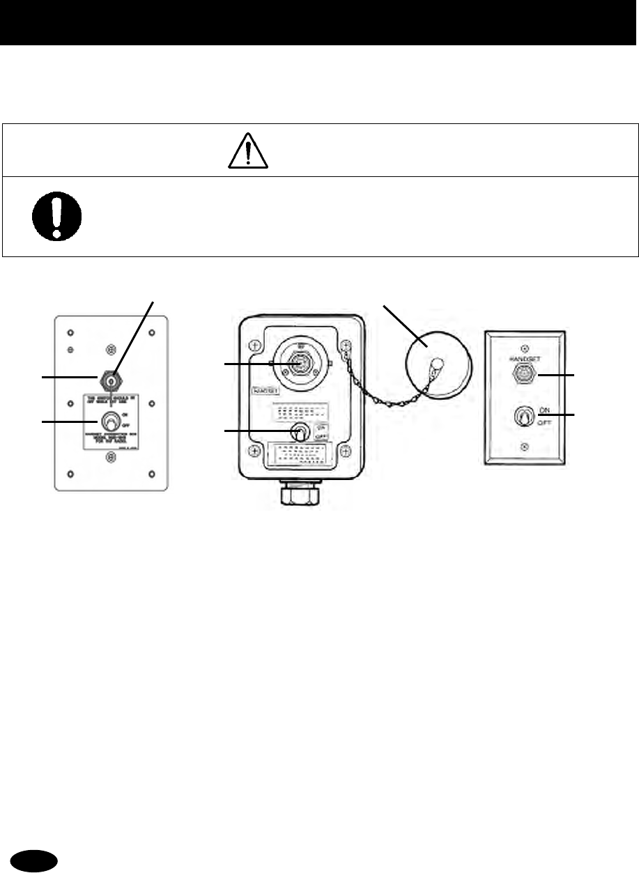
Options Operation
10-1
10. OPTIONS OPERATION
10.1 Handset connection box (NQE-1845/ 1846/ 1847)
There are three types of handset connection boxes: a waterproofed flush mount type for a wing console
(NQE-1845), a waterproofed wing installation type (NQE-1846) and an indoor flush mount type (NQE-1847).
CAUTION
Close the water-resistant cap of the waterproof type handset box after use. Rain and sea
breeze could cause connector malfunction. Also do not leave the handset above deck.
■ Procedure ■
1
1
1.
.
.
In the case of the waterproof type, remove the water-resistant cap.
2
2
2.
.
.
Connect the handset (NQW-261) to the connector.
3
3
3.
.
.
Turn ON the switch to start communications.
The access right will be obtained by turning on this switch.
(This switch is equivalent to hook switch of the handset.)
・ Always turn off the switch when not in use.
・ Even if the switch is turned on, while another controller with higher priority will be in use,
the access right will not be obtained.
Waterproofed
wing installation type
(NQE-1846)
Indoor flush mount type
(NQE-1847)
Note
1
2
3
1
2
1
2
3
1. Connector
2. Switch
3. Waterproof cap
Waterproofed
flush mount type
for wing console
(NQE-1845)
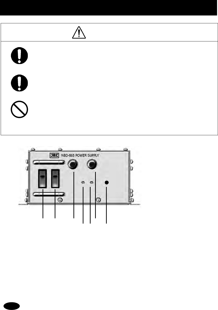
Options Operation
10-2
10.2 AC/DC Power supply (NBD-865)
WARNING
Before replacing fuses of this unit, always turn off this AC/DC power switch and power
source output to this unit.
Always use the specified fuse when replacing a fuse. Using a different fuse may result
in fire or malfunction.
In addition to the AC fuse on the panel, there are also DC fuses contained in the unit.
Opening and working with the inside of the unit may result in fire or electrocution, so with
the exception of qualified service personnel, do NOT attempt to replace the DC fuses.
To replace the DC fuses, contact JRC or our agent.
■ Procedure ■
1
1
1.
.
.
Turn on both of the AC and DC switches.
If there is no AC power connected, only turn on the DC power switch.
2
2
2.
.
.
Confirm that the DC OUTPUT lamp is lit.
If this lamp is lit, 24VDC power is being output properly.
・ If the switch is turned on but the DC OUTPUT lamp does not light, except for the dimmer control
position, there may be a malfunction with the AC/DC input power voltage, or a fuse may have
been blown.
・ If only DC power is used, the DC OPERATION lamp will light. Be careful not to over discharge
the battery.
1 2
1. AC Switch
2. DC Switch
3. AC Fuse (u)
4. DC OUTPUT Lamp
5. DC OPERATION Lamp
6. AC Fuse (v)
7. Dimmer control
4 5
3 6
Note
7
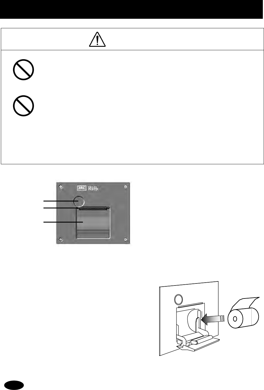
Options Operation
10-3
10.3 Printer (NKG-91)
CAUTION
The thermal head of the printer may be very hot after printing. Do not touch it.
Perform paper replacement and head cleaning only after waiting for the head to
completely cool.
The printing paper used in this printer is a heat sensitive paper. Take the following
precautions when using this paper.
· Store the paper away from heat, humidity, or heat sources.
· Do not rub the paper with any hard objects.
· Do not place the paper near organic solvents.
· Do not allow the paper to come in contact with polyvinyl chloride film, erasers, or
adhesive tape for long periods of time.
· Keep away the paper from freshly copied diazo type or wet process copy paper.
■ Loading the printer paper ■
1
1
1.
.
.
Press the paper cover open button.
The paper cover will open.
2
2
2.
.
.
Insert the paper as shown in the diagram at right.
Position the paper such that the edge extends outside the
printer, and press the both sides of the paper cover to
close it.
The printer will be turned on and off simultaneously with the radiotelephone.
1
2
3
1. Paper cover open button
2. Paper cutter
3. Paper cover
Note
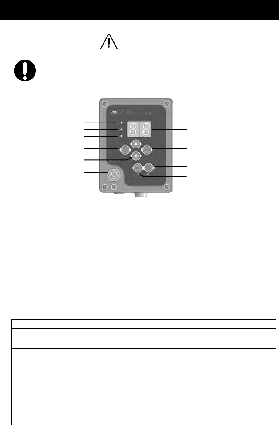
Options Operation
10-4
10.4 VHF Channel selector (NCM-2000)
CAUTION
For channel selectors installed above deck, close the water-resistant cap after use. Rain
and sea breeze could cause connector malfunction. Also do not leave the handset
above deck.
1. TX Lamp
Lights when transmitting.
2. 1W Lamp
Lights when transmitting power is 1W.
3. OCC Lamp
Lights when not having the access right.
4. 25W/1W Switch
Switches transmitting power between 25W and 1W. If pressed and held for two seconds, this unit becomes
to the menu mode. In this mode, select the desired item with the ▲ or ▼ key and press ENT, then perform
the procedure in the table below. When finishing this menu mode, press and hold for two seconds again.
Display Setting Setting Method
S.1 Squelch level Select 01 (open) - 32 with the ▲ or ▼ key, and press ENT.
S.2 PHONE level Select 01 - 08 with the ▲ or ▼ key, and press ENT.
S.3 Hook switch detection function Select ON/OFF with the ▲ or ▼ key, and press ENT.
S.4 Fine brightness
1) Select a brightness level from bright (d.1), medium
(d.2), or dark (d.3) with the ▲ or ▼ key, and press
ENT.
2) Select the fine brightness value (01-10) for the
brightness level selected in 1) with the ▲ or ▼ key,
and press ENT.
S.5 Software version Display a software version.
S.0 (Ends the menu mode.) -----
1
2
3
4
5
6
8
7
9
10
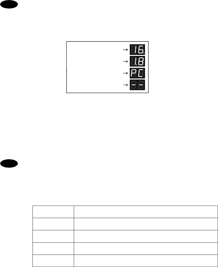
Options Operation
10-5
5. UP/DOWN arrow keys
These keys are used for channel selection, or menu settings.
6. Waterproof connector cap
When using this unit, remove this cap and connect the handset to the internal connector.
7. Display
Displays the current channel, menus, etc.
・ A lower right dot lights up at the time of squelch opened.
・ A lower middle dot lights up at the time of selection of duplex-channel.
・ Private channel and weather channel cannot be changed.
・ When weather channel, PA use, intercom use and such as unlock alarm occurred, display
will be “- -”.
• Squelch open
• Duplex channel
• Private channel
• Weather channel, etc.
8. CH16 key
Sets the radiotelephone channel to CH16.
9. PWR/ENT key
In addition to turning on the power, this key is used to determine the menu items, or to obtain the access right.
10. DIM (brightness control) key
This key cycles the display brightness between bright, medium, dark, and off. If pressed at the same time as
the PWR/ENT key, it activates sleep mode.
・ The brightness level will not be saved. So when the unit is powered off and on, this level
will be at the default medium setting.
・ The channel selector cannot change the channel region mode (ITU/USA/Canada/Inland
Waterway). When changing the channel region mode, use the controller (NCM-1770).
・ The following alarm will be displayed if an error is detected in the channel selector.
When the alarm is displayed, contact JRC or our agency.
Alarm Number Contents
E1 Detected the memory (ROM1) error.
E2 Detected the memory (ROM2) error.
E3 Detected the serial communication test error at powering on.
E4 Detected the serial communication error.
Note
Note
Options Operation
10-6