Japan Radio CMN727B WLAN MODULE User Manual
Japan Radio Co Ltd. WLAN MODULE
Contents
- 1. (CMN-727B) UserMan
- 2. UserMan
- 3. user manual
user manual
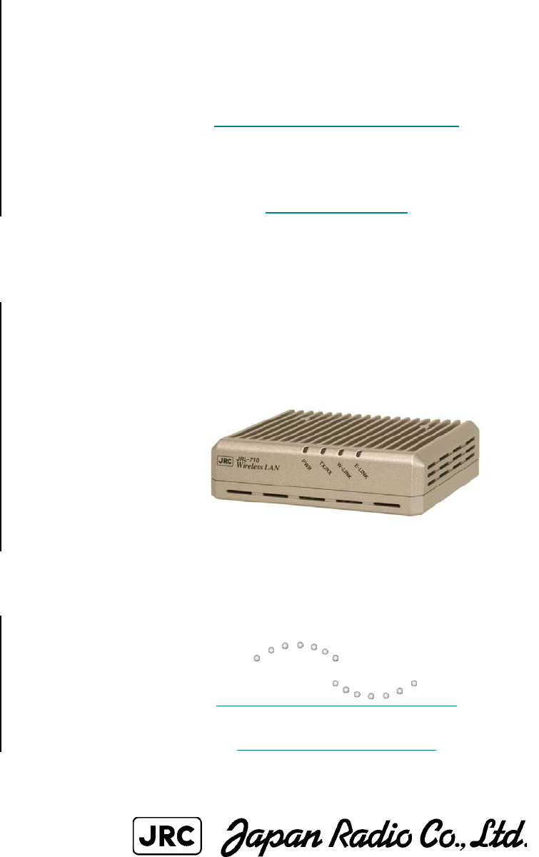
Wireless LAN
JRL-710AP3R
Manual
Global Communications
http://www.jrc.co.jp

2/12
Please read a user's manual about the command for setting change,
display, and examination of this equipment.
3/12
Compliance statement and notification
<FCC / IC>
RF exposure compliance:
This equipment complies with FCC/IC radiation exposure limits set forth for an
uncontrolled environment and meets the FCC radio frequency(RF)Exposure
Guidelines in Supplement C to OET65 and RSS-102 of the IC radio frequency(RF)
Exposure rules. This equipment has very low levels of RF energy that it deemed to
comply without maximum permissive exposure evaluation(MPE). But it is desirable
that it should be installed and operated keeping the radiator at least 20cm or more
away from person’s body(excluding extremities: hands, wrists, feet and ankles).
CAUTION
Changes or modifications not expressly approved by the party responsible for
compliance could void the user’s authority to operate the equipment.
Declaration of Conformity
Product Name: Wireless Lan
Model Number: JRL-710AP3R
This device complies with Part 15 of FCC Rules and RSS-Gen of IC Rules. Operation
is
subject to the following two conditions:
(1) this device may not cause harmful interference, and
(2) this device must accept any interference, including interference that may cause
undesired operation of this device.
4/12
< FCC >
NOTE: This equipment has been tested and found to comply with the limits for a Class B
digital device, pursuant to part 15 of the FCC Rules. These limits are designed to provide
reasonable protection against harmful interference in a residential installation. This
equipment generates, uses and can radiate radio frequency energy and, if not installed and
used in accordance with the instructions, may cause harmful interference to radio
communications. However, there is no guarantee that interference will not occur in a
particular installation. If this equipment does cause harmful interference to radio or
television reception, which can be determined by turning the equipment off and on, the user
is encouraged to try to correct the interference by one or more of the following measures:
-Reorient or relocate the receiving antenna.
-Increase the separation between the equipment and receiver.
-Connect the equipment into an AC outlet on a circuit different from that to which the
receiver is connected.
-Consult the dealer or an experienced radio/TV technician for help.
In according with 47 CFR Part15.407 (e) U-NII devices operating in 5.15-5.25GHz
frequency bands are restricted to indoor operations only.
This transmitter must not be co-located or operated in conjunction with any other
antenna or transmitter.
< IC >
Operation is subject to the following two conditions:
(1) this device may not cause interference, and
(2) this device must accept any interference, including interference that may cause
Undesired operation of the device.
Canada, avis d'Industry Canada (IC)
Cet appareil numérique de classe B est conforme aux normes canadiennes ICES-003 et
RSS-210.
Son fonctionnement est soumis aux deux conditions suivantes : (1) cet appareil ne doit pas
causer d'interférence et (2) cet appareil doit accepter toute interférence, notamment les
interférences qui peuvent affecter son fonctionnement.
Informations concernant l'exposition aux fréquences radio (RF)
La puissance de sortie émise par l’appareil de sans fil est inférieure à la limite d'exposition
aux fréquences radio d'Industry Canada (IC). Utilisez l’appareil de sans fil de façon à
minimiser les contacts humains lors du fonctionnement normal.
Ce périphérique a également été évalué et démontré conforme aux limites d'exposition aux
RF d'IC dans des conditions d'exposition à des appareils mobiles (les antennes se situent à
moins de 20 cm du corps d'une personne).

5/12
<R&TTE>
CE Marking:
Please describe the following sentences to the label or the user manual of the
product in each language in the sales country:
Hereby, Japan Radio CO., Ltd. declares that this JRL-710AP3R is in
compliance with the essential requirements and other relevant provisions
of Directive 1999/5/EC.
6/12
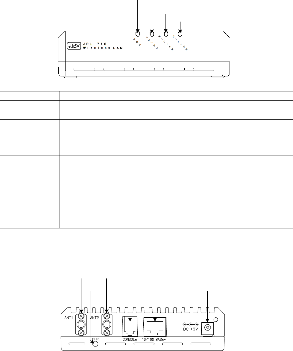
1.The name of each part
● Front side
① P W R
② T X /R X
④ E -L INK
③ W -L INK
Name Remarks
① PWR If a power supply is supplied to this equipment, the light will be
switched on in "green."
② TX/RX
"Orange": Switch on the light during transmission.
"Green": Switch on the light during reception.
In STA, lighting "green" and "orange" is periodically repeated
during AP search.
③ W-LINK
The light is switched on while STA connects with AP.
The light is switched on during STA connection by "orange":AP
setup.
The light is switched on during AP connection by "green":STA
setup.
④ E-LINK The light is switched on when EtherNet links.
"Orange" : The light is switched on in LINK as 10BASE-T.
"Green" : The light is switched on in LINK as 100BASE-TX.
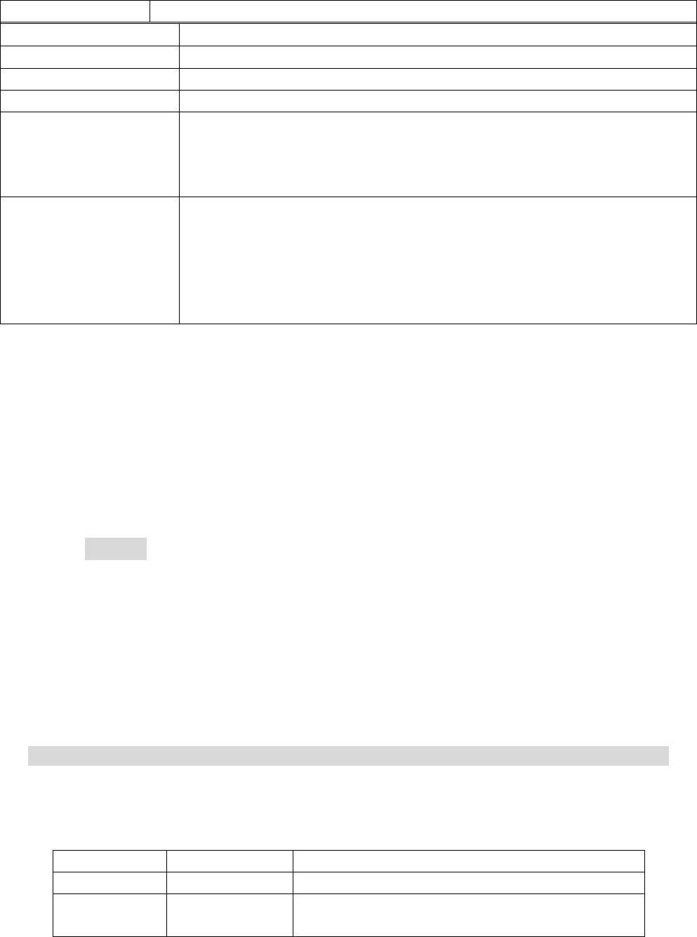
● Back side
⑤ ANT1
⑨ D C +5 V
⑧ 10/100BASE-T
⑥ A N T 2
⑦ C O N S O L E
⑩ C L R
7/12
Name Remarks
⑤ ANT1 It is a connector which connects an antenna.(Main)
⑥ ANT2 It is a connector which connects an antenna.(Sub)
⑦ CONSOLE It is a connector which connects maintenance PC.
⑧ 10/100BASE-T It is a connector which connects Ethernet.
⑨ DC +5V
A power supply is connected and a power supply is
supplied to equipment.
This connection is unnecessary when supplying a power
supply by PoE.
⑩ CLR
It is a switch which initializes a setup.
The power supply of this equipment is switched on
pushing the "CLR" button.
If it is continuing pushing the "CLR" button, the "PWR"
lamp will change from "green" to "orange" for 1 second.
Then, equipment returns to initial setting.
2.Login
The IP address initial value of wireless LAN is set as "192.168.1.1/24."
Here, the login method in case the IP address of this equipment is
"192.168.1.1/24" is shown.
Please read a user's manual about the command for setting change,a
display, and an examination of this equipment.
①Login
PC which logs in to this equipment is prepared.
The IP address of PC is changed into "192.168.1. x/24" so that PC
can communicate with this equipment. However, the value of "x" is
2 to 254.
②PC If a setup of PC is completed, this equipment will be connected
with PC by cable. If it connects with PC normally, the "E-LINK" lamp
will light up.
(1) User account
The following user names and passwords are set up in the initial state.
Please change a password at the time of the first login for security
protection.
User name Password Authority
admin admin Setting change / setting display
user user Setting change (only password) / setting
display
8/12
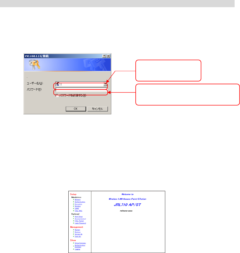
(2) Login
It logs in to this equipment using a WEB browser. If
"http://192.168.1.1" is inputted into the address of a WEB browser, it
will connect with this equipment and will display the following login
windows.
Login windows
A top screen will be displayed if it succeeds in login. Now, login to this
equipment is completion.
Please read a user's manual about the command for setting change,a
display, and an examination of this equipment.
Top screen
A
password is entered.
The entered password is displayed by "*."
A user name is inputted.
「admin」,「user」
9/12
【Specification】
1. General
1) Input Power : DC IN; DC 5V+/-5%
IEEE802.3af; DC48V (36 to 57V)
2) Frequency Range : 2.4GHz ISM band (2412 to 242MHz)
5GHz band(W52)(5150 to 5250MHz)
3) Radio Communication Standard : IEEE802.11a/b/g
4) Operating Temperature : -30 to +65 degree C
5) Power Consumption : Less than 5W
2. Electrical Specification
1) Output Power : 8mW/MHz +20%, -80%(2.4GHz band)
3mW/MHz +20%, -80%(5GHz band(W52))
2) Number of Channel :
2.4GHz band; 13-channels
CH1: 2412MHz, CH2: 2417MHz, CH3: 2422MHz, CH4: 2427MHz,
CH5: 2432MHz, CH6: 2437MHz, CH7: 2442MHz, CH8: 2447MHz,
CH9: 2452MHz, CH10: 2457MHz, CH11: 2462MHz
5GHz band; 4-channels
CH36:5180MHz, CH40:5200MHz, CH44:5220MHz, CH48:5240MHz,
3) Channel Separation : 5MHz(2.4GHz band)
20MHz(5GHz band(W52))
4) Modulation : DSSS/OFDM
5) Access Method : Carrier Sense Multiple Access (CSMA)
6) Variable method of Transmission rate
i) IEEE802.11b mode : Automatic : 1,2,5.5,11Mbps
: Fixed : 1,2,5.5 or 11Mbps
i) IEEE802.11ag mode : Automatic :
6,9,12,18,24,36,48,54Mbps
: Fixed : 6,9,12,18,24,36,48, or 54Mbps
10/12
7) Band Width : Less than 26MHz(2.4GHz band)
Less than 19MHz(5GHz band(W52))
8) Wire connection interface : IEEE802.3 (CSMA/CD), 10/100Base-T
9) Antenna Impedance : 50ohms
10) Number of Terminal Capacity
a. Wireless Terminal : 127 terminals
b. Wired Terminal : 1024 terminals
3. Mechanical Specification
1) Antenna Connector : SMA-RP
2) 10/100Base-T Connector : RJ-45
3) Antenna Connection Port : Two (2) port (One is for
Diversity)
4) LED Indicator : a) Main power indicator
b) Tx/Rx indicator
c) Wireless LAN link indicator
d) Wired LAN link indicator
5) Clear Key (Reset) Switch : Factory default mode
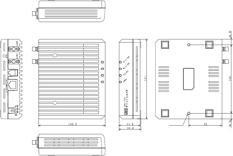
6) Dimension : 121(W) x 32.8(H) x 100.5(D) mm
7) Weight : Approx. 400g
4. Support Function
1) Wireless Bridge
2) Roaming
3) SNMP (Simple Network Management Protocol)
4) Remote Monitoring
5) WEB Log In
6) Telnet Log In
7) Diagnostic Command
11/12
5. Security
1) 32 Characters ESSID (Extended Service Set ID)
2) Any ID Cancellation
3) SSID Stealth (Mask in Beacon)
4) MAC Address Filtering
5) Access Filter
6) WEP (Wired Equivalent Privacy) RC4 Algorithm (40/104/128bits)
7) WPA (Wi-Fi Protected Access)-PSK
i) TKIP
ii) AES
8) Packet Filter
9) IEEE802.11i
6. Outline Drawing
CONSOLE
2-M4 Depth-8

12/12
2.4 GHz/5.2GHz band wireless LAN module
JRL-710AP3R
Manual
Do not copy
February 1, 2013
Japan Radio Co., Ltd.
Mobile communication group
1-1 SHIMORENJAKU 5 CHOME, MITAKA-SHI, TOKYO, JAPAN
Tel +81-422-45-9236,Fax +81-422-45-9880