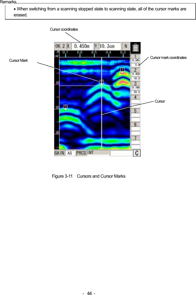
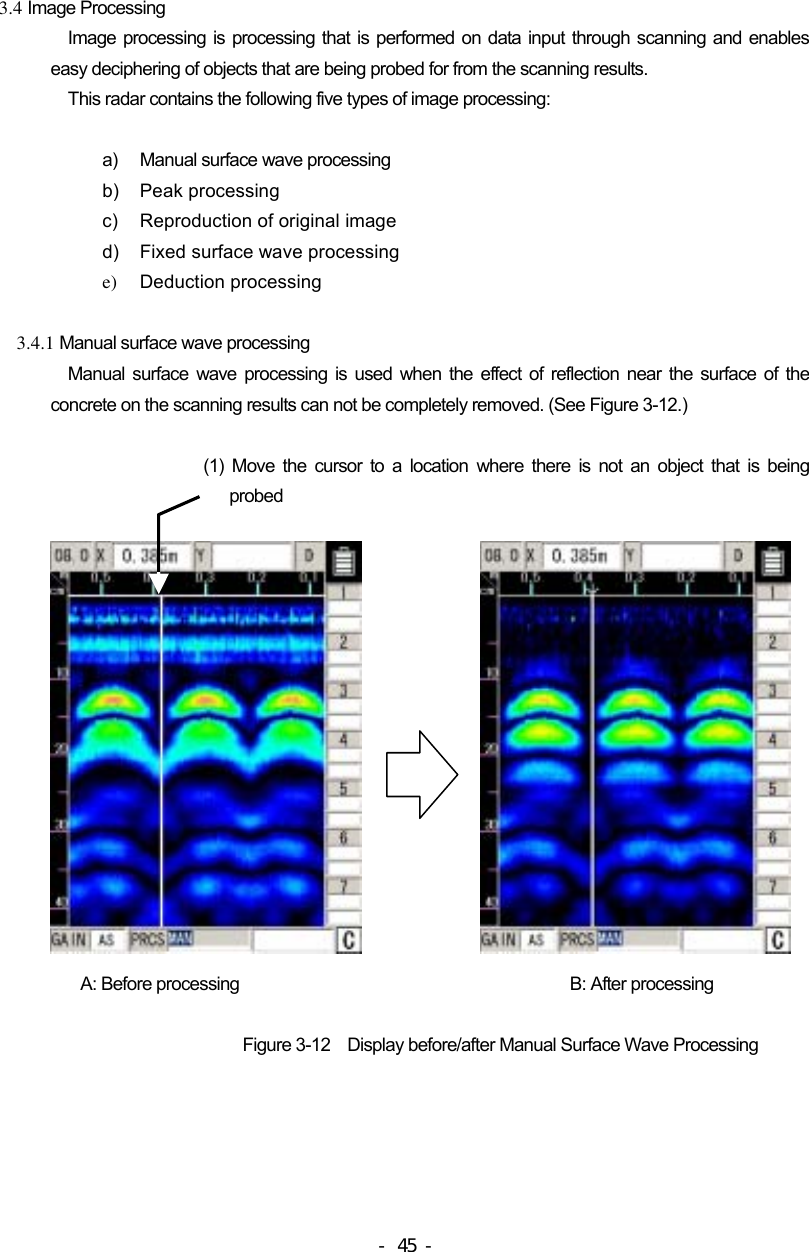
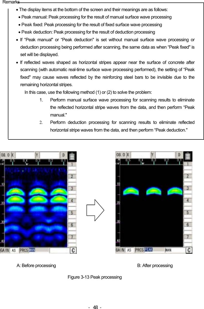
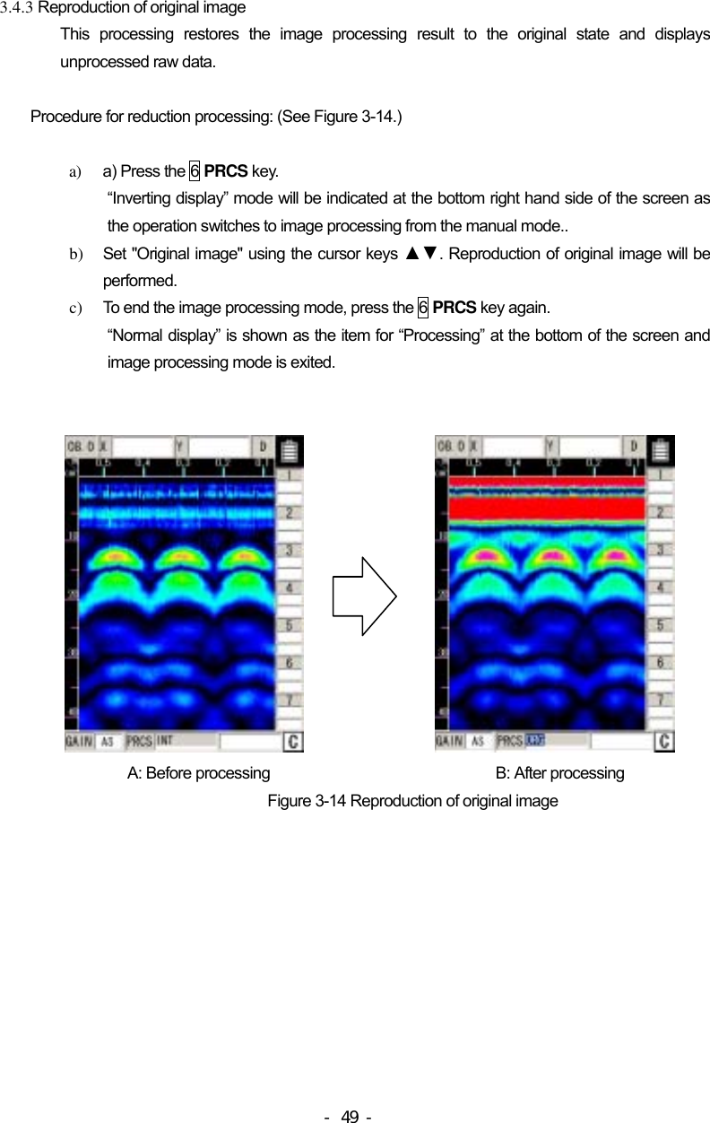
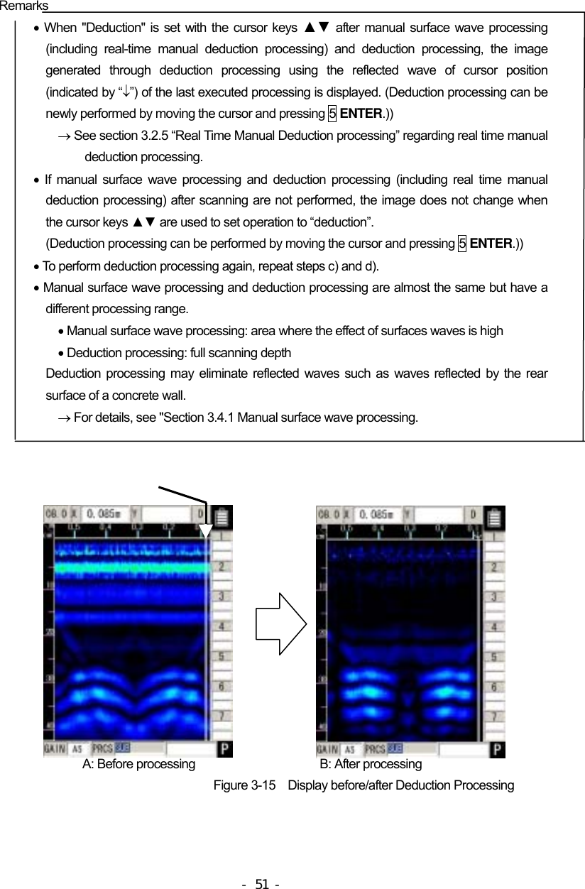
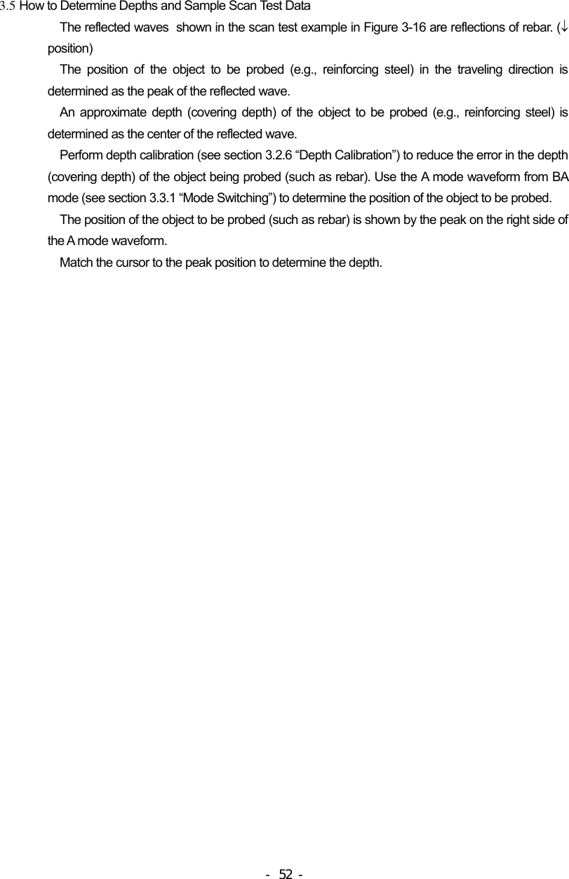
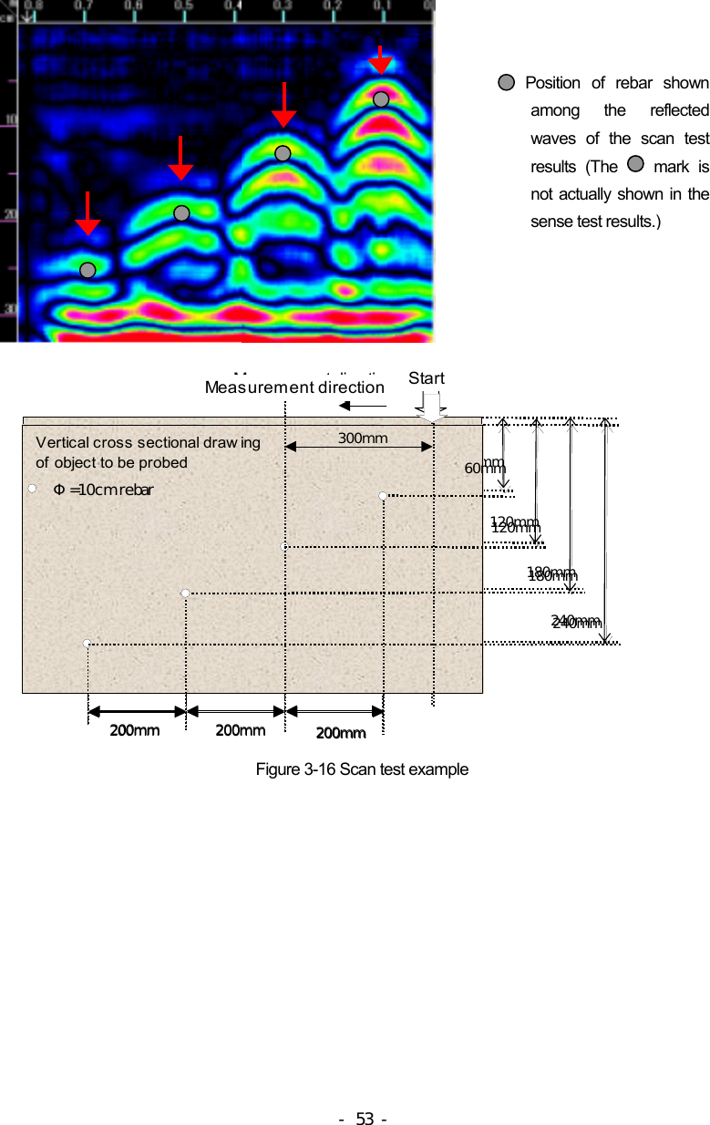
Japan Radio HANDYSEARCH Ground penetrating radar User Manual
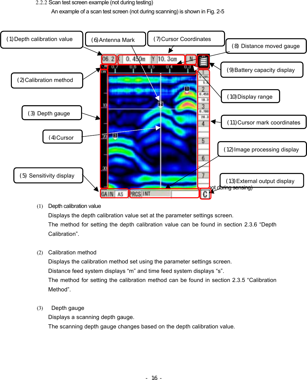
Japan Radio Co Ltd. Ground penetrating radar Users Manual
UserManual.wiki
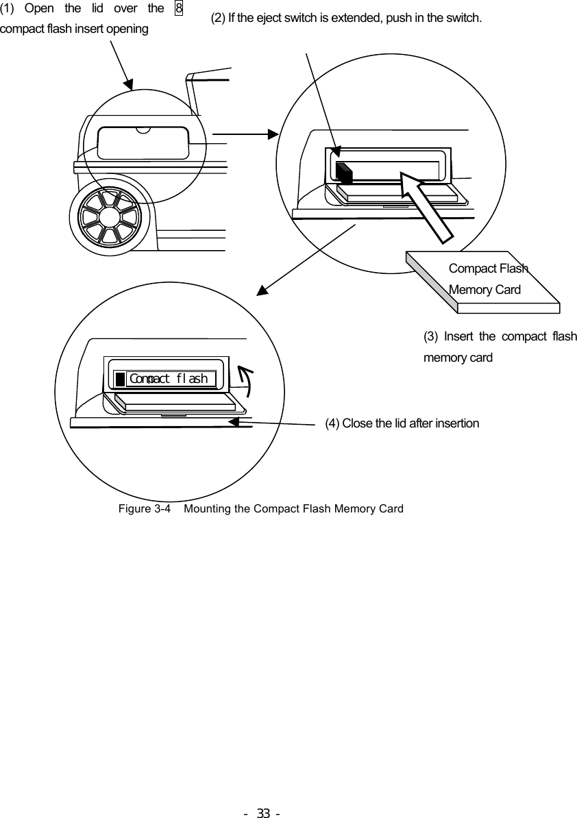
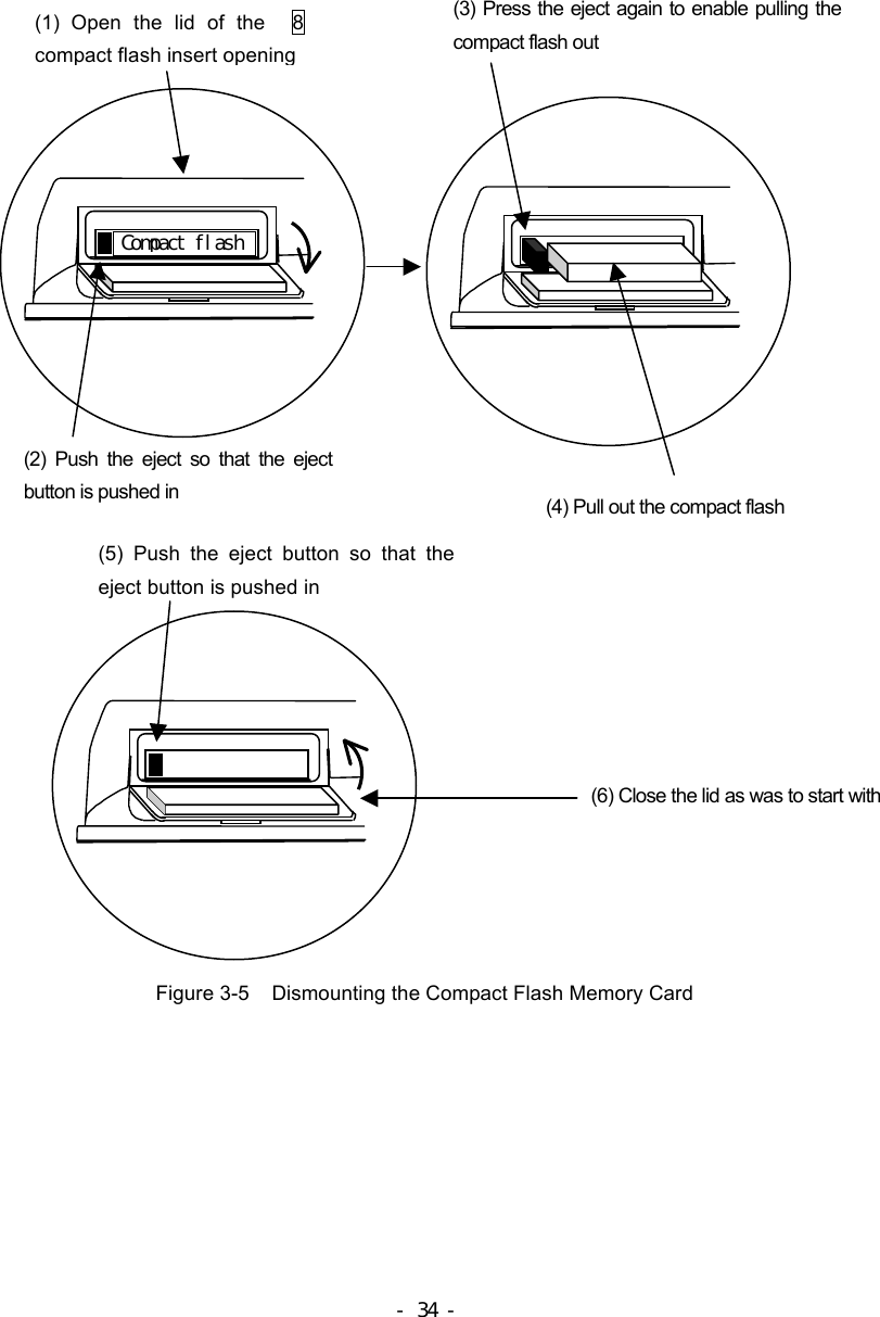
>
Japan Radio
>
HANDYSEARCH User Manual
>
Manual
Contents
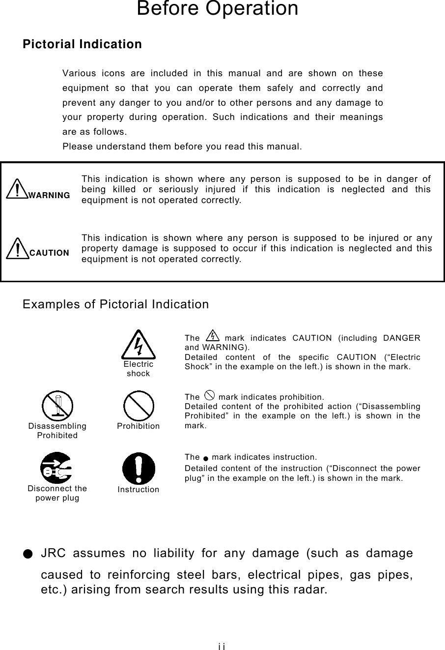
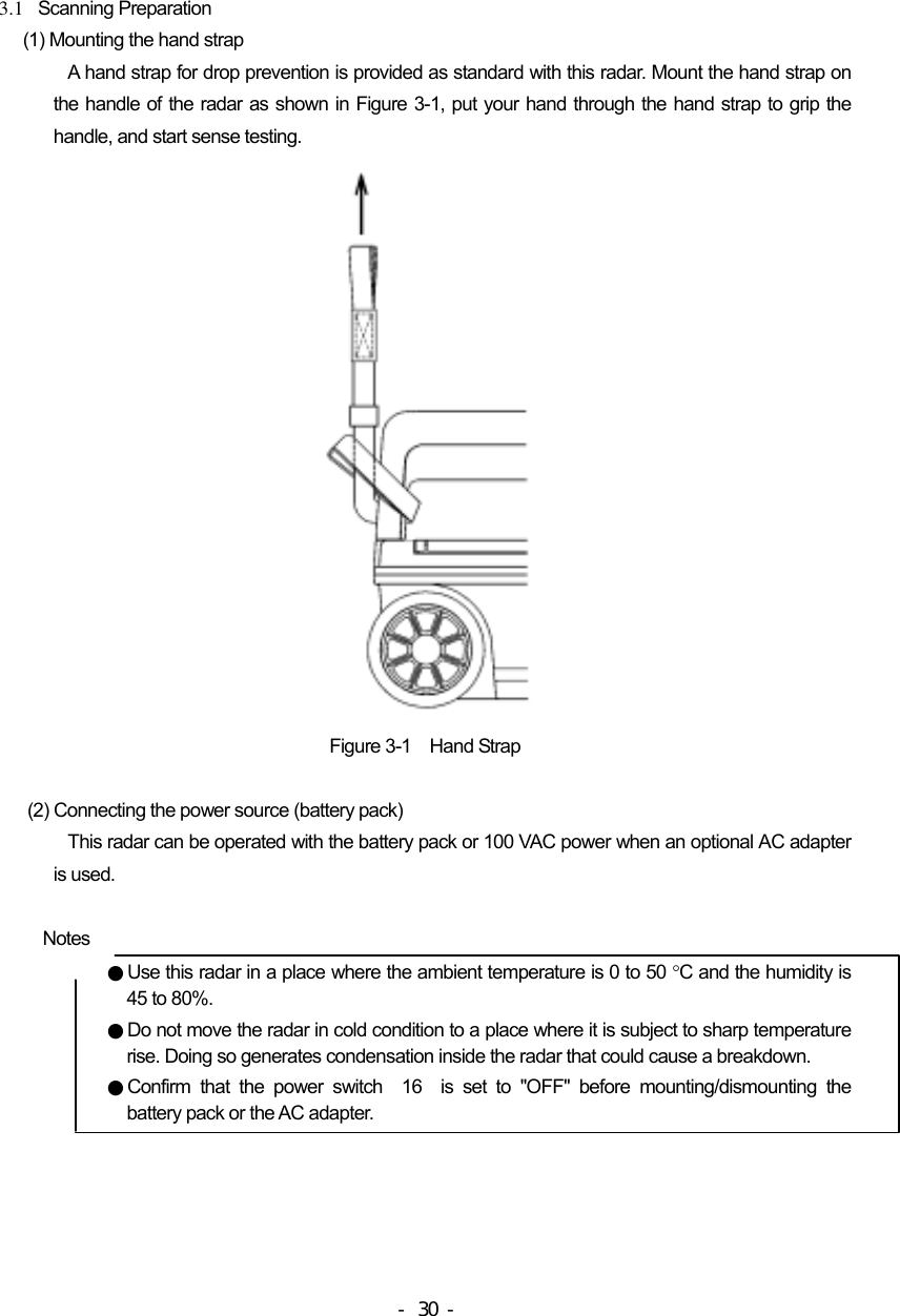
1.
Manual
2.
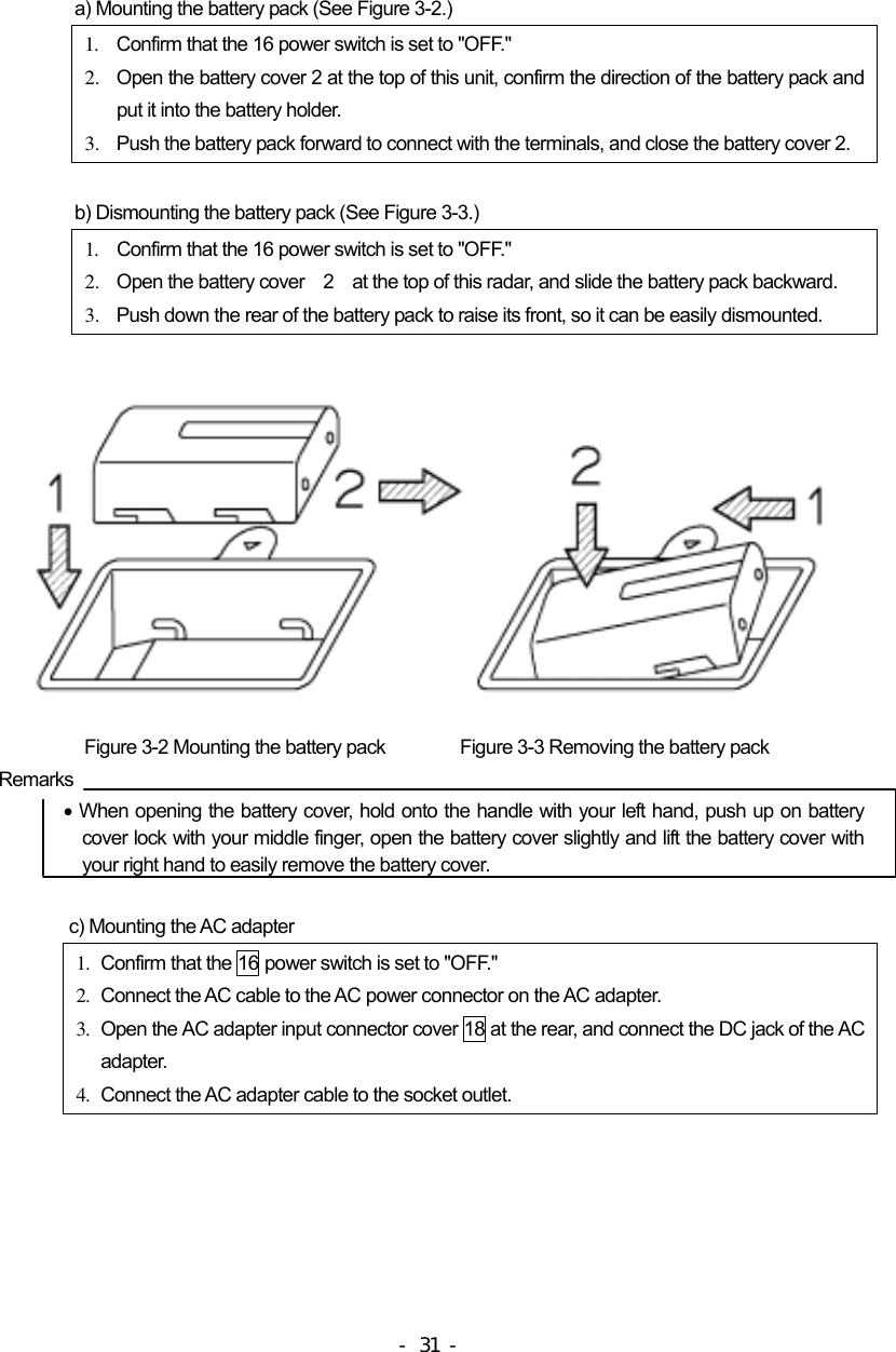
pamphlet 1
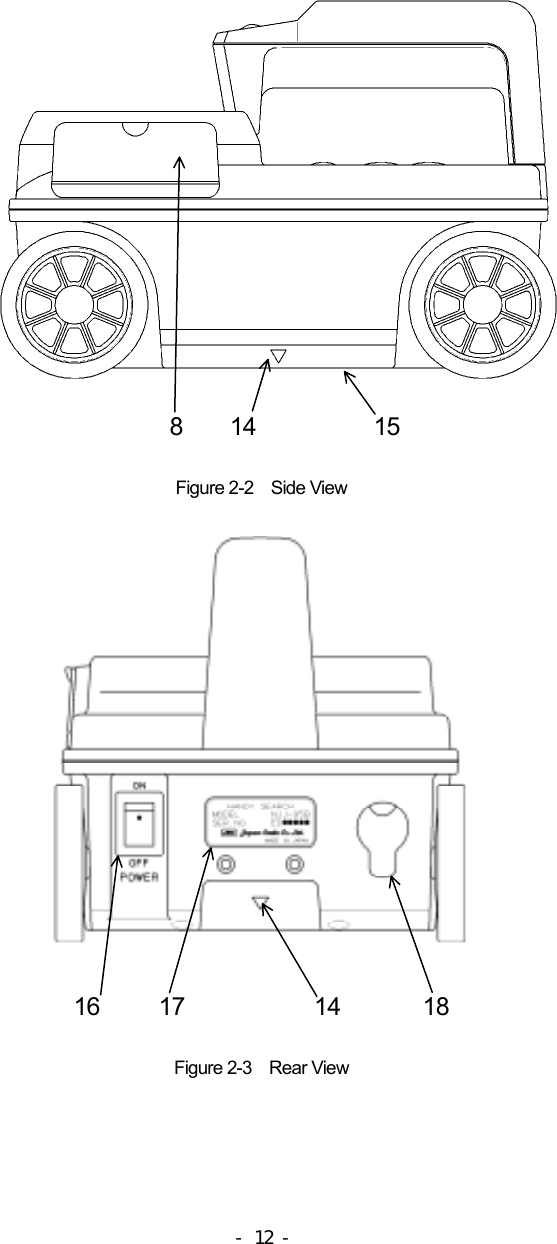
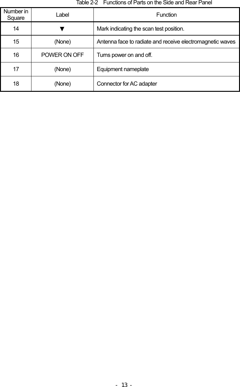
3.
pamphlet 2
Manual
Navigation menu
Upload a User Manual
Namespaces
Wiki Guide
HTML
PDF
Info
Views
User Manual
Discussion / Help
Navigation
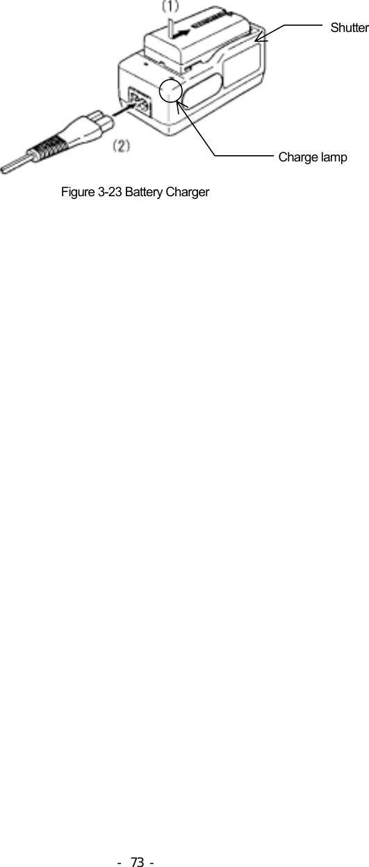
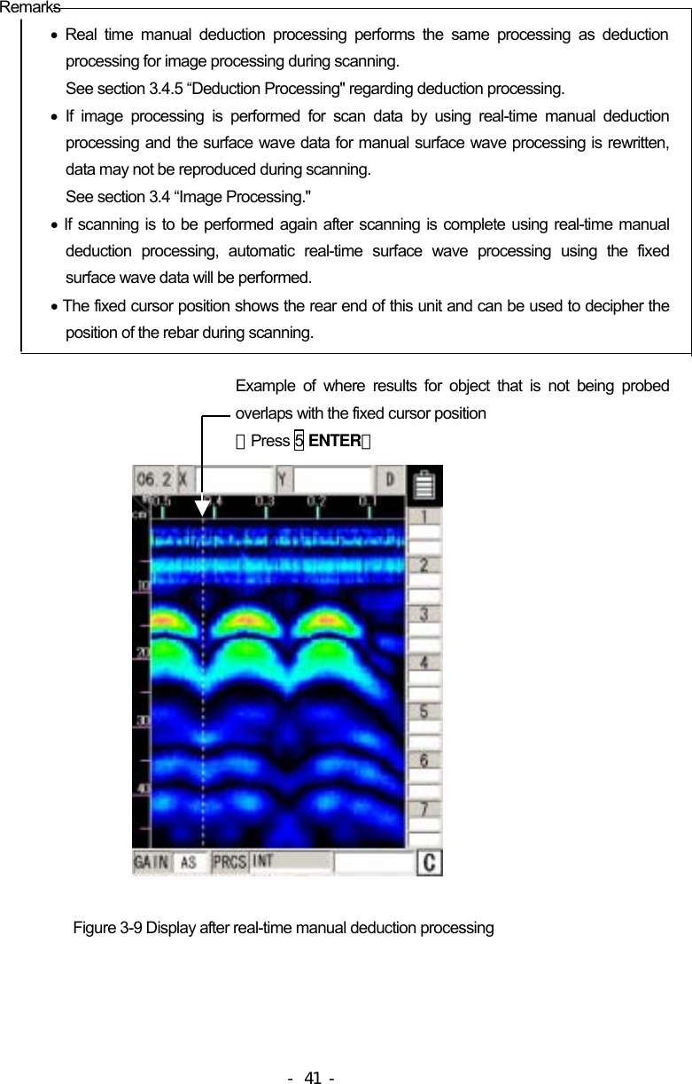
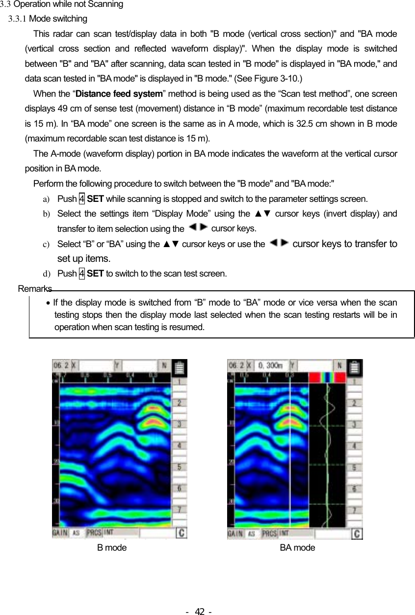
![Rear view [Units in trigonometry: mm] - 9 -](https://usermanual.wiki/Japan-Radio/HANDYSEARCH.Manual/User-Guide-858722-Page-21.png)
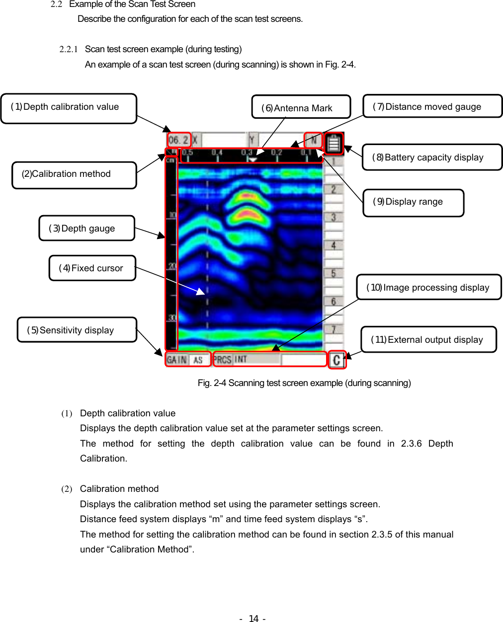
![2.3 Parameter Settings Screen While scanning is stopped, pressing of the 4 SET key enables switching the screen to the parameter settings screen (see Fig. 2-6) and each of the settings can be changed. To return to the scanning test screen, press the 4 SET key again. Selections Settings [Left column] [Right column] Display color Color Screen inversion Normal Display Mode B Level adjustment method Absolute value Measurement method Distance feed Depth calibration 06.2 [-3] Date 2006/07/21 18:09 Data No. 005 Distance correction +0 [0.00 m] External output CF [binary] Display range Depth Character mode Japanese Return to standard No Figure 2-6 Parameter Setting Screen 2.3.1 Display color "Color" or "Monochrome" can be selected for the display color for the liquid crystal display of the - 19 -](https://usermanual.wiki/Japan-Radio/HANDYSEARCH.Manual/User-Guide-858722-Page-31.png)
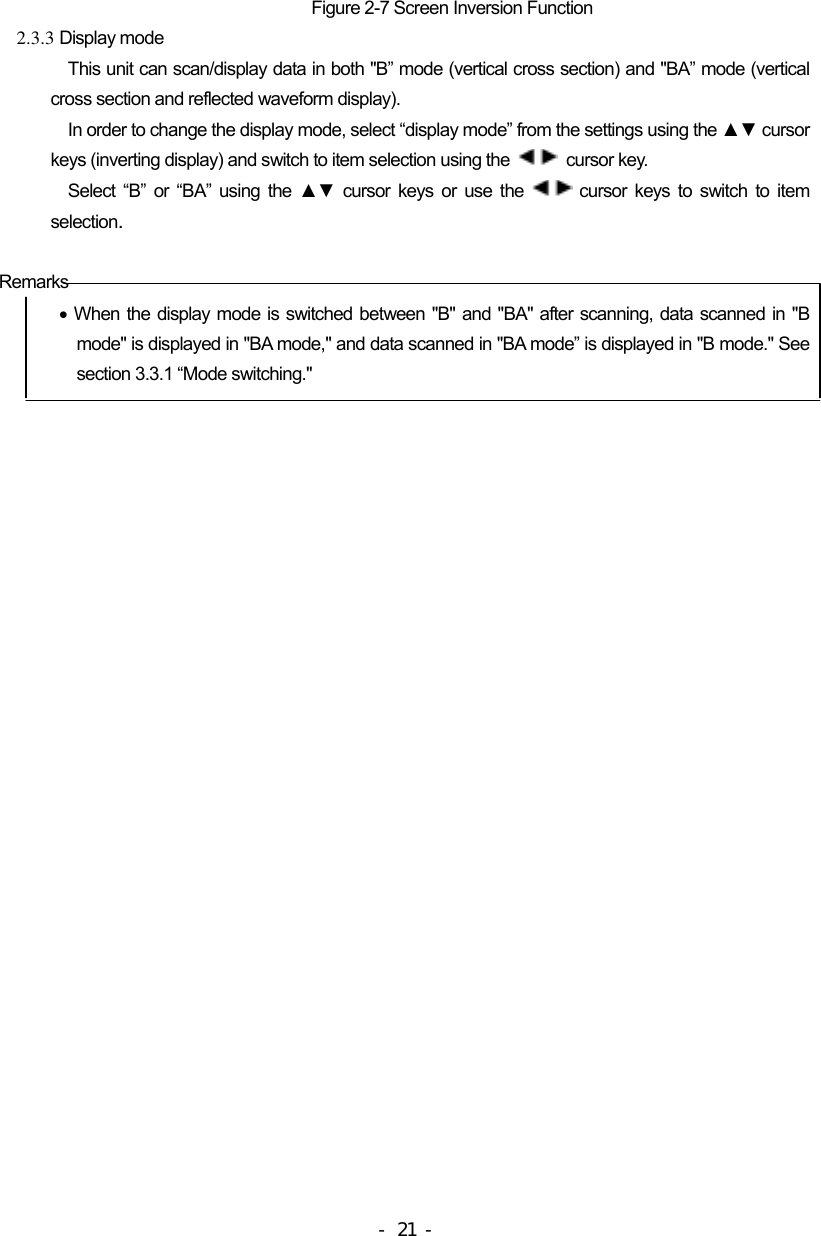
![main unit. In order to change the display color, select “display color” from the settings using the ▲▼ cursor keys (inverting display) and switch to item selection using the cursor keys. Select “color” or “monochrome” using the ▲▼ cursor keys or use the cursor keys to switch to item selection. 2.3.2 Inversion of the screen This unit supports screen display inversion while it moves (scans) to the right and to the left, thereby displaying the scanning test screen upside down. (See Figure 2-7.) In order to invert the screen, select “Invert Screen” from the set up items using the ▲▼ cursor keys (invert display) and switch to item selection using the cursor keys. Select “normal” or “inverted” using the ▲▼ cursor keys or use the cursor keys to switch to item selection. Remarks The direction of image data output by the printer (optional) is changed depending on the setting of the screen inversion function. For the printer to always output image data in the same direction, retain the same setting "Normal or Reverse" for "Inversion of the screen." • While the screen display is inverted, the cursor keys ▲▼ move in the opposite direction. (They function in the same direction as when "Normal" is selected for "Inversion of the screen.") Screen display direction [Normal] Screen display direction [Reverse] - 20 -](https://usermanual.wiki/Japan-Radio/HANDYSEARCH.Manual/User-Guide-858722-Page-32.png)
![2.3.8 Data No. Data is recorded and numbered when externally output. The data number (Data No.) is incremented each time data is recorded. In order to change the data No., select “Data No.” from the set up items using the ▲▼ cursor keys (invert display) and switch to item selection using the cursor keys. Select the position that you would like to correct using the cursor keys and change the values using the ▲▼ keys. Switch to item selection using the keys. Remarks When data is to be recorded again, it can be easily managed by changing the value of Data No. 2.3.9 Distance compensation This unit determines distance using the number of rotations the wheels make. Thus, wear of the wheels causes an error in calculating the scanning distance. If the scanning distance has an error, compensate the distance error. In order to change the distance error correction value, select “Distance Correction” from the set up items using the ▲▼ cursor keys (invert display) and switch to item selection using the cursor keys. Set the “distance error correction value” using the ▲▼ cursor keys and use the cursor keys to switch to item selection. (Example of distance error compensation) a) Perform a 1m (actual value) scan test and stop the scanning. b) Press the 4 SET key and switch to the parameter settings screen c) Select the settings item “Distance Correction” using the ▲▼ cursor keys (invert display) and switch to item selection using the cursor keys. d) d) Using the ▲▼ cursor keys, set the correction value so that the distance of the last line (displayed by [ ] to the right of the correction value) is as close as possible to 1 m. e) Use the cursor keys to switch to item selection and press the 4 SET key to return to the scan test screen. Remarks ● The distance of the last scan test line is displayed to the right of the compensation value. When the compensation value is changed, the distance is also changed in accordance with the new compensation value. With this value as a rough standard, set a new compensation value. - 24 -](https://usermanual.wiki/Japan-Radio/HANDYSEARCH.Manual/User-Guide-858722-Page-36.png)
![2.3.10 Output Data Format Set the external output destination of scan test data. The table below shows the relationship between external output destinations and output data formats. The currently set external output destination is indicated with the character displayed at the lower right of the scan test screen. External Output Destination Output Data Format Scan Test Screen Destination on Measurement Screen Printer (I) Print to the printer CF [text] Saved in text format in compact flash memory CF [binary] Saved in binary format in compact flash memory In order to change external output, select “External Output” from the set up items using the ▲▼ cursor keys (invert display) and switch to item selection using the cursor keys. Set the “external output” using the ▲▼ cursor keys and use the cursor keys to switch to item selection. See Section 3.6 External Output Methods for the operation method. 2.3.11 Display Range The display range is an item for setting the display limits of the scanning depth. There are three settings: “deep”, “standard”, and “shallow”. Set the range of display based on depth of the object to be scanned using the following. Depth of the object to be scanned is 30 cm or less: “deep” The depth of the object to be scanned is 20cm or less: “standard” (same as NJJ-95A) Depth of the object to be scanned is 10cm or less: “shallow” In order to change the display range, select “display range” from the settings using the ▲▼ cursor keys (inverting display) and switch to item selection using the cursor key. Set the “display range” using the ▲▼ cursor keys and use the cursor keys to switch to item selection. 2.3.12 Character Mode Switches displayed characters between Japanese and English. In order to change the character mode, select “Character Mode” from the settings using the ▲▼ cursor keys (inverting display) and switch to item selection using the cursor key. Set the type of characters using the ▲▼ cursor keys and use the cursor keys to switch to item selection. - 25 -](https://usermanual.wiki/Japan-Radio/HANDYSEARCH.Manual/User-Guide-858722-Page-37.png)
![b) Header section The following shows a sample configuration of the header section and explains the items. The control codes in the header section are as follows: [0x0D] = CR, [0x0A] = LF, and [0x1A] = EOF. Sample configuration of the header section: (1)NJJ-95 B Measurement Data ###[0x0D][0x0A] (2)Date : 31.12.06[0x0D][0x0A] (3)Time : 23:59[0x0D][0x0A] (4)Data # : 999[0x0D][0x0A] (5)X Data Size : 3000[0x0D][0x0A] (6)Y Data Size : 512[0x0D][0x0A] (7)X Scale : Distance[0x0D][0x0A] (8)Y Scale : 06.2[0x0D][0x0A] (9)X Scale Adjust : +5[0x0D][0x0A] (10)Y Scale Range: 6ns[0x0D][0x0A] (11)MarkX 1 : 3[0x0D][0x0A] (12)MarkY 1 : 14[0x0D][0x0A] (13)MarkX n : 2997[0x0D][0x0A] (14)MarkY n : 508[0x0D][0x0A] (15)END[0x0D][0x0A] (16)[0x1A] [0x0D][0x0A] Items in the header section: (1)ID data such as the model name (2)Date (3)Time (4)Data No.: 000 to 999 (5)Number of lines: 1 to 3000 (6)Number points per line: 512 (fixed value) (7)Scan test system: "Distance" for distance feed, and "Time" for time feed (8)Depth calibration value: 06.0 to 11.0, or ns (9)Distance error compensation value: -20 to +0 to +20 (10)Shows the display range when saving: shallow = 4ns, standard = 6 ns, deep = 8 ns (11) X coordinate of the 1st cursor marker: Shown by line No. (12) Y coordinate of the 1st cursor marker: Shows the point No. (13) X coordinate of the n-th cursor marker: Max. n = 7 - 57 -](https://usermanual.wiki/Japan-Radio/HANDYSEARCH.Manual/User-Guide-858722-Page-69.png)
![Details on 768 bytes of scan test data: Scan test data per line includes 512 points, and 1-point data consists of 12 unsigned bits. Two-point data is sent after being re-listed as 3 bytes, so a total of 512 points (= 768 bytes) are sent. Data is re-listed according to the rule shown below. [0xABC]+[0xDEF]→[0xAD]+[0xBC]+[0xEF] Following the fixed surface wave data, the single-line scan test data explained above is output for each scan test line. The header of the fixed surface wave data is [0xFF]. Therefore, the length of the data section is variable: (1 byte of header + 768 bytes of scan test data) x (number of scan test lines +1) (number of measurement lines + 1) (2) Text mode a) Configuration The data format of the text mode is the same as for the binary mode. The difference from the binary mode is that the text mode processes all data as ASCII data. Header section (ASCII data) + data section (ASCII data) b) Header section The configuration of the header section is the same as for the binary mode. c) Data section The text mode converts one byte of data output by the binary mode to two bytes of ASCII data (HEX) and outputs the converted data with [0x0D] and [0x0A] being added. Remarks • The size of data in binary mode is smaller than that in text mode, thereby saving space of the compact flash memory. • The saved data is A/D conversion data (original image data), but not the one after image processing such as surface wave processing has been performed. - 59 -](https://usermanual.wiki/Japan-Radio/HANDYSEARCH.Manual/User-Guide-858722-Page-71.png)