Japan Radio HANDYSEARCH Ground penetrating radar User Manual
Japan Radio Co Ltd. Ground penetrating radar Users Manual
Contents
- 1. Manual
- 2. pamphlet 1
- 3. pamphlet 2
Manual
NJJ−95B
Handy Search
Instruction Manual
Preface
Thank you very much for purchasing this JRC NJJ-95B Handy Search
The NJJ-95B RC radar nondestructively locates, detects, and displays the depths
and positions of reinforcing steel bars in reinforced concrete structures.
●Before attempting to operate the NJJ-95B, please read through this instruction
manual carefully to learn all of its features and ensure correct and trouble-free
operation.
●Keep the instruction manual handy for reference. Refer to the manual for
information about the NJJ-95B or when experiencing trouble during operation.
DC01-NJJ-95B
First edition September 2006
i
ii
Before Operation
Pictorial Indication
Various icons are included in this manual and are shown on these
equipment so that you can operate them safely and correctly and
prevent any danger to you and/or to other persons and any damage to
your property during operation. Such indications and their meanings
are as follows.
Please understand them before you read this manual.
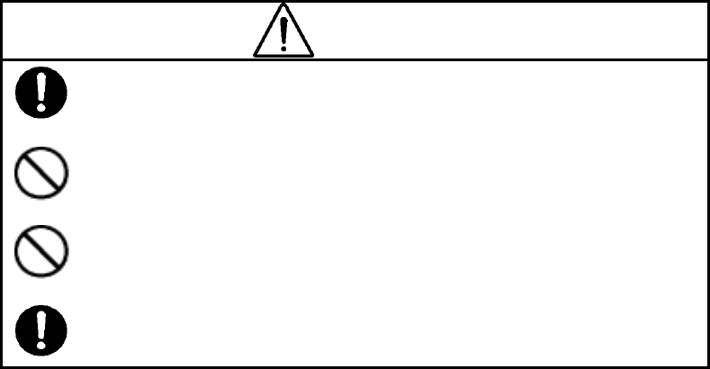
WARNING
This indication is shown where any person is supposed to be in danger of
being killed or seriously injured if this indication is neglected and this
equipment is not operated correctly.
CAUTION
This indication is shown where any person is supposed to be injured or any
property damage is supposed to occur if this indication is neglected and this
equipment is not operated correctly.
Examples of Pictorial Indication
Electric
shock
The mark indicates CAUTION (including DANGER
and WARNING).
Detailed content of the specific CAUTION (“Electric
Shock” in the example on the left.) is shown in the mark.
Disassembling
Prohibited
Prohibition
The mark indicates prohibition.
Detailed content of the prohibited action (“Disassembling
Prohibited” in the example on the left.) is shown in the
mark.
Disconnect the
power plug
Instruction
The z mark indicates instruction.
Detailed content of the instruction (“Disconnect the power
plug” in the example on the left.) is shown in the mark.
● JRC assumes no liability for any damage (such as damage
caused to reinforcing steel bars, electrical pipes, gas pipes,
etc.) arising from search results using this radar.
iii
FCC NOTICES:
This device complies with part 15 of the FCC Rules:
Operation is subject to the following conditions:
1. This device many not cause harmful interference, and
2. This device must accept any interference received, Including interference that
may cause undesired operation
Warning:
Changes or modifications to this unit not expressly approved by the party
responsible for compliance could void the user’s authority to operate the
equipment.
Operation of this device is restricted to law enforcement, fire and rescue
officials,scientific research institutes, commercial mining companies, and
construction companies. Operation by any other party is a violation of 47
U.S.C. § 301 and could subject the operator to serious legal penalties.
Coordination Requirements.
(a) UWB imaging systems require coordination through the FCC before the
equipment may be used. The operator shall comply with any constraints on equipment
usage resulting from this coordination.
(b) The users of UWB imaging devices shall supply detailed operational areas to
the FCC Office of Engineering and Technology who shall coordinate this information with
the Federal Government through the National Telecommunications and Information
Administration. The information provided by the UWB operator shall include the name,
address and other pertinent contact information of the user, the desired geographical
area of operation, and the FCC ID number and other nomenclature of the UWB device.
This material shall be submitted to the following address:
Frequency Coordination Branch., OET
Federal Communications Commission
445 12th Street, SW
Washington, D.C. 20554
ATTN: UWB Coordination
(d) Users of authorized, coordinated UWB systems may transfer them to other qualified
users and to different locations upon coordination of change of ownership or location to the FCC
and coordination with existing authorized operations.
(e) The NTIA/FCC coordination report shall include any needed constraints that
apply to day-to-day operations. Such constraints could specify prohibited areas of
operations or areas located near authorized radio stations for which additional
coordination is required before operation of the UWB equipment. If additional local
coordination is required, a local coordination contact will be provided.
(f) The coordination of routine UWB operations shall not take longer than 15
iv
business days from the receipt of the coordination request by NTIA. Special temporary
operations may be handled with an expedited turn-around time when circumstances
warrant. The operation of UWB systems in emergency situations involving the safety of
life or property may occur without coordination provided a notification procedure, similar
to that contained in CFR47 Section 2.405(a)-(e), is followed by the UWB equipment user.
NOTICE: Use of this device as a wall imaging system is prohibited by FCC regulations.
v
<Precautions for Use>
WARNING
Do not use any battery pack other than the BP-3007-A1 or any AC adapter
other than the PW-3009-W.
Doing so may cause fire, electric shock, or breakdown.
Do not short-circuit the terminals of the battery charger or battery pack.
Doing so may cause fire, explosion, or breakdown.
Do not insert metallic or flammable objects into the compact flash memory
card slot. Doing so may cause injury, fire, electric shock, or breakdown.
Do not disassemble, modify, heat, or place battery pack in fire.
Doing so may cause fire, explosion, or breakdown.
Do not use any charger other than the specified battery charger to charge the
battery pack.
Doing so may cause fire, electric shock, or breakdown.
Do not attempt to disassemble, modify, or attempt to repair the NJJ-95B by
yourself.
Doing so may cause fire, electric shock, or breakdown.
If the power cord is damaged (exposure of the core wire, open circuit failure,
or break in the sheath), contact our nearest branch office, sales outlet, or
service station for a replacement power cord. Use of a damaged power cord
may cause fire or electric shock.
Do not connect/disconnect the plug while your hands are wet.
Doing so could cause an electric shock.
Do not use (place) the NJJ-95B in a location where it is exposed to flammable
or corrosive gas.
Doing so could cause fire, personal injury, or breakdown.
Handy Search is a drip-proof construction but must not be placed in water.
Do not expose the NJJ-95B to water or moisture, and do not use it in rainy
weather. Doing so could cause an electric shock or breakdown.
Stop using the NJJ-95B immediately when a sign of malfunctioning is
detected, and follow only the detailed procedure in this instruction manual. If
it cannot be restored to normal operation, contact our nearest branch office,
sales outlet, or service station. Use of the NJJ-95B in an abnormal state could
cause fire or breakdown.
Should the NJJ-95B emit an abnormal sound, odor, or smoke, immediately
turn off the power switch, remove the battery pack, disconnect the power plug
from the socket outlet, and contact our nearest branch office, sales outlet, or
service station.
Use of the NJJ-95B in an abnormal state could cause fire, electric shock, or
breakdown.
Before disposing of the used lithium ion battery, insulate the charging
terminals by taping or the like. Otherwise, the battery could cause fire or
explosion if short-circuited.
CAUTION
Making a judgement on the search results considering the depth sensing
capability of the NJJ-95B:
Since the depth sensing capability of the radar is subject to the conditions of
the object of investigation, judging the search results with no consideration of
the depth sensing capability may cause the cutting of rebar.
Put your hand through the hand strap and hold the NJJ-95B.
Dropping of the radar may cause an accident such as a device breakdown or
personal injury.
When disconnecting the power cord, hold the plug. Pulling the power cord by
itself may cause cord damage, fire, or electric shock.
Do not place the NJJ-95B on an unstable place such as a wobbly table or
sloping surface.
Doing so may cause a personal injury or breakdown when it drops or falls.
Do not use (place) the NJJ-95B in a humid or dusty location, or a location
where water, oil, or chemical may splash onto the radar. Doing so may cause
fire, electric shock, or breakdown.
Do not use (place) the NJJ-95B in a location where it is subject to vibration or
shock.
Doing so may cause a personal injury or breakdown.
When loading/unloading printing paper, be careful not to cut or jam your
fingers in the printer.
Point the antenna surface in the direction of the object (concrete) while you
are performing a probe.
If it is pointed into the air or otherwise unsuitable direction, it can cause
malfunction of other equipment or other such accidents.
Do not use the NJJ-95B in the vicinity of a radio or TV set.
Doing so may cause noise or poor reception such as disturbance of television
pictures. Doing so also adversely affects the depth sensing capability of the
radar, and may cause the cutting of reinforcing steel bars.
Do not use the NJJ-95B near a cell phone or transceiver that transmits
electromagnetic waves. Electromagnetic waves from the cell phone or
transceiver may adversely affect the depth sensing capability of the radar, and
may cause the cutting of reinforcing steel bars.
When the NJJ-95B is used for probing on a road, take safety precautions such
as providing guard fences to prevent traffic accidents.
vi
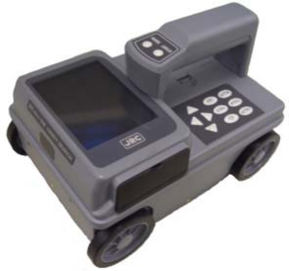
<Appearance of the NJJ-95B>
vii
Table of Contents
Preface i
Before Operation ii
<Precautions for Use> v
<Appearance of the NJJ-95B> vii
Glossary of Terms xi
1 Description of Equipment 1
1.1 Function 1
1.2 Features 3
1.3 Configuration 6
1.4 Overall System Diagram 7
1.5 Configuration 8
2 Parts Names and Functions 10
2.1 Handy Search NJJ-95B 10
2.2 Example of Scan Test Screen 14
2.2.1 Scan test screen example (during testing) 14
2.2.2 Scan test screen example (not during testing) 16
2.3 Parameter Settings Screen 19
2.3.1 Display color 19
2.3.2 Inversion of the screen 20
2.3.3 Display mode 21
2.3.4 Gradation system 22
2.3.5 Calibration method 22
2.3.6 Depth calibration 23
2.3.7 Date, time 23
2.3.8 Data No. 24
2.3.9 Distance compensation 24
2.3.10 Output Data Format 25
2.3.11 Display Range 25
2.3.12 Character Mode 25
2.3.13 Return to standard 26
2.4 CF Control screen 27
3 Operating Method 28
3.1 Scanning Test Preparation 30
3.2 Scan Test 36
3.2.1 Power-on Procedure 36
3.2.2 Scan Test 36
3.2.3 Sensitivity 38
3.2.4 Antenna Mark 38
viii
3.2.5 Real time manual deduction processing 40
3.3 Operation while not Scan Testing 42
3.3.1 Mode switching 42
3.3.2 Sensitivity switching 43
3.3.3 Cursor operation 43
3.4 Image Processing 45
3.4.1 Manual surface wave processing 45
3.4.2 Peak Processing 47
3.4.3 Reproduction of original image 49
3.4.4 Fixed surface wave processing 50
3.4.5 Deduction processing 50
3.5 How to Determine Depths and Sample Scan Test Data 52
3.6 External Output Methods 54
3.6.1 Printer Output 54
3.6.2 Data saving in compact flash memory 56
3.7 CF Control Screen 62
3.7.1 Displaying the thumbnail images of saved data 62
3.7.2 Reading saved data 62
3.7.3 Deleting saved data 63
3.7.4 Method for initialization of Compact Flash 65
3.8 Power-off Procedure 67
3.9 Clearing up the radar and accessories 67
3.10 About the Battery Pack and Charger 68
3.10.1 Battery pack BP-3007 series 69
3.10.2 Charging Device BC-3008 series 72
4 Options 74
4.1 Printer DPU-3445 series 75
4.1.1 Printer's main parts names and functions 75
4.1.2 Printer Specification 76
4.1.3 Connecting the battery pack/power source 77
4.2 AC Adapter PW-0904-W1 series 81
4.2.1 AC Adapter Specification 81
4.2.2 Connecting the AC adapter 81
5 Theory 82
5.1 Principle of Operation 82
5.2 Applicable Conditions 83
6 Maintenance Inspection 85
6.1 Daily Inspection 85
ix

Glossary of Terms
A mode
Displays received waveform as it is. The conditions of concrete directly
underneath the Handy Search are displayed as reflected waveform in real
time.
B mode
Displays the vertical cross section of a scan point by gradating the
reflected waveform shown in A mode according to reflection intensity and
continuously displaying it.
BA mode Displays both B-mode and A-mode images at the same time.
Real time
Auto surface wave
processing
Image processing that uses internal fixed surface wave data to
automatically remove the wave reflected from the surface of the concrete
during scanning and only shows the reflected wave from rebar etc.
Real time
Manual
Deduction
processing
Image processing used in the case that the effect of the reflected waves
from the surface of the concrete can not be fully removed using the
internal fixed surface wave data of the real time auto surface wave
processing. Thus, reflected waves in the form of stripes remain in the
scanning results.
Image processing where an arbitrary line is designated while scanning.
The data of the designated line is subtracted from the scanning results
data, and the reflected wave from the concrete surface is automatically
removed. Thus, only the reflected waves from rebar etc. are shown.
Manual
Surface wave
processing
Image processing where an arbitrary line is designated from scanning
results. The surface portion of the data from the designated line is
subtracted from the scanning results data, and the reflected wave from
the concrete surface is automatically removed. Thus, only the reflected
waves from rebar etc. are shown.
Peak processing
Image processing that shows only the waveform of the first peak on the
+side of the scanning results.
This enables removal of multiple reflected signals and only displays the
upper rebar.
Fixed surface
wave processing
Image processing that uses internal fixed surface wave data to remove
the wave reflected from the surface of the concrete and only shows the
reflected wave from rebar etc.
Deduction
processing
Image processing where an arbitrary line from the scanning results is
designated and the designated line is subtracted from the scanning
results data. Stripe reflected waves throughout the entire depth, such as
reflected waves from the concrete surface and reflected waves from the
rear surface etc., are removed and only the reflected waves from rebar
etc. are shown.
Reproduction of
original image
This processing restores the image processing result to the original state
and displays unprocessed raw data.
Distance feed
system
Method that performs scanning in accordance with Handy Search's
traveling distance, using the distance detector mounted on the wheels of
the Handy Search.
Time feed system Method that performs B-mode scanning at preset time intervals,
regardless of movement of the Handy Search.
Relative dielectric
constant
Object-specific coefficient. The radio wave propagation rate changes with
the value of the relative permittivity. Therefore, the wave propagation
velocity and scanning depth change change based on the relative
permittivity of the concrete. Calculation error of scanning depth can be
reduced by setting a depth calibration value.
xi

1 Description of Equipment
This equipment is indispensable for repairing/rebuilding and maintaining reinforced
concrete structures using its accurate and speedy diagnostic technology.
The Handy Search concrete internal probe vehicle, NJJ-95B, (hereafter called this
radar) radiates electromagnetic waves through the surface of concrete and receives
reflected signals from objects found inside such as reinforcing steel bars, cavities, or
other objects that have different electrical characteristics from concrete. Object
position and depth are then displayed and recorded as image data.
CAUTION
Making a judgement on the search results considering the depth sensing
capability of the NJJ-95B:
Since the depth sensing capability of the radar is subject to the conditions of
the object of investigation, judging the search results with no consideration of
the depth sensing capability may cause the accidental cutting of rebar.
1.1 Function
This radar has the following functions:
• Sense depth :5 – 300 mm*1
• Display mode: :B mode (vertical cross section)
BA mode (vertical cross section and reflected waveform
display)
• Image processing during sensing :Automatic real-time surface wave
processing
Real time manual deduction processing
• Sensing method :Distance feed system (sensing method based on the
distance the main body moves)
Time feed system (sensing at preset time intervals)
• Sense deptch :Max 15 m (case of using time feed – 150 seconds)
• Internal memory :Max 15 m (case of using time feed – 150 seconds)
Image processing: :Manual surface wave processing, fixed surface wave
processing, peak processing, deduction processing, and reproduction of original
image
• External output*2 :Printer output (IrDA)
• Saving data :Compact flash memory card
- 1 -
*1: For the case that the relative dielectric constant of concrete is a uniform 6.2
and the upper rebar has a diameter of 6 mm or more
*2: The printer is optional.
- 2 -
1.2 Features
This device has the following features:
(1) The material of the object to be scanned can be either metallic or non-metallic
Reflected electromagnetic waves are generated at an interface when the
electrical property of an object is different from that of concrete. Thus, this radar
can probe polyvinyl-chloride pipes and cavities (dependent on the position and
size) as well as the reinforcing steel bars. Note that polyvinyl-chloride pipes and
cavities echo weakly in compared with the reinforcing steel bars.
If a polyvinyl-chloride pipe or cavity is near or below the reinforcing steel bars,
the reflected signals from the polyvinyl-chloride pipe or cavity may not be
obtained due to the strong reflected signals from the reinforcing steel bars. Thus,
care should be taken when you make a judgment on the search results.
(2) Detects rebars that cross the scanning direction
Rebar that cross the scanning direction transmit a large magnetic wave
reflection. On the other hand, rebar that is parallel to the scanning direction
transmit a smaller magnetic wave reflection. Even if scanning is performed
above rebar that is parallel to the scanning direction, this device can still detect
any rebar that is crosswise to the scanning direction.
(3) Obtaining continuous scanning results
The scanning results are obtained as a representation of the vertical cross
section of the inside of concrete. Thus, a comprehensive view of the internal
concrete conditions can be obtained.
(4) Obtaining scanning results at the site
Handy Search does not need to be secured to the surface of concrete.
Scanning is carried out while Handy Search is moved and results concerning
the internal conditions of the concrete can be provided immediately.
(5) Saving and reading scan data
Using a compact flash memory, scan data can be saved and reopened
(maximum of roughly 50 sets of data can be saved in text format for a depth of
15 m using a 512 MB compact flash). The data can also be loaded from the
compact flash memory card into a PC by using a card reader or the like.
(6) Printing without cable connection
The unit is equipped with IrDA, therefore, printing can be performed without
using a cable using a DPU-3345 series printer.
- 3 -
However, the IrDA optical receptors for this unit and the printer must be set
facing each other at a distance of 50 ~ 500 mm (without any obstacles between
them).
(7) Performing real time automatic surface wave processing
Internal fixed surface wave data is used to automatically remove the wave
reflected from the surface of the concrete during scanning enabling the showing
of the reflected wave from rebar.
Furthermore, surface wave processing can be switched to processing that
uses scan data surface waves during scanning (real time manual deduction)
enabling highly accurate surface processing.
(8) Displaying the data of an arbitrary point after scanning (scroll function)
This radar can store 15m woth of data at a time and display the data of
arbitrary points continuously.
(9) Changing sensitivity and performing image processing for scan data
This radar can display scan results after changing sensitivity or performing
image processing (manual surface wave processing, peak processing,
reproduction of original image, fixed surface wave processing, or deduction
processing). Thus, performing a scan test again with a new sensitivity setting is
not necessary.
(10) A mark can be displayed in the scan results using the cursor mark function.
A maximum of 7 cursor marks can be placed in the scan results to display the
scan position and depth of the mark.
(11) Providing the screen inversion function
(11) Screen inversion function is available
In case of scanning from right to left on a wall surface, the display on the
screen is upright (normal). In the case of scanning left to right, the display will
be inverted.
Therefore, the user can achieve the correct display by performing the scan
either right to left or left to right.
(12) Recording of date and settings
The main unit records the date and settings (data number, sensitivity, etc.)
using a backup function. When data is output, the date and settings are
recorded.
- 4 -
(13) Compact and light weight
This radar weighs only about 1.1 kg, so it is easy to operate.
(14) Operating with the battery pack and commercial power supply
This radar can operate with the battery pack for about 1.5 hours (at normal
temperature). It can also operate with the commercial power supply when an AC
adapter (optional) is used.
- 5 -

1.3 Configuration
Standard components
Table 1-1 shows the standard configuration of the Handy Search NJJ-95B
Table 1-1 Standard Components
Name Model Number Quan
tity
Remarks
Handy Search NJJ-95B 1
Battery pack BP-3007 series 1
Battery charger BC-3008 series 1
AC cable CB-A01-J1-E series 1 For the battery
charger
Hand strap H-7ZYMD0018 1
Compact flash memory card CF115-512M 1 Memory size: 512MB
Storage box H-7ZYMD0017 1
Instruction manual DC00-NJJ-95B 1
Quick instruction sheet DC10-NJJ-95B 1
License agreement for software DC20-NJJ-95B 1
Users Guide CD-R H-7ZYMD0016 1
Options
Table 1-2 shows optional products that are provided in addition to the
standard components.
Table 1-2 Options
Name Model Number Remarks
Printer set CMZ-203
Set configuration: Printer (DPU-3445 series)
Paper holder (RH-48-00 series)
Battery pack (BP-3007 series)
Recording paper (TP451C)
AC adapter set CBD-2485 Set configuration: AC adapter (PW-0904-W1 series)
AC cable (CB-A01-J1-E) series
Battery charger set CBK-154 Set configuration: Adapter (BC-3008 series)
AC cable (CB-A01-J1-E series)
Battery pack BP-3007 series Shared between handy search and printer
Printing paper TP451C Set of 10 rolls
- 6 -
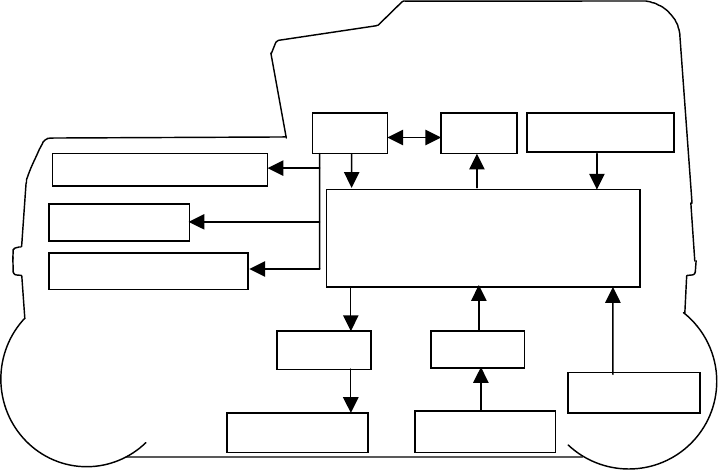
1.4 Overall System Diagram
Table 1-1 shows the total configuration of the Handy Search NJJ-95B
Trans Rec. antenna
ReceiveTrans
Com
p
act Flas
h
IrDA Trans
Control section
Op ke
y
Distance Detector
Memo
CPU
LCD
Figure 1-1 Overall System Diagram
- 7 -
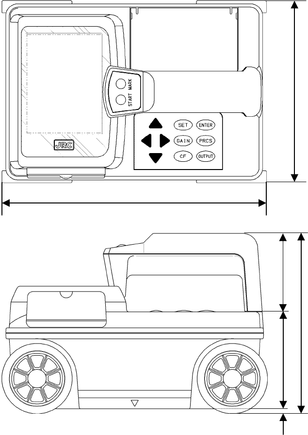
1.5 Configuration
Figure 1-2 shows the external views of this radar.
Plan view drawing
149
216
Side view drawing
147
79 64 4
Fig. 1-2. Handy Search NJJ-95B external dimensions diagram
- 8 -
Rear view
[Units in trigonometry: mm]
- 9 -
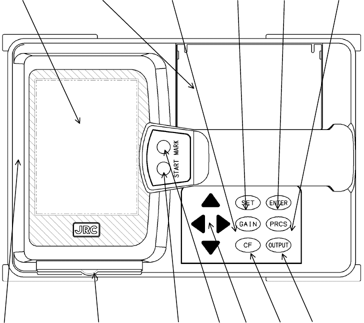
2 Parts Names and Functions
2.1 Handy Search NJJ-95B
This section shows the operation panel of this unit and explains the functions for each group.
1 2 3 4 5 6
7 8 9 10 11 12 13
Figure 2-1 Top View
- 10 -
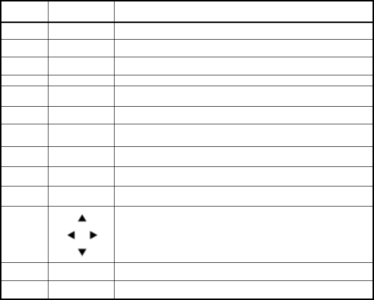
Table 2-1 Main Functions of Parts on the Handy Search
Number in
Square Label Function
1 (None) Liquid crystal display
2 (None) Battery holder
3 GAIN Sets the sensitivity
4 SET Sets each of the parameters.
5 ENTER Decision key for start of image processing and various types of
selection.
6 PRCS Switch to image processing mode.
7 (None) IrDA optical receptor for communicating with the printer
8 (None) Compact flash memory card slot
9 START Starts/stops scan tests.
10 MARK Displays a mark on the scan test screen.
11
Used for movement of cursor and screen and making changes to the
various parameters.
12 CF Switch to the CF control screen.
13 OUTPUT Key for outputting data.
- 11 -
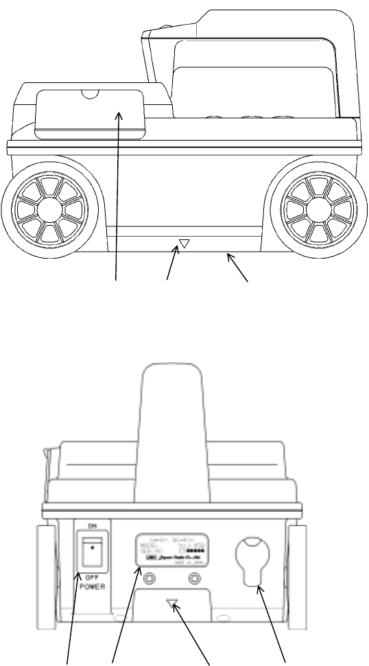
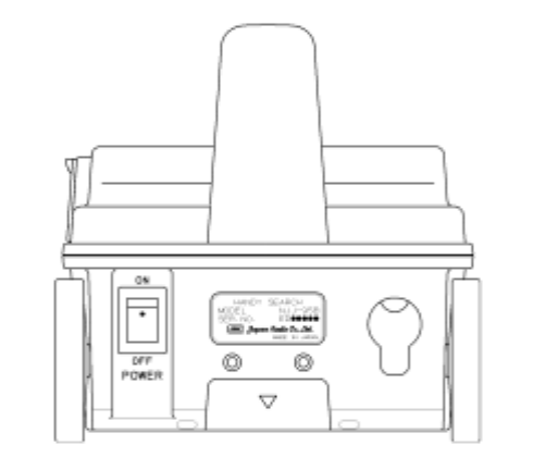
8 14 15
Figure 2-2 Side View
16 17 14 18
Figure 2-3 Rear View
- 12 -

Table 2-2 Functions of Parts on the Side and Rear Panel
Number in
Square Label Function
14 ▼ Mark indicating the scan test position.
15 (None) Antenna face to radiate and receive electromagnetic waves
16 POWER ON OFF Turns power on and off.
17 (None) Equipment nameplate
18 (None) Connector for AC adapter
- 13 -
2.2 Example of the Scan Test Screen
Describe the configuration for each of the scan test screens.
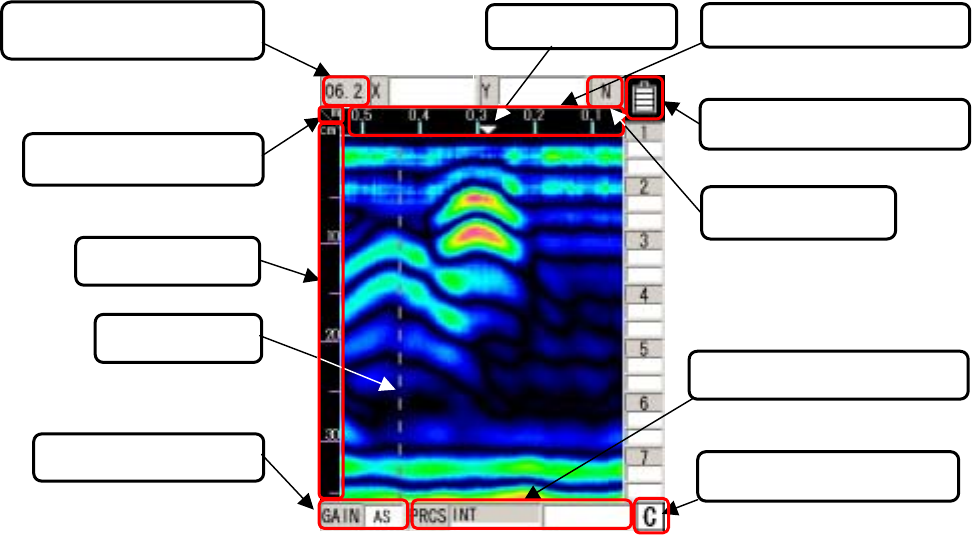
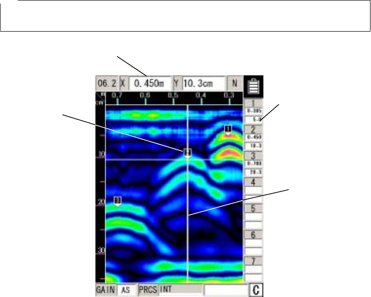
2.2.1 Scan test screen example (during testing)
An example of a scan test screen (during scanning) is shown in Fig. 2-4.
(2)Calibration method
(6)Antenna Mark (7)Distance moved gauge
(1)Depth calibration value
(3)Depth gauge
(4)Fixed cursor
(8)Battery capacity display
(10)Image processing display
(11)External output display
(9)Display range
(5)Sensitivity display
Fig. 2-4 Scanning test screen example (during scanning)
(1) Depth calibration value
Displays the depth calibration value set at the parameter settings screen.
The method for setting the depth calibration value can be found in 2.3.6 Depth
Calibration.
(2) Calibration method
Displays the calibration method set using the parameter settings screen.
Distance feed system displays “m” and time feed system displays “s”.
The method for setting the calibration method can be found in section 2.3.5 of this manual
under “Calibration Method”.
- 14 -
(3) Depth gauge
Displays a scanning depth gauge.
The scanning depth gauge changes based on the depth calibration value.
(4) Fixed cursor
The fixed cursor is the cursor that is used to designate surface waves used for real time
manual deduction processing.
See section 3.2.5 “Real Time Manual Deduction processing” for the method used for real
time manual deduction processing.
(5) Sensitivity display
Shows the scanning sensitivity setting.
See section 3.2.3 “Sensitivity for the method used to switch sensitivity”.
(6) Antenna mark
Antenna mark that shows a mark for the scan distance.
See section 3.2.4 “Antenna Mark” for how to use the antenna mark.
(7) Distance moved gauge
Gauge for the distance moved while performing a scanning test.
(8) Battery capacity display
Shows the general amount of capacity remaining in the battery pack that is being used.
(9) Display range
Shows the display range set using the parameter settings screen.
See section 2.3.11 “Display Range” for the method used to set the display range.
(10) Image processing display
Displays the image processed items for processing performed on the sense test results.
See section 3.4 “Image Processing” for how to process images.
(11) External output display
Shows the external output data destination set using the parameter settings screen.
See section 2.3.10 “External Output” for how to set up external output.
- 15 -
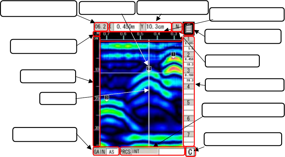
2.2.2 Scan test screen example (not during testing)
An example of a scan test screen (not during scanning) is shown in Fig. 2-5
Fig. 2-5 Sensing test screen example (not during sensing)
(6)Antenna Mark
(11)Cursor mark coordinates
(10)Dis
p
la
y
ran
g
e
(13)External out
p
ut dis
p
la
y
(12)Image processing display
(9)Battery capacity display
(5) Sensitivity display
(
4
)
Curso
r
(3) De
p
th
g
au
g
e
(1)Depth calibration value (8) Distance moved gauge
(7)Cursor Coordinates
(2)Calibration method
(1) Depth calibration value
Displays the depth calibration value set at the parameter settings screen.
The method for setting the depth calibration value can be found in section 2.3.6 “Depth
Calibration”.
(2) Calibration method
Displays the calibration method set using the parameter settings screen.
Distance feed system displays “m” and time feed system displays “s”.
The method for setting the calibration method can be found in section 2.3.5 “Calibration
Method”.
(3) Depth gauge
Displays a scanning depth gauge.
The scanning depth gauge changes based on the depth calibration value.
- 16 -
(4) Cursor
Indicates a cursor mark on the scanning test screen and is a “criss-cross” cursor that is
used to designate A mode waveform display points in B mode and for scrolling the
sensing test screen.
(5) Sensitivity display
Shows the scanning sensitivity setting.
See section 3.3.2 “Switching Sensitivity” for the method used to switch sensitivity.
(6) Cursor mark
A mark that shows an arbitrary point on the scanning test screen.
See section 3.3.3 “Cursor Operation” for how to display, erase the cursor mark.
(7) Cursor Coordinates
Shows the coordinates of the cross point of the cursor in item (4).
The distance moved is shown in “X” and depth in “Y”.
(8) Distance gauge
Distance gauge in the direction the scanning was performed.
Displays the distance the main unit has moved.
(9) Battery capacity display
Shows the general amount of capacity remaining in the battery pack that is being used.
(10) Display range
Shows the display range set using the parameter settings screen.
See section 2.3.11 “Display Range” for the method used to set the display range.
(11) Cursor mark coordinates
Displays the coordinates of the cursor mark in item (6).
Below each of the mark numbers, the movement distance (X) is shown in the first row
and the depth (Y) is shown in the second row.
(12) Image processing display
Displays the image processed items for processing performed on the test results.
See section 3.4 “Image Processing” for how to process images.
- 17 -
(13) Output data display
Shows the output data destination set using the parameter settings screen.
See section 2.3.10 “External Output” for how to set up external output.
- 18 -
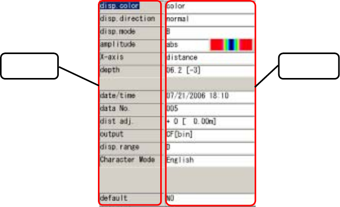
2.3 Parameter Settings Screen
While scanning is stopped, pressing of the 4 SET key enables switching the screen to the
parameter settings screen (see Fig. 2-6) and each of the settings can be changed. To return to the
scanning test screen, press the 4 SET key again.
Selections Settings
[Left column] [Right column]
Display color Color
Screen inversion Normal
Display Mode B
Level adjustment method Absolute value
Measurement method Distance feed
Depth calibration 06.2 [-3]
Date 2006/07/21 18:09
Data No. 005
Distance correction +0 [0.00 m]
External output CF [binary]
Display range Depth
Character mode Japanese
Return to standard No
Figure 2-6 Parameter Setting Screen
2.3.1 Display color
"Color" or "Monochrome" can be selected for the display color for the liquid crystal display of the
- 19 -
main unit.
In order to change the display color, select “display color” from the settings using the ▲▼ cursor
keys (inverting display) and switch to item selection using the cursor keys.
Select “color” or “monochrome” using the ▲▼ cursor keys or use the cursor keys to switch
to item selection.
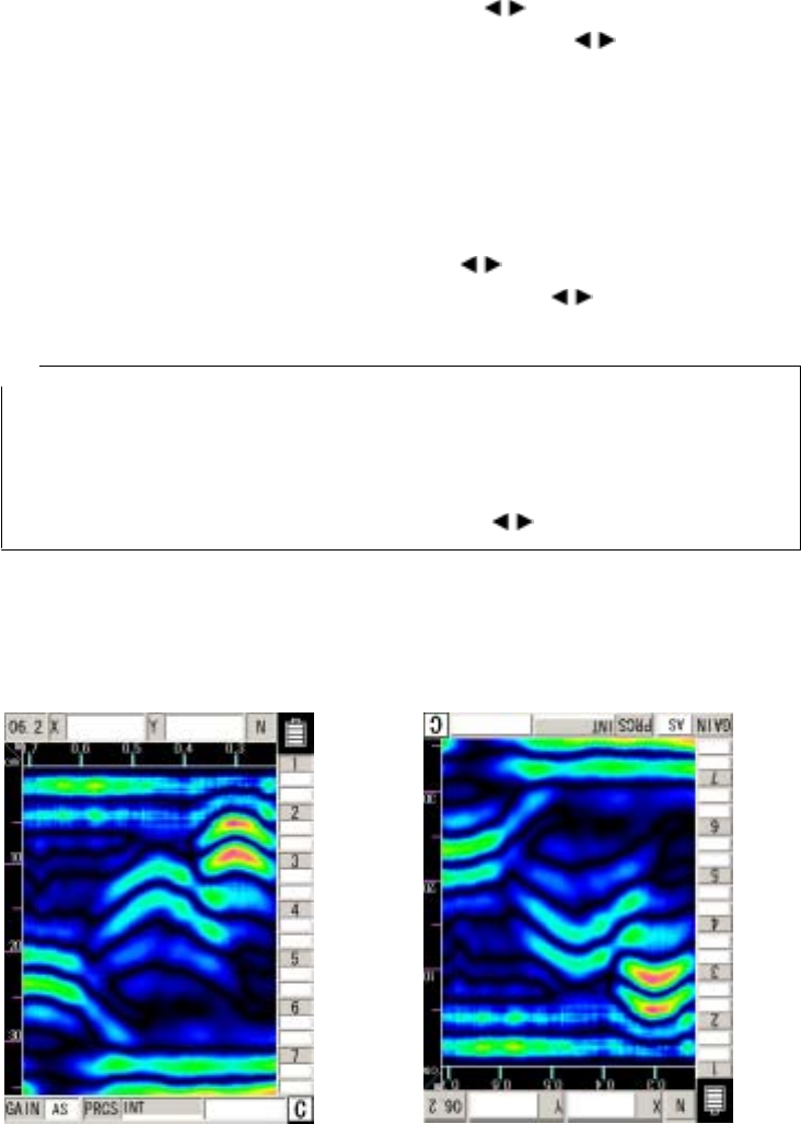
2.3.2 Inversion of the screen
This unit supports screen display inversion while it moves (scans) to the right and to the left,
thereby displaying the scanning test screen upside down. (See Figure 2-7.)
In order to invert the screen, select “Invert Screen” from the set up items using the ▲▼ cursor
keys (invert display) and switch to item selection using the cursor keys.
Select “normal” or “inverted” using the ▲▼ cursor keys or use the cursor keys to switch to
item selection.
Remarks
The direction of image data output by the printer (optional) is changed depending on the setting
of the screen inversion function.
For the printer to always output image data in the same direction, retain the same setting
"Normal or Reverse" for "Inversion of the screen."
• While the screen display is inverted, the cursor keys ▲▼ move in the opposite direction.
(They function in the same direction as when "Normal" is selected for "Inversion of the
screen.")
Screen display direction [Normal] Screen display direction [Reverse]
- 20 -

Figure 2-7 Screen Inversion Function
2.3.3 Display mode
This unit can scan/display data in both "B” mode (vertical cross section) and "BA” mode (vertical
cross section and reflected waveform display).
In order to change the display mode, select “display mode” from the settings using the ▲▼ cursor
keys (inverting display) and switch to item selection using the cursor key.
Select “B” or “BA” using the ▲▼ cursor keys or use the cursor keys to switch to item
selection.
Remarks
• When the display mode is switched between "B" and "BA" after scanning, data scanned in "B
mode" is displayed in "BA mode," and data scanned in "BA mode” is displayed in "B mode." See
section 3.3.1 “Mode switching."
- 21 -
2.3.4 Gradation system
"Absolute value" or "Offset" can be selected for the gradation system.
When "Color" is selected for "Display color," the absolute value gradation changes between Black
→ Indigo → Green → Yellow → Red as the A-mode amplitude increases as shown in Figure 2-8.
The offset gradation changes between Black → Indigo → Green → Yellow → Red from the left in A
mode as shown in Figure 2-9.
When "Monochrome" is selected for "Display color," the gradation changes between
White → Gray → Black in this order.
In order to change the gradation method, select “Gradation Method” from the set up items using
the ▲▼ cursor keys (invert display) and switch to item selection using the cursor keys.
Select “absolute value” or “offset” using the ▲▼ cursor keys or use the cursor keys to
switch to item selection.
Figure 2-8 Absolute Value Gradation Figure 2-9 Offset Gradation
2.3.5 Calibration method
"Distance feed" or "Time feed" can be selected as the scanning method of this unit.
When "Distance feed" is selected, the scanning method measures/displays data in units of 5 mm
in "B/BA mode" conforming to the wheels' moving distance. When "Time feed" is selected, the
scanning method measures/displays data at 50 ms intervals in "B/BA mode," regardless of the
wheels' moving distance.
In order to change the scanning method, select “Scanning Method” from the set up items using
the ▲▼ cursor keys (invert display) and switch to item selection using the cursor keys.
Select “distance feed” or “time feed” using the ▲▼ cursor keys or use the cursor keys to
switch to item selection.
- 22 -
2.3.6 Depth calibration
The depth calibration is the scan depth obtained from the wave propagation speed and reflected
time with the depth gauge corrected using the relative dielectric constant of concrete. The value
must be changed based on the condition (such as moisture content) of the concrete being scanned.
A large difference between the relative permittivity of the concrete being scanned and the depth
calibration value will cause a large depth error.
In order to reduce the depth error, detect an object where the depth can be confirmed (as with
rebar) and peform a correction of the depth guage by setting the depth calibration value so that the
depth displayed in the scanning results basically matches the actual depth.
If it is not possible to scan an object (such as the case with rebar) where the depth can be
confirmed, and the depth calibration value is unclear, it is recommended to set the depth calibration
to “08.0 (+0)”.
In order to change the depth calibration value, select “Depth Calibration” from the set up items
using the ▲▼ cursor keys (invert display) and switch to item selection using the cursor keys.
Set the “depth calibration value” using the ▲▼ cursor keys and use the cursor keys to
switch to item selection.
Remarks
● The intervals on the depth gauge are not equivalent. Confirm the depth using the cursor
display value.
2.3.7 Date, time
This radar contains a rechargeable button-type lithium battery with which dates and times can be
recorded.
In order to correct time and/or date, select “Date and Time” from the set up items using the ▲▼
cursor keys (invert display) and switch to item selection using the cursor keys.
Select the position of the date or time that you would like to correct using the cursor keys
and change the values using the ▲▼ keys.
Switch to item selection using the keys.
- 23 -
2.3.8 Data No.
Data is recorded and numbered when externally output. The data number (Data No.) is
incremented each time data is recorded.
In order to change the data No., select “Data No.” from the set up items using the ▲▼ cursor
keys (invert display) and switch to item selection using the cursor keys.
Select the position that you would like to correct using the cursor keys and change the
values using the ▲▼ keys.
Switch to item selection using the keys.
Remarks
When data is to be recorded again, it can be easily managed by changing the value of Data No.
2.3.9 Distance compensation
This unit determines distance using the number of rotations the wheels make. Thus, wear of the
wheels causes an error in calculating the scanning distance. If the scanning distance has an error,
compensate the distance error.
In order to change the distance error correction value, select “Distance Correction” from the set up
items using the ▲▼ cursor keys (invert display) and switch to item selection using the cursor
keys.
Set the “distance error correction value” using the ▲▼ cursor keys and use the cursor keys
to switch to item selection.
(Example of distance error compensation)
a) Perform a 1m (actual value) scan test and stop the scanning.
b) Press the 4 SET key and switch to the parameter settings screen
c) Select the settings item “Distance Correction” using the ▲▼ cursor keys (invert display) and
switch to item selection using the cursor keys.
d) d) Using the ▲▼ cursor keys, set the correction value so that the distance of the last line
(displayed by [ ] to the right of the correction value) is as close as possible to 1 m.
e) Use the cursor keys to switch to item selection and press the 4 SET key to return to the
scan test screen.
Remarks
● The distance of the last scan test line is displayed to the right of the compensation value.
When the compensation value is changed, the distance is also changed in accordance with
the new compensation value.
With this value as a rough standard, set a new compensation value.
- 24 -
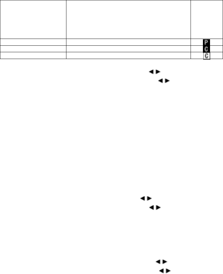
2.3.10 Output Data Format
Set the external output destination of scan test data. The table below shows the relationship
between external output destinations and output data formats.
The currently set external output destination is indicated with the character displayed at the lower
right of the scan test screen.
External Output
Destination Output Data Format
Scan Test
Screen
Destination
on
Measurem
ent Screen
Printer (I) Print to the printer
CF [text] Saved in text format in compact flash memory
CF [binary] Saved in binary format in compact flash memory
In order to change external output, select “External Output” from the set up items using the ▲▼
cursor keys (invert display) and switch to item selection using the cursor keys.
Set the “external output” using the ▲▼ cursor keys and use the cursor keys to switch to
item selection.
See Section 3.6 External Output Methods for the operation method.
2.3.11 Display Range
The display range is an item for setting the display limits of the scanning depth. There
are three settings: “deep”, “standard”, and “shallow”.
Set the range of display based on depth of the object to be scanned using the following.
Depth of the object to be scanned is 30 cm or less: “deep”
The depth of the object to be scanned is 20cm or less: “standard” (same as
NJJ-95A)
Depth of the object to be scanned is 10cm or less: “shallow”
In order to change the display range, select “display range” from the settings using the ▲▼ cursor
keys (inverting display) and switch to item selection using the cursor key.
Set the “display range” using the ▲▼ cursor keys and use the cursor keys to switch to item
selection.
2.3.12 Character Mode
Switches displayed characters between Japanese and English.
In order to change the character mode, select “Character Mode” from the settings using the ▲▼
cursor keys (inverting display) and switch to item selection using the cursor key.
Set the type of characters using the ▲▼ cursor keys and use the cursor keys to switch to
item selection.
- 25 -

2.3.13 Return to standard
This function changes all the parameters other than "Data, time" back to the standard settings.
In order to revert to standard settings, select “Return to Standard” from the set up items using the
▲▼ cursor keys (invert display) and switch to item selection using the cursor keys.
Select “Yes” using the ▲▼ cursor keys and use the cursor keys to switch to item selection.
- 26 -
2.4 CF Control screen
While scanning is in off status and the 12 CF key is pressed, the screen switches to the CF control
screen and compact flash memory control can be performed. Return to the scan test screen by
pressing on the 12 CF key once more or “Cancel”.
See 3.6.2 ~ 3.7.4 for how to control the compact flash memory.
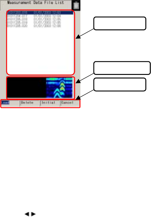
The CF control screen is shown in Fig. 2-10.
(3) Control items
(2) Thumbnails
(1)File selection
Figure 2-10 CF Control Screen
(1) File Selection
The filenames for data saved on the compact flash memory are displayed.
Select the file (inverted display) using the ▲▼ cursor keys.
(2) Thumbnail image display
Displays the file selected in (1) as a thumbnail.
(3) Control items
Control items for the compact flash memory.
Select (inverted display) an item using the cursor keys and choose it with the 5 ENTER key.
- 27 -
3 Operating Method
The numbers in squares in this chapter correspond to the numbers in Tables 2-1 and 2-2 on pages 8-11.
Furthermore, keys are displayed on this unit using bold Gothic characters.
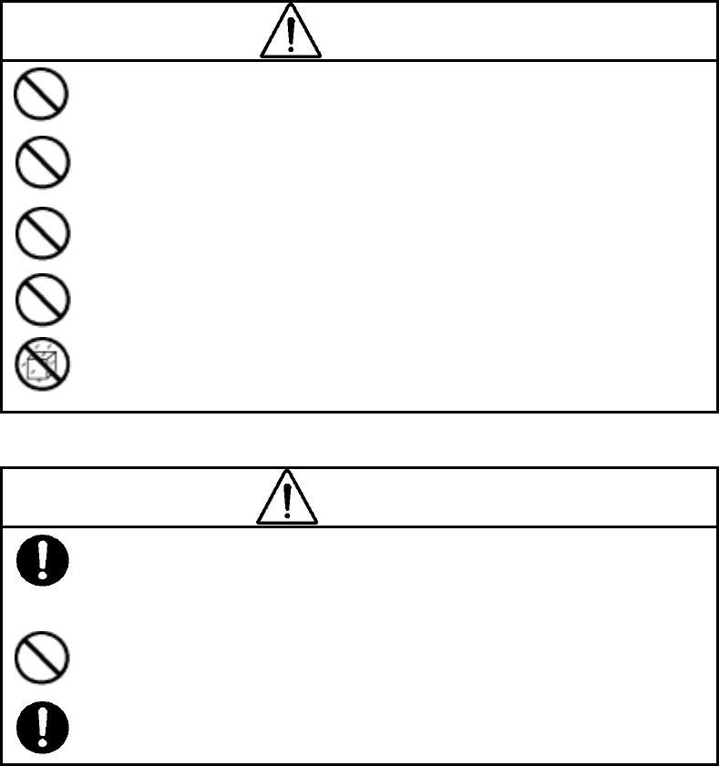
WARNING
Do not use any battery pack other than the BP-3007-A1 or any AC adapter
other than the PW-3009-W.。
Doing so could cause fire, electric shock, or breakdown.
Do not short-circuit the terminals of the battery charger or battery pack.
Doing so could cause fire, explosion, or breakdown.
Do not insert anything metallic or flammable into the compact flash memory
card slot. Doing so could cause a personal injury, fire, electric shock, or
breakdown.
Do not use any charger other than the dedicated battery charger to charge
the battery pack.
Doing so could cause fire, electric shock, or breakdown.
Handy Search has a waterproof construction but must not be placed in water.
Do not expose the NJJ-95B to water or moisture, and do not use it in rainy weather. Doing so
could cause an electric shock or breakdown.
CAUTION
Making a judgment on the scan results considering the depth scanning capability of the
NJJ-95B.
Since the depth scanning capability of the radar is subject to the conditions of the object of
investigation, judging the scan results with no consideration of the depth scanning capability
may cause the cutting of rebar.
Put your hand through the hand strap and hold the NJJ-95B.
Dropping of the radar may cause an accident such as a device breakdown or personal injury.
Do not use any battery pack other than the BP-3007-A1 or any AC adapter other than the
PW-3009-W.
Doing so may cause fire, electric shock, or breakdown.
- 28 -
CAUTION
Point the antenna surface in the direction of the probed object (concrete) while you are
performing a probe.。
If it is pointed into the air or otherwise unsuitable direction, it can cause malfunction of other
equipment or other such accidents.
Do not use the NJJ-95B in the vicinity of a radio or TV set.
Doing so may cause noise or poor reception such as disturbance of television pictures. Doing
so also adversely affects the depth sensing capability of the radar, and may cause the cutting
of reinforcing steel bars.
Do not use the NJJ-95B near a cell phone or transceiver that transmits electromagnetic
waves. Electromagnetic waves from the cell phone or transceiver adversely affect the depth
sensing capability of the radar, and may cause the cutting of reinforcing steel bars.
When the NJJ-95B is used for scanning on the road, take safety precautions such as
providing guard fences to prevent traffic accidents.
”
- 29 -
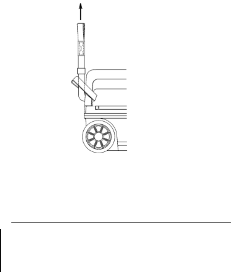
3.1 Scanning Preparation
(1) Mounting the hand strap
A hand strap for drop prevention is provided as standard with this radar. Mount the hand strap on
the handle of the radar as shown in Figure 3-1, put your hand through the hand strap to grip the
handle, and start sense testing.
Figure 3-1 Hand Strap
(2) Connecting the power source (battery pack)
This radar can be operated with the battery pack or 100 VAC power when an optional AC adapter
is used.
Notes
● Use this radar in a place where the ambient temperature is 0 to 50 °C and the humidity is
45 to 80%.
● Do not move the radar in cold condition to a place where it is subject to sharp temperature
rise. Doing so generates condensation inside the radar that could cause a breakdown.
● Confirm that the power switch 16 is set to "OFF" before mounting/dismounting the
battery pack or the AC adapter.
- 30 -
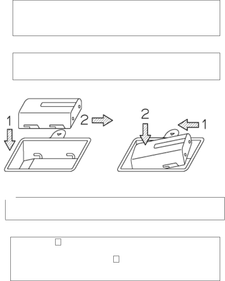
a) Mounting the battery pack (See Figure 3-2.)
1. Confirm that the 16 power switch is set to "OFF."
2. Open the battery cover 2 at the top of this unit, confirm the direction of the battery pack and
put it into the battery holder.
3. Push the battery pack forward to connect with the terminals, and close the battery cover 2.
b) Dismounting the battery pack (See Figure 3-3.)
1. Confirm that the 16 power switch is set to "OFF."
2. Open the battery cover 2 at the top of this radar, and slide the battery pack backward.
3. Push down the rear of the battery pack to raise its front, so it can be easily dismounted.
Figure 3-2 Mounting the battery pack Figure 3-3 Removing the battery pack
Remarks
• When opening the battery cover, hold onto the handle with your left hand, push up on battery
cover lock with your middle finger, open the battery cover slightly and lift the battery cover with
your right hand to easily remove the battery cover.
c) Mounting the AC adapter
1. Confirm that the 16 power switch is set to "OFF."
2. Connect the AC cable to the AC power connector on the AC adapter.
3. Open the AC adapter input connector cover 18 at the rear, and connect the DC jack of the AC
adapter.
4. Connect the AC adapter cable to the socket outlet.
- 31 -
d) Dismounting the AC adapter
1. Confirm that the power switch 16 is set to "OFF," and disconnect the AC adapter cable from
the socket outlet.
2. Pull out the AC adapter DC jack from this unit and close the connector cover for the 18 AC
adapter input.
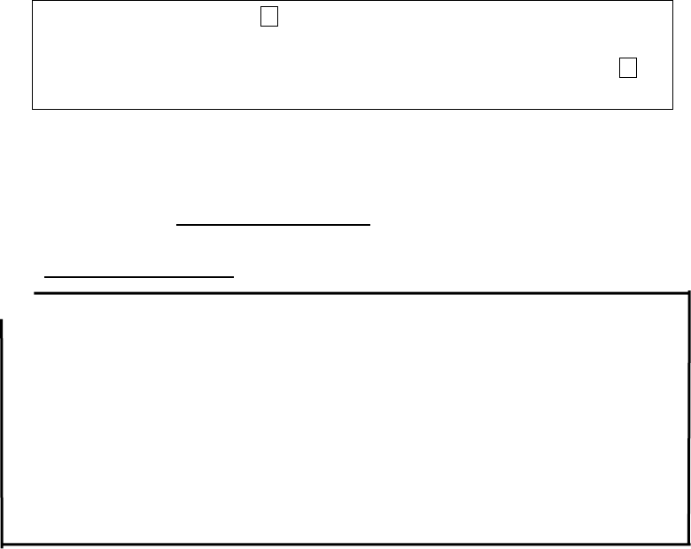
3)Mounting/dismounting a compact flash memory card
This radar can save scan test data by using a compact flash memory card.
To save scan test data, mount the compact flash memory card according the procedure
in Figure 3-4 while the radar power switch is off.
To dismount the compact flash memory card, perform the procedure in Figure 3-5 while
the radar power switch is off.
Notes ● Mount/remove the compact flash memory card while the power switch of this unit
is off.
● Make sure of the insertion direction before mounting the compact flash memory card.
● Operation of this unit has been confirmed with compact flash CF115-512M
manufactured by IO Data. The unit may not operate with a compact flash memory
card of another company, so an IO Data compact flash memory card should be
used.
● Be sure to initialize the compact flash memory using this unit. If this is performed
using other equipment (NJJ-95B, PC etc.) the compact flash may not be recognized.
● Please do not use a compact flash memory that was used with a NJJ-95A. As the
data format used by NJJ-95A and NJJ-95B are different, this may cause an error.
- 32 -
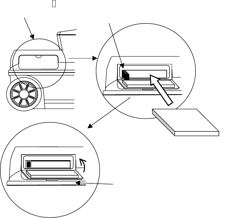
(1) Open the lid over the 8
compact flash insert opening (2) If the eject switch is extended, push in the switch.
Figure 3-4 Mounting the Compact Flash Memory Card
Compact Flash
Memory Card
Com
p
act flash
(3) Insert the compact flash
memory card
(
4
)
Close the lid after insertion
- 33 -
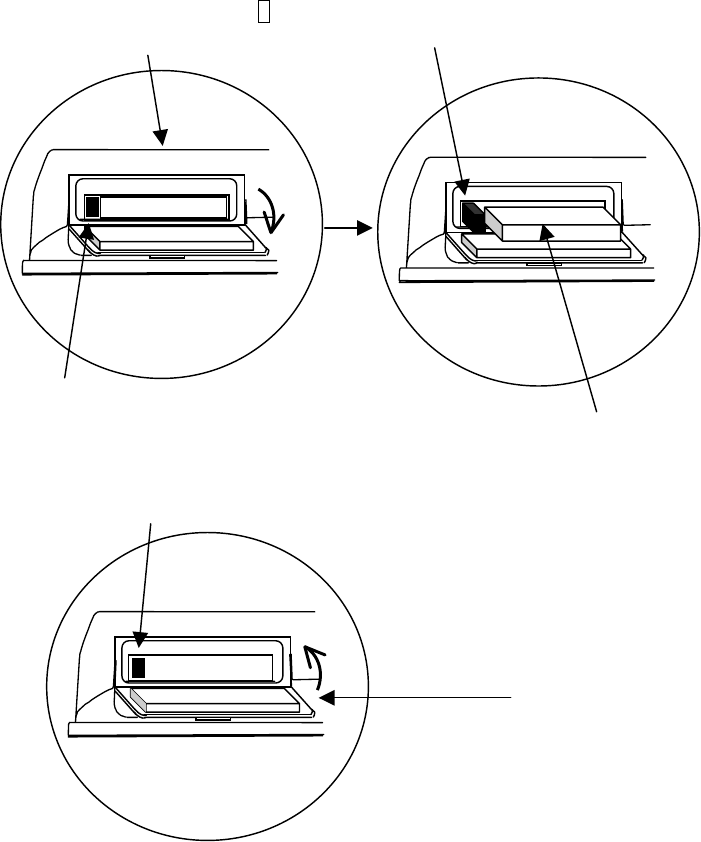
(4) Pull out the compact flash
(3) Press the eject again to enable pulling th
e
com
p
act flash ou
t
Com
p
act flash
(1) Open the lid of the 8
com
p
act flash insert o
p
enin
g
(2) Push the eject so that the ejec
t
button is pushed in
(5) Push the eject button so that the
eject button is pushed in
(6) Close the lid as was to start with
Figure 3-5 Dismounting the Compact Flash Memory Card
- 34 -
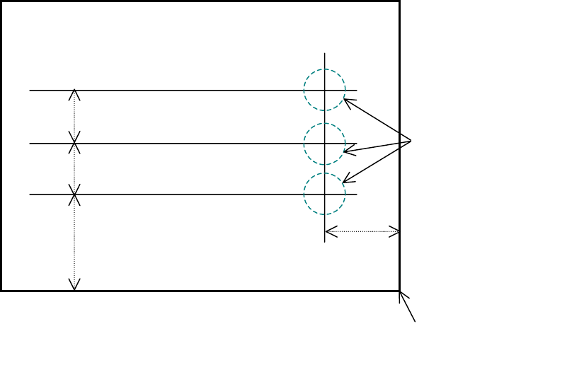
(4) Target Preparation for Scanning
Using chalk (or similar) make markings on the concrete surface to indicate where to start
testing (starting line) and where to scan (scan test line).
Make sure the start line and the scan test line are orthogonal.
(As necessary, in order to perform a retest, use and endpoint of the wall as a standard
for the start line and scan test line)
A scan test applicable set up example is shown in Fig. 3-6.
1m
(Wall Surface)
Object to be sens
e
tested
(
Concrete etc.
)
These should be
orthogonal
2m 1m
Start line
1m
Scan test line 3
Scan test line 2
Scan test line 1
Fig. 3-6 Scan test applicable setup example
Origin
(End of wall, power outlet etc.)
- 35 -
3.2 Scan Test
3.2.1 Power-on Procedure
The 1 liquid crystal display lights up roughly 5 seconds after the power is turned on by turning on
the 16 power switch, and next the initialization screen is displayed. After the initialization screen
completes, the scan test screen is displayed.
After confirming that the scan test screen is displayed on the liquid crystal display, start the scan
test.
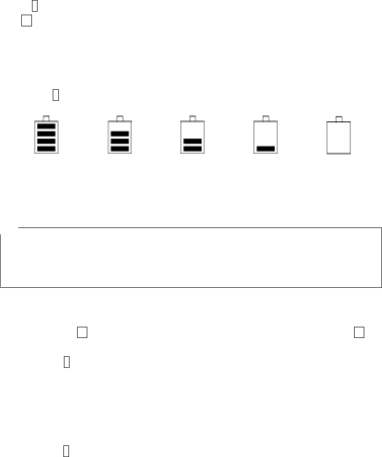
The battery availability indicator is displayed with an approximate value at the upper right of the
LCD screen 1. (See Figure 3-7.)
About 75~100% , About 50~75%, About 25~50%, About 0~25%, About 0%
Figure 3-7 Battery Capacity Indicator
Notes
• This unit gives priority to the AC adapter for power input. Therefore it operates with the AC
adapter when both the battery pack and AC adapter are connected. If the AC adapter is
connected while operating using the battery, the power turns off and then back on.
3.2.2 Scan Test
The scan test method is shown below.
a) Place the 14 V on the side of the unit over the start line and the forward/backward 14 V
over the scan test line.
b) Press 9 START. After about one second, a short single buzzer sound is generated, the
fixed cursor is displayed at a position of about 10cm of the movement distance scale on the
B mode screen, and then scan test preparation is complete.
c) Move the unit on top of the scan test line at a speed of less than 40 cm/s by rotating the
wheels. If speed exceeds 40 cm/s, a buzzer sounds and the data for that timeframe is
invalid. Please perform the scan test again.
d) Press 9 START again to finish. A double buzzer sound is generated and the scan test is
stopped.
However, if the scan distance reaches 15 m, the buzzer sounds twice and the scan test
automatically finishes.
Figure 3-8 shows an example of scan test.
- 36 -
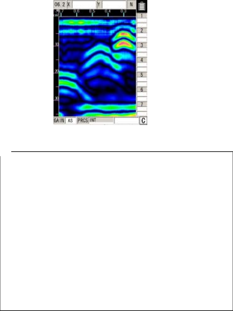
Figure 3-8 B Mode Sense Test
Remarks
• For the settings such as B/BA mode, Distance feed/Time feed, Absolute value gradation/Offset
gradation, Depth calibration value, and Sensitivity, see section 2.3 “Parameter Setting Screen."
• Automatic real-time surface wave processing may not eliminate all waves reflected by the
concrete surface depending on the conditions. If the peak processing of image processing is
performed in this state, waves reflected by reinforcing steel bars may become invisible.
The waves reflected by reinforcing steel bars can be displayed by the method explained in
section 3.2.5 “Manual real-time deduction processing" or section 3.4 “Image
processing."
• If the unit is moved too fast, a buzzer will sound. Data at the time is not displayed.
• Even if this unit moves in the direction opposite to the traveling direction, data will be displayed
on the assumption that the antenna moves in the traveling direction.
• The latest scan test data in B mode includes data about the antenna's center mark "▼" at the
lower part of the case.
• The position of the fixed cursor on the B-mode display indicates the rear end of this radar, and it
can be used to identify the position of the reinforcing steel being scan tested. (See Figure 3-9
for the fixed cursor.)
- 37 -

3.2.3 Sensitivity
When the power is turned on, sensitivity is set to “A shallow”. “A shallow” is a sensitivity setting that
is applicable to the detection of rebar with a depth of less than 10 cm in general concrete.
"A" of "A shallow" indicates the overall sensitivity; "shallow" indicates depth sensitivity.
There are five levels for overall sensitivity: "-2, -1, A, +1, +2." In general, use the unit in the "A"
setting. Use the +side to increase sensitivity and use the –side to reduce sensitivity.
There are two levels for depth sensitivity: "shallow and deep." Select "shallow" when the object to
be probed is at a depth less than 10 cm. Select "deep" when the object to be probed is at a depth of
10 cm or more.
To change the sensitivity, press 3 GAIN . The sensitivity is changed as follows:
A, shallow → +1, shallow → +2, shallow → -2, deep → -1, deep → A, deep → +1, deep →
→ +2, deep → -2, shallow → -1, shallow → A, shallow → +1, shallow →
Remarks
• To change sensitivity for scanning results, press 3 GAIN after scanning.
If sensitivity is changed after scanning, the unit uses the new sensitivity for the next
scanning.
For the changing of sensitivity after scanning, see "Section 3.3.2 Sensitivity Switching."
3.2.4 Antenna Mark
If core-boring or reinforced rebar locations are known beforehand (shown on a
construction diagram) the NJJ-95B can mark the locations by placing an “Antenna Mark”
at the applicable places during scanning.
The method of use for this antenna mark is shown below.
a) Place the 14 V on the side of the unit over the start line and the forward/backward 14 V
over the sense test line.
b) Press 9 START. After about one second, a short single buzzer sound is generated, the
fixed cursor is displayed at a position of about 10cm of the movement distance scale on the
B mode screen, and then scan test preparation is complete.
c) Move the unit on top of the scan test line at a speed of less than 40 cm/s by rotating the
wheels. If speed exceeds 40 cm/s, a buzzer sounds and the data for that timeframe is
invalid. Please perform the scan test again.
d) Push 10 MARK when the 14 V on the side of this unit overlaps the rebar position or
core-boring as based on design blueprints. (A ▼ is shown on the movement distance
gauge)
e) Press 9 START again to finish. A double buzzer sound is generated and the scan test is
- 38 -
stopped.
However, if the scan distance reaches 15m, the buzzer sounds twice and the scan test
automatically finishes.
- 39 -

3.2.5 Real time manual deduction processing
Waves reflected by objects to be probed (e.g., reinforcing steel) at a position near the concrete
surface are difficult to identify because they are combined with waves reflected by the concrete
surface (called surface waves). This radar contains the standard surface wave data (fixed surface
wave data) with which it eliminates the influence of the concrete surface waves in real time, thereby
making it easy to identify the waves reflected by the objects to be probed.
However, with the condition of the concrete surface and moisture content in the concrete and for
special concrete, the effect of the reflected wave from the surface of the concrete may not be fully
removed even if auto surface wave processing for standard surface waves is performed and there
may be lateral stripe reflected waves near the surface.
In this type of situation switch to real time surface wave processing based on surface waves in the
scanning data to remove lateral stripe reflected waves.
Perform manual deduction processing as explained below.
a) Place the 14 V on the side of the unit over the start line and the forward/backward 14 V
over the scan test line.
b) Press 9 START. After about one second, a short single buzzer sound is generated, the
fixed cursor is displayed at a position of about 10cm of the movement distance scale on the
B mode screen, and then scan test preparation is complete.
c) Move the unit on top of the scan test line at a speed of less than 40 cm/s by rotating the
wheels. If speed exceeds 40 cm/s, a buzzer sounds and the data for that timeframe is
invalid. Please perform the scan test again.
d) When results for objects that are not being probed overlap with the fixed cursor position,
push 5 Enter. (See Figure 3-9.)
The reflected wave that the fixed cursor is pointing to can be processed into a surface
wave by real time manual deduction. The resulting data of this processing is indicated in “A”
mode or “BA” mode.
A “↓” is shown at the position that the real time manual deduction processing was
performed on the movement distance guide. In the “Processing” area at the bottom right of
the screen, <<Manual>> is displayed.
e) Press 9 START again to finish. A double buzzer sound is generated and the scan test is
stopped.
However, if the scan distance reaches 15m, the buzzer sounds twice and the scan test
automatically finishes.
- 40 -
Remarks
• Real time manual deduction processing performs the same processing as deduction
processing for image processing during scanning.
See section 3.4.5 “Deduction Processing" regarding deduction processing.
• If image processing is performed for scan data by using real-time manual deduction
processing and the surface wave data for manual surface wave processing is rewritten,
data may not be reproduced during scanning.
See section 3.4 “Image Processing."
• If scanning is to be performed again after scanning is complete using real-time manual
deduction processing, automatic real-time surface wave processing using the fixed
surface wave data will be performed.
• The fixed cursor position shows the rear end of this unit and can be used to decipher the
position of the rebar during scanning.
Example of where results for object that is not being probed
overlaps with the fixed cursor position
(Press 5 ENTER)
Figure 3-9 Display after real-time manual deduction processing
- 41 -
3.3 Operation while not Scanning
3.3.1 Mode switching
This radar can scan test/display data in both "B mode (vertical cross section)" and "BA mode
(vertical cross section and reflected waveform display)". When the display mode is switched
between "B" and "BA" after scanning, data scan tested in "B mode" is displayed in "BA mode," and
data scan tested in "BA mode" is displayed in "B mode." (See Figure 3-10.)
When the “Distance feed system” method is being used as the “Scan test method”, one screen
displays 49 cm of sense test (movement) distance in “B mode” (maximum recordable test distance
is 15 m). In “BA mode” one screen is the same as in A mode, which is 32.5 cm shown in B mode
(maximum recordable scan test distance is 15 m).
The A-mode (waveform display) portion in BA mode indicates the waveform at the vertical cursor
position in BA mode.
Perform the following procedure to switch between the "B mode" and "BA mode:"
a) Push 4 SET while scanning is stopped and switch to the parameter settings screen.
b) Select the settings item “Display Mode” using the ▲▼ cursor keys (invert display) and
transfer to item selection using the cursor keys.
c) Select “B” or “BA” using the ▲▼ cursor keys or use the cursor keys to transfer to
set up items.
d) Push 4 SET to switch to the scan test screen.
Remarks
• If the display mode is switched from “B” mode to “BA” mode or vice versa when the scan
testing stops then the display mode last selected when the scan testing restarts will be in
operation when scan testing is resumed.
B mode BA mode
- 42 -
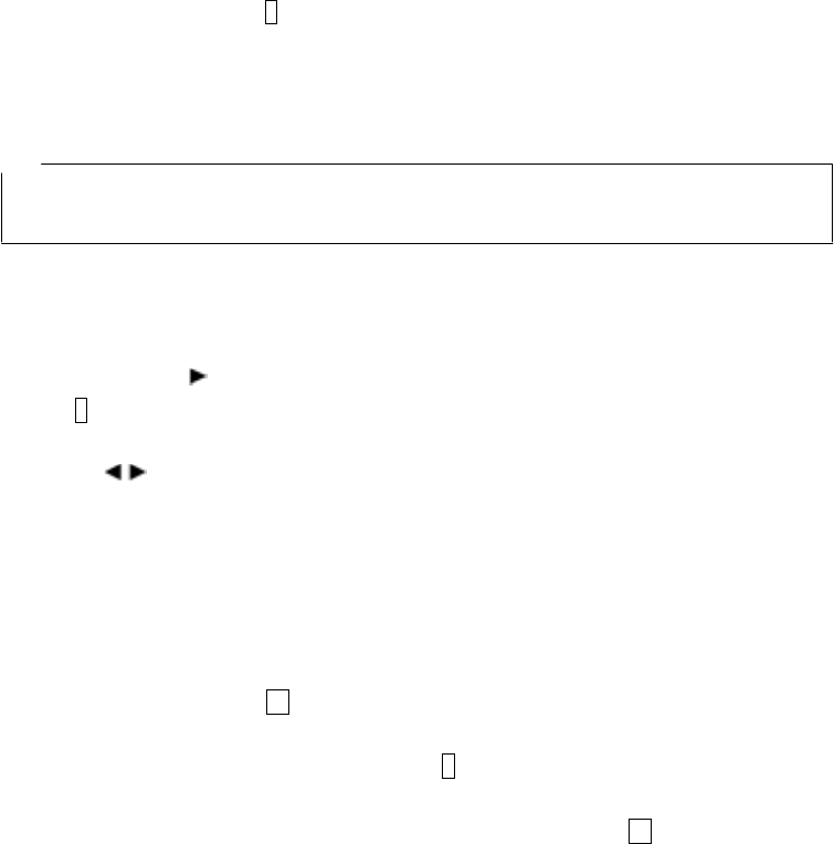
Figure 3-10 B-mode/BA-mode Display
3.3.2 Sensitivity switching
As sensitivity can be switched for the scan test results in the same way as during scanning,
scanning does not have to be performed again after changing sensitivity.
Sensitivity is displayed, for example, as "A shallow." "A" indicates the overall sensitivity; "shallow"
indicates sensitivity to depths.
There are five levels for overall sensitivity: "-2, -1, A, +1, +2." In general, use the unit in the "A"
setting. Use the +side to increase sensitivity and use the –side to reduce sensitivity.
There are two levels for depth sensitivity: "shallow and deep." Select "shallow" when the object to
be probed is at a depth less than 10 cm. Select "deep" when the object to be probed is at a depth
of 10 cm or more.
To change the sensitivity, press 3 GAIN . The sensitivity is changed as follows:
A, shallow → +1, shallow → +2, shallow → -2, deep → -1, deep → A, deep → +1, deep →
→ +2, deep → -2, shallow → -1, shallow → A, shallow → +1, shallow →
Remarks
If sensitivity is changed when scanning is stopped and scanning is performed again, the new
sensitivity set while scanning was stopped will be used for scanning.
3.3.3 Cursor operation
Figure 3-11 shows sample display with cursor operation.
(1) Cursor Display
If the cursor keys , ▼ are pushed after scanning is complete, a vertical cursor is displayed
on the 1 liquid crystal display screen.
The cursors on the screen move vertically when the ▲▼ keys are pressed, and horizontally
when the keys are pressed. The distance and depth at the intersecting point are displayed
in the upper area of the screen.
If the scan test data does not fit into the scan test screen, the vertical cursor disappears when it
reaches the right or left end of the screen, and the scroll mode is enabled to continuously display
the data stored in the memory.
(2) Cursor Mark Display
With scanning stopped, if the vertical/horizontal cursor intersection point is moved to the
position of the rebar etc. and 10 MARK is pushed, a cursor mark (▼ symbol and number) is
displayed at the cursor intersection point. The coordinates of the cursor mark are distance moved
and depth and are shown on the right side of the 1 liquid crystal display. Up to seven cursor
marks can be displayed.
To delete a cursor mark, move the cursor onto the cursor mark and press 10 MARK.
- 43 -
Remarks
• When switching from a scanning stopped state to scanning state, all of the cursor marks are
erased.
Cursor coordinates
Cursor mark coordinates
Cursor Mark
Cursor
Figure 3-11 Cursors and Cursor Marks
- 44 -
3.4 Image Processing
Image processing is processing that is performed on data input through scanning and enables
easy deciphering of objects that are being probed for from the scanning results.
This radar contains the following five types of image processing:
a)
b)
c)
d)
e)
Manual surface wave processing
Peak processing
Reproduction of original image
Fixed surface wave processing
Deduction processing
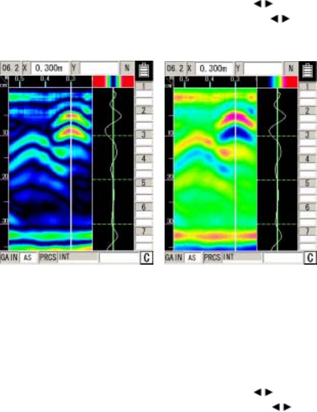
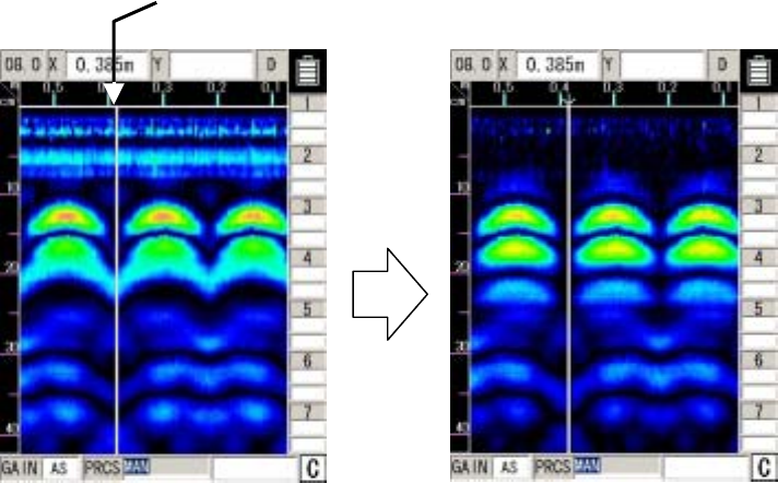
3.4.1 Manual surface wave processing
Manual surface wave processing is used when the effect of reflection near the surface of the
concrete on the scanning results can not be completely removed. (See Figure 3-12.)
(1) Move the cursor to a location where there is not an object that is being
probed
A: Before processing B: After processing
Figure 3-12 Display before/after Manual Surface Wave Processing
- 45 -

The operation is performed as described below.
a) a) Press the 6 PRCS key .
“Inverted display” is shown as the item for “Processing” at the bottom of the screen and
operation switches to image processing.
b) Set "Manual" using the cursor keys ▲▼.
c) Use the cursor keys to move the cursor to a location where there is not a object to
be probed in the sense test results. (See Figure 3-12 A-(1))
d) Press 5 ENTER . Manual surface wave processing will be performed while the reflected
wave at the cursor position is used as the surface wave. At this time, the mark "↓" is
displayed at the previous cursor position.
(See Figure 3-12B.)
e) To end the image processing mode, press the 6 PRCS key again.
“Normal display” is shown as the item for “Processing” at the bottom of the screen and
image processing mode is exited.
Remarks
• When "Manual" is set with the cursor keys ▲▼ after manual surface wave processing
(including real-time manual deduction processing) and deduction processing, image data will
be displayed using manual surface wave processing that uses the surface wave at the cursor
position (indicated by “↓”) of the last-executed processing. (Manual surface wave processing
can be newly performed by moving the cursor and pressing 5 ENTER.))
→ See section 3.2.5 “Real Time Manual Deduction processing” regarding real time
manual deduction processing.
• If manual surface wave processing and deduction processing (including real time manual
surface wave processing) after scanning are not performed, the image does not change
when the cursor keys ▲▼ are used to set operation to “manual”.
(Manual surface wave processing can be performed by moving the cursor and pressing 5
ENTER.))
• To perform manual surface wave processing again, repeat steps c) and d).
• Manual surface wave processing and deduction processing are almost the same but have a
different depth processing range.
• Manual surface wave processing: area where the effect of surfaces waves is high
• Deduction processing: full scanning depth
→ See "Section 3.4.5 Deduction processing" regarding deduction processing.
- 46 -

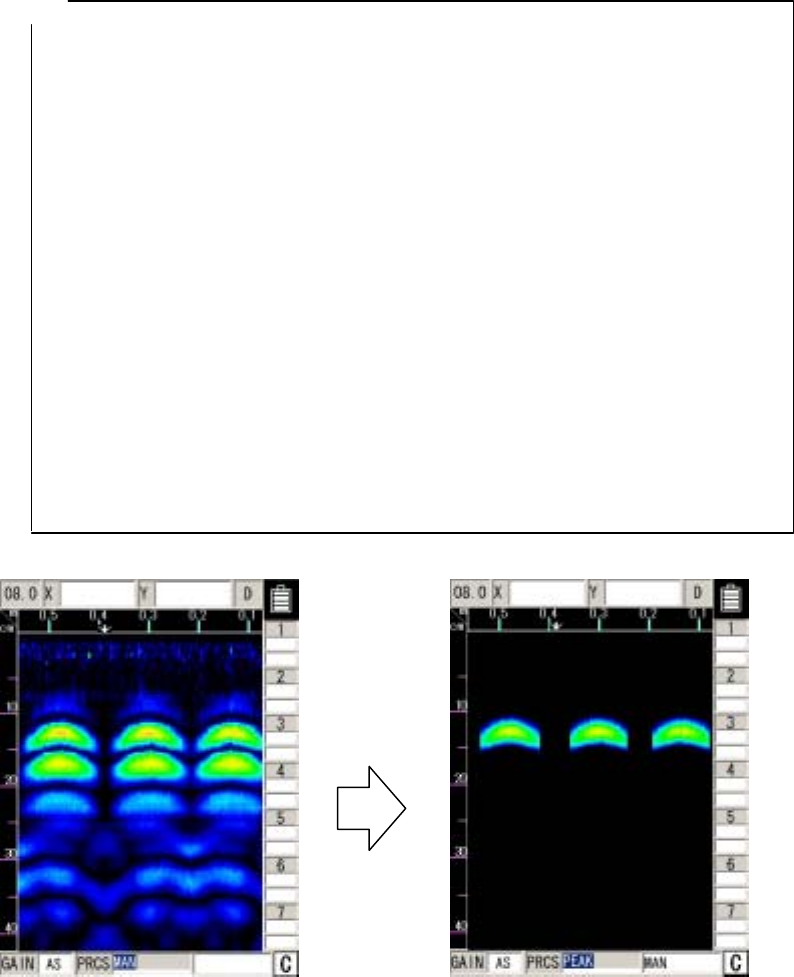
3.4.2 Peak Processing
Peak processing deletes multiple reflected waves of surface wave processing results and displays
only the reflected waves from objects being probed (rebar etc.). Use this when it is difficult to see the
depth of the objects being probed due to multiple reflected waves.
Note that peak processing cannot be used for probing objects (e.g., cavities) that have a lower
relative permittivity than concrete.
Peak processing can be performed for the results of fixed surface wave processing (including
real-time automatic surface wave processing), manual surface wave processing (including real-time
manual surface wave processing), and deduction processing.
Procedure for reduction processing:
a) a) Press the 6 PRCS key.
“Inverted display” is shown as the item for “Processing” at the bottom of the screen and
operation switches to image processing.
b) Set "Peak" using the cursor keys ▲▼.
c) c) Select “Peak manual," “Peak fixed," or “Peak deduction" using the cursor keys .
Peak processing will be performed for the relevant process results.
d) To end the image processing mode, press the 6 PRCS key again.
“Normal display” is shown as the item for “Processing” at the bottom of the screen and
image processing mode is exited.
Figure 3-13 shows sample display when peak processing is performed for the result of manual
surface wave processing.
- 47 -
Remarks
• The display items at the bottom of the screen and their meanings are as follows:
• Peak manual: Peak processing for the result of manual surface wave processing
• Peak fixed: Peak processing for the result of fixed surface wave processing
• Peak deduction: Peak processing for the result of deduction processing
• If “Peak manual" or “Peak deduction" is set without manual surface wave processing or
deduction processing being performed after scanning, the same data as when “Peak fixed" is
set will be displayed.
• If reflected waves shaped as horizontal stripes appear near the surface of concrete after
scanning (with automatic real-time surface wave processing performed), the setting of “Peak
fixed" may cause waves reflected by the reinforcing steel bars to be invisible due to the
remaining horizontal stripes.
In this case, use the following method (1) or (2) to solve the problem:
1. Perform manual surface wave processing for scanning results to eliminate
the reflected horizontal stripe waves from the data, and then perform “Peak
manual."
2. Perform deduction processing for scanning results to eliminate reflected
horizontal stripe waves from the data, and then perform “Peak deduction."
A: Before processing B: After processing
Figure 3-13 Peak processing
- 48 -
3.4.3 Reproduction of original image
This processing restores the image processing result to the original state and displays
unprocessed raw data.
Procedure for reduction processing: (See Figure 3-14.)
a) a) Press the 6 PRCS key.
“Inverting display” mode will be indicated at the bottom right hand side of the screen as
the operation switches to image processing from the manual mode..
b) Set "Original image" using the cursor keys ▲▼. Reproduction of original image will be
performed.
c) To end the image processing mode, press the 6 PRCS key again.
“Normal display” is shown as the item for “Processing” at the bottom of the screen and
image processing mode is exited.
A: Before processing B: After processing
Figure 3-14 Reproduction of original image
- 49 -
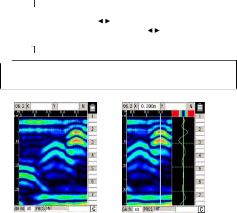
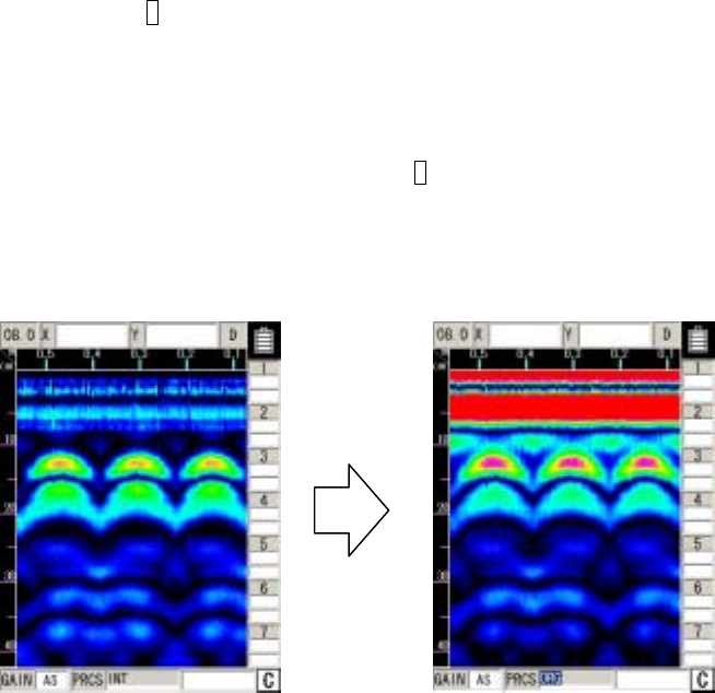
3.4.4 Fixed surface wave processing
This image processing displays surface processing results using internal fixed surface waves.
(Same as real time automatic surface wave processing results)
Procedure for reduction processing:
a) a) Press the 6 PRCS key.
“Inverting display” mode will be indicated at the bottom right hand side of the screen as
the operation switches to image processing from the manual mode.
b) Set "Fixed" using the cursor keys ▲▼. The result of surface wave processing performed
with the fixed surface wave will be displayed.
c) To end the image processing mode, press the 6 PRCS key again.
“Normal display” is shown as the item for “Processing” at the bottom of the screen and
image processing mode is exited.
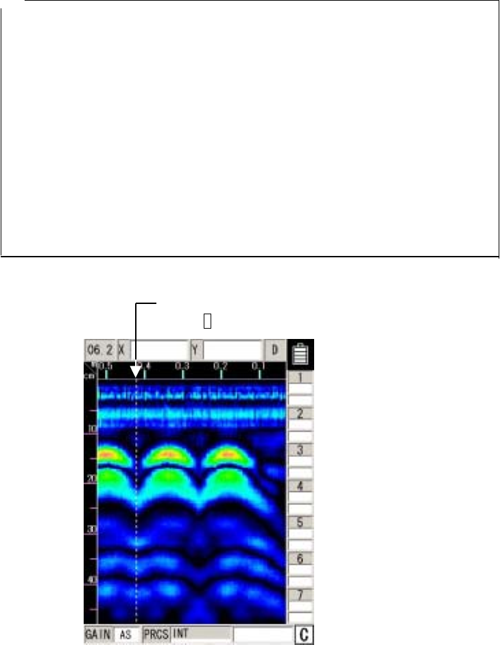
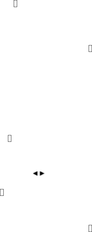
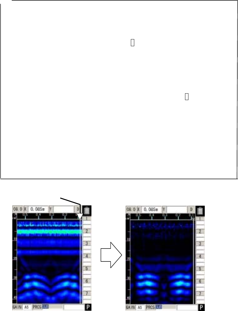
3.4.5 Deduction processing
Deduction processing eliminates reflected horizontal stripe waves from the screen after
completion of scanning for extremely deep depths of 20 cm or more as shown in Figure 3-15A.
Procedure for reduction processing:
a) Press the 6 PRCS key.
“Inverting display” mode will be indicated at the bottom right hand side of the screen as
the operation switches to image processing from the manual mode.
b) Set "Deduction" using the cursor keys ▲▼.
c) Use the cursor keys to move the cursor to a location where there is not a object to
be probed in the scan test results. (See Figure 3-15 A-(1))
d) Press 5 ENTER. Deduction processing will be performed with the reflected wave at the
cursor position.
At this time, the mark "È" is displayed at the previous cursor position. (See Figure 3-15
B.)
e) To end the image processing mode, press the 6 PRCS key again.
“Normal display” is shown as the item for “Processing” at the bottom of the screen and
image processing mode is exited.
- 50 -
Remarks
• When "Deduction" is set with the cursor keys ▲▼ after manual surface wave processing
(including real-time manual deduction processing) and deduction processing, the image
generated through deduction processing using the reflected wave of cursor position
(indicated by “↓”) of the last executed processing is displayed. (Deduction processing can be
newly performed by moving the cursor and pressing 5 ENTER.))
→ See section 3.2.5 “Real Time Manual Deduction processing” regarding real time manual
deduction processing.
• If manual surface wave processing and deduction processing (including real time manual
deduction processing) after scanning are not performed, the image does not change when
the cursor keys ▲▼ are used to set operation to “deduction”.
(Deduction processing can be performed by moving the cursor and pressing 5 ENTER.))
• To perform deduction processing again, repeat steps c) and d).
• Manual surface wave processing and deduction processing are almost the same but have a
different processing range.
• Manual surface wave processing: area where the effect of surfaces waves is high
• Deduction processing: full scanning depth
Deduction processing may eliminate reflected waves such as waves reflected by the rear
surface of a concrete wall.
→ For details, see "Section 3.4.1 Manual surface wave processing.
A: Before processing B: After processing
Figure 3-15 Display before/after Deduction Processing
- 51 -
3.5 How to Determine Depths and Sample Scan Test Data
The reflected waves shown in the scan test example in Figure 3-16 are reflections of rebar. (↓
position)
The position of the object to be probed (e.g., reinforcing steel) in the traveling direction is
determined as the peak of the reflected wave.
An approximate depth (covering depth) of the object to be probed (e.g., reinforcing steel) is
determined as the center of the reflected wave.
Perform depth calibration (see section 3.2.6 “Depth Calibration”) to reduce the error in the depth
(covering depth) of the object being probed (such as rebar). Use the A mode waveform from BA
mode (see section 3.3.1 “Mode Switching”) to determine the position of the object to be probed.
The position of the object to be probed (such as rebar) is shown by the peak on the right side of
the A mode waveform.
Match the cursor to the peak position to determine the depth.
- 52 -
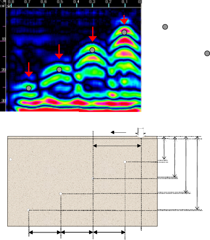
Position of rebar shown
among the reflected
waves of the scan tes
t
results (The
mark i
s
not actually shown in th
e
sense test result
s
.
)
200mm 200mm
200mm
60mm
120mm
180mm
240mm
: φ=10mm 鉄筋
300mm
測定方向 ート
ob
j
ect t
o
be
p
robed
ス
n
スタ
タ位置
S position
Vertical cross sectional drawing of
Measurement directio tart
200mm
200mm
200mm
60mm
120mm
180mm
240mm
: φ=10mm 鉄筋
300mm
測定方向 ート位置
Vertical cross sectional drawing
of object to be probed
Measurement direction Start
Φ=10cm rebar
Figure 3-16 Scan test example
- 53 -

3.6 External Output Methods
This unit is equipped with functions for printing the screen to a special printer (option) and a function
for saving scan test data to a compact flash memory card.
The following explains how to use the functions:
3.6.1 Printer Output
(1) Setting of an output destination
Press the 4 SET key on the scan test screen, and set "Printer (I)" for "External output" on the
parameter setting screen.
(2) Installation of the printer
Set up the printer so that the IrDA optical receiver faces the IrDA optical receiver on the front of
this unit at a distance of between 50 and 500 mm.
Note that if there is an obstacle between the radar and printer or the printer is not
installed at an angle of ±15 degrees, the printer is unable to operate.
(3) Printing
Pressing the 13 OUTPUT key enables printing to the printer.
Data in the range from 0 m (0 s) up to the currently displayed screen contents will be printed.
During output to the printer, "Date, Data No." as well as the message "Under printing" will be
displayed on the LCD screen.
Notes
● Use the designated (recommended) printer.
- 54 -
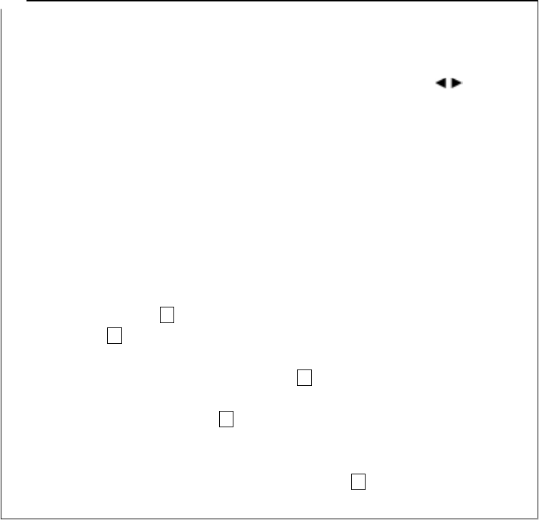
Remarks Remarks
• For details on the printer, see the printer instruction manual. • For details on the printer, see the printer instruction manual.
• To stop in the middle of printing, press any key. • To stop in the middle of printing, press any key.
• The printing range is from 0 m (0 s) up to the currently displayed screen contents. To print all
the scan test data, scroll to the last scan test screen using the cursor keys , and then
start printing.
• The printing range is from 0 m (0 s) up to the currently displayed screen contents. To print all
the scan test data, scroll to the last scan test screen using the cursor keys , and then
start printing.
• The direction of printed image data changes depending on the setting of the screen inversion
function. For the printer to always output image data in the same direction, retain the same
setting "Normal or Reverse" for "Inversion of the screen."
• The direction of printed image data changes depending on the setting of the screen inversion
function. For the printer to always output image data in the same direction, retain the same
setting "Normal or Reverse" for "Inversion of the screen."
See section 2.3.2 “Inverting the Screen” regarding inverting of the screen. See section 2.3.2 “Inverting the Screen” regarding inverting of the screen.
• As the voltage of the printer's battery pack lowers, the printing speed decreases. Replace the
battery pack as soon as a sign of a voltage drop is detected.
• As the voltage of the printer's battery pack lowers, the printing speed decreases. Replace the
battery pack as soon as a sign of a voltage drop is detected.
• When the message "Charge the printer's battery" is displayed on the screen, the voltage of the
printer's battery pack has lowered.
• When the message "Charge the printer's battery" is displayed on the screen, the voltage of the
printer's battery pack has lowered.
In this case, charge the battery pack or change to a new battery pack according to the
message, and press the 13 OUTPUT key again to start printing.
In this case, charge the battery pack or change to a new battery pack according to the
message, and press the 13 OUTPUT key again to start printing.
• If pressing the 13 OUTPUT key does not start printing and the message "Turn OFF/ON the
printer" is displayed, the printer settings may have been initialized. (The system may take
about 30 seconds to display this message after the 13 OUTPUT key is pressed.)
• If pressing the 13 OUTPUT key does not start printing and the message "Turn OFF/ON the
printer" is displayed, the printer settings may have been initialized. (The system may take
about 30 seconds to display this message after the 13 OUTPUT key is pressed.)
In this case, turn OFF/ON the printer according to the message. The printer will be set again
and get ready for printing. Press the 13 OUTPUT key again to start printing.
In this case, turn OFF/ON the printer according to the message. The printer will be set again
and get ready for printing. Press the 13 OUTPUT key again to start printing.
• When the message "No printing paper" is displayed on the screen, the printer has run out of
paper.
• When the message "No printing paper" is displayed on the screen, the printer has run out of
paper.
In this case, load a new roll of printing paper, and press the 13 OUTPUT key again to start
printing.
In this case, load a new roll of printing paper, and press the 13 OUTPUT key again to start
printing.
- 55 -
- 55 -

3.6.2 Data saving in compact flash memory
Notes ● Mount/remove the compact flash memory card while the power switch of this unit
is off.
● Make sure of the insertion direction before mounting the compact flash memory card.
● Operation of this unit has been confirmed with compact flash CF115-512M manufactured
by IO Data. The unit may not operate with a compact flash memory card of another company,
so an IO Data compact flash memory card should be used.
● Be sure to initialize the compact flash memory using this unit. If this is performed
using other equipment (NJJ-95B, PC etc.) the compact flash may not be recognized.
● Please do not use a compact flash memory that was used with a NJJ-95A. As the
data format used by NJJ-95A and NJJ-95B are different, this may cause an error.
This unit can save sense testing results as data to a compact flash memory card.
There are two types of data save formats: binary format and text format.
(1) Binary format
a) Configuration
The data format in binary mode consists of the following two sections:
Header section (ASCII data) + data section (binary data)
The header section contains information incidental to the scan test data (date, scan test
parameters, scan test data size, etc.).
The data section contains data attributes and scan test data.
- 56 -

b) Header section
The following shows a sample configuration of the header section and explains the
items.
The control codes in the header section are as follows: [0x0D] = CR, [0x0A] = LF, and
[0x1A] = EOF.
Sample configuration of the header section:
(1)NJJ-95 B Measurement Data ###[0x0D][0x0A]
(2)Date : 31.12.06[0x0D][0x0A]
(3)Time : 23:59[0x0D][0x0A]
(4)Data # : 999[0x0D][0x0A]
(5)X Data Size : 3000[0x0D][0x0A]
(6)Y Data Size : 512[0x0D][0x0A]
(7)X Scale : Distance[0x0D][0x0A]
(8)Y Scale : 06.2[0x0D][0x0A]
(9)X Scale Adjust : +5[0x0D][0x0A]
(10)Y Scale Range: 6ns[0x0D][0x0A]
(11)MarkX 1 : 3[0x0D][0x0A]
(12)MarkY 1 : 14[0x0D][0x0A]
(13)MarkX n : 2997[0x0D][0x0A]
(14)MarkY n : 508[0x0D][0x0A]
(15)END[0x0D][0x0A]
(16)[0x1A] [0x0D][0x0A]
Items in the header section:
(1)ID data such as the model name
(2)Date
(3)Time
(4)Data No.: 000 to 999
(5)Number of lines: 1 to 3000
(6)Number points per line: 512 (fixed value)
(7)Scan test system: "Distance" for distance feed, and "Time" for time feed
(8)Depth calibration value: 06.0 to 11.0, or ns
(9)Distance error compensation value: -20 to +0 to +20
(10)Shows the display range when saving: shallow
= 4ns, standard = 6 ns, deep = 8 ns
(11) X coordinate of the 1st cursor marker: Shown by line No.
(12) Y coordinate of the 1st cursor marker: Shows the point No.
(13) X coordinate of the n-th cursor marker: Max. n = 7
- 57 -
(14)Y coordinate of the n-th cursor marker
(15) Header section ending data
(16)EOF
c) Data section
Scan test data is configured as a collection of 1-line data.
One-line data is fixed to a length of 769 bytes as follows:
1 byte of header + 768 bytes of scan test data = 769 bytes
The header represents line attributes in the following format:
A0-Bit7(MSB) 0
A0-Bit6 0
A0-Bit5 1 when this line contains an antenna marker; 0 when it does not.
A0-Bit4 1 when this line is specified as the surface wave; 0 when it is not
A0-Bit3 0
A0-Bit2 0
A0-Bit1 0
A0-Bit0(LSB) 0
- 58 -

Details on 768 bytes of scan test data:
Scan test data per line includes 512 points, and 1-point data consists of 12 unsigned
bits.
Two-point data is sent after being re-listed as 3 bytes, so a total of 512 points (= 768
bytes) are sent.
Data is re-listed according to the rule shown below.
[0xABC]+[0xDEF]→[0xAD]+[0xBC]+[0xEF]
Following the fixed surface wave data, the single-line scan test data explained above is
output for each scan test line. The header of the fixed surface wave data is [0xFF].
Therefore, the length of the data section is variable:
(1 byte of header + 768 bytes of scan test data) x (number of scan test lines +1)
(number of measurement lines + 1)
(2) Text mode
a) Configuration
The data format of the text mode is the same as for the binary mode.
The difference from the binary mode is that the text mode processes all data as ASCII
data.
Header section (ASCII data) + data section (ASCII data)
b) Header section
The configuration of the header section is the same as for the binary mode.
c) Data section
The text mode converts one byte of data output by the binary mode to two bytes of
ASCII data (HEX) and outputs the converted data with [0x0D] and [0x0A] being added.
Remarks
• The size of data in binary mode is smaller than that in text mode, thereby saving
space of the compact flash memory.
• The saved data is A/D conversion data (original image data), but not the one after image
processing such as surface wave processing has been performed.
- 59 -
(3) Saving data to compact flash memory
Procedure for saving data in compact flash memory:
a) Setting of an output destination
Press the 4 SET key on the scan test screen, and set "CF (text)" or "CF (binary)" for
"External output" on the parameter setting screen.
b) Setting of a data number
An arbitrary number can be assigned to scanned data by setting the number for "Data
No." on the parameter setting screen. The data number (Data No.) is incremented each
time data is saved.
c) Saving of sense test data
If the 13 OUTPUT key is pressed while a scan test is stopped on the scan test screen,
data from scan testing can be saved to a compact flash memory card.
The file name of saved data is determined as follows:
B1230450.001
Data No.
Scan test time: The first 2 digits indicate hours; the last 2 digits
indicate minutes.
Scan test date
Scan test month month: A, B, and C stand for October, November, and
December, respectively.
Save format: T stands for text format; B stands for binary format.
d) Confirmation of data saved
Press the 12 CF button. The screen will be switch to the CF control screen shown in
Figure 3-17 where you can check whether data has been saved. On the CF control
screen, you can also display the thumbnail images of saved data, read/delete
data, and initialize the compact flash memory. For details, see "Section 3.7 CF
Control Screen."
- 60 -
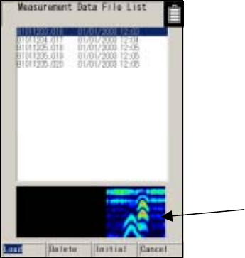
Display of thumbnails
Figure 3-17 CF Control Screen
- 61 -
3.7 CF Control Screen
When not scan testing, if the 12 CF button is pushed, operation will be switched to the CF control
screen. Once at the CF control screen, thumbnail image display can be viewed. Also, data storage,
data erasure, and initialization for the compact flash memory card can be executed.
To return to the measurement screen, select "Cancel" using the cursor keys , and press the
ENTER key or the 12 CF button.
All of the functions of the CF control screen are shown below.
3.7.1 Displaying the thumbnail images of saved data
When a file is selected at the CF control screen using the ▲▼ cursor keys, scan test results can
easily be displayed on the display area. (See Figure 3-17.)
The thumbnail display enables an easy check on saved image data.
If "Monochrome" is selected for "Display color" on the setting screen, the thumbnail image display
will also be monochrome.
3.7.2 Reading saved data
To open data that has been saved, select the file to be opened using the ▲▼ cursor keys on the
CF control screen, select “Open” using the keys and press the ENTER key.
The screen changes to the scan test screen, the screen is scrolled, and the selected data is
opened.
"Read" is finished when the screen stops scrolling.
If there is data that has not been saved or data opened from the CF on the scan test screen prior to
switching to the CF control screen a message “Data that has not been saved will be erased – Yes/No”
is displayed. Select “Yes” using the keys and press the ENTER key to open the file. If “No” is
selected and the ENTER key is pressed, operation returns to the CF control screen. (See Figure
3-18.)
Operations such as changing sensitivity, image processing, external output (printing), and cursor
operations can be performed on the data that has been opened.
- 62 -
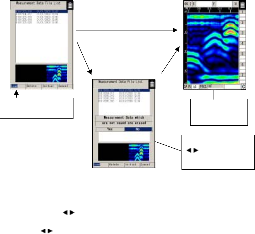
Select "Read" and press the The screen scrolls
ENTER key. while data is being
read.
Figure 3-18 Reading Saved Data
3.7.3 Deleting saved data
Select the file to be deleted on the CF control screen using the cursor keys ▲▼, select "Delete"
using the cursor keys , and press the ENTER key.
When the message "Do you want to delete the data? Yes/No" is displayed, select "Yes" using the
cursor keys , and press the ENTER key. (See Figure 3-19.)
Select “Yes” using
key and push th
e
ENT
th
e
ER key
A
n example where there is dat
a
that has not been saved or dat
a
opened from CF on the scan tes
t
screen
If there is not any data or dat
a
opened from CF on the scan tes
t
screen
(To cancel the deletion, select "No" and press the ENTER key.) )
- 63 -
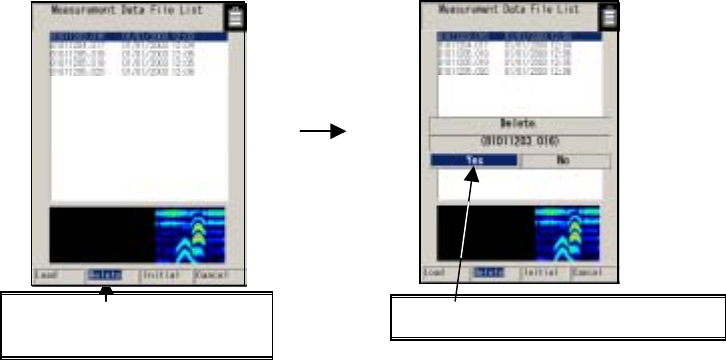
To delete the data, select "Yes" and Select "Delete" and press the ENTER key.
press the ENTER key.
Figure 3-19 Deleting Saved Data
- 64 -

3.7.4 Method for initialization of Compact Flash
Select "Initialization" on the CF control screen using the cursor keys , and press the ENTER
key.
The message "Do you want to initialize memory? Yes/No" is displayed. Select "Yes" using the
cursor keys , and press the ENTER key. (To cancel the initialization, select "No" and press the
ENTER key.)
The message “Initializing” is displayed and initialization is started. After the message disappears,
the compact flash memory is initialized and all data is deleted. (See Figure 3-20.)
Notes
• Never remove/insert the compact flash memory card or turn off the power switch while
initializing is in progress. Doing so may cause a malfunction.
• Be sure to initialize the compact flash memory using this unit.
• If the CF button is pressed without a compact flash memory card being mounted, the
message "No compact flash memory" will be displayed. In this case, press the ENTER key
to close the screen, turn off the power, and then insert the compact flash memory card.
- 65 -
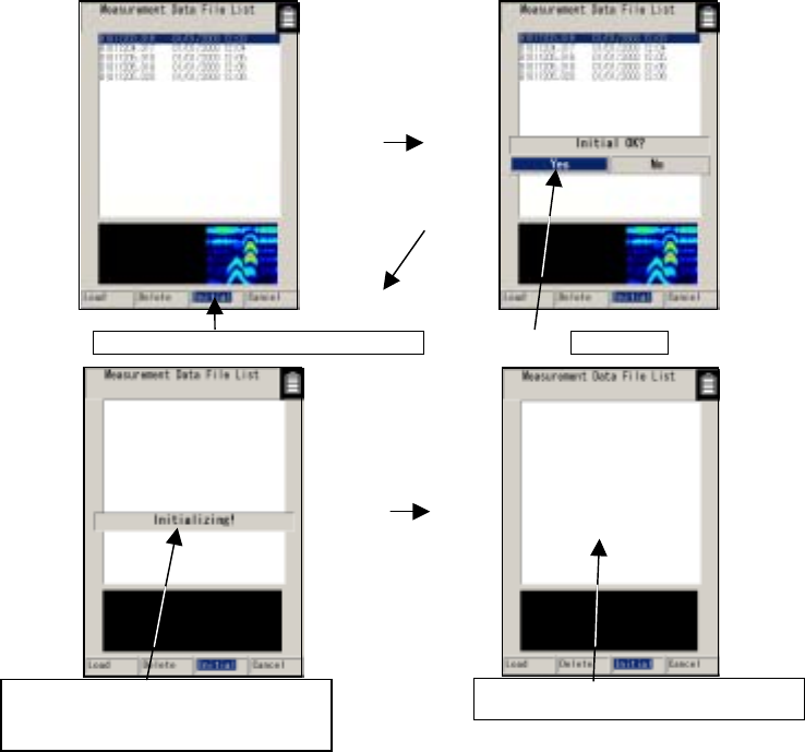
Press the ENTER key to start initialization Select "Yes"
Message indicating compact flash After initialization, all data is erased
memory is being initialized
Figure 3-20 Initializing Compact Flash Memory
- 66 -

3.8 Power-off Procedure
When scan testing is finished, set the 16 power switch to "OFF."
Notes
• All scan test data that is not saved in the compact flash memory is deleted when the power is
turned off.
3.9 Clearing up the radar and accessories
Turn off the power, disconnect all cables the radar, and put them together with the radar into the
provided storage box.
Remarks
● If this radar is not to be used for a long time, dismount the battery pack when storing the
radar.
- 67 -
3.10 About the Battery Pack and Charger
WARNING
Do not short-circuit the terminals of the battery charger or battery pack.
Doing so could cause fire, explosion, or breakdown.
Do not disassemble, modify, heat, or throw the battery pack on fire.
Doing so could cause fire, explosion, or breakdown.
Do not use any charger other than the dedicated battery charger to charge the battery pack.
Doing so could cause fire, electric shock, or breakdown.
Do not connect/disconnect the plug while your hands are wet.
Doing so could cause an electric shock.
Stop using the NJJ-95B immediately when a possible malfunction is detected, and follow only
the detailed procedure in this instruction manual. If it cannot be restored to normal operation,
contact our nearest branch office, sales outlet, or service station. Use of the NJJ-95B in
abnormal state could cause fire or breakdown.
Should the NJJ-95B emit an abnormal sound, odor, or smoke, immediately turn off the power
switch, remove the battery pack, disconnect the power plug from the socket outlet, and
contact our nearest branch office, sales outlet, or service station.
Use of the NJJ-95B in abnormal state could cause fire, electric shock, or breakdown.
CAUTION
Do not use any battery pack other than the BP-3007-A1.
Doing so may cause fire, electric shock, or breakdown.
- 68 -
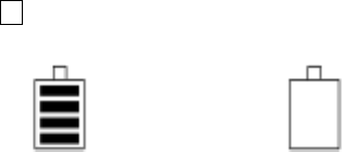
3.10.1 Battery pack BP-3007 series
The battery pack BP-3007 series, which is commonly used with the Handy Search and printer
(optional), contains a rechargeable lithium ion battery.
While the battery pack is fully charged, it can operate the Handy Search for about 1.5 hours.
(1) Mounting/dismounting the battery pack
See "Section 3.1 Preparations for Sense Testing", for how to mount/remove the battery
pack.
(2) Battery pack remaining capacity
The battery availability indicator is displayed at the upper right of the LCD screen of this
radar.
When the battery availability indicator shows the "0" state (see Fig. 3-21) and the buzzer
sounds, set the 16 power switch to "OFF" and replace the battery pack.
Fully charged state Availability "0" state
Figure 3-21 Battery pack capacity indicator
(3) Usage of the charging check mark
Use the green charging check mark (see Fig. 3-22 A) to check if the battery pack has been
used after being charged.
・ The mark turns green when the battery pack is removed from the dedicated battery
charger.
・ This mark can also be switched by hand.
- 69 -

Remarks
• The battery pack is charged just enough for the radar's test operation before it is shipped.
The battery pack needs to be charged when used for long operation.
• The battery pack should be charged immediately before being used.
• Keep the battery pack in as cool a location as possible to make it last longer and it is
recommended to charge the battery in an area with a temperature between +10 and +30 °C.
• The battery pack's operating time is shortened in a cold region.
• The battery pack does not need to be discharged or used up before it is charged.
• It is considered that the battery pack has reached its service life when the operating time
sharply decreases. Change to a new battery pack.
• When using the battery pack, be careful that any foreign matters like dust or sand do not get
into the terminals (see Fig. 3-22 B). If foreign matters have got into the terminals, remove
them completely with soft, pointed sticks, and repeat mounting/dismounting it on/from the
battery charger several times until the terminals have good contact.
- 70 -
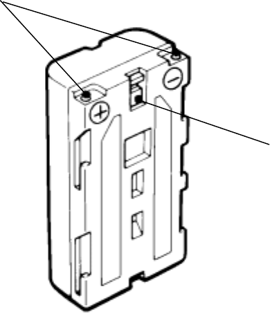
B Terminals
A
Charge
confirmation mark
Figure 3-22 Battery Pack
- 71 -

3.10.2 Charging Device BC-3008 series
The battery charger BC-3008-series is exclusively used with the battery pack BP-3007-series.
When the battery pack is in the availability "0" state, charging will take about 2.5 hours.
(1) Procedure for using the charger
a) Mount the battery in the charger (see Fig. 3-23-(1))
While pushing the battery pack against the charger, slide it in the direction indicated by
the arrow. Mounting of the battery pack is completed when it is pushed in until the shutter of
the charger is hidden.
b) Connect the AC cord to the charger
Connect the AC cable to the charger, and connect the AC cable plug to the socket
outlet. The CHARGE lamp (orange) on the charger will light indicating the start of charging.
(See Figure 3-23-(2).)
c) Completion of charging
When the CHARGE lamp goes off, the battery pack has been charged enough for
"practical use." The battery pack will be "fully charged" if it is charged for another hour
continuously after the lamp goes off.
d) Removing the battery
When charging is finished, remove the battery pack sliding it in the opposite direction
from the mounting, and disconnect the AC cable plug from the socket outlet.
Notes ● Thoroughly read the "charger instruction manual" to use the battery
charger correctly and safely.
● Charge the battery pack in a place where the ambient temperature is 0 to 35℃ and the
humidity is 45 to 90%.
● After using the battery charger, be sure to disconnect it from the socket outlet. Dismount
the battery pack from the charger within 24 hours after it has been charged.
Remarks
• Store the battery pack in a cool location to ensure the longevity of the battery. It is
recommended to charge the battery in an area with a temperature between +10 and +30
°C.
- 72 -
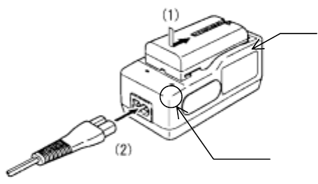
Shutter
Charge lamp
Figure 3-23 Battery Charger
- 73 -
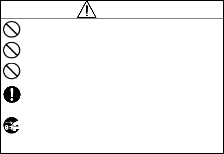
4 Options
WARNING
Do not use any battery pack other than the BP-3007-A1 or any AC adapter
other than the PW-3009-W.。
Doing so could cause fire, electric shock, or breakdown.
Do not short-circuit the terminals of the battery charger or battery pack.
Doing so could cause fire, explosion, or breakdown.
Do not insert anything metallic or flammable into the compact flash memory
card slot. Doing so could cause a personal injury, fire, electric shock, or
breakdown.
Stop using the NJJ-95B immediately when a sign of malfunctioning is
detected, and follow only the detailed procedure in this instruction manual. If
it cannot be restored to normal operation, contact our nearest branch office,
sales outlet, or service station. Use of the NJJ-95B in abnormal state could
cause fire or breakdown.
Should the NJJ-95B emit an abnormal sound, odor, or smoke, immediately turn off the power
switch, remove the battery pack, disconnect the power plug from the socket outlet, and
contact our nearest branch office, sales outlet, or service station.
Use of the NJJ-95B in abnormal state could cause fire, electric shock, or
breakdown.
- 74 -
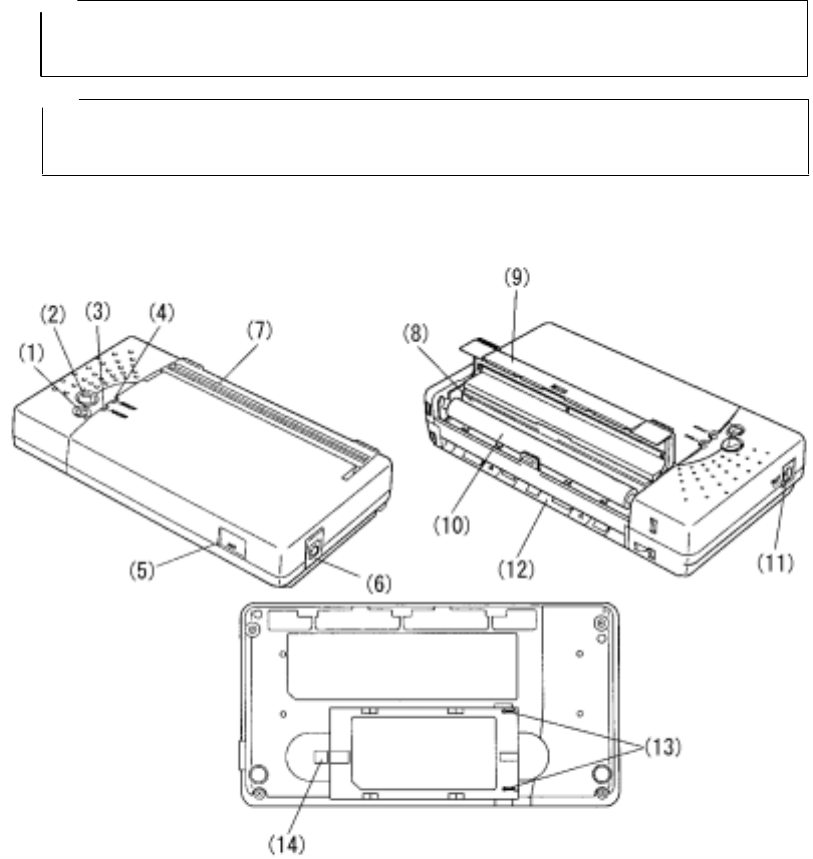
4.1 Printer DPU-3445 series
Printer DPU-3445-series is of the thermal type and prints out the records of data scan tested with
the Handy Search.
Notes
• Thoroughly read the "printer instruction manual" to use the printer correctly and
safely.
Remarks
• See Section 3.6 External Output Methods regarding Handy Search settings.
• For details on printer handling, see the printer instruction manual.
4.1.1 Printer's main parts names and functions
Figure 4-1 shows the main parts of the printer, and Table 4-1 explains their functions.
Figure 4-1 Printer's Main Parts
- 75 -

Table 4-1 Printer's Main Parts and Functions
No. Name Function
1 Power button
Turns "ON or "OFF" the power.
To turn on the power, hold the button down until the power lamp
turns on. To turn the power off, hold the button down until the
power lamp turns off.
2 FEED button Paper is fed a small amount each time this button is pressed.
To continuously feed paper, hold down the button.
3 POWER lamp Lights when the power is turned on.
4 ERROR lamp Lights when a printer error has occurred.
5 IrDA light receiver-emitter Light receiver-emitter for IrDA (infrared data communication)
6 Interface connector Connects the interface cable.
Open the rubber cover, and insert the connector.
7 Paper ejection port
Paper is ejected from this port equipped with a paper cutter.
While the platen cover is closed, paper is ejected from the top of
the printer.
8 Thermal head Records data on paper.
Be careful that the thermal head is hot immediately after printing.
9 Platen cover
The thermal head is released from paper when this cover is
opened.
Open the cover to remove paper or clean the thermal head.
10 Platen roller Brings the thermal head into contact with paper.
Paper is fed by turning the roller.
11 Power connector Connects the AC adapter.
12 Paper insertion port Paper is inserted through this port.
13 Battery connection terminal Used to connect the battery pack.
14 Button for releasing the
battery Used to remove the battery pack from the printer.
4.1.2 Printer Specification
The specification for the printer is shown below.
Printing system: :Thermal line dot system
Printing width/printing paper width: :104/112mm
Interface: :RS-232C, IrDA
Operating temperature range: :+5∼+40℃
External dimensions: :160 x 89 x 29.5mm
Weight: :About 250 g (the printer alone)
- 76 -
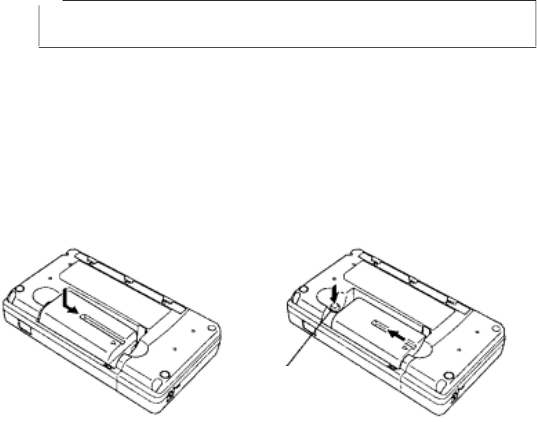
4.1.3 Connecting the battery pack/power source
Notes
• Confirm that the power switch is set to "OFF" before mounting/dismounting the battery pack
or the AC adapter.
(1) Mounting the battery pack (See Figure 4-2 A.)
Align the printer's battery connecting terminals with the battery pack's connecting terminals,
and push the battery pack in the direction indicated by the arrow.
(2) Removing the battery pack (See Figure 4-2 B.)
a) Turn the printer power switch "OFF".
b) Slide the battery pack in the direction indicated by the arrow while pushing the battery
release button.
Release button
A B
Figure 4-2 Connecting the Battery Pack
(3) When using the AC adapter:
a) Connect the output plug of the AC adapter to the "power connector."
b) Connect the AC adapter power cable to the socket outlet.
- 77 -
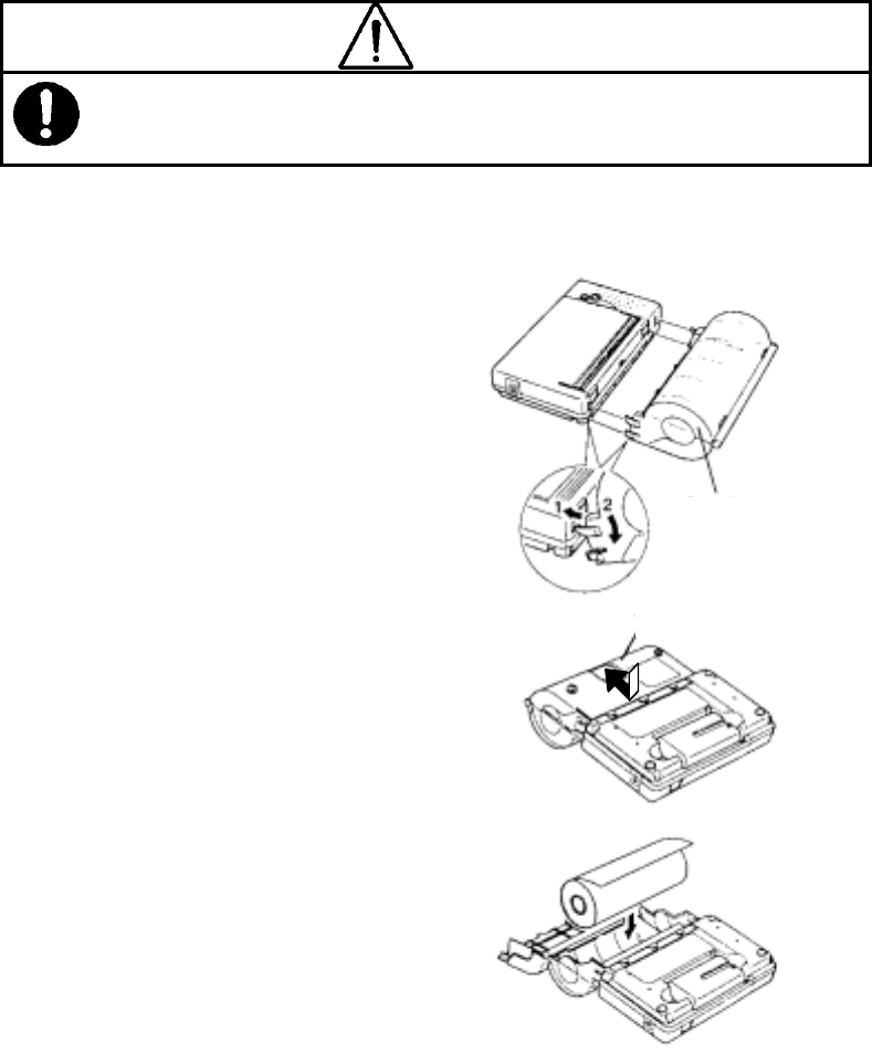
(4) Mounting the Paper Holder and Loading Paper
CAUTION
When loading/unloading printing paper, be careful not to cut or jam your fingers in the printer.
Mount the paper holder on the printer and then load paper.
A
B
1.Insert the paper holder hooks into the
square holes (upper) in both sides of the
platen cover of the printer.
(Arrow 1 in Figure 4-3 A.)
Then push in the paper holder while
hooking the paper holder claws in the
square holes (lower) in the printer.
Mounting is completed when a click sound
is heard. (Arrow 2 in Figure 4-3 A.)
2.Turn "ON" the printer power switch.
3.Place the printer upside down, and slide
the paper cover in the direction indicated
by the arrow while softly pressing the
center of the paper cover. The paper
cover is unlocked and can be opened.
(See Figure 4-3 B.)
4.Load a paper roll into the paper holder as
shown in Figure 4-3.
5.Insert the end of paper from the paper
insertion port as far as it will go. The
printer detects that paper has been loaded
and draws in the paper automatically.
(See Figure 4-3 D.)
Paper holder
Paper cover
Figure 4-4
Mounting the Paper Holder and Loading
Paper
C
Paper cover
Paper holder
- 78 -
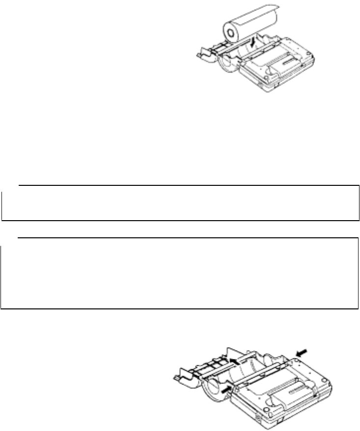
6.Close the paper cover, and slide it in the
opposite direction of step 3 until a click
sound is heard. The paper cover will be
locked.
Note that paper will drop if the paper cover
is not locked securely in this step.
Fig. 4-3 (continued)
Mounting the Paper Holder and Loading
Paper
D
7.Replace the printer to its original position.
The ERROR lamp is lighted in this state. Press the FEED button once to get the printer
ready for printing.
Notes
• Do not apply excessive force to the paper holder. Be careful, in particular, when releasing the
paper cover.
Remarks
• To unload paper, turn "OFF" the power, and then open the platen cover fully. Place the printer
upside down, and open the paper cover.
Then, simply lift the paper roll to remove.
• Insert the end of paper straight into the paper insertion port. Diagonal insertion may cause a
paper feed failure.
(5) Method for removing the paper holder
Perform the following procedure to dismount the paper holder. (See Figure 4-4.)
1.Remove the paper roll from the paper
holder.
2.While the paper cover is open,
simultaneously press the right and left
claws of the paper holder to unlock.
When the paper holder is unlocked, it
can be removed from the printer.
Figure 4-4
Dismounting the Paper Holder
(6) Connecting with the Handy Search
Set up the main unit (Handy Search) and the printer so that the IrDA optical
receivers are facing each other.
At this time, there is a range where printing is enabled through IrDA. Set the units
up with a distance of between 50 and 500 mm and an angle of within ± 15 degrees.
- 79 -
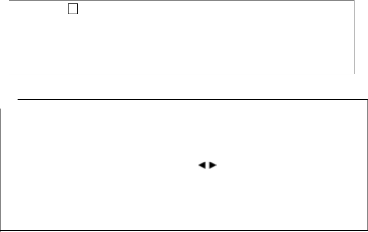
(7) Printing of Handy Search scan test data
Before starting to print, check the external output destination setting on the parameter
setting screen.
Make sure that external output is set to printer (I).
After the confirmation, return to the scan test screen, and perform the following printing
procedure:
a) Press the 13 OUTPUT key.
b) Data in the range from 0 m (0 s) up to the currently displayed screen will be printed.
c) During printing, the name of the file (“No Name Data” for case where the data was not
opened and has not been saved), date, data no. are displayed on the liquid crystal display
in addition to the message “Printing”.
Remarks
● See Section 3.6 External Output Methods regarding Handy Search settings.
● For details on printer handling, see the printer instruction manual.
● To stop in the middle of printing, press any key.
● The printing range is from 0 m (0 s) to the display screen. To print all the scan test data, scroll
to the last scan test screen using the cursor keys , and then start printing.
● The direction of printed image data changes depending on the setting of the screen
inversion function. For the printer to always output image data in the same direction, retain
the same setting "Normal or Reverse" for "Inversion of the screen."
See "Section 3.2.3 “Inverting the Screen” regarding inverting of the screen.
- 80 -
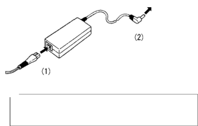
4.2 AC Adapter PW-0904-W1 series
The AC adapter PW-3009 series is used with both the Handy Search and printer.
4.2.1 AC Adapter Specification
The specification for the AC adapter is shown below.
Input voltage: :AC 100 to 240V
Output voltage :DC 9.3V
Output current :4A
Operating temperature range: :0∼+40
External dimensions: :110 x 62 x 30mm
Weight: :Approximately 300g
4.2.2 Connecting the AC adapter
(1) Confirm that the power switch on the main unit is set to "OFF."
(2) Connect the AC cable to the AC power connector on the AC adapter. (See Figure 4-5 (1))
(3) Connect the DC jack of the AC adapter to the connection destination equipment (Handy
Search/printer).
(See Figure 4-5 (2))
(4) Connect the AC adapter cable to the socket outlet.
To device
Figure 4-5 Connecting the AC Adapter
Notes
● Thoroughly read "AC Adapter Usage" to use the AC adapter correctly and
safely.
● Connect the AC adapter while the power switches on the radar and printer
are turned off.
- 81 -
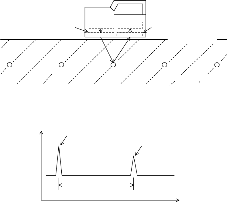
5 Theory
5.1 Principle of Operation
The principle of this radar is basically the same as for general radars widely used at present.
Electromagnetic waves are transmitted from the antenna toward the concrete as shown in Figure
5-1. The electromagnetic waves are reflected by an interface with the reflecting objects (e.g.,
reinforcing steel bars or cavities) whose electrical property is different from that of concrete. The waves
are reflected back onto the surface of concrete and received by the receiving antenna placed near the
concrete surface. The distance to the reflecting objects can be calculated from the time the reflected
waves need to reach the receiving antenna. The horizontal locations of the objects can be detected by
moving the main unit on the surface of concrete.
Since this radar is designed to probe objects with high resolution that are near from the surface of
concrete, it transmits pulse waves having a width of only about one nanosecond (one-billionth of a
second) or less.
Rec. Trans. Rec. antenna Trans antenna
Rebar Inside concrete
Concrete surface
Figure 5-1 Diagram of Principle
Figure 5-2 shows a wave reflected by a reinforcing steel bar or the like in a concrete structure, which
is obtained by this radar.
Reflection
Trans. wave
Reflected wave from rebar
Time
T
Figure 5-2 Sample of Reflected Waveform
- 82 -
Velocity V of electromagnetic waves in concrete is obtained from the following formula:
(m/s)
ε
C
V= r
C: Velocity of electromagnetic waves in vacuum (in air) (3 × 10⁸ m/s)
: Relative dielectric constant of concrete (6 to 11 in the example)
Distance D to the reflecting object is obtained from the following formula:
(m)VT
2
1
D=
5.2 Applicable Conditions
(1) Applicable measuring conditions
(Waves reflected by objects to be scan tested in reinforced concrete structures must be received
adequately, so the applicable measuring conditions vary slightly depending on the on-site condition.)
○ Scan test depth (covering depth) within 0.5 ~ 30 cm (case where relative permittivity of concrete
is 6.2 and the diameter of the rebar is at least 6mm)
○ Objects to be probed that are at a depth of less than 75 mm have an interval spacing of at least
75 mm and where the depth of the object to be probed is greater than 75 mm, the interval
spacing of the objects is more than the depth
○ Quality of concrete: Uniform
○ Direction of reinforcing steel: Orthogonal to the Handy Search's traveling direction
(2) Inapplicable measuring conditions
○ Scanning of reinforcing steel or the like in concrete whose surface contains objects such as
metal that reflect radio waves
○ Presence of reinforcing steel bars that are parallel to the Handy Search's traveling direction
○ Concrete that has a narrow (pitch) arrangement for the interval of rebar in the horizontal
direction
(Target: depth less than 75 mm → interval between rebar, less than 75 mm
Depth of greater than 75 mm → interval of rebar less than depth)
- 83 -
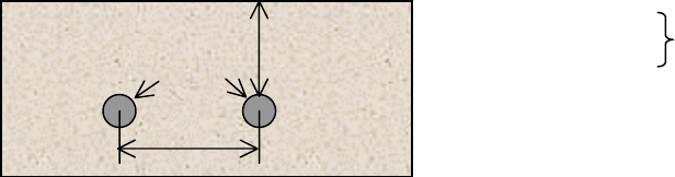
Concrete
Rebar
L
DD<75mm → L>75mm
D≤75mm → L≥D Difficult to implement
- 84 -
6 Maintenance Inspection
WARNING
Do not attempt to disassemble, modify, or repair the NJJ-95B.
Doing so could cause fire, electric shock, or breakdown.
When the power cord is damaged (exposed core wire, open circuit failure, or
broken sheath), please contact our headquarters on Page 93 or our nearest
branch office, sales outlet, or service station for a replacement power cord.
Use of a damaged power cord could cause fire or electric shock.
Stop using the NJJ-95B immediately when a sign of malfunctioning is
detected, and follow only the detailed procedure in this instruction manual. If it
cannot be restored to normal operation, contact our nearest branch office,
sales outlet, or service station. Use of the NJJ-95B in abnormal state could
cause fire or breakdown.
Should the NJJ-95B emit an abnormal sound, odor, or smoke, immediately turn off the power
switch, remove the battery pack, disconnect the power plug from the socket outlet, and
contact our nearest branch office, sales outlet, or service station.
Use of the NJJ-95B in abnormal state could cause fire, electric shock, or breakdown.
6.1 Daily Inspection
Before attempting to operate this radar, confirm that the battery pack, optional equipment cables,
and the like are connected correctly and there is no abnormality in appearance.
6.2 Daily Maintenance
Users are not to carry out any maintenance except for cleaning of the radar's external surfaces.
Wipe out stains with a soft damp cloth (which was squeezed of any excess water after being
soaked in cold or warm water), and then wipe the radar with a dry cloth again. Do not use solvents
such as thinner, benzine, and alcohol because they may damage the top finish of the radar.
- 85 -

6.3 Troubleshooting
The radar's states listed below are not always a sign of trouble.
Check for the radar again before asking for repair.
Main unit state Check Items and Response
The main unit cannot be
turned on.
Nothing is displayed.
• Check if the battery pack is mounted.
ÆMount a fully charged battery pack according to section 3.1
“Preparations for Scanning."
• Check if the battery pack is exhausted.
ÆMount a fully charged battery pack according to section 3.1
“Preparations for Scanning."
• Check if the power plug of the AC adapter is connected.
ÆConnect the AC adapter correctly according to section 3.1
“Preparations for Scanning."
• Check if the battery pack is mounted while the output plug of the
AC adapter is connected to the AC input connector on the radar.
ÆDisconnect the AC adapter according to according to section 3.1
“Preparations for Scanning," and operate the radar with the
battery pack.
The battery pack is
exhausted rapidly.
• Check if the battery pack is charged sufficiently.
→ Charge the battery pack fully according to section 3.10.2
“Battery charger BC-3008 series.”
• Has the battery pack itself reached the end of its life?
→ Exchange it for a new battery pack that is fully charged.
Sense testing does not
start when the START
key is pressed.
• Are you at the parameter settings screen?
→Return to the scan test screen following section 2.3 “Parameter
Settings Screen."
The B-mode display is
advanced when the
START key is simply
pressed.
• Check if "Time feed" is set as the sense test method.
→Set "Distance feed" according to section 2.3.5 “Sense Test
Method."
Printing is not started
when the OUTPUT key
is pressed.
• Check if "External output" is set correctly on the parameter setting
screen.
→Set it up correctly following section 3.6 “External Output."
- 86 -

Main unit state Check Items and Response
The message "Turn
OFF/ON the printer" is
displayed when the
OUTPUT key is pressed.
• Check if the printer settings have been initialized.
→Turn OFF/ON the printer, and press the OUTPUT key again to
start printing.
The message "Charge
the printer's battery" is
displayed when the
OUTPUT key is pressed.
• Check if the battery pack is exhausted.
→Mount a fully charged battery pack, and press the OUTPUT key
again to start printing.
The message "No
printing paper" is
displayed when the
OUTPUT key is pressed.
• Is the printer out of paper?
→Load a new paper roll, and press the OUTPUT key again to start
printing.
The message "Printer
error" is displayed when
the OUTPUT key is
pressed.
• Check if the printer displays an error message.
→Eliminate the cause of the printer error according to the printer
instruction manual.
“CF Not Available”
message appears if the
CF key is pushed
• Has the compact flash card been removed?
• Was the compact flash card inserted after turning the power on?
→ Whether or not compact flash is inserted is checked when the
power is turned on
Insert a compact flash card following section section 3.1
“Preparations for Sense Testing."
Data from the compact
flash card can not be
read
• Has the compact flash card been removed?
→ Insert a compact flash card following section 3.1 “Preparations
for Scanning."
• Is the file attempting to be read data from the NJJ-95B?
→ The NJJ-95B can not open data from the NJJ-95A. Please
check the data
The date/time indication
has been changed to
"0s."
Not trouble
The voltage of the internal button-type lithium battery has dropped.
The battery is rechargeable and is charged automatically when the
radar is used.Set the "date and time" according to section 2.3.7
“Date, time."
Continuous use warms
the casing. This is a normal phenomenom.
- 87 -
After-sales Service
If this radar malfunctions, read section 6.3 “Troubleshooting" carefully, and check the radar again. If
the radar still malfunctions, stop using it, and contact our nearest branch office, sales outlet, or service
station.
●Information to be reported
Product name, model number, and serial number
Detailed information about the abnormal state
Company/organization name, address, and telephone number
For inquiries about after-sales service, contact our nearest branch office, sales outlet, or service station.
“Contact information” is on page 93.
- 88 -

8 Disposal
WARNING
Before disposing of the used lithium ion battery, insulate the charging
terminals by taping or the like. Otherwise, the battery could cause fire or
explosion if short-circuited.
8.1 Disposal of Used Battery Pack
Discharge the used battery pack (lithium ion battery) completely, insulate the charging terminals by
taping or the like, and then dispose of it as nonflammable refuse. If the explanation here does not
conform to local regulations, ask your local government for details.
8.2 Disposal of the NJJ-95B
Dispose of this radar as required by local regulations.
- 89 -

9 Specification
9.1 Handy Search NJJ-95B
Item Specifications
System
Transmission output
Primary objects to be
probed
Covering depth
Resolution in the horizontal
direction (spacing)
Maximum depth distance
Display mode
Image processing
(during sense testing)
Image processing
(while not sense testing)
Display
Depth calibration
Internal storage
Maximum scanning rate
Control functions
Output functions
Data save function
Temperature range
Power supply
Continuous operating time
Structure
Radar system
About 10 V (pulse output)
Concrete wall, and reinforcing steel bars under the floor
5 ~ 300 mm (case where relative permittivity of concrete is 6.2 and the diameter of the
rebar is at least 6mm)
Object to be probed is at a depth of less than 75 mm: at least 75 mm
Objects to be probed are at a depth of 75 mm or more: Interval greater than depth
thereof
15m
B mode (vertical cross section)
BA mode (vertical cross section and reflected waveform display)
Automatic real-time surface wave processing
Real time manual deduction processing
Manual surface wave processing, peak processing, reproduction of original image,
fixed surface wave processing, and deduction processing
Color TFT LCD (640 x 480 dots)
6 ~ 11 0.1 step (set the relative permittivity of the object to be probed)
Data for up to 15 m can be stored
Approximately 40 cm/s, equipped with a over speed buzzer
Screen inversion, cursor marks (up to 7), and battery capacity indicator
Output function for printer
Use of a compact flash memory card
0∼+50°C
Operation with the battery pack or AC power (optional)
Approximately 1.5 hours (with use of battery pack BP-3007 series when fully charged)
Drip-proof construction
- 90 -

Dimensions
Weight
About 149 (W) x 147 (H) x 216 (D) mm
Approximately 1.1kg
- 91 -

9.2 Battery pack BP-3007 series
Item Specifications
Battery
Nominal capacity
Nominal voltage
Temperature range
(when charging)
Temperature range
(when discharging)
Dimensions
Weight
Lithium ion battery
1500 mAh
7.2 V
0∼+40°C
−10∼+60°C
About 38 x 70 x 20mm
Approximately 103g
9.3 Charging Device BC-3008 series
Item Specifications
Power supply
Output voltage
Output current
Temperature range
Dimensions
Weight
AC 100 ~ 240V, 50/60 Hz
DC 8.4 V
0.6A
0∼+35°C
About 56 x 107 x 44mm
Approximately 120g
- 92 -

10 Where to Contact
For inquiries about this radar, contact our main office below for the nearest branch office, sales
outlet, or service station.
Japan Radio Co. Ltd.
Section-I, International Business Department. Sales and Marketing
1-1 Shimorenjaku 5 Chome, Mitaka-shi, Tokyo 181-8510, Japan
TEL:+81 422 45 9867
FAX:+81 422 45 9969
Web site: http://www.jrc.co.jp
- 93 -