Japan Radio JHS-183 MARINE AIS CLASS A User Manual E a
Japan Radio Co Ltd. MARINE AIS CLASS A E a
UserManual.wiki
>
Japan Radio
>
JHS-183 User Manual
>
User Manual 2
Contents
1.
User Manual 2
2.
User Manual 1
User Manual 2
Navigation menu
Upload a User Manual
Namespaces
Wiki Guide
HTML
PDF
Info
Views
User Manual
Discussion / Help
Navigation
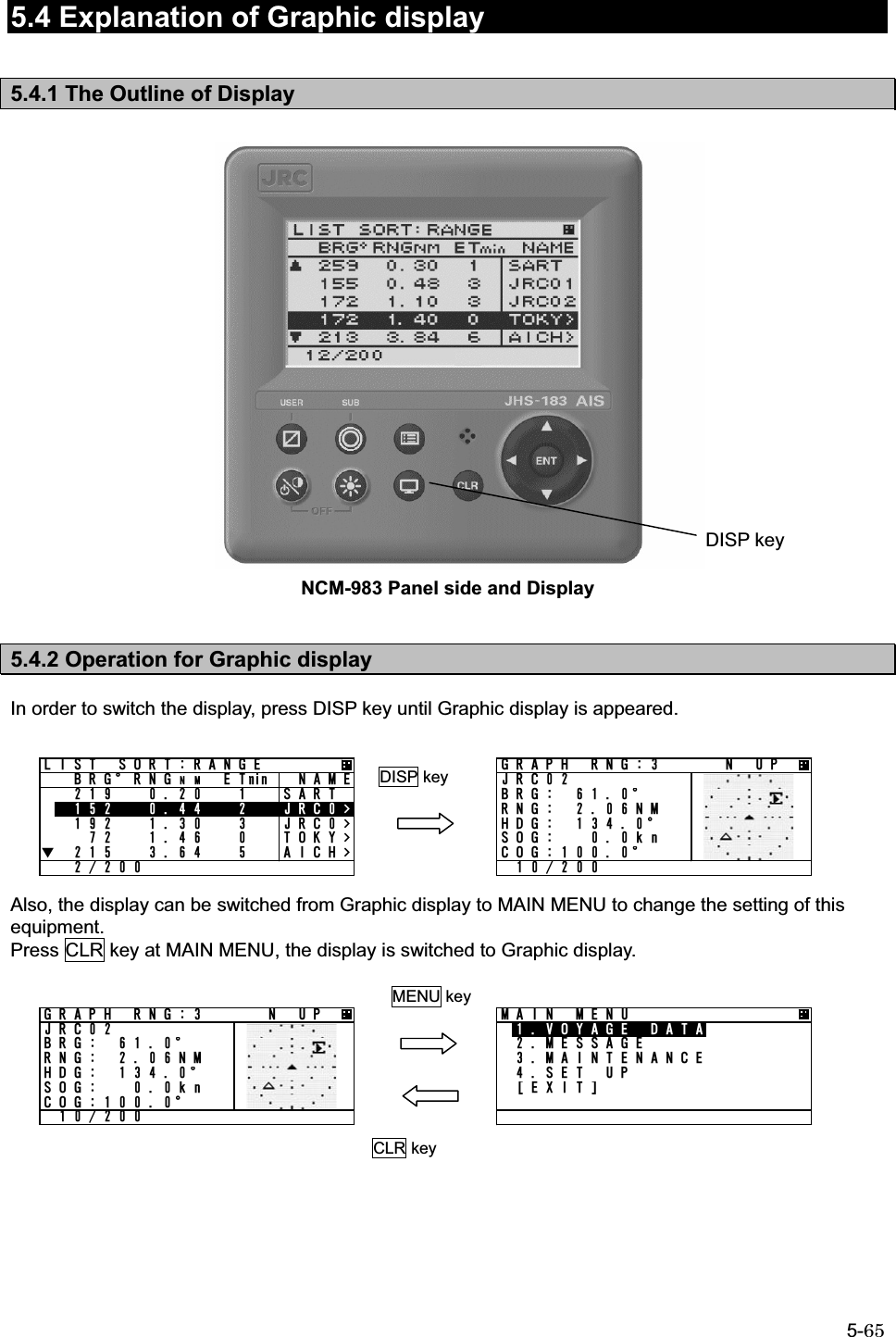
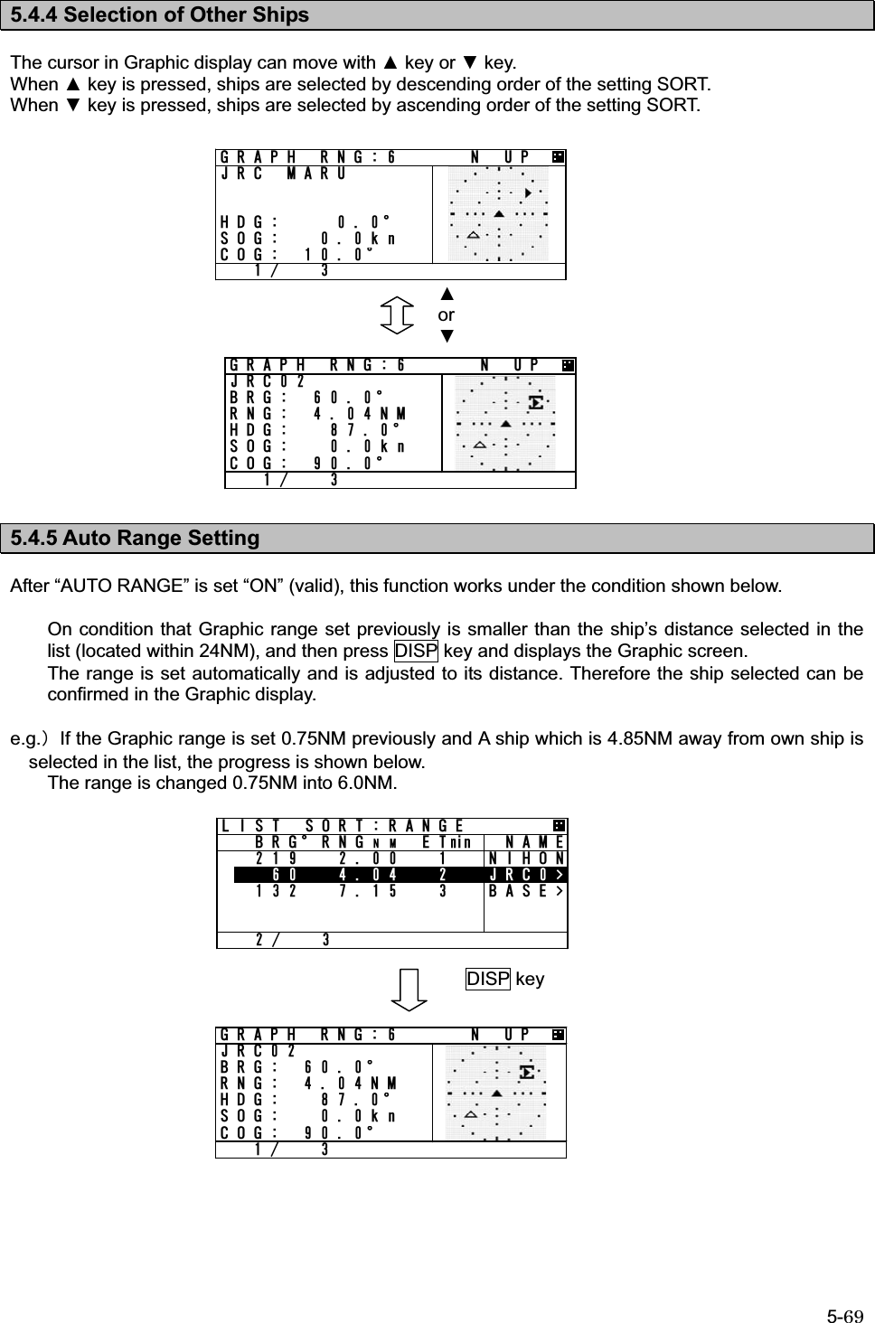
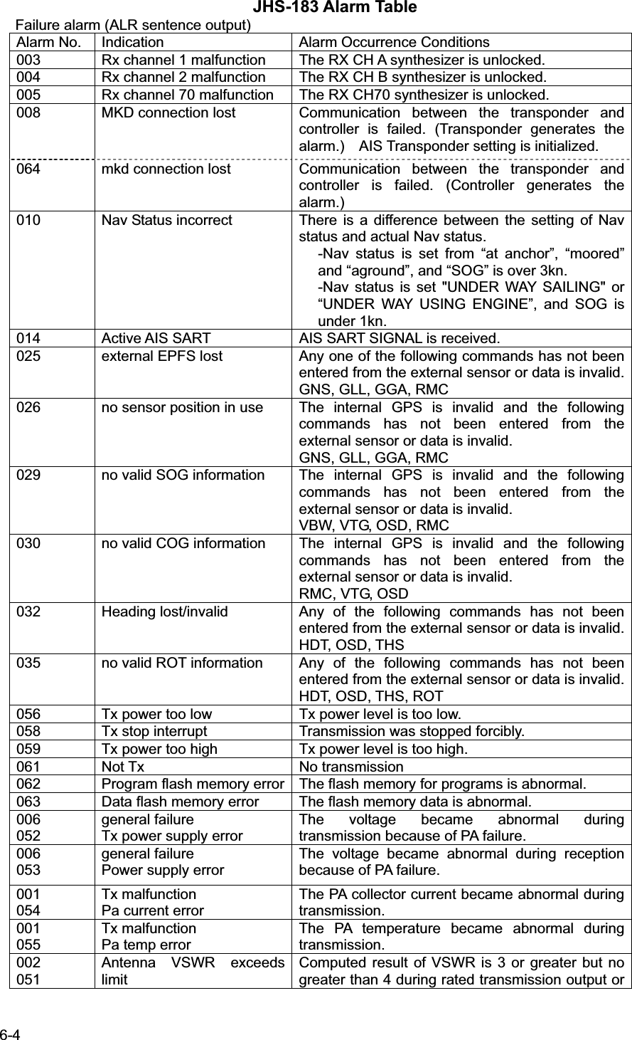
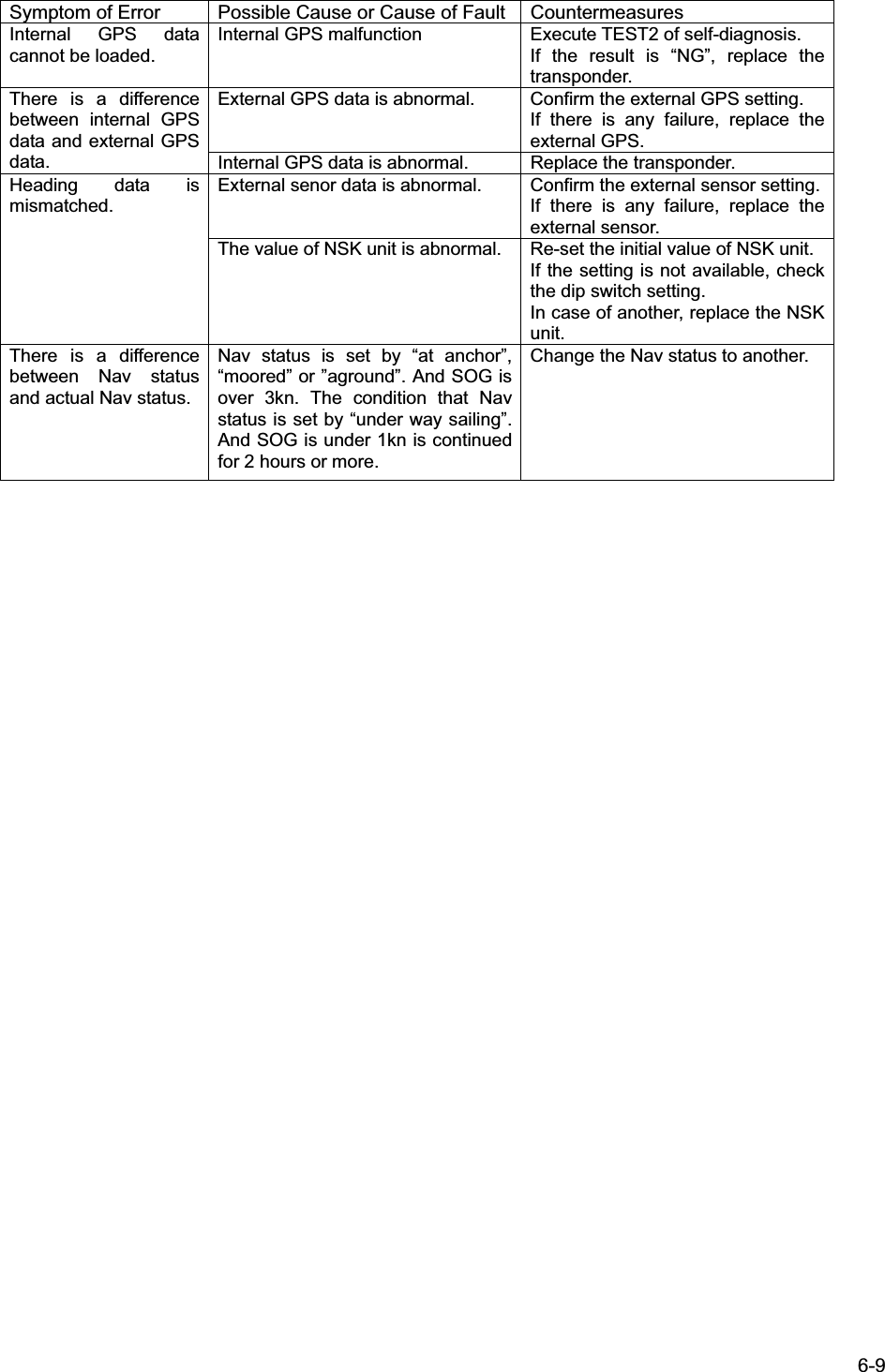
![5-66 5.4.3 Setting the Contents of Graphic Display Explain the setting of graphic display (e.g. range changes, setting of guard zone). 5.4.3.1 Display the Setting Screen Press SUB key at Graphic screen, and then switch to SUB MENU. In this SUB MENU, Select the desirable item with key or key and Press ENT key, then the item can be set. When [SET] is selected on page 2/3, the setting is saved. When [EXIT] is selected on page 3/3, the display switched to MAIN MENU. 5.4.3.2 Display Item Explanation 1. RANGE RANGE means the radius of external circle in the graphic screen. It is selected from 6 steps (0.75,1.5,3,6,12,24NM㧕with key or key. 2. BEARING North up of Head up can be select with key or key. North up 㧦Displays on a north basis Head up 㧦Displays on own ship’s heading basis. In case Heading value is not inputted (Not available), Only North up can be selected. 3. SORT SORT is selected from RANGE, TCPA and GROUP with key or key. RANGE 㧦In order of the distance from own ships and OTHER SHIPS LIST is arranged. TCPA 㧦In order of small TCPA from own ship and the list is arranged. GROUP 㧦In order of the distance and gives priority GROUP SHIP, and the list is arranged. SUB keySUB key or )4#2*+% &+52 5'657$ /'074#0)'0/$'#4+0)0146* 7251464#0)'0#/'5*+20#/'Ť)7#4& <10'0/)4#2*+% &+52 5'657$ /'07Ţ07/$'4 1( 5*+25%1064#56#761 4#0)'10Ť=5'6?)4#2*+% &+52 5'657$ /'07Ţ=':+6?)4#2* 40) 0 72,4%$4) c40) 0/*&) c51) MP%1) c](https://usermanual.wiki/Japan-Radio/JHS-183.User-Manual-2/User-Guide-1846410-Page-2.png)
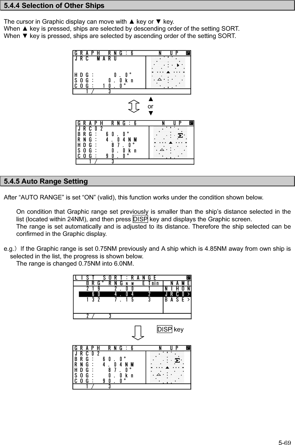
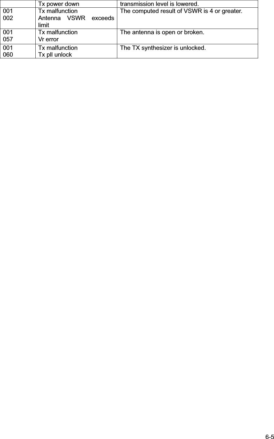
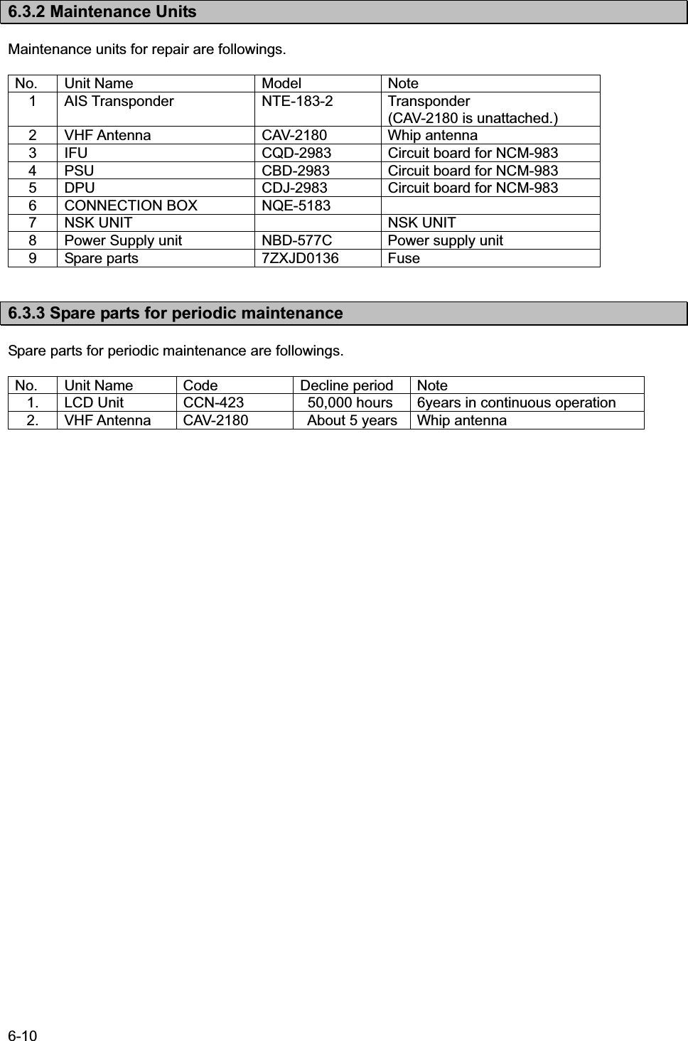
![5-68 5.4.3.3 Display Ԙ Heading㧦In 90-degree segment, 4 types are listed below. Value [degree] 314.5㧙 45.4 45.5㧙 134.4 134.5㧙 224.4 224.5㧙 314.4 Display 䂾䂾䂾䂾 ԙ ROT㧦3 types are listed below. Course + (right) 㧙 (left) 0 (straight) display 䂾䂾䂾 Ԛ Other marks Classification Mark Classification Mark Own ship 䂾 AIS SART 䂾 Other ships 䂾 Mark of route(Real) Aids to navigation 䂾 Base station 䂾 Mark of route (Virtual) 䂾 Cursor ԛ Display line Classification Mark Note Range circle Setting range Displayed by 15 degree interval circle. Guard zone alarm circle Setting range of guard zone Displayed by 30 degree interval circle ](https://usermanual.wiki/Japan-Radio/JHS-183.User-Manual-2/User-Guide-1846410-Page-4.png)