Japan Radio JHS-780D Marine VHF Radio Telephone User Manual 7ZPJD0406A JHS 770S 780D Instruction manual
Japan Radio Co Ltd. Marine VHF Radio Telephone 7ZPJD0406A JHS 770S 780D Instruction manual
UserManual.wiki
>
Japan Radio
>
JHS 780D User Manual
Instruction manual
Navigation menu
Upload a User Manual
Namespaces
Wiki Guide
HTML
PDF
Info
Views
User Manual
Discussion / Help
Navigation

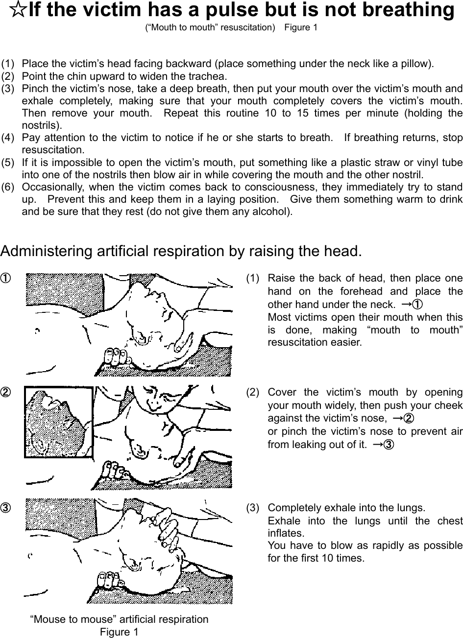
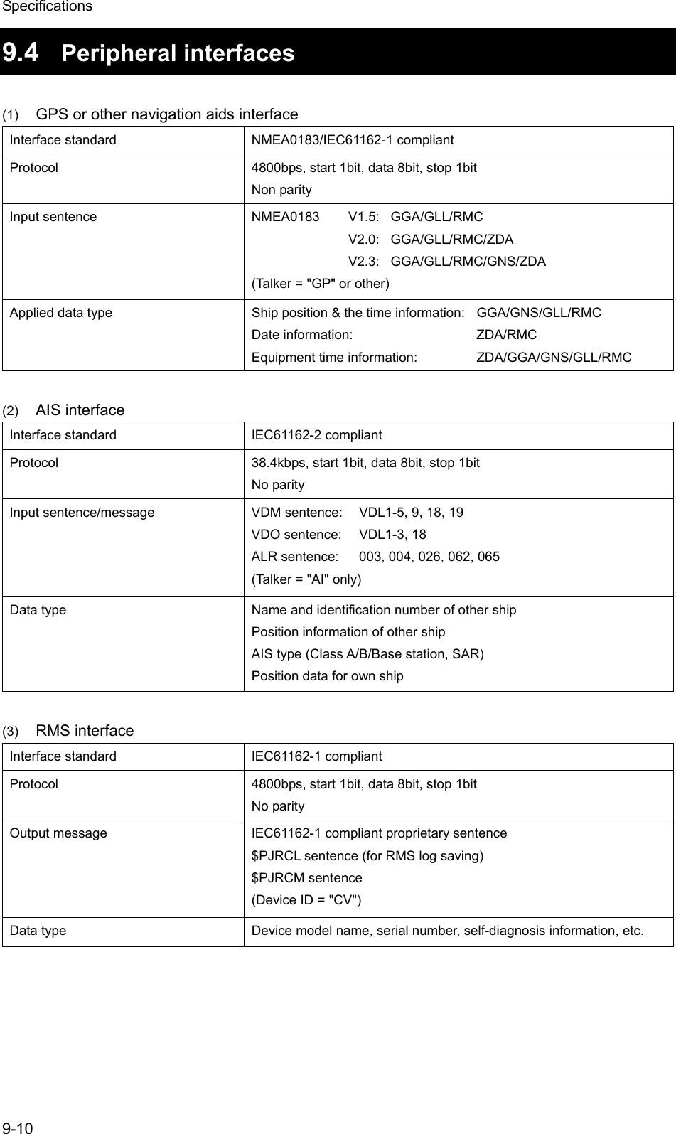
![v CAUTION To turn off an alarm or clear a display such as a received DSC message, do NOT press the DISTRESS key. Doing so may cause a false distress call. (Press the CANCEL key to turn off the alarm and delete the on screen message.) When sending a proxy distress call (DROBOSE), do NOT press the DISTRESS key. Doing so will inconvenience local shipping and Rescue Centers. (This proxy distress call can be sent via [Call] button displayed on the screen.) A distress acknowledgement or a distress relay call can be transmitted from a received distress message stored in the log, but when sending such a kind of call, follow the instructions of the ship's captain or officer in charge. In order to avoid accidental distress message treating, received distress messages will be erased automatically after 48 hours elapsed since the reception. Accordingly, if such messages cannot be read out, it is NOT a malfunction. The time in the menu 9.1.2 Present time is different from the time in the menu 9.2.2 UTC of position that means the time when the position information is valid. The time in the menu 9.2.2 UTC of position means the time when the position information is valid, and is different from the present time mentioned above. Close the water-resistant cap of the waterproof type handset box after use. Rain and sea breeze could cause connector malfunction. Also do not leave the handset above deck. The thermal head of the printer may be very hot after printing. Do not touch it. Perform paper replacement and head cleaning only after waiting for the head to completely cool. The printing paper used in this printer is a heat sensitive paper. Take the following precautions when using this paper. · Store the paper away from heat, humidity, or heat sources. · Do not rub the paper with any hard objects. · Do not place the paper near organic solvents. · Do not allow the paper to come in contact with polyvinyl chloride film, erasers, or adhesive tape for long periods of time. · Keep away the paper from freshly copied diazo type or wet process copy paper. For the CHANNEL SELECTOR (NCM-2000) installed above deck, close the water-resistant cap after use. Rain and sea breeze could cause connector malfunction. Also do not leave the handset above deck.](https://usermanual.wiki/Japan-Radio/JHS-780D/User-Guide-999383-Page-11.png)
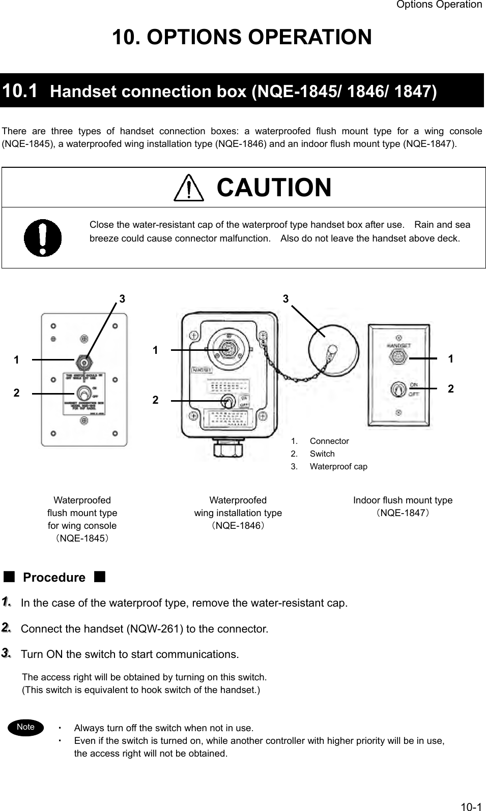
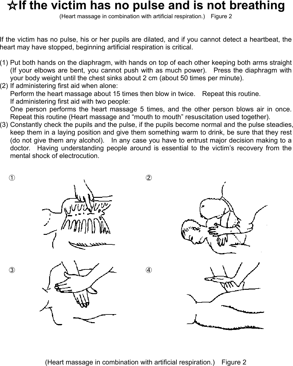
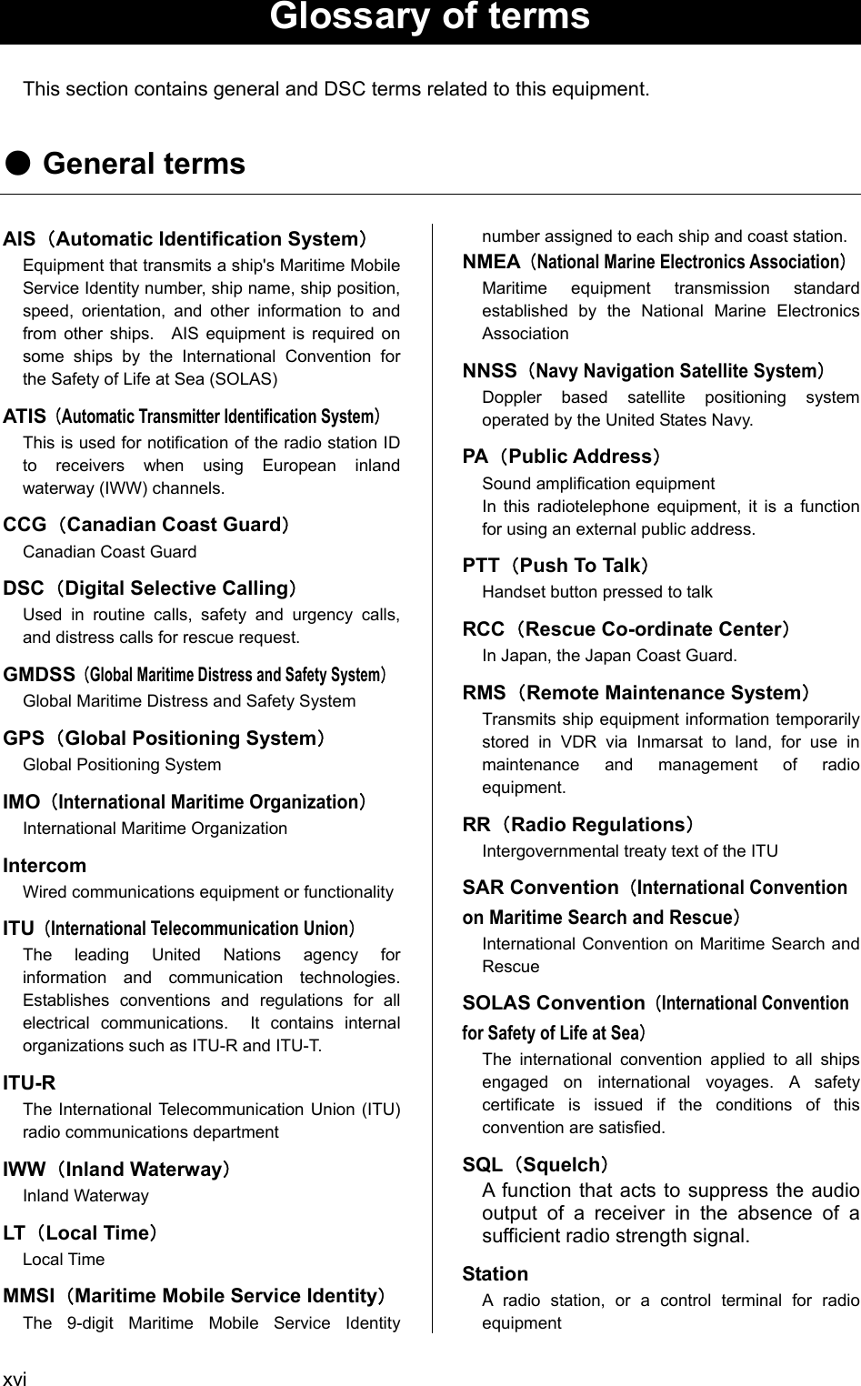
![vi Sending a Distress Call (Distress Alert) CAUTION When sending a distress call, follow the instructions of the ship's captain or officer in charge. 111... Open the DISTRESS key cover on the NCM-1770 CONTROLLER. 222... Press and hold the DISTRESS key for 4 seconds. (See the note below.) When completed the countdown and displayed the screen at right below, the distress call is transmitted. 333... After sending the distress call, wait for an acknowledgement. Radiotelephone can communicate even while waiting for an acknowledgement. When receiving a distress acknowledgement, the right screen is displayed. Unless received the distress acknowledgement or cancelled the distress call mode manually, this equipment repeats the distress call sending every 3.5 to 4.5 minutes automatically. 444... After receiving acknowledgement, lift the handset and request rescue using CH16 of the radiotelephone. First, the responding station calls by radiotelephone. Communicate the following information to that station. z Say "MAYDAY", z Say "This is (name of your ship)", z Tell the ship's Maritime Mobile Service Identity (MMSI) number, call sign, ship's position, nature of distress, and rescue requests DISTRESS CALLS Received Acknowledgement Type :Distress ACK... To :All ships ..... From :001234567...... Dist-ID :987654321...... Nature :Fire........... Position :34゚00.1234'N...Station1 TIME 23:59(UTC)16CH70 Press CANCEL to silence alarm.CH [ITU]](https://usermanual.wiki/Japan-Radio/JHS-780D/User-Guide-999383-Page-12.png)
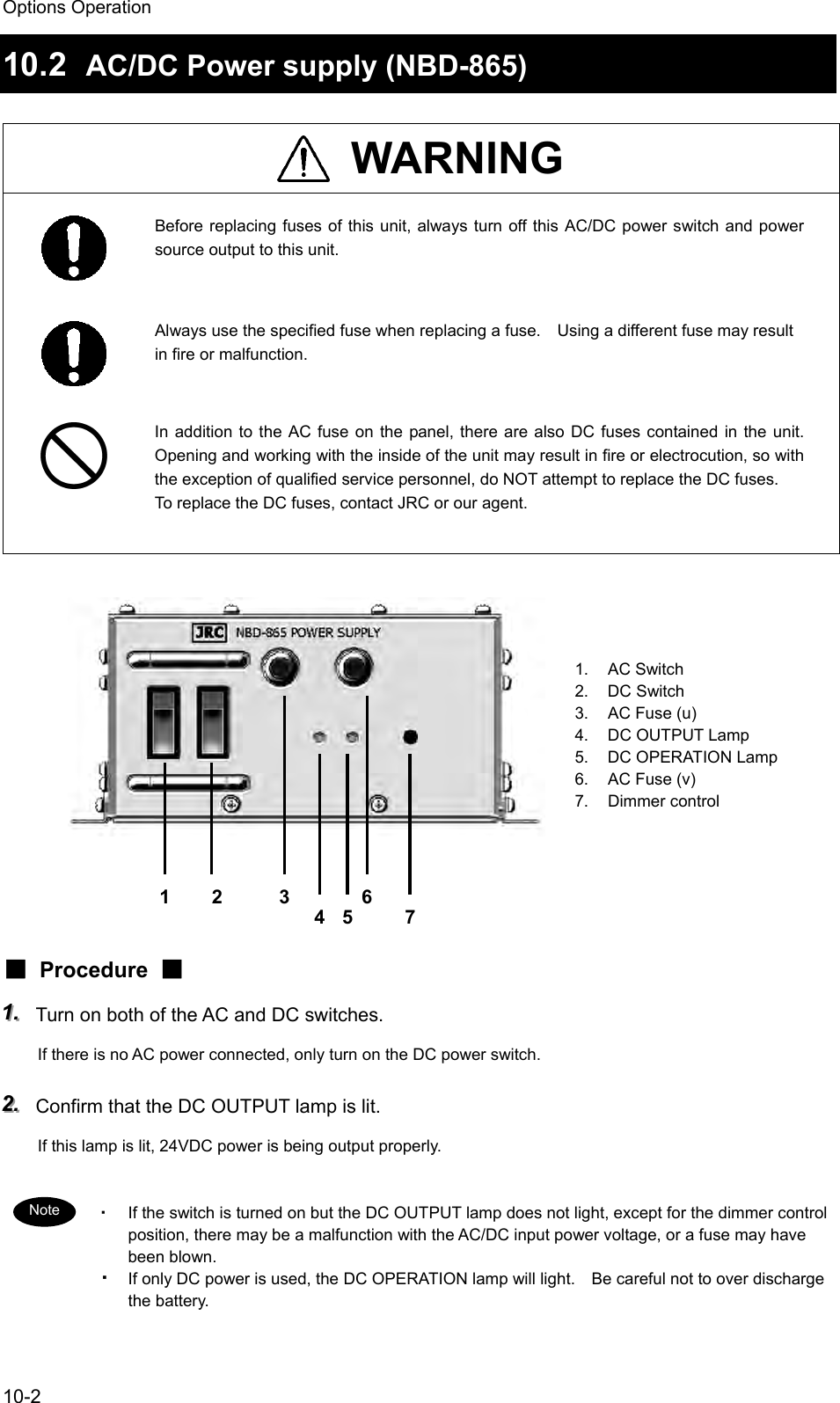
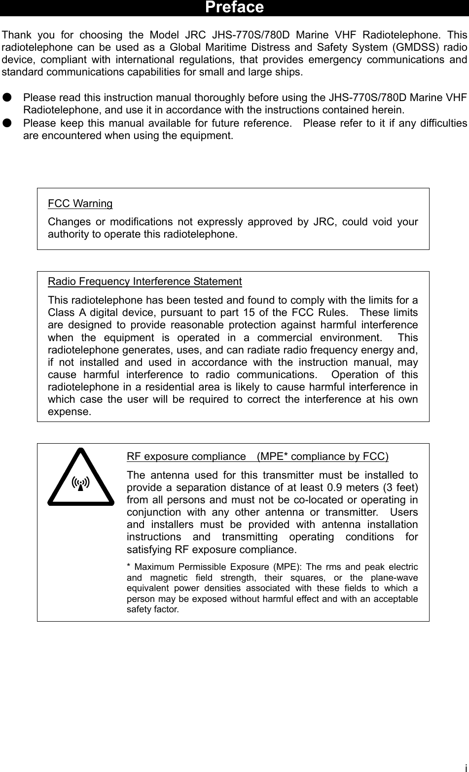
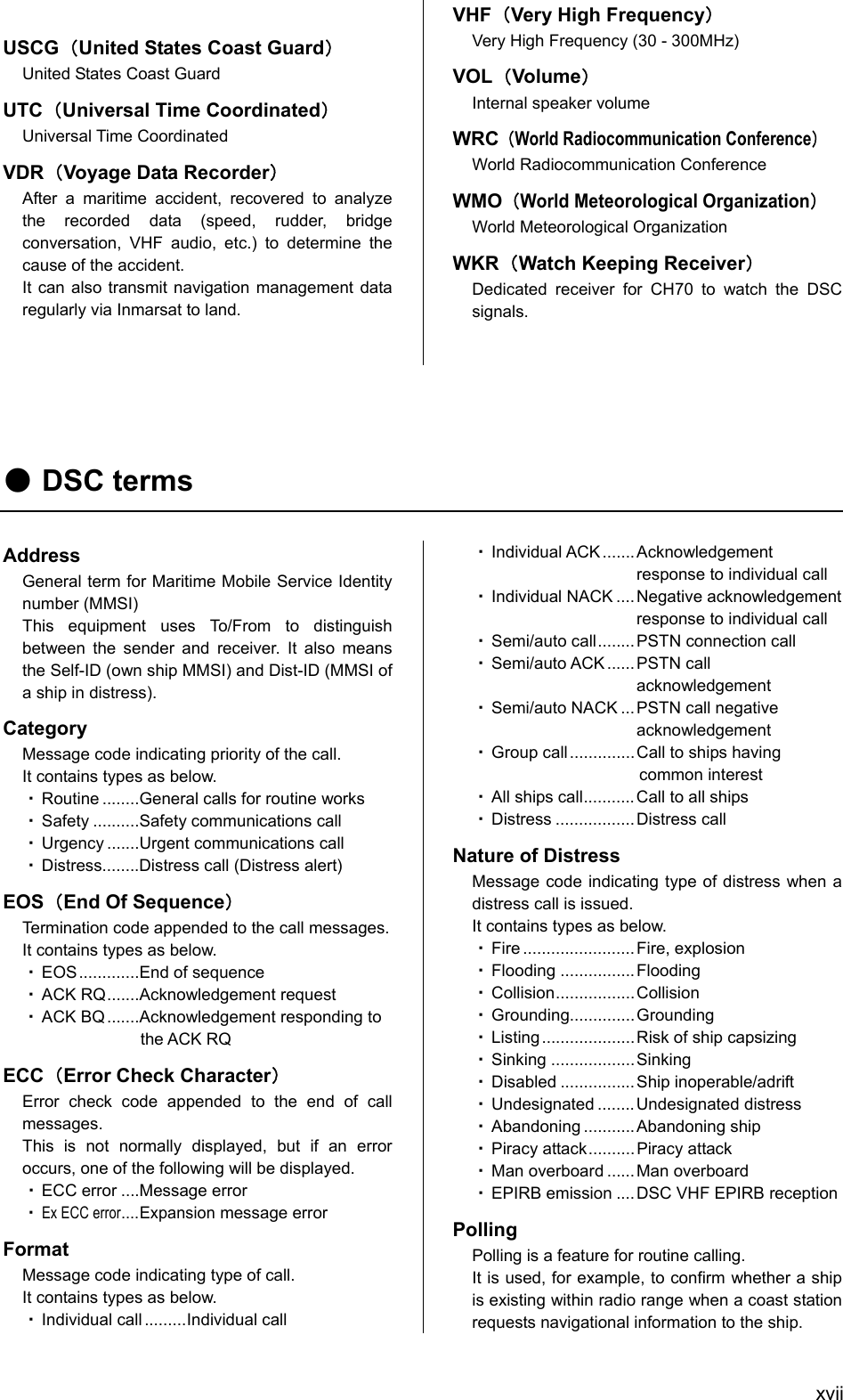
![vii If time permits, enter the nature of the distress as follows, just before the distress call. (For more details, see 4.4.3.2.) 1) Press the DISTRESS key momentarily to open the menu 2.3 Distress call. 2) Press ENT and select the nature of distress. 3) Press ENT to determine the selection. If not displayed the position and the time (UTC) automatically for any reason, input them manually at this time. 4) Press and hold the DISTRESS key for 4 seconds to send the distress call. The rest of the procedure is the same as described above. Terminating Transmission of a Distress Call CAUTION If a false distress call is transmitted accidentally, follow the instructions below: 1. Immediately terminate the distress call according to the following procedure. 2. Report the false distress call to a nearby RCC (Rescue Coordination Center). (In Japan, report to the Japan Coast Guard.) Information to be reported: The date/time, location, and reason why the false call was transmitted. Also report the ship's name, type, nationality, ID number as well as the unit model name and manufacture number/date, if possible. 3. Report the false distress call to nearby ships using CH16. 4. If any acknowledgements to the distress call are received, inform the ships of the false distress call. 111... Press the CANCEL key. If the CANCEL key is pressed during transmission of the distress call, immediately returns to the status display. If the CANCEL key is pressed in the interval between automatic resending of the distress call, the screen as shown below will be displayed. Select Break and press ENT with the jog dial to return to the status display. Note 2.3)Distress call Nature :[Undesignated ] Position:[NE] [ 12゚34.5678'S] [123゚45.6789'W] UTC :[12:20] Press DISTRESS to send. [Cancel]](https://usermanual.wiki/Japan-Radio/JHS-780D/User-Guide-999383-Page-13.png)
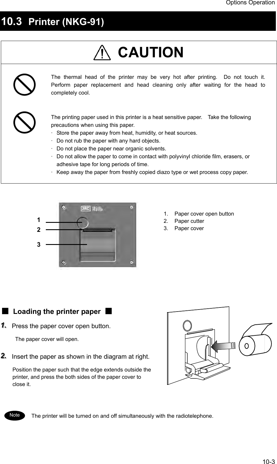
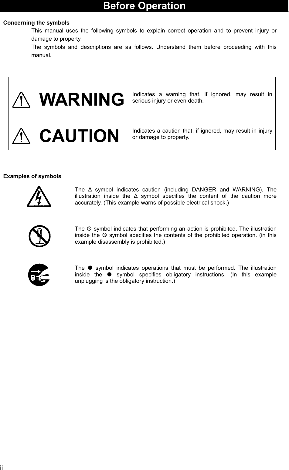
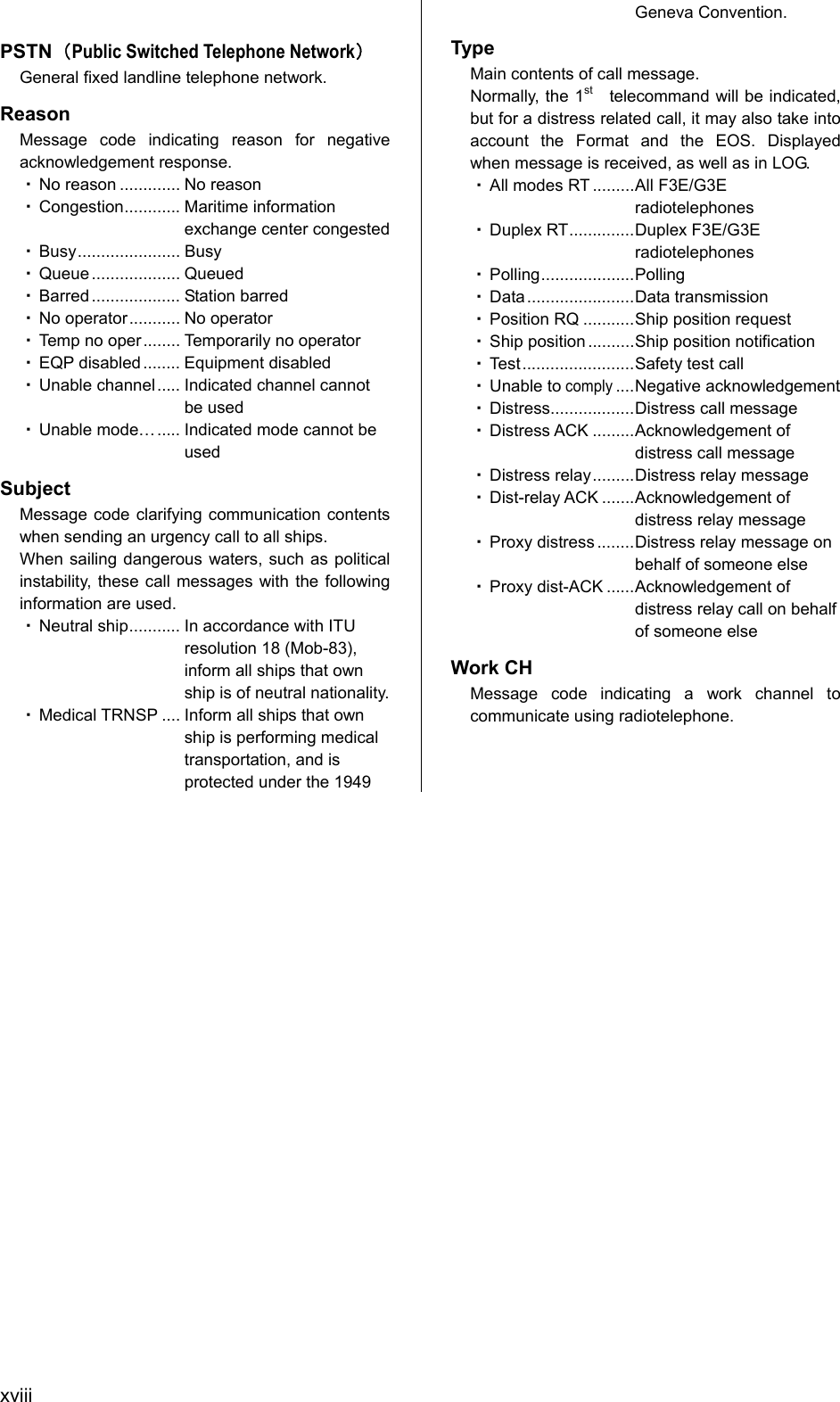
![viii Receiving a Distress Call WARNING If a distress call is received, make sure to inform the ship's captain or officer in charge. Doing so may save the lives of the crew and passengers on the ship in distress. 111... When a distress call is received, the message will be displayed. The ALM light will start blinking, and an alarm will sound growing louder gradually. 222... Press the CANCEL key to stop the alarm, and then press ENT and keep watch on CH16. Keep watch on CH16 for at least 5 minutes, and notify the coast station as appropriate. 333... When responding due to watching on CH16 and coordinating with the coast station, select the menu of 4.1 Received distress list and send the acknowledgement. After sending it, commence distress traffic via radiotelephony on CH16 as follows. z Say "MAYDAY", z Repeat the identity (MMSI) of the ship in distress 3 times, z Say "This is", z Repeat the identity (MMSI) of your ship 3 times, z Say "RECEIVED MAYDAY". Station1 TIME 23:59(UTC) POS 89゚59'S EXT 179゚59'W16CHSQLCH70CHSW[ITU] Received distress message Type :Distress....... From :431001234...... Nature :Fire........... Position :12゚34.5678'N... 123゚45.6789'E.. UTC :12:14..........Station1 TIME 23:59(UTC)16CH70 Press CANCEL to silence alarm.CH [ITU] Received distress message From :431001234...... Nature :Fire........... Position :12゚34.5678'N... 123゚45.6789'E.. UTC :12:14.......... EOS :EOSStation1 TIME 23:59(UTC)16CH70[OK/CH16 watch] [Cancel]CH [ITU]](https://usermanual.wiki/Japan-Radio/JHS-780D/User-Guide-999383-Page-14.png)
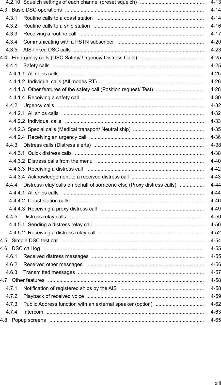

![Names and Functions 2-32.2 Main displays This section describes diligent displays such as the status display, menu screen, and DSC message receiving screen. 2.2.1 Status display 1. Occupied mark indicates when the other controller has the access rights. 2. Controller name. 3. Transmitting or PLL unlocking mark. z Transmitting.................... TX z PLL unlocking.................UNLOCK 4. Indicates the channel category as follows. z Priority channel, CH70 ....CH z Private channel ...............CH P0/1/2 z Other channel .................CH 5. On scanning, indicates the current condition. z.... Scanning.................... z.... Dual Watch ................ 6. Indicates the region type of a current channel. z [ITU]....ITU channel z [USA]....USA channel z [CAN]....Canada channel z [IWW]....European inland waterway channel 7. Indicates the squelch status as follows. z Closed............................. SQL z Opened ........................... SQL z Closed by Preset SQL .... p SQL z Opened by Preset SQL... p SQL Also, the actual squelch level is shown on this level indicator 8. Indicates CH70 watching continuously by the DSC watchkeeping receiver. 9. Indicates that the DSC is in the automatic acknowledgement mode. 10. Indicates that the DSC is NOT in the automatic channel shift mode. 11. Indicates the source of the ship’s position information as follows. z External device (e.g. GPS) ..........EXT z Manual input................................MAN 12. Indicates current time as follows: z Universal time coordinated ......... UTC z Local time ................................... LT 13. Indicates own ship’s position. 14. Indicates current channel. 15. Indicates if currently selected a duplex channel to communicate with a coast station. 16. Indicates Tx power is set to 1W. 17. Indicates the built-in loud speaker's ON/OFF. Note that in the case of using a duplex channel for the JHS-780D, when taking a handset off-hook, the loud speaker will be OFF automatically. 18. VSWR alarm mark. Indicates when detected a bad VSWR at transmission. 16&SCAN16&11 13 14 16 17 9 108 6 5 4 3 2 1 12 7 15 Station1 TIME 23:59(UTC) POS 89゚59'S EXT 179゚59'W88CH[ITU]TXOCCSQLCH70CHSWSCAN16&VSWR18](https://usermanual.wiki/Japan-Radio/JHS-780D/User-Guide-999383-Page-41.png)
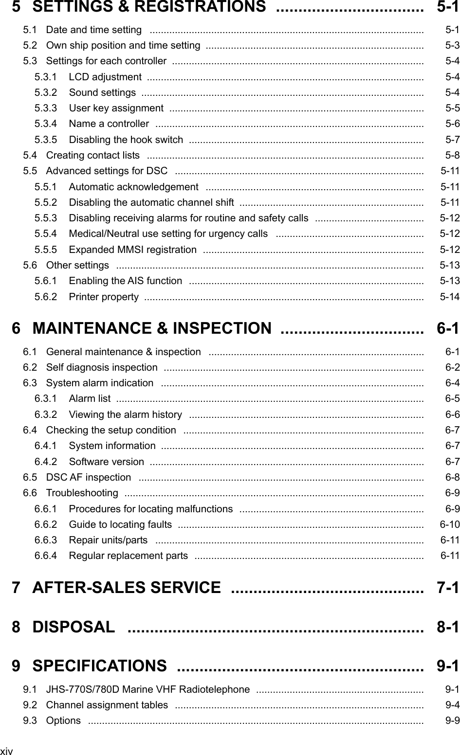
![Names and Functions 2-4 2.2.2 Menu screen 1. Indicates if opened the squelch while performing one of the 6. Voice function menus. 2. Transmitting mark. 3. Indicates the current menu name. 4. Indicates the menu content. The cursor line or position is highlighted. 5. Indicates that the menu content is continued below. 6. Indicates the main radiotelephone information as with the status display. Main menu 1.DSC routine call 2.DSC emergency call 3.DSC test call 4.DSC logs 5.AIS information 6.Voice function 7.Channel operationStation1 TIME 23:59(UTC)OCCDW18CH70161.DSC routine callDUPTXRXVSWRCH [ITU] 6 3 5 4 2 1](https://usermanual.wiki/Japan-Radio/JHS-780D/User-Guide-999383-Page-42.png)
![Names and Functions 2-5 2.2.3 DSC message receiving screen 1. Indicates the received message category. (Routine, Safety, Urgency, Distress) 2. Indicates the received message. The example above shows the following contents. ¾ Format : Individual call to own ship ¾ From : The caller's MMSI is 123456789. ¾ Type : Radiotelephone is proposed as a subsequent communication type. ¾ Work CH : CH18 proposed as a work channel. ¾ EOS : Requested the acknowledgement. 3. Indicates message handling menu for received message. The example above shows the following. z [OK/Lift handset] Agreed to the call, and start radiotelephone communications immediately. z [New CH] Agreed to the call except the proposed channel, and reply to the call with a new channel proposal. z [Unable/NACK] Not agreed to the call, and reply to the call as "unable to comply" with a reason. z [Cancel] Returns to the status display without replying. ・ When selecting [OK/Lift handset] , just lifting a handset enables to start communications without selecting this item by the jog dial. ・ When selecting [New CH] or [Unable/NACK], an editing screen will appear. Received routine message Format :Individual call From :123456789...... Type :All modes RT... Work CH :18............. EOS :ACK RQ.........Station1 TIME 23:59(UTC)16CH70 [OK/Lift handset] [New CH] [Unable/NACK] [Cancel][OK/Lift handset]CH [ITU]1 2 3 Note](https://usermanual.wiki/Japan-Radio/JHS-780D/User-Guide-999383-Page-43.png)
![Operation 4-3 4.2 Basic communication procedure The following describes basic radio communication procedures. 4.2.1 Turning ON the power CAUTION Do NOT turn off the power of the equipment when at sea because the SOLAS Convention requires keeping CH16 watch at all times. ■ Procedure ■ 111... Press the key for one second. The controller and transceiver will start the internal check. After finished it correctly, the status display will appears. (The screen at right shows the case of the JHS-770S Model.) - When the controller is turned on from sleep mode, the status display will be displayed immediately without cheking the memory. - If detected errors during the memory check, displays the message below. Please inform JRC or our agent of the error contents. Message Contents Detected memory error! So cleared the area of transceiver memory. Detected a memory error when starting the transceiver.Detected memory error! So cleared the area of controller memory. Detected a memory error when starting controller. Detected this controller's address setting error! So required initial set after restarting as the maintenance mode Detected this controller's address error when starting the controller. Detected SIO error! So required initial set after restarting as the maintenance mode. Detected a serial error when starting controller. Detected MMSI lost! So concerned functions (DSC/ATIS) no longer available now. Unregistered MMSI yet, or lost the MMSI. So required to install MMSI for DSC/ATIS. Detected the transceiver's PCB combination error! So required to replace that incorrect PCB with the correct one. Detected the improper transceiver's PCB combination.PWRCONTNote Station1 TIME 23:59(UTC) POS 89゚59'S EXT 179゚59'W16CHSQLCH70CHSW[ITU] JHS-770S VHF Radiotelephone [Self-ID: 987654321] Controller Version:1.00 Transceiver Version:1.00 JHS-770S VHF Radiotelephone [Self-ID: 987654321] Controller Version:1.00 Transceiver Version:1.00](https://usermanual.wiki/Japan-Radio/JHS-780D/User-Guide-999383-Page-47.png)
![Operation 4-4 4.2.2 Turning OFF the power ■ Procedure ■ 111... Press the key and the DIM key simultaneously. After that, the power-off process is activated according to the controllers' situation. When using only one controller Select the desired item below on the displayed popup screen at right. ・ [OK]: Turns off the power. ・ [Cancel]: Returns to the previous screen. When using two or more controllers Select the desired item below on the displayed popup screen at right. ・ [OK]: Turns off the power. ・ [Sleep]: Sets the controller to sleep mode. ・ [Cancel]: Returns to the previous screen. In sleep mode, the controller becomes the following conditions. ・ Only the controller is powered off. ・ The ALM lamp turns green to indicate that the controller is in sleep mode, ・ When receiving a distress call, the controller will be automatically turned on and activate the alarm if the Wake-up setting in an installation menu is ON,. ・ Even if set the controller with access right to the sleep mode, the access right will not move from the controller. Note PWR CONT](https://usermanual.wiki/Japan-Radio/JHS-780D/User-Guide-999383-Page-48.png)
![Operation 4-7 4.2.4 Receiving with scanning Scanning function enables to watch multiple channels (additional channels) with the priority channel (CH16). If found receiving signal on the additional channels, the dwell time on that channel will be longer, but continued to watch the CH16 alternatively. The scan mode can be selected from the following modes. ・ All CH scan Mode: Scans all channels in the current channel mode. ・ Memory CH scan Mode: Scans all memory channels. ・ Select CH scan Mode: Scans the specified range of channels. ■ Procedure ■ 111... Press FUNC Î 2SCAN . The menu will be displayed as shown at right. 222... Move the cursor to the desired item and press ENT using the jog dial, or press the item number by a numeric key directly. ¾ If selected "1. All CH scan" or "2. Memory CH scan", scanning starts immediately. ¾ If selected "3. Select CH scan", specify the channel range as described below. 1) To set the start channel (From): Press ENT and after entering the channel number, press ENT again. 2) To set the stop channel (To): Press ENT and after entering the channel number, press ENT again. 3) To start the scanning: Select Execute and press ENT. Then starts the scanning as shown at right. - Disabled to scan when the channel region is Inland Waterways (IWW). - CH70 will be skipped, even if contained in the scanning range. 333... To terminate scanning, press the CANCEL key. ¾ After terminated, the radiotelephone will be set on the last additional channel. (The example at right shows when stopped on CH12.) ¾ Scanning will be also terminated when detected off-hook, PTT ON, or press the CH16 key or the DISTRESS key. - While scanning, the radiotelephone scans CH16 and the additional channels alternatively in a cycle of 0.14/0.86 seconds. - If the squelch is opened on the CH16, paused scanning and continues to watch on 7.1)Scan 1.All CH scan 2.Memory CH scan 3.Select CH scan (ITU) - From : CH - To : CH - Execute 0.Back Note 7.1)Scan 1.All CH scan 2.Memory CH scan 3.Select CH scan (ITU) - From : CH - To : CH - Execute 0.Back Note Station1 TIME 23:59(UTC) POS 89゚59'S EXT 179゚59'W10CHCH70CHSWSCAN16&[ITU]SQLStation1 TIME 23:59(UTC) POS 89゚59'S EXT 179゚59'W12CHCH70[ITU]SQLCHSW](https://usermanual.wiki/Japan-Radio/JHS-780D/User-Guide-999383-Page-51.png)
![Operation 4-8 the CH16. If squelch is closed again, the scanning will resume 2 seconds later. - If the squelch is opened on an additional channel, remains on that channel and CH16 alternatively (in a cycle of 0.14/1.86 seconds). If squelch is then continuously closed (until the end of the scan cycle), the scanning will resume. Furthermore, added to the additional channel, if the squelch is also opened on the CH16, paused scanning and continues to watch on the CH16 as described above. 4.2.5 Receiving with dual watch Dual watch function enables to watch an additional channel with the priority channel (CH16). If found receiving signal on the additional channel, the dwell time on that channel will be longer, but continued to watch the CH16 alternatively. ■ Procedure ■ 111... Select an additional channel to be watched with CH16. The example at right shows the case of CH10 selected. 222... Press FUNC Î 1DW The dual watch will start immediately. Disabled the dual watch either when the channel region is Inland waterways (IWW) or when CH70 has been selected. 333... To terminate the dual watch, press the CANCEL key. ¾ After terminated, the radiotelephone will be set on the additional channel. (The example at right shows when stopped on CH10.) ¾ The dual watch will be also terminated when detected off-hook, PTT ON, or press the CH16 key or the DISTRESS key. - During the dual watch, the radiotelephone watches CH16 and the additional channel alternatively in a cycle of 0.14/0.86 seconds. - If the squelch is opened on the CH16, pauses the dual watch and continues to watch on the CH16. If squelch is closed again, the dual watch will resume 2 seconds later. - If the squelch is opened on the additional channel, the dwell time on that channel will be longer, but continues to watch the CH16 alternatively (in a cycle of 0.14/1.86 seconds). If squelch is then continuously closed (until the end of the dwell time), the dual watch will resume. Furthermore, added to the additional channel, if the squelch is also opened on the CH16, pauses the dual watch and continues to watch on the CH16 as described above. - This function is also available from the menu 7.2 Dual watch. Note Note Station1 TIME 23:59(UTC) POS 89゚59'S EXT 179゚59'W10CHCH70[ITU]SQLCHSWStation1 TIME 23:59(UTC) POS 89゚59'S EXT 179゚59'W10CHCH70[ITU]SQLCHSWStation1 TIME 23:59(UTC) POS 89゚59'S EXT 179゚59'W10CHCH7016&[ITU]SQLCHSW](https://usermanual.wiki/Japan-Radio/JHS-780D/User-Guide-999383-Page-52.png)
![Operation 4-12 4.2.9 Changing the channel region This menu sets the channel region to ITU, USA, Canada, or Inland Waterway. ■ Procedure ■ 111... Press the MENU key, and through hierarchical menus, select the 7.6 Region. 222... Move the cursor to the desired line and press ENT using the jog dial, or press a numeric key directly. When selected the USA channel, the screen will become as shown at right. When set to the Inland Waterway (IWW), changed a few functions as follows. - Enabled the ATIS function automatically and sends the ATIS code over the voice channel when releasing the PTT key. Also, if pressed the PTT key continuously, sends the ATIS code every five minutes automatically. - Disabled the scan or dual watch functions. - When operating the DSC menus, a popup screen will be displayed to notice that the DSC usage is not allowed on Inland Waterways. 7.6)Region 1.ITU channel [ITU] 2.USA channel [USA] 3.Canada channel [CAN] 4.Inland channel [IWW] 0.Back Note Station1 TIME 23:59(UTC) POS 89゚59'S EXT 179゚59'WCHCH7016[USA]SQLCHSW](https://usermanual.wiki/Japan-Radio/JHS-780D/User-Guide-999383-Page-56.png)
![Operation 4-13 4.2.10 Squelch settings of each channel (preset squelch) The adjusted squelch value can be stored with respect to each channel as a preset squelch. The handling of the preset squelch will be as follows. ・ If stored the squelch value, the preset squelch will be always set just after the channel selection. ・ While the preset squelch has been set, "p SQL" will be indicated on the status display. ・ If turned the SQL control after setting the preset channel, the preset value will be canceled immediately and the SQL control will be available. ・ The preset squelch value can be cleared with respect to each channel or each channel region. ■ Procedure ■ 111... After selecting the desired channel, press the MENU key and through hierarchical menus, select the 7.7 CH SQL setting. 222... Turn the SQL control to the appropriate position. The SQL value as shown at right will be changed corresponding to the SQL control position. 333... Press ENT. The cursor will move to the right. 444... To complete the squelch setting for the channel, select "Set" and press ENT. - To clear the preset squelch values with respect to each channel, after selecting the channel, select Erase and press ENT at the step 3 above. - To clear the preset squelch values with respect to each channel region, in the condition of that channel region, move the cursor to the 2. All clear and press ENT. - The above operation is also available on a popup menu displayed when pressed both of the FUNC key and the CANCEL key simultaneously on the status display. 7.7)CH SQL setting SQL value [052] 1.Preset : Set 2.All clear 0.Back 7.7)CH SQL setting SQL value [041] 1.Preset : Set 2.All clear 0.Back 7.7)CH SQL setting SQL value [025] 1.Preset : Set 2.All clear 0.Back 7.7)CH SQL setting SQL value [025] 1.Preset : Set 2.All clear 0.Back Note](https://usermanual.wiki/Japan-Radio/JHS-780D/User-Guide-999383-Page-57.png)
![Operation 4-14 4.3 Basic DSC operations When calling stations, the DSC is also available for a routine/ safety/ urgency or a distress call in addition to the calling by radiotelephone described above. This section describes the procedures for basic DSC routine calls and for the AIS-linked DSC calls. 4.3.1 Routine calls to a coast station A DSC call to a coast station is initiated as follows. ■ Procedure ■ 111... Press the MENU key, and through hierarchical menus, select the 1.1 Coast station call. The address inputting screen will be displayed. If entered previously, the address will be appeared as a default value. 222... Press ENT to display the alphabetically sorted coast station list. After selecting the initial letter and pressing ENT, select the desired coast station with the jog dial. - This list can be registered in the menu 9.4.1 Coast station list. - When inputting the MMSI manually, press the CANCEL key to return to the previous screen and input it using the numeric keypad. 333... After inputting the address, press ENT. Confirm the address. 444... If the address is correct, press ENT. The sending confirmation screen will appear. The controller displays by default only the edited information in the call setup as shown at right. 1.1)Coast station call Address :[00 ] [ OK ] [Cancel] 1.1)Coast station call Address :[001234567] [ OK ] [Cancel] 1.1)Coast station call Address :001234567 [Call] [Cancel] Note Note Coast station list [A] NAME MMSI Argentina Australia Azerbaijan Bolivia Bangladesh 001234567 002222222 003333333 004444444 005555555 Select the initial of the name. ABCDEFGHIJKLMNOPQRSTUVWXYZ](https://usermanual.wiki/Japan-Radio/JHS-780D/User-Guide-999383-Page-58.png)
![Operation 4-15 555... Press ENT to transmit the call. After completed the transmission, the popup screen shown at right will be displayed to wait the acknowledgement. If received no response for 5 minutes, the screen will return to the step 3 mentioned above. 666... When received the acknowledgement, the screen shows the message with the alarm for 3 sec. Then changes to the working channel proposed by the coast station automatically. - If 9.5.2 Automatic CH shift is OFF, lifting the handset or pressing ENT is required to set the proposed working channel. - If an improper channel is proposed, resend the call containing a new channel via the specified new channel proposal form screen. 777... The coast station call will be completed after displayed the working channel as shown at right. Start communications using the handset. ¾ The example at right shows when proposed CH12 as a working channel. ¾ When completed the communications, return the handset to the cradle. If the coast station is unable to comply with the call, own station (caller) may receive one of the following responses may be received. In these cases, if possible according to the message, wait and retry the calling again later. Message Content No reason No reason. Congestion The marine exchange center is congested.Busy Busy. Queue The call has been queued. Barred The station is closed. No operator Existing no operator. Temp no oper The operator is temporarily away. EQP disabled The equipment has been disabled. Unable channel The proposed channel cannot be used. Unable mode The proposed mode cannot be used. Note 1.1)Coast station call Address :[001234567] [Call] [Cancel] Waiting for Acknowledgement. [Cancel] Note Note Station1 TIME 23:59(UTC) POS 89゚59'S EXT 179゚59'W12CHCH70[ITU]SQLCHSW Received routine message Format :Individual ACK From :001234567...... Type :All modes RT... Work CH :12............. EOS :ACK BQ.........Station1 TIME 23:59(UTC)16CH70 Press CANCEL to silence alarm.CH [ITU]](https://usermanual.wiki/Japan-Radio/JHS-780D/User-Guide-999383-Page-59.png)
![Operation 4-16 4.3.2 Routine calls to a ship station A DSC call to a ship station is initiated as follows. This procedure is similar to that of menu 1.1 Coast station call but also needed to input a working channel. ■ Procedure ■ 111... Press the key. The menu shown at right will be displayed. If entered previously, the address will be appeared as a default value. 222... Press ENT to display the alphabetically sorted ship station list. After selecting the initial letter and pressing ENT, select the desired ship station with the jog dial. - The list can be registered in the menu 9.4.2 Ship station list. - When inputting the MMSI manually, press the CANCEL key to return to the previous screen and input it using the numeric keypad. 333... Press ENT. The cursor will move to the Work CH. 444... Press ENT and input the working channel. - The free channel will be searched and displayed automatically. - If required, input another channel manually using the CANCEL key, the jog dial or the numeric keys. - If there is no free channel, a blank will be shown as a search result. 555... Press ENT. Confirm the entered contents. 1.2)Ship station call Address :[ ] Work CH :[ ] [ OK ] [Cancel] 1.2)Ship station call Address :[123456789] Work CH :[ ] [ OK ] [Cancel] 1.2)Ship station call Address :[123456789] Work CH :[06] [ OK ] [Cancel] Note 1.2)Ship station call Address :[123456789] Work CH :[06] [ OK ] [Cancel] DSC RTN Ship station list [A] NAME MMSI AAA ocean ABB ocean ACC ocean ABC ocean BBB ocean 123456789 222222222 333333333 444444444 555555555 Select the initial of the name. ABCDEFGHIJKLMNOPQRSTUVWXYZ Note](https://usermanual.wiki/Japan-Radio/JHS-780D/User-Guide-999383-Page-60.png)
![Operation 4-17 666... If the contents are correct, press ENT. The sending confirmation screen will appear. The controller displays by default only the edited information in the call setup as shown at right. 777... Press ENT to transmit the call. After completed the transmission, the popup screen shown at right will be displayed to wait the acknowledgement. If received no response for 5 minutes, the screen will return to the step 5 mentioned above. 888... When received the acknowledgement, the screen shows the message with the alarm for 3 sec. Then changes to the proposed working channel automatically. - If 9.5.2 Automatic CH shift is OFF, lifting the handset or pressing ENT is required to set the proposed working channel. - If an improper channel is proposed, resend the call containing a new channel via the specified new channel proposal form screen. 999... The ship station call will be completed after displayed the working channel as shown at right. Start communications using the handset. ¾ The example at right shows when proposed CH06 as a working channel. ¾ When completed the communications, return the handset to the cradle. - If the ship station is unable to comply with the call, as with coast stations, own station (caller) may receive a negative acknowledgement mentioned above section. In this case, if possible according to the message, wait and retry the calling again later. - When calling group ships to broadcast, use the menu 1.4 Group call as with this procedure except for steps 7 and 8. Note 1.2)Ship station call Address :123456789 Work CH :06 [Call] [Cancel]Note 1.2)Ship station call Address :123456789 Work CH :71 [Call] [Cancel] Waiting for Acknowledgement. [Cancel] Note Note Station1 TIME 23:59(UTC) POS 89゚59'S EXT 179゚59'W06CHCH70[ITU]SQLCHSW Received routine message Format :Individual ACK From :123456789...... Type :All modes RT... Work CH :06............. EOS :ACK BQ.........Station1 TIME 23:59(UTC)16CH70 Press CANCEL to silence alarm.CH [ITU]](https://usermanual.wiki/Japan-Radio/JHS-780D/User-Guide-999383-Page-61.png)
![Operation 4-18 4.3.3 Receiving a routine call When receiving a DSC call from a coast or ship station, the message will be displayed immediately on the screen. After that, perform the following procedures as appropriate. (1) Receiving an individual call (type: radiotelephone) ■ Procedure ■ 111... The screen at right will be displayed, and the alarm will sound. This example message contains the following information. - Format: Individual call - Caller's MMSI: 111222333 - Type: All modes radiotelephone - Work channel: CH12 - EOS: ACK is requested. 222... Press the CANCEL key to stop the alarm and display the screen at right. This step is omissible. 333... If possible to communicate immediately, lift the handset from the cradle and start the communications. ¾ In this example case, enabled to select the response from below with the jog dial. ・OK/Lift handset: Starts communications immediately. ・New CH: Proposes a new channel. ・Unable/NACK: Sends "Unable to comply" message with that reason. ・Cancel: Returns to the status display without handling this message. ¾ When completed the communications, return the handset to the cradle. When selected "Unable/NACK", also select a reason from the list given below. Message Content No reason No reason. Busy Busy. Barred The station is closed. No operator Existing no operator. Temp no oper The operator is temporarily away. EQP disabled The equipment has been disabled. Unable channel The proposed channel cannot be used. Unable mode The proposed mode cannot be used. Received routine message Format :Individual call From :111222333 Type :All modes RT Work CH :12 EOS :ACK RQ [OK/Lift handset] [New CH] [Unable/NACK] [Cancel] Received routine message Format :Individual call From :111222333 Type :All modes RT Work CH :12 EOS :ACK RQ Press CANCEL to silence alarm. Note Note Station1 TIME 23:59(UTC) POS 89゚59'S EXT 179゚59'W12CHCH70[ITU]SQLCHSW](https://usermanual.wiki/Japan-Radio/JHS-780D/User-Guide-999383-Page-62.png)
![Operation 4-19 (2) Receiving an individual call (type: polling) ■ Procedure ■ 111... The screen at right will be displayed, and the alarm will sound. This example message contains the following information. - Format: Individual call - Caller’s MMSI: 001234567 - Type: Polling - EOS: ACK is requested. 222... Press the CANCEL key to stop the alarm and display the screen at right. If possible to respond immediately, press ENT. If Automatic ACK is ON, the acknowledgement will be sent automatically without notice. (3) Receiving a group call ■ Procedure ■ 111... The screen at right will be displayed, and the alarm will sound. The example message contains the following information. - Format: Group call - Caller’s MMSI: 111222333 - Type: All modes radiotelephone - Work Channel: CH12 - EOS: EOS 222... Press the CANCEL key to stop the alarm and display the screen at right. 333... If possible to listen to the broadcast, press ENT, and set to the working channel. When finished the broadcast, press the CH16 key to return to the status display. If Automatic CH shift is ON, the working channel will be changed automatically and the above step 2 and 3 are omitted. Received routine message Format :Individual call From :111222333 Type :All modes RT Work CH :12 EOS :EOS [OK/Listen] [Cancel] Received routine message Format :Group call From :111222333 Type :All modes RT Work CH :12 EOS :EOS Press CANCEL to silence alarm. Received routine message Format :Individual call From :001234567 Type :Polling EOS :ACK RQ [OK/ACK] [Cancel] Received routine message Format :Individual call From :001234567 Type :Polling EOS :ACK RQ Press CANCEL to silence alarm. Note Note Station1 TIME 23:59(UTC) POS 89゚59'S EXT 179゚59'W12CHCH70[ITU]SQLCHSW](https://usermanual.wiki/Japan-Radio/JHS-780D/User-Guide-999383-Page-63.png)
![Operation 4-20 4.3.4 Communicating with a PSTN subscriber The semi/auto mode is available to connect with a public telephone network (PSTN) via a coast station. (1) Make a call to a PSTN subscriber ■ Procedure ■ 111... Press the MENU key, and through hierarchical menus, select the menu 1.3 PSTN call. The menu shown at right will be displayed. If entered previously, the address and the TEL number will be appeared as a default value. Additionally, in the case of JHS-780D, "Type" line will be shown to select the mode from "All modes RT" or "Duplex RT". 222... As with the routine calls mentioned above, enter the address and press ENT. The cursor will move to the TEL No. 333... Press ENT to display the alphabetically sorted TEL number list. After selecting the initial letter and pressing ENT, select the recipient of the call with the jog dial. - This list can be registered in the menu 9.4.4 PSTN number list. - When inputting the TEL number manually, press the CANCEL key to return to the previous screen, and input it using the numeric keypad. 444... Press ENT. Confirm the entered contents. 555... If the contents are correct, press ENT. The sending confirmation screen will appear. The controller displays by default only the edited information in the call setup as shown at right. 1.3)PSTN call Address:[00 ] TEL No.:[ ] [ OK ] [Cancel] Note 1.3)PSTN call Address:[001234567] TEL No.:[ ] [ OK ] [Cancel] 1.3)PSTN call Address :001234567 TEL No. :1122334455667788 [Call] [Cancel] 1.3)PSTN call Address:[001234567] TEL No.:[1122334455667788] [ OK ] [Cancel] Note TEL number list [A] NAME Heading num Alex 11223344556 Andy Arnold Blanco Bob 00125412345 01011448851 00102875521 001149586 Select the initial of the name. ABCDEFGHIJKLMNOPQRSTUVWXYZ](https://usermanual.wiki/Japan-Radio/JHS-780D/User-Guide-999383-Page-64.png)
![Operation 4-21 666... Press ENT to transmit the call. After completed the transmission, the popup screen shown at right will be displayed to wait the acknowledgement for 5 sec. If received no response within 5sec, sends the call again. Still no response, the following will be displayed and this call will be terminated. "Coast sta no answer." 777... After received the acknowledgement, the specified working channel will be set automatically. After that, a start of call will be sent. If lost the channel engaged signal, the following will be displayed and this call will be terminated. "No signal detected in the Work CH." 888... The PSTN connection will be completed. Lift the handset from the cradle and wait for the recipient answering the phone (the PSTN dial tone and ring tone from the handset will be heard at this time). After answered the phone, the phone call charge will be started. If not answered within 1 minute, the following will be displayed and this call will be terminated. (In the case of bad radio link condition, this may also be appeared during communication.) "Lost the radio receiving signal." 999... When finished the phone call, return the handset to the cradle. Then an end of call containing the duration will be received from the coast station. The example at right shows 13 minutes and 45 seconds. - In the case of the duplex mode of the JHS-780D, the radiotelephone will always be in sending condition. Nevertheless, pressing PTT key is needed to talk. - According to the coast station, a negative acknowledgement mentioned above may be received at step 7. - If the negative acknowledgement indicates "unable to comply" with "Queue" reason, the wait mode can be selected. This mode enables to continue the above procedure from step 7 after receiving the ring back call. (However, if receiving no call within 15 minutes after receiving "Queue", the ring back mode is canceled. Also when the CH16 key is pressed, the ring back mode is canceled.) Note 1.3)PSTN call Address:[001122334] TEL No :[1234567890123456] Mode :[Duplex ] [Call] [Cancel] Waiting for Acknowledgement. [Cancel] Note Note Received routine message Format :Semi/auto ACK From :001234567 Type :End of call Duration :00:13:45 TEL No :1122334455667788 EOS :ACK BQ [ OK ] Note Received routine message Format :Semi/auto ACK From :001122334...... Type :All modes RT... Work CH :03............. TEL No. :1122334455612345 EOS :ACK BQ.........Station1 TIME 23:59(UTC)03 CH70 [OK/Lift handset] [Cancel] Channel connection completed.Lift handset please.CH [ITU]DUP[OK/Lift handset][ OK ] Received routine message Format :Semi/auto ACK From :001122334...... Type :All modes RT... Work CH :03............. TEL No. :1122334455612345 EOS :ACK BQ.........Station1 TIME 23:59(UTC)03 CH70 [OK/Lift handset] [Cancel] Channel connection completed.Lift handset please.CH [ITU]DUP[OK/Lift handset][ OK ] Received routine message Format :Semi/auto ACK From :001122334...... Type :All modes RT... Work CH :03............. TEL No. :1122334455612345 EOS :ACK BQ.........Station1 TIME 23:59(UTC)03 CH70 [OK/Lift handset] [Cancel] Sending message...CH [ITU]DUP[OK/Lift handset] Received routine message Format :Semi/auto ACK From :001122334...... Type :All modes RT... Work CH :03............. TEL No. :1122334455612345 EOS :ACK BQ.........Station1 TIME 23:59(UTC)03 CH70 [OK/Lift handset] [Cancel] Sending message...CH [ITU]DUP[OK/Lift handset]](https://usermanual.wiki/Japan-Radio/JHS-780D/User-Guide-999383-Page-65.png)
![Operation 4-22 (2) Receiving a call from a PSTN subscriber ■ Procedure ■ 111... The screen at right will be displayed, and the alarm will sound. The example message contains the following information. - Format: Semi/auto call - Caller’s MMSI: 001222333 - Type: Radiotelephone - Work Channel: CH03 - Caller TEL No: 00123459425 222... After displayed the message as shown at right, lift the handset from the cradle. ¾ If not answered within 1 minute, the PSTN call will be cancelled. ¾ After lifting the handset or pressing ENT, a start of call will be sent. If lost the channel engaged signal, the following will be displayed and the PSTN call will be terminated. "No signal detected in the Work-CH." ¾ If interrupted the receiving signal for 5 seconds during communication, the following will be displayed and the PSTN call will be terminated. "Lost the radio receiving signal." 333... When finished the phone call, return the handset to the cradle. Then an end of call will be received from the coast station. However, the duration of the call will not be displayed for free of charge. In the case of the duplex mode of the JHS-780D, the radiotelephone will always be in sending condition. Nevertheless, pressing PTT key is needed to talk. Received routine message Format :Semi/auto ACK From :001222333 Type :End of call Duration :(Free of charge) TEL No :00123459425 EOS :ACK BQ [ OK ] Note Received routine message Format :Semi/auto call From :001222333 Type :All modes RT Work CH :18 TEL No :00181422459425 EOS :ACK RQ [OK/Lift handset] [Cancel] Received PSTN call from a coast sta. And now setting the PSTN mode... Received routine message Format :Semi/auto call From :001222333 Type :All modes RT Work CH :03 TEL No :00123459425 EOS :ACK RQ [OK/Lift handset] [Cancel]](https://usermanual.wiki/Japan-Radio/JHS-780D/User-Guide-999383-Page-66.png)
![Operation 4-23 4.3.5 AIS-linked DSC calls The AIS information (nearby ships call signs, names and identification numbers) will be displayed as "Other ships list", and are available to call a listed ship via the DSC directly. NOTE: To use this function, set the import condition to ON in the menu 9.6 AIS function. ■ Procedure ■ 111... Press FUNC Î 0AIS ¾ 5.1 Other ships list at right will be displayed. ¾ On the bottom line, the name and MMSI of the ship highlighted by the cursor will be displayed. ¾ The bearings (BRG) are based on the North-up. ¾ If 5.2 Proximity check is ON, and the registered ship on the 9.4.2 Ship station list is displayed, v mark will be added on the ship's line. ¾ If existing no ships in the vicinity, "No data" will be displayed on the middle of the screen. The column(s) of the call sign, name or MMSI will be blank when any of these has not been entered to the ship's AIS, or when not receiving the static information at the AIS of own ship. 222... Select a ship to call and press ENT using the jog dial. The popup screen at right will be displayed. If the ship's MMSI has not been displayed, this function will be disabled. 333... Select a call type (category) and press ENT using the jog dial. The individual call menu for the selected category will be displayed. The example screen at right will show the working channel input line for a routine call, but for urgency calls to a ship, inputting the working channel is not needed (fixed to CH16). 444... Press ENT and input the working channel. - The free channel will be searched and displayed automatically. - If required, input another channel manually using the CANCEL key, the jog dial or the numeric keys. - If there is no free channel, a blank will be shown as a search result. 5.1)Other ships list 01/11 BRG : RNG Call sign 10゚: 0.9NM JRCAAA 90゚: 1.2NM 45゚: 1.3NM 359゚: 2.0NM 221゚: 8.3NM JRCBBB JRCCCC JRCDDD v JRCEEE Name: Pacific JRC MMSI: 112233445 5.1)Other ships list 01/11 BRG : RNG Call sign 10゚: 0.9NM JRCAAA 90゚: 1.2NM 45゚: 1.3NM 359゚: 2.0NM 221゚: 8.3NM JRCBBB JRCCCC JRCDDD R JRCEEE Name: Pacific JRC MMSI: 112233445 VESSEL CALL PROCESS Select call type. [Routine][Safety] [Urgency][Cancel] Note Note Note 1.2)Ship station call Address :[112233445] Work CH :[ ] [ OK ] [Cancel]1.2)Ship station call Address :[112233445] Work CH :[06] [ OK ] [Cancel]Note](https://usermanual.wiki/Japan-Radio/JHS-780D/User-Guide-999383-Page-67.png)
![Operation 4-24 555... Press ENT. Confirm the entered contents. 666... If the contents are correct, press ENT. The sending confirmation screen will appear. The controller displays by default only the edited information in the call setup as shown at right. 777... Press ENT to transmit the call. After completed the transmission, the popup screen shown at right will be displayed to wait the acknowledgement. If received no response for 5 minutes, the screen will return to the step 5 mentioned above. 888... When received the acknowledgement, the screen shows the message with the alarm for 3 sec. Then changes to the proposed working channel automatically. - If 9.5.2 Automatic CH shift is OFF, lifting the handset or pressing ENT is required to set the proposed working channel. - If an improper channel is proposed, resend the call containing a new channel via the specified new channel proposal form screen. 999... The ship station call will be completed after displayed the working channel as shown at right. Start communications using the handset. ¾ The example at right shows when proposed CH06 as a working channel. ¾ When completed the communications, return the handset to the cradle. If the ship station is unable to comply with the call, as with coast stations, own station (caller) may receive a negative acknowledgement mentioned above section. In this case, if possible according to the message, wait and retry the calling again later. Note 1.2)Ship station call Address :112233445 Work CH :06 [Call] [Cancel] Note 1.2)Ship station call Address :[112233445] Work CH :[06] [ OK ] [Cancel] 1.2)Ship station call Address :123456789 Work CH :71 [Call] [Cancel] Waiting for Acknowledgement. [Cancel] Note Note Station1 TIME 23:59(UTC) POS 89゚59'S EXT 179゚59'W06CHCH70[ITU]SQLCHSW](https://usermanual.wiki/Japan-Radio/JHS-780D/User-Guide-999383-Page-68.png)
![Operation 4-25 4.4 Emergency calls (DSC safety/ urgency/ distress calls) In emergency, the DSC is available for safety/ urgency/ or distress calls. For safety and urgency calls, either individual or all ships is selectable for the type of call. For distress calls, enabled to send either after selecting the nature of distress or without selecting it. In both cases, when own ship is in distress, pressing the dedicated distress key for 4seconds is required to send the distress call. 4.4.1 Safety calls 4.4.1.1 All ships calls When broadcasting to all ships regarding safety, the all ships call is available. ■ Procedure ■ 111... Press the MENU key, and through hierarchical menus, select the 2.1.1 All ships. The working channel inputting form will be displayed. Normally the CH16 by default is used. 222... Select OK with the jog dial. 333... Press ENT. The sending confirmation screen will appear. 444... Press ENT to transmit the call. All ships call needs no response and will be completed after displayed the popup screen as shown at right. Lifting the handset or pressing ENT erases the popup screen, and enables to start the communication. 2.1.1)All ships Work CH :[16] [ OK ] [Cancel]2.1.1)All ships Work CH :[16] [ OK ] [Cancel]2.1.1)All ships Format :All ships call Type :All modes RT Work CH :16 [Call] [Cancel]](https://usermanual.wiki/Japan-Radio/JHS-780D/User-Guide-999383-Page-69.png)
![Operation 4-26 555... Start the safety broadcasting using the handset. When completed the communications, return the handset to the cradle. 4.4.1.2 Individual calls (All modes RT) When sending the safety individual call to a ship or coast station, note the difference described below from the case of routine. ・ The menu is common for both ship and coast station. ・ Other than the address and the working channel, the type is needed to select. ・ Normally the CH16 by default is used. ■ Procedure ■ 111... Press the MENU key, and through hierarchical menus, select the 2.1.2 Specific station. The menu shown at right will be displayed. If entered previously, the address will be appeared as a default value 222... Press ENT to display the station list, and select the desired station with the jog dial. The procedure is similar to that of routine calls, except that the list shows together ship stations and coast stations. - The list can be registered in the menu 9.4 Contact list. - When inputting the MMSI manually, press the CANCEL key to return to the previous screen and input it using the numeric keypad. 333... Press ENT. The cursor will move to the Type. 2.1.2)Specific station Address :[ ] Type :[All modes RT] Work CH :[16] [ OK ] [Cancel] 2.1.2)Specific station Address :[123456789] Type :[All modes RT] Work CH :[16] [ OK ] [Cancel] Station1 TIME 23:59(UTC) POS 89゚59'S EXT 179゚59'W16CHSQLCH70CHSW[ITU] Station list [A] NAME MMSI AAA ocean 123456789 ABB ocean ABC ocean ACC ocean BBB ocean 222222222 333333333 444444444 555555555 Select the initial of the name. ABCDEFGHIJKLMNOPQRSTUVWXYZ Note](https://usermanual.wiki/Japan-Radio/JHS-780D/User-Guide-999383-Page-70.png)
![Operation 4-27 444... Press ENT and select a type of call with the jog dial. If intending to voice communication after the call, leave it as "All modes RT", and move the cursor to Work CH. The following types are selectable. - All modes RT (for Radiotelephone) - Position RQ (Position request) - Test (Safety test) 555... Normally, use CH16 for the communication of safety and move the cursor to OK with the jog dial. If required to change the working channel, press ENT and input the channel at the step 4. 666... If the contents are correct, press ENT. The sending confirmation screen will appear. 777... Press ENT to transmit the call. After completed the transmission, the popup screen shown at right will be displayed to wait the acknowledgement. If received no response for 5 minutes, the screen will return to the step 5 mentioned above. 888... When received the acknowledgement, the screen shows the message with the alarm for 3 sec. Then changes to the proposed working channel automatically. - If 9.5.2 Automatic CH shift is OFF, lifting the handset or pressing ENT is required to set the proposed working channel. - If an improper channel is proposed, resend the call after inputting a new channel proposal. 2.1.2)Specific station Address :[123456789] Type :[All modes RT] Work CH :[16] [ OK ] [Cancel]2.1.2)Specific station Address :123456789 Work CH :71 [Call] [Cancel] Waiting for Acknowledgement. [Cancel] Note 2.1.2)Specific station Address :[123456789] Type :[All modes RT] Work CH :[16] [ OK ] [Cancel]2.1.2)Specific station Address :123456789 Type :All modes RT Work CH :16 [Call] [Cancel]Note Received safety message Format :Individual ACK From :123456789...... Type :All modes RT... Work CH :16............. EOS :ACK BQ.........Station1 TIME 23:59(UTC)16CH70 Press CANCEL to silence alarm.CH [ITU]](https://usermanual.wiki/Japan-Radio/JHS-780D/User-Guide-999383-Page-71.png)
![Operation 4-28 999... The call will be completed after displayed the working channel as shown at right. Start communications using the handset. ¾ The example at right shows when proposed CH16 as a working channel. ¾ When completed the communications, return the handset to the cradle. If the called station is unable to comply with the call, as with routine calls, own station (caller) may receive a negative acknowledgement mentioned above section. In this case, if possible according to the message, wait and retry the calling again later. 4.4.1.3 Other features of the safety call (Position request/ Test) Additional features of safety call, such as a ship position request call or a DSC test call are available. In these cases, there is no voice communication and not needed to set a working channel. However, the procedures are otherwise identical to those mentioned above, so describes below after completed the editing steps. (1) Position request call ■ Procedure ■ 111... After inputting the ship's address and type (Position RQ), the sending confirmation screen will appear. 222... Press ENT to transmit the call. After completed the transmission, the popup screen shown at right will be displayed to wait the acknowledgement. If received no response for 5 minutes, the screen will return to the editing screen. Note 2.1.2)Specific station Address :123456789 Type :Position RQ [Call] [Cancel] 2.1.2)Specific station Address :123456789 Work CH :71 [Call] [Cancel] Waiting for Acknowledgement. [CANCEL] Note Station1 TIME 23:59(UTC) POS 89゚59'S EXT 179゚59'W16CHSQLCH70CHSW[ITU]](https://usermanual.wiki/Japan-Radio/JHS-780D/User-Guide-999383-Page-72.png)
![Operation 4-29 333... When received the acknowledgement, the screen shows the message with the alarm as shown at right. Pressing CANCEL stops alarm and after that, pressing ENT returns to the status display. (2) Test call ■ Procedure ■ 111... After inputting the ship's address and type (Test), the sending confirmation screen will appear. The test call is also available in menu 3. DSC test call, by entering the station address only. 222... Press ENT to transmit the call. After completed the transmission, the popup screen shown at right will be displayed to wait the acknowledgement. If received no response for 5 minutes, the screen will return to the step 1 mentioned above. 333... When received the acknowledgement, the screen shows the message with the alarm as shown at right. Pressing CANCEL stops alarm and after that, pressing ENT returns to the status display. According to the condition of the station, the acknowledgement may not be received even if the equipment works normally. 2.1.2)Specific station Address :123456789 Type :Test [Call] [Cancel]2.1.2)Specific station Address :123456789 Work CH :71 [Call] [Cancel] Waiting for Acknowledgement. [Cancel] Note Note Note Received safety message Format :Individual ACK From :123456789...... Type :Ship position.. Position :12゚34'N........ 123゚45'E....... UTC :12:34..........Station1 TIME 23:59(UTC)16CH70 Press CANCEL to silence alarm.CH [ITU] Received safety message Format :Individual ACK From :123456789...... Type :Test........... EOS :ACK BQ.........Station1 TIME 23:59(UTC)16CH70 Press CANCEL to silence alarm.CH [ITU]](https://usermanual.wiki/Japan-Radio/JHS-780D/User-Guide-999383-Page-73.png)
![Operation 4-30 4.4.1.4 Receiving a safety call When receiving a safety call from a coast station or another ship station, the message will be displayed immediately. Then treat the message according to the type as below. (1) Receiving an all ships call ■ Procedure ■ 111... The screen at right will be displayed, and the alarm will sound. The example message contains the following information. - Format: All ships call - Caller’s MMSI: 111222333 - Type: All modes Radiotelephone - Work Channel: CH16 - EOS: End of sequence. 222... Press the CANCEL key to stop the alarm and display the screen at right. 333... If possible to listen to the broadcast, press ENT to set the working channel. When finished the broadcast used except for the CH16, press the CH16 key to return to the status display. If Automatic CH shift is ON, the working channel will be changed automatically and the above step 2 and 3 are omitted. (2) Receiving an individual call (Type: Radiotelephone) This procedure is identical to the case of a routine call. However the screen shown at right will be displayed with the alarm. Received safety message Format :All ships call From :111222333 Type :All modes RT Work CH :16 EOS :EOS Press CANCEL to silence alarm. Received safety message Format :All ships call From :111222333 Type :All modes RT Work CH :16 EOS :EOS [OK/Listen] [Cancel] Received safety message Format :Individual call From :111222333 Type :All modes RT Work CH :16 EOS :ACK RQ Press CANCEL to silence alarm. Note Station1 TIME 23:59(UTC) POS 89゚59'S EXT 179゚59'W16CHSQLCH70CHSW[ITU]](https://usermanual.wiki/Japan-Radio/JHS-780D/User-Guide-999383-Page-74.png)
![Operation 4-31 (3) Receiving an individual call (Type: Position request) ■ Procedure ■ 111... The screen at right will be displayed, and the alarm will sound. The example message contains the following information. - Format: Individual call - Caller’s MMSI: 111222333 - Type: Position request - EOS: ACK is requested. 222... Press the CANCEL key to stop the alarm and display the screen at right. If possible to respond immediately, press ENT. - If Automatic ACK is ON, the acknowledgement will be sent automatically without notice. - If having no position information (unconnected to GPS and elapsed over 23.5 hours after inputting manually), the message editing screen will be displayed after selecting the OK/ACK. (4) Receiving an individual call (Type: Test) ■ Procedure ■ 111... The screen at right will be displayed, and the alarm will sound. The example message contains the following information. - Format: Individual call - Caller’s MMSI: 111222333 - Type: Test - EOS: ACK is requested. 222... Press the CANCEL key to stop the alarm and display the screen at right. If possible to respond immediately, press ENT. If Automatic ACK is ON, the acknowledgement will be sent automatically without notice. Received safety message Format :Individual call From :111222333 Type :Position RQ EOS :ACK RQ [OK/ACK] [Cancel] Received safety message Format :Individual call From :111222333 Type :Position RQ EOS :ACK RQ Press CANCEL to silence alarm.Note Received safety message Format :Individual call From :111222333 Type :Test EOS :ACK RQ [OK/ACK] [Cancel] Received safety message Format :Individual call From :111222333 Type :Test EOS :ACK RQ Press CANCEL to silence alarm. Note](https://usermanual.wiki/Japan-Radio/JHS-780D/User-Guide-999383-Page-75.png)
![Operation 4-32 4.4.2 Urgency calls 4.4.2.1 All ships calls When broadcasting to all ships regarding urgency, the all ships call is available. ■ Procedure ■ 111... Press the MENU key, and through hierarchical menus, select 2.2.1 All ships. Normally, this call uses a fixed message, and the sending confirmation screen will appear immediately. Regarding calls for medical transport and neutral ships, additional procedures are required. See 4.4.2.3 for details. 222... Press ENT to transmit the call. All ships call needs no response and will be completed after displayed the popup screen as shown at right. Lifting the handset or pressing ENT erases the popup screen, and enables to start the communication. If the handset has been left in the off-hook condition in advance, skip to step 3 below without showing the popup screen at right. 333... Start the urgency broadcasting using the handset. When completed the communications, return the handset to the cradle. 2.2.1)All ships Format :All ships call Type :All modes RT Work CH :16 [Call] [Cancel] Note Station1 TIME 23:59(UTC) POS 89゚59'S EXT 179゚59'W16CHSQLCH70CHSW[ITU]Note](https://usermanual.wiki/Japan-Radio/JHS-780D/User-Guide-999383-Page-76.png)
![Operation 4-33 4.4.2.2 Individual calls When sending the urgency individual call to a ship or coast station, the procedures are basically as described below. ・ The menu is common for both ship and coast station. ・ Only required to input the address. ・ The working channel is fixed on CH16. ■ Procedure ■ 111... Press the MENU key, and through hierarchical menus, select the 2.2.2 Specific station. The menu shown at right will be displayed. If entered previously, the address will be appeared as a default value 222... Press ENT to display the station list, and select the desired station with the jog dial. This procedure is identical to the case of the safety call. 333... Press ENT. Confirm the address. 444... If the contents are correct, press ENT. The sending confirmation screen will appear. 2.2.2)Specific station Address :[ ] [ OK ] [Cancel]2.2.2)Specific station Address :[123456789] [ OK ] [Cancel]2.2.2)Specific station Address :123456789 [Call] [Cancel] Station list [A] NAME MMSI AAA ocean 123456789 ABB ocean ABC ocean ACC ocean BBB ocean 222222222 333333333 444444444 555555555 Select the initial of the name. ABCDEFGHIJKLMNOPQRSTUVWXYZ](https://usermanual.wiki/Japan-Radio/JHS-780D/User-Guide-999383-Page-77.png)
![Operation 4-34 555... Press ENT to transmit the call. After completed the transmission, the popup screen shown at right will be displayed to wait the acknowledgement. If received no response for 5 minutes, the screen will return to the step 3 mentioned above. 666... When received the acknowledgement, the screen shows the message with the alarm for 3 sec. Then changes to the working channel (CH16) automatically. - If 9.5.2 Automatic CH shift is OFF, lifting the handset or pressing ENT is required to set the working channel. - The specific alarm for urgency sounds and notifies the receiving of the acknowledgement. 777... The station call will be completed after displayed the working channel as shown at right. Start communications using the handset. When completed the communications, return the handset to the cradle. If the called ship or coast station is unable to comply with the call, own station (caller) may receive a negative acknowledgement with the reason mentioned above. In this case, if possible according to the message, wait and retry the calling again later. 2.2.2)Specific station Address :123456789 Work CH :71 [Call] [Cancel] Waiting for Acknowledgement. [Cancel] Note Note Note Station1 TIME 23:59(UTC) POS 89゚59'S EXT 179゚59'W16CHSQLCH70CHSW[ITU] Received urgency message Format :Individual ACK From :123456789...... Type :All modes RT... Work CH :16............. EOS :ACK BQ.........Station1 TIME 23:59(UTC)16CH70 Press CANCEL to silence alarm.CH [ITU]](https://usermanual.wiki/Japan-Radio/JHS-780D/User-Guide-999383-Page-78.png)
![Operation 4-35 4.4.2.3 Special calls (Medical transport/ Neutral ship) When sailing dangerous waters such as political instability, the urgency all ships call containing the additional subject is available to inform others of the following information concerned. ・ Own ship is performing medical transportation and protected under the 1949 Geneva Convention. ・ Own ship is of neutral nationality. ■ Procedure ■ 111... Set the 9.5.4 Medical/Neutral use to ON, before this call operation. - This setting is always reset to the default value (OFF) after powering off/on. - Receiving these calls are always possible regardless of the setting. 222... Press the MENU key, and through hierarchical menus, select 2.2.1 All ships. The subject selection form for urgency all ships call will be displayed. 333... Press ENT and select the subject to be added to the call message with the jog dial. Select a subject from below. - No info (for No information) - Medical TRNSP (for Medical transport) - Neutral ship (for Neutral nationality) 444... Press ENT. The cursor will move to OK. 555... If the content is correct, press ENT. The sending confirmation screen will appear. 2.2.1)All ships Subject :[Medical TRNSP] [ OK ] [Cancel]9.5)DSC operation 1.Automatic ACK :ON 2.Automatic CH shift :ON 3.Safety/Routine ALM :ON 4.Medical/Neutral use :ON 5.Expanded MMSI : 0 0.Back Note 2.2.1)All ships Subject :[No info ] [ OK ] [Cancel]2.2.1)All ships Format :All ships call Type :All modes RT Work CH :16 [Call] [Cancel]2.2.1)All ships Subject :[Medical TRNSP] [ OK ] [Cancel]](https://usermanual.wiki/Japan-Radio/JHS-780D/User-Guide-999383-Page-79.png)
![Operation 4-36 666... Press ENT to transmit the call. All ships call needs no response and will be completed after displayed the popup screen as shown at right. Lifting the handset or pressing ENT erases the popup screen, and enables to start the communication. If the handset has been left in the off-hook condition in advance, skip to step 7 below without showing the popup screen at right. 777... Start the urgency broadcasting using the handset. When completed the communications, return the handset to the cradle. 4.4.2.4 Receiving an urgency call When receiving an urgency call from a coast or another ship station, the message will be displayed immediately with the specific alarm for urgency calls. Then treat the message according to the type as below. (1) Receiving an all ships call ■ Procedure ■ 111... The screen at right will be displayed, and the alarm will sound growing louder gradually. The example message contains the following information. - Format: All ships call - Caller’s MMSI: 111222333 - Type: All modes radiotelephone - Work Channel: CH16 - EOS: End of sequence. When containing additional information regarding Medical TRNSP or Neutral ship, the Subject line will be added. 222... Press the CANCEL key to stop the alarm, and display the screen at right. Received urgency message Format :All ships call From :111222333 Type :All modes RT Work CH :16 EOS :EOS Press CANCEL to silence alarm. Received urgency message Format :All ships call From :111222333 Type :All modes RT Work CH :16 EOS :EOS [OK/Listen] [Cancel] Note Station1 TIME 23:59(UTC) POS 89゚59'S EXT 179゚59'W16CHSQLCH70CHSW[ITU]Note](https://usermanual.wiki/Japan-Radio/JHS-780D/User-Guide-999383-Page-80.png)
![Operation 4-37 333... If possible to listen to the broadcast, press ENT to set the working channel. If receiving the call containing the information regarding the medical transport or the neutral ship, the message will show it as the "Subject". (2) Receiving an Individual Call ■ Procedure ■ 111... The screen at right will be displayed, and the alarm will sound growing louder gradually. The example message contains the following information. - Format: Individual call - Caller’s MMSI: 111222333 - Type: All modes radiotelephone - Work channel: CH16 - EOS: ACK is requested. 222... Press the CANCEL key to stop the alarm and display the screen at right. This step is omissible. 333... If possible to communicate immediately, lift the handset from the cradle and start the communications. ¾ In this example case, enabled to select the response from below with the jog dial. ・OK/Lift handset: Starts communications immediately. ・Unable/NACK: Sends "Unable to comply" message with that reason. ・Cancel: Returns to the status display without handling this message. ¾ When completed the communications, return the handset to the cradle. Received urgency message Format :Individual call From :111222333 Type :All modes RT Work CH :16 EOS :ACK RQ Press CANCEL to silence alarm.Received urgency message Format :Individual call From :111222333 Type :All modes RT Work CH :16 EOS :ACK RQ [OK/Lift handset] [Unable/NACK] [Cancel] Note Station1 TIME 23:59(UTC) POS 89゚59'S EXT 179゚59'W16CHSQLCH70CHSW[ITU]Station1 TIME 23:59(UTC) POS 89゚59'S EXT 179゚59'W16CHSQLCH70CHSW[ITU]Note](https://usermanual.wiki/Japan-Radio/JHS-780D/User-Guide-999383-Page-81.png)
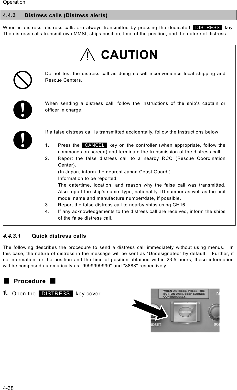
![Operation 4-39 222... Press and hold the DISTRESS key for 4 seconds until the countdown is completed. If released before the countdown is completed, displays the menu of 2.3 Distress call for the nature of distress selection. 333... The distress call will be sent. 444... Automatically remained in distress mode until received the acknowledgement. ¾ The distress call will be automatically repeated every 3.5 - 4.5 minutes until received the acknowledgement or manually breaks the mode. (The bottom line indicates the remaining time until the next distress call.) ¾ The distress call can be sent as many times as needed in this condition by the DISTRESS key operation mentioned above. 555... When acknowledged, the screen at right will be displayed and the alarm will sound growing louder gradually. Then lift the handset and request rescue using CH16 of the radiotelephone. ¾ The ALM lamp blinks in sync with the alarm sound. ¾ Only to silence the alarm, press the CANCEL key when displaying the screen at right. ¾ First, the responding station will call on the CH16, then acknowledge the receipt as follows. z "MAYDAY", z "this is", z Own ship's MMSI and call sign, position, nature of distress, and rescue requests The following popup screens will be displayed as appropriate in distress mode. Popup message Contents Notes Attention!/Restarting distress call soon… Notifies that the distress call will be resent within 12 seconds. Received other call. Break DISTRESS mode to view message? Equipment received a call but not the acknowledgement. To continue distress mode, select [Continue], or to cancel distress mode to check the received DSC call, select [Break] Now continuing DISTRESS call mode. Break this mode? Confirmation screen when pressed the CANCEL key in distress mode To continue distress mode, select [Continue], or to cancel distress mode, select [Break] Note Station1 TIME 23:59(UTC) POS 89゚59'S EXT 179゚59'W16CHDISTRESS Next DISTRESS call: 3.9min laterSQL[ITU] 2.3)Distress call Nature :[Fire ] Position:[NE] . [ 12゚34.5678'N] [123゚45.6789'E] UTC :[12:20] .Station1 TIME 23:59(UTC)CH70CH70Nature Press DISTRESS to send. [Cancel] DISTRESS call starts in 4 sec[ITU] Received Acknowledgement Type :Distress ACK... To :All ships ..... From :001234567...... Dist-ID :987654321...... Nature :Undesignated Position :34゚00.1234'N...Station1 TIME 23:59(UTC)16CH70 Press CANCEL to silence alarm.CH [ITU]](https://usermanual.wiki/Japan-Radio/JHS-780D/User-Guide-999383-Page-83.png)
![Operation 4-40 4.4.3.2 Distress calls from the menu The following describes the procedure to send a distress call with the nature of distress selected in the menu. Also, if there is no valid information regarding the position and the time of position, the manual input is available in that menu. ■ Procedure ■ 111... Press the MENU key, and through hierarchical menus, select the 2.3 Distress call. Indicates "Undesignated" as the nature of distress by default, and the position information if obtained from a GPS automatically or entered manually. 222... Press ENT and select the nature of distress. The nature of distress is selectable from below. Nature of distress Contents Fire Fire, explosion Flooding Flooding Collision Collision Grounding Grounding Listing Listing, in danger of capsizingSinking Sinking Disabled Disabled and adrift Undesignated Undesignated distress Abandoning Abandoning ship Piracy attack Piracy/armed robbery attack Man overboard Man overboard 333... Press ENT. The cursor will move to Position. If already displayed the valid position and time of position, no entry is necessary and skip to step 7. 444... Press ENT and select the quadrant of the position with the jog dial. The quadrant will be changed as NE → NW → SE → SW. 2.3)Distress call Nature :[Undesignated ] Position:[NE] [ 12゚34.5678'N] [123゚45.6789'E] UTC :[12:20] Press DISTRESS to send. [Cancel] 2.3)Distress call Nature :[Undesignated ] Position:[NE] [ 12゚34.5678'N] [123゚45.6789'E] UTC :[12:20] Press DISTRESS to send. [Cancel] 2.3)Distress call Nature :[Flooding ] Position:[NE] [ 12゚34.5678'N] [123゚45.6789'E] UTC :[12:20] Press DISTRESS to send. [Cancel] 2.3)Distress call Nature :[Flooding ] Position:[NE] [ 12゚34.5678'N] [123゚45.6789'E] UTC :[12:20] Press DISTRESS to send. [Cancel]](https://usermanual.wiki/Japan-Radio/JHS-780D/User-Guide-999383-Page-84.png)
![Operation 4-41 555... After pressing ENT, input the latitude and longitude using the numeric keypad. After registered the every digit, input the UTC. 666... After completed the registrations, the cursor will return to Nature. 777... Open the DISTRESS key cover. 888... Press and hold the DISTRESS key for 4 seconds until the countdown is completed. The rest of the procedure is the same as described in the "Quick distress call". 2.3)Distress call Nature :[Flooding ] Position:[NE] [ 34゚00.1234'N] [140゚00.1234'E] UTC :[12:20] Press DISTRESS to send. [Cancel] 2.3)Distress call Nature :[Flooding ] Position:[NE] [ 34゚00.1234'N] [140゚00.1234'E] UTC :[12:34] Press DISTRESS to send. [Cancel] Note 2.3)Distress call Nature :[Fire ] Position:[NE] . [ 12゚34.5678'N] [123゚45.6789'E] UTC :[12:20] .Station1 TIME 23:59(UTC)CH70CH70Nature Press DISTRESS to send. [Cancel] DISTRESS call starts in 4 sec[ITU]](https://usermanual.wiki/Japan-Radio/JHS-780D/User-Guide-999383-Page-85.png)
![Operation 4-42 4.4.3.3 Receiving a distress call When a distress call is received, the message will be immediately displayed with the specific two-tone alarm sound identical to the urgency. WARNING If a distress call is received, make sure to inform the ship's captain or officer in charge. Doing so may save the lives of the crew and passengers on the ship in distress. ■ Procedure ■ 111... When a distress call is received, the distress message will be displayed. The alarm lamp will blink in sync with the alarm sound, gradually growing louder. The example message contains the following information. - Type: Distress call - Caller’s MMSI: 431001234 - Nature of distress: Fire, explosion - Position & the time: North latitude 12º 34.5678' East longitude 123º 45.6789' 12:14 - EOS: End of sequence (appears by scrolling) 222... Press the CANCEL key to stop the alarm, and the screen at right will be displayed. 333... Select "OK/CH16 watch” with the jog dial and press ENT to watch on CH16. Keep watch for at least 5 minutes and, if necessary, notify a coast station or concerned administration. Station1 TIME 23:59(UTC) POS 89゚59'S EXT 179゚59'W16CHSQLCH70CHSW[ITU] Received distress message Type :Distress....... From :431001234...... Nature :Fire........... Position :12゚34.5678'N... 123゚45.6789'E.. UTC :12:14..........Station1 TIME 23:59(UTC)16CH70 Press CANCEL to silence alarm.CH [ITU] Received distress message Type :Distress....... From :431001234...... Nature :Fire........... Position :12゚34.5678'N... 123゚45.6789'E.. UTC :12:14..........Station1 TIME 23:59(UTC)16CH70 [OK/CH16 watch] [Cancel]CH [ITU]](https://usermanual.wiki/Japan-Radio/JHS-780D/User-Guide-999383-Page-86.png)
![Operation 4-43 4.4.3.4 Acknowledgement to a received distress call After receiving a distress call, ship stations have to watch on CH16. But if received the distress call repeatedly, ship stations (inc. own ship) are allowed to transmit a DSC acknowledgement to terminate the call only after consulting with an RCC or a coast station and being directed to do so. ■ Procedure ■ 111... Press the MENU key, and through hierarchical menus, select the 4.1 Received distress list. On the bottom line, the MMSI of the ship highlighted by the cursor will be displayed. 222... Select the call to be acknowledged and press ENT. The distress message will be displayed. 333... Select ACK with the jog dial and press ENT. The popup message at right will be displayed. 444... After confirmed the popup message, select "Continue" and press ENT to send the acknowledgement. After the transmission, the channel will be set to 16 automatically. After sending the acknowledgement, commence the distress traffic via radiotelephony on CH16. z "MAYDAY" z Repeat the 9-digit identity (MMSI) of the ship in distress, 3 times. z "this is" z Repeat own ship’s 9-digit identity (MMSI), 3 times. z ""RECEIVED MAYDAY" Note 4.1)Received distress list Date/Time Type '06-12-31 11:20 Distress From: 431012345 Station1 TIME 23:59(UTC) POS 89゚59'S EXT 179゚59'W16CHSQLCH70CHSW[ITU]Received distress message Type :Distress From :431012345 Nature :Fire Position :34゚00.1234'S 140゚00.1234'W UTC :11:20 [Close] [ACK] [Relay] Received distress message From :431001234 Nature :Fire Position :34゚00.1234'S 140゚00.1234'W UTC :14:55 EOS :EOS [Close] [ACK] [Relay] - Attention ! - Send this call only when being directed by administration. [Continue] [Cancel]](https://usermanual.wiki/Japan-Radio/JHS-780D/User-Guide-999383-Page-87.png)
![Operation 4-44 4.4.4 Distress relay calls on behalf of someone else (Proxy distress calls) If another ship is in distress but itself unable to make a distress call, and the master of the ship considers that further help is necessary, the distress relay call on behalf of the ship can be transmitted using "Proxy distress call" menu. In this case, compose a distress relay call format by inputting the MMSI (if known), the ship's position and the time of position (if known), and the nature of distress to send to all ships or a coast station. CAUTION When sending a proxy distress call (DROBOSE), do NOT press the DISTRESS key. Doing so will inconvenience local shipping and Rescue Centers. (This proxy distress call can be sent via [Call] button displayed on the screen.) 4.4.4.1 All ships calls Transmits a proxy distress call (DROBOSE) to all ships. ■ Procedure ■ 111... Press the MENU key, and through hierarchical menus, select 2.4.1 All ships call. 222... If the 9-digit identity (MMSI) of the ship in distress is known, press ENT and input it. If unknown, move the cursor to Nature with the jog dial and skip to step 4 below. 333... Press ENT. The cursor will move to Nature. 2.4.1)All ships call Type :Proxy distress Dist-ID :[ ] Nature :[Fire ] Position:[NE] [ ゚ . ' ] [ ゚ . ' ] UTC :[ : ] [ OK ] [Cancel] 2.4.1)All ships call Type :Proxy distress Dist-ID :[123456789] Nature :[Fire ] Position:[NE] [ ゚ . ' ] [ ゚ . ' ] UTC :[ : ] [ OK ] [Cancel] 2.4.1)All ships call Type :Proxy distress Dist-ID :[0 ] Nature :[Fire ] Position:[NE] [ ゚ . ' ] [ ゚ . ' ] UTC :[ : ] [ OK ] [Cancel]](https://usermanual.wiki/Japan-Radio/JHS-780D/User-Guide-999383-Page-88.png)
![Operation 4-45 444... Press ENT and select the nature of distress with the jog dial. The nature of distress is selectable from below. Nature of distress Contents Fire Fire, explosion Flooding Flooding Collision Collision Grounding Grounding Listing Listing, in danger of capsizing Sinking Sinking Disabled Disabled and adrift Undesignated Undesignated distress Abandoning Abandoning ship Piracy attack Piracy/armed robbery attack Man overboard Man overboard EPIRB emission Received DSC VHF EPIRB signal 555... Press ENT. The cursor will move to Position. 666... If the position and the time of position of the ship in distress are known, press ENT. If unknown, move the cursor to OK with the jog dial and skip to step 8 below. 777... Input the quadrant, latitude, longitude and the time of position, respectively and press ENT. The cursor will move to OK. 888... Press ENT. The sending confirmation screen will appear. Further, unregistered items will be indicated as "Unknown". 2.4.1)All ships call Type :Proxy distress Dist-ID :[123456789] Nature :[Fire ] Position:[NE] [ ゚ . ' ] [ ゚ . ' ] UTC :[ : ] [ OK ] [Cancel] 2.4.1)All ships call Type :Proxy distress Dist-ID :[123456789] Nature :[Fire ] Position:[NE] [ ゚ . ' ] [ ゚ . ' ] UTC :[ : ] [ OK ] [Cancel] 2.4.1)All ships call Type :Proxy distress Dist-ID :[123456789] Nature :[Fire ] Position:[NE] [ ゚ . ' ] [ ゚ . ' ] UTC :[ : ] [ OK ] [Cancel] 2.4.1)All ships call Type :Proxy distress Dist-ID :[123456789] Nature :[Fire ] Position:[NE] [ 12゚34.5678'N] [123゚45.6789'E] UTC :[12:20] [ OK ] [Cancel] 2.4.1)All ships call Type :Proxy distress Dist-ID :123456789 Nature :Fire Position :12゚34.5678'N 123゚45.6789'E UTC :12:20 [Call] [Cancel]](https://usermanual.wiki/Japan-Radio/JHS-780D/User-Guide-999383-Page-89.png)
![Operation 4-46 999... Press ENT to transmit the call. Watch on CH16 and wait for the acknowledgement. After acknowledged, commence the distress traffic regarding the ship in distress. - When acknowledged from a coast station via DSC, the screen at right (lower) will be displayed and the specific alarm will sound growing louder gradually. - The ALM lamp blinks in sync with the alarm sound. - As a general rule, ship stations are allowed to acknowledge only by the radiotelephone. 4.4.4.2 Coast station calls Transmits a proxy distress call (DROBOSE) to a specified coast station. ■ Procedure ■ 111... Press the MENU key, and through hierarchical menus, select 2.4.2 Coast station call. 222... Press ENT to display the coast station list, and select the desired station with the jog dial. The procedure is identical to the case of the routine calls. 333... Pressing ENT will move the cursor to Dist-ID. If the 9-digit identity (MMSI) of the ship in distress is known, press ENT and input it. If unknown, move the cursor to Nature with the jog dial and skip to step 5 below. Note Station1 TIME 23:59(UTC) POS 89゚59'S EXT 179゚59'W16CHSQLCH70CHSW[ITU]2.4.2)Coast station Type :Proxy distress Address :[00 ] Dist-ID :[ ] Nature :[Undesignated ] Position:[NE] [ ゚ . ' ] [ ゚ . ' ] [ OK ] [Cancel] 2.4.2)Coast station Type :Proxy distress Address :[001011111] Dist-ID :[ ] Nature :[Undesignated ] Position:[NE] [ ゚ . ' ] [ ゚ . ' ] [ OK ] [Cancel] Coast station list [A] NAME MMSI Argentina 001234567 Australia Azerbaijan Bolivia Bangladesh 002222222 003333333 004444444 005555555 Select the initial of the name. ABCDEFGHIJKLMNOPQRSTUVWXYZ Received distress message Type :Proxy dist-ACK. To :All ships...... From :001011111...... Dist-ID :987654321...... Nature :Fire........... Position :12゚34.5678'N...Station1 TIME 23:59(UTC)16CH70 Press CANCEL to silence alarm.CH [ITU]](https://usermanual.wiki/Japan-Radio/JHS-780D/User-Guide-999383-Page-90.png)
![Operation 4-47 444... Press ENT The cursor will move to Nature. 555... Press ENT and select the nature of distress with the jog dial. The nature of distress is selectable from below. Nature of distress Contents Fire Fire, explosion Flooding Flooding Collision Collision Grounding Grounding Listing Listing, in danger of capsizing Sinking Sinking Disabled Disabled and adrift Undesignated Undesignated distress Abandoning Abandoning ship Piracy attack Piracy/armed robbery attack Man overboard Man overboard EPIRB emission Received DSC VHF EPIRB signal 666... Press ENT. The cursor will move to Position. 777... If the position and the time of position of the ship in distress are known, press ENT. If unknown, move the cursor to OK button with the jog dial and skip to step 9 below. 888... Input the quadrant, latitude, longitude and the time of position, respectively and press ENT. The cursor will move to OK. 2.4.2)Coast station Type :Proxy distress Address :[001011111] Dist-ID :[987654321] Nature :[Undesignated ] Position:[NE] [ ゚ . ' ] [ ゚ . ' ] [ OK ] [Cancel] 2.4.2)Coast station Type :Proxy distress Address :[001011111] Dist-ID :[987654321] Nature :[Fire ] Position:[NE] [ ゚ . ' ] [ ゚ . ' ] [ OK ] [Cancel] 2.4.2)Coast station Address :[001011111] Dist-ID :[987654321] Nature :[Fire ] Position:[NE] [ 12゚34.5678'N] [123゚45.6789'E] UTC :[12:20] [ OK ] [Cancel] 2.4.2)Coast station Type :Proxy distress Address :[001011111] Dist-ID :[987654321] Nature :[Fire ] Position:[NE] [ ゚ . ' ] [ ゚ . ' ] [ OK ] [Cancel] 2.4.2)Coast station Type :Proxy distress Address :[001011111] Dist-ID :[987654321] Nature :[Fire ] Position:[NE] [ ゚ . ' ] [ ゚ . ' ] [ OK ] [Cancel]](https://usermanual.wiki/Japan-Radio/JHS-780D/User-Guide-999383-Page-91.png)
![Operation 4-48 999... Press ENT. The sending confirmation screen will appear. Further, unregistered items will be indicated as "Unknown". 111000... Press ENT to transmit the call. Watch on CH16 and wait for the acknowledgement. 111111... When acknowledged, the screen at right will be displayed and the alarm will sound growing louder gradually. Then lift the handset and commence distress traffic for the ship in distress. ¾ The ALM lamp blinks in sync with the alarm sound. ¾ Only to silence the alarm, press the CANCEL key when displaying the screen at right. 2.4.2)Coast station call Type :Proxy distress Address :001011111 Dist-ID :987654321 Nature :Fire Position :12゚34.5678'N 123゚45.6789'E UTC :12:20 [Call] [Cancel] Station1 TIME 23:59(UTC) POS 89゚59'S EXT 179゚59'W16CHSQLCH70CHSW[ITU] Received distress message Type :Proxy dist-ACK. To :Individual..... From :001011111...... Dist-ID :987654321...... Nature :Fire........... Position :12゚34.5678'N...Station1 TIME 23:59(UTC)16CH70 Press CANCEL to silence alarm.CH [ITU]](https://usermanual.wiki/Japan-Radio/JHS-780D/User-Guide-999383-Page-92.png)
![Operation 4-49 4.4.4.3 Receiving a proxy distress call When received a distress relay call (DROBOSE) directed to all ships, the ship stations (inc. your own ship) are allowed to acknowledge only by the radiotelephone. (Receiving a distress relay call from a coast station is the same.) ■ Procedure ■ 111... When received a proxy distress call, the screen at right will be displayed. ¾ The specific alarm will sound growing louder gradually. ¾ The ALM lamp blinks in sync with the alarm sound. ¾ The example message contains the following information. - Type: Proxy distress call - To: All ships - Caller’s MMSI: 123456789 - MMSI of ship in distress: 987654321 - Nature of distress: Fire, explosion - Position and Time: North latitude 12º 34.5678' (Longitude and the time appears by scrolling.) - EOS: ACK is requested. (appears by scrolling) 222... Press the CANCEL key to stop the alarm, and the screen at right will be displayed. 333... Select OK/CH16 watch with the jog dial and press ENT then watch on CH16. Keep watch for at least 5 minutes and, if necessary, notify a coast station or concerned administration via radiotelephony. Station1 TIME 23:59(UTC) POS 89゚59'S EXT 179゚59'W16CHSQLCH70CHSW[ITU] Received distress message Type :Proxy distress. To :All ships...... From :123456789...... Dist-ID :987654321...... Nature :Fire........... Position :12゚34.5678'N...Station1 TIME 23:59(UTC)16CH70 Press CANCEL to silence alarm.CH [ITU] Received distress message Type :Proxy distress. To :All ships...... From :123456789...... Dist-ID :987654321...... Nature :Fire........... Position :12゚34.5678'N...Station1 TIME 23:59(UTC)16CH70[OK/CH16 watch] [Cancel]CH [ITU]](https://usermanual.wiki/Japan-Radio/JHS-780D/User-Guide-999383-Page-93.png)
![Operation 4-50 4.4.5 Distress relay calls After receiving a distress call, ship stations have to watch on CH16 for at least 5 minutes. But if there is no distress traffic on CH16 in the meantime, the distress relay call will be available to inform a coast station of the distress call transmitted by the ship in distress. 4.4.5.1 Sending a distress relay call A distress relay call can be composed from the log of the received distress message. ■ Procedure ■ 111... Press the MENU key, and through hierarchical menus, select the 4.1 Received distress list. On the bottom line, the MMSI of the ship highlighted by the cursor will be displayed. 222... Select the distress call to be relayed and press ENT. The distress message will be displayed. 333... Select Relay with the jog dial and press ENT. The popup message at right will be displayed. 444... After confirmed the popup message, select "Continue" and press ENT. The address inputting screen will be displayed. 555... Press ENT to display the station list of both the coast stations and the ship stations, and select the desired station with the jog dial. When inputting the MMSI manually, press the CANCEL key to return to the previous screen and input it using the numeric keypad. 4.1)Received distress list Date/Time Type '06-12-31 14:55 Distress From: 987654321 Distress relay call Address :[ ] [ OK ] [Cancel] Received distress message Type :Distress From :987654321 Nature :Fire Position :34゚00.1234'N 140゚00.1234'E UTC :14:55 [Close] [ACK] [Relay] Received distress message From :431001234 Nature :Fire Position :34゚00.1234'S 140゚00.1234'W UTC :14:55 EOS :EOS [Close] [ACK] [Relay] - Attention ! - Normally, this call should be sent to coast station. [Continue] [Cancel] Station list [A] NAME MMSI Argentina 001234567 Australia Azerbaijan Bolivia Bangladesh 002222222 003333333 004444444 005555555 Select the initial of the name. ABCDEFGHIJKLMNOPQRSTUVWXYZ](https://usermanual.wiki/Japan-Radio/JHS-780D/User-Guide-999383-Page-94.png)
![Operation 4-51 666... Press ENT. The cursor will move to OK. 777... Press ENT. The sending confirmation screen will appear. 888... Press ENT to send the distress relay call. After the transmission, the channel will be set to 16 automatically. 999... When acknowledged, the screen at right will be displayed and the alarm will sound growing louder gradually. Then lift the handset and commence distress traffic for the ship in distress. ¾ The ALM lamp blinks in sync with the alarm sound. ¾ Only to silence the alarm, press the CANCEL key when displaying the screen at right. Distress relay call Address :[001011111] [ OK ] [Cancel] Distress relay call Address :001011111 [Call] [Cancel] Station1 TIME 23:59(UTC) POS 89゚59'S EXT 179゚59'W16CHSQLCH70CHSW[ITU] Received distress message Type :Dist-relay ACK. To :Individual..... From :001011111...... Dist-ID :987654321...... Nature :Fire........... Position :34゚00.1234'N...Station1 TIME 23:59(UTC)16CH70 Press CANCEL to silence alarm.CH [ITU]](https://usermanual.wiki/Japan-Radio/JHS-780D/User-Guide-999383-Page-95.png)
![Operation 4-52 4.4.5.2 Receiving a distress relay call Normally, ship stations receive a distress relay call in the following situations. ・ When a coast station has transmitted an all ships or individual distress relay call. ・ When another ship station has transmitted a distress relay call to all ships, an individual distress relay call, or a geographic distress relay call to a specific sea area. As a general rule, the ship stations should respond via radiotelephony after receiving a distress relay call. But if called individually by another ship station, and if allowed by a coast station, a distress relay acknowledgement can be transmitted as follows. Further, a distress relay acknowledgement can be composed from the log of the received distress relay message. ■ Procedure ■ 111... When a distress relay call is received, the screen at right will be displayed. ¾ The specific alarm will sound growing louder gradually. ¾ The ALM lamp blinks in sync with the alarm sound. ¾ The example message contains the following information. - Type: Distress relay call - To: Individual (own ship) - Caller’s MMSI: 123456789 - MMSI of ship in Distress: 987654321 - Nature of distress: Fire, explosion - Position and Time: North latitude 34º 00.1234' (Longitude and the time appears by scrolling.) - EOS: ACK is requested. (appears by scrolling) 222... Press the CANCEL key to stop the alarm, and the screen at right will be displayed. 333... Select OK/CH16 watch with the jog dial and press ENT then watch on CH16. ¾ Keep watch for at least 5 minutes. ¾ When acknowledging the distress relay, follow the procedure described below. Station1 TIME 23:59(UTC) POS 89゚59'S EXT 179゚59'W16CHSQLCH70CHSW[ITU] Received distress message Type :Distress relay. To :Individual..... From :123456789...... Dist-ID :987654321...... Nature :Fire........... Position :34゚00.1234'N...Station1 TIME 23:59(UTC)16CH70 Press CANCEL to silence alarm.CH [ITU] Received distress message Type :Distress relay. To :Individual..... From :123456789...... Dist-ID :987654321...... Nature :Fire........... Position :34゚00.1234'N...Station1 TIME 23:59(UTC)16CH70[OK/CH16 watch] [Cancel]CH [ITU]](https://usermanual.wiki/Japan-Radio/JHS-780D/User-Guide-999383-Page-96.png)
![Operation 4-53 444... Press the MENU key, and through hierarchical menus, select the 4.1 Received distress list. On the bottom line, the MMSI of the ship highlighted by the cursor will be displayed. 555... Select the distress relay call to be acknowledged and press ENT. The distress relay message will be displayed. 666... Select ACK with the jog dial, and press ENT. The popup message at right will be displayed. 777... After confirmed the popup message, select "Continue" and press ENT to send the distress relay acknowledgement. After the transmission, the channel will be set to 16 automatically. Then wait for a call via radiotelephony on that channel. 4.1)Received distress list Date/Time Type '06-01-10 08:45 Relay From: 123456789 Station1 TIME 23:59(UTC) POS 89゚59'S EXT 179゚59'W16CHSQLCH70CHSW[ITU]Received distress message Type :Distress relay To :Individual From :123456789 Dist-ID :987654321 Nature :Fire Position :34゚00.1234'N [Close] [ACK] Received distress message Dist-ID :987654321 Nature :Fire Position :34゚00.1234'N 124゚00.5678'E UTC :12:12 EOS :ACK RQ [Close] [ACK] - Attention ! - Send this call only when being directed by administration. [Continue] [Cancel]](https://usermanual.wiki/Japan-Radio/JHS-780D/User-Guide-999383-Page-97.png)
![Operation 4-54 4.5 Simple DSC test call The following describes simple procedure to send a DSC test call from the dedicated menu. (Note: This menu is prepared to simplify the test call procedure in the menu 2.1.2 Specific station, and both of the message formats are exactly the same.) ■ Procedure ■ 111... Press the MENU key, and through hierarchical menus, select the 3. DSC test call. The address inputting screen will be displayed. If entered previously, the address will be appeared as a default value. 222... Input the desired station's MMSI and press ENT. The procedure is identical to the case of an individual call for safety. (The list shows ship stations first, and then coast stations.) 333... If the contents are correct, press ENT. The sending confirmation screen will appear. 444... Press ENT to transmit the call. After completed the transmission, the popup screen shown at right will be displayed to wait the acknowledgement. If received no response for 5 minutes, the screen will return to the step 1 mentioned above. 555... When received the acknowledgement, the screen shows the message with the alarm as shown at right. Pressing CANCEL stops alarm and after that, pressing ENT returns to the status display. According to the condition of the station, the acknowledgement may not be received even if the equipment works normally. 3)DSC test call Address :[123456789] [ OK ] [Cancel] Note Note 3)DSC test call Address :[123456789] [ OK ] [Cancel] 3)DSC test call Address :123456789 [Call] [Cancel] 3)DSC test call Address :234567890 [Call] [Cancel] Waiting for Acknowledgement. [Cancel] Received safety message Format :Individual ACK From :123456789...... Type :Test........... EOS :ACK BQ.........Station1 TIME 23:59(UTC)16CH70 Press CANCEL to silence alarm.CH [ITU]](https://usermanual.wiki/Japan-Radio/JHS-780D/User-Guide-999383-Page-98.png)
![Operation 4-55 4.6 DSC call log Received DSC messages are classified as distress messages and as other messages. The 20 most recent messages for both types of received and transmitted are saved in the log. CAUTION A distress acknowledgement or a distress relay call can be transmitted from a received distress message stored in the log, but when sending such a kind of call, follow the instructions of the ship's captain or officer in charge. Received distress calls are automatically deleted after 48 hours to avoid accidental resending or other misoperation. Accordingly, if such messages cannot be read out, it is not a malfunction. 4.6.1 Received distress messages Received messages regarding distress calls and the acknowledgements, distress relay calls and the acknowledgements will be displayed in this received distress message log. Additionally, when receiving a distress call containing the same 5 messages, only one of those will be stored. ■ Procedure ■ 111... Press the MENU key, and through hierarchical menus, select the 4.1 Received distress list. ¾ On the bottom line, the MMSI of the ship highlighted by the cursor will be displayed. ¾ In the event of a receiving error (ECC error), "ECC error" will be indicated in the Type field. 222... To view a message, select a line by timestamp and/or message type, and press ENT. The selected message will be displayed. Also the screen shows Message handling menus at the bottom of the screen and enabled to handle the message as follows. (The handling menus will differ depending on the type of message .) - Close: Close the message and return to the list. - ACK: Send the acknowledgement to the caller. (In this case, to the ship in distress) - Relay: Send this message to a specified coast station as a distress relay call. 4.1)Received distress list Date/Time Type '06-12-31 11:20 ACK '06-12-31 11:15 '06-12-31 11:10 '06-12-30 08:55 Relay-ACK Distress Relay From: 431012345 Received distress message Type :Distress From :987654321 Nature :Fire Position :34゚00.1234'S 140゚00.1234'W UTC :14:55 [Close] [ACK] [Relay]](https://usermanual.wiki/Japan-Radio/JHS-780D/User-Guide-999383-Page-99.png)
![Operation 4-56 4.6.2 Received other messages Received messages regarding routine, safety, and urgency calls or the acknowledgements will be displayed in this received other message log. ■ Procedure ■ 111... Press the MENU key, and through hierarchical menus, select the 4.2 Received others list. ¾ On the bottom line, the MMSI of the ship highlighted by the cursor will be displayed. ¾ In the event of a receiving error (ECC error), "ERR" will be indicated in the CAT field. (Note: CAT: category, FMT: format) 222... To view a message, select a line by timestamp, category and/or format, and press ENT. The selected message will be displayed. Also the screen shows Message handling menus at the bottom of the screen and enabled to handle the message as follows. (The handling menus will differ depending on the type of message .) - Close: Close the message and return to the list. - ACK: Send the acknowledgement to the caller. - NACK: Send a negative acknowledgement with the reason to the caller. - New CH: Send the acknowledgement with another working channel proposal. - MMSI: Register the caller's ID. (The corresponding menu such as 9.4.1 Coast station list will be opened.) - TEL No: Register the PSTN caller's or recipient's telephone number. (Menu 9.4.4 PSTN number list will be - opened.) 4.2)Received others list Date/Time CAT FMT '06-11-23 15:30 RTN INDIV '06-11-20 22:15 '06-11-19 07:10 '06-11-15 18:33 URG SAF RTN ACK ALL GRP From: 123456789 Received routine message Format :Individual call From :123456789 Type :All modes RT Work CH :10 EOS :ACK RQ [Close] [ACK] [NACK] [New CH] [MMSI]](https://usermanual.wiki/Japan-Radio/JHS-780D/User-Guide-999383-Page-100.png)
![Operation 4-57 4.6.3 Transmitted messages Every transmitted message will be displayed in this transmitted message log. ■ Procedure ■ 111... Press the MENU key, and through hierarchical menus, select the 4.3 Transmitted calls list. On the bottom line, the address information (such as MMSI) of the line highlighted by the cursor will be displayed. 222... To view a message, select a line by timestamp, category and/or format, and press ENT. The selected message will be displayed. Also the screen shows Message handling menus at the bottom of the screen and enabled to handle the message as follows. (The handling menus will differ depending on the type of message .) - Close: Close the message and return to the list. - Resend: Resend this message to the same address. - Edit&Send: Make a new call after revising based on the message. 4.3)Transmitted calls list Date/Time CAT FMT '06-01-23 12:30 RTN INDIV '06-12-15 20:15 '06-12-13 18:10 '06-11-20 06:33 '06-11-18 08:45 URG SAF RTN RTN ACK ALL GRP INDIV To: 123456789 Transmitted routine message Format :Individual call To :123456789 Type :All modes RT Work CH :10 [Close] [Resend] [Edit&Send]](https://usermanual.wiki/Japan-Radio/JHS-780D/User-Guide-999383-Page-101.png)
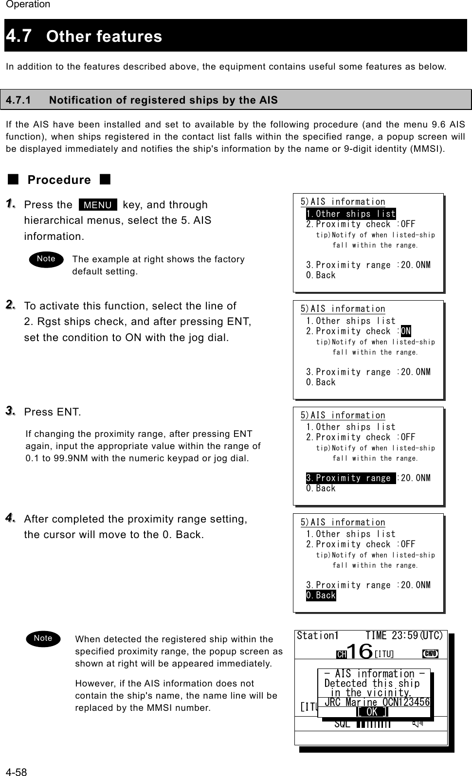
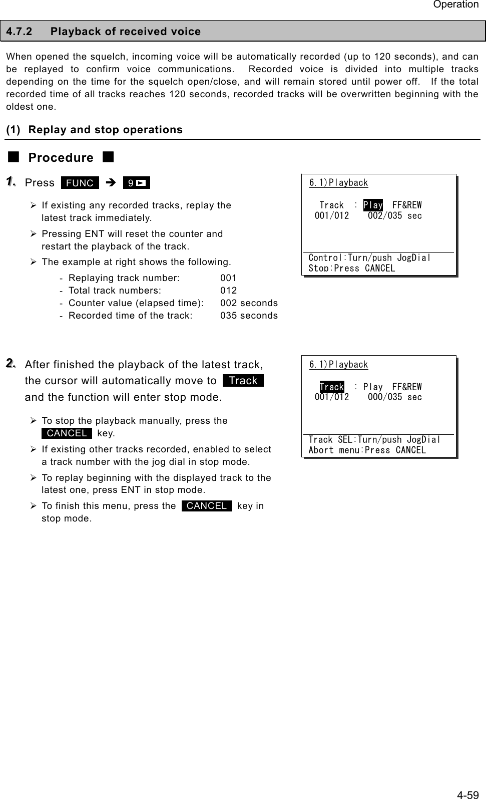
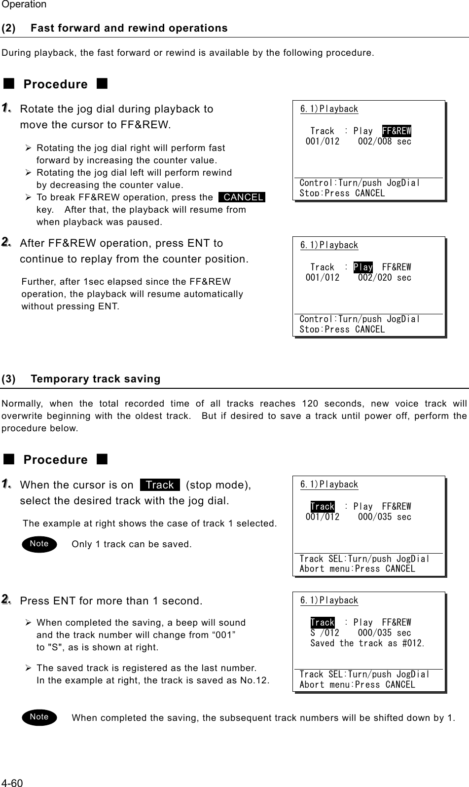
![Operation 4-61 (4) The saved track deletion To delete a saved track, perform the following procedure. (Powering off will delete all tracks.) ■ Procedure ■ 111... When the cursor is on Track (stop mode), select DEL with the jog dial. 222... Press ENT. A confirmation message will appear. 333... After confirmed the popup message, select "OK" and press ENT. After completed the deletion, track 1 will be selected, as shown at right. 6.1)Playback Track : Play FF&REW DEL/012 000/035 sec Track SEL:Turn/push JogDial Abort menu:Press CANCEL OK to delete the saved track? [ OK ] [Cancel] 6.1)Playback Track : Play FF&REW DEL/012 000/035 sec Track SEL:Turn/push JogDial Abort menu:Press CANCEL6.1)Playback Track : Play FF&REW 001/011 000/013 sec Track SEL:Turn/push JogDial Abort menu:Press CANCEL](https://usermanual.wiki/Japan-Radio/JHS-780D/User-Guide-999383-Page-105.png)
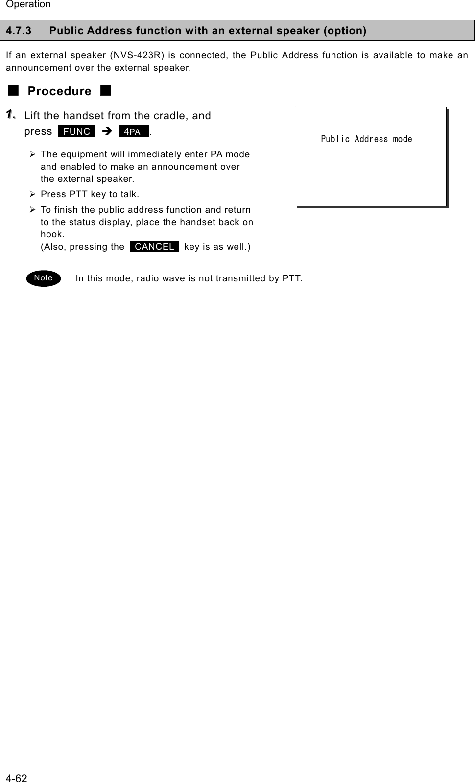
![Operation 4-63 4.7.4 Intercom If multiple controllers (NCM-1770) are connected, the intercom is available between two of them. (1) Calling another controller ■ Procedure ■ 111... Lift the handset from the cradle, and press FUNC Î 5 . ¾ The controller list will be displayed. ¾ The example at right shows that the following controllers are connected. - Address 1: Station1 - Address 2: Calling controller - Address 3: Station3 - Address 4: Station4 (Address 5 controller is not connected.) 222... Select a recipient with the jog dial and press ENT. ¾ The screen at right will be displayed and the intercom call will start. ¾ To cancel the calling, press the CANCEL key or hang up the handset while calling. - If the handset of the recipient has been left in the off-hook condition, the call will not start, and the screen shown at right will be displayed. Then press ENT to return to the step 1. - If not answered within 30 seconds, the screen shown at right will be displayed. Then press ENT to return to the step 1. 333... After answered the phone, the screen shown at right will be displayed and enabled to start the communication. ¾ Press PTT key to talk. ¾ To finish the intercom, place the handset back on hook. Intercom mode State: Time out [ OK ] 6.3)Intercom 1.Station1 2.(Own station) 3.Station3 4.Station4 5.(N/A) 0.Back INT COM Intercom mode State: Calling Intercom mode State: Connected Note Intercom mode State: Busy [ OK ]](https://usermanual.wiki/Japan-Radio/JHS-780D/User-Guide-999383-Page-107.png)
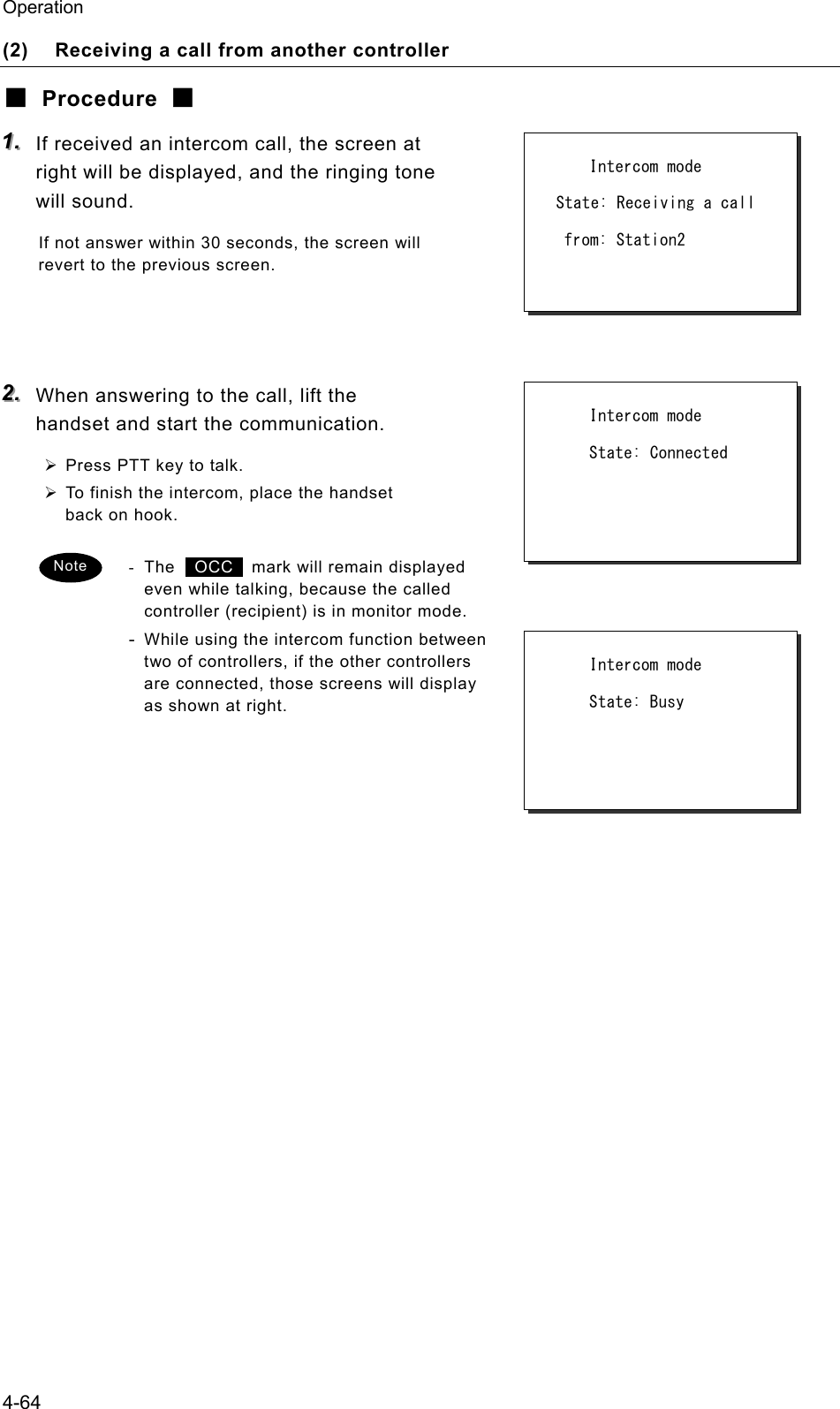
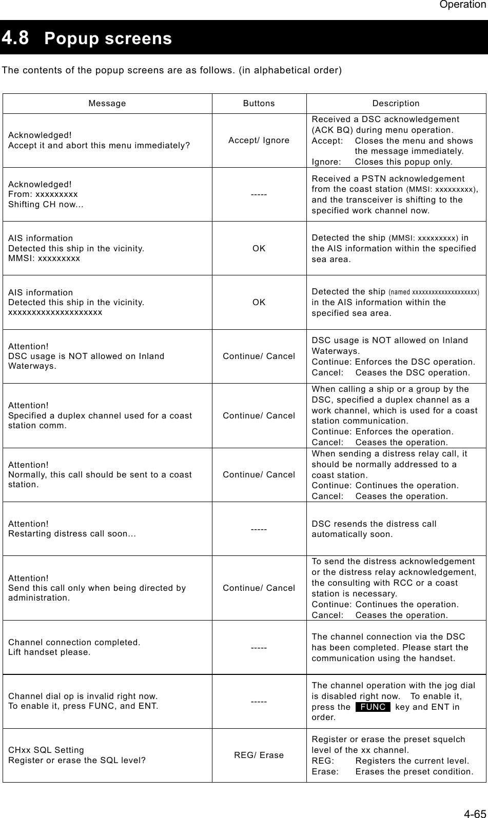
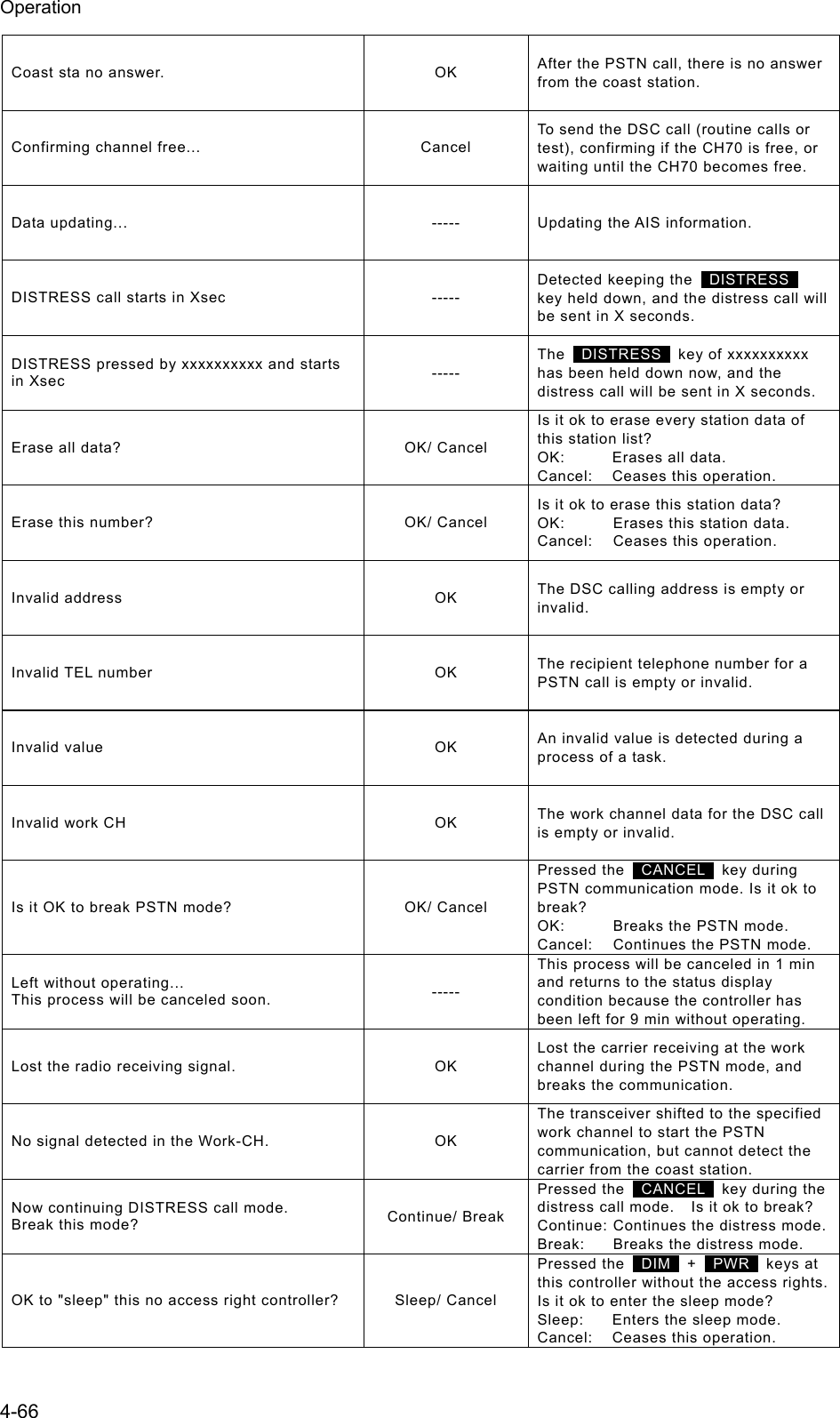
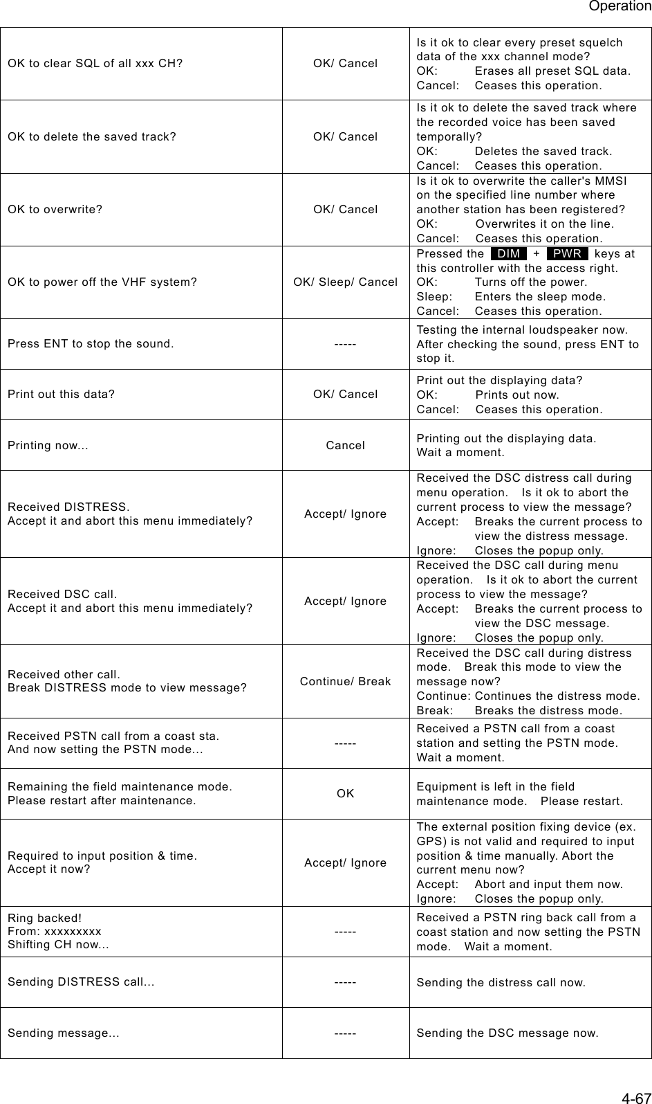
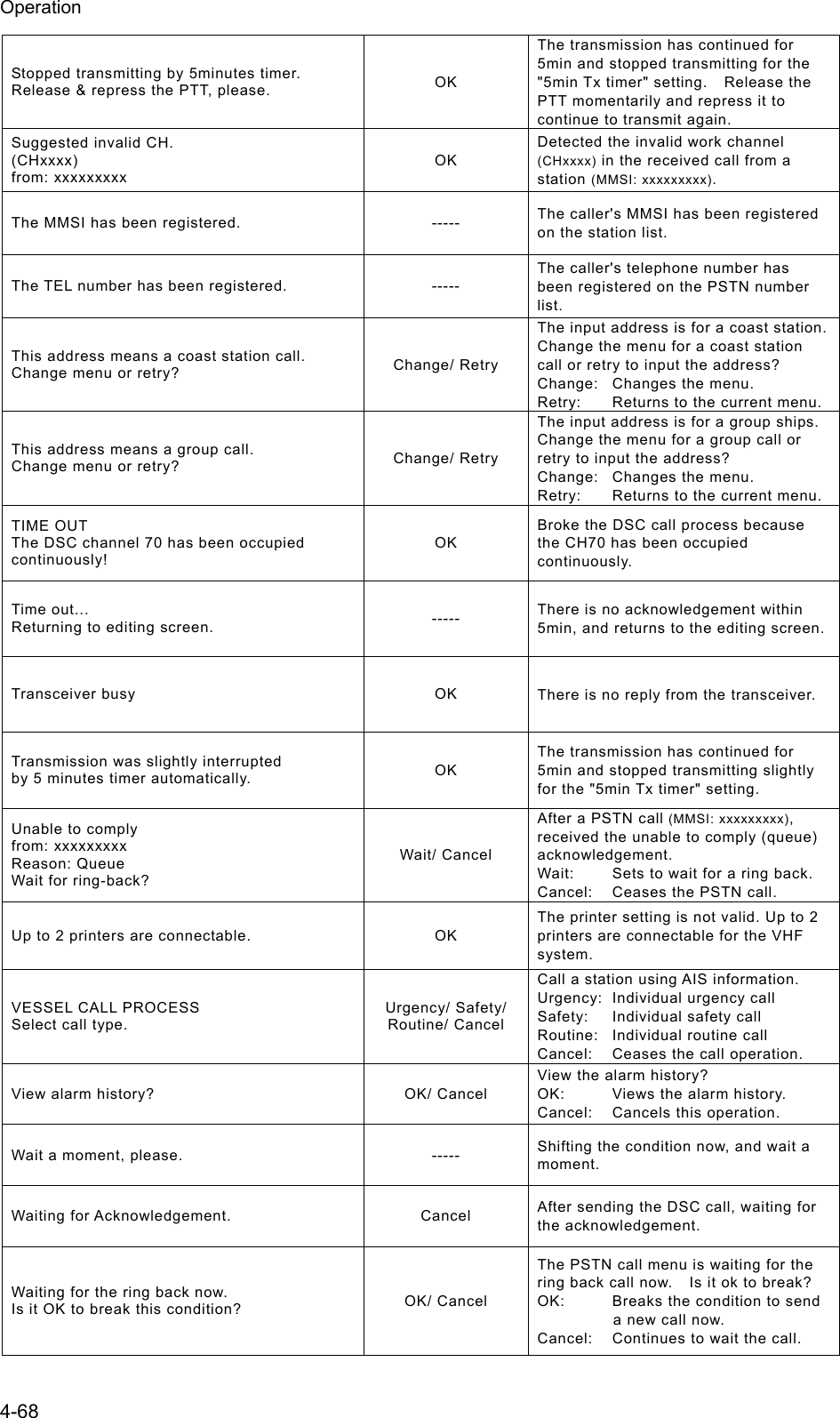
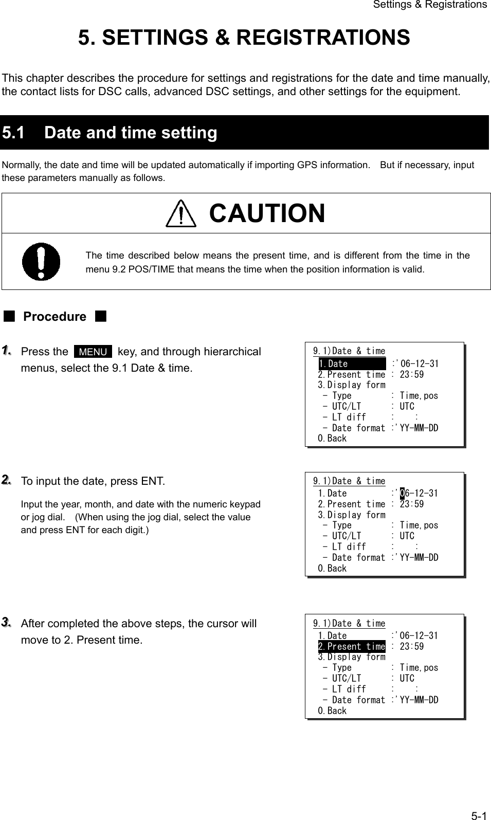
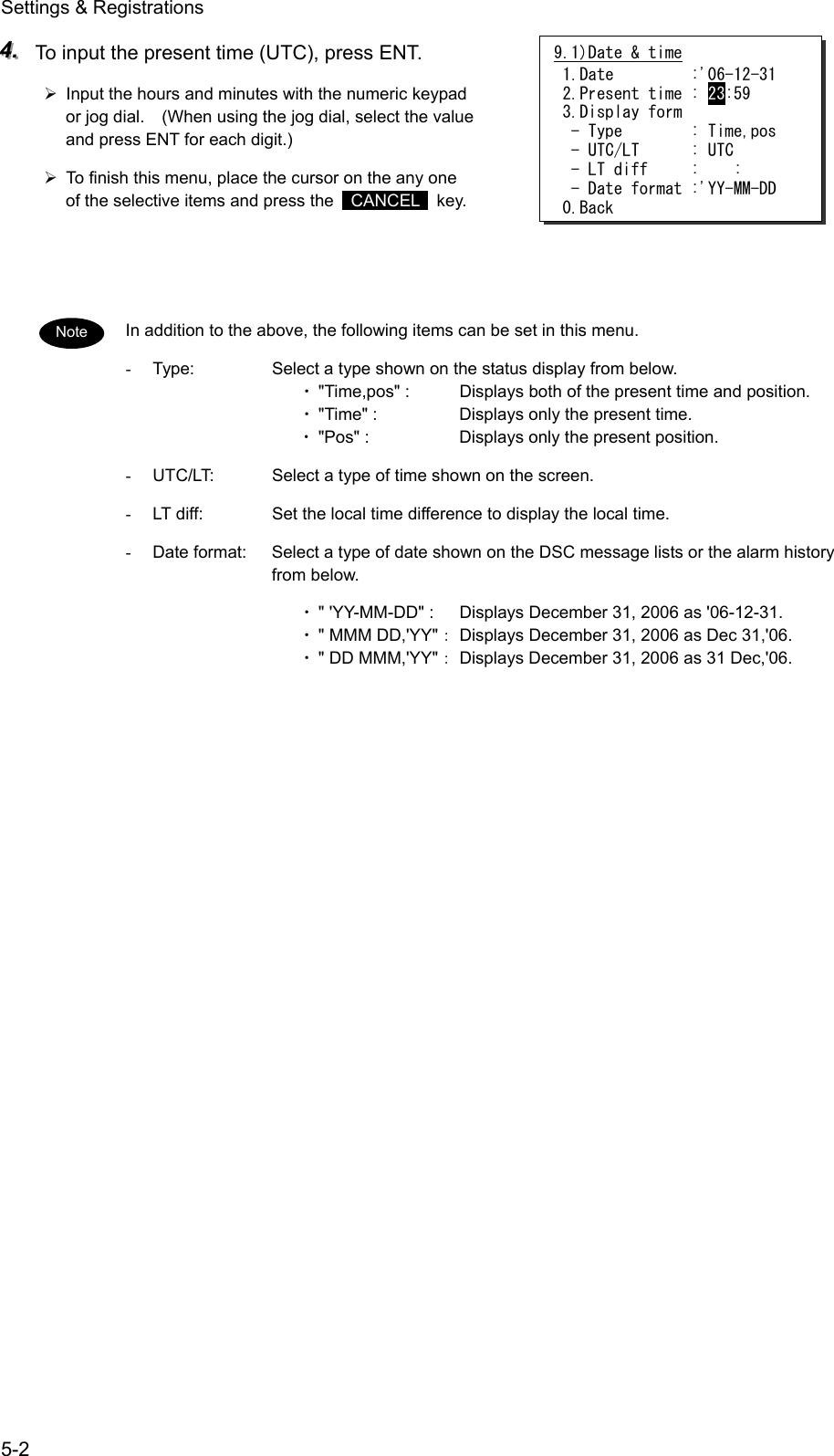
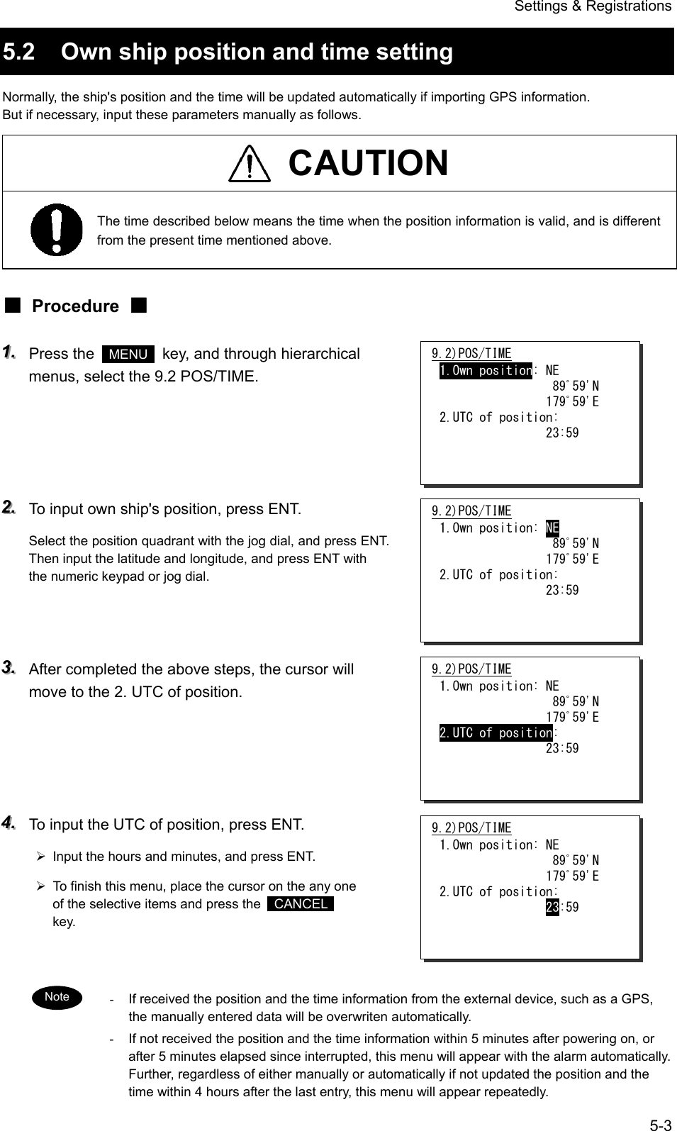
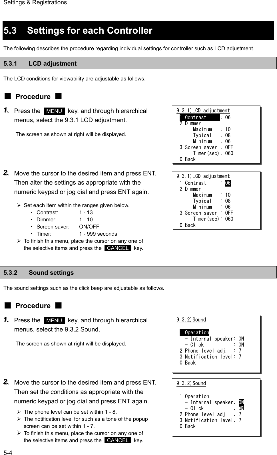
![Settings & Registrations 5-5 5.3.3 User key assignment User key assignment enables the desired menu to be displayed immediately without moving through the hierarchy menus, and is assignable as follows. ■ Procedure ■ 111... Press the MENU key, and through hierarchical menus, select the 9.3.3 User key assign. The screen at right will be displayed. If already been registered, the cursor will be placed on that menu. 222... Move the cursor to the desired menu to be registered with the jog dial. The assignable menus are as follows. 1. 2. 3. 4. 5. 6. 7. 8. 9. 10. 11. 12. 13. 14. 15. 16. 17. 18. DSC coast station call DSC ship station call DSC PSTN call DSC group call DSC emergency call DSC test call DSC logs AIS other ships list AIS proximity range Playback Public address Intercom Scan Dual watch Memory channel list Private channel Weather channel Region (Menu1.1) (Menu1.2) (Menu1.3) (Menu1.4) (Menu2) (Menu3) (Menu4) (Menu5.1) (Menu5.3) (Menu6.1) (Menu6.2) (Menu6.3) (Menu7.1) (Menu7.2) (Menu7.3.1) (Menu7.4) (Menu7.5) (Menu7.6) 19.20.21.22.23.24.25.26.27.28.29.30.31.32.CH SQL setting Self diagnosis DSC loop Alarm information System information DSC AF inspection Date & time POS/TIME My controller Contact list DSC operation Printer property Dedicated ENT key CH dial lock ON/OFF (Menu7.7) (Menu8.1) (Menu8.1.5) (Menu8.2) (Menu8.3) (Menu8.5) (Menu9.1) (Menu9.2) (Menu9.3) (Menu9.4) (Menu9.5) (Menu9.7) --- --- 333... Press ENT to complete registration. ¾ After registration, the screen will return to the previous hierarchical menu as shown at right. ¾ To finish this menu, place the cursor on the any one of the selective items and press the CANCEL key. When the USER key is pressed in the factory default setting, this menu is immediately displayed. 9.3.3)User key assign 1.DSC coast station call 2.DSC ship station call 3.DSC PSTN call 4.DSC group call 5.DSC emergency call 6.DSC test call 7.DSC logs 9.3.3)User key assign 1.DSC coast station call 2.DSC ship station call 3.DSC PSTN call 4.DSC group call 5.DSC emergency call 6.DSC test call 7.DSC logs 9.3)My controller 1.LCD adjustment 2.Sound 3.User key assign 4.Name :[Station1 ] 5.Hook switch: Valid 6.Off-hook notice: OFF 0.Back Note](https://usermanual.wiki/Japan-Radio/JHS-780D/User-Guide-999383-Page-117.png)
![Settings & Registrations 5-6 5.3.4 Name a controller When connecting multiple controllers, each controller can be named respectively to make identification easier. The name of each controller is always displayed on the top left of the screen. ■ Procedure ■ 111... Press the MENU key and through hierarchical menus, select the 9.3 My controller. The screen as shown at right will be displayed. 222... Move the cursor to the 4. Name with the numeric keypad or jog dial. 333... Press ENT to name the controller. ¾ Up to 10 alphanumeric characters available. ¾ Assigned "StationX (X: address No.)" by default. ¾ The following characters are available. ・ Alphabet (capital and small letters) ・ Numbers 0 - 9 ・ The following signs, space and determination(◄). [ ] _ " # % & ' ( ) ? @ + - / = : ; < > 444... Select a character and press ENT one by one. ¾ To change the character at the cursor position, rotate the jog dial to select the character, and press ENT to move the cursor to the right. Further, when using the numeric keypad to input numbers, pressing ENT is not needed. ¾ Only to move the cursor to the right, press ENT. ¾ To return to the previous letter, press the CANCEL key. ¾ To complete the name entry of 10 characters long, press ENT after selecting the last character by the jog dial. Or if less than 10 characters long, following the name, select the determination as shown at right, and press ENT. The characters sequence shown by turning the jog dial is as follows. ◄ A B C D E F G H I J K L M N O P Q R S T U V W X Y Z a b c d e f g h i j k l m n o p q r s t u v w x y z [ ] _ " # % & ' ( ) ? @ + - / = : ; < > 0 1 2 3 4 5 6 7 8 9 (space) 9.3)My controller 1.LCD adjustment 2.Sound 3.User key assign 4.Name :[Station1 ] 5.Hook switch: Valid 6.Off-hook notice: OFF 0.Back 9.3)My controller 1.LCD adjustment 2.Sound 3.User key assign 4.Name :[Station1 ] 5.Hook switch: Valid 6.Off-hook notice: OFF 0.Back 9.3)My controller 1.LCD adjustment 2.Sound 3.User key assign 4.Name :[Station1 ] 5.Hook switch: Valid 6.Off-hook notice: OFF 0.Back 9.3)My controller 1.LCD adjustment 2.Sound 3.User key assign 4.Name :[Bridge1◄ ] 5.Hook switch: Valid 6.Off-hook notice: OFF 0.Back Note](https://usermanual.wiki/Japan-Radio/JHS-780D/User-Guide-999383-Page-118.png)
![Settings & Registrations 5-7 5.3.5 Disabling the hook switch The hook switch for the handset can be disabled not to set to CH16 by returning the handset to the cradle. (As a factory default setting, the hook switch has been set to “Valid”.) ■ Procedure ■ 111... Press the MENU key, and through hierarchical menus, select the 9.3 My controller. 222... Move the cursor to the 5. Hook switch with the numeric keypad or jog dial. 333... Press ENT. The cursor will move to the right. 444... Select the condition and press ENT with the jog dial. ¾ When selecting “Invalid”, deletes the line of “6. Off-hook notice” and the cursor will move to 0. Back. ¾ To finish this menu, place the cursor on the 0.Back and press ENT, or on any one of the selective items and press the CANCEL key. When selecting “Valid” and then set the condition of the “6. Off-hook notice” to ON, the popup screen as shown at right will be displayed if left the handset without returning to the cradle. 9.3)My controller 1.LCD adjustment 2.Sound 3.User key assign 4.Name :[Bridge1 ] 5.Hook switch: Valid 6.Off-hook notice: OFF 0.Back 9.3)My controller 1.LCD adjustment 2.Sound 3.User key assign 4.Name :[Bridge1 ] 5.Hook switch: Valid 6.Off-hook notice: OFF 0.Back 9.3)My controller 1.LCD adjustment 2.Sound 3.User key assign 4.Name :[Bridge1 ] 5.Hook switch: Valid 6.Off-hook notice: OFF 0.Back 9.3)My controller 1.LCD adjustment 2.Sound 3.User key assign 4.Name :[Bridge1 ] 5.Hook switch: Invalid 0.Back Note](https://usermanual.wiki/Japan-Radio/JHS-780D/User-Guide-999383-Page-119.png)
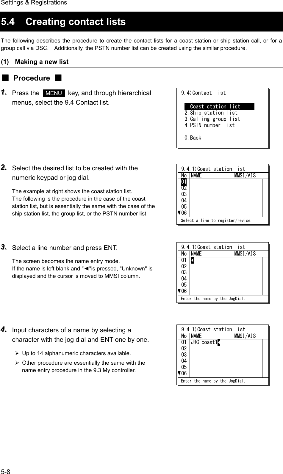
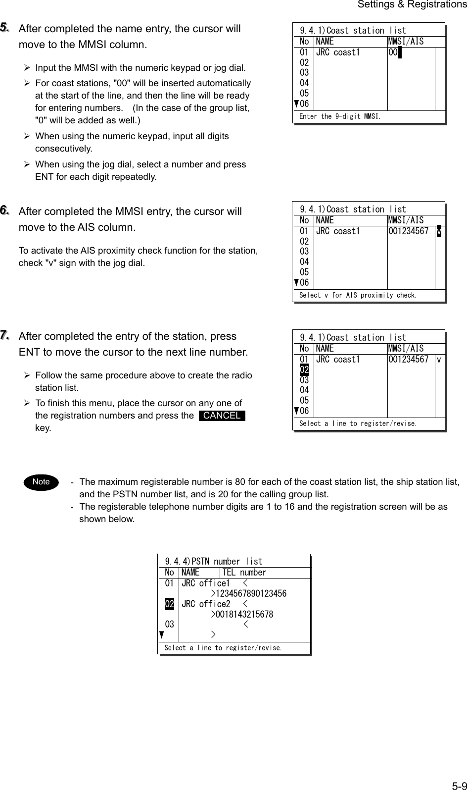
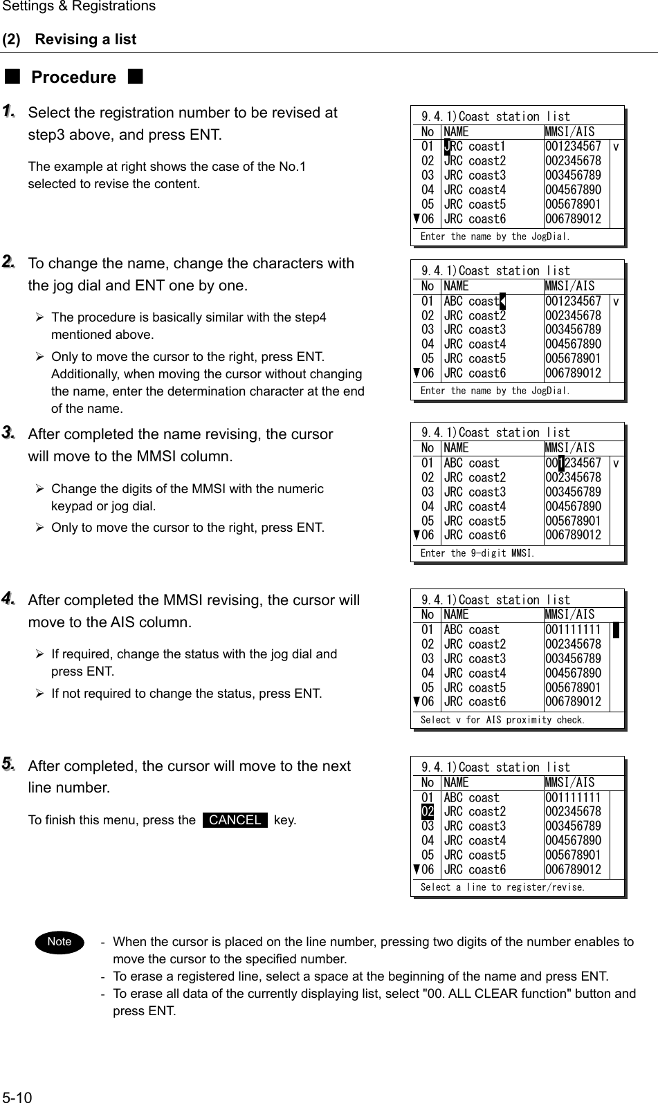
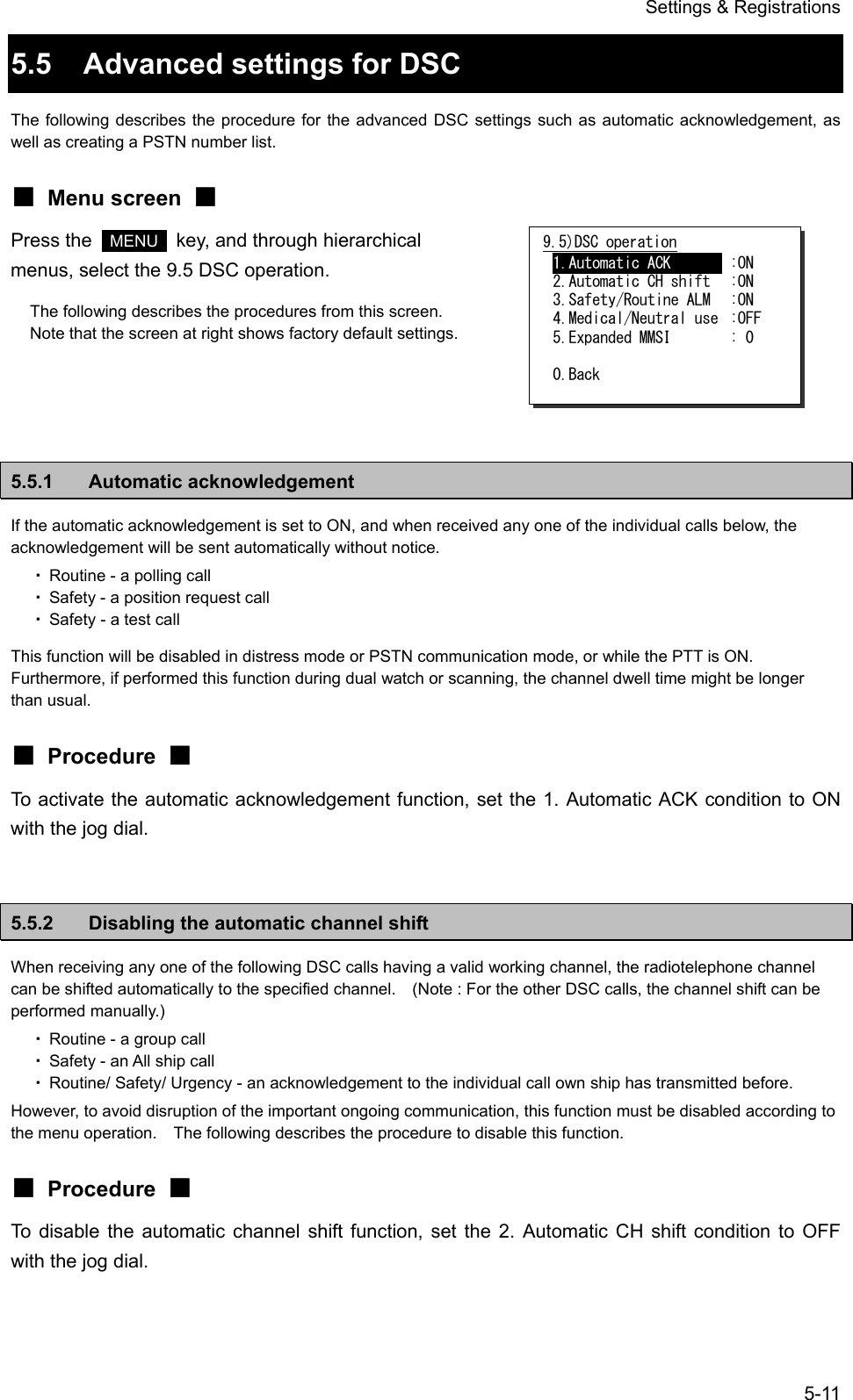
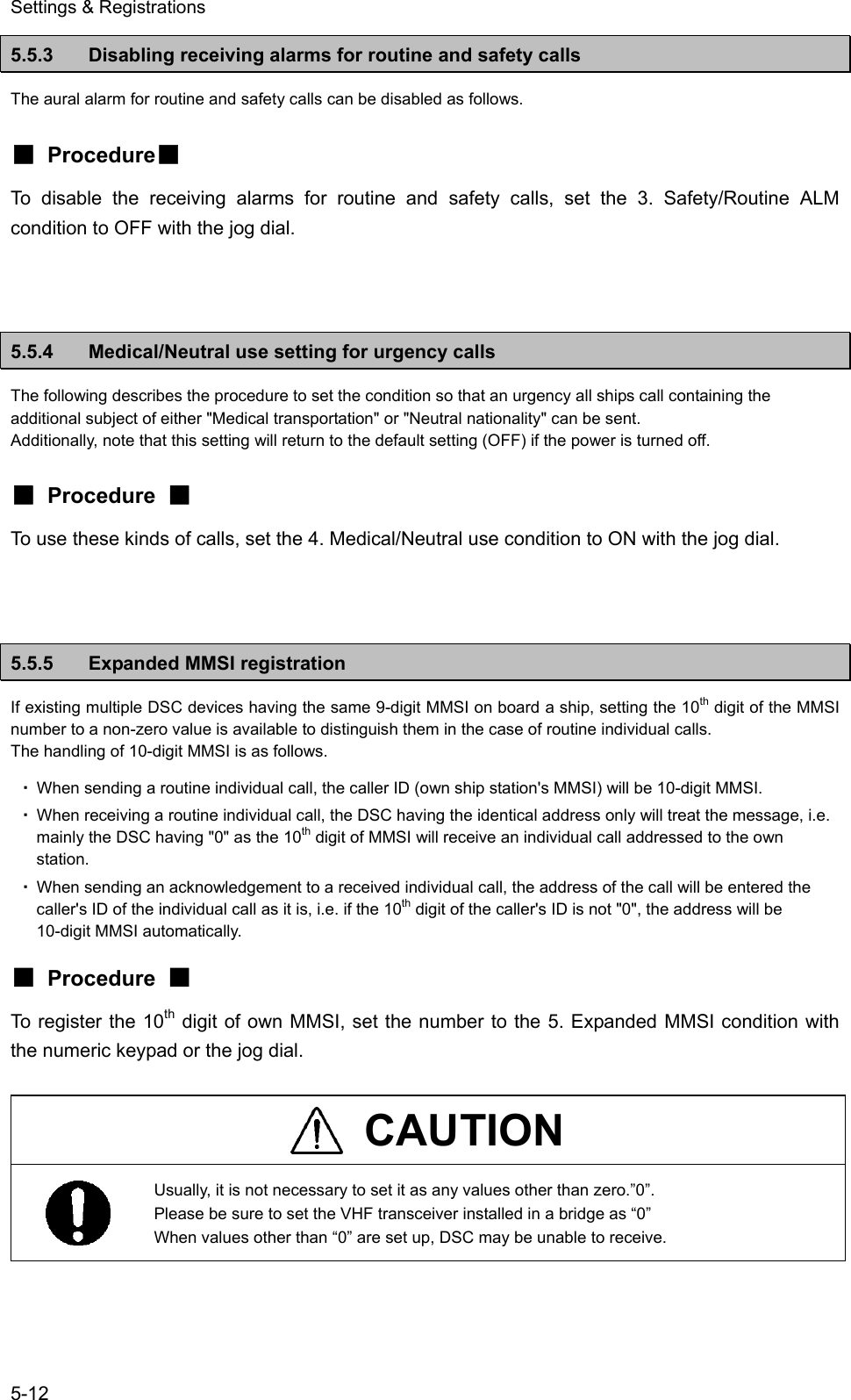
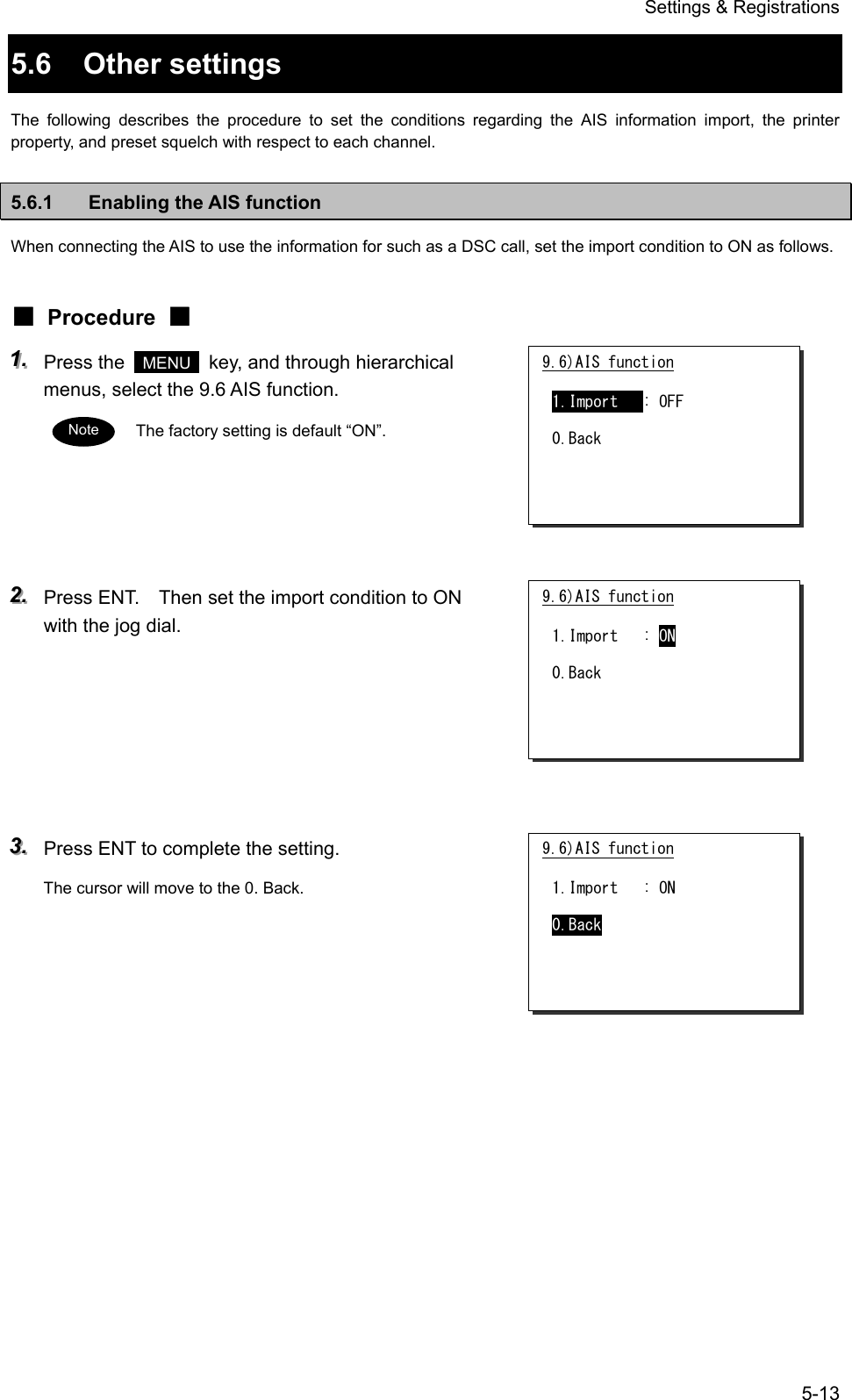
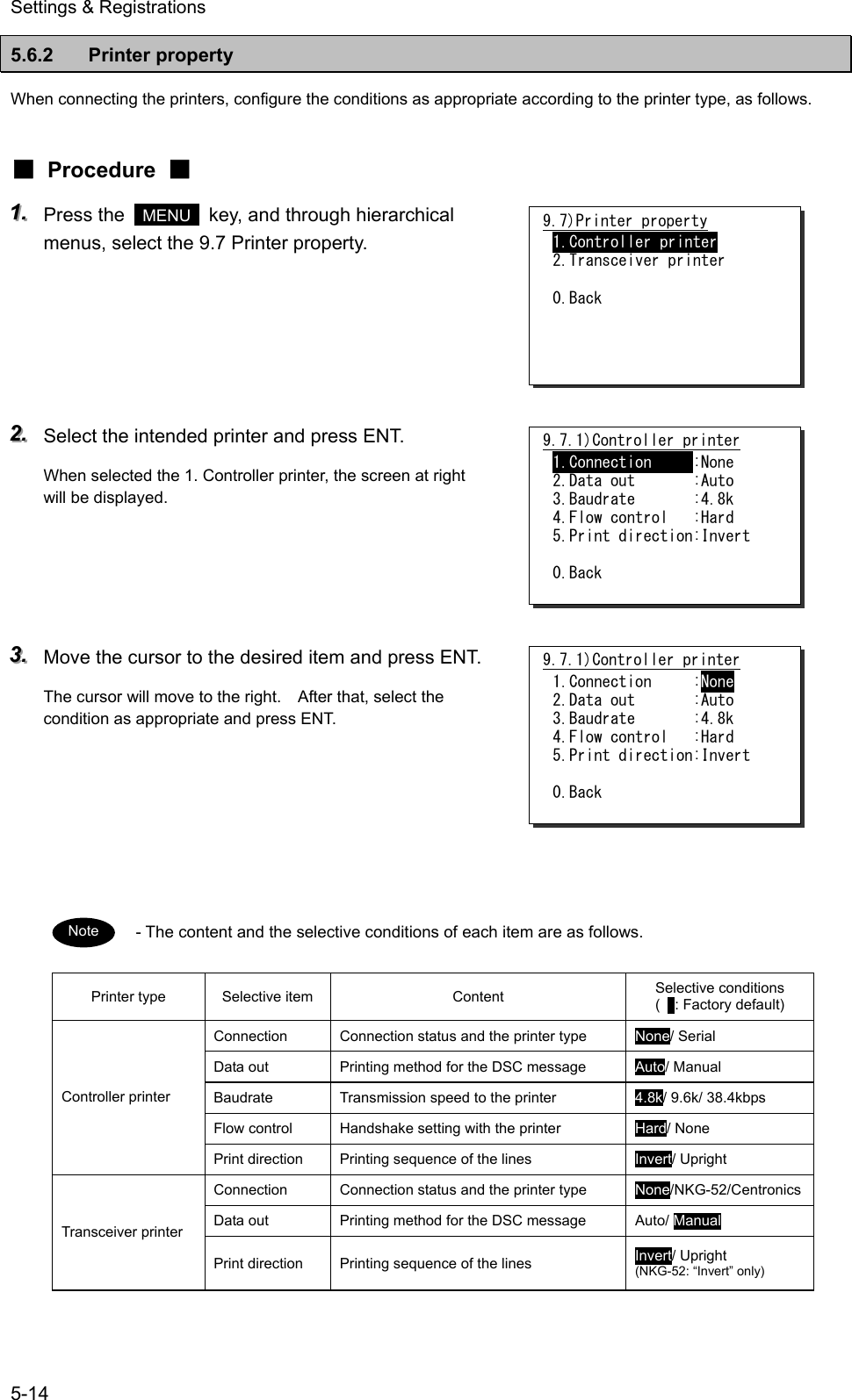
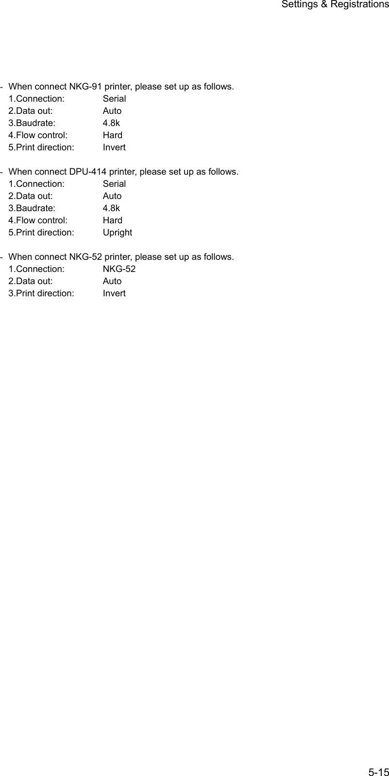

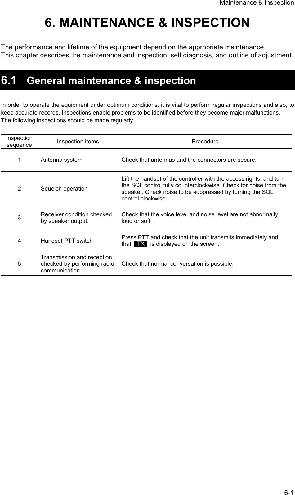
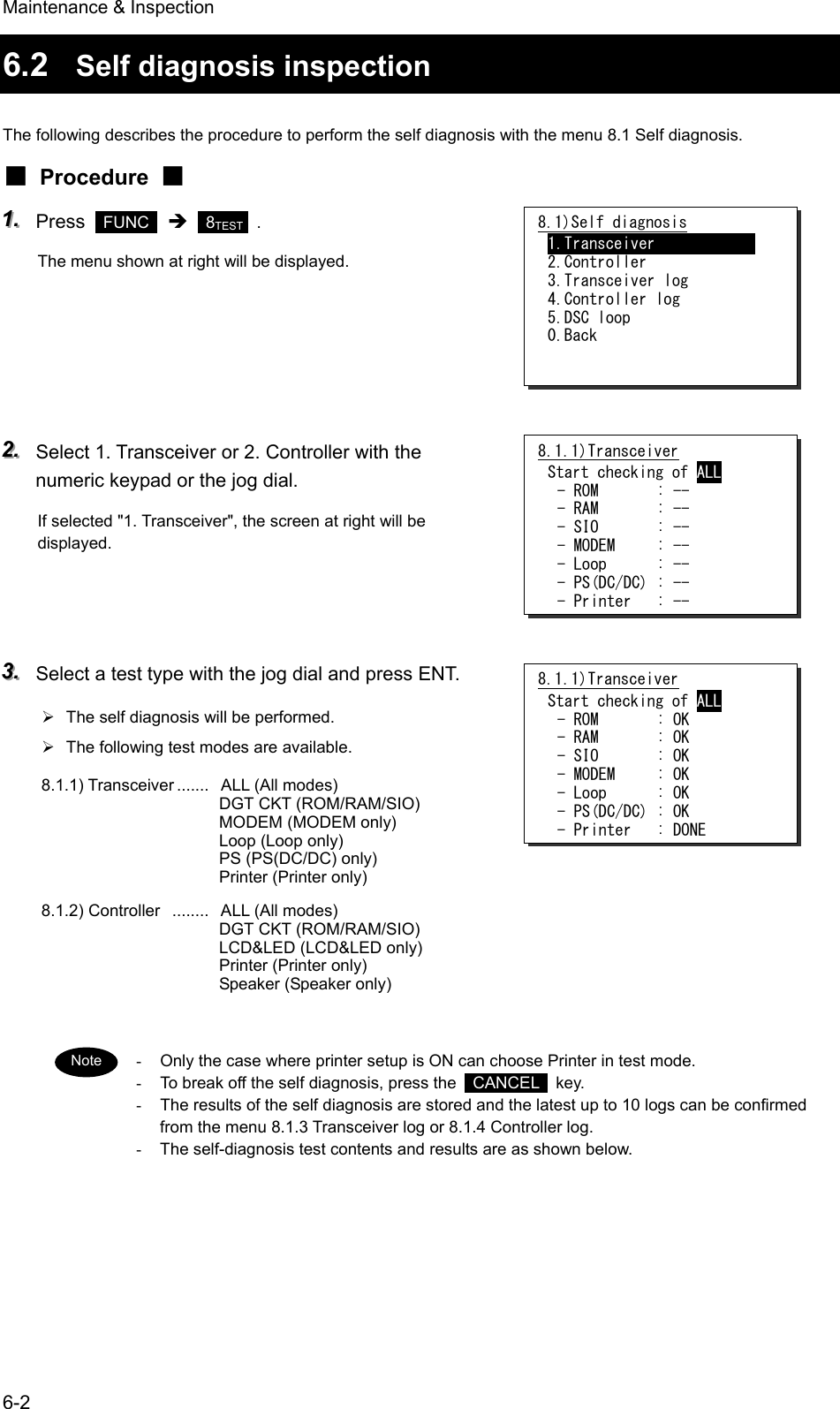
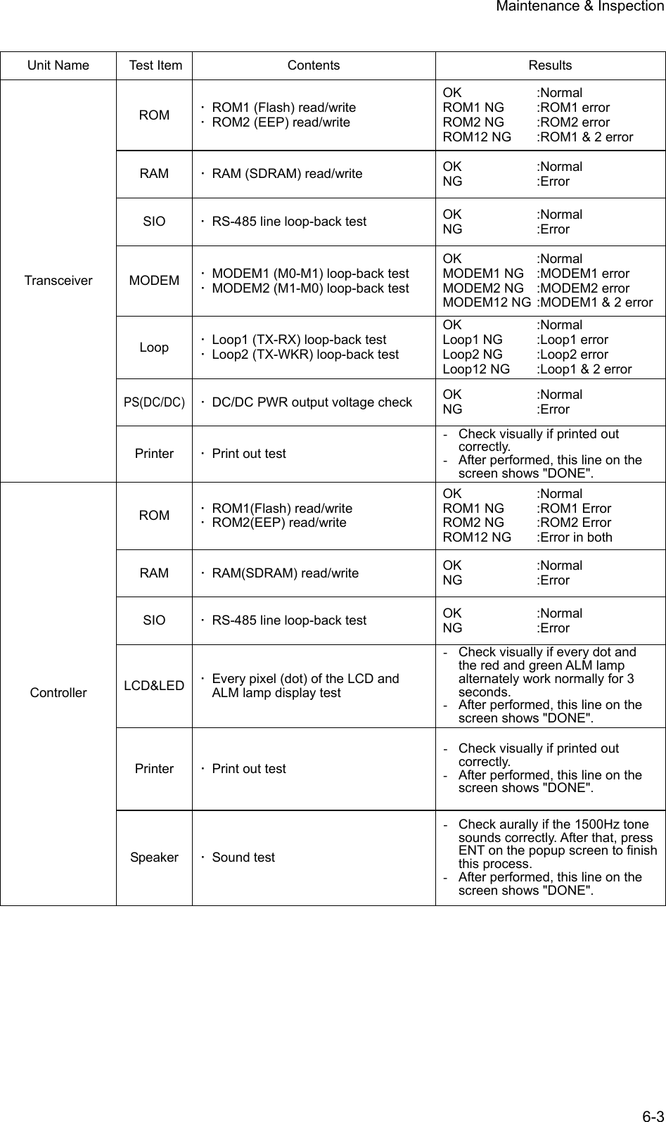
![Maintenance & Inspection 6-4 6.3 System alarm indication If detected errors regarding the equipment, the screen shows the alarm information as follows. - According to the alarm type, some features and functions may be automatically restricted. The alarm information is formatted as follows. [Alarm Date and Time] [Alarm Number], [Popup Information] - To return to the previous screen, press the CANCEL key. - When occurring 002.TX PLL unlock alarm or 003.RX PLL unlock alarm, a blinking UNLOCK mark will be additionally indicated. In this case, that mark will be remained as shown below until restored to the normal condition. Note Alarm information '06-12-31 23:59 001,TRCVR high temp 004,WKR PLL unlockStation1 TIME 23:59(UTC)16CH70CH [ITU]Station1 TIME 23:59(UTC) POS 89゚59'S EXT 179゚59'W16CHSQLCH70CHSW[ITU]UNLOCK](https://usermanual.wiki/Japan-Radio/JHS-780D/User-Guide-999383-Page-132.png)
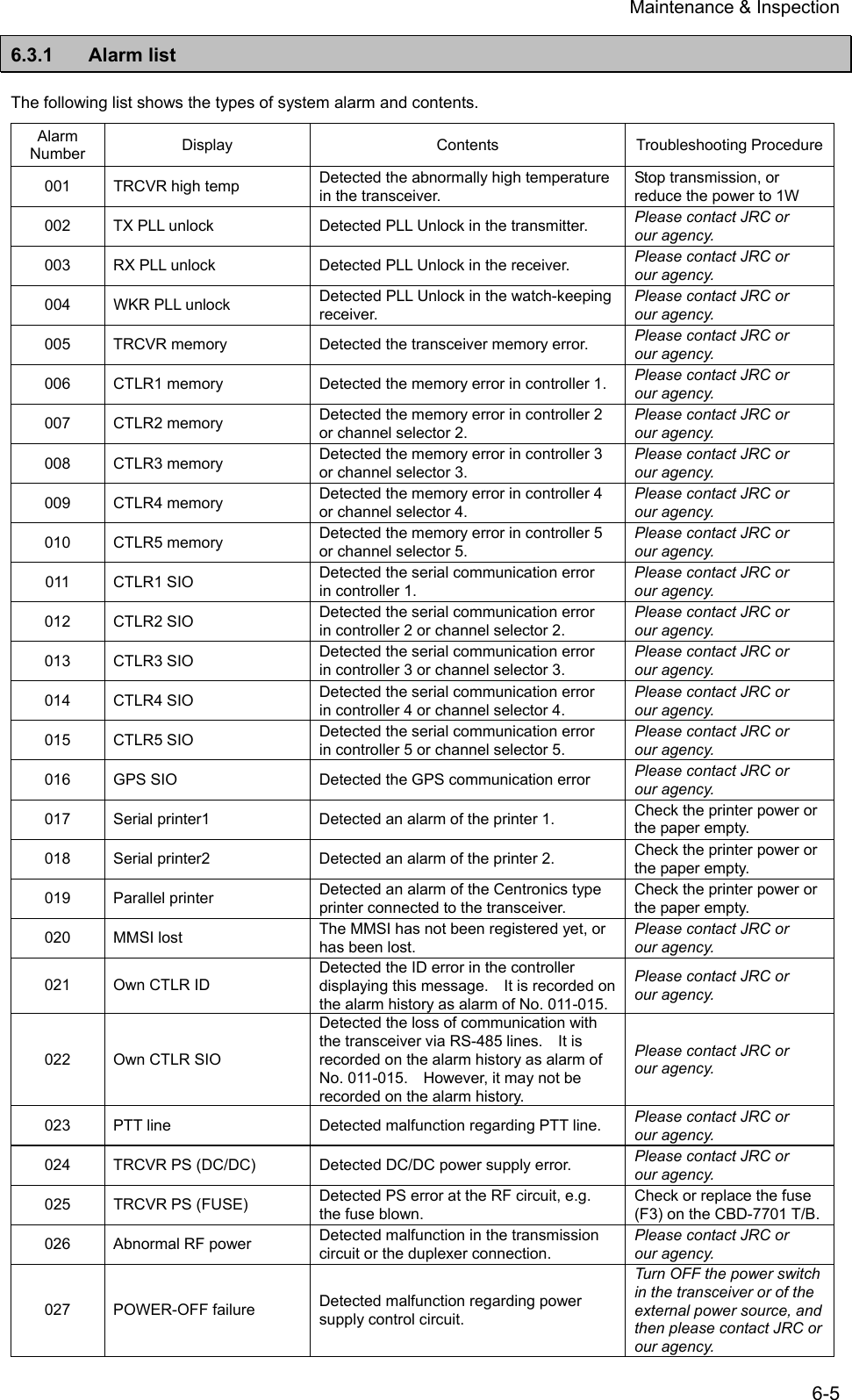
![Maintenance & Inspection 6-6 6.3.2 Viewing the alarm history The following describes the procedure to confirm the current alarm condition or the alarms occurred in past time. ■ Procedure ■ 111... Press the MENU key, and through hierarchical menus, select the 8.2 Alarm information. According to the alarm occurring condition, the screen will be displayed as shown at right. The displayed alarm information is formatted as follows. [Alarm Number], [Popup Information] 222... To check the alarm history, press ENT. After the popup screen at right will be displayed, select OK. 333... The alarm history will be displayed. The latest up to 10 histories are stored. If necessary, scroll with the jog dial. The displayed alarm history is formatted as follows. [Number] [Alarm and Recovery Date and Time] [Alarm Number] [A: Alarm/V: Recovery] [Popup Information] 8.2)Alarm information No data Press ENT to view alarm history. 8.2)Alarm information '06-12-31 23:59 001,TRCVR high temp 004,WKR PLL unlock Press ENT to view alarm history. View alarm history? [ OK ] [Cancel] Alarm history 1.'06-12-31 23:59 001 A TRCVR high temp 2.'06-12-31 23:59 004 A WKR PLL unlock 3.'06-11-25 06:33 000 V TRCVR VSWR Note Note 8.2)Alarm information 001,TRCVR high temp 004,WKR PLL unlock Press ENT to view alarm history. (In the case of alarms occurring) (In the case of no current alarm)](https://usermanual.wiki/Japan-Radio/JHS-780D/User-Guide-999383-Page-134.png)
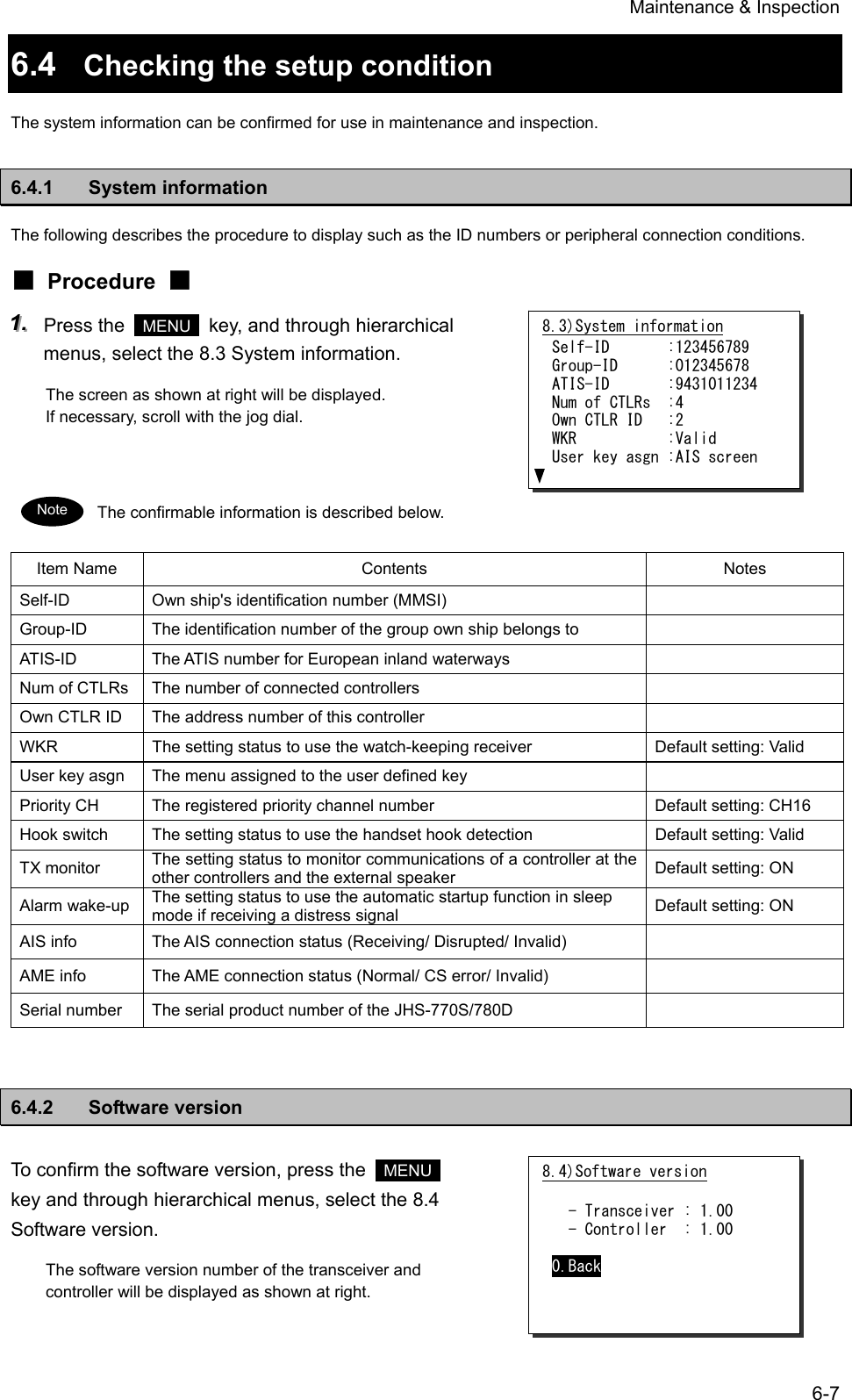
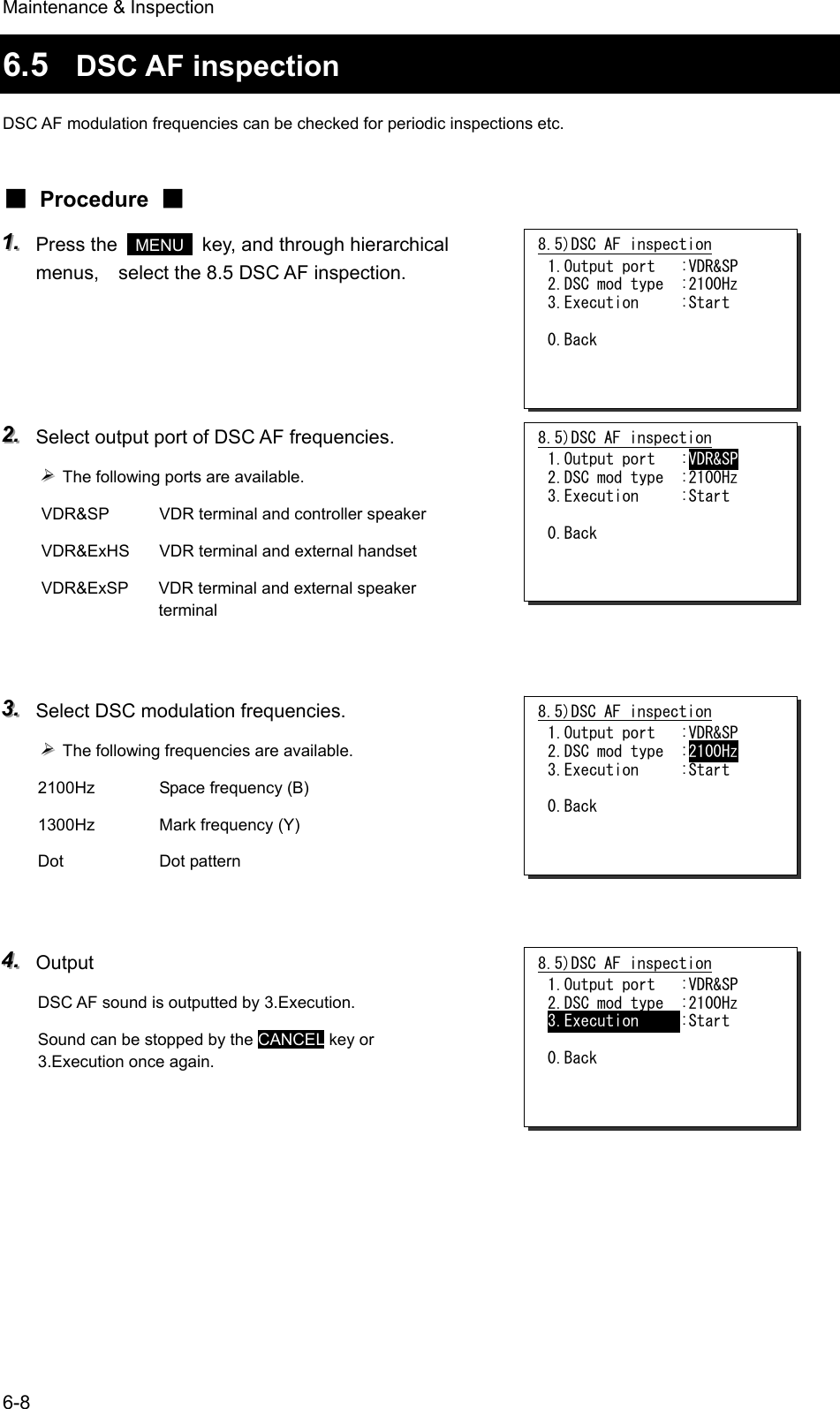
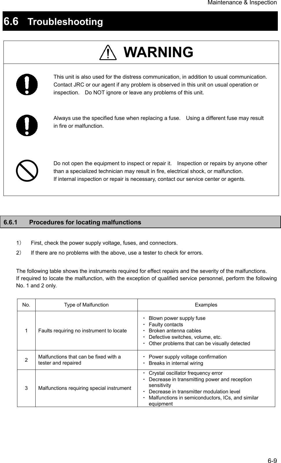
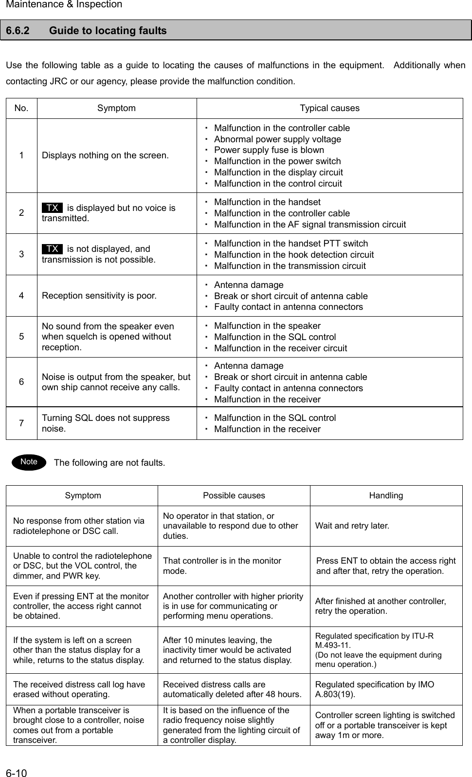
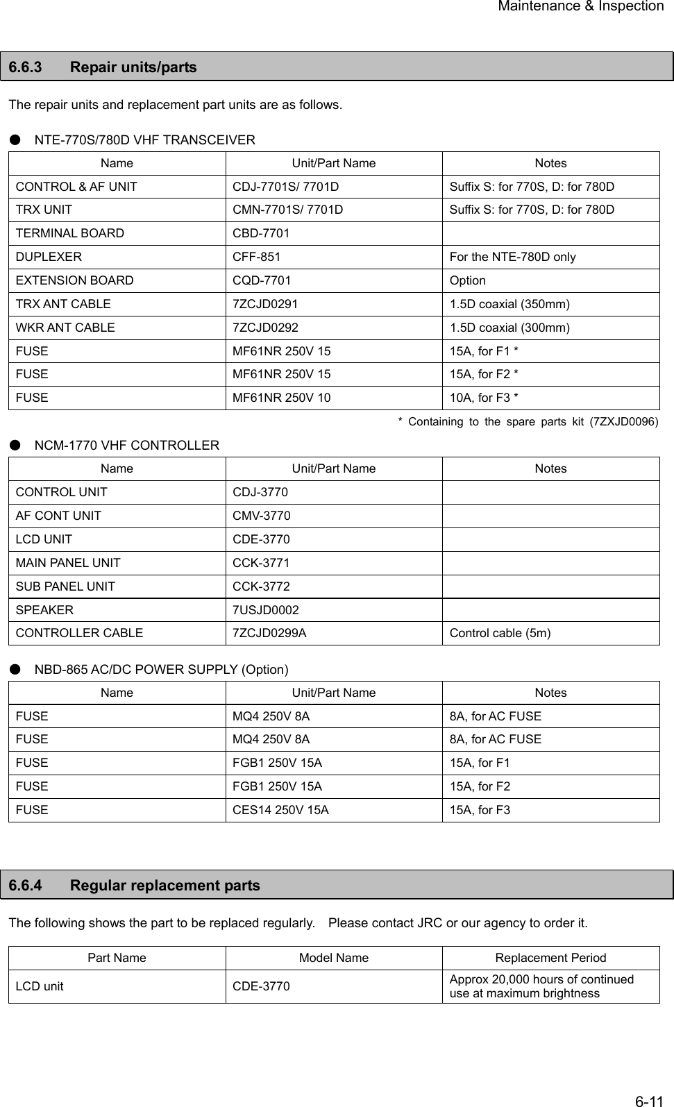
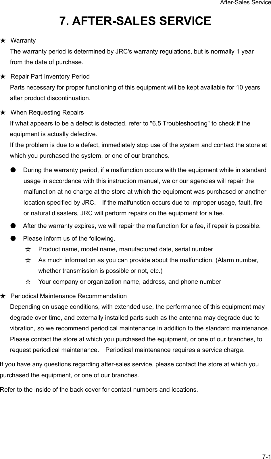
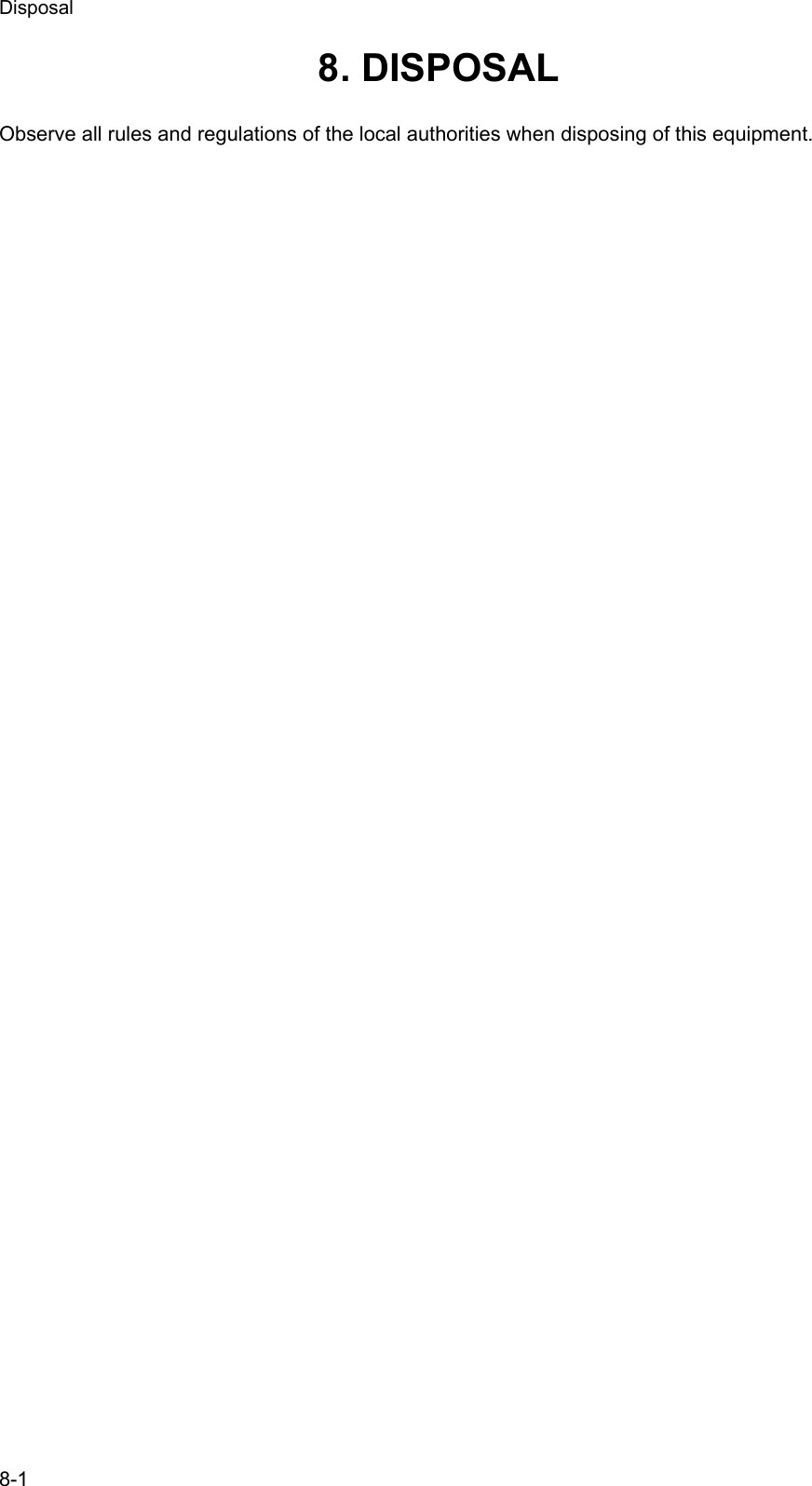
![Specifications 9-1 9. SPECIFICATIONS 9.1 JHS-770S/780D Marine VHF Radiotelephone ● General Specifications Transmission frequency Simplex/ semi-duplex: 155.000 - 163.500MHz Duplex (JHS-780D) : 156.025 - 157.425MHz Reception frequency Simplex/ semi-duplex: 155.000 - 163.500MHz Duplex (JHS-780D) : 160.625 - 162.025MHz Number of channels ITU/USA/Canada/IWW channels: Maximum 57 ch Weather channels: 10ch Private channels: Maximum 200ch Memory channels: Maximum 10ch Channel spacing 25kHz Communication modes Simplex , semi-duplex and duplex (JHS-780D) / press talk Type of emission Radiotelephone communications: F3E (G3E) DSC/ATIS: F2B (G2B) Antenna impedance 50 unbalanced Transmission/reception switching interval 300 ms or less Channel switching interval 5 sec or less Interface IEC61162-1 (GPS/AME/RMS) IEC61162-2 (AIS) 600 balanced (VDR), 600 imbalanced (Ext SP) Main controls DSC call transmission (sending and receiving), communication channel settings, transmission power settings, squelch adjustment, volume adjustment, screen adjustment Power supply voltage 24VDC (21.6VDC - 31.2VDC) Current consumption 25W transmission: Maximum 8.0A Reception: Maximum 5.0A Operating temperature range -15°C - +55°C (for full performance: 0°C - +40°C ) Storage temperature range -15°C - +55°C Humidity resistance No abnormality after standing 4 hours in +40ºC, 93% RH Vibration resistance (3 Axis) 5Hz – 12.5Hz: Full amplitude 3.2mm 12.5Hz – 25Hz: Full amplitude 0.8mm 25Hz – 50Hz: Full amplitude 0.2mm No abnormality after vibration for 15 minutes in each axis No abnormality after testing resonance points for 30 minutes Continuous operation (Phone) No abnormality after operating continuously for 8 hours Continuous operation (DSC, WKR) No abnormality after operating continuously for 24 hours Protection rating IP22 equivalent (Controller panel) Dimensions and mass Transceiver unit 240(W)x290(H)x128(D) [excluding projections] Approximately 6.3kg(NTE-770S) / 6.9kg(NTE-780D) Controller unit 230(W)x142(H)x89(D) [excluding projections], Approximately 1.3kg](https://usermanual.wiki/Japan-Radio/JHS-780D/User-Guide-999383-Page-143.png)