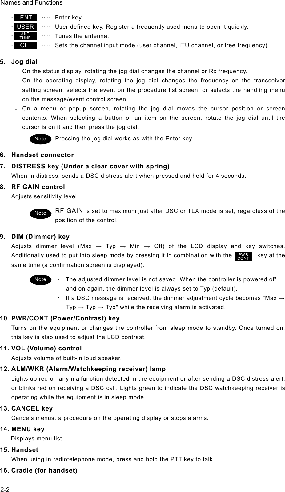
Japan Radio JSS-2250 Marine MF/HF GMDSS Radio Transceiver, digital selective calling (DSC) / narrow-band direct printing (NBDP) Modem User Manual
Japan Radio Co Ltd. Marine MF/HF GMDSS Radio Transceiver, digital selective calling (DSC) / narrow-band direct printing (NBDP) Modem
User Manual
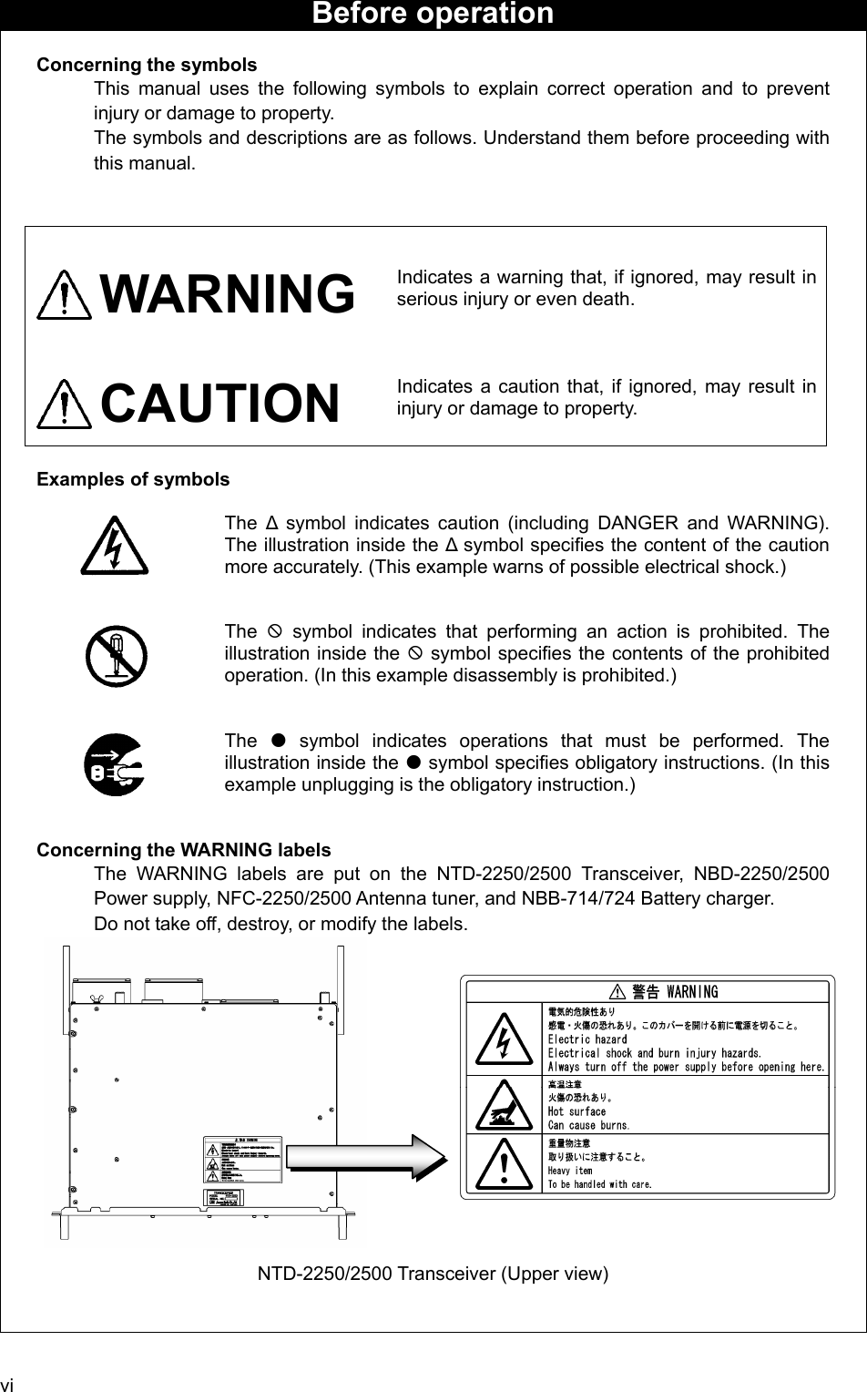
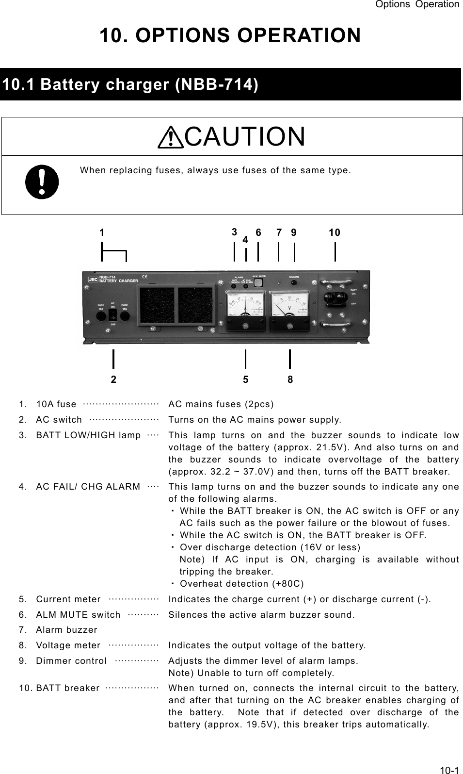
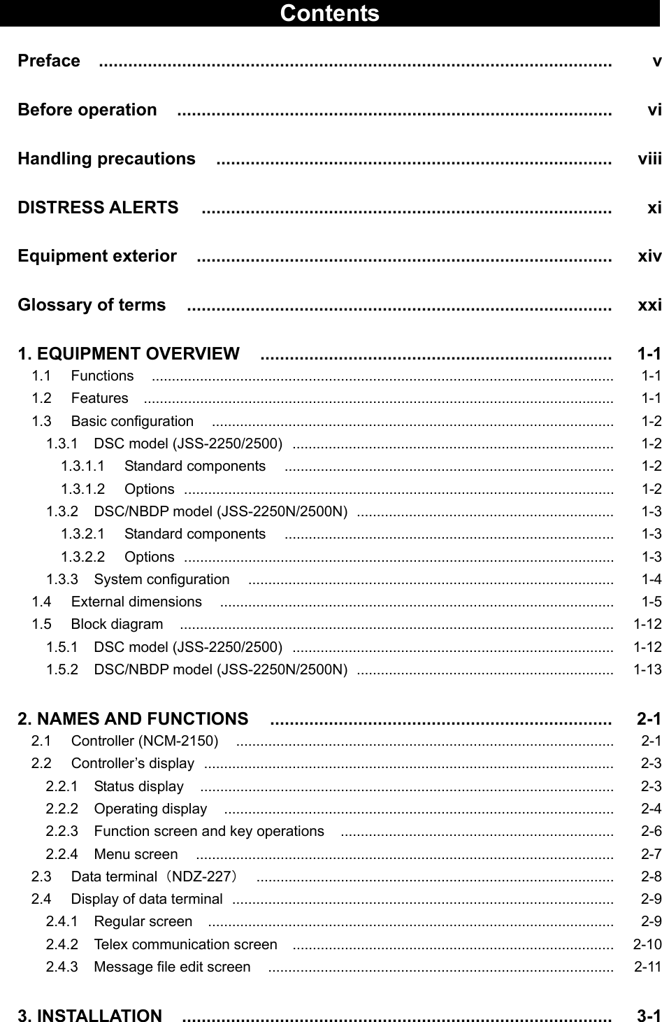
![ix CAUTION Do not use this equipment anyplace other than specified. Doing so may cause failure or malfunction. Do not turn the trimmer resistors or the trimmer capacitors on the PCB unit. Doing so may cause failure or malfunction. Do not install the equipment in a place near water or in one with excessive humidity, steam, dust, or soot. Doing so may cause fire, electrical shock, or malfunction. Do not test the distress alert. Doing so may inconvenience local shipping and rescue centers. Do not turn off the equipment when at sea because the SOLAS Convention requires keeping watch on distress and safety frequencies at all times. Always listen to 2187.5 kHz, and 8414.5 kHz, and one or more of the following frequencies; 4207.5 kHz, 6312.0 kHz, 12577.0 kHz, or 16804.5 kHz. In class B mode, it is necessary to keep watch only on 2187.5 kHz. When completely turning off the power to the equipment, turn off the breakers on the power supply. To operate DSC functions of the equipment, the ID numbers assigned to the ship must be registered in advance. If registration is necessary, contact our service center or agents. To install this equipment, contact our service center or agents. Special knowledge on selecting the place where the antenna is to be mounted and setting the ID number (MMSI) assigned to the ship is required in addition to installing the equipment. When sending a distress alert, follow the instructions of the ship's captain or officer in charge. If a false distress alert is transmitted accidentally, select the Cancel menu and transmit the distress cancel referring the guidance displayed on the controller. And then report the false distress alert to a nearby RCC (Rescue Coordination Center/ in Japan, inform the nearest Japan Coast Guard.) Information to be reported: Ship's name, type, nationality, and ID number, the date/time, location and reason why the false distress alert was transmitted. Also the unit model name and manufacture number/date, if possible. To turn off an alarm or clear a display such as a received DSC message, do not press the DISTRESS key. Doing so may cause a false distress alert. (Press the CANCEL key to turn off the alarm.) When sending a drobose call, do NOT press the DISTRESS key. Doing so may cause a false distress alert. (Drobose calls can be sent via the [Call] button displayed on the screen.) A distress acknowledgement or a distress relay call can be transmitted using the option on an active procedure screen, but when sending such a call, follow the instructions of the ship's captain or officer in charge.](https://usermanual.wiki/Japan-Radio/JSS-2250/User-Guide-2169640-Page-11.png)
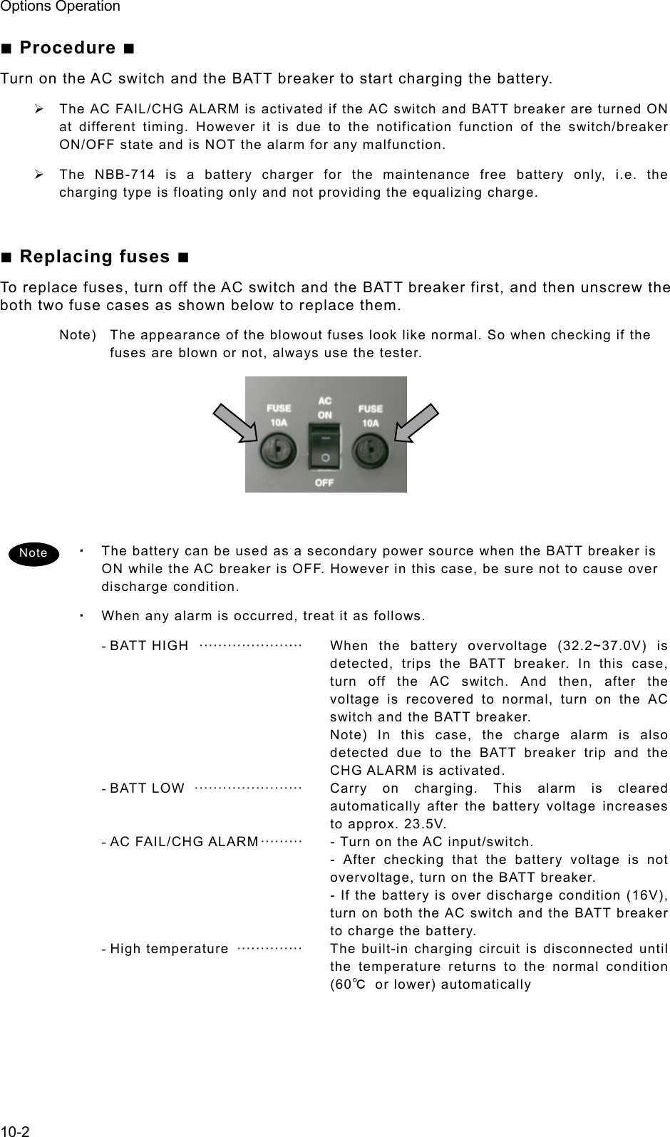
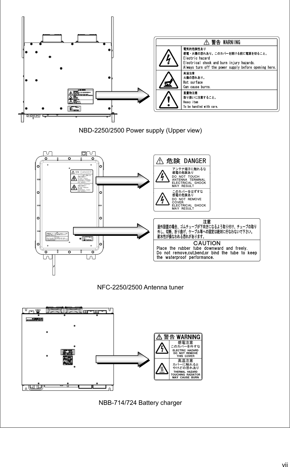
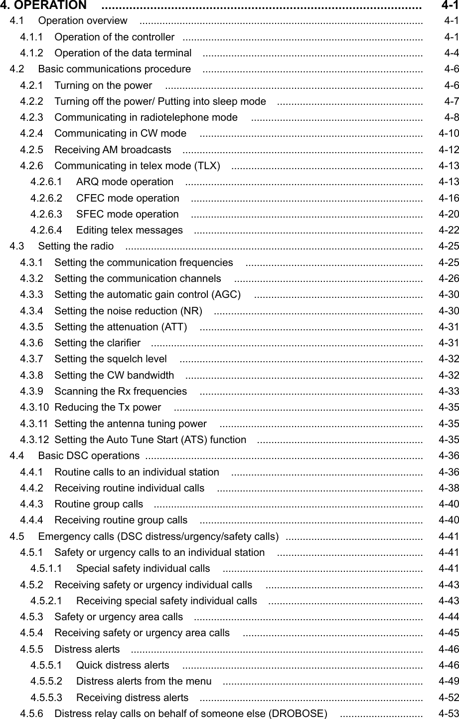
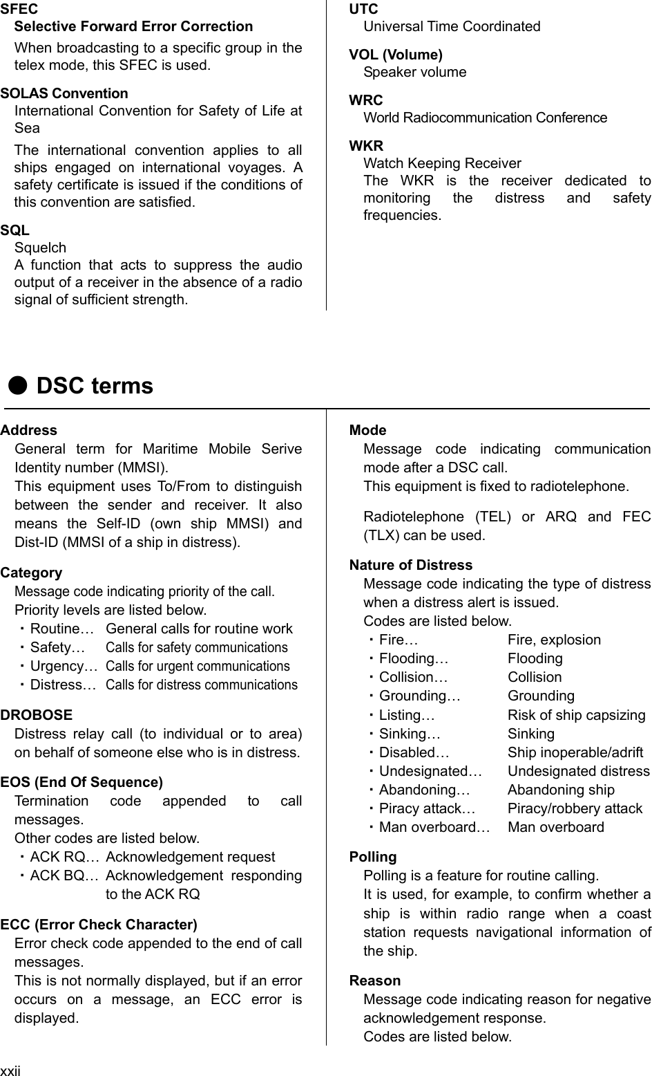
![xi Sending a Distress Alert CAUTION When sending a distress alert, follow the instructions of the ship's captain or officer in charge. 111... Open the DISTRESS key cover on the NCM-2150 MF/HF CONTROLLER. 222... Press and hold the DISTRESS key for 4 seconds to send the distress alert. When the countdown is finished the screen below on the right is displayed, and after antenna tuning the distress alerts are transmitted. 333... After sending the distress alert, wait for an acknowledgement. The radiotelephone can be used to communicate even while waiting for an acknowledgement on the screen below left. When an acknowledgement is received, press the CANCEL key or ENT to cancel the alarm on the below right screen, and communicate with the station. Unless an acknowledgement is received or the distress alert is cancelled manually, the equipment repeats the distress alert every 3.5 to 4.5 minutes. DDDIIISSSTTTRRREEESSSSSS AAALLLEEERRRTTTSSS TEL ITU- 401 4357.0 4065.0RX kHzTX kHzNonDST: +DROBOS: +EdtDST: +ID 431001234 23:59(UTC)Pos 89゚59.0123'N 179゚59.6789'E@23:59 (EXT)SIGWKR scan bands:2 4 6 8 12 16MHz Distress call starts in sec4ID 431001234 23:59(UTC)DSC Rx: 2187.5/Tx: 2187.5kHzDistress calling Next :--- Stage :Waiting for CH free Call-F: / / / / / Nature:Undesignated PosUTC: 89゚59.0123'N :179゚59.6789'E @23:59 Mode :Radiotelephone[Cancel]SIG WKR 2 4 6 8 12 16MHzID 431001234 23:59(UTC)TEL Rx: 8291.0/Tx: 8291.0kHzDistress calling Next :Resends 4.1min later Stage :Waiting for ACK Call-F:2/4/6/8/12/16 Nature:Undesignated PosUTC: 89゚59.0123'N :179゚59.6789'E @23:59 Mode :Radiotelephone[FRQ][Pause][POS][CHNG][Cancel]Rx: 8291.0/Tx: 8291.0kHzSIG WKR 2 4 6 8 12 16MHzTEL 2182.0 2182.0ID 431001234 23:59(UTC)Pos 89゚59.0123'N 179゚59.6789'E@23:59 (EXT)RxID:123456789|OWN D-ACK|2MHzDIST acknowledged(00.2min)Tx:2|4|6|8|12|16/Undesignated /TEL89゚59.0123'N179゚59.6789'E@23:59Press CANCEL to silence alarm.A DST ALT](https://usermanual.wiki/Japan-Radio/JSS-2250/User-Guide-2169640-Page-13.png)
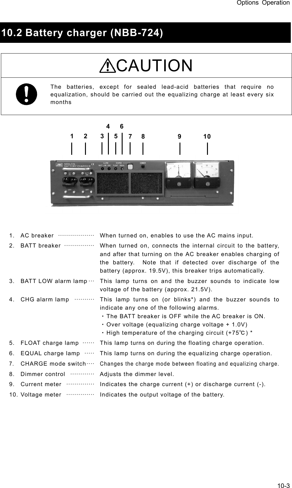
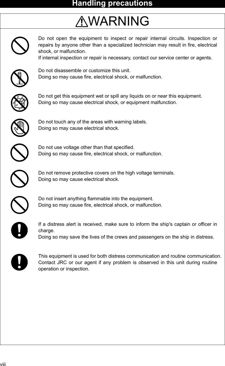
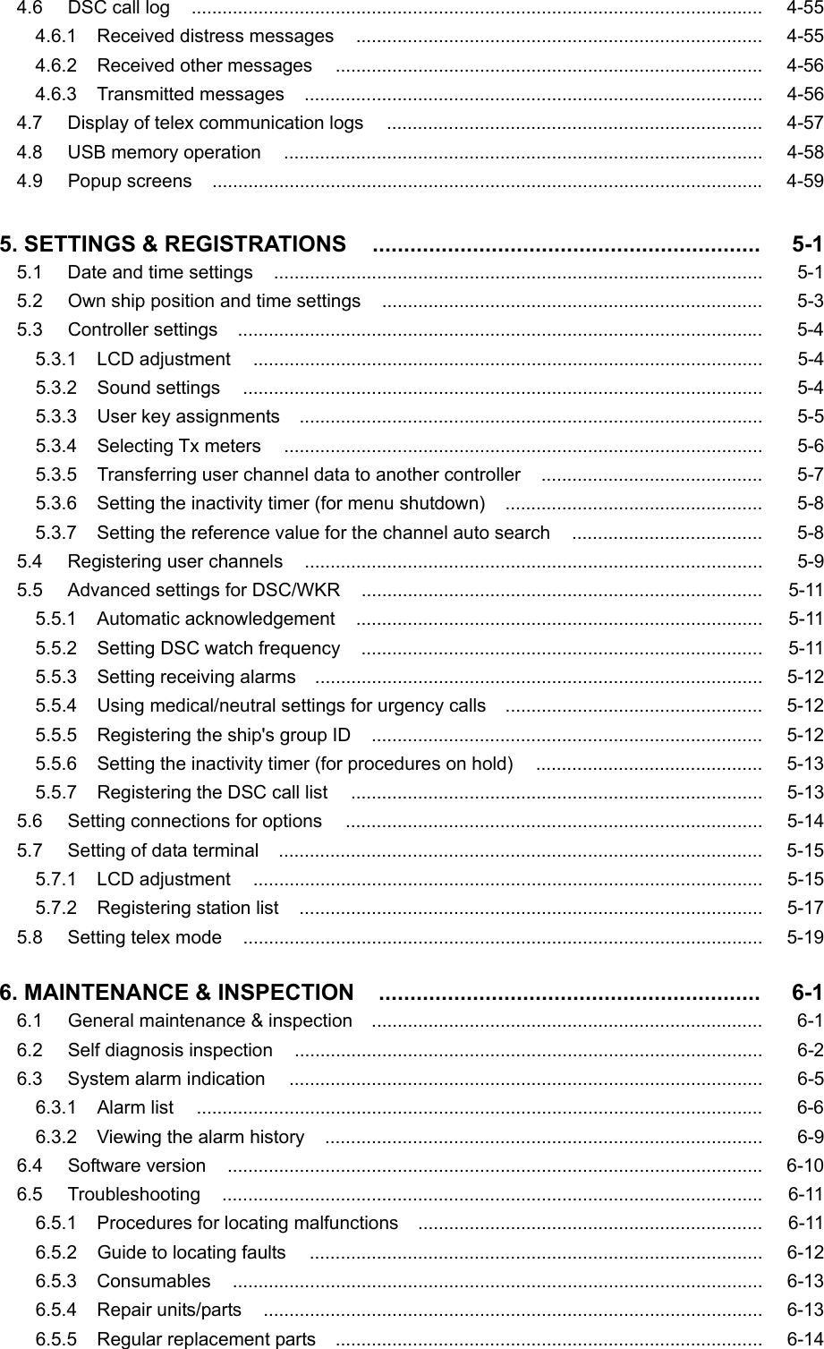
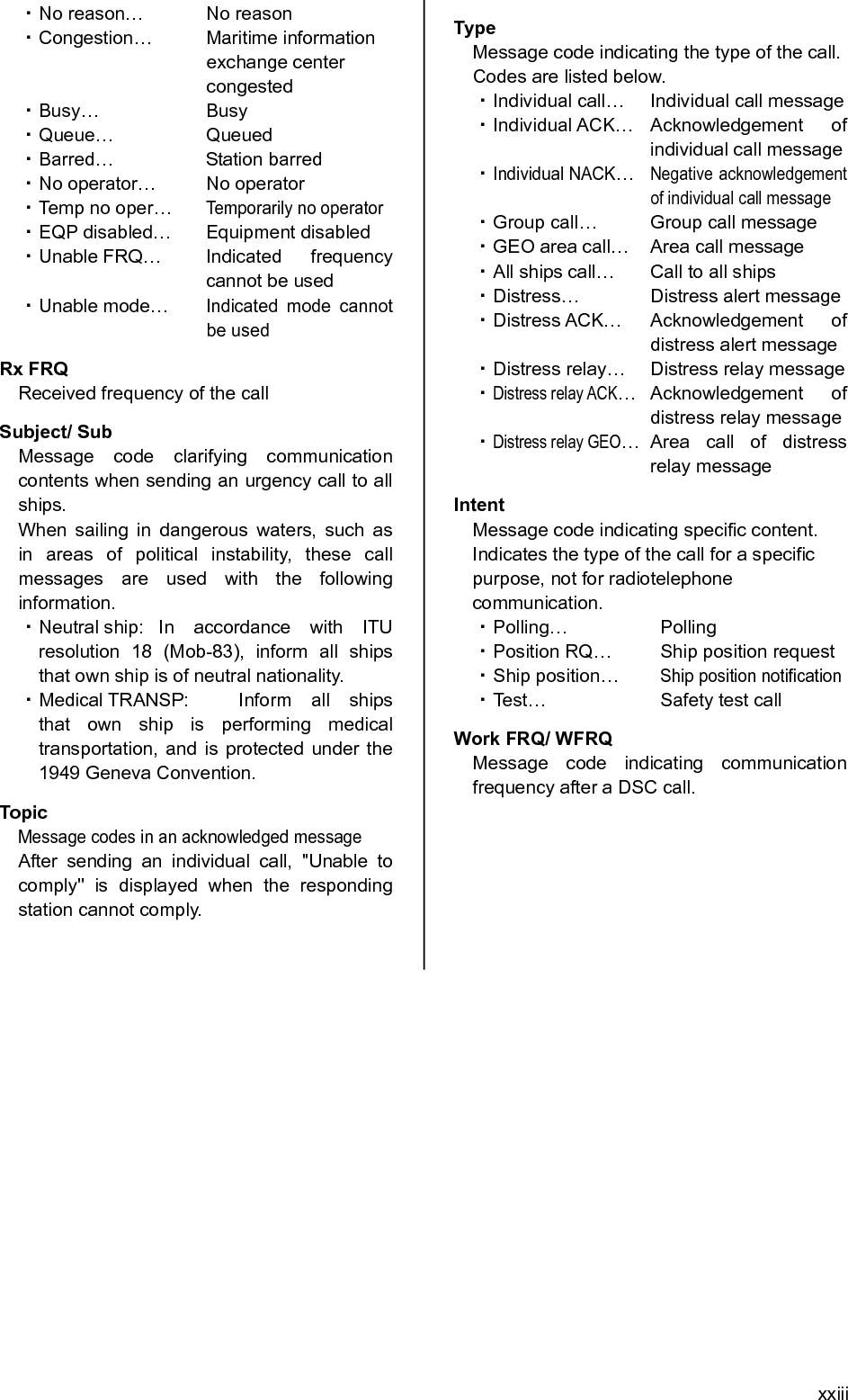
![xii 444... After receiving acknowledgement, use the radiotelephone to request rescue. First, the responding station calls by radiotelephone. Communicate the following information to that station. z Say "MAYDAY". z Say "This is (name of your ship)". z Tell the station the ship's Maritime Mobile Service Identity (MMSI) number, call sign, ship's position, nature of distress, and rescue requests. If time permits, enter the nature of the distress or the mode (Radiotelephone or FEC) as follows, just before sending the distress alert. (For more details, see 4.5.5 Distress alerts.) 1) Open menu 3. Editing a distress msg. 2) Press ENT on the screen at right and select the nature of the distress. 3) Press ENT to confirm the selection. The nature of the distress is set. If the position and time (UTC) are not displayed automatically for any reason, input them manually at this time. 4) Press and hold the DISTRESS key for 4 seconds to send the distress alert. The rest of the procedure is the same as described above. Terminating a Distress Alert CAUTION If a false distress alert is transmitted accidentally, select the Cancel menu and transmit the distress cancel referring the guidance displayed on the controller. And then report the false distress alert to a nearby RCC (Rescue Coordination Center/ in Japan, inform the nearest Japan Coast Guard.) Information to be reported: Ship's name, type, nationality, and ID number, the date/time, location and reason why the false distress alert was transmitted. Also the unit model name and manufacture number/date, if possible. Select the Cancel menu and press ENT on the NCM-2150 MF/HF CONTROLLER. The screen shown below is displayed. Then select Continue with the jog dial and press ENT to start the distress cancel procedure referring the guidance displayed on the controller. Note) For more details, see the description in the 4.5.5.1 Quick distress alerts. Note ID 431001234 23:59(UTC)Pos 89゚59.0123'N 179゚59.6789'E@23:59 (EXT)TEL Rx: 4146.0/Tx: 4146.0kHz3)Editing a distress msg Nature :[Undesignated ] Position :[NE] [ 89゚59.0123'N] [179゚59.6789'E] UTC of pos :[23:59] Mode :[Radiotelephone] Attempt type:[Multi-FRQ ] Tx bands :[2/4/6/8/12/16] [Preview] [Tips] [Cancel]NatureID 431001234 23:59(UTC)TEL Rx: 2182.0/Tx: 2182.0kHzDistress calling Next :Resends 3.2min later Stage :Waiting for ACK Call-F:2/4/6/8/12/16 Nature:Undesignated PosUTC: 89゚59.0123'N :179゚59.6789'E @23:59 Mode :Radiotelephone[FRQ][Pause][POS][CHNG][Cancel][Cancel] !!Warning!! Cancel the transmitted false distress alert? (TGT: 2/4/6/8/12/16M) [Continue] [Return][Return]SIG WKR 2 4 6 8 12 16MHz](https://usermanual.wiki/Japan-Radio/JSS-2250/User-Guide-2169640-Page-14.png)
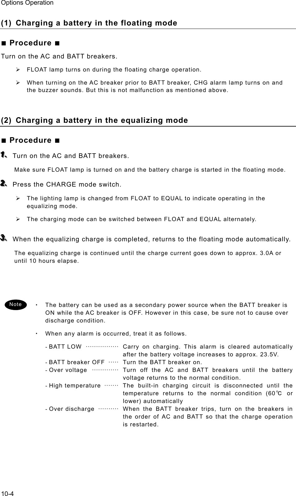
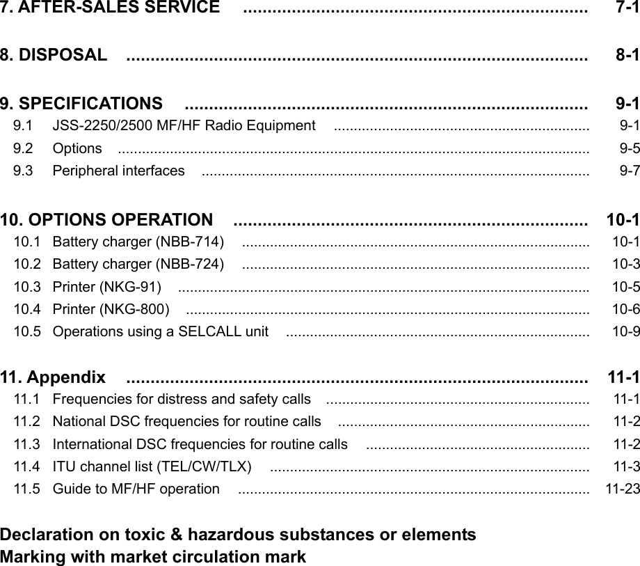
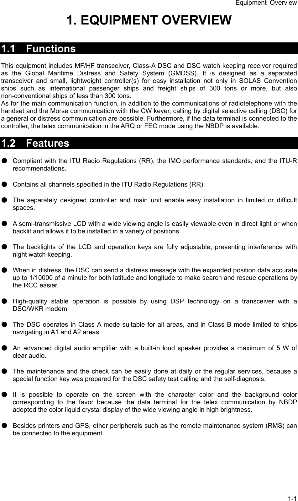
![xiii Receiving a Distress Alert WARNING If a distress alert is received, make sure to inform the ship's captain or officer in charge. Doing so may save the lives of the crew and passengers on the ship in distress. 111... When a distress alert is received, the information such as the ID number of the ship in distress and the stage of the distress event are displayed. If the equipment is not used, i.e. there is no active procedure at that time, a distress and safety frequency is set and the ALM lamp starts blinking, and an alarm gradually grows louder. 222... Press the CANCEL key to stop the alarm. If the popup screen is shown, select "Accept" and press ENT. After the specified communicate mode and the distress frequency are set, keep watch under such a condition. Keep watch for five minutes or more, and executes the report to the coast station etc. as appropriate 333... To acknowledge to the distress alert after coordination with the coast station, from the above right screen, press FUNC key to move the active screen to the message control area. Then select ACK with jog dial and press ENT to send the acknowledgement. After acknowledging the distress alert, communicate with the ship in distress as follows; z Say "MAYDAY". z Repeat the identity (MMSI) of the ship in distress 3 times z Say, "This is". z Repeat the identity (MMSI) of your ship 3 times z Say "RECEIVED MAYDAY". TEL 8291.0 8291.0ID 431001234 23:59(UTC)Pos 89゚59.0123'N 179゚59.6789'E@23:59 (EXT)RxID:123456789|DISTRESS ALTWaiting to send ACK(00.6min)Multi-FRQ:2/ / /8/ /16TEL :Rx 8291.0/Tx 8291.0KHz[ACK][RLY][INF][FRQ][HLD][END]A DST ALTTEL 2182.0 2182.0ID 431001234 23:59(UTC)Pos 89゚59.0123'N 179゚59.6789'E@23:59 (EXT)A R:DST ALTA R:DST ALT RxFR:123456789|DISTRESS ALT Waiting to send ACK(00.2min)Single-FRQ: 2187.5kHzTEL :Rx 2182.0/Tx 2182.0kHz[ACK][RLY][INF][FRQ][HLD][END]SAME DST ON ANOTHER FRQ From :123456789 Work-F : 8291.0kHz EQP will tune to the above FRQ within 10s. [Accept] [Ignore][Accept]](https://usermanual.wiki/Japan-Radio/JSS-2250/User-Guide-2169640-Page-15.png)


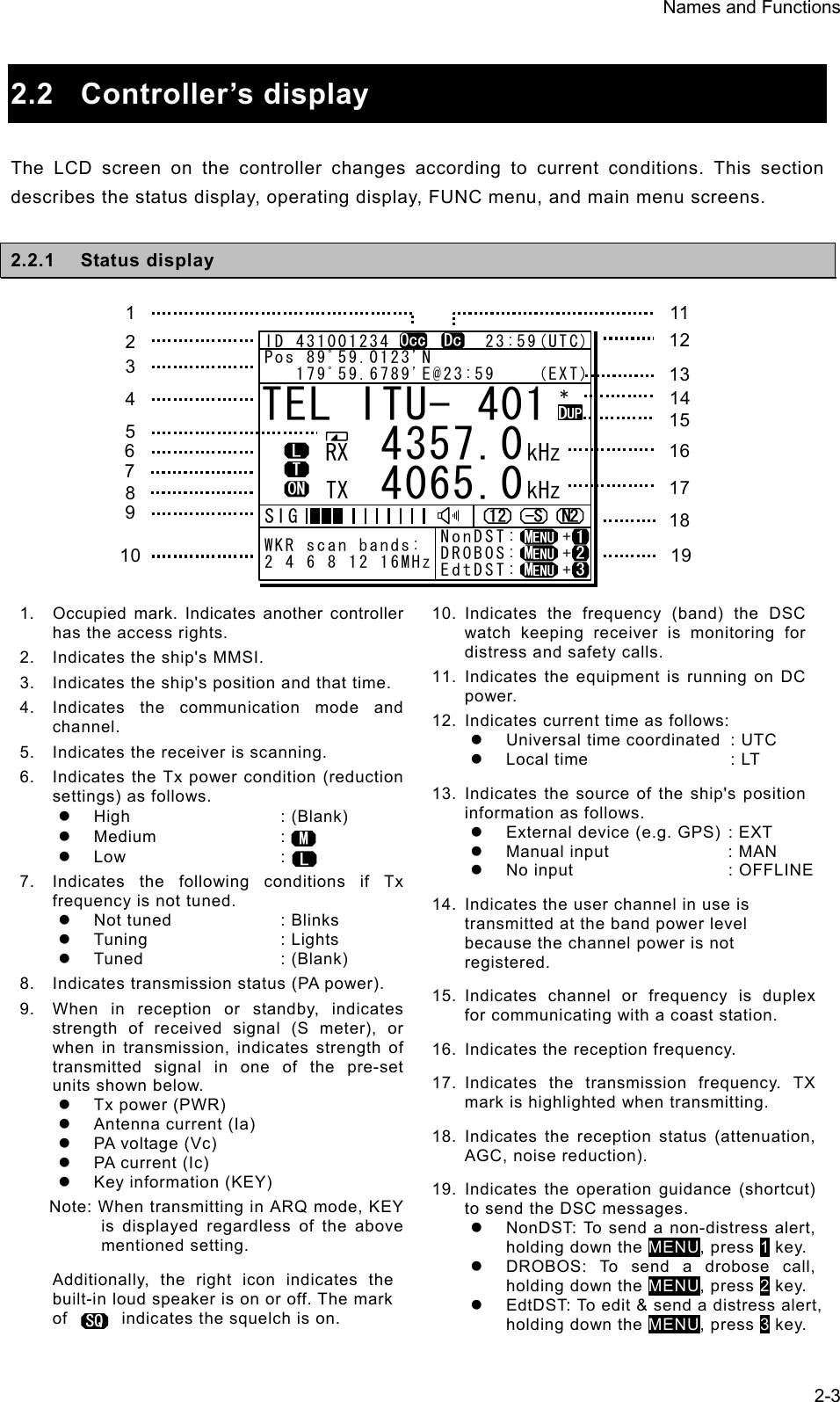
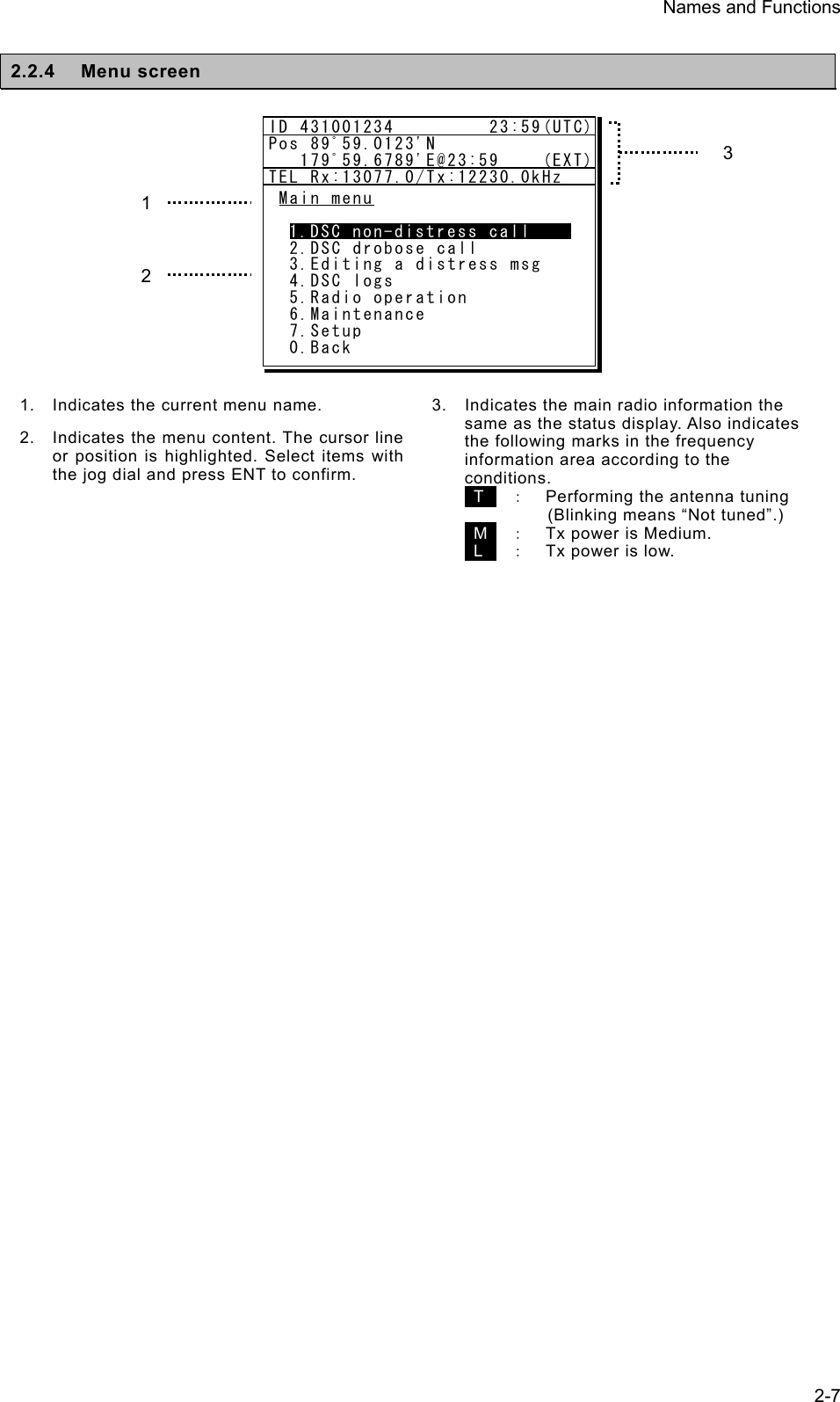
![Names and Functions 2-42.2.2 Operating display (1) General After setting the frequency, pressing PTT key in TEL mode, sending/receiving messages in DSC/TLX mode, and things like that, the controller shows the operating display as follows. 1. Indicates the MMSI and the latest position and that time. 2. Indicates an focused screen with sign and thick-frame, i.e. the operating display is divided into three screens as below, where the focused screen can be moved using the FUNC key for clockwise. 3. Indicates the transceiver setting screen similar to the status display. Icons on this area are as follows. z Scanning : z Not tuned yet : z Tx power reduction : z Turned the PA ON : z Attenuation (dB) : z AGC (Fast/ Slow) : z Noise reduction (NR1/NR2/BC) : 4. Indicates the S meter and watchkeeping receiver monitoring frequencies mentioned above. 5. Indicates the existing procedures. If the procedure is under operation (active), A mark is added in the box frame. Further, if other procedures on hold exist, they are indicated in the other box frames and are selectable to operate at any time. And while this screen is focused, the turning dial animation is shown as below. 6. Indicates the content and the handling menus of the procedure located at the top of the procedure list screen. During operating an active procedure, any functions such like the DSC automatic acknowledgement become invalid to avoid the ongoing communication interruption. ID 431001234 23:59(UTC)Pos 89゚59.0123'N 179゚59.6789'E@23:59 (EXT)Communicating on TEL Rx:13077.0/Tx:12230.0kHzTip)Use FUNC to change op area. [HLD][END]AATEL 13077.0 12230.0DUPID 431001234 23:59(UTC)Pos 89゚59.0123'N 179゚59.6789'E@23:59 (EXT)Communicating on TEL Rx:13077.0/Tx:12230.0kHzTip)Use FUNC to change op area. [HLD][END]AATEL 13077.0 12230.0DUP3 1 2 56Transceiver setting Procedure list Message/event control Note 4](https://usermanual.wiki/Japan-Radio/JSS-2250/User-Guide-2169640-Page-44.png)
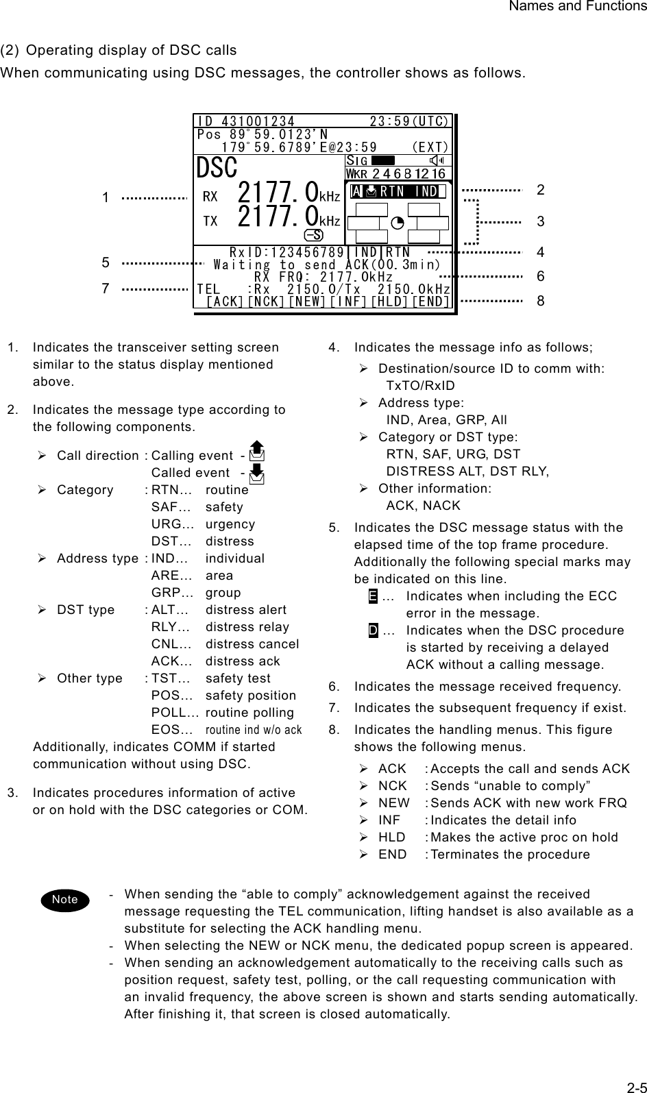
![Names and Functions 2-9 2.4 Display of data terminal The content displayed on the LCD screen in the data terminal is different according to the situation. This section describes a regular screen, the telex communication screen, and the message file edit screen. 2.4.1 Regular screen 1. Indicates the Tx and Rx frequencies. 2. Indicates the communication mode. 3. Indicates the main menu. When pressing the Enter key, indicates the drop-down menu of the main menu pointed by the cursor. ※Telex mode only. 4. Indicates the conditions of the telex communication. ※Telex mode only. 5. Indicates the scanning information in telex mode. When restarting scanning after sending a DSC Auto-ACK or powering off/on, indicates “Running now” instead of the detail information. ※Telex mode only. 6. Indicates the operation result such as the self-diagnosis. 7. Indicates the guide according to the cursor position. Moreover, the locating faults are displayed if any errors occur. z Information: MEM :Internal memory z Information: KBD :Keyboard controlz Information: PRN :Printer z Information: USB :USB Memory 8. Indicates that the connected USB memory is available. Additionally, “ACS” is shown if some time is needed to mount the USB memory. 9. Indicates the antenna tuning condition. z READY :Tuned z NOT READY :Not tuned 10. Indicates the power reduction setting. 2 1 83 4 5 6 97 10 [TLX] Tx= 2174.5kHz/Rx= 2174.5kHz USB File Tune Connect Service System Help STATUS INFO ST-BY[No scanning] TUNER :[READY] Tx.POWER :[HIGH]Move the cursor to the item you want with ↑, ↓, →, ← then press Enter.File manager. Information:MEM KBD PRN USB (Press the <Alt>+I if you want to know detail.)FileFree sig. ST-BY Calling Receive Rephasing Repeat TrafScanning info Tuner/Tx.POWER Last status message](https://usermanual.wiki/Japan-Radio/JSS-2250/User-Guide-2169640-Page-49.png)
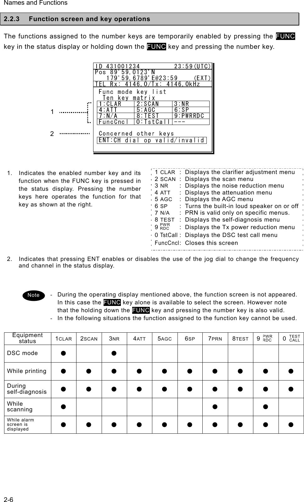
![Names and Functions 2-10 2.4.2 Telex communication screen 1. Indicates the operating condition of the telex communication from the left of each segment as follows. 1) In the autotelex mode, when the free channel signal of the coast station is detected, indicates the “Free Sig”. 2) Indicates the communication mode (ARQ/CFEC/SFEC). ※Indicates “ST-BY” in the standby condition. 3) Indicates “Calling” at the master station, and “Called” at the slave station. 4) Indicates “Send” at the information sending station, and “Receive” at the information receiving station. 5) Indicates "Phasing" while calling and connecting the communication channel and “Rephasing” while reconnecting the channel after the channel is disconnected due to the channel condition in ARQ mode. 6) Indicates “Repeat” in ARQ mode if requested to send the each block or the control signal again. 7) Indicates “Traf” while sending or receiving information and “RQ” while sending or receiving RQ signal. 2. Indicates the telex message or the name of the executed function key. 3. Indicates the usable function keys guide. Each meaning is as follows. z F2 WRU : Requests the answer- back code to the corresponding station. z F3 Hereis : Sends the answerback code of own station. z F4 TMS : Sends the date and the time information. z F5 Over : Exchange the sending and the receiving condition. z F6 POLL : Acquires the sending right if the correspond- ing station (sending) tries to finish the communication in ARQ mode. ※It is available only when the corresponding station is using the modem made of our company. z F8 F.Send : Sends a message file. z F10 Stop : Finishes the telex communication. 1 2 3 [TLX] Tx= 2174.5kHz/Rx= 2174.5kHz USB TELEX Terminal Window ARQMessage start...F2 WRU | F3 Hereis | F4 TMS | F5 Over | F8 F.Send | F10 StopFree sig. ARQ Calling Send Rephasing Repeat Traf](https://usermanual.wiki/Japan-Radio/JSS-2250/User-Guide-2169640-Page-50.png)
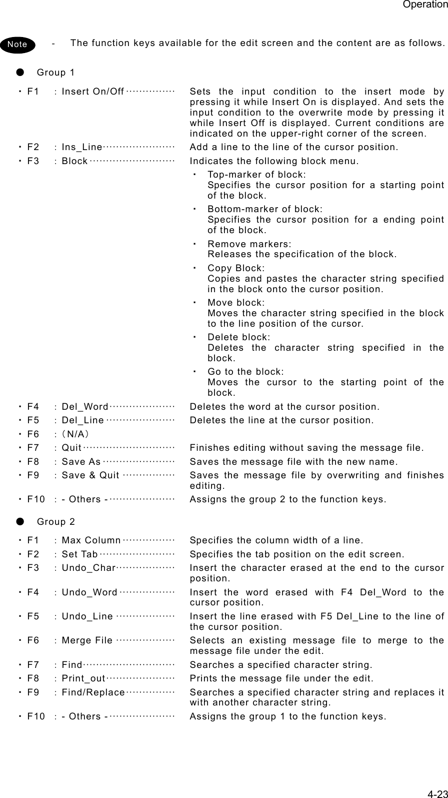
![Names and Functions 2-11 2.4.3 Message file edit screen 1. Indicates the state of the edit screen as follows. z Editing telex file :File name z Line :Line position of cursorz Column :Row position of cursorz Size :Capacity of file z Insert On/Overwrite :Input mode (insert/overwrite) 2. The message file is edited here. 3. The list of the function key is displayed by the following content separately for two groups. z Group 1 ・ F1 :Insert On/Off ・ F2 :Ins_Line ・ F3 :Block ・ F4 :Del_Word ・ F5 :Del_Line ・ F6 : ・ F7 :Quit ・ F8 :Save As ・ F9 :Save & Quit ・ F10 :- Others - z Group 2 ・ F1 :Max Column ・ F2 :Set Tab ・ F3 :Undo_Char ・ F4 :Undo_Word ・ F5 :Undo_Line ・ F6 :Merge File ・ F7 :Find ・ F8 :Print out ・ F9 :Find/Replace ・ F10 :- Others - 1 2 3 [TLX] Tx= 2174.5kHz/Rx= 2174.5kHz USB Editing telex file:001.TLX Line: 1 Column: 1 Size: 0 Insert On[End of File]F1:Insert Off F2:Ins_Line F3:Block F4:Del_Word F5:Del_Line F7:Quit F8:Save As F9:Save & Quit F10: - Others -MFHF](https://usermanual.wiki/Japan-Radio/JSS-2250/User-Guide-2169640-Page-51.png)
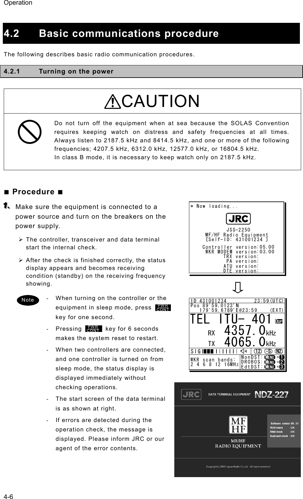
![Operation 4-7 4.2.2 Turning off the power/ Putting into sleep mode CAUTION When completely turning off the power to the equipment, turn off the breakers on the power supply. ■ Procedure ■ Press the key and DIM key simultaneously. After that, the power-off process is activated according to the controllers' status. z When using only one controller Select the desired item below on the popup screen shown at right ⋅ [OK]: Turns off the power. (Puts into sleep (energy saving) mode.) ⋅ [Cancel]: Returns to the previous screen. z When using two controllers On a controller with access rights, select the desired item below on the popup screen shown at right ⋅ [EQP]: Turns off the power. (Puts into sleep (energy saving) mode.) ⋅ [CTRL]: Puts the controller into sleep mode and gives access rights to another controller. ⋅ [Cancel]: Returns to the previous screen. On a controller without access rights, select the desired item below on the displayed popup screen at right ⋅ [OK]: Puts one controller into sleep mode. ⋅ [Cancel]: Returns to the previous screen. ¾ In sleep mode, the equipment changes to the following statuses. ⋅ If all the equipment goes to sleep, the ALM lamp lights green to indicate the DSC watch keeping receiver is on and operating. ⋅ The POWER lamp of the data terminal blinks. ⋅ If a distress or urgent DSC message is received, the equipment turns on automatically and sounds an alarm. ¾ Turn off both the AC and DC breakers if turning off the power at the NBD-2250/2500 Power supply. Note TEL ITU- 401 4357.0 4065.0RX kHzTX kHzNonDST: +DROBOS: +EdtDST: +ID 431001234 23:59(UTC)Pos 89゚59.0123'N 179゚59.6789'E@23:59 (EXT)SIGWKR scan bands:2 4 6 8 12 16MHz OK to sleep the MF/HF equipment? [ OK ] [Cancel][ OK ]PWRCONTTEL ITU- 401 4357.0 4065.0RX kHzTX kHzNonDST: +DROBOS: +EdtDST: +ID 431001234 23:59(UTC)Pos 89゚59.0123'N 179゚59.6789'E@23:59 (EXT)SIGWKR scan bands:2 4 6 8 12 16MHz OK to sleep the MF/HF equipment, or only this controller? [EQP] [CTRL] [Cancel][EQP]TEL ITU- 401 4357.0 4065.0RX kHzTX kHzNonDST: +DROBOS: +EdtDST: +ID 431001234 23:59(UTC)Pos 89゚59.0123'N 179゚59.6789'E@23:59 (EXT)SIGWKR scan bands:2 4 6 8 12 16MHz OK to sleep this controller? [ OK ] [Cancel][ OK ]](https://usermanual.wiki/Japan-Radio/JSS-2250/User-Guide-2169640-Page-59.png)
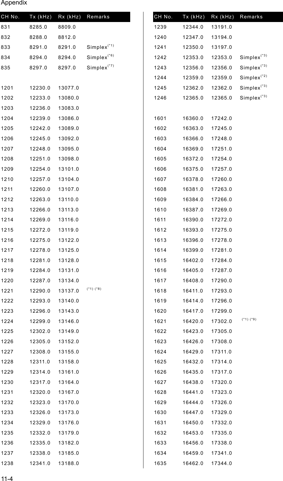
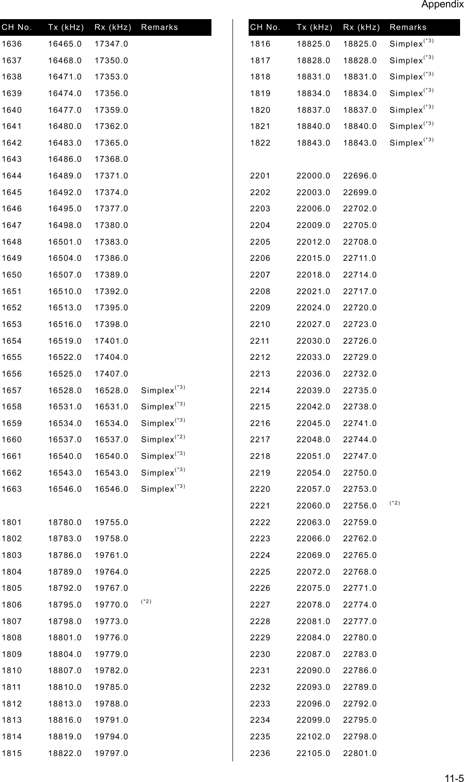
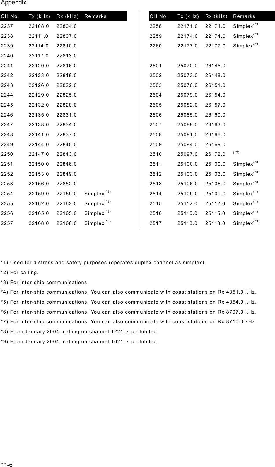
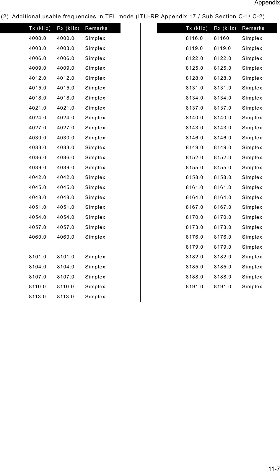
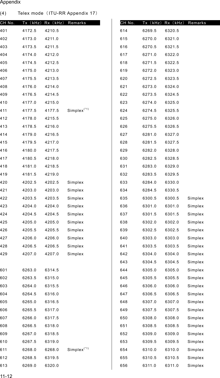
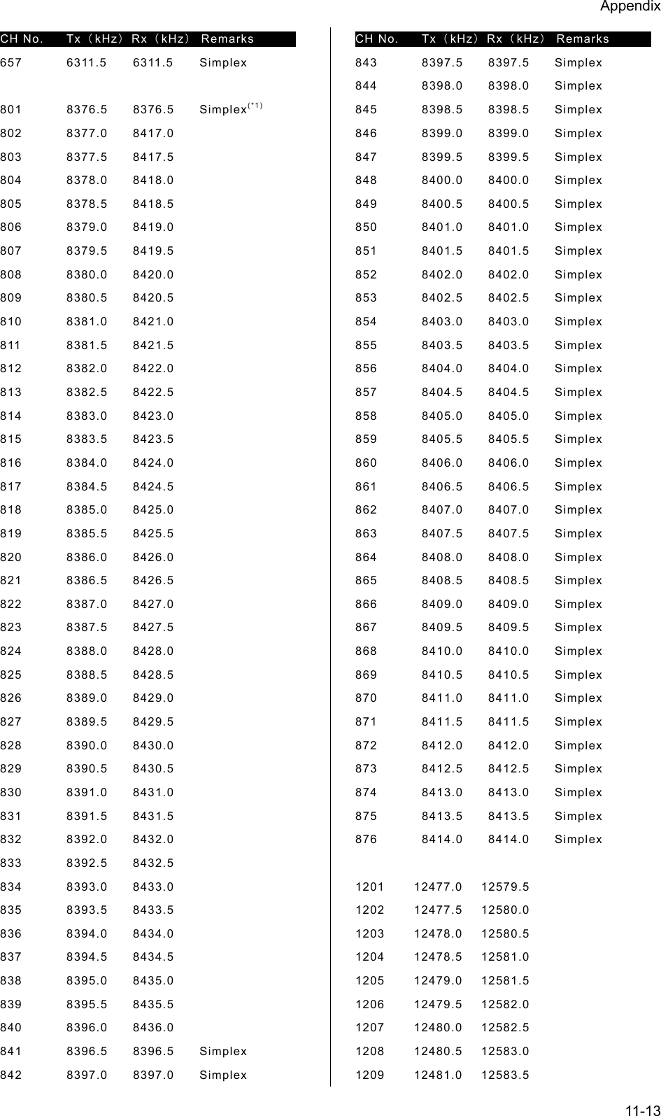
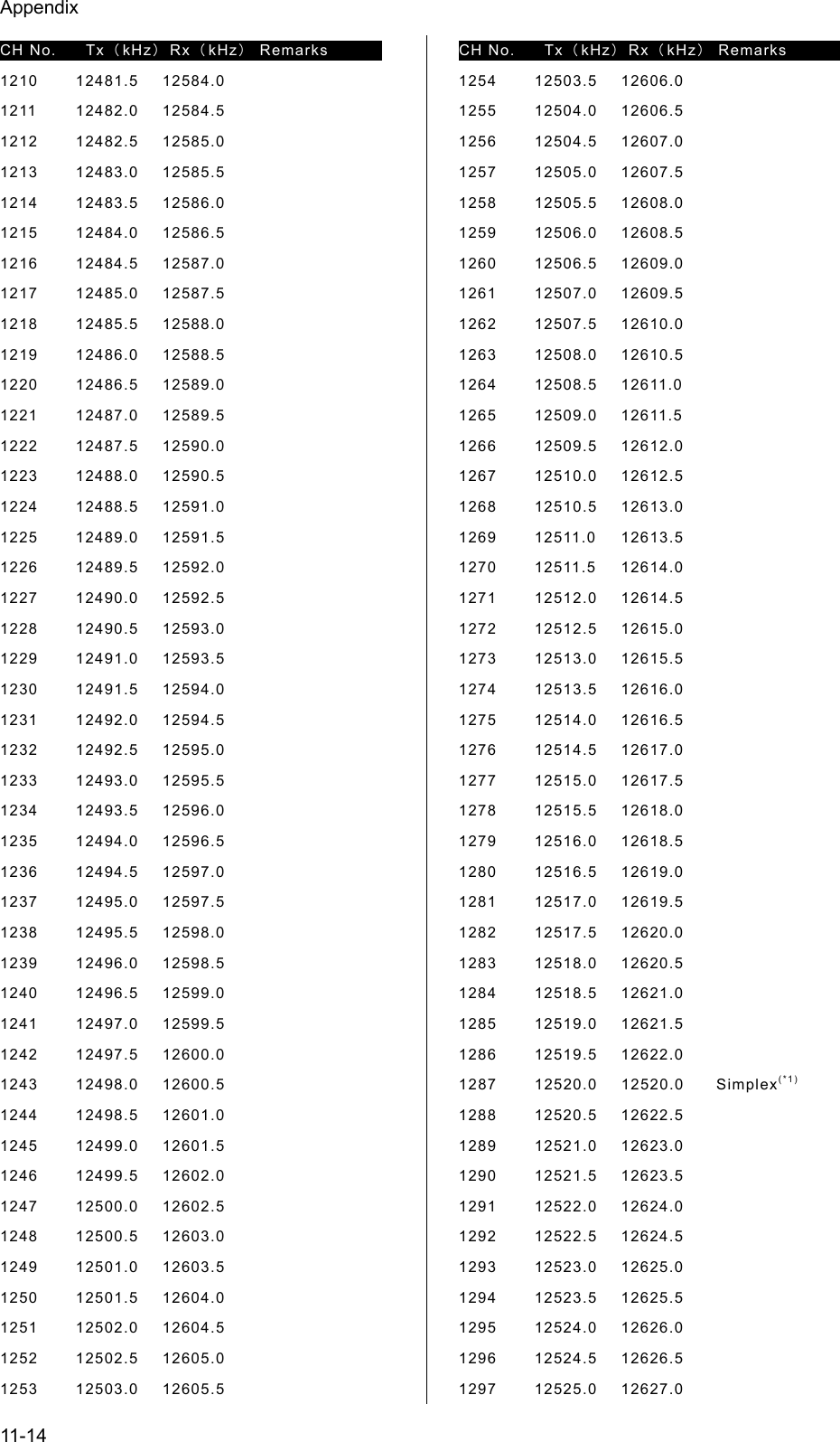
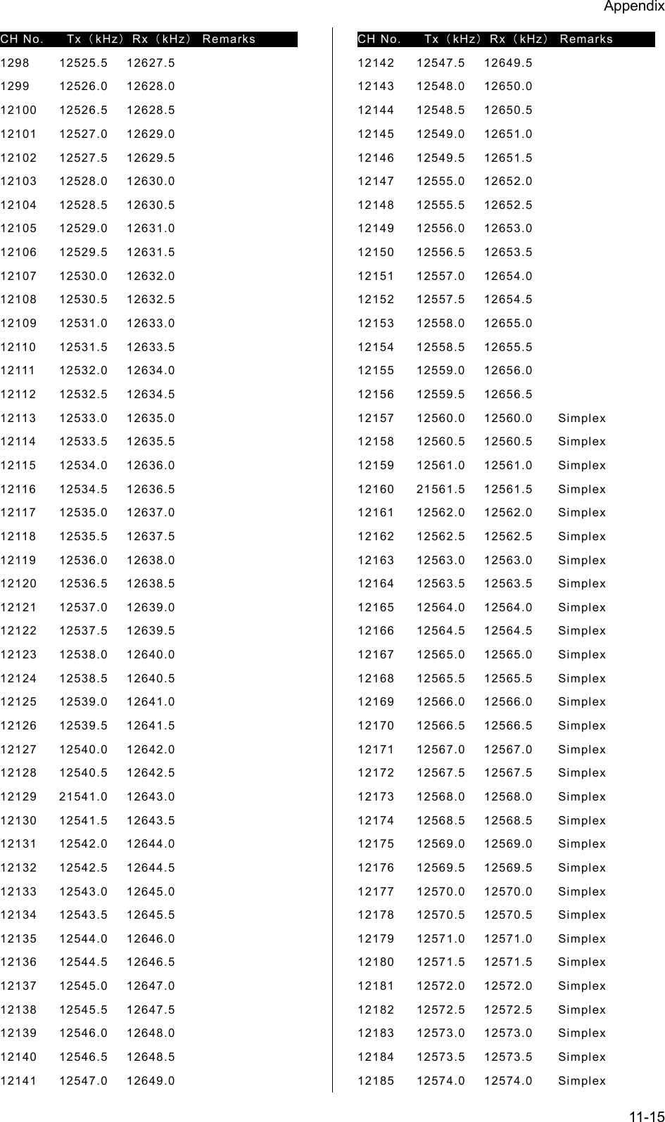
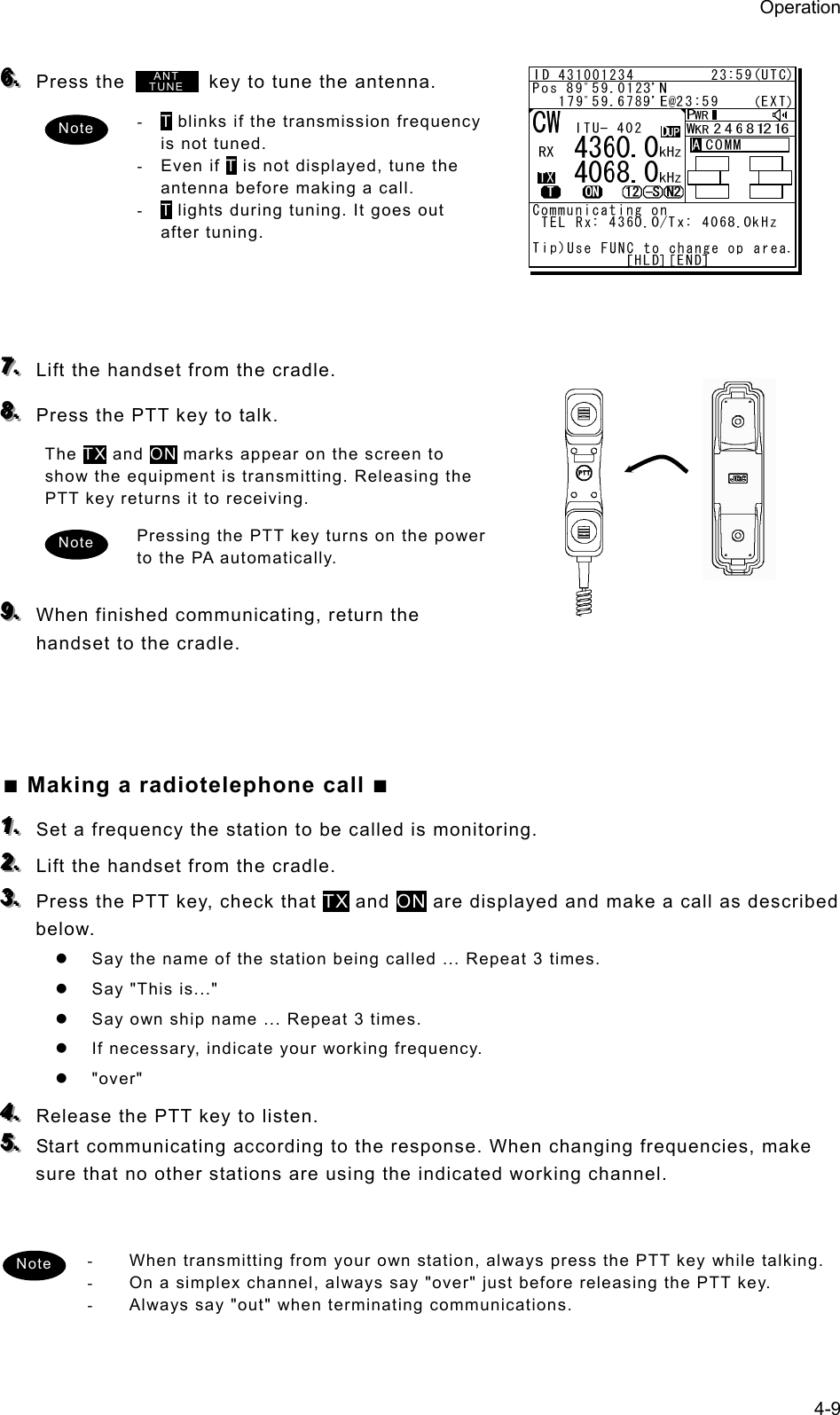
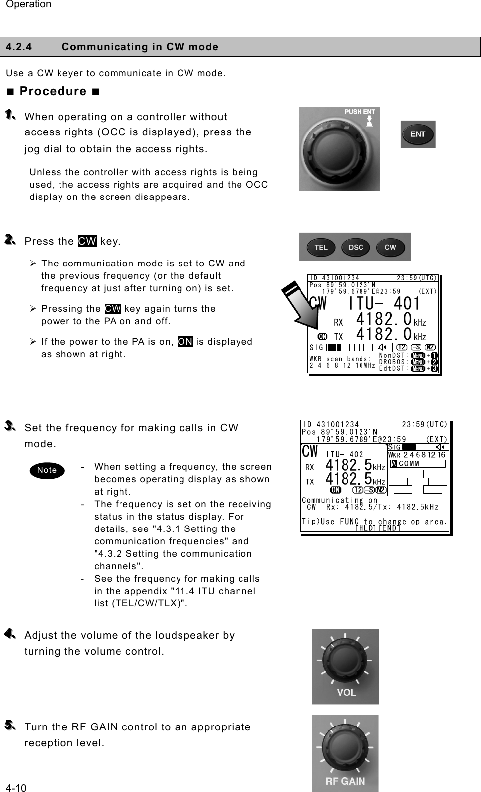
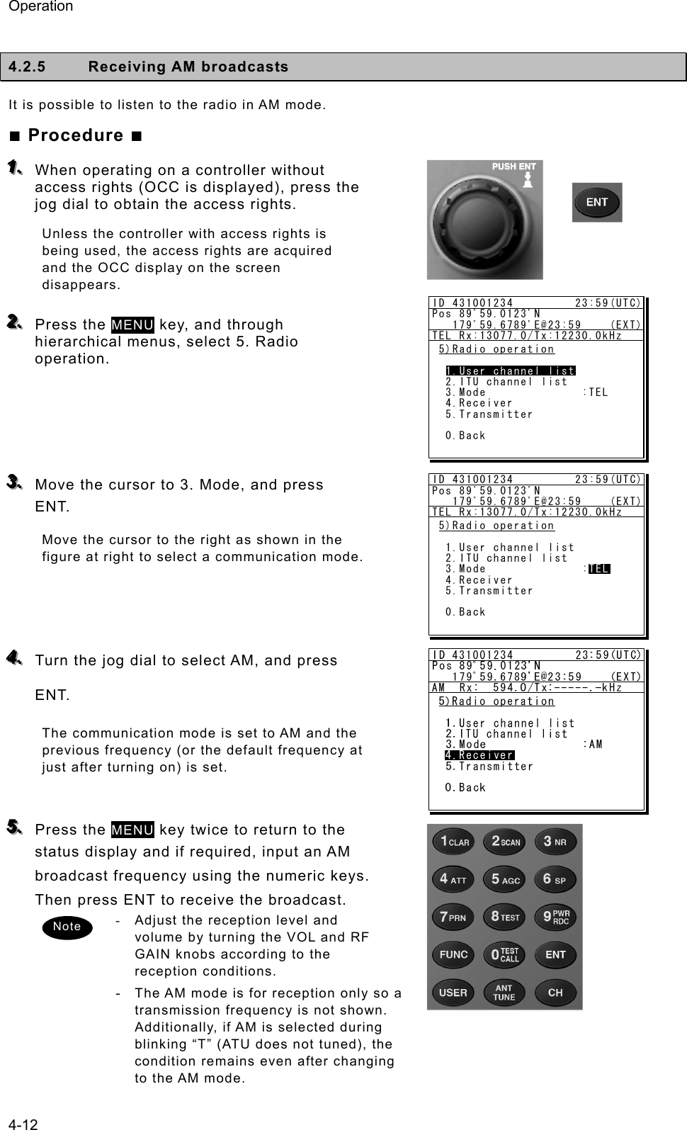
![Operation 4-8 4.2.3 Communicating in radiotelephone mode Use the handset to communicate in radiotelephone mode. ■ Procedure ■ 111... When operating on a controller without access rights (OCC is displayed), press the jog dial to obtain the access rights. Unless the controller with access rights is being used, the access rights are acquired and the OCC display on the screen disappears. 222... Press the TEL key. ¾ The communication mode is set to TEL and the previous frequency (or the default frequency at just after turning on) is set. ¾ Pressing the TEL key again turns the power to the PA on and off. ¾ If the power to the PA is on, ON is displayed as shown at right. 333... Set the frequency for making calls in radiotelephone mode. - When setting a frequency, the screen becomes operating display as shown at right. - The frequency is set on the receiving status in the status display or the operating display. For details, see "4.3.1 Setting the communication frequencies" and "4.3.2 Setting the communication channels". - See the frequency for making calls in the appendix "11.4 ITU channel list (TEL/CW/TLX)". 444... Adjust the volume of the loudspeaker by turning the volume control. 555... Turn the RF GAIN control to an appropriate reception level. TEL ITU- 401 4357.0 4065.0RX kHzTX kHzNonDST: +DROBOS: +EdtDST: +ID 431001234 23:59(UTC)Pos 89゚59.0123'N 179゚59.6789'E@23:59 (EXT)SIGWKR scan bands:2 4 6 8 12 16MHzNote ID 431001234 23:59(UTC)Pos 89゚59.0123'N 179゚59.6789'E@23:59 (EXT)Communicating on TEL Rx: 4360.0/Tx: 4068.0kHzTip)Use FUNC to change op area. [HLD][END]AATEL 4360.0 4068.0ITU- 402](https://usermanual.wiki/Japan-Radio/JSS-2250/User-Guide-2169640-Page-60.png)
![Operation 4-13 4.2.6 Communicating in telex mode (TLX) When communicating in the telex mode, the data terminal is used. In the telex communication, the ARQ (Automatic Repeat reQuest) mode and FEC (Forward Error Correction) mode are available to communicate between two stations and to broadcast respectively. Additionally in the FEC mode, there are two modes of the CFEC (Collective Forward Error Correction) mode for unspecified receivers and SFEC (Selective Forward Error Correction) mode for specified receivers, which are selectable according to the purpose. After starting the telex communication, always use the data terminal until to stop it even though the controller can terminate that communication with END option forcibly. 44..22..66..11 ARQ mode operation To start the ARQ communication, make a call of the station by inputting the SELCAL number (4 digits for the coast station, 5 digits for the ship station or 9 digits) and the work frequency. After initiating the call, when receiving the response from the called station and the communication channel is established, the ARQ communication will be available. ■ Procedure ■ 111... If displaying the message of "Press Enter key to get the access right in the NBDP mode…" on the data terminal, press Enter key on the keyboard. The operation of the data terminal becomes possible in the telex mode, except when the controller is used. 222... On the main menu and the dropdown menu, select Connect Î ARQ with Enter key. ¾ The registered station list is displayed. ¾ When selecting [Manual] on this station list, the ID and frequency or ITU channel can be input manually. Attention](https://usermanual.wiki/Japan-Radio/JSS-2250/User-Guide-2169640-Page-65.png)
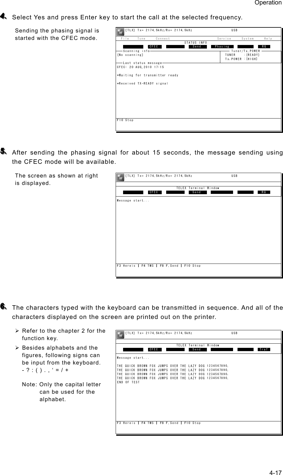
![Operation 4-14 333... Select the station to be called with the cursor, and press Enter key. ¾ The frequency list of the selected radio station is displayed. ¾ If the position of the station is registered, the MUF (maximum usable frequency) is displayed in the lowest line as a reference to select the frequency. Also, the MUF can be calculated by the menu of Service Î MUF calculation. 444... Select the work frequency with the cursor, and press Enter key. ¾ The selected frequency is set and the antenna is tuned to the frequency. ¾ The message as shown at right is displayed to confirm that the channel is busy. 555... Select Yes and press Enter key to start the call at the selected frequency. Calling of the station is started with the ARQ mode. 666... When receiving the periodic reply from the called station and the communication channel is established, th e ARQ communication will be available. ¾ The screen as shown at right is displayed. ¾ If receiving no response within one minute, the calling will be ceased automatically. In this case, the same call is inhibited for about one minute. Frequency list Name : [Station 01 ] ID : [004310123] Loc : [N33゚45' E138゚12'] No. Tx.F Rx.F No. Tx.F Rx.F 1 4202.5 4202.5 11 22354.5 22354.5 [Set] 2 4205.0 4205.0 12 25193.0 25193.0 [Print] 3 6300.5 6300.5 13 25208.0 25208.0 [Cancel] 4 6303.0 6303.5 14 5 8396.5 8396.5 15 6 8399.0 8399.0 16 7 12560.0 12560.0 17 8 16785.0 16785.0 18 9 18893.0 18893.0 19 10 22352.0 22352.0 20 MUF: 9MHz, Range: 2537Miles, Sunspot: 14 1 4202.5 4202.5 [TLX] Tx= 2174.5kHz/Rx= 2174.5kHz USB File Tune Connect Service System Help STATUS INFO ST-BY[No scanning] TUNER :[READY] Tx.POWER :[HIGH]ARQ: 20 AUG,2010 17:15 Station:[Station 01] ID:[004310123] Loc:[N33゚45'E138゚12']*Waiting for transmitter ready*Received TX-READY signalF10 StopFree sig. ARQ Calling Send Phasing Repeat TrafScanning info Tuner/Tx.POWER Last status message [TLX] Tx= 2174.5kHz/Rx= 2174.5kHz USB Station ID:[004310123] TELEX Terminal Window ARQMessage start...F2 WRU | F3 Hereis | F4 TMS | F5 Over | F8 F.Send | F10 StopFree sig. ARQ Calling Send Rephasing Repeat Traf](https://usermanual.wiki/Japan-Radio/JSS-2250/User-Guide-2169640-Page-66.png)
![Operation 4-15 777... The characters typed with the keyboard can be transmitted in sequence. And all of the characters displayed on the screen are printed out on the printer. ¾ In the ARQ mode, it is possible to alternate the information sending station (ISS) and the information receiving station (IRS). ¾ While “Send” is displayed on the segment that shows the operation status, the own station is ISS and able to send a message. ¾ After sending a message, send “+?” to give the sending right to the IRS. ¾ While the condition is IRS, the sending right can be acquired by pressing F5 Over without waiting for “+?” from ISS. Further, refer to the chapter 2 for other function keys. ¾ Besides alphabets and the figures, following signs can be input from the keyboard. - ? : ( ) . , ‘ = / + Note: As the alphabets, capital letters only are available. 888... To finish the communication, press F10 Stop key. ¾ When receiving the reply to the request for the end of communication, returns to the standby condition. ¾ F10 Stop is always available while communicating regardless of ISS/ IRS. Note that if pressing the F10 key during IRS condition, the station becomes ISS temporally to send the end of communication. ¾ When pressing the F10 Stop key during sending a message, the sending message buffer is cleared at once and initiates the end of communication process. ¾ When POLL is set at IRS and the end of communication is requested by ISS, the IRS can acquire the sending right without ending the communication. When receiving the ARQ call from another station during standby condition, the operation under the communication is basically similar. Note [TLX] Tx= 2174.5kHz/Rx= 2174.5kHz USB Station ID:[004310123] TELEX Terminal Window ARQMessage start...THE QUICK BROWN FOX JUMPS OVER THE LAZY DOG 1234567890.THE QUICK BROWN FOX JUMPS OVER THE LAZY DOG 1234567890.THE QUICK BROWN FOX JUMPS OVER THE LAZY DOG 1234567890.THE QUICK BROWN FOX JUMPS OVER THE LAZY DOG 1234567890.END OF TESTF2 WRU | F3 Hereis | F4 TMS | F5 Over | F8 F.Send | F10 StopFree sig. ARQ Calling Send Rephasing Repeat Traf](https://usermanual.wiki/Japan-Radio/JSS-2250/User-Guide-2169640-Page-67.png)
![Operation 4-16 44..22..66..22 CFEC mode operation (1) Sending with CFEC Messages can be sent as a broadcast on the selected work frequency using the CFEC mode. ■ Procedure ■ 111... If displaying the message of "Press Enter key to get the access right in the NBDP mode…" on the data terminal, press Enter key on the keyboard. The operation of the data terminal becomes possible in the telex mode, except when the controller is used. 222... On the main menu and the dropdown menu, select Connect Î CFEC with Enter key. ¾ Input the frequency or ITU channel on the screen as shown at right. ¾ To input the frequency, press Enter key to move the cursor to the right. ¾ To input the ITU channel, select the ITU channel button and press Enter key to display the specific screen as shown at right. Then press Enter key to move the cursor to the right. 333... Input the work frequency or ITU channel, and press Enter key. ¾ The selected frequency is set and the antenna is tuned to the frequency. ¾ The message as shown at right is displayed to confirm that the channel is busy. [TEL] Tx= 2174.5kHz/Rx= 2174.5kHz USB File Tune Connect Service System Help STATUS INFO[No scanning] TUNER :[READY] Tx.POWER :[HIGH]Press Enter key to get the access right in the NBDP mode...Scanning info Tuner/Tx.POWER Last status message](https://usermanual.wiki/Japan-Radio/JSS-2250/User-Guide-2169640-Page-68.png)
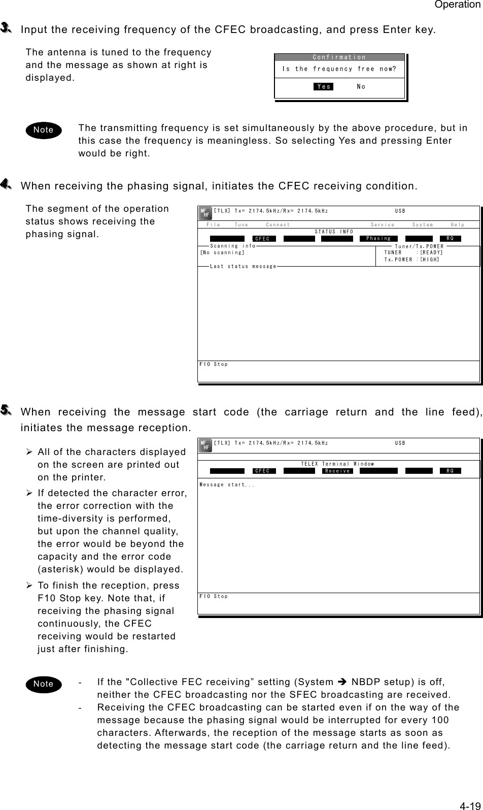
![Operation 4-18 777... To finish the communication, press F10 Stop key. ¾ After sending the end of communication for about five seconds, returns to the standby condition. ¾ When pressing the F10 Stop key during sending a message, the sending message buffer is cleared at once and initiates the end of communication process. (2) Receiving CFEC broadcasting CFEC broadcasting messages can be received on the selected work frequency. ■ Procedure ■ 111... If displaying the message of "Press Enter key to get the access right in the NBDP mode…" on the data terminal, press Enter key on the keyboard. The operation of the data terminal becomes possible in the telex mode, except when the controller is used. 222... On the main menu and the dropdown menu, select Tune Î Tx/Rx frequency set with Enter key. ¾ The screen as shown at right is displayed. ¾ To input the frequency, press Enter key to move the cursor to the right. ¾ To select the frequency from the frequency list, select Tune Î Frequency list and open the frequency list of either one of radio stations. [TEL] Tx= 2174.5kHz/Rx= 2174.5kHz USB File Tune Connect Service System Help STATUS INFO[No scanning] TUNER :[READY] Tx.POWER :[HIGH]Press Enter key to get the access right in the NBDP mode...Scanning info Tuner/Tx.POWER Last status message [TLX] Tx= 2174.5kHz/Rx= 2174.5kHz USB File Tune Connect Service System Help STATUS INFO ST-BY[No scanning] TUNER :[READY] Tx.POWER :[HIGH]CFEC: 20 AUG,2010 17:15*Waiting for transmitter ready*Received TX-READY signalMove the cursor to the item you want with ↑, ↓, →, ← then press Enter.File manager.FileFree sig. ST-BY Calling Receive Rephasing Repeat TrafScanning info Tuner/Tx.POWER Last status message](https://usermanual.wiki/Japan-Radio/JSS-2250/User-Guide-2169640-Page-70.png)
![Operation 4-20 44..22..66..33 SFEC mode operation Messages can be sent to the specific stations as a broadcast on the selected work frequency using the SFEC mode. Additionally, regarding the SFEC reception, refer to the previous section because it is similar to the CFEC reception. ■ Procedure ■ 111... If displaying the message of "Press Enter key to get the access right in the NBDP mode…" on the data terminal, press Enter key on the keyboard. The operation of the data terminal becomes possible in the telex mode, except when the controller is used. 222... On the main menu and the dropdown menu, select Connect Î SFEC with Enter key. ¾ The registered station list is displayed. ¾ When selecting [Manual] on this station list, the ID and frequency or ITU channel can be input manually. 333... Select the station to be called with the cursor, and press Enter key. ¾ The frequency list of the selected radio station is displayed. ¾ If the position of the station is registered, the MUF (maximum usable frequency) is displayed in the lowest line as a reference to select the frequency. Also, the MUF can be calculated by the menu of Service Î MUF calculation. Station selection No. Station Name ID Location F.Sig 1 Station 01 004310123 N33゚45' E138゚12' DOTDOT [Select] 2 Station 02 004311234 N37゚22' E135゚51' DOTDOT [Manual] 3 Station 03 431012345 [Cancel] 4 5 6 7 8 9 10 ↓ 1 Station 01 004310123 N33゚45' E138゚12' DOTDOT [TEL] Tx= 2174.5kHz/Rx= 2174.5kHz USB File Tune Connect Service System Help STATUS INFO[No scanning] TUNER :[READY] Tx.POWER :[HIGH]Press Enter key to get the access right in the NBDP mode...Scanning info Tuner/Tx.POWER Last status message](https://usermanual.wiki/Japan-Radio/JSS-2250/User-Guide-2169640-Page-72.png)
![Operation 4-21 444... Select the work frequency with the cursor, and press Enter key. ¾ The selected frequency is set and the antenna is tuned to the frequency. ¾ The message as shown at right is displayed to confirm that the channel is busy. 555... Select Yes and press Enter key to start the call at the selected frequency. ¾ The SFEC broadcasting is started. ¾ First, the phasing signal same with CFEC mode is sent. 666... After sending the phasing signal followed by the SELCAL number, the message sending using the SFEC mode will be available. The screen as shown at right is displayed. The following procedure is the same as the CFEC mode. Note [TLX] Tx= 2174.5kHz/Rx= 2174.5kHz USB Station ID:[004310123] TELEX Terminal Window ARQMessage start...F3 Hereis | F4 TMS | F8 F.Send | F10 StopFree sig. SFEC Calling Send Rephasing Repeat RQ](https://usermanual.wiki/Japan-Radio/JSS-2250/User-Guide-2169640-Page-73.png)
![Operation 4-22 44..22..66..44 Editing telex messages When communicating in the telex mode, the message file can be sent, which is prepared beforehand as follows. ■ Procedure ■ 111... If displaying the message of "Press Enter key to get the access right in the NBDP mode…" on the data terminal, press Enter key on the keyboard. The operation of the data terminal becomes possible in the telex mode, except when the controller is used. 222... On the main menu and the dropdown menu, select File Î Edit new file with Enter key. ¾ The editing screen is displayed as shown at right. ¾ To edit an existing file, select File Î Edit existing file. 333... Make the message with the keyboard. ¾ Besides alphabets and the figures, following signs can be input from the keyboard. - ? : ( ) . , ‘ = / + ¾ Only the capital letter can be used for the alphabet. ¾ When the number of characters for each line becomes more than 70 or a specified number, line feed is automatically inserted. ¾ When pressing the Tab key, inserts the space of the number set by F2 Set tab is inserted. 444... Press F9 (Save & Quit) key when saving the message the file and finishing editing. After closing the editing screen, returns to the regular screen. [TEL] Tx= 2174.5kHz/Rx= 2174.5kHz USB File Tune Connect Service System Help STATUS INFO[No scanning] TUNER :[READY] Tx.POWER :[HIGH]Press Enter key to get the access right in the NBDP mode...Scanning info Tuner/Tx.POWER Last status message [TLX] Tx= 2174.5kHz/Rx= 2174.5kHz USB Editing telex file:001.TLX Line: 1 Column: 1 Size: 0 Insert On[End of File]F1:Insert Off F2:Ins_Line F3:Block F4:Del_Word F5:Del_Line F7:Quit F8:Save As F9:Save & Quit F10: - Others -](https://usermanual.wiki/Japan-Radio/JSS-2250/User-Guide-2169640-Page-74.png)
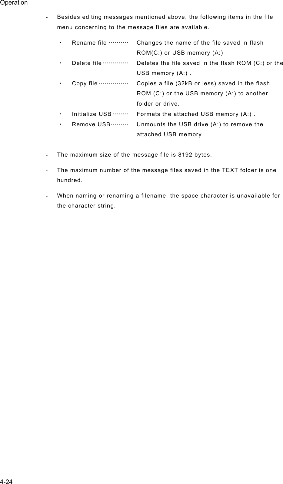
![Operation 4-25 4.3 Setting the radio This section describes how to set the communication frequencies and how to use the receiver and transceiver functions. 4.3.1 Setting the communication frequencies Use the free frequency input mode to input the communication frequencies directly. ■ Procedure ■ 111... In the status display, use the numeric keypad to input the frequency. - When 1 is input using the numeric keypad, it appears on the far right as shown in the screen on the right. - In the user/ITU channel input mode, press the CH key once or twice to hide the channel display. 222... Input numbers to the 0.1 kHz place and press ENT. The transmission frequency input mode opens as shown in the screen at right. For a simplex frequency, press ENT to automatically input the same frequency as the receiving frequency to complete communication frequency settings. 333... Input the transmission frequency in the same way as the reception frequency. 444... Input numbers to the 0.1 kHz place and press ENT. The communication frequency settings are complete and the screen shows the operating display. - Turning the jog dial on the status display changes the reception frequency on the 0.1 kHz scale. For simplex frequencies, the transmission frequency is changed at the same time. - The above operation is also available on the transceiver setting screen of the operating display. - The above operation is unavailable in the telex mode. The telex frequency is set with the menu of the data terminal, as Tune Î Tx/Rx frequency set. Note Note Note TEL -----.1 2331.5RX kHzTX kHzNonDST: +DROBOS: +EdtDST: +ID 431001234 23:59(UTC)Pos 89゚59.0123'N 179゚59.6789'E@23:59 (EXT)SIGWKR scan bands:2 4 6 8 12 16MHzTEL 12345.0-----.-RX kHzTX kHzNonDST: +DROBOS: +EdtDST: +ID 431001234 23:59(UTC)Pos 89゚59.0123'N 179゚59.6789'E@23:59 (EXT)SIGWKR scan bands:2 4 6 8 12 16MHzTEL 12345.0---12.3RX kHzTX kHzNonDST: +DROBOS: +EdtDST: +ID 431001234 23:59(UTC)Pos 89゚59.0123'N 179゚59.6789'E@23:59 (EXT)SIGWKR scan bands:2 4 6 8 12 16MHzID 431001234 23:59(UTC)Pos 89゚59.0123'N 179゚59.6789'E@23:59 (EXT)Communicating on TEL Rx:12345.0/Tx:12345.0kHzTip)Use FUNC to change op area. [HLD][END]AATEL 12345.0 12345.0](https://usermanual.wiki/Japan-Radio/JSS-2250/User-Guide-2169640-Page-77.png)
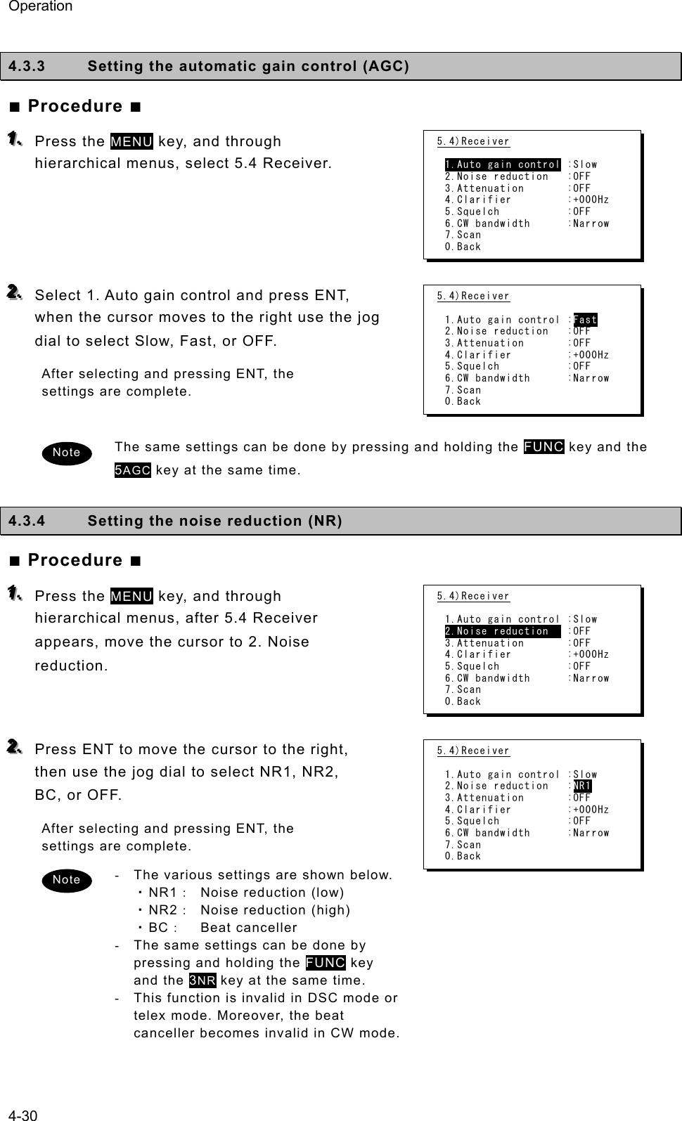
![Operation 4-26 4.3.2 Setting the communication channels Besides the free frequencies described previously, ITU channel mode and user channel modes can also be set. The ITU channel mode is mode for using channels based on the international standard and is built-in to the equipment. The user channel mode is the mode for using channels on pre-registered frequencies. These modes can be used according to the operations. (1) Selecting a frequency and channel input mode ■ Procedure ■ 111... Set the screen of the status display or the operating display. The operating display at right shows free frequency mode. 222... Press the CH key. As shown below, each time the CH key is pressed the mode changes in order from the free frequency mode, ITU channel mode, to the user channel mode. (Free frequency input mode) (ITU channel mode) (User channel mode) - If changed to the ITU channel mode, the communication mode of the free frequency input mode and the previous (or lowest) ITU channel number are applied. - The above operation is unavailable in the telex mode. - If the communication mode is changed by pressing the TEL, DSC, or CW keys, the free frequency input mode is set. Note CHCH CHID 431001234 23:59(UTC)Pos 89゚59.0123'N 179゚59.6789'E@23:59 (EXT)Communicating on TEL Rx: 4360.0/Tx: 4068.0kHzTip)Use FUNC to change op area. [HLD][END]AATEL 4360.0 4068.0ITU- 402ID 431001234 23:59(UTC)Pos 89゚59.0123'N 179゚59.6789'E@23:59 (EXT)Communicating on TEL Rx: 4357.0/Tx: 4065.0kHzTip)Use FUNC to change op area. [HLD][END]AATEL 4357.0 4065.0U01- 001](https://usermanual.wiki/Japan-Radio/JSS-2250/User-Guide-2169640-Page-78.png)
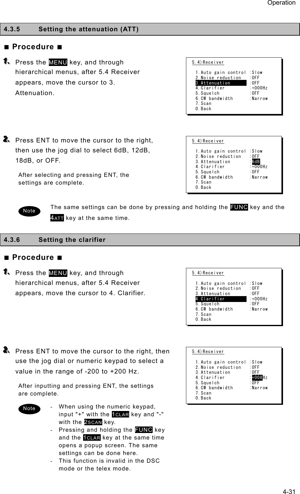
![Operation 4-27 (2) Setting the ITU channels ■ Procedure ■ 111... After setting the TEL, DSC or CW modes, press the CH key to set the display to the ITU channel mode. 222... Input the channel by using the numeric keypad. When 4 is input using the numeric keypad, it appears on the far right as shown in the screen on the right. 333... Input the rest of the digits and press ENT. The input ITU channel frequency is displayed and the settings are complete. - See the appendix "11.4 ITU channel list (TEL/CW/TLX)" for a list of pre-installed ITU channels and their frequencies. - Besides doing settings with the numeric keypad, settings can also be done with the jog dial. - For DSC mode, normally perform the above procedure to receive the routine message. Furthermore, when sending a DSC message, the calling frequency is set via the menu automatically and the above procedure is not needed. - The above operation is unavailable in the telex mode. The ITU channel in the telex mode is set with the controller menu 5.2 ITU channel list, or the data terminal menu operation, as Tune Î ITU channel set. Note Note ID 431001234 23:59(UTC)Pos 89゚59.0123'N 179゚59.6789'E@23:59 (EXT)Communicating on TEL Rx: 4360.0/Tx: 4068.0kHzTip)Use FUNC to change op area. [HLD][END]AATEL 4360.0 4068.0ITU- 4ID 431001234 23:59(UTC)Pos 89゚59.0123'N 179゚59.6789'E@23:59 (EXT)Communicating on TEL Rx: 4357.0/Tx: 4065.0kHzTip)Use FUNC to change op area. [HLD][END]AATEL 4357.0 4065.0ITU- 401](https://usermanual.wiki/Japan-Radio/JSS-2250/User-Guide-2169640-Page-79.png)
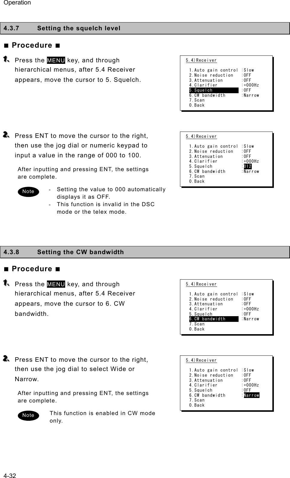
![Operation 4-28 (3) Setting user channels A total of 20 groups with 20 channels set to each group (i.e. 400 channels) can be registered on the equipment. This section explains how to set channels that are already registered. ■ Procedure ■ 111... Use the CH key to set the display to the user channel mode status display. 222... Pressing ENT causes the channel group number to blink so a channel group can be input. Use the numeric keypad or jog dial to input the number of a registered group. When 2 is input using the numeric keypad, it appears on the far right as shown in the screen on the right. 333... After inputting a group number, pressing ENT causes the channel number to blink so a user channel can be input. Use the numeric keypad or jog dial to input the number of a registered channel. When 3 is input using the numeric keypad, it appears on the far right as shown in the screen on the right. 444... Input the rest of the digits and press ENT. ¾ The input user channel frequency is displayed and the settings are complete. ¾ The group name is displayed for 3 seconds after the settings are done. - Channels can be set directly in the status display or the operating display by using the numeric keypad or the jog dial without setting a channel group. After inputting with the numeric keypad, press ENT. - See "5.4 Registering user channels" for how to register frequencies to user channels. - The user channel of the telex mode is set with the menu of the data terminal, as Tune Î Frequency list. Note Note Note ID 431001234 23:59(UTC)Pos 89゚59.0123'N 179゚59.6789'E@23:59 (EXT)Communicating on TEL Rx: 4357.0/Tx: 4065.0kHzTip)Use FUNC to change op area. [HLD][END]AATEL 4357.0 4065.0U20- 3](https://usermanual.wiki/Japan-Radio/JSS-2250/User-Guide-2169640-Page-80.png)
![Operation 4-29 (4) Using channel lists Besides the procedure above, user channels (except the telex mode) and ITU channels can also be set from the channel lists (5.1 User channel list or 5.2 ITU channel list). This section explains how to set channels that are already registered from the user channel list. ■ Procedure ■ 111... Press the MENU key, and through hierarchical menus, select 5. Radio operation. 222... Select 1. User channel list and press ENT. The user channel list index (group list) as shown at right is displayed. 333... Select the intended channel group and press ENT. The user channel list as shown at right is displayed. 444... Select the channel to set and press ENT. The user channel settings are complete, the status display is displayed. 5) Radio operation 1.User channel list 2.ITU channel list 3.Mode :TEL 4.Receiver 5.Transmitter 0.Back 5.1)User channel list (index) No CH group name Type 01 JRC Tokyo TEL 02030405060708Pacific ABC CW 5.1)User channel list (table) Name: JRC Tokyo Type: TEL CHNo Rx[kHz] Tx[kHz] Mode 001 4357.0 4065.0 TEL 002 003 004 005 006 4360.0 4363.0 4366.0 4369.0 4372.0 4068.0 4071.0 4074.0 4077.0 4080.0 TEL TEL TEL TEL TEL](https://usermanual.wiki/Japan-Radio/JSS-2250/User-Guide-2169640-Page-81.png)
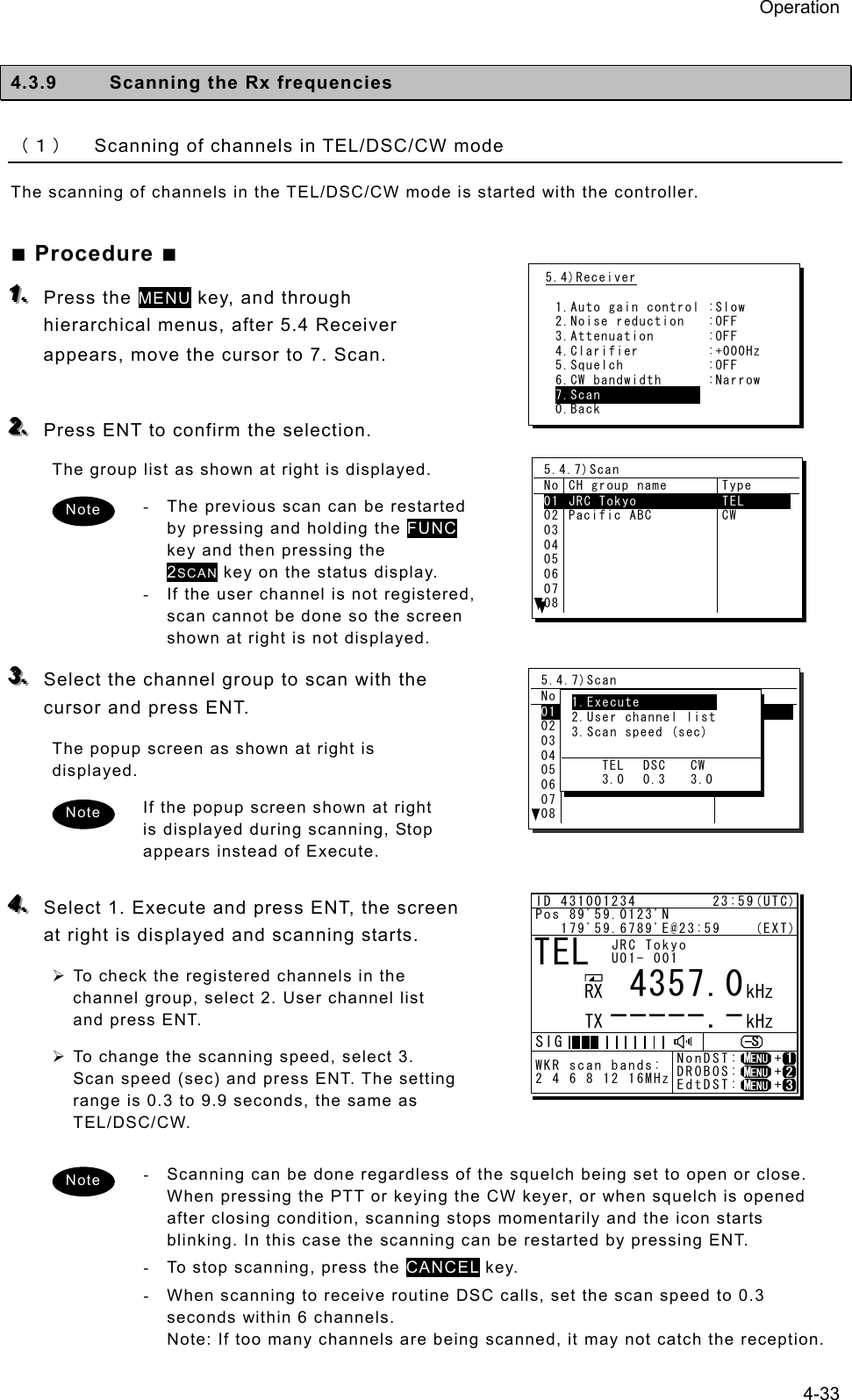
![Operation 4-34 (2) Scanning of channels in telex mode The scanning of channels in the telex mode is started with the data terminal. ■ Procedure ■ 111... If displaying the message of "Press Enter key to get the access right in the NBDP mode…" on the data terminal, press Enter key on the keyboard. The operation of the data terminal becomes possible in the telex mode, except when the controller is used. 222... On the main menu and the dropdown menu, select Tune Î Scanning start with Enter key. The registered station list is displayed. 333... Select the radio station having the channel group to be scanned with the cursor, and press Enter key. The antenna is tuned to the every frequency registered in the selected radio station. The screen at right is displayed while tuning the antenna. 444... After completing the antenna tuning, scanning starts. ¾ The screen as shown at right is displayed while scanning. ¾ When receiving a call by the ARQ or FEC mode, scanning stops and the communication starts. After finishing the communication, scanning restarts automatically. ¾ The scanning speed can be changed with the menu on the regular screen, as System Î Scan speed. ¾ When breaking the scanning, select Tune Î Scanning stop. [TEL] Tx= 2174.5kHz/Rx= 2174.5kHz USB File Tune Connect Service System Help STATUS INFO[No scanning] TUNER :[READY] Tx.POWER :[HIGH]Press Enter key to get the access right in the NBDP mode...Scanning info Tuner/Tx.POWER Last status message [TLX] Tx=-----.-kHz/Rx= 2174.5kHz USB File Tune Connect Service System Help STATUS INFO ST-BYNo. Station:[Station 01 ] ID:[004310123] TUNER :[-----]01 Location:[N33゚45'E138゚12'] F.Sig:[DOTDOT] Tx.POWER :[HIGH]Move the cursor to the item you want with ↑, ↓, →, ← then press Enter.File manager.FileFree sig. ST-BY Calling Receive Rephasing Repeat TrafScanning info Tuner/Tx.POWER Last status message](https://usermanual.wiki/Japan-Radio/JSS-2250/User-Guide-2169640-Page-86.png)
![Operation 4-36 4.4 Basic DSC operations When calling stations, the DSC is also available for a routine, safety, urgency call, or a distress alert. This section describes basics of how to use the DSC to make routine calls. 4.4.1 Routine calls to an individual station For radiotelephone or telex communication, a DSC routine call to the station to be called can be made as follows. ■ Procedure ■ 111... On the status display or operation display, holding down the MENU key, press 1CLAR key to open “1. DSC non-distress call”. The screen as shown at right is displayed. The calling FRQ of 2177.0 kHz is the prescribed default value. But the working FRQ (MF) is rewritable. If no data is shown in the working FRQ field just after turning on, please contact JRC or our agency to register the nonvolatile data. In this case, the input MF data is stored temporarily as the volatile data. 222... Input the destination address. - If inputting the 9 digits MMSI manually, use the numeric keypad or the jog dial, or - If the DSC call list is already prepared, press ENT to open the station list as shown at right and select the receiver from the list. 333... The cursor is focused on the Call. To make a call without changing the parameters, press ENT. - To change the DSC calling frequency, select the Calling FRQ and press ENT to open the DSC call list as shown at right, if already prepared. But in this case if inputting manually, press CANCEL key to close the list and, input the proper DSC frequencies in conformity with regulations. - After changing the DSC calling frequency on HF, the working frequency is automatically selected within upto 10 seconds. However if no frequency is detected or if another frequency is needed, manually inputting the frequency is also available. - To check the details of the message, press ENT on the Preview menu to open the screen as shown at right (bottom). 1)DSC non-distress call Call type :[RTN/Indv/TEL ] Address :[ ] Calling FRQ:[ 2177.0kHz] Working FRQ:[ 2150.0kHz] [Call] [Preview] [Cancel] 1)DSC non-distress call Call type :[RTN/Indv/TEL ] No Station name MMSI 01020304050607JRC MITAKA1 JRC MITAKA2 JRC MITAKA3 JRC MITAKA4 JRC MITAKA5 JRC MITAKA6 JRC MITAKA7 123456789 431012345 431123456 431234567 431000123 004310014 431888888 1)DSC non-distress call Call type :[RTN/Indv/TEL ] Address :[123456789] Calling FRQ:[ 2177.0kHz] Working FRQ:[ 2150.0kHz] [Call] [Preview] [Cancel] 1)DSC non-distress call Format :Individual Address :123456789 Category :Routine Self-ID :431001234 Telecommand1:Radiotelephone Telecommand2:No information Working FRQ :Tx 2150.0kHz Rx 2150.0kHz [Call] [Return] [Cancel] 1)DSC non-distress call Call type :[RTN/Indv/TEL ] JRC MITAKA1 123456789 No RX[kHz] TX[kHz] Category 010203040506 2177.0 4208.0 4208.5 4209.0 6313.0 6313.5 2177.0 4208.0 4208.5 4209.0 6313.0 6313.5 RTN RTN RTN RTN RTN RTN Note](https://usermanual.wiki/Japan-Radio/JSS-2250/User-Guide-2169640-Page-88.png)
![Operation 4-37 444... The operating display is appeared and initiates the DSC call. After checking the channel free condition, sends the message and waits for the acknowledgement. During waiting for the acknowledgement, the handling menus are available for the following purposes. Note) To focus the cursor on it, use FUNC key to move the active screen area. - RTRY ... Resends the message. - INF ...... Indicates the message contents. - HLD ..... Makes the event on hold. - END .... Terminates the event. 555... When receiving the acknowledgement the ALM lamp starts blinking, and the receiving alarm gradually grows louder. ¾ Pressing CANCEL key or ENT silences the alarm. ¾ The radiotelephone frequency is set and the antenna is tuned automatically. 666... When requested the radiotelephone communication, start the communication with the handset. - After completing the routine individual call where the ARQ or FEC is specified, the telex mode is set to the equipment. Then the telex communication can be started with the data terminal. - If the MMSI of the coast station is input at Address, the working frequency is specified by the coast station. Thus the Working FRQ line is disappeared. - If the receiver is unable to comply with the call, own station may receive one of the following acknowledgements. (* are coast stations only) In this case, wait and retry the call again later, if possible, according to the message. No reason/ No reason given No operator/ No operator available Congestion/ Congestion at maritime switching centre * Temp no operator/ Operator temporarily unavailable Busy/ Busy EQP disabled/ Equipment disabled Queue/ Queue indication Unable FRQ/ Unable to use proposed channel Barred/ Station barred Unable mode/ Unable to use proposed channel Note DSC 2177.0 2177.0ID 431001234 23:59(UTC)Pos 89゚59.0123'N 179゚59.6789'E@23:59 (EXT) TxTO:123456789|IND|RTN Waiting for CH freeCall-F:Rx 2177.0/Tx 2177.0kHzTEL :Rx 2150.0/Rx 2150.0kHz [RTRY][INF][HLD][END]A A DSC 2177.0 2177.0ID 431001234 23:59(UTC)Pos 89゚59.0123'N 179゚59.6789'E@23:59 (EXT) RxID:123456789|IND|RTN|ACK Acknowledged(00.2min) Rx FRQ: 2177.0kHzTEL :Rx 2150.0/Tx 2150.0kHz Press CANCEL to silence alarm.A A TEL 2150.0 2150.0ID 431001234 23:59(UTC)Pos 89゚59.0123'N 179゚59.6789'E@23:59 (EXT) RxID:123456789|IND|RTN|ACK Ready to talk(00.2min) RX FRQ: 2177.0kHzTEL :Rx 2150.0/Tx 2150.0kHz [INF][HLD][END]A A Note](https://usermanual.wiki/Japan-Radio/JSS-2250/User-Guide-2169640-Page-89.png)
![Operation 4-38 4.4.2 Receiving routine individual calls When receiving an individual DSC call from a coast or ship station, according to the message, perform the following procedures as appropriate. ■ Procedure ■ 111... The screen at right is displayed, and the ALM lamp blinks and the alarm grows louder gradually. ¾ The example message contains the following information. - Message type: Routine individual call - Caller's MMSI: 123456789 ¾ If no procedure exists, starts operating the received message automatically. 222... Press the CANCEL key or ENT to stop the alarm, then the screen at right is displayed. 333... Press FUNC key or ENT to move the focused screen to the operation control screen and select the option to handle the procedure. Options shown at right are as follows. ACK ....... Sends the acknowledgement. NCK Sends a reply as “unable to comply”. Note) Select the unable reason on the popup screen at right. NEW ...... Sends acknowledgement with a new channel. INF ........ Indicates the receiving message. HLD ....... Makes the procedure on hold. END ...... Terminates the procedure. 444... When sending the acknowledgement for communication, select ACK and press ENT. ¾ Instead of selecting ACK, lifting the handset from the cradle is also available. ¾ The equipment waits for the channel free condition as shown at right. After checking it, the acknowledgement is sent immediately. ID 431001234 23:59(UTC)Pos 89゚59.0123'N 179゚59.6789'E@23:59 (EXT) RxID:123456789|IND|RTN Waiting to send ACK(00.3min) RX FRQ: 2177.0kHzTEL :Rx 2150.0/Tx 2150.0kHz Press CANCEL to silence alarm.DSC 2177.0 2177.0A A ID 431001234 23:59(UTC)Pos 89゚59.0123'N 179゚59.6789'E@23:59 (EXT) RxID:123456789|IND|RTN Waiting to send ACK(00.3min) RX FRQ: 2177.0kHzTEL :Rx 2150.0/Tx 2150.0kHz [ACK][NCK][NEW][INF][HLD][END]DSC 2177.0 2177.0A A ID 431001234 23:59(UTC)Pos 89゚59.0123'N 179゚59.6789'E@23:59 (EXT) RxID:123456789|IND|RTN Waiting to send ACK(00.3min) RX FRQ: 2177.0kHzTEL :Rx 2150.0/Tx 2150.0kHz [ACK][NCK][NEW][INF][HLD][END]DSC 2177.0 2177.0[ACK]A AID 431001234 23:59(UTC)Pos 89゚59.0123'N 179゚59.6789'E@23:59 (EXT) TxTO:123456789|IND|RTN|ACK Waiting for CH freeCall-F:Rx 2177.0/Tx 2177.0kHzTEL :Rx 2150.0/Tx 2150.0kHz [RTRY][INF][HLD][END]DSC 2177.0 2177.0A A](https://usermanual.wiki/Japan-Radio/JSS-2250/User-Guide-2169640-Page-90.png)
![Operation 4-39 555... After sending an acknowledgement, the working frequency is set to communicate. In TEL mode, start communicating using the handset. - After completing the DSC call sequence specifying the ARQ or FEC, the telex mode is set to the equipment. Then the telex communication can be started with the data terminal. - If the receiving call is not the above mentioned call which requests TEL or TLX communication but a polling call, the screen as follows is shown and, the ALM lamp blinks and the alarm grows louder gradually. In this case, after silencing the alarm, select ACK to acknowledge it. Additionally note that if it is received while the 7.5.1.3 Polling call of the Automatic ACK menu is set to ON, and there is no active procedure, this call can be acknowledged automatically. Note ID 431001234 23:59(UTC)Pos 89゚59.0123'N 179゚59.6789'E@23:59 (EXT) TxTO:123456789|IND|RTN|ACK Acknowledged(00.5min)Call-F:Rx 2177.0/Tx 2177.0kHzTEL :Rx 2150.0/Tx 2150.0kHz [RTRY][INF][HLD][END]TEL 2150.0 2150.0A A ID 431001234 23:59(UTC)Pos 89゚59.0123'N 179゚59.6789'E@23:59 (EXT) RxID:001234567|IND|RTN POLL Waiting to send ACK(00.5min) RX FRQ: 2177.0kHz [ACK][INF][HLD][END]DSC 2177.0 2189.5A A](https://usermanual.wiki/Japan-Radio/JSS-2250/User-Guide-2169640-Page-91.png)
![Operation 4-40 4.4.3 Routine group calls For radiotelephone or FEC broadcasting, a DSC routine call to a group of ships is available. ■ Procedure ■ 111... On the menu “1. DSC non-distress call” mentioned above, set the Call type on the menu shown at right to RTN/Group/TEL or RTN/Group/FEC. 222... Input the Address, and frequency if required. And then press ENT on the Call to start sending the group call. 333... After finishing the transmission, the working frequency is set immediately. In TEL mode, start broadcasting using the handset. After completing the group call where the FEC is specified, the telex mode is set to the equipment. Then the telex communication can be started with the data terminal. 4.4.4 Receiving routine group calls ■ Procedure ■ The screen at right is displayed, and the ALM lamp blinks and the alarm grows louder gradually. If no procedure exists, starts operating the received message, i.e. the specified working frequency is set automatically. Then press CANCEL to silence alarm and listen to the broadcasting. When receiving the group call where the FEC is specified, the telex mode is set to the equipment. Then receive the telex broadcasting with the data terminal. Note 1)DSC non-distress call Call type :[RTN/Group/TEL ] Address :[ ] Calling FRQ:[ 2177.0kHz] Working FRQ:[ 2150.0kHz] [Call] [Preview] [Cancel] Note 1)DSC non-distress call Call type :[RTN/Group/TEL ] Address :[012345678] Calling FRQ:[ 2177.0kHz] Working FRQ:[ 2150.0kHz] [Call] [Preview] [Cancel] ID 431001234 23:59(UTC)Pos 89゚59.0123'N 179゚59.6789'E@23:59 (EXT) TxTO:012345678|GRP|RTN Ready for broadcast(00.5min)Call-F:Rx 2177.0/Tx 2177.0kHzTEL :Rx -----.-/Tx 2150.0kHz [RTRY][INF][HLD][END]TEL 2150.0 2150.0A A ID 431001234 23:59(UTC)Pos 89゚59.0123'N 179゚59.6789'E@23:59 (EXT) RxID:123456789|GRP|RTN Ready for listening(00.5min) RX FRQ: 2177.0kHzTEL :RX 2150.0/TX -----.-kHz [INF][HLD][END]TEL 2150.0 2150.0A A](https://usermanual.wiki/Japan-Radio/JSS-2250/User-Guide-2169640-Page-92.png)
![Operation 4-41 4.5 Emergency calls (DSC distress/urgency/safety calls) In emergency, the DSC is available for distress, urgency, or safety calls. For safety and urgency calls, either individual calls or area calls is selectable for the type of call. For distress alerts, either sending after entering the nature of distress or frequency, or not entering anything is available. In both cases, pressing the DISTRESS key is required to send the distress alert. 4.5.1 Safety or urgency calls to an individual station ■ Procedure ■ The procedure to send the safety or urgency individual call is similar to the routine call except selecting the call type to SAF/Indv/TEL or URG/Indv/TEL (instead of TEL, ARQ or FEC also available) and normally using the distress and safety frequencies prior to other frequencies. - Both calls of the safety test and the safety position request are described below. - When calling a coast station with requesting the working frequency, input “0” in the Tx and Rx frequency input field to send the own position data. 44..55..11..11 Special safety individual calls (1) Safety test calls ■ Procedure ■ 111... Select SAF/Indv/Test in the Call type field and input address. Also change the Calling FRQ if needed. 222... Press ENT on the Call to start sending the safety test call. After checking the channel free, the safety test call is sent and the screen at right is displayed. 1)DSC non-distress call Call type :[SAF/Indv/TEL ] Address :[ ] Calling FRQ:[ 2187.5kHz] Working FRQ:[ 2182.0kHz] [Call] [Preview] [Cancel] 1)DSC non-distress call Call type :[SAF/Indv/Test ] Address :[ ] Calling FRQ:[ 2187.5kHz] [Call] [Preview] [Cancel] Note ID 431001234 23:59(UTC)Pos 89゚59.0123'N 179゚59.6789'E@23:59 (EXT) TxTO:123456789|IND|SAF Test Waiting for ACK(00.2min)Call-F:Rx 2187.5/Tx 2187.5kHz [RTRY][INF][HLD][END]DSC 2187.5 2187.5A A](https://usermanual.wiki/Japan-Radio/JSS-2250/User-Guide-2169640-Page-93.png)
![Operation 4-42 333... When the acknowledgement is received, the ALM lamp blinks and the alarm grows louder. After silencing it with CANCEL key, the screen becomes as shown at right. The safety test call process is now complete. However note that even though the call is sent normally, the acknowledgement may not be received from the called station for some reason. (2) Safety position request calls ■ Procedure ■ 111... Select SAF/Indv/PosRQ in the Call type field and input address. Also change the Calling FRQ if needed. 222... Press ENT on the Call to start sending the safety position request call. After checking the channel free, the safety position request call is sent and the screen at right is displayed. 333... When the acknowledgement is received, the ALM lamp blinks and the alarm grows louder. After silencing it with CANCEL key, the screen becomes as shown at right. The position data of the station is indicated in the Position field usually, and this procedure is complete. However note that even though the call is sent normally, the acknowledgement may not be received from the called station for some reason. 1)DSC non-distress call Call type :[SAF/Indv/PosRQ] Address :[ ] Calling FRQ:[ 2187.5kHz] [Call] [Preview] [Cancel] ID 431001234 23:59(UTC)Pos 89゚59.0123'N 179゚59.6789'E@23:59 (EXT)RxID:123456789|IND|SAF Test|ACK Acknowledged(00.2min) RX FRQ: 2187.5kHz [INF][HLD][END]DSC 2187.5 2187.5A A ID 431001234 23:59(UTC)Pos 89゚59.0123'N 179゚59.6789'E@23:59 (EXT) TxTO:123456789|IND|SAF POS Waiting for ACK(00.2min)Call-F:Rx 2187.5/Tx 2187.5kHz [RTRY][INF][HLD][END]DSC 2187.5 2187.5A A ID 431001234 23:59(UTC)Pos 89゚59.0123'N 179゚59.6789'E@23:59 (EXT)RxID:123456789|IND|SAF POS|ACK Acknowledged(00.2min) RX FRQ: 2187.5kHz Position:21゚28'N/157゚59'W [INF][HLD][END]DSC 2187.5 2187.5A A](https://usermanual.wiki/Japan-Radio/JSS-2250/User-Guide-2169640-Page-94.png)
![Operation 4-43 4.5.2 Receiving safety or urgency individual calls When receiving an individual DSC call from a coast or ship station, according to the message, perform the following procedures as appropriate. ■ Procedure ■ The screen at right is displayed, and the ALM lamp blinks and the alarm grows louder gradually. ¾ If no procedure exists, starts operating the received message automatically. ¾ Basically similar to the routine individual call except normally using the distress and safety frequencies prior to other frequencies. 44..55..22..11 Receiving special safety individual calls (1) Safety test calls ■ Procedure ■ The screen at right is displayed, and the ALM lamp blinks and the alarm grows louder gradually. ¾ If received while the 7.5.1.1 Test call of the Automatic ACK menu is set to ON and there is no active procedure, this call can be acknowledged automatically. ¾ To acknowledge manually, after silencing the alarm with CANCEL key, select ACK to start sending procedure. (2) Safety position request calls ■ Procedure ■ The screen at right is displayed, and the ALM lamp blinks and the alarm grows louder gradually. ¾ If received while the 7.5.1.2 Position RQ call of the Automatic ACK menu is set to ON and there is no active procedure, this call can be acknowledged automatically. ¾ To acknowledge manually, after silencing the alarm with CANCEL key, select ACK to start sending procedure. ¾ When sending a reply as “unable to comply”, select NCK to send the acknowledge with no position data. ID 431001234 23:59(UTC)Pos 89゚59.0123'N 179゚59.6789'E@23:59 (EXT) RxID:123456789|IND|SAF Waiting to send ACK(00.3min) RX FRQ: 2187.5kHzTEL :Rx 2182.0/Tx 2182.0kHz Press CANCEL to silence alarm.TEL 2182.0 2182.0A A ID 431001234 23:59(UTC)Pos 89゚59.0123'N 179゚59.6789'E@23:59 (EXT) RxID:123456789|IND|SAF Test Waiting to send ACK(00.2min) RX FRQ: 2187.5kHz [ACK][INF][HLD][END]DSC 2187.5 2187.5A A ID 431001234 23:59(UTC)Pos 89゚59.0123'N 179゚59.6789'E@23:59 (EXT) RxID:123456789|IND|SAF POS Waiting to send ACK(00.2min) RX FRQ: 2187.5kHz [ACK][NCK][INF][HLD][END]DSC 2187.5 2187.5A A](https://usermanual.wiki/Japan-Radio/JSS-2250/User-Guide-2169640-Page-95.png)
![Operation 4-44 4.5.3 Safety or urgency area calls For radiotelephone or FEC broadcasting, a DSC safety area call can be made as follows. ■ Procedure ■ 111... On the menu 1.DSC non-distress call, set the Call type to SAF/Area/TEL or URG/Area/TEL (instead of TEL, FEC also available). The menu becomes as shown at right and the cursor moves to the Area form. 222... Set the area to call. Input as below according to the Area form settings. - When Center&rad ・ Enter the center point of the area in Center. ・ Enter the radius of the area in Radius. - When Corner&dev (shown at right) ・ Enter the northwest corner of the area in Corner. ・ Enter the south and north/east and west deviation in a range from 00 to 99 in Deviation. 333... Select the Working FRQ/ Calling FRQ if needed, then press ENT to start the area call. 444... After finishing the transmission, start the communication with the handset in TEL mode. - Incase of the urgency call, to inform receivers of the particular topic, additional settings such as Medical TRNSP (medical transport ship) or Neutral ship (neutral nationality) in the Subject field as shown at right are available. However to use this function, it is needed to set the menu 7.5.4 Medical use or 7.5.5 Neutral use to ON once after powering on the equipment. - After finishing the area call where the FEC is specified, the telex mode is set to the equipment. Then start the telex communication with the data terminal. Note 1)DSC non-distress call Call type :[SAF/Area/TEL ] Area form :[Center&rad] - Center :[89゚N179゚E] - Radius :[0500NM] Calling FRQ:[ 2187.5kHz] Working FRQ:[ 2182.0kHz] [Call] [Preview] [Cancel] 1)DSC non-distress call Call type :[SAF/Area/TEL ] Area form :[Corner&dev] - Corner :[ ゚N ゚E] - Deviation:[ ゚/ ゚] Calling FRQ:[ 2187.5kHz] Working FRQ:[ 2182.0kHz] [Call] [Preview] [Cancel] 1)DSC non-distress call Call type :[URG/Area/TEL ] Area form :[Center&rad] - Center :[89゚N179゚E] - Radius :[0500NM] Subject :[No information] Working FRQ:[ 2182.0kHz] Calling FRQ:[ 2187.5kHz] [Call] [Preview] [Cancel] ID 431001234 23:59(UTC)Pos 89゚59.0123'N 179゚59.6789'E@23:59 (EXT) TxTO:Area|SAF Waiting for CH freeCall-F:Rx 2187.5/Tx 2187.5kHzTEL :Rx -----.-/Tx 2182.0kHz [RTRY][INF][HLD][END]DSC 2187.5 2187.5A A](https://usermanual.wiki/Japan-Radio/JSS-2250/User-Guide-2169640-Page-96.png)
![Operation 4-45 4.5.4 Receiving safety or urgency area calls ■ Procedure ■ The screen at right is displayed, and the ALM lamp blinks and the alarm grows louder gradually. If no procedure exists, starts operating the received message, i.e. the specified working frequency is set automatically. Then press CANCEL to silence alarm and listen to the broadcasting. - When receiving the area call where the FEC is specified, the telex mode is set to the equipment. Then receive the telex broadcasting with the data terminal. - To check the topic when receiving an urgency area call, select INF menu to view the detail of the message. Note ID 431001234 23:59(UTC)Pos 89゚59.0123'N 179゚59.6789'E@23:59 (EXT) RxID:123456789|Area|SAF Ready for listening(00.2min) RX FRQ: 2187.5kHzTEL :Rx 2182.0/Tx -----.-kHz [INF][HLD][END]TEL 2182.0 2182.0A A](https://usermanual.wiki/Japan-Radio/JSS-2250/User-Guide-2169640-Page-97.png)
![Operation 4-47 333... After the antenna is tuned, the distress alert is sent. The distress alerts are sent on all 6 distress and safety frequencies. 444... The equipment stays in distress mode until acknowledgement is received or the distress alert cancelling procedure is complete. ¾ Unless an acknowledgement is received or the distress alert is cancelled manually, the distress alert repeats automatically in a variable interval every 3.5 to 4.5 minutes. (The time until next sending is shown at Next.) ¾ The distress alert can be sent manually while waiting for acknowledgement by the DISTRESS key operation mentioned above. ¾ While waiting for the acknowledgement, the radiotelephone communication is available. Additionally, when focusing the frequencies as shown at right, the distress and safety frequency can be changed with the jog dial. ¾ Pressing CANCEL key or ENT moves the focused screen and makes following options available. FRQ ......... Moves the cursor to the frequency section Pause ...... Makes the distress mode pause. POS ......... Opens the position input menu CHNG ...... Changes the distress alert type (Multi/Single mode and the frequencies) Cancel ..... Starts the distress alert cancelling procedure, which is needed to send the DSC acknowledgement and to broadcast in the radiotelephone mode from the “own ship”. Furthermore, if the POS/CHNG is edited, MEM icon is displayed to indicate that there are some data stored temporarily until resending the distress alert. 555... When the acknowledgement is received, the message is displayed as shown at the right. ¾ The ALM lamp starts blinking, and the receiving alarm gradually grows louder. ¾ The radiotelephone mode is set to the distress/safety frequency of the band on which the acknowledgement is received and antenna tuning is done immediately. ¾ Press the CANCEL key or ENT to silence the alarm, then call for help with the handset. Normally, the responding station calls on the radiotelephone. Then reply to the receipt as follows. z Say, "MAYDAY". z Say, "This is". z Own ship's MMSI and call sign, position, nature of distress, and rescue requests ID 431001234 23:59(UTC)DSC Rx: 2187.5/Tx: 2187.5kHzDistress calling Next :--- Stage :Waiting for CH free Call-F: / / / / / Nature:Undesignated PosUTC: 89゚59.0123'N :179゚59.6789'E @23:59 Mode :Radiotelephone[Cancel]SIG WKR 2 4 6 8 12 16MHzID 431001234 23:59(UTC)TEL Rx: 8291.0/Tx: 8291.0kHzDistress calling Next :Resends 4.1min later Stage :Waiting for ACK Call-F:2/4/6/8/12/16 Nature:Undesignated PosUTC: 89゚59.0123'N :179゚59.6789'E @23:59 Mode :Radiotelephone[FRQ][Pause][POS][CHNG][Cancel]Rx: 8291.0/Tx: 8291.0kHzSIG WKR 2 4 6 8 12 16MHzTEL 2182.0 2182.0ID 431001234 23:59(UTC)Pos 89゚59.0123'N 179゚59.6789'E@23:59 (EXT)RxID:123456789|OWN D-ACK|2MHzDIST acknowledged(00.2min)T x : 2|4|6|8|12|16/ U ndesignated /TEL89゚59.0123'N179゚59.6789'E@23:59Press CANCEL to silence alarm.A DST ALT](https://usermanual.wiki/Japan-Radio/JSS-2250/User-Guide-2169640-Page-99.png)
![Operation 4-48 If cancelling the distress alert since a false distress alert is transmitted accidentally, perform the distress alert cancelling procedure as follows. 1. Press the CANCEL key while the option selectable screen is focused. 2. On the popup screen, select Continue with the jog dial, and press ENT. Starts the distress alert cancelling procedure and sends the DSC acknowledgements to own ship in every frequency where distress alerts are transmitted. 3. After DSC acknowledgements are complete, the popup screen is displayed as shown at right. If the false distress alert indicates the FEC mode, the popup screen is displayed as shown at lower right. In this case, the message for cancelling distress alert is sent in the TLX mode automatically without operating the DTE. 4. According to the guidance on the screen, broadcast to cancel the distress alert in TEL mode. ¾ When finishing the broadcast on a frequency, press ENT to change to the next frequency. ¾ The cancelled frequency shows ✓ mark. 5. When the cancelling procedure is completed on every frequency, displays the operating screen as shown at right and finishes the distress mode. Note ID 431001234 23:59(UTC)TEL Rx: 8291.0/Tx: 8291.0kHzDistress calling Next :Resends 3.8min later Stage :Waiting for ACK Call-F:2/4/6/8/12/16 Nature:Undesignated PosUTC: 89゚59.0123'N :179゚59.6789'E @23:59 Mode :Radiotelephone[FRQ][Pause][POS][CHNG][Cancel][Cancel] !!Warning!! Cancel the transmitted false distress alert? (TGT: 2/4/6/8/12/16M) [Continue] [Return][Return]SIG WKR 2 4 6 8 12 16MHzID 431001234 23:59(UTC)DSC Rx: 2187.5/Tx: 2187.5kHzDistress cancel calling Stage :Waiting for CH free Call-F: / / / / / Nature:Undesignated PosUTC: 89゚59.0123'N :179゚59.6789'E @23:59 Mode :RadiotelephoneSIG WKR 2 4 6 8 12 16MHzID 431001234 23:59(UTC)TEL Rx: 2182.0/Tx: 2182.0kHzCancelling the distress alertVoice cancellation procedure: All stations. (three times) This is [NAME][CALL SIGN] [MMSI][POS&UTC]. Cancel my distress alert of [DATE][UTC]. Over.Target: 2/ 4/ 6/ 8/ 12/ 16MHz*To change the band, press ENT.SIG WKR 2 4 6 8 12 16MHz DSC cancelling calls are completed. Next, start the voice cancel on the required bands according to the message on the screen. [ OK ][ OK ]TEL 2182.0 2182.0ID 431001234 23:59(UTC)Pos 89゚59.0123'N 179゚59.6789'E@23:59 (EXT) TxTO:All|DST|ACK Cancelled DISTRESS (00.2min) Call-F:2/4/6/8/12/16 [RTRY][INF][FRQ][HLD][END]A A ID 431001234 23:59(UTC)TEL Rx: 4125.0/Tx: 4125.0kHzCancelling the distress alertVoice cancellation procedure: All stations. (three times) This is [NAME][CALL SIGN] [MMSI][POS&UTC]. Cancel my distress alert of [DATE][UTC]. Over.Target: 2/ 4/ 6/ 8/ 12/ 16MHz*To change the band, press ENT.4SIG WKR 2 4 6 8 12 16MHz](https://usermanual.wiki/Japan-Radio/JSS-2250/User-Guide-2169640-Page-100.png)
![Operation 4-49 44..55..55..22 Distress alerts from the menu During communicating in telex mode, finish it to enable the menu before practicing below. The following describes the procedure to send a distress alert with the nature of distress selected in the menu. Also, besides manually inputting position and the time information, the subsequent communication mode, the transmission method and frequency can be set here. Note: Multi-frequency or single frequency can be selected as the transmission method. The various methods are shown below. ⋅ Multi-frequency method: The distress alert message is sent continuously on each frequency, 2187.5 kHz, 8414.5 kHz, and at least one other distress/safety frequency. ⋅ Single frequency method: The same distress alert message is sent on one distress/safety frequency 5 times continuously. If 2 or more distress/safety frequencies are selected, the same message is transmitted 5 times continuously in the same way on the other frequency after an interval between 3.5 to 4.5 minutes (variable). ■ Procedure ■ 111... On the status display or operation display, while pressing and holding MENU key, press 3 NR key to open “3. Editing a distress msg”. The distress type is displayed as Undesignated as a default value. If the position information is input automatically by a GPS type device, or has already input manually, that information is also displayed. 222... Press ENT and select the nature of distress. The nature of distress is selectable from below. Nature of distress Contents Fire Fire, explosion Flooding Flooding Collision Collision Grounding Grounding Listing Listing, in danger of capsizing Sinking Sinking Disabled Disabled and adrift Undesignated Undesignated distress Abandoning Abandoning ship Piracy attack Piracy/armed robbery attack Man overboard Man overboard 3)Editing a distress msg Nature :[Undesignated ] Position :[NE] :[ 89゚59.0123'N] :[179゚59.6789'E] UTC of pos :[23:59] Mode(fixed) :[Radiotelephone] Attempt type:[Multi-FRQ ] Tx bands :[2/4/6/8/12/16] [Preview] [Tips] [Cancel] 3)Editing a distress msg Nature :[Fire ] Position :[NE] :[ 89゚59.0123'N] :[179゚59.6789'E] UTC of pos :[23:59] Mode(fixed) :[Radiotelephone] Attempt type:[Multi-FRQ ] Tx bands :[2/4/6/8/12/16] [Preview] [Tips] [Cancel] Attention](https://usermanual.wiki/Japan-Radio/JSS-2250/User-Guide-2169640-Page-101.png)
![Operation 4-50 333... Press ENT. The cursor moves to Position. If a valid position and time of that position are already displayed, no entry is necessary. Skip to step 6. 444... Press ENT and select the quadrant of the position with the jog dial. The quadrant changes from NE Æ NW Æ SE Æ SW Æ CL. Select CL to delete the input information. 555... After pressing ENT, input the latitude, longitude, and time using the numeric keypad. 666... Press ENT and select the Mode to change the subsequent communication mode after the DSC call. Either of Radiotelephone or FEC is selectable for the subsequent communicate mode. 777... Move the cursor to Attempt type and press ENT to change the transmission method for the distress alert. Multi-frequency method is set as the default. To change to the single frequency method, select Single-FRQ with the job dial and press ENT. 888... Move the cursor to Tx bands and press ENT to change the transmission frequency for the distress alert. ¾ At first, all the frequencies are selected as transmission frequencies. ¾ To change the frequencies, move the cursor by pressing ENT to the frequencies (band) to be unselected, turn the jog dial so they are blank and press ENT. ¾ For the Multi-frequency method, 2 and 8 are fixed and are skipped. Also in this case, it is necessary to select more than one other band. ¾ After completing the Tx bands settings, the cursor returns to Nature. 3)Editing a distress msg Nature :[Fire ] Position :[NE] :[ 89゚59.0123'N] :[179゚59.6789'E] UTC of pos :[23:59] Mode(fixed) :[Radiotelephone] Attempt type:[Multi-FRQ ] Tx bands :[2/4/6/8/12/16] [Preview] [Tips] [Cancel] 3)Editing a distress msg Nature :[Fire ] Position :[NW] :[ 89゚59.0123'N] :[179゚59.6789'E] UTC of pos :[23:59] Mode(fixed) :[Radiotelephone] Attempt type:[Multi-FRQ ] Tx bands :[2/4/6/8/12/16] [Preview] [Tips] [Cancel] 3)Editing a distress msg Nature :[Fire ] Position :[NW] :[ 89゚59.0123'N] :[179゚59.6789'W] UTC of pos :[23:59] Mode(fixed) :[Radiotelephone] Attempt type:[Multi-FRQ ] Tx bands :[2/4/6/8/12/16] [Preview] [Tips] [Cancel] 3)Editing a distress msg Nature :[Fire ] Position :[NW] :[ 89゚59.0123'N] :[179゚59.6789'W] UTC of pos :[23:59] Mode(fixed) :[Radiotelephone] Attempt type:[Single-FRQ] Tx bands :[2/ /6/8/12/16] [Preview] [Tips] [Cancel] 3)Editing a distress msg Nature :[Fire ] Position :[NW] :[ 89゚59.0123'N] :[179゚59.6789'W] UTC of pos :[23:59] Mode :[Radiotelephone] Attempt type:[Multi-FRQ ] Tx bands :[2/4/6/8/12/16] [Preview] [Tips] [Cancel] 3)Editing a distress msg Nature :[Fire ] Position :[NW] :[ 89゚59.0123'N] :[179゚59.6789'W] UTC of pos :[23:59] Mode(fixed) :[Radiotelephone] Attempt type:[Single-FRQ] Tx bands :[2/4/6/8/12/16] [Preview] [Tips] [Cancel]](https://usermanual.wiki/Japan-Radio/JSS-2250/User-Guide-2169640-Page-102.png)
![Operation 4-51 If pressing DISTRESS key during the Tx bands settings (before fixing by pressing ENT), the distress alerts are sent on the band(s) registered previously. 999... Open the DISTRESS key cover. 111000... Press and hold the DISTRESS key for 4 seconds until the countdown is completed. - The rest of the procedure is the same as described in the "Quick distress alerts". - Select Preview and press ENT before calling to display the details of the message as shown below. - Select Tips and press ENT to display precautions about operations in this screen in a popup screen as shown below. This popup screen shows the following messages and the handling menus; ・ When sending the edited message, use DISTRESS key on the menu screen. ・ To save the edited message (except Pos/UTC), select Save and press ENT. ・ To load the saved message (except Pos/UTC), select Set and press ENT. ・ The default values of “3. Editing a distress msg” are not changed. Note 3)Editing a distress msg Format :Distress Self-ID :431001234 Nature :Fire Position : 89゚59.0123'N :179゚59.6789'E UTC of pos :23:59 Comm type :Radiotelephone EOS :EOS [Return] [Tips] [Cancel] ID 431001234 23:59(UTC)Pos 89゚59.0123'N 179゚59.6789'E@23:59 (EXT)DSC Rx: 2177.0/Tx: 2177.0kHz3)Editing a distress msg Nature :[Undesignated ] Position :[NE] [ 89゚59.0123'N] [179゚59.6789'E] UTC of pos :[23:59] Mode :[Radiotelephone] Attempt type:[Multi-FRQ ] Tx bands :[2/4/6/8/12/16] [Preview] [Tips] [Cancel]Tx bands Distress call starts in sec4Note ID 431001234 23:59(UTC)Pos 89゚59.0123'N 179゚59.6789'E@23:59 (EXT)TEL Rx: 4015.0/Tx: 4015.0kHz3)Editing a distress msg Nature :[Fire ] Position :[NW] [ 89゚59.0123'N] [179゚59.6789'W] UTC of pos :[23:59] Mode(fixed) :[Radiotelephone] Attempt type:[Single-FRQ] Tx bands :[2/ /6/8/12/16] [Preview] [Tips] [Cancel][Tips]- Press DISTRESS key to send the edited msg.- To save DIST msg:Save- To use saved msg:SetNB)DEFAULT NOT CHANGED. [Save] [Set] [Close][Close]](https://usermanual.wiki/Japan-Radio/JSS-2250/User-Guide-2169640-Page-103.png)
![Operation 4-52 44..55..55..33 Receiving distress alerts When a distress alert is received from another ship, displays the event immediately with the specific two-tone alarm sound. WARNING If a distress alert is received, make sure to inform the ship's captain or officer in charge. Doing so may save the lives of the crews and passengers on the ship in distress. ■ Procedure ■ 111... When a distress alert is received, the distress message is displayed. ¾ The ALM lamp starts blinking, and the receiving alarm gradually grows louder. However, the aural alarm keeps silence if the distress position is not within 500nm, and is not in the polar areas (greater than 70°N/S). ¾ If no procedure exists, starts operating the received message automatically. 222... Press the CANCEL key or ENT to stop the alarm. Then the screen at right is displayed. ¾ Keep watch for at least 5 minutes. Notify the coast station as appropriate. ¾ If received the same distress alert on another frequency again, the right lower screen is displayed. Then pressing ENT on Accept or leaving 10 seconds changes the frequency to 8291.0 kHz for the radiotelephone mode or 8376.5 kHz for the telex mode. ¾ Press FUNC key or ENT* to move the focused screen to the operation control screen and select the following options to handle the procedure. * If the A mark is not displayed, press ENT to activate this procedure. ACK ....... Sends the acknowledgement to the distress alert. RLY ....... Sends the distress relay. INF ........ Indicates the received distress message. FRQ....... Changes the watchkeeping frequency. HLD ....... Makes the procedure on hold. END....... Terminates the procedure. - The distress acknowledgement is normally sent from a coast station. However after consulting with the RCC or a coast station and being directed, it is possible to acknowledge the ship in distress from your own ship. - If the distress alert is not received at 2187.5 kHz, the acknowledgement is inhibited and cannot be sent. - Incase of the radiotelephone specified, after sending the acknowledgement the frequency is set to 2182.0 kHz. Then start the radiotelephone communication TEL 2182.0 2182.0ID 431001234 23:59(UTC)Pos 89゚59.0123'N 179゚59.6789'E@23:59 (EXT)RxID:123456789|DISTRESS ALTWaiting to send ACK(00.2min)Single-FRQ: 2187.5kHzTEL :Rx 2182.0/Tx 2182.0KHz Press CANCEL to silence alarm.A DST ALTTEL 2182.0 2182.0ID 431001234 23:59(UTC)Pos 89゚59.0123'N 179゚59.6789'E@23:59 (EXT) RxID:123456789|DISTRESS ALT Waiting to send ACK(00.3min)Single-FRQ: 2187.5kHzTEL :Rx 2182.0/Tx 2182.0kHz[ACK][RLY][INF][FRQ][HLD][END]A DST ALTNote](https://usermanual.wiki/Japan-Radio/JSS-2250/User-Guide-2169640-Page-104.png)
![Operation 4-53 with the ship in distress according to the following procedure. z Say "MAYDAY". z Repeat the identity (MMSI) of the ship in distress 3 times z Say "This is..." z Repeat the identity (MMSI) of your ship 3 times z Say "RECEIVED MAYDAY". - Incase of the FEC specified, after sending the acknowledgement the frequency is set to 2174.5 kHz. Then start the telex communication with the data terminal. - The distress relay calls may be received without receiving the distress alert. In this case, keep watch the distress frequency and handle the message using the displayed options as appropriate. 4.5.6 Distress relay calls on behalf of someone else (DROBOSE) If another ship is in distress but is itself unable to make a distress alert, and the master of the ship considers that further help is necessary, the distress relay call on behalf of the ship can be transmitted using the "DSC drobose call" menu. In this case, compose a distress relay call format by inputting the MMSI (if known), the ship's position and the time of position (if known), and the nature of distress to send to a specific area or a coast station. CAUTION When sending a drobose call, do NOT press the DISTRESS key. Doing so may cause a false distress alert. (Drobose calls can be sent via the [Call] button displayed on the screen.) ■ Procedure ■ 111... On the status display or operation display, while pressing and holding MENU key, press 2SCAN key to open “2. DSC drobose call”. 222... Select Address and press ENT, input the MMSI of the calling coast station. 2)DSC drobose call Format :[Individual] Address :[ ] Distress ID:[ ] Nature :[Undesignated ] Position :[ ] :[ ゚ . ' ] :[ ゚ . ' ] UTC of pos :[ : ] [Call] [Preview] [Cancel] 2)DSC drobose call Format :[Individual] Address :[0 ] Distress ID:[ ] Nature :[Undesignated ] Position :[ ] :[ ゚ . ' ] :[ ゚ . ' ] UTC of pos :[ : ] [Call] [Preview] [Cancel]](https://usermanual.wiki/Japan-Radio/JSS-2250/User-Guide-2169640-Page-105.png)
![Operation 4-54 333... Input the Distress ID (MMSI) of the ship in distress, Nature, Position and/or UTC, if known. The nature of distress is selectable from below. Nature of distress Contents Fire Fire, explosion Flooding Flooding Collision Collision Grounding Grounding Listing Listing, in danger of capsizing Sinking Sinking Disabled Disabled and adrift Undesignated Undesignated distress Abandoning Abandoning ship Piracy attack Piracy/armed robbery attack Man overboard Man overboard 444... If required, change the communication mode and/or the calling frequency to send the drobose call. Mode: Radiotelephone or FEC Calling FRQ: Distress and safety frequency (2/4/6/8/12/16 MHz) 555... Select Call and press ENT to make a drobose call. After sending the drobose call, TEL mode is set while waiting for the acknowledgement as shown at right. In this case, the watchkeeping receiver stops scanning frequencies to watch only the calling frequency as shown at right. 666... When receiving the acknowledgement from the coast station, the screen shows as shown at right. ¾ The ALM lamp starts blinking, and the receiving alarm gradually grows louder. ¾ Press the CANCEL key or ENT to silence the alarm, then start the distress traffic. Such messages can be sent using Area format. In this case, select Area (centre or corner) for the broadcast communication. 2)DSC drobose call Format :[Individual] Address :[001234567] Distress ID:[0 ] Nature :[Undesignated ] Position :[ ] :[ ゚ . ' ] :[ ゚ . ' ] UTC of pos :[ : ] [Call] [Preview] [Cancel] 2)DSC drobose call Distress ID:[123456789] Nature :[Fire ] Position :[NE] :[ 89゚59.0000'N] :[179゚59.0000'E] UTC of pos :[23:59] Mode :[Radiotelephone] Calling FRQ:[ 2187.5kHz] [Call] [Preview] [Cancel] Note TEL 2182.0 2182.0ID 431001234 23:59(UTC)Pos 89゚59.0123'N 179゚59.6789'E@23:59 (EXT) TxTO:001234567|IND|DST RLY Waiting for ACK(00.5min)Call-F:Rx 2187.5/Tx 2187.5kHzTEL :Rx 2182.0/Tx 2182.0kHz [RLY][INF][FRQ][HLD][END]A DST RLY](https://usermanual.wiki/Japan-Radio/JSS-2250/User-Guide-2169640-Page-106.png)
![Operation 4-55 4.6 DSC call log DSC messages are classified as received distress messages, received other messages and transmitted messages. The 20 most recent messages for every type are saved in the log. CAUTION Received distress message logs are automatically deleted after 48 hours to avoid accidental resending or other misoperation. Accordingly, if such messages cannot be read, it is not a malfunction. The received distress message logs are cleared when turning off the power by such as the breaker on the power supply. Due to the SOLAS Convention (keeping watch on distress and safety frequencies at all times), do not turn off the equipment when at sea. 4.6.1 Received distress messages The distress alerts, the distress acknowledgements, the distress relay calls, and the distress relay acknowledgements are stored in this log. For the distress alerts, the messages with the same content are received at a maximum of 6 messages for the multi-frequency method or a maximum of 5 messages for the single frequency method, but only one is stored unless otherwise closed the received message during that multiple receptions. ■ Procedure ■ 111... Press the MENU key, and through hierarchical menus, select “4.1 Received distress”. ¾ On the bottom line, the MMSI of the ship is displayed highlighted by the cursor. ¾ If the message includes a reception error (ECC error) ERR is shown in the CAT field. 222... Select a displayed message and press ENT. ID 431001234 23:59(UTC)Pos 89゚59.0123'N 179゚59.6789'E@23:59 (EXT)TEL Rx: 4125.0/Tx: 4125.0kHz 4.1)Received distress No Date/Time CAT Format 01 2008-07-31 11:20 DST ALL 02 2008-07-31 10:33 DST INDIV 03 2008-07-31 10:25 DST AREA 04 2008-07-31 10:03 --- DSTRS 05 2008-07-19 22:53 ERR DSTRS01 2008-08-01 23:31 DST INDIV From: 431000123ID 431001234 23:59(UTC)Pos 89゚59.0123'N 179゚59.6789'E@23:59 (EXT)TEL Rx: 2065.0/Tx: 2065.0kHzReceived distress message Type :Distress From :003456789 Nature :Man overboard Position :12゚34.0000'N 123゚45.0000'E UTC of pos:11:20 Mode :Radiotelephone EOS :EOS [Close][Close]](https://usermanual.wiki/Japan-Radio/JSS-2250/User-Guide-2169640-Page-107.png)
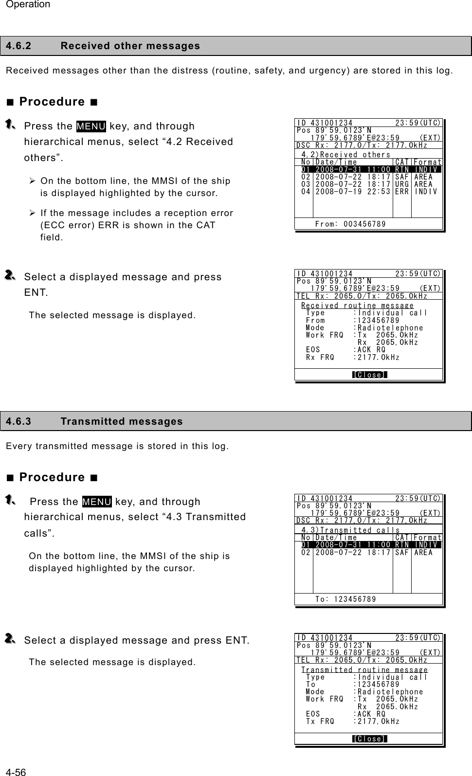
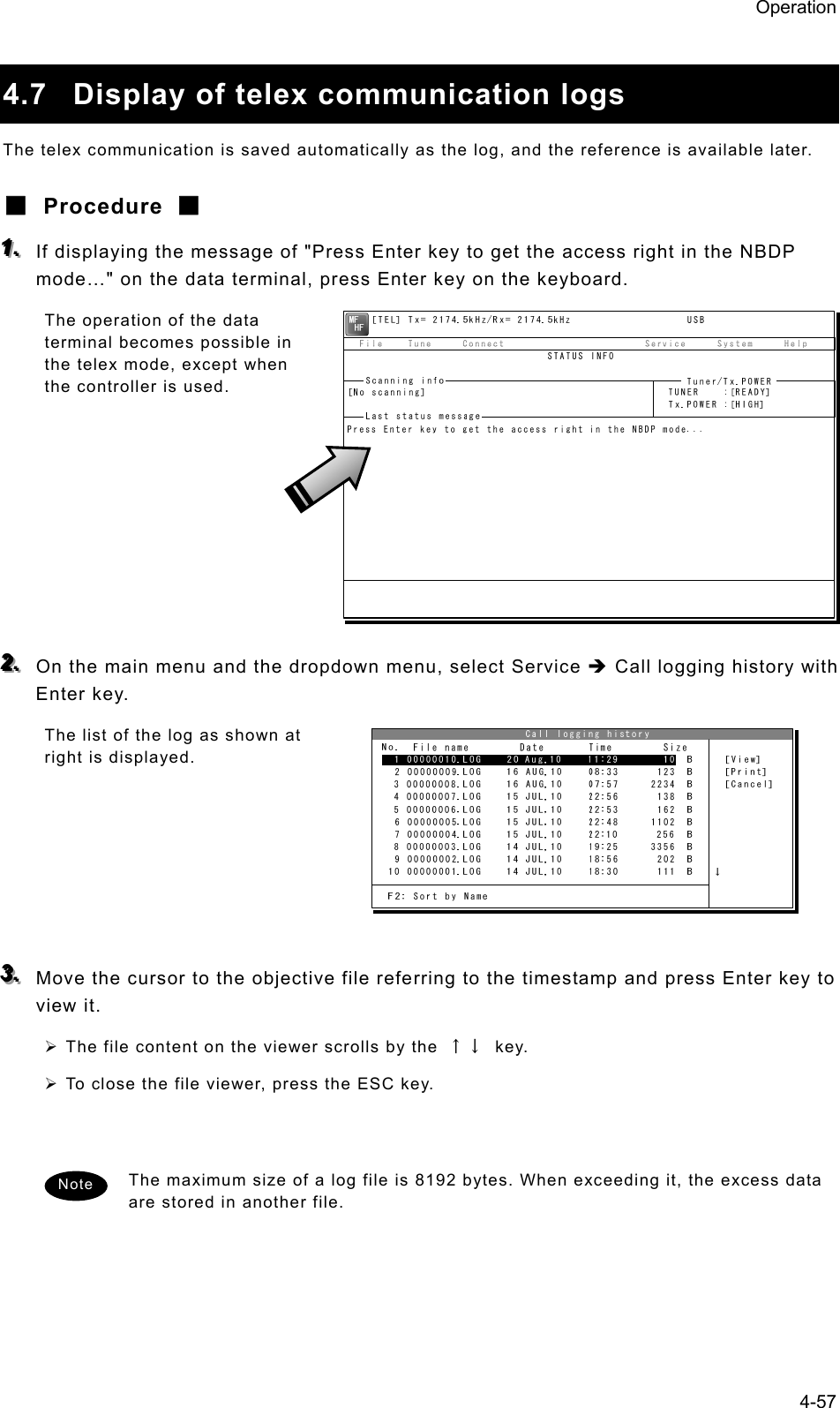
![Operation 4-58 4.8 USB memory operation This section describes how to use the USB memory. ・ The following conditions are required for the USB memory. Note) Not all USB memories satisfying the every condition are guaranteed. - The specification is complied with USB 1.1 or USB 2.0 standards. - No USB hub is built-in and is used to connect the USB memory. - No security function such as encryption or password to access is included. - No write-protect function is included, or that function is set to “Writable”. - Already formatted with FAT16 or FAT32 by Windows® OS. ・ Only the USB memory is connectable to the USB memory connector. ・ When the USB memory size is large, the file access time will be longer than small one. ・ The files or folders named with multibyte character prepared by other than the data terminal cannot be accessed. ・ If the USB memory is removed, always close the connector with the rubber cap to ensure the water-proof and dust-proof performance. ・ Initializing the USB memory will erase all data on the USB memory. ・ To avoid abnormal conditions, do not use the USB memory that has the broken file system. ■ Procedure ■ 111... If displaying the message of "Press Enter key to get the access right in the NBDP mode…" on the data terminal, press Enter key on the keyboard. The operation of the data terminal becomes possible in the telex mode, except when the controller is used. 222... After checking the USB mark indicating on the top of the display of the data terminal, select File from the main menu and the objective dropdown menu. ¾ To start either one of Edit existing file, Rename file, Delete file, or Copy file, input “A:” as the USB drive. ¾ To initialize the USB memory, select Initialize USB and operate in accordance with the message on the dialog box. ¾ To unmount the USB memory, select Remove USB and operate in accordance with the message on the dialog box. After completing the unmount and the USB mark of the top of the display is erased, the USB memory can be safely removed from the data terminal. Attention [TEL] Tx= 2174.5kHz/Rx= 2174.5kHz USB File Tune Connect Service System Help STATUS INFO[No scanning] TUNER :[READY] Tx.POWER :[HIGH]Press Enter key to get the access right in the NBDP mode...Scanning info Tuner/Tx.POWER Last status message](https://usermanual.wiki/Japan-Radio/JSS-2250/User-Guide-2169640-Page-110.png)
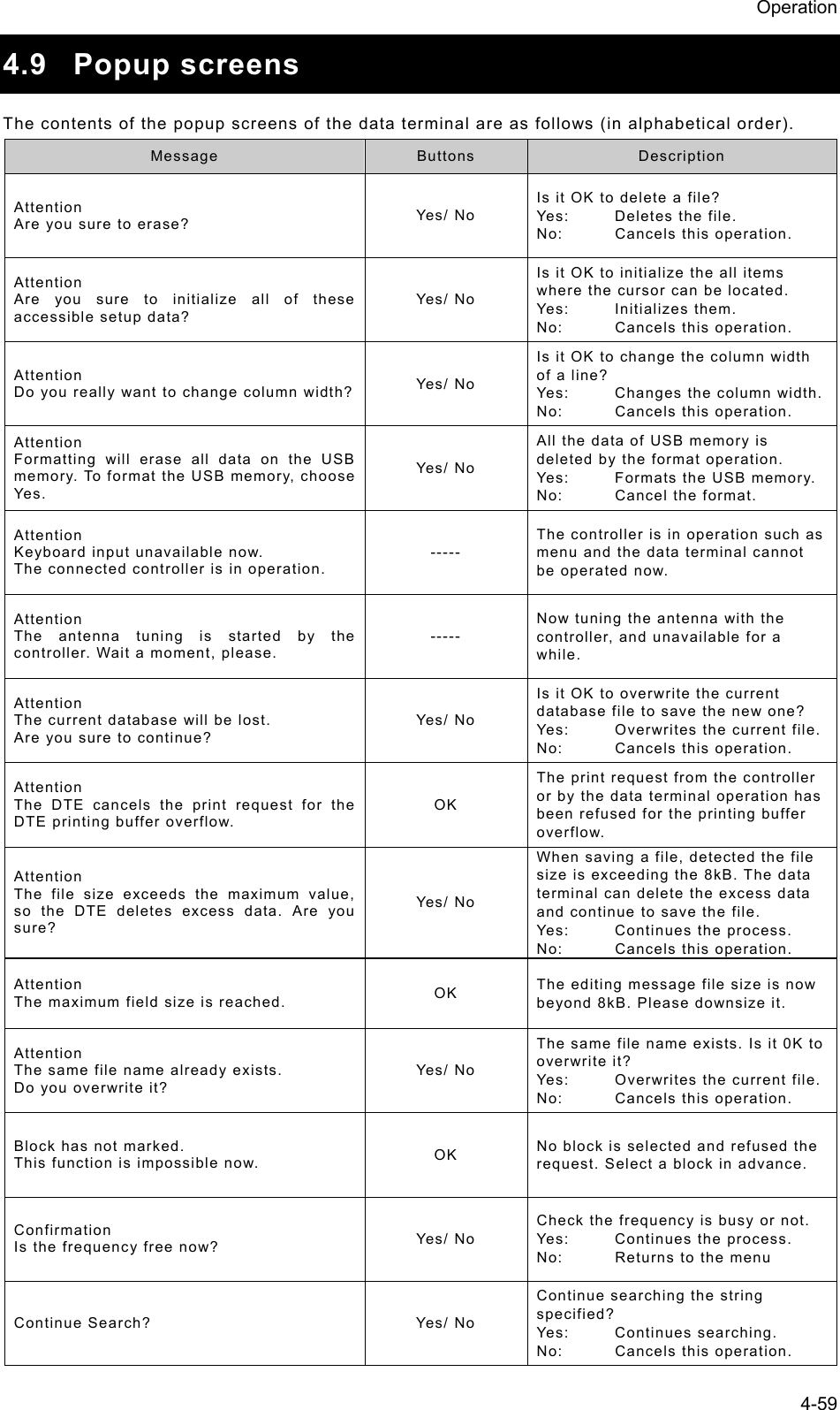
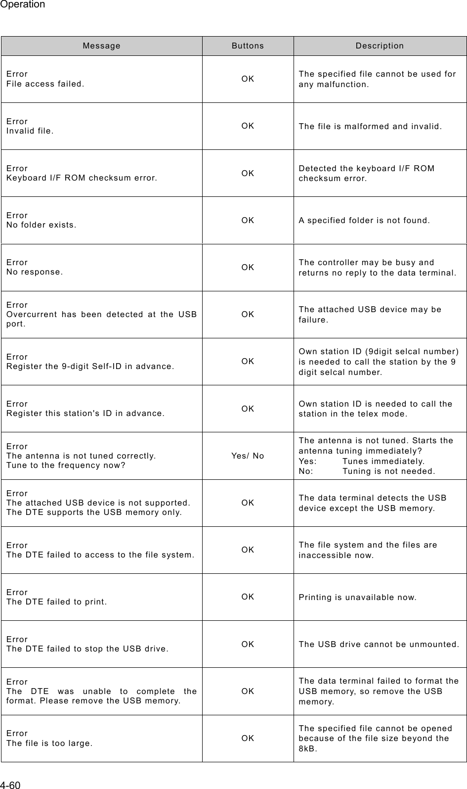
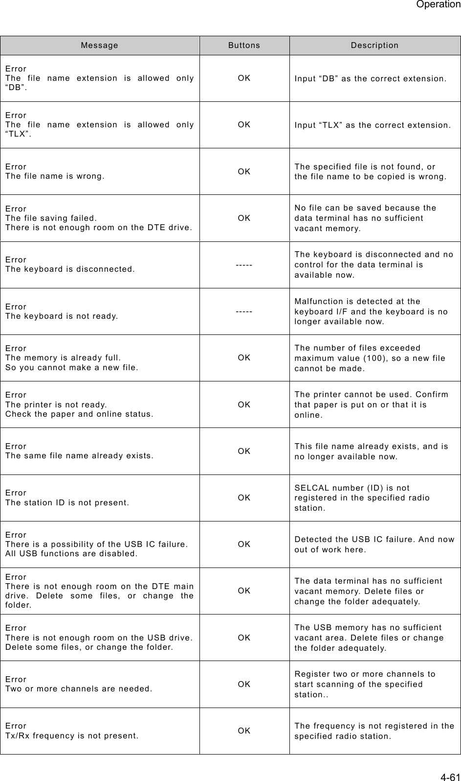
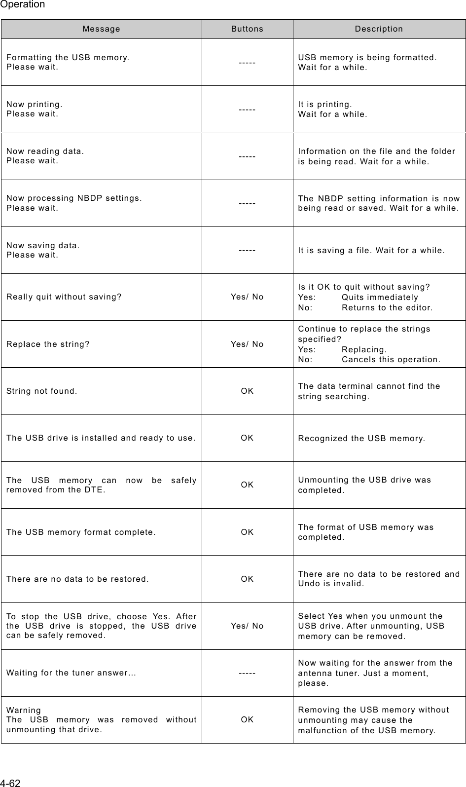
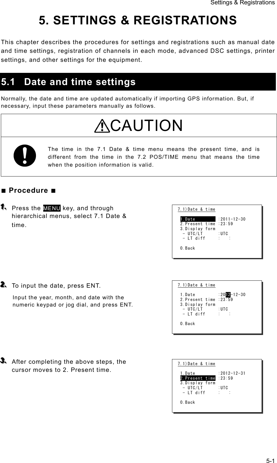
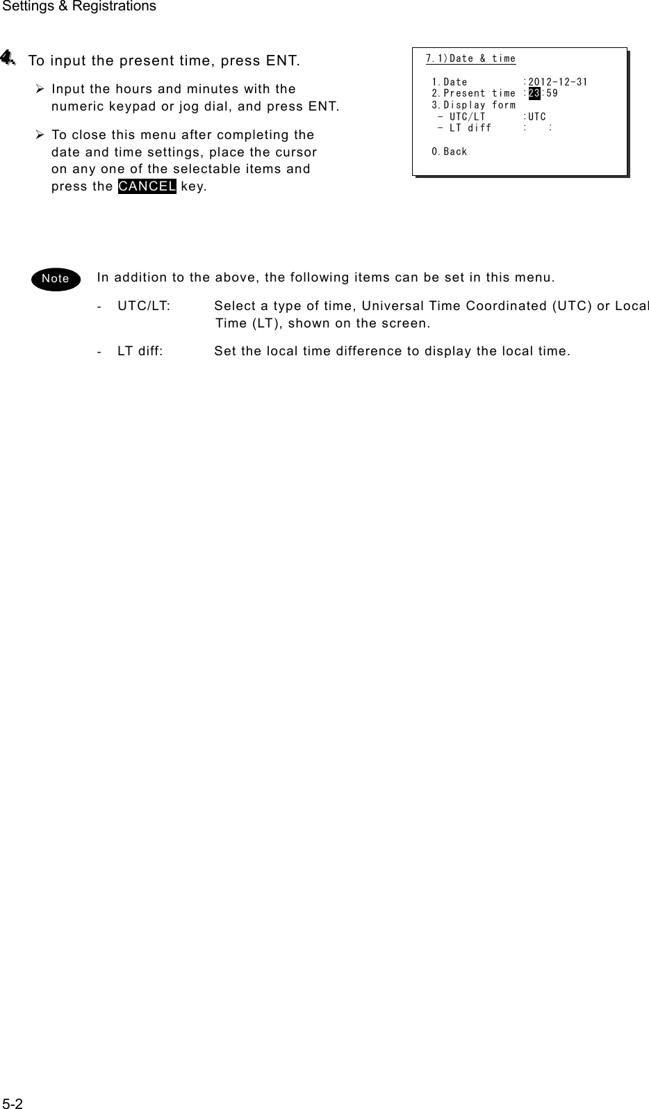
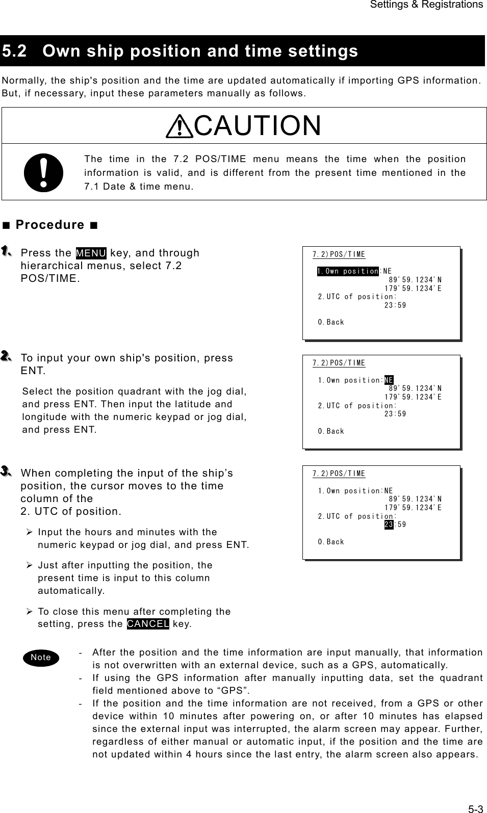
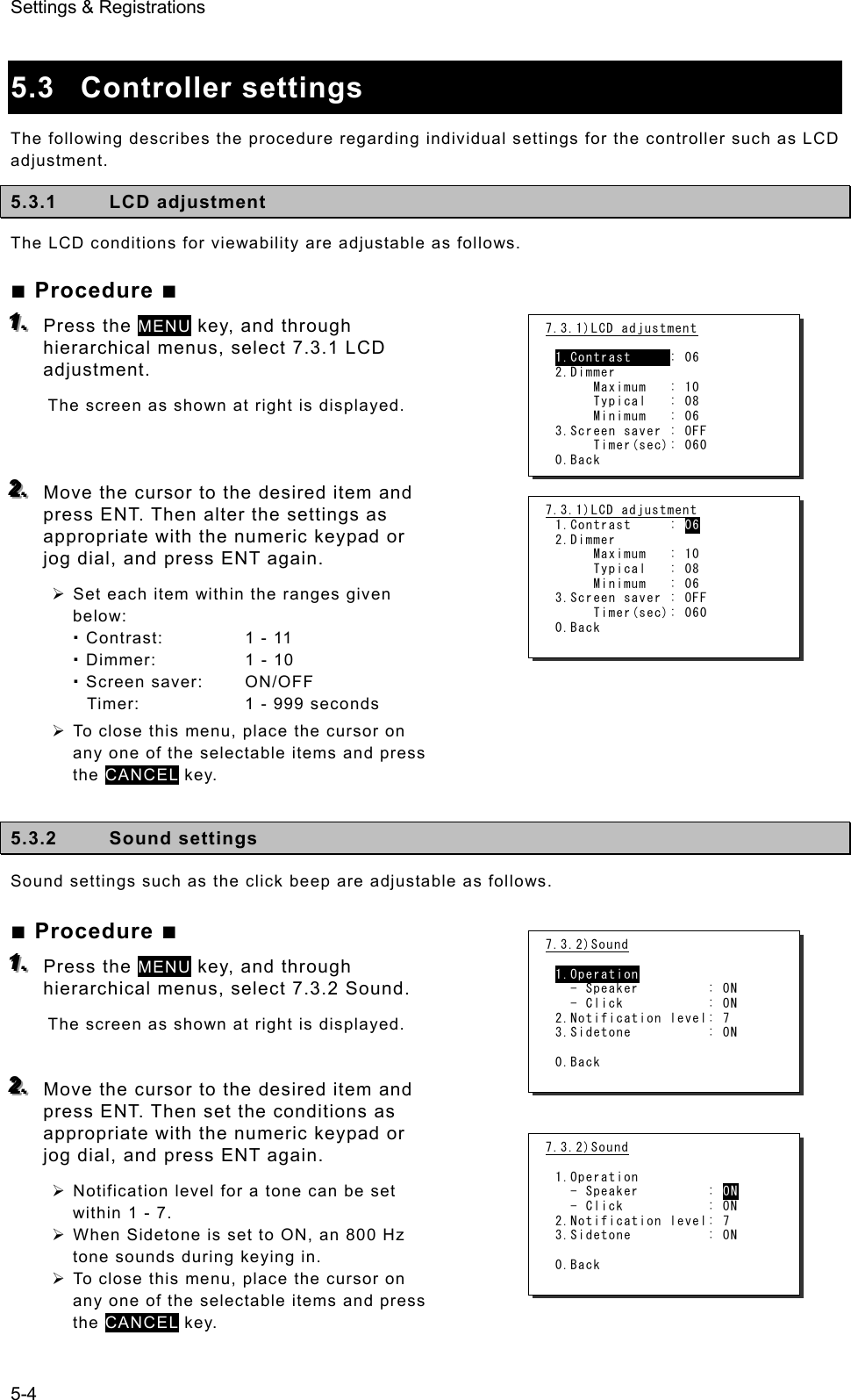
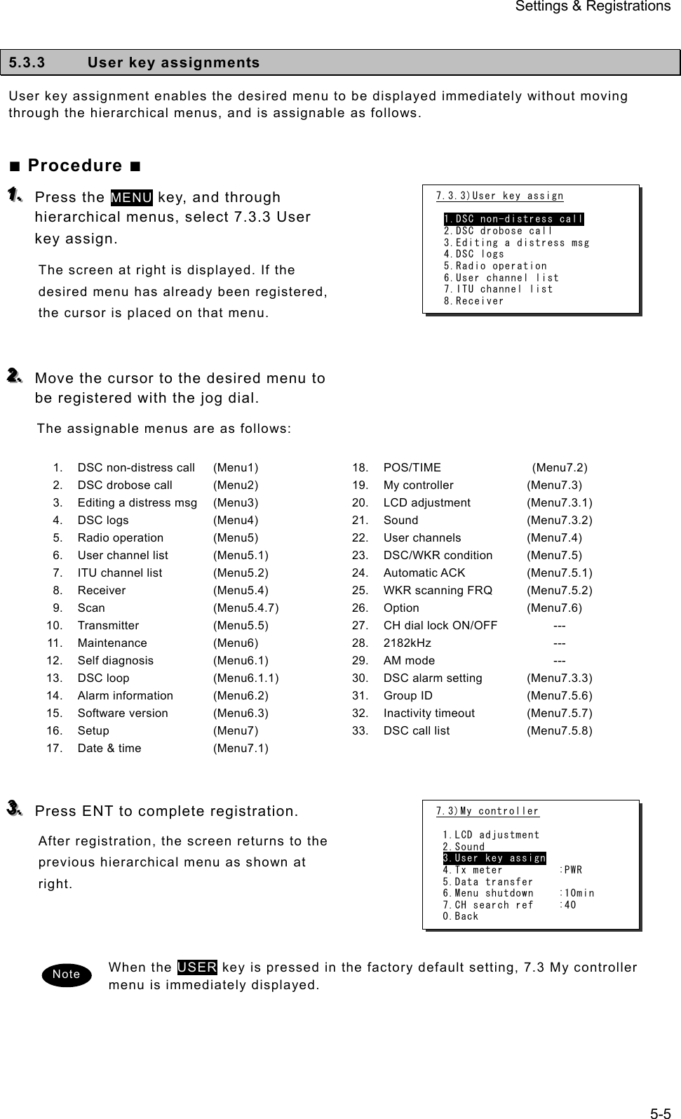
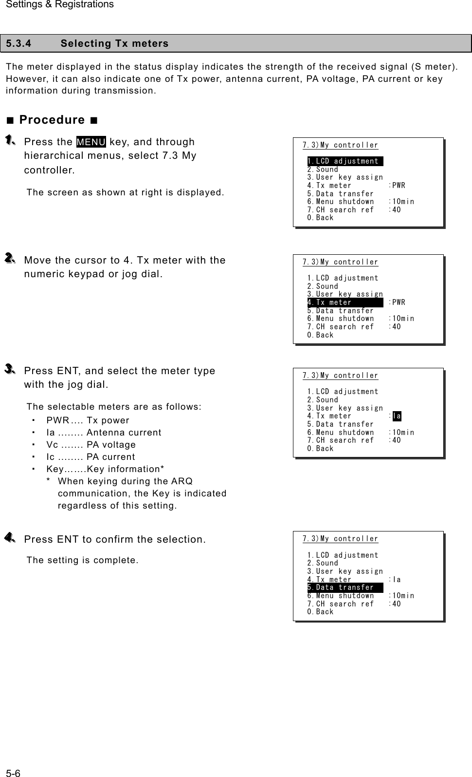
![Settings & Registrations 5-7 5.3.5 Transferring user channel data to another controller When 2 controllers are connected, stored information (user channel table) can be transferred from the controller having access rights to another controller (monitor condition). ■ Procedure ■ 111... Press the MENU key, and through hierarchical menus, select 7.3 My controller. 222... Move the cursor to 5. Data transfer with the numeric keypad or jog dial and press ENT. The popup screen as shown at right is displayed. 333... Press ENT to confirm the selection. ¾ The popup screen as shown at right is displayed to indicate the controller's status for forwarding. ¾ The screen at right (below) is displayed on the monitor. If OK is selected or the screen is left as it is for 10 seconds, transferring of stored information is started. 444... Forwarding of stored information is started. ¾ During forwarding, the popup screen as shown at right is displayed. ¾ The screen at right (below) is displayed on the monitor. ¾ The previous screen is returned to when forwarding is completed. To cancel forwarding midway, press the CANCEL key or ENT. Note [Display on monitor] OK to update this user channel table? [ OK ] [Cancel] [Display on monitor] Updating the table... [Cancel] 7.3)My controller 1.LCD adjustment 2.Sound 3.User key assign 4.Tx meter : Ia 5.Data transfer 6.Menu shutdown :10min 7.CH search ref :40 0.Back OK to transfer the user channels to another controller? [ OK ] [Cancel] 7.3)My controller 1.LCD adjustment 2.Sound 3.User key assign 4.Tx meter : Ia 5.Data transfer 6.Menu shutdown :10min 7.CH search ref :40 0.Back Wait a moment, please. 7.3)My controller 1.LCD adjustment 2.Sound 3.User key assign 4.Tx meter : Ia 5.Data transfer 6.Menu shutdown :10min 7.CH search ref :40 0.Back Data sending... [Cancel] 7.3)My controller 1.LCD adjustment 2.Sound 3.User key assign 4.Tx meter :PWR 5.Data transfer 6.Menu shutdown :10min 7.CH search ref :40 0.Back](https://usermanual.wiki/Japan-Radio/JSS-2250/User-Guide-2169640-Page-121.png)
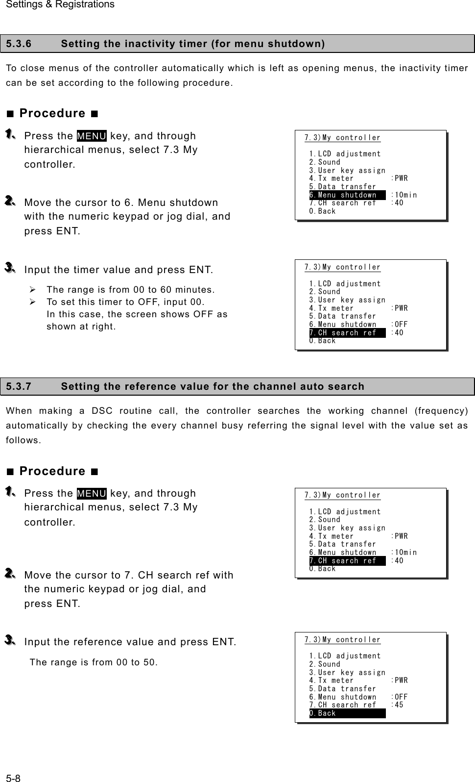
![Settings & Registrations 5-9 5.4 Registering user channels Often used frequencies at the controller for the radiotelephone, CW, and DSC mode can be registered as user channels and used in scanning radio settings or groups. A total of 20 groups with 20 channels set to each group (i.e. 400 channels) can be registered. Furthermore, the user channels of the telex frequency can be registered to the station list of the data terminal. ■ Procedure ■ 111... Press the MENU key, and through hierarchical menus, select 7.4 User channels (index). 222... Select the desired row or group to be edited with the numeric keypad or jog dial. The screen at right is displayed. (This example is for new registration to group 03.) Also, if an unregistered group is opened, TEL is displayed at Type as the default. 333... Press ENT to enter the group name. ¾ Up to 18 characters can be registered. ¾ The following characters are available: Alphabet (capital and small letters) Numbers 0 - 9 The following signs, space and determination symbol (◄) [ ] _ " # % & ' ( ) ? @ + - / = : ; < > ¾ Group names can be omitted. 444... Select a character and press ENT one by one. ¾ When inputting numbers with the numeric keypad ENT is not needed. ¾ To return to the previous letter, press the CANCEL key. ¾ To complete name entry of 18 characters long, press ENT after selecting the last character by the jog dial. Or, if the name is less than 18 characters long, following the name, select the determination symbol (◄), as shown at right and press ENT. The character sequence shown by turning the jog dial is as follows: ◄ A B C D E F G H I J K L M N O P Q R S T U V W X Y Z a b c d e f g h i j k l m n o p q r s t u v w x y z [ ] _ " # % & ' ( ) ? @ + - / = : ; < > 0 1 2 3 4 5 6 7 8 9 (space) Note 7.4)User channels (index) No CH group name Type 01 JRC Tokyo TEL 02030405060708Pacific ABC CW 7.4)User channels (table) Name: Type: TEL CHNo Rx[kHz] Tx[kHz] Mode 041 042 043 044 045 046 7.4)User channels (table) Name: ◄ Type: TEL CHNo Rx[kHz] Tx[kHz] Mode 041 042 043 044 045 046 7.4)User channels (table) Name: Japan Radio◄ Type: TEL CHNo Rx[kHz] Tx[kHz] Mode 041 042 043 044 045 046](https://usermanual.wiki/Japan-Radio/JSS-2250/User-Guide-2169640-Page-123.png)
![Settings & Registrations 5-10 555... After completing the above steps, the cursor returns to Type. ¾ If necessary, change the group attribute (communication mode or custom). ¾ The following attributes can be selected: TEL ··········· Radiotelephone mode DSC ··········· Digital selective calling mode CW ············ Continuous wave mode Custom Communication mode mix 666... When setting of group attributes is completed, the cursor returns to the topmost row of the channel number. (CHNo). 777... Select the channel number to register with the jog dial, and press ENT. Register as follows in the popup screen at right. ¾ When the group attribute is Custom, specify the communication mode at Mode. Otherwise, the communication mode is fixed to the mode specified at Type. ¾ To reference a frequency from the ITU channel, move the cursor to ITU channel, press ENT, and specify that channel number. ¾ Move the cursor to Rx freq(kHz), press ENT, and enter the Rx frequency. ¾ Move the cursor to Tx freq(kHz), press ENT, and enter the Tx frequency. 888... After completing the above steps, move the cursor to OK, and press ENT to complete registration. ¾ Follow the same procedure above to create a group of channels. ¾ Already registered channels can be changed by the above procedure. ¾ To close this menu, place the cursor on any one of the registration numbers, and press the CANCEL key. - To delete an already registered channel, move the cursor to Erase in the above popup screen, and press ENT. - To erase an already registered group, move the cursor to "000 ALL CLEAR function" in the bottommost row of the channel list, and press ENT. Next, move the cursor to OK in the confirmation screen, and press ENT. - To erase all already registered groups, move the cursor to "00 ALL CLEAR function" in the User channels (index) screen, and press ENT. Next, move the cursor to OK in the confirmation screen, and press ENT. - When the 7.6.1 Connection is set to DTE, the group 20 becomes the reserved group for telex channels of the data terminal and inaccessible at the controller. Note 7.4)User channels (table) Name: Japan Radio Type: TEL CHNo Rx[kHz] Tx[kHz] Mode 041 042 043 044 045 046 7.4)User channels (table) Name: Japan Radio Type: TEL CHNo Rx[kHz] Tx[kHz] Mode 041 042 043 044 045 046 7.4)User channels (table) Name: Japan Radio Type: TEL CHNo Rx[kHz] Tx[kHz] Mode 041 042 043 044 045 046 CHNo. 041/Type TEL Mode :TEL ITU Channel : Rx freq(kHz) : Tx freq(kHz) : [OK] [Cancel] [Erase] 7.4)User channels (table) Name: Japan Radio Type: TEL CHNo Rx[kHz] Tx[kHz] Mode 041 042 043 044 045 046 4071.0 4071.0 TEL](https://usermanual.wiki/Japan-Radio/JSS-2250/User-Guide-2169640-Page-124.png)
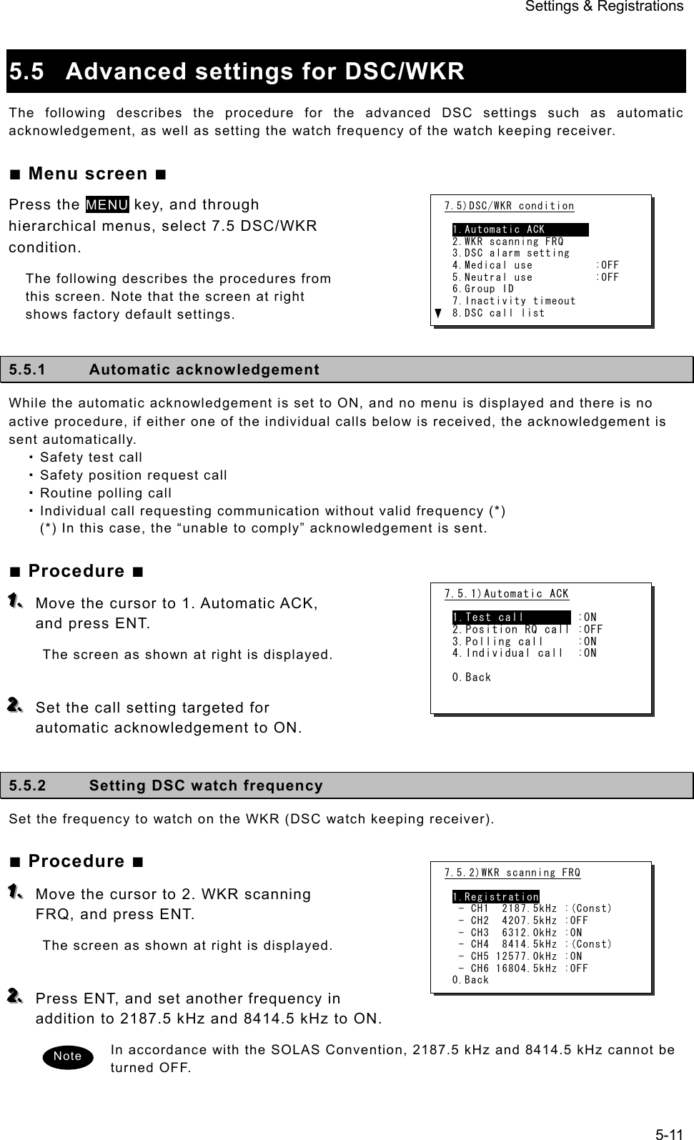
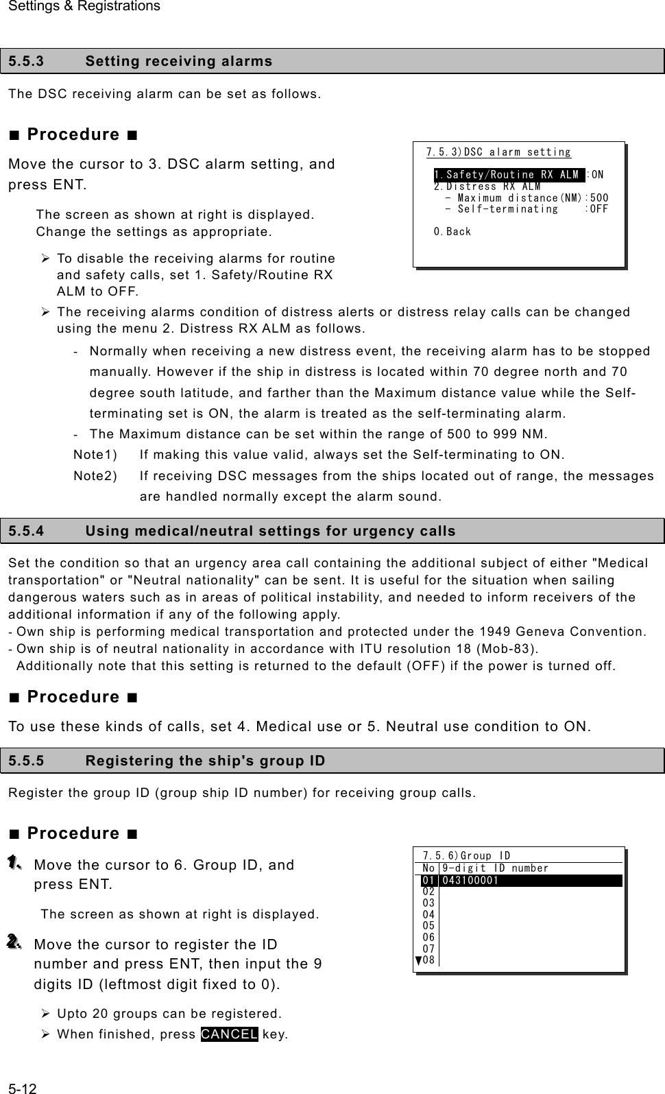
![Settings & Registrations 5-13 5.5.6 Setting the inactivity timer (for procedures on hold) When making a procedure on hold, the procedure is automatically terminated after the time set as follows. ■ Procedure ■ 111... Move the cursor to 7. Inactivity timeout, and press ENT. The screen as shown at right is displayed. Change the settings as appropriate. 1. ACKed distress alert The acknowledged distress alert events sent from the own ship: - The range is 00 (OFF) to 60 minutes. 2. RCVed other distress The distress events of other ships - The range is 00 (OFF) to 60 minutes. 3. Non-distress call Routine, safety and urgency events - The range is 00 (OFF) to 60 minutes. 4. Other communications Communications without using DSC - The range is 010 to 600 seconds. 5.5.7 Registering the DSC call list To call the station using the DSC, registers the station names, MMSI and the calling frequencies as follows. ■ Procedure ■ 111... Move the cursor to 8. DSC call list, and press ENT. The screen as shown at right is displayed. 222... Move the cursor to the line to be changed and press ENT to display the frequency list as shown at right. 333... Input data as appropriate using the numeric keypad or jog dial. ¾ Upto 20 channels for every 20 stations can be registered. ¾ When finished, press CANCEL key. 7.5.7)Inactivity timeout 1.ACKed distress alert:OFF 2.RCVed other distress:OFF 3.Non-distress call :15min 4.Other communications:030sec 0.Back 7.5.8)DSC call list No Station name MMSI 0102030405060708JRC Mitaka1 431000001 7.5.8)DSC call list(FRQ) Name:JRC Mitaka1 MMSI:431000001 No Rx[kHz] Tx[kHz] Category 010203040506 2177.0 4219.5 4220.0 4220.5 2189.5 4208.0 4208.5 4209.0 RTN RTN RTN RTN](https://usermanual.wiki/Japan-Radio/JSS-2250/User-Guide-2169640-Page-127.png)
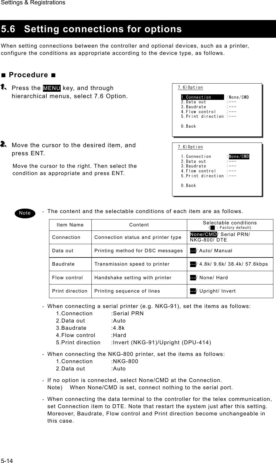
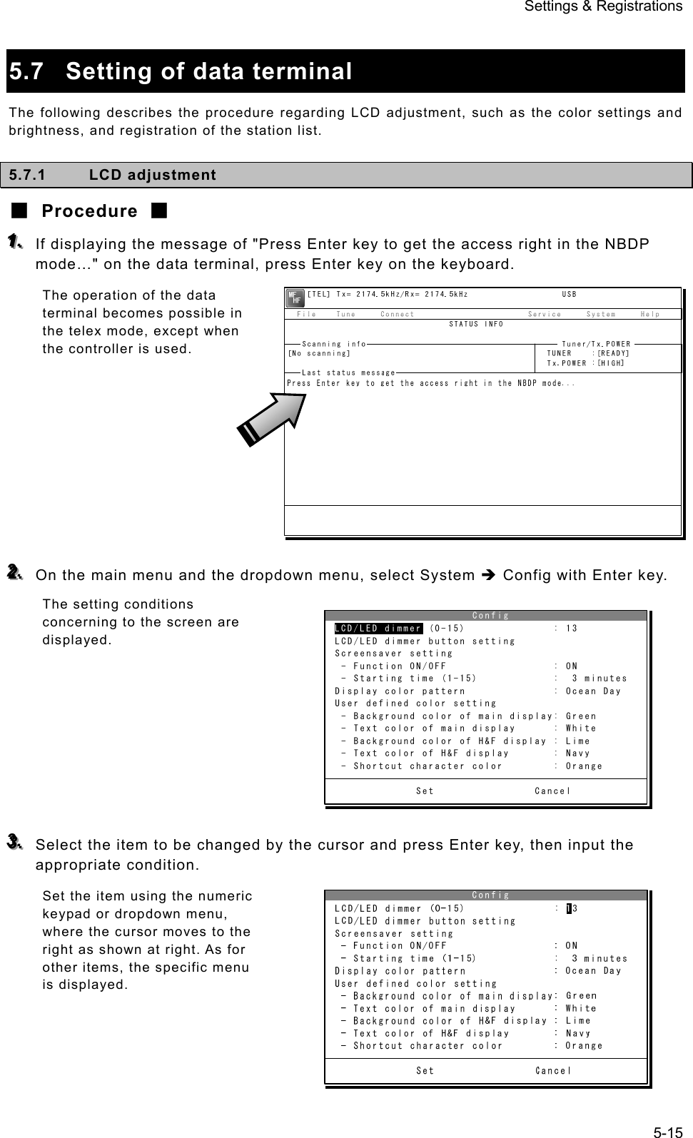
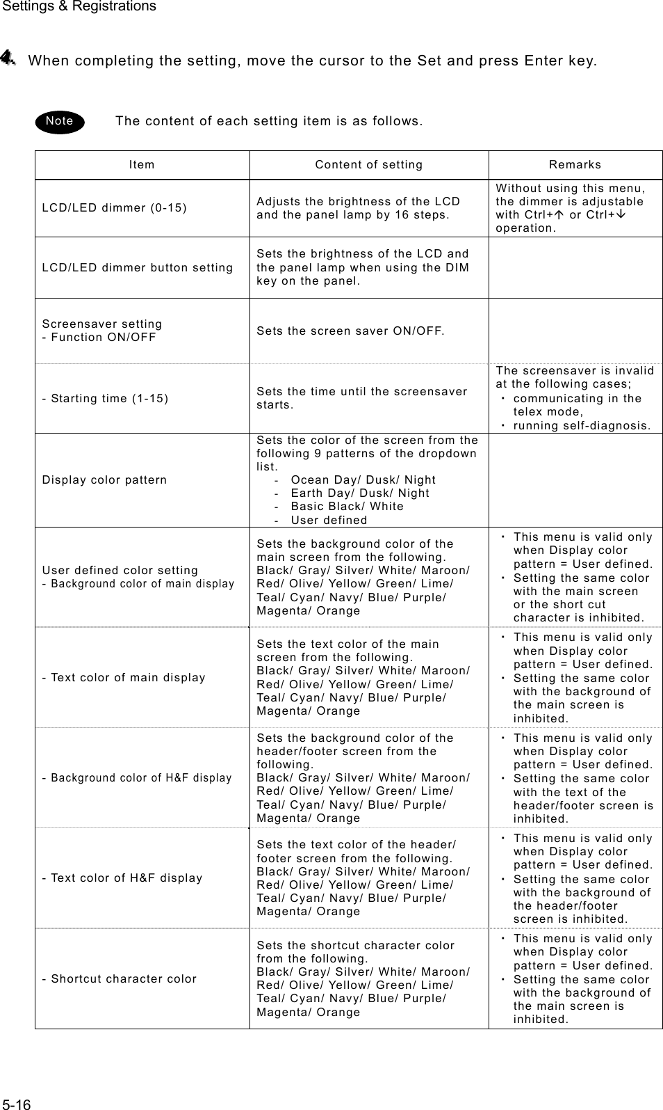
![Settings & Registrations 5-17 5.7.2 Registering station list ■ Procedure ■ 111... If displaying the message of "Press Enter key to get the access right in the NBDP mode…" on the data terminal, press Enter key on the keyboard. The operation of the data terminal becomes possible in the telex mode, except when the controller is used. 222... On the main menu and the dropdown menu, select Service Î Station list with Enter key. The station list is displayed. 333... Select the line to be registered newly or to be changed with the cursor and press Enter key. Then input the station information including the channels on the station list edit screen. ¾ Input the radio station name within 16 characters to Station Name column. (The @ character is unavailable.) ¾ Input 4 (coast station), 5 (ships station) or 9 digits SELCAL number to Station ID column. ¾ The Location and Free CH Sig are optional. ¾ Move the cursor to the line to be registered and press Enter key. Then input the Tx/Rx frequencies on the popup screen at right. 444... After inputting, press Enter key to close the screen and finish the registration. Station list No. Station Name ID Location F.Sig 1 Station 01 004310123 N33゚45' E138゚12' DOTDOT [Edit] 2 Station 02 004311234 N37゚22' E135゚51' DOTDOT [Erase] 3 Station 03 431012345 [Print] 4 [Cancel] 5 6 7 8 9 10 ↓ 1 Station 01 004310123 N33゚45' E138゚12' DOTDOT](https://usermanual.wiki/Japan-Radio/JSS-2250/User-Guide-2169640-Page-131.png)
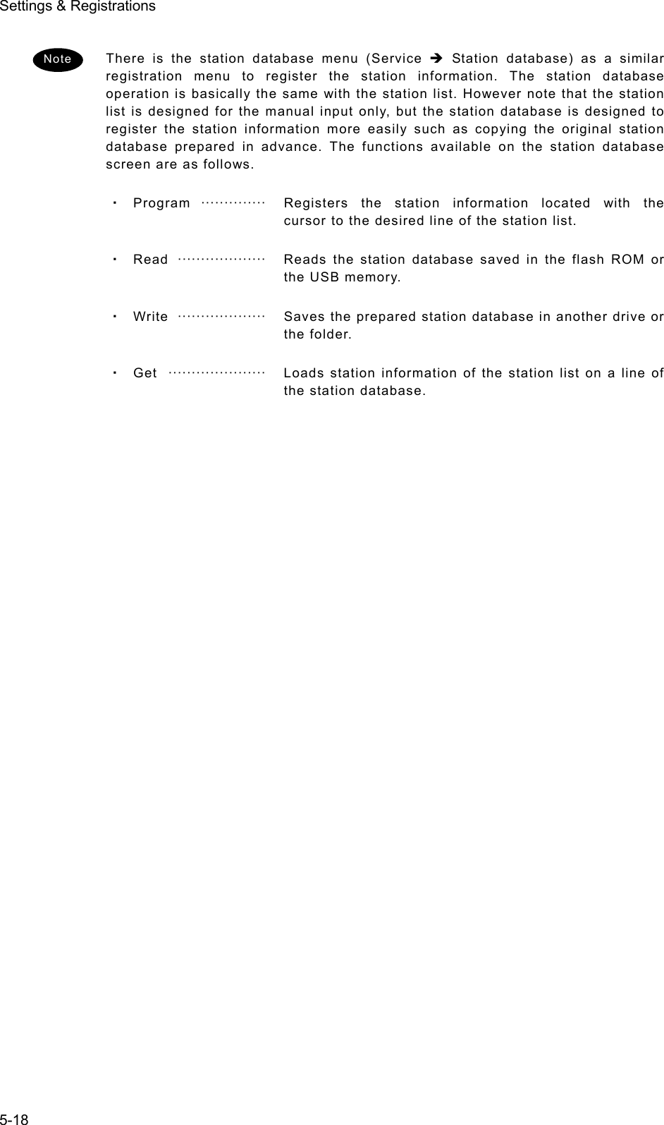
![Settings & Registrations 5-19 5.8 Setting telex mode The following describes the procedure to check or set the condition for the telex communication. ■ Procedure ■ 111... If displaying the message of "Press Enter key to get the access right in the NBDP mode…" on the data terminal, press Enter key on the keyboard. The operation of the data terminal becomes possible in the telex mode, except when the controller is used. 222... On the main menu and the dropdown menu, select System Î NBDP setup with Enter key. The setting conditions concerning to the telex communication are displayed. 333... Select the item to be changed with the cursor, and press Enter key. The input screen as shown at right is displayed. ※ An example of Max. FEC error rate 444... Press Enter key to move the cursor to the right. Then input the value and press Enter key again. The cursor moves to Set. Setup data input Max. FEC error rate : [ 30] % Input range is from 1 to 100. Set CancelMax. FEC error rate Setup data input Max. FEC error rate : [ 30] % Input range is from 1 to 100. Set CancelSet](https://usermanual.wiki/Japan-Radio/JSS-2250/User-Guide-2169640-Page-133.png)
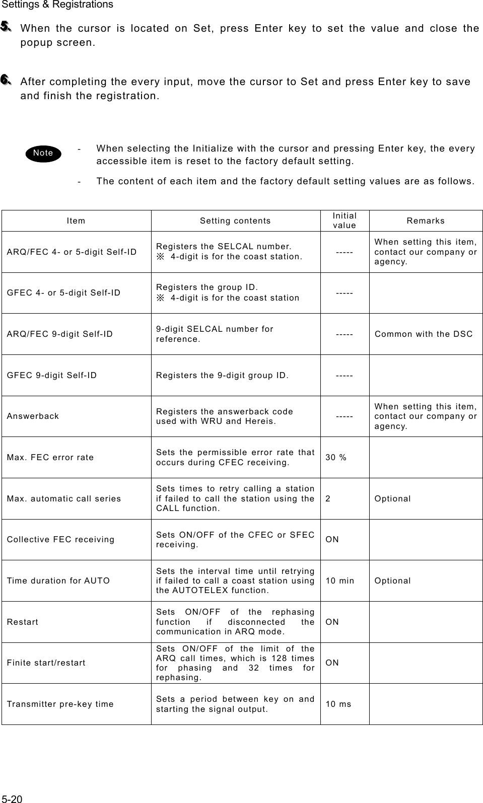
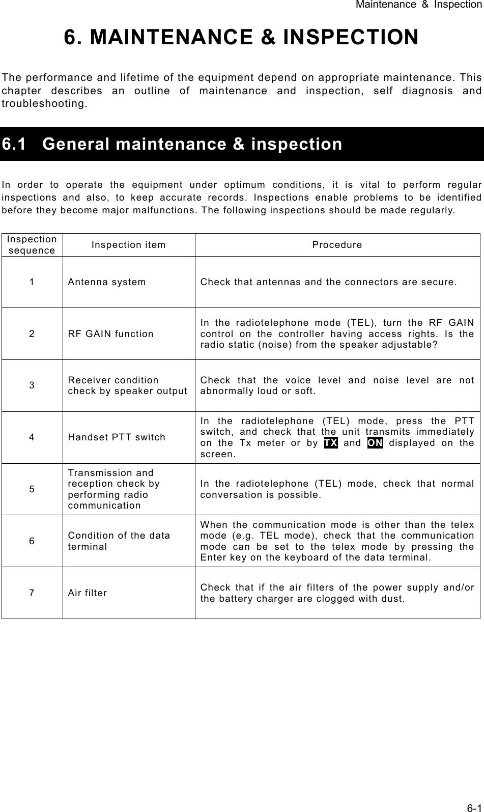
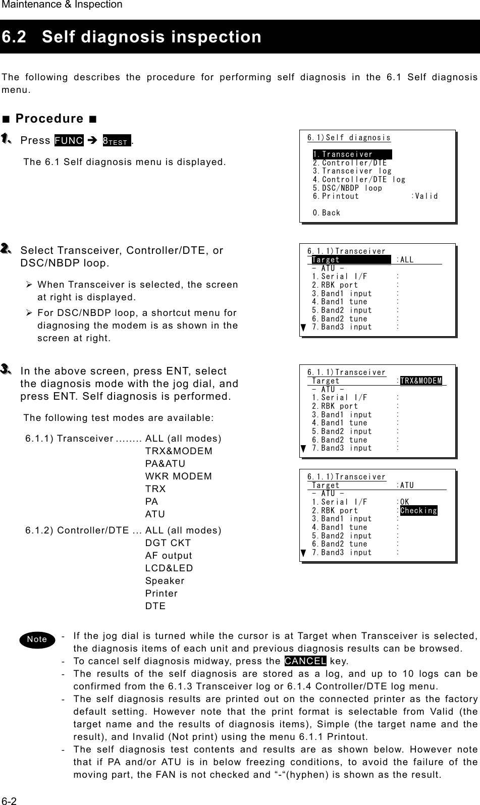
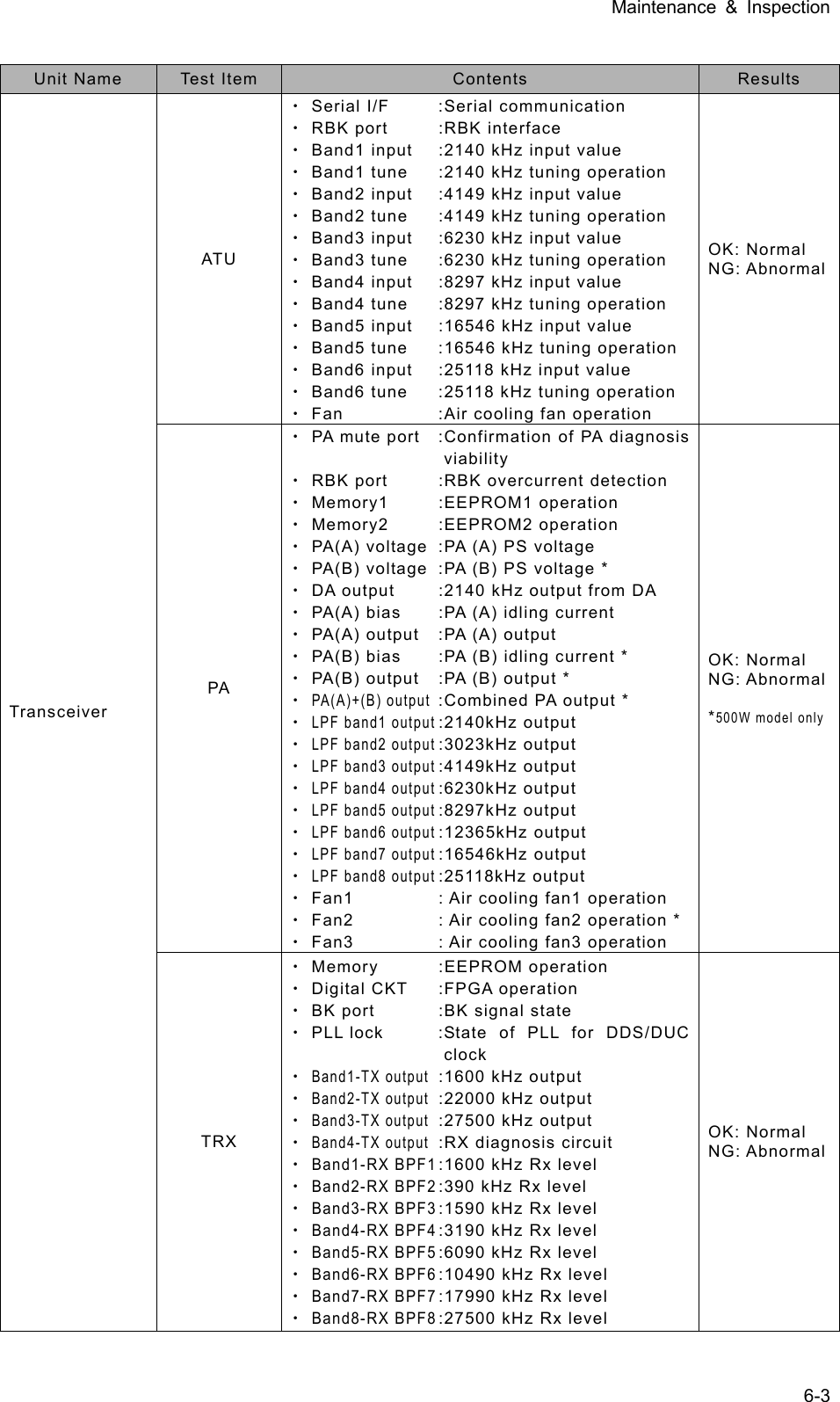
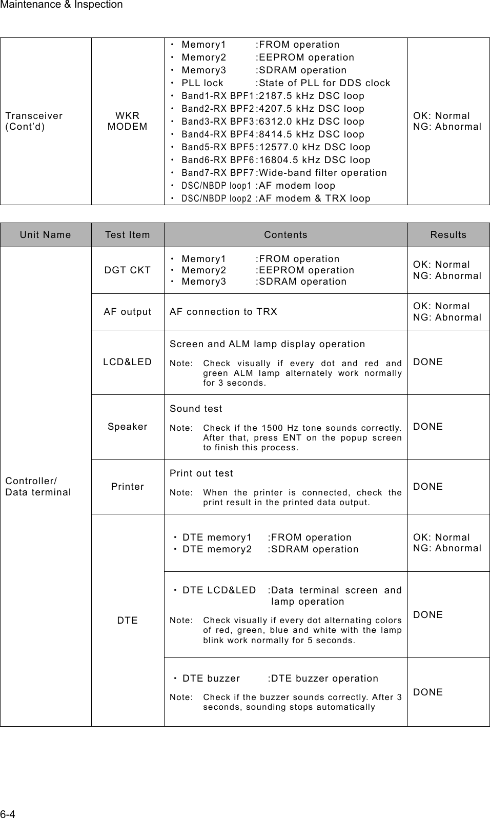
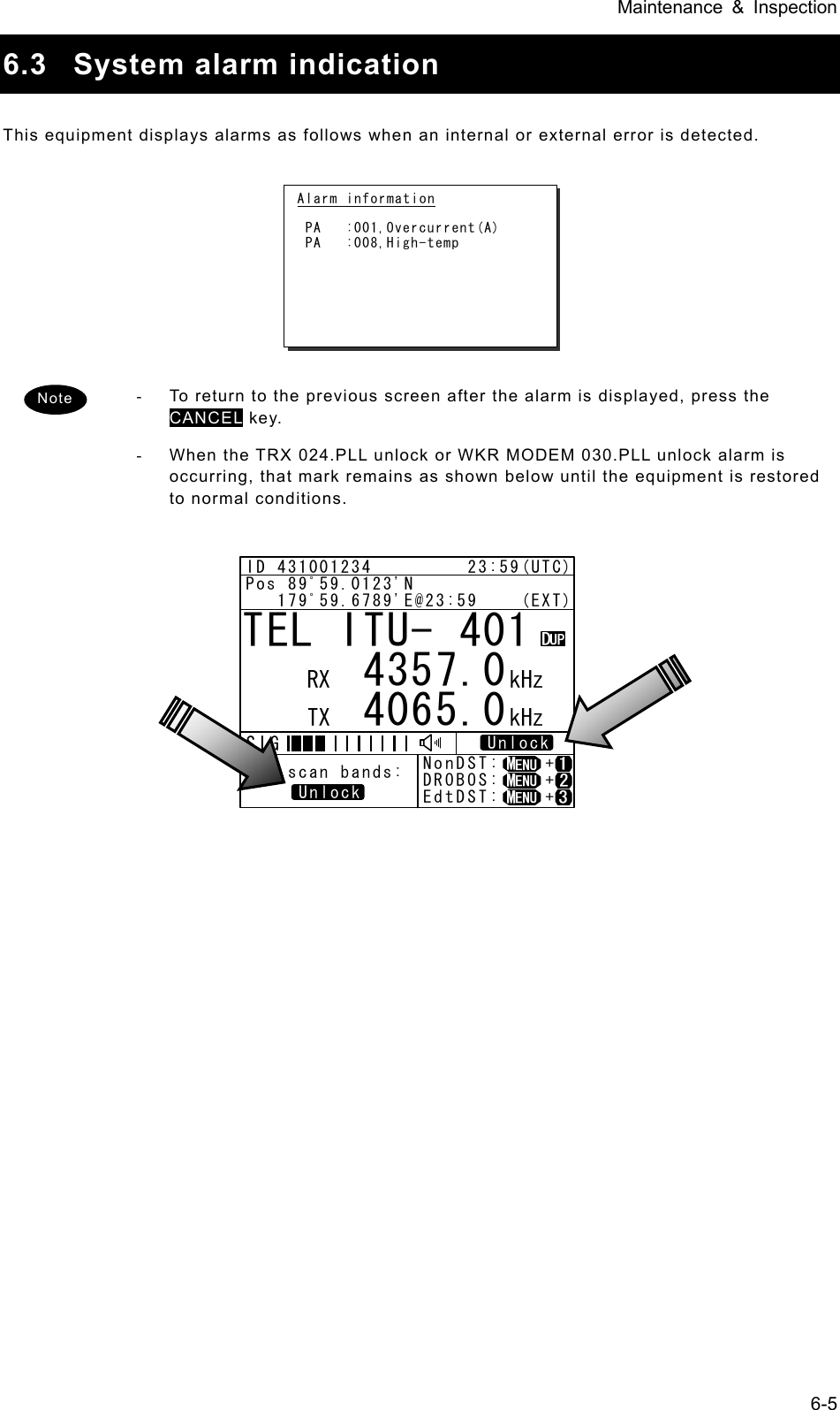
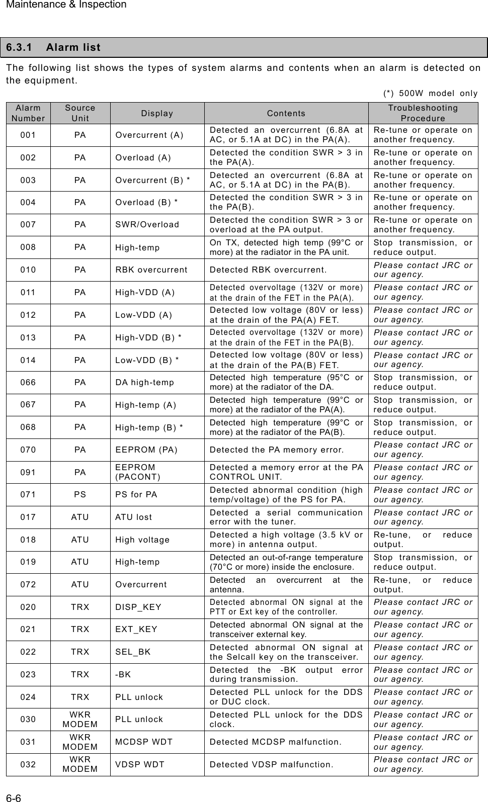
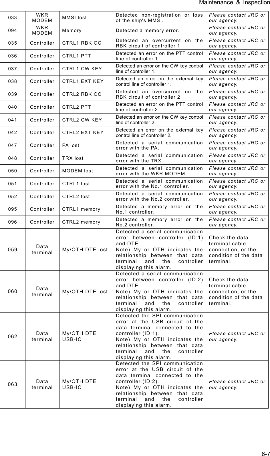
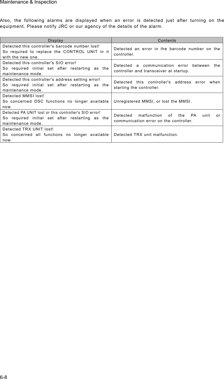
![Maintenance & Inspection 6-9 6.3.2 Viewing the alarm history The following describes how to view alarm information detected by the equipment or a history of past occurring alarms in the 6.2 Alarm information menu. ■ Procedure ■ 111... Press the MENU key, and through hierarchical menus, select 6.2 Alarm information. One of the screens shown at right is displayed indicating if an alarm is occurring. The displayed alarm information is formatted as follows. [Unit Name] : [Alarm Number], [Information] 222... To check the alarm history, press ENT. The popup screen at right is displayed, select OK. 333... The alarm history is displayed. Up to 100 of the latest histories are stored. If necessary, scroll with the jog dial. The displayed alarm history is formatted as follows. [Number] [Alarm & recovery time] [A: Alarm/V: Recovery] [Unit name] : [Alarm number], [Information] 6.2)Alarm information No data Press ENT to view alarm history.(If there is an alarm) Note Note (If there is no alarm) 6.2)Alarm information No data Press ENT to view alarm history. View alarm history? [ OK ] [Cancel] Alarm history 1.2008-12-31 23:59 A PA :001,Overcurrent(A) 2.2008-12-31 23:59 A PA :008,High-temp 3.2008-11-30 22:45 V ATU :019,High-temp 4.2008-11-28 22:11 V ATU :018,High voltage 6.2)Alarm information PA :001,Overcurrent(A) PA :008,High-temp Press ENT to view alarm history.](https://usermanual.wiki/Japan-Radio/JSS-2250/User-Guide-2169640-Page-143.png)
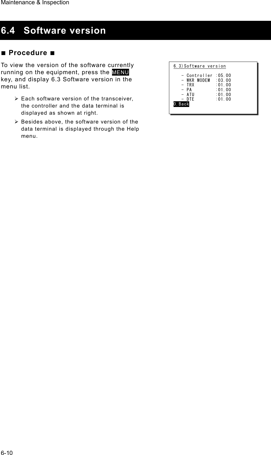
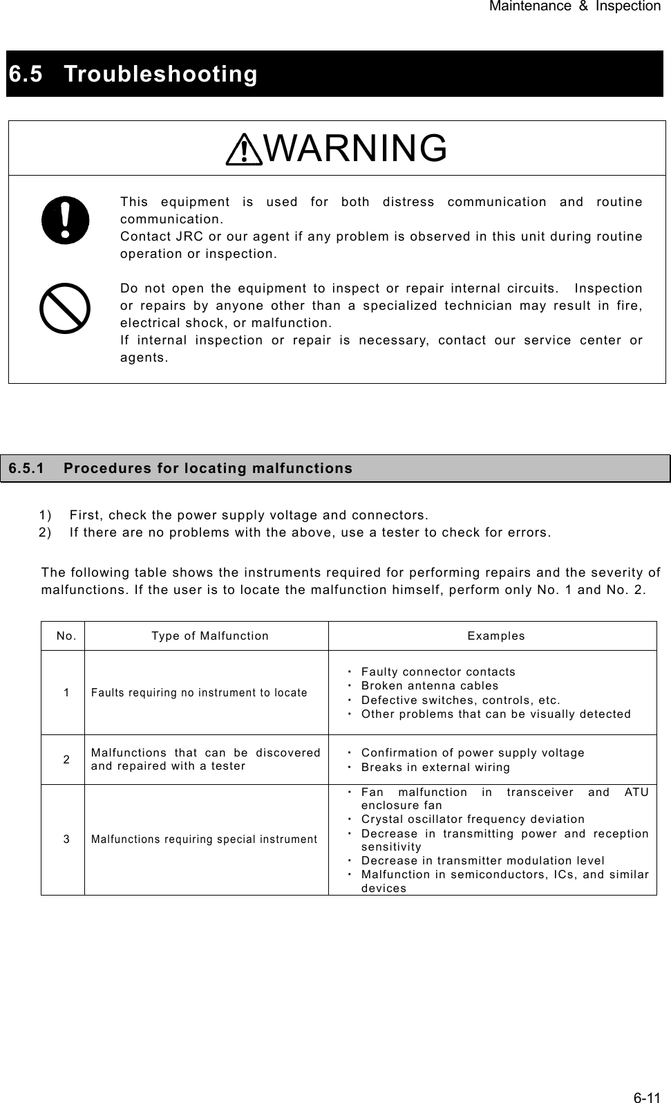
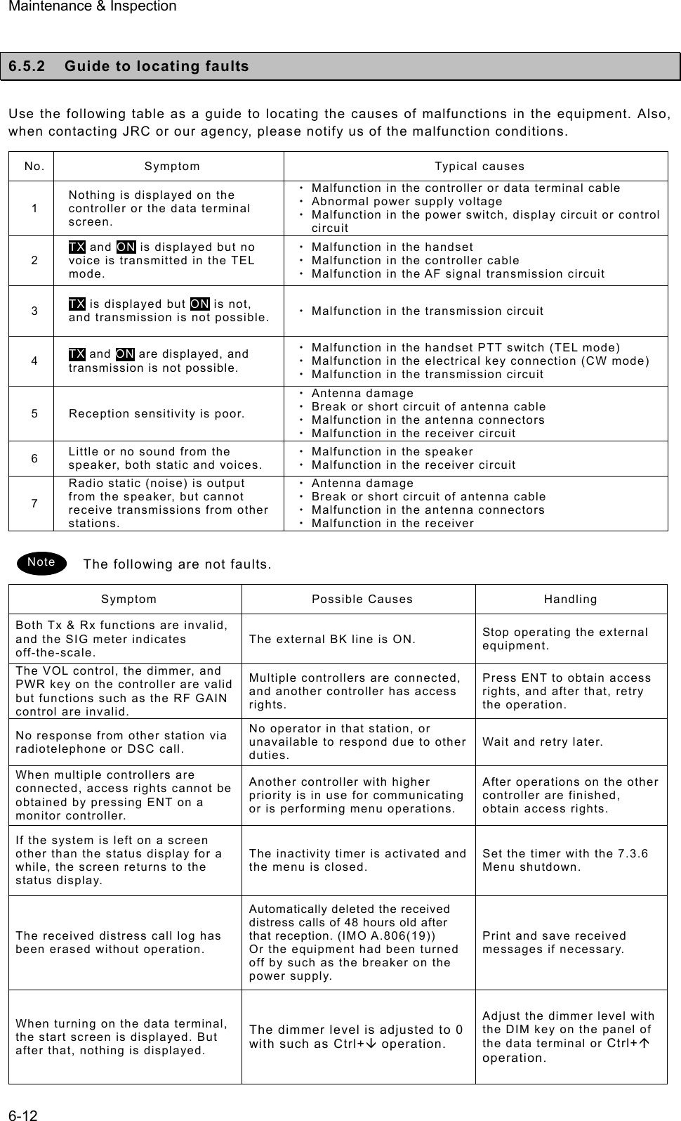
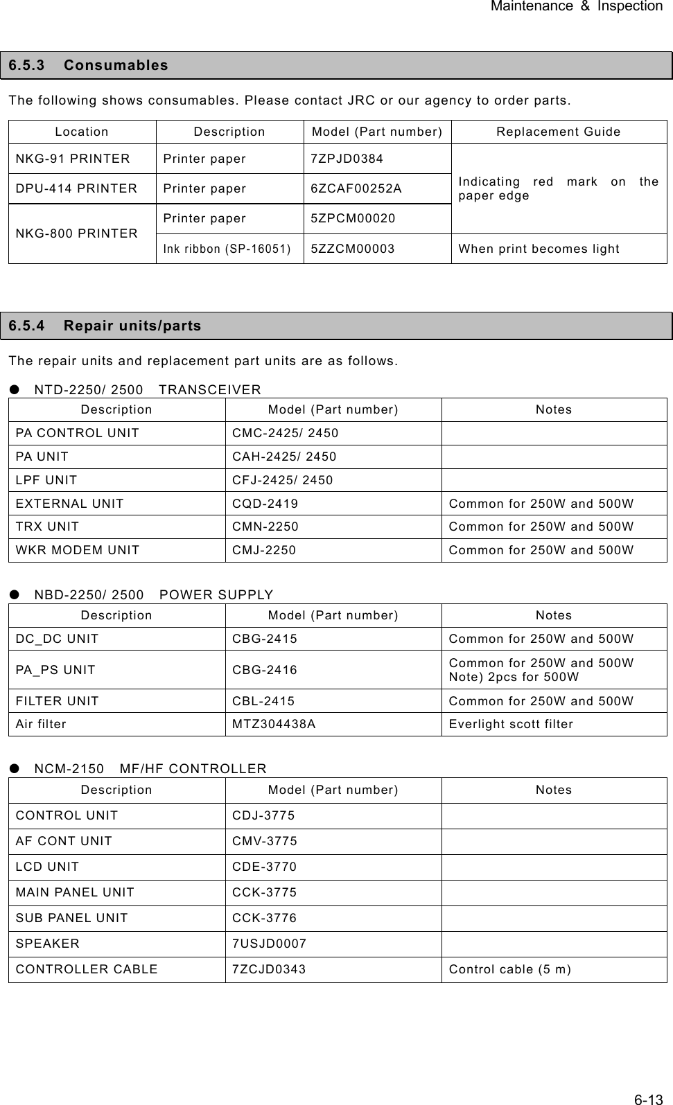
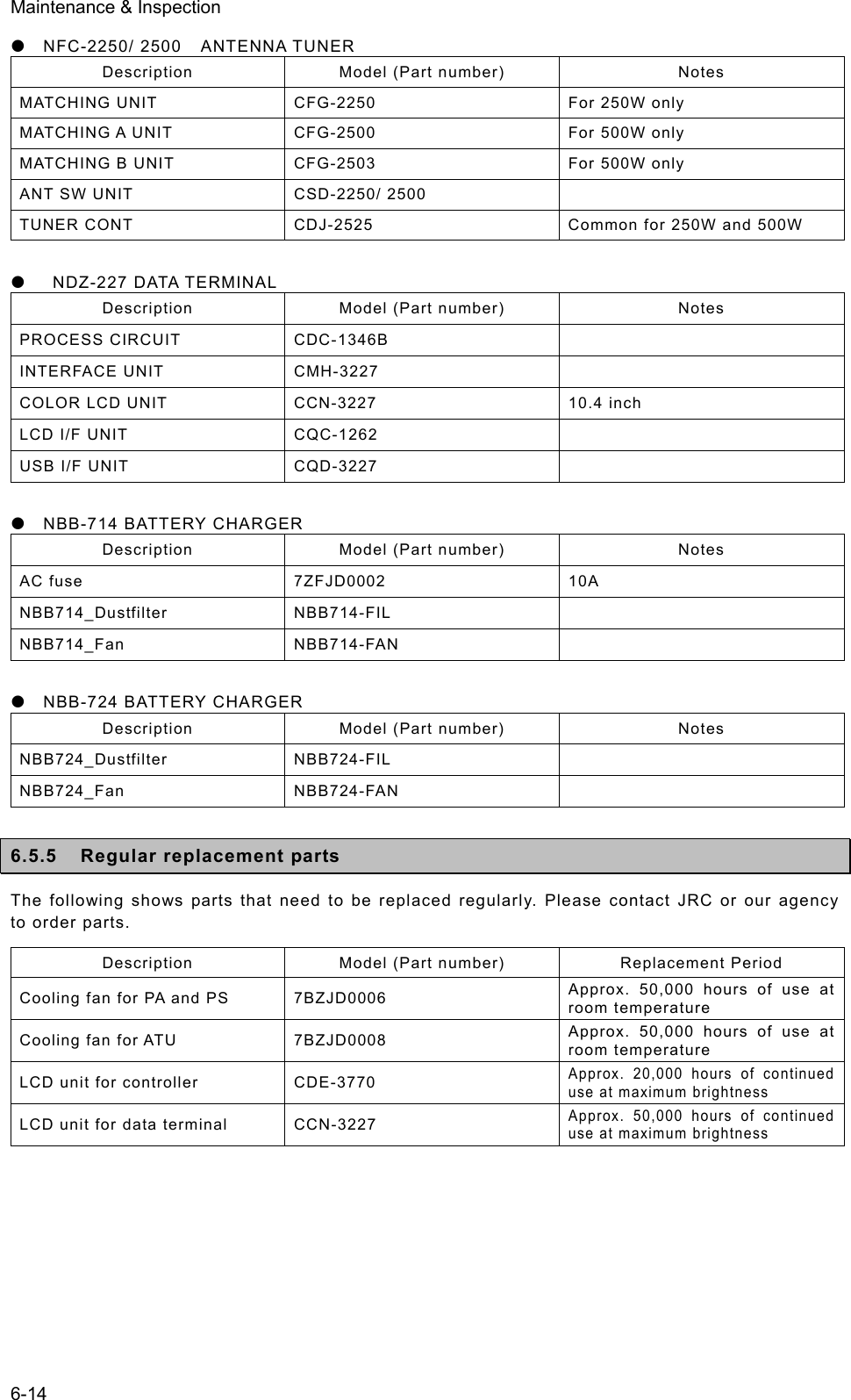
![Specifications 9-1 9. SPECIFICATIONS 9.1 JSS-2250/2500 MF/HF Radio Equipment z General Specifications Transmission frequency 1605.0 - 27500.0 kHz (100 Hz steps) Reception frequency 90.0 - 29999.9 kHz (100 Hz steps) Frequency stability Within ±10 Hz Type of emission TEL mode : J3E DSC/TLX mode : F1B CW mode : A1A AM mode : H3E H2B mode : H2B DATA mode : J2D Channels User channels (TEL/DSC/CW) : Max. 400 ch (20 ch x 20 grp) User channels (TLX) : Max. 400 ch (20 ch x 20 sta) ITU preset channels : 1722 ch Scan channels Max. 20 channels (group specification method) Nominal frequency J3E/ A1A/ H3E/ H2B/ J2D : Carrier frequencies F1B : Assigned frequency Communication method in TEL Push-to-talk (simplex, semi-duplex) Antenna impedance 50 unbalanced Channel switching duration 15 sec or less Interface IEC61162-1 (GPS/AME/RMS) Compass safety distance 2.0 m Main controls DSC call (sending and receiving), communication freq/ channel settings, Tx power settings, RF gain adjustment, volume adjustment, LCD adjustment Performance criteria IMO A.806(19), A.694(17), MSC68(68), MSC/Circ.862 IEC 60945 Ed.4 2002-08 Power supply voltage 90 VAC to 132 VAC, 180 VAC to 264 VAC 24 VDC (21.6 VDC to 31.2 VDC) Current consumption (JSS-2250/ 2500) Transmission AC : 2kVA / 3kVA 24VDC : 40A / 40A Reception AC : 0.5kVA / 0.5kVA 24VDC : 6A / 6A Operating temperature range -30 to +55oC (-15 to +55 oC during normal operation) Storage temperature range -30 to +55°C (parts exposed to condensation -30 to +70°C) Humidity resistance No abnormality after standing 10 hours in +40°C, 93%RH Vibration resistance (3 axes) 2 Hz - 5 Hz to 13.2 Hz : Full amplitude ±1 mm±10% 13.2 Hz to 100 Hz : Max acceleration 7 m/s2 fixed No abnormality after testing resonance points or at 30 Hz for 2 hours Continuous operation (TEL) No abnormality after operating continuously for 8 hours Continuous operation (DSC,WKR) No abnormality after operating continuously for 24 hours Category type of the weather resistance Antenna tuner and the junction box : Exposed Other units : Protected Protection rating IP22 equivalent (controller panel) Dimensions and mass (approx) (JSS-2250/ 2500) Main unit (Incase of the NCU-515A Rack) 520mm(W) x 665mm(H) x 450mm(D) [ex. projections], 90kg/96kg Antenna tuner 395mm(W) x 622mm(H) x 198mm(D) [ex. projections], 10kg/10kg MF/HF controller 230mm(W) x 142mm(H) x 89mm(D) [ex. projections], 1.3kg Data terminal 336mm(W) x 244mm(H) x 88mm(D) [ex. projections], 4.6kg](https://usermanual.wiki/Japan-Radio/JSS-2250/User-Guide-2169640-Page-151.png)
![Specifications 9-2 z Transmitter Antenna output power (JSS-2250/ 2500) 1605.0 - 3999.9 kHz AC : 200Wpep / 400Wpep 24VDC : 100Wpep / 100Wpep 4000.0 - 27500.0 kHz AC : 250Wpep / 500Wpep 24VDC : 150Wpep / 150Wpep Modulation method Low-power stage balanced modulation Occupied bandwidth J3E/ J2D/ H2B : Within 3 kHz F1B/ A1A : Within 0.5 kHz Carrier suppression (J3E) 40 dB or more Unwanted emissions in the out-of-band domain (JSS-2250/ 2500) Mean power of 50 mW or lower, or 67/70 dB or more lower than the mean power of the basic frequency Unwanted emissions in the spurious domain JSS-2250/2500 At J3E: 1.5 to 4.5 kHz : 28/28 dB or more 4.5 to 7.5 kHz : 35/35 dB or more 7.5 kHz and upwards : 64/67 dB or more At F1B: 0.25 to 0.5 kHz : 28/28 dB or more 0.50 to 1.25 kHz : 35/35 dB or more 1.25 kHz and upwards : 67/70 dB or more And following Mistuned frequency [Hz]Attenuation [dB] Overall distortion and noise -20 dB or less AF frequency response Deviation is within 6 dB in 350 Hz to 2700 Hz range. Tone frequency 1500 Hz or 1400 Hz z Receiver Receiving system Double superheterodyne 1st IF 70.036 MHz 2nd IF 36 kHz Reception frequency stability Within ±10 Hz Sensitivity (SINAD 20dB) J3E : 2.5 uV or less (1605.0 to 27500.0 kHz) F1B : 0.7 uV or less (1605.0 to 27500.0 kHz) A1A : 1.4 uV or less (1605.0 to 27500.0 kHz) Pass band/Adjacent signal selectivity J3E : 2.4 - 3.0 kHz (6 dB bandwidth) within ±2.1 kHz (66 dB bandwidth) F1B : 270 - 300Hz (6 dB bandwidth) within ±550 Hz (60 dB bandwidth) Spurious response J3E : 60 dB or more F1B : Symbol error rate of 1% or better at a wanted signal level of 10 uV and an unwanted signal level of 31.6 mV separated by 750 Hz Blocking/Desensitization J3E : When an unwanted signal level separated by 3 kHz is added to the wanted signal level of 10 uV, the unwanted signal input voltage suppressing output of the wanted signal by 3 dB is 10 mV or more. F1B : Symbol error rate of 1% or better at a wanted signal level of 10 uV and an unwanted signal level of 1 mV separated by 500 Hz](https://usermanual.wiki/Japan-Radio/JSS-2250/User-Guide-2169640-Page-152.png)