Japan Radio JSS-2500 Marine MF/HF GMDSS Radio Transceiver, digital selective calling (DSC) / narrow-band direct printing (NBDP) Modem User Manual
Japan Radio Co Ltd. Marine MF/HF GMDSS Radio Transceiver, digital selective calling (DSC) / narrow-band direct printing (NBDP) Modem
User Manual

MF/HF RADIO EQUIPMENT
Instruction Manual
7ZPJD0622
.

CAUTIONS AGAINST HIGH VOLTAGE
Radio and radar devices are operated by high voltages of anywhere from a few hundred volts up to
many hundreds of thousands of volts. Although there is no danger with normal use, it is very
dangerous if contact is made with the internal parts of these devices. (Only specialists should attempt
any maintenance, checking or adjusting.)
There is a very high risk of death by even a few thousand volts, in some cases you can be fatally
electrocuted by just a few hundred volts. To prevent accidents, you should avoid contact with the
internal parts of these devices at all costs. If contact is inevitable as in the case of an emergency, you
must switch off the devices and ground a terminal in order to discharge the capacitors. After making
certain that all the electricity is discharged, only then can you insert your hand into the device. Wearing
cotton gloves and putting your left hand in your pocket, in order not to use both hands simultaneously,
are also very good methods of shock prevention.
Quite often, an injury occurs by secondary factors, therefore it is necessary to choose a sturdy and
level working surface. If someone is electrocuted it is necessary to thoroughly disinfect the affected
area and seek medical attention as soon as possible.
When you find an electrocution victim, you must first switch off the machinery and ground all circuits. If
you are unable to cut off the machinery, move the victim away from it using a non-conductive material
such as dry boards or clothing.
When someone is electrocuted, and the electrical current reaches the breathing synapses of the
central nervous system inside the brain, breathing stops. If the victim's condition is stable, he or she
can be administered artificial respiration. An electrocution victim becomes very pale, and their pulse
can be very weak or even stop, consequently losing consciousness and becoming stiff.
Administration of first aid is critical in this situation.
Cautions concerning treatment of
electrocution victims

First aid
☆Note points for first aid
Unless there is impending danger leave the victim where he or she is, then begin artificial respiration.
Once you begin artificial respiration, you must continue without losing rhythm.
(1) Make contact with the victim cautiously, there is a risk that you may get electrocuted.
(2) Switch off the machinery and then move the victim away slowly if you must.
(3) Inform someone immediately (a hospital or doctor, dial emergency numbers, etc.).
(4) Lay the victim on his or her back and loosen any constrictive clothing (a tie, or belt).
(5) (a) Check the victim's pulse.
(b) Check for a heartbeat by pressing your ear against the victim's chest.
(c) Check if the victim is breathing by putting the back of your hand or face near the victim's face.
(d) Check the pupils of the eyes.
(6) Open the victim's mouth and remove any artificial teeth, cigarette or chewing gum. Leave the
mouth opened and flatten the tongue with a towel or by putting something into the mouth to
prevent the victim's tongue from obstructing the throat. (If he or she is clenching the teeth and it is
difficult to open the mouth, use a spoon or the like to pry open the mouth.)
(7) Continually wipe the mouth to prevent the accumulation of saliva.

☆If the victim has a pulse but is not breathing
(“Mouth to mouth” resuscitation) Figure 1
(1) Place the victim’s head facing backward (place something under the neck like a pillow).
(2) Point the chin upward to widen the trachea.
(3) Pinch the victim’s nose, take a deep breath, then put your mouth over the victim’s mouth and
exhale completely, making sure that your mouth completely covers the victim’s mouth. Then
remove your mouth. Repeat this routine 10 to 15 times per minute (holding the nostrils).
(4) Pay attention to the victim to notice if he or she starts to breath. If breathing returns, stop
resuscitation.
(5) If it is impossible to open the victim’s mouth, put something like a plastic straw or vinyl tube into
one of the nostrils then blow air in while covering the mouth and the other nostril.
(6) Occasionally, when the victim comes back to consciousness, they immediately try to stand up.
Prevent this and keep them in a laying position. Give them something warm to drink and be sure
that they rest (do not give them any alcohol).
Administering artificial respiration by raising the head.
① (1) Raise the back of head, then place one
hand on the forehead and place the other
hand under the neck. →①
Most victims open their mouth when this is
done, making “mouth to mouth”
resuscitation easier.
② (2) Cover the victim’s mouth by opening your
mouth widely, then push your cheek
against the victim’s nose, →②
or pinch the victim’s nose to prevent air
from leaking out of it. →③
③ (3) Completely exhale into the lungs.
Exhale into the lungs until the chest
inflates.
You have to blow as rapidly as possible for
the first 10 times.
“Mouse to mouse” artificial respiration
Figure 1

☆If the victim has no pulse and is not breathing
(Heart massage in combination with artificial respiration.) Figure 2
If the victim has no pulse, his or her pupils are dilated, and if you cannot detect a heartbeat, the heart
may have stopped, beginning artificial respiration is critical.
(1) Put both hands on the diaphragm, with hands on top of each other keeping both arms straight (If
your elbows are bent, you cannot push with as much power). Press the diaphragm with your body
weight until the chest sinks about 2 cm (about 50 times per minute).
(2) If administering first aid when alone:
Perform the heart massage about 15 times then blow in twice. Repeat this routine.
If administering first aid with two people:
One person performs the heart massage 5 times, and the other person blows air in once. Repeat
this routine (Heart massage and “mouth to mouth” resuscitation used together).
(3) Constantly check the pupils and the pulse, if the pupils become normal and the pulse steadies,
keep them in a laying position and give them something warm to drink, be sure that they rest (do
not give them any alcohol). In any case you have to entrust major decision making to a doctor.
Having understanding people around is essential to the victim’s recovery from the mental shock of
electrocution.
① ②
③ ④
(Heart massage in combination with artificial respiration.) Figure 2

v
Preface
Thank you for choosing the Model JRC JSS-2250/2500 (JSS-2250N/2500N) MF/HF radio equipment.
The radio equipment can be used as a Global Maritime Distress and Safety System (GMDSS) radio
device, compliant with international regulations, that provides emergency communications and
standard communications capabilities for small and large ships.
● Please read this instruction manual thoroughly before using the MF/HF radio equipment, and use
it in accordance with the instructions contained herein.
● Please keep this manual available for future reference. Please refer to it if any difficulties are
encountered when using the equipment.
vi
Before operation
Concerning the symbols
This manual uses the following symbols to explain correct operation and to prevent
injury or damage to property.
The symbols and descriptions are as follows. Understand them before proceeding with
this manual.
WARNING Indicates a warning that, if ignored, may result in
serious injury or even death.
CAUTION Indicates a caution that, if ignored, may result in
injury or damage to property.
Examples of symbols
The Δ symbol indicates caution (including DANGER and WARNING).
The illustration inside the Δ symbol specifies the content of the caution
more accurately. (This example warns of possible electrical shock.)
The ; symbol indicates that performing an action is prohibited. The
illustration inside the ; symbol specifies the contents of the prohibited
operation. (In this example disassembly is prohibited.)
The z symbol indicates operations that must be performed. The
illustration inside the z symbol specifies obligatory instructions. (In this
example unplugging is the obligatory instruction.)
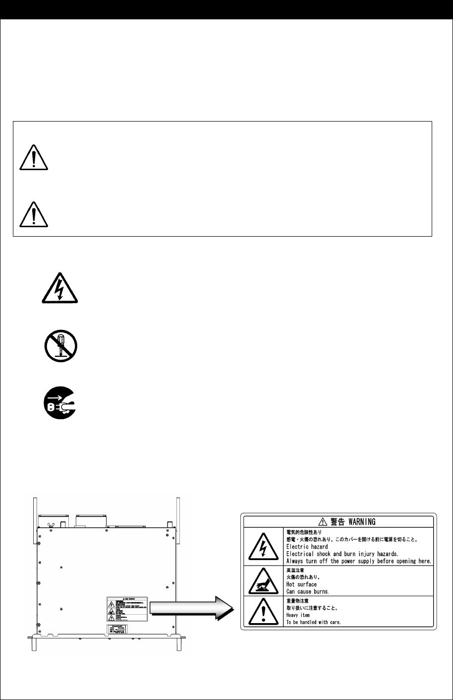
Concerning the WARNING labels
The WARNING labels are put on the NTD-2250/2500 Transceiver, NBD-2250/2500
Power supply, NFC-2250/2500 Antenna tuner, and NBB-714/724 Battery charger.
Do not take off, destroy, or modify the labels.
NTD-2250/2500 Transceiver (Upper view)
vii
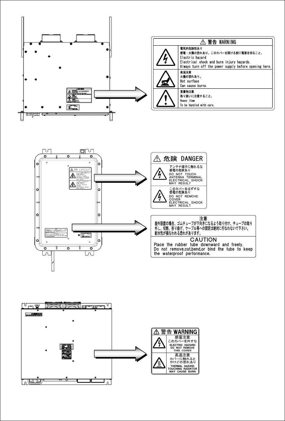
NBD-2250/2500 Power supply (Upper view)
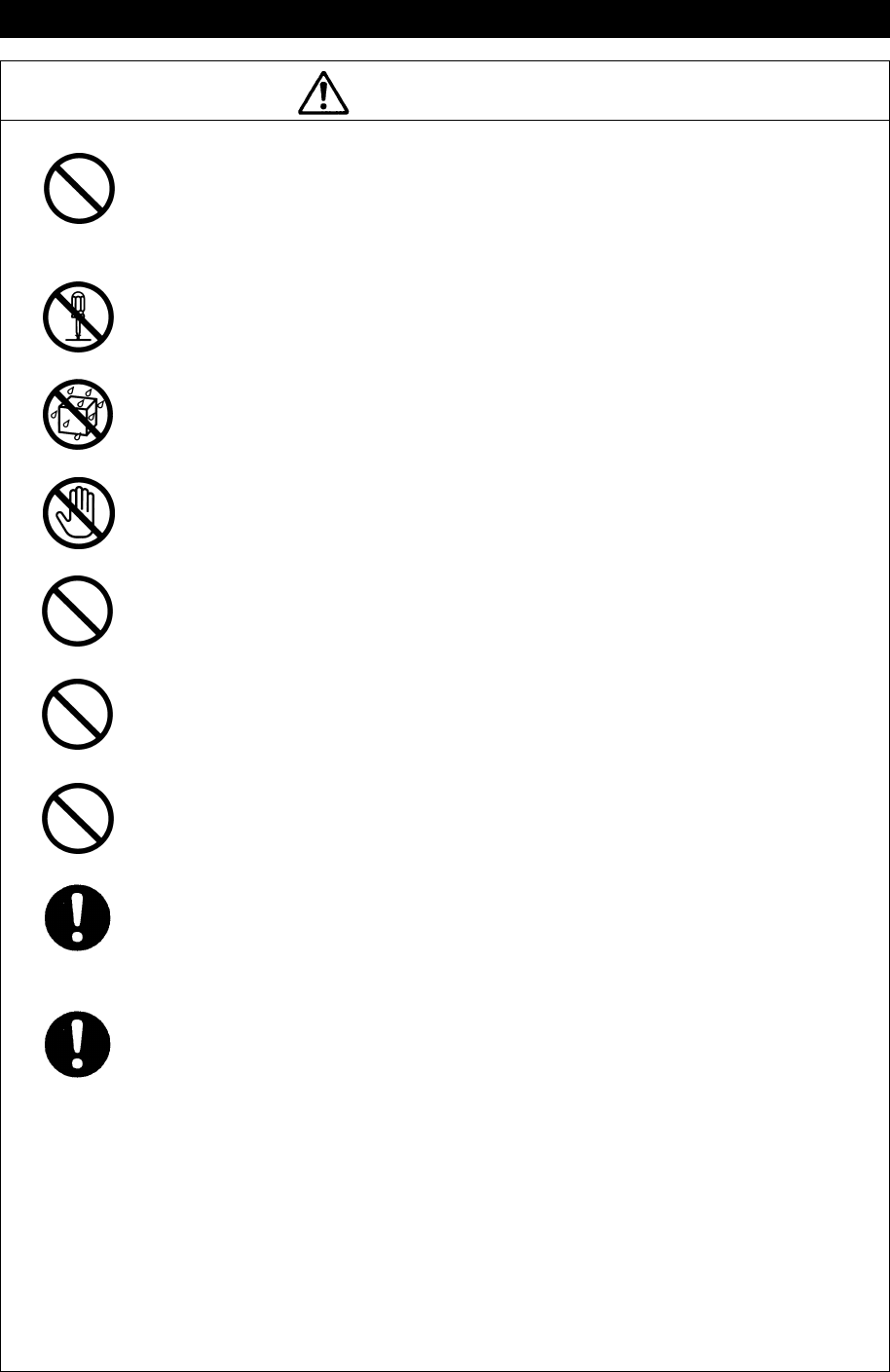
NFC-2250/2500 Antenna tuner
NBB-714/724 Battery charger
viii
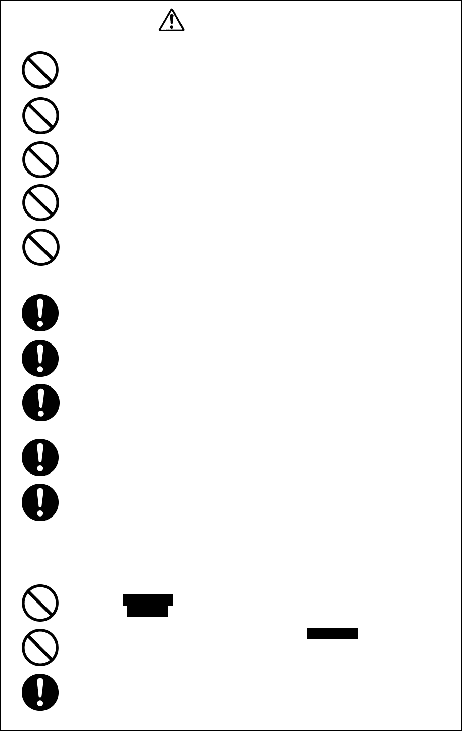
Handling precautions
WARNING
Do not open the equipment to inspect or repair internal circuits. Inspection or
repairs by anyone other than a specialized technician may result in fire, electrical
shock, or malfunction.
If internal inspection or repair is necessary, contact our service center or agents.
Do not disassemble or customize this unit.
Doing so may cause fire, electrical shock, or malfunction.
Do not get this equipment wet or spill any liquids on or near this equipment.
Doing so may cause electrical shock, or equipment malfunction.
Do not touch any of the areas with warning labels.
Doing so may cause electrical shock.
Do not use voltage other than that specified.
Doing so may cause fire, electrical shock, or malfunction.
Do not remove protective covers on the high voltage terminals.
Doing so may cause electrical shock.
Do not insert anything flammable into the equipment.
Doing so may cause fire, electrical shock, or malfunction.
If a distress alert is received, make sure to inform the ship's captain or officer in
charge.
Doing so may save the lives of the crews and passengers on the ship in distress.
This equipment is used for both distress communication and routine communication.
Contact JRC or our agent if any problem is observed in this unit during routine
operation or inspection.
ix
CAUTION
Do not use this equipment anyplace other than specified.
Doing so may cause failure or malfunction.
Do not turn the trimmer resistors or the trimmer capacitors on the PCB unit.
Doing so may cause failure or malfunction.
Do not install the equipment in a place near water or in one with excessive
humidity, steam, dust, or soot.
Doing so may cause fire, electrical shock, or malfunction.
Do not test the distress alert.
Doing so may inconvenience local shipping and rescue centers.
Do not turn off the equipment when at sea because the SOLAS Convention
requires keeping watch on distress and safety frequencies at all times. Always
listen to 2187.5 kHz, and 8414.5 kHz, and one or more of the following
frequencies; 4207.5 kHz, 6312.0 kHz, 12577.0 kHz, or 16804.5 kHz. In class B
mode, it is necessary to keep watch only on 2187.5 kHz.
When completely turning off the power to the equipment, turn off the breakers
on the power supply.
To operate DSC functions of the equipment, the ID numbers assigned to the ship
must be registered in advance. If registration is necessary, contact our service
center or agents.
To install this equipment, contact our service center or agents.
Special knowledge on selecting the place where the antenna is to be mounted
and setting the ID number (MMSI) assigned to the ship is required in addition to
installing the equipment.
When sending a distress alert, follow the instructions of the ship's captain or
officer in charge.
If a false distress alert is transmitted accidentally, select the Cancel menu and
transmit the distress cancel referring the guidance displayed on the controller. And
then report the false distress alert to a nearby RCC (Rescue Coordination Center/
in Japan, inform the nearest Japan Coast Guard.)
Information to be reported:
Ship's name, type, nationality, and ID number, the date/time, location and
reason why the false distress alert was transmitted. Also the unit model name
and manufacture number/date, if possible.
To turn off an alarm or clear a display such as a received DSC message, do not
press the DISTRESS key. Doing so may cause a false distress alert.
(Press the CANCEL key to turn off the alarm.)
When sending a drobose call, do NOT press the DISTRESS key. Doing so may
cause a false distress alert.
(Drobose calls can be sent via the [Call] button displayed on the screen.)
A distress acknowledgement or a distress relay call can be transmitted using the
option on an active procedure screen, but when sending such a call, follow the
instructions of the ship's captain or officer in charge.
x
CAUTION
DSC messages with incorrect format or data may not be received, but it is not a
malfunction. Also if the data terminal is not connected, the equipment does not
receive DSC calls requesting ARQ/FEC communication, regardless of either the
category of routine, safety, urgency or distress.
Received distress message logs are automatically deleted after 48 hours to avoid
accidental resending or other misoperation. Accordingly, if such messages cannot
be read, it is not a malfunction.
The received distress message logs are cleared when turning off the power by
such as the breaker on the power supply. Due to the SOLAS Convention
(keeping watch on distress and safety frequencies at all times), do not turn off the
equipment when at sea.
The time in the 7.1 Date & time menu means the present time, and is different
from the time in the 7.2 POS/TIME menu that means the time when the position
information is valid.
The time in the 7.2 POS/TIME menu means the time when the position
information is valid, and is different from the present time mentioned in the 7.1
Date & time menu.
When replacing fuses, always use fuses of the same type.
The batteries, except for sealed lead-acid batteries that require no equalization,
should be carried out the equalizing charge at least every six months
The thermal head of the NKG-91 printer may be very hot after printing. Do not
touch the thermal head of the printer. Make sure the thermal head is cool before
replacing the paper or cleaning the thermal head.
The paper used in the NKG-91 printer is heat sensitive. Take the following
precautions when using this paper.
・ Store the paper away from heat, humidity, or heat sources.
・ Do not rub the paper with any hard objects.
・ Do not place the paper near organic solvents.
・ Do not allow the paper to come in contact with polyvinyl chloride film,
erasers, or adhesive tape for long periods of time.
・ Keep the paper away from freshly copied diazo type or wet process copy
paper.
The print head of the NKG-800 printer may be very hot after printing. Do not
touch the print head of the printer. Make sure the print head is cool before
replacing the paper or cleaning the print head.
Do not use the NKG-800 printer if there is no ink ribbon cartridge or paper. Do not
twist the ink ribbon when installing the ink ribbon cartridge.
Before opening and closing the cover of the NKG-800 printer, turn off the printer.
Wait more than 2 seconds after turning the printer off before turning it back on
again so it can initialize correctly.
Be sure to unmount the USB flash memory before removing it from the NDZ-227
Data terminal at work.
xi
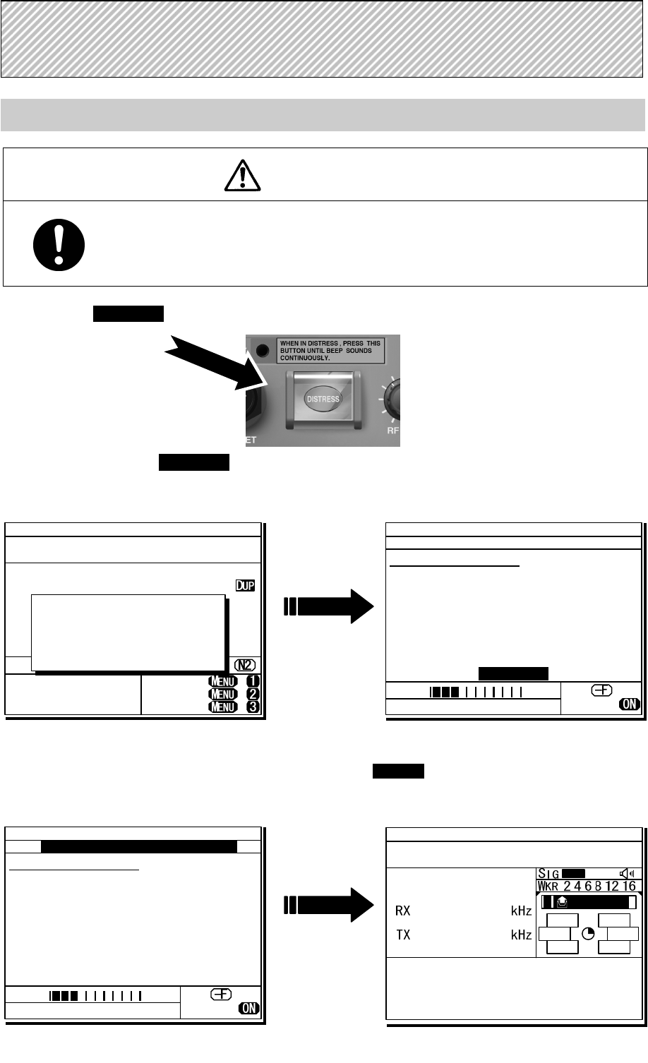
Sending a Distress Alert
CAUTION
When sending a distress alert, follow the instructions of the ship's captain or officer in
charge.
1
1
1.
.
.
Open the DISTRESS key cover on the NCM-2150 MF/HF CONTROLLER.
2
2
2.
.
.
Press and hold the DISTRESS key for 4 seconds to send the distress alert.
When the countdown is finished the screen below on the right is displayed, and after antenna
tuning the distress alerts are transmitted.
3
3
3.
.
.
After sending the distress alert, wait for an acknowledgement.
The radiotelephone can be used to communicate even while waiting for an acknowledgement on the screen
below left. When an acknowledgement is received, press the CANCEL key or ENT to cancel the alarm on the
below right screen, and communicate with the station. Unless an acknowledgement is received or the
distress alert is cancelled manually, the equipment repeats the distress alert every 3.5 to 4.5 minutes.
D
D
DI
I
IS
S
ST
T
TR
R
RE
E
ES
S
SS
S
S
A
A
AL
L
LE
E
ER
R
RT
T
TS
S
S
TEL ITU- 401
4357.0
4065.0
RX kHz
TX kHz
NonDST: +
DROBOS: +
EdtDST: +
ID 431001234 23:59(UTC)
Pos 89゚59.0123'N
179゚59.6789'E@23:59 (EXT)
SIG
WKR scan bands:
2 4 6 8 12 16MHz
Distress call starts
in sec
4
ID 431001234 23:59(UTC)
DSC Rx: 2187.5/Tx: 2187.5kHz
Distress calling
Next :---
Stage :Waiting for CH free
Call-F: / / / / /
Nature:Undesignated
PosUTC: 89゚59.0123'N
:179゚59.6789'E @23:59
Mode :Radiotelephone
[Cancel]
SIG
WKR 2 4 6 8 12 16MHz
ID 431001234 23:59(UTC)
TEL Rx: 8291.0/Tx: 8291.0kHz
Distress calling
Next :Resends 4.1min later
Stage :Waiting for ACK
Call-F:2/4/6/8/12/16
Nature:Undesignated
PosUTC: 89゚59.0123'N
:179゚59.6789'E @23:59
Mode :Radiotelephone
[FRQ][Pause][POS][CHNG][Cancel]
Rx: 8291.0/Tx: 8291.0kHz
SIG
WKR 2 4 6 8 12 16MHz
TEL
2182.0
2182.0
ID 431001234 23:59(UTC)
Pos 89゚59.0123'N
179゚59.6789'E@23:59 (EXT)
RxID:123456789|OWN D-ACK|2MHz
DIST acknowledged(00.2min)
Tx:2|4|6|8|12|16/Undesignated /TEL
89゚59.0123'N179゚59.6789'E@23:59
Press CANCEL to silence alarm.
A DST ALT
xii
4
4
4.
.
.
After receiving acknowledgement, use the radiotelephone to request rescue.
First, the responding station calls by radiotelephone. Communicate the following information to that station.
z Say "MAYDAY".
z Say "This is (name of your ship)".
z Tell the station the ship's Maritime Mobile Service Identity (MMSI) number, call sign, ship's position,
nature of distress, and rescue requests.
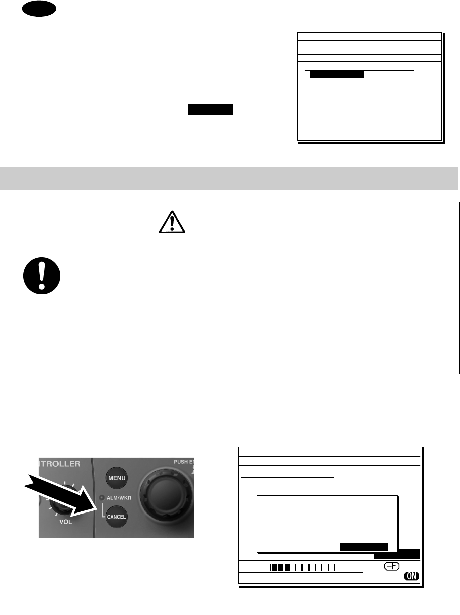
If time permits, enter the nature of the distress or the mode (Radiotelephone or FEC) as follows,
just before sending the distress alert. (For more details, see 4.5.5 Distress alerts.)
1) Open menu 3. Editing a distress msg.
2) Press ENT on the screen at right and select
the nature of the distress.
3) Press ENT to confirm the selection.
The nature of the distress is set. If the position
and time (UTC) are not displayed automatically
for any reason, input them manually at this time.
4) Press and hold the DISTRESS key for 4
seconds to send the distress alert.
The rest of the procedure is the same as
described above.
Terminating a Distress Alert
CAUTION
If a false distress alert is transmitted accidentally, select the Cancel menu and transmit
the distress cancel referring the guidance displayed on the controller. And then report
the false distress alert to a nearby RCC (Rescue Coordination Center/ in Japan, inform
the nearest Japan Coast Guard.)
Information to be reported:
Ship's name, type, nationality, and ID number, the date/time, location and reason why
the false distress alert was transmitted. Also the unit model name and manufacture
number/date, if possible.
Select the Cancel menu and press ENT on the NCM-2150 MF/HF CONTROLLER.
The screen shown below is displayed. Then select Continue with the jog dial and press ENT to start the
distress cancel procedure referring the guidance displayed on the controller.
Note) For more details, see the description in the 4.5.5.1 Quick distress alerts.
Note
ID 431001234 23:59(UTC)
Pos 89゚59.0123'N
179゚59.6789'E@23:59 (EXT)
TEL Rx: 4146.0/Tx: 4146.0kHz
3)Editing a distress msg
Nature :[Undesignated ]
Position :[NE]
[ 89゚59.0123'N]
[179゚59.6789'E]
UTC of pos :[23:59]
Mode :[Radiotelephone]
Attempt type:[Multi-FRQ ]
Tx bands :[2/4/6/8/12/16]
[Preview] [Tips] [Cancel]
Nature
ID 431001234 23:59(UTC)
TEL Rx: 2182.0/Tx: 2182.0kHz
Distress calling
Next :Resends 3.2min later
Stage :Waiting for ACK
Call-F:2/4/6/8/12/16
Nature:Undesignated
PosUTC: 89゚59.0123'N
:179゚59.6789'E @23:59
Mode :Radiotelephone
[FRQ][Pause][POS][CHNG][Cancel]
[Cancel]
!!Warning!!
Cancel the transmitted
false distress alert?
(TGT: 2/4/6/8/12/16M)
[Continue] [Return]
[Return]
SIG
WKR 2 4 6 8 12 16MHz
xiii
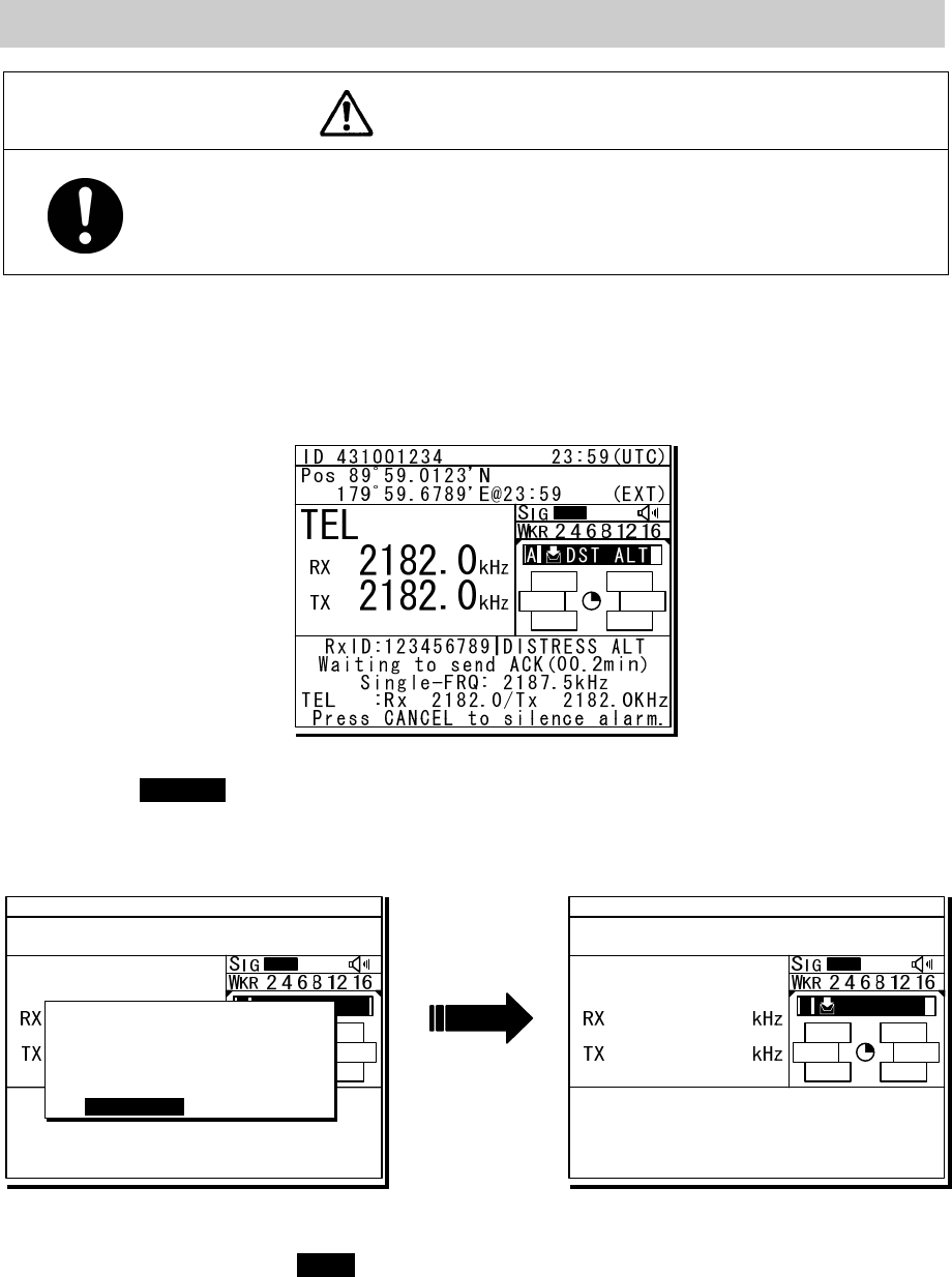
Receiving a Distress Alert
WARNING
If a distress alert is received, make sure to inform the ship's captain or officer in charge.
Doing so may save the lives of the crew and passengers on the ship in distress.
1
1
1.
.
.
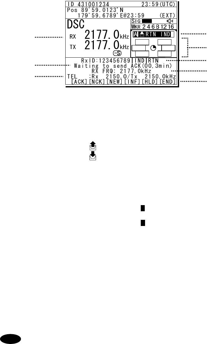
When a distress alert is received, the information such as the ID number of the ship in
distress and the stage of the distress event are displayed.
If the equipment is not used, i.e. there is no active procedure at that time, a distress and safety frequency is
set and the ALM lamp starts blinking, and an alarm gradually grows louder.
2
2
2.
.
.
Press the CANCEL key to stop the alarm. If the popup screen is shown, select "Accept"
and press ENT.
After the specified communicate mode and the distress frequency are set, keep watch under such a condition.
Keep watch for five minutes or more, and executes the report to the coast station etc. as appropriate
3
3
3.
.
.
To acknowledge to the distress alert after coordination with the coast station, from the
above right screen, press FUNC key to move the active screen to the message control area.
Then select ACK with jog dial and press ENT to send the acknowledgement.
After acknowledging the distress alert, communicate with the ship in distress as follows;
z Say "MAYDAY".
z Repeat the identity (MMSI) of the ship in distress 3 times
z Say, "This is".
z Repeat the identity (MMSI) of your ship 3 times
z Say "RECEIVED MAYDAY".
TEL
8291.0
8291.0
ID 431001234 23:59(UTC)
Pos 89゚59.0123'N
179゚59.6789'E@23:59 (EXT)
RxID:123456789|DISTRESS ALT
Waiting to send ACK(00.6min)
Multi-FRQ:2/ / /8/ /16
TEL :Rx 8291.0/Tx 8291.0KHz
[ACK][RLY][INF][FRQ][HLD][END]
A DST ALT
TEL
2182.0
2182.0
ID 431001234 23:59(UTC)
Pos 89゚59.0123'N
179゚59.6789'E@23:59 (EXT)
A R:DST ALTA R:DST ALT
RxFR:123456789|DISTRESS ALT
Waiting to send ACK(00.2min)
Single-FRQ: 2187.5kHz
TEL :Rx 2182.0/Tx 2182.0kHz
[ACK][RLY][INF][FRQ][HLD][END]
SAME DST ON ANOTHER FRQ
From :123456789
Work-F : 8291.0kHz
EQP will tune to the
above FRQ within 10s.
[Accept] [Ignore]
[Accept]
xiv
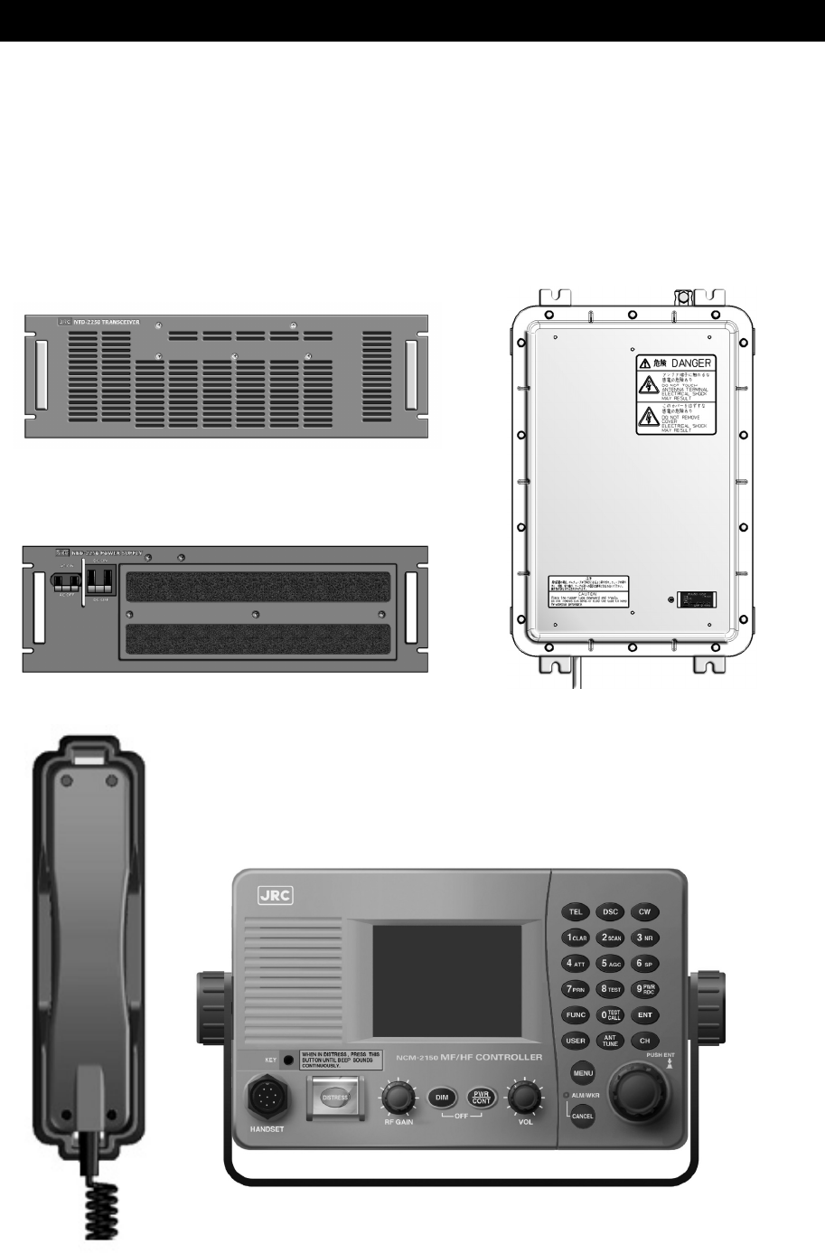
Equipment exterior
● JSS-2250/2500 (JSS-2250N/2500N) 250W/500W MF/HF Radio Equipment
Note: According to the composition, the model variants are as follows.
- JSS-2250 :250W Radiotelephone/ DSC
- JSS-2250N :250W Radiotelephone/ DSC & NBDP
- JSS-2500 :500W Radiotelephone/ DSC
- JSS-2500N :500W Radiotelephone/ DSC & NBDP
In this document, unless otherwise specified, “JSS-2250/2500” may include “JSS-2250N/2500N”.
NTD-2250/2500 Transceiver
NBD-2250/2500 Power supply NFC-2250/2500 Antenna tuner
NCM-2150 MF/HF Controller/NQW-261 Handset
xv
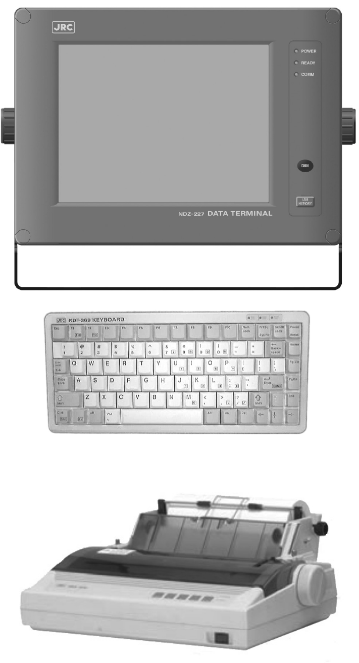
NDZ-227 Data terminal / NDF-369 Keyboard
NKG-800 Printer
xvi
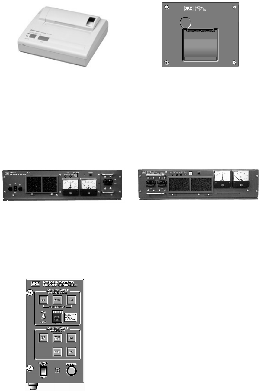
● DPU-414 Printer
● NKG-91 Printer
● NBB-714 Battery charger (10A)
● NBB-724 Battery charger
● NCH-321A Distress Message Controller (DMC)

Contents
Preface ......................................................................................................... v
Before operation ......................................................................................... vi
Handling precautions ................................................................................. viii
DISTRESS ALERTS .................................................................................... xi
Equipment exterior ..................................................................................... xiv
Glossary of terms ....................................................................................... xxi
1. EQUIPMENT OVERVIEW ........................................................................ 1-1
1.1 Functions ................................................................................................................... 1-1
1.2 Features ..................................................................................................................... 1-1
1.3 Basic configuration .................................................................................................... 1-2
1.3.1 DSC model (JSS-2250/2500) ................................................................................ 1-2
1.3.1.1 Standard components .................................................................................. 1-2
1.3.1.2 Options ........................................................................................................... 1-2
1.3.2 DSC/NBDP model (JSS-2250N/2500N) ................................................................ 1-3
1.3.2.1 Standard components .................................................................................. 1-3
1.3.2.2 Options ........................................................................................................... 1-3
1.3.3 System configuration ........................................................................................... 1-4
1.4 External dimensions .................................................................................................. 1-5
1.5 Block diagram ............................................................................................................ 1-12
1.5.1 DSC model (JSS-2250/2500) ................................................................................ 1-12
1.5.2 DSC/NBDP model (JSS-2250N/2500N) ................................................................ 1-13
2. NAMES AND FUNCTIONS ...................................................................... 2-1
2.1 Controller (NCM-2150) .............................................................................................. 2-1
2.2 Controller’s display ...................................................................................................... 2-3
2.2.1 Status display ....................................................................................................... 2-3
2.2.2 Operating display ................................................................................................. 2-4
2.2.3 Function screen and key operations .................................................................... 2-6
2.2.4 Menu screen ........................................................................................................ 2-7
2.3 Data terminal(NDZ-227) ......................................................................................... 2-8
2.4 Display of data terminal ............................................................................................... 2-9
2.4.1 Regular screen ..................................................................................................... 2-9
2.4.2 Telex communication screen ................................................................................ 2-10
2.4.3 Message file edit screen ...................................................................................... 2-11
3. INSTALLATION ........................................................................................ 3-1
4. OPERATION ............................................................................................ 4-1
4.1 Operation overview ................................................................................................... 4-1
4.1.1 Operation of the controller .................................................................................... 4-1
4.1.2 Operation of the data terminal ............................................................................. 4-4
4.2 Basic communications procedure ............................................................................. 4-6
4.2.1 Turning on the power .......................................................................................... 4-6
4.2.2 Turning off the power/ Putting into sleep mode ................................................... 4-7
4.2.3 Communicating in radiotelephone mode ............................................................ 4-8
4.2.4 Communicating in CW mode .............................................................................. 4-10
4.2.5 Receiving AM broadcasts .................................................................................... 4-12
4.2.6 Communicating in telex mode (TLX) ................................................................... 4-13
4.2.6.1 ARQ mode operation ................................................................................... 4-13
4.2.6.2 CFEC mode operation ................................................................................. 4-16
4.2.6.3 SFEC mode operation ................................................................................. 4-20
4.2.6.4 Editing telex messages ................................................................................ 4-22
4.3 Setting the radio ........................................................................................................ 4-25
4.3.1 Setting the communication frequencies .............................................................. 4-25
4.3.2 Setting the communication channels .................................................................. 4-26
4.3.3 Setting the automatic gain control (AGC) ........................................................... 4-30
4.3.4 Setting the noise reduction (NR) ......................................................................... 4-30
4.3.5 Setting the attenuation (ATT) .............................................................................. 4-31
4.3.6 Setting the clarifier ............................................................................................... 4-31
4.3.7 Setting the squelch level ..................................................................................... 4-32
4.3.8 Setting the CW bandwidth ................................................................................... 4-32
4.3.9 Scanning the Rx frequencies .............................................................................. 4-33
4.3.10 Reducing the Tx power ....................................................................................... 4-35
4.3.11 Setting the antenna tuning power ....................................................................... 4-35
4.3.12 Setting the Auto Tune Start (ATS) function .......................................................... 4-35
4.4 Basic DSC operations ................................................................................................. 4-36
4.4.1 Routine calls to an individual station ................................................................... 4-36
4.4.2 Receiving routine individual calls ........................................................................ 4-38
4.4.3 Routine group calls .............................................................................................. 4-40
4.4.4 Receiving routine group calls .............................................................................. 4-40
4.5 Emergency calls (DSC distress/urgency/safety calls) ................................................ 4-41
4.5.1 Safety or urgency calls to an individual station ................................................... 4-41
4.5.1.1 Special safety individual calls ...................................................................... 4-41
4.5.2 Receiving safety or urgency individual calls ....................................................... 4-43
4.5.2.1 Receiving special safety individual calls ...................................................... 4-43
4.5.3 Safety or urgency area calls ................................................................................ 4-44
4.5.4 Receiving safety or urgency area calls ............................................................... 4-45
4.5.5 Distress alerts ...................................................................................................... 4-46
4.5.5.1 Quick distress alerts .................................................................................... 4-46
4.5.5.2 Distress alerts from the menu ...................................................................... 4-49
4.5.5.3 Receiving distress alerts .............................................................................. 4-52
4.5.6 Distress relay calls on behalf of someone else (DROBOSE) ............................. 4-53
4.6 DSC call log ............................................................................................................... 4-55
4.6.1 Received distress messages ............................................................................... 4-55
4.6.2 Received other messages ................................................................................... 4-56
4.6.3 Transmitted messages ......................................................................................... 4-56
4.7 Display of telex communication logs ......................................................................... 4-57
4.8 USB memory operation ............................................................................................. 4-58
4.9 Popup screens ........................................................................................................... 4-59
5. SETTINGS & REGISTRATIONS .............................................................. 5-1
5.1 Date and time settings ............................................................................................... 5-1
5.2 Own ship position and time settings .......................................................................... 5-3
5.3 Controller settings ...................................................................................................... 5-4
5.3.1 LCD adjustment ................................................................................................... 5-4
5.3.2 Sound settings ..................................................................................................... 5-4
5.3.3 User key assignments .......................................................................................... 5-5
5.3.4 Selecting Tx meters ............................................................................................. 5-6
5.3.5 Transferring user channel data to another controller ........................................... 5-7
5.3.6 Setting the inactivity timer (for menu shutdown) .................................................. 5-8
5.3.7 Setting the reference value for the channel auto search ..................................... 5-8
5.4 Registering user channels ......................................................................................... 5-9
5.5 Advanced settings for DSC/WKR .............................................................................. 5-11
5.5.1 Automatic acknowledgement ............................................................................... 5-11
5.5.2 Setting DSC watch frequency .............................................................................. 5-11
5.5.3 Setting receiving alarms ....................................................................................... 5-12
5.5.4 Using medical/neutral settings for urgency calls .................................................. 5-12
5.5.5 Registering the ship's group ID ............................................................................ 5-12
5.5.6 Setting the inactivity timer (for procedures on hold) ............................................ 5-13
5.5.7 Registering the DSC call list ................................................................................ 5-13
5.6 Setting connections for options ................................................................................. 5-14
5.7 Setting of data terminal .............................................................................................. 5-15
5.7.1 LCD adjustment ................................................................................................... 5-15
5.7.2 Registering station list .......................................................................................... 5-17
5.8 Setting telex mode ..................................................................................................... 5-19
6. MAINTENANCE & INSPECTION ............................................................. 6-1
6.1 General maintenance & inspection ............................................................................ 6-1
6.2 Self diagnosis inspection ........................................................................................... 6-2
6.3 System alarm indication ............................................................................................ 6-5
6.3.1 Alarm list .............................................................................................................. 6-6
6.3.2 Viewing the alarm history ..................................................................................... 6-9
6.4 Software version ........................................................................................................ 6-10
6.5 Troubleshooting ......................................................................................................... 6-11
6.5.1 Procedures for locating malfunctions ................................................................... 6-11
6.5.2 Guide to locating faults ........................................................................................ 6-12
6.5.3 Consumables ....................................................................................................... 6-13
6.5.4 Repair units/parts ................................................................................................. 6-13
6.5.5 Regular replacement parts ................................................................................... 6-14
7. AFTER-SALES SERVICE ....................................................................... 7-1
8. DISPOSAL ............................................................................................... 8-1
9. SPECIFICATIONS ................................................................................... 9-1
9.1 JSS-2250/2500 MF/HF Radio Equipment ................................................................ 9-1
9.2 Options ...................................................................................................................... 9-5
9.3 Peripheral interfaces ................................................................................................. 9-7
10. OPTIONS OPERATION ......................................................................... 10-1
10.1 Battery charger (NBB-714) ....................................................................................... 10-1
10.2 Battery charger (NBB-724) ....................................................................................... 10-3
10.3 Printer (NKG-91) ....................................................................................................... 10-5
10.4 Printer (NKG-800) ..................................................................................................... 10-6
10.5 Operations using a SELCALL unit ............................................................................ 10-9
11. Appendix ............................................................................................... 11-1
11.1 Frequencies for distress and safety calls .................................................................. 11-1
11.2 National DSC frequencies for routine calls ............................................................... 11-2
11.3 International DSC frequencies for routine calls ........................................................ 11-2
11.4 ITU channel list (TEL/CW/TLX) ................................................................................ 11-3
11.5 Guide to MF/HF operation ........................................................................................ 11-23
Declaration on toxic & hazardous substances or elements
Marking with market circulation mark

xxi
Glossary of terms
This section defines general and DSC terms related to this equipment.
● General terms
AMVER
Automated Mutual-assistance Vessel
Rescue System
System that informs another ship of position
of distress ship operated in the United States.
ARQ
Automatic Repeat reQuest
When communicating interactive in the telex
mode, this ARQ is used.
CFEC
Collective Forward Error Correction
When broadcasting in the telex mode, this
CFEC is used.
DSC
Digital Selective Calling device
Used in routine calls, safety and urgency
calls, and distress alerts for rescue requests.
GMDSS
Global Maritime Distress and Safety System.
GPS
Global Positioning system
IMO
International Maritime Organization
ITU
International Telecommunication Union
Establishes conventions and regulations for
all electrical wired and radio, land, sea, air,
and space communications. It contains
internal organizations such as ITU-R and
ITU-T.
ITU-R
The International Telecommunications Union
(ITU) radio communications department.
JASREP
Japanese Ship Reporting System
Ship position reporting system operated in
Japan.
LT
Local time
MF/HF
Medium frequencies and high frequencies
(300 kHz to 30 MHz)
MMSI
Maritime Mobile Service Identity
The 9-digit Maritime Mobile Service Identity
number assigned to each ship and coast
station.
NBDP
Narrow Band Direct Printing
It is a generic name of the device used to
communicate in the telex mode.
NMEA
Maritime equipment transmission standard
established by the National Marine
Electronics Association.
PTT
Push to talk
RCC
Rescue Co-ordinate Center
RMS
Remote Maintenance System
Transmits ship equipment information
temporarily stored in the VDR via Inmarsat to
land, for use in maintenance and
management of radio equipment.
RR
Radio Regulations
International regulations for radio transmission
established by the treaty of the ITU.
SELCAL Number(Selective Calling Number)
Selective Calling Number by NBDP.
It is the numbers of four digits (coast station)
or five digits (Ship station) used when the
other party is specified in the telex mode.

xxii
SFEC
Selective Forward Error Correction
When broadcasting to a specific group in the
telex mode, this SFEC is used.
SOLAS Convention
International Convention for Safety of Life at
Sea
The international convention applies to all
ships engaged on international voyages. A
safety certificate is issued if the conditions of
this convention are satisfied.
SQL
Squelch
A function that acts to suppress the audio
output of a receiver in the absence of a radio
signal of sufficient strength.
UTC
Universal Time Coordinated
VOL (Volume)
Speaker volume
WRC
World Radiocommunication Conference
WKR
Watch Keeping Receiver
The WKR is the receiver dedicated to
monitoring the distress and safety
frequencies.
● DSC terms
Address
General term for Maritime Mobile Serive
Identity number (MMSI).
This equipment uses To/From to distinguish
between the sender and receiver. It also
means the Self-ID (own ship MMSI) and
Dist-ID (MMSI of a ship in distress).
Category
Message code indicating priority of the call.
Priority levels are listed below.
・ Routine… General calls for routine work
・ Safety…
Calls for safety communications
・ Urgency…
Calls for urgent communications
・ Distress…
Calls for distress communications
DROBOSE
Distress relay call (to individual or to area)
on behalf of someone else who is in distress.
EOS (End Of Sequence)
Termination code appended to call
messages.
Other codes are listed below.
・ ACK RQ… Acknowledgement request
・ ACK BQ… Acknowledgement responding
to the ACK RQ
ECC (Error Check Character)
Error check code appended to the end of call
messages.
This is not normally displayed, but if an error
occurs on a message, an ECC error is
displayed.
Mode
Message code indicating communication
mode after a DSC call.
This equipment is fixed to radiotelephone.
Radiotelephone (TEL) or ARQ and FEC
(TLX) can be used.
Nature of Distress
Message code indicating the type of distress
when a distress alert is issued.
Codes are listed below.
・ Fire… Fire, explosion
・ Flooding… Flooding
・ Collision… Collision
・ Grounding… Grounding
・ Listing… Risk of ship capsizing
・ Sinking… Sinking
・ Disabled… Ship inoperable/adrift
・ Undesignated… Undesignated distress
・ Abandoning… Abandoning ship
・ Piracy attack… Piracy/robbery attack
・ Man overboard… Man overboard
Polling
Polling is a feature for routine calling.
It is used, for example, to confirm whether a
ship is within radio range when a coast
station requests navigational information of
the ship.
Reason
Message code indicating reason for negative
acknowledgement response.
Codes are listed below.

xxiii
・ No reason… No reason
・ Congestion… Maritime information
exchange center
congested
・ Busy… Busy
・ Queue… Queued
・ Barred… Station barred
・ No operator… No operator
・ Temp no oper…
Temporarily no operator
・ EQP disabled… Equipment disabled
・ Unable FRQ… Indicated frequency
cannot be used
・ Unable mode…
Indicated mode cannot
be used
Rx FRQ
Received frequency of the call
Subject/ Sub
Message code clarifying communication
contents when sending an urgency call to all
ships.
When sailing in dangerous waters, such as
in areas of political instability, these call
messages are used with the following
information.
・ Neutral ship: In accordance with ITU
resolution 18 (Mob-83), inform all ships
that own ship is of neutral nationality.
・ Medical TRANSP: Inform all ships
that own ship is performing medical
transportation, and is protected under the
1949 Geneva Convention.
Topic
Message codes in an acknowledged message
After sending an individual call, "Unable to
comply" is displayed when the responding
station cannot comply.
Type
Message code indicating the type of the call.
Codes are listed below.
・ Individual call… Individual call message
・ Individual ACK… Acknowledgement of
individual call message
・
Individual NACK
…
Negative acknowledgement
of individual call message
・ Group call… Group call message
・ GEO area call… Area call message
・ All ships call… Call to all ships
・ Distress… Distress alert message
・ Distress ACK… Acknowledgement of
distress alert message
・ Distress relay… Distress relay message
・
Distress relay ACK
… Acknowledgement of
distress relay message
・
Distress relay GEO
… Area call of distress
relay message
Intent
Message code indicating specific content.
Indicates the type of the call for a specific
purpose, not for radiotelephone
communication.
・ Polling… Polling
・ Position RQ… Ship position request
・ Ship position…
Ship position notification
・ Test… Safety test call
Work FRQ/ WFRQ
Message code indicating communication
frequency after a DSC call.
xxiv

Equipment Overview
1-1
1. EQUIPMENT OVERVIEW
1.1 Functions
This equipment includes MF/HF transceiver, Class-A DSC and DSC watch keeping receiver required
as the Global Maritime Distress and Safety System (GMDSS). It is designed as a separated
transceiver and small, lightweight controller(s) for easy installation not only in SOLAS Convention
ships such as international passenger ships and freight ships of 300 tons or more, but also
non-conventional ships of less than 300 tons.
As for the main communication function, in addition to the communications of radiotelephone with the
handset and the Morse communication with the CW keyer, calling by digital selective calling (DSC) for
a general or distress communication are possible. Furthermore, if the data terminal is connected to the
controller, the telex communication in the ARQ or FEC mode using the NBDP is available.
1.2 Features
● Compliant with the ITU Radio Regulations (RR), the IMO performance standards, and the ITU-R
recommendations.
● Contains all channels specified in the ITU Radio Regulations (RR).
● The separately designed controller and main unit enable easy installation in limited or difficult
spaces.
● A semi-transmissive LCD with a wide viewing angle is easily viewable even in direct light or when
backlit and allows it to be installed in a variety of positions.
● The backlights of the LCD and operation keys are fully adjustable, preventing interference with
night watch keeping.
● When in distress, the DSC can send a distress message with the expanded position data accurate
up to 1/10000 of a minute for both latitude and longitude to make search and rescue operations by
the RCC easier.
● High-quality stable operation is possible by using DSP technology on a transceiver with a
DSC/WKR modem.
● The DSC operates in Class A mode suitable for all areas, and in Class B mode limited to ships
navigating in A1 and A2 areas.
● An advanced digital audio amplifier with a built-in loud speaker provides a maximum of 5 W of
clear audio.
● The maintenance and the check can be easily done at daily or the regular services, because a
special function key was prepared for the DSC safety test calling and the self-diagnosis.
● It is possible to operate on the screen with the character color and the background color
corresponding to the favor because the data terminal for the telex communication by NBDP
adopted the color liquid crystal display of the wide viewing angle in high brightness.
● Besides printers and GPS, other peripherals such as the remote maintenance system (RMS) can
be connected to the equipment.

Equipment Overview
1-2
1.3 Basic configuration
1.3.1 DSC model (JSS-2250/2500)
1
1.
.3
3.
.1
1.
.1
1
Standard components
No. Description Model Qty Notes
1 Transceiver NTD-2250/2500 1 For 250W and 500W respectively
2 Power supply NBD-2250/2500 1 For 250W and 500W respectively
3 MF/HF controller NCM-2150 1
3-1 Controller cable 7ZCJD0343 1 5m
3-2 Handset NQW-261 1 Includes the cradle
4 Antenna tuner NFC-2250/2500 1 For 250W and 500W respectively
5 Instruction manual 7ZPJD0622 1 This manual
1
1.
.3
3.
.1
1.
.2
2
Options
No. Description Model Notes
1 Battery charger NBB-724 22A
2 Battery charger NBB-714 10A *For maintenance-free sealed battery only
3 Joint box JQD-69C For both RX and WKR
4 Junction box NQD-2253
5 Coaxial connector M-P-7, M-A-JJ For RG-12/UY and RG-10/UY
6 MF/HF controller NCM-2150 One additional controller available.
6-1 Controller cable 7ZCJD0343 5m
6-2 Handset NQW-261 Waterproof type (IP66 equivalent)
6-3 Flush mounting bracket MPBC42957
6-4 Mounting bracket MPBX44354
6-5 Connection box NQD-2250
For extension and expansion of the controller
7 Printer NKG-800/900
Desktop type
7-1 Printer connection cable 6ZCSC00407
7-2 Printer power cable 6JNKD00100B
7-3 Printer paper 5ZPCM00020
7-4 Ink ribbon (SP-16051) 5ZZCM00003
8 Printer NKG-91
Wall mount or
flush mount type
8-1 Printer connection cable 7ZCJD0254A
8-2 Printer paper 7ZPJD0384
8-3 Wall mounting bracket MPBP31446
9 Printer DPU-414
Desktop type
9-1 Printer connection cable 7ZCJD0254A
9-2 Printer power cable 7ZCJD0257C
9-3 Printer paper 6ZCAF00252A
10
Distress message controller
NCH-321A

Equipment Overview
1-3
1.3.2 DSC/NBDP model (JSS-2250N/2500N)
1
1.
.3
3.
.2
2.
.1
1
Standard components
No. Description Model Qty Notes
1 Transceiver NTD-2250/2500 1 For 250W and 500W respectively
2 Power supply NBD-2250/2500 1 For 250W and 500W respectively
3 MF/HF controller NCM-2150 1
3-1 Controller cable 7ZCJD0343 1 5m
3-2 Handset NQW-261 1 Includes the cradle
4 Antenna tuner NFC-2250/2500 1 For 250W and 500W respectively
5 Data terminal NDZ-227 1
NBDP option
5-1 DTE cable 7ZCJD0388 1
5-2 DTE power cable 7ZCJD0419 1
5-3 Keyboard NDF-369 1
6 Printer NKG-800 1
6-1 Printer connection cable 7ZCSC0205A 1
6-2 Printer power cable 6JNKD00100B 1
7 Instruction manual 7ZPJD0622 1 This manual
1
1.
.3
3.
.2
2.
.2
2
Options
No. Description Model Notes
1 Battery charger NBB-724 22A
2 Battery charger NBB-714 10A *For maintenance-free sealed battery only
3 Joint box JQD-69C For both RX and WKR
4 Junction box NQD-2253
5 Coaxial connector M-P-7, M-A-JJ For RG-12/UY and RG-10/UY
6 MF/HF controller NCM-2150 One additional controller available.
6-1 Controller cable 7ZCJD0343 5m
6-2 Handset NQW-261 Waterproof type (IP66 equivalent)
6-3 Flush mounting bracket MPBC42957
6-4 Mounting bracket MPBX44354
6-5 Connection box NQD-2250
For extension and expansion of the controller
7 Data terminal NDZ-227
For expansion of the controller
7-1 DTE cable 7ZCJD0388
7-2 DTE power cable 7ZCJD0419
7-3 Keyboard NDF-369
7-4 Mounting bracket MPBP31721
7-5 USB memory UDG4-1GAR-JRC Hagiwara Sys-Com / 1GB
8 Printer NKG-800/900
Desktop type
8-1 Printer connection cable 7ZCSC0205A
8-2 Printer power cable 6JNKD00100B
8-3 Printer paper 5ZPCM00020
8-4 Ink ribbon (SP-16051) 5ZZCM00003
9 Printer NKG-91
Wall mount or
flush mount type
9-1 Printer connection cable 7ZCJD0254A
9-2 Printer paper 7ZPJD0384
9-3 Wall mounting bracket MPBP31446
10 Printer DPU-414
Desktop type
10-1 Printer connection cable 7ZCJD0254A
10-2 Printer power cable 7ZCJD0257C
10-3 Printer paper 6ZCAF00252A
11
Distress message controller
NCH-321A
Equipment Overview
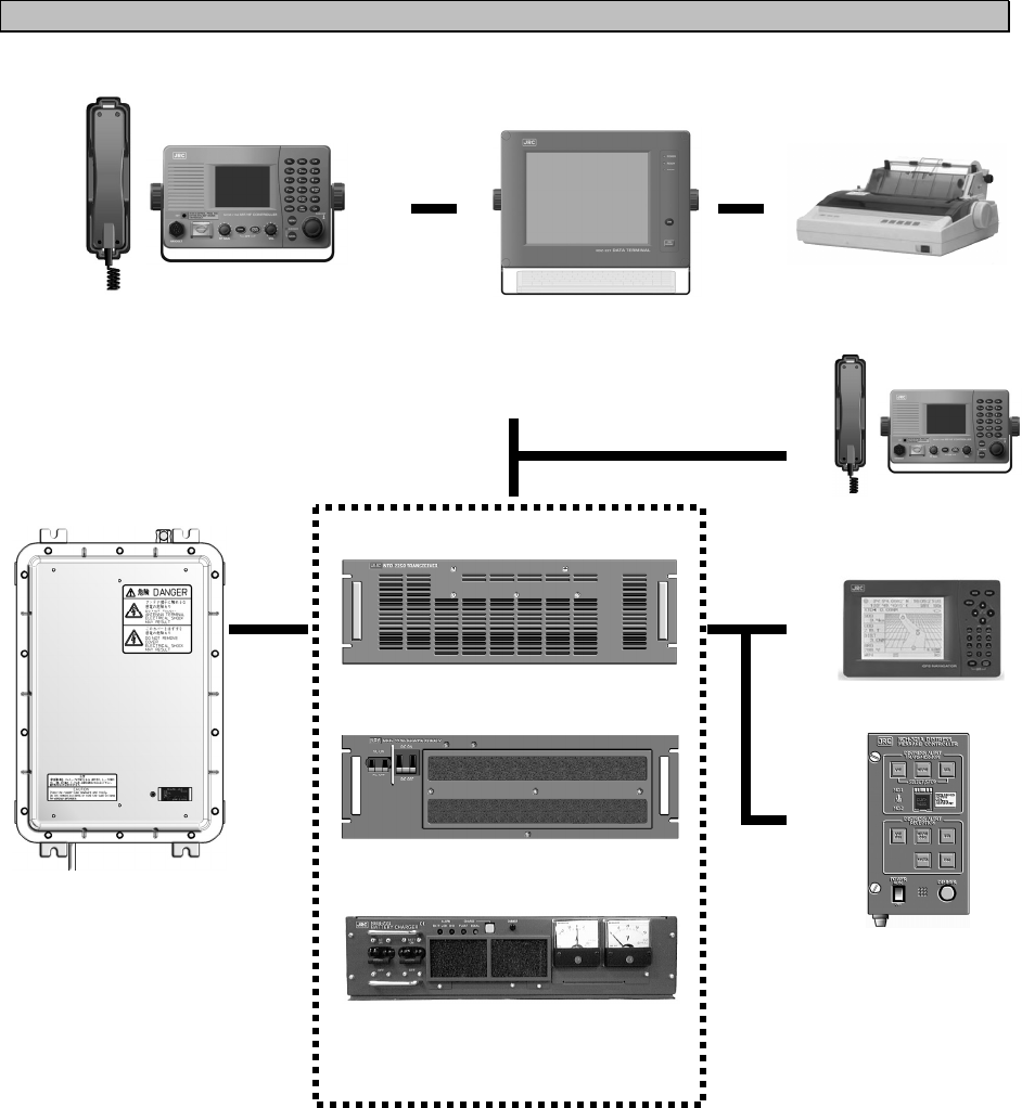
1-4
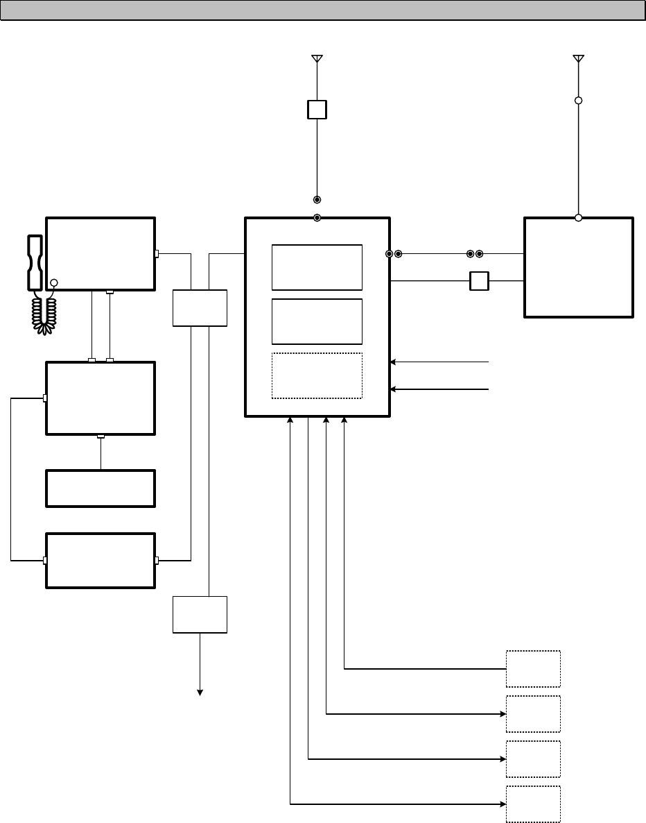
1.3.3 System configuration
NCH-321A DMC
GPS
NTD-2250/2500 Transceiver
Expansion Controller
* The equipment can also be
connected to the VDR
server to use the remote
maintenance system.
NFC-2250/2500
Antenna Tuner
NCM-2150 MF/HF Controller
NQW-261 Handset
NKG-800 Printer
NDZ-227 Data terminal
NDF-369 Keyboard
(DSC/NBDP model only)
NBD-2250/2500 Power supply
NBB-724 Battery charger
Equipment Overview
1-5
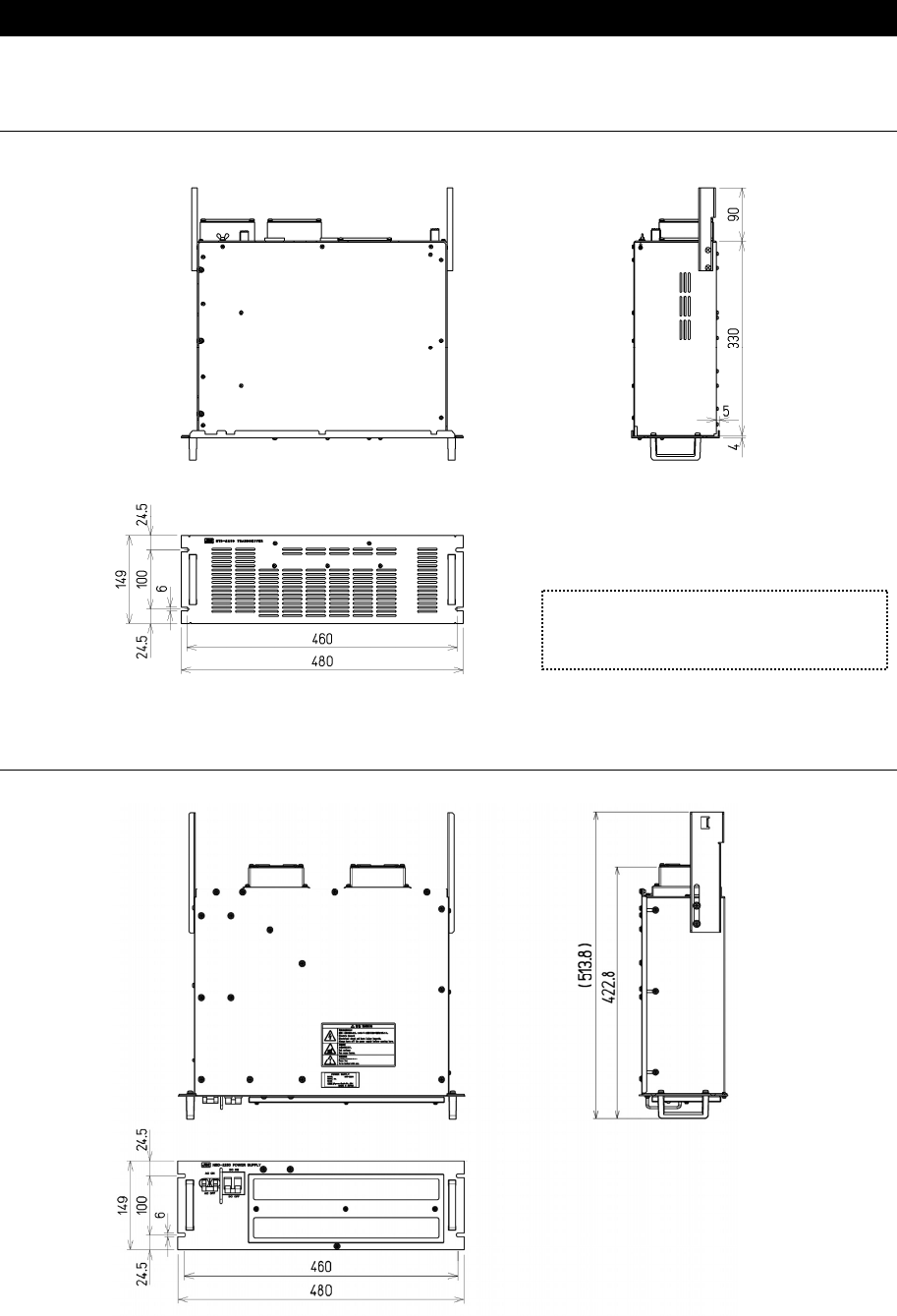
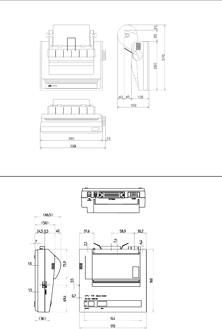
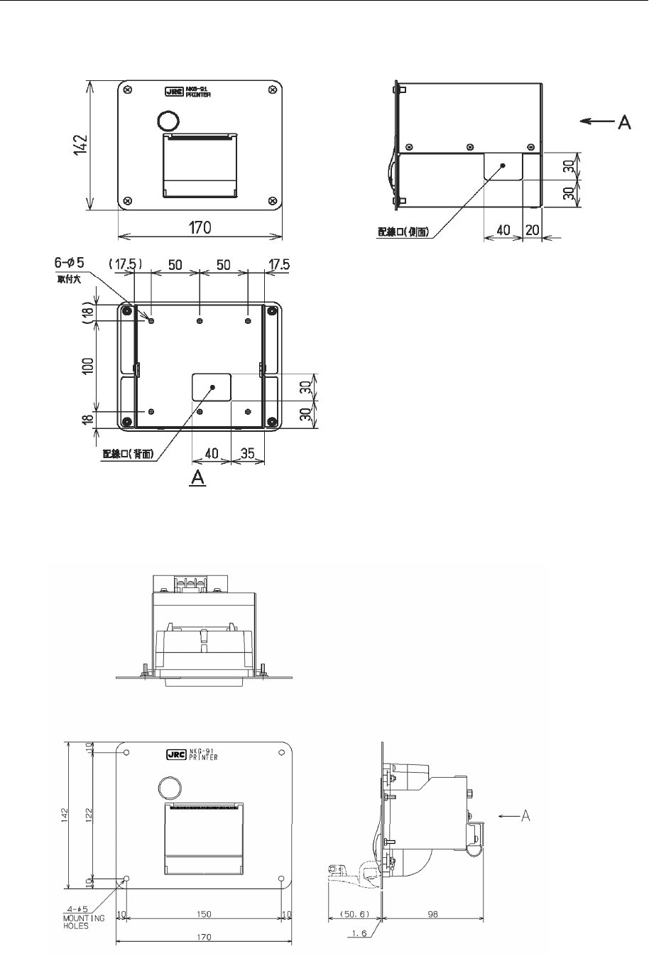
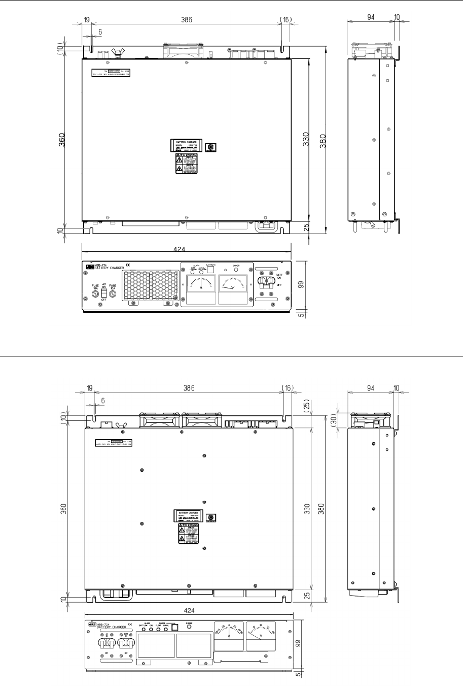
1.4 External dimensions
Below are the external dimensions of each unit.
(1) Transceiver (NTD-2250/2500)
(2) Power Supply (NBD-2250/2500)
Unit: mm
Weight: Approx. 15 kg/ 17 kg
Unit: mm
Weight: Approx. 15 kg/ 18 kg
Note) This figure shows the NTD-2250.
Incase of the NTD-2500, 3 fans are
mounted on the back.
Equipment Overview
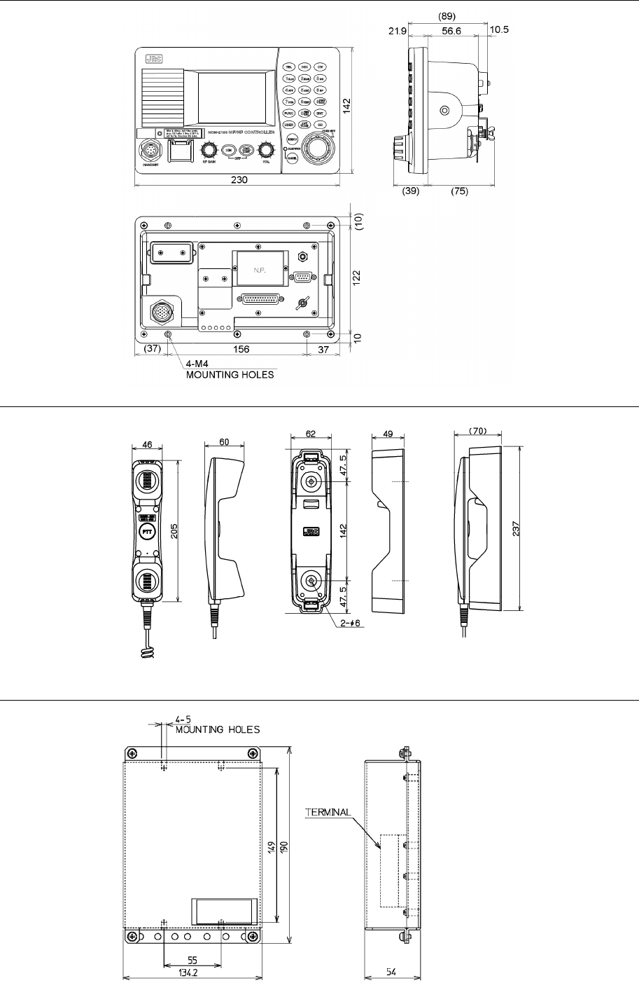
1-6
(3) MF/HF Controller (NCM-2150)
(4) Handset (NQW-261)
(5) Connection box (NQD-2250)
Unit: mm
Weight: Approx. 0.5 kg
Unit: mm
Weight: Approx. 1.3 kg
Mounting
hole
Unit: mm
Weight: Approx. 0.6 kg
Equipment Overview
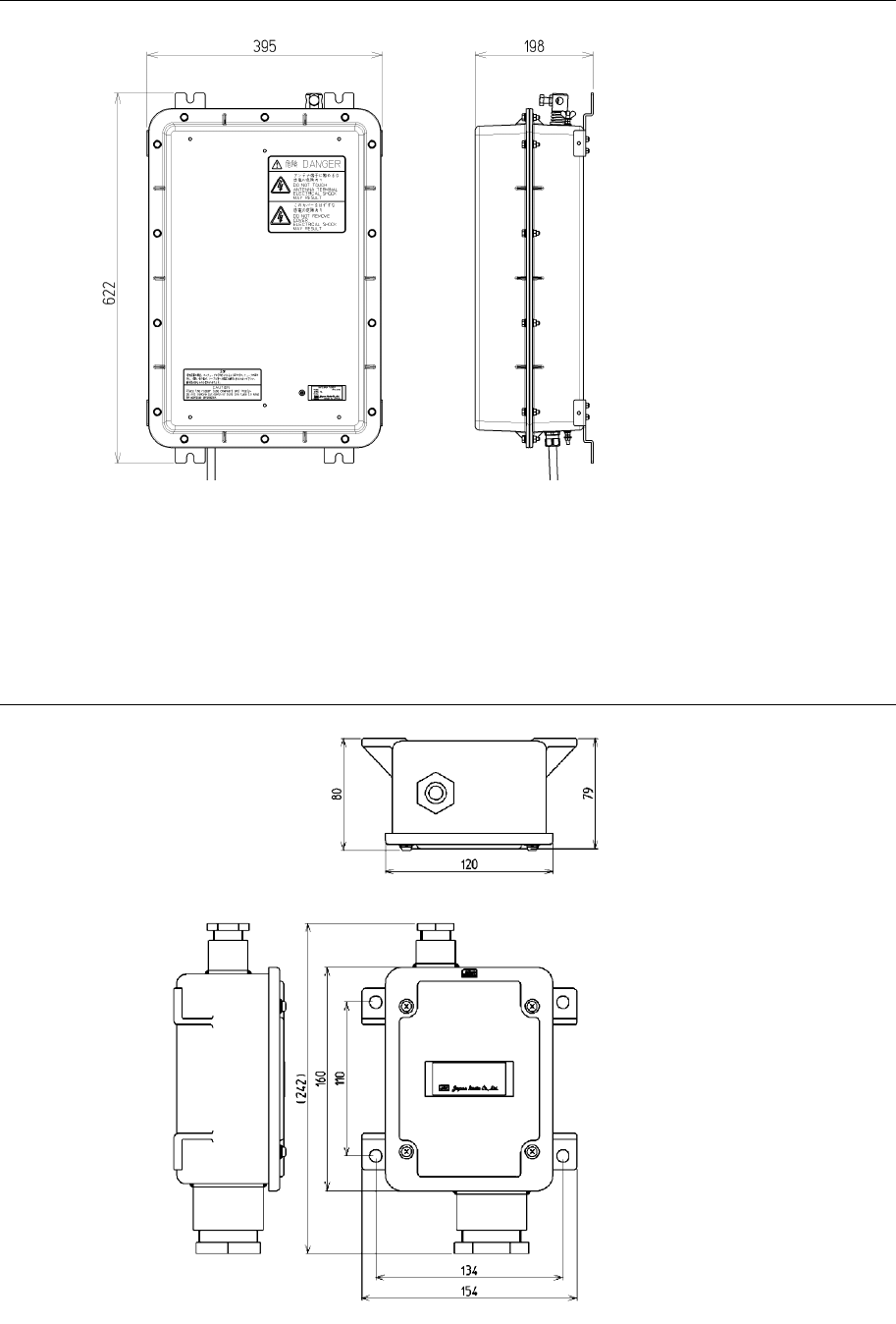
1-7
(6) Antenna Tuner (NFC-2250/2500)
(7) Junction Box (NQD-2253)
Unit: mm
Weight: Approx. 1.2 kg
Unit: mm
Weight: Approx. 10 kg/ 10 kg
Equipment Overview
1-8
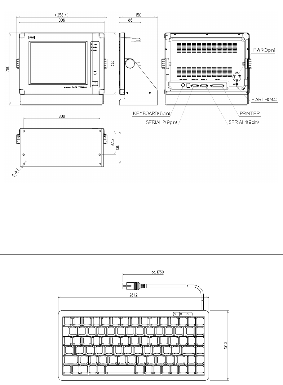
(8) Data Terminal (NDZ-227)
(9) Keyboard (NDF-369)
Unit: mm
Weight: Approx. 0.4 kg
Unit: mm
Weight: Approx. 4.6 kg
Equipment Overview
1-9
(10) Printer (NKG-800)
● Desktop type
(11) Printer (DPU-414)
● Desktop type
Unit: mm
Weight: Approx. 3.7 kg
Unit: mm
Weight: Approx. 0.6 kg
Equipment Overview
1-10
(12) Printer (NKG-91)
● Wall mount type
● Flash mount type
Unit: mm
Weight: Approx. 1.5 kg
Unit: mm
Weight: Approx. 0.8 kg
Equipment Overview
1-11
(13) Battery Charger (NBB-714)
(14) Battery Charger (NBB-724)
Unit: mm
Weight: Approx. 12 kg
Unit: mm
Weight: Approx. 8.6 kg
Equipment Overview
1-12
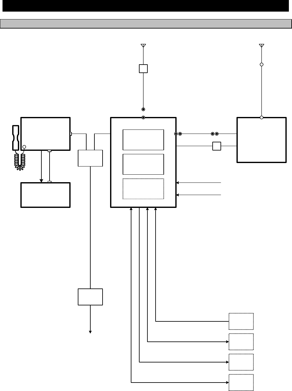
1.5 Block diagram
1.5.1 DSC model (JSS-2250/2500)
24V DC
200Ah
GPS
AME
RMS
(VDR)
DPYC-16
TTYCS- 1
MPYCS- 7
TTYCS- 1
TTYCS- 4
100V/220V AC
50/60Hz 1φ
NCH-321A
DMC
DPYC-25
RG-12/UY
RX/WKR ANT
TX
ANT
M-P-7
Tx antenna
Rx/WKR
antenna
TTYCS- 4
DPYC-2.5
7ZCJD
0343
(5m)
NQD-2250
Connection
box
NFC-2250/2500
Antenna tuner
TX ANT
Lead wire
TH-19/1.2
NCM-2150
MF/HF Controller
NQW-261
Handset
JQD-69C
Joint box
NQD-2250
Connection
box
Expansion controller
7ZCJD0254A
TTYCS- 4
DPYC-2.5
NKG-91
Printer
6.5V DC
NTD-2250/2500
Transceiver
NBD-2250/2500
Power supply
NBB-724
Battery charger
7ZCJD
0426
M-P-7
TTYCYS-4
NQD-2253
Junction
box
RG-10/UY
M-P-7/M-P-5
M-A-JJ
Equipment Overview
1-13
1.5.2 DSC/NBDP model (JSS-2250N/2500N)
RG-12/UY
7ZCJD
0426
M-P-7
M-P-7
Tx antenna
Rx/WKR
antenna
TTYCS- 4
DPYC-2.5
7ZCJD
0343
(5m)
NQD-2250
Connection
box
NFC-2250/2500
Antenna tuner
TX ANT
TTYCYS-4
Lead wire
TH-19/1.2
NQD-2253
Junction
box
NCM-2150
MF/HF Controller
NQW-261
Handset
JQD-69C
Joint box
RG-10/UY
M-P-7/M-P-5
M-A-JJ
NDZ-227
Data terminal
NDF-369
Keyboard
NKG-800
Printer
NQD-2250
Connection
box
Expansion controller
7ZCJD0419
6JNKD00100B
7ZCJD0388
7ZCSC0205A
TTYCS- 4
DPYC-2.5
GPS
AME
RMS
(VDR)
TTYCS- 1
MPYCS- 7
TTYCS- 1
TTYCS- 4
NCH-321A
DMC
NTD-2250/2500
Transceiver
NBD-2250/2500
Power supply
NBB-724
Battery charger
RX/WKR ANT
TX
ANT
24V DC
200Ah
DPYC-16 100V/220V AC
50/60Hz 1φ
DPYC-25
Equipment Overview
1-14
Names and Functions
2-1
2. NAMES AND FUNCTIONS
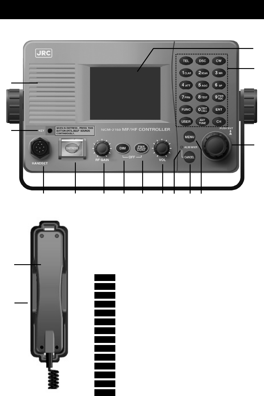
2.1 Controller (NCM-2150)
The controller parts and their functions are described below.
1. Internal loud speaker
2. Jack for telegraph in continuous wave (CW) mode
3. Black and white liquid crystal display unit
4. Numeric keypad (10-key) and function keys
In addition to entering numeric values, when combined with the
FUNC key, the keys have the following functions.
・ TEL ··· Sets TEL mode with the last or default frequency.
・ DSC ··· Sets DSC mode with the last or default frequency.
・ CW ··· Sets CW mode with the last or default frequency.
・ 1CLAR ··· Displays the setting screen for the clarifier.
・ 2SCAN ··· Displays the scan menu.
・ 3NR ··· Displays the setting screen for noise reduction.
・ 4ATT ··· Displays the setting screen for attenuation.
・ 5AGC ···
Displays the setting screen for automatic gain control.
・ 6SP ··· Turns speaker on or off.
・ 7PRN ··· Prints the specified screen.
・ 8TEST ··· Displays the self-diagnosis menu.
・ 9 ··· Switches Tx power between high, medium and low.
・ 0 ··· Displays the DSC test call menu.
・ FUNC ···
Enables 10-key functions or changes an active screen.
1
4
5
14 6 7 8 9 10 11 12 13
2
3
15
16
PWR
RDC
TEST
CALL

Names and Functions
2-2
・ ENT ····· Enter key.
・ USER ····· User defined key. Register a frequently used menu to open it quickly.
・ ····· Tunes the antenna.
・ CH ····· Sets the channel input mode (user channel, ITU channel, or free frequency).
5. Jog dial
- On the status display, rotating the jog dial changes the channel or Rx frequency.
- On the operating display, rotating the jog dial changes the frequency on the transceiver
setting screen, selects the event on the procedure list screen, or selects the handling menu
on the message/event control screen.
- On a menu or popup screen, rotating the jog dial moves the cursor position or screen
contents. When selecting a button or an item on the screen, rotate the jog dial until the
cursor is on it and then press the jog dial.
Pressing the jog dial works as with the Enter key.
6. Handset connector
7. DISTRESS key (Under a clear cover with spring)
When in distress, sends a DSC distress alert when pressed and held for 4 seconds.
8. RF GAIN control
Adjusts sensitivity level.
RF GAIN is set to maximum just after DSC or TLX mode is set, regardless of the
position of the control.
9. DIM (Dimmer) key
Adjusts dimmer level (Max → Typ → Min → Off) of the LCD display and key switches.
Additionally used to put into sleep mode by pressing it in combination with the key at the
same time (a confirmation screen is displayed).
・ The adjusted dimmer level is not saved. When the controller is powered off
and on again, the dimmer level is always set to Typ (default).
・ If a DSC message is received, the dimmer adjustment cycle becomes "Max →
Typ → Typ → Typ" while the receiving alarm is activated.
10. PWR/CONT (Power/Contrast) key
Turns on the equipment or changes the controller from sleep mode to standby. Once turned on,
this key is also used to adjust the LCD contrast.
11. VOL (Volume) control
Adjusts volume of built-in loud speaker.
12. ALM/WKR (Alarm/Watchkeeping receiver) lamp
Lights up red on any malfunction detected in the equipment or after sending a DSC distress alert,
or blinks red on receiving a DSC call. Lights green to indicate the DSC watchkeeping receiver is
operating while the equipment is in sleep mode.
13. CANCEL key
Cancels menus, a procedure on the operating display or stops alarms.
14. MENU key
Displays menu list.
15. Handset
When using in radiotelephone mode, press and hold the PTT key to talk.
16. Cradle (for handset)
ANT
TUNE
Note
Note
PWR
CONT
Note
Names and Functions
2-3
2.2 Controller’s display
The LCD screen on the controller changes according to current conditions. This section
describes the status display, operating display, FUNC menu, and main menu screens.
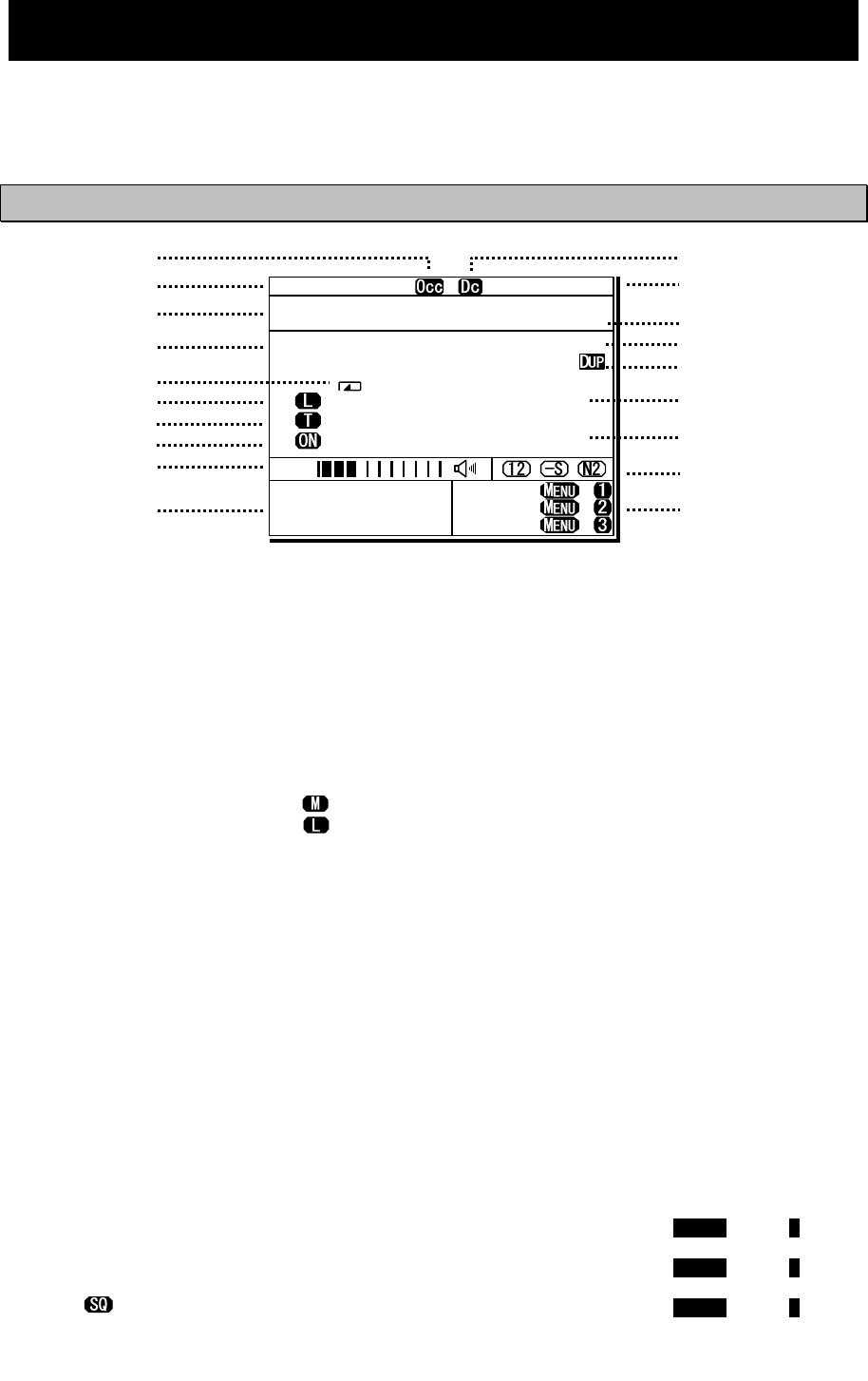
2.2.1 Status display
1. Occupied mark. Indicates another controller
has the access rights.
2. Indicates the ship's MMSI.
3. Indicates the ship's position and that time.
4. Indicates the communication mode and
channel.
5. Indicates the receiver is scanning.
6. Indicates the Tx power condition (reduction
settings) as follows.
z High : (Blank)
z Medium :
z Low :
7. Indicates the following conditions if Tx
frequency is not tuned.
z Not tuned : Blinks
z Tuning : Lights
z Tuned : (Blank)
8. Indicates transmission status (PA power).
9. When in reception or standby, indicates
strength of received signal (S meter), or
when in transmission, indicates strength of
transmitted signal in one of the pre-set
units shown below.
z Tx power (PWR)
z Antenna current (Ia)
z PA voltage (Vc)
z PA current (Ic)
z Key information (KEY)
Note: When transmitting in ARQ mode, KEY
is displayed regardless of the above
mentioned setting.
Additionally, the right icon indicates the
built-in loud speaker is on or off. The mark
of indicates the squelch is on.
10. Indicates the frequency (band) the DSC
watch keeping receiver is monitoring for
distress and safety calls.
11. Indicates the equipment is running on DC
power.
12. Indicates current time as follows:
z Universal time coordinated : UTC
z Local time : LT
13. Indicates the source of the ship's position
information as follows.
z External device (e.g. GPS) : EXT
z Manual input : MAN
z No input : OFFLINE
14. Indicates the user channel in use is
transmitted at the band power level
because the channel power is not
registered.
15. Indicates channel or frequency is duplex
for communicating with a coast station.
16. Indicates the reception frequency.
17. Indicates the transmission frequency. TX
mark is highlighted when transmitting.
18. Indicates the reception status (attenuation,
AGC, noise reduction).
19. Indicates the operation guidance (shortcut)
to send the DSC messages.
z NonDST: To send a non-distress alert,
holding down the MENU, press 1 key.
z DROBOS: To send a drobose call,
holding down the MENU, press 2 key.
z EdtDST: To edit & send a distress alert,
holding down the MENU, press 3 key.
TEL ITU- 401
4357.0
4065.0
RX kHz
TX kHz
NonDST: +
DROBOS: +
EdtDST: +
ID 431001234 23:59(UTC)
Pos 89゚59.0123'N
179゚59.6789'E@23:59 (EXT)
SIG
WKR scan bands:
2 4 6 8 12 16MHz
*
11
13
15
17
18
5
4
3
2
1
12
8
16
19
6
14
9
7
10
Names and Functions
2-4
2.2.2 Operating display
(1) General
After setting the frequency, pressing PTT key in TEL mode, sending/receiving messages in
DSC/TLX mode, and things like that, the controller shows the operating display as follows.
1. Indicates the MMSI and the latest position
and that time.
2. Indicates an focused screen with sign
and thick-frame, i.e. the operating display
is divided into three screens as below,
where the focused screen can be moved
using the FUNC key for clockwise.
3. Indicates the transceiver setting screen
similar to the status display. Icons on this
area are as follows.
z Scanning :
z Not tuned yet :
z Tx power reduction :
z Turned the PA ON :
z Attenuation (dB) :
z AGC (Fast/ Slow) :
z
Noise reduction (NR1/NR2/BC)
:
4. Indicates the S meter and watchkeeping
receiver monitoring frequencies mentioned
above.
5. Indicates the existing procedures. If the
procedure is under operation (active), A
mark is added in the box frame. Further, if
other procedures on hold exist, they are
indicated in the other box frames and are
selectable to operate at any time. And
while this screen is focused, the turning
dial animation is shown as below.
6. Indicates the content and the handling
menus of the procedure located at the top
of the procedure list screen.
During operating an active procedure, any functions such like the DSC automatic
acknowledgement become invalid to avoid the ongoing communication interruption.
ID 431001234 23:59(UTC)
Pos 89゚59.0123'N
179゚59.6789'E@23:59 (EXT)
Communicating on
TEL Rx:13077.0/Tx:12230.0kHz
Tip)Use FUNC to change op area.
[HLD][END]
AA
TEL
13077.0
12230.0
DUP
ID 431001234 23:59(UTC)
Pos 89゚59.0123'N
179゚59.6789'E@23:59 (EXT)
Communicating on
TEL Rx:13077.0/Tx:12230.0kHz
Tip)Use FUNC to change op area.
[HLD][END]
AA
TEL
13077.0
12230.0
DUP
3
1
2
5
6
Transceiver
setting
Procedure
list
Message/event
control
Note
4
Names and Functions
2-5
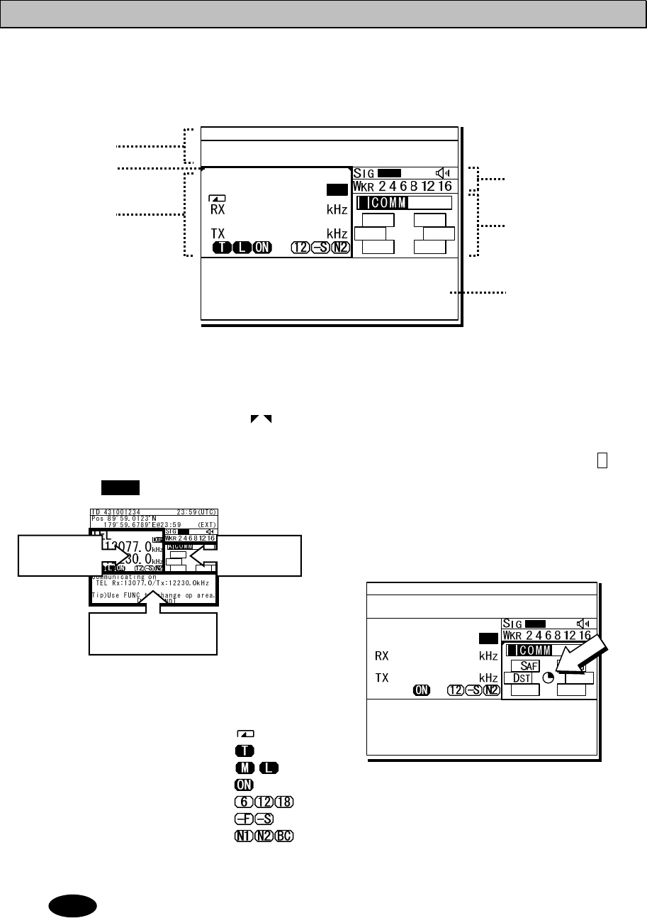
(2) Operating display of DSC calls
When communicating using DSC messages, the controller shows as follows.
1. Indicates the transceiver setting screen
similar to the status display mentioned
above.
2. Indicates the message type according to
the following components.
¾ Call direction : Calling event -
Called event -
¾ Category : RTN… routine
SAF… safety
URG… urgency
DST… distress
¾ Address type : IND… individual
ARE… area
GRP… group
¾ DST type : ALT… distress alert
RLY… distress relay
CNL… distress cancel
ACK… distress ack
¾ Other type : TST… safety test
POS… safety position
POLL… routine polling
EOS…
routine ind w/o ack
Additionally, indicates COMM if started
communication without using DSC.
3. Indicates procedures information of active
or on hold with the DSC categories or COM.
4. Indicates the message info as follows;
¾ Destination/source ID to comm with:
TxTO/RxID
¾ Address type:
IND, Area, GRP, All
¾ Category or DST type:
RTN, SAF, URG, DST
DISTRESS ALT, DST RLY,
¾ Other information:
ACK, NACK
5. Indicates the DSC message status with the
elapsed time of the top frame procedure.
Additionally the following special marks may
be indicated on this line.
E … Indicates when including the ECC
error in the message.
D … Indicates when the DSC procedure
is started by receiving a delayed
ACK without a calling message.
6. Indicates the message received frequency.
7. Indicates the subsequent frequency if exist.
8. Indicates the handling menus. This figure
shows the following menus.
¾ ACK : Accepts the call and sends ACK
¾ NCK : Sends “unable to comply”
¾ NEW : Sends ACK with new work FRQ
¾ INF : Indicates the detail info
¾ HLD : Makes the active proc on hold
¾ END : Terminates the procedure
- When sending the “able to comply” acknowledgement against the received
message requesting the TEL communication, lifting handset is also available as a
substitute for selecting the ACK handling menu.
- When selecting the NEW or NCK menu, the dedicated popup screen is appeared.
- When sending an acknowledgement automatically to the receiving calls such as
position request, safety test, polling, or the call requesting communication with
an invalid frequency, the above screen is shown and starts sending automatically.
After finishing it, that screen is closed automatically.
1
5
2
3
4
6
Note
7 8
Names and Functions
2-6
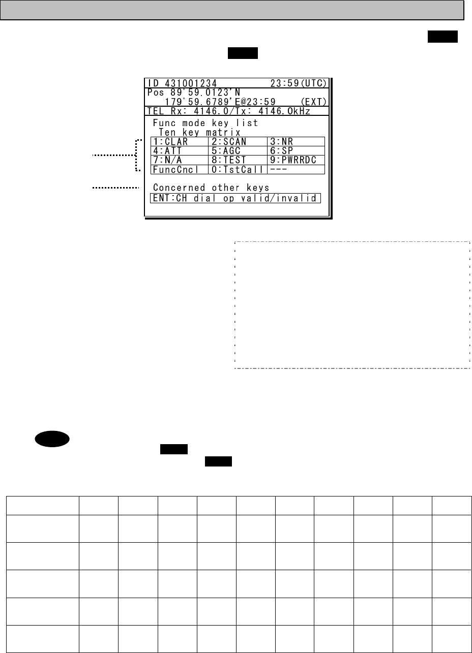
2.2.3 Function screen and key operations
The functions assigned to the number keys are temporarily enabled by pressing the FUNC
key in the status display or holding down the FUNC key and pressing the number key.
1. Indicates the enabled number key and its
function when the FUNC key is pressed in
the status display. Pressing the number
keys here operates the function for that
key as shown at the right.
1 CLAR : Displays the clarifier adjustment menu
2 SCAN : Displays the scan menu
3 NR : Displays the noise reduction menu
4 ATT : Displays the attenuation menu
5 AGC : Displays the AGC menu
6 SP : Turns the built-in loud speaker on or off
7 N/A : PRN is valid only on specific menus.
8 TEST : Displays the self-diagnosis menu
9 : Displays the Tx power reduction menu
0
TstC al l
: Displays the DSC test call menu
FuncCncl
: Closes this screen
2. Indicates that pressing ENT enables or disables the use of the jog dial to change the frequency
and channel in the status display.
- During the operating display mentioned above, the function screen is not appeared.
In this case the FUNC key alone is available to select the screen. However note
that the holding down the FUNC key and pressing the number key is also valid.
- In the following situations the function assigned to the function key cannot be used.
Equipment
status 1CLAR 2SCAN 3NR 4ATT 5AGC 6SP 7PRN 8TEST 9
P
WR
R
DC 0 TEST
CALL
DSC mode ● ●
While printing ● ● ● ● ● ● ● ● ● ●
During
self-diagnosis ● ● ● ● ● ● ● ● ● ●
While
scanning ● ● ●
While alarm
screen is
displayed ● ● ● ● ● ● ● ● ● ●
1
2
PWR
RDC
Note
Names and Functions
2-7
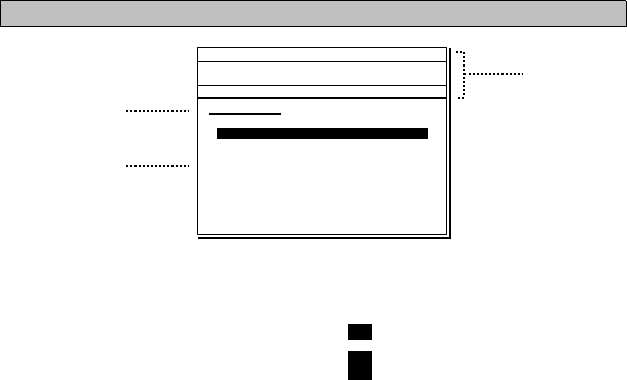
2.2.4 Menu screen
1. Indicates the current menu name.
2. Indicates the menu content. The cursor line
or position is highlighted. Select items with
the jog dial and press ENT to confirm.
3. Indicates the main radio information the
same as the status display. Also indicates
the following marks in the frequency
information area according to the
conditions.
T : Performing the antenna tuning
(Blinking means “Not tuned”.)
M : Tx power is Medium.
L : Tx power is low.
3
1
2
Main menu
1.DSC non-distress call
2.DSC drobose call
3.Editing a distress msg
4.DSC logs
5.Radio operation
6.Maintenance
7.Setup
0.Back
ID 431001234 23:59(UTC)
Pos 89゚59.0123'N
179゚59.6789'E@23:59 (EXT)
TEL Rx:13077.0/Tx:12230.0kHz
1.DSC non-distress call
Names and Functions
2-8
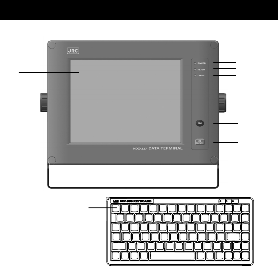
2.3 Data terminal(NDZ-227)
This section describes the name of each part in the data terminal and the function.
1. Color liquid crystal display (LCD) unit
2. POWER lamp
This lamp lights to green while operating the data terminal, and blinks during the sleep.
3. READY lamp
This lamp lights to green while serial communications are being normally done. And, when
abnormality occurs, it turns off.
4. COMM lamp
This lamp lights to green while communicating in ARQ or FEC mode.
5. DIM (Dimmer) key
This key adjusts the brightness of the LCD screen and the lamp by four stages (high, middle, low,
and off).
6. Connector for the USB memory with the water-proof rubber cap
Pull out the rubber cap and connect the USB memory.
7. Keyboard
7
1
2
5
6
3
4
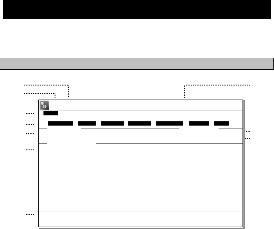
Names and Functions
2-9
2.4 Display of data terminal
The content displayed on the LCD screen in the data terminal is different according to the
situation. This section describes a regular screen, the telex communication screen, and the
message file edit screen.
2.4.1 Regular screen
1. Indicates the Tx and Rx frequencies.
2. Indicates the communication mode.
3. Indicates the main menu.
When pressing the Enter key, indicates
the drop-down menu of the main menu
pointed by the cursor.
※Telex mode only.
4. Indicates the conditions of the telex
communication.
※Telex mode only.
5. Indicates the scanning information in telex
mode. When restarting scanning after
sending a DSC Auto-ACK or powering
off/on, indicates “Running now” instead of
the detail information.
※Telex mode only.
6. Indicates the operation result such as the
self-diagnosis.
7. Indicates the guide according to the
cursor position. Moreover, the locating
faults are displayed if any errors occur.
z Information: MEM :Internal memory
z Information: KBD :Keyboard control
z Information: PRN :Printer
z Information: USB :USB Memory
8. Indicates that the connected USB memory
is available. Additionally, “ACS” is shown
if some time is needed to mount the USB
memory.
9. Indicates the antenna tuning condition.
z READY :Tuned
z NOT READY :Not tuned
10. Indicates the power reduction setting.
2
1 8
3
4
5
6
9
7
10
[TLX] Tx= 2174.5kHz/Rx= 2174.5kHz USB
File Tune Connect Service System Help
STATUS INFO
ST-BY
[No scanning] TUNER :[READY]
Tx.POWER :[HIGH]
Move the cursor to the item you want with ↑, ↓, →, ← then press Enter.
File manager.
Information:MEM KBD PRN USB (Press the <Alt>+I if you want to know detail.)
File
Free sig. ST-BY Calling Receive Rephasing Repeat Traf
Scanning info Tuner/Tx.POWER
Last status message
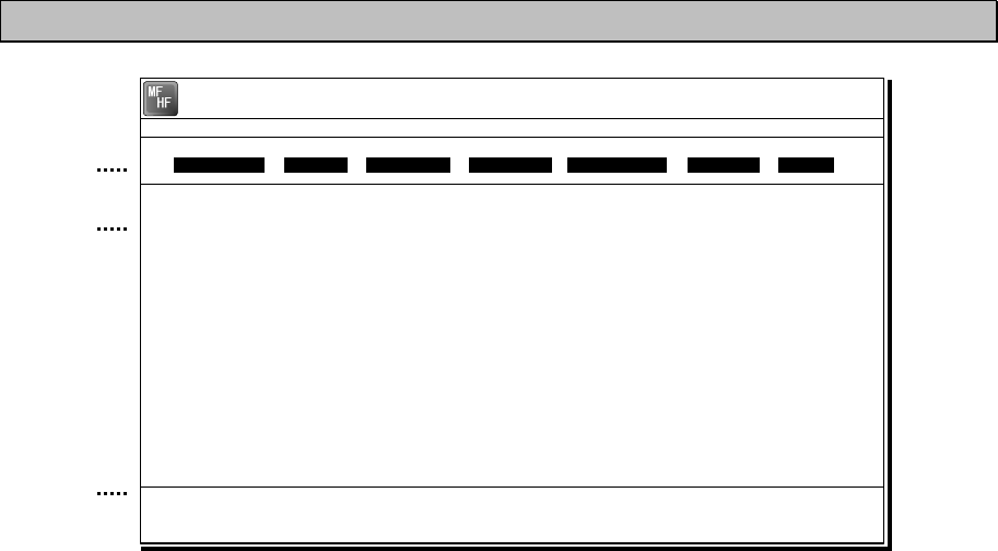
Names and Functions
2-10
2.4.2 Telex communication screen
1. Indicates the operating condition of the
telex communication from the left of each
segment as follows.
1) In the autotelex mode, when the free
channel signal of the coast station is
detected, indicates the “Free Sig”.
2) Indicates the communication mode
(ARQ/CFEC/SFEC).
※Indicates “ST-BY” in the standby
condition.
3) Indicates “Calling” at the master
station, and “Called” at the slave
station.
4) Indicates “Send” at the information
sending station, and “Receive” at the
information receiving station.
5) Indicates "Phasing" while calling and
connecting the communication
channel and “Rephasing” while
reconnecting the channel after the
channel is disconnected due to the
channel condition in ARQ mode.
6) Indicates “Repeat” in ARQ mode if
requested to send the each block or
the control signal again.
7) Indicates “Traf” while sending or
receiving information and “RQ” while
sending or receiving RQ signal.
2. Indicates the telex message or the name
of the executed function key.
3. Indicates the usable function keys guide.
Each meaning is as follows.
z F2 WRU : Requests the answer-
back code to the
corresponding station.
z F3 Hereis : Sends the answerback
code of own station.
z F4 TMS : Sends the date and the
time information.
z F5 Over : Exchange the sending
and the receiving
condition.
z F6 POLL : Acquires the sending
right if the correspond-
ing station (sending)
tries to finish the
communication in ARQ
mode.
※It is available only when the
corresponding station is using the
modem made of our company.
z F8 F.Send : Sends a message file.
z F10 Stop : Finishes the telex
communication.
1
2
3
[TLX] Tx= 2174.5kHz/Rx= 2174.5kHz USB
TELEX Terminal Window
ARQ
Message start...
F2 WRU | F3 Hereis | F4 TMS | F5 Over | F8 F.Send | F10 Stop
Free sig. ARQ Calling Send Rephasing Repeat Traf
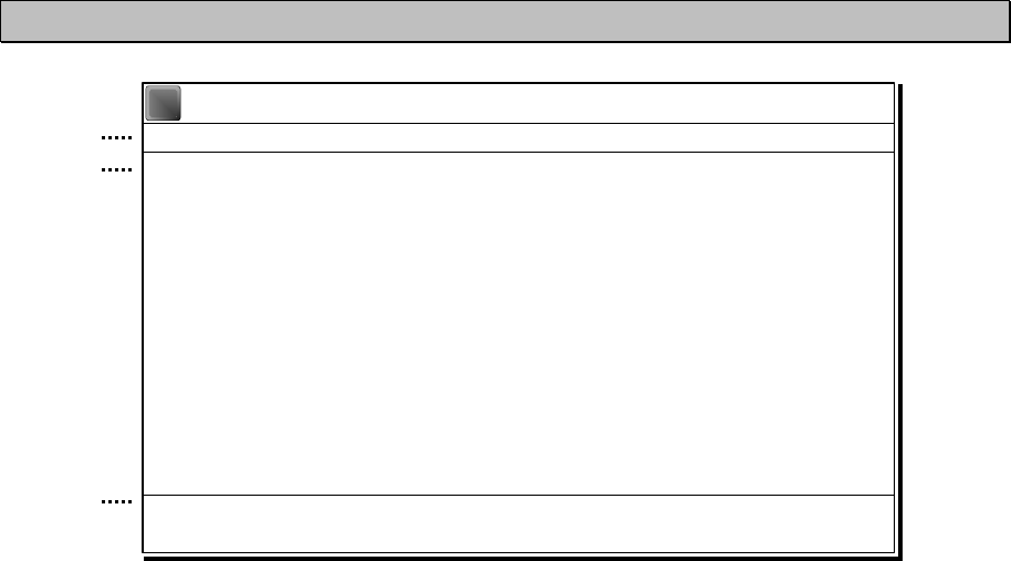
Names and Functions
2-11
2.4.3 Message file edit screen
1. Indicates the state of the edit screen as
follows.
z Editing telex file :File name
z Line :Line position of cursor
z Column :Row position of cursor
z Size :Capacity of file
z
Insert On/Overwrite
:
Input mode (insert/overwrite)
2. The message file is edited here.
3. The list of the function key is displayed by the
following content separately for two groups.
z Group 1
・ F1 :Insert On/Off
・ F2 :Ins_Line
・ F3 :Block
・ F4 :Del_Word
・ F5 :Del_Line
・ F6 :
・ F7 :Quit
・ F8 :Save As
・ F9 :Save & Quit
・ F10 :- Others -
z Group 2
・ F1 :Max Column
・ F2 :Set Tab
・ F3 :Undo_Char
・ F4 :Undo_Word
・ F5 :Undo_Line
・ F6 :Merge File
・ F7 :Find
・ F8 :Print out
・
F9 :Find/Replace
・ F10 :- Others -
1
2
3
[TLX] Tx= 2174.5kHz/Rx= 2174.5kHz USB
Editing telex file:001.TLX Line: 1 Column: 1 Size: 0 Insert On
[End of File]
F1:Insert Off F2:Ins_Line F3:Block F4:Del_Word F5:Del_Line
F7:Quit F8:Save As F9:Save & Quit F10: - Others -
MF
HF

Installation
3-1
3. INSTALLATION
CAUTION
To install this equipment, contact our service center or agents.
Special knowledge on selecting the place where the antenna is to be mounted and
setting the ID number (MMSI) assigned to the ship is required in addition to
installing the equipment.

Operation
4-1
4. OPERATION
This chapter describes basic operations of the controller and the data terminal,
radiotelephone communications, telex communications, DSC calling procedures, and
other radio functions.
4.1 Operation overview
4.1.1 Operation of the controller
Basically, the controller is operated with the numeric keypad (10key), the MENU key, and the jog
dial for other than the telex communication. The following is an overview of their operation.
z When two controllers are connected, only one controller having the access right can operate
the equipment except for sending a distress alert, changing audio volume, and changing
display conditions. (Unless otherwise mentioned, the instructions below are for the controller
with the access rights.)
z To obtain the access right at a controller without access rights, press ENT to get the access
right unless the other controller is being operated (PTT/KEY ON or menu operations).
z The DISTRESS key is always available. (The DISTRESS key has the highest priority.)
z On the status display or the operating display, the communication frequency or channel can
be set by using the number keys or if the transceiver setting screen is focused on, setting it
by rotating the jog dial is also available.
z Pressing the TEL DSC or CW key changes the communication mode. If the screen displays
in the menu, immediately shows the status display or the operating display, and also the
channel input mode changes to the free frequency mode. Additionally, the communication
mode can be changed to the AM mode to listen to the radio broadcasting or to the DATA
mode to communicate using the intership fax
z When the communication mode is set to TEL or CW, pressing the same communication mode
key turns the PA on and off. (When the PA is on, ON mark appears.)
z All functions can be accessed using the MENU key, jog dial, and the dedicated keys/controls.
(See the menu tree on the next page.) Further, screens in the menu tree indicated by
"Printable" can be printed from a printer connected to the controller or the data terminal by
pressing and holding the FUNC key and then pressing the 7PRN key.
z Pressing or pressing and holding the FUNC (function) key and a number key allows rapid
access to that function.
z There are two ways to access main menu items. After pressing the MENU key to display the
main menu, use either the jog dial to move the cursor to the desired item and press ENT to
select it, or select the item by pressing the respective number key. (Ex: For Self diagnosis
(6.1.1 Transceiver), press MENUÎ6SPÎ1CLARÎ1CLAR)
z Any menu can be assigned to the USER key to open it with a single touch of a button.
z Normally the key is always enabled.
z Pressing the CH key changes the channel input mode to the User ch, ITU ch or to the free
frequency. This key is enabled when showing the status display or the operating display.
z Pressing the CANCEL key in any menu moves the display up one level in the hierarchy (or to
the status display). The same results can be achieved by selecting "0. Back" when available
on-screen. Further, pressing the CANCEL key on an input line will clear the entered data.
z Pressing the MENU key in any menu opens the main menu. Also, pressing MENU while
in the main menu returns to the status display or the operating display.
z Dialog boxes (popup screens) are opened when necessary and operations can be done in
the dialog box.
z When using DSC calls, to distinguish the messages or conditions, some specific alarms are
provided as listed after the menu tree below.
ANT
TUNE
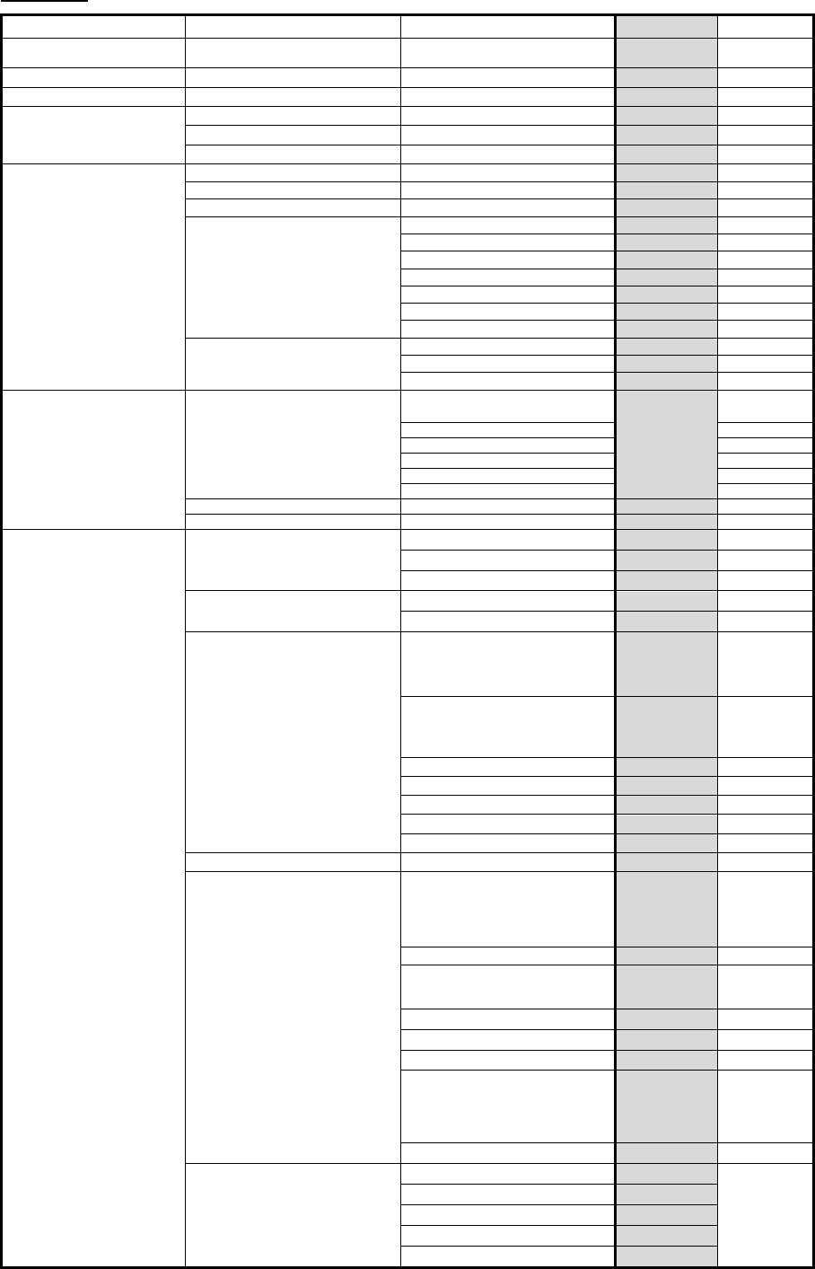
Operation
4-2
Menu tree
Main Menu Hierarchical Menu 1 Hierarchical Menu 2 Shortcut Key Note
1. DSC non-distress call MENU+1(RTN)
FUNC+0
(
Te s t
)
2. DSC drobose call MENU+2
3. Editing a distress msg MENU+3
4. DSC logs 4.1 Received distress (Received message screen) Printable
4.2 Received others (Received message screen) Printable
4.3 Transmitted calls
(Transmitted message screen)
Printable
5. Radio operation 5.1 User channel list (index) 5.1 User channel list (table) Printable
5.2 ITU channel list (index) 5.2 ITU channel list (table) Printable
5.3 Mode
5.4 Receiver 5.4.1 Auto gain control FUNC+5
5.4.2 Noise reduction FUNC+3
5.4.3 Attenuation FUNC+4
5.4.4 Clarifier FUNC+1
5.4.5 Squelch
5.4.6 CW bandwidth
5.4.7 Scan FUNC+2
5.5 Transmitter 5.5.1 Power FUNC+9
5.5.2 Tune power
5.5.3 Auto tune start
6. Maintenance 6.1 Self diagnosis 6.1.1 Transceiver
(ATU/PA/TRX/WKR MODEM)
FUNC+8
Printable
6.1.2 Controller/DTE Printable
6.1.3 Transceiver log Printable
6.1.4 Controller/DTE log Printable
6.1.5 DSC/NBDP loop Printable
6.1.6 Printout
6.2 Alarm information Alarm history Printable
6.3 Software version Printable
7. Setup 7.1 Date & time 7.1.1 Date
7.1.2 Present time
7.1.3 Display form
7.2 POS/TIME 7.2.1 Own position
7.2.2 UTC of position
7.3 My controller 7.3.1 LCD adjustment
1. Contrast
2. Dimmer
3. Screen saver
7.3.2 Sound
1. Operation
2. Notification level
3. Sidetone
FUNC+6(SP)
7.3.3 User key assign
7.3.4 Tx meter
7.3.5 Data transfer
7.3.6 Menu shutdown
7.3.7 CH search ref
7.4 User channels (index) 7.4 User channels (table) Printable
7.5 DSC/WKR condition 7.5.1 Automatic ACK
1. Test call
2. Position RQ call
3. Polling call
4. Individual call
7.5.2 WKR scanning FRQ
7.5.3 DSC alarm setting
1.
Safety/Routine RX ALM
2. Distress RX ALM
7.5.4 Medical use
7.5.5 Neutral use
7.5.6 Group-ID
7.5.7 Inactivity timeout
1. ACKed distress alert
2. RCVed other distress
3. Non-distress call
4. Other communications
7.5.8 DSC call list
7.6 Option 7.6.1 Connection Printable
7.6.2 Data out
7.6.3 Baudrate
7.6.4 Flow control
7.6.5 Print direction

Operation
4-3
DSC alarm specifications
The following table summarizes the alarm characteristics when communicating particularly in the
DSC mode.
Reason for the alarm Sound Increase Shutdown
Receiving a new distress
event
Two tones of
2200Hz(250ms) and 1300Hz(250ms)
Yes Manually
Acknowledging a received
distress event
Two tones of
2200Hz(500ms) and 1300Hz(500ms)
No Manually
Acknowledging a sent own
distress event
Two tones of
2200Hz(500ms) and 1300Hz(500ms)
No Manually
Receiving a new urgency
event
Intermittent tones of
2200Hz(250ms) and silence(250ms)
Yes Manually
Acknowledging a sent
urgency event
Intermittent tones of
2200Hz(500ms) and silence(500ms)
No Manually
Receiving a new safety or
routine event
Two tones of
784Hz(1s) and 392Hz(1s)
Yes Automatically
(10s)
Acknowledging a sent safety
or routine event
Intermittent tones of
784Hz(1s) and silence(1s)
No Automatically
(10s)
Receiving a DSC message
pertinent to an ongoing event
Intermittent tones of
494Hz(100ms), silence(100ms) and
494Hz(1s)
No Automatically
(1 cycle)
Pressing the dedicated
distress button
An intermittent tone of
2000Hz(500ms) and silence(500ms)
No ---
If receiving a DSC message with the ECC error, the alarm is stopped automatically.
However if the same DSC messages are received repeatedly and the every error is
corrected at last, the original alarm may be sounded.
Note

Operation
4-4
4.1.2 Operation of the data terminal
Basically, the every function concerning the telex mode such as ARQ/FEC communication or
scanning can be operated from the data terminal.
● To connect and install the data terminal, setup the 7.6 Option menu of the controller.
● To set the communicate mode to the telex mode, press the Enter key of the keyboard.
Additionally, that operation acquires the access right if the controller connected to that data
terminal does not have the access right.
● Every function of the data terminal can be operated from the main menu displayed on a
regular screen, excluding the screen of communication modes other than the telex, telex
communicating screen, the telex file editing screen.
● Because the short-cut key to the table of next page is allocated in each item of the main
menu or the drop down menu, it is possible to execute it easily according to few procedures.
● The guide of the item shown with the cursor is basically displayed under the screen in the
data terminal.
● While displaying the menu screen on the controller, the data terminal cannot be operated
temporally. Similarly, the controller cannot be operated during the telex communication
except the operations of TEL DSC CW and DISTRESS keys.
● Besides the telex communication in ARQ/FEC mode, the data terminal has other functions
such as editing telex messages and the station list, setup of the radio condition, or setup of
the display color of the screen.
● The communication using ARQ mode can be started with a specific radio station by inputting
the selcal number (ID) and the work frequency.
● The communication using CFEC mode can be started as the broadcasting by inputting the
work frequency.
● The communication using SFEC mode can be started as the broadcasting for limited
receivers by inputting the selcal number (group ID) and work frequency.
● The telex communication channel can be set by specifying ARQ or FEC in the DSC message.
In this case, the telex communication may be started without inputting 9 digits selcal number
(ID) and work frequency because those have been already set by the DSC calling.
● Up to 20 stations can be registered in the station list.
● The self-diagnosis of the data terminal is executed from the controller as well as other units.
● The controller outputs the printing data from the printer connected to the data terminal.
● The condition of the data terminal such as the startup or the sleep is synchronized to the
controller connected or the system.
● When the data terminal detects any error(s) concerning to the internal flash memory, the
keyboard, the printer or the connected USB memory, immediately shows the popup screen
and the Information is displayed on the bottom line on the screen until the error is fixed.

Operation
4-5
Menu tree in data terminal
Main Menu Short-cut
Key Drop-down Key Short-cut
Key Remarks
File F Edit new file N
Edit existing file E
Rename file R
Delete file D
Copy file C
Initialize USB I
Remove USB U
Tune T Frequency list F Printable
ITU channel set C
Tx/Rx frequency set Q
Tx tune U
Scanning start (stop) S
Connect C ARQ A
CALL C Option
AUTOTELEX T Option
CFEC F
SFEC S
Service S Call logging history C Printable
Station list S Printable
Station database D Printable
Destination list L Option
Sunspot number N
MUF calculation M
Clear status window R
System Y Config C
Scan speed S
NBDP setup N
Help H Software version
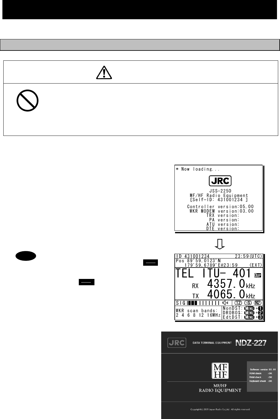
Operation
4-6
4.2 Basic communications procedure
The following describes basic radio communication procedures.
4.2.1 Turning on the power
CAUTION
Do not turn off the equipment when at sea because the SOLAS Convention
requires keeping watch on distress and safety frequencies at all times.
Always listen to 2187.5 kHz and 8414.5 kHz, and one or more of the following
frequencies; 4207.5 kHz, 6312.0 kHz, 12577.0 kHz, or 16804.5 kHz.
In class B mode, it is necessary to keep watch only on 2187.5 kHz.
■ Procedure ■
1
1
1.
.
.
Make sure the equipment is connected to a
power source and turn on the breakers on the
power supply.
¾ The controller, transceiver and data terminal
start the internal check.
¾ After the check is finished correctly, the status
display appears and becomes receiving
condition (standby) on the receiving frequency
showing.
- When turning on the controller or the
equipment in sleep mode, press
key for one second.
- Pressing key for 6 seconds
makes the system reset to restart.
- When two controllers are connected,
and one controller is turned on from
sleep mode, the status display is
displayed immediately without
checking operations.
- The start screen of the data terminal
is as shown at right.
- If errors are detected during the
operation check, the message is
displayed. Please inform JRC or our
agent of the error contents.
Note
PWR
CONT
PWR
CONT
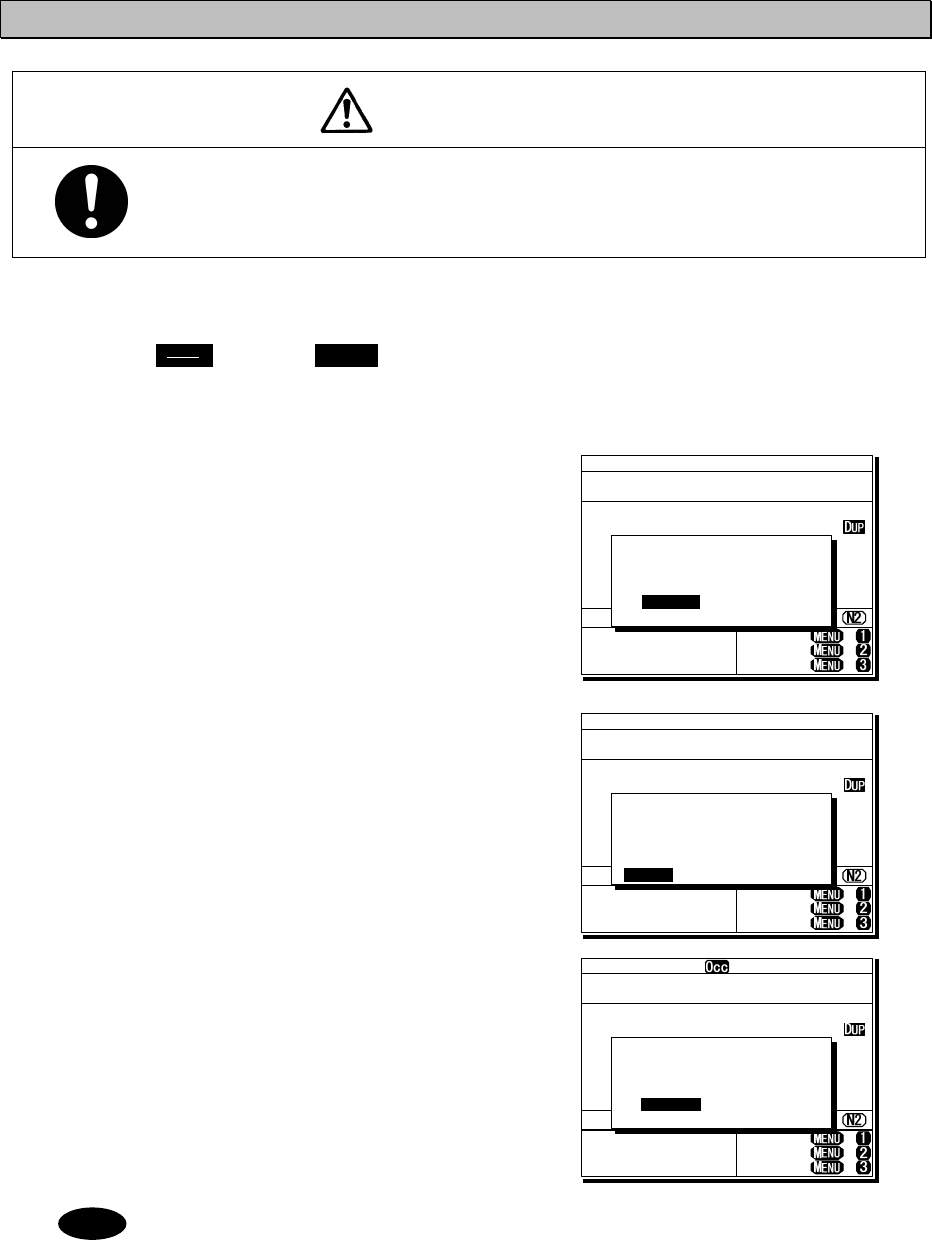
Operation
4-7
4.2.2 Turning off the power/ Putting into sleep mode
CAUTION
When completely turning off the power to the equipment, turn off the breakers
on the power supply.
■ Procedure ■
Press the key and DIM key
simultaneously.
After that, the power-off process is activated
according to the controllers' status.
z When using only one controller
Select the desired item below on the
popup screen shown at right
⋅ [OK]: Turns off the power. (Puts into
sleep (energy saving) mode.)
⋅ [Cancel]: Returns to the previous screen.
z When using two controllers
On a controller with access rights, select
the desired item below on the popup
screen shown at right
⋅ [EQP]: Turns off the power. (Puts into
sleep (energy saving) mode.)
⋅ [CTRL]: Puts the controller into sleep
mode and gives access rights
to another controller.
⋅ [Cancel]: Returns to the previous screen.
On a controller without access rights,
select the desired item below on the
displayed popup screen at right
⋅ [OK]: Puts one controller into sleep
mode.
⋅ [Cancel]: Returns to the previous screen.
¾ In sleep mode, the equipment changes to the following statuses.
⋅ If all the equipment goes to sleep, the ALM lamp lights green to indicate
the DSC watch keeping receiver is on and operating.
⋅ The POWER lamp of the data terminal blinks.
⋅ If a distress or urgent DSC message is received, the equipment turns on
automatically and sounds an alarm.
¾ Turn off both the AC and DC breakers if turning off the power at the
NBD-2250/2500 Power supply.
Note
TEL ITU- 401
4357.0
4065.0
RX kHz
TX kHz
NonDST: +
DROBOS: +
EdtDST: +
ID 431001234 23:59(UTC)
Pos 89゚59.0123'N
179゚59.6789'E@23:59 (EXT)
SIG
WKR scan bands:
2 4 6 8 12 16MHz
OK to sleep the
MF/HF equipment?
[ OK ] [Cancel]
[ OK ]
PWR
CONT
TEL ITU- 401
4357.0
4065.0
RX kHz
TX kHz
NonDST: +
DROBOS: +
EdtDST: +
ID 431001234 23:59(UTC)
Pos 89゚59.0123'N
179゚59.6789'E@23:59 (EXT)
SIG
WKR scan bands:
2 4 6 8 12 16MHz
OK to sleep the MF/HF
equipment, or
only this controller?
[EQP] [CTRL] [Cancel]
[EQP]
TEL ITU- 401
4357.0
4065.0
RX kHz
TX kHz
NonDST: +
DROBOS: +
EdtDST: +
ID 431001234 23:59(UTC)
Pos 89゚59.0123'N
179゚59.6789'E@23:59 (EXT)
SIG
WKR scan bands:
2 4 6 8 12 16MHz
OK to sleep this
controller?
[ OK ] [Cancel]
[ OK ]
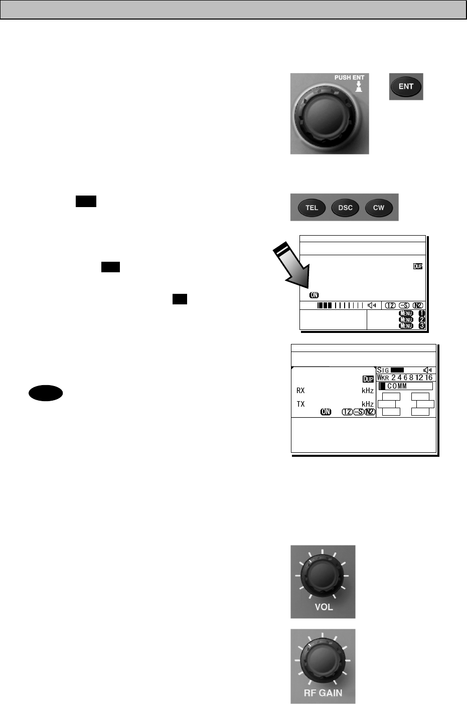
Operation
4-8
4.2.3 Communicating in radiotelephone mode
Use the handset to communicate in radiotelephone mode.
■ Procedure ■
1
1
1.
.
.
When operating on a controller without
access rights (OCC is displayed), press the
jog dial to obtain the access rights.
Unless the controller with access rights is being
used, the access rights are acquired and the OCC
display on the screen disappears.
2
2
2.
.
.
Press the TEL key.
¾ The communication mode is set to TEL and
the previous frequency (or the default
frequency at just after turning on) is set.
¾ Pressing the TEL key again turns the
power to the PA on and off.
¾ If the power to the PA is on, ON is displayed
as shown at right.
3
3
3.
.
.
Set the frequency for making calls in
radiotelephone mode.
- When setting a frequency, the screen
becomes operating display as shown
at right.
- The frequency is set on the receiving
status in the status display or the
operating display. For details, see
"4.3.1 Setting the communication
frequencies" and "4.3.2 Setting the
communication channels".
- See the frequency for making calls
in the appendix "11.4 ITU channel
list (TEL/CW/TLX)".
4
4
4.
.
.
Adjust the volume of the loudspeaker by
turning the volume control.
5
5
5.
.
.
Turn the RF GAIN control to an appropriate
reception level.
TEL ITU- 401
4357.0
4065.0
RX kHz
TX kHz
NonDST: +
DROBOS: +
EdtDST: +
ID 431001234 23:59(UTC)
Pos 89゚59.0123'N
179゚59.6789'E@23:59 (EXT)
SIG
WKR scan bands:
2 4 6 8 12 16MHz
Note
ID 431001234 23:59(UTC)
Pos 89゚59.0123'N
179゚59.6789'E@23:59 (EXT)
Communicating on
TEL Rx: 4360.0/Tx: 4068.0kHz
Tip)Use FUNC to change op area.
[HLD][END]
AA
TEL
4360.0
4068.0
ITU- 402
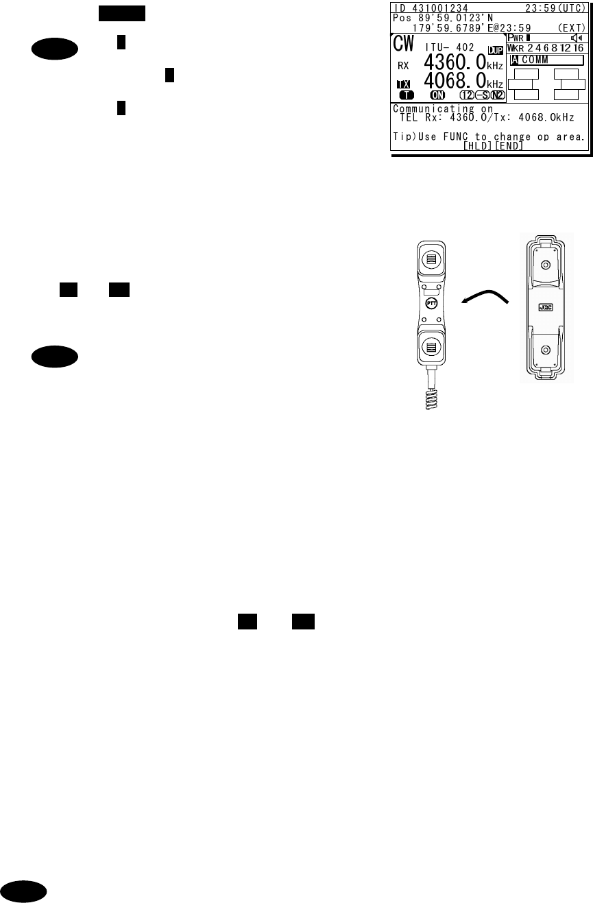
Operation
4-9
6
6
6.
.
.
Press the key to tune the antenna.
- T blinks if the transmission frequency
is not tuned.
- Even if T is not displayed, tune the
antenna before making a call.
- T lights during tuning. It goes out
after tuning.
7
7
7.
.
.
Lift the handset from the cradle.
8
8
8.
.
.
Press the PTT key to talk.
The TX and ON marks appear on the screen to
show the equipment is transmitting. Releasing the
PTT key returns it to receiving.
Pressing the PTT key turns on the power
to the PA automatically.
9
9
9.
.
.
When finished communicating, return the
handset to the cradle.
■ Making a radiotelephone call ■
1
1
1.
.
.
Set a frequency the station to be called is monitoring.
2
2
2.
.
.
Lift the handset from the cradle.
3
3
3.
.
.
Press the PTT key, check that TX and ON are displayed and make a call as described
below.
z Say the name of the station being called ... Repeat 3 times.
z Say "This is..."
z Say own ship name ... Repeat 3 times.
z If necessary, indicate your working frequency.
z "over"
4
4
4.
.
.
Release the PTT key to listen.
5
5
5.
.
.
Start communicating according to the response. When changing frequencies, make
sure that no other stations are using the indicated working channel.
- When transmitting from your own station, always press the PTT key while talking.
- On a simplex channel, always say "over" just before releasing the PTT key.
- Always say "out" when terminating communications.
Note
ANT
TUNE
Note
Note
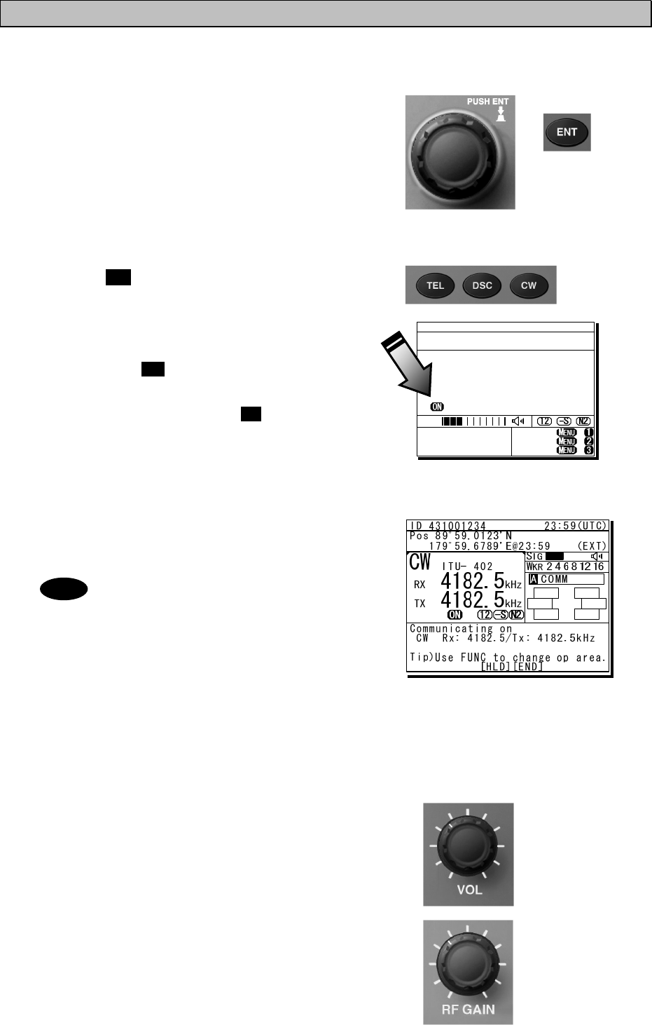
Operation
4-10
4.2.4 Communicating in CW mode
Use a CW keyer to communicate in CW mode.
■ Procedure ■
1
1
1.
.
.
When operating on a controller without
access rights (OCC is displayed), press the
jog dial to obtain the access rights.
Unless the controller with access rights is being
used, the access rights are acquired and the OCC
display on the screen disappears.
2
2
2.
.
.
Press the CW key.
¾ The communication mode is set to CW and
the previous frequency (or the default
frequency at just after turning on) is set.
¾ Pressing the CW key again turns the
power to the PA on and off.
¾ If the power to the PA is on, ON is displayed
as shown at right.
3
3
3.
.
.
Set the frequency for making calls in CW
mode.
- When setting a frequency, the screen
becomes operating display as shown
at right.
- The frequency is set on the receiving
status in the status display. For
details, see "4.3.1 Setting the
communication frequencies" and
"4.3.2 Setting the communication
channels".
- See the frequency for making calls
in the appendix "11.4 ITU channel
list (TEL/CW/TLX)".
4
4
4.
.
.
Adjust the volume of the loudspeaker by
turning the volume control.
5
5
5.
.
.
Turn the RF GAIN control to an appropriate
reception level.
CW ITU- 401
4182.0
4182.0
RX kHz
TX kHz
NonDST: +
DROBOS: +
EdtDST: +
ID 431001234 23:59(UTC)
Pos 89゚59.0123'N
179゚59.6789'E@23:59 (EXT)
SIG
WKR scan bands:
2 4 6 8 12 16MHz
Note
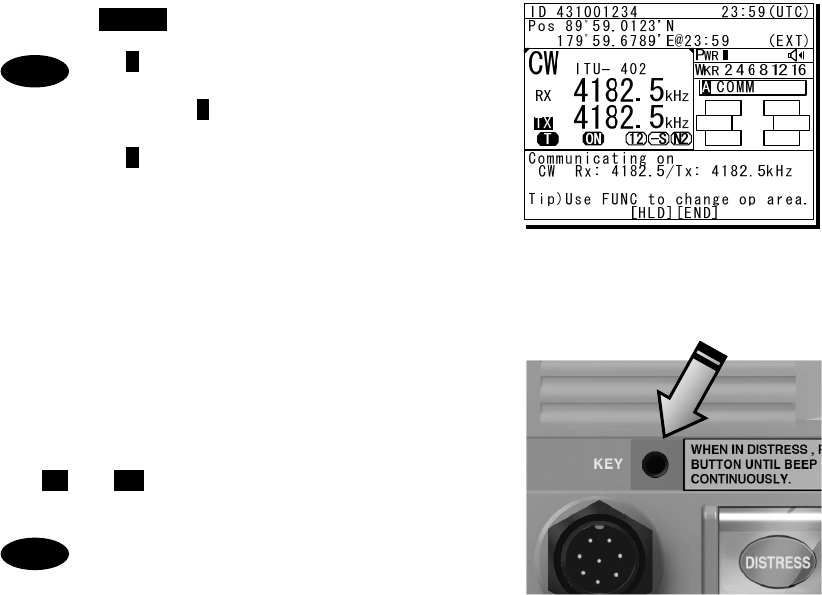
Operation
4-11
6
6
6.
.
.
Press the key to tune the antenna.
- T blinks if the transmission frequency
is not tuned.
- Even if T is not displayed, tune the
antenna before making a call.
- T lights during tuning. It goes out
after tuning.
7
7
7.
.
.
Communicate in CW mode using the CW
keyer connected to the KEY jack on the
controller as shown in the figure to the right.
The TX and ON marks appear on the screen to
show the equipment is transmitting.
- After keying on, turns on the PA
power automatically.
- For the sidetone setting, see "5.3.2
Sound settings".
Note
Note
ANT
TUNE
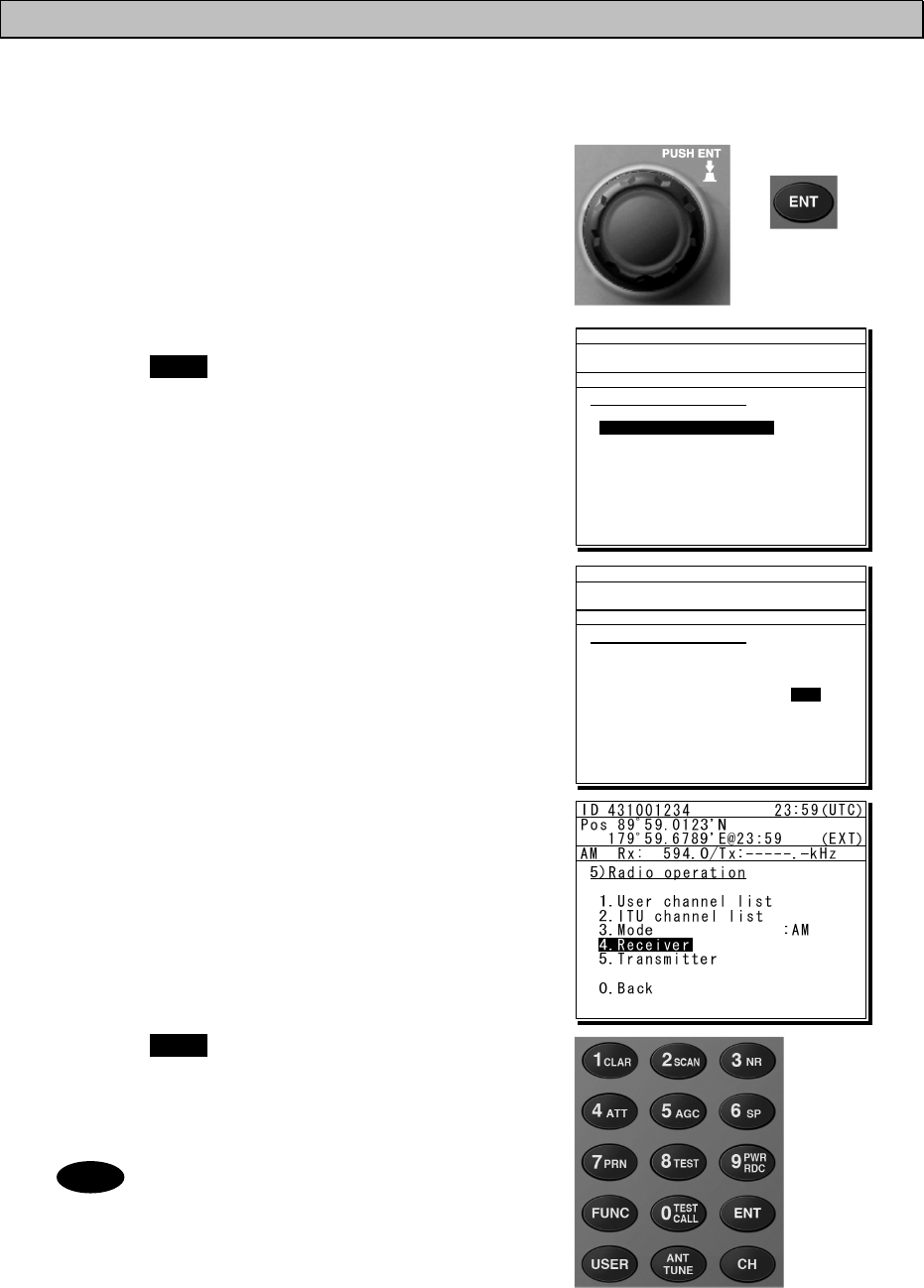
Operation
4-12
4.2.5 Receiving AM broadcasts
It is possible to listen to the radio in AM mode.
■ Procedure ■
1
1
1.
.
.
When operating on a controller without
access rights (OCC is displayed), press the
jog dial to obtain the access rights.
Unless the controller with access rights is
being used, the access rights are acquired
and the OCC display on the screen
disappears.
2
2
2.
.
.
Press the MENU key, and through
hierarchical menus, select 5. Radio
operation.
3
3
3.
.
.
Move the cursor to 3. Mode, and press
ENT.
Move the cursor to the right as shown in the
figure at right to select a communication mode.
4
4
4.
.
.
Turn the jog dial to select AM, and press
ENT.
The communication mode is set to AM and the
previous frequency (or the default frequency at
just after turning on) is set.
5
5
5.
.
.
Press the MENU key twice to return to the
status display and if required, input an AM
broadcast frequency using the numeric keys.
Then press ENT to receive the broadcast.
- Adjust the reception level and
volume by turning the VOL and RF
GAIN knobs according to the
reception conditions.
- The AM mode is for reception only so a
transmission frequency is not shown.
Additionally, if AM is selected during
blinking “T” (ATU does not tuned), the
condition remains even after changing
to the AM mode.
Note
ID 431001234 23:59(UTC)
Pos 89゚59.0123'N
179゚59.6789'E@23:59 (EXT)
TEL Rx:13077.0/Tx:12230.0kHz
5)Radio operation
1.User channel list
2.ITU channel list
3.Mode :TEL
4.Receiver
5.Transmitter
0.Back
1.User channel list
ID 431001234 23:59(UTC)
Pos 89゚59.0123'N
179゚59.6789'E@23:59 (EXT)
TEL Rx:13077.0/Tx:12230.0kHz
5)Radio operation
1.User channel list
2.ITU channel list
3.Mode :TEL
4.Receiver
5.Transmitter
0.Back
TEL
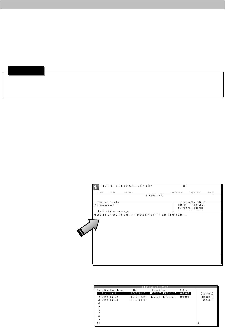
Operation
4-13
4.2.6 Communicating in telex mode (TLX)
When communicating in the telex mode, the data terminal is used. In the telex communication,
the ARQ (Automatic Repeat reQuest) mode and FEC (Forward Error Correction) mode are
available to communicate between two stations and to broadcast respectively. Additionally in the
FEC mode, there are two modes of the CFEC (Collective Forward Error Correction) mode for
unspecified receivers and SFEC (Selective Forward Error Correction) mode for specified
receivers, which are selectable according to the purpose.
After starting the telex communication, always use the data terminal until to stop it even
though the controller can terminate that communication with END option forcibly.
4
4.
.2
2.
.6
6.
.1
1
ARQ mode operation
To start the ARQ communication, make a call of the station by inputting the SELCAL number (4
digits for the coast station, 5 digits for the ship station or 9 digits) and the work frequency. After
initiating the call, when receiving the response from the called station and the communication
channel is established, the ARQ communication will be available.
■ Procedure ■
1
1
1.
.
.
If displaying the message of "Press Enter key to get the access right in the NBDP
mode…" on the data terminal, press Enter key on the keyboard.
The operation of the data
terminal becomes possible in
the telex mode, except when
the controller is used.
2
2
2.
.
.
On the main menu and the dropdown menu, select Connect Î ARQ with Enter key.
¾ The registered station list is
displayed.
¾ When selecting [Manual] on
this station list, the ID and
frequency or ITU channel
can be input manually.
Attention
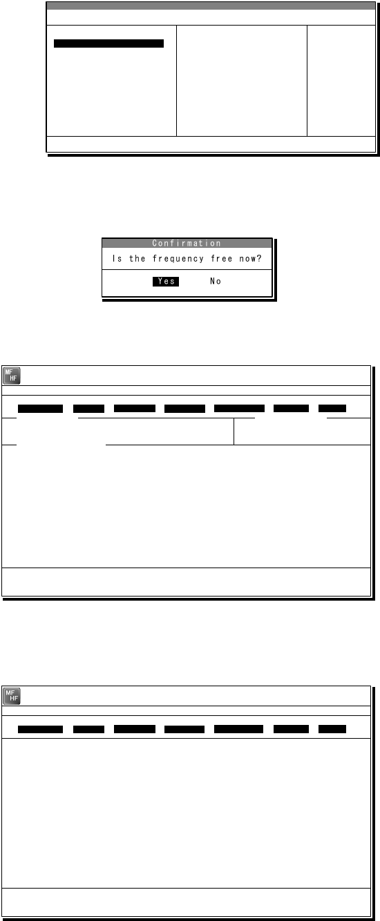
Operation
4-14
3
3
3.
.
.
Select the station to be called with the cursor, and press Enter key.
¾ The frequency list of the selected
radio station is displayed.
¾ If the position of the station is
registered, the MUF (maximum
usable frequency) is displayed in the
lowest line as a reference to select
the frequency. Also, the MUF can be
calculated by the menu of Service Î
MUF calculation.
4
4
4.
.
.
Select the work frequency with the cursor, and press Enter key.
¾ The selected frequency is set and the
antenna is tuned to the frequency.
¾ The message as shown at right is
displayed to confirm that the channel
is busy.
5
5
5.
.
.
Select Yes and press Enter key to start the call at the selected frequency.
Calling of the station is started
with the ARQ mode.
6
6
6.
.
.
When receiving the periodic reply from the called station and the communication
channel is established, th e ARQ communication will be available.
¾ The screen as shown at
right is displayed.
¾ If receiving no response
within one minute, the
calling will be ceased
automatically. In this case,
the same call is inhibited
for about one minute.
Frequency list
Name : [Station 01 ] ID : [004310123] Loc : [N33゚45' E138゚12']
No. Tx.F Rx.F No. Tx.F Rx.F
1 4202.5 4202.5 11 22354.5 22354.5 [Set]
2 4205.0 4205.0 12 25193.0 25193.0 [Print]
3 6300.5 6300.5 13 25208.0 25208.0 [Cancel]
4 6303.0 6303.5 14
5 8396.5 8396.5 15
6 8399.0 8399.0 16
7 12560.0 12560.0 17
8 16785.0 16785.0 18
9 18893.0 18893.0 19
10 22352.0 22352.0 20
MUF: 9MHz, Range: 2537Miles, Sunspot: 14
1 4202.5 4202.5
[TLX] Tx= 2174.5kHz/Rx= 2174.5kHz USB
File Tune Connect Service System Help
STATUS INFO
ST-BY
[No scanning] TUNER :[READY]
Tx.POWER :[HIGH]
ARQ: 20 AUG,2010 17:15
Station:[Station 01] ID:[004310123] Loc:[N33゚45'E138゚12']
*Waiting for transmitter ready
*Received TX-READY signal
F10 Stop
Free sig. ARQ Calling Send Phasing Repeat Traf
Scanning info Tuner/Tx.POWER
Last status message
[TLX] Tx= 2174.5kHz/Rx= 2174.5kHz USB
Station ID:[004310123]
TELEX Terminal Window
ARQ
Message start...
F2 WRU | F3 Hereis | F4 TMS | F5 Over | F8 F.Send | F10 Stop
Free sig. ARQ Calling Send Rephasing Repeat Traf
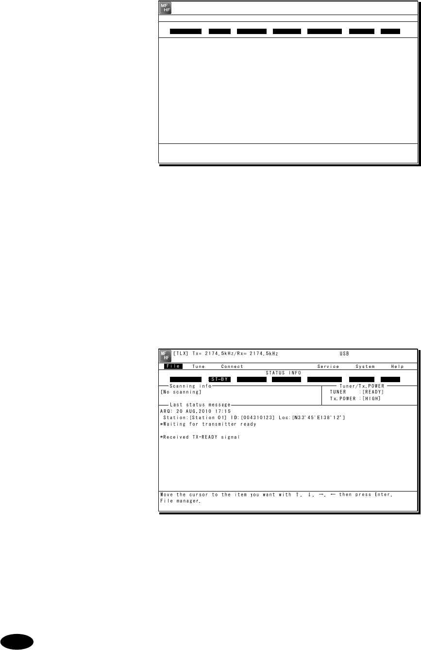
Operation
4-15
7
7
7.
.
.
The characters typed with the keyboard can be transmitted in sequence. And all of the
characters displayed on the screen are printed out on the printer.
¾ In the ARQ mode, it is
possible to alternate the
information sending station
(ISS) and the information
receiving station (IRS).
¾ While “Send” is displayed on
the segment that shows the
operation status, the own
station is ISS and able to
send a message.
¾ After sending a message,
send “+?” to give the sending
right to the IRS.
¾ While the condition is IRS, the
sending right can be acquired
by pressing F5 Over without
waiting for “+?” from ISS.
Further, refer to the chapter 2
for other function keys.
¾ Besides alphabets and the
figures, following signs can
be input from the keyboard.
- ? : ( ) . , ‘ = / +
Note: As the alphabets, capital
letters only are available.
8
8
8.
.
.
To finish the communication, press F10 Stop key.
¾ When receiving the reply to the
request for the end of
communication, returns to the
standby condition.
¾ F10 Stop is always available
while communicating regardless
of ISS/ IRS. Note that if
pressing the F10 key during
IRS condition, the station
becomes ISS temporally to
send the end of communication.
¾ When pressing the F10 Stop
key during sending a message,
the sending message buffer is
cleared at once and initiates
the end of communication
process.
¾ When POLL is set at IRS and
the end of communication is
requested by ISS, the IRS can
acquire the sending right
without ending the
communication.
When receiving the ARQ call from another station during standby condition, the
operation under the communication is basically similar.
Note
[TLX] Tx= 2174.5kHz/Rx= 2174.5kHz USB
Station ID:[004310123]
TELEX Terminal Window
ARQ
Message start...
THE QUICK BROWN FOX JUMPS OVER THE LAZY DOG 1234567890.
THE QUICK BROWN FOX JUMPS OVER THE LAZY DOG 1234567890.
THE QUICK BROWN FOX JUMPS OVER THE LAZY DOG 1234567890.
THE QUICK BROWN FOX JUMPS OVER THE LAZY DOG 1234567890.
END OF TEST
F2 WRU | F3 Hereis | F4 TMS | F5 Over | F8 F.Send | F10 Stop
Free sig. ARQ Calling Send Rephasing Repeat Traf
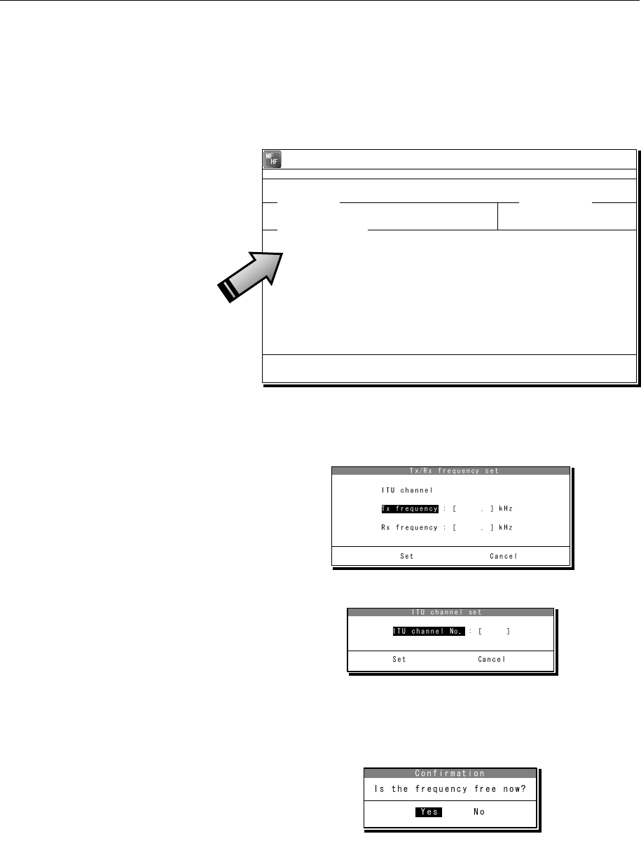
Operation
4-16
4
4.
.2
2.
.6
6.
.2
2
CFEC mode operation
(1) Sending with CFEC
Messages can be sent as a broadcast on the selected work frequency using the CFEC mode.
■ Procedure ■
1
1
1.
.
.
If displaying the message of "Press Enter key to get the access right in the NBDP
mode…" on the data terminal, press Enter key on the keyboard.
The operation of the data
terminal becomes possible in
the telex mode, except when
the controller is used.
2
2
2.
.
.
On the main menu and the dropdown menu, select Connect Î CFEC with Enter key.
¾ Input the frequency or ITU
channel on the screen as
shown at right.
¾ To input the frequency, press
Enter key to move the cursor to
the right.
¾ To input the ITU channel, select
the ITU channel button and press
Enter key to display the specific
screen as shown at right. Then
press Enter key to move the
cursor to the right.
3
3
3.
.
.
Input the work frequency or ITU channel, and press Enter key.
¾ The selected frequency is set and the
antenna is tuned to the frequency.
¾ The message as shown at right is
displayed to confirm that the channel
is busy.
[TEL] Tx= 2174.5kHz/Rx= 2174.5kHz USB
File Tune Connect Service System Help
STATUS INFO
[No scanning] TUNER :[READY]
Tx.POWER :[HIGH]
Press Enter key to get the access right in the NBDP mode...
Scanning info Tuner/Tx.POWER
Last status message
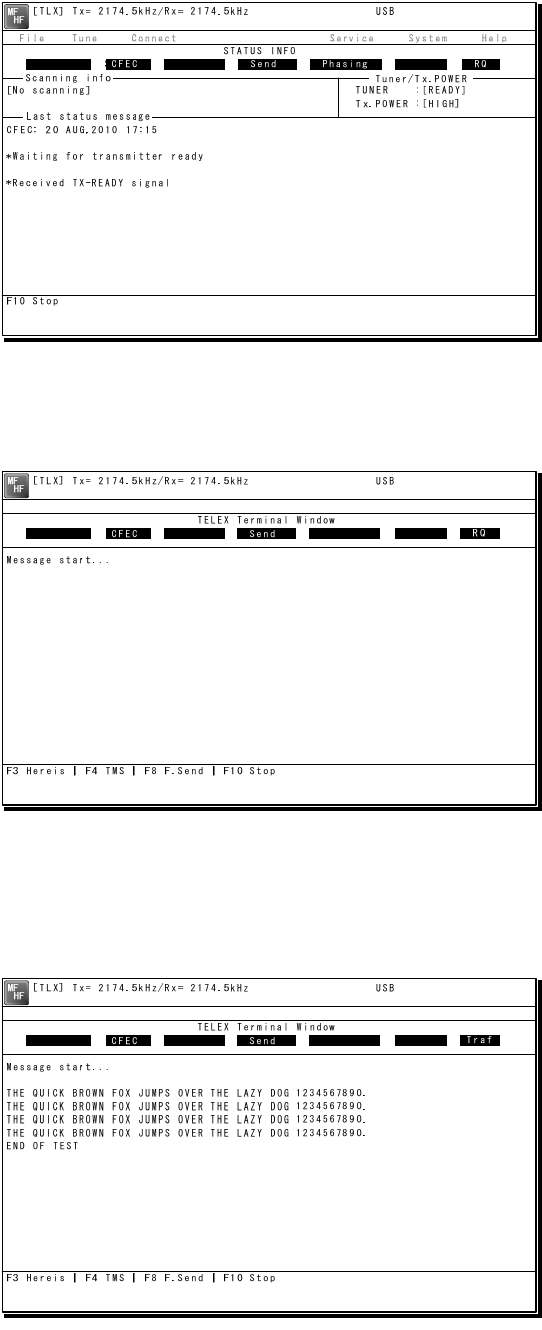
Operation
4-17
4
4
4.
.
.
Select Yes and press Enter key to start the call at the selected frequency.
Sending the phasing signal is
started with the CFEC mode.
5
5
5.
.
.
After sending the phasing signal for about 15 seconds, the message sending using
the CFEC mode will be available.
The screen as shown at right
is displayed.
6
6
6.
.
.
The characters typed with the keyboard can be transmitted in sequence. And all of the
characters displayed on the screen are printed out on the printer.
¾ Refer to the chapter 2 for the
function key.
¾ Besides alphabets and the
figures, following signs can
be input from the keyboard.
- ? : ( ) . , ‘ = / +
Note: Only the capital letter
can be used for the
alphabet.
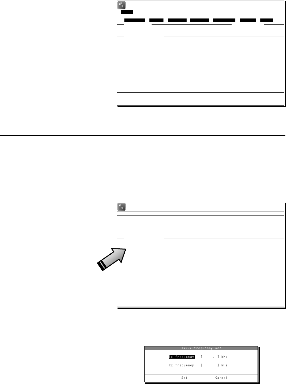
Operation
4-18
7
7
7.
.
.
To finish the communication, press F10 Stop key.
¾ After sending the end of
communication for about five
seconds, returns to the
standby condition.
¾ When pressing the F10 Stop
key during sending a
message, the sending
message buffer is cleared at
once and initiates the end of
communication process.
(2) Receiving CFEC broadcasting
CFEC broadcasting messages can be received on the selected work frequency.
■ Procedure ■
1
1
1.
.
.
If displaying the message of "Press Enter key to get the access right in the NBDP
mode…" on the data terminal, press Enter key on the keyboard.
The operation of the data
terminal becomes possible in
the telex mode, except when
the controller is used.
2
2
2.
.
.
On the main menu and the dropdown menu, select Tune Î Tx/Rx frequency set with
Enter key.
¾ The screen as shown at right
is displayed.
¾ To input the frequency, press
Enter key to move the cursor
to the right.
¾ To select the frequency from
the frequency list, select
Tune Î Frequency list and
open the frequency list of
either one of radio stations.
[TEL] Tx= 2174.5kHz/Rx= 2174.5kHz USB
File Tune Connect Service System Help
STATUS INFO
[No scanning] TUNER :[READY]
Tx.POWER :[HIGH]
Press Enter key to get the access right in the NBDP mode...
Scanning info Tuner/Tx.POWER
Last status message
[TLX] Tx= 2174.5kHz/Rx= 2174.5kHz USB
File Tune Connect Service System Help
STATUS INFO
ST-BY
[No scanning] TUNER :[READY]
Tx.POWER :[HIGH]
CFEC: 20 AUG,2010 17:15
*Waiting for transmitter ready
*Received TX-READY signal
Move the cursor to the item you want with ↑, ↓, →, ← then press Enter.
File manager.
File
Free sig. ST-BY Calling Receive Rephasing Repeat Traf
Scanning info Tuner/Tx.POWER
Last status message
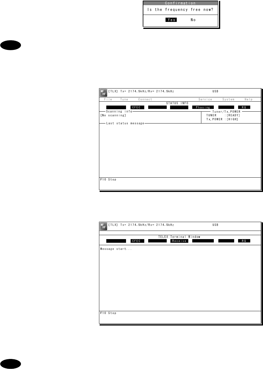
Operation
4-19
3
3
3.
.
.
Input the receiving frequency of the CFEC broadcasting, and press Enter key.
The antenna is tuned to the frequency
and the message as shown at right is
displayed.
The transmitting frequency is set simultaneously by the above procedure, but in
this case the frequency is meaningless. So selecting Yes and pressing Enter
would be right.
4
4
4.
.
.
When receiving the phasing signal, initiates the CFEC receiving condition.
The segment of the operation
status shows receiving the
phasing signal.
5
5
5.
.
.
When receiving the message start code (the carriage return and the line feed),
initiates the message reception.
¾ All of the characters displayed
on the screen are printed out
on the printer.
¾ If detected the character error,
the error correction with the
time-diversity is performed,
but upon the channel quality,
the error would be beyond the
capacity and the error code
(asterisk) would be displayed.
¾ To finish the reception, press
F10 Stop key. Note that, if
receiving the phasing signal
continuously, the CFEC
receiving would be restarted
just after finishing.
- If the "Collective FEC receiving” setting (System Î NBDP setup) is off,
neither the CFEC broadcasting nor the SFEC broadcasting are received.
- Receiving the CFEC broadcasting can be started even if on the way of the
message because the phasing signal would be interrupted for every 100
characters. Afterwards, the reception of the message starts as soon as
detecting the message start code (the carriage return and the line feed).
Note
Note
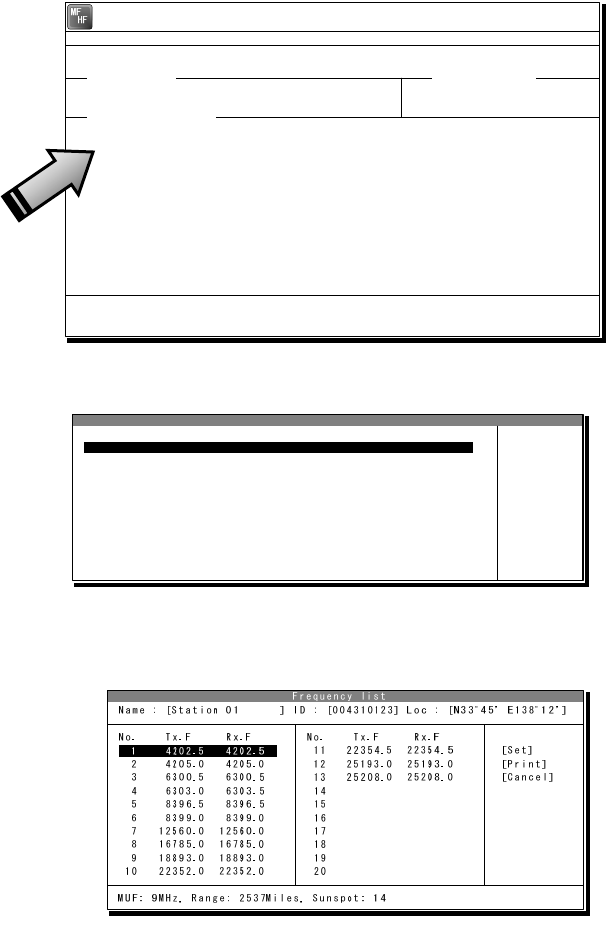
Operation
4-20
4
4.
.2
2.
.6
6.
.3
3
SFEC mode operation
Messages can be sent to the specific stations as a broadcast on the selected work frequency
using the SFEC mode. Additionally, regarding the SFEC reception, refer to the previous section
because it is similar to the CFEC reception.
■ Procedure ■
1
1
1.
.
.
If displaying the message of "Press Enter key to get the access right in the NBDP
mode…" on the data terminal, press Enter key on the keyboard.
The operation of the data
terminal becomes possible in
the telex mode, except when
the controller is used.
2
2
2.
.
.
On the main menu and the dropdown menu, select Connect Î SFEC with Enter key.
¾ The registered station list is
displayed.
¾ When selecting [Manual] on
this station list, the ID and
frequency or ITU channel
can be input manually.
3
3
3.
.
.
Select the station to be called with the cursor, and press Enter key.
¾ The frequency list of the selected
radio station is displayed.
¾ If the position of the station is
registered, the MUF (maximum
usable frequency) is displayed in
the lowest line as a reference to
select the frequency. Also, the
MUF can be calculated by the
menu of Service Î MUF
calculation.
Station selection
No. Station Name ID Location F.Sig
1 Station 01 004310123 N33゚45' E138゚12' DOTDOT [Select]
2 Station 02 004311234 N37゚22' E135゚51' DOTDOT [Manual]
3 Station 03 431012345 [Cancel]
4
5
6
7
8
9
10 ↓
1 Station 01 004310123 N33゚45' E138゚12' DOTDOT
[TEL] Tx= 2174.5kHz/Rx= 2174.5kHz USB
File Tune Connect Service System Help
STATUS INFO
[No scanning] TUNER :[READY]
Tx.POWER :[HIGH]
Press Enter key to get the access right in the NBDP mode...
Scanning info Tuner/Tx.POWER
Last status message
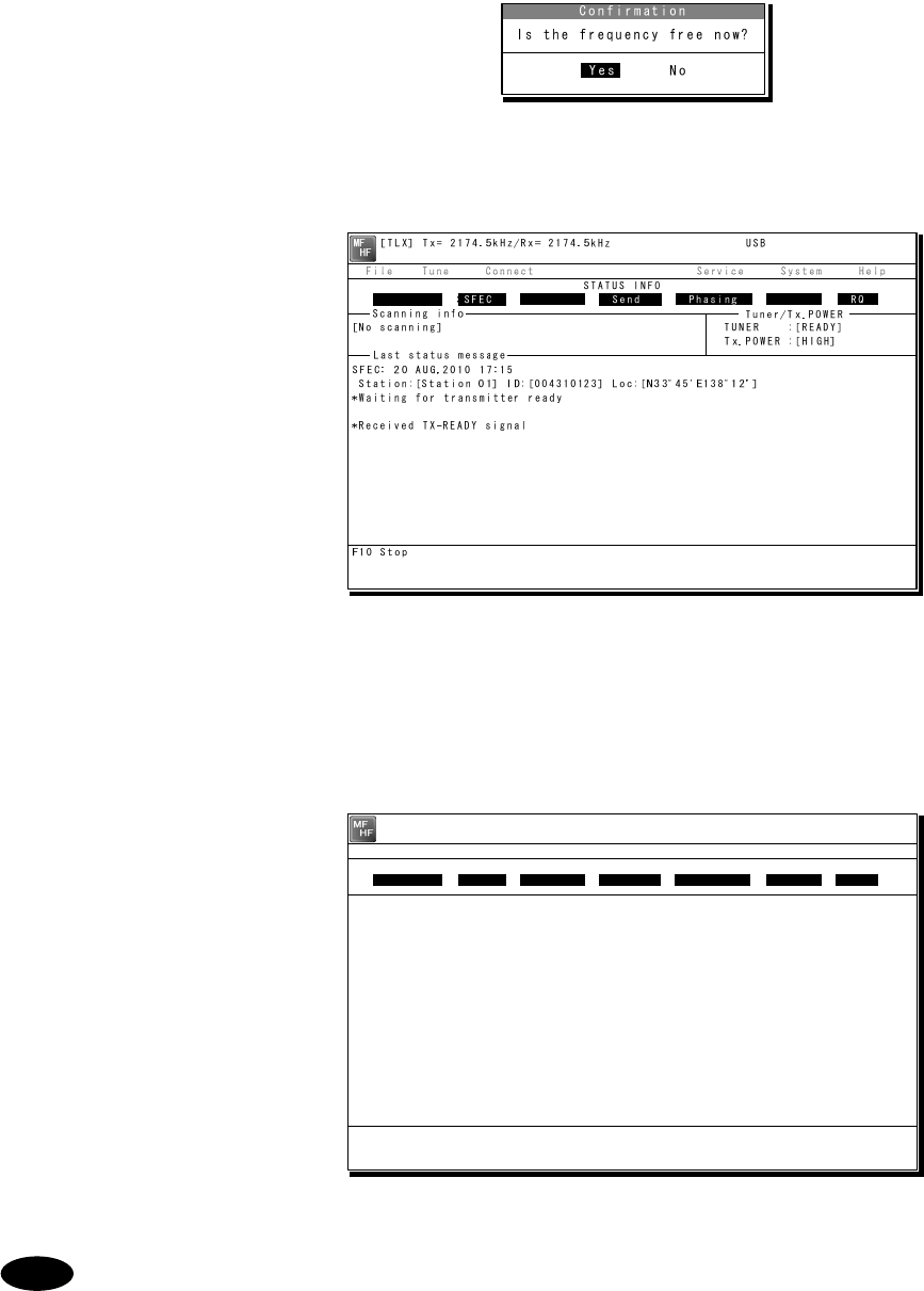
Operation
4-21
4
4
4.
.
.
Select the work frequency with the cursor, and press Enter key.
¾ The selected frequency is set and the
antenna is tuned to the frequency.
¾ The message as shown at right is
displayed to confirm that the channel
is busy.
5
5
5.
.
.
Select Yes and press Enter key to start the call at the selected frequency.
¾ The SFEC broadcasting is
started.
¾ First, the phasing signal same
with CFEC mode is sent.
6
6
6.
.
.
After sending the phasing signal followed by the SELCAL number, the message
sending using the SFEC mode will be available.
The screen as shown at right
is displayed.
The following procedure is the same as the CFEC mode.
Note
[TLX] Tx= 2174.5kHz/Rx= 2174.5kHz USB
Station ID:[004310123]
TELEX Terminal Window
ARQ
Message start...
F3 Hereis | F4 TMS | F8 F.Send | F10 Stop
Free sig. SFEC Calling Send Rephasing Repeat RQ

Operation
4-22
4
4.
.2
2.
.6
6.
.4
4
Editing telex messages
When communicating in the telex mode, the message file can be sent, which is prepared
beforehand as follows.
■ Procedure ■
1
1
1.
.
.
If displaying the message of "Press Enter key to get the access right in the NBDP
mode…" on the data terminal, press Enter key on the keyboard.
The operation of the data
terminal becomes possible in the
telex mode, except when the
controller is used.
2
2
2.
.
.
On the main menu and the dropdown menu, select File Î Edit new file with Enter key.
¾ The editing screen is
displayed as shown at right.
¾ To edit an existing file, select
File Î Edit existing file.
3
3
3.
.
.
Make the message with the keyboard.
¾ Besides alphabets and the figures, following signs can be input from the keyboard.
- ? : ( ) . , ‘ = / +
¾ Only the capital letter can be used for the alphabet.
¾ When the number of characters for each line becomes more than 70 or a specified number,
line feed is automatically inserted.
¾ When pressing the Tab key, inserts the space of the number set by F2 Set tab is inserted.
4
4
4.
.
.
Press F9 (Save & Quit) key when saving the message the file and finishing editing.
After closing the editing screen, returns to the regular screen.
[TEL] Tx= 2174.5kHz/Rx= 2174.5kHz USB
File Tune Connect Service System Help
STATUS INFO
[No scanning] TUNER :[READY]
Tx.POWER :[HIGH]
Press Enter key to get the access right in the NBDP mode...
Scanning info Tuner/Tx.POWER
Last status message
[TLX] Tx= 2174.5kHz/Rx= 2174.5kHz USB
Editing telex file:001.TLX Line: 1 Column: 1 Size: 0 Insert On
[End of File]
F1:Insert Off F2:Ins_Line F3:Block F4:Del_Word F5:Del_Line
F7:Quit F8:Save As F9:Save & Quit F10: - Others -

Operation
4-23
- The function keys available for the edit screen and the content are as follows.
● Group 1
・ F1 :Insert On/Off ··············· Sets the input condition to the insert mode by
pressing it while Insert On is displayed. And sets the
input condition to the overwrite mode by pressing it
while Insert Off is displayed. Current conditions are
indicated on the upper-right corner of the screen.
・ F2 :Ins_Line······················ Add a line to the line of the cursor position.
・ F3 :Block ·························· Indicates the following block menu.
・ Top-marker of block:
Specifies the cursor position for a starting point
of the block.
・ Bottom-marker of block:
Specifies the cursor position for a ending point
of the block.
・ Remove markers:
Releases the specification of the block.
・ Copy Block:
Copies and pastes the character string specified
in the block onto the cursor position.
・ Move block:
Moves the character string specified in the block
to the line position of the cursor.
・ Delete block:
Deletes the character string specified in the
block.
・ Go to the block:
Moves the cursor to the starting point of the
block.
・ F4 :Del_Word ···················· Deletes the word at the cursor position.
・ F5 :Del_Line ····················· Deletes the line at the cursor position.
・ F6 :( N/A)
・ F7 :Quit ···························· Finishes editing without saving the message file.
・ F8 :Save As ······················ Saves the message file with the new name.
・ F9 :Save & Quit ················ Saves the message file by overwriting and finishes
editing.
・ F10 :- Others - ···················· Assigns the group 2 to the function keys.
● Group 2
・ F1 :Max Column ················ Specifies the column width of a line.
・ F2 :Set Tab ······················· Specifies the tab position on the edit screen.
・ F3 :Undo_Char ·················· Insert the character erased at the end to the cursor
position.
・ F4 :Undo_Word ················· Insert the word erased with F4 Del_Word to the
cursor position.
・ F5 :Undo_Line ·················· Insert the line erased with F5 Del_Line to the line of
the cursor position.
・ F6 :Merge File ·················· Selects an existing message file to merge to the
message file under the edit.
・ F7 :Find ···························· Searches a specified character string.
・ F8 :Print_out ····················· Prints the message file under the edit.
・ F9 :Find/Replace ··············· Searches a specified character string and replaces it
with another character string.
・ F10 :- Others - ···················· Assigns the group 1 to the function keys.
Note
Operation
4-24
- Besides editing messages mentioned above, the following items in the file
menu concerning to the message files are available.
・ Rename file ·········· Changes the name of the file saved in flash
ROM(C:) or USB memory (A:) .
・ Delete file ············· Deletes the file saved in the flash ROM (C:) or the
USB memory (A:) .
・ Copy file ··············· Copies a file (32kB or less) saved in the flash
ROM (C:) or the USB memory (A:) to another
folder or drive.
・ Initialize USB ········ Formats the attached USB memory (A:) .
・ Remove USB ········· Unmounts the USB drive (A:) to remove the
attached USB memory.
- The maximum size of the message file is 8192 bytes.
- The maximum number of the message files saved in the TEXT folder is one
hundred.
- When naming or renaming a filename, the space character is unavailable for
the character string.
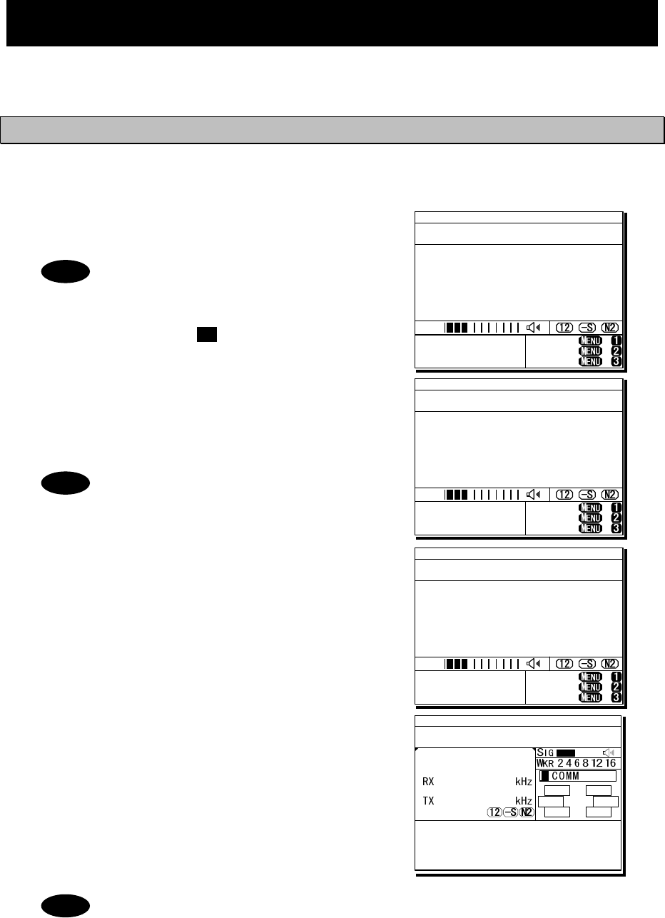
Operation
4-25
4.3 Setting the radio
This section describes how to set the communication frequencies and how to use the receiver
and transceiver functions.
4.3.1 Setting the communication frequencies
Use the free frequency input mode to input the communication frequencies directly.
■ Procedure ■
1
1
1.
.
.
In the status display, use the numeric keypad
to input the frequency.
- When 1 is input using the numeric
keypad, it appears on the far right as
shown in the screen on the right.
- In the user/ITU channel input mode,
press the CH key once or twice to
hide the channel display.
2
2
2.
.
.
Input numbers to the 0.1 kHz place and
press ENT.
The transmission frequency input mode opens as
shown in the screen at right.
For a simplex frequency, press ENT to
automatically input the same frequency
as the receiving frequency to complete
communication frequency settings.
3
3
3.
.
.
Input the transmission frequency in the
same way as the reception frequency.
4
4
4.
.
.
Input numbers to the 0.1 kHz place and
press ENT.
The communication frequency settings are
complete and the screen shows the operating
display.
- Turning the jog dial on the status display changes the reception frequency on
the 0.1 kHz scale. For simplex frequencies, the transmission frequency is
changed at the same time.
- The above operation is also available on the transceiver setting screen of the
operating display.
- The above operation is unavailable in the telex mode. The telex frequency is
set with the menu of the data terminal, as Tune Î Tx/Rx frequency set.
Note
Note
Note
TEL -----.1
2331.5
RX kHz
TX kHz
NonDST: +
DROBOS: +
EdtDST: +
ID 431001234 23:59(UTC)
Pos 89゚59.0123'N
179゚59.6789'E@23:59 (EXT)
SIG
WKR scan bands:
2 4 6 8 12 16MHz
TEL
12345.0
-----.-
RX kHz
TX kHz
NonDST: +
DROBOS: +
EdtDST: +
ID 431001234 23:59(UTC)
Pos 89゚59.0123'N
179゚59.6789'E@23:59 (EXT)
SIG
WKR scan bands:
2 4 6 8 12 16MHz
TEL
12345.0
---12.3
RX kHz
TX kHz
NonDST: +
DROBOS: +
EdtDST: +
ID 431001234 23:59(UTC)
Pos 89゚59.0123'N
179゚59.6789'E@23:59 (EXT)
SIG
WKR scan bands:
2 4 6 8 12 16MHz
ID 431001234 23:59(UTC)
Pos 89゚59.0123'N
179゚59.6789'E@23:59 (EXT)
Communicating on
TEL Rx:12345.0/Tx:12345.0kHz
Tip)Use FUNC to change op area.
[HLD][END]
AA
TEL
12345.0
12345.0
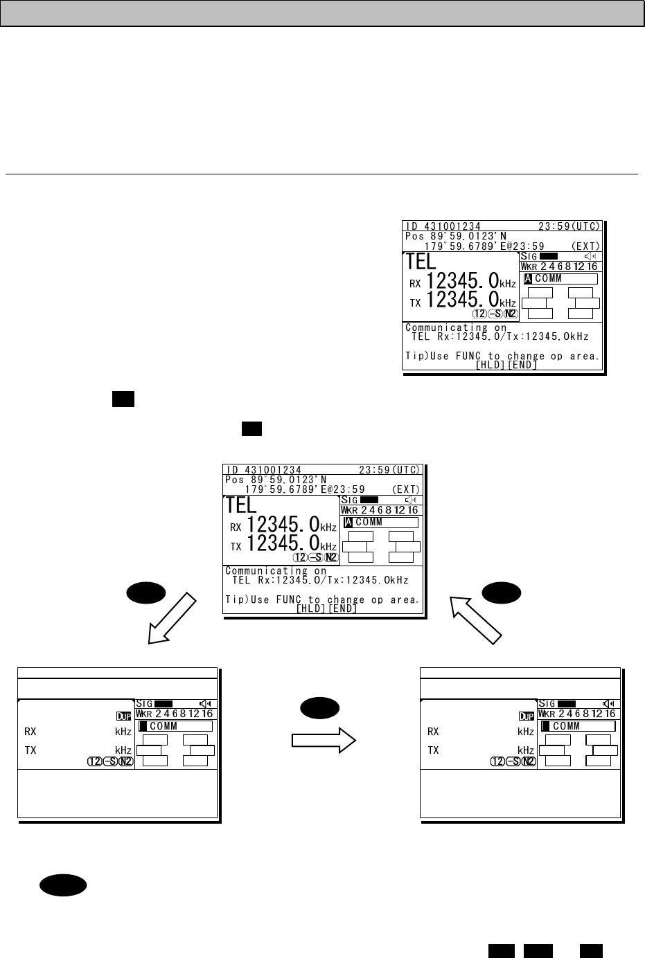
Operation
4-26
4.3.2 Setting the communication channels
Besides the free frequencies described previously, ITU channel mode and user channel modes
can also be set. The ITU channel mode is mode for using channels based on the international
standard and is built-in to the equipment. The user channel mode is the mode for using channels
on pre-registered frequencies. These modes can be used according to the operations.
(1) Selecting a frequency and channel input mode
■ Procedure ■
1
1
1.
.
.
Set the screen of the status display or the
operating display.
The operating display at right shows free frequency
mode.
2
2
2.
.
.
Press the CH key.
As shown below, each time the CH key is pressed the mode changes in order from the free
frequency mode, ITU channel mode, to the user channel mode.
(Free frequency input mode)
(ITU channel mode) (User channel mode)
- If changed to the ITU channel mode, the communication mode of the free
frequency input mode and the previous (or lowest) ITU channel number are
applied.
- The above operation is unavailable in the telex mode.
- If the communication mode is changed by pressing the TEL, DSC, or CW keys,
the free frequency input mode is set.
Note
CHCH
CH
ID 431001234 23:59(UTC)
Pos 89゚59.0123'N
179゚59.6789'E@23:59 (EXT)
Communicating on
TEL Rx: 4360.0/Tx: 4068.0kHz
Tip)Use FUNC to change op area.
[HLD][END]
AA
TEL
4360.0
4068.0
ITU- 402
ID 431001234 23:59(UTC)
Pos 89゚59.0123'N
179゚59.6789'E@23:59 (EXT)
Communicating on
TEL Rx: 4357.0/Tx: 4065.0kHz
Tip)Use FUNC to change op area.
[HLD][END]
AA
TEL
4357.0
4065.0
U01- 001
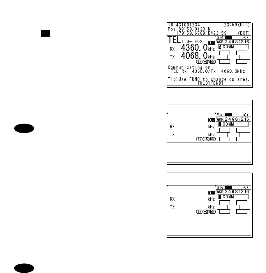
Operation
4-27
(2) Setting the ITU channels
■ Procedure ■
1
1
1.
.
.
After setting the TEL, DSC or CW modes,
press the CH key to set the display to the
ITU channel mode.
2
2
2.
.
.
Input the channel by using the numeric
keypad.
When 4 is input using the numeric
keypad, it appears on the far right
as shown in the screen on the right.
3
3
3.
.
.
Input the rest of the digits and press ENT.
The input ITU channel frequency is displayed
and the settings are complete.
- See the appendix "11.4 ITU channel list (TEL/CW/TLX)" for a list of
pre-installed ITU channels and their frequencies.
- Besides doing settings with the numeric keypad, settings can also be done with
the jog dial.
- For DSC mode, normally perform the above procedure to receive the routine
message. Furthermore, when sending a DSC message, the calling frequency is
set via the menu automatically and the above procedure is not needed.
- The above operation is unavailable in the telex mode. The ITU channel in the
telex mode is set with the controller menu 5.2 ITU channel list, or the data
terminal menu operation, as Tune Î ITU channel set.
Note
Note
ID 431001234 23:59(UTC)
Pos 89゚59.0123'N
179゚59.6789'E@23:59 (EXT)
Communicating on
TEL Rx: 4360.0/Tx: 4068.0kHz
Tip)Use FUNC to change op area.
[HLD][END]
AA
TEL
4360.0
4068.0
ITU- 4
ID 431001234 23:59(UTC)
Pos 89゚59.0123'N
179゚59.6789'E@23:59 (EXT)
Communicating on
TEL Rx: 4357.0/Tx: 4065.0kHz
Tip)Use FUNC to change op area.
[HLD][END]
AA
TEL
4357.0
4065.0
ITU- 401
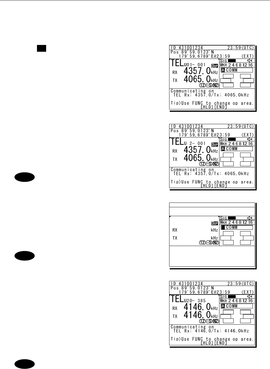
Operation
4-28
(3) Setting user channels
A total of 20 groups with 20 channels set to each group (i.e. 400 channels) can be registered on
the equipment. This section explains how to set channels that are already registered.
■ Procedure ■
1
1
1.
.
.
Use the CH key to set the display to the user
channel mode status display.
2
2
2.
.
.
Pressing ENT causes the channel group
number to blink so a channel group can be
input.
Use the numeric keypad or jog dial to input the
number of a registered group.
When 2 is input using the numeric
keypad, it appears on the far right
as shown in the screen on the right.
3
3
3.
.
.
After inputting a group number, pressing ENT
causes the channel number to blink so a user
channel can be input.
Use the numeric keypad or jog dial to input the
number of a registered channel.
When 3 is input using the numeric
keypad, it appears on the far right
as shown in the screen on the right.
4
4
4.
.
.
Input the rest of the digits and press ENT.
¾ The input user channel frequency is
displayed and the settings are complete.
¾ The group name is displayed for 3 seconds
after the settings are done.
- Channels can be set directly in the status display or the operating display by
using the numeric keypad or the jog dial without setting a channel group. After
inputting with the numeric keypad, press ENT.
- See "5.4 Registering user channels" for how to register frequencies to user
channels.
- The user channel of the telex mode is set with the menu of the data terminal,
as Tune Î Frequency list.
Note
Note
Note
ID 431001234 23:59(UTC)
Pos 89゚59.0123'N
179゚59.6789'E@23:59 (EXT)
Communicating on
TEL Rx: 4357.0/Tx: 4065.0kHz
Tip)Use FUNC to change op area.
[HLD][END]
AA
TEL
4357.0
4065.0
U20- 3
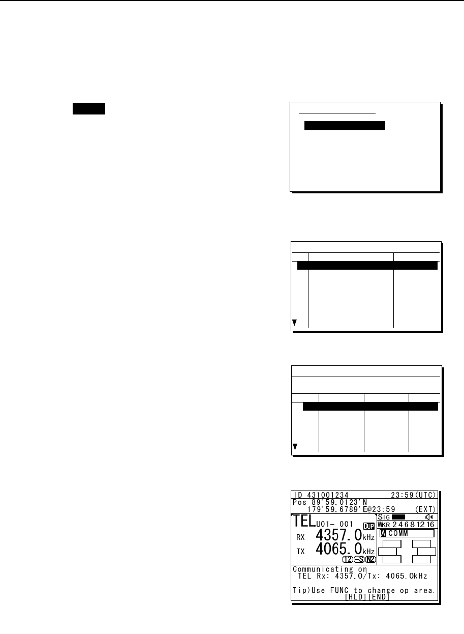
Operation
4-29
(4) Using channel lists
Besides the procedure above, user channels (except the telex mode) and ITU channels can also
be set from the channel lists (5.1 User channel list or 5.2 ITU channel list). This section explains
how to set channels that are already registered from the user channel list.
■ Procedure ■
1
1
1.
.
.
Press the MENU key, and through
hierarchical menus, select 5. Radio
operation.
2
2
2.
.
.
Select 1. User channel list and press ENT.
The user channel list index (group list) as
shown at right is displayed.
3
3
3.
.
.
Select the intended channel group and press
ENT.
The user channel list as shown at right is
displayed.
4
4
4.
.
.
Select the channel to set and press ENT.
The user channel settings are complete, the
status display is displayed.
5) Radio operation
1.User channel list
2.ITU channel list
3.Mode :TEL
4.Receiver
5.Transmitter
0.Back
5.1)User channel list (index)
No CH group name Type
01 JRC Tokyo TEL
02
03
04
05
06
07
08
Pacific ABC CW
5.1)User channel list (table)
Name: JRC Tokyo
Type: TEL
CHNo Rx[kHz] Tx[kHz] Mode
001 4357.0 4065.0 TEL
002
003
004
005
006
4360.0
4363.0
4366.0
4369.0
4372.0
4068.0
4071.0
4074.0
4077.0
4080.0
TEL
TEL
TEL
TEL
TEL
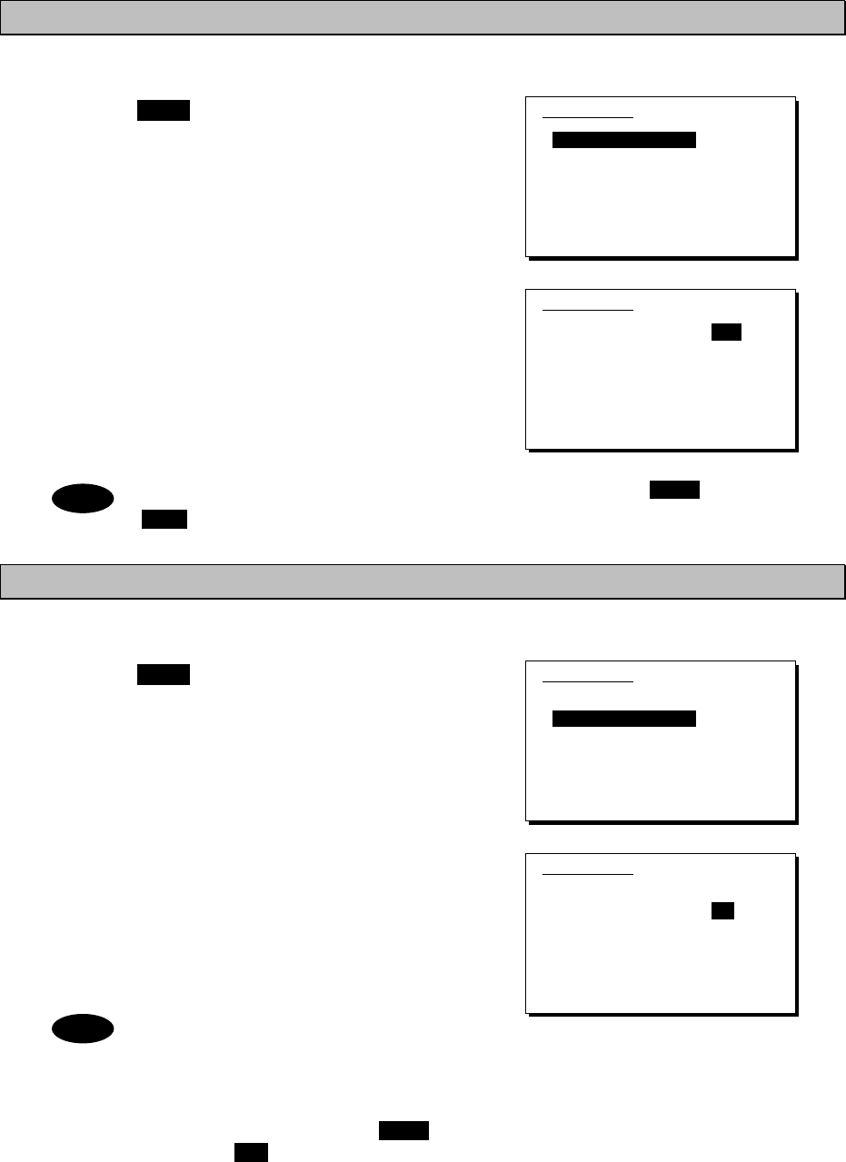
Operation
4-30
4.3.3 Setting the automatic gain control (AGC)
■ Procedure ■
1
1
1.
.
.
Press the MENU key, and through
hierarchical menus, select 5.4 Receiver.
2
2
2.
.
.
Select 1. Auto gain control and press ENT,
when the cursor moves to the right use the jog
dial to select Slow, Fast, or OFF.
After selecting and pressing ENT, the
settings are complete.
The same settings can be done by pressing and holding the FUNC key and the
5AGC key at the same time.
4.3.4 Setting the noise reduction (NR)
■ Procedure ■
1
1
1.
.
.
Press the MENU key, and through
hierarchical menus, after 5.4 Receiver
appears, move the cursor to 2. Noise
reduction.
2
2
2.
.
.
Press ENT to move the cursor to the right,
then use the jog dial to select NR1, NR2,
BC, or OFF.
After selecting and pressing ENT, the
settings are complete.
- The various settings are shown below.
・NR1: Noise reduction (low)
・NR2: Noise reduction (high)
・BC: Beat canceller
- The same settings can be done by
pressing and holding the FUNC key
and the 3NR key at the same time.
- This function is invalid in DSC mode or
telex mode. Moreover, the beat
canceller becomes invalid in CW mode.
5.4)Receiver
1.Auto gain control :Slow
2.Noise reduction :OFF
3.Attenuation :OFF
4.Clarifier :+000Hz
5.Squelch :OFF
6.CW bandwidth :Narrow
7.Scan
0.Back
5.4)Receiver
1.Auto gain control :Fast
2.Noise reduction :OFF
3.Attenuation :OFF
4.Clarifier :+000Hz
5.Squelch :OFF
6.CW bandwidth :Narrow
7.Scan
0.Back
5.4)Receiver
1.Auto gain control :Slow
2.Noise reduction :OFF
3.Attenuation :OFF
4.Clarifier :+000Hz
5.Squelch :OFF
6.CW bandwidth :Narrow
7.Scan
0.Back
5.4)Receiver
1.Auto gain control :Slow
2.Noise reduction :NR1
3.Attenuation :OFF
4.Clarifier :+000Hz
5.Squelch :OFF
6.CW bandwidth :Narrow
7.Scan
0.Back
Note
Note
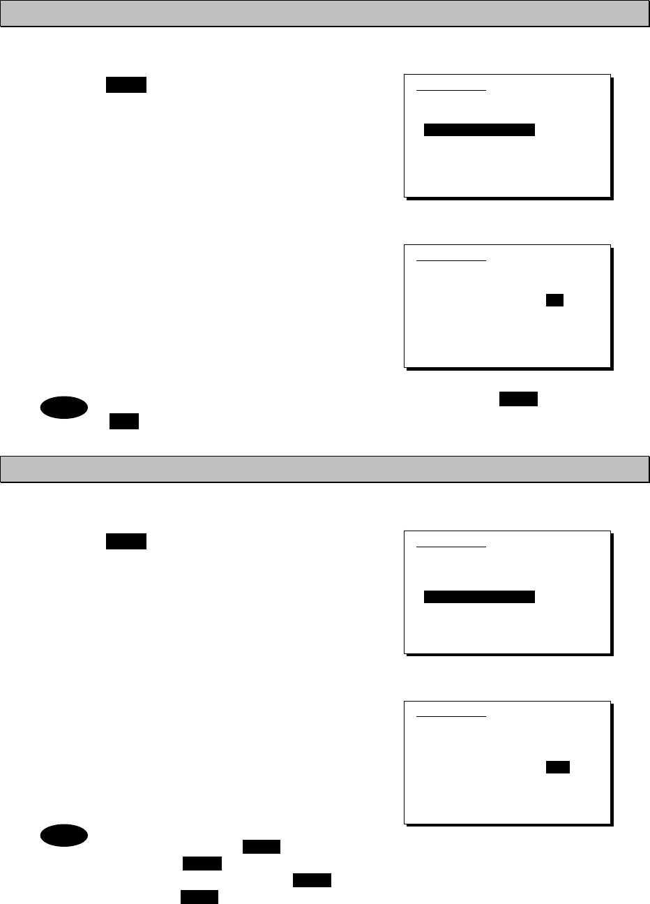
Operation
4-31
4.3.5 Setting the attenuation (ATT)
■ Procedure ■
1
1
1.
.
.
Press the MENU key, and through
hierarchical menus, after 5.4 Receiver
appears, move the cursor to 3.
Attenuation.
2
2
2.
.
.
Press ENT to move the cursor to the right,
then use the jog dial to select 6dB, 12dB,
18dB, or OFF.
After selecting and pressing ENT, the
settings are complete.
The same settings can be done by pressing and holding the FUNC key and the
4ATT key at the same time.
4.3.6 Setting the clarifier
■ Procedure ■
1
1
1.
.
.
Press the MENU key, and through
hierarchical menus, after 5.4 Receiver
appears, move the cursor to 4. Clarifier.
2
2
2.
.
.
Press ENT to move the cursor to the right, then
use the jog dial or numeric keypad to select a
value in the range of -200 to +200 Hz.
After inputting and pressing ENT, the settings
are complete.
- When using the numeric keypad,
input "+" with the 1CLAR key and "-"
with the 2SCAN key.
- Pressing and holding the FUNC key
and the 1CLAR key at the same time
opens a popup screen. The same
settings can be done here.
- This function is invalid in the DSC
mode or the telex mode.
5.4)Receiver
1.Auto gain control :Slow
2.Noise reduction :OFF
3.Attenuation :OFF
4.Clarifier :+000Hz
5.Squelch :OFF
6.CW bandwidth :Narrow
7.Scan
0.Back
5.4)Receiver
1.Auto gain control :Slow
2.Noise reduction :OFF
3.Attenuation :6dB
4.Clarifier :+000Hz
5.Squelch :OFF
6.CW bandwidth :Narrow
7.Scan
0.Back
5.4)Receiver
1.Auto gain control :Slow
2.Noise reduction :OFF
3.Attenuation :OFF
4.Clarifier :+000Hz
5.Squelch :OFF
6.CW bandwidth :Narrow
7.Scan
0.Back
5.4)Receiver
1.Auto gain control :Slow
2.Noise reduction :OFF
3.Attenuation :OFF
4.Clarifier :+008Hz
5.Squelch :OFF
6.CW bandwidth :Narrow
7.Scan
0.Back
Note
Note
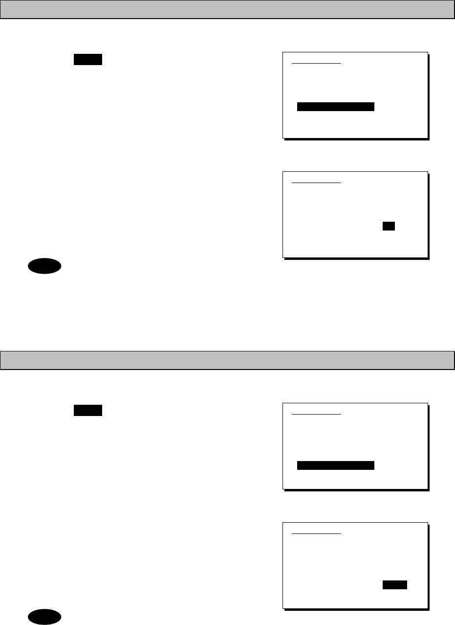
Operation
4-32
4.3.7 Setting the squelch level
■ Procedure ■
1
1
1.
.
.
Press the MENU key, and through
hierarchical menus, after 5.4 Receiver
appears, move the cursor to 5. Squelch.
2
2
2.
.
.
Press ENT to move the cursor to the right,
then use the jog dial or numeric keypad to
input a value in the range of 000 to 100.
After inputting and pressing ENT, the settings
are complete.
- Setting the value to 000 automatically
displays it as OFF.
- This function is invalid in the DSC
mode or the telex mode.
4.3.8 Setting the CW bandwidth
■ Procedure ■
1
1
1.
.
.
Press the MENU key, and through
hierarchical menus, after 5.4 Receiver
appears, move the cursor to 6. CW
bandwidth.
2
2
2.
.
.
Press ENT to move the cursor to the right,
then use the jog dial to select Wide or
Narrow.
After inputting and pressing ENT, the settings
are complete.
This function is enabled in CW mode
only.
5.4)Receiver
1.Auto gain control :Slow
2.Noise reduction :OFF
3.Attenuation :OFF
4.Clarifier :+000Hz
5.Squelch :OFF
6.CW bandwidth :Narrow
7.Scan
0.Back
5.4)Receiver
1.Auto gain control :Slow
2.Noise reduction :OFF
3.Attenuation :OFF
4.Clarifier :+000Hz
5.Squelch :012
6.CW bandwidth :Narrow
7.Scan
0.Back
Note
5.4)Receiver
1.Auto gain control :Slow
2.Noise reduction :OFF
3.Attenuation :OFF
4.Clarifier :+000Hz
5.Squelch :OFF
6.CW bandwidth :Narrow
7.Scan
0.Back
5.4)Receiver
1.Auto gain control :Slow
2.Noise reduction :OFF
3.Attenuation :OFF
4.Clarifier :+000Hz
5.Squelch :OFF
6.CW bandwidth :Narrow
7.Scan
0.Back
Note
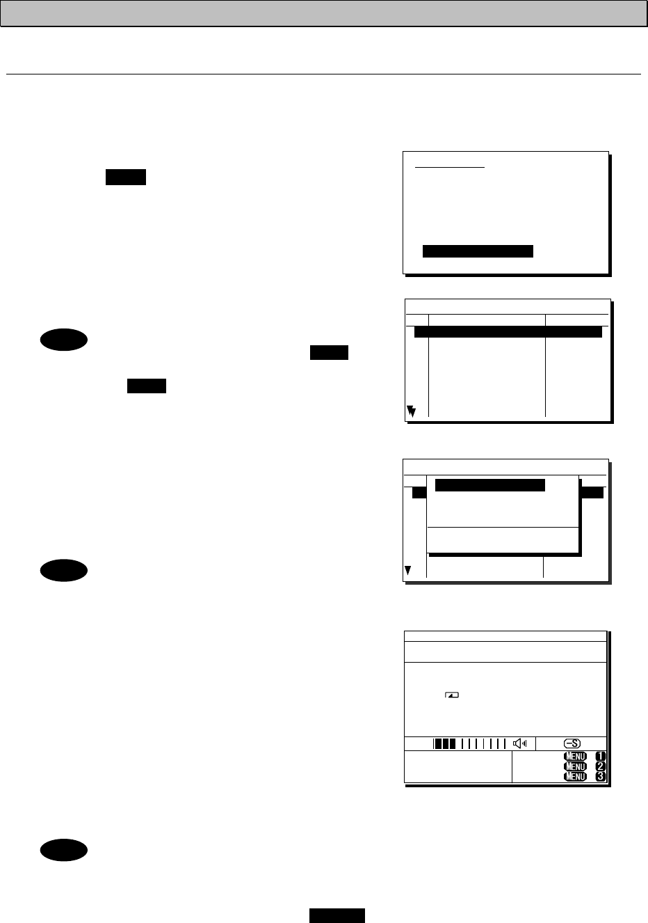
Operation
4-33
4.3.9 Scanning the Rx frequencies
(1) Scanning of channels in TEL/DSC/CW mode
The scanning of channels in the TEL/DSC/CW mode is started with the controller.
■ Procedure ■
1
1
1.
.
.
Press the MENU key, and through
hierarchical menus, after 5.4 Receiver
appears, move the cursor to 7. Scan.
2
2
2.
.
.
Press ENT to confirm the selection.
The group list as shown at right is displayed.
- The previous scan can be restarted
by pressing and holding the FUNC
key and then pressing the
2SCAN key on the status display.
- If the user channel is not registered,
scan cannot be done so the screen
shown at right is not displayed.
3
3
3.
.
.
Select the channel group to scan with the
cursor and press ENT.
The popup screen as shown at right is
displayed.
If the popup screen shown at right
is displayed during scanning, Stop
appears instead of Execute.
4
4
4.
.
.
Select 1. Execute and press ENT, the screen
at right is displayed and scanning starts.
¾ To check the registered channels in the
channel group, select 2. User channel list
and press ENT.
¾ To change the scanning speed, select 3.
Scan speed (sec) and press ENT. The setting
range is 0.3 to 9.9 seconds, the same as
TEL/DSC/CW.
- Scanning can be done regardless of the squelch being set to open or close.
When pressing the PTT or keying the CW keyer, or when squelch is opened
after closing condition, scanning stops momentarily and the icon starts
blinking. In this case the scanning can be restarted by pressing ENT.
- To stop scanning, press the CANCEL key.
- When scanning to receive routine DSC calls, set the scan speed to 0.3
seconds within 6 channels.
Note: If too many channels are being scanned, it may not catch the reception.
5.4)Receiver
1.Auto gain control :Slow
2.Noise reduction :OFF
3.Attenuation :OFF
4.Clarifier :+000Hz
5.Squelch :OFF
6.CW bandwidth :Narrow
7.Scan
0.Back
5.4.7)Scan
No CH group name Type
01 JRC Tokyo TEL
02
03
04
05
06
07
08
Pacific ABC CW
5.4.7)Scan
No CH group name Type
01 JRC Tokyo TEL
02
03
04
05
06
07
08
Pacific ABC CW
1. Execute
2. User channel list
3. Scan speed (sec)
TEL DSC CW
3.0 0.3 3.0
Note
Note
Note
TEL
4357.0
-----.-
RX kHz
TX kHz
NonDST: +
DROBOS: +
EdtDST: +
ID 431001234 23:59(UTC)
Pos 89゚59.0123'N
179゚59.6789'E@23:59 (EXT)
SIG
WKR scan bands:
2 4 6 8 12 16MHz
JRC Tokyo
U01- 001
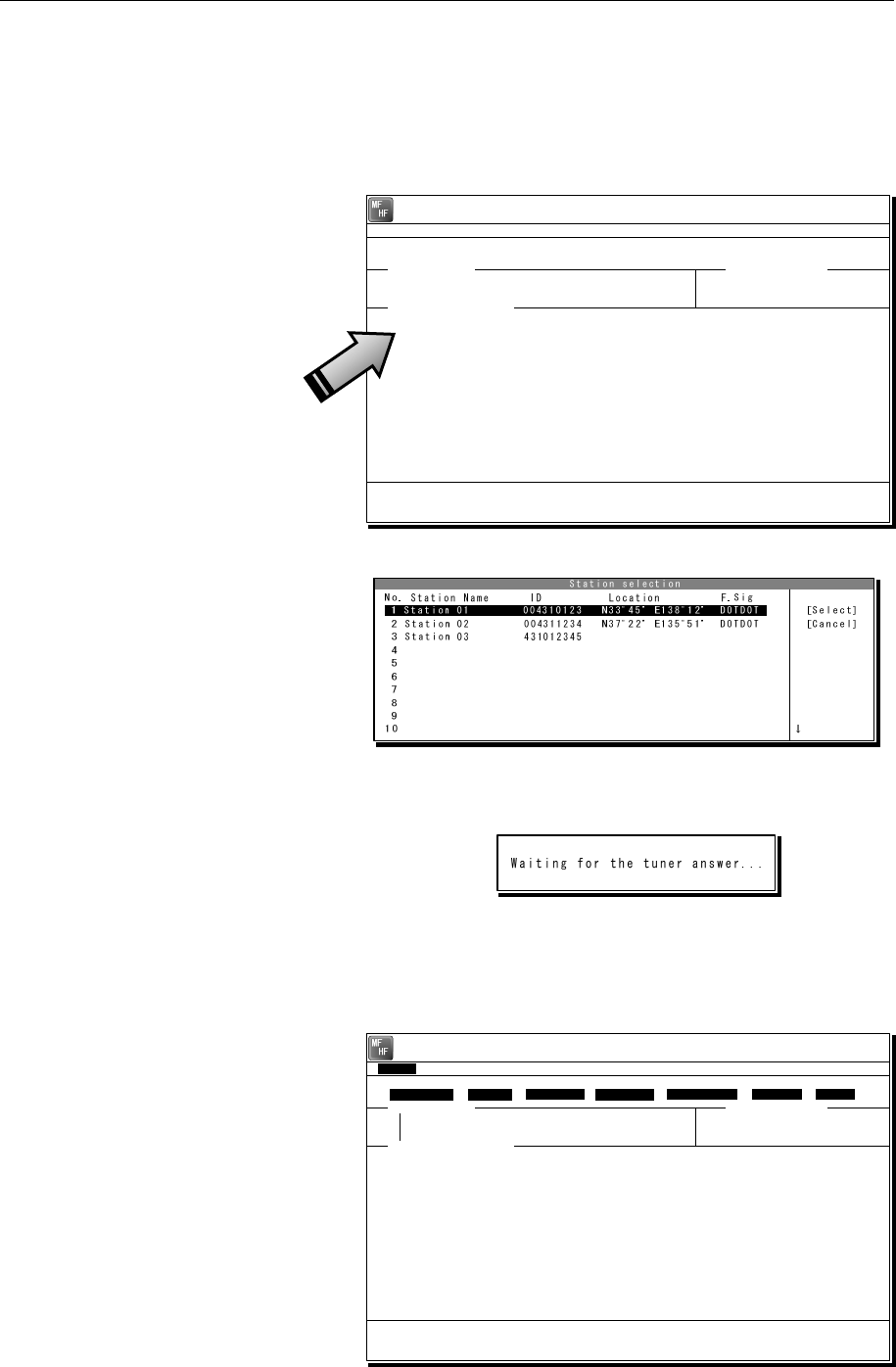
Operation
4-34
(2) Scanning of channels in telex mode
The scanning of channels in the telex mode is started with the data terminal.
■ Procedure ■
1
1
1.
.
.
If displaying the message of "Press Enter key to get the access right in the NBDP
mode…" on the data terminal, press Enter key on the keyboard.
The operation of the data
terminal becomes possible in
the telex mode, except when
the controller is used.
2
2
2.
.
.
On the main menu and the dropdown menu, select Tune Î Scanning start with Enter
key.
The registered station list is
displayed.
3
3
3.
.
.
Select the radio station having the channel group to be scanned with the cursor, and
press Enter key.
The antenna is tuned to the
every frequency registered in
the selected radio station. The
screen at right is displayed
while tuning the antenna.
4
4
4.
.
.
After completing the antenna tuning, scanning starts.
¾ The screen as shown at right
is displayed while scanning.
¾ When receiving a call by the
ARQ or FEC mode, scanning
stops and the communication
starts. After finishing the
communication, scanning
restarts automatically.
¾ The scanning speed can be
changed with the menu on the
regular screen, as System Î
Scan speed.
¾ When breaking the scanning,
select Tune Î Scanning stop.
[TEL] Tx= 2174.5kHz/Rx= 2174.5kHz USB
File Tune Connect Service System Help
STATUS INFO
[No scanning] TUNER :[READY]
Tx.POWER :[HIGH]
Press Enter key to get the access right in the NBDP mode...
Scanning info Tuner/Tx.POWER
Last status message
[TLX] Tx=-----.-kHz/Rx= 2174.5kHz USB
File Tune Connect Service System Help
STATUS INFO
ST-BY
No. Station:[Station 01 ] ID:[004310123] TUNER :[-----]
01 Location:[N33゚45'E138゚12'] F.Sig:[DOTDOT] Tx.POWER :[HIGH]
Move the cursor to the item you want with ↑, ↓, →, ← then press Enter.
File manager.
File
Free sig. ST-BY Calling Receive Rephasing Repeat Traf
Scanning info Tuner/Tx.POWER
Last status message
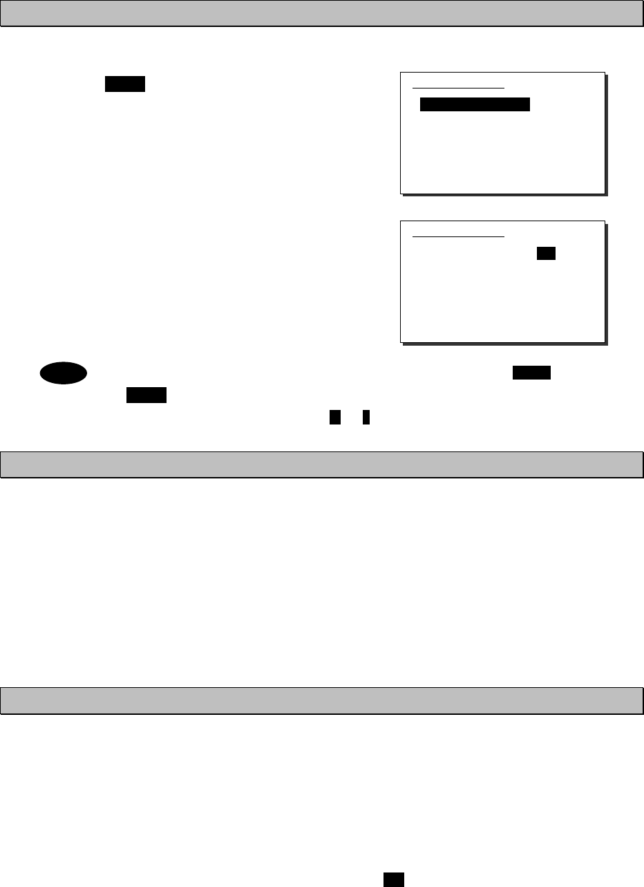
Operation
4-35
4.3.10 Reducing the Tx power
■ Procedure ■
1
1
1.
.
.
Press the MENU key, and through
hierarchical menus, select 5.5
Transmitter.
2
2
2.
.
.
Select 1. Power and press ENT to move
the cursor to the right, then use the jog dial
to select Medium or Low.
After selecting and pressing ENT, the
settings are complete.
- The same settings can be done by pressing and holding the FUNC key and the
9 key at the same time.
- When the Tx power is reduced, M or L is displayed on the screen.
4.3.11 Setting the antenna tuning power
■ Procedure ■
On the 5.5 Transmitter menu mentioned above, select the 2. Tune power and press ENT
to move the cursor to the right, then select a value from 0 to 3 with the jog dial.
¾ The antenna tune output grows larger by about 5W step.
¾ The factory default setting is 0 (Normal).
¾ After selecting and pressing ENT, the settings are complete.
4.3.12 Setting the Auto Tune Start (ATS) function
■ Procedure ■
On the 5.5 Transmitter menu mentioned above, select the 3. Auto tune start and press
ENT to move the cursor to the right, then set to ON or OFF with the jog dial.
¾ After setting to ON, when pressing the PTT key under the following condition in TEL mode,
the antenna tuner starts tuning automatically.
- When the Tx frequency is untuned, or
- when the PA power is not turned on, i.e. the ON is not displayed.
¾ This ATS setting data is saved in the controller. Therefore if two controllers are connected,
this function can be set to the controllers respectively.
Note
PWR
RDC
5.5)Transmitter
1.Power :High
2.Tune power :Normal
3.Auto tune start :ON
0.Back
5.5)Transmitter
1.Power :Low
2.Tune power :Normal
3.Auto tune start :ON
0.Back
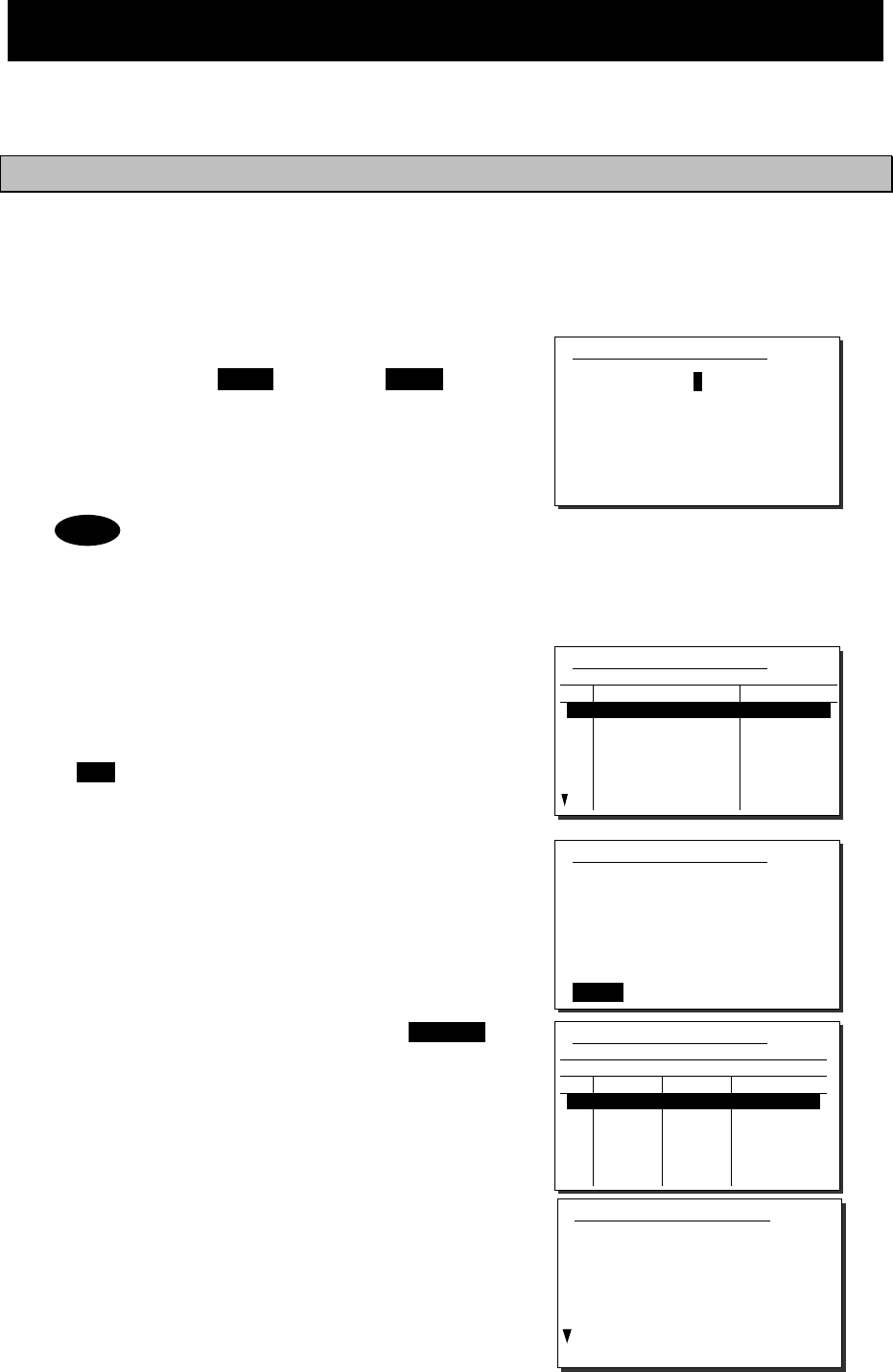
Operation
4-36
4.4 Basic DSC operations
When calling stations, the DSC is also available for a routine, safety, urgency call, or a distress
alert. This section describes basics of how to use the DSC to make routine calls.
4.4.1 Routine calls to an individual station
For radiotelephone or telex communication, a DSC routine call to the station to be called can be
made as follows.
■ Procedure ■
1
1
1.
.
.
On the status display or operation display,
holding down the MENU key, press 1CLAR key
to open “1. DSC non-distress call”.
The screen as shown at right is displayed. The
calling FRQ of 2177.0 kHz is the prescribed default
value. But the working FRQ (MF) is rewritable.
If no data is shown in the working FRQ field
just after turning on, please contact JRC or
our agency to register the nonvolatile data.
In this case, the input MF data is stored
temporarily as the volatile data.
2
2
2.
.
.
Input the destination address.
- If inputting the 9 digits MMSI manually, use
the numeric keypad or the jog dial, or
- If the DSC call list is already prepared, press
ENT to open the station list as shown at right
and select the receiver from the list.
3
3
3.
.
.
The cursor is focused on the Call. To make
a call without changing the parameters,
press ENT.
- To change the DSC calling frequency, select the
Calling FRQ and press ENT to open the DSC call
list as shown at right, if already prepared. But in
this case if inputting manually, press CANCEL
key to close the list and, input the proper DSC
frequencies in conformity with regulations.
- After changing the DSC calling frequency on HF,
the working frequency is automatically selected
within upto 10 seconds. However if no frequency
is detected or if another frequency is needed,
manually inputting the frequency is also
available.
- To check the details of the message, press
ENT on the Preview menu to open the screen
as shown at right (bottom).
1)DSC non-distress call
Call type :[RTN/Indv/TEL ]
Address :[ ]
Calling FRQ:[ 2177.0kHz]
Working FRQ:[ 2150.0kHz]
[Call] [Preview] [Cancel]
1)DSC non-distress call
Call type :[RTN/Indv/TEL ]
No Station name MMSI
01
02
03
04
05
06
07
JRC MITAKA1
JRC MITAKA2
JRC MITAKA3
JRC MITAKA4
JRC MITAKA5
JRC MITAKA6
JRC MITAKA7
123456789
431012345
431123456
431234567
431000123
004310014
431888888
1)DSC non-distress call
Call type :[RTN/Indv/TEL ]
Address :[123456789]
Calling FRQ:[ 2177.0kHz]
Working FRQ:[ 2150.0kHz]
[Call] [Preview] [Cancel]
1)DSC non-distress call
Format :Individual
Address :123456789
Category :Routine
Self-ID :431001234
Telecommand1:Radiotelephone
Telecommand2:No information
Working FRQ :Tx 2150.0kHz
Rx 2150.0kHz
[Call] [Return] [Cancel]
1)DSC non-distress call
Call type :[RTN/Indv/TEL ]
JRC MITAKA1 123456789
No RX[kHz] TX[kHz] Category
01
02
03
04
05
06
2177.0
4208.0
4208.5
4209.0
6313.0
6313.5
2177.0
4208.0
4208.5
4209.0
6313.0
6313.5
RTN
RTN
RTN
RTN
RTN
RTN
Note
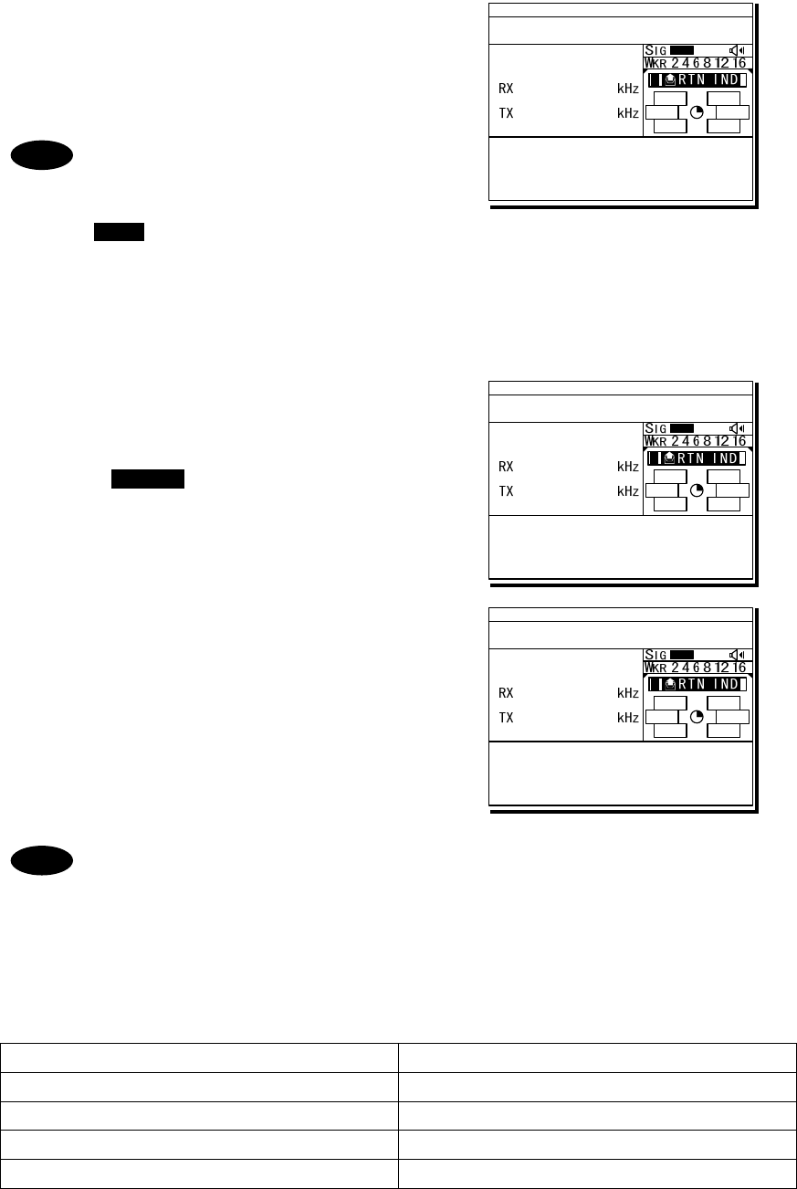
Operation
4-37
4
4
4.
.
.
The operating display is appeared and
initiates the DSC call.
After checking the channel free condition, sends
the message and waits for the acknowledgement.
During waiting for the acknowledgement,
the handling menus are available for
the following purposes.
Note) To focus the cursor on it, use
FUNC key to move the active screen
area.
- RTRY ... Resends the message.
- INF ...... Indicates the message contents.
- HLD ..... Makes the event on hold.
- END .... Terminates the event.
5
5
5.
.
.
When receiving the acknowledgement
the ALM lamp starts blinking, and the
receiving alarm gradually grows louder.
¾ Pressing CANCEL key or ENT silences the
alarm.
¾ The radiotelephone frequency is set and the
antenna is tuned automatically.
6
6
6.
.
.
When requested the radiotelephone
communication, start the communication
with the handset.
- After completing the routine individual call where the ARQ or FEC is specified,
the telex mode is set to the equipment. Then the telex communication can be
started with the data terminal.
- If the MMSI of the coast station is input at Address, the working frequency is
specified by the coast station. Thus the Working FRQ line is disappeared.
- If the receiver is unable to comply with the call, own station may receive one of
the following acknowledgements. (* are coast stations only) In this case, wait
and retry the call again later, if possible, according to the message.
No reason/ No reason given No operator/ No operator available
Congestion/ Congestion at maritime switching centre * Temp no operator/ Operator temporarily unavailable
Busy/ Busy EQP disabled/ Equipment disabled
Queue/ Queue indication
Unable FRQ/ Unable to use proposed channel
Barred/ Station barred
Unable mode/ Unable to use proposed channel
Note
DSC
2177.0
2177.0
ID 431001234 23:59(UTC)
Pos 89゚59.0123'N
179゚59.6789'E@23:59 (EXT)
TxTO:123456789|IND|RTN
Waiting for CH free
Call-F:Rx 2177.0/Tx 2177.0kHz
TEL :Rx 2150.0/Rx 2150.0kHz
[RTRY][INF][HLD][END]
A A
DSC
2177.0
2177.0
ID 431001234 23:59(UTC)
Pos 89゚59.0123'N
179゚59.6789'E@23:59 (EXT)
RxID:123456789|IND|RTN|ACK
Acknowledged(00.2min)
Rx FRQ: 2177.0kHz
TEL :Rx 2150.0/Tx 2150.0kHz
Press CANCEL to silence alarm.
A A
TEL
2150.0
2150.0
ID 431001234 23:59(UTC)
Pos 89゚59.0123'N
179゚59.6789'E@23:59 (EXT)
RxID:123456789|IND|RTN|ACK
Ready to talk(00.2min)
RX FRQ: 2177.0kHz
TEL :Rx 2150.0/Tx 2150.0kHz
[INF][HLD][END]
A A
Note
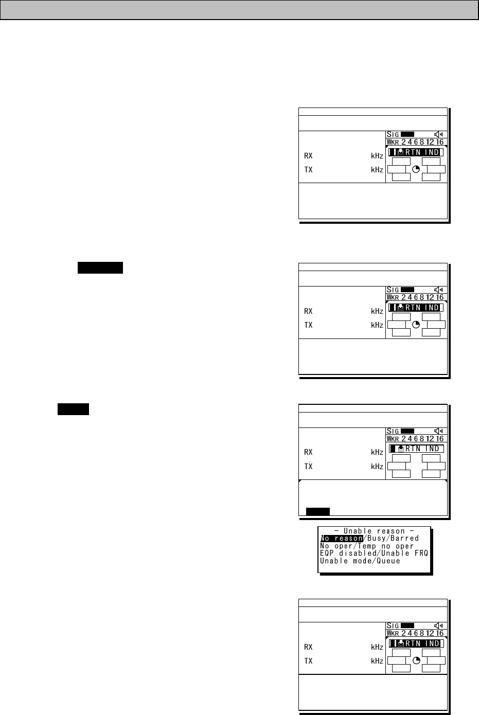
Operation
4-38
4.4.2 Receiving routine individual calls
When receiving an individual DSC call from a coast or ship station, according to the message,
perform the following procedures as appropriate.
■ Procedure ■
1
1
1.
.
.
The screen at right is displayed, and the
ALM lamp blinks and the alarm grows
louder gradually.
¾ The example message contains the following
information.
- Message type: Routine individual call
- Caller's MMSI: 123456789
¾ If no procedure exists, starts operating the
received message automatically.
2
2
2.
.
.
Press the CANCEL key or ENT to stop the
alarm, then the screen at right is displayed.
3
3
3.
.
.
Press FUNC key or ENT to move the focused
screen to the operation control screen and
select the option to handle the procedure.
Options shown at right are as follows.
ACK ....... Sends the acknowledgement.
NCK Sends a reply as “unable to comply”.
Note) Select the unable reason on the
popup screen at right.
NEW ...... Sends acknowledgement with a new channel.
INF ........ Indicates the receiving message.
HLD ....... Makes the procedure on hold.
END ...... Terminates the procedure.
4
4
4.
.
.
When sending the acknowledgement for
communication, select ACK and press ENT.
¾ Instead of selecting ACK, lifting the handset
from the cradle is also available.
¾ The equipment waits for the channel free
condition as shown at right. After checking it,
the acknowledgement is sent immediately.
ID 431001234 23:59(UTC)
Pos 89゚59.0123'N
179゚59.6789'E@23:59 (EXT)
RxID:123456789|IND|RTN
Waiting to send ACK(00.3min)
RX FRQ: 2177.0kHz
TEL :Rx 2150.0/Tx 2150.0kHz
Press CANCEL to silence alarm.
DSC
2177.0
2177.0
A A
ID 431001234 23:59(UTC)
Pos 89゚59.0123'N
179゚59.6789'E@23:59 (EXT)
RxID:123456789|IND|RTN
Waiting to send ACK(00.3min)
RX FRQ: 2177.0kHz
TEL :Rx 2150.0/Tx 2150.0kHz
[ACK][NCK][NEW][INF][HLD][END]
DSC
2177.0
2177.0
A A
ID 431001234 23:59(UTC)
Pos 89゚59.0123'N
179゚59.6789'E@23:59 (EXT)
RxID:123456789|IND|RTN
Waiting to send ACK(00.3min)
RX FRQ: 2177.0kHz
TEL :Rx 2150.0/Tx 2150.0kHz
[ACK][NCK][NEW][INF][HLD][END]
DSC
2177.0
2177.0
[ACK]
A A
ID 431001234 23:59(UTC)
Pos 89゚59.0123'N
179゚59.6789'E@23:59 (EXT)
TxTO:123456789|IND|RTN|ACK
Waiting for CH free
Call-F:Rx 2177.0/Tx 2177.0kHz
TEL :Rx 2150.0/Tx 2150.0kHz
[RTRY][INF][HLD][END]
DSC
2177.0
2177.0
A A
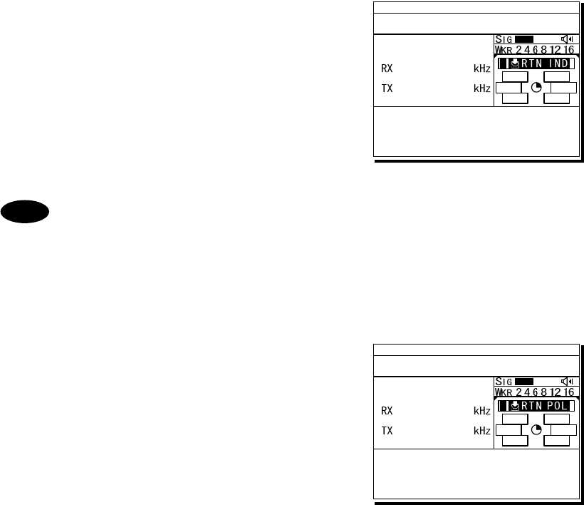
Operation
4-39
5
5
5.
.
.
After sending an acknowledgement, the
working frequency is set to communicate.
In TEL mode, start communicating using the
handset.
- After completing the DSC call sequence specifying the ARQ or FEC, the telex
mode is set to the equipment. Then the telex communication can be started
with the data terminal.
- If the receiving call is not the above mentioned call which requests TEL or
TLX communication but a polling call, the screen as follows is shown and, the
ALM lamp blinks and the alarm grows louder gradually. In this case, after
silencing the alarm, select ACK to acknowledge it.
Additionally note that if it is received while the 7.5.1.3 Polling call of the
Automatic ACK menu is set to ON, and there is no active procedure, this call
can be acknowledged automatically.
Note
ID 431001234 23:59(UTC)
Pos 89゚59.0123'N
179゚59.6789'E@23:59 (EXT)
TxTO:123456789|IND|RTN|ACK
Acknowledged(00.5min)
Call-F:Rx 2177.0/Tx 2177.0kHz
TEL :Rx 2150.0/Tx 2150.0kHz
[RTRY][INF][HLD][END]
TEL
2150.0
2150.0
A A
ID 431001234 23:59(UTC)
Pos 89゚59.0123'N
179゚59.6789'E@23:59 (EXT)
RxID:001234567|IND|RTN POLL
Waiting to send ACK(00.5min)
RX FRQ: 2177.0kHz
[ACK][INF][HLD][END]
DSC
2177.0
2189.5
A A
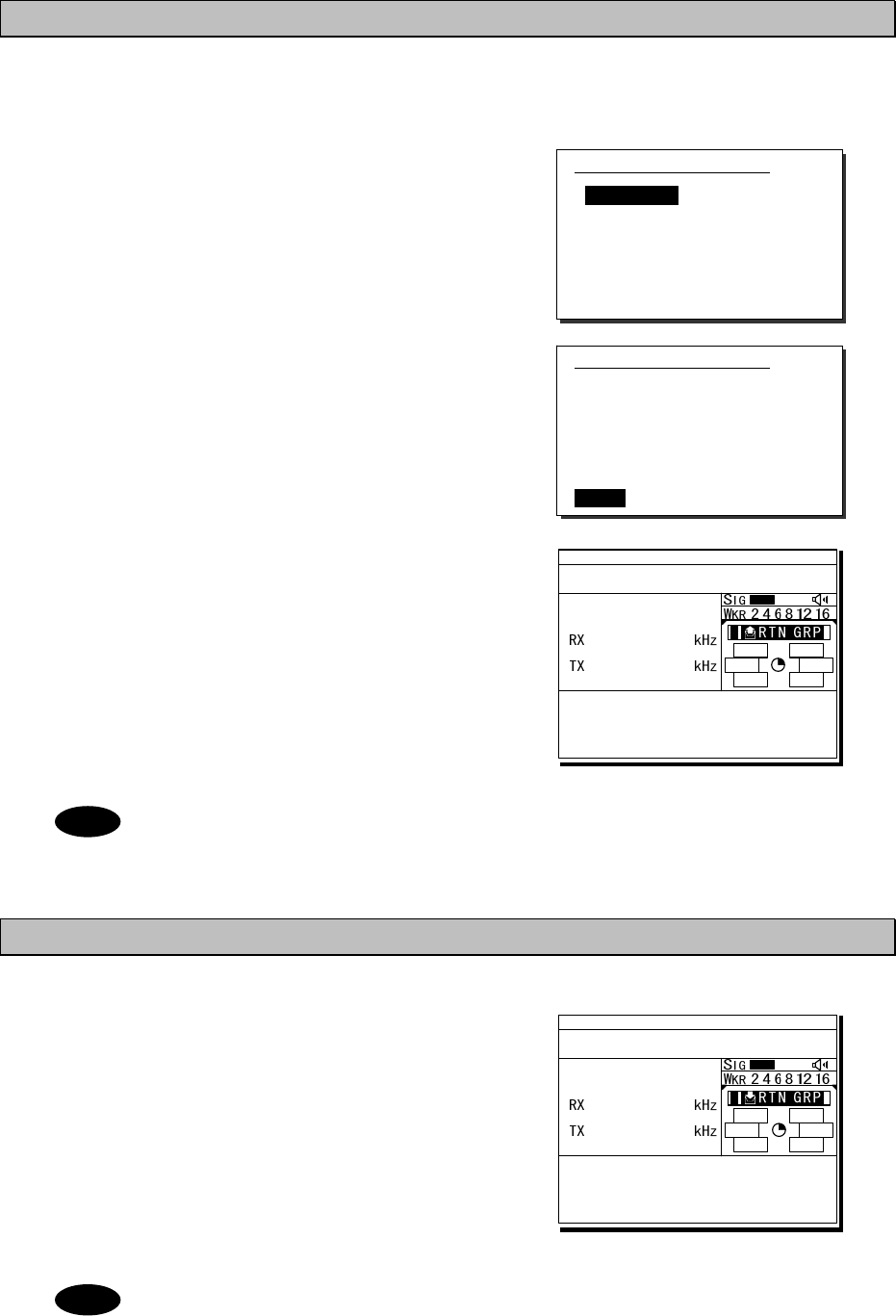
Operation
4-40
4.4.3 Routine group calls
For radiotelephone or FEC broadcasting, a DSC routine call to a group of ships is available.
■ Procedure ■
1
1
1.
.
.
On the menu “1. DSC non-distress call”
mentioned above, set the Call type on the
menu shown at right to RTN/Group/TEL or
RTN/Group/FEC.
2
2
2.
.
.
Input the Address, and frequency if required.
And then press ENT on the Call to start
sending the group call.
3
3
3.
.
.
After finishing the transmission, the working
frequency is set immediately.
In TEL mode, start broadcasting using the
handset.
After completing the group call where the FEC is specified, the telex mode is set
to the equipment. Then the telex communication can be started with the data
terminal.
4.4.4 Receiving routine group calls
■ Procedure ■
The screen at right is displayed, and the
ALM lamp blinks and the alarm grows louder
gradually.
If no procedure exists, starts operating the
received message, i.e. the specified working
frequency is set automatically. Then press
CANCEL to silence alarm and listen to the
broadcasting.
When receiving the group call where the FEC is specified, the telex mode is set to
the equipment. Then receive the telex broadcasting with the data terminal.
Note
1)DSC non-distress call
Call type :[RTN/Group/TEL ]
Address :[ ]
Calling FRQ:[ 2177.0kHz]
Working FRQ:[ 2150.0kHz]
[Call] [Preview] [Cancel]
Note
1)DSC non-distress call
Call type :[RTN/Group/TEL ]
Address :[012345678]
Calling FRQ:[ 2177.0kHz]
Working FRQ:[ 2150.0kHz]
[Call] [Preview] [Cancel]
ID 431001234 23:59(UTC)
Pos 89゚59.0123'N
179゚59.6789'E@23:59 (EXT)
TxTO:012345678|GRP|RTN
Ready for broadcast(00.5min)
Call-F:Rx 2177.0/Tx 2177.0kHz
TEL :Rx -----.-/Tx 2150.0kHz
[RTRY][INF][HLD][END]
TEL
2150.0
2150.0
A A
ID 431001234 23:59(UTC)
Pos 89゚59.0123'N
179゚59.6789'E@23:59 (EXT)
RxID:123456789|GRP|RTN
Ready for listening(00.5min)
RX FRQ: 2177.0kHz
TEL :RX 2150.0/TX -----.-kHz
[INF][HLD][END]
TEL
2150.0
2150.0
A A
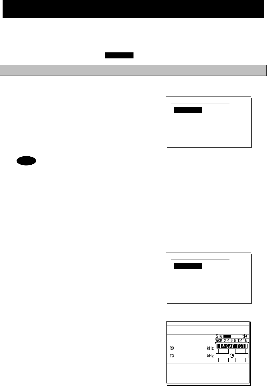
Operation
4-41
4.5 Emergency calls (DSC distress/urgency/safety calls)
In emergency, the DSC is available for distress, urgency, or safety calls. For safety and urgency
calls, either individual calls or area calls is selectable for the type of call. For distress alerts,
either sending after entering the nature of distress or frequency, or not entering anything is
available. In both cases, pressing the DISTRESS key is required to send the distress alert.
4.5.1 Safety or urgency calls to an individual station
■ Procedure ■
The procedure to send the safety or urgency
individual call is similar to the routine call except
selecting the call type to SAF/Indv/TEL or
URG/Indv/TEL (instead of TEL, ARQ or FEC also
available) and normally using the distress and
safety frequencies prior to other frequencies.
- Both calls of the safety test and the safety position request are described below.
- When calling a coast station with requesting the working frequency, input “0” in
the Tx and Rx frequency input field to send the own position data.
4
4.
.5
5.
.1
1.
.1
1
Special safety individual calls
(1) Safety test calls
■ Procedure ■
1
1
1.
.
.
Select SAF/Indv/Test in the Call type field
and input address.
Also change the Calling FRQ if needed.
2
2
2.
.
.
Press ENT on the Call to start sending
the safety test call.
After checking the channel free, the safety
test call is sent and the screen at right is
displayed.
1)DSC non-distress call
Call type :[SAF/Indv/TEL ]
Address :[ ]
Calling FRQ:[ 2187.5kHz]
Working FRQ:[ 2182.0kHz]
[Call] [Preview] [Cancel]
1)DSC non-distress call
Call type :[SAF/Indv/Test ]
Address :[ ]
Calling FRQ:[ 2187.5kHz]
[Call] [Preview] [Cancel]
Note
ID 431001234 23:59(UTC)
Pos 89゚59.0123'N
179゚59.6789'E@23:59 (EXT)
TxTO:123456789|IND|SAF Test
Waiting for ACK(00.2min)
Call-F:Rx 2187.5/Tx 2187.5kHz
[RTRY][INF][HLD][END]
DSC
2187.5
2187.5
A A
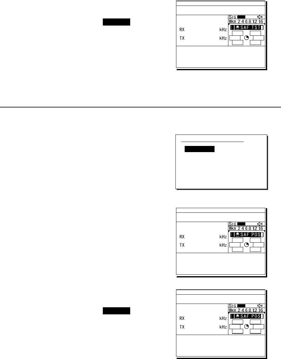
Operation
4-42
3
3
3.
.
.
When the acknowledgement is received,
the ALM lamp blinks and the alarm grows
louder. After silencing it with CANCEL key,
the screen becomes as shown at right.
The safety test call process is now complete.
However note that even though the call is sent
normally, the acknowledgement may not be
received from the called station for some reason.
(2) Safety position request calls
■ Procedure ■
1
1
1.
.
.
Select SAF/Indv/PosRQ in the Call type
field and input address.
Also change the Calling FRQ if needed.
2
2
2.
.
.
Press ENT on the Call to start sending
the safety position request call.
After checking the channel free, the safety
position request call is sent and the screen
at right is displayed.
3
3
3.
.
.
When the acknowledgement is received,
the ALM lamp blinks and the alarm grows
louder. After silencing it with CANCEL key,
the screen becomes as shown at right.
The position data of the station is indicated in
the Position field usually, and this procedure
is complete. However note that even though
the call is sent normally, the acknowledgement
may not be received from the called station for
some reason.
1)DSC non-distress call
Call type :[SAF/Indv/PosRQ]
Address :[ ]
Calling FRQ:[ 2187.5kHz]
[Call] [Preview] [Cancel]
ID 431001234 23:59(UTC)
Pos 89゚59.0123'N
179゚59.6789'E@23:59 (EXT)
RxID:123456789|IND|SAF Test|ACK
Acknowledged(00.2min)
RX FRQ: 2187.5kHz
[INF][HLD][END]
DSC
2187.5
2187.5
A A
ID 431001234 23:59(UTC)
Pos 89゚59.0123'N
179゚59.6789'E@23:59 (EXT)
TxTO:123456789|IND|SAF POS
Waiting for ACK(00.2min)
Call-F:Rx 2187.5/Tx 2187.5kHz
[RTRY][INF][HLD][END]
DSC
2187.5
2187.5
A A
ID 431001234 23:59(UTC)
Pos 89゚59.0123'N
179゚59.6789'E@23:59 (EXT)
RxID:123456789|IND|SAF POS|ACK
Acknowledged(00.2min)
RX FRQ: 2187.5kHz
Position:21゚28'N/157゚59'W
[INF][HLD][END]
DSC
2187.5
2187.5
A A
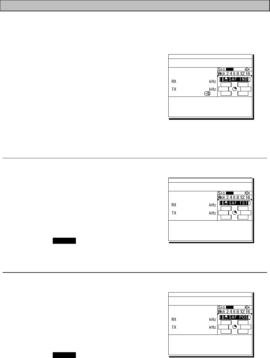
Operation
4-43
4.5.2 Receiving safety or urgency individual calls
When receiving an individual DSC call from a coast or ship station, according to the message,
perform the following procedures as appropriate.
■ Procedure ■
The screen at right is displayed, and the ALM
lamp blinks and the alarm grows louder gradually.
¾ If no procedure exists, starts operating the
received message automatically.
¾ Basically similar to the routine individual call
except normally using the distress and safety
frequencies prior to other frequencies.
4
4.
.5
5.
.2
2.
.1
1
Receiving special safety individual calls
(1) Safety test calls
■ Procedure ■
The screen at right is displayed, and the ALM
lamp blinks and the alarm grows louder gradually.
¾ If received while the 7.5.1.1 Test call of the
Automatic ACK menu is set to ON and there is
no active procedure, this call can be
acknowledged automatically.
¾ To acknowledge manually, after silencing the
alarm with CANCEL key, select ACK to start
sending procedure.
(2) Safety position request calls
■ Procedure ■
The screen at right is displayed, and the ALM
lamp blinks and the alarm grows louder gradually.
¾ If received while the 7.5.1.2 Position RQ call of
the Automatic ACK menu is set to ON and there
is no active procedure, this call can be
acknowledged automatically.
¾ To acknowledge manually, after silencing the
alarm with CANCEL key, select ACK to start
sending procedure.
¾ When sending a reply as “unable to comply”,
select NCK to send the acknowledge with no
position data.
ID 431001234 23:59(UTC)
Pos 89゚59.0123'N
179゚59.6789'E@23:59 (EXT)
RxID:123456789|IND|SAF
Waiting to send ACK(00.3min)
RX FRQ: 2187.5kHz
TEL :Rx 2182.0/Tx 2182.0kHz
Press CANCEL to silence alarm.
TEL
2182.0
2182.0
A A
ID 431001234 23:59(UTC)
Pos 89゚59.0123'N
179゚59.6789'E@23:59 (EXT)
RxID:123456789|IND|SAF Test
Waiting to send ACK(00.2min)
RX FRQ: 2187.5kHz
[ACK][INF][HLD][END]
DSC
2187.5
2187.5
A A
ID 431001234 23:59(UTC)
Pos 89゚59.0123'N
179゚59.6789'E@23:59 (EXT)
RxID:123456789|IND|SAF POS
Waiting to send ACK(00.2min)
RX FRQ: 2187.5kHz
[ACK][NCK][INF][HLD][END]
DSC
2187.5
2187.5
A A
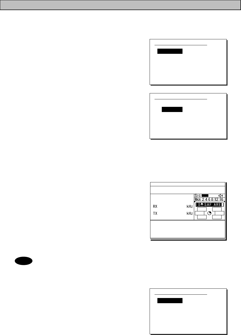
Operation
4-44
4.5.3 Safety or urgency area calls
For radiotelephone or FEC broadcasting, a DSC safety area call can be made as follows.
■ Procedure ■
1
1
1.
.
.
On the menu 1.DSC non-distress call, set the
Call type to SAF/Area/TEL or URG/Area/TEL
(instead of TEL, FEC also available).
The menu becomes as shown at right and
the cursor moves to the Area form.
2
2
2.
.
.
Set the area to call.
Input as below according to the Area form settings.
- When Center&rad
・ Enter the center point of the area in Center.
・ Enter the radius of the area in Radius.
- When Corner&dev (shown at right)
・ Enter the northwest corner of the area in
Corner.
・ Enter the south and north/east and west
deviation in a range from 00 to 99 in
Deviation.
3
3
3.
.
.
Select the Working FRQ/ Calling FRQ if
needed, then press ENT to start the area call.
4
4
4.
.
.
After finishing the transmission, start the
communication with the handset in TEL
mode.
- Incase of the urgency call, to inform receivers of the particular topic,
additional settings such as Medical TRNSP (medical transport ship) or Neutral
ship (neutral nationality) in the Subject field as shown at right are available.
However to use this function, it is needed to set the menu 7.5.4 Medical use or
7.5.5 Neutral use to ON once after powering on the equipment.
- After finishing the area call where the FEC is specified, the telex mode is set
to the equipment. Then start the telex communication with the data terminal.
Note
1)DSC non-distress call
Call type :[SAF/Area/TEL ]
Area form :[Center&rad]
- Center :[89゚N179゚E]
- Radius :[0500NM]
Calling FRQ:[ 2187.5kHz]
Working FRQ:[ 2182.0kHz]
[Call] [Preview] [Cancel]
1)DSC non-distress call
Call type :[SAF/Area/TEL ]
Area form :[Corner&dev]
- Corner :[ ゚N ゚E]
- Deviation:[ ゚/ ゚]
Calling FRQ:[ 2187.5kHz]
Working FRQ:[ 2182.0kHz]
[Call] [Preview] [Cancel]
1)DSC non-distress call
Call type :[URG/Area/TEL ]
Area form :[Center&rad]
- Center :[89゚N179゚E]
- Radius :[0500NM]
Subject :[No information]
Working FRQ:[ 2182.0kHz]
Calling FRQ:[ 2187.5kHz]
[Call] [Preview] [Cancel]
ID 431001234 23:59(UTC)
Pos 89゚59.0123'N
179゚59.6789'E@23:59 (EXT)
TxTO:Area|SAF
Waiting for CH free
Call-F:Rx 2187.5/Tx 2187.5kHz
TEL :Rx -----.-/Tx 2182.0kHz
[RTRY][INF][HLD][END]
DSC
2187.5
2187.5
A A
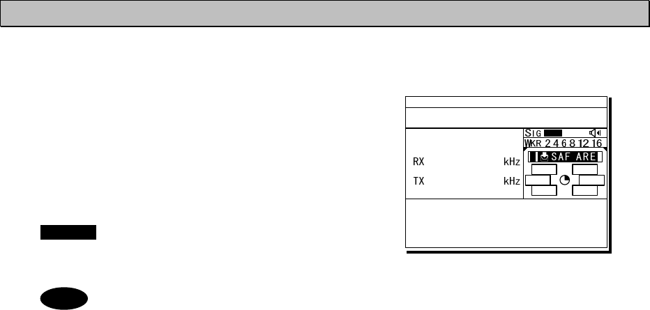
Operation
4-45
4.5.4 Receiving safety or urgency area calls
■ Procedure ■
The screen at right is displayed, and the
ALM lamp blinks and the alarm grows louder
gradually.
If no procedure exists, starts operating the
received message, i.e. the specified working
frequency is set automatically. Then press
CANCEL to silence alarm and listen to the
broadcasting.
- When receiving the area call where the FEC is specified, the telex mode is set
to the equipment. Then receive the telex broadcasting with the data terminal.
- To check the topic when receiving an urgency area call, select INF menu to
view the detail of the message.
Note
ID 431001234 23:59(UTC)
Pos 89゚59.0123'N
179゚59.6789'E@23:59 (EXT)
RxID:123456789|Area|SAF
Ready for listening(00.2min)
RX FRQ: 2187.5kHz
TEL :Rx 2182.0/Tx -----.-kHz
[INF][HLD][END]
TEL
2182.0
2182.0
A A
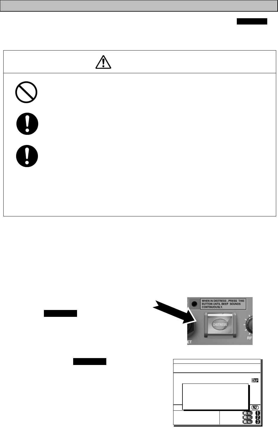
Operation
4-46
4.5.5 Distress alerts
When in distress, distress alerts are always transmitted by pressing the dedicated DISTRESS
key. The distress alerts transmit your own MMSI, ships position, time of the position, and the
nature of distress.
CAUTION
Do not test the distress alert.
Doing so may inconvenience local shipping and rescue centers.
When sending a distress alert, follow the instructions of the ship's captain
or officer in charge.
If a false distress alert is transmitted accidentally, select the Cancel menu
and transmit the distress cancel referring the guidance displayed on the
controller. And then report the false distress alert to a nearby RCC (Rescue
Coordination Center/ in Japan, inform the nearest Japan Coast Guard.)
Information to be reported:
Ship's name, type, nationality, and ID number, the date/time, location and
reason why the false distress alert was transmitted. Also the unit model name
and manufacture number/date, if possible.
4
4.
.5
5.
.5
5.
.1
1
Quick distress alerts
The following describes the procedure to send a distress alert immediately without using menus.
In this case, the nature of distress in the message will be sent as "Undesignated" by default.
Further, if no information for the position and the time of position obtained within 23.5 hours, this
information will be composed automatically.
■ Procedure ■
1
1
1.
.
.
Open the DISTRESS key cover.
2
2
2.
.
.
Press and hold the DISTRESS key for 4
seconds until the countdown is completed.
TEL ITU- 401
4357.0
4065.0
RX kHz
TX kHz
NonDST: +
DROBOS: +
EdtDST: +
ID 431001234 23:59(UTC)
Pos 89゚59.0123'N
179゚59.6789'E@23:59 (EXT)
SIG
WKR scan bands:
2 4 6 8 12 16MHz
Distress call starts
in sec
4
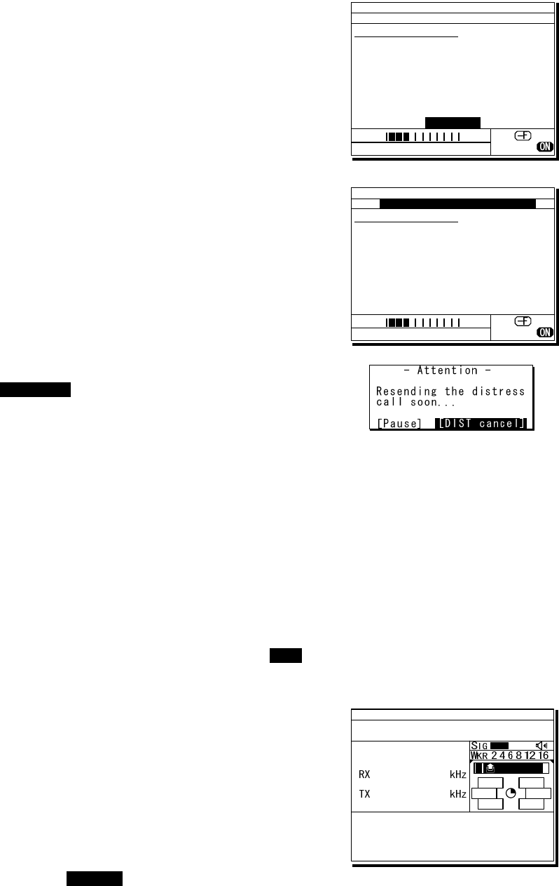
Operation
4-47
3
3
3.
.
.
After the antenna is tuned, the distress
alert is sent.
The distress alerts are sent on all 6 distress
and safety frequencies.
4
4
4.
.
.
The equipment stays in distress mode until
acknowledgement is received or the distress
alert cancelling procedure is complete.
¾ Unless an acknowledgement is received or the
distress alert is cancelled manually, the
distress alert repeats automatically in a
variable interval every 3.5 to 4.5 minutes.
(The time until next sending is shown at Next.)
¾ The distress alert can be sent manually while
waiting for acknowledgement by the
DISTRESS key operation mentioned above.
¾ While waiting for the acknowledgement, the
radiotelephone communication is available.
Additionally, when focusing the frequencies as
shown at right, the distress and safety
frequency can be changed with the jog dial.
¾ Pressing CANCEL key or ENT moves the
focused screen and makes following options
available.
FRQ ......... Moves the cursor to the frequency section
Pause ...... Makes the distress mode pause.
POS ......... Opens the position input menu
CHNG ...... Changes the distress alert type (Multi/Single mode and the frequencies)
Cancel ..... Starts the distress alert cancelling procedure, which is needed to send the DSC
acknowledgement and to broadcast in the radiotelephone mode from the “own ship”.
Furthermore, if the POS/CHNG is edited, MEM icon is displayed to indicate that there are
some data stored temporarily until resending the distress alert.
5
5
5.
.
.
When the acknowledgement is received, the
message is displayed as shown at the right.
¾ The ALM lamp starts blinking, and the receiving
alarm gradually grows louder.
¾ The radiotelephone mode is set to the
distress/safety frequency of the band on which
the acknowledgement is received and antenna
tuning is done immediately.
¾ Press the CANCEL key or ENT to silence the
alarm, then call for help with the handset.
Normally, the responding station calls on the
radiotelephone. Then reply to the receipt as
follows.
z Say, "MAYDAY".
z Say, "This is".
z Own ship's MMSI and call sign, position, nature of distress, and rescue requests
ID 431001234 23:59(UTC)
DSC Rx: 2187.5/Tx: 2187.5kHz
Distress calling
Next :---
Stage :Waiting for CH free
Call-F: / / / / /
Nature:Undesignated
PosUTC: 89゚59.0123'N
:179゚59.6789'E @23:59
Mode :Radiotelephone
[Cancel]
SIG
WKR 2 4 6 8 12 16MHz
ID 431001234 23:59(UTC)
TEL Rx: 8291.0/Tx: 8291.0kHz
Distress calling
Next :Resends 4.1min later
Stage :Waiting for ACK
Call-F:2/4/6/8/12/16
Nature:Undesignated
PosUTC: 89゚59.0123'N
:179゚59.6789'E @23:59
Mode :Radiotelephone
[FRQ][Pause][POS][CHNG][Cancel]
Rx: 8291.0/Tx: 8291.0kHz
SIG
WKR 2 4 6 8 12 16MHz
TEL
2182.0
2182.0
ID 431001234 23:59(UTC)
Pos 89゚59.0123'N
179゚59.6789'E@23:59 (EXT)
RxID:123456789|OWN D-ACK|2MHz
DIST acknowledged(00.2min)
T x : 2|4|6|8|12|16/ U ndesignated /TEL
89゚59.0123'N179゚59.6789'E@23:59
Press CANCEL to silence alarm.
A DST ALT
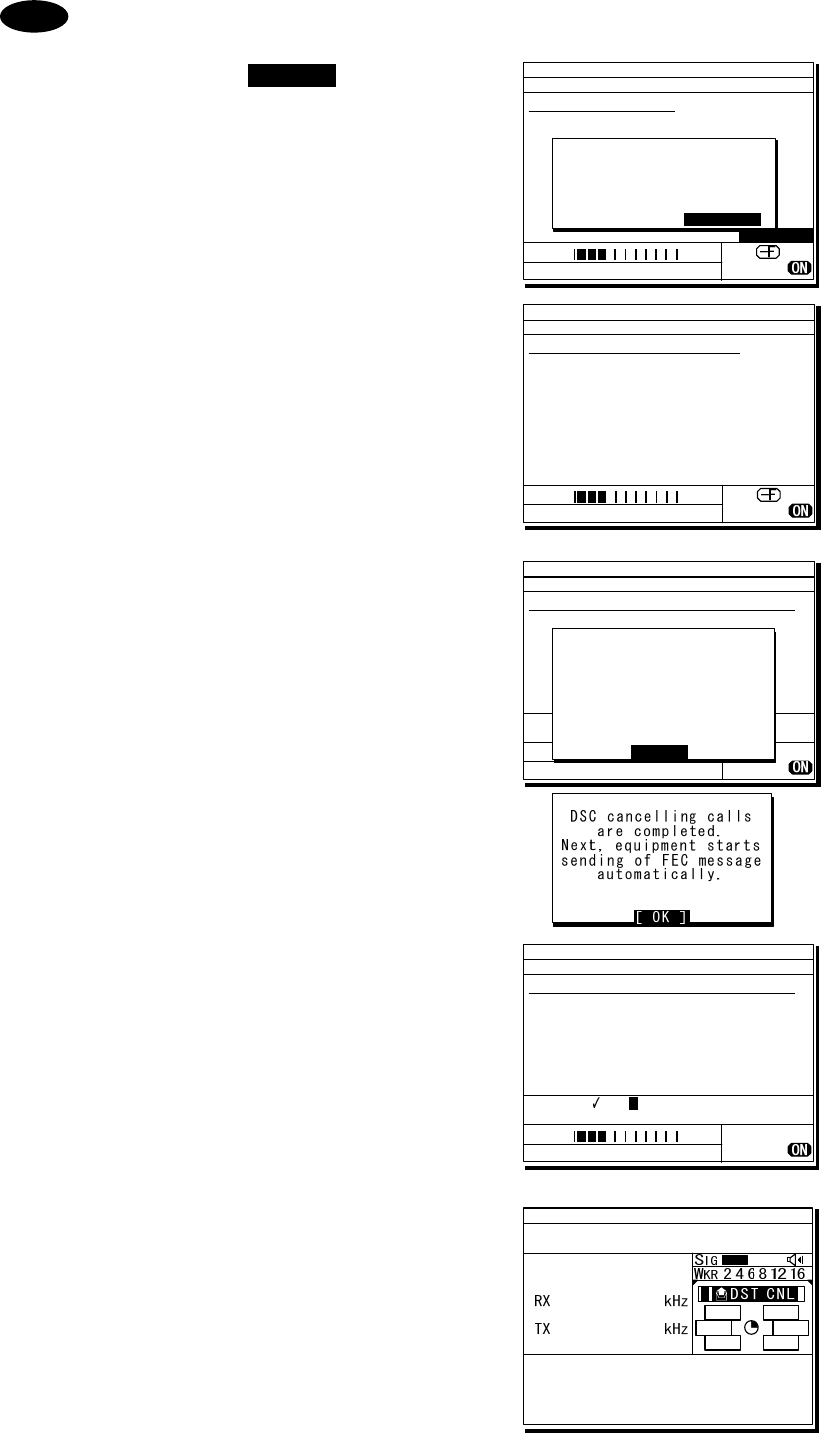
Operation
4-48
If cancelling the distress alert since a false distress alert is transmitted
accidentally, perform the distress alert cancelling procedure as follows.
1. Press the CANCEL key while
the option selectable screen
is focused.
2. On the popup screen, select
Continue with the jog dial,
and press ENT.
Starts the distress alert cancelling
procedure and sends the DSC
acknowledgements to own ship in
every frequency where distress
alerts are transmitted.
3. After DSC acknowledgements
are complete, the popup screen
is displayed as shown at right.
If the false distress alert indicates
the FEC mode, the popup screen is
displayed as shown at lower right.
In this case, the message for
cancelling distress alert is sent in
the TLX mode automatically
without operating the DTE.
4. According to the guidance on
the screen, broadcast to cancel
the distress alert in TEL mode.
¾ When finishing the broadcast on
a frequency, press ENT to change
to the next frequency.
¾ The cancelled frequency shows
✓
mark.
5. When the cancelling procedure is
completed on every frequency,
displays the operating screen as
shown at right and finishes the
distress mode.
Note
ID 431001234 23:59(UTC)
TEL Rx: 8291.0/Tx: 8291.0kHz
Distress calling
Next :Resends 3.8min later
Stage :Waiting for ACK
Call-F:2/4/6/8/12/16
Nature:Undesignated
PosUTC: 89゚59.0123'N
:179゚59.6789'E @23:59
Mode :Radiotelephone
[FRQ][Pause][POS][CHNG][Cancel]
[Cancel]
!!Warning!!
Cancel the transmitted
false distress alert?
(TGT: 2/4/6/8/12/16M)
[Continue] [Return][Return]
SIG
WKR 2 4 6 8 12 16MHz
ID 431001234 23:59(UTC)
DSC Rx: 2187.5/Tx: 2187.5kHz
Distress cancel calling
Stage :Waiting for CH free
Call-F: / / / / /
Nature:Undesignated
PosUTC: 89゚59.0123'N
:179゚59.6789'E @23:59
Mode :Radiotelephone
SIG
WKR 2 4 6 8 12 16MHz
ID 431001234 23:59(UTC)
TEL Rx: 2182.0/Tx: 2182.0kHz
Cancelling the distress alert
Voice cancellation procedure:
All stations. (three times)
This is [NAME][CALL SIGN]
[MMSI][POS&UTC].
Cancel my distress alert of
[DATE][UTC].
Over.
Target: 2/ 4/ 6/ 8/ 12/ 16MHz
*To change the band, press ENT.
SIG
WKR 2 4 6 8 12 16MHz
DSC cancelling calls
are completed. Next,
start the voice cancel
on the required bands
according to the
message on the screen.
[ OK ]
[ OK ]
TEL
2182.0
2182.0
ID 431001234 23:59(UTC)
Pos 89゚59.0123'N
179゚59.6789'E@23:59 (EXT)
TxTO:All|DST|ACK
Cancelled DISTRESS (00.2min)
Call-F:2/4/6/8/12/16
[RTRY][INF][FRQ][HLD][END]
A A
ID 431001234 23:59(UTC)
TEL Rx: 4125.0/Tx: 4125.0kHz
Cancelling the distress alert
Voice cancellation procedure:
All stations. (three times)
This is [NAME][CALL SIGN]
[MMSI][POS&UTC].
Cancel my distress alert of
[DATE][UTC].
Over.
Target: 2/ 4/ 6/ 8/ 12/ 16MHz
*To change the band, press ENT.
4
SIG
WKR 2 4 6 8 12 16MHz
Operation
4-49
4
4.
.5
5.
.5
5.
.2
2
Distress alerts from the menu
During communicating in telex mode, finish it to enable the menu before practicing below.
The following describes the procedure to send a distress alert with the nature of distress selected
in the menu. Also, besides manually inputting position and the time information, the subsequent
communication mode, the transmission method and frequency can be set here.
Note: Multi-frequency or single frequency can be selected as the transmission method. The
various methods are shown below.
⋅ Multi-frequency method: The distress alert message is sent continuously on each
frequency, 2187.5 kHz, 8414.5 kHz, and at least one
other distress/safety frequency.
⋅ Single frequency method: The same distress alert message is sent on one
distress/safety frequency 5 times continuously. If 2 or
more distress/safety frequencies are selected, the same
message is transmitted 5 times continuously in the same
way on the other frequency after an interval between 3.5
to 4.5 minutes (variable).
■ Procedure ■
1
1
1.
.
.
On the status display or operation display,
while pressing and holding MENU key, press
3 NR key to open “3. Editing a distress msg”.
The distress type is displayed as
Undesignated as a default value. If the
position information is input automatically by
a GPS type device, or has already input
manually, that information is also displayed.
2
2
2.
.
.
Press ENT and select the nature of distress.
The nature of distress is selectable from below.
Nature of distress Contents
Fire Fire, explosion
Flooding Flooding
Collision Collision
Grounding Grounding
Listing Listing, in danger of
capsizing
Sinking Sinking
Disabled Disabled and adrift
Undesignated Undesignated distress
Abandoning Abandoning ship
Piracy attack Piracy/armed robbery
attack
Man overboard Man overboard
3)Editing a distress msg
Nature :[Undesignated ]
Position :[NE]
:[ 89゚59.0123'N]
:[179゚59.6789'E]
UTC of pos :[23:59]
Mode(fixed) :[Radiotelephone]
Attempt type:[Multi-FRQ ]
Tx bands :[2/4/6/8/12/16]
[Preview] [Tips] [Cancel]
3)Editing a distress msg
Nature :[Fire ]
Position :[NE]
:[ 89゚59.0123'N]
:[179゚59.6789'E]
UTC of pos :[23:59]
Mode(fixed) :[Radiotelephone]
Attempt type:[Multi-FRQ ]
Tx bands :[2/4/6/8/12/16]
[Preview] [Tips] [Cancel]
Attention

Operation
4-50
3
3
3.
.
.
Press ENT.
The cursor moves to Position. If a valid position
and time of that position are already displayed,
no entry is necessary. Skip to step 6.
4
4
4.
.
.
Press ENT and select the quadrant of the
position with the jog dial.
The quadrant changes from NE Æ NW Æ SE
Æ SW Æ CL. Select CL to delete the input
information.
5
5
5.
.
.
After pressing ENT, input the latitude,
longitude, and time using the numeric
keypad.
6
6
6.
.
.
Press ENT and select the Mode to
change the subsequent communication
mode after the DSC call.
Either of Radiotelephone or FEC is selectable
for the subsequent communicate mode.
7
7
7.
.
.
Move the cursor to Attempt type and
press ENT to change the transmission
method for the distress alert.
Multi-frequency method is set as the default.
To change to the single frequency method,
select Single-FRQ with the job dial and press
ENT.
8
8
8.
.
.
Move the cursor to Tx bands and press
ENT to change the transmission
frequency for the distress alert.
¾ At first, all the frequencies are selected
as transmission frequencies.
¾ To change the frequencies, move the
cursor by pressing ENT to the frequencies
(band) to be unselected, turn the jog dial
so they are blank and press ENT.
¾ For the Multi-frequency method, 2 and 8
are fixed and are skipped. Also in this
case, it is necessary to select more than
one other band.
¾ After completing the Tx bands settings,
the cursor returns to Nature.
3)Editing a distress msg
Nature :[Fire ]
Position :[NE]
:[ 89゚59.0123'N]
:[179゚59.6789'E]
UTC of pos :[23:59]
Mode(fixed) :[Radiotelephone]
Attempt type:[Multi-FRQ ]
Tx bands :[2/4/6/8/12/16]
[Preview] [Tips] [Cancel]
3)Editing a distress msg
Nature :[Fire ]
Position :[NW]
:[ 89゚59.0123'N]
:[179゚59.6789'E]
UTC of pos :[23:59]
Mode(fixed) :[Radiotelephone]
Attempt type:[Multi-FRQ ]
Tx bands :[2/4/6/8/12/16]
[Preview] [Tips] [Cancel]
3)Editing a distress msg
Nature :[Fire ]
Position :[NW]
:[ 89゚59.0123'N]
:[179゚59.6789'W]
UTC of pos :[23:59]
Mode(fixed) :[Radiotelephone]
Attempt type:[Multi-FRQ ]
Tx bands :[2/4/6/8/12/16]
[Preview] [Tips] [Cancel]
3)Editing a distress msg
Nature :[Fire ]
Position :[NW]
:[ 89゚59.0123'N]
:[179゚59.6789'W]
UTC of pos :[23:59]
Mode(fixed) :[Radiotelephone]
Attempt type:[Single-FRQ]
Tx bands :[2/ /6/8/12/16]
[Preview] [Tips] [Cancel]
3)Editing a distress msg
Nature :[Fire ]
Position :[NW]
:[ 89゚59.0123'N]
:[179゚59.6789'W]
UTC of pos :[23:59]
Mode :[Radiotelephone]
Attempt type:[Multi-FRQ ]
Tx bands :[2/4/6/8/12/16]
[Preview] [Tips] [Cancel]
3)Editing a distress msg
Nature :[Fire ]
Position :[NW]
:[ 89゚59.0123'N]
:[179゚59.6789'W]
UTC of pos :[23:59]
Mode(fixed) :[Radiotelephone]
Attempt type:[Single-FRQ]
Tx bands :[2/4/6/8/12/16]
[Preview] [Tips] [Cancel]
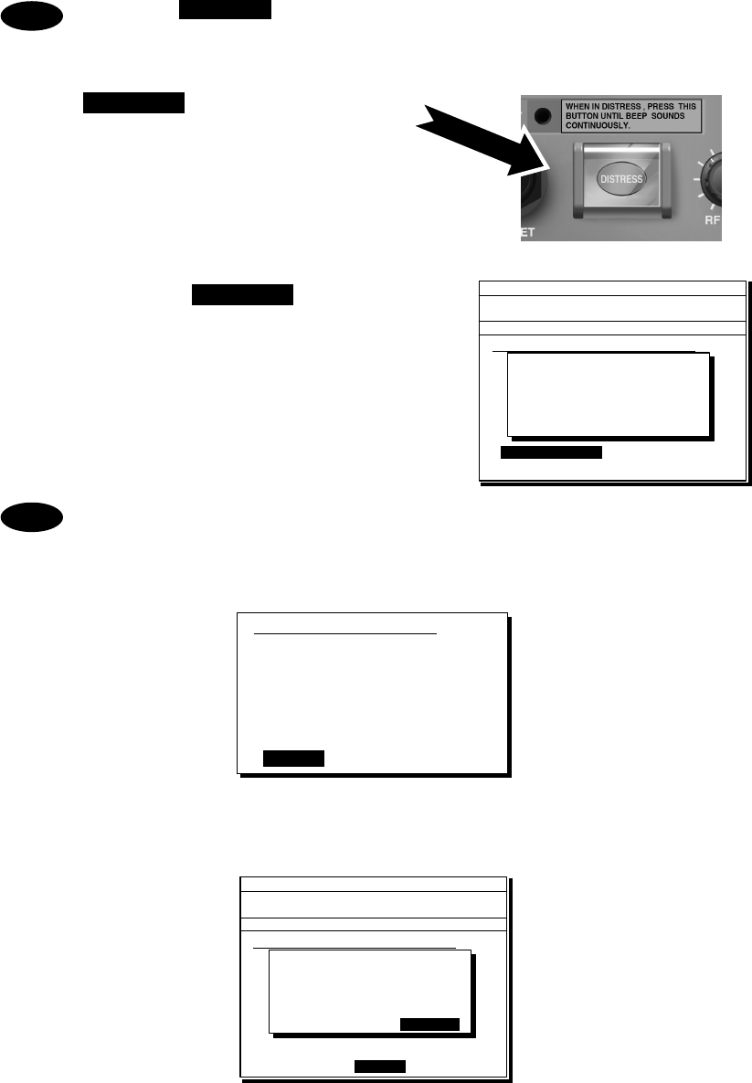
Operation
4-51
If pressing DISTRESS key during the Tx bands settings (before fixing by pressing
ENT), the distress alerts are sent on the band(s) registered previously.
9
9
9.
.
.
Open the DISTRESS key cover.
1
1
10
0
0.
.
.
Press and hold the DISTRESS key for 4
seconds until the countdown is
completed.
- The rest of the procedure is the same as described in the "Quick distress
alerts".
- Select Preview and press ENT before calling to display the details of the
message as shown below.
- Select Tips and press ENT to display precautions about operations in this
screen in a popup screen as shown below.
This popup screen shows the following messages and the handling menus;
・ When sending the edited message, use DISTRESS key on the menu screen.
・ To save the edited message (except Pos/UTC), select Save and press ENT.
・ To load the saved message (except Pos/UTC), select Set and press ENT.
・ The default values of “3. Editing a distress msg” are not changed.
Note
3)Editing a distress msg
Format :Distress
Self-ID :431001234
Nature :Fire
Position : 89゚59.0123'N
:179゚59.6789'E
UTC of pos :23:59
Comm type :Radiotelephone
EOS :EOS
[Return] [Tips] [Cancel]
ID 431001234 23:59(UTC)
Pos 89゚59.0123'N
179゚59.6789'E@23:59 (EXT)
DSC Rx: 2177.0/Tx: 2177.0kHz
3)Editing a distress msg
Nature :[Undesignated ]
Position :[NE]
[ 89゚59.0123'N]
[179゚59.6789'E]
UTC of pos :[23:59]
Mode :[Radiotelephone]
Attempt type:[Multi-FRQ ]
Tx bands :[2/4/6/8/12/16]
[Preview] [Tips] [Cancel]
Tx bands
Distress call starts
in sec
4
Note
ID 431001234 23:59(UTC)
Pos 89゚59.0123'N
179゚59.6789'E@23:59 (EXT)
TEL Rx: 4015.0/Tx: 4015.0kHz
3)Editing a distress msg
Nature :[Fire ]
Position :[NW]
[ 89゚59.0123'N]
[179゚59.6789'W]
UTC of pos :[23:59]
Mode(fixed) :[Radiotelephone]
Attempt type:[Single-FRQ]
Tx bands :[2/ /6/8/12/16]
[Preview] [Tips] [Cancel]
[Tips]
- Press DISTRESS key to
send the edited msg.
- To save DIST msg:Save
- To use saved msg:Set
NB)DEFAULT NOT CHANGED.
[Save] [Set] [Close]
[Close]
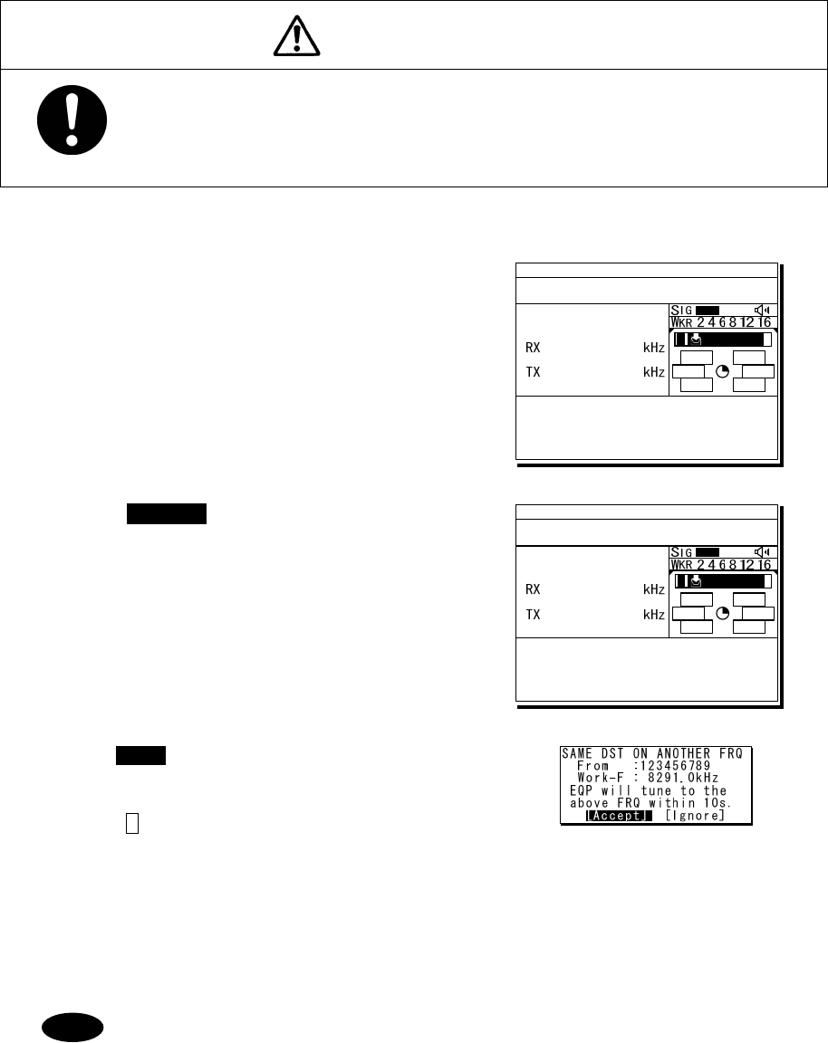
Operation
4-52
4
4.
.5
5.
.5
5.
.3
3
Receiving distress alerts
When a distress alert is received from another ship, displays the event immediately with the
specific two-tone alarm sound.
WARNING
If a distress alert is received, make sure to inform the ship's captain or
officer in charge. Doing so may save the lives of the crews and passengers
on the ship in distress.
■ Procedure ■
1
1
1.
.
.
When a distress alert is received, the
distress message is displayed.
¾ The ALM lamp starts blinking, and the receiving
alarm gradually grows louder. However, the
aural alarm keeps silence if the distress
position is not within 500nm, and is not in the
polar areas (greater than 70°N/S).
¾ If no procedure exists, starts operating the
received message automatically.
2
2
2.
.
.
Press the CANCEL key or ENT to stop the
alarm. Then the screen at right is displayed.
¾ Keep watch for at least 5 minutes. Notify
the coast station as appropriate.
¾ If received the same distress alert on another
frequency again, the right lower screen is
displayed. Then pressing ENT on Accept or
leaving 10 seconds changes the frequency to
8291.0 kHz for the radiotelephone mode or
8376.5 kHz for the telex mode.
¾ Press FUNC key or ENT* to move the focused
screen to the operation control screen and select
the following options to handle the procedure.
* If the A mark is not displayed, press ENT to
activate this procedure.
ACK ....... Sends the acknowledgement to the distress alert.
RLY ....... Sends the distress relay.
INF ........ Indicates the received distress message.
FRQ....... Changes the watchkeeping frequency.
HLD ....... Makes the procedure on hold.
END....... Terminates the procedure.
- The distress acknowledgement is normally sent from a coast station. However
after consulting with the RCC or a coast station and being directed, it is
possible to acknowledge the ship in distress from your own ship.
- If the distress alert is not received at 2187.5 kHz, the acknowledgement is
inhibited and cannot be sent.
- Incase of the radiotelephone specified, after sending the acknowledgement the
frequency is set to 2182.0 kHz. Then start the radiotelephone communication
TEL
2182.0
2182.0
ID 431001234 23:59(UTC)
Pos 89゚59.0123'N
179゚59.6789'E@23:59 (EXT)
RxID:123456789|DISTRESS ALT
Waiting to send ACK(00.2min)
Single-FRQ: 2187.5kHz
TEL :Rx 2182.0/Tx 2182.0KHz
Press CANCEL to silence alarm.
A DST ALT
TEL
2182.0
2182.0
ID 431001234 23:59(UTC)
Pos 89゚59.0123'N
179゚59.6789'E@23:59 (EXT)
RxID:123456789|DISTRESS ALT
Waiting to send ACK(00.3min)
Single-FRQ: 2187.5kHz
TEL :Rx 2182.0/Tx 2182.0kHz
[ACK][RLY][INF][FRQ][HLD][END]
A DST ALT
Note
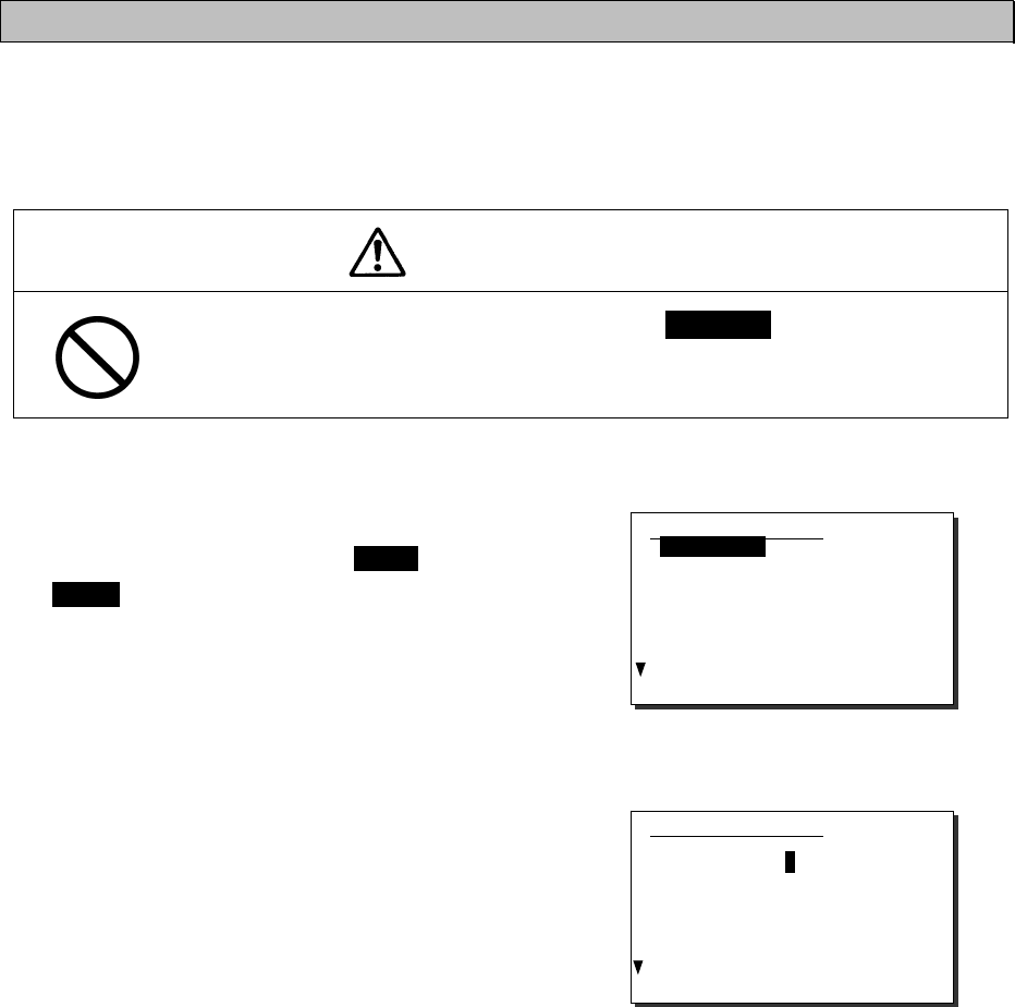
Operation
4-53
with the ship in distress according to the following procedure.
z Say "MAYDAY".
z Repeat the identity (MMSI) of the ship in distress 3 times
z Say "This is..."
z Repeat the identity (MMSI) of your ship 3 times
z Say "RECEIVED MAYDAY".
- Incase of the FEC specified, after sending the acknowledgement the frequency
is set to 2174.5 kHz. Then start the telex communication with the data terminal.
- The distress relay calls may be received without receiving the distress alert. In
this case, keep watch the distress frequency and handle the message using
the displayed options as appropriate.
4.5.6 Distress relay calls on behalf of someone else (DROBOSE)
If another ship is in distress but is itself unable to make a distress alert, and the master of the
ship considers that further help is necessary, the distress relay call on behalf of the ship can be
transmitted using the "DSC drobose call" menu. In this case, compose a distress relay call format
by inputting the MMSI (if known), the ship's position and the time of position (if known), and the
nature of distress to send to a specific area or a coast station.
CAUTION
When sending a drobose call, do NOT press the DISTRESS key. Doing so may
cause a false distress alert.
(Drobose calls can be sent via the [Call] button displayed on the screen.)
■ Procedure ■
1
1
1.
.
.
On the status display or operation display,
while pressing and holding MENU key, press
2SCAN key to open “2. DSC drobose call”.
2
2
2.
.
.
Select Address and press ENT, input the
MMSI of the calling coast station.
2)DSC drobose call
Format :[Individual]
Address :[ ]
Distress ID:[ ]
Nature :[Undesignated ]
Position :[ ]
:[ ゚ . ' ]
:[ ゚ . ' ]
UTC of pos :[ : ]
[Call] [Preview] [Cancel]
2)DSC drobose call
Format :[Individual]
Address :[0 ]
Distress ID:[ ]
Nature :[Undesignated ]
Position :[ ]
:[ ゚ . ' ]
:[ ゚ . ' ]
UTC of pos :[ : ]
[Call] [Preview] [Cancel]
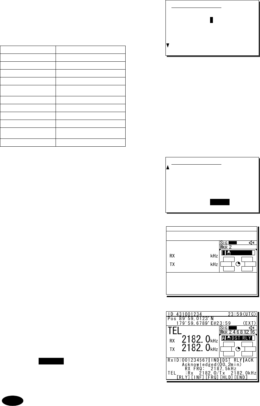
Operation
4-54
3
3
3.
.
.
Input the Distress ID (MMSI) of the ship
in distress, Nature, Position and/or UTC,
if known.
The nature of distress is selectable from below.
Nature of distress Contents
Fire Fire, explosion
Flooding Flooding
Collision Collision
Grounding Grounding
Listing Listing, in danger of
capsizing
Sinking Sinking
Disabled Disabled and adrift
Undesignated Undesignated distress
Abandoning Abandoning ship
Piracy attack Piracy/armed robbery
attack
Man overboard Man overboard
4
4
4.
.
.
If required, change the communication
mode and/or the calling frequency to
send the drobose call.
Mode: Radiotelephone or FEC
Calling FRQ: Distress and safety frequency
(2/4/6/8/12/16 MHz)
5
5
5.
.
.
Select Call and press ENT to make a
drobose call.
After sending the drobose call, TEL mode is
set while waiting for the acknowledgement as
shown at right. In this case, the watchkeeping
receiver stops scanning frequencies to watch
only the calling frequency as shown at right.
6
6
6.
.
.
When receiving the acknowledgement
from the coast station, the screen shows
as shown at right.
¾ The ALM lamp starts blinking, and the
receiving alarm gradually grows louder.
¾ Press the CANCEL key or ENT to silence
the alarm, then start the distress traffic.
Such messages can be sent using Area format. In this case, select Area (centre
or corner) for the broadcast communication.
2)DSC drobose call
Format :[Individual]
Address :[001234567]
Distress ID:[0 ]
Nature :[Undesignated ]
Position :[ ]
:[ ゚ . ' ]
:[ ゚ . ' ]
UTC of pos :[ : ]
[Call] [Preview] [Cancel]
2)DSC drobose call
Distress ID:[123456789]
Nature :[Fire ]
Position :[NE]
:[ 89゚59.0000'N]
:[179゚59.0000'E]
UTC of pos :[23:59]
Mode :[Radiotelephone]
Calling FRQ:[ 2187.5kHz]
[Call] [Preview] [Cancel]
Note
TEL
2182.0
2182.0
ID 431001234 23:59(UTC)
Pos 89゚59.0123'N
179゚59.6789'E@23:59 (EXT)
TxTO:001234567|IND|DST RLY
Waiting for ACK(00.5min)
Call-F:Rx 2187.5/Tx 2187.5kHz
TEL :Rx 2182.0/Tx 2182.0kHz
[RLY][INF][FRQ][HLD][END]
A DST RLY
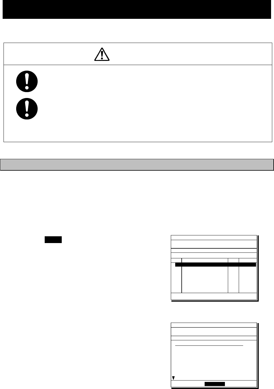
Operation
4-55
4.6 DSC call log
DSC messages are classified as received distress messages, received other messages and
transmitted messages. The 20 most recent messages for every type are saved in the log.
CAUTION
Received distress message logs are automatically deleted after 48 hours to
avoid accidental resending or other misoperation. Accordingly, if such
messages cannot be read, it is not a malfunction.
The received distress message logs are cleared when turning off the power
by such as the breaker on the power supply. Due to the SOLAS Convention
(keeping watch on distress and safety frequencies at all times), do not turn
off the equipment when at sea.
4.6.1 Received distress messages
The distress alerts, the distress acknowledgements, the distress relay calls, and the distress
relay acknowledgements are stored in this log. For the distress alerts, the messages with the
same content are received at a maximum of 6 messages for the multi-frequency method or a
maximum of 5 messages for the single frequency method, but only one is stored unless otherwise
closed the received message during that multiple receptions.
■ Procedure ■
1
1
1.
.
.
Press the MENU key, and through
hierarchical menus, select “4.1 Received
distress”.
¾ On the bottom line, the MMSI of the ship
is displayed highlighted by the cursor.
¾ If the message includes a reception error
(ECC error) ERR is shown in the CAT
field.
2
2
2.
.
.
Select a displayed message and press
ENT.
ID 431001234 23:59(UTC)
Pos 89゚59.0123'N
179゚59.6789'E@23:59 (EXT)
TEL Rx: 4125.0/Tx: 4125.0kHz
4.1)Received distress
No Date/Time CAT Format
01 2008-07-31 11:20 DST ALL
02 2008-07-31 10:33 DST INDIV
03 2008-07-31 10:25 DST AREA
04 2008-07-31 10:03 --- DSTRS
05 2008-07-19 22:53 ERR DSTRS
01 2008-08-01 23:31 DST INDIV
From: 431000123
ID 431001234 23:59(UTC)
Pos 89゚59.0123'N
179゚59.6789'E@23:59 (EXT)
TEL Rx: 2065.0/Tx: 2065.0kHz
Received distress message
Type :Distress
From :003456789
Nature :Man overboard
Position :12゚34.0000'N
123゚45.0000'E
UTC of pos:11:20
Mode :Radiotelephone
EOS :EOS
[Close]
[Close]
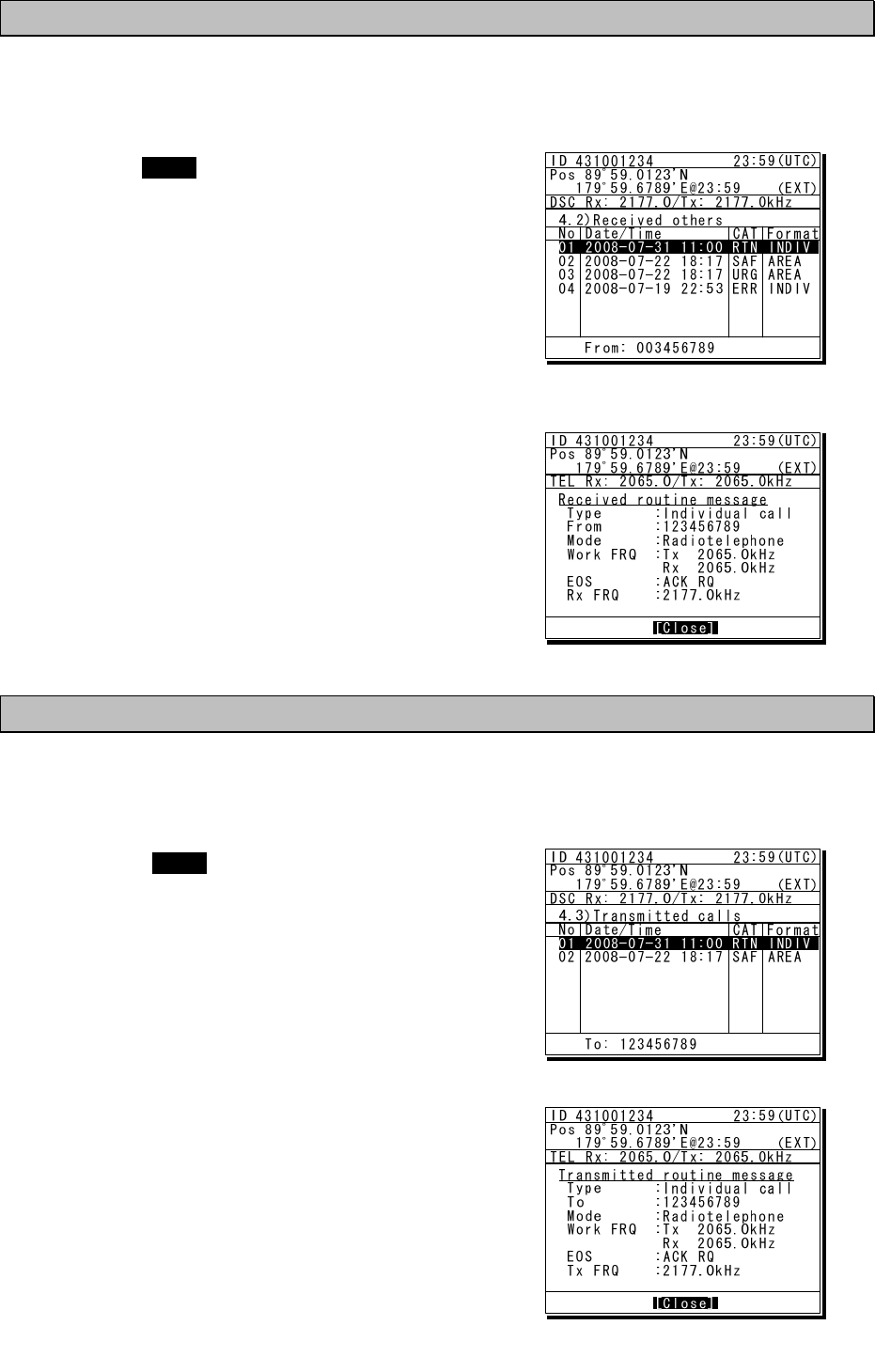
Operation
4-56
4.6.2 Received other messages
Received messages other than the distress (routine, safety, and urgency) are stored in this log.
■ Procedure ■
1
1
1.
.
.
Press the MENU key, and through
hierarchical menus, select “4.2 Received
others”.
¾ On the bottom line, the MMSI of the ship
is displayed highlighted by the cursor.
¾ If the message includes a reception error
(ECC error) ERR is shown in the CAT
field.
2
2
2.
.
.
Select a displayed message and press
ENT.
The selected message is displayed.
4.6.3 Transmitted messages
Every transmitted message is stored in this log.
■ Procedure ■
1
1
1.
.
.
Press the MENU key, and through
hierarchical menus, select “4.3 Transmitted
calls”.
On the bottom line, the MMSI of the ship is
displayed highlighted by the cursor.
2
2
2.
.
.
Select a displayed message and press ENT.
The selected message is displayed.
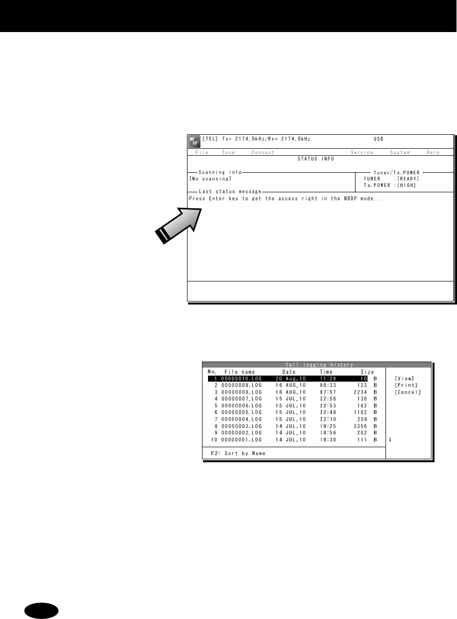
Operation
4-57
4.7 Display of telex communication logs
The telex communication is saved automatically as the log, and the reference is available later.
■ Procedure ■
1
1
1.
.
.
If displaying the message of "Press Enter key to get the access right in the NBDP
mode…" on the data terminal, press Enter key on the keyboard.
The operation of the data
terminal becomes possible in
the telex mode, except when
the controller is used.
2
2
2.
.
.
On the main menu and the dropdown menu, select Service Î Call logging history with
Enter key.
The list of the log as shown at
right is displayed.
3
3
3.
.
.
Move the cursor to the objective file referring to the timestamp and press Enter key to
view it.
¾ The file content on the viewer scrolls by the ↑↓ key.
¾ To close the file viewer, press the ESC key.
The maximum size of a log file is 8192 bytes. When exceeding it, the excess data
are stored in another file.
Note
Operation
4-58
4.8 USB memory operation
This section describes how to use the USB memory.
・ The following conditions are required for the USB memory.
Note) Not all USB memories satisfying the every condition are guaranteed.
- The specification is complied with USB 1.1 or USB 2.0 standards.
- No USB hub is built-in and is used to connect the USB memory.
- No security function such as encryption or password to access is included.
- No write-protect function is included, or that function is set to “Writable”.
- Already formatted with FAT16 or FAT32 by Windows® OS.
・ Only the USB memory is connectable to the USB memory connector.
・ When the USB memory size is large, the file access time will be longer than small one.
・ The files or folders named with multibyte character prepared by other than the data terminal
cannot be accessed.
・ If the USB memory is removed, always close the connector with the rubber cap to ensure the
water-proof and dust-proof performance.
・ Initializing the USB memory will erase all data on the USB memory.
・ To avoid abnormal conditions, do not use the USB memory that has the broken file system.
■ Procedure ■
1
1
1.
.
.
If displaying the message of "Press Enter key to get the access right in the NBDP
mode…" on the data terminal, press Enter key on the keyboard.
The operation of the data
terminal becomes possible in
the telex mode, except when
the controller is used.
2
2
2.
.
.
After checking the USB mark indicating on the top of the display of the data terminal,
select File from the main menu and the objective dropdown menu.
¾ To start either one of Edit existing file, Rename file, Delete file, or Copy file, input “A:” as
the USB drive.
¾ To initialize the USB memory, select Initialize USB and operate in accordance with the
message on the dialog box.
¾ To unmount the USB memory, select Remove USB and operate in accordance with the
message on the dialog box. After completing the unmount and the USB mark of the top of
the display is erased, the USB memory can be safely removed from the data terminal.
Attention
[TEL] Tx= 2174.5kHz/Rx= 2174.5kHz USB
File Tune Connect Service System Help
STATUS INFO
[No scanning] TUNER :[READY]
Tx.POWER :[HIGH]
Press Enter key to get the access right in the NBDP mode...
Scanning info Tuner/Tx.POWER
Last status message

Operation
4-59
4.9 Popup screens
The contents of the popup screens of the data terminal are as follows (in alphabetical order).
Message Buttons Description
Attention
Are you sure to erase? Yes/ No
Is it OK to delete a file?
Yes: Deletes the file.
No: Cancels this operation.
Attention
Are you sure to initialize all of these
accessible setup data?
Yes/ No
Is it OK to initialize the all items
where the cursor can be located.
Yes: Initializes them.
No: Cancels this operation.
Attention
Do you really want to change column width? Yes/ No
Is it OK to change the column width
of a line?
Yes: Changes the column width.
No: Cancels this operation.
Attention
Formatting will erase all data on the USB
memory. To format the USB memory, choose
Yes.
Yes/ No
All the data of USB memory is
deleted by the format operation.
Yes: Formats the USB memory.
No: Cancel the format.
Attention
Keyboard input unavailable now.
The connected controller is in operation.
-----
The controller is in operation such as
menu and the data terminal cannot
be operated now.
Attention
The antenna tuning is started by the
controller. Wait a moment, please.
-----
Now tuning the antenna with the
controller, and unavailable for a
while.
Attention
The current database will be lost.
Are you sure to continue?
Yes/ No
Is it OK to overwrite the current
database file to save the new one?
Yes: Overwrites the current file.
No: Cancels this operation.
Attention
The DTE cancels the print request for the
DTE printing buffer overflow.
OK
The print request from the controller
or by the data terminal operation has
been refused for the printing buffer
overflow.
Attention
The file size exceeds the maximum value,
so the DTE deletes excess data. Are you
sure?
Yes/ No
When saving a file, detected the file
size is exceeding the 8kB. The data
terminal can delete the excess data
and continue to save the file.
Yes: Continues the process.
No: Cancels this operation.
Attention
The maximum field size is reached. OK The editing message file size is now
beyond 8kB. Please downsize it.
Attention
The same file name already exists.
Do you overwrite it?
Yes/ No
The same file name exists. Is it 0K to
overwrite it?
Yes: Overwrites the current file.
No: Cancels this operation.
Block has not marked.
This function is impossible now. OK No block is selected and refused the
request. Select a block in advance.
Confirmation
Is the frequency free now? Yes/ No
Check the frequency is busy or not.
Yes: Continues the process.
No: Returns to the menu
Continue Search? Yes/ No
Continue searching the string
specified?
Yes: Continues searching.
No: Cancels this operation.

Operation
4-60
Message Buttons Description
Error
File access failed. OK The specified file cannot be used for
any malfunction.
Error
Invalid file. OK The file is malformed and invalid.
Error
Keyboard I/F ROM checksum error. OK Detected the keyboard I/F ROM
checksum error.
Error
No folder exists. OK A specified folder is not found.
Error
No response. OK The controller may be busy and
returns no reply to the data terminal.
Error
Overcurrent has been detected at the USB
port.
OK The attached USB device may be
failure.
Error
Register the 9-digit Self-ID in advance. OK
Own station ID (9digit selcal number)
is needed to call the station by the 9
digit selcal number.
Error
Register this station's ID in advance. OK Own station ID is needed to call the
station in the telex mode.
Error
The antenna is not tuned correctly.
Tune to the frequency now?
Yes/ No
The antenna is not tuned. Starts the
antenna tuning immediately?
Yes: Tunes immediately.
No: Tuning is not needed.
Error
The attached USB device is not supported.
The DTE supports the USB memory only.
OK The data terminal detects the USB
device except the USB memory.
Error
The DTE failed to access to the file system. OK The file system and the files are
inaccessible now.
Error
The DTE failed to print. OK Printing is unavailable now.
Error
The DTE failed to stop the USB drive. OK The USB drive cannot be unmounted.
Error
The DTE was unable to complete the
format. Please remove the USB memory.
OK
The data terminal failed to format the
USB memory, so remove the USB
memory.
Error
The file is too large. OK
The specified file cannot be opened
because of the file size beyond the
8kB.

Operation
4-61
Message Buttons Description
Error
The file name extension is allowed only
“DB”.
OK Input “DB” as the correct extension.
Error
The file name extension is allowed only
“TLX”.
OK Input “TLX” as the correct extension.
Error
The file name is wrong. OK The specified file is not found, or
the file name to be copied is wrong.
Error
The file saving failed.
There is not enough room on the DTE drive.
OK
No file can be saved because the
data terminal has no sufficient
vacant memory.
Error
The keyboard is disconnected. -----
The keyboard is disconnected and no
control for the data terminal is
available now.
Error
The keyboard is not ready. -----
Malfunction is detected at the
keyboard I/F and the keyboard is no
longer available now.
Error
The memory is already full.
So you cannot make a new file.
OK
The number of files exceeded
maximum value (100), so a new file
cannot be made.
Error
The printer is not ready.
Check the paper and online status.
OK
The printer cannot be used. Confirm
that paper is put on or that it is
online.
Error
The same file name already exists. OK This file name already exists, and is
no longer available now.
Error
The station ID is not present. OK
SELCAL number (ID) is not
registered in the specified radio
station.
Error
There is a possibility of the USB IC failure.
All USB functions are disabled.
OK Detected the USB IC failure. And now
out of work here.
Error
There is not enough room on the DTE main
drive. Delete some files, or change the
folder.
OK
The data terminal has no sufficient
vacant memory. Delete files or
change the folder adequately.
Error
There is not enough room on the USB drive.
Delete some files, or change the folder.
OK
The USB memory has no sufficient
vacant area. Delete files or change
the folder adequately.
Error
Two or more channels are needed. OK
Register two or more channels to
start scanning of the specified
station..
Error
Tx/Rx frequency is not present. OK The frequency is not registered in the
specified radio station.

Operation
4-62
Message Buttons Description
Formatting the USB memory.
Please wait. ----- USB memory is being formatted.
Wait for a while.
Now printing.
Please wait. ----- It is printing.
Wait for a while.
Now reading data.
Please wait. ----- Information on the file and the folder
is being read. Wait for a while.
Now processing NBDP settings.
Please wait. ----- The NBDP setting information is now
being read or saved. Wait for a while.
Now saving data.
Please wait. ----- It is saving a file. Wait for a while.
Really quit without saving? Yes/ No
Is it OK to quit without saving?
Yes: Quits immediately
No: Returns to the editor.
Replace the string? Yes/ No
Continue to replace the strings
specified?
Yes: Replacing.
No: Cancels this operation.
String not found. OK The data terminal cannot find the
string searching.
The USB drive is installed and ready to use. OK Recognized the USB memory.
The USB memory can now be safely
removed from the DTE. OK Unmounting the USB drive was
completed.
The USB memory format complete. OK The format of USB memory was
completed.
There are no data to be restored. OK There are no data to be restored and
Undo is invalid.
To stop the USB drive, choose Yes. After
the USB drive is stopped, the USB drive
can be safely removed.
Yes/ No
Select Yes when you unmount the
USB drive. After unmounting, USB
memory can be removed.
Waiting for the tuner answer… -----
Now waiting for the answer from the
antenna tuner. Just a moment,
please.
Warning
The USB memory was removed without
unmounting that drive.
OK
Removing the USB memory without
unmounting may cause the
malfunction of the USB memory.
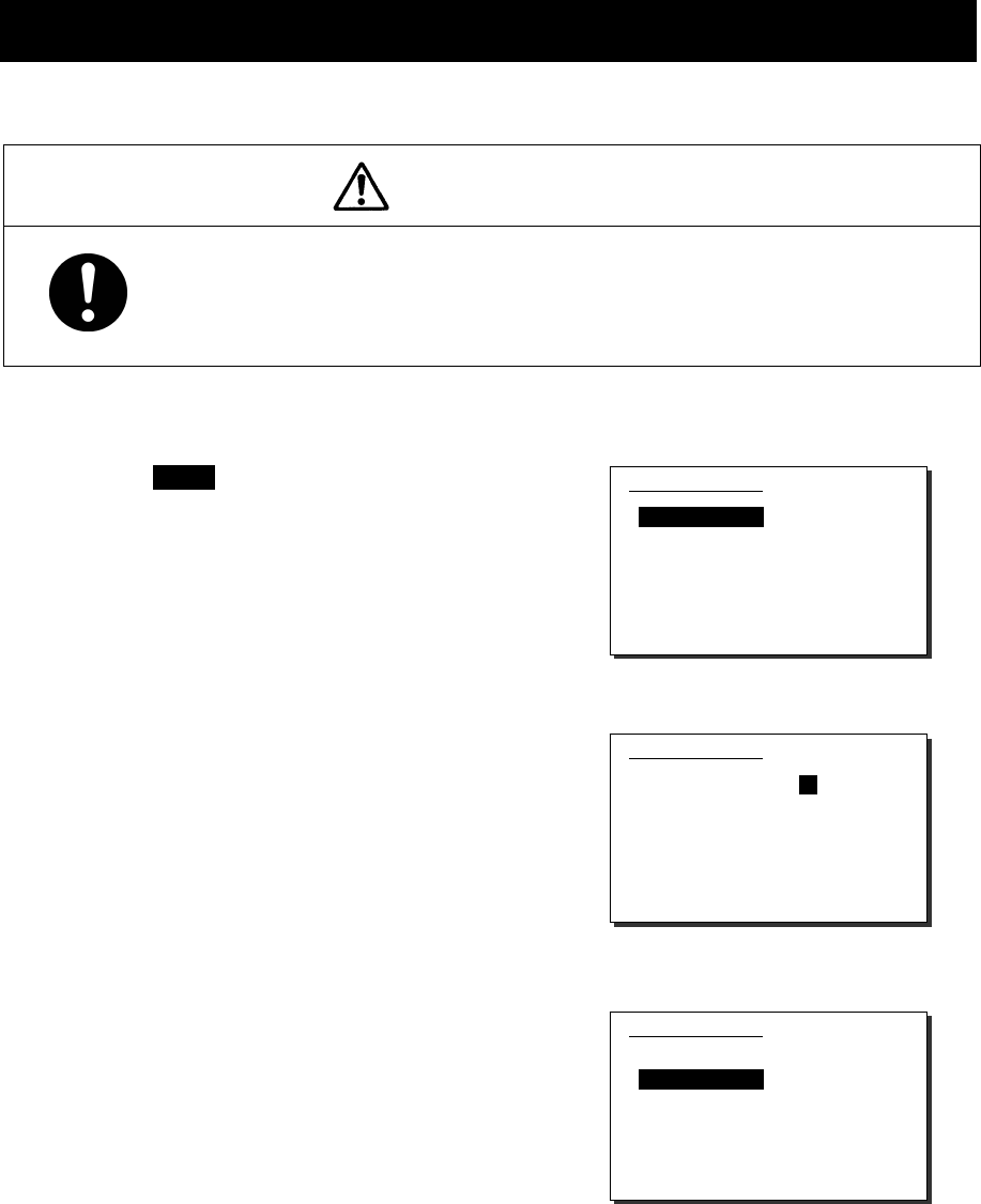
Settings & Registrations
5-1
5. SETTINGS & REGISTRATIONS
This chapter describes the procedures for settings and registrations such as manual date
and time settings, registration of channels in each mode, advanced DSC settings, printer
settings, and other settings for the equipment.
5.1 Date and time settings
Normally, the date and time are updated automatically if importing GPS information. But, if
necessary, input these parameters manually as follows.
CAUTION
The time in the 7.1 Date & time menu means the present time, and is
different from the time in the 7.2 POS/TIME menu that means the time
when the position information is valid.
■ Procedure ■
1
1
1.
.
.
Press the MENU key, and through
hierarchical menus, select 7.1 Date &
time.
2
2
2.
.
.
To input the date, press ENT.
Input the year, month, and date with the
numeric keypad or jog dial, and press ENT.
3
3
3.
.
.
After completing the above steps, the
cursor moves to 2. Present time.
7.1)Date & time
1.Date :2011-12-30
2.Present time :23:59
3.Display form
- UTC/LT :UTC
- LT diff : :
0.Back
7.1)Date & time
1.Date :2012-12-30
2.Present time :23:59
3.Display form
- UTC/LT :UTC
- LT diff : :
0.Back
7.1)Date & time
1.Date :2012-12-31
2.Present time :23:59
3.Display form
- UTC/LT :UTC
- LT diff : :
0.Back

Settings & Registrations
5-2
4
4
4.
.
.
To input the present time, press ENT.
¾ Input the hours and minutes with the
numeric keypad or jog dial, and press ENT.
¾ To close this menu after completing the
date and time settings, place the cursor
on any one of the selectable items and
press the CANCEL key.
In addition to the above, the following items can be set in this menu.
- UTC/LT: Select a type of time, Universal Time Coordinated (UTC) or Local
Time (LT), shown on the screen.
- LT diff: Set the local time difference to display the local time.
Note
7.1)Date & time
1.Date :2012-12-31
2.Present time :23:59
3.Display form
- UTC/LT :UTC
- LT diff : :
0.Back
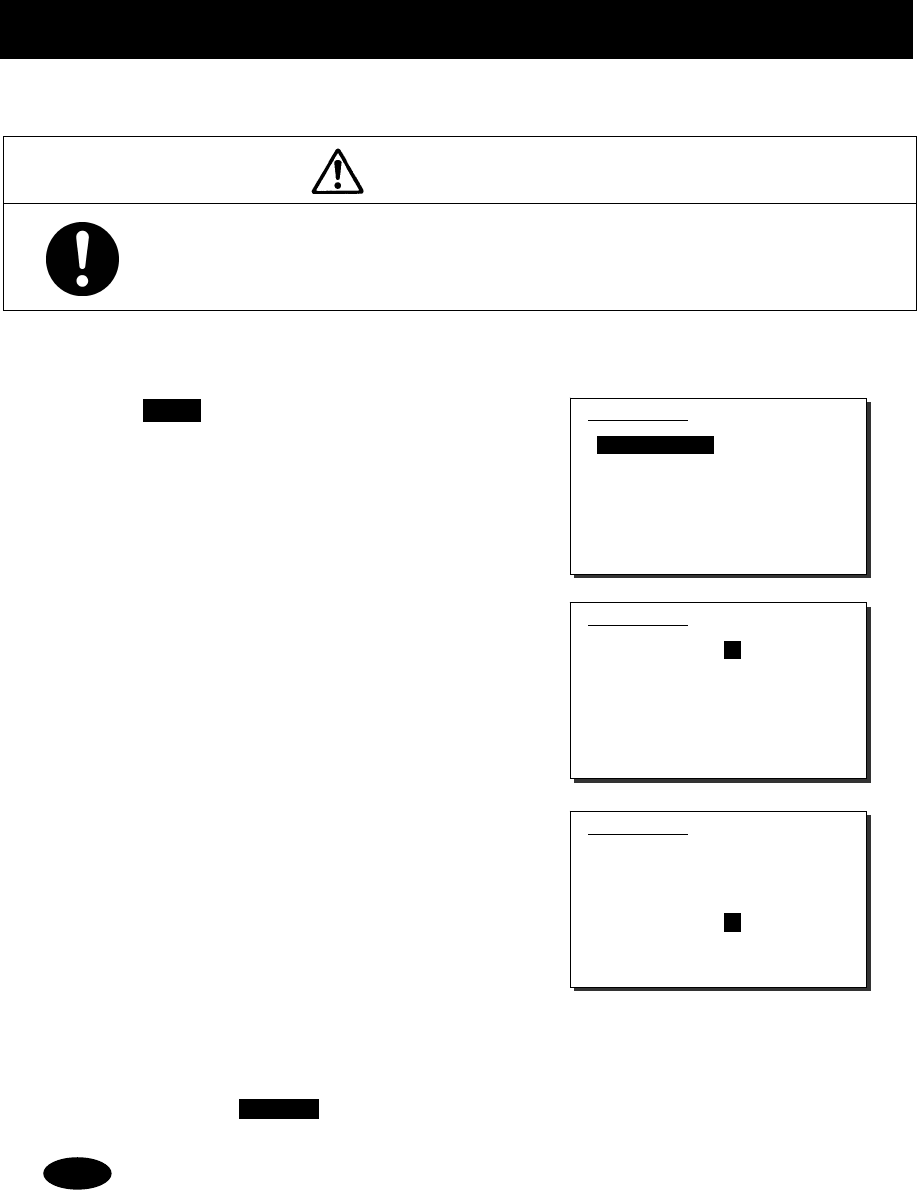
Settings & Registrations
5-3
5.2 Own ship position and time settings
Normally, the ship's position and the time are updated automatically if importing GPS information.
But, if necessary, input these parameters manually as follows.
CAUTION
The time in the 7.2 POS/TIME menu means the time when the position
information is valid, and is different from the present time mentioned in the
7.1 Date & time menu.
■ Procedure ■
1
1
1.
.
.
Press the MENU key, and through
hierarchical menus, select 7.2
POS/TIME.
2
2
2.
.
.
To input your own ship's position, press
ENT.
Select the position quadrant with the jog dial,
and press ENT. Then input the latitude and
longitude with the numeric keypad or jog dial,
and press ENT.
3
3
3.
.
.
When completing the input of the ship’s
position, the cursor moves to the time
column of the
2. UTC of position.
¾ Input the hours and minutes with the
numeric keypad or jog dial, and press ENT.
¾ Just after inputting the position, the
present time is input to this column
automatically.
¾ To close this menu after completing the
setting, press the CANCEL key.
- After the position and the time information are input manually, that information
is not overwritten with an external device, such as a GPS, automatically.
- If using the GPS information after manually inputting data, set the quadrant
field mentioned above to “GPS”.
- If the position and the time information are not received, from a GPS or other
device within 10 minutes after powering on, or after 10 minutes has elapsed
since the external input was interrupted, the alarm screen may appear. Further,
regardless of either manual or automatic input, if the position and the time are
not updated within 4 hours since the last entry, the alarm screen also appears.
7.2)POS/TIME
1.Own position:NE
89゚59.1234'N
179゚59.1234'E
2.UTC of position:
23:59
0.Back
7.2)POS/TIME
1.Own position:NE
89゚59.1234'N
179゚59.1234'E
2.UTC of position:
23:59
0.Back
7.2)POS/TIME
1.Own position:NE
89゚59.1234'N
179゚59.1234'E
2.UTC of position:
23:59
0.Back
Note
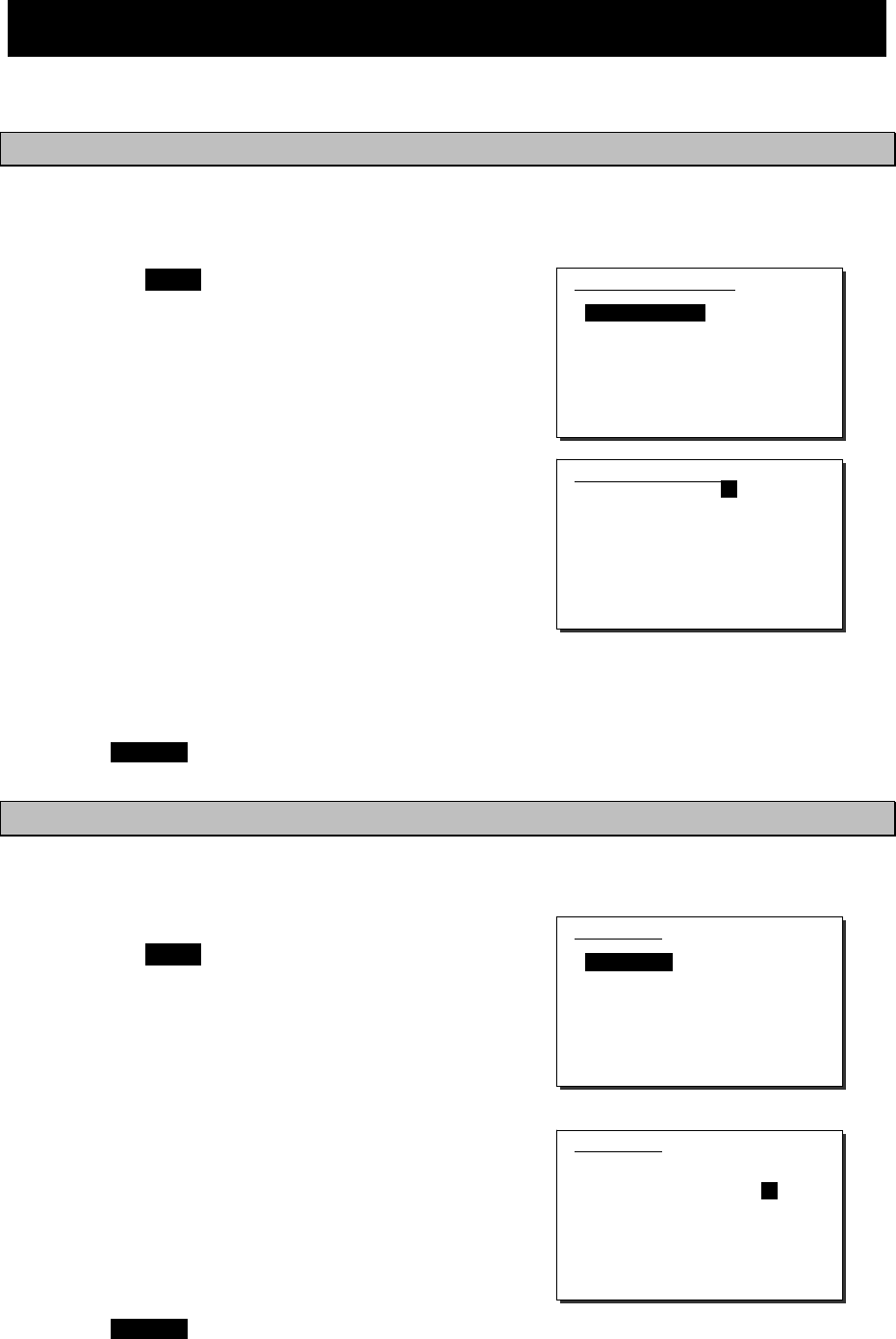
Settings & Registrations
5-4
5.3 Controller settings
The following describes the procedure regarding individual settings for the controller such as LCD
adjustment.
5.3.1 LCD adjustment
The LCD conditions for viewability are adjustable as follows.
■ Procedure ■
1
1
1.
.
.
Press the MENU key, and through
hierarchical menus, select 7.3.1 LCD
adjustment.
The screen as shown at right is displayed.
2
2
2.
.
.
Move the cursor to the desired item and
press ENT. Then alter the settings as
appropriate with the numeric keypad or
jog dial, and press ENT again.
¾ Set each item within the ranges given
below:
Contrast: 1 - 11
Dimmer: 1 - 10
Screen saver: ON/OFF
Timer: 1 - 999 seconds
¾ To close this menu, place the cursor on
any one of the selectable items and press
the CANCEL key.
5.3.2 Sound settings
Sound settings such as the click beep are adjustable as follows.
■ Procedure ■
1
1
1.
.
.
Press the MENU key, and through
hierarchical menus, select 7.3.2 Sound.
The screen as shown at right is displayed.
2
2
2.
.
.
Move the cursor to the desired item and
press ENT. Then set the conditions as
appropriate with the numeric keypad or
jog dial, and press ENT again.
¾ Notification level for a tone can be set
within 1 - 7.
¾ When Sidetone is set to ON, an 800 Hz
tone sounds during keying in.
¾ To close this menu, place the cursor on
any one of the selectable items and press
the CANCEL key.
7.3.1)LCD adjustment
1.Contrast : 06
2.Dimmer
Maximum : 10
Typical : 08
Minimum : 06
3.Screen saver : OFF
Timer(sec): 060
0.Back
7.3.1)LCD adjustment
1.Contrast : 06
2.Dimmer
Maximum : 10
Typical : 08
Minimum : 06
3.Screen saver : OFF
Timer(sec): 060
0.Back
7.3.2)Sound
1.Operation
- Speaker : ON
- Click : ON
2.Notification level: 7
3.Sidetone : ON
0.Back
7.3.2)Sound
1.Operation
- Speaker : ON
- Click : ON
2.Notification level: 7
3.Sidetone : ON
0.Back
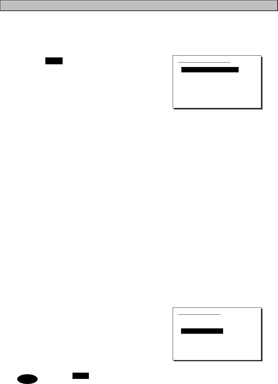
Settings & Registrations
5-5
5.3.3 User key assignments
User key assignment enables the desired menu to be displayed immediately without moving
through the hierarchical menus, and is assignable as follows.
■ Procedure ■
1
1
1.
.
.
Press the MENU key, and through
hierarchical menus, select 7.3.3 User
key assign.
The screen at right is displayed. If the
desired menu has already been registered,
the cursor is placed on that menu.
2
2
2.
.
.
Move the cursor to the desired menu to
be registered with the jog dial.
The assignable menus are as follows:
1.
2.
3.
4.
5.
6.
7.
8.
9.
10.
11.
12.
13.
14.
15.
16.
17.
DSC non-distress call
DSC drobose call
Editing a distress msg
DSC logs
Radio operation
User channel list
ITU channel list
Receiver
Scan
Transmitter
Maintenance
Self diagnosis
DSC loop
Alarm information
Software version
Setup
Date & time
(Menu1)
(Menu2)
(Menu3)
(Menu4)
(Menu5)
(Menu5.1)
(Menu5.2)
(Menu5.4)
(Menu5.4.7)
(Menu5.5)
(Menu6)
(Menu6.1)
(Menu6.1.1)
(Menu6.2)
(Menu6.3)
(Menu7)
(Menu7.1)
18.
19.
20.
21.
22.
23.
24.
25.
26.
27.
28.
29.
30.
31.
32.
33.
POS/TIME
My controller
LCD adjustment
Sound
User channels
DSC/WKR condition
Automatic ACK
WKR scanning FRQ
Option
CH dial lock ON/OFF
2182kHz
AM mode
DSC alarm setting
Group ID
Inactivity timeout
DSC call list
(Menu7.2)
(Menu7.3)
(Menu7.3.1)
(Menu7.3.2)
(Menu7.4)
(Menu7.5)
(Menu7.5.1)
(Menu7.5.2)
(Menu7.6)
---
---
---
(Menu7.3.3)
(Menu7.5.6)
(Menu7.5.7)
(Menu7.5.8)
3
3
3.
.
.
Press ENT to complete registration.
After registration, the screen returns to the
previous hierarchical menu as shown at
right.
When the USER key is pressed in the factory default setting, 7.3 My controller
menu is immediately displayed.
Note
7.3.3)User key assign
1.DSC non-distress call
2.DSC drobose call
3.Editing a distress msg
4.DSC logs
5.Radio operation
6.User channel list
7.ITU channel list
8.Receiver
7.3)My controller
1.LCD adjustment
2.Sound
3.User key assign
4.Tx meter :PWR
5.Data transfer
6.Menu shutdown :10min
7.CH search ref :40
0.Back
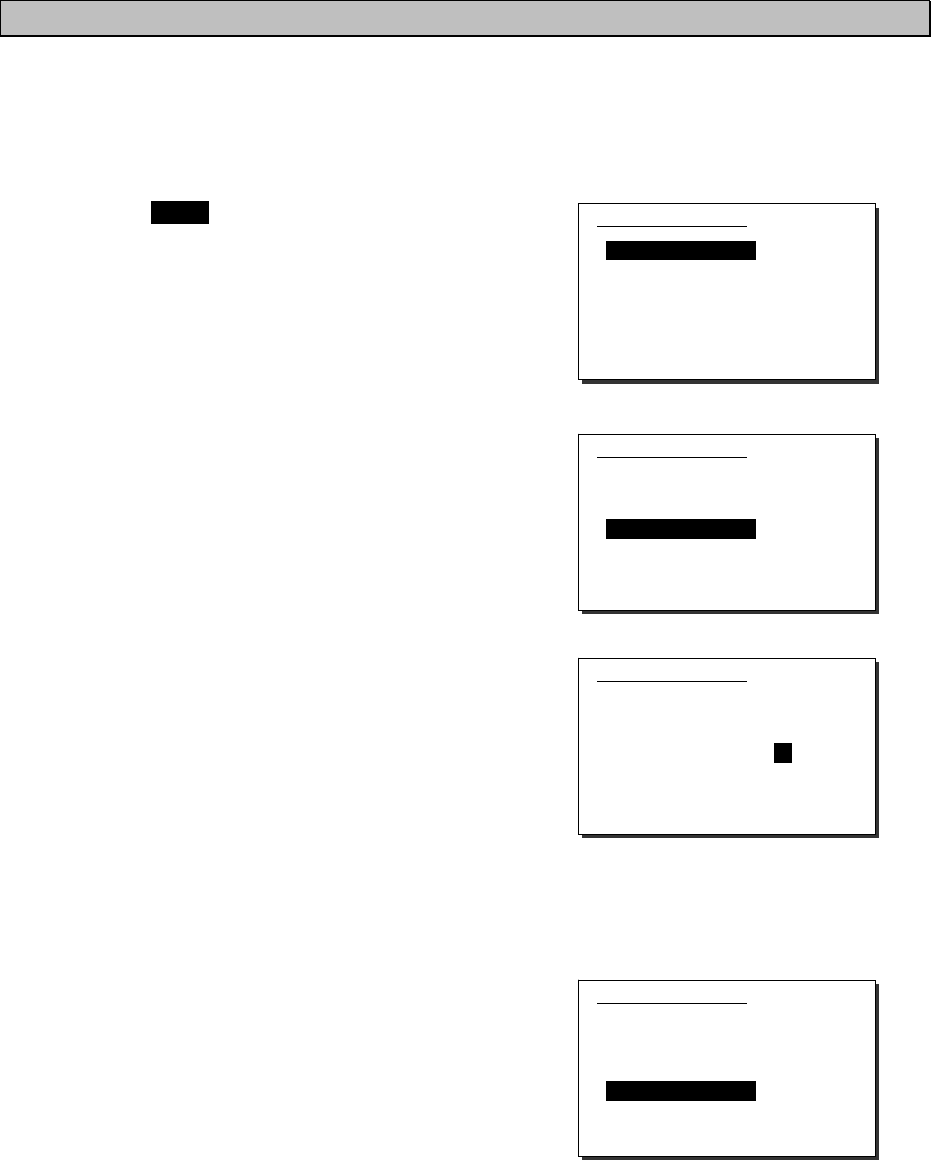
Settings & Registrations
5-6
5.3.4 Selecting Tx meters
The meter displayed in the status display indicates the strength of the received signal (S meter).
However, it can also indicate one of Tx power, antenna current, PA voltage, PA current or key
information during transmission.
■ Procedure ■
1
1
1.
.
.
Press the MENU key, and through
hierarchical menus, select 7.3 My
controller.
The screen as shown at right is displayed.
2
2
2.
.
.
Move the cursor to 4. Tx meter with the
numeric keypad or jog dial.
3
3
3.
.
.
Press ENT, and select the meter type
with the jog dial.
The selectable meters are as follows:
PWR .... Tx power
Ia ........ Antenna current
Vc ....... PA voltage
Ic ........ PA current
Key…….Key information*
* When keying during the ARQ
communication, the Key is indicated
regardless of this setting.
4
4
4.
.
.
Press ENT to confirm the selection.
The setting is complete.
7.3)My controller
1.LCD adjustment
2.Sound
3.User key assign
4.Tx meter :PWR
5.Data transfer
6.Menu shutdown :10min
7.CH search ref :40
0.Back
7.3)My controller
1.LCD adjustment
2.Sound
3.User key assign
4.Tx meter :PWR
5.Data transfer
6.Menu shutdown :10min
7.CH search ref :40
0.Back
7.3)My controller
1.LCD adjustment
2.Sound
3.User key assign
4.Tx meter :Ia
5.Data transfer
6.Menu shutdown :10min
7.CH search ref :40
0.Back
7.3)My controller
1.LCD adjustment
2.Sound
3.User key assign
4.Tx meter :Ia
5.Data transfer
6.Menu shutdown :10min
7.CH search ref :40
0.Back
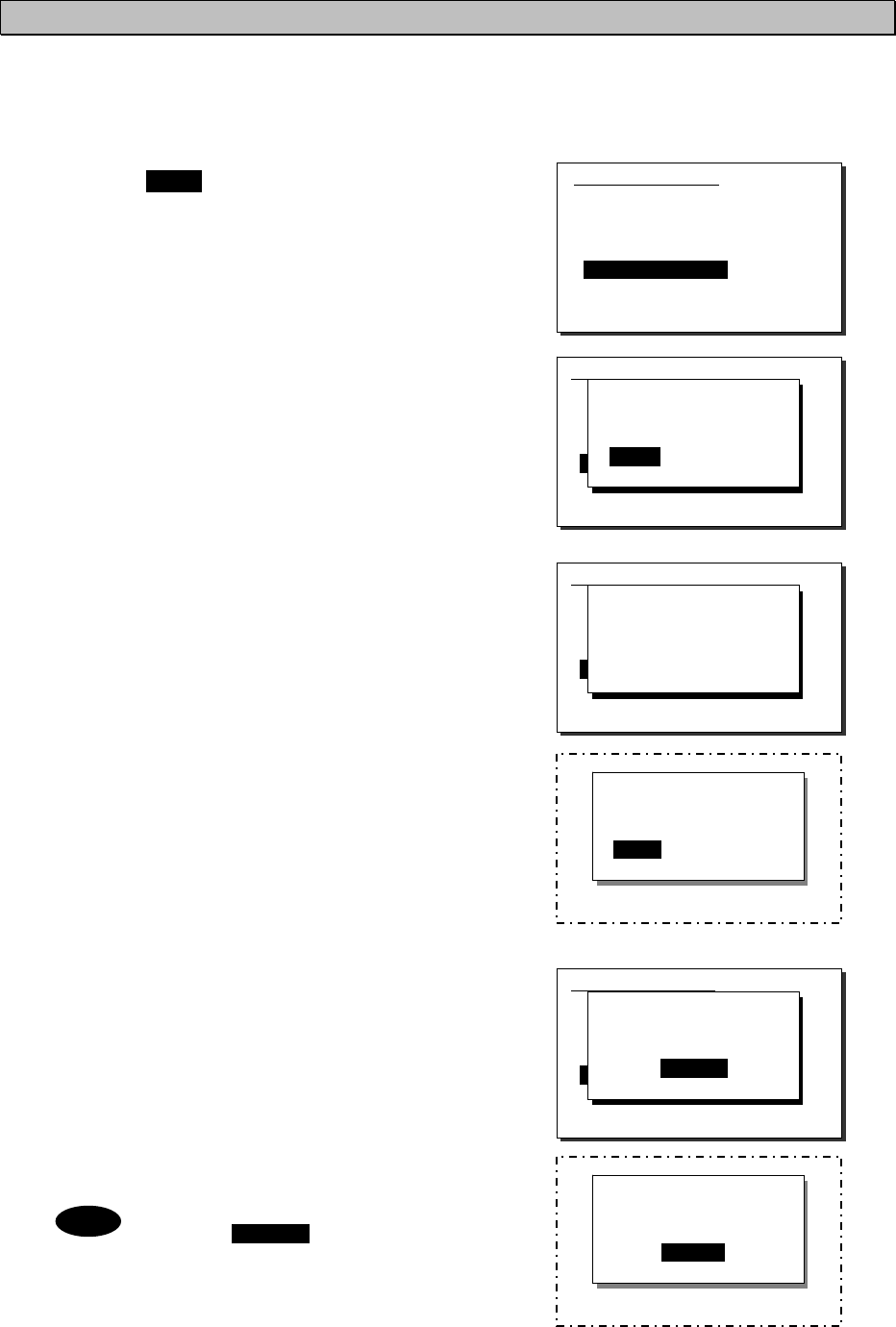
Settings & Registrations
5-7
5.3.5 Transferring user channel data to another controller
When 2 controllers are connected, stored information (user channel table) can be transferred
from the controller having access rights to another controller (monitor condition).
■ Procedure ■
1
1
1.
.
.
Press the MENU key, and through
hierarchical menus, select 7.3 My
controller.
2
2
2.
.
.
Move the cursor to 5. Data transfer with
the numeric keypad or jog dial and press
ENT.
The popup screen as shown at right is
displayed.
3
3
3.
.
.
Press ENT to confirm the selection.
¾ The popup screen as shown at right is
displayed to indicate the controller's
status for forwarding.
¾ The screen at right (below) is displayed
on the monitor.
If OK is selected or the screen is left as
it is for 10 seconds, transferring of
stored information is started.
4
4
4.
.
.
Forwarding of stored information is
started.
¾ During forwarding, the popup screen as
shown at right is displayed.
¾ The screen at right (below) is displayed
on the monitor.
¾ The previous screen is returned to when
forwarding is completed.
To cancel forwarding midway,
press the CANCEL key or ENT.
Note
[Display on monitor]
OK to update this
user channel table?
[ OK ] [Cancel]
[Display on monitor]
Updating the table...
[Cancel]
7.3)My controller
1.LCD adjustment
2.Sound
3.User key assign
4.Tx meter : Ia
5.Data transfer
6.Menu shutdown :10min
7.CH search ref :40
0.Back
OK to transfer the
user channels to
another controller?
[ OK ] [Cancel]
7.3)My controller
1.LCD adjustment
2.Sound
3.User key assign
4.Tx meter : Ia
5.Data transfer
6.Menu shutdown :10min
7.CH search ref :40
0.Back
Wait a moment, please.
7.3)My controller
1.LCD adjustment
2.Sound
3.User key assign
4.Tx meter : Ia
5.Data transfer
6.Menu shutdown :10min
7.CH search ref :40
0.Back
Data sending...
[Cancel]
7.3)My controller
1.LCD adjustment
2.Sound
3.User key assign
4.Tx meter :PWR
5.Data transfer
6.Menu shutdown :10min
7.CH search ref :40
0.Back
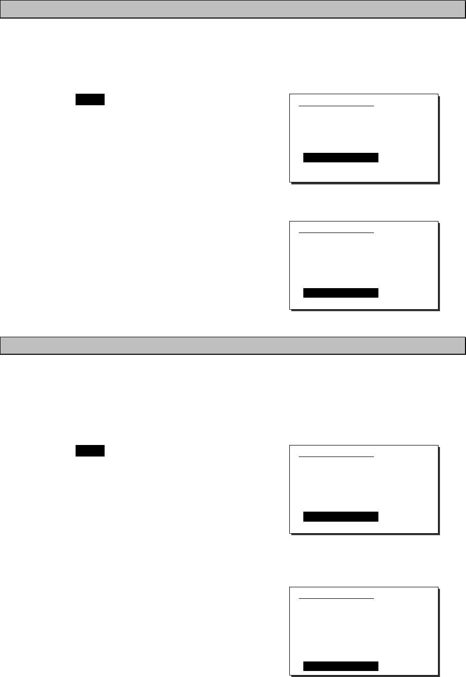
Settings & Registrations
5-8
5.3.6 Setting the inactivity timer (for menu shutdown)
To close menus of the controller automatically which is left as opening menus, the inactivity timer
can be set according to the following procedure.
■ Procedure ■
1
1
1.
.
.
Press the MENU key, and through
hierarchical menus, select 7.3 My
controller.
2
2
2.
.
.
Move the cursor to 6. Menu shutdown
with the numeric keypad or jog dial, and
press ENT.
3
3
3.
.
.
Input the timer value and press ENT.
¾ The range is from 00 to 60 minutes.
¾ To set this timer to OFF, input 00.
In this case, the screen shows OFF as
shown at right.
5.3.7 Setting the reference value for the channel auto search
When making a DSC routine call, the controller searches the working channel (frequency)
automatically by checking the every channel busy referring the signal level with the value set as
follows.
■ Procedure ■
1
1
1.
.
.
Press the MENU key, and through
hierarchical menus, select 7.3 My
controller.
2
2
2.
.
.
Move the cursor to 7. CH search ref with
the numeric keypad or jog dial, and
press ENT.
3
3
3.
.
.
Input the reference value and press ENT.
The range is from 00 to 50.
7.3)My controller
1.LCD adjustment
2.Sound
3.User key assign
4.Tx meter :PWR
5.Data transfer
6.Menu shutdown :10min
7.CH search ref :40
0.Back
7.3)My controller
1.LCD adjustment
2.Sound
3.User key assign
4.Tx meter :PWR
5.Data transfer
6.Menu shutdown :OFF
7.CH search ref :40
0.Back
7.3)My controller
1.LCD adjustment
2.Sound
3.User key assign
4.Tx meter :PWR
5.Data transfer
6.Menu shutdown :10min
7.CH search ref :40
0.Back
7.3)My controller
1.LCD adjustment
2.Sound
3.User key assign
4.Tx meter :PWR
5.Data transfer
6.Menu shutdown :OFF
7.CH search ref :45
0.Back
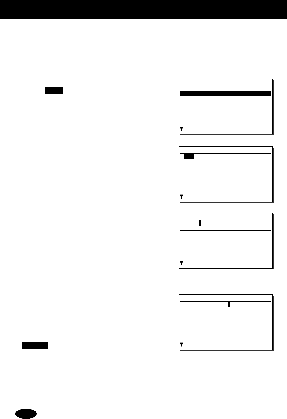
Settings & Registrations
5-9
5.4 Registering user channels
Often used frequencies at the controller for the radiotelephone, CW, and DSC mode can be
registered as user channels and used in scanning radio settings or groups. A total of 20 groups
with 20 channels set to each group (i.e. 400 channels) can be registered. Furthermore, the user
channels of the telex frequency can be registered to the station list of the data terminal.
■ Procedure ■
1
1
1.
.
.
Press the MENU key, and through
hierarchical menus, select 7.4 User
channels (index).
2
2
2.
.
.
Select the desired row or group to be edited
with the numeric keypad or jog dial.
The screen at right is displayed. (This
example is for new registration to group 03.)
Also, if an unregistered group is opened,
TEL is displayed at Type as the default.
3
3
3.
.
.
Press ENT to enter the group name.
¾ Up to 18 characters can be registered.
¾ The following characters are available:
Alphabet (capital and small letters)
Numbers 0 - 9
The following signs, space and
determination symbol (
◄
)
[ ] _ " # % & ' ( ) ? @ + - / = : ; < >
¾ Group names can be omitted.
4
4
4.
.
.
Select a character and press ENT one by
one.
¾ When inputting numbers with the
numeric keypad ENT is not needed.
¾ To return to the previous letter, press the
CANCEL key.
¾ To complete name entry of 18 characters long,
press ENT after selecting the last character by
the jog dial. Or, if the name is less than 18
characters long, following the name, select the
determination symbol (
◄
), as shown at right
and press ENT.
The character sequence shown by turning the jog dial is as follows:
◄
A B C D E F G H I J K L M N O P Q R S T U V W X Y Z a b c d e f g h i j k l m n
o p q r s t u v w x y z [ ] _ " # % & ' ( ) ? @ + - / = : ; < > 0 1 2 3 4 5 6 7 8 9
(space)
Note
7.4)User channels (index)
No CH group name Type
01 JRC Tokyo TEL
02
03
04
05
06
07
08
Pacific ABC CW
7.4)User channels (table)
Name:
Type: TEL
CHNo Rx[kHz] Tx[kHz] Mode
041
042
043
044
045
046
7.4)User channels (table)
Name:
◄
Type: TEL
CHNo Rx[kHz] Tx[kHz] Mode
041
042
043
044
045
046
7.4)User channels (table)
Name: Japan Radio
◄
Type: TEL
CHNo Rx[kHz] Tx[kHz] Mode
041
042
043
044
045
046
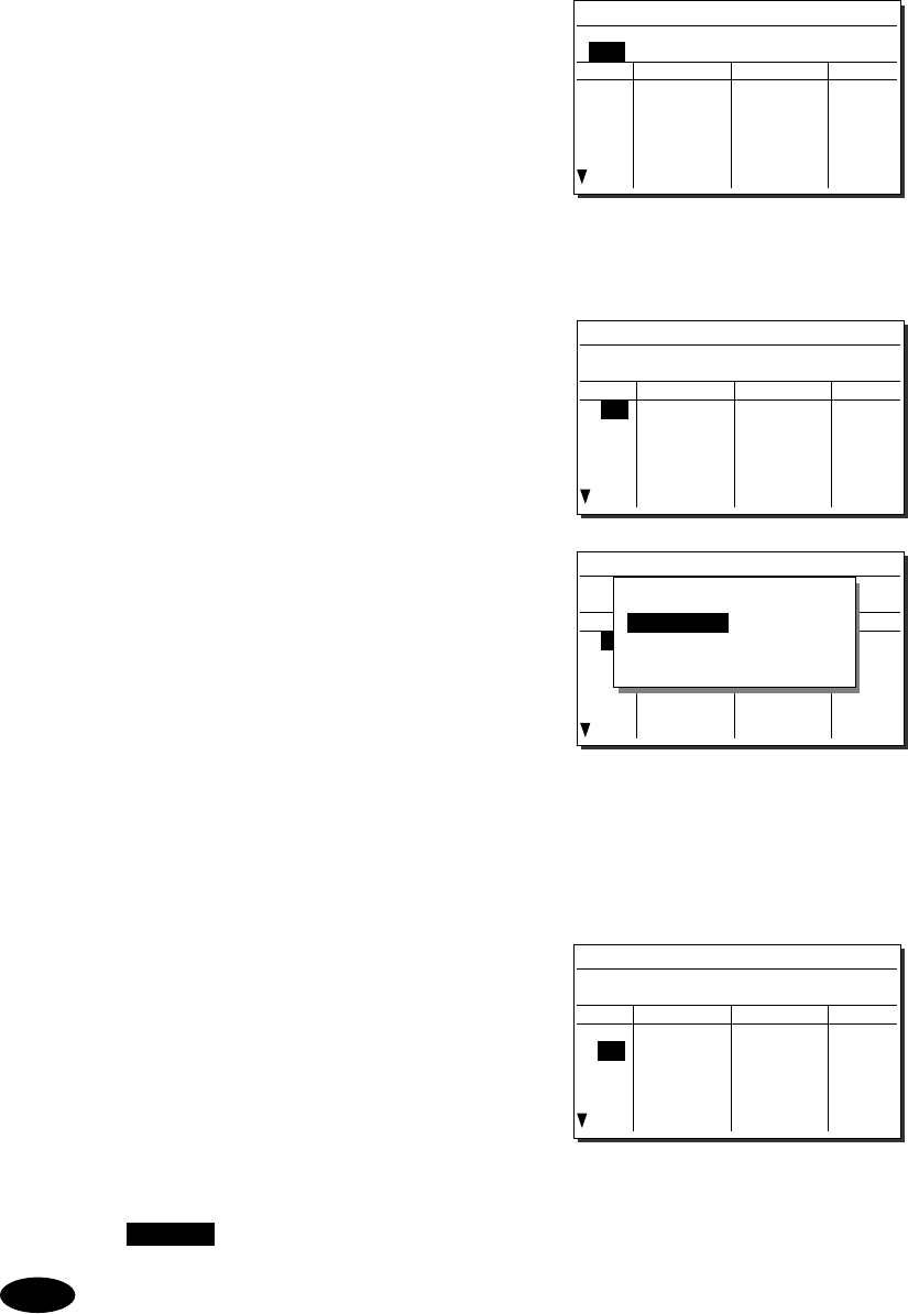
Settings & Registrations
5-10
5
5
5.
.
.
After completing the above steps, the
cursor returns to Type.
¾ If necessary, change the group attribute
(communication mode or custom).
¾ The following attributes can be
selected:
TEL ··········· Radiotelephone mode
DSC ··········· Digital selective calling mode
CW ············ Continuous wave mode
Custom Communication mode mix
6
6
6.
.
.
When setting of group attributes is
completed, the cursor returns to the
topmost row of the channel number.
(CHNo).
7
7
7.
.
.
Select the channel number to register
with the jog dial, and press ENT.
Register as follows in the popup screen at right.
¾ When the group attribute is Custom, specify
the communication mode at Mode.
Otherwise, the communication mode is
fixed to the mode specified at Type.
¾ To reference a frequency from the ITU
channel, move the cursor to ITU channel,
press ENT, and specify that channel number.
¾ Move the cursor to Rx freq(kHz), press
ENT, and enter the Rx frequency.
¾ Move the cursor to Tx freq(kHz), press
ENT, and enter the Tx frequency.
8
8
8.
.
.
After completing the above steps, move
the cursor to OK, and press ENT to
complete registration.
¾ Follow the same procedure above to
create a group of channels.
¾ Already registered channels can be
changed by the above procedure.
¾ To close this menu, place the cursor on
any one of the registration numbers, and
press the CANCEL key.
- To delete an already registered channel, move the cursor to Erase in the
above popup screen, and press ENT.
- To erase an already registered group, move the cursor to "000 ALL CLEAR
function" in the bottommost row of the channel list, and press ENT. Next,
move the cursor to OK in the confirmation screen, and press ENT.
- To erase all already registered groups, move the cursor to "00 ALL CLEAR
function" in the User channels (index) screen, and press ENT. Next, move the
cursor to OK in the confirmation screen, and press ENT.
- When the 7.6.1 Connection is set to DTE, the group 20 becomes the reserved
group for telex channels of the data terminal and inaccessible at the controller.
Note
7.4)User channels (table)
Name: Japan Radio
Type: TEL
CHNo Rx[kHz] Tx[kHz] Mode
041
042
043
044
045
046
7.4)User channels (table)
Name: Japan Radio
Type: TEL
CHNo Rx[kHz] Tx[kHz] Mode
041
042
043
044
045
046
7.4)User channels (table)
Name: Japan Radio
Type: TEL
CHNo Rx[kHz] Tx[kHz] Mode
041
042
043
044
045
046
CHNo. 041/Type TEL
Mode :TEL
ITU Channel :
Rx freq(kHz) :
Tx freq(kHz) :
[OK] [Cancel] [Erase]
7.4)User channels (table)
Name: Japan Radio
Type: TEL
CHNo Rx[kHz] Tx[kHz] Mode
041
042
043
044
045
046
4071.0 4071.0 TEL
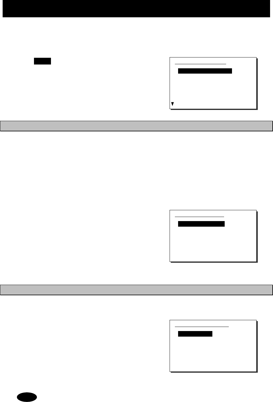
Settings & Registrations
5-11
5.5 Advanced settings for DSC/WKR
The following describes the procedure for the advanced DSC settings such as automatic
acknowledgement, as well as setting the watch frequency of the watch keeping receiver.
■ Menu screen ■
Press the MENU key, and through
hierarchical menus, select 7.5 DSC/WKR
condition.
The following describes the procedures from
this screen. Note that the screen at right
shows factory default settings.
5.5.1 Automatic acknowledgement
While the automatic acknowledgement is set to ON, and no menu is displayed and there is no
active procedure, if either one of the individual calls below is received, the acknowledgement is
sent automatically.
Safety test call
Safety position request call
Routine polling call
Individual call requesting communication without valid frequency (*)
(*) In this case, the “unable to comply” acknowledgement is sent.
■ Procedure ■
1
1
1.
.
.
Move the cursor to 1. Automatic ACK,
and press ENT.
The screen as shown at right is displayed.
2
2
2.
.
.
Set the call setting targeted for
automatic acknowledgement to ON.
5.5.2 Setting DSC watch frequency
Set the frequency to watch on the WKR (DSC watch keeping receiver).
■ Procedure ■
1
1
1.
.
.
Move the cursor to 2. WKR scanning
FRQ, and press ENT.
The screen as shown at right is displayed.
2
2
2.
.
.
Press ENT, and set another frequency in
addition to 2187.5 kHz and 8414.5 kHz to ON.
In accordance with the SOLAS Convention, 2187.5 kHz and 8414.5 kHz cannot be
turned OFF.
7.5)DSC/WKR condition
1.Automatic ACK
2.WKR scanning FRQ
3.DSC alarm setting
4.Medical use :OFF
5.Neutral use :OFF
6.Group ID
7.Inactivity timeout
8.DSC call list
Note
7.5.2)WKR scanning FRQ
1.Registration
- CH1 2187.5kHz :(Const)
- CH2 4207.5kHz :OFF
- CH3 6312.0kHz :ON
- CH4 8414.5kHz :(Const)
- CH5 12577.0kHz :ON
- CH6 16804.5kHz :OFF
0.Back
7.5.1)Automatic ACK
1.Test call :ON
2.Position RQ call :OFF
3.Polling call :ON
4.Individual call :ON
0.Back
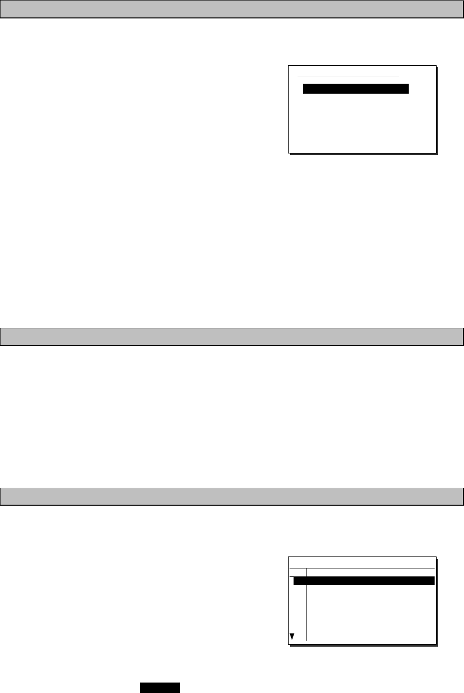
Settings & Registrations
5-12
5.5.3 Setting receiving alarms
The DSC receiving alarm can be set as follows.
■ Procedure ■
Move the cursor to 3. DSC alarm setting, and
press ENT.
The screen as shown at right is displayed.
Change the settings as appropriate.
¾ To disable the receiving alarms for routine
and safety calls, set 1. Safety/Routine RX
ALM to OFF.
¾ The receiving alarms condition of distress alerts or distress relay calls can be changed
using the menu 2. Distress RX ALM as follows.
- Normally when receiving a new distress event, the receiving alarm has to be stopped
manually. However if the ship in distress is located within 70 degree north and 70
degree south latitude, and farther than the Maximum distance value while the Self-
terminating set is ON, the alarm is treated as the self-terminating alarm.
- The Maximum distance can be set within the range of 500 to 999 NM.
Note1) If making this value valid, always set the Self-terminating to ON.
Note2) If receiving DSC messages from the ships located out of range, the messages
are handled normally except the alarm sound.
5.5.4 Using medical/neutral settings for urgency calls
Set the condition so that an urgency area call containing the additional subject of either "Medical
transportation" or "Neutral nationality" can be sent. It is useful for the situation when sailing
dangerous waters such as in areas of political instability, and needed to inform receivers of the
additional information if any of the following apply.
-
Own ship is performing medical transportation and protected under the 1949 Geneva Convention.
-
Own ship is of neutral nationality in accordance with ITU resolution 18 (Mob-83).
Additionally note that this setting is returned to the default (OFF) if the power is turned off.
■ Procedure ■
To use these kinds of calls, set 4. Medical use or 5. Neutral use condition to ON.
5.5.5 Registering the ship's group ID
Register the group ID (group ship ID number) for receiving group calls.
■ Procedure ■
1
1
1.
.
.
Move the cursor to 6. Group ID, and
press ENT.
The screen as shown at right is displayed.
2
2
2.
.
.
Move the cursor to register the ID
number and press ENT, then input the 9
digits ID (leftmost digit fixed to 0).
¾ Upto 20 groups can be registered.
¾ When finished, press CANCEL key.
7.5.3)DSC alarm setting
1.Safety/Routine RX ALM :ON
2.Distress RX ALM
- Maximum distance(NM):500
- Self-terminating :OFF
0.Back
7.5.6)Group ID
No 9-digit ID number
01
02
03
04
05
06
07
08
043100001
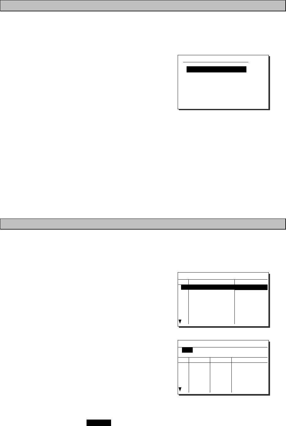
Settings & Registrations
5-13
5.5.6 Setting the inactivity timer (for procedures on hold)
When making a procedure on hold, the procedure is automatically terminated after the time set as
follows.
■ Procedure ■
1
1
1.
.
.
Move the cursor to 7. Inactivity timeout,
and press ENT.
The screen as shown at right is displayed.
Change the settings as appropriate.
1. ACKed distress alert
The acknowledged distress alert events
sent from the own ship:
- The range is 00 (OFF) to 60 minutes.
2. RCVed other distress
The distress events of other ships
- The range is 00 (OFF) to 60 minutes.
3. Non-distress call
Routine, safety and urgency events
- The range is 00 (OFF) to 60 minutes.
4. Other communications
Communications without using DSC
- The range is 010 to 600 seconds.
5.5.7 Registering the DSC call list
To call the station using the DSC, registers the station names, MMSI and the calling frequencies
as follows.
■ Procedure ■
1
1
1.
.
.
Move the cursor to 8. DSC call list, and
press ENT.
The screen as shown at right is displayed.
2
2
2.
.
.
Move the cursor to the line to be
changed and press ENT to display the
frequency list as shown at right.
3
3
3.
.
.
Input data as appropriate using the
numeric keypad or jog dial.
¾ Upto 20 channels for every 20 stations can
be registered.
¾ When finished, press CANCEL key.
7.5.7)Inactivity timeout
1.ACKed distress alert:OFF
2.RCVed other distress:OFF
3.Non-distress call :15min
4.Other communications:030sec
0.Back
7.5.8)DSC call list
No Station name MMSI
01
02
03
04
05
06
07
08
JRC Mitaka1
431000001
7.5.8)DSC call list(FRQ)
Name:JRC Mitaka1
MMSI:431000001
No Rx[kHz] Tx[kHz] Category
01
02
03
04
05
06
2177.0
4219.5
4220.0
4220.5
2189.5
4208.0
4208.5
4209.0
RTN
RTN
RTN
RTN
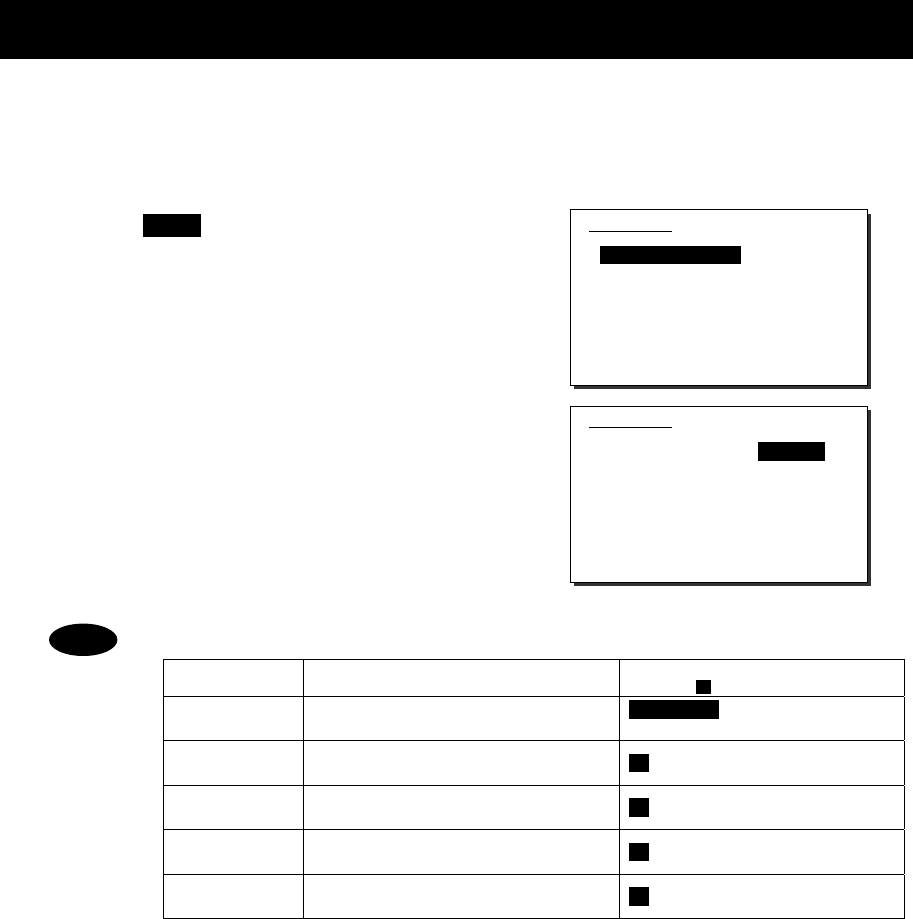
Settings & Registrations
5-14
5.6 Setting connections for options
When setting connections between the controller and optional devices, such as a printer,
configure the conditions as appropriate according to the device type, as follows.
■ Procedure ■
1
1
1.
.
.
Press the MENU key, and through
hierarchical menus, select 7.6 Option.
2
2
2.
.
.
Move the cursor to the desired item, and
press ENT.
Move the cursor to the right. Then select the
condition as appropriate and press ENT.
- The content and the selectable conditions of each item are as follows.
Item Name Content Selectable conditions
( : Factory default)
Connection Connection status and printer type None/CMD/ Serial PRN/
NKG-800/ DTE
Data out Printing method for DSC messages ---/ Auto/ Manual
Baudrate Transmission speed to printer ---/ 4.8k/ 9.6k/ 38.4k/ 57.6kbps
Flow control Handshake setting with printer ---/ None/ Hard
Print direction Printing sequence of lines ---/ Upright/ Invert
- When connecting a serial printer (e.g. NKG-91), set the items as follows:
1.Connection :Serial PRN
2.Data out :Auto
3.Baudrate :4.8k
4.Flow control :Hard
5.Print direction :Invert (NKG-91)/Upright (DPU-414)
- When connecting the NKG-800 printer, set the items as follows:
1.Connection :NKG-800
2.Data out :Auto
- If no option is connected, select None/CMD at the Connection.
Note) When None/CMD is set, connect nothing to the serial port.
- When connecting the data terminal to the controller for the telex communication,
set Connection item to DTE. Note that restart the system just after this setting.
Moreover, Baudrate, Flow control and Print direction become unchangeable in
this case.
Note
7.6)Option
1.Connection :None/CMD
2.Data out :---
3.Baudrate :---
4.Flow control :---
5.Print direction :---
0.Back
7.6)Option
1.Connection :None/CMD
2.Data out :---
3.Baudrate :---
4.Flow control :---
5.Print direction :---
0.Back
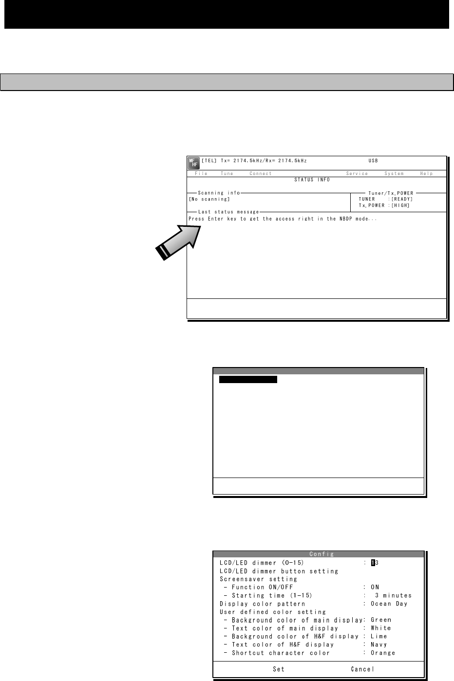
Settings & Registrations
5-15
5.7 Setting of data terminal
The following describes the procedure regarding LCD adjustment, such as the color settings and
brightness, and registration of the station list.
5.7.1 LCD adjustment
■ Procedure ■
1
1
1.
.
.
If displaying the message of "Press Enter key to get the access right in the NBDP
mode…" on the data terminal, press Enter key on the keyboard.
The operation of the data
terminal becomes possible in
the telex mode, except when
the controller is used.
2
2
2.
.
.
On the main menu and the dropdown menu, select System Î Config with Enter key.
The setting conditions
concerning to the screen are
displayed.
3
3
3.
.
.
Select the item to be changed by the cursor and press Enter key, then input the
appropriate condition.
Set the item using the numeric
keypad or dropdown menu,
where the cursor moves to the
right as shown at right. As for
other items, the specific menu
is displayed.
Config
LCD/LED dimmer (0-15) : 13
LCD/LED dimmer button setting
Screensaver setting
- Function ON/OFF : ON
- Starting time (1-15) : 3 minutes
Display color pattern : Ocean Day
User defined color setting
- Background color of main display: Green
- Text color of main display : White
- Background color of H&F display : Lime
- Text color of H&F display : Navy
- Shortcut character color : Orange
Set Cancel
LCD/LED dimmer

Settings & Registrations
5-16
4
4
4.
.
.
When completing the setting, move the cursor to the Set and press Enter key.
The content of each setting item is as follows.
Item Content of setting Remarks
LCD/LED dimmer (0-15) Adjusts the brightness of the LCD
and the panel lamp by 16 steps.
Without using this menu,
the dimmer is adjustable
with Ctrl+Ç or Ctrl+È
operation.
LCD/LED dimmer button setting
Sets the brightness of the LCD and
the panel lamp when using the DIM
key on the panel.
Screensaver setting
- Function ON/OFF Sets the screen saver ON/OFF.
- Starting time (1-15) Sets the time until the screensaver
starts.
The screensaver is invalid
at the following cases;
・ communicating in the
telex mode,
・ running self-diagnosis.
Display color pattern
Sets the color of the screen from the
following 9 patterns of the dropdown
list.
- Ocean Day/ Dusk/ Night
- Earth Day/ Dusk/ Night
- Basic Black/ White
- User defined
User defined color setting
-
Background color of main display
Sets the background color of the
main screen from the following.
Black/ Gray/ Silver/ White/ Maroon/
Red/ Olive/ Yellow/ Green/ Lime/
Teal/ Cyan/ Navy/ Blue/ Purple/
Magenta/ Orange
・ This menu is valid only
when Display color
pattern = User defined.
・ Setting the same color
with the main screen
or the short cut
character is inhibited.
- Text color of main display
Sets the text color of the main
screen from the following.
Black/ Gray/ Silver/ White/ Maroon/
Red/ Olive/ Yellow/ Green/ Lime/
Teal/ Cyan/ Navy/ Blue/ Purple/
Magenta/ Orange
・ This menu is valid only
when Display color
pattern = User defined.
・ Setting the same color
with the background of
the main screen is
inhibited.
-
Background color of H&F display
Sets the background color of the
header/footer screen from the
following.
Black/ Gray/ Silver/ White/ Maroon/
Red/ Olive/ Yellow/ Green/ Lime/
Teal/ Cyan/ Navy/ Blue/ Purple/
Magenta/ Orange
・ This menu is valid only
when Display color
pattern = User defined.
・ Setting the same color
with the text of the
header/footer screen is
inhibited.
- Text color of H&F display
Sets the text color of the header/
footer screen from the following.
Black/ Gray/ Silver/ White/ Maroon/
Red/ Olive/ Yellow/ Green/ Lime/
Teal/ Cyan/ Navy/ Blue/ Purple/
Magenta/ Orange
・ This menu is valid only
when Display color
pattern = User defined.
・ Setting the same color
with the background of
the header/footer
screen is inhibited.
- Shortcut character color
Sets the shortcut character color
from the following.
Black/ Gray/ Silver/ White/ Maroon/
Red/ Olive/ Yellow/ Green/ Lime/
Teal/ Cyan/ Navy/ Blue/ Purple/
Magenta/ Orange
・ This menu is valid only
when Display color
pattern = User defined.
・ Setting the same color
with the background of
the main screen is
inhibited.
Note
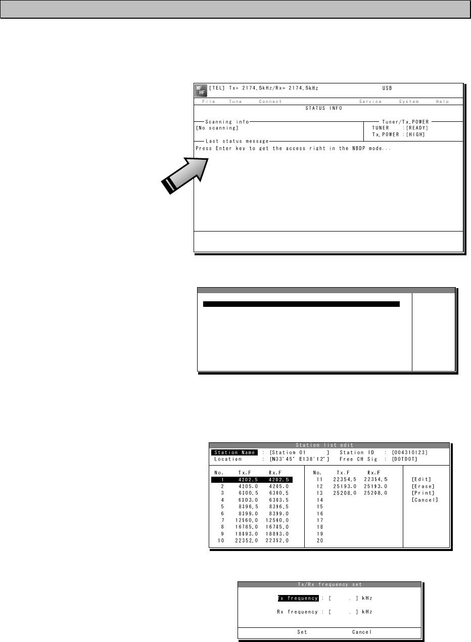
Settings & Registrations
5-17
5.7.2 Registering station list
■ Procedure ■
1
1
1.
.
.
If displaying the message of "Press Enter key to get the access right in the NBDP
mode…" on the data terminal, press Enter key on the keyboard.
The operation of the data
terminal becomes possible in
the telex mode, except when
the controller is used.
2
2
2.
.
.
On the main menu and the dropdown menu, select Service Î Station list with Enter
key.
The station list is displayed.
3
3
3.
.
.
Select the line to be registered newly or to be changed with the cursor and press
Enter key. Then input the station information including the channels on the station list
edit screen.
¾ Input the radio station name
within 16 characters to Station
Name column.
(The @ character is unavailable.)
¾ Input 4 (coast station), 5 (ships
station) or 9 digits SELCAL
number to Station ID column.
¾ The Location and Free CH Sig
are optional.
¾ Move the cursor to the line to
be registered and press Enter
key. Then input the Tx/Rx
frequencies on the popup
screen at right.
4
4
4.
.
.
After inputting, press Enter key to close the screen and finish the registration.
Station list
No. Station Name ID Location F.Sig
1 Station 01 004310123 N33゚45' E138゚12' DOTDOT [Edit]
2 Station 02 004311234 N37゚22' E135゚51' DOTDOT [Erase]
3 Station 03 431012345 [Print]
4 [Cancel]
5
6
7
8
9
10 ↓
1 Station 01 004310123 N33゚45' E138゚12' DOTDOT

Settings & Registrations
5-18
There is the station database menu (Service Î Station database) as a similar
registration menu to register the station information. The station database
operation is basically the same with the station list. However note that the station
list is designed for the manual input only, but the station database is designed to
register the station information more easily such as copying the original station
database prepared in advance. The functions available on the station database
screen are as follows.
・ Program ·············· Registers the station information located with the
cursor to the desired line of the station list.
・ Read ··················· Reads the station database saved in the flash ROM or
the USB memory.
・ Write ··················· Saves the prepared station database in another drive or
the folder.
・ Get ····················· Loads station information of the station list on a line of
the station database.
Note
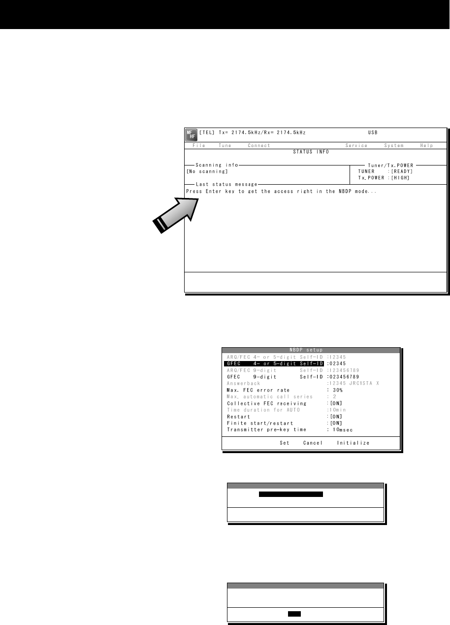
Settings & Registrations
5-19
5.8 Setting telex mode
The following describes the procedure to check or set the condition for the telex communication.
■ Procedure ■
1
1
1.
.
.
If displaying the message of "Press Enter key to get the access right in the NBDP
mode…" on the data terminal, press Enter key on the keyboard.
The operation of the data
terminal becomes possible in
the telex mode, except when
the controller is used.
2
2
2.
.
.
On the main menu and the dropdown menu, select System Î NBDP setup with Enter
key.
The setting conditions
concerning to the telex
communication are displayed.
3
3
3.
.
.
Select the item to be changed with the cursor, and press Enter key.
The input screen as shown at right is
displayed.
※ An example of Max. FEC error rate
4
4
4.
.
.
Press Enter key to move the cursor to the right. Then input the value and press Enter
key again.
The cursor moves to Set.
Setup data input
Max. FEC error rate : [ 30] %
Input range is from 1 to 100.
Set Cancel
Max. FEC error rate
Setup data input
Max. FEC error rate : [ 30] %
Input range is from 1 to 100.
Set Cancel
Set

Settings & Registrations
5-20
5
5
5.
.
.
When the cursor is located on Set, press Enter key to set the value and close the
popup screen.
6
6
6.
.
.
After completing the every input, move the cursor to Set and press Enter key to save
and finish the registration.
- When selecting the Initialize with the cursor and pressing Enter key, the every
accessible item is reset to the factory default setting.
- The content of each item and the factory default setting values are as follows.
Item Setting contents
Initial
value Remarks
ARQ/FEC 4- or 5-digit Self-ID Registers the SELCAL number.
※ 4-digit is for the coast station. -----
When setting this item,
contact our company or
agency.
GFEC 4- or 5-digit Self-ID Registers the group ID.
※ 4-digit is for the coast station -----
ARQ/FEC 9-digit Self-ID 9-digit SELCAL number for
reference. ----- Common with the DSC
GFEC 9-digit Self-ID Registers the 9-digit group ID. -----
Answerback Registers the answerback code
used with WRU and Hereis. -----
When setting this item,
contact our company or
agency.
Max. FEC error rate Sets the permissible error rate that
occurs during CFEC receiving. 30 %
Max. automatic call series
Sets times to retry calling a station
if failed to call the station using the
CALL function.
2 Optional
Collective FEC receiving Sets ON/OFF of the CFEC or SFEC
receiving. ON
Time duration for AUTO
Sets the interval time until retrying
if failed to call a coast station using
the AUTOTELEX function.
10 min Optional
Restart
Sets ON/OFF of the rephasing
function if disconnected the
communication in ARQ mode.
ON
Finite start/restart
Sets ON/OFF of the limit of the
ARQ call times, which is 128 times
for phasing and 32 times for
rephasing.
ON
Transmitter pre-key time Sets a period between key on and
starting the signal output. 10 ms
Note

Maintenance & Inspection
6-1
6. MAINTENANCE & INSPECTION
The performance and lifetime of the equipment depend on appropriate maintenance. This
chapter describes an outline of maintenance and inspection, self diagnosis and
troubleshooting.
6.1 General maintenance & inspection
In order to operate the equipment under optimum conditions, it is vital to perform regular
inspections and also, to keep accurate records. Inspections enable problems to be identified
before they become major malfunctions. The following inspections should be made regularly.
Inspection
sequence Inspection item Procedure
1 Antenna system Check that antennas and the connectors are secure.
2 RF GAIN function
In the radiotelephone mode (TEL), turn the RF GAIN
control on the controller having access rights. Is the
radio static (noise) from the speaker adjustable?
3 Receiver condition
check by speaker output
Check that the voice level and noise level are not
abnormally loud or soft.
4 Handset PTT switch
In the radiotelephone (TEL) mode, press the PTT
switch, and check that the unit transmits immediately
on the Tx meter or by TX and ON displayed on the
screen.
5
Transmission and
reception check by
performing radio
communication
In the radiotelephone (TEL) mode, check that normal
conversation is possible.
6 Condition of the data
terminal
When the communication mode is other than the telex
mode (e.g. TEL mode), check that the communication
mode can be set to the telex mode by pressing the
Enter key on the keyboard of the data terminal.
7 Air filter Check that if the air filters of the power supply and/or
the battery charger are clogged with dust.
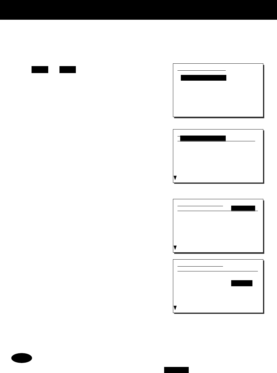
Maintenance & Inspection
6-2
6.2 Self diagnosis inspection
The following describes the procedure for performing self diagnosis in the 6.1 Self diagnosis
menu.
■ Procedure ■
1
1
1.
.
.
Press FUNC Î 8TEST .
The 6.1 Self diagnosis menu is displayed.
2
2
2.
.
.
Select Transceiver, Controller/DTE, or
DSC/NBDP loop.
¾ When Transceiver is selected, the screen
at right is displayed.
¾ For DSC/NBDP loop, a shortcut menu for
diagnosing the modem is as shown in the
screen at right.
3
3
3.
.
.
In the above screen, press ENT, select
the diagnosis mode with the jog dial, and
press ENT. Self diagnosis is performed.
The following test modes are available:
6.1.1) Transceiver ........ ALL (all modes)
TRX&MODEM
PA&ATU
WKR MODEM
TRX
PA
ATU
6.1.2) Controller/DTE ... ALL (all modes)
DGT CKT
AF output
LCD&LED
Speaker
Printer
DTE
- If the jog dial is turned while the cursor is at Target when Transceiver is selected,
the diagnosis items of each unit and previous diagnosis results can be browsed.
- To cancel self diagnosis midway, press the CANCEL key.
- The results of the self diagnosis are stored as a log, and up to 10 logs can be
confirmed from the 6.1.3 Transceiver log or 6.1.4 Controller/DTE log menu.
- The self diagnosis results are printed out on the connected printer as the factory
default setting. However note that the print format is selectable from Valid (the
target name and the results of diagnosis items), Simple (the target name and the
result), and Invalid (Not print) using the menu 6.1.1 Printout.
- The self diagnosis test contents and results are as shown below. However note
that if PA and/or ATU is in below freezing conditions, to avoid the failure of the
moving part, the FAN is not checked and “-“(hyphen) is shown as the result.
Note
6.1.1)Transceiver
Target :ALL
- ATU -
1.Serial I/F :
2.RBK port :
3.Band1 input :
4.Band1 tune :
5.Band2 input :
6.Band2 tune :
7.Band3 input :
6.1)Self diagnosis
1.Transceiver
2.Controller/DTE
3.Transceiver log
4.Controller/DTE log
5.DSC/NBDP loop
6.Printout :Valid
0.Back
6.1.1)Transceiver
Target :TRX&MODEM
- ATU -
1.Serial I/F :
2.RBK port :
3.Band1 input :
4.Band1 tune :
5.Band2 input :
6.Band2 tune :
7.Band3 input :
6.1.1)Transceiver
Target :ATU
- ATU -
1.Serial I/F :OK
2.RBK port :Checking
3.Band1 input :
4.Band1 tune :
5.Band2 input :
6.Band2 tune :
7.Band3 input :

Maintenance & Inspection
6-3
Unit Name Test Item Contents Results
Transceiver
ATU
x Serial I/F :Serial communication
x RBK port :RBK interface
x Band1 input :2140 kHz input value
x Band1 tune :2140 kHz tuning operation
x Band2 input :4149 kHz input value
x Band2 tune :4149 kHz tuning operation
x Band3 input :6230 kHz input value
x Band3 tune :6230 kHz tuning operation
x Band4 input :8297 kHz input value
x Band4 tune :8297 kHz tuning operation
x Band5 input :16546 kHz input value
x Band5 tune :16546 kHz tuning operation
x Band6 input :25118 kHz input value
x Band6 tune :25118 kHz tuning operation
x Fan :Air cooling fan operation
OK: Normal
NG: Abnormal
PA
x PA mute port :Confirmation of PA diagnosis
viability
x RBK port :RBK overcurrent detection
x Memory1 :EEPROM1 operation
x Memory2 :EEPROM2 operation
x PA(A) voltage :PA (A) PS voltage
x PA(B) voltage :PA (B) PS voltage *
x DA output :2140 kHz output from DA
x PA(A) bias :PA (A) idling current
x PA(A) output :PA (A) output
x PA(B) bias :PA (B) idling current *
x PA(B) output :PA (B) output *
x
PA(A)+(B) output
:Combined PA output *
x
LPF band1 output
:2140kHz output
x
LPF band2 output
:3023kHz output
x
LPF band3 output
:4149kHz output
x
LPF band4 output
:6230kHz output
x
LPF band5 output
:8297kHz output
x
LPF band6 output
:12365kHz output
x
LPF band7 output
:16546kHz output
x
LPF band8 output
:25118kHz output
x Fan1 : Air cooling fan1 operation
x Fan2 : Air cooling fan2 operation *
x Fan3 : Air cooling fan3 operation
OK: Normal
NG: Abnormal
*
500W model only
TRX
x Memory :EEPROM operation
x Digital CKT :FPGA operation
x BK port :BK signal state
x PLL lock :State of PLL for DDS/DUC
clock
x
Band1-TX output
:1600 kHz output
x
Band2-TX output
:22000 kHz output
x
Band3-TX output
:27500 kHz output
x
Band4-TX output
:RX diagnosis circuit
x
Band1-RX BPF1
:1600 kHz Rx level
x
Band2-RX BPF2
:390 kHz Rx level
x
Band3-RX BPF3
:1590 kHz Rx level
x
Band4-RX BPF4
:3190 kHz Rx level
x
Band5-RX BPF5
:6090 kHz Rx level
x
Band6-RX BPF6
:10490 kHz Rx level
x
Band7-RX BPF7
:17990 kHz Rx level
x
Band8-RX BPF8
:27500 kHz Rx level
OK: Normal
NG: Abnormal

Maintenance & Inspection
6-4
Transceiver
(Cont’d)
WKR
MODEM
x Memory1 :FROM operation
x Memory2 :EEPROM operation
x Memory3 :SDRAM operation
x PLL lock :State of PLL for DDS clock
x
Band1-RX BPF1
:2187.5 kHz DSC loop
x
Band2-RX BPF2
:4207.5 kHz DSC loop
x
Band3-RX BPF3
:6312.0 kHz DSC loop
x
Band4-RX BPF4
:8414.5 kHz DSC loop
x
Band5-RX BPF5
:12577.0 kHz DSC loop
x
Band6-RX BPF6
:16804.5 kHz DSC loop
x
Band7-RX BPF7
:Wide-band filter operation
x
DSC/NBDP loop1
:AF modem loop
x
DSC/NBDP loop2
:AF modem & TRX loop
OK: Normal
NG: Abnormal
Unit Name Test Item Contents Results
Controller/
Data terminal
DGT CKT
x Memory1 :FROM operation
x Memory2 :EEPROM operation
x Memory3 :SDRAM operation
OK: Normal
NG: Abnormal
AF output AF connection to TRX OK: Normal
NG: Abnormal
LCD&LED
Screen and ALM lamp display operation
Note: Check visually if every dot and red and
green ALM lamp alternately work normally
for 3 seconds.
DONE
Speaker
Sound test
Note: Check if the 1500 Hz tone sounds correctly.
After that, press ENT on the popup screen
to finish this process.
DONE
Printer
Print out test
Note: When the printer is connected, check the
print result in the printed data output.
DONE
DTE
・ DTE memory1 :FROM operation
・ DTE memory2 :SDRAM operation
OK: Normal
NG: Abnormal
・ DTE LCD&LED :Data terminal screen and
lamp operation
Note: Check visually if every dot alternating colors
of red, green, blue and white with the lamp
blink work normally for 5 seconds.
DONE
・ DTE buzzer :DTE buzzer operation
Note: Check if the buzzer sounds correctly. After 3
seconds, sounding stops automatically
DONE
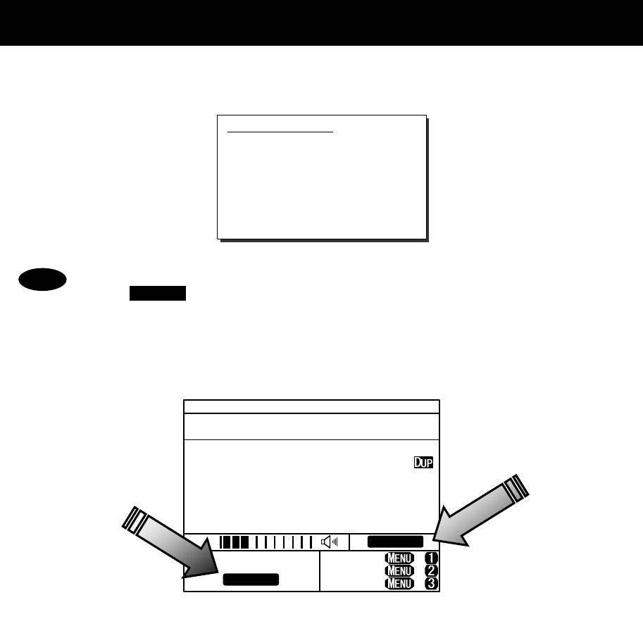
Maintenance & Inspection
6-5
6.3 System alarm indication
This equipment displays alarms as follows when an internal or external error is detected.
- To return to the previous screen after the alarm is displayed, press the
CANCEL key.
- When the TRX 024.PLL unlock or WKR MODEM 030.PLL unlock alarm is
occurring, that mark remains as shown below until the equipment is restored
to normal conditions.
Alarm information
PA :001,Overcurrent(A)
PA :008,High-temp
TEL ITU- 401
4357.0
4065.0
RX kHz
TX kHz
NonDST: +
DROBOS: +
EdtDST: +
ID 431001234 23:59(UTC)
Pos 89゚59.0123'N
179゚59.6789'E@23:59 (EXT)
SIG
WKR scan bands:
Unlock
Unlock
Note

Maintenance & Inspection
6-6
6.3.1 Alarm list
The following list shows the types of system alarms and contents when an alarm is detected on
the equipment.
(*) 500W model only
Alarm
Number
Source
Unit Display Contents Troubleshooting
Procedure
001 PA Overcurrent (A)
Detected an overcurrent (6.8A at
AC, or 5.1A at DC) in the PA(A).
Re-tune or operate on
another frequency.
002 PA Overload (A) Detected the condition SWR > 3 in
the PA(A).
Re-tune or operate on
another frequency.
003 PA Overcurrent (B) * Detected an overcurrent (6.8A at
AC, or 5.1A at DC) in the PA(B).
Re-tune or operate on
another frequency.
004 PA Overload (B) *
Detected the condition SWR > 3 in
the PA(B).
Re-tune or operate on
another frequency.
007 PA SWR/Overload
Detected the condition SWR > 3 or
overload at the PA output.
Re-tune or operate on
another frequency.
008 PA
High-temp On TX, detected high temp (99°C or
more) at the radiator in the PA unit.
Stop transmission, or
reduce output.
010 PA RBK overcurrent Detected RBK overcurrent. Please contact JRC or
our agency.
011 PA High-VDD (A)
Detected overvoltage (132V or more)
at the drain of the FET in the PA(A).
Please contact JRC or
our agency.
012 PA Low-VDD (A) Detected low voltage (80V or less)
at the drain of the PA(A) FET.
Please contact JRC or
our agency.
013 PA High-VDD (B) *
Detected overvoltage (132V or more)
at the drain of the FET in the PA(B).
Please contact JRC or
our agency.
014 PA Low-VDD (B) * Detected low voltage (80V or less)
at the drain of the PA(B) FET.
Please contact JRC or
our agency.
066 PA DA high-temp
Detected high temperature (95°C or
more) at the radiator of the DA.
Stop transmission, or
reduce output.
067 PA
High-temp (A) Detected high temperature (99°C or
more) at the radiator of the PA(A).
Stop transmission, or
reduce output.
068 PA
High-temp (B) * Detected high temperature (99°C or
more) at the radiator of the PA(B).
Stop transmission, or
reduce output.
070 PA EEPROM (PA) Detected the PA memory error. Please contact JRC or
our agency.
091 PA
EEPROM
(PACONT)
Detected a memory error at the PA
CONTROL UNIT.
Please contact JRC or
our agency.
071 PS PS for PA Detected abnormal condition (high
temp/voltage) of the PS for PA.
Please contact JRC or
our agency.
017 ATU ATU lost Detected a serial communication
error with the tuner.
Please contact JRC or
our agency.
018 ATU High voltage Detected a high voltage (3.5 kV or
more) in antenna output.
Re-tune, or reduce
output.
019 ATU High-temp Detected an out-of-range temperature
(70°C or more) inside the enclosure.
Stop transmission, or
reduce output.
072 ATU Overcurrent Detected an overcurrent at the
antenna.
Re-tune, or reduce
output.
020 TRX DISP_KEY
Detected abnormal ON signal at the
PTT or Ext key of the controller.
Please contact JRC or
our agency.
021 TRX EXT_KEY Detected abnormal ON signal at the
transceiver external key.
Please contact JRC or
our agency.
022 TRX SEL_BK Detected abnormal ON signal at
the Selcall key on the transceiver.
Please contact JRC or
our agency.
023 TRX -BK Detected the -BK output error
during transmission.
Please contact JRC or
our agency.
024 TRX PLL unlock Detected PLL unlock for the DDS
or DUC clock.
Please contact JRC or
our agency.
030 WKR
MODEM PLL unlock Detected PLL unlock for the DDS
clock.
Please contact JRC or
our agency.
031 WKR
MODEM MCDSP WDT Detected MCDSP malfunction. Please contact JRC or
our agency.
032 WKR
MODEM VDSP WDT Detected VDSP malfunction. Please contact JRC or
our agency.

Maintenance & Inspection
6-7
033 WKR
MODEM MMSI lost Detected non-registration or loss
of the ship's MMSI.
Please contact JRC or
our agency.
094 WKR
MODEM Memory Detected a memory error. Please contact JRC or
our agency.
035 Controller CTRL1 RBK OC Detected an overcurrent on the
RBK circuit of controller 1.
Please contact JRC or
our agency.
036 Controller CTRL1 PTT Detected an error on the PTT control
line of controller 1.
Please contact JRC or
our agency.
037 Controller CTRL1 CW KEY Detected an error on the CW key control
line of controller 1.
Please contact JRC or
our agency.
038 Controller CTRL1 EXT KEY Detected an error on the external key
control line of controller 1.
Please contact JRC or
our agency.
039 Controller CTRL2 RBK OC Detected an overcurrent on the
RBK circuit of controller 2.
Please contact JRC or
our agency.
040 Controller CTRL2 PTT Detected an error on the PTT control
line of controller 2.
Please contact JRC or
our agency.
041 Controller CTRL2 CW KEY Detected an error on the CW key control
line of controller 2.
Please contact JRC or
our agency.
042 Controller CTRL2 EXT KEY Detected an error on the external key
control line of controller 2.
Please contact JRC or
our agency.
047 Controller PA lost Detected a serial communication
error with the PA.
Please contact JRC or
our agency.
048 Controller TRX lost Detected a serial communication
error with the TRX.
Please contact JRC or
our agency.
050 Controller MODEM lost Detected a serial communication
error with the WKR MODEM.
Please contact JRC or
our agency.
051 Controller CTRL1 lost Detected a serial communication
error with the No.1 controller.
Please contact JRC or
our agency.
052 Controller CTRL2 lost Detected a serial communication
error with the No.2 controller.
Please contact JRC or
our agency.
095 Controller CTRL1 memory Detected a memory error on the
No.1 controller.
Please contact JRC or
our agency.
096 Controller CTRL2 memory Detected a memory error on the
No.2 controller.
Please contact JRC or
our agency.
059 Data
terminal My/OTH DTE lost
Detected a serial communication
error between controller (ID:1)
and DTE.
Note) My or OTH indicates the
relationship between that data
terminal and the controller
displaying this alarm.
Check the data
terminal cable
connection, or the
condition of the data
terminal.
060 Data
terminal My/OTH DTE lost
Detected a serial communication
error between controller (ID:2)
and DTE.
Note) My or OTH indicates the
relationship between that data
terminal and the controller
displaying this alarm.
Check the data
terminal cable
connection, or the
condition of the data
terminal.
062 Data
terminal
My/OTH DTE
USB-IC
Detected the SPI communication
error at the USB circuit of the
data terminal connected to the
controller (ID:1).
Note) My or OTH indicates the
relationship between that data
terminal and the controller
displaying this alarm.
Please contact JRC or
our agency.
063 Data
terminal
My/OTH DTE
USB-IC
Detected the SPI communication
error at the USB circuit of the
data terminal connected to the
controller (ID:2).
Note) My or OTH indicates the
relationship between that data
terminal and the controller
displaying this alarm.
Please contact JRC or
our agency.

Maintenance & Inspection
6-8
Also, the following alarms are displayed when an error is detected just after turning on the
equipment. Please notify JRC or our agency of the details of the alarm.
Display Contents
Detected this controller's barcode number lost!
So required to replace the CONTROL UNIT in it
with the new one.
Detected an error in the barcode number on the
controller.
Detected this controller's SIO error!
So required initial set after restarting as the
maintenance mode.
Detected a communication error between the
controller and transceiver at startup.
Detected this controller's address setting error!
So required initial set after restarting as the
maintenance mode.
Detected this controller's address error when
starting the controller.
Detected MMSI lost!
So concerned DSC functions no longer available
now.
Unregistered MMSI, or lost the MMSI.
Detected PA UNIT lost or this controller's SIO error!
So required initial set after restarting as the
maintenance mode.
Detected malfunction of the PA unit or
communication error on the controller.
Detected TRX UNIT lost!
So concerned all functions no longer available
now.
Detected TRX unit malfunction.
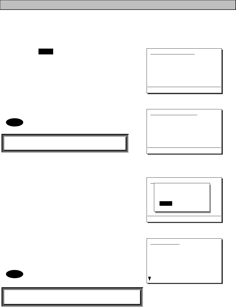
Maintenance & Inspection
6-9
6.3.2 Viewing the alarm history
The following describes how to view alarm information detected by the equipment or a history of
past occurring alarms in the 6.2 Alarm information menu.
■ Procedure ■
1
1
1.
.
.
Press the MENU key, and through
hierarchical menus, select 6.2 Alarm
information.
One of the screens shown at right is
displayed indicating if an alarm is
occurring.
The displayed alarm information is
formatted as follows.
[Unit Name] : [Alarm Number], [Information]
2
2
2.
.
.
To check the alarm history, press ENT.
The popup screen at right is displayed,
select OK.
3
3
3.
.
.
The alarm history is displayed.
Up to 100 of the latest histories are stored.
If necessary, scroll with the jog dial.
The displayed alarm history is
formatted as follows.
[Number] [Alarm & recovery time] [A: Alarm/V: Recovery]
[Unit name] : [Alarm number], [Information]
6.2)Alarm information
No data
Press ENT to view alarm history.
(If there is an alarm)
Note
Note
(If there is no alarm)
6.2)Alarm information
No data
Press ENT to view alarm history.
View alarm history?
[ OK ] [Cancel]
Alarm history
1.2008-12-31 23:59 A
PA :001,Overcurrent(A)
2.2008-12-31 23:59 A
PA :008,High-temp
3.2008-11-30 22:45 V
ATU :019,High-temp
4.2008-11-28 22:11 V
ATU :018,High voltage
6.2)Alarm information
PA :001,Overcurrent(A)
PA :008,High-temp
Press ENT to view alarm history.

Maintenance & Inspection
6-10
6.4 Software version
■ Procedure ■
To view the version of the software currently
running on the equipment, press the MENU
key, and display 6.3 Software version in the
menu list.
¾ Each software version of the transceiver,
the controller and the data terminal is
displayed as shown at right.
¾ Besides above, the software version of the
data terminal is displayed through the Help
menu.
6.3)Software version
- Controller :05.00
- WKR MODEM :03.00
- TRX :01.00
- PA :01.00
- ATU :01.00
- DTE :01.00
0.Back
Maintenance & Inspection
6-11
6.5 Troubleshooting
WARNING
This equipment is used for both distress communication and routine
communication.
Contact JRC or our agent if any problem is observed in this unit during routine
operation or inspection.
Do not open the equipment to inspect or repair internal circuits. Inspection
or repairs by anyone other than a specialized technician may result in fire,
electrical shock, or malfunction.
If internal inspection or repair is necessary, contact our service center or
agents.
6.5.1 Procedures for locating malfunctions
1) First, check the power supply voltage and connectors.
2) If there are no problems with the above, use a tester to check for errors.
The following table shows the instruments required for performing repairs and the severity of
malfunctions. If the user is to locate the malfunction himself, perform only No. 1 and No. 2.
No. Type of Malfunction Examples
1
Faults requiring no instrument to locate
・ Faulty connector contacts
・ Broken antenna cables
・ Defective switches, controls, etc.
・ Other problems that can be visually detected
2 Malfunctions that can be discovered
and repaired with a tester
・ Confirmation of power supply voltage
・ Breaks in external wiring
3
Malfunctions requiring special instrument
・ Fan malfunction in transceiver and ATU
enclosure fan
・ Crystal oscillator frequency deviation
・ Decrease in transmitting power and reception
sensitivity
・ Decrease in transmitter modulation level
・ Malfunction in semiconductors, ICs, and similar
devices

Maintenance & Inspection
6-12
6.5.2 Guide to locating faults
Use the following table as a guide to locating the causes of malfunctions in the equipment. Also,
when contacting JRC or our agency, please notify us of the malfunction conditions.
No. Symptom Typical causes
1
Nothing is displayed on the
controller or the data terminal
screen.
x Malfunction in the controller or data terminal cable
x Abnormal power supply voltage
x Malfunction in the power switch, display circuit or control
circuit
2
TX and ON is displayed but no
voice is transmitted in the TEL
mode.
x Malfunction in the handset
x Malfunction in the controller cable
x Malfunction in the AF signal transmission circuit
3 TX is displayed but ON is not,
and transmission is not possible. x Malfunction in the transmission circuit
4 TX and ON are displayed, and
transmission is not possible.
x Malfunction in the handset PTT switch (TEL mode)
x Malfunction in the electrical key connection (CW mode)
x Malfunction in the transmission circuit
5 Reception sensitivity is poor.
x Antenna damage
x Break or short circuit of antenna cable
x Malfunction in the antenna connectors
x Malfunction in the receiver circuit
6 Little or no sound from the
speaker, both static and voices.
x Malfunction in the speaker
x Malfunction in the receiver circuit
7
Radio static (noise) is output
from the speaker, but cannot
receive transmissions from other
stations.
x Antenna damage
x Break or short circuit of antenna cable
x Malfunction in the antenna connectors
x Malfunction in the receiver
The following are not faults.
Symptom Possible Causes Handling
Both Tx & Rx functions are invalid,
and the SIG meter indicates
off-the-scale.
The external BK line is ON. Stop operating the external
equipment.
The VOL control, the dimmer, and
PWR key on the controller are valid
but functions such as the RF GAIN
control are invalid.
Multiple controllers are connected,
and another controller has access
rights.
Press ENT to obtain access
rights, and after that, retry
the operation.
No response from other station via
radiotelephone or DSC call.
No operator in that station, or
unavailable to respond due to other
duties.
Wait and retry later.
When multiple controllers are
connected, access rights cannot be
obtained by pressing ENT on a
monitor controller.
Another controller with higher
priority is in use for communicating
or is performing menu operations.
After operations on the other
controller are finished,
obtain access rights.
If the system is left on a screen
other than the status display for a
while, the screen returns to the
status display.
The inactivity timer is activated and
the menu is closed.
Set the timer with the 7.3.6
Menu shutdown.
The received distress call log has
been erased without operation.
Automatically deleted the received
distress calls of 48 hours old after
that reception. (IMO A.806(19))
Or the equipment had been turned
off by such as the breaker on the
power supply.
Print and save received
messages if necessary.
When turning on the data terminal,
the start screen is displayed. But
after that, nothing is displayed.
The dimmer level is adjusted to 0
with such as Ctrl+È operation.
Adjust the dimmer level with
the DIM key on the panel of
the data terminal or Ctrl+Ç
operation.
Note
Maintenance & Inspection
6-13
6.5.3 Consumables
The following shows consumables. Please contact JRC or our agency to order parts.
Location Description Model (Part number) Replacement Guide
NKG-91 PRINTER Printer paper 7ZPJD0384
Indicating red mark on the
paper edge
DPU-414 PRINTER Printer paper 6ZCAF00252A
NKG-800 PRINTER
Printer paper 5ZPCM00020
Ink ribbon (SP-16051)
5ZZCM00003 When print becomes light
6.5.4 Repair units/parts
The repair units and replacement part units are as follows.
z NTD-2250/ 2500 TRANSCEIVER
Description Model (Part number) Notes
PA CONTROL UNIT CMC-2425/ 2450
PA UNIT CAH-2425/ 2450
LPF UNIT CFJ-2425/ 2450
EXTERNAL UNIT CQD-2419 Common for 250W and 500W
TRX UNIT CMN-2250 Common for 250W and 500W
WKR MODEM UNIT CMJ-2250 Common for 250W and 500W
z NBD-2250/ 2500 POWER SUPPLY
Description Model (Part number) Notes
DC_DC UNIT CBG-2415 Common for 250W and 500W
PA_PS UNIT CBG-2416 Common for 250W and 500W
Note) 2pcs for 500W
FILTER UNIT CBL-2415 Common for 250W and 500W
Air filter MTZ304438A Everlight scott filter
z NCM-2150 MF/HF CONTROLLER
Description Model (Part number) Notes
CONTROL UNIT CDJ-3775
AF CONT UNIT CMV-3775
LCD UNIT CDE-3770
MAIN PANEL UNIT CCK-3775
SUB PANEL UNIT CCK-3776
SPEAKER 7USJD0007
CONTROLLER CABLE 7ZCJD0343 Control cable (5 m)
Maintenance & Inspection
6-14
z NFC-2250/ 2500 ANTENNA TUNER
Description Model (Part number) Notes
MATCHING UNIT CFG-2250 For 250W only
MATCHING A UNIT CFG-2500 For 500W only
MATCHING B UNIT CFG-2503 For 500W only
ANT SW UNIT CSD-2250/ 2500
TUNER CONT CDJ-2525 Common for 250W and 500W
z NDZ-227 DATA TERMINAL
Description Model (Part number) Notes
PROCESS CIRCUIT CDC-1346B
INTERFACE UNIT CMH-3227
COLOR LCD UNIT CCN-3227 10.4 inch
LCD I/F UNIT CQC-1262
USB I/F UNIT CQD-3227
z NBB-714 BATTERY CHARGER
Description Model (Part number) Notes
AC fuse 7ZFJD0002 10A
NBB714_Dustfilter NBB714-FIL
NBB714_Fan NBB714-FAN
z NBB-724 BATTERY CHARGER
Description Model (Part number) Notes
NBB724_Dustfilter NBB724-FIL
NBB724_Fan NBB724-FAN
6.5.5 Regular replacement parts
The following shows parts that need to be replaced regularly. Please contact JRC or our agency
to order parts.
Description Model (Part number) Replacement Period
Cooling fan for PA and PS 7BZJD0006 Approx. 50,000 hours of use at
room temperature
Cooling fan for ATU 7BZJD0008 Approx. 50,000 hours of use at
room temperature
LCD unit for controller CDE-3770
Approx. 20,000 hours of continued
use at maximum brightness
LCD unit for data terminal CCN-3227
Approx. 50,000 hours of continued
use at maximum brightness

After-Sales Service
7-1
7. AFTER-SALES SERVICE
★ Warranty
The warranty period is determined by JRC's warranty regulations, but is normally
1 year from the date of purchase. Additionally, the warranty except for the body text is
submitted to contractual agreements.
★ Repair Part Inventory Period
Parts necessary for proper functioning of this equipment will be kept available for 10
years after product discontinuation.
★ When Requesting Repairs
If what appears to be a defect is detected, refer to "6.5 Troubleshooting" to check if
the equipment is actually defective.
If the problem is due to a defect, immediately stop use of the system and contact the
store where you purchased the system, or one of our branches.
z During the warranty period , if a malfunction occurs with the equipment while
in standard usage in accordance with this instruction manual, we or our
agencies will repair the malfunction at no charge at the store where the
equipment was purchased or another location specified by JRC. If the
malfunction occurs due to improper usage, fault (including the use of the virus-
infected USB flash memory), or any external abnormal condition such as fire,
pollution, abnormal voltage, natural disaster (ex. thunder storms, earthquake)
etc., JRC will repair the equipment for a fee. Furthermore, regardless of the
warranty period, orders of consumables will be charged.
z After the warranty expires , we will repair the malfunction for a fee, if repair is
possible.
z Please inform us of the following :
☆ Product name, model name, manufactured date, serial number
☆ As much information as you can provide about the malfunction (alarm
number, whether transmission is possible or not, etc.)
☆ Your company or organization name, address, and phone number
★ Periodical Maintenance Recommendation
Depending on the usage conditions, with extended use, the performance of this
equipment may degrade over time, and externally installed parts such as the antenna
may degrade due to vibration, so we recommend periodical maintenance in addition
to the standard maintenance.
Please contact the store where you purchased the equipment, or one of our
branches, to request periodical maintenance.
Periodical maintenance requires a service charge.
If you have any questions regarding after-sales service, please contact the store where
you purchased the equipment, or one of our branches.
Refer to the inside of the back cover for contact numbers and locations.
Disposal
8-1
8. DISPOSAL
Observe all rules and regulations of the local authorities when disposing of this
equipment.
Specifications
9-1
9. SPECIFICATIONS
9.1 JSS-2250/2500 MF/HF Radio Equipment
z General Specifications
Transmission frequency 1605.0 - 27500.0 kHz (100 Hz steps)
Reception frequency 90.0 - 29999.9 kHz (100 Hz steps)
Frequency stability Within ±10 Hz
Type of emission TEL mode : J3E
DSC/TLX mode : F1B
CW mode : A1A
AM mode : H3E
H2B mode : H2B
DATA mode : J2D
Channels User channels (TEL/DSC/CW) : Max. 400 ch (20 ch x 20 grp)
User channels (TLX) : Max. 400 ch (20 ch x 20 sta)
ITU preset channels : 1722 ch
Scan channels Max. 20 channels (group specification method)
Nominal frequency J3E/ A1A/ H3E/ H2B/ J2D : Carrier frequencies
F1B : Assigned frequency
Communication method in TEL Push-to-talk (simplex, semi-duplex)
Antenna impedance 50 unbalanced
Channel switching duration 15 sec or less
Interface IEC61162-1 (GPS/AME/RMS)
Compass safety distance 2.0 m
Main controls DSC call (sending and receiving), communication freq/
channel settings, Tx power settings, RF gain adjustment,
volume adjustment, LCD adjustment
Performance criteria IMO A.806(19), A.694(17), MSC68(68), MSC/Circ.862
IEC 60945 Ed.4 2002-08
Power supply voltage 90 VAC to 132 VAC, 180 VAC to 264 VAC
24 VDC (21.6 VDC to 31.2 VDC)
Current consumption
(JSS-2250/ 2500)
Transmission AC : 2kVA / 3kVA
24VDC : 40A / 40A
Reception AC : 0.5kVA / 0.5kVA
24VDC : 6A / 6A
Operating temperature range -30 to +55oC (-15 to +55 oC during normal operation)
Storage temperature range -30 to +55°C (parts exposed to condensation -30 to +70°C)
Humidity resistance No abnormality after standing 10 hours in +40°C, 93%RH
Vibration resistance (3 axes) 2 Hz - 5 Hz to 13.2 Hz : Full amplitude ±1 mm±10%
13.2 Hz to 100 Hz : Max acceleration 7 m/s2 fixed
No abnormality after testing resonance points or at 30 Hz for 2 hours
Continuous operation (TEL) No abnormality after operating continuously for 8 hours
Continuous operation (DSC,WKR) No abnormality after operating continuously for 24 hours
Category type of
the weather resistance
Antenna tuner and the junction box : Exposed
Other units : Protected
Protection rating IP22 equivalent (controller panel)
Dimensions and mass (approx)
(JSS-2250/ 2500)
Main unit (Incase of the NCU-515A Rack)
520mm(W) x 665mm(H) x 450mm(D) [ex. projections], 90kg/96kg
Antenna tuner
395mm(W) x 622mm(H) x 198mm(D) [ex. projections], 10kg/10kg
MF/HF controller
230mm(W) x 142mm(H) x 89mm(D) [ex. projections], 1.3kg
Data terminal
336mm(W) x 244mm(H) x 88mm(D) [ex. projections], 4.6kg
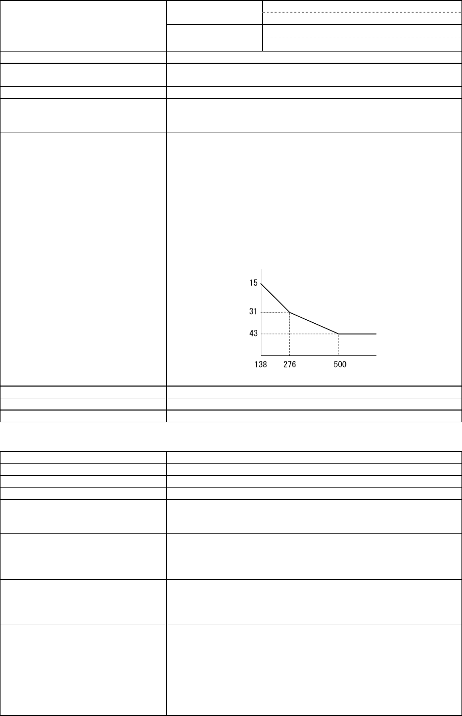
Specifications
9-2
z Transmitter
Antenna output power
(JSS-2250/ 2500)
1605.0
- 3999.9 kHz
AC : 200Wpep / 400Wpep
24VDC : 100Wpep / 100Wpep
4000.0
- 27500.0 kHz
AC : 250Wpep / 500Wpep
24VDC : 150Wpep / 150Wpep
Modulation method Low-power stage balanced modulation
Occupied bandwidth J3E/ J2D/ H2B : Within 3 kHz
F1B/ A1A : Within 0.5 kHz
Carrier suppression (J3E) 40 dB or more
Unwanted emissions in the
out-of-band domain
(JSS-2250/ 2500)
Mean power of 50 mW or lower, or 67/70 dB or more lower
than the mean power of the basic frequency
Unwanted emissions in the
spurious domain
JSS-2250/2500
At J3E:
1.5 to 4.5 kHz : 28/28 dB or more
4.5 to 7.5 kHz : 35/35 dB or more
7.5 kHz and upwards : 64/67 dB or more
At F1B:
0.25 to 0.5 kHz : 28/28 dB or more
0.50 to 1.25 kHz : 35/35 dB or more
1.25 kHz and upwards : 67/70 dB or more
And following
Mistuned frequency [Hz]
A
ttenuation [dB]
Overall distortion and noise -20 dB or less
AF frequency response Deviation is within 6 dB in 350 Hz to 2700 Hz range.
Tone frequency 1500 Hz or 1400 Hz
z Receiver
Receiving system Double superheterodyne
1st IF 70.036 MHz
2nd IF 36 kHz
Reception frequency stability Within ±10 Hz
Sensitivity (SINAD 20dB) J3E : 2.5 uV or less (1605.0 to 27500.0 kHz)
F1B : 0.7 uV or less (1605.0 to 27500.0 kHz)
A1A : 1.4 uV or less (1605.0 to 27500.0 kHz)
Pass band/Adjacent signal
selectivity
J3E : 2.4 - 3.0 kHz (6 dB bandwidth) within
±2.1 kHz (66 dB bandwidth)
F1B : 270 - 300Hz (6 dB bandwidth) within
±550 Hz (60 dB bandwidth)
Spurious response J3E : 60 dB or more
F1B : Symbol error rate of 1% or better at a wanted
signal level of 10 uV and an unwanted signal
level of 31.6 mV separated by 750 Hz
Blocking/Desensitization J3E : When an unwanted signal level separated by 3
kHz is added to the wanted signal level of 10
uV, the unwanted signal input voltage
suppressing output of the wanted signal by 3
dB is 10 mV or more.
F1B : Symbol error rate of 1% or better at a wanted
signal level of 10 uV and an unwanted signal
level of 1 mV separated by 500 Hz

Specifications
9-3
Overall distortion and noise When an input signal level of 30 uV is applied, the ratio
between low-frequency output 1000 Hz and unwanted
components contained in that output is 30 dB or more.
Conducted spurious emission Power emitted from antenna terminal is 2 nW or less (9kHz
- 2GHz) and 20 nW or less (2GHz - 4GHz).
Clarifier variable range ±200 Hz (1 Hz steps)
Antenna impedance 50 unbalanced
Line output 0 dBm 600 (balanced)
z DSC Watch Keeping Receiver
Reception frequency Distress and safety frequencies of 2187.5 kHz and 8414.5
kHz, and additionally on one or more of the 4207.5 kHz/
6312.0 kHz/ 12577.0 kHz/ 16804.5 kHz
Receiving system Double superheterodyne
1st IF 40.04025 MHz
2nd IF 40.25 kHz
Frequency stability Within ±10 Hz
Sensitivity 1% or lower symbol error rate at reception input voltage of
1µV
Passband 6 dB bandwidth : 270 - 300 Hz
30 dB bandwidth : Within ±380 Hz
60 dB bandwidth : Within ±550 Hz
Spurious response Symbol error rate of 1% or better when an unwanted signal
level of 31.6 mV is applied to a wanted signal level of 10
uv from an intermediate frequency separated by 750 Hz or
more through to a frequency 3x the test frequency
Blocking/Desensitization Symbol error rate of 1% or better at a wanted signal level
of 10 uV and an unwanted signal level of 1 mV separated
by 500 Hz
Conducted spurious emission Power emitted from antenna terminal is 2 nW or less.
Antenna impedance 50 unbalanced
z DSC Modem
Modulation rate Within 100 baud ±30x10-6
Modulation method FSK (sub-carrier: 1700 Hz)
Mark frequency (Y) Transmission : Within 1615 Hz ±0.5 Hz
Reception (permissible value) : Within 1615 Hz ±20 Hz
Space frequency (B) Transmission : Within 1785 Hz ±0.5 Hz
Reception (permissible value) : Within 1785 Hz ±20 Hz
DSC Protocol ITU-R recommendation M.493-13 (Class A and B)
DSC operation standards ITU-R recommendation M.541-9, M.821-1
DSC code 10-bit error detecting code
Message storage 20 Rx distress, 20 Rx others, 20 Tx messages
z NBDP Modem
Modulation rate Within 100baud ±30x10-6 以内
Modulation method FSK (sub-carrier:1700Hz)
Mark frequency (Y) Transmission : Within 1615 Hz ±0.5 Hz
Reception (permissible value) : Within 1615 Hz ±20 Hz
Space frequency (B) Transmission : Within 1785 Hz ±0.5 Hz
Reception (permissible value) : Within 1785 Hz ±20 Hz
NBDP Protocol ITU-R recommendation M.476-5,M.491-1,M.492-6,M.625-4
ITU-T recommendation F.1, F.130, S.6
NBDP code 7-bit error detecting code

Specifications
9-4
z Antenna tuner
Frequency range 1605.0 - 27500.0 kHz
Maximum input power
(JSS-2250/ 2500)
1605.0 - 3999.9 kHz 250Wpep / 500Wpep
4000.0 - 27500.0 kHz 300Wpep / 700Wpep
SWR after tuning 2:1 or less
Tuning method Preset or auto-tuning
Tuning time Preset tuning: 0.5 seconds, auto-tuning: max. 45 seconds
Power supply 24 VDC (21.6 VDC to 24.7 VDC)
z MF/HF controller
Communication speed 57.6 kbps
Communication interface RS-485 and RS-232C, and Centronics compliant
Microphone input impedance 150 balanced
Standard modulation input -54 dBm
Audio output Internal loud speaker (8) : 5W max
External speaker impedance : 8 or more
Handset phone (150) : Rated 1mW or more
LCD display 3.8 inch FSTN monochrome, 320 x 240 dot, LED backlight
z Data terminal
Communication speed 4.8kbps
Communication interface RS-232C
USB interface USB 2.0, FAT16/32 file format
Keyboard interface PS/2
Printer interface Centronics compliant
LCD display 10.4 inch TFT color, 640x480 dots, CCFL backlight
Standard brightness 450cd/m2, Viewing angle 160 ゚/140 ゚
Contrast 600:1
● Keyboard
Communication interface Serial two wire interactive transmission
Connector Mini DIN 5Pin
Durability 20,000,000 times
● Printer (NKG-800/NKG-900)
Printing system Serial impact dot matrix
Communication interface Centronics compliant
Supported fonts ANK FX850 mode 324 characters
IBM Proprinter II mode 264 characters
Paper feed system Roll paper holder
Paper type 209 - 216 mm (8.23 - 8.50") roll paper
Buffer size ANK FX850 mode 21 kbytes
IBM Proprinter II mode 9.3 kbytes
Density adjustment Manual (non-stepped)
Power supply voltage 10.2 VDC - 31.2 VDC
Power consumption Maximum 35 W

Specifications
9-5
9.2 Options
(1) Battery charger (NBB-714)
Source voltage 90 VAC to 132 VAC or 180 VAC to 264 VAC (50/60 Hz)
Current consumption Charging : 8 A or less (100 VAC input)
4 A or less (220 VAC input)
Discharging : 0.3 A or less (at 24 VDC ope)
Charging current Maximum 10 A
Charging circuit/ characteristic Floating charge
16 VDC or more: Constant voltage or current characteristic
Less than 16 VDC: Reduced current characteristic*
(*) Foldback current limiting characteristic
Functions Overvoltage input protection, Reverse polarity protection,
Dimmer lamp, Alarm mute with remote control
Alarm type Batt low/high voltage, Internal temperature, AC fail,
Other abnormal charging
Temperature range for full performance
-15°C - +55°C
Operating temperature range -15°C - +55°C
Storage temperature range -25°C - +65°C
Humidity resistance No abnormality after standing 10 hours in +40°C, 93% RH
Vibration resistance (3 axes) 2 Hz - 5 Hz to 13.2 Hz: : Full amplitude ±1 mm±10%
13.2 Hz to 100 Hz: : Maximum acceleration 7
m/s2 fixed
No abnormality after testing resonance points or at 30 Hz
for more than 2 hours
(2) Battery charger (NBB-724)
Source voltage 90 VAC to 132 VAC or 180 VAC to 264 VAC (50/60 Hz)
Current consumption Charging : 15 A or less (100 VAC input)
8 A or less (220 VAC input)
Discharging : 0.5 A or less (at 24 VDC ope)
Charging current Maximum 22 A (Common to Floating & Equalizing charge)
Charging circuit/ characteristic Floating charge and equalizing charge
18 VDC or more: Constant voltage or current characteristic
Less than 18 VDC: Reduced current characteristic*
(*) Foldback current limiting characteristic
Functions Overvoltage input protection, Reverse polarity protection,
Dimmer lamp, Float/Equal changing, DC ope, Batt temp
Alarm type Batt low/high voltage, Internal temperature,
Other abnormal charging
Temperature range for full performance
-15°C - +55°C
Operating temperature range -15°C - +55°C
Storage temperature range -25°C - +65°C
Humidity resistance No abnormality after standing 10 hours in +40°C, 93% RH
Vibration resistance (3 axes) 2 Hz - 5 Hz to 13.2 Hz: : Full amplitude ±1 mm±10%
13.2 Hz to 100 Hz: : Maximum acceleration 7
m/s2 fixed
No abnormality after testing resonance points or at 30 Hz
for more than 2 hours

Specifications
9-6
(3) Printer (NKG-91)
Printing system Thermal line dot
Communication interface RS-232C, 4.8/9.6/38.4 kbps
Data control RTS/CTS
Data buffer 4096 byte
Maximum print speed 20 mm/sec or more
Roll paper width 58 mm
Power supply voltage 6.5 VDC (5 VDC to 8.7 VDC)
Current consumption Maximum 2 A
(4) Printer (DPU-414)
Printing system Thermal serial dot
Communication interface RS-232C, 4.8k/9.6k/38.4 kbps
Data control HW busy
Data buffer About 28 Kbyte
Maximum print speed 52.5 cps
Roll paper width 112 mm
Power voltage 6.5 VDC
Current consumption Maximum 2 A
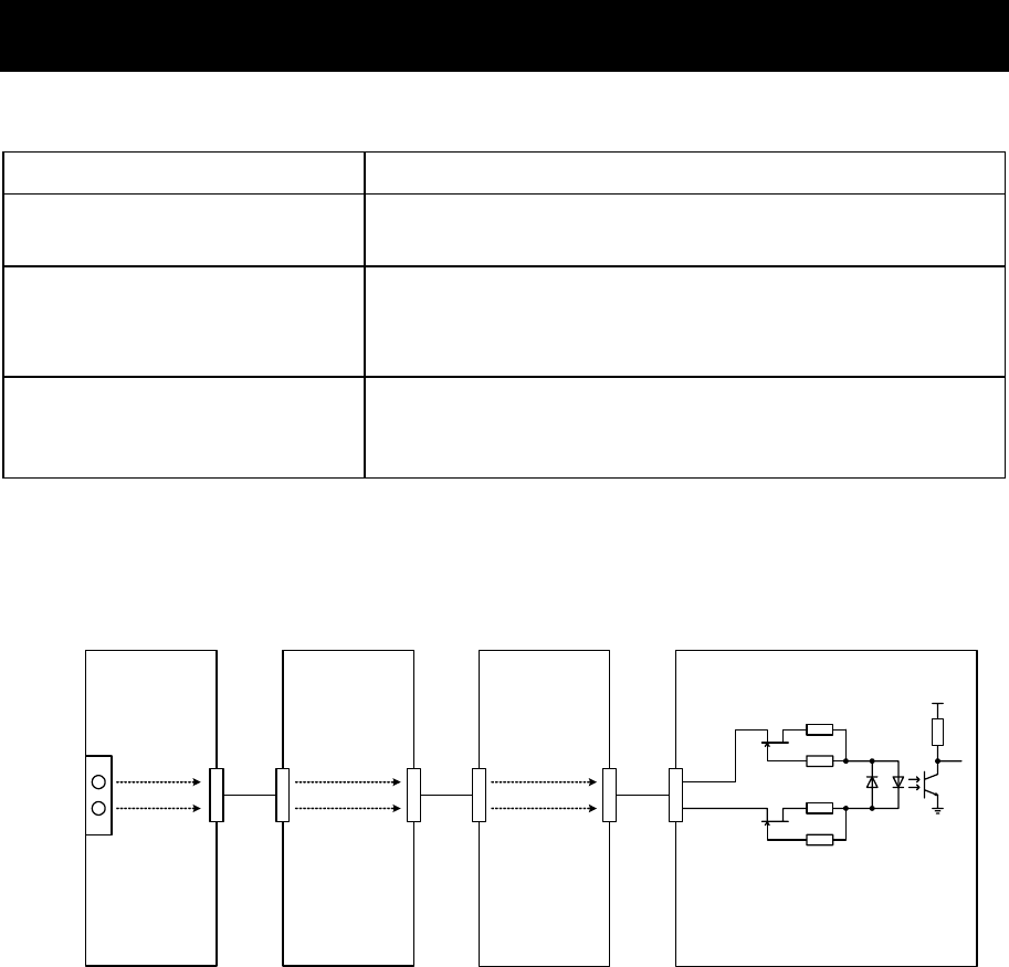
Specifications
9-7
9.3 Peripheral interfaces
(1) GPS or other navigation aid interface
Interface standard NMEA0183/ IEC61162-1 Ed.4 (2010-11) compliant
Protocol 4800 bps, start 1 bit, data 8 bit, stop 1 bit
Non parity
Input sentence
NMEA0183 V1.5: GGA/ GLL/ RMC
V2.0: GGA/ GLL/ RMC/ ZDA
V2.3: GGA/ GLL/ RMC/ GNS/ ZDA
(Talker = "GP" or other)
Data type
Ship position & time information: GGA/ GNS/ GLL/ RMC
Date information: ZDA/ RMC
Equipment time information: ZDA/ GGA/ GNS/ GLL/ RMC
(1.1) Electrical description
■ Load requirements
Current consumption :2mA at 2V or less
Maximum input voltage :±15V or more
Recommended operating current :2mA or more
CMC-2425/2450
PA CONTROL
UNIT
CQD-2417
TERMINAL
BOARD
TB204
26
27
GPS_RX-A
GPS_RX-B
J202
W30
J102 J172
CMN-2250
TRX UNIT
J1111 J1131
W13
CMJ-2250
WKR MODEM UNIT
J502
W14 1
2
+3.3V
PHT501
CD503
R541
R542
R543
R544
TR501
TR502
R541, R543: 270
R542, R544: 10k
R540
3.3k

Specifications
9-8
(1.2) List of sentences and associated data fields
(1.2.1) GGA – Global positioning system (GPS) fix data
$--GGA, hhmmss, llll.ll, a, yyyyy.yy, a, x, xx, x.x, x.x, M, x.x, M, x.x, xxxx *hh<CR><LF>
Differential reference
station ID, 0000-1023
Age of differential GPS data
Units of geoidal separation, m
Geoidal separation
Units of antenna altitude, m
Antenna altitude above/below mean sea level
(geoid)
Horizontal dilution of precision
Number of satellites in use, 00-12, may be different
from the number in view
GPS quality indicator
Longitude E/W
Latitude N/S
UTC of position
(1.2.2) GLL – Geographic position – Latitude/longitude
$--GLL, llll.ll, a, yyyyy.yy, a, hhmmss.ss, A, a *hh<CR><LF>
Mode indicator:
A = Autonomous, D = Differential, E = Estimated
M = Manual input, S = Simulator, N = Data not valid
Status: A= data valid, V= data invalid
UTC of position
Longitude, E/W
Latitude, N/S

Specifications
9-9
(1.2.3) RMC – Recommended minimum specific GNSS data
$--RMC, hhmmss.ss, A, llll.ll, a, yyyyy.yy, a, x.x, x.x, xxxxxx, x.x, a, a, a *hh<CR><LF>
Navigational status
Mode indicator:
A = Autonomous, D = Differential,
E = Estimated, F = Float RTK,
M = Manual input, N = Data not valid
P = Precise, R = Real Time Kinematic
S = Simulator,
Magnetic variation, degrees, E/W
Date: dd/mm/yy
Course over ground, degrees true
Speed over ground, knots
Longitude, E/W
Latitude, N/S
Status: A = data valid, V = navigation receiver warning
UTC of position fix
(1.2.4) GNS – GNSS fix data
$--GNS, hhmmss.ss, llll.ll, a, yyyyy.yy, a, c---c, xx, x.x, x.x, x.x, x.x, x.x, a *hh<CR><LF>
Navigational status
Differential reference
station ID
Age of differential data
Geoidal separation, m
Antenna altitude, m, re: mean-sea-level
(geoid)
HDOP
Total number of satellites in use, 00-99
Mode indicator:
N = No fix, A = Autonomous, D = Differential,
P = Precise, R = Real Time Kinematic, F = Float RTK,
E = Estimated, M = Manual input, S = Simulator
Longitude, E/W
Latitude, N/S
UTC of position

Specifications
9-10
(1.2.5) ZDA – Time and date
$--ZDA, hhmmss.ss, xx, xx, xxxx, xx, xx *hh<CR><LF>
Local zone minutes, 00 to +59
Local zone hours, 00 h to ±13 h
Year (UTC)
Month, 01 to 12 (UTC)
Day, 01 to 31 (UTC)
UTC
(2) RMS interface
Interface standard IEC61162-1 compliant
Protocol 4800 bps, start 1 bit, data 8 bit, stop 1 bit
Non parity
Output message
IEC61162-1 compliant proprietary sentence
$PJRCL sentence (for RMS log saving)
$PJRCM sentence
(Device ID = "CT")
Data type Model number, serial number, self-diagnosis information,
etc.
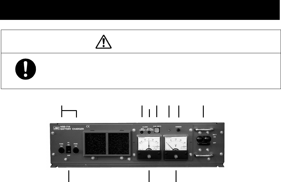
Options Operation
10-1
10. OPTIONS OPERATION
10.1 Battery charger (NBB-714)
CAUTION
When replacing fuses, always use fuses of the same type.
1. 10A fuse ························ AC mains fuses (2pcs)
2. AC switch ······················ Turns on the AC mains power supply.
3. BATT LOW/HIGH lamp ···· This lamp turns on and the buzzer sounds to indicate low
voltage of the battery (approx. 21.5V). And also turns on and
the buzzer sounds to indicate overvoltage of the battery
(approx. 32.2 ~ 37.0V) and then, turns off the BATT breaker.
4. AC FAIL/ CHG ALARM ···· This lamp turns on and the buzzer sounds to indicate any one
of the following alarms.
・ While the BATT breaker is ON, the AC switch is OFF or any
AC fails such as the power failure or the blowout of fuses.
・ While the AC switch is ON, the BATT breaker is OFF.
・ Over discharge detection (16V or less)
Note) If AC input is ON, charging is available without
tripping the breaker.
・ Overheat detection (+80C)
5. Current meter ················ Indicates the charge current (+) or discharge current (-).
6. ALM MUTE switch ·········· Silences the active alarm buzzer sound.
7. Alarm buzzer
8. Voltage meter ················ Indicates the output voltage of the battery.
9. Dimmer control ·············· Adjusts the dimmer level of alarm lamps.
Note) Unable to turn off completely.
10. BATT breaker ················· When turned on, connects the internal circuit to the battery,
and after that turning on the AC breaker enables charging of
the battery. Note that if detected over discharge of the
battery (approx. 19.5V), this breaker trips automatically.
346 7 910
1
58
2

Options Operation
10-2
■ Procedure ■
Turn on the AC switch and the BATT breaker to start charging the battery.
¾ The AC FAIL/CHG ALARM is activated if the AC switch and BATT breaker are turned ON
at different timing. However it is due to the notification function of the switch/breaker
ON/OFF state and is NOT the alarm for any malfunction.
¾ The NBB-714 is a battery charger for the maintenance free battery only, i.e. the
charging type is floating only and not providing the equalizing charge.
■ Replacing fuses ■
To replace fuses, turn off the AC switch and the BATT breaker first, and then unscrew the
both two fuse cases as shown below to replace them.
Note) The appearance of the blowout fuses look like normal. So when checking if the
fuses are blown or not, always use the tester.
・ The battery can be used as a secondary power source when the BATT breaker is
ON while the AC breaker is OFF. However in this case, be sure not to cause over
discharge condition.
・ When any alarm is occurred, treat it as follows.
- BATT HIGH ······················ When the battery overvoltage (32.2~37.0V) is
detected, trips the BATT breaker. In this case,
turn off the AC switch. And then, after the
voltage is recovered to normal, turn on the AC
switch and the BATT breaker.
Note) In this case, the charge alarm is also
detected due to the BATT breaker trip and the
CHG ALARM is activated.
- BATT LOW ······················· Carry on charging. This alarm is cleared
automatically after the battery voltage increases
to approx. 23.5V.
- AC FAIL/CHG ALARM ········· - Turn on the AC input/switch.
- After checking that the battery voltage is not
overvoltage, turn on the BATT breaker.
- If the battery is over discharge condition (16V),
turn on both the AC switch and the BATT breaker
to charge the battery.
- High temperature ·············· The built-in charging circuit is disconnected until
the temperature returns to the normal condition
(60℃ or lower) automatically
Note
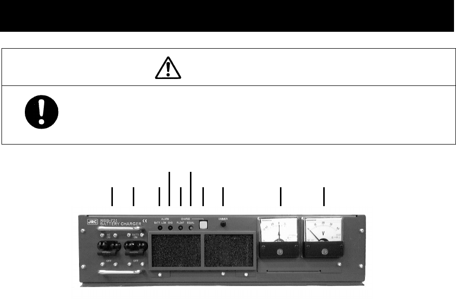
Options Operation
10-3
10.2 Battery charger (NBB-724)
CAUTION
The batteries, except for sealed lead-acid batteries that require no
equalization, should be carried out the equalizing charge at least every six
months
3 5
4 6
7 8 910
1. AC breaker ·················· When turned on, enables to use the AC mains input.
2. BATT breaker ··············· When turned on, connects the internal circuit to the battery,
and after that turning on the AC breaker enables charging of
the battery. Note that if detected over discharge of the
battery (approx. 19.5V), this breaker trips automatically.
3. BATT LOW alarm lamp ··· This lamp turns on and the buzzer sounds to indicate low
voltage of the battery (approx. 21.5V).
4. CHG alarm lamp ·········· This lamp turns on (or blinks*) and the buzzer sounds to
indicate any one of the following alarms.
・The BATT breaker is OFF while the AC breaker is ON.
・Over voltage (equalizing charge voltage + 1.0V)
・High temperature of the charging circuit (+75℃) *
5. FLOAT charge lamp ······ This lamp turns on during the floating charge operation.
6. EQUAL charge lamp ····· This lamp turns on during the equalizing charge operation.
7.
CHARGE mode switch ····
Changes the charge mode between floating and equalizing charge.
8. Dimmer control ············ Adjusts the dimmer level.
9. Current meter ·············· Indicates the charge current (+) or discharge current (-).
10. Voltage meter ·············· Indicates the output voltage of the battery.
1 2

Options Operation
10-4
(1) Charging a battery in the floating mode
■ Procedure ■
Turn on the AC and BATT breakers.
¾ FLOAT lamp turns on during the floating charge operation.
¾ When turning on the AC breaker prior to BATT breaker, CHG alarm lamp turns on and
the buzzer sounds. But this is not malfunction as mentioned above.
(2) Charging a battery in the equalizing mode
■ Procedure ■
1
1
1.
.
.
Turn on the AC and BATT breakers.
Make sure FLOAT lamp is turned on and the battery charge is started in the floating mode.
2
2
2.
.
.
Press the CHARGE mode switch.
¾ The lighting lamp is changed from FLOAT to EQUAL to indicate operating in the
equalizing mode.
¾ The charging mode can be switched between FLOAT and EQUAL alternately.
3
3
3.
.
.
When the equalizing charge is completed, returns to the floating mode automatically.
The equalizing charge is continued until the charge current goes down to approx. 3.0A or
until 10 hours elapse.
・ The battery can be used as a secondary power source when the BATT breaker is
ON while the AC breaker is OFF. However in this case, be sure not to cause over
discharge condition.
・ When any alarm is occurred, treat it as follows.
- BATT LOW ················ Carry on charging. This alarm is cleared automatically
after the battery voltage increases to approx. 23.5V.
- BATT breaker OFF ····· Turn the BATT breaker on.
- Over voltage ············· Turn off the AC and BATT breakers until the battery
voltage returns to the normal condition.
- High temperature ······· The built-in charging circuit is disconnected until the
temperature returns to the normal condition (60℃ or
lower) automatically
- Over discharge ·········· When the BATT breaker trips, turn on the breakers in
the order of AC and BATT so that the charge operation
is restarted.
Note
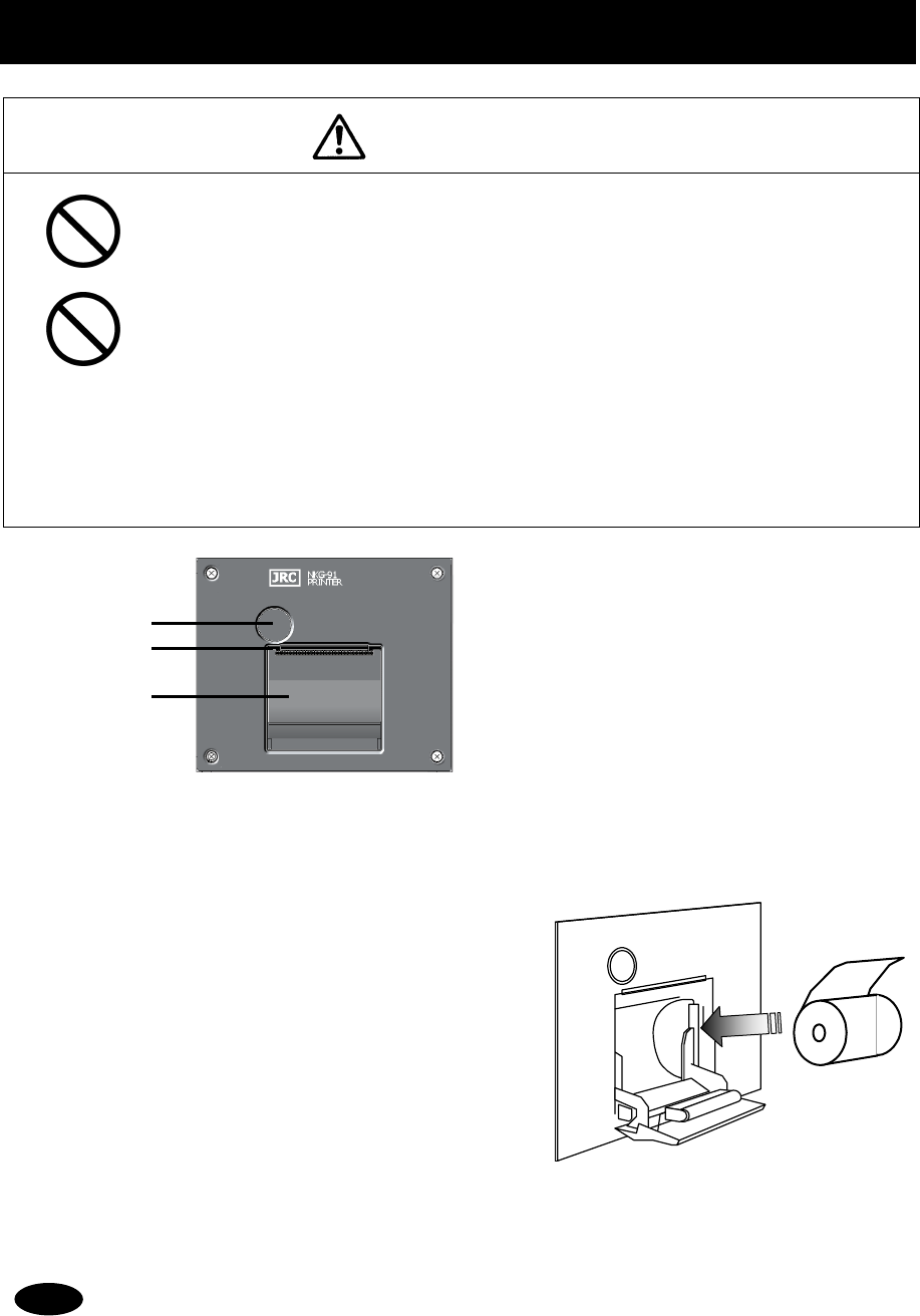
Options Operation
10-5
10.3 Printer (NKG-91)
CAUTION
The thermal head of the NKG-91 printer may be very hot after printing. Do
not touch the thermal head of the printer. Make sure that the thermal head
is cool before replacing the paper or cleaning the thermal head.
The paper used in the NKG-91 printer is heat sensitive. Take the following
precautions when using this paper.
・ Store the paper away from heat, humidity, or heat sources.
・
Do not rub the paper with any hard objects.
・
Do not place the paper near organic solvents.
・
Do not allow the paper to come in contact with polyvinyl chloride film,
erasers, or adhesive tape for long periods of time.
・
Keep the paper away from freshly copied diazo type or wet process copy
paper.
■ Loading the printer paper ■
1
1
1.
.
.
Press the paper cover open button.
The paper cover will open.
2
2
2.
.
.
Insert the paper as shown in the diagram at
right.
Position the paper such that the leading edge
extends outside the printer, and press both
sides of the paper cover to close it.
The printer will be turned on and off simultaneously with the equipment.
1
2
3
1. Paper cover open button
2. Paper cutter
3. Paper cover
Note
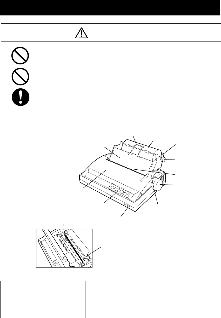
Options Operation
10-6
10.4 Printer (NKG-800)
CAUTION
The print head of the NKG-800 printer may be very hot after printing. Do
not touch the print head of the printer. Make sure that the print head is cool
before replacing the paper or cleaning the print head.
Do not use the NKG-800 printer if there is no ink ribbon cartridge or paper.
Do not twist the ink ribbon when installing the ink ribbon cartridge.
Before opening and closing the cover of the NKG-800 printer, turn off the
printer. Wait more than 2 seconds after turning the printer off before turning it
back on again so it can initialize correctly.
The following shows the functions of the operation panel.
P.PARK FF LF NLQ ONLINE
Paper Park
Rewinds the roll
paper.
Feed Form
Feeds paper one
page at a time.
Line Feed
Feeds the paper
one line at a
time.
High-quality
Printing
Switches the
printer to the
high-quality
printing mode.
Printer Ready
Setting
The printer is
ready for
printing when
the lamp is lit.
Note 1: Before performing P.PARK/FF/LF/NLQ, press ONLINE to set the printer offline (lamp out).
Note 2: When the printer runs out of roll paper, the P.OUT lamp lights and the printer
automatically goes offline.
Platen
Paper is fed in contact
with this platen when the
friction lever is pushed
towards the back.
Power switch
Operation
panel
Roll paper cover
Roll support cover
Prevents printed roll paper
from being wound back in. Roll paper Roll paper stand
Roll bar
Passes through
the printing roll
paper.
Roll paper cutter
Paper feed knob
Friction lever
When replacing the roll paper,
pull this lever towards the front
before inserting the paper, and
return it towards the back after
paper is inserted.
Printer cover
Print head
Contacts the roll
p
a
p
er for
p
rintin
g
.
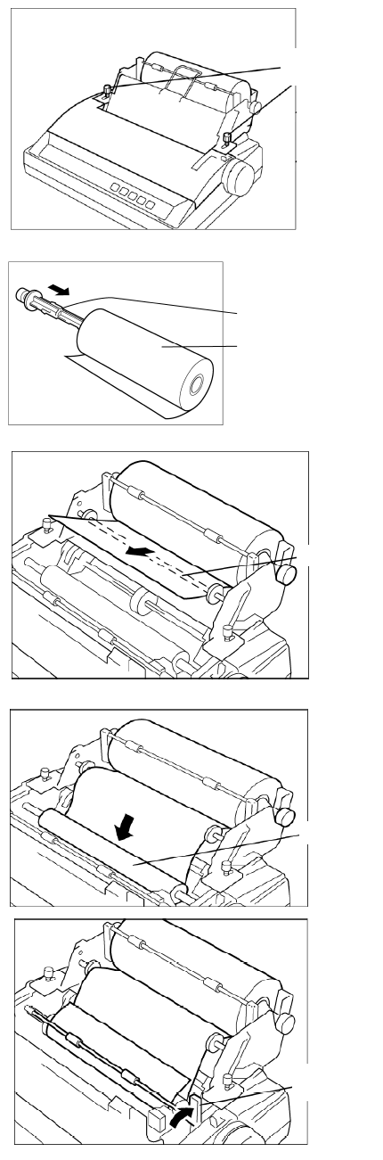
Options Operation
10-7
■ Loading the printer paper ■
1
1
1.
.
.
Turn the printer OFF, loosen the roll paper
stand fixing screws, and slide the stand
backwards to open the printer cover.
At this step, also remove the roll paper cover.
2
2
2.
.
.
Pass the roll bar through the roll paper,
and install the roll paper onto the roll paper
stand paying attention to its orientation.
3
3
3.
.
.
Pass the roll paper over the guide bar as
shown in the figure at right.
4
4
4.
.
.
Pull the friction lever towards the front, and
insert the leading edge of the paper into
the rear of the platen. Then, return the
friction lever to the back, and turn the
paper feed knob to feed the paper out.
5
5
5.
.
.
Lift the paper load lever up to hold down
paper fed out of the platen.
Fixing
screws
Roll bar
Roll paper
Guide bar
Platen
Paper
load lever
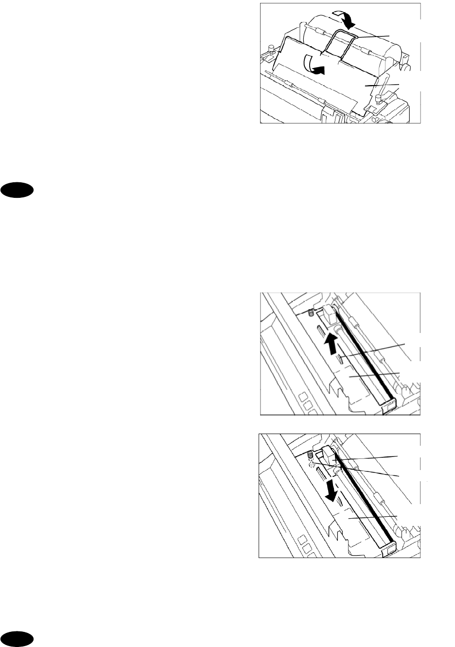
Options Operation
10-8
6
6
6.
.
.
Return the roll paper cover to its original
position, and place the roll support cover
as shown in the figure at right.
7
7
7.
.
.
Close the printer cover, return the roll
paper stand to its original position, and
tighten the fixing screws.
To perform a print test, turn the printer on with the LF key held down.
To end the print test, turn the printer off.
■ Replacing the ink ribbon ■
1
1
1.
.
.
Turn the printer on, and following the same
procedure as that in the previous section,
open the printer cover, lift up the ink ribbon
cartridge by holding the projection on the
cartridge, and lift the cartridge up to
remove it.
2
2
2.
.
.
Using the knob on the new cartridge to make
the ribbon taut, manually move the print
head to the left edge, and attach the ribbon
so that it is between the ribbon mask and
print head.
3
3
3.
.
.
Close the printer cover, return the roll paper
stand to its original position, and tighten the
fixing screws.
For other details, check the NKG-800 Installation Guide. The printer's operation
mode can be set by the DIP switches. However, leave the DIP switch settings at
their factory defaults (all off) when using the printer connected to the equipment.
Roll support
cover
Roll paper
cover
Projection
Ink ribbon
cartridge
Print head
Knob
Ink ribbon
cartridge
Note
Note
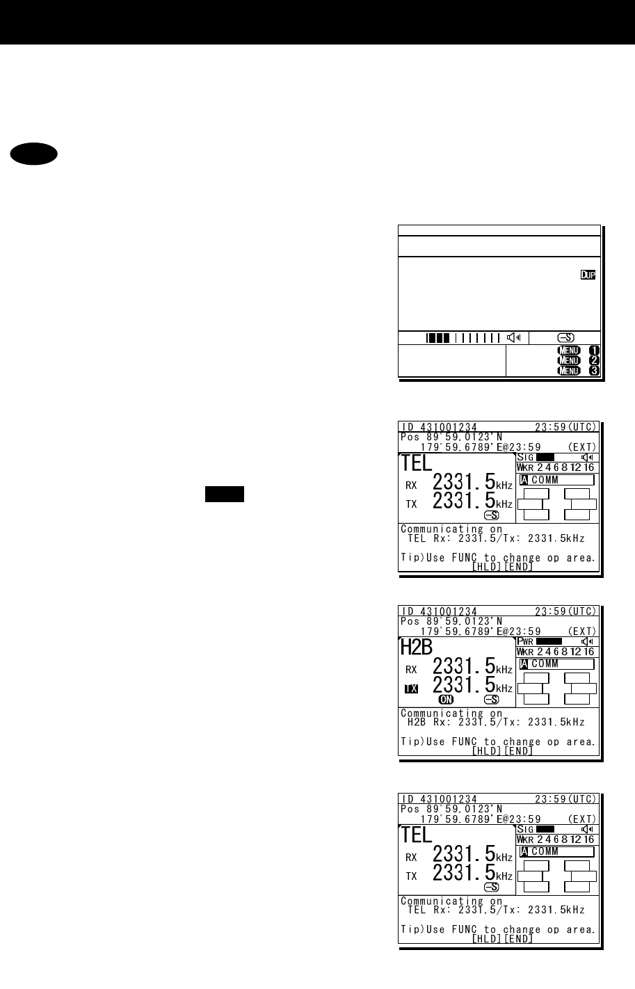
Options Operation
10-9
10.5 Operations using a SELCALL unit
The JSS-2250/2500 MF/HF radio equipment can be connected to external selective
calling devices for fishing boats (Selcall) to send signals for calling Selcall buoys or
Selcall receivers on ships.
For details on operations of the Selcall device, refer to the manuals of that device.
■ Procedure ■
1
1
1.
.
.
Finish all menu operations to return the
screen to the status display.
When a transmission is made from the
Selcall device while menus are displayed,
menus can no longer be operated until
transmission ends.
2
2
2.
.
.
Set the communication mode to TEL and
the assigned frequency (e.g. 2331.5 kHz)
for transmitting on the Selcall device in
the free frequency input mode. Then tune
the antenna by pressing key.
In this case, input both the Rx and Tx
frequencies as simplex frequencies.
3
3
3.
.
.
Operate the Selcall device to start
transmission.
When transmission is started, the
communications mode automatically
changes to H2B as shown at right.
4
4
4.
.
.
When transmission ends, the
communications mode returns to the
original mode.
Note
ANT
TUNE
TEL ITU- 401
4357.0
4065.0
RX kHz
TX kHz
NonDST: +
DROBOS: +
EdtDST: +
ID 431001234 23:59(UTC)
Pos 89゚59.0123'N
179゚59.6789'E@23:59 (EXT)
SIG
WKR scan bands:
2 4 6 8 12 16MHz
Options Operation
10-10

Appendix
11-1
11. Appendix
This section lists frequencies used for DSC such as frequencies used for routine calls
and frequencies used for safety and distress calls. It also lists the channel list of ITU
frequencies built-in to this equipment and the instructions for operating the MF/HF radio
equipment.
11.1 Frequencies for distress and safety calls
The following is a list of international1 transmission frequencies (all simplex) used by coast and
ship stations for distress and safety purposes either with DSC, radiotelephone or telex. CH No.
indicates channel numbers preprogrammed to this equipment.
(DSC)
(radiotelephone) (telex)
CH No. TRx(kHz) CH No. TRx(kHz)CH No. TRx(kHz)
--- 2187.5 --- 2182.0 --- 2174.5
401 4207.5 --- 4125.0 411 4177.5
601 6312.0 --- 6215.0 611 6268.0
801 8414.5 833 8291.0 801 8376.5
1201 12577.0 --- 12290.0 1287 12520.0
1601 16804.5 --- 16420.0 1624 16695.0
- When making DSC calls, the frequencies above can only be used if the
message category is Distress, Urgency, or Safety.
- The DSC frequencies listed above are watched by the DSC watch keeping
receiver.
- The radiotelephone frequencies other than 8291.0 kHz are the same as the
transmission frequencies of ITU channels 421, 606, 1221 and 1621. However,
when making calls for distress and safety purposes, use these frequencies2 as
simplex channels.
1 RR Appendix 15
2 RR Article 52.221.3
Note

Appendix
11-2
11.2 National DSC frequencies for routine calls
When ship and coast stations call national stations for purposes that are not safety or distress
purposes, normally use the national frequencies allocated by the administrator prior to using the
international frequencies listed later.3 The frequencies for Japan are as follows. Additionally, the
pair frequencies are used to make a call to the coast station.
Tx (kHz) Rx (kHz) Tx (kHz) Rx (kHz) Tx (kHz) Rx (kHz)
2169.0 8391.5 8431.5 18872.0 19682.5
4180.5 4218.0 12521.0 12623.0 22318.0 22410.0
6275.5 6326.5 16721.0 16844.0 25175.0 26103.0
11.3 International DSC frequencies for routine calls
The following international4 frequencies are used when calling ship and coast stations via DSC if
the other station's nationality or the frequency they are watching is not know, except for safety or
distress calls. CH No. indicates channel numbers preprogrammed to this equipment.
CH No. Tx (kHz) Rx (kHz) CH No. Tx (kHz) Rx (kHz)
--- 2189.5 2177.0
1602 16805.0 16903.0
402 4208.0 4219.5 1603 16805.5 16903.5
403 4208.5 4220.0 1604 16806.0 16904.0
404 4209.0 4220.5
1801 18898.5 19703.5
602 6312.5 6331.0 1802 18899.0 19704.0
603 6313.0 6331.5 1803 18899.5 19704.5
604 6313.5 6332.0
2201 22374.5 22444.0
802 8415.0 8436.5 2202 22375.0 22444.5
803 8415.5 8437.0 2203 22375.5 22445.0
804 8416.0 8437.5
2501 25208.5 26121.0
1202 12577.5 12657.0 2502 25209.0 26121.5
1203 12578.0 12657.5 2503 25209.5 26122.0
1204 12578.5 12658.0
- The above frequencies can only be used when the DSC message category is
Routine.
- The above table lists the sending and receiving frequencies (duplex) when a
ship station calls a coast station.
- Normally routine calls between ship stations use 2177.0 kHz (simplex) as first
choice frequency.
- Channels not listed in the table above (401/601/801/1201/1601) are the
frequencies listed earlier for distress and safety purposes.
- In the table above, channels 402/602/802/1202/1602/1801/2201/2501 should
be selected first when making routine DSC calls on international frequencies.5
3 ITU-R M.541-9 Annex 3 4.1.2
4 RR Appendix 15
5 RR Appendix 17 part A footnote l
Note

Appendix
11-3
11.4 ITU channel list (TEL/CW/TLX)
This section lists the channels preprogrammed into this equipment as TEL, CW and TLX ITU
frequencies.
(1) Radiotelephone mode (ITU-RR Appendix 17)
CH No. Tx (kHz) Rx (kHz) Remarks
401 4065.0 4357.0
402 4068.0 4360.0
403 4071.0 4363.0
404 4074.0 4366.0
405 4077.0 4369.0
406 4080.0 4372.0
407 4083.0 4375.0
408 4086.0 4378.0
409 4089.0 4381.0
410 4092.0 4384.0
411 4095.0 4387.0
412 4098.0 4390.0
413 4101.0 4393.0
414 4104.0 4396.0
415 4107.0 4399.0
416 4110.0 4402.0
417 4113.0 4405.0
418 4116.0 4408.0
419 4119.0 4411.0
420 4122.0 4414.0
421 4125.0 4417.0 (*1)(*2)
422 4128.0 4420.0
423 4131.0 4423.0
424 4134.0 4426.0
425 4137.0 4429.0
426 4140.0 4432.0
427 4143.0 4435.0
428 4146.0 4146.0 Simplex(*4)
429 4149.0 4149.0 Simplex(*5)
601 6200.0 6501.0
602 6203.0 6504.0
603 6206.0 6507.0
604 6209.0 6510.0
605 6212.0 6513.0
606 6215.0 6516.0 (*1)(*2)
CH No. Tx (kHz) Rx (kHz) Remarks
607 6218.0 6519.0
608 6221.0 6522.0
609 6224.0 6224.0 Simplex(*3)
610 6227.0 6227.0 Simplex(*3)
611 6230.0 6230.0 Simplex(*3)
801 8195.0 8719.0
802 8198.0 8722.0
803 8201.0 8725.0
804 8204.0 8728.0
805 8207.0 8731.0
806 8210.0 8734.0
807 8213.0 8737.0
808 8216.0 8740.0
809 8219.0 8743.0
810 8222.0 8746.0
811 8225.0 8749.0
812 8228.0 8752.0
813 8231.0 8755.0
814 8234.0 8758.0
815 8237.0 8761.0
816 8240.0 8764.0
817 8243.0 8767.0
818 8246.0 8770.0
819 8249.0 8773.0
820 8252.0 8776.0
821 8255.0 8779.0 (*2)
822 8258.0 8782.0
823 8261.0 8785.0
824 8264.0 8788.0
825 8267.0 8791.0
826 8270.0 8794.0
827 8273.0 8797.0
828 8276.0 8800.0
829 8279.0 8803.0
830 8282.0 8806.0

Appendix
11-4
CH No. Tx (kHz) Rx (kHz) Remarks
831 8285.0 8809.0
832 8288.0 8812.0
833 8291.0 8291.0 Simplex(*1)
834 8294.0 8294.0 Simplex(*6)
835 8297.0 8297.0 Simplex(*7)
1201 12230.0 13077.0
1202 12233.0 13080.0
1203 12236.0 13083.0
1204 12239.0 13086.0
1205 12242.0 13089.0
1206 12245.0 13092.0
1207 12248.0 13095.0
1208 12251.0 13098.0
1209 12254.0 13101.0
1210 12257.0 13104.0
1211 12260.0 13107.0
1212 12263.0 13110.0
1213 12266.0 13113.0
1214 12269.0 13116.0
1215 12272.0 13119.0
1216 12275.0 13122.0
1217 12278.0 13125.0
1218 12281.0 13128.0
1219 12284.0 13131.0
1220 12287.0 13134.0
1221 12290.0 13137.0
(*1) (*8)
1222 12293.0 13140.0
1223 12296.0 13143.0
1224 12299.0 13146.0
1225 12302.0 13149.0
1226 12305.0 13152.0
1227 12308.0 13155.0
1228 12311.0 13158.0
1229 12314.0 13161.0
1230 12317.0 13164.0
1231 12320.0 13167.0
1232 12323.0 13170.0
1233 12326.0 13173.0
1234 12329.0 13176.0
1235 12332.0 13179.0
1236 12335.0 13182.0
1237 12338.0 13185.0
1238 12341.0 13188.0
CH No. Tx (kHz) Rx (kHz) Remarks
1239 12344.0 13191.0
1240 12347.0 13194.0
1241 12350.0 13197.0
1242 12353.0 12353.0 Simplex(*3)
1243 12356.0 12356.0 Simplex(*3)
1244 12359.0 12359.0 Simplex(*2)
1245 12362.0 12362.0 Simplex(*3)
1246 12365.0 12365.0 Simplex(*3)
1601 16360.0 17242.0
1602 16363.0 17245.0
1603 16366.0 17248.0
1604 16369.0 17251.0
1605 16372.0 17254.0
1606 16375.0 17257.0
1607 16378.0 17260.0
1608 16381.0 17263.0
1609 16384.0 17266.0
1610 16387.0 17269.0
1611 16390.0 17272.0
1612 16393.0 17275.0
1613 16396.0 17278.0
1614 16399.0 17281.0
1615 16402.0 17284.0
1616 16405.0 17287.0
1617 16408.0 17290.0
1618 16411.0 17293.0
1619 16414.0 17296.0
1620 16417.0 17299.0
1621 16420.0 17302.0 (*1) (*9)
1622 16423.0 17305.0
1623 16426.0 17308.0
1624 16429.0 17311.0
1625 16432.0 17314.0
1626 16435.0 17317.0
1627 16438.0 17320.0
1628 16441.0 17323.0
1629 16444.0 17326.0
1630 16447.0 17329.0
1631 16450.0 17332.0
1632 16453.0 17335.0
1633 16456.0 17338.0
1634 16459.0 17341.0
1635 16462.0 17344.0

Appendix
11-5
CH No. Tx (kHz) Rx (kHz) Remarks
1636 16465.0 17347.0
1637 16468.0 17350.0
1638 16471.0 17353.0
1639 16474.0 17356.0
1640 16477.0 17359.0
1641 16480.0 17362.0
1642 16483.0 17365.0
1643 16486.0 17368.0
1644 16489.0 17371.0
1645 16492.0 17374.0
1646 16495.0 17377.0
1647 16498.0 17380.0
1648 16501.0 17383.0
1649 16504.0 17386.0
1650 16507.0 17389.0
1651 16510.0 17392.0
1652 16513.0 17395.0
1653 16516.0 17398.0
1654 16519.0 17401.0
1655 16522.0 17404.0
1656 16525.0 17407.0
1657 16528.0 16528.0 Simplex(*3)
1658 16531.0 16531.0 Simplex(*3)
1659 16534.0 16534.0 Simplex(*3)
1660 16537.0 16537.0 Simplex(*2)
1661 16540.0 16540.0 Simplex(*3)
1662 16543.0 16543.0 Simplex(*3)
1663 16546.0 16546.0 Simplex(*3)
1801 18780.0 19755.0
1802 18783.0 19758.0
1803 18786.0 19761.0
1804 18789.0 19764.0
1805 18792.0 19767.0
1806 18795.0 19770.0 (*2)
1807 18798.0 19773.0
1808 18801.0 19776.0
1809 18804.0 19779.0
1810 18807.0 19782.0
1811 18810.0 19785.0
1812 18813.0 19788.0
1813 18816.0 19791.0
1814 18819.0 19794.0
1815 18822.0 19797.0
CH No. Tx (kHz) Rx (kHz) Remarks
1816 18825.0 18825.0 Simplex(*3)
1817 18828.0 18828.0 Simplex(*3)
1818 18831.0 18831.0 Simplex(*3)
1819 18834.0 18834.0 Simplex(*3)
1820 18837.0 18837.0 Simplex(*3)
1821 18840.0 18840.0 Simplex(*3)
1822 18843.0 18843.0 Simplex(*3)
2201 22000.0 22696.0
2202 22003.0 22699.0
2203 22006.0 22702.0
2204 22009.0 22705.0
2205 22012.0 22708.0
2206 22015.0 22711.0
2207 22018.0 22714.0
2208 22021.0 22717.0
2209 22024.0 22720.0
2210 22027.0 22723.0
2211 22030.0 22726.0
2212 22033.0 22729.0
2213 22036.0 22732.0
2214 22039.0 22735.0
2215 22042.0 22738.0
2216 22045.0 22741.0
2217 22048.0 22744.0
2218 22051.0 22747.0
2219 22054.0 22750.0
2220 22057.0 22753.0
2221 22060.0 22756.0 (*2)
2222 22063.0 22759.0
2223 22066.0 22762.0
2224 22069.0 22765.0
2225 22072.0 22768.0
2226 22075.0 22771.0
2227 22078.0 22774.0
2228 22081.0 22777.0
2229 22084.0 22780.0
2230 22087.0 22783.0
2231 22090.0 22786.0
2232 22093.0 22789.0
2233 22096.0 22792.0
2234 22099.0 22795.0
2235 22102.0 22798.0
2236 22105.0 22801.0

Appendix
11-6
CH No. Tx (kHz) Rx (kHz) Remarks
2237 22108.0 22804.0
2238 22111.0 22807.0
2239 22114.0 22810.0
2240 22117.0 22813.0
2241 22120.0 22816.0
2242 22123.0 22819.0
2243 22126.0 22822.0
2244 22129.0 22825.0
2245 22132.0 22828.0
2246 22135.0 22831.0
2247 22138.0 22834.0
2248 22141.0 22837.0
2249 22144.0 22840.0
2250 22147.0 22843.0
2251 22150.0 22846.0
2252 22153.0 22849.0
2253 22156.0 22852.0
2254 22159.0 22159.0 Simplex(*3)
2255 22162.0 22162.0 Simplex(*3)
2256 22165.0 22165.0 Simplex(*3)
2257 22168.0 22168.0 Simplex(*3)
CH No. Tx (kHz) Rx (kHz) Remarks
2258 22171.0 22171.0 Simplex(*3)
2259 22174.0 22174.0 Simplex(*3)
2260 22177.0 22177.0 Simplex(*3)
2501 25070.0 26145.0
2502 25073.0 26148.0
2503 25076.0 26151.0
2504 25079.0 26154.0
2505 25082.0 26157.0
2506 25085.0 26160.0
2507 25088.0 26163.0
2508 25091.0 26166.0
2509 25094.0 26169.0
2510 25097.0 26172.0 (*2)
2511 25100.0 25100.0 Simplex(*3)
2512 25103.0 25103.0 Simplex(*3)
2513 25106.0 25106.0 Simplex(*3)
2514 25109.0 25109.0 Simplex(*3)
2515 25112.0 25112.0 Simplex(*3)
2516 25115.0 25115.0 Simplex(*3)
2517 25118.0 25118.0 Simplex(*3)
*1) Used for distress and safety purposes (operates duplex channel as simplex).
*2) For calling.
*3) For inter-ship communications.
*4) For inter-ship communications. You can also communicate with coast stations on Rx 4351.0 kHz.
*5) For inter-ship communications. You can also communicate with coast stations on Rx 4354.0 kHz.
*6) For inter-ship communications. You can also communicate with coast stations on Rx 8707.0 kHz.
*7) For inter-ship communications. You can also communicate with coast stations on Rx 8710.0 kHz.
*8) From January 2004, calling on channel 1221 is prohibited.
*9) From January 2004, calling on channel 1621 is prohibited.

Appendix
11-7
(2) Additional usable frequencies in TEL mode (ITU-RR Appendix 17 / Sub Section C-1/ C-2)
Tx (kHz) Rx (kHz) Remarks
4000.0 4000.0 Simplex
4003.0 4003.0 Simplex
4006.0 4006.0 Simplex
4009.0 4009.0 Simplex
4012.0 4012.0 Simplex
4015.0 4015.0 Simplex
4018.0 4018.0 Simplex
4021.0 4021.0 Simplex
4024.0 4024.0 Simplex
4027.0 4027.0 Simplex
4030.0 4030.0 Simplex
4033.0 4033.0 Simplex
4036.0 4036.0 Simplex
4039.0 4039.0 Simplex
4042.0 4042.0 Simplex
4045.0 4045.0 Simplex
4048.0 4048.0 Simplex
4051.0 4051.0 Simplex
4054.0 4054.0 Simplex
4057.0 4057.0 Simplex
4060.0 4060.0 Simplex
8101.0 8101.0 Simplex
8104.0 8104.0 Simplex
8107.0 8107.0 Simplex
8110.0 8110.0 Simplex
8113.0 8113.0 Simplex
Tx (kHz) Rx (kHz) Remarks
8116.0 81160. Simplex
8119.0 8119.0 Simplex
8122.0 8122.0 Simplex
8125.0 8125.0 Simplex
8128.0 8128.0 Simplex
8131.0 8131.0 Simplex
8134.0 8134.0 Simplex
8137.0 8137.0 Simplex
8140.0 8140.0 Simplex
8143.0 8143.0 Simplex
8146.0 8146.0 Simplex
8149.0 8149.0 Simplex
8152.0 8152.0 Simplex
8155.0 8155.0 Simplex
8158.0 8158.0 Simplex
8161.0 8161.0 Simplex
8164.0 8164.0 Simplex
8167.0 8167.0 Simplex
8170.0 8170.0 Simplex
8173.0 8173.0 Simplex
8176.0 8176.0 Simplex
8179.0 8179.0 Simplex
8182.0 8182.0 Simplex
8185.0 8185.0 Simplex
8188.0 8188.0 Simplex
8191.0 8191.0 Simplex

Appendix
11-8
(3) CW mode (ITU-RR Appendix 17)
CH No. TRx (kHz) Remarks
401 4182.0 Calling
402 4182.5 Calling
403 4184.0 Calling
404 4184.5 Calling
405 4183.0 Calling
406 4183.5 Calling
407 4185.0 Calling
408 4185.5 Calling
409 4186.0 Calling
410 4186.5
411 4187.0
412 4187.5
413 4188.0
414 4188.5
415 4189.0
416 4189.5
417 4190.0
418 4190.5
419 4191.0
420 4191.5
421 4192.0
422 4192.5
423 4193.0
424 4193.5
425 4194.0
426 4194.5
427 4195.0
428 4195.5
429 4196.0
430 4196.5
431 4197.0
432 4197.5
433 4198.0
434 4198.5
435 4199.0
436 4199.5
437 4200.0
438 4200.5
439 4201.0
440 4201.5
441 4202.0
601 6277.0 Calling
602 6277.5 Calling
603 6276.0 Calling
604 6276.5 Calling
CH No. TRx (kHz) Remarks
605 6278.0 Calling
606 6278.5 Calling
607 6279.0 Calling
608 6279.5 Calling
609 6280.0 Calling
610 6280.5 Calling
611 6285.0
612 6285.5
613 6286.0
614 6286.5
615 6287.0
616 6287.5
617 6288.0
618 6288.5
619 6289.0
620 6289.5
621 6290.0
622 6290.5
623 6291.0
624 6291.5
625 6292.0
626 6292.5
627 6293.0
628 6293.5
629 6294.0
630 6294.5
631 6295.0
632 6295.5
633 6296.0
634 6296.5
635 6297.0
636 6297.5
637 6298.0
638 6298.5
639 6299.0
640 6299.5
641 6300.0
801 8366.0 Calling
802 8366.5 Calling
803 8368.0 Calling
804 8369.0 Calling
805 8367.0 Calling
806 8367.5 Calling
807 8368.5 Calling
808 8369.5 Calling
CH No. TRx (kHz) Remarks
809 8370.0 Calling
810 8370.5 Calling
811 8342.0
812 8342.5
813 8343.0
814 8343.5
815 8344.0
816 8344.5
817 8345.0
818 8345.5
819 8346.0
820 8346.5
821 8347.0
822 8347.5
823 8348.0
824 8348.5
825 8349.0
826 8349.5
827 8350.0
828 8350.5
829 8351.0
830 8351.5
831 8352.0
832 8352.5
833 8353.0
834 8353.5
835 8354.0
836 8354.5
837 8355.0
838 8355.5
839 8356.0
840 8356.5
841 8357.0
842 8357.5
843 8358.0
844 8358.5
845 8359.0
846 8359.5
847 8360.0
848 8360.5
849 8361.0
850 8361.5
851 8362.0
852 8362.5
853 8363.0
854 8363.5

Appendix
11-9
CH No. TRx (kHz) Remarks
855 8364.0
856 8364.5
857 8365.0
858 8365.5
859 8371.0
860 8371.5
861 8372.0
862 8372.5
863 8373.0
864 8373.5
865 8374.0
866 8374.5
867 8375.0
868 8375.5
869 8376.0
1201 12550.0 Calling
1202 12550.5 Calling
1203 12552.0 Calling
1204 12553.5 Calling
1205 12551.0 Calling
1206 12551.5 Calling
1207 12552.5 Calling
1208 12553.0 Calling
1209 12554.0 Calling
1210 12554.5 Calling
1211 12422.0
1212 12422.5
1213 12423.0
1214 12423.5
1215 12424.0
1216 12424.5
1217 12425.0
1218 12425.5
1219 12426.0
1220 12426.5
1221 12427.0
1222 12427.5
1223 12428.0
1224 12428.5
1225 12429.0
1226 12429.5
1227 12430.0
1228 12430.5
1229 12431.0
1230 12431.5
1231 12432.0
CH No. TRx (kHz) Remarks
1232 12432.5
1233 12433.0
1234 12433.5
1235 12434.0
1236 12434.5
1237 12435.0
1238 12435.5
1239 12436.0
1240 12436.5
1241 12437.0
1242 12437.5
1243 12438.0
1244 12438.5
1245 12439.0
1246 12439.5
1247 12440.0
1248 12440.5
1249 12441.0
1250 12441.5
1251 12442.0
1252 12442.5
1253 12443.0
1254 12443.5
1255 12444.0
1256 12444.5
1257 12445.0
1258 12445.5
1259 12446.0
1260 12446.5
1261 12447.0
1262 12447.5
1263 12448.0
1264 12448.5
1265 12449.0
1266 12449.5
1267 12450.0
1268 12450.5
1269 12451.0
1270 12451.5
1271 12452.0
1272 12452.5
1273 12453.0
1274 12453.5
1275 12454.0
1276 12454.5
1277 12455.0
1278 12455.5
CH No. TRx (kHz) Remarks
1279 12456.0
1280 12456.5
1281 12457.0
1282 12457.5
1283 12458.0
1284 12458.5
1285 12459.0
1286 12459.5
1287 12460.0
1288 12460.5
1289 12461.0
1290 12461.5
1291 12462.0
1292 12462.5
1293 12463.0
1294 12463.5
1295 12464.0
1296 12464.5
1297 12465.0
1298 12465.5
1299 12466.0
12100 12466.5
12101 12467.0
12102 12467.5
12103 12468.0
12104 12468.5
12105 12469.0
12106 12469.5
12107 12470.0
12108 12470.5
12109 12471.0
12110 12471.5
12111 12472.0
12112 12472.5
12113 12473.0
12114 12473.5
12115 12474.0
12116 12474.5
12117 12475.0
12118 12475.5
12119 12476.0
12120 12476.5
1601 16734.0 Calling
1602 16734.5 Calling
1603 16736.0 Calling
1604 16738.0 Calling

Appendix
11-10
CH No. TRx (kHz) Remarks
1605 16735.0 Calling
1606 16735.5 Calling
1607 16736.5 Calling
1608 16737.0 Calling
1609 16737.5 Calling
1610 16738.5 Calling
1611 16619.0
1612 16619.5
1613 16620.0
1614 16620.5
1615 16621.0
1616 16621.5
1617 16622.0
1618 16622.5
1619 16623.0
1620 16623.5
1621 16624.0
1622 16624.5
1623 16625.0
1624 16625.5
1625 16626.0
1626 16626.5
1627 16627.0
1628 16627.5
1629 16628.0
1630 16628.5
1631 16629.0
1632 16629.5
1633 16630.0
1634 16630.5
1635 16631.0
1636 16631.5
1637 16632.0
1638 16632.5
1639 16633.0
1640 16633.5
1641 16634.0
1642 16634.5
1643 16635.0
1644 16635.5
1645 16636.0
1646 16636.5
1647 16637.0
1648 16637.5
1649 16638.0
1650 16638.5
1651 16639.0
CH No. TRx (kHz) Remarks
1652 16639.5
1653 16640.0
1654 16640.5
1655 16641.0
1656 16641.5
1657 16642.0
1658 16642.5
1659 16643.0
1660 16643.5
1661 16644.0
1662 16644.5
1663 16645.0
1664 16645.5
1665 16646.0
1666 16646.5
1667 16647.0
1668 16647.5
1669 16648.0
1670 16648.5
1671 16649.0
1672 16649.5
1673 16650.0
1674 16650.5
1675 16651.0
1676 16651.5
1677 16652.0
1678 16652.5
1679 16653.0
1680 16653.5
1681 16654.0
1682 16654.5
1683 16655.0
1684 16655.5
1685 16656.0
1686 16656.5
1687 16657.0
1688 16657.5
1689 16658.0
1690 16658.5
1691 16659.0
1692 16659.5
1693 16660.0
1694 16660.5
1695 16661.0
1696 16661.5
1697 16662.0
1698 16662.5
CH No. TRx (kHz) Remarks
1699 16663.0
16100 16663.5
16101 16664.0
16102 16664.5
16103 16665.0
16104 16665.5
16105 16666.0
16106 16666.5
16107 16667.0
16108 16667.5
16109 16668.0
16110 16668.5
16111 16669.0
16112 16669.5
16113 16670.0
16114 16670.5
16115 16671.0
16116 16671.5
16117 16672.0
16118 16672.5
16119 16673.0
16120 16673.5
16121 16674.0
16122 16674.5
16123 16675.0
16124 16675.5
16125 16676.0
16126 16676.5
16127 16677.0
16128 16677.5
16129 16678.0
16130 16678.5
16131 16679.0
16132 16679.5
16133 16680.0
16134 16680.5
16135 16681.0
16136 16681.5
16137 16682.0
16138 16682.5
16139 16683.0
2201 22279.5 Calling
2202 22280.0 Calling
2203 22280.5 Calling
2204 22281.0 Calling
2205 22281.5 Calling

Appendix
11-11
CH No. TRx (kHz) Remarks
2206 22282.0 Calling
2207 22282.5 Calling
2208 22283.0 Calling
2209 22283.5 Calling
2210 22284.0 Calling
2211 22242.0
2212 22242.5
2213 22243.0
2214 22243.5
2215 22244.0
2216 22244.5
2217 22245.0
2218 22245.5
2219 22246.0
2220 22246.5
2221 22247.0
2222 22247.5
2223 22248.0
2224 22248.5
2225 22249.0
2226 22249.5
2227 22250.0
2228 22250.5
2229 22251.0
2230 22251.5
2231 22252.0
2232 22252.5
2233 22253.0
2234 22253.5
2235 22254.0
2236 22254.5
2237 22255.0
2238 22255.5
2239 22256.0
2240 22256.5
CH No. TRx (kHz) Remarks
2241 22257.0
2242 22257.5
2243 22258.0
2244 22258.5
2245 22259.0
2246 22259.5
2247 22260.0
2248 22260.5
2249 22261.0
2250 22261.5
2251 22262.0
2252 22262.5
2253 22263.0
2254 22263.5
2255 22264.0
2256 22264.5
2257 22265.0
2258 22265.5
2259 22266.0
2260 22266.5
2261 22267.0
2262 22267.5
2263 22268.0
2264 22268.5
2265 22269.0
2266 22269.5
2267 22270.0
2268 22270.5
2269 22271.0
2270 22271.5
2271 22272.0
2272 22272.5
2273 22273.0
2274 22273.5
2275 22274.0
CH No. TRx (kHz) Remarks
2276 22274.5
2277 22275.0
2278 22275.5
2279 22276.0
2280 22276.5
2281 22277.0
2282 22277.5
2283 22278.0
2284 22278.5
2285 22279.0
2501 25171.5 Calling
2502 25172.0 Calling
2503 25171.5 Calling
2504 25172.5 Calling
2505 25161.5
2506 25162.0
2507 25162.5
2508 25163.0
2509 25163.5
2510 25164.0
2511 25164.5
2512 25165.0
2513 25165.5
2514 25166.0
2515 25166.5
2516 25167.0
2517 25167.5
2518 25168.0
2519 25168.5
2520 25169.0
2521 25169.5
2522 25170.0
2523 25170.5
2524 25171.0

Appendix
11-12
(4) Telex mode(ITU-RR Appendix 17)
CH No. Tx(kHz)Rx(kHz) Remarks
401 4172.5 4210.5
402 4173.0 4211.0
403 4173.5 4211.5
404 4174.0 4212.0
405 4174.5 4212.5
406 4175.0 4213.0
407 4175.5 4213.5
408 4176.0 4214.0
409 4176.5 4214.5
410 4177.0 4215.0
411 4177.5 4177.5 Simplex(*1)
412 4178.0 4215.5
413 4178.5 4216.0
414 4179.0 4216.5
415 4179.5 4217.0
416 4180.0 4217.5
417 4180.5 4218.0
418 4181.0 4218.5
419 4181.5 4219.0
420 4202.5 4202.5 Simplex
421 4203.0 4203.0 Simplex
422 4203.5 4203.5 Simplex
423 4204.0 4204.0 Simplex
424 4204.5 4204.5 Simplex
425 4205.0 4205.0 Simplex
426 4205.5 4205.5 Simplex
427 4206.0 4206.0 Simplex
428 4206.5 4206.5 Simplex
429 4207.0 4207.0 Simplex
601 6263.0 6314.5
602 6263.5 6315.0
603 6264.0 6315.5
604 6264.5 6316.0
605 6265.0 6316.5
606 6265.5 6317.0
607 6266.0 6317.5
608 6266.5 6318.0
609 6267.0 6318.5
610 6267.5 6319.0
611 6268.0 6268.0 Simplex(*1)
612 6268.5 6319.5
613 6269.0 6320.0
CH No. Tx(kHz)Rx(kHz) Remarks
614 6269.5 6320.5
615 6270.0 6321.0
616 6270.5 6321.5
617 6271.0 6322.0
618 6271.5 6322.5
619 6272.0 6323.0
620 6272.5 6323.5
621 6273.0 6324.0
622 6273.5 6324.5
623 6274.0 6325.0
624 6274.5 6325.5
625 6275.0 6326.0
626 6275.5 6326.5
627 6281.0 6327.0
628 6281.5 6327.5
629 6282.0 6328.0
630 6282.5 6328.5
631 6283.0 6329.0
632 6283.5 6329.5
633 6284.0 6330.0
634 6284.5 6330.5
635 6300.5 6300.5 Simplex
636 6301.0 6301.0 Simplex
637 6301.5 6301.5 Simplex
638 6302.0 6302.0 Simplex
639 6302.5 6302.5 Simplex
640 6303.0 6303.0 Simplex
641 6303.5 6303.5 Simplex
642 6304.0 6304.0 Simplex
643 6304.5 6304.5 Simplex
644 6305.0 6305.0 Simplex
645 6305.5 6305.5 Simplex
646 6306.0 6306.0 Simplex
647 6306.5 6306.5 Simplex
648 6307.0 6307.0 Simplex
649 6307.5 6307.5 Simplex
650 6308.0 6308.0 Simplex
651 6308.5 6308.5 Simplex
652 6309.0 6309.0 Simplex
653 6309.5 6309.5 Simplex
654 6310.0 6310.0 Simplex
655 6310.5 6310.5 Simplex
656 6311.0 6311.0 Simplex

Appendix
11-13
CH No. Tx(kHz)Rx(kHz) Remarks
657 6311.5 6311.5 Simplex
801 8376.5 8376.5 Simplex(*1)
802 8377.0 8417.0
803 8377.5 8417.5
804 8378.0 8418.0
805 8378.5 8418.5
806 8379.0 8419.0
807 8379.5 8419.5
808 8380.0 8420.0
809 8380.5 8420.5
810 8381.0 8421.0
811 8381.5 8421.5
812 8382.0 8422.0
813 8382.5 8422.5
814 8383.0 8423.0
815 8383.5 8423.5
816 8384.0 8424.0
817 8384.5 8424.5
818 8385.0 8425.0
819 8385.5 8425.5
820 8386.0 8426.0
821 8386.5 8426.5
822 8387.0 8427.0
823 8387.5 8427.5
824 8388.0 8428.0
825 8388.5 8428.5
826 8389.0 8429.0
827 8389.5 8429.5
828 8390.0 8430.0
829 8390.5 8430.5
830 8391.0 8431.0
831 8391.5 8431.5
832 8392.0 8432.0
833 8392.5 8432.5
834 8393.0 8433.0
835 8393.5 8433.5
836 8394.0 8434.0
837 8394.5 8434.5
838 8395.0 8435.0
839 8395.5 8435.5
840 8396.0 8436.0
841 8396.5 8396.5 Simplex
842 8397.0 8397.0 Simplex
CH No. Tx(kHz)Rx(kHz) Remarks
843 8397.5 8397.5 Simplex
844 8398.0 8398.0 Simplex
845 8398.5 8398.5 Simplex
846 8399.0 8399.0 Simplex
847 8399.5 8399.5 Simplex
848 8400.0 8400.0 Simplex
849 8400.5 8400.5 Simplex
850 8401.0 8401.0 Simplex
851 8401.5 8401.5 Simplex
852 8402.0 8402.0 Simplex
853 8402.5 8402.5 Simplex
854 8403.0 8403.0 Simplex
855 8403.5 8403.5 Simplex
856 8404.0 8404.0 Simplex
857 8404.5 8404.5 Simplex
858 8405.0 8405.0 Simplex
859 8405.5 8405.5 Simplex
860 8406.0 8406.0 Simplex
861 8406.5 8406.5 Simplex
862 8407.0 8407.0 Simplex
863 8407.5 8407.5 Simplex
864 8408.0 8408.0 Simplex
865 8408.5 8408.5 Simplex
866 8409.0 8409.0 Simplex
867 8409.5 8409.5 Simplex
868 8410.0 8410.0 Simplex
869 8410.5 8410.5 Simplex
870 8411.0 8411.0 Simplex
871 8411.5 8411.5 Simplex
872 8412.0 8412.0 Simplex
873 8412.5 8412.5 Simplex
874 8413.0 8413.0 Simplex
875 8413.5 8413.5 Simplex
876 8414.0 8414.0 Simplex
1201 12477.0 12579.5
1202 12477.5 12580.0
1203 12478.0 12580.5
1204 12478.5 12581.0
1205 12479.0 12581.5
1206 12479.5 12582.0
1207 12480.0 12582.5
1208 12480.5 12583.0
1209 12481.0 12583.5

Appendix
11-14
CH No. Tx(kHz)Rx(kHz) Remarks
1210 12481.5 12584.0
1211 12482.0 12584.5
1212 12482.5 12585.0
1213 12483.0 12585.5
1214 12483.5 12586.0
1215 12484.0 12586.5
1216 12484.5 12587.0
1217 12485.0 12587.5
1218 12485.5 12588.0
1219 12486.0 12588.5
1220 12486.5 12589.0
1221 12487.0 12589.5
1222 12487.5 12590.0
1223 12488.0 12590.5
1224 12488.5 12591.0
1225 12489.0 12591.5
1226 12489.5 12592.0
1227 12490.0 12592.5
1228 12490.5 12593.0
1229 12491.0 12593.5
1230 12491.5 12594.0
1231 12492.0 12594.5
1232 12492.5 12595.0
1233 12493.0 12595.5
1234 12493.5 12596.0
1235 12494.0 12596.5
1236 12494.5 12597.0
1237 12495.0 12597.5
1238 12495.5 12598.0
1239 12496.0 12598.5
1240 12496.5 12599.0
1241 12497.0 12599.5
1242 12497.5 12600.0
1243 12498.0 12600.5
1244 12498.5 12601.0
1245 12499.0 12601.5
1246 12499.5 12602.0
1247 12500.0 12602.5
1248 12500.5 12603.0
1249 12501.0 12603.5
1250 12501.5 12604.0
1251 12502.0 12604.5
1252 12502.5 12605.0
1253 12503.0 12605.5
CH No. Tx(kHz)Rx(kHz) Remarks
1254 12503.5 12606.0
1255 12504.0 12606.5
1256 12504.5 12607.0
1257 12505.0 12607.5
1258 12505.5 12608.0
1259 12506.0 12608.5
1260 12506.5 12609.0
1261 12507.0 12609.5
1262 12507.5 12610.0
1263 12508.0 12610.5
1264 12508.5 12611.0
1265 12509.0 12611.5
1266 12509.5 12612.0
1267 12510.0 12612.5
1268 12510.5 12613.0
1269 12511.0 12613.5
1270 12511.5 12614.0
1271 12512.0 12614.5
1272 12512.5 12615.0
1273 12513.0 12615.5
1274 12513.5 12616.0
1275 12514.0 12616.5
1276 12514.5 12617.0
1277 12515.0 12617.5
1278 12515.5 12618.0
1279 12516.0 12618.5
1280 12516.5 12619.0
1281 12517.0 12619.5
1282 12517.5 12620.0
1283 12518.0 12620.5
1284 12518.5 12621.0
1285 12519.0 12621.5
1286 12519.5 12622.0
1287 12520.0 12520.0 Simplex(*1)
1288 12520.5 12622.5
1289 12521.0 12623.0
1290 12521.5 12623.5
1291 12522.0 12624.0
1292 12522.5 12624.5
1293 12523.0 12625.0
1294 12523.5 12625.5
1295 12524.0 12626.0
1296 12524.5 12626.5
1297 12525.0 12627.0

Appendix
11-15
CH No. Tx(kHz)Rx(kHz) Remarks
1298 12525.5 12627.5
1299 12526.0 12628.0
12100 12526.5 12628.5
12101 12527.0 12629.0
12102 12527.5 12629.5
12103 12528.0 12630.0
12104 12528.5 12630.5
12105 12529.0 12631.0
12106 12529.5 12631.5
12107 12530.0 12632.0
12108 12530.5 12632.5
12109 12531.0 12633.0
12110 12531.5 12633.5
12111 12532.0 12634.0
12112 12532.5 12634.5
12113 12533.0 12635.0
12114 12533.5 12635.5
12115 12534.0 12636.0
12116 12534.5 12636.5
12117 12535.0 12637.0
12118 12535.5 12637.5
12119 12536.0 12638.0
12120 12536.5 12638.5
12121 12537.0 12639.0
12122 12537.5 12639.5
12123 12538.0 12640.0
12124 12538.5 12640.5
12125 12539.0 12641.0
12126 12539.5 12641.5
12127 12540.0 12642.0
12128 12540.5 12642.5
12129 21541.0 12643.0
12130 12541.5 12643.5
12131 12542.0 12644.0
12132 12542.5 12644.5
12133 12543.0 12645.0
12134 12543.5 12645.5
12135 12544.0 12646.0
12136 12544.5 12646.5
12137 12545.0 12647.0
12138 12545.5 12647.5
12139 12546.0 12648.0
12140 12546.5 12648.5
12141 12547.0 12649.0
CH No. Tx(kHz)Rx(kHz) Remarks
12142 12547.5 12649.5
12143 12548.0 12650.0
12144 12548.5 12650.5
12145 12549.0 12651.0
12146 12549.5 12651.5
12147 12555.0 12652.0
12148 12555.5 12652.5
12149 12556.0 12653.0
12150 12556.5 12653.5
12151 12557.0 12654.0
12152 12557.5 12654.5
12153 12558.0 12655.0
12154 12558.5 12655.5
12155 12559.0 12656.0
12156 12559.5 12656.5
12157 12560.0 12560.0 Simplex
12158 12560.5 12560.5 Simplex
12159 12561.0 12561.0 Simplex
12160 21561.5 12561.5 Simplex
12161 12562.0 12562.0 Simplex
12162 12562.5 12562.5 Simplex
12163 12563.0 12563.0 Simplex
12164 12563.5 12563.5 Simplex
12165 12564.0 12564.0 Simplex
12166 12564.5 12564.5 Simplex
12167 12565.0 12565.0 Simplex
12168 12565.5 12565.5 Simplex
12169 12566.0 12566.0 Simplex
12170 12566.5 12566.5 Simplex
12171 12567.0 12567.0 Simplex
12172 12567.5 12567.5 Simplex
12173 12568.0 12568.0 Simplex
12174 12568.5 12568.5 Simplex
12175 12569.0 12569.0 Simplex
12176 12569.5 12569.5 Simplex
12177 12570.0 12570.0 Simplex
12178 12570.5 12570.5 Simplex
12179 12571.0 12571.0 Simplex
12180 12571.5 12571.5 Simplex
12181 12572.0 12572.0 Simplex
12182 12572.5 12572.5 Simplex
12183 12573.0 12573.0 Simplex
12184 12573.5 12573.5 Simplex
12185 12574.0 12574.0 Simplex

Appendix
11-16
CH No. Tx(kHz)Rx(kHz) Remarks
12186 12574.5 12574.5 Simplex
12187 12575.0 12575.0 Simplex
12188 12575.5 12575.5 Simplex
12189 12576.0 12576.0 Simplex
12190 12576.5 12576.5 Simplex
1601 16683.5 16807.0
1602 16684.0 16807.5
1603 16684.5 16808.0
1604 16685.0 16808.5
1605 16685.5 16809.0
1606 16686.0 16809.5
1607 16686.5 16810.0
1608 16687.0 16810.5
1609 16687.5 16811.0
1610 16688.0 16811.5
1611 16688.5 16812.0
1612 16689.0 16812.5
1613 16689.5 16813.0
1614 16690.0 16813.5
1615 16690.5 16814.0
1616 16691.0 16814.5
1617 16691.5 16815.0
1618 16692.0 16815.5
1619 16692.5 16816.0
1620 16693.0 16816.5
1621 16693.5 16817.0
1622 16694.0 16817.5
1623 16694.5 16818.0
1624 16695.0 16695.0 Simplex(*1)
1625 16695.5 16818.5
1626 16696.0 16819.0
1627 16696.5 16819.5
1628 16697.0 16820.0
1629 16697.5 16820.5
1630 16698.0 16821.0
1631 16698.5 16821.5
1632 16699.0 16822.0
1633 16699.5 16822.5
1634 16700.0 16823.0
1635 16700.5 16823.5
1636 16701.0 16824.0
1637 16701.5 16824.5
1638 16702.0 16825.0
CH No. Tx(kHz)Rx(kHz) Remarks
1639 16702.5 16825.5
1640 16703.0 16826.0
1641 16703.5 16826.5
1642 16704.0 16827.0
1643 16704.5 16827.5
1644 16705.0 16828.0
1645 16705.5 16828.5
1646 16706.0 16829.0
1647 16706.5 16829.5
1648 16707.0 16830.0
1649 16707.5 16830.5
1650 16708.0 16831.0
1651 16708.5 16831.5
1652 16709.0 16832.0
1653 16709.5 16832.5
1654 16710.0 16833.0
1655 16710.5 16833.5
1656 16711.0 16834.0
1657 16711.5 16834.5
1658 16712.0 16835.0
1659 16712.5 16835.5
1660 16713.0 16836.0
1661 16713.5 16836.5
1662 16714.0 16837.0
1663 16714.5 16837.5
1664 16715.0 16838.0
1665 16715.5 16838.5
1666 16716.0 16839.0
1667 16716.5 16839.5
1668 16717.0 16840.0
1669 16717.5 16840.5
1670 16718.0 16841.0
1671 16718.5 16841.5
1672 16719.0 16842.0
1673 16719.5 16842.5
1674 16720.0 16843.0
1675 16720.5 16843.5
1676 16721.0 16844.0
1677 16721.5 16844.5
1678 16722.0 16845.0
1679 16722.5 16845.5
1680 16723.0 16846.0
1681 16723.5 16846.5
1682 16724.0 16847.0

Appendix
11-17
CH No. Tx(kHz)Rx(kHz) Remarks
1683 16724.5 16847.5
1684 16725.0 16848.0
1685 16725.5 16848.5
1686 16726.0 16849.0
1687 16726.5 16849.5
1688 16727.0 16850.0
1689 16727.5 16850.5
1690 16728.0 16851.0
1691 16728.5 16851.5
1692 16729.0 16852.0
1693 16729.5 16852.5
1694 16730.0 16853.0
1695 16730.5 16853.5
1696 16731.0 16854.0
1697 16731.5 16854.5
1698 16732.0 16855.0
1699 16732.5 16855.5
16100 16733.0 16856.0
16101 16733.5 16856.5
16102 16739.0 16857.0
16103 16739.5 16857.5
16104 16740.0 16858.0
16105 16740.5 16858.5
16106 16741.0 16859.0
16107 16741.5 16859.5
16108 16742.0 16860.0
16109 16742.5 16860.5
16110 16743.0 16861.0
16111 16743.5 16861.5
16112 16744.0 16862.0
16113 16744.5 16862.5
16114 16745.0 16863.0
16115 16745.5 16863.5
16116 16746.0 16864.0
16117 16746.5 16864.5
16118 16747.0 16865.0
16119 16747.5 16865.5
16120 16748.0 16866.0
16121 16748.5 16866.5
16122 16749.0 16867.0
16123 16749.5 16867.5
16124 16750.0 16868.0
16125 16750.5 16868.5
16126 16751.0 16869.0
CH No. Tx(kHz)Rx(kHz) Remarks
16127 16751.5 16869.5
16128 16752.0 16870.0
16129 16752.5 16870.5
16130 16753.0 16871.0
16131 16753.5 16871.5
16132 16754.0 16872.0
16133 16754.5 16872.5
16134 16755.0 16873.0
16135 16755.5 16873.5
16136 16756.0 16874.0
16137 16756.5 16874.5
16138 16757.0 16875.0
16139 16757.5 16875.5
16140 16758.0 16876.0
16141 16758.5 16876.5
16142 16759.0 16877.0
16143 16759.5 16877.5
16144 16760.0 16878.0
16145 16760.5 16878.5
16146 16761.0 16879.0
16147 16761.5 16879.5
16148 16762.0 16880.0
16149 16762.5 16880.5
16150 16763.0 16881.0
16151 16763.5 16881.5
16152 16764.0 16882.0
16153 16764.5 16882.5
16154 16765.0 16883.0
16155 16765.5 16883.5
16156 16766.0 16884.0
16157 16766.5 16884.5
16158 16767.0 16885.0
16159 16767.5 16885.5
16160 16768.0 16886.0
16161 16768.5 16886.5
16162 16769.0 16887.0
16163 16769.5 16887.5
16164 16770.0 16888.0
16165 16770.5 16888.5
16166 16771.0 16889.0
16167 16771.5 16889.5
16168 16772.0 16890.0
16169 16772.5 16890.5
16170 16773.0 16891.0

Appendix
11-18
CH No. Tx(kHz)Rx(kHz) Remarks
16171 16773.5 16891.5
16172 16774.0 16892.0
16173 16774.5 16892.5
16174 16775.0 16893.0
16175 16775.5 16893.5
16176 16776.0 16894.0
16177 16776.5 16894.5
16178 16777.0 16895.0
16179 16777.5 16895.5
16180 16778.0 16896.0
16181 16778.5 16896.5
16182 16779.0 16897.0
16183 16779.5 16897.5
16184 16780.0 16898.0
16185 16780.5 16898.5
16186 16781.0 16899.0
16187 16781.5 16899.5
16188 16782.0 16900.0
16189 16782.5 16900.5
16190 16783.0 16901.0
16191 16783.5 16901.5
16192 16784.0 16902.0
16193 16784.5 16902.5
16194 16785.0 16785.0 Simplex
16195 16785.5 16785.5 Simplex
16196 16786.0 16786.0 Simplex
16197 16786.5 16786.5 Simplex
16198 16787.0 16787.0 Simplex
16199 16787.5 16787.5 Simplex
16200 16788.0 16788.0 Simplex
16201 16788.5 16788.5 Simplex
16202 16789.0 16789.0 Simplex
16203 16789.5 16789.5 Simplex
16204 16790.0 16790.0 Simplex
16205 16790.5 16790.5 Simplex
16206 16791.0 16791.0 Simplex
16207 16791.5 16791.5 Simplex
16208 16792.0 16792.0 Simplex
16209 16792.5 16792.5 Simplex
16210 16793.0 16793.0 Simplex
16211 16793.5 16793.5 Simplex
16212 16794.0 16794.0 Simplex
16213 16794.5 16794.5 Simplex
16214 16795.0 16795.0 Simplex
CH No. Tx(kHz)Rx(kHz) Remarks
16215 16795.5 16795.5 Simplex
16216 16796.0 16796.0 Simplex
16217 16796.5 16796.5 Simplex
16218 16797.0 16797.0 Simplex
16219 16797.5 16797.5 Simplex
16220 16798.0 16798.0 Simplex
16221 16798.5 16798.5 Simplex
16222 16799.0 16799.0 Simplex
16223 16799.5 16799.5 Simplex
16224 16800.0 16800.0 Simplex
16225 16800.5 16800.5 Simplex
16226 16801.0 16801.0 Simplex
16227 16801.5 16801.5 Simplex
16228 16802.0 16802.0 Simplex
16229 16802.5 16802.5 Simplex
16230 16803.0 16803.0 Simplex
16231 16803.5 16803.5 Simplex
16232 16804.0 16804.0 Simplex
1801 18870.5 19681.0
1802 18871.0 19681.5
1803 18871.5 19682.0
1804 18872.0 19682.5
1805 18872.5 19683.0
1806 18873.0 19683.5
1807 18873.5 19684.0
1808 18874.0 19684.5
1809 18874.5 19685.0
1810 18875.0 19685.5
1811 18875.5 19686.0
1812 18876.0 19686.5
1813 18876.5 19687.0
1814 18877.0 19687.5
1815 18877.5 19688.0
1816 18878.0 19688.5
1817 18878.5 19689.0
1818 18879.0 19689.5
1819 18879.5 19690.0
1820 18880.0 19690.5
1821 18880.5 19691.0
1822 18881.0 19691.5
1823 18881.5 19692.0
1824 18882.0 19692.5
1825 18882.5 19693.0

Appendix
11-19
CH No. Tx(kHz)Rx(kHz) Remarks
1826 18883.0 19693.5
1827 18883.5 19694.0
1828 18884.0 19694.5
1829 18884.5 19695.0
1830 18885.0 19695.5
1831 18885.5 19696.0
1832 18886.0 19696.5
1833 18886.5 19697.0
1834 18887.0 19697.5
1835 18887.5 19698.0
1836 18888.0 19698.5
1837 18888.5 19699.0
1838 18889.0 19699.5
1839 18889.5 19700.0
1840 18890.0 19700.5
1841 18890.5 19701.0
1842 18891.0 19701.5
1843 18891.5 19702.0
1844 18892.0 19702.5
1845 18892.5 19703.0
1846 18893.0 18893.0 Simplex
1847 18893.5 18893.5 Simplex
1848 18894.0 18894.0 Simplex
1849 18894.5 18894.5 Simplex
1850 18895.0 18895.0 Simplex
1851 18895.5 18895.5 Simplex
1852 18896.0 18896.0 Simplex
1853 18896.5 18896.5 Simplex
1854 18897.0 18897.0 Simplex
1855 18897.5 18897.5 Simplex
1856 18898.0 18898.0 Simplex
2201 22284.5 22376.5
2202 22285.0 22377.0
2203 22285.5 22377.5
2204 22286.0 22378.0
2205 22286.5 22378.5
2206 22287.0 22379.0
2207 22287.5 22379.5
2208 22288.0 22380.0
2209 22288.5 22380.5
2210 22289.0 22381.0
2211 22289.5 22381.5
2212 22290.0 22382.0
CH No. Tx(kHz)Rx(kHz) Remarks
2213 22290.5 22382.5
2214 22291.0 22383.0
2215 22291.5 22383.5
2216 22292.0 22384.0
2217 22292.5 22384.5
2218 22293.0 22385.0
2219 22293.5 22385.5
2220 22294.0 22386.0
2221 22294.5 22386.5
2222 22295.0 22387.0
2223 22295.5 22387.5
2224 22296.0 22388.0
2225 22296.5 22388.5
2226 22297.0 22389.0
2227 22297.5 22389.5
2228 22298.0 22390.0
2229 22298.5 22390.5
2230 22299.0 22391.0
2231 22299.5 22391.5
2232 22300.0 22392.0
2233 22300.5 22392.5
2234 22301.0 22393.0
2235 22301.5 22393.5
2236 22302.0 22394.0
2237 22302.5 22394.5
2238 22303.0 22395.0
2239 22303.5 22395.5
2240 22304.0 22396.0
2241 22304.5 22396.5
2242 22305.0 22397.0
2243 22305.5 22397.5
2244 22306.0 22398.0
2245 22306.5 22398.5
2246 22307.0 22399.0
2247 22307.5 22399.5
2248 22308.0 22400.0
2249 22308.5 22400.5
2250 22309.0 22401.0
2251 22309.5 22401.5
2252 22310.0 22402.0
2253 22310.5 22402.5
2254 22311.0 22403.0
2255 22311.5 22403.5
2256 22312.0 22404.0

Appendix
11-20
CH No. Tx(kHz)Rx(kHz) Remarks
2257 22312.5 22404.5
2258 22313.0 22405.0
2259 22313.5 22405.5
2260 22314.0 22406.0
2261 22314.5 22406.5
2262 22315.0 22407.0
2263 22315.5 22407.5
2264 22316.0 22408.0
2265 22316.5 22408.5
2266 22317.0 22409.0
2267 22317.5 22409.5
2268 22318.0 22410.0
2269 22318.5 22410.5
2270 22319.0 22411.0
2271 22319.5 22411.5
2272 22320.0 22412.0
2273 22320.5 22412.5
2274 22321.0 22413.0
2275 22321.5 22413.5
2276 22322.0 22414.0
2277 22322.5 22414.5
2278 22323.0 22415.0
2279 22323.5 22415.5
2280 22324.0 22416.0
2281 22324.5 22416.5
2282 22325.0 22417.0
2283 22325.5 22417.5
2284 22326.0 22418.0
2285 22326.5 22418.5
2286 22327.0 22419.0
2287 22327.5 22419.5
2288 22328.0 22420.0
2289 22328.5 22420.5
2290 22329.0 22421.0
2291 22329.5 22421.5
2292 22330.0 22422.0
2293 22330.5 22422.5
2294 22331.0 22423.0
2295 22331.5 22423.5
2296 22332.0 22424.0
2297 22332.5 22424.5
2298 22333.0 22425.0
2299 22333.5 22425.5
22100 22334.0 22426.0
CH No. Tx(kHz)Rx(kHz) Remarks
22101 22334.5 22426.5
22102 22335.0 22427.0
22103 22335.5 22427.5
22104 22336.0 22428.0
22105 22336.5 22428.5
22106 22337.0 22429.0
22107 22337.5 22429.5
22108 22338.0 22430.0
22109 22338.5 22430.5
22110 22339.0 22431.0
22111 22339.5 22431.5
22112 22340.0 22432.0
22113 22340.5 22432.5
22114 22341.0 22433.0
22115 22341.5 22433.5
22116 22342.0 22434.0
22117 22342.5 22434.5
22118 22343.0 22435.0
22119 22343.5 22435.5
22120 22344.0 22436.0
22121 22344.5 22436.5
22122 22345.0 22437.0
22123 22345.5 22437.5
22124 22346.0 22438.0
22125 22346.5 22438.5
22126 22347.0 22439.0
22127 22347.5 22439.5
22128 22348.0 22440.0
22129 22348.5 22440.5
22130 22349.0 22441.0
22131 22349.5 22441.5
22132 22350.0 22442.0
22133 22350.5 22442.5
22134 22351.0 22443.0
22135 22351.5 22443.5
22136 22352.0 22352.0 Simplex
22137 22352.5 22352.5 Simplex
22138 22353.0 22353.0 Simplex
22139 22353.5 22353.5 Simplex
22140 22354.0 22354.0 Simplex
22141 22354.5 22354.5 Simplex
22142 22355.0 22355.0 Simplex
22143 22355.5 22355.5 Simplex
22144 22356.0 22356.0 Simplex

Appendix
11-21
CH No. Tx(kHz)Rx(kHz) Remarks
22145 22356.5 22356.5 Simplex
22146 22357.0 22357.0 Simplex
22147 22357.5 22357.5 Simplex
22148 22358.0 22358.0 Simplex
22149 22358.5 22358.5 Simplex
22150 22359.0 22359.0 Simplex
22151 22359.5 22359.5 Simplex
22152 22360.0 22360.0 Simplex
22153 22360.5 22360.5 Simplex
22154 22361.0 22361.0 Simplex
22155 22361.5 22361.5 Simplex
22156 22362.0 22362.0 Simplex
22157 22362.5 22362.5 Simplex
22158 22363.0 22363.0 Simplex
22159 22363.5 22363.5 Simplex
22160 22364.0 22364.0 Simplex
22161 22364.5 22364.5 Simplex
22162 22365.0 22365.0 Simplex
22163 22365.5 22365.5 Simplex
22164 22366.0 22366.0 Simplex
22165 22366.5 22366.5 Simplex
22166 22367.0 22367.0 Simplex
22167 22367.5 22367.5 Simplex
22168 22368.0 22368.0 Simplex
22169 22368.5 22368.5 Simplex
22170 22369.0 22369.0 Simplex
22171 22369.5 22369.5 Simplex
22172 22370.0 22370.0 Simplex
22173 22370.5 22370.5 Simplex
22174 22371.0 22371.0 Simplex
22175 22371.5 22371.5 Simplex
22176 22372.0 22372.0 Simplex
22177 22372.5 22372.5 Simplex
22178 22373.0 22373.0 Simplex
22179 22373.5 22373.5 Simplex
22180 22374.0 22374.0 Simplex
2501 25173.0 26101.0
2502 25173.5 26101.5
2503 25174.0 26102.0
2504 25174.5 26102.5
2505 25175.0 26103.0
2506 25175.5 26103.5
2507 25176.0 26104.0
CH No. Tx(kHz)Rx(kHz) Remarks
2508 25176.5 26104.5
2509 25177.0 26105.0
2510 25177.5 26105.5
2511 25178.0 26106.0
2512 25178.5 26106.5
2513 25179.0 26107.0
2514 25179.5 26107.5
2515 25180.0 26108.0
2516 25180.5 26108.5
2517 25181.0 26109.0
2518 25181.5 26109.5
2519 25182.0 26110.0
2520 25182.5 26110.5
2521 25183.0 26111.0
2522 25183.5 26111.5
2523 25184.0 26112.0
2524 25184.5 26112.5
2525 25185.0 26113.0
2526 25185.5 26113.5
2527 25186.0 26114.0
2528 25186.5 26114.5
2529 25187.0 26115.0
2530 25187.5 26115.5
2531 25188.0 26116.0
2532 25188.5 26116.5
2533 25189.0 26117.0
2534 25189.5 26117.5
2535 25190.0 26118.0
2536 25190.5 26118.5
2537 25191.0 26119.0
2538 25191.5 26119.5
2539 25192.0 26120.0
2540 25192.5 26120.5
2541 25193.0 25193.0 Simplex
2542 25193.5 25193.5 Simplex
2543 25194.0 25194.0 Simplex
2544 25194.5 25194.5 Simplex
2545 25195.0 25195.0 Simplex
2546 25195.5 25195.5 Simplex
2547 25196.0 25196.0 Simplex
2548 25196.5 25196.5 Simplex
2549 25197.0 25197.0 Simplex
2550 25197.5 25197.5 Simplex
2551 25198.0 25198.0 Simplex

Appendix
11-22
CH No. Tx(kHz)Rx(kHz) Remarks
2552 25198.5 25198.5 Simplex
2553 25199.0 25199.0 Simplex
2554 25199.5 25199.5 Simplex
2555 25200.0 25200.0 Simplex
2556 25200.5 25200.5 Simplex
2557 25201.0 25201.0 Simplex
2558 25201.5 25201.5 Simplex
2559 25202.0 25202.0 Simplex
2560 25202.5 25202.5 Simplex
2561 25203.0 25203.0 Simplex
CH No. Tx(kHz)Rx(kHz) Remarks
2562 25203.5 25203.5 Simplex
2563 25204.0 25204.0 Simplex
2564 25204.5 25204.5 Simplex
2565 25205.0 25205.0 Simplex
2566 25205.5 25205.5 Simplex
2567 25206.0 25206.0 Simplex
2568 25206.5 25206.5 Simplex
2569 25207.0 25207.0 Simplex
2570 25207.5 25207.5 Simplex
2571 25208.0 25208.0 Simplex
*1) Used for distress and safety purposes.
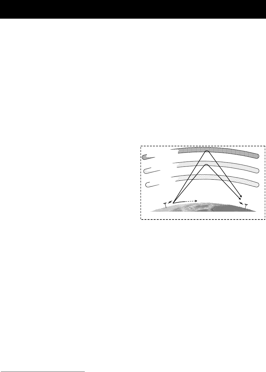
Appendix
11-23
11.5 Guide to MF/HF operation
Be aware of the following points when using the MF/HF radio equipment.
z Frequencies available for communication are always changing.
z Not all frequency bandwidths can always be used for communication.
z After sending the DSC test call to a coast station, you will not always receive the
acknowledgement.
1. About the MF/HF radio equipment
Although for ship MF/HF radio equipment the 1.6 MHz to 27.5 MHz frequencies are
normally available, select an appropriate frequency from the frequencies assigned to
your ship for communication. As noted below, the use of the appropriate frequency
depends upon the radio wave propagation characteristics of the ionosphere.
Therefore, not all frequency bands are available for communication even if the
equipment is functioning properly.
2. Special characteristics of MF/HF radio wave propagation
As shown in the figure to the right, the
major MF/HF radio waves used for
communications are terrestrial waves
(path 1) and waves reflected from the
ionosphere (paths 2 and 3). You can
communicate using waves reflected from
the ionosphere and the earth because
the effective communication range of
terrestrial waves is limited6.
The available range of frequencies for
communication depends upon the radio
wave propagation characteristics of the
ionosphere. They will also change dramatically depending on the position and
distance from the station, the season, the time, and the sunspot number (approx. 0 to
250) which changes every 11 years7.
3. Selecting communication frequencies
MF/HF band communication frequencies cannot be predetermined. However, you can
select frequencies referring to previous communications logs, the frequency transition
table in this chapter under "Selecting communication frequencies in the MF/HF band
(reference)", and the radio wave propagation image.
4. About DSC testing
DSC operation is prescribed as an international standard8 of the ITU and coast
stations that receive DSC test calls should acknowledge the calls. Responses may be
sent manually instead of automatically depending on the equipment at the coast
station. It may take longer than expected to receive the acknowledgement even if
your equipment is functioning properly and you have selected the proper
frequency.
6 You may experience skip zones where both terrestrial waves and waves reflected from the
ionosphere are unavailable at the end of the effective communication range of terrestrial
waves.
7 Radio wave propagation is affected by phasing, the Dellinger phenomenon, magnetic storms,
and atmospherics. Interference tends to be greater at night when radio waves can travel
greater distances.
8 ITU-R Recommendation M. 541
無線局 A
23
無線局 B
1
電離層 F1/F2層
電離層 E層
電離層 D層
地表
Ionosphere F1/F2 layer
Ionosphere E layer
Ionosphere D layer
Station A
Earth
Station B
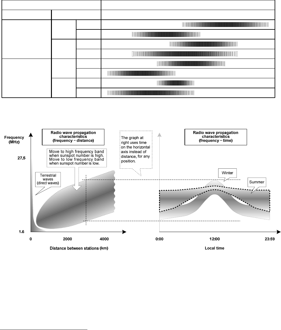
Appendix
11-24
Selecting communication frequencies in the MF/HF band (reference)
When communicating with the MF/HF radio equipment, select frequencies referring to the
frequency transition table and the radio wave propagation images (excluding the polar
latitudes) shown below9.
Example: When communicating with a station approximately 5000 km away at
around 12 pm in the winter with a sunspot number of 100, select
frequencies in the 18, 22, or 25 MHz bands for the best results.
¾ Frequency transition table
日中
夜間
冬
夏
冬
夏
遠距離
(例:5000km)
近距離
(例:1000km)
距離 季節と時刻 2M 4M 6M 8M 12M 16M 18M 22M 25M
周波数選択の目安
(太陽の黒点数 = 100の場合)
通信条件
日中
夜間
日中
夜間
日中
夜間
Transmissions conditions
Distance Season & time
Day
Winter Night
Day
Long distances
(e.g. 5000 km)
Summer Night
Day
Winter Night
Day
Short distances
(e.g. 1000 km)
Summer Night
Guideline for selecting frequency (for a sunspot count of 100)
¾ Radio wave propagation images
9 These are based on the prediction of HF radio wave propagations. Communication is not
guaranteed.

7ZPJD0604
电子信息产品有害物资申明
Japan Radio Company Limited
电子信息产品有害物资申明
日本无线株式会社
Declaration on toxic & hazardous substances or elements
of Electronic Information Products
名称
(Name)
: MF/HF Radio equipment
(Names & Content of toxic and hazardous substances or elements)
形式名
(Type)
: JSS 2250/2500
有毒有害物质或元素的名称及含量
名称
(N
ame
)
:
MF/HF
R
a
di
o equ
i
pmen
t
铅 汞 镉 六价铬 多溴联苯 多溴二苯醚
(Pb) (Hg) (Cd) (Cr6+)(PBB) (PBDE)
天线
(Antenna) ×○××××
形式名
(T
ype
)
:
JSS
-
2250/2500
部件名称
(Part name)
(Toxic and Hazardous Substances and Elements)
有毒有害物质或元素
()
船内装置
(Inboard Unit) ×○××××
外部设备(Peripherals)
・选择(Options)
・打印机(Printer)
・电
线类
(
Cables
)
×○××××
电线类
(Cables)
・手册(Documennts)
○:表示该有毒有害物质在该部件所有均质材料中的含量均在SJ/T11306-2006 标准规定的限量要求以下。
(Indicates that this toxic, or hazardous substance contained in all of the homogeneous materials for this part is below the requirement in
SJ/T11363-2006.)
×:表示该有毒有害物质至少在该部件的某一均质材料中的含量超出SJ/T11363-2006 标准规定的限量要求。
(Indicates that this toxic or hazardous substance contained in at least one of the homogeneous materials used for this part is above
the limit requirement in SJ/T 11363-2006.)
Management Methods on Control of Pollution from Electronics Information Products of the People's Republic of China
RE: 中华人民共和国电子信息产品污染控制管理办法
- 1 / 1 -

- 1/1 -
Marking with market circulation mark
According to the requirements of clause 20 of Technical Regulations about safety of Maritime
transport objetcs, approved by Resolution of the Russian Federation Goverment #620 dated
August 12, 2010 and requirements Technical Regulation of the Russian Federation Goverment
#623 dated August 12, 2010 navigation & radiotelephone equipment should be marked by
company – manufacturer with market-circulation mark the way it is determined by Legislation of
the Russia federation on technical regulation.
According to the airticle 27 PZ No184 –FZ of Federal Law about Technical Regulation dated
December 12, 2002 and Resolution of the Russian Federation Goverment dated 19.11.03
No0696 navigation equipment has an appropriate marking. The marking can be perfomed by one
of four variants, depending on surface colour of equipment.
The images should be grey scale and should contrast against the surface colour (ref. to the
Resolution of the Russian Federation Goverment No696 <<About market circulation mark>>
dated November 19, 2003).
The marking of Radio and navigational equipment should be done by the manufacturer (supplier)
according to the clause 2 of the article 27 of the Federal Law No.184 –FZ << About technical
Regulation>> and should be applied right to device surface.