Japan Radio NJJ-105 Ground Penetrating Rader User Manual DC50 NJJ 105
Japan Radio Co Ltd. Ground Penetrating Rader DC50 NJJ 105
usermanual
NJJ-105
Handy Search
Users Guide
i
Preface
Thank you very much for purchasing this JRC NJJ-105 Handy Search (hereafter
called this product).
The NJJ-105 Handy Search nondestructively locates, detects, and displays the
depths and positions of reinforcing steel bars in reinforced concrete structures.
●Before starting to use the NJJ-105 Handy Search, read through this instruction
manual carefully to learn correct operations and ensure correct and trouble-free
operations.
●Keep the instruction manual handy for reference. Refer to the manual when
facing unknown things or when experiencing troubles during operation.
DC50-NJJ-105
First edition January 2011
ii
Before Operation
Pictorial Indication
Various icons are indicated in this manual and are labeled on this
product to ensure your safe and correct operations and to prevent any
danger to you and/or other persons and any damage to your property
during operation. Such indications and their meanings are as follows.
Please understand them before reading this manual.
Examples of Pictorial Indication
●JRC assumes no liability for any damage (such as damage caused
to reinforcing steel bars, electrical pipes, gas pipes, etc.) arising
from scan results using this product.
●JRC assumes no liability for any damage arising from the
disappearance of scan results stored in CF memory.
* Windows is a registered trademark or a trademark of Microsoft Corporation in
United State and other countries.
*CompactFlash (CF) is a registered trademark or SanDisk Corporation.
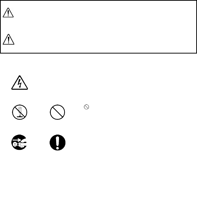
WARNING
This indication is shown where any person is supposed to
be in danger of being killed or seriously injured if this
indication is neglected and this product is not operated
correctly.
CAUTION
This indication is shown where any person is supposed to
be injured or any property is supposed to be damaged if
this indication is neglected and this product is not
operated correctly.
Electric
shock
A △ mark indicates CAUTION (including DANGER and
WARNING). Detailed content of the specific CAUTION
(“Electric Shock” in the example on the left.) is shown in
the mark.
Disassembling
Prohibited
Prohibition
A mark indicates prohibition. Detailed content of the
prohibited action (“Disassembling Prohibited” in the
example on the left.) is shown in the mark.
Disconnect the
power plug
Instruction
A ●mark indicates instruction. Detailed content of the
instruction (“Disconnect the power plug” in the example on
the left.) is shown in the mark.
iii
Precautions for Use
WARNING
Do not use any battery pack other than the recommended battery packs.
Doing so may cause fire, electric shock, or breakdown.
Do not short-circuit the terminals of the battery charger or battery pack. Doing
so may cause fire, explosion, or breakdown.
Do not insert metallic or flammable objects into the CF memory slot. Doing so
may cause injury, fire, electric shock, or breakdown.
Do not disassemble, modify, heat, or place battery pack in fire. Doing so
may cause fire, explosion, or breakdown.
Do not use any charger other than the recommended battery charger to
charge the battery pack. Doing so may cause fire, electric shock, or
breakdown.
Do not disassemble, modify, or repair this product by yourself. Doing so may
cause fire, electric shock, or breakdown.
If the power cord is damaged (exposure of the core wire, open circuit failure,
or break in the sheath), contact our nearest branch office (See Section 9),
sales outlet, or service station for a replacement power cord. Use of a
damaged power cord may cause fire or electric shock.
Do not connect/disconnect the power plug by wet hands. Doing so could
cause an electric shock.
Do not use (place) this product in a location where it is exposed to flammable
or corrosive gas. Doing so could cause fire, personal injury, or breakdown.
This product has a waterproof construction but must not be dipped in water.
Do not expose this product to water or moisture, and do not use it in rainy
weather. Doing so could cause an electric shock or breakdown.
Stop using this product immediately when a sign of malfunctioning is
detected, and follow only the detailed procedure in this instruction manual. If
it cannot be restored to normal operation, contact our nearest branch office
(See Section 9), sales outlet, or service station. Use of this product in an
abnormal state could cause fire or breakdown.
Should this product emit an abnormal sound, odor, or smoke, immediately
turn off the power switch, remove the battery pack, disconnect the power
plug from the socket outlet, and contact our nearest branch office (See
Section 9), sales outlet, or service station. Use of this product in an abnormal
state could cause fire, electric shock, or breakdown.
Before disposing of the used lithium ion battery, insulate the charging
terminals by taping or the like. Otherwise, the battery could cause fire or
explosion if short-circuited.
iv
CAUTION
Judge the scan result with considering the depth sensing capability of this
product. Since the depth sensing capability of this product is subject to the
conditions of the object of investigation, judging the scan result with no
consideration of the depth sensing capability may cause the cutting of rebar.
Put your hand through the hand strap and hold this product. Dropping of this
product may cause an accident such as a device breakdown or personal
injury.
When disconnecting the power cord, hold the plug. Pulling the power cord by
itself may cause cord damage, fire, or electric shock.
Do not place this product on an unstable place such as a wobbly table or
sloping surface. Doing so may cause a personal injury or breakdown when it
drops or falls.
Do not use (place) this product in a humid or dusty location, or a location
where water, oil, or chemical may splash onto this product. Doing so may
cause fire, electric shock, or breakdown.
Do not use (place) this product in a location where it is subject to vibration or
shock. Doing so may cause a personal injury or breakdown.
When loading/unloading printing paper, be careful not to cut or jam your
fingers in the printer.
Point the antenna surface in the direction of the object (concrete) while you
are performing a probe. If it is pointed into the air or otherwise unsuitable
direction, it can cause malfunction of other equipment or other such accidents.
Do not use this product in the vicinity of a radio or TV set. Doing so may
cause noise or poor reception such as disturbance of television pictures.
Doing so also adversely affects the depth sensing capability of this product,
and may cause the cutting of reinforcing steel bars.
Do not use this product near a cell phone or transceiver that transmits
electromagnetic waves. Electromagnetic waves from the cell phone or
transceiver may adversely affect the depth sensing capability of this product,
and may cause the cutting of reinforcing steel bars.
When this product is used for probing on a road, take safety precautions such
as providing guard fences to prevent traffic accidents.
v
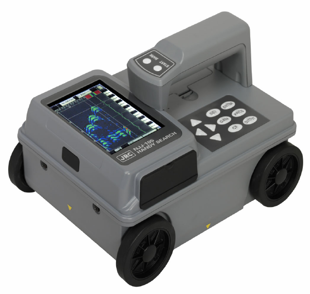
Appearance
vi
Table of Contents
Preface i
Before Operation ii
Precautions for Use iii
Appearance v
Glossary of Terms ix
1 Description of Equipment 1
1.1 Function 1
1.2 Features 3
1.3 Configuration 5
1.4 Overall System Diagram 6
1.5 Configuration 7
2 Parts Names and Functions 8
2.1 Handy Search NJJ-105 8
2.2 Example of the Scan Screen 12
2.2.1 Scan screen example (during scanning) 12
2.2.2 Scan screen example (during not scanning) 14
2.3 Parameter setting screen 16
2.3.1 disp. color 16
2.3.2 disp. direction 16
2.3.3 disp. mode 17
2.3.4 amplitude 18
2.3.5 X-axis 19
2.3.6 depth 19
2.3.7 date/time 19
2.3.8 data No. 20
2.3.9 Folder 20
2.3.10 dist. adj. 21
2.3.11 output 21
2.3.12 disp. range 22
2.3.13 XY.unit 22
2.3.14 Character Mode 22
2.3.15 Search PRCS 22
2.3.16 Scroll.speed 23
2.3.17 default 23
2.3.18 disp.color. setting 23
2.3.19 disp. direction. setting 23
vii
2.3.20 disp.mode. setting 24
2.3.21 Amplitude. setting 24
2.3.22 X-axis. setting 24
2.3.23 depth. setting 24
2.3.24 output. setting 25
2.3.25 disp. range. setting 25
2.3.26 gain. setting 25
2.3.27 Marker 25
2.4 CF Control screen 26
3 Operating Method 27
3.1 Scan preparation 29
3.2 Scanning 36
3.2.1 Power-on procedure 36
3.2.2 Scanning 36
3.2.3 Sensitivity 38
3.2.4 Antenna Mark 38
3.2.5 Real time manual deduction processing 39
3.3 Operation while not Scanning 41
3.3.1 Mode switching 41
3.3.2 Sensitivity switching 42
3.3.3 Cursor operation 42
3.4 Image Processing 48
3.4.1 Fixed surface wave processing 48
3.4.2 User surface wave processing 49
3.4.3 Deduction processing 51
3.4.4 Manual surface wave processing 53
3.4.5 Average wave processing 55
3.4.6 Peak processing 55
3.4.7 Original image 57
3.5 How to determine depths and sample scan data 58
3.6 External output methods 59
3.6.1 Printer output 59
3.6.2 Data saving in CF memory 61
3.7 CF Control Screen 67
3.7.1 Displaying the thumbnail images of saved data 68
3.7.2 Reading saved data 68
3.7.3 Deleting a saved data 71
viii
3.7.4 Deleting all saved data under the selected folder 71
3.7.5 Deleting all saved data in the CF memory 73
3.8 Power-off Procedure 74
3.9 Clearing up this product and accessories 74
3.10 About the battery pack and charger 75
3.10.1 Battery pack BP-3007 series 76
3.10.2 Charging Device BC-3008 series 78
4 Theory 79
4.1 Principle of Operation 79
4.2 Applicable Conditions 80
5 Maintenance Inspection 81
5.1 Daily Inspection 81
5.2 Daily Maintenance 81
5.3 Troubleshooting 82
6 After-sales Service 84
7 Disposal 85
7.1 Disposal of Used Battery Pack 85
7.2 Disposal of this product 85
8 Specification 86
8.1 Handy Search NJJ-105 86
8.2 Battery pack BP-3007 series 87
8.3 Battery charger BC-3008 series 87
9 Where to Contact 88

ix
Glossary of Terms
A-mode Displays received waveform as it is. The conditions of concrete directly
underneath this product are displayed as reflected waveform in real time.
B-mode
Displays the vertical cross section of a scan point by gradating the
reflected waveform shown in A-mode according to reflection intensity and
continuously displaying it.
BA-mode Displays both B-mode and A-mode images at the same time.
Real time
auto surface wave
processing
Image processing to automatically remove the unwanted waves reflected
from the concrete surface during scanning by using the internal fixed
surface wave data and shows only the reflected wave from rebar etc.
Real time
manual deduction
processing
Image processing used in the case where the unwanted waves reflected
from the concrete surface can not be fully removed by using the real time
auto surface wave processing and the unwanted waves remain as the
form of stripes in the scan result.
In this Image processing, an arbitrary line is designated while scanning.
The data of the designated line is subtracted from the scan result data,
and the reflected wave from the concrete surface is automatically
removed. Thus, only the reflected waves from rebar etc. are shown.
Real time
auto user
surface wave
processing
Image processing to automatically remove the unwanted waves reflected
from the concrete surface during scanning by using the surface wave data
which are defined by the user and stored in the product and shows only
the reflected wave from rebar etc.
Fixed surface
wave
processing
Image processing to remove the unwanted waves reflected from the
concrete surface by using the internal fixed surface wave data and shows
only the reflected wave from rebar etc.
User surface wave
processing
Image processing to remove the unwanted waves reflected from the
concrete surface by using the surface wave data which are defined by the
used and stored in the product and shows only the reflected wave from
rebar etc.
Deduction
processing
Image processing to remove the stripe reflected waves throughout the
entire depth, such as reflected waves from the concrete surface and from
the rear surface etc. In this processing, an arbitrary line in the scan result
is designated and the designated line is subtracted from the scan result
data and only the reflected waves from rebar etc. are shown.
Manual
surface wave
processing
Image processing to remove the unwanted waves reflected from the
concrete surface by using the surface wave data of the disignated
position in the search results and shows only the reflected waves from
rebar etc. In this processing, an arbitrary line is designated from scan
results. The surface portion of the designated line is subtracted from the
scan result data, and the reflected waves from the concrete surface is
removed.
Average wave
processing
Image processing to remove the stripe reflected waves throughout the
entire depth, such as reflected waves from the concrete surface and from
the rear surface etc. In this processing, the averaged waveform of the
entire scan results data are calculated and is subtracted from the scan
result data, and only the reflected waves from rebar etc. are shown.
Peak processing
Image processing that shows only the waveform of the first peak on the
+side of the scan result. This enables removal of multiple reflected
signals and only displays the upper rebar.

x
Glossary of Terms (Continued)
Original image Restores the image processed result to the original state and displays
unprocessed raw data.
Distance feed
scan
Scan method that performs scanning in accordance with Handy Search's
traveling distance, using the distance detector mounted on the wheels of
this product.
Time feed scan Scan method that performs B-mode scanning at preset time intervals,
regardless of movement of this product.
Relative dielectric
constant
Object-specific coefficient. The radio wave propagation velocity changes
with the relative permittivity (dielectric constant). Therefore, the wave
propagation velocity and search depth change based on the relative
permittivity of the concrete. Calculation error of search depth can be
reduced by setting a depth calibration value.
- 1 -
1 Description of Equipment
This product is indispensable for repairing/rebuilding and maintaining reinforced
concrete structures using its accurate and speedy diagnostic technology.
This product (concrete internal probe vehicle) radiates electromagnetic waves
through the surface of concrete and receives reflected signals from objects found
inside such as reinforcing steel bars, cavities, or other objects that have different
electrical characteristics from concrete. Object position and depth are then displayed
and recorded as image data.
CAUTION
Judge the scan result with considering the depth sensing capability of this
product. Since the depth sensing capability of this product is subject to the
conditions of the object of investigation, judging the scan result with no
consideration of the depth sensing capability may cause the accidental cutting
of rebar.
1.1 Function
Table 1-1 shows functions and performances of this product.
Table 1-1 Functions and Performances of this product
No. item Functions and Performances
1 Search method Electromagnetic wave radar method
2 Search object Rebar (reinforcing steel bar), Polyvinyl-chloride pipe,
Cavity, etc.
3 Search depth 5 to 300mm for concrete having a relative dielectric
constant = 6.2 and the top rebar of diameter ≧ 6mm
4 Depth resolution Approx. 1 mm at the display range setting of Shallow
Approx. 2 mm at the display range setting of Deep
5
Horizontal
discrimination
resolution
≧ 75mm for the scanned object located at depth < 75mm
≧ Depth of the scanned object for the object located at
depth ≧ 75mm
※Typical performance for the reference concrete:
This product allows the user to discriminate between two
rebars located respectively at depth 75mm and 175mm and
at the interval of 40 mm.

- 2 -
Table 1-1 Functions and Performances of NJJ-105 (Continued)
No. item Functions and Performances
6 Maximum search
depth 2.5mm
7 Maximum scan
distance 15m
8 Display mode B-mode (Vertical Cross Section) and BA-mode(Vertical
Cross Section and Reflection Waveform Graph)
During scanning:
Real time auto surface wave processing, Real time manual
deduction processing, and Real time user surface wave
processing
9 Image processing After scanning:
Fixed surface wave processing, User surface wave
processing, Deduction processing, Manual surface wave
processing, Average wave processing, Peak processing,
and Original image
10 Depth calibration 2.0 to 20.0, 0.1 step and time
11 Maximum scan
speed
Approx. 40cm/s, Alarm capability furnished for the over
speed scanning
12 Control functions Display marker(Maximum 42 points), Battery capacity
indicator, and Display inverse video
13 Data output
functions
Dedicated printer (Option, Monochrome print) and
CF Memory (Approx. 200 scan data of 15m distance and
binary format can be stored in the 1GB CF memory)
- 3 -
1.2 Features
This product has the following features:
(1) The material of the object to be scanned can be either metallic or non-metallic
Reflected electromagnetic waves are generated at an interface when the
electrical property of an object is different from that of concrete. Thus, this
product can probe polyvinyl-chloride pipes and cavities (dependent on the
position and size) as well as the reinforcing steel bars. Note that
polyvinyl-chloride pipes and cavities echo weakly in compared with the
reinforcing steel bars.
If a polyvinyl-chloride pipe or cavity is near or below the reinforcing steel bars,
the reflected signals from the polyvinyl-chloride pipe or cavity may not be
obtained due to the strong reflected signals from the reinforcing steel bars. Thus,
care should be taken when you make a judgment on the scan result.
(2) Detects rebars that cross the scanning direction
Rebar that cross the scanning direction transmit a large magnetic wave
reflection. On the other hand, rebar that is parallel to the scanning direction
transmit a smaller magnetic wave reflection. Even if scanning is performed
above rebar that is parallel to the scanning direction, this product can still detect
any rebar that is crosswise to the scanning direction.
(3) Obtaining continuous scan results
The scan result are obtained as a representation of the vertical cross section
of the inside of concrete. Thus, a comprehensive view of the internal concrete
conditions can be obtained.
(4) Obtaining scan results at the site
This product does not need to be secured to the surface of concrete.
Scanning is carried out while this product is moved, and scan results
concerning the internal conditions of the concrete can be provided immediately.
(5) Saving and reading scan data
Using a CF memory, scan data can be saved and reopened (maximum of
roughly 50 sets of data can be saved in text format for a depth of 15 m using a
512 MB CF). The data can also be loaded from the CF memory into a PC by
using a memory reader or the like.
(6) Printing without cable connection
This product is equipped with IrDA, therefore, printing can be performed
without using a cable using a DPU-3345 series printer.
However, the IrDA optical receptors for this product and the printer must be
set facing each other at a distance of 50 ~ 500 mm (without any obstacles
between them).
- 4 -
(7) Performing real time automatic surface wave processing
Internal fixed surface wave data is used to automatically remove the wave
reflected from the concrete surface during scanning enabling the showing of the
reflected wave from rebar.
Furthermore, surface wave processing can be switched to processing that
uses scan data surface waves during scanning (real time manual deduction)
enabling highly accurate surface processing.
(8) Displaying the data of an arbitrary point after scanning (scroll function)
This product can store 15m worth of data at a time and display the data of
arbitrary points continuously.
(9) Changing sensitivity and performing image processing for scan data
This product can display scan results after changing sensitivity or performing
image processing (manual surface wave processing, peak processing, original
image, fixed surface wave processing, or deduction processing). Thus,
performing a scanning again with a new sensitivity setting is not necessary.
(10) A marker can be displayed in the scan results using the cursor marker function.
A maximum of 42 cursor markers can be placed in the scan results to display
the scan position and depth of the marker.
(11) Providing the screen inversion function
Screen inversion function is available. In case of scanning from right to left on
a wall surface, the display on the screen is upright (normal). In the case of
scanning left to right, the display will be inverted.
Therefore, the user can achieve the correct display by performing the scan
either right to left or left to right.
(12) Recording of date and settings
The main unit records the date and settings (data number, sensitivity, etc.)
using a backup function. When data is output, the date and settings are
recorded.
(13) Compact and light weight
This product weighs only about 1.1 kg, so it is easy to operate.
(14) Operating with the battery pack and commercial power supply
This product can operate with the battery pack for about 1.5 hours (at normal
temperature). It can also operate with the commercial power supply when an AC
adapter (optional) is used.

- 5 -
1.3 Configuration
(1) Standard components
Table 1-2 shows the standard configuration of the Product NJJ-105.
Table 1-2 Standard Components
Name Model Number Quantity Remarks
Handy Search NJJ-105 1
Battery pack BP-3007 series 1
Battery charger BC-3008 series 1
AC cable CB-JP05 series 1 For the battery
charger
Hand strap H-7ZYMD0018 1
CF memory TS1GCF80 1 Memory size: 1GB
Storage box H-7ZYMD0017 series 1
Users Guide DC50-NJJ-105 1 This manual
Quick instruction sheet DC60-NJJ-105 1
License agreement for software DC20-NJJ-105 1
(2) Options
Table 1-3 shows optional products that are provided in addition to the
standard components.
Table 1-3 Options
Name Model Number Remarks
Battery
charger set for
the Handy
Search (*1)
CBK-154
For the battery pack BP-3007 series:
Set configuration: Adapter (PWC-L07 series)
AC cable (CB-JP05 series)
Printer set CMZ-303
Set configuration: Printer (DPU-S445 series)
Battery pack (BP-L0720 series)
Printing paper (TP-341series)
AC adapter set
(*1) CBD-2485 Set configuration: AC adapter (PW-0904 series)
AC cable (CB-JP04) series
Battery
charger set for
the printer (*1)
CBK-254
For the battery pack BP-L0720 series
Set configuration: Adapter (BC-3008 series)
AC cable (CB-JP04 series)
Battery pack
(*1) BP-3007 series For the Handy Search (NJJ-105)
Battery pack BP-L0720
series
For the printer DPU-S445 series
Printing paper
(*1) TP451C Set of 10 rolls
(*1): Are common for NJJ-95 series option printer DPU-3445.
- 6 -
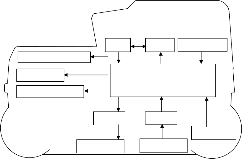
1.4 Overall System Diagram
Figure 1-1 shows the overall system diagram of this product.
Figure 1-1 Overall System Diagram
LCD
CPU Memory
Distance
Detector
Op key
Control section
IrDA Trans
CompactFlash memory
Trans Receive
Rec. antenna
Trans antenna
- 7 -
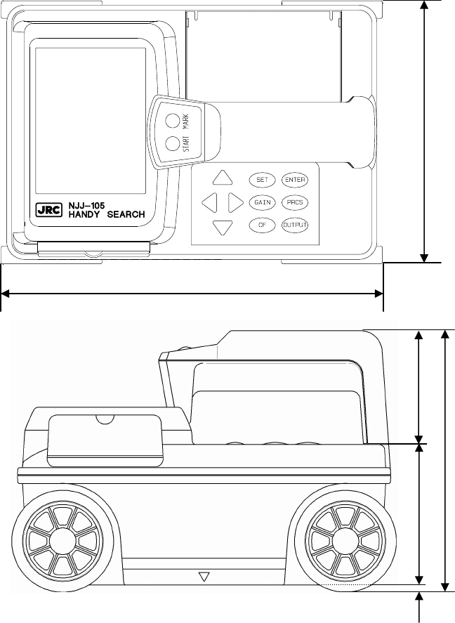
1.5 Configuration
Figure 1-2 shows the external views of this product.
Figure 1-2. Handy Search NJJ-105 external dimensions diagram
Top view drawing
64
79
4
147
Side view drawing
216
149
- 8 -
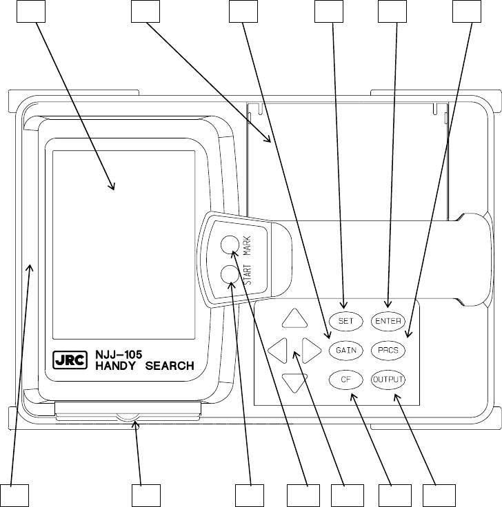
2 Parts Names and Functions
2.1 Handy Search NJJ-105
This section shows the operation panel of this product and explains the functions for each part.
1 2 3 4 5 6
7 8 9 10 11 12 13
Figure 2-1 Top View
- 9 -
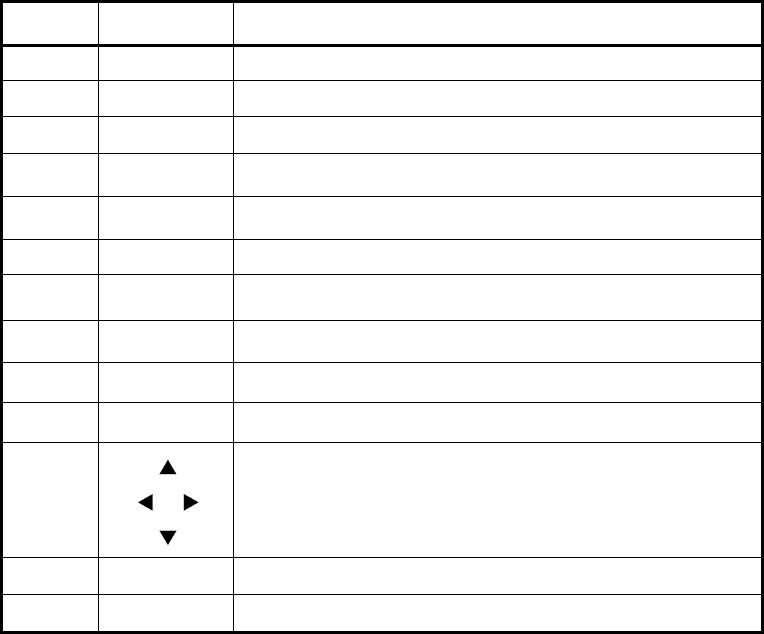
Table 2-1 Main Functions of Parts on this product
Number in
Square Label Function
1 (None) LCD (liguid crystal display) screen
2 (None) Battery holder
3 GAIN Sets the sensitivity
4 SET Sets each of the parameters.
5 ENTER
Decision key for start of image processing and various types of
selection.
6 PRCS Switch to image processing mode.
7 (None) IrDA optical receptor for communicating with the printer
8 (None) CF memory slot
9 START Starts/stops the scanning.
10 MARK Displays a marker on the scan screen.
11
Used for movement of cursor and screen and making changes to the
various parameters.
12 CF Switch to the CF control screen.
13 OUTPUT Key for outputting data.
- 10 -
8 14 15
Figure 2-2 Side View
16 17 14 18
Figure 2-3 Rear View
NJJ
-
105

- 11 -
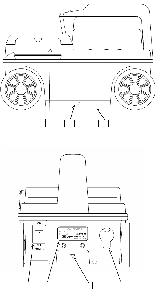
Table 2-2 Functions of Parts on the Side and Rear Panel
Number in
Square Label Function
14 V Mark indicating the scan position.
15 (None) Antenna face to radiate and receive electromagnetic waves
16 POWER ON OFF Turns power on and off.
17 (None) Equipment nameplate
18 (None) Connector for AC adapter
- 12 -
2.2 Example of the Scan Screen
Describes each display on the scan screen.
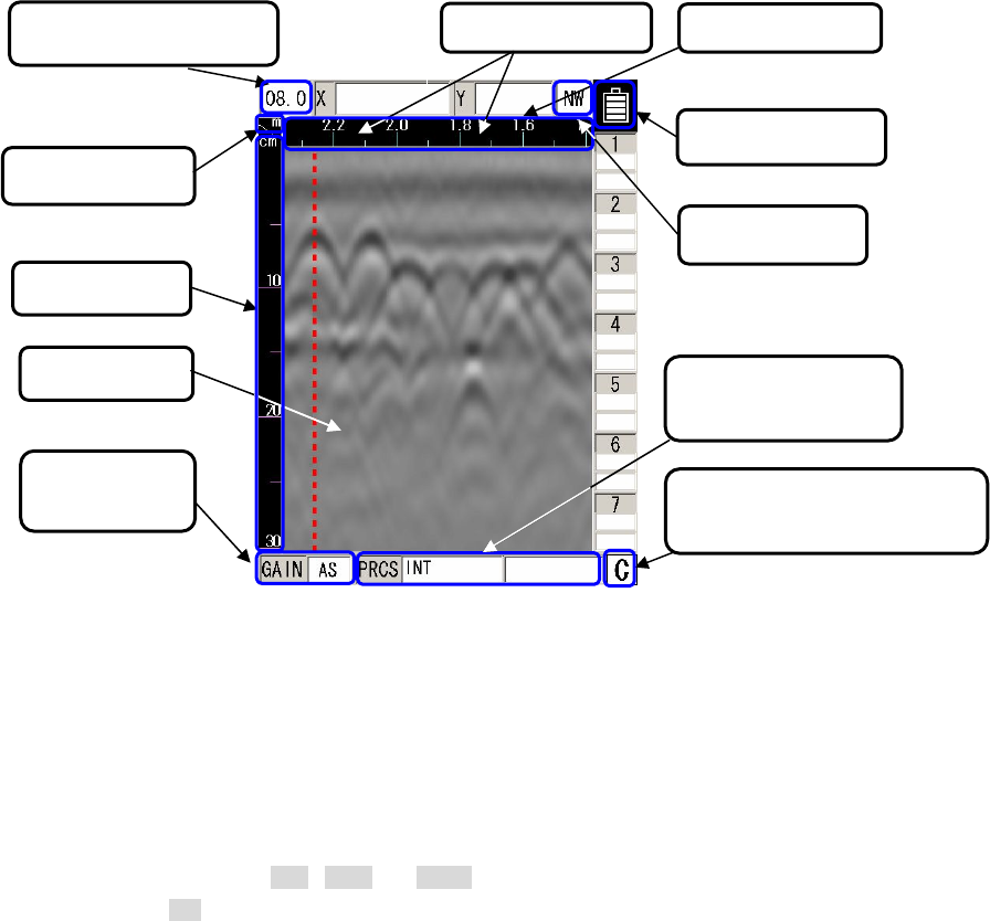
2.2.1 Scan screen example (during scanning)
An example of a scan screen (during scanning) is shown in Figure 2-4.
Figure 2-4 Scan screen example (during scanning)
(1) Depth calibration value
Displays the depth calibration value set at the parameter setting screen. See Section
2.3.6 depth to set the depth calibration value.
(2) Scan mode
Displays the scan mode set at the parameter setting screen. When selecting the
distance feed scan, m , cm , or mm is displayed. When the time feed scan is
selected, s is displayed. See Section 2.3.5 X-axis to set the scan mode.
▼ ▼
(2)Scan mode
(6)Antenna Mark (7)Distance gauge
(1)Depth calibration value
(3)Depth gauge
(4)Fixed cursor
(5)Sensitivity
display
(8)Battery meter
(10)Image processing
dis
p
la
y
(11)External data output
dis
p
la
y
(9)Display range
- 13 -
(3) Depth gauge
Displays a depth gauge. The depth gauge changes based on the depth calibration
value.
(4) Fixed cursor
Is a cursor fixed at the specified position that is used to designate surface waves used
for real time manual deduction processing. See Section 3.2.5 Real time manual
deduction processing for more details.
(5) Sensitivity display
Displays the scan sensitivity setting. See Section 3.2.3 Sensitivity for more details.
(6) Antenna mark
Displays the position of antenna marks. See Section 3.2.4 Antenna mark for how to
use the antenna mark.
(7) Distance gauge
Displays the distance moved while performing a scan.
(8) Battery meter
Displays the remaining power in the battery pack.
(9) Display range
Displays the display range set at the parameter setting screen. See Section 2.3.11
Display range for mode details.
(10) Image processing display
Displays the selected image processing performed during scanning. See Section 3.4
Image processing for how to perform the image processing.
(11) External data output display
Displays the destination of the external data output set at the parameter setting screen.
See Section 2.3.10 External data output for more details.
- 14 -
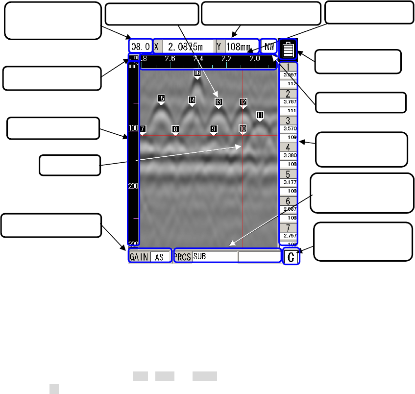
2.2.2 Scan screen example (during not scanning)
An example of a scan screen (not during scanning) is shown in Figure 2-5.
Figure 2-5 Sensing test screen example (not during sensing)
(1) Depth calibration value
Displays the depth calibration value set at the parameter setting screen. See Section
2.3.6 depth to set the depth calibration value.
(2) Scan mode
Displays the selected scan mode set at the parameter setting screen. When selecting
Distance feed scan, m , cm , or mm is displayed. When selecting Time feed scan,
s is displayed. See Section 2.3.5 X-axis to set the scan mode.
(3) Depth gauge
Displays a search depth gauge. The search depth gauge changes based on the depth
calibration value.
(4) Cursor
Is a criss-cross cursor that is used to place a cursor marker on the scan screen, to
scroll the scan screen, and to designate the position of the A-mode waveform displayed
on the B-mode display.
(2)Scanning mode
(7)Cursor Coordinates (8)Distance gauge
(1)Depth calibration
value
(3)Depth gauge
(4)Cursor
(5)Sensitivity display
(9)Battery meter
(12)Image processing
display
(13)External output
display
(10)Display range
(11)Cursor mark
coordinates
(6)Cursor Mark
- 15 -
(5) Sensitivity display
Displys the sensitivity setting. See Section 3.3.2 Sensitivity switching for the method to
switch sensitivity.
(6) Cursor marker
Displays the position of cursor markers. See Section 3.3.3 Cursor operation for how to
display and erase the cursor marker.
(7) Cursor coordinates
Displays the coordinates of the cross point of the cursor described in the item (4)
above. The distance moved is shown in the X field and depth in the Y field.
(8) Distance gauge
Displays the distance gauge in the direction the scan is performed. This gauge
displays the distance this product has moved.
(9) Battery meter
Displays the remaining power in the battery pack.
(10) Display range
Displays the display range set at the parameter setting screen. See Section 2.3.11
disp. range for the method to set the display range.
(11) Cursor marker coordinates
Displays the coordinates of the cursor marker described in the item (6) above. Below
each of the marker numbers, the movement distance (X) is shown in the first row and the
depth (Y) is shown in the second row.
The movement distance value is displayed with truncating 0.5mm order. Therefore
when the least significant number is 2 or 7, treat it as 25 or 75, respectively.
Example: when the cursor marker coordinate X = 1.002, the actual marker coordinate
is 1.0025.
(12) Image processing display
Displays the selected image processing which is performed to the scan results. See
Section 3.4 Image processing for more details.
(13) External data output display
Displays the selected external data output (output destination) set at the parameter
setting screen. See Section 2.3.10 External data output for how to use the external data output.
- 16 -
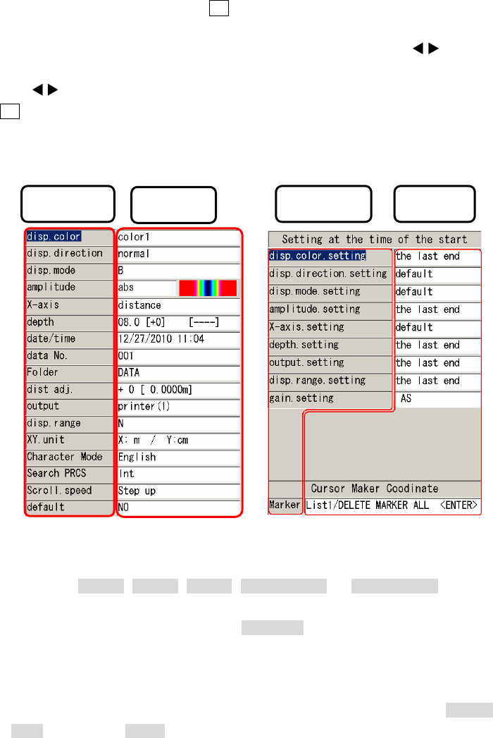
2.3 Parameter setting screen
The parameter setting screen Is used to see the current setting and to change the setting for each
parameter. To access this screen, press the 4 SET key while the scan is stopped, then the parameter
setting screen shown in Figure 2-6 appears. To change the setting of a parameter, move the cursor
(inverse video line) on the parameter by pressing the ▲▼ cursor keys, press the cursor keys to
enter into the setting field of the parameter. Select a desired setting by pressing the ▲▼ cursor keys, then
press the cursor keys to exit from the setting field. To exit from the parameter setting screen, press
the 4 SET key again.
Regarding the operation to read out the scan data in CF memory, see Section 3.7.2 Reading saved
data.
Figure 2-6 Parameter setting screen
2.3.1 disp. color
You can specify the display color used in the B-mode display by this parameter. The available
settings are Color1 , Color2 , Color3 , Monochrome1 , or Monochrome2 . Set a desired
setting to this parameter in accordance with the method described in section 2.3. When changing
the setting, the color bar displayed at the amplitude setting field automatically changes and
shows visually the selected display color.
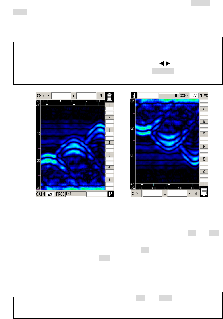
2.3.2 disp. direction
You can specify the display direction by this parameter. The available settings are normal and
invert . When setting invert to this paramter, the screen display is inverted on the scan screen
Parameter Setting Parameter Setting
- 17 -
while scanning to the right or to the left. The examples of the screen display for normal and
invert settings are shown in Figure 2-7. Set a desired setting to this parameter in accordance with
the procedure described in section 2.3.
• The direction of the image data output to the printer (optional) follows the setting of
the display directcion . To output image data to the printer always in the same
direction, set the same setting to the display direction.
• While the screen display is inverted, the cursor keys ▲▼ work in the opposite
direction. (They work in the same direction as when normal is selected for the
display direction.)
Screen display direction [Normal] Screen display direction [invert]
Figure 2-7 Screen display inversion
2.3.3 disp. mode
You can specify the display mode by this parameter. The available settings are B and BA .
This product supports two display modes of B-mode (vertical cross section) and BA-mode (vertical
cross section and reflected waveform display). When setting B to this parameter, the scan result
is displayed in the B-mode. When setting BA to this parameter, the scan result is displayed in the
BA-mode. Set a desired setting to this parameter in accordance with the procedure described in
section 2.3.
• When the display mode is switched between B and BA after scanning, the
data scanned in the B-mode is displayed in the BA-mode, and the data scanned in
the BA-mode is displayed in the B-mode. See Section 3.3.1 Mode switching.
Remarks
Remarks
- 18 -
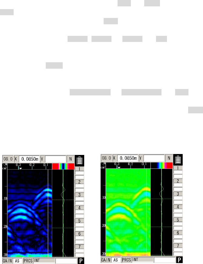
2.3.4 amplitude
You can specify the zero axis of the A-mode waveform and the color gradation used in the
B-mode display by this parameter. The available settings are abs and offset .
The abs sets the zero axis of the A-mode waveform (absolute amplitude) at the
vertical center line in the A-mode diaply, and the offset sets the zero axis of the A-mode
waveform (offset amplitude) at the left edge of the A-mode display.
When the display color is set to Color1 , Color2 , or Color3 , the abs uses the color
gradation in the B-mode display which changes the drawing color between Black → Indigo → Green
→ Yellow → Red as the absolute amplitude of the A-mode waveform increases as shown in Figure
2-8 Abosolute value. The offset uses the color gradation changing the drawing color between
Black → Indigo → Green → Yel low → Red as the offset amplitude of the A-mode waveform
increases as shown in Figure 2-8 Offset.
When the display color is set to Monochrome1 or Monochrome2 , the abs uses
the color gradation in the B-mode display which changes the drawing color between White
→ Gray → Black as the absolute amlitude of A-mode waveform increases. The offset
uses the color gradation changing the drawing color between White → Gray → Black as
the offset amlitude of the A-mode waveform increases.
Set a desired setting to this parameter in accordance with the procedure described in section 2.3.
Absolute value Offset
Figure 2-8 Gradation

- 19 -
2.3.5 X-axis
You can specify the scan mode by this parameter. The available settings are distance (distance
feed) and time (time feed). When distance is selected, this product scans and displays the
scan result in units of 2.5 mm in the B or BA-mode display with synchronizing the wheels' moving
distance. When time is selected, this product scans and displays the scan result at 50 ms
intervals in the B or BA-mode display, regardless of the wheels' moving distance. Set a desired scan
mode to this parameter in accordance with the procedure described in section 2.3.
2.3.6 depth
You can specify the depth calibration value (correction constant used for the depth calibration) by
this parameter. Enter the relative dielectric constant of the concrete being scanned to this parameter.
For the relative dielectric constant, refer to Glossary of Terms.
This product corrects the depth guage by using the depth calibration value (relative dielectric
constant of the concrete) entered in this parameter. The relative dielectric constant depends on the
condition (such as moisture content) of the concrete being scanned. Therefore the more difference
between the actual relative dielectric constant of the concrete and the entered value, the more the
depth error. Set an appropriate value to this parameter in accordance with the procedure described
in section 2.3.
In order to reduce the depth error, perform the depth calibration before the scanning by
performing the following procedure. Scan the object whose actual depth is known (Ex. the rebar with
a known depth) and detect the depth of the object. Then adjust the depth calibration value so as the
depth value displayed in the scan result matches the known depth. If the object with the known
depth is not avaialble and the relative dielectric constant of the concrete is unclear, it is
recommended to set 08.0 (+0) to this parameter.
• Each interval between neighboring two scales on the depth gauge is not same. Use
the depth value (Y) displayed at the cursor coordinates or cursor marker coordinates.
• The right hand side of the display field for the depth calibration value displays the
depth value (Y) at the cursor position.
2.3.7 date/time
You can set the date and time by this parameter. This product keeps and updates the date and
time in an internal non-volatile memory powered by a built-in rechargeable button-type lithium battery.
Set the correct time and date to this parameter in accordance with the procedure described in
section 2.3.
Remarks

- 20 -
2.3.8 data No.
You can specify the data number for the external output dat by this parameter. The scan result
data is recorded and numbered when being externally output. This parameter displays the current
data number of the output data, and the data number (Data No.) in this parameter is incremented
each time when the data is recorded and output. Set a desired data number to this parameter in
accordance with the procedure described in section 2.3.
• When the data are recorded again, it can be easily managed by changing the value
of the data No.
2.3.9 Folder
You can specify one folder among 10 predefined folders in the CF memory by this parameter.
The file operation (saving, reading, and deleting the scan data file) is performed under the specified
folder in the CF memory. The available settings are DATA , DATA02 , --- , DATA10 . Set a
desired setting to this parameter in accordance with the procedure described in section 2.3.
Remarks
• When using a blank CF memory (which does not have any folders of DATA , DATA02 , --- ,
DATA10 ), insert the CF memory into this product and cycle the power of the product. Then
this product creates 10 folders automatically in the CF memory. When the CF memory has
only DATA folder, cycling the power of this product creates 9 folders of DATA02 , --- ,
DATA10 automatically.
• Regarding the data save/recall operation of the scan data in CF memory, see Section 3.6
External output methods and Section 3.7 CF Control Screen.
Remarks
- 21 -
2.3.10 dist. adj.
You can specify the distance correction constant by this parameter. This product determines its
scanning distance using the number of rotations of the wheel. Thus, wear of the wheels causes error
in determining the scanning distance. To remove erro in the scanning distance, this product
compensates the detected distance by using the distance correction constant set to this parameter.
If the scanning distance has error, enter the correct distance correction constant to this parameter by
performing the following procedure.
Example of the scanning distance compensation:
a) Perform a 1m (actual value) scan and stop the scan.
b) Press the 4 SET key to show the parameter setting screen
c) Select the dist.. adj by using the ▲▼ cursor keys and enter the setting field by using the
cursor keys.
d) Adjust the distance correction constant by using the ▲▼ cursor keys so as the distance value
displayed by [ ] to the right of the distance correction constant is as close as possible to 1 m.
e) Exit from the setting field by using the cursor keys and press the 4 SET key to
return to the scan screen.
• The scanning distance of the last scanning is displayed at the right of the distance
correction constant. When the distance correction constant is changed, the scanning
distance is also changed. Adjust the distance correction constant by refering this
scanning distance value.
• The new distance correction constant becomes effective from the next scan. The
new distance constant is not reflected to the existing test results.
• When setting a value ≧13 to the distance correction constant , scanning the
distance longer than 10m, and printing the scan result at the wide display range
setting ( DW :Deep Wide, NW :Normal Wide, SW :Shallow Wide), the printed
result may show a part which is difficult to read.
2.3.11 output
You can specify the destination and format of the external data output by this parameter. The
available settings are printer(I) , CF[text] , and CF[binary] . Also a character showing the current
setting is displayed at the lower right of the scan screen. The table below shows the relationship
among the setting, destination and format, and character displayed at the lower right of the scan
screen . See Section 3.6 External output methods for the operation method. Set a desired setting to
this parameter in accordance with the procedure described in section 2.3.
Setting External data output Character displayed
on the scan screen
Printer (I ) Print to the printer
CF [text] Saved in text format in CF memory
CF [binary] Saved in binary format in CF memory
Remarks

- 22 -
2.3.12 disp. range
You can specify the display range of the search depth and distance range by this
parameter. The available settings are D (Deep), N (Normal), S (Shallow), DW
(Deep Wide), NW (Normal Wide), SW (Shallow Wide). Select a setting based on depth
of the object to be scanned as follows.
Depth of the targeted object is 30 cm or less: D , DW
Depth of the targeted object is 20cm or less: N , NW
Depth of the targeted object is 10cm or less: S , SW
Set a correct setting to this parameter in accordance with the procedure described in section 2.3.
2.3.13 XY.unit
You can specify the unit of the displayed value in the scan screen and the cursor marker list by
this parameter. The available settings are X: m , X:cm , and X:mm for the vertical direction
(X), and Y:cm and Y:mm for the depth direction (Y). Set a desired setting to this parameter in
accordance with the procedure described in section 2.3.
• The XY.unit setting is kept in the nonvolatile memory after turning off the product.
2.3.14 Character Mode
You can specify the language of the displayed characters by this parameter. The available
settings are Japanese and English . Set a desired setting to this parameter in accordance with
the procedure described in section 2.3.
2.3.15 Search PRCS
You can specify the image processing which is executed in real time during scanning by this
parameter. The available settings are Int and User. For the image processing of the Int
setting, see Section 3.4.1 Fixed surface wave processing. For the image processing of the
User setting, see Section 3.4.2 User surface wave processing. The graphical image displayed
after completing the scan is also image-processed by the selected image processing in this
parameter. Set a desired setting to this parameter in accordance with the procedure described in
section 2.3.
Remarks

- 23 -
2.3.16 Scroll.speed
You can specify a scrolling speed by this parameter. The available settings are Step up and
Constant . Select Step up when the scrolling speed is getting faster gradually. Select Constant
when the scrolling speed is constant. Set a desired setting to this parameter in accordance with the
procedure described in section 2.3.
• By using the setting of Constant , you can confirm the number of rebar and the reinforced
condition in the concrete by scrolling the scan screen.
2.3.17 default
You can reset all the parameters other than the Data/time back to the standard settings (initial
settings at the factory shipment) by this parameter. To revert to the standard settings, set YES to
this parameter in accordance with the procedure described in Section 2.3. After resetting the
parameters, the settting of this parameter changes automatically to NO .
2.3.18 disp.color. setting
You can specify the initial setting for disp. color (the display color) at the power on by this
parameter. The available settings are the last end and default . The the last end sets the
previous setting at the power off to the display color at the power on. The default sets the
pre-defined setting ( color1 ) to the display color at the power on. Set a desired setting to this
parameter in accordance with the procedure described in section 2.3.
2.3.19 disp. direction. setting
You can specify the initial setting for disp. direction (the display direction) at the power on by
this parameter. The available settings are the last end and default . The the last end sets the
previous setting at the power off to the display direction at the power on. The default sets the
pre-defined setting ( normal ) to the display direction at the power on. Set a desired setting to this
parameter in accordance with the procedure described in section 2.3.
Remarks

- 24 -
2.3.20 disp.mode. setting
You can specify the initial setting for disp. mode (the display mode) at the power on by this
parameter. The available settings are the last end and default . The the last end sets the
previous setting at the power off to the display mode at the power on. The default sets the
pre-defined display mode ( B ) to the display mode at the power on. Set a desired setting to this
parameter in accordance with the procedure described in section 2.3.
2.3.21 Amplitude. setting
You can specify the initial setting for amplitude (the amplitude specifying zero axis of the A-mode
waveform and the color gradation of the B-mode display) at the power on by this parameter. The
available settings are the last end and default . The the last end sets the previous setting at the
power off to the amplitude at the power on. The default sets the pre-defined setting ( abs ) to the
amplitude at the power on. Set a desired setting to this parameter in accordance with the procedure
described in section 2.3.
2.3.22 X-axis. setting
You can specify the initial setting for X-axis (the X-axis specifying a scan mode) at the power on
by this parameter. The available settings are the last end and default . The the last end sets
the previous setting at the power off to the X-axis at the power on. The default sets the pre-defined
setting ( distance ) to the X-axis at the power on. Set a desired setting to this parameter in
accordance with the procedure described in section 2.3.
2.3.23 depth. setting
You can specify the initial value for depth (the depth specifying a depth calibration value) at the
power on by this parameter. The available settings are the last end and default . The the last
end sets the previous value at the power off to the depth at the power on. The default sets the
pre-defined value ( 8 ) to the depth at the power on. Set a desired setting to this parameter in
accordance with the procedure described in section 2.3.

- 25 -
2.3.24 output. setting
You can specify the initial setting for output (the external data output) at the power on by this
parameter. The available settings are the last end and default . The the last end sets the
previous value at the power off to the output at the power on. The default sets the pre-defined value
( printer (I) ) to the output at the power on. Set a desired setting to this parameter in accordance
with the procedure described in section 2.3.
2.3.25 disp. range. setting
You can specify the initial setting for disp. range (the display range) at the power on by this
parameter. The available settings are the last end and default . The the last end sets the
previous value at the power off to the display range at the power on. The default sets the
pre-defined value ( N ) to the display range at the power on. Set a desired setting to this parameter in
accordance with the procedure described in section 2.3.
2.3.26 gain. setting
You can specify the initial setting for GAIN (the sensitivity ) at the power on by this parameter.
The available settings are -2S (-2, shallow), -1S (-1, shallow), AS (A, shallow), +1S (+1,
shallow ), +2S (+2, shallow), -2D (-2, deep), -1D (-1, deep), AD (A, deep), +1D ( +1, deep),
+2D (+2, deep). Set a desired setting to this parameter in accordance with the procedure described
in section 2.3.
2.3.27 Marker
You can display cursor marker coordinate lists (X, Y, and Pitch) and delete some or all cursor
markers by using this field. This field has two subfields: List x / DELETE MARKER xxxxx . The
available setting for List x are List1 , List2 , List3 , and List4 . The List1 , List2 , and List3
display the list of every 14 cursor marker coordinates (X, Y, and Pitch). The List4 displays the
maximum, minimum, and average depth and pitch of all cursor markers. The available settings for
DELETE MARKER xxxxx are DELETE MARKER ALL , DELETE MARKER 1– 7 , DELETE
MARKER 8–14 , DELETE MARKER 15 – 21 , DELETE MARKER 22 – 28 , DELETE MARKER
29–35 , DELETE MARKER 36–42. You can delete all or 7 cursor markers at one time by selecting
one of these available settings. For more details about cursor marker coordinate list and cursor marker
group delete, see Section 3.3.3 Cursor Operation.
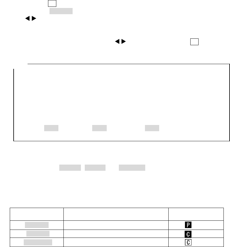
- 26 -
2.4 CF Control screen
While scanning is in off status and the 12 CF key is pressed, the screen switches to the CF
control screen and CF memory control can be performed. To return to the scan screen, press the
12 CF key once more. See Sections 3.6.2 to 3.7.4 for how to control the CF memory. The CF
control screen is shown in Figure 2-9.
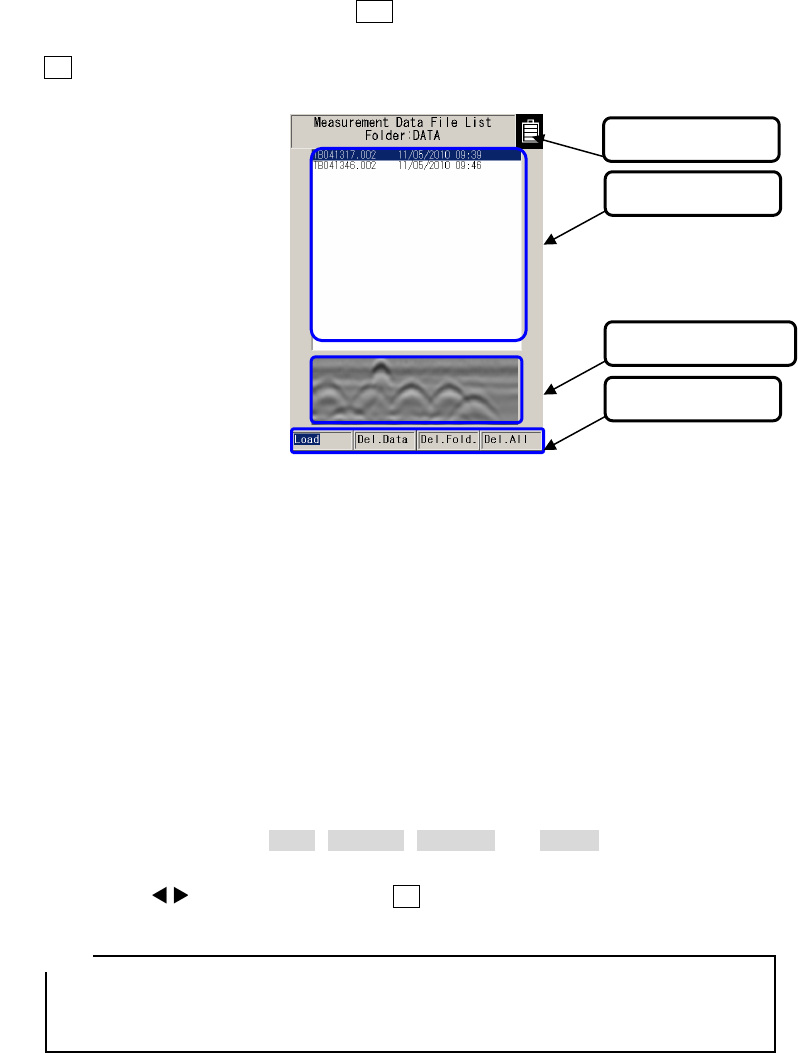
Figure 2-9 CF Control Screen
(1) Title
Displays the folder name accessed on the CF memory. To change the accessed folder, see
Section 2.3.9 Folder.
(2) File selection
Displays the file names for data saved on the CF memory. To select a file, move the cursor
(inverse video line) on the desired file by pressing the ▲▼ cursor keys.
(3) Thumbnail image display
Displays the scan result stored in the file selected in (1) as a thumbnail.
(4) Control functions
Displays control functions ( Load , Del.Data , Del.Fold. , and Del.All ) for the CF memory. To
select and execute a function, move the cursor (inverse video line) on the desired function by
pressing the cursor keys and press the 5 ENTER key.
• The thumbnail displays a part of the selected file (Distance direction; around 0.5 m,
depth direction: around half of the display range). The image processing selected at
the image processing setting is applied to the thumbnail image.
(2) File selection
(3) Thumbnails
(4) Control items
Remarks
(1) Title