Japan Radio NJJ-200 Handy Search User Manual NJJ 95A
Japan Radio Co Ltd. Handy Search NJJ 95A
Contents
- 1. Users Manual 1
- 2. Users Manual 2
- 3. Users Manual 3
- 4. Instruction of testing sample
Users Manual 1

NJJ-200
Handy Search
Users Guide
(For FCC and CE Version)
i
I. Preface
Thank you very much for purchasing JRC NJJ-200 Handy Search.
This product nondestructively locates, detects, and displays the depths and
positions of rebars in reinforced concrete structures.
●Before starting to use this product read this manual carefully to ensure correct and
trouble-free operations.
●Keep this manual handy for reference. Refer to the manual when facing
uncertainties or when experiencing troubles during operation.
DC20-NJJ-200
Firust Edition Nov 2013
ii
II. Before Operation
Pictorial Indication
Various icons are indicated in this manual and are labeled on this product
to ensure your safe and correct operations and to prevent any danger to
you and/or other persons and any damage to your property during
operation. Such indications and their meanings are as follows. Please
understand them before reading this manual.
Examples of Pictorial Indication
y JRC assumes no liability for any damage (such as damage caused to
rebars, electrical pipes, gas pipes, etc.) arising from scan results using
this product.
y JRC assumes no liability for any damage arising from the
disappearance of scan results stored in memory cards.
y Make sure to select and use Smartphone which is confirmed that it can
be connected to the sensor unit by referring to Smartphone’s manual.
For the requirements to Smartphone, refer to Section 13.4 Smartphone.
JRC assumes no liability for any damage (such as damage caused to
Smartphone and the senor unit, etc.) arising from the incorrect
operation different from the operation described in this manual.
WARNING
This indication is shown when danger of being
killed or seriously injured is possible if this
indication is neglected and this product is not
operated correctly.
CAUTION This indication is shown when injury or property
damage is possible if this indication is neglected
and this product is not operated correctly.
Electric
shock
A △ mark indicates CAUTION (including
DANGER and WARNING). Detailed content of
the specific CAUTION (“Electric Shock” in the
example on the left.) is shown in the mark.
Disassembling
Prohibited
Prohibition
A mark indicates prohibition. Detailed content
of the prohibited action (“Disassembling
Prohibited” in the example on the left.) is shown
in the mark.
Disconnect the
power plug
Instruction
A ●mark indicates instruction. Detailed content
of the instruction (“Disconnect the power plug” in
the example on the left.) is shown in the mark.
iii
III. Precautions for Use
WARNING
Do not use any battery pack other than the recommended battery
packs. Doing so may cause fire, electric shock, or breakdown.
Do not short-circuit the terminals of the battery charger or battery
pack. Doing so may cause fire, explosion, or breakdown.
Do not insert metallic or flammable objects into the CF memory slot.
Doing so may cause injury, fire, electric shock, or breakdown.
Do not disassemble, modify, heat, or place battery pack in fire.
Doing so may cause fire, explosion, or breakdown.
Do not use any charger other than the recommended battery
charger to charge the battery pack. Doing so may cause fire,
electric shock, or breakdown.
Do not disassemble, modify, or repair this product by yourself.
Doing so may cause fire, electric shock, or breakdown.
If the power cord is damaged (exposure of the core wire, open
circuit failure, or break in the sheath), contact our nearest branch
office (See Section 14), sales outlet, or service station for a
replacement power cord. Use of a damaged power cord may cause
fire or electric shock.
Do not connect/disconnect the power plug by wet hands. Doing so
could cause an electric shock.
Do not use (place) this product in a location where it is exposed to
flammable or corrosive gas. Doing so could cause fire, personal
injury, or breakdown.
This product has a waterproof construction but must not be dipped
in water. Do not expose this product to water or moisture, and do
not use it in rainy weather. Doing so could cause an electric shock
or breakdown.
Stop using this product immediately when a sign of malfunctioning
is detected, and follow only the instruction described in Section 9.3
Troubleshooting. If it cannot be restored to normal operation,
contact our nearest branch office (See Section 14), sales outlet,
or service station. Use of this product in an abnormal state could
cause fire or breakdown.
Should this product emit an abnormal sound, odor, or smoke,
immediately turn off the power switch, remove the battery pack,
disconnect the power plug from the socket outlet, and contact our
nearest branch office (See Section 14), sales outlet, or service
station. Use of this product in an abnormal state could cause fire,
electric shock, or breakdown.
iv
CAUTION
Before disposing of the used lithium ion battery, insulate the
charging terminals by taping or the like. Otherwise, the battery
could cause fire or explosion if short-circuited.
Judge the scan result with considering the depth sensing
capability of this product. Since the depth scan capability of this
product is subject to the conditions of the object of investigation,
judging the scan result with no consideration of the depth scan
capability may cause the cutting of rebars.
Put your hand through the hand strap and hold this product.
Dropping of this product may cause an accident such as a device
breakdown or personal injury.
When disconnecting the power cord, hold the plug. Pulling the
power cord by itself may cause cord damage, fire, or electric
shock.
Do not place this product on an unstable place such as a wobbly
table or sloping surface. Doing so may cause a personal injury or
breakdown when it drops or falls.
Do not use (place) this product in a humid or dusty location, or a
location where water, oil, or chemical may splash onto this
product. Doing so may cause fire, electric shock, or breakdown.
Do not use (place) this product in a location where it is subject to
vibration or shock. Doing so may cause a personal injury or
breakdown.
When loading/unloading printing paper, be careful not to cut or
jam your fingers in the printer. Otherwise a personal injury,
accident, or breakdown may be caused.
Point the antenna surface in the direction of the object (concrete)
while you are performing a probe. If it is pointed into the air or
otherwise unsuitable direction, it can cause malfunction of other
equipment or other such accidents.
Do not use this product near a radio or TV set. Doing so may
cause noise or poor reception such as disturbance of television
pictures. Doing so also adversely affects the depth sensing
capability of this product, and may cause the cutting of rebars.
Do not use this product near a transceiver that transmits
electromagnetic waves. Electromagnetic waves from the
transceiver may adversely affect the depth sensing capability of
this product, and may cause the cutting of rebars.
When this product is used for probing on a road, take safety
precautions such as providing guard fences to prevent traffic
accidents.

v
CAUTION
IMPORTANT NOTE: To comply with FCC & IC RF exposure
compliance requirements, the antenna used for this transmitter
must be installed to provide a separation distance of at least 20
cm from all persons and must not be co-located or operating in
conjunction with any other antenna or transmitter.
vi
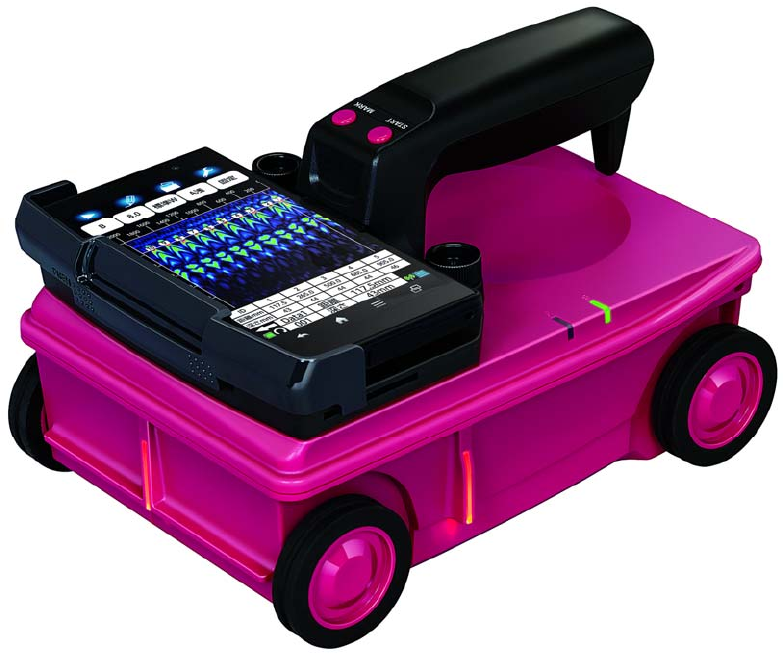
IV. Appearance

vii
V. Glossary of Terms
A-mode
Displays received waveform as it is. The conditions of
concrete directly underneath this product are displayed
as reflected waveform in real time.
B-mode
Displays the vertical cross section of a scan point by
gradating the reflected waveform shown in A-mode
according to reflection intensity and continuously
displaying it.
BA-mode Displays both B-mode and A-mode images at the same
time.
Real time
auto surface
wave
processing
Image processing to automatically remove the unwanted
waves reflected from the concrete surface during
scanning by using the internal fixed surface wave data
and shows only the reflected wave from rebars etc.
Real time
manual
deduction
processing
Image processing used in the case where the unwanted
waves reflected from the concrete surface can not be
fully removed by using the real time auto surface wave
processing and the unwanted waves remain as the form
of stripes in the scan result.
In this Image processing, an arbitrary line is designated
while scanning. The data of the designated line is
subtracted from the scan result data, and the reflected
wave from the concrete surface is automatically removed.
Thus, only the reflected waves from rebars etc. are
shown.
Real time
auto user
surface wave
processing
Image processing to automatically remove the unwanted
waves reflected from the concrete surface during
scanning by using the surface wave data which are
defined by the user and stored in the product and shows
only the reflected wave from rebars etc.
Fixed surface
wave
processing
Image processing to remove the unwanted waves
reflected from the concrete surface by using the internal
fixed surface wave data and shows only the reflected
wave from rebars etc.
User surface
wave
processing
Image processing to remove the unwanted waves
reflected from the concrete surface by using the surface
wave data which are defined by, used, and stored in the
product. This image processing shows only the reflected
wave from rebars etc.

viii
Glossary of Terms (continued)
Deduction
processing
Image processing to remove the stripe reflected waves
throughout the entire depth, such as reflected waves from
the concrete surface and from the rear surface etc. In this
processing, an arbitrary line in the scan result is
designated and the designated line is subtracted from the
scan result data. Only the reflected waves from rebars
etc. are shown.
Manual
surface wave
processing
Image processing to remove the unwanted waves
reflected from the concrete surface by using the surface
wave data of the designated position in the search results
and shows only the reflected waves from rebars etc. In
this processing, an arbitrary line is designated from scan
results. The surface portion of the designated line is
subtracted from the scan result data, and the reflected
waves from the concrete surface are removed.
Average wave
processing
Image processing to remove the stripe reflected waves
throughout the entire depth, such as reflected waves from
the concrete surface and from the rear surface etc. In this
processing, the averaged waveform of the entire scan
results data are calculated and is subtracted from the
scan result data, Only the reflected waves from rebars
etc. are shown.
Peak
processing
Image processing that shows only the waveform of the
first peak on the +side of the scan result. This enables
removal of multiple reflected signals and only displays
the upper rebars.
Original image Restores the image processed result to the original state
and displays unprocessed raw data.
Distance feed
scan
Scan method that performs scanning in accordance with
Handy Search's traveling distance, using the distance
detector mounted on the wheels of this product.
Time feed
scan
Scan method that performs B-mode scanning at preset
time intervals, regardless of movement of this product.
Relative
dielectric
constant
Object-specific coefficient. The radio wave propagation
velocity changes with the relative permittivity (dielectric
constant). Therefore, the wave propagation velocity and
search depth change based on the relative permittivity of
the concrete. Calculation error of search depth can be
reduced by setting a depth calibration value.
ix
Contents
I. Preface ........................................................................................ i
II. Before Operation ..................................................................... ii
III. Precautions for Use .............................................................. iii
IV. Appearance ............................................................................ vi
V. Glossary of Terms .................................................................. vii
1. Product overview ..................................................................... 1
1.1. FUNCTIONS AND PERFORMANCES ......................................................................... 2
1.2. FEATURES ............................................................................................................... 3
1.3. CONFIGURATION .................................................................................................... 5
1.4. OVERALL SYSTEM DIAGRAM .................................................................................. 6
1.5. NAME AND FUNCTION OF EACH PART ................................................................... 7
2. Preparation before starting to use ....................................... 10
2.1. OVERVIEW OF PREPARATION .............................................................................. 10
2.2. NJJ-200 APPLICATION INSTALLATION ................................................................ 11
2.3. SMARTPHONE LANGUAGE SETUP ....................................................................... 17
2.4. ATTACHMENT AND DETACHMENT OF THE HANDLE ........................................... 17
2.5. ATTACHMENT OF THE HANDSTRAP .................................................................... 18
2.6. ATTACHMENT OF THE BATTERY PACK ................................................................ 19
2.7. DETACHMENT OF THE BATTERY PACK ................................................................ 20
2.8. COMMUNICATION SETUP .................................................................................... 21
2.9. ATTACHMENT AND DETACHMENT OF SMARTPHONE ......................................... 24
3. Basic scan procedure ............................................................. 25
3.1. PREPARATION FOR SCANNING LINES ................................................................. 27
3.2. BATTERY CAPACITY CHECK ................................................................................. 28
3.3. SCANNING ........................................................................................................... 30
3.4. INTERPRETING THE SCAN RESULTS ................................................................... 33
3.5. POWER OFF .......................................................................................................... 34
3.6. SHUTDOWN AND STORAGE ................................................................................. 34
4. NJJ-200 application functions .............................................. 35
4.1. MAIN SCREEN ...................................................................................................... 35
4.2. CURSOR AND SCROLL .......................................................................................... 38
x
4.3. [MARK] ICON ....................................................................................................... 39
4.3.1. MARKER ADDITION .......................................................................................... 39
4.3.2. MARKER DELETION ......................................................................................... 40
4.3.3. MARKER LIST ................................................................................................... 41
4.4. [FILE/PRINT] ICON .............................................................................................. 43
4.5. [PARAMETER] ICON ............................................................................................. 44
4.5.1. [COLOR] MENU ................................................................................................. 44
4.5.2. [UNIT] MENU .................................................................................................... 46
4.6. [DISPLAY MODE] ICON ......................................................................................... 48
4.7. [RELATIVE PERMITTIVITY] ICON ......................................................................... 49
4.7.1. RELATIVE PERMITTIVITY AND DEPTH CALIBRATION ...................................... 50
4.8. [VIEW RANGE] ICON ............................................................................................ 51
4.9. [SENSITIVITY] ICON ............................................................................................. 52
4.9.1. SENSITIVITY ..................................................................................................... 53
4.10. [IMAGE PROCESSING] ICON ................................................................................. 54
4.10.1. IMAGE PROCESSING ....................................................................................... 55
4.10.2. FIXED SURFACE PROCESSING ....................................................................... 56
4.10.3. USER SURFACE PROCESSING ......................................................................... 56
4.10.4. SUBTRACTION ................................................................................................ 59
4.10.5. MANUAL SURFACE PROCESSING ................................................................... 61
4.10.6. AVERAGING .................................................................................................... 63
4.10.7. PEAK PROCESSING ......................................................................................... 64
4.10.8. ORIGINAL IMAGE ........................................................................................... 65
4.11. PARAMETER SETUP SCREEN ............................................................................... 66
4.11.1. DEVICE SETTING: [RELATIVE PERMITTIVITY] MENU .................................... 67
4.11.2. DEVICE SETTING: [SENSITIVITY] MENU ........................................................ 68
4.11.3. DEVICE SETTING: [VIEW RANGE] MENU ....................................................... 69
4.11.4. DEVICE SETTING: [IMAGE PROCESSING] MENU ........................................... 70
4.11.5. DEVICE SETTING: [COLOR] MENU ................................................................. 71
4.11.6. DEVICE SETTING: [DEVICE ORIENTATION SETTING] MENU ......................... 73
4.11.7. DEVICE SETTING: [UNIT] MENU .................................................................... 74
4.11.8. DEVICE SETTING: [LOCATION NOTIFICATION] MENU ................................... 75
4.11.9. DEVICE SETTING: [SOUND] MENU ................................................................ 75
4.11.10. PREFERRED SETTING: [RELATIVE PERMITTIVITY] MENU .......................... 76
4.11.11. PREFERRED SETTING: [SENSITIVITY] MENU .............................................. 76
4.11.12. PREFERRED SETTING: [RANGE] MENU ....................................................... 77
4.11.13. PREFERRED SETTING: [COLOR] MENU ....................................................... 77
4.11.14. PREFERRED SETTING: [UNIT] MENU .......................................................... 78
4.11.15. SENSOR SETTING: [MEASUREMENT MODE] MENU .................................... 79
4.11.16. SENSOR SETTING: [LED] MENU .................................................................. 80
4.11.17. SENSOR SETTING: [DISTANCE CORRECTION] MENU .................................. 80
4.11.18. SENSOR SETTING: [CHANNEL] MENU ......................................................... 81
4.11.19. OTHER: [SENSOR SELECT] MENU ............................................................... 82
4.11.20. OTHER: [VERSION] MENU ........................................................................... 83
4.11.21. OTHER: [INITIAL SETTING] MENU ............................................................... 84
4.12. FILE OPERATION SCREEN ................................................................................... 85
xi
4.12.1. [OPEN] MENU ................................................................................................. 86
4.12.2. [SAVE/PRINT] MENU ....................................................................................... 87
4.12.3. [SELECT FOLDER] MENU ............................................................................... 88
4.12.4. [DATA NUMBER SETTING] MENU ................................................................... 89
4.13. MARKER OPERATION ........................................................................................... 90
4.13.1. [HIDE MARKERS] MENU ................................................................................ 90
4.13.2. [SHOW MARKER LIST] MENU ......................................................................... 91
4.13.3. [MARKER DETAILS] MENU ............................................................................. 92
4.13.4. [SORT MARKER] MENU .................................................................................. 94
4.13.5. [AUTOMARK] MENU ...................................................................................... 94
4.13.6. [MARKER GROUP SETTING] MENU ................................................................ 95
5. External output ..................................................................... 96
5.1. SAVE THE SCAN RESULT INTO THE FILE ............................................................. 96
5.1.1. BINARY FORMAT ............................................................................................... 96
5.1.2. TEXT FORMAT ................................................................................................... 99
5.2. SAVING THE SCAN DATA .................................................................................... 100
5.3. DATA FILE OPERATION ...................................................................................... 102
5.4. DISPLAYING THUMBNAIL IMAGE OF THE DATA FILE ........................................ 103
5.5. READING THE SCAN DATA FROM THE DATA FILE .............................................. 104
5.6. DELETING THE DATA FILE ................................................................................. 105
5.7. DELETE ALL FILES UNDER THE FOLDER .......................................................... 106
5.8. PRINTER OUTPUT .............................................................................................. 107
5.8.1. PREPARATION FOR THE PRINTER .................................................................. 107
5.8.2. BLUETOOTH PAIRING ...................................................................................... 114
5.8.3. PRINTING SCAN DATA ..................................................................................... 117
6. Application ........................................................................... 120
6.1. RELATIVE PERMITTIVITY SETUP ....................................................................... 120
6.2. PROCEDURE TO MARK THE REBAR ................................................................... 125
6.2.1. FORWARD SCAN MARKING ............................................................................. 125
6.2.2. BACKWARD SCAN MARKING .......................................................................... 126
6.3. AUTOMARK FUNCTION ..................................................................................... 127
6.4. LOCATION NOTIFICATION FUNCTION ............................................................... 133
6.5. SCREEN ROTATION ............................................................................................ 137
6.6. SORT MARKER ................................................................................................... 138
6.7. COMMUNICATION CHANNEL SETUP ................................................................. 141
6.8. DISTANCE ERROR CORRECTION ........................................................................ 142
6.9. SOFTWARE VERSION UP .................................................................................... 143
6.9.1. SMARTPHONE APPLICATION VERSION UP ..................................................... 143
6.9.2. SOFTWARE VERSION UP FOR SENSOR UNIT .................................................. 149
7. Battery pack and battery charger ...................................... 153
7.1. BATTERY PACK HST30002 ............................................................................... 154
7.2. BATTERY CHARGER PPT20003 ........................................................................ 155
xii
8. Theory ................................................................................... 156
8.1. APPLICABLE CONDITION ................................................................................... 157
9. Maintenance and inspection ............................................... 158
9.1. DAILY INSPECTION ............................................................................................ 158
9.2. DAILY MAINTENANCE ....................................................................................... 158
9.3. TROUBLESHOOTING .......................................................................................... 159
10. After sales service .............................................................. 161
11. Disposal .............................................................................. 162
11.1. DISPOSAL OF THE USED BATTERY PACK ........................................................... 162
11.2. DISPOSAL OF THIS PRODUCT ............................................................................ 162
12. Regulation Note ................................................................. 163
12.1. FCC/IC CAUTION .............................................................................................. 163
12.2. FCC NOTICE (FOR U.S. CUSTOMERS): ............................................................. 164
13. Specifications ..................................................................... 166
13.1. HANDY SEARCH NJJ-200 ................................................................................. 166
13.2. BATTERY PACK HST30002 ............................................................................... 168
13.3. BATTERY CHARGER PPT20003 ...................................................................... 168
13.4. SMARTPHONE .................................................................................................... 168
14. Where to contact ................................................................ 169

1
1. Product overview
To extend the life of concrete buildings, continuing the inspection and implementing
renovation and repair appropriately of the buildings is essential. At the same time, the
accurate and quick method for the building inspection is required to promote the building
maintenance. This product is indispensable for repairing/rebuilding and maintaining
reinforced concrete structures using its accurate and speedy diagnostic technology.
This product (concrete internal probe device) radiates electromagnetic waves through the
surface of concrete and receives reflected signals from objects inside the concrete such as
rebars, cavities, or other objects that have different electrical characteristics from concrete.
Object position and depth are then displayed and recorded as image data.
Judge the scan result in consideration of the depth sensing capability of this
product. Since the depth sensing capability of this product is subject to the
conditions of the object of investigation, judging the scan result with no
consideration of the depth sensing capability may cause the accidental cutting
of rebars.
IMPORTANT NOTE: To comply with FCC & IC RF exposure compliance
requirements, the antenna used for this transmitter must be installed to provide
a separation distance of at least 20 cm from all persons and must not be
co-located or operating in conjunction with any other antenna or transmitter.
CAUTION

2
1.1. Functions and performances
Table 1-1 shows functions and performances of this product..
Table 1-1 Functions and performances (1/2)
No. Item Functions and Performances
1 Search method Electromagnetic wave radar method
2 Search object Rebar, Polyvinyl-chloride pipe, Cavity, etc.
3 Search depth 5 to 300 mm for concrete having a relative dielectric
constant 6.2 and the top rebar of the diameter ≧ 6 mm
4 Depth resolution
Approx. 1 mm at the view range setting of Shallow
Approx. 2 mm at the view range setting of Deep
5
Horizontal
discrimination
resolution
≧ 75 mm for the scanned object located at depth < 75 mm
≧ Depth of the scanned object located at depth ≧ 75 mm
※Typical performance for the reference concrete provides
discrimination between two rebars of the interval 15 mm at
depth 75 mm and of the interval 40 mm at depth 175 mm.
6 Horizontal
distance resolution 2.5 mm
7 Maximum scan
distance
No limit (The scan data shown on Smartphone screen and
saved into the file is maximum 15 m of the latest scan data
from the scan stop point.)
8 Display mode B-mode (Vertical Cross Section) and BA-mode(Vertical
Cross Section and Reflection Waveform Graph)
9
Image
proces
sing
When
scanning
Real time auto surface wave processing, Real time manual
deduction processing, Real time user surface wave
processing
At idle
state
Fixed surface wave processing, User surface wave
processing, Deduction processing, Manual surface wave
processing, Average wave processing, Peak processing,
Original image
10 Depth calibration 2.0 to 20.0 ( 0.1 step) and time
11 Maximum scan
speed
Approx. 40 cm/s, Over speed alarm capability
12 Control functions
Marker functions, Battery capacity indicator, Screen
rotation, AutoMark function, Location notification function,
File operations, Image data processing, Display functions
(color, etc)
13 Data output
functions
Data saving into the memory inside Smartphone
(Approx. 100 scan data (15 m scan data of binary format)
can be saved into the memory of 1 GB capacity)
Print out to the optional printer: Monochrome printer
14 Scan dead space ≦80 mm
3
1.2. Features
This product has the following features. This product can:
(1) Detect either metallic or non-metallic object.
Reflected electromagnetic waves are generated at an interface when the electrical
property of an object is different from that of concrete. Thus, this product can probe
polyvinyl-chloride pipes and cavities (dependent on the position and size) as well as the
rebar. Note that polyvinyl-chloride pipes and cavities echo weakly in compared with the
rebar. If a polyvinyl-chloride pipe or cavity is near or below the rebar, the reflected signals
from the polyvinyl-chloride pipe or cavity may not be obtained due to the strong reflected
signals from the rebar. Thus, care should be taken when you make a judgment on the
scan result.
(2) Detect rebars that cross the scanning direction.
Rebars that cross the scanning direction make a large magnetic wave reflection. On the
other hand, the rebar that is parallel to the scanning direction makes a smaller magnetic
wave reflection. Even if scanning is performed above rebars that is parallel to the scanning
direction, this product can still detect any rebars that are crosswise to the scanning
direction.
(3) Obtain continuous scan results.
The scan result are obtained as a representation of the vertical cross section (continuous
scan result) of the inside of concrete. Thus, a comprehensive view of the internal concrete
conditions can be obtained.
(4) Obtain scan results at the site.
This product does not need to be secured to the surface of concrete. Scanning is carried
out while this product is moved, and scan results concerning the internal conditions of the
concrete can be provided immediately.
(5) Save and recall scan data.
The scan data can be saved and recalled to/from an internal memory of Smartphone
(controller). The data saved in Smartphone can also be sent to an external PC by using
PC connection function of Smartphone.
(6) Print the scan data without cable connection.
The scan data can be printed out to the optional printer via the Bluetooth interface of
Smartphone as the controller.
4
(7) Perform real time automatic surface wave processing
Internal fixed surface wave data is used to automatically remove the wave reflected from
the concrete surface during scanning enabling the showing of the reflected wave from
rebars. Furthermore, surface wave processing can be switched to processing that uses
scan data surface waves during scanning (real time manual deduction) enabling highly
accurate surface processing.
(8) Change sensitivity and perform image processing for scan data after
completing the scan.
This product can display scan results after changing sensitivity or performing image
processing (manual surface wave processing, peak processing, original image, fixed
surface wave processing, or deduction processing). Thus, performing a scanning again
with a new sensitivity setting is not necessary.
(9) Display the data of an arbitrary point after scanning (scroll function).
This product can store the data of 15 m width at a time and display the data of arbitrary
points continuously.
(10) Compact and light weight.
This product weighs only about 1.0 kg(not including the controller: Smartphone), and it has
easy operations.
(11) Operate with the battery pack.
This product (sensor unit not including the controller) can operate with the battery pack for
about 7 hours (at normal temperature).

5
1.3. Configuration
(1) Standard configuration
Table 1-2 shows the standard configuration of this product.
Table 1-2 Standard Configuration
Name Model Numbe
r
Q
t
y
Remarks
Handy search NJJ-200 1 Sensor unit and handle
Battery pack HST3002 1 For sensor unit
Battery charger PPT20003 1
AC cable 28AD0-J 1 For battery charger
Hand strap MPXP35073 1
Storage box MPBX48072 1
Controller application software H-7YRBD0007 1 CD-R
Interface cable between
Smartphone and a PC - 1 USB cable
Users manual DC00-NJJ-200 1 This manual
Quick operation guide DC10-NJJ-200 1
Test results -
(2) Option
Table 1-3 shows optional accessories that are available in addition to the standard
components.
Table 1-3 Options
Name Model Number Remarks
Controller - Smartphone
Battery pack HST30002 For the sensor unit
Battery charger PPT20003 For the battery pack used in the
sensor unit
Printer PD-24BT
Including an operation manual, a
battery pack, an AC adapter, and a
printing paper (1 ea)
Printing paper RP11250T One box including 10 paper rolls
Battery pack for the printer PD69910
AC adapter for the printer PD79936-00F
AC cable for the printer PD79914-0S
Charger for the printer PD69922
Extension bar MPBC38332
Calibration certification -
Traceability certification -
6
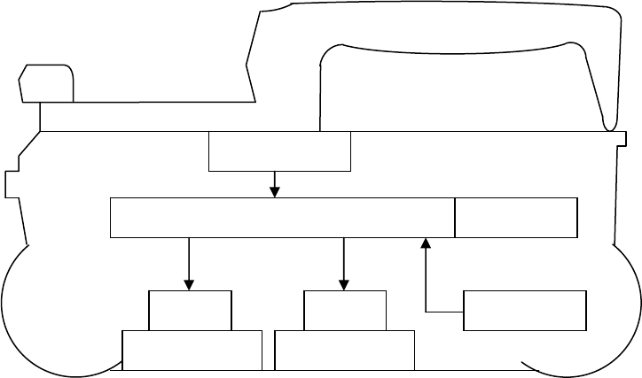
1.4. Overall system diagram
Figure 1-1 shows the overall system diagram of this product.
Figure 1-1 System Diagram
Control section
Trans antenna Receive antenna
Distance
Detecto
r
Operation switch
Trans Receive
WLAN unit
7
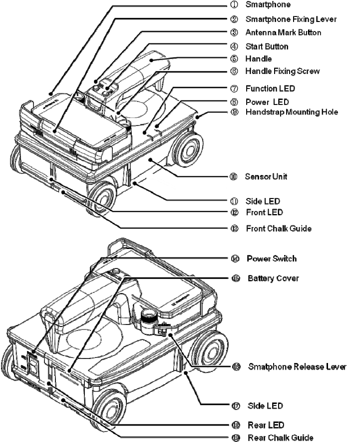
1.5. Name and function of each part
This section shows the name and function of each part of NJJ-200 sensor unit and handle.
Figure 1-2 Name and function of each part

8
Table 1-4 Name and function of each part (1/2)
Ref Name Function
① Smartphone Controls the sensor unit (⑩) and displays the scan data
obtained by the sensor unit on its screen.
② Smartphone
fixing lever Used to fix Smartphone (①) to the handle (⑤). For more
details, refer to Section 2.9 Attachment and detachment of
Smartphone.
③ Antenna mark
button Used to enter antenna marks during the scan.
④ Start button Used to start and stop the scan.
⑤ Handle Used to fix Smartphone (①) to the sensor unit (⑩) and to
move the sensor unit (⑩). It is removable. For more details,
refer to Section 2.4 Attachment and detachment of the
handle.
⑥ Handle fixing
screw Used to fix the handle (⑤) to the sensor unit (⑩). For more
details, refer to Section 2.4 Attachment and detachment of the
handle.
⑦ Function LED Multi-functional LED. It shows the battery capacity at the
power on. For more details, refer to Section 3.2
Section Battery capacity check.
⑧ Power LED Indicates the power state (on/off) of the sensor unit (⑩) .
⑨ Handstrap
mouting hole Used to mount the handstrap. For more details, refer to
Section 2.5 Attachment of the handstrap.
⑩ Sensor unit Sensor unit of this product. It is controlled by Smartphone. In
scanning, it transmits the electromagnetic wave, receives the
wave reflected from the embedded object, then sends
detected data to Smartphone..
⑪
⑰
Side LED Indicates the position of the sensor unit being superposing on
the specific location (the position of a marker or an antenna
mark). Also it is used to align the position (center of the built-in
antenna) of the sensor unit with the start line (orthogonal for
the scan line).
⑫
⑱
Front LED
Rear LED Indicates the position of the sensor unit being superposing on
the specific location (the position of a marker or an antenna
mark). Also it is used to align the position (center of the built-in
antenna) of the sensor unit with the scan line.
⑭ P
o
wer switch Power switch of the sensor unit.

9
Table 1-4 Name and functions of each part (2/2)
Ref Name Function
⑮ Battery cove
r
Battery cover of the sensor unit. For more details, refer to
Sections 2.6 Attachment of the battery pack
and 2.7 Detachment of the battery pack.
⑯ Smartphone
release lever Lever used to remove Smartphone from the handle (⑤). It
can release Smartphone fixing lever (②). For more details,
refer to Section 2.9 Attachment and detachment of
Smartphone.
⑲ Rear chalk
guide Chalk guide used to mark the rebar position when scanning
forward. For more details, refer to Section 6.2 Procedure to
mark the rebar.
⑬ Front chalk
guide Chalk guide used to mark the rebar position when scanning
backward. For more details, refer to Section 6.2 Procedure to
mark the rebar.
10
2. Preparation before starting to use
This section decribes the preparation before starting to use this product.
This product uses a Smartphone as the control display, so that it requires the preparation
of the Smartphone before starting to use. As the preparation related with Smartphone, you
need to install the control software NJJ-200 application into Smartphone and to complete
the communication setup between Smartphone and the sensor unit.
NJJ-200 application installation is executed by copying NJJ-200 application file from PC to
Smartphone and installing NJJ-200 application as an external application software into
Smartphone. The procedure depends on Smartphone model. This section describes the
general procedure most common for Smartphone. If the procedure provided in this section
is not matched with Smartphone used, install NJJ-200 application into Smartphone by
referring to the manual of the Smartphone used.
2.1. Overview of preparation
The preparation consists of the following steps.
(1) Install NJJ-200 application into Smartphone. For the detailed procedure, refer to
Section 2.2 NJJ-200 application installation.
(2) Set the language for the Smartphone. For the detailed procedure, refer to
Section 2.3 Smartphone language setup.
(3) Attach the handle to the sensor unit. For the detailed procedure, refer to
Section 2.4 Attachment and detachment of the handle.
(4) Attach the handstrap to the sensor unit. For the detailed procedure, refer to
Section 2.5 Attachment of the handstrap.
(5) Attach the battery pack to the sensor unit. For the detailed procedure, refer to
Section 2.6 Attachment of the battery pack.
(6) Set the communication setup between Smartphone and the sensor unit. For the
detailed procedure, refer to Section 2.8 Communication setup.
(7) Attach Smartphone to the sensor unit. For the detailed procedure, refer to
Section 2.9 Attachment and detachment of Smartphone.
11
2.2. NJJ-200 application installation
Install NJJ-200 application into Smartphone with the following procedure.
(1) Copy NJJ-200 application file from PC to Smartphone with the following procedure.
NJJ-200 application file is provided in the CD-R attached to this product.
By connecting Smartphone and a PC by using a USB cable (or a micro USB cable),
Smartphone can be recognized and mounted as a removal data drive on the PC, then the
file copy operation of drag and drop become available. By using this capability, copy
NJJ-200 application from the PC to Smartphone.
a) On Smartphone, enable the file operation on Smartphone’s memory card from the
PC by setting Smartphone into Card reader mode or File transfer mode (MSC). For
the detailed procedure, refer to the manual attached to Smartphone.
Example: Tap [Setting], [Device setting], [External Connection], [USB
Connection], then [Card reader mode].
b) Connect Smartphone to a USB port of the PC by using a micro USB cable.
c) On Smartphone, tap [Turn on USB Storage].
d) On the PC, Confirm that Smartphone’s data storage is recognized and mounted as a
removal data drive on the PC.
e) Create the folder “NJJ200” in Smartphone data drive mounted in steps above.
f) Insert the furnished CD-R into the CD-R Drive of the PC.
g) Copy NJJ-200 application file (File name: “NJJ-200.apk”) on the CD-R to the folder
“NJJ200” on Smartphone by using the drag and drop capability.
h) Remove the drive of Smartphone from the PC by using the PC function of the safety
hardware removal.
i) On Smartphone, tap [Turn off USB storage].
12
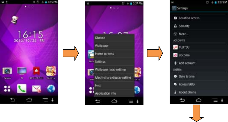
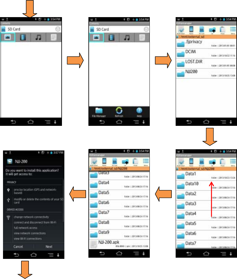
(2) Install NJJ-200 application into Smartphone with the following procedure.
a) At the security setting in Smartphone, set the setting so as to allow the installation of
applications from the unknown sources. For the detailed procedure, refer to the
manual attached to Smartphone.
Example: Tap [Setting], [Device setting], [Lock & Security], and tap [Unknown
source].
b) Activate the file management application (Contents manager, File commander,
etc.) in Smartphone. Then install NJJ-200 application by tapping [NJJ-200] which
was copied into the memory card of Smartphone.
Make sure [NJJ-200] icon is registered in [Downloaded] at [Application] screen on
Smartphone. If the icon is not registered, check if steps (1) and (2) above have been done
correctly. Figure 2-1shows an example of NJJ-200 application installation procedure.
To the next page
Figure 2-1 NJJ-200 application installation (1/4)
)
)
)
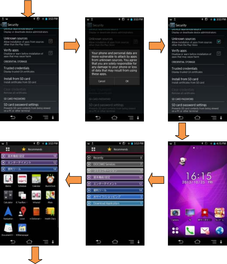
13
From the previous page
To the next page
Figure 2-1 NJJ-200 application installation (2/4)
)
)
)
)
)
)
14
From the previous page
To the next page
Figure 2-1 NJJ-200 application installation (3/4)
)
)
)
)
)
)
Press the button,
then release it.
Scroll
15
From the previous page
Figure 2-1 NJJ-200 application installation (4/4)
)
)
)
)
)
16
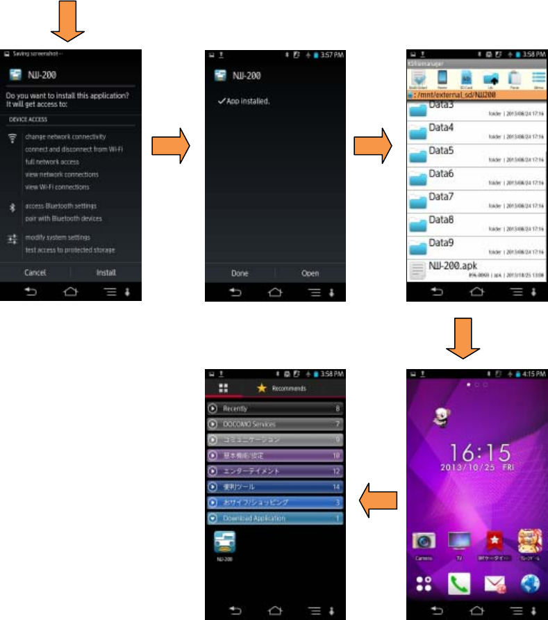
(1) NJJ-200 application operational verification
Make sure that NJJ-200 application is properly installed in Smartphone by the following
procedures (Refer to Figure 2-2). If it displays the main screen of NJJ-200 application, the
installation is completed successfully.
a) Turn on Smartphone. Wait a little, then the home screen of Smartphone appears.
b) Tap [Application] icon in the home screen of Smartphone.
c) Tap [NJJ-200] icon shown in [Download Application] to run NJJ-200 application.
Then an opening screen of NJJ-200 application appears as shown, then the main screen
of NJJ-200 application appears.
Figure 2-2 NJJ-200 application boot-up screen
)
)
17
2.3. Smartphone language setup
Switching the language of NJJ-200 application is made by the language setting in
Smartphone. Set the language of your choice to Smartphone by referring to the
Smartphone manual. NJJ-200 application supports Japanese and English. If other
languages are chosen, English is selected in NJJ-200 application..
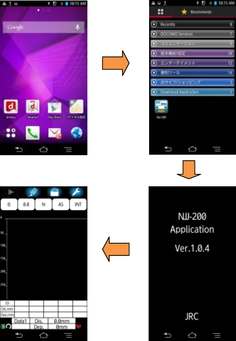
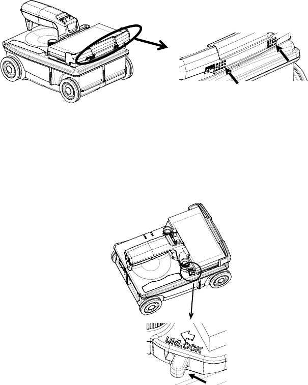
2.4. Attachment and detachment of the handle
The handle is attachable to and detachable from the sensor unit. The attachment and
detachment procedure are provided below.
(1) Detachment of the handle
Rotate the handle fixing screw counterclockwise. Remove the handle by pulling it toward
the rear and upward.
Figure 2-3 Detachment of the handle
(2) Attachment of the handle
Align and insert two hooks located at the front back plain of the handle into holes located at
the front top of the sensor unit. Then rotate the handle fixing screw clockwise and tighten
the screw.
Figure 2-4 Attachment of the handle
18
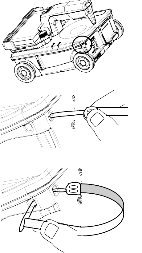
2.5. Attachment of the handstrap
A handstrap is furnished to the sensor unit as the standard accessory to prevent the
accidental dropping of the sensor unit. Attach the handstrap as shown in Figure 2-5 before
starting to use this product, and make sure to apply the handsrap to your wrist when
operating this product
Figure 2-5 Attachment of the handstrap
19
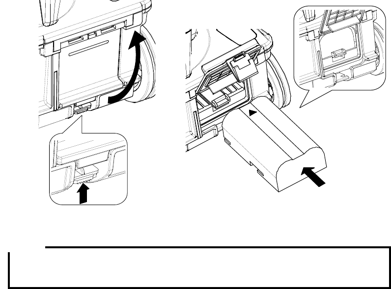
2.6. Attachment of the battery pack
This product supports only the battery pack as its power source. Attach the battery pack
into the sensor unit in accordance with the following steps.
(1) Make sure that the power switch (Figure 1-2 ⑭)is in OFF position.
(2) Open the battery cover by pushing up the locking tab located on the lower part of the
battery cover (Figure 1-2 ⑮).
(3) Insert the battery pack pin side first until it locks into place. (You should hear a “click”
when it locks into place.) Close the battery cover.
Figure 2-6 Attachment of the battery pack
y Always confirm that the power switch is turned to OFF position before installing or
removing the battery pack.
Note
20
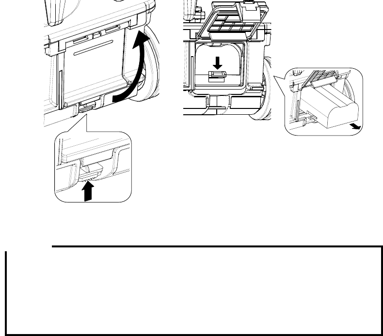
2.7. Detachment of the battery pack
When removing the battery pack, perform the following steps.
(1) Make sure that the power switch is in OFF position.
(2) Open the battery cover by pushing up the lock tab located on the lower part of the
battery cover.
(3) Press down the battery pack release button. Then the battery will be pushed out.
Remove the battery pack from the sensor unit. Be careful so as not to drop the
battery.
(4) Close the battery cover.
Figure 2-7 Detachment of the battery pack
y When safekeeping this product for a long term, make sure to detach the battery
pack from the sensor unit. If this product is left in the incorrect state for a long time
where the battery pack is not attached fully and the battery pack release button is
pushed down by the battery pack, the battery pack release button may be
damaged and become difficult to be locked due to its shape change.
Caution
21
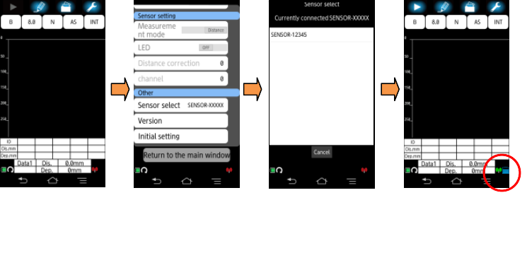
2.8. Communication setup
Use the following procedure to establish the communication between the sensor unit and
Smartphone through wireless LAN.
(1) Make sure the battery pack is installed and the sensor unit is switched to ON position.
(2) Turn on Smartphone. Home screen of Smartphone will appear after a while.
(3) Set Smartphone to Airplane mode.
(4) Tap [Application] icon on the home screen.
(5) Tap [NJJ-200] icon in [Downloaded application]. Then the opening screen of
NJJ-200 application appears and shows the main screen automatically.
(6) Long tap [Parameter] icon. Then the parameter setup screen appears.
(7) Tap [Sensor select] menu in the parameter setup screen. Then the sensor select
screen appears and lists sensor units available nearby Smartphone.
(8) Tap the ID of the used sensor unit in the sensor select screen.
(9) Return to the main screen. Then the communication between Smartphone and the
sensor unit is established, and the antenna icon turns from red to green and the color
of the sensor unit’s power LED changes from red to green.
Figure 2-8 Communication setup
Long tap the setting
icon, then the setting
screen appears.
Scroll the setting screen,
and tap the sensor
selection.
Tap the ID of the used
sensor unit in the shown
ID list.
Return to the main screen.
Then the color of the
antenna icon changes to
green.
)
)
)

22
Notes on wireless communication:
y Some devices operate using the same frequency bands adopted by this product.
Equipment such as microwave ovens and other home electronics, radios and
equipment used in various types of radio stations including Amateur Radio
stations, and devices that operate on industrial, scientific, or medical frequency
bands may experience interference from this product.
y In case any harmful radio interference occurred, immediately stop to use this
product. Then contact to one of our contact points described in Section 14 or the
distributor from which you purchased this product to get consultation about the
solution.
y
y Make sure that Smartphone is set to Airplane mode:ON. If NJJ-200 application
is started on Smartphone with Airplane mode:OFF, a message “Could not be set
to airplane mode.” appears. If such a messages appears, tap the [OK], then stop
NJJ-200 application. Set Smartphone to be in Airplane mode, then restart
NJJ-200 application.
y Use this product in the area of small electrical and magnetic noise. Otherwise ,
especially when using near a microwave oven, this product may be influenced by
magnetic or electrical noise, resulting noise level increased in the scan result or
unstable communication between the sensor unit and Smartphone.
y If used near TV or radio, harmful interference (including TV image distortion) may
occur.
y If the same channel is used by nearby wireless LAN access points, NJJ-200
application may not detect available sensor units correctly. In such case, change
the communication channel by referring to Section 6.7 Communication channel
setup.
Caution

23
y The digits following “SENSOR-“ in the sensor unit’s ID number displayed on the
sensor select screen corresponds with the last 5 digits in the serial number of the
sensor unit.
y Once Smart phone establishes the communication with the sensor unit, the ID of
the the sensor unit is registered as the present connection destination. From the
next boot up, NJJ-200 application establishes the communication with the
registered sensor unit automatically. When you want to connect with other sensor
unit, choose the desired ID of the sensor unit on a sensor select screen.
y The communication between Smartphone and the sensor unit is made at one by
one. When Smartphone has established the communication already with a sensor
unit, the other Smartphone cannot communicate with the sensor unit.
y When two or more sensor units are near Smartphone, the sensor select screen
displays all ID numbers of sensor units nearby Smartphone. Choose a ID number
including the serial number of the used sensor unit, then you can establish the
communication with the used sensor unit.
Note
24
2.9. Attachment and detachment of Smartphone
Smartphone is put on the handle and fixed by Smartphone fixing lever of the handle.
When attaching Smartphone on the handle, make sure first to release completely
Smartphone fixing lever, then place Smartphone on the handle. For the detachment
procedure of Smartphone, refer to the following (2) .
(1) Attachment Procedure
Place Smartphone at the front part of the handle. Then push and slide Smartphone fixing
lever located at the front end of the handle to lock Smartphone.
Figure 2-9 Attachment of Smartphone
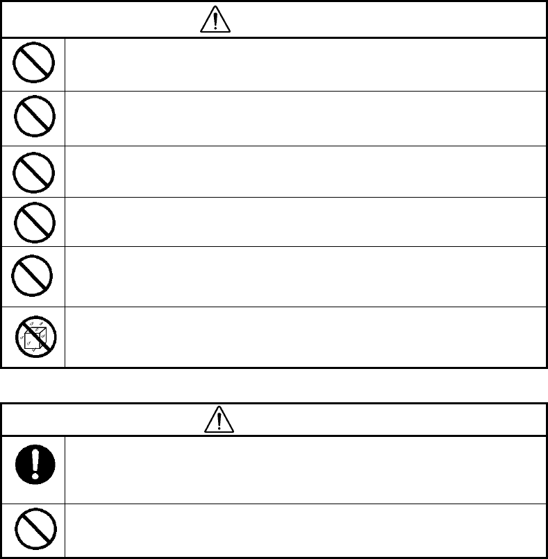
(2) Detachment
Push the lock lever located at the side of the handle toward the direction shown by the
label “Unlock”, then release Smartphone fixing lever completely. After confirming the lever
released completely, remove Smartphone from the handle.
Figure 2-10 Detachment of Smartphone
25
3. Basic scan procedure
This section describes the basic scan procedure. The following description assumes all the
preparations described in Section 2 have been completed successfully. If some
preparations have not been made yet, complete all the preparations in accordance with
Section 2. In the following description, each icon or button displayed in NJJ-200 application
is referred by using [its name].
WARNING
Do not use any battery pack other than the recommended battery packs.
Doing so could cause fire, electric shock, or breakdown.
Do not short-circuit the terminals of the battery charger or battery pack. Doing
so could cause fire, explosion, or breakdown.
Do not insert anything metallic or flammable into the battery pack slot. Doing
so could cause a personal injury, fire, electric shock, or breakdown.
Do not use any charger other than the dedicated battery charger to charge the
battery pack. Doing so could cause fire, electric shock, or breakdown.
Do not use (place) this product in a location where it is exposed to flammable
or corrosive gas. Doing so could cause fire, personal injury, or breakdown.
Handy Search has a waterproof construction but must not be placed in water.
Do not expose this product to water or moisture, and do not use it in rainy
weather. Doing so could cause an electric shock or breakdown.
CAUTION
Making a judgment on the scan results considers the depth scan capability of
this product. Since the depth scan capability of this product is subject to the
conditions of the object of investigation, judging the scan results with no
consideration of the depth scan capability may cause the cutting of rebars.
Put your hand through the hand strap and hold this product. Dropping of this
product may cause an accident such as a device breakdown or personal
injury.
26
CAUTION
Point the antenna surface in the direction of the probed object (concrete) while
you are performing a probe. If it is pointed into the air or otherwise unsuitable
direction, it can cause malfunction of other equipment or other such accidents.
Do not place this product on an unstable place such as a wobbly table or
sloping surface. Doing so may cause a personal injury or breakdown when it
drops or falls.
Do not use (place) this product in a humid or dusty location, or a location
where water, oil, or chemical may splash onto this product. Doing so may
cause fire, electric shock, or breakdown.
Do not use (place) this product in a location where it is subject to vibration or
shock. Doing so may cause a personal injury or breakdown.
When loading/unloading printing paper, be careful not to cut or jam your
fingers in the printer. Otherwise a personal injury, accident, or breakdown may
be caused.
Do not use this product in the vicinity of a radio or TV set. Doing so may
cause noise or poor reception such as disturbance of television pictures. Doing
so also adversely affects the depth sensing capability of this product, and may
cause the cutting of rebars.
Do not use this product near a transceiver that transmits electromagnetic
waves. Electromagnetic waves from the transceiver adversely affect the depth
sensing capability of this product, and may cause the cutting of rebars.
When this product is used for scanning on the road, take safety precautions
such as providing guard fences to prevent traffic accidents.
27
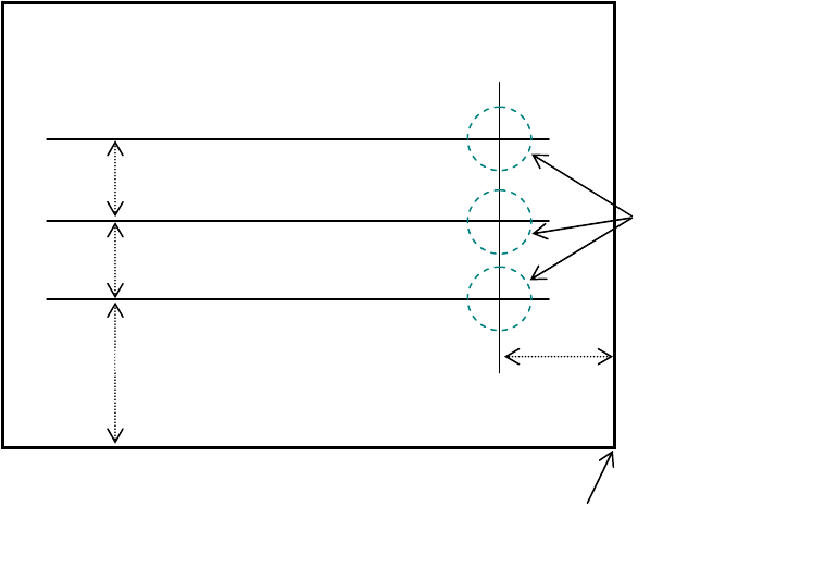
3.1. Preparation for scanning lines
Mark the start line and scanning line by using a chalk (or similar) on the concrete surface to
indicate where to start scanning (starting line) and where to scan (scanning line). Make
sure the start line and the scanning line are orthogonal. As necessary, in order to perform a
re-scan, use the end point of the wall as the reference point for the start line and scanning
line. An example for scanning line is shown in Figure 3-1.
Figure 3-1 Example of scan lines Origin
(End of wall, power outlet etc.)
Scanning line 1
Scanning line 2
Scanning line 3
1m
Start line
2m 1m 1m
These should be
orthogonal
Object to be scanned
(Concrete etc.)
(Wall Surface)

28
3.2. Battery capacity check
Confirm that batteries attached into Smartphone and NJJ-200 sensor unit are sufficiently
charged with the following procedure.
(1) Smartphone battery capacity
NJJ-200 application indicates the battery capacity of Smartphone on the left bottom of the
main screen after the boot-up. (Refer to Figure 4-1 ⑬.) Figure 3-2 shows the remained
capacity of the battery shown by each indication.
: More than 80 % :More than 60% less than 80%
: More than 40% less than 60% :More than 20% less than 40%
: More than 10% less than 20% : Less than 10%
Figure 3-2 Smartphone battery capacity Indication
(2) Sensor unit battery capacity
The battery capacity of the sensor unit can be checked by the LED state after turning on
the sensor unit. For the procedure to confirm the battery capacity by LED state, refer to the
following a). And NJJ-200 application indicates the remained capacity after starting the
communication between Smartphone and the sensor unit. Fo rthe procedure, refer to the
following b).
a) When turning on the sensor unit
After the sensor unit turned on, the function LED blinks and shows the remaiend capacity
of the sensor unit’s battery as shown in Table 3-1.
Table 3-1 Sensor Unit Battery Capacity Indication by Function LED
Remained Capacity Numbers of LED Flashes
More than 75 % 4 flashes repeated 3 times
More than 50 % less than 75 % 3 flashes repeated 3 times
More than 25 % less than 50 % 2 flashes repeated 3 times
Less than 25 % 1 flash repeated 3 times
None No flash
29
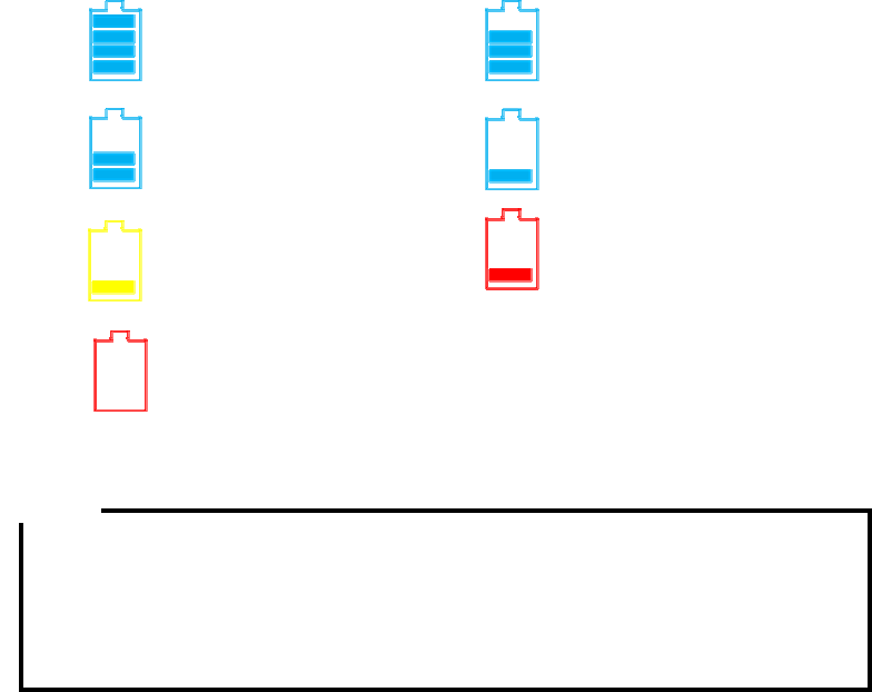
b) When starting the communication between Smartphone and the sensor unit
NJJ-200 application shows the remained capacity of the sensor unit’s battery after starting
the communication between Smartphone and the sensor unit. Figure 3-3 shows the
remained capacity of the battery shown by each indication.
:More than 75% :More than 50% less than 75%
:more than 25% less than 50 :More than 12% less than 25%
:More than 6% less than 12% :Less than 6%
:None
Figure 3-3 Sensor Unit Battery Capacity Indication
y This product supports only the battery as its power source.
y The continuous operation time for the fully charged battery is approx. 7 hours. The
time depends on the operation content. When the continuous operation time is
forecasted beyond 7 hours, the preparation of asecond battery is
recommended.
Note

30
3.3. Scanning
Perform the scan with the following procedure.
(1) Confirm all settings of the product.
The settings to be confirmed are [Display mode] (B/BA) , [Measurement mode]
(Distance/Time), [Color] (Absolute /Offset), [Relative permittivity], and [Sensitivity].
For the setting procedure, refer to Section 4 NJJ-200 application functions. When the
location of the embedded steel bar is known or the width of concrete is known,
perform the depth calibration in accordance with Section 6.1 Relative permittivity
setup.
(2) Place this product on the start line.
The position to be sensed is the cross point of the line between both side LEDs
(Refer to Figure 1-2 ⑪ and ⑰.) and the line between the front and rear LEDs (Refer
to Figure 2-1 ⑫ and ⑱). Place the sensor unit so as to superpose the line between
both side LEDs on the start line (Refer to Figure 3-1) and to superpose the line
between the front and rear LEDs on the scanning line (Refer to Figure 3-1).
(3) Start the scan.
Tap [Start] icon (Refer to Figure 4-1 ① ) on the main screen of Smartphone, or
press [Start] button (Refer to Figure 1-2 ④) on the sensor unit. After one second, a
beep sounds and the fix cursor is displayed on B mode screen.
y The scan is automatically stopped when the sensor unit stays at a position more
than 8 seconds.
(4) Move the sensor unit along with the scan line.
Make sure the moving speed is less than 40cm/s.
y If the speed exceeds beyond 40 cm/s, a beep sounds and the scan becomes
invalid. Any scan data are not obtained during this time. If the sounds, stop the
scan and re-start the scan (from the step (2) above).
(5) As necessary, add antenna markers on the scan screen.
Tap [Marker] icon on the main screen or press [Antenna mark] button on the sensor
unit (Refer to Figure 1-2 ③) to add an antenna mark. When the antenna marker is
added, a mark È is displayed on the distance scale. The antenna marker is useful to
show the location of the rebar shown in the drawing or the position of the planned drill
hole on the scan screen.
Caution
Note
31
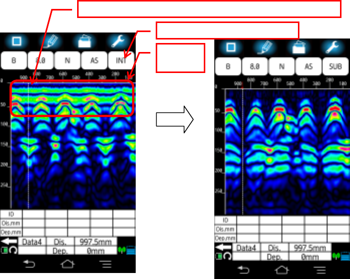
(6) As necessary, perform the image processing of Real time manual subtraction.
Waves reflected by objects to be probed (e.g., reinforcing steel) at a position near the
concrete surface are difficult to identify because they are combined with waves
reflected by the concrete surface (called surface waves). This product contains the
standard surface wave data (fixed surface wave data) with which it eliminates the
influence of the concrete surface waves in real time by subtracting the fixed surface
wave from the received reflection signal. By performing this image processing, you
can more easily identify the object location. However there are some cases for
example, special conditions (very humid surface, lightweight concrete, etc.) of the
concrete surface, where subtracting the fixed surface wave cannot remove the
influence of the surface wave due to the difference between the fixed surface wave
and the actual surface wave. In such case, horizontal lines (noise) may appear near
the surface. In this case, you can use the actually received signal as the surface wave
in place of the fixed surface wave. The image processing using the actually received
surface wave is called real time surface wave processing. The real time surface wave
processing can remove the horizontal lines near by the surface. To use the real time
surface wave processing, move the fixed cursor to the position where any embedded
objects are not detected, then tap [Image processing] icon (Figure 4-1 ⑤). (Refer
to Figure 3-4.)
Figure 3-4 B Mode scan result (during scanning)
① Move the fixed cursor on the position of no embedded object.
②Tap [Image processing] icon.
Surface
wave
32
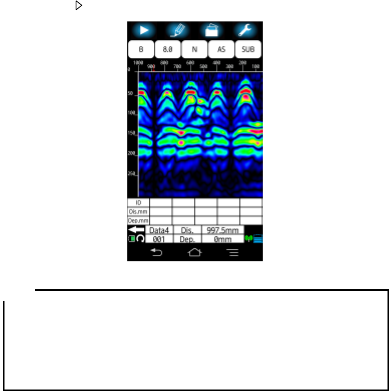
(7) Stop the scan.
Tap [ Start] icon (Refer to Figure 4-1 ①) of the main screen or press [Start] button on
the sensor unit (Refer to Figure 1-2 ④) to stop the scan. Then a beep sounds twice
and the scan is stopped. Figure 3-5 shows an example of the scan result. ([ Start]
icon is displayed as [] during the scan, and after the scan stopped, its shape
changes to [ ].)
Figure 3-5 Example of B mode scan result
y When moving the sensor unit at the speed beyond 40 cm/s, a beep sounds and
the scan becomes invalid. No scan data is obtained during this time.
y The final scanned point of B mode data represents the data obtained at the
position of the line between both side LEDs (Refer to Figure 1-2 ⑪と⑰) of the
sensor unit showing the center of the sensor unit’s built-in antenna.
y The scan is automatically stopped when the sensor unit stays at a position more
than 8 seconds.
(8) As necessary, optimize the sensitivity, color, image processing.
By changing the sensitivity, color, image processing settings, find for the best settings
to get the scan result which provide easy identification of the object position.
(9) Store the data into the file.
Tap [File /Print] icon on the main screen to save the scan data into the file or print out
the scan data to the external printer.
Note
33
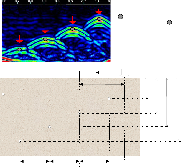
3.4. Interpreting the scan results
Here describes the general procedure to identify position of the detected object.
When the scan result shown in Figure 3-6 is obtained after the rebar detection, the image
of the detected rebar would have the inverse U shape as shown in Figure 3-6. By using
this description, you can determine that a rebar is located at the reverse U shape.
The position of the detected object can be determined from the obtained image as
described below.
Position of the moving direction: Top of the inverse U shape (See È in Figure 3-6)
Rough Depth (Cover width): Center of the inverse U shape (See z in Figure 3-6)
To reduce the depth error of the detected object, perform the depth calibration (Refer to
Section 4.11.1 Device setting: [Relative permittivity) and identify the depth from A mode
wave shown in the BA mode display (Refer to Section 4.6 [Display mode] icon. The depth
of the detected object (a rebar, etc.) is matched with the right side peak of A mode wave.
You can get the exact depth value by moving the cursor exactly on the peak of the A mode
wave.
Figure 3-6 Scan result example
:Position of rebar shown in the
scan results (The mark is
not shown in the actual scan
results.)
200mm 200mm 200mm
60mm
120mm
180mm
240mm
300mm
測定方
スタート
Vertical cross sectional drawing
of objects to be probed
:Φ=10cm reba
r
Measurement direction Start

34
3.5. Power off
After completing all scan works, turn off NJJ-200 by switching the power switch to the OFF
position. For Smartphone, tap Home button of Smartphone to end NJJ-200 application.
y When ending NJJ-200 application without saving the scan result into a file, the
scan data disappear.
y When turning off Smartphone display without ending NJJ-200 application, you
can get the previous screen of NJJ-200 application by turning on the display.
y When NJJ-200 application is ended during the scan, the scan is ended forcedly.
3.6. Shutdown and storage
Make sure to turn off this product after using and put it back into its case.
y When safekeeping this product for a long term, make sure to detach the battery
pack from the sensor unit. If this product is left in the incorrect state for a long
time where the battery pack is not attached fully and the battery pack release
button is pushed down by the battery pack, the battery pack release button may
be damaged and become difficult to be locked due to its shape change.
y When not using this product for a long time, store this product after removing the
battery from the sensor unit.
Note
Caution
Caution