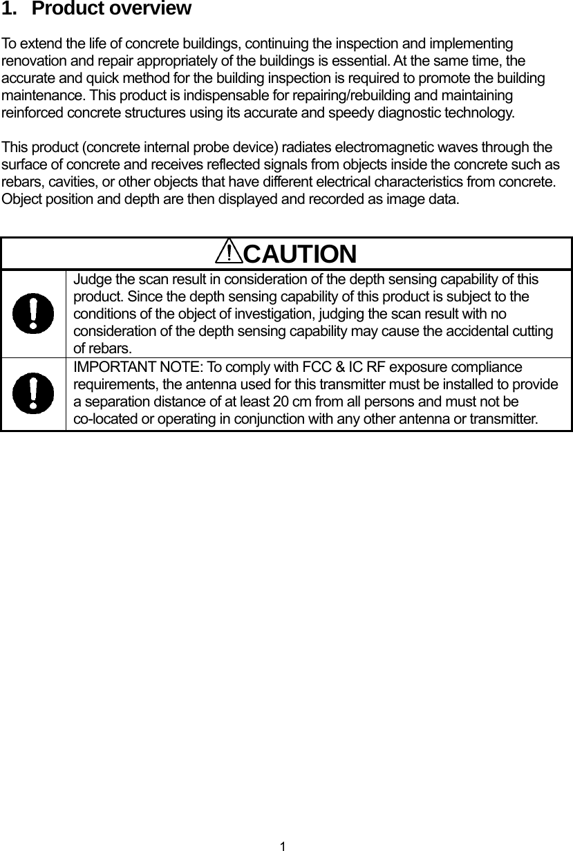
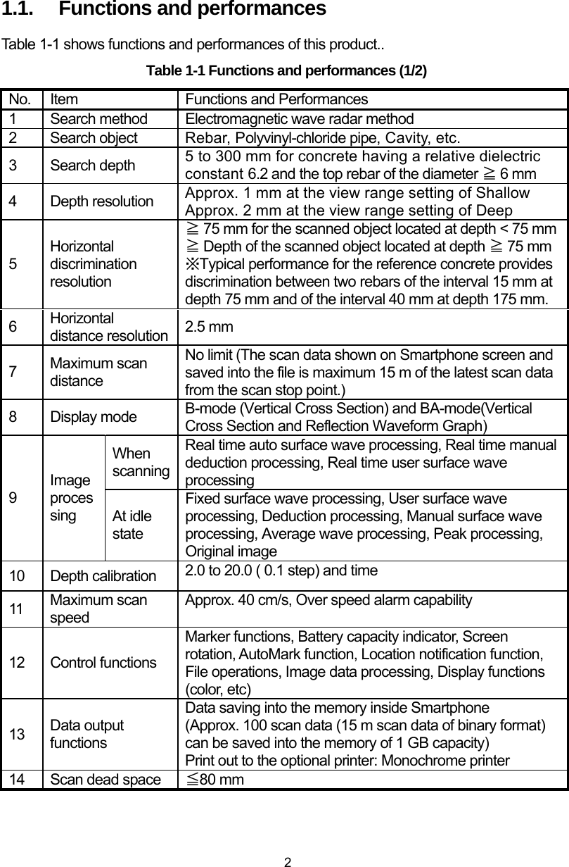
Japan Radio NJJ-200 Handy Search User Manual NJJ 95A
Japan Radio Co Ltd. Handy Search NJJ 95A
UserManual.wiki
>
Japan Radio
>
NJJ-200 User Manual
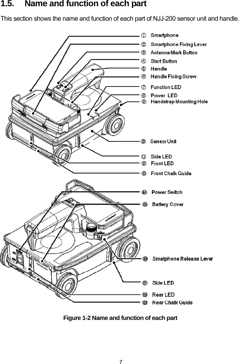
>
Users Manual 1
Contents
1.
Users Manual 1
2.
Users Manual 2
3.
Users Manual 3
4.
Instruction of testing sample
Users Manual 1
Navigation menu
Upload a User Manual
Namespaces
Wiki Guide
HTML
PDF
Info
Views
User Manual
Discussion / Help
Navigation


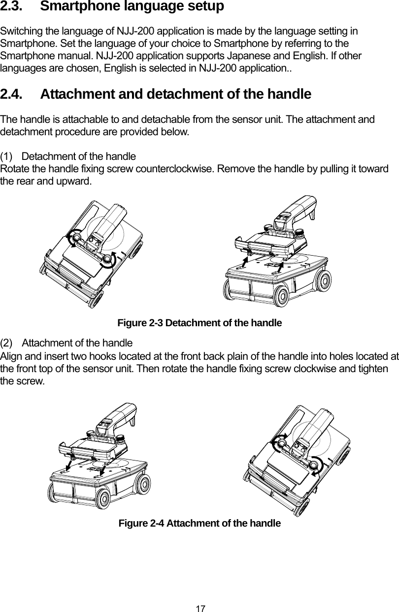
![x 4.3. [MARK] ICON ....................................................................................................... 39 4.3.1. MARKER ADDITION .......................................................................................... 39 4.3.2. MARKER DELETION ......................................................................................... 40 4.3.3. MARKER LIST ................................................................................................... 41 4.4. [FILE/PRINT] ICON .............................................................................................. 43 4.5. [PARAMETER] ICON ............................................................................................. 44 4.5.1. [COLOR] MENU ................................................................................................. 44 4.5.2. [UNIT] MENU .................................................................................................... 46 4.6. [DISPLAY MODE] ICON ......................................................................................... 48 4.7. [RELATIVE PERMITTIVITY] ICON ......................................................................... 49 4.7.1. RELATIVE PERMITTIVITY AND DEPTH CALIBRATION ...................................... 50 4.8. [VIEW RANGE] ICON ............................................................................................ 51 4.9. [SENSITIVITY] ICON ............................................................................................. 52 4.9.1. SENSITIVITY ..................................................................................................... 53 4.10. [IMAGE PROCESSING] ICON ................................................................................. 54 4.10.1. IMAGE PROCESSING ....................................................................................... 55 4.10.2. FIXED SURFACE PROCESSING ....................................................................... 56 4.10.3. USER SURFACE PROCESSING ......................................................................... 56 4.10.4. SUBTRACTION ................................................................................................ 59 4.10.5. MANUAL SURFACE PROCESSING ................................................................... 61 4.10.6. AVERAGING .................................................................................................... 63 4.10.7. PEAK PROCESSING ......................................................................................... 64 4.10.8. ORIGINAL IMAGE ........................................................................................... 65 4.11. PARAMETER SETUP SCREEN ............................................................................... 66 4.11.1. DEVICE SETTING: [RELATIVE PERMITTIVITY] MENU .................................... 67 4.11.2. DEVICE SETTING: [SENSITIVITY] MENU ........................................................ 68 4.11.3. DEVICE SETTING: [VIEW RANGE] MENU ....................................................... 69 4.11.4. DEVICE SETTING: [IMAGE PROCESSING] MENU ........................................... 70 4.11.5. DEVICE SETTING: [COLOR] MENU ................................................................. 71 4.11.6. DEVICE SETTING: [DEVICE ORIENTATION SETTING] MENU ......................... 73 4.11.7. DEVICE SETTING: [UNIT] MENU .................................................................... 74 4.11.8. DEVICE SETTING: [LOCATION NOTIFICATION] MENU ................................... 75 4.11.9. DEVICE SETTING: [SOUND] MENU ................................................................ 75 4.11.10. PREFERRED SETTING: [RELATIVE PERMITTIVITY] MENU .......................... 76 4.11.11. PREFERRED SETTING: [SENSITIVITY] MENU .............................................. 76 4.11.12. PREFERRED SETTING: [RANGE] MENU ....................................................... 77 4.11.13. PREFERRED SETTING: [COLOR] MENU ....................................................... 77 4.11.14. PREFERRED SETTING: [UNIT] MENU .......................................................... 78 4.11.15. SENSOR SETTING: [MEASUREMENT MODE] MENU .................................... 79 4.11.16. SENSOR SETTING: [LED] MENU .................................................................. 80 4.11.17. SENSOR SETTING: [DISTANCE CORRECTION] MENU .................................. 80 4.11.18. SENSOR SETTING: [CHANNEL] MENU ......................................................... 81 4.11.19. OTHER: [SENSOR SELECT] MENU ............................................................... 82 4.11.20. OTHER: [VERSION] MENU ........................................................................... 83 4.11.21. OTHER: [INITIAL SETTING] MENU ............................................................... 84 4.12. FILE OPERATION SCREEN ................................................................................... 85](https://usermanual.wiki/Japan-Radio/NJJ-200.Users-Manual-1/User-Guide-2182936-Page-12.png)
![xi 4.12.1. [OPEN] MENU ................................................................................................. 86 4.12.2. [SAVE/PRINT] MENU ....................................................................................... 87 4.12.3. [SELECT FOLDER] MENU ............................................................................... 88 4.12.4. [DATA NUMBER SETTING] MENU ................................................................... 89 4.13. MARKER OPERATION ........................................................................................... 90 4.13.1. [HIDE MARKERS] MENU ................................................................................ 90 4.13.2. [SHOW MARKER LIST] MENU ......................................................................... 91 4.13.3. [MARKER DETAILS] MENU ............................................................................. 92 4.13.4. [SORT MARKER] MENU .................................................................................. 94 4.13.5. [AUTOMARK] MENU ...................................................................................... 94 4.13.6. [MARKER GROUP SETTING] MENU ................................................................ 95 5. External output ..................................................................... 96 5.1. SAVE THE SCAN RESULT INTO THE FILE ............................................................. 96 5.1.1. BINARY FORMAT ............................................................................................... 96 5.1.2. TEXT FORMAT ................................................................................................... 99 5.2. SAVING THE SCAN DATA .................................................................................... 100 5.3. DATA FILE OPERATION ...................................................................................... 102 5.4. DISPLAYING THUMBNAIL IMAGE OF THE DATA FILE ........................................ 103 5.5. READING THE SCAN DATA FROM THE DATA FILE .............................................. 104 5.6. DELETING THE DATA FILE ................................................................................. 105 5.7. DELETE ALL FILES UNDER THE FOLDER .......................................................... 106 5.8. PRINTER OUTPUT .............................................................................................. 107 5.8.1. PREPARATION FOR THE PRINTER .................................................................. 107 5.8.2. BLUETOOTH PAIRING ...................................................................................... 114 5.8.3. PRINTING SCAN DATA ..................................................................................... 117 6. Application ........................................................................... 120 6.1. RELATIVE PERMITTIVITY SETUP ....................................................................... 120 6.2. PROCEDURE TO MARK THE REBAR ................................................................... 125 6.2.1. FORWARD SCAN MARKING ............................................................................. 125 6.2.2. BACKWARD SCAN MARKING .......................................................................... 126 6.3. AUTOMARK FUNCTION ..................................................................................... 127 6.4. LOCATION NOTIFICATION FUNCTION ............................................................... 133 6.5. SCREEN ROTATION ............................................................................................ 137 6.6. SORT MARKER ................................................................................................... 138 6.7. COMMUNICATION CHANNEL SETUP ................................................................. 141 6.8. DISTANCE ERROR CORRECTION ........................................................................ 142 6.9. SOFTWARE VERSION UP .................................................................................... 143 6.9.1. SMARTPHONE APPLICATION VERSION UP ..................................................... 143 6.9.2. SOFTWARE VERSION UP FOR SENSOR UNIT .................................................. 149 7. Battery pack and battery charger ...................................... 153 7.1. BATTERY PACK HST30002 ............................................................................... 154 7.2. BATTERY CHARGER PPT20003 ........................................................................ 155](https://usermanual.wiki/Japan-Radio/NJJ-200.Users-Manual-1/User-Guide-2182936-Page-13.png)
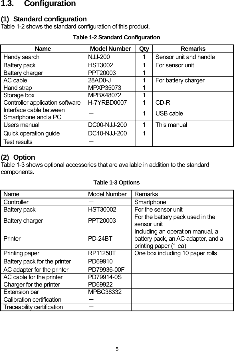
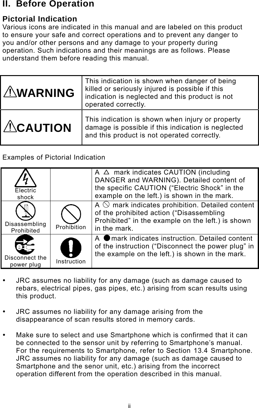
![11 2.2. NJJ-200 application installation Install NJJ-200 application into Smartphone with the following procedure. (1) Copy NJJ-200 application file from PC to Smartphone with the following procedure. NJJ-200 application file is provided in the CD-R attached to this product. By connecting Smartphone and a PC by using a USB cable (or a micro USB cable), Smartphone can be recognized and mounted as a removal data drive on the PC, then the file copy operation of drag and drop become available. By using this capability, copy NJJ-200 application from the PC to Smartphone. a) On Smartphone, enable the file operation on Smartphone’s memory card from the PC by setting Smartphone into Card reader mode or File transfer mode (MSC). For the detailed procedure, refer to the manual attached to Smartphone. Example: Tap [Setting], [Device setting], [External Connection], [USB Connection], then [Card reader mode]. b) Connect Smartphone to a USB port of the PC by using a micro USB cable. c) On Smartphone, tap [Turn on USB Storage]. d) On the PC, Confirm that Smartphone’s data storage is recognized and mounted as a removal data drive on the PC. e) Create the folder “NJJ200” in Smartphone data drive mounted in steps above. f) Insert the furnished CD-R into the CD-R Drive of the PC. g) Copy NJJ-200 application file (File name: “NJJ-200.apk”) on the CD-R to the folder “NJJ200” on Smartphone by using the drag and drop capability. h) Remove the drive of Smartphone from the PC by using the PC function of the safety hardware removal. i) On Smartphone, tap [Turn off USB storage].](https://usermanual.wiki/Japan-Radio/NJJ-200.Users-Manual-1/User-Guide-2182936-Page-25.png)
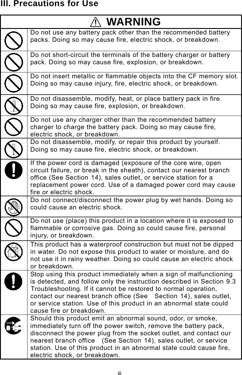
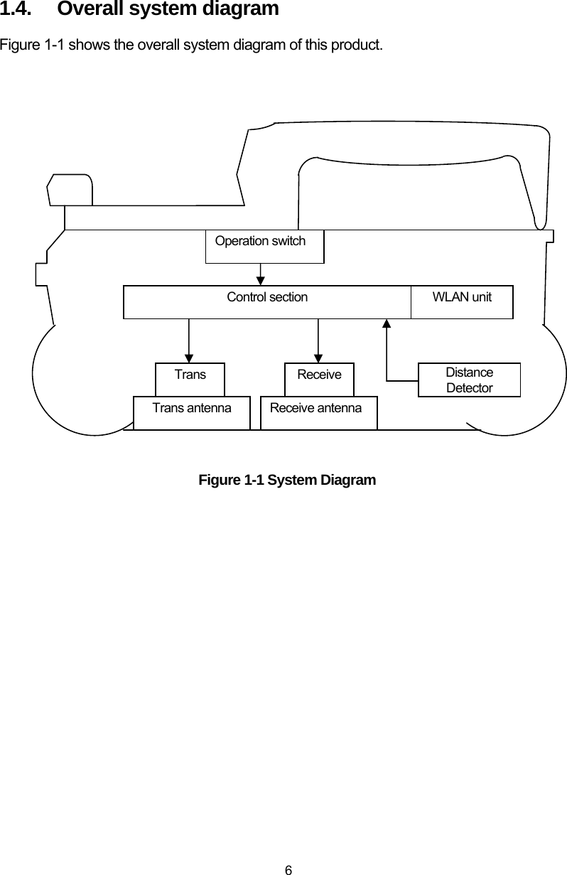
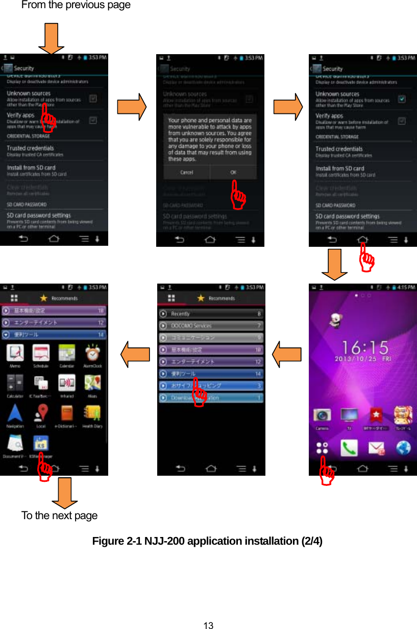
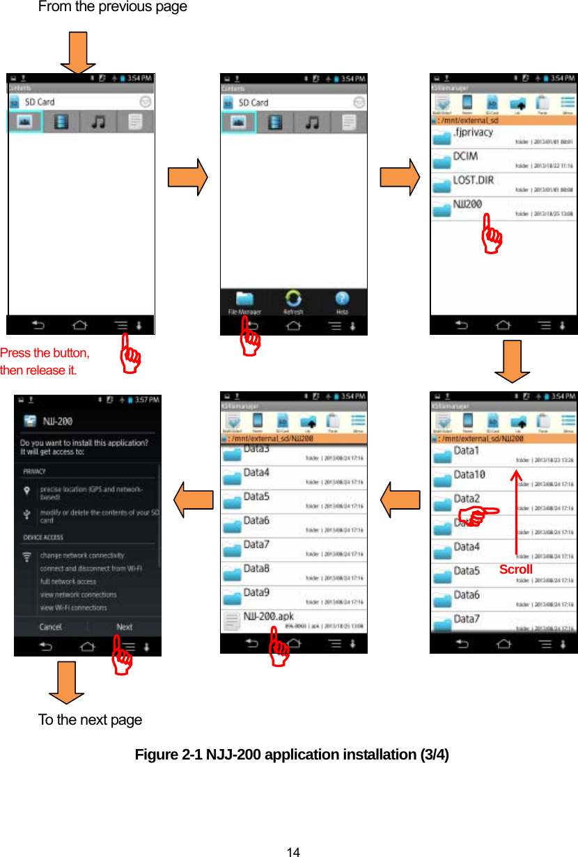
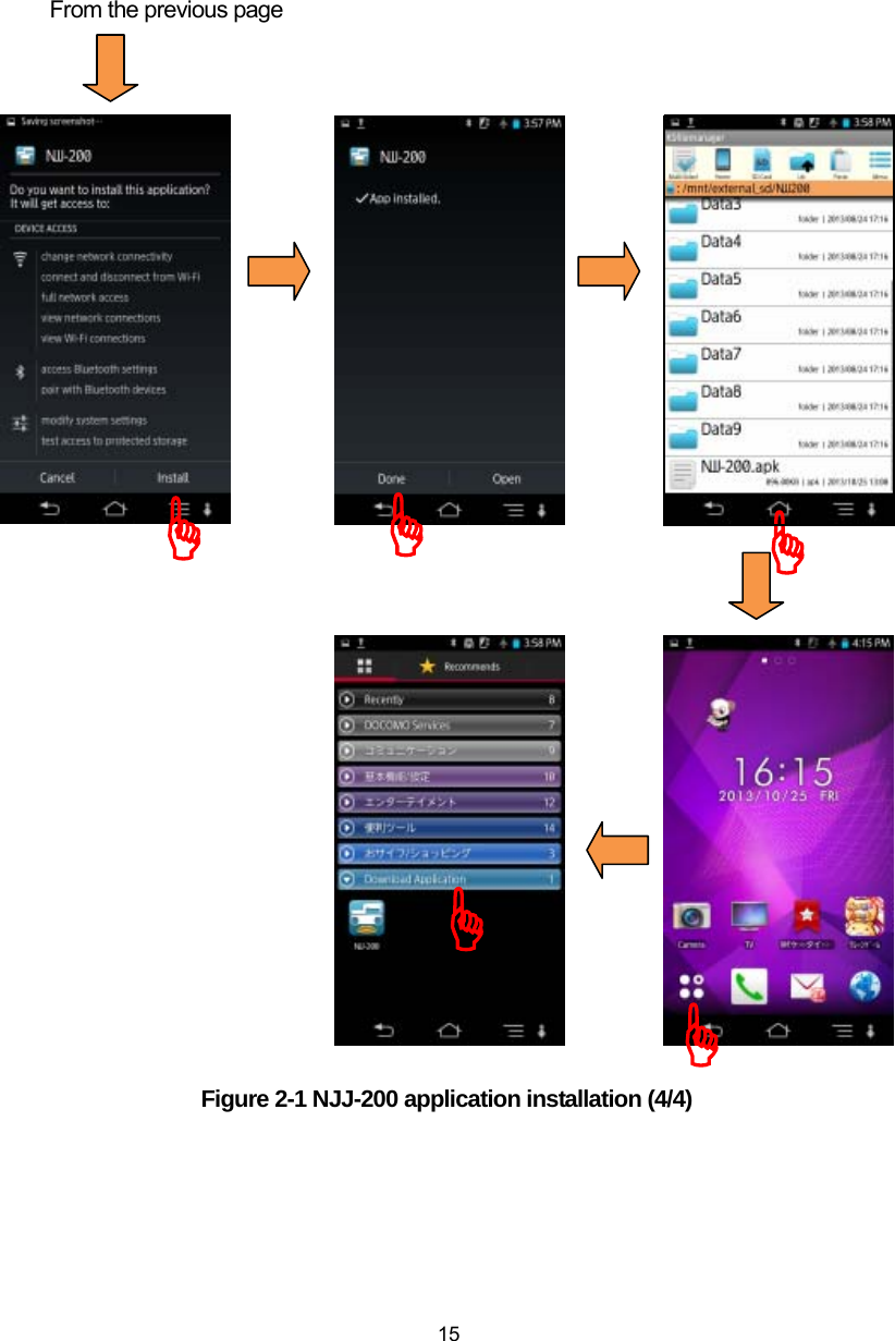
![12 (2) Install NJJ-200 application into Smartphone with the following procedure. a) At the security setting in Smartphone, set the setting so as to allow the installation of applications from the unknown sources. For the detailed procedure, refer to the manual attached to Smartphone. Example: Tap [Setting], [Device setting], [Lock & Security], and tap [Unknown source]. b) Activate the file management application (Contents manager, File commander, etc.) in Smartphone. Then install NJJ-200 application by tapping [NJJ-200] which was copied into the memory card of Smartphone. Make sure [NJJ-200] icon is registered in [Downloaded] at [Application] screen on Smartphone. If the icon is not registered, check if steps (1) and (2) above have been done correctly. Figure 2-1shows an example of NJJ-200 application installation procedure. To the next page Figure 2-1 NJJ-200 application installation (1/4) )))](https://usermanual.wiki/Japan-Radio/NJJ-200.Users-Manual-1/User-Guide-2182936-Page-26.png)
![16 (1) NJJ-200 application operational verification Make sure that NJJ-200 application is properly installed in Smartphone by the following procedures (Refer to Figure 2-2). If it displays the main screen of NJJ-200 application, the installation is completed successfully. a) Turn on Smartphone. Wait a little, then the home screen of Smartphone appears. b) Tap [Application] icon in the home screen of Smartphone. c) Tap [NJJ-200] icon shown in [Download Application] to run NJJ-200 application. Then an opening screen of NJJ-200 application appears as shown, then the main screen of NJJ-200 application appears. Figure 2-2 NJJ-200 application boot-up screen ))](https://usermanual.wiki/Japan-Radio/NJJ-200.Users-Manual-1/User-Guide-2182936-Page-30.png)
![21 2.8. Communication setup Use the following procedure to establish the communication between the sensor unit and Smartphone through wireless LAN. (1) Make sure the battery pack is installed and the sensor unit is switched to ON position. (2) Turn on Smartphone. Home screen of Smartphone will appear after a while. (3) Set Smartphone to Airplane mode. (4) Tap [Application] icon on the home screen. (5) Tap [NJJ-200] icon in [Downloaded application]. Then the opening screen of NJJ-200 application appears and shows the main screen automatically. (6) Long tap [Parameter] icon. Then the parameter setup screen appears. (7) Tap [Sensor select] menu in the parameter setup screen. Then the sensor select screen appears and lists sensor units available nearby Smartphone. (8) Tap the ID of the used sensor unit in the sensor select screen. (9) Return to the main screen. Then the communication between Smartphone and the sensor unit is established, and the antenna icon turns from red to green and the color of the sensor unit’s power LED changes from red to green. Figure 2-8 Communication setup Long tap the setting icon, then the setting screen appears. Scroll the setting screen, and tap the sensor selection. Tap the ID of the used sensor unit in the shown ID list. Return to the main screen. Then the color of the antenna icon changes to green. )))](https://usermanual.wiki/Japan-Radio/NJJ-200.Users-Manual-1/User-Guide-2182936-Page-35.png)
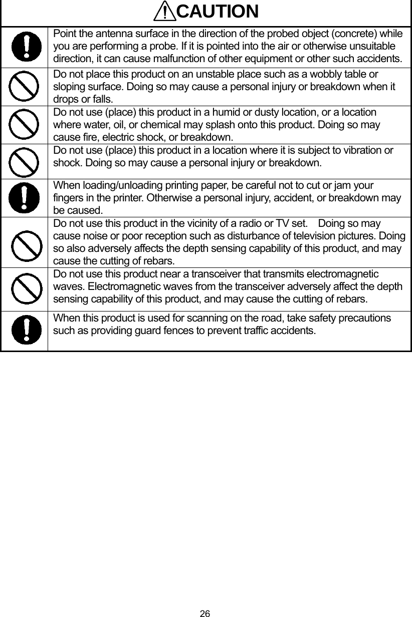
![22 Notes on wireless communication: y Some devices operate using the same frequency bands adopted by this product. Equipment such as microwave ovens and other home electronics, radios and equipment used in various types of radio stations including Amateur Radio stations, and devices that operate on industrial, scientific, or medical frequency bands may experience interference from this product. y In case any harmful radio interference occurred, immediately stop to use this product. Then contact to one of our contact points described in Section 14 or the distributor from which you purchased this product to get consultation about the solution. y y Make sure that Smartphone is set to Airplane mode:ON. If NJJ-200 application is started on Smartphone with Airplane mode:OFF, a message “Could not be set to airplane mode.” appears. If such a messages appears, tap the [OK], then stop NJJ-200 application. Set Smartphone to be in Airplane mode, then restart NJJ-200 application. y Use this product in the area of small electrical and magnetic noise. Otherwise , especially when using near a microwave oven, this product may be influenced by magnetic or electrical noise, resulting noise level increased in the scan result or unstable communication between the sensor unit and Smartphone. y If used near TV or radio, harmful interference (including TV image distortion) may occur. y If the same channel is used by nearby wireless LAN access points, NJJ-200 application may not detect available sensor units correctly. In such case, change the communication channel by referring to Section 6.7 Communication channel setup. Caution](https://usermanual.wiki/Japan-Radio/NJJ-200.Users-Manual-1/User-Guide-2182936-Page-36.png)
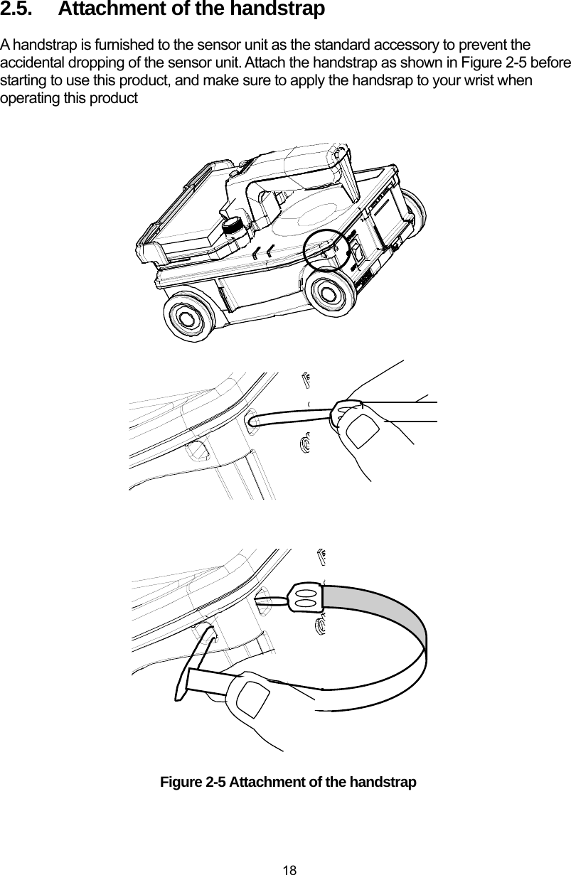
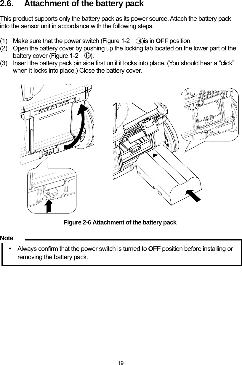
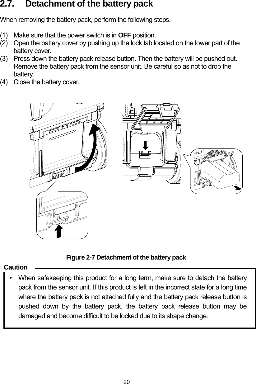
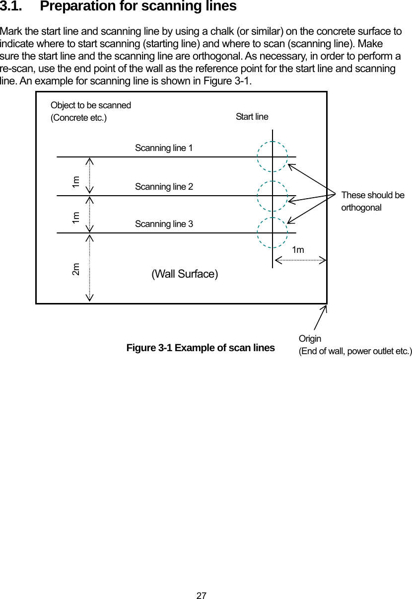
![25 3. Basic scan procedure This section describes the basic scan procedure. The following description assumes all the preparations described in Section 2 have been completed successfully. If some preparations have not been made yet, complete all the preparations in accordance with Section 2. In the following description, each icon or button displayed in NJJ-200 application is referred by using [its name]. WARNING Do not use any battery pack other than the recommended battery packs. Doing so could cause fire, electric shock, or breakdown. Do not short-circuit the terminals of the battery charger or battery pack. Doing so could cause fire, explosion, or breakdown. Do not insert anything metallic or flammable into the battery pack slot. Doing so could cause a personal injury, fire, electric shock, or breakdown. Do not use any charger other than the dedicated battery charger to charge the battery pack. Doing so could cause fire, electric shock, or breakdown. Do not use (place) this product in a location where it is exposed to flammable or corrosive gas. Doing so could cause fire, personal injury, or breakdown. Handy Search has a waterproof construction but must not be placed in water. Do not expose this product to water or moisture, and do not use it in rainy weather. Doing so could cause an electric shock or breakdown. CAUTION Making a judgment on the scan results considers the depth scan capability of this product. Since the depth scan capability of this product is subject to the conditions of the object of investigation, judging the scan results with no consideration of the depth scan capability may cause the cutting of rebars. Put your hand through the hand strap and hold this product. Dropping of this product may cause an accident such as a device breakdown or personal injury.](https://usermanual.wiki/Japan-Radio/NJJ-200.Users-Manual-1/User-Guide-2182936-Page-39.png)
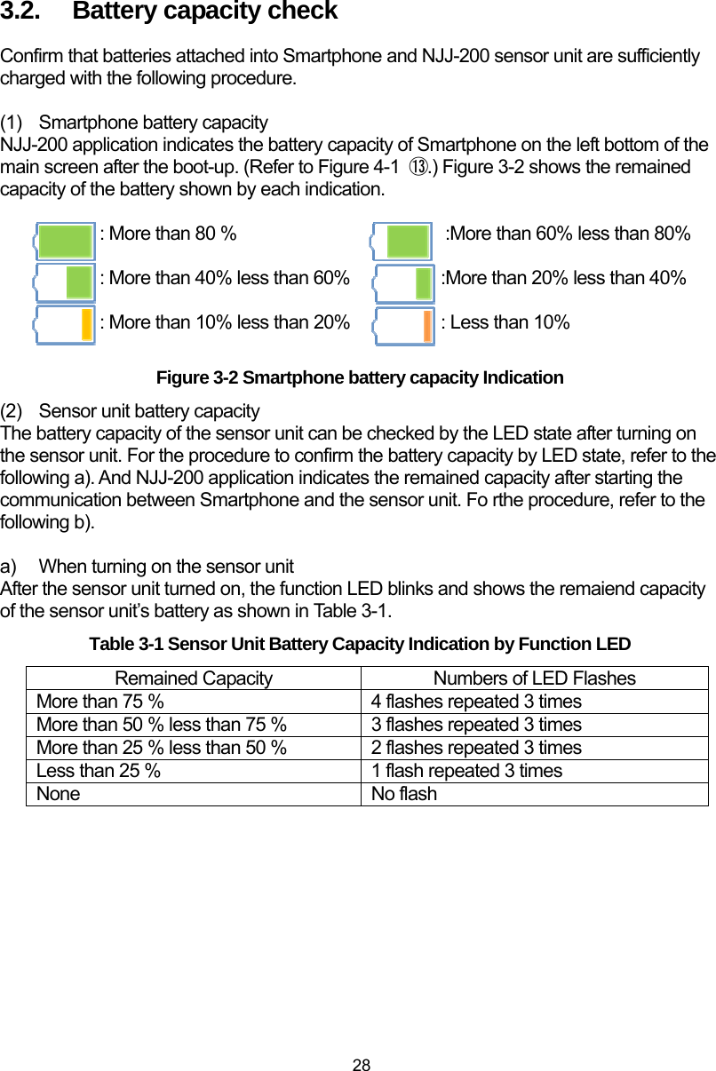
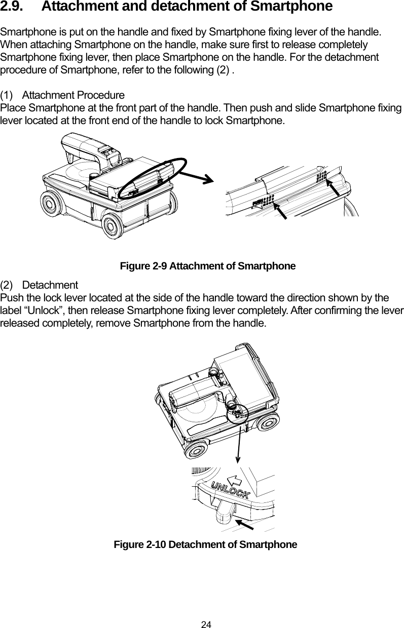
![30 3.3. Scanning Perform the scan with the following procedure. (1) Confirm all settings of the product. The settings to be confirmed are [Display mode] (B/BA) , [Measurement mode] (Distance/Time), [Color] (Absolute /Offset), [Relative permittivity], and [Sensitivity]. For the setting procedure, refer to Section 4 NJJ-200 application functions. When the location of the embedded steel bar is known or the width of concrete is known, perform the depth calibration in accordance with Section 6.1 Relative permittivity setup. (2) Place this product on the start line. The position to be sensed is the cross point of the line between both side LEDs (Refer to Figure 1-2 ⑪ and ⑰.) and the line between the front and rear LEDs (Refer to Figure 2-1 ⑫ and ⑱). Place the sensor unit so as to superpose the line between both side LEDs on the start line (Refer to Figure 3-1) and to superpose the line between the front and rear LEDs on the scanning line (Refer to Figure 3-1). (3) Start the scan. Tap [Start] icon (Refer to Figure 4-1 ① ) on the main screen of Smartphone, or press [Start] button (Refer to Figure 1-2 ④) on the sensor unit. After one second, a beep sounds and the fix cursor is displayed on B mode screen. y The scan is automatically stopped when the sensor unit stays at a position more than 8 seconds. (4) Move the sensor unit along with the scan line. Make sure the moving speed is less than 40cm/s. y If the speed exceeds beyond 40 cm/s, a beep sounds and the scan becomes invalid. Any scan data are not obtained during this time. If the sounds, stop the scan and re-start the scan (from the step (2) above). (5) As necessary, add antenna markers on the scan screen. Tap [Marker] icon on the main screen or press [Antenna mark] button on the sensor unit (Refer to Figure 1-2 ③) to add an antenna mark. When the antenna marker is added, a mark È is displayed on the distance scale. The antenna marker is useful to show the location of the rebar shown in the drawing or the position of the planned drill hole on the scan screen. Caution Note](https://usermanual.wiki/Japan-Radio/NJJ-200.Users-Manual-1/User-Guide-2182936-Page-44.png)
![31 (6) As necessary, perform the image processing of Real time manual subtraction. Waves reflected by objects to be probed (e.g., reinforcing steel) at a position near the concrete surface are difficult to identify because they are combined with waves reflected by the concrete surface (called surface waves). This product contains the standard surface wave data (fixed surface wave data) with which it eliminates the influence of the concrete surface waves in real time by subtracting the fixed surface wave from the received reflection signal. By performing this image processing, you can more easily identify the object location. However there are some cases for example, special conditions (very humid surface, lightweight concrete, etc.) of the concrete surface, where subtracting the fixed surface wave cannot remove the influence of the surface wave due to the difference between the fixed surface wave and the actual surface wave. In such case, horizontal lines (noise) may appear near the surface. In this case, you can use the actually received signal as the surface wave in place of the fixed surface wave. The image processing using the actually received surface wave is called real time surface wave processing. The real time surface wave processing can remove the horizontal lines near by the surface. To use the real time surface wave processing, move the fixed cursor to the position where any embedded objects are not detected, then tap [Image processing] icon (Figure 4-1 ⑤). (Refer to Figure 3-4.) Figure 3-4 B Mode scan result (during scanning) ① Move the fixed cursor on the position of no embedded object. ②Tap [Image processing] icon. Surface wave](https://usermanual.wiki/Japan-Radio/NJJ-200.Users-Manual-1/User-Guide-2182936-Page-45.png)
![32 (7) Stop the scan. Tap [ Start] icon (Refer to Figure 4-1 ①) of the main screen or press [Start] button on the sensor unit (Refer to Figure 1-2 ④) to stop the scan. Then a beep sounds twice and the scan is stopped. Figure 3-5 shows an example of the scan result. ([ Start] icon is displayed as [] during the scan, and after the scan stopped, its shape changes to [ ].) Figure 3-5 Example of B mode scan result y When moving the sensor unit at the speed beyond 40 cm/s, a beep sounds and the scan becomes invalid. No scan data is obtained during this time. y The final scanned point of B mode data represents the data obtained at the position of the line between both side LEDs (Refer to Figure 1-2 ⑪と⑰) of the sensor unit showing the center of the sensor unit’s built-in antenna. y The scan is automatically stopped when the sensor unit stays at a position more than 8 seconds. (8) As necessary, optimize the sensitivity, color, image processing. By changing the sensitivity, color, image processing settings, find for the best settings to get the scan result which provide easy identification of the object position. (9) Store the data into the file. Tap [File /Print] icon on the main screen to save the scan data into the file or print out the scan data to the external printer. Note](https://usermanual.wiki/Japan-Radio/NJJ-200.Users-Manual-1/User-Guide-2182936-Page-46.png)
![33 3.4. Interpreting the scan results Here describes the general procedure to identify position of the detected object. When the scan result shown in Figure 3-6 is obtained after the rebar detection, the image of the detected rebar would have the inverse U shape as shown in Figure 3-6. By using this description, you can determine that a rebar is located at the reverse U shape. The position of the detected object can be determined from the obtained image as described below. Position of the moving direction: Top of the inverse U shape (See È in Figure 3-6) Rough Depth (Cover width): Center of the inverse U shape (See z in Figure 3-6) To reduce the depth error of the detected object, perform the depth calibration (Refer to Section 4.11.1 Device setting: [Relative permittivity) and identify the depth from A mode wave shown in the BA mode display (Refer to Section 4.6 [Display mode] icon. The depth of the detected object (a rebar, etc.) is matched with the right side peak of A mode wave. You can get the exact depth value by moving the cursor exactly on the peak of the A mode wave. Figure 3-6 Scan result example :Position of rebar shown in the scan results (The mark is not shown in the actual scan results.) 200mm 200mm 200mm 60mm 120mm180mm 240mm 300mm 測定方スタートVertical cross sectional drawing of objects to be probed :Φ=10cm rebarMeasurement direction Start](https://usermanual.wiki/Japan-Radio/NJJ-200.Users-Manual-1/User-Guide-2182936-Page-47.png)