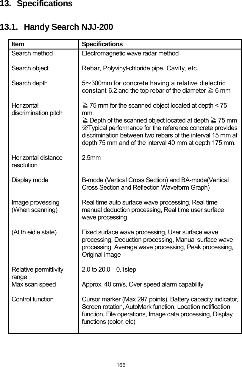
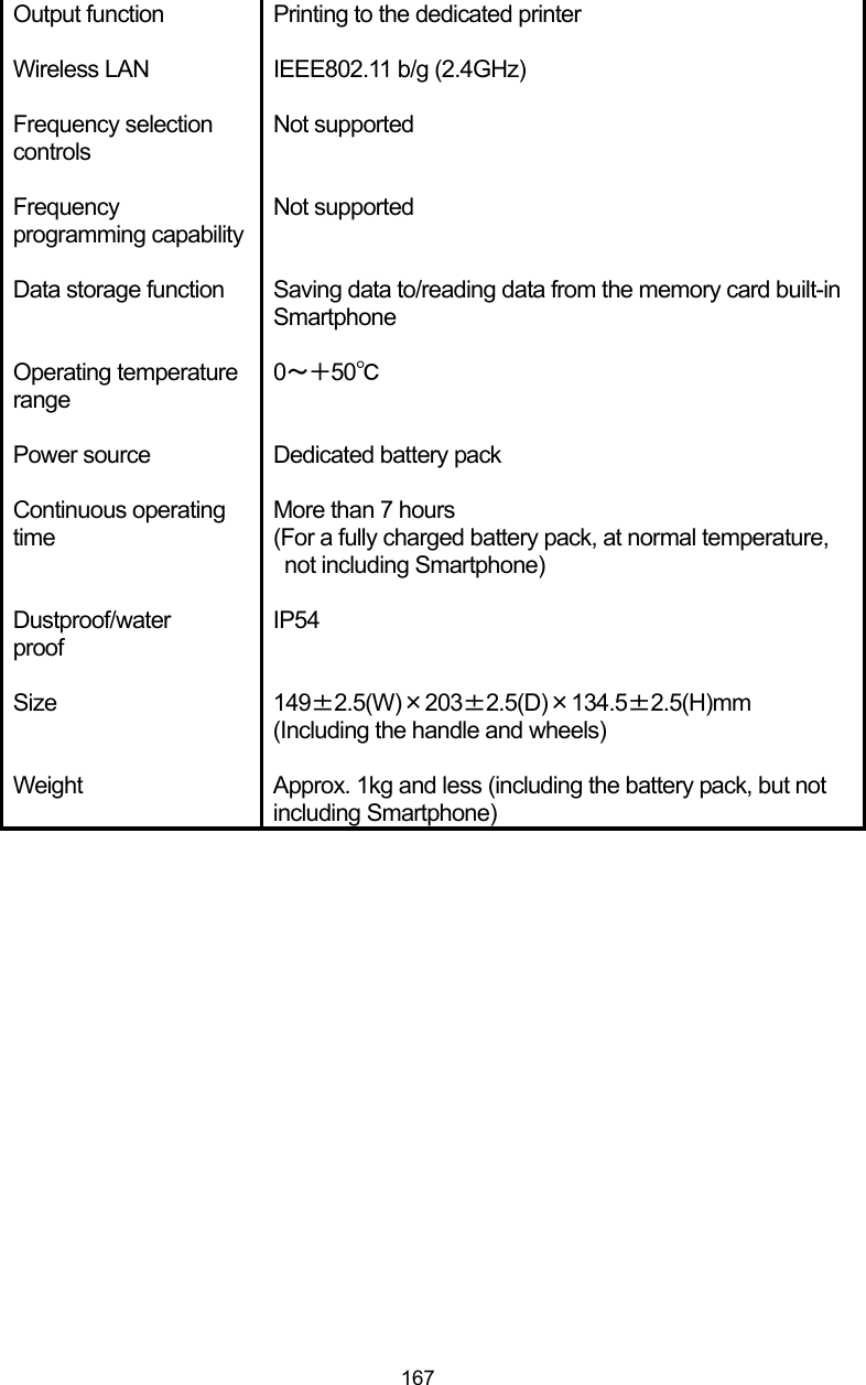
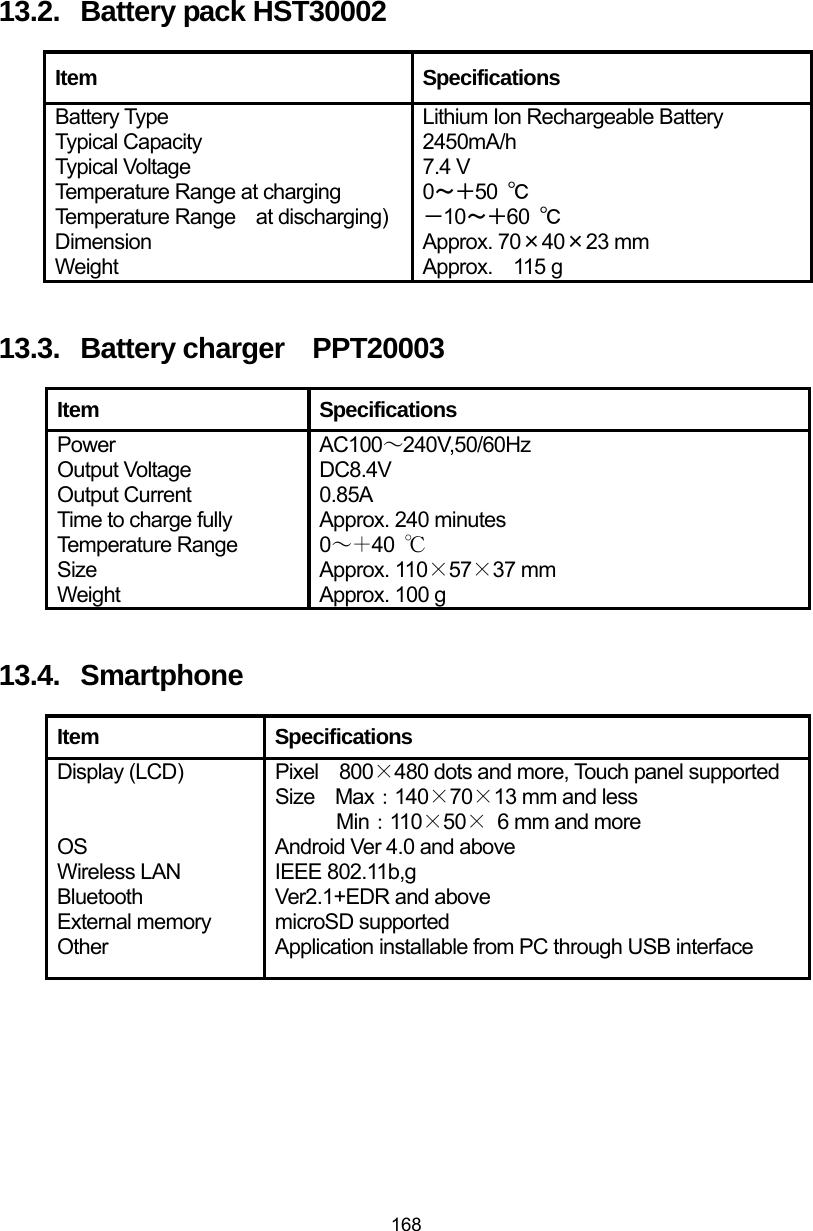
Japan Radio NJJ-200 Handy Search User Manual NJJ 95A
Japan Radio Co Ltd. Handy Search NJJ 95A
UserManual.wiki
>
Japan Radio
>
NJJ-200 User Manual
>
Users Manual 3
Contents
1.
Users Manual 1
2.
Users Manual 2
3.
Users Manual 3
4.
Instruction of testing sample
Users Manual 3
Navigation menu
Upload a User Manual
Namespaces
Wiki Guide
HTML
PDF
Info
Views
User Manual
Discussion / Help
Navigation
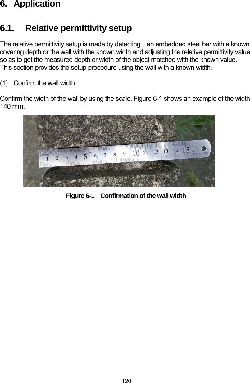
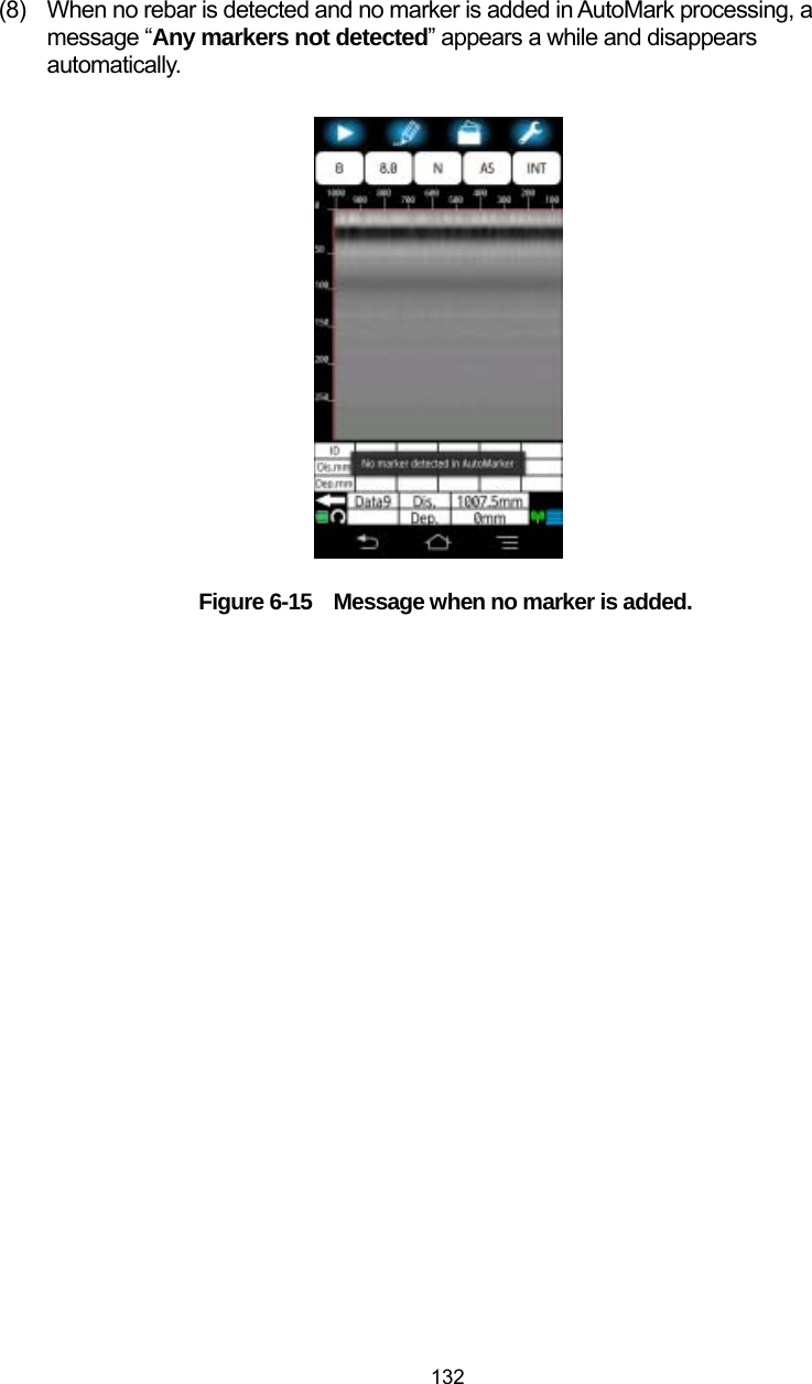
![121 (2) Scan the wall Scan the wall with the relative permittivity 8.0 of the sensor unit. For the procedure to set the relative permittivity of the sensor, refer to Section 4.11.1 Device setting: [Relative permittivity] menu) The reflection wave from the opposite side of the wall appears on the main screen as the shape of the horizontal band as shown in Figure 6-2. Move the horizontal cursor on the edge of the horizontal band. The depth value of the cursor is displayed in the cursor coordinate. (In the example of Figure 6-2, the depth is 127 mm.) Figure 6-2 Scan of the wall The reflection from the wall is shown as a horizontal band.Align the cursor on the reflection from the wall. The depth value of the cursor shows the width of the wall.](https://usermanual.wiki/Japan-Radio/NJJ-200.Users-Manual-3/User-Guide-2182938-Page-2.png)
![122 (3) Show the relative permittivity setup screen. Tap [Relative permittivity] icon to show the relative permittivity setup screen. The current depth of the cursor position is shown in the screen. Figure 6-3 Relative permittivity setup screen Here shows the depth of the current cursor position. )](https://usermanual.wiki/Japan-Radio/NJJ-200.Users-Manual-3/User-Guide-2182938-Page-3.png)
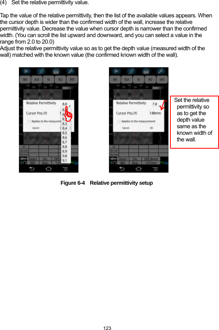
![124 (5) Register the relative permittivity in the device setup screen. Tap [□Applies to the measurement], then confirm a mark 9 is shown in the [□]. With this, the relative permittivity value is registered to [Device setup: Relative permittivity] menu in the parameter setup screen. Then tap [OK] to complete the relative permittivity setup, then the screen returns to the main screen. Figure 6-5 Relative permittivity setup y When tapping [OK] without putting 9 into [□Applies to the measurement], the new relative permittivity is applied only to the scan image displayed currently, but not to the relative permittivity of the device setup which is used in scanning. The next scanning is made by using the original relative permittivity in the [Device setup: Relative permittivity] menu, but not using the new value defined in the procedure above. ))Caution](https://usermanual.wiki/Japan-Radio/NJJ-200.Users-Manual-3/User-Guide-2182938-Page-5.png)
![128 (1) Display the scan image on the main screen by performing a scan or reading the scan data from the file, then long tap [Mark] icon. Figure 6-8 Long tap [Mark] icon (2) The marker operation screen shown in Figure 6-9 appears. Tap [AutoMark] menu. Figure 6-9 Tap [AutoMark] menu ))](https://usermanual.wiki/Japan-Radio/NJJ-200.Users-Manual-3/User-Guide-2182938-Page-9.png)
![129 (3) AutoMark screen shown in Figure 6-10 appears. The marker group into which AutoMark function adds markers is shown at the top of the screen. Confirm the marker group is correct. To change the marker group, refer to Section 4.13.6 [Marker group setting] menu. Figure 6-10 Confirmation of the marker group (4) Tap [Search from the start] when searching the rebar from the start of the scan data. When searching the rebar from the end of scan data, tap [Search from the end]. Then confirm ● mark is attached to the selected setting. Figure 6-11 Search direction setup Confirm the marker group. ))](https://usermanual.wiki/Japan-Radio/NJJ-200.Users-Manual-3/User-Guide-2182938-Page-10.png)
![130 (5) Tap [OK] to execute AutoMark function. To cancel Auto Mark function, tap [Cancel], then the screen returns to the main screen. Figure 6-12 AutoMark execution (6) A message “Automarker processing…” shown in Figure 6-13 appears. Figure 6-13 AutoMarker processing )](https://usermanual.wiki/Japan-Radio/NJJ-200.Users-Manual-3/User-Guide-2182938-Page-11.png)
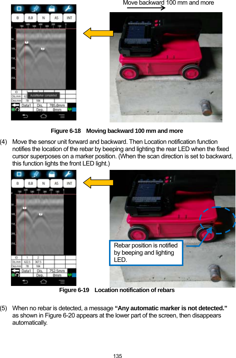
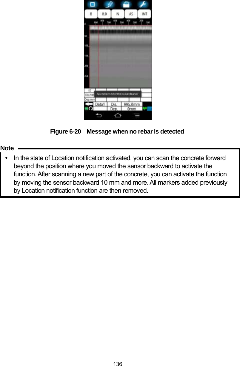
![134 (1) Long tap [Parameter setup] icon to show the parameter setup screen. Then turn Location notification function to ON by tapping [Location notification] menu. Then tap [Return to the main window]. Figure 6-16 Turn Location notification function on (2) Execute the scan. Figure 6-17 Scanning (3) Move the sensor unit backward 10 mm and more. Then Location notification function is activated and adds markers automatically on the position of rebars. )))](https://usermanual.wiki/Japan-Radio/NJJ-200.Users-Manual-3/User-Guide-2182938-Page-15.png)
![137 6.5. Screen rotation You can rotate the screen 90 degrees and show the scan result as shown in Figure Figure 6-21by tapping [Screen rotate] icon. The horizontal display can show the scan result of 6 m distance on one screen and is helpful to grasp the entire rebar layout of the floor and ceiling. 1) Vertical display 2)Horizontal display Figure 6-21 Screen rotation ))](https://usermanual.wiki/Japan-Radio/NJJ-200.Users-Manual-3/User-Guide-2182938-Page-18.png)
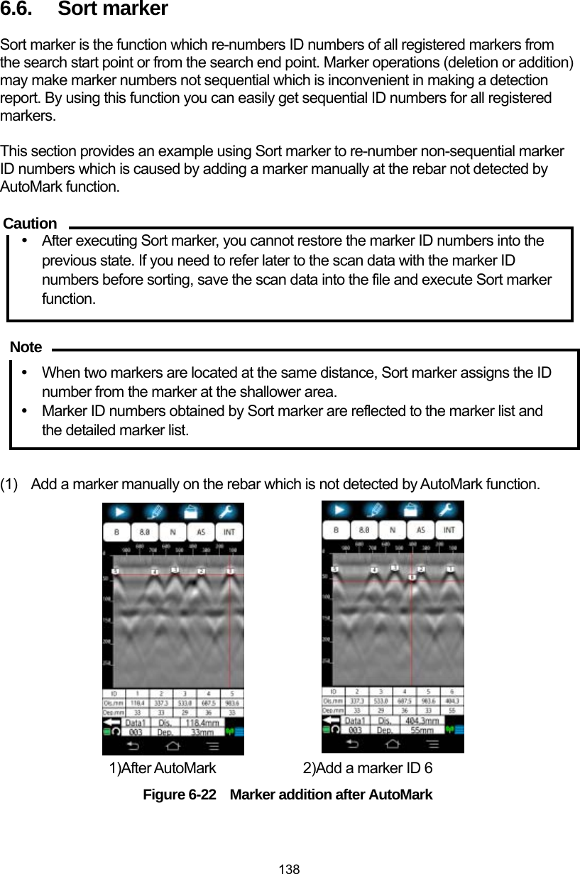
![139 (2) Long tap [Mark] icon to show the marker operation screen and tap [Sort marker] menu in the marker operation screen. Then the sort marker screen appears. Figure 6-23 Sort marker screen (3) Tap [Ascending order] to sort marker ID numbers from the scan start position. To sort from the scan end position, tap [Descending order]. Confirm the ● mark is attached to the selected order. 1) Ascending order 2) Descending order Figure 6-24 Sort order setup ))))](https://usermanual.wiki/Japan-Radio/NJJ-200.Users-Manual-3/User-Guide-2182938-Page-20.png)
![140 (4) Tap [OK] to return to the main screen. To cancel Sort marker, tap [Cancel], then the screen returns to the main screen. 1) Ascending order 2) Descending order Figure 6-25 Sort marker result](https://usermanual.wiki/Japan-Radio/NJJ-200.Users-Manual-3/User-Guide-2182938-Page-21.png)
![141 6.7. Communication channel setup The communications channel sets the channel used by the wireless LAN communication between the sensor unit and Smartphone. When the wireless LAN communication between Smart phone and the sensor unit is not established or drops frequently, change the communication channel. The available channels are 0 to 11. When setting a channel 0, the sensor unit sets a channel randomly (The factory setting of the communication channel is 0.) You can set the communication channel with the following procedure. (1) Long tap [Parameter] icon. The parameter setup screen appears. (2) Tap [Channel] menu. Then the channel setup screen shown in Figure 6-26 appears and shows the current channel selected. (3) Tap the channel number (in the case of Figure 6-26, tap 0). Then the list of the available channel numbers appears. (4) Tap a number in the list as the communication channel used. Then confirm the selected channel number is shown in the channel setup screen. (5) Tap [OK] to return to the parameter setup screen. To cancel the channel change, tap [Cancel], then the screen returns to the parameter setup screen. (6) Tap [Return to the main window] to return to the main screen. Figure 6-26 Channel setup screen y The communication channel setup is available only when the communication between Smartphone and the sensor unit is established. When tapping [Channel] menu when no communication is established, the channel setup screen does not appear. y The changed communication channel becomes valid when NJJ-200 application boots up at the next time. Caution](https://usermanual.wiki/Japan-Radio/NJJ-200.Users-Manual-3/User-Guide-2182938-Page-22.png)
![142 6.8. Distance error correction In using this product, eventual wear of the tires may cause distance error. This product has the capability to measure the moving distance by measuring the rotation of the wheel. When the distance error occurs, perform the distance error correction in accordance with the following procedure. (1) Scan the concrete of 1 m distance (actual length). Then stop the scan. (2) Long tap [Parameter] icon to show the parameter setup screen. (3) Tap [Distance correction] menu to show the distance correction screen. (4) Tap the shown distance correction value. Then the list of the available distance correction values appears. (5) Tap a value in the list as the distance correction value. (6) Repeat Steps (4) and (5) so as to get the distance value shown at the right of the distance correction screen being nearest to 1 m. (7) Tap [OK] to return to the parameter setup screen. Then tap [Return to the main window], then the screen returns to the main screen. y The measured distance at the scan end line is shown at the left of the correction value. When changing the correction value, the distance value is recalculated and changes. You can use this distance value for the distance error correction. y The distance correction value become effective from the next new scan, but not reflected to the exiting scan results. y For the scan data of the distance more than 10 m scanned with the distance correction ≥ 13, when printing it in Wide (“W”) view range (Shallow W, Normal W, Depth W), the printed image may be difficult to recognize. Note](https://usermanual.wiki/Japan-Radio/NJJ-200.Users-Manual-3/User-Guide-2182938-Page-23.png)
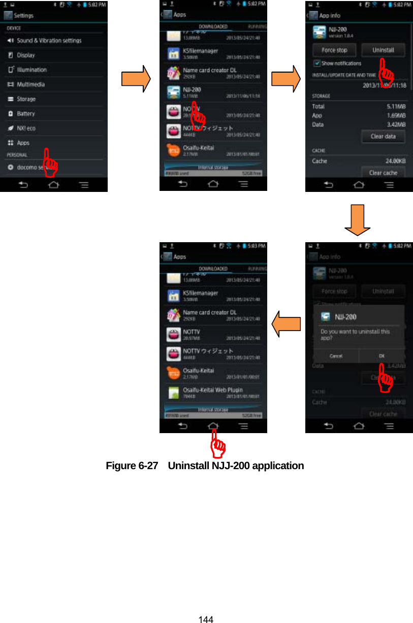
![143 6.9. Software version up 6.9.1. Smartphone application version up You can update the version for NJJ-200 application software by using Smartphone function. The function to update the application version depends on the model of Smartphone. For the details of the procedure, refer to the Smartphone manual. This section describes an example of the setup procedure of Smartphone for NJJ-200 application software version upgrade. (1) Uninstall NJJ-200 application software from Smartphone by performing the following procedure. a) Tap [Settings], [Deice settings], [Application] to show the all list of the installed applications. b) Tap [NJJ-200] shown in the downloaded application list. Then the application information screen of NJJ-200 application software appears. c) Tap [Uninstall] in the application information screen. Then a message “Do you want uninstall this application?” [Cancel] [OK] appears. d) Tap [OK] to uninstall the application. After completing the uninstalling, the screen returns to the downloaded application screen. e) Tap the home button, then the screen returns to the home screen. (Refer to Figure 6-27.)](https://usermanual.wiki/Japan-Radio/NJJ-200.Users-Manual-3/User-Guide-2182938-Page-24.png)
![145 (2) Copy NJJ-200 application software files of the new version from the PC to Smartphone by performing the following procedure. NJJ-200 application file is provided in the CD-R furnished with this product. By connecting Smartphone and a PC by using a USB cable (or a micro USB cable), Smartphone can be recognized and mounted as a removal data drive on the PC, then the file copy operation of drag and drop becomes available. By using this capability, you can copy NJJ-200 application from the PC to Smartphone. a) On Smartphone, enable the file operation on Smartphone’s memory card from the PC by setting Smartphone into Card reader mode or File transfer mode (MSC). For the detailed procedure, refer to the manual attached to Smartphone. Example: Tap [Setting], [Device setting], [External Connection], [USB Connection], then [Card reader mode]. b) Connect Smartphone to a USB port of the PC by using a micro USB cable. c) On Smartphone, tap [Turn on USB Storage]. d) On the PC, Confirm that Smartphone’s data storage is recognized and mounted as a removal data drive on the PC. e) Create the folder “NJJ200” in Smartphone data drive mounted in steps above. f) Insert the furnished CD-R into the CD-R Drive of the PC. g) Copy NJJ-200 application file (File name: “NJJ-200.apk”) on the CD-R to the folder “NJJ200” on Smartphone by using the drag and drop capability. h) Remove the drive of Smartphone from the PC by using the PC function of the safety hardware removal. i) On Smartphone, tap [Turn off USB storage].](https://usermanual.wiki/Japan-Radio/NJJ-200.Users-Manual-3/User-Guide-2182938-Page-26.png)
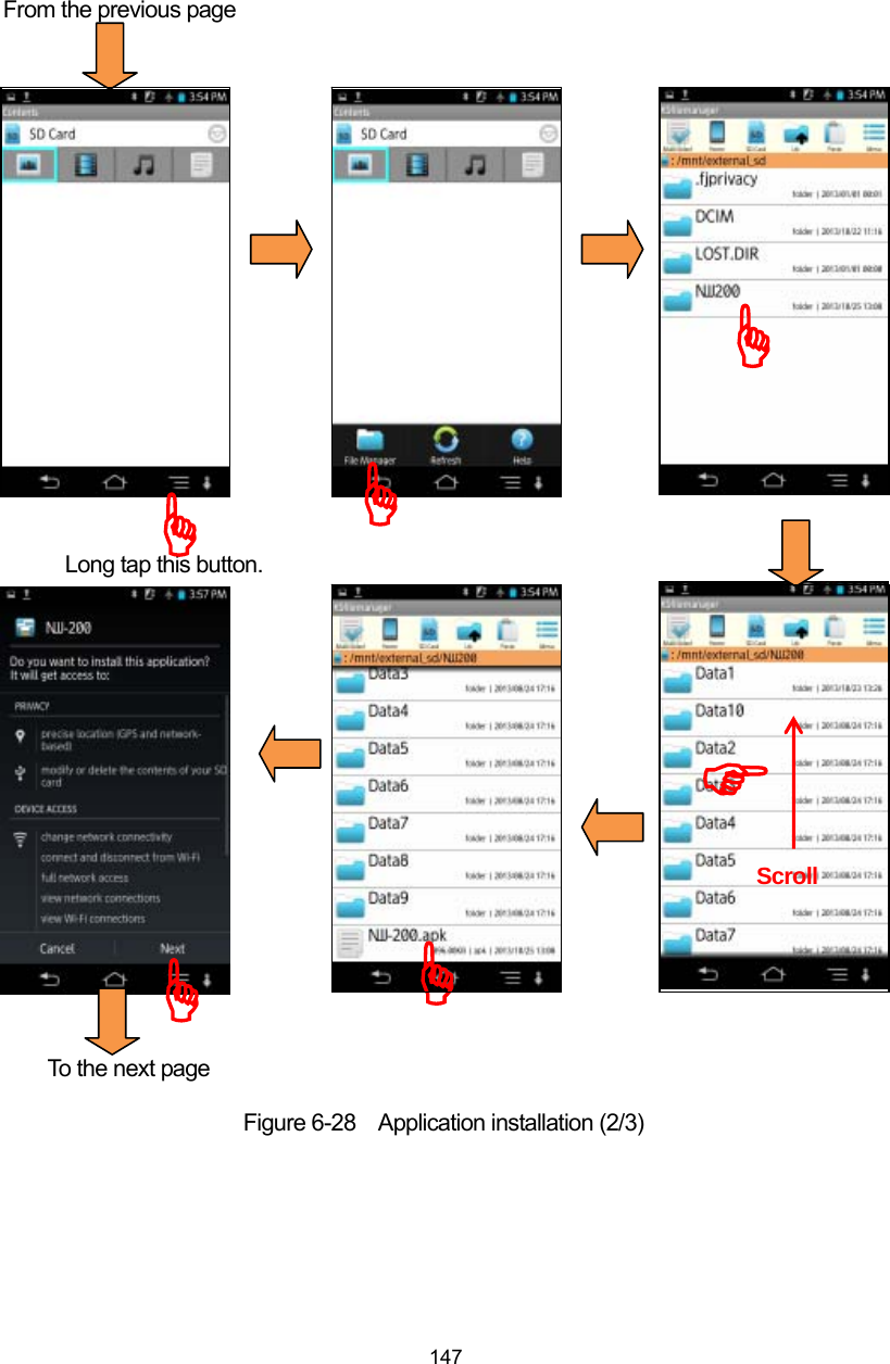
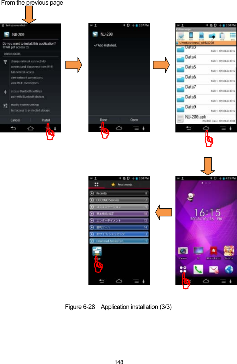
![146 (3) Install NJJ-200 application into Smartphone with the following procedure. a) At the security setting in Smartphone, set the setting so as to allow the installation of applications from the unknown sources. For the detailed procedure, refer to the manual attached to Smartphone. Example: Tap [Setting], [Device setting], [Lock & Security], and tap [Unknown source]. b) Activate the file management application (Contents manager, File commander, etc.) in Smartphone. Then install NJJ-200 application by tapping [NJJ-200] which was copied into the memory card of Smartphone. Make sure [NJJ-200] icon is registered in [Downloaded] at [Application] screen on Smartphone. If the icon is not registered, check if steps (1) and (2) above have been completed correctly To the next page Figure 6-28 Application installation (1/3) )))](https://usermanual.wiki/Japan-Radio/NJJ-200.Users-Manual-3/User-Guide-2182938-Page-27.png)
![149 6.9.2. Software version up for Sensor unit You can update the software inside the sensor unit by using NJJ-200 application through the wireless LAN. The procedure is provided below. (1) Copy the sensor unit’s new software file from PC to Smartphone by performing the following steps. By connecting Smartphone and a PC by using micro USB cable, Smartphone can be recognized and mounted as a removal data drive on the PC, then the file copy operation of drag and drop becomes available. By using this capability, copy NJJ-200 application file from the PC to Smartphone. In advance, prepare the sensor unit software file in the PC. a) On Smartphone, enable the file operation on Smartphone’s memory card from the PC by setting Smartphone into Card reader mode or File transfer mode (MSC). For the detailed procedure, refer to the manual attached to Smartphone. Example: Tap [Setting], [Device setting], [External Connection], [USB Connection], then [Card reader mode]. b) Connect Smartphone to a USB port of the PC by using a micro USB cable. c) On Smartphone, tap [Turn on USB Storage]. d) On the PC, Confirm that Smartphone’s data storage is recognized and mounted as a removal data drive on the PC. e) Create the folder “NJJ200” in Smartphone data drive mounted in steps above. f) Copy the sensor unit software file (File name: “NJJ-200_FIRM1.BIN/NJJ-200_FIRM2.BIN”) on the PC to the folder “NJJ200” on Smartphone by using Drag and Drop capability. If the file of the same name exists on the folder “NJJ-200” on Smartphone, copy the file at overwriting. g) Remove the drive of Smartphone from the PC by using the PC function of the safety drive removal. h) On Smartphone, tap [Turn off USB storage].](https://usermanual.wiki/Japan-Radio/NJJ-200.Users-Manual-3/User-Guide-2182938-Page-30.png)
![150 (2) Update the sensor unit software You can update the sensor unit software with the following procedure. a) Turn on the sensor unit and boot up NJJ-200 application on Smartphone, then establish the wireless LAN communication between the sensor unit and Smartphone. b) Log tap [Parameter] icon, then tap [Version] menu. Then the version management screen appears. Figure 6-29 Version management screen ))](https://usermanual.wiki/Japan-Radio/NJJ-200.Users-Manual-3/User-Guide-2182938-Page-31.png)
![151 c) Confirm the new software version, then update the version The version screen shows the current version of the sensor unit in the first message. (Figure 6-30 shows the example of the version “Ver1.0.0”.) Confirm that the version shown in the second message “You can update the sensor unit software to Ver1.02” is matched with the targeted version you want to update. If the version is not matched with the targeted version, confirm the software file prepared in Step (1) Tap [Update] menu, then a message “Updating the software. Wait a while.” appears. Then the software update is executed. After completing the software update, a message “The sensor software updates completed successfully.” [OK] Appears. Then tap [OK] to return to the parameter setup screen. After the software update, the sensor unit is automatically reset. (When the sensor unit is resetting, the wireless communication with Smartphone drops.) Figure 6-30 Sensor software update ))Confirm the version.](https://usermanual.wiki/Japan-Radio/NJJ-200.Users-Manual-3/User-Guide-2182938-Page-32.png)

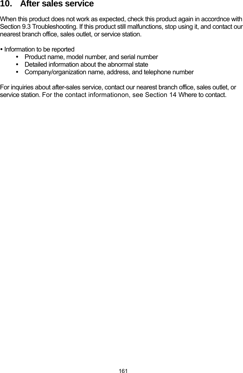
![159 9.3. Troubleshooting This product's behaviors listed below are not always a sign of trouble. Please re-check this product again before asking for repair. Table 9-1 Troubleshooting (1/2) Behavior Check items and recommended actions The sensor unit cannot be turned on. Power LED does not light. • Check if the battery pack is mounted. →Mount a fully charged battery pack in accordance with Section 2.6 Attachment of the battery pack. • Check if the battery pack is exhausted. →Mount a fully charged battery pack in accordance with Section 2.6 Attachment of the battery pack. The battery pack is exhausted rapidly. y Check if the battery pack is charged sufficiently. →Charge the battery pack fully in accordance with Section 7.2 Battery charger PPT20003 . • Has the battery pack itself reached the end of its life? → Replace it for a new battery pack that is fully charged. Wireless LAN communication between the sensor unit and Smartphone is not established. y Is Smartphone set to Airplane mode? →Set Smartphone to be in Airplane mode in accordance with Section 2.8 Communication setup. y Is the sensor unit selected correctly? →Select the used sensor unit in accordance with Section 4.11.19 Other: [Sensor select] menu. Wireless LAN communication between the sensor unit and Smartphone drops. y Is the other radio equipment operating nearby? →Change the channel in accordance with Section 4.11.18 Sensor setting: [Channel] menu. Smartphone does not beep at the start of scanning. y Is the sound of Smartphone turned off? →Turn the sound of Smartphone on in accordance with Section 4.11.9 Device setting: [Sound] menu. y Is Smartphone set in the manner mode? →Release the manner mode of Smartphone in accordance with the manual of Smartphone. The B-mode display moves forward when simply tapping [START] icon without moving the sensor. y Is the measurement method set to Time? →Set the measurement mode to be in Distance in accordance with Section 4.11.15 Sensor setting: [Measurement mode] menu.](https://usermanual.wiki/Japan-Radio/NJJ-200.Users-Manual-3/User-Guide-2182938-Page-40.png)
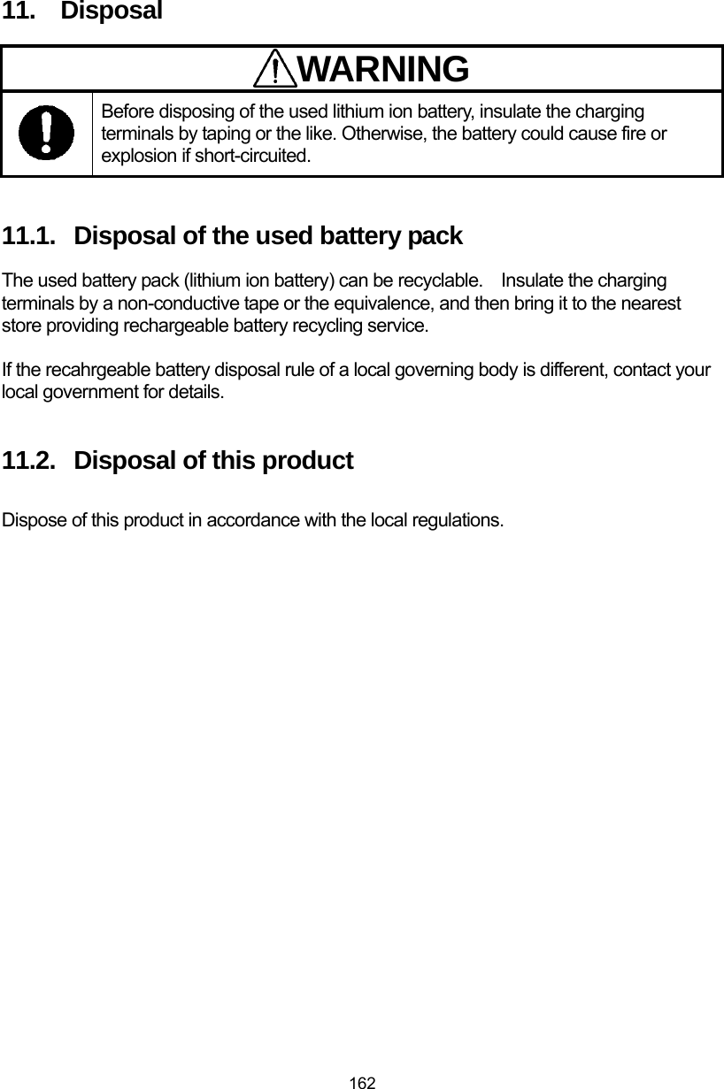
![160 Table 9-1 Troubleshooting (1/2) State Check items and recommended actions When doing any file operations, a message “No SD card” appears. y Is the SD card attached correctly into Smartphone? →Turn Smartphone off, and confirm the SD card attached correctly into Smartphone. y Is the memory card mounted correctly on Smartphone? →Mount the memory card in accordance with the manual of Smartphone. When tapping [File/Print] icon, any printer is not detected. y Is the printer setup completed correctly? →Perform the printer setup correctly in accordance with Section 5.8.1 Preparation for the printer. y Is the pairing of Smartphone and the printer completed correctly? →Execute the pairing in accordance with Section 5.8.2 Bluetooth pairing. When tapping [File/Print] icon, a message “Cycle the printer power” appears. y Is the printer initialized? →Cycle the power of the printer, then try again to print out by tapping [File/Print] icon. →Set up the printer correctly in accordance with the manual of the printer. When tapping [File/Print] icon, a message “Charge the printer battery.” Appears. y Check if the printer battery pack is exhausted. →Mount a fully charged battery pack, and tap [File/Print] icon again to start printing. When tapping [File/Print] icon, a message “No printing paper” appears. y Is the printer in out of paper? →Load a new paper roll, and tap [File/Print] icon again to start printing. When tapping [File/Print] icon, a message “Printer error” appears. y Check if the printer displays an error message. →Eliminate the cause of the printer error in accordance with the manual of the printer. Continuous use warms the casing. →This is a normal phenomenon.](https://usermanual.wiki/Japan-Radio/NJJ-200.Users-Manual-3/User-Guide-2182938-Page-41.png)