Japan Radio NKE1066 MARINE RADAR User Manual 5
Japan Radio Co Ltd. MARINE RADAR 5
Contents
- 1. User Manual 1
- 2. User Manual 2
- 3. User Manual 3
- 4. User Manual 4
- 5. User Manual 5
User Manual 5
Chapter
8
DETAIL PERFORMANCE SE
TTING
138
Chapter 9 MAINTENANCE AND CHECK
9-1 ROUTINE MAINTENANCE
For operating the radar equipment in the good conditions, it is necessary to make the maintenance
work as described below. If maintenance is made properly, troubles will reduce.
It is recommended to make regular maintenance work.
Common points of maintenance for each unit are as follow:
Clean the equipment.
Remove the dust, dirt, and sea water rest on the equipment cabinet with a piece of dry cloth.
Especially, clean the air vents with a brush for good ventilation.
Chapter 9 MAINTENANCE AND CHECK
139
9-2 MAINTENANCE OF EACH UNIT
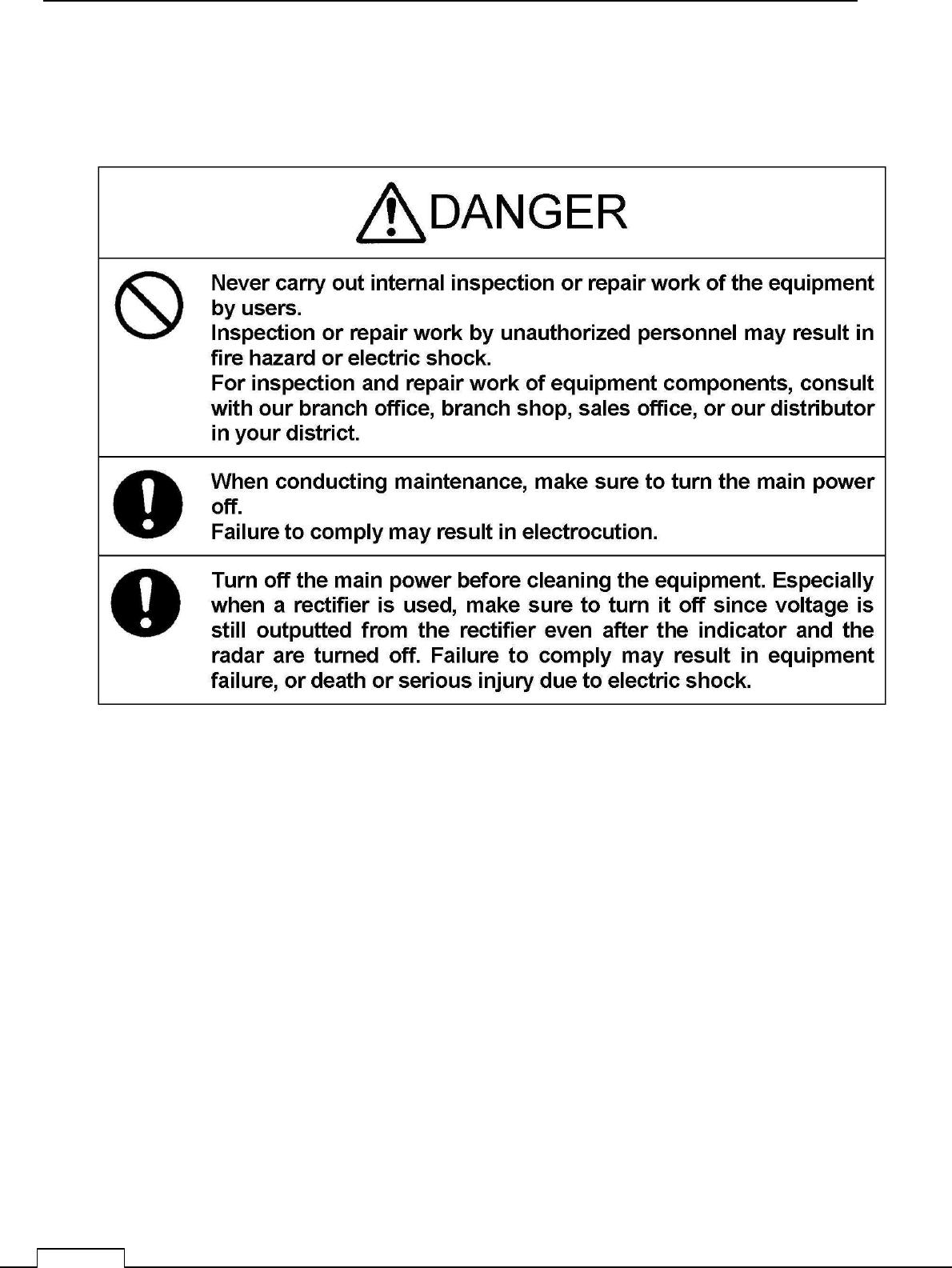
9-2-1 SCANNER NKE-1066
When conducting maintenance work on the antenna, make
sure to turn its main power off.
Failure to comply may result in electrocution or injuries.
DAN
G
ER
Chapter
9
MAINTENANCE AND CHECK
140
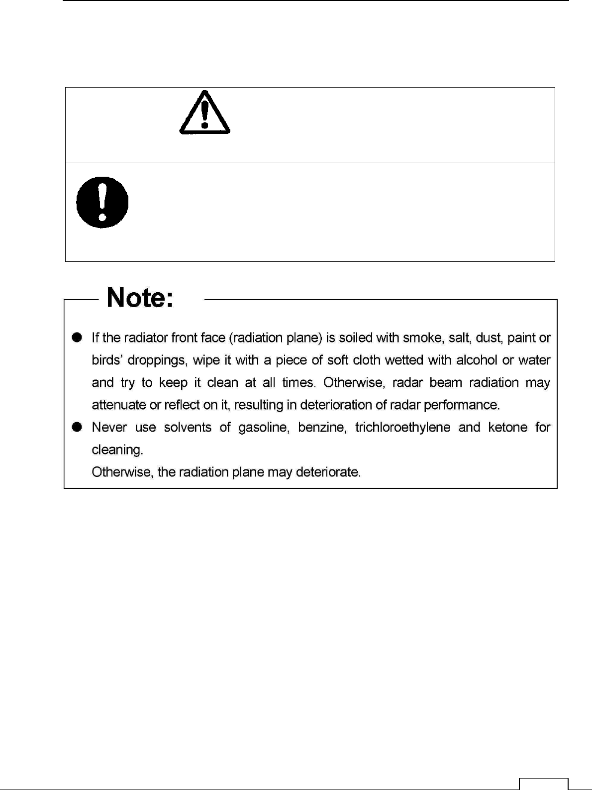
9-2-2 SCANNER NKE-2044
When conducting maintenance work on the antenna, make sure to
turn its main power off.
Failure to comply may result in electrocution or injuries.
DAN
G
ER
Chapter 9 MAINTENANCE AND CHECK
141
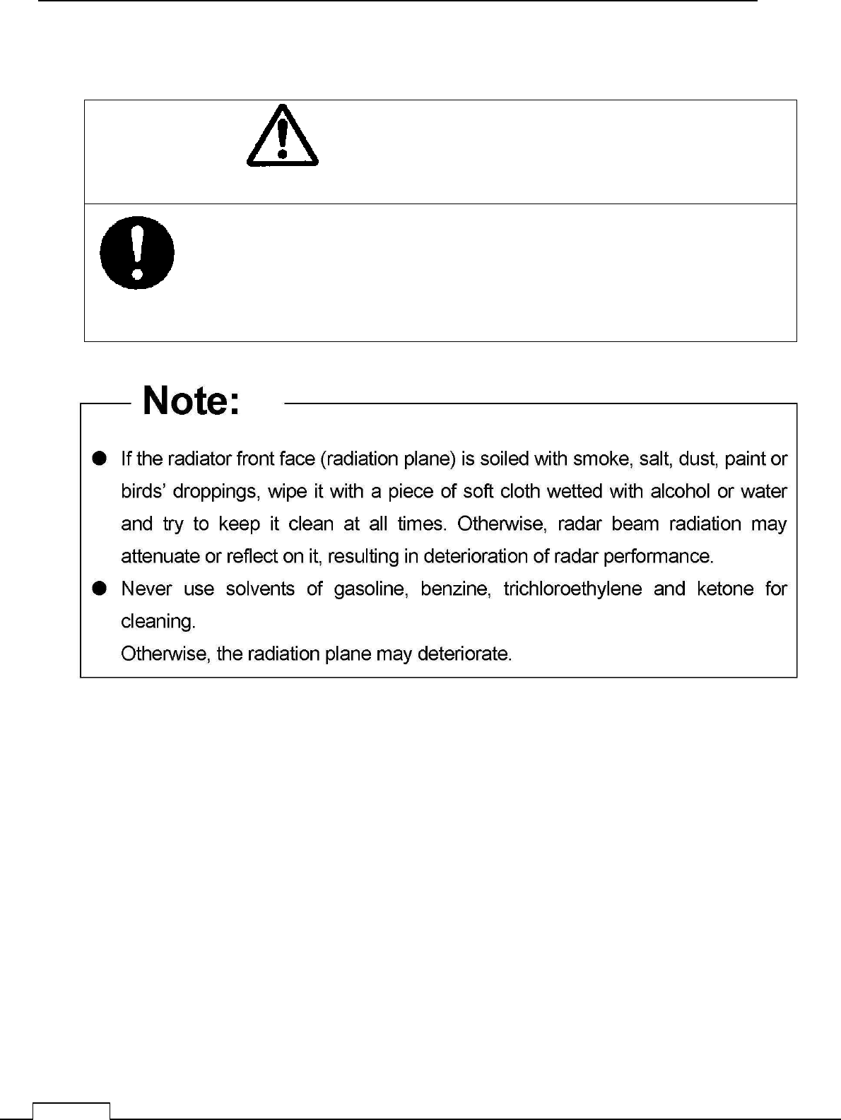
9-2-3 DISPLAY NCD-2256
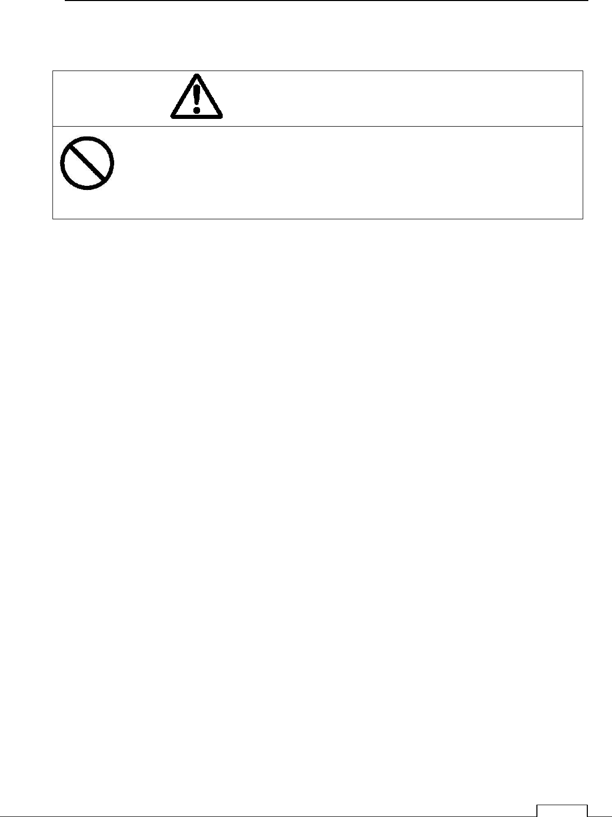
When cleaning the display screen, do not wipe it too strongly with
a dry cloth. Also, do not use gasoline or thinner to clean the screen.
Failure to comply will result in damage to the screen surface
.
Dust accumulated on the screen will reduce clarity and darken the video.
For cleaning it, wipe it with a piece of soft cloth (flannel or cotton).
Do not wipe it strongly with a piece of dry cloth nor use gasoline or thinner.
DAN
G
ER
Chapter
9
MAINTENANCE AND CHECK
142
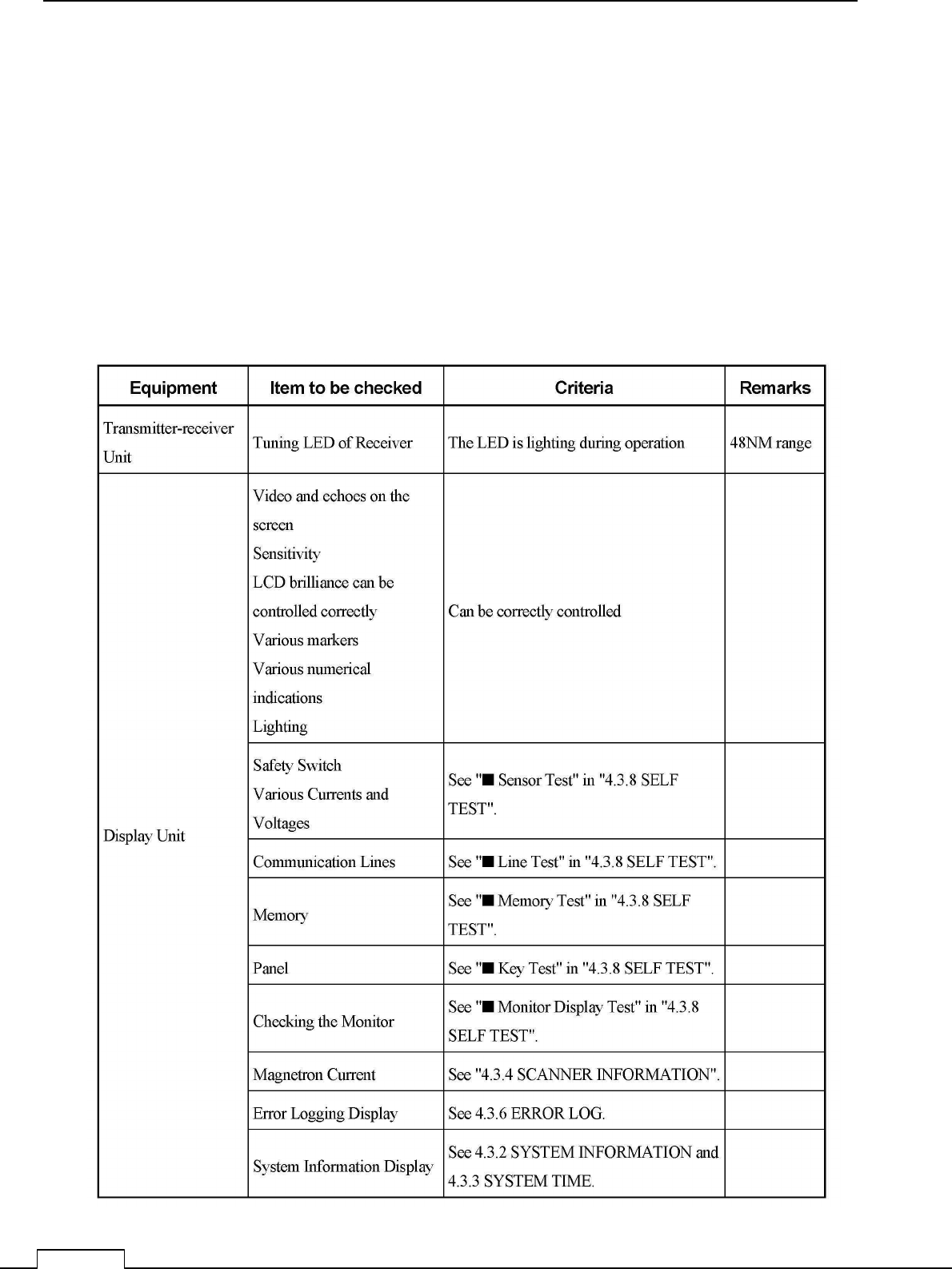
9-3 PERFORMANCE CHECK
Make operational check on the radar equipment regularly and if any problem is found,
investigate it immediately.
Pay special attention to the high voltage sections in checking and take full care that no
trouble is caused by any error or carelessness in measurement. Take note of the results of
checking, which can be used effectively in the next check work.
Operational check shall be made in accordance with Table 4.3-1 Function Check List in
the order as specified in it.
Table 9-3-1 Performance Check List
Chapter 9 MAINTENANCE AND CHECK
143
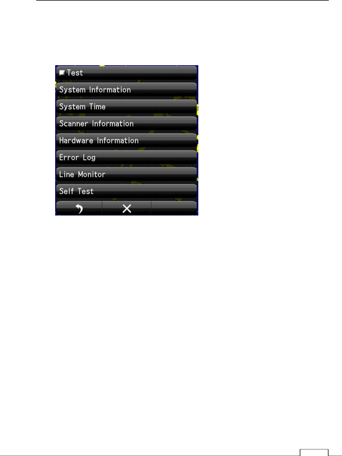
9-3-1 TEST MENU
The performance status of this radar equipment can be checked on the Test Menu.
9-3-2 SYSTEM INFORMATION
Displays the current system information. (software version information).
9-3-3 SYSTEM TIME
Displays the following system time information.
■ Indicator Running Time
■ Scanner Transmit Time
■ Scanner Motor Time
■ Scanner Running Time

Chapter
9
MAINTENANCE AND CHECK
144
9-3-4 SCANNER INFORMATION
Displays the following scanner information.
■ Transmitted output power
■ Motor Type
■ Magnetron Current
9-3-5 HARDWARE INFORMATION
Displays the following hardware information.
■ Serial Number
■ MAC Address
■ Temperature
9-3-6 ERROR LOG
The error log displays previously occurred system alarms with the dates and times when
they occurred.
9-3-7 LINE MONITOR
Serial communication data can be seen on the built-in Line monitor.
Line monitor can be used to make sure that the serial data are received properly
Chapter 9 MAINTENANCE AND CHECK
145
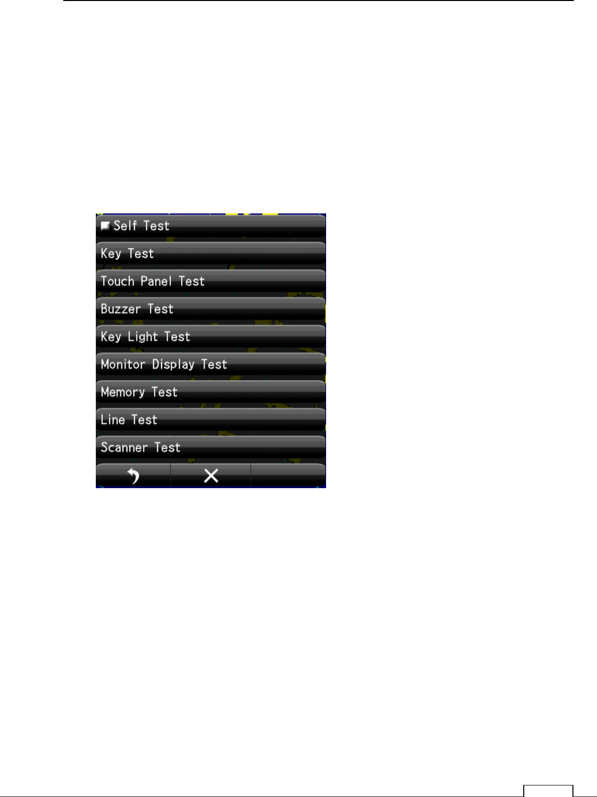
9-3-8 SELF TEST
The following tests can be performed.
■ Key Test
■ Buzzer Test
■ Key Light Test
■ Monitor Display Test
■ Memory Test
■ Line Test
■ Sensor Test

Chapter
9
MAINTENANCE AND CHECK
146
Chapter 9 MAINTENANCE AND CHECK
147
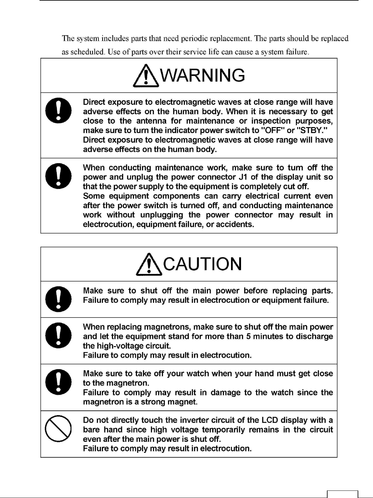
9-4 REPLACEMENT OF MAJOR PARTS

Chapter
9
MAINTENANCE AND CHECK
148
9-4-1 PARTS REQUIRED FOR PERIODIC REPLACEMENT
Here are parts required for periodic replacement.
PARTS NAME INTERVAL
1. MAGNETRON 4,000 HOURS
2. MOTOR 10,000 HOURS

Chapter 9 MAINTENANCE AND CHECK
149
9-5 FAULT FINDING
9-5-1 ALARMS AND OTHER DISPLAY LISTS
9-5-2 FUSE
9-6 TROUBLE SHOOTING
9-6-1 INCLUDED ACCESSORIES
9-6-2 SPECIAL PARTS
Location Parts No. Name Type Code Manufacture
NKE-1066 V101 Magnetron M1624 New JRC
NKE-2044 V101 Magnetron MSF1421B 5VMAA00092 New JRC
NKE-2044 A101 Circulator FCX68R 5AJIX00027 Orient Microwave
NKE-2044 A102 Diode Limiter NJS6930 5ATBT00006 New JRC
Chapter
9
MAINTENANCE AND CHECK
150
9-6-3 CIRCUIT BLOCK TO BE REPAIRED
JMA-1032
Location Circuit Block Type Remarks
Scanner Motor unit H-7BDRD0053
Scanner Modulation circuit CME-396 Include IF Amplifier
Scanner Micro wave unit
Transmitter/ receiver CMN-924/NZT-1066 Include Receiver
frontend
Display Unit Power Supply circuit
CBD-1928
Display Unit Process Circuit CDC-1433
Display Unit LCD Panel NZP-2256
JMA-1034
Location Circuit Block Type Remarks
Scanner Motor unit H7BDRD0052A
Scanner Modulation circuit CME-397 NZT-2044
Scanner Receiver NRG-242
Display Unit Power Supply circuit
CBD-1928
Display Unit Process Circuit CDC-1433
Display Unit LCD Panel NZP-2256

Chapter 9 MAINTENANCE AND CHECK
151

Chapter 10 AFTER
-
SALE SERVICE
152
Chapter 10 AFTER-SALE SERVICE
10-1 KEEPING PERIOD OF MAINTENANCE PARTS
Keeping period of maintenance parts is ten years from the production is discontinued.
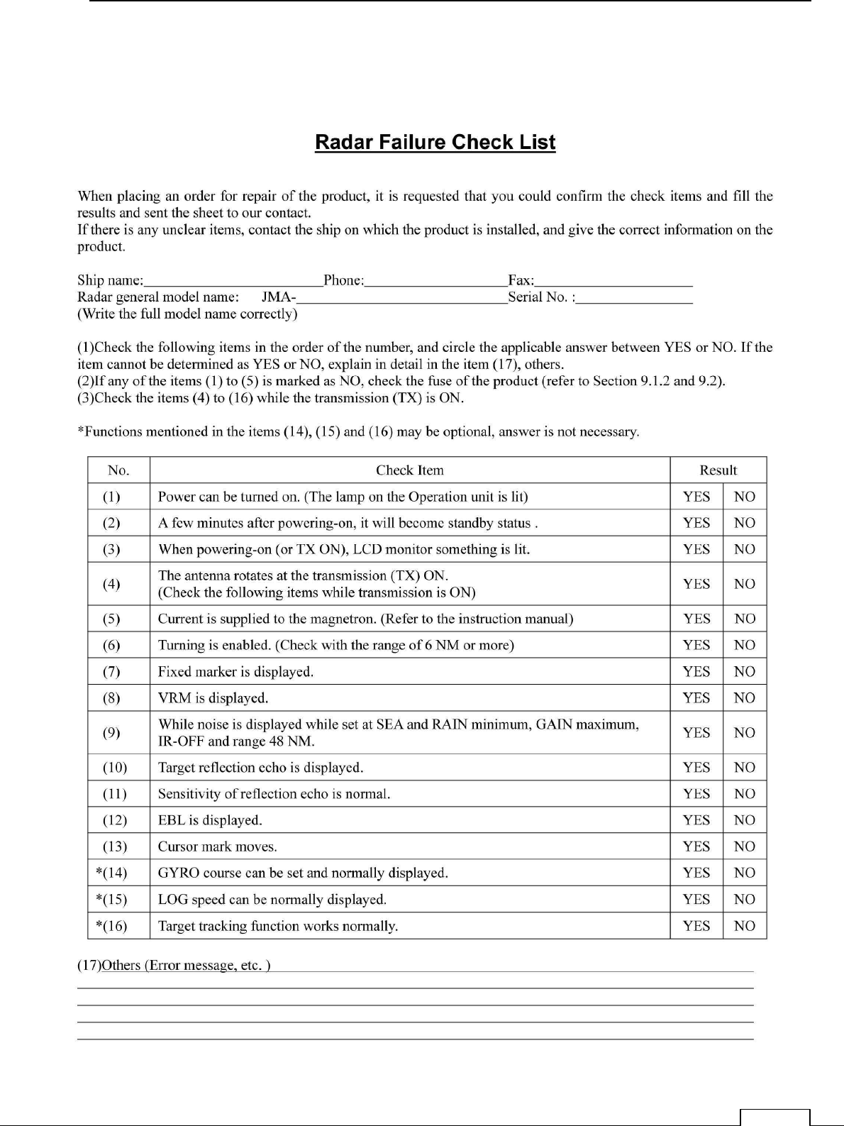
10-2 WHEN YOU REQUEST FOR REPAIR
If you suppose the product may be out of order, read the description in "9-2-5 FAULT
FINDING" and "9-2-6 TROUBLE SHOOTING", and check the suspected point again.
If it is still out of order, you are recommended to stop operation of the equipment and
consult with the dealer from whom you purchased the product, or our branch office in
your country or district, the sales department in our main office in Tokyo.
● Repair within the Warranty Period
If any failure occurs in the product during its normal operation in accordance with the instruction
manual, the dealer or JRC will repair free of charge.
In case that any failure is caused due to misuse, faulty operation, negligence or force major
such as natural disaster and fire, the product will be repaired with charges.
● Repair after the Warranty Period.
If any defective function of the product is recoverable by repair, the repair of it will be made at
your own charge upon your request.
● Necessary Information for Repair
Product name, model, manufacturing date and serial number
Trouble conditions (as detailed as possible. Refer to page "
10-4 Radar failure check list
".)
Name of company/organization, address and telephone number
10-3 RECOMMENDED MAINTENANCE
The performance of the product may deteriorate due to the secular change of the parts used in it,
though such deterioration depends upon the conditions of operation.
So checkup and maintenance is recommendable for the product in addition to your daily care.
For maintenance, consult with the near-by dealer or our sales department.
Such maintenance will be made with charges.
For further details of after-sale service, contact the JRC Offices.
Chapter 10 AFTER
-
SALE SERVICE
153
10-4 RADAR FAILURE CHECK LIST

Chapter 11 DISPOSAL
154
Chapter 11 DISPOSAL
11-1 DISPOSAL OF THE UNIT
When disposing of this unit, be sure to follow the local laws and regulations for the place of
disposal.
Chapter 11 DISPOSAL
155
11-2 DISPOSAL OF USED MAGNETRON
A magnetron is used for the scanner (NKE-1066) (NKE-2044).
☆ When the magnetron is replaced with a new one, return the used magnetron to our
dealer or business office.
For detail, consult with our dealer or business office.
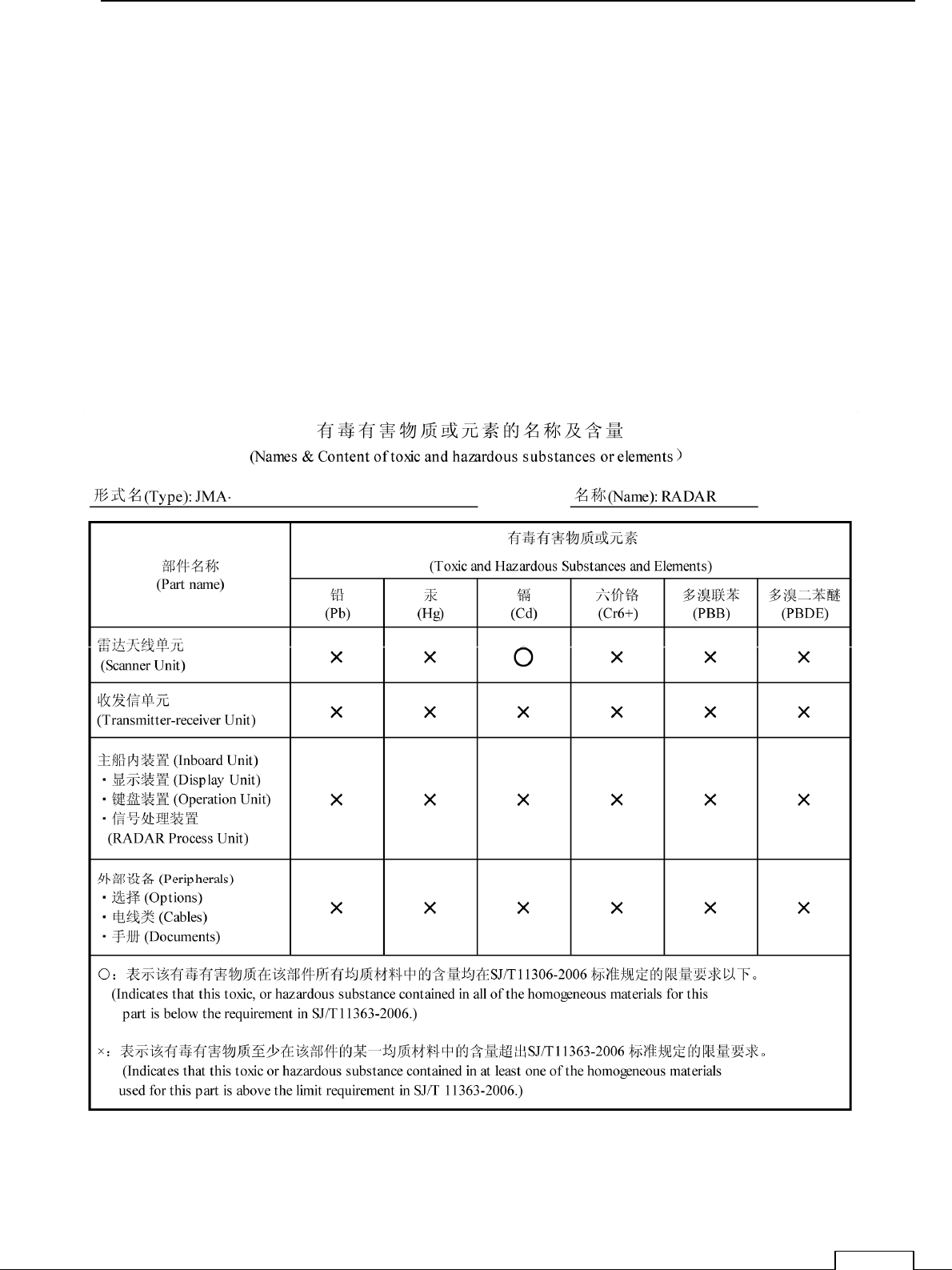
11-3 CHINA ROHS

Chapter 11 DISPOSAL
156
Chapter 12 SPECIFICATIONS
158
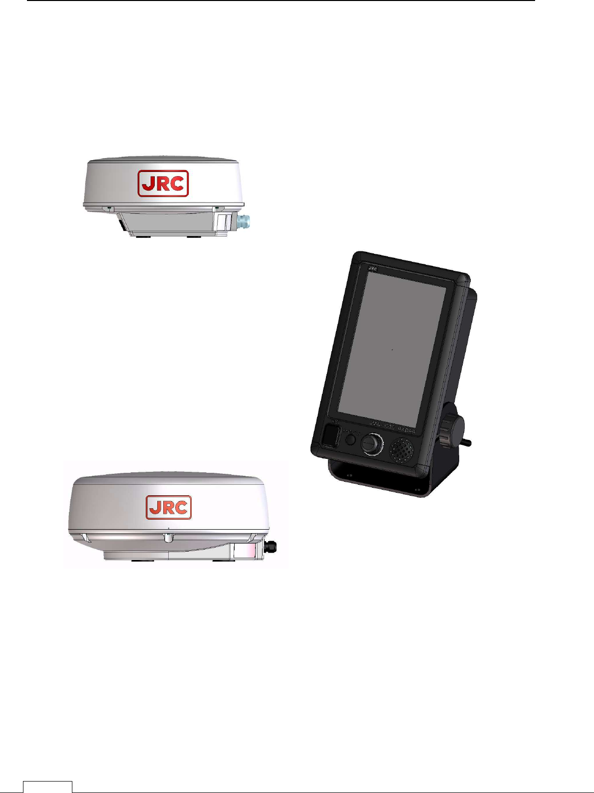
NCD-2256 display
NKE-2044 scanner
2ft Scanner
4kw
Radome diameter
φ
620mm
Display 7inches wide LCD
NKE-1066 scanner
Chapter 12 SPECIFICATIONS
1.5ft scanner 4kw
Radome diameter
φ
450mm
Chapter 12 SPECIFICATIONS
159
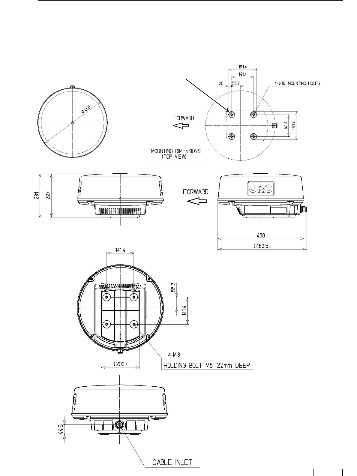
12-1 SCANNER DIMENSION
12-1-1 NKE-1066
NKE-1066
1.5ft scanner 4kw radome φ450mm
4-φ40 RUBBER PLATE
Chapter 12 SPECIFICATIONS
160
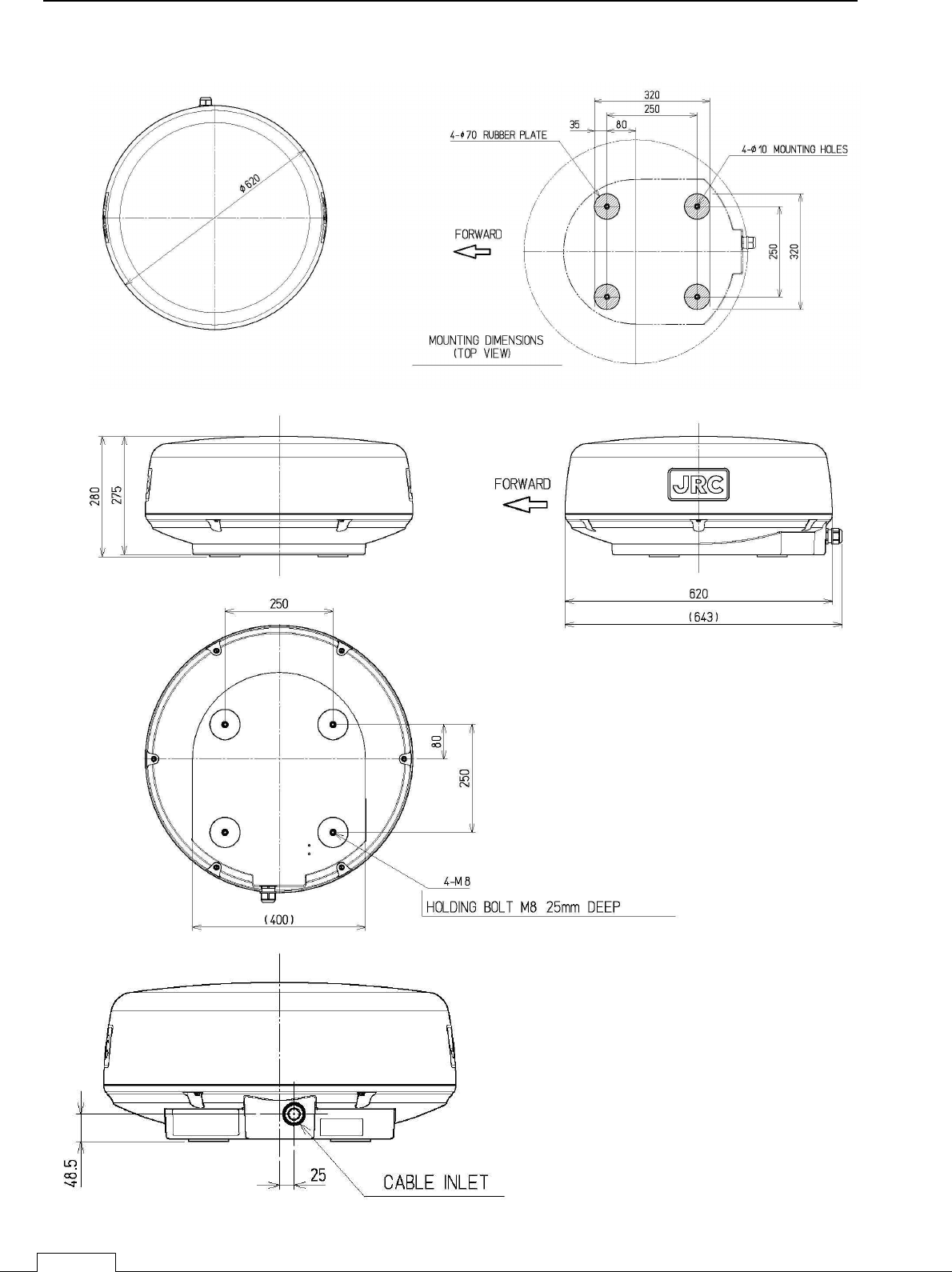
12-1-2 NKE-2044
Chapter 12 SPECIFICATIONS
161
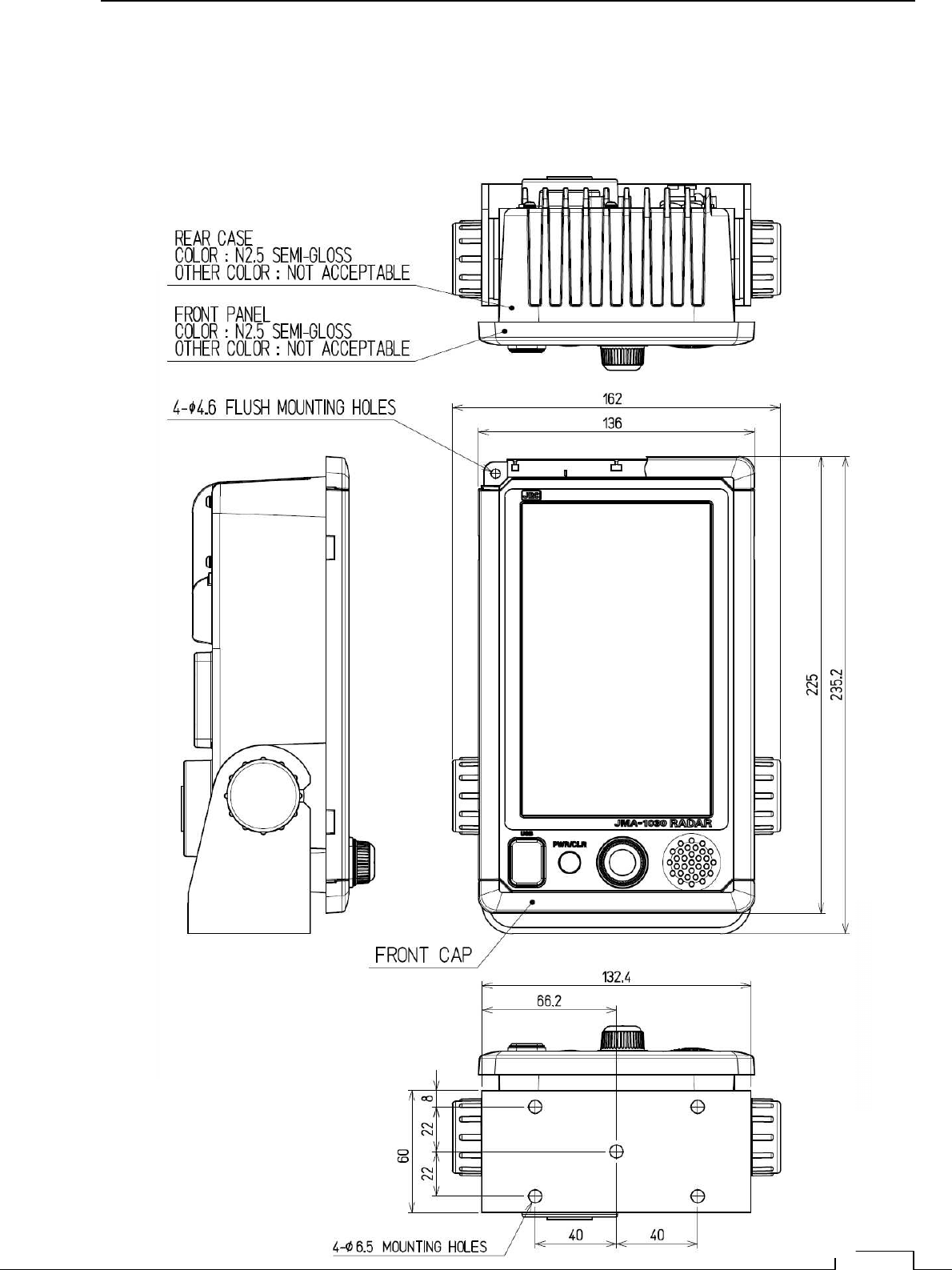
12-2 DISPLAY DIMENSION
12-2-1 NCD-2256
Chapter 12 SPECIFICATIONS
162

Chapter 12 SPECIFICATIONS
163
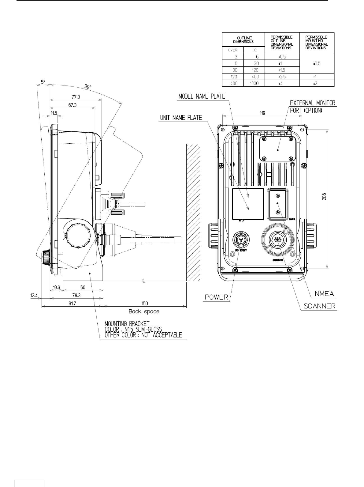
12-3 EQUIPMENT OUTLINE
1)This equipment is a marine radar for vessels and work boats which consists of the display
unit including 7 inch wide VGA color LCD Monitor unit, Keyboard unit, Processing unit and
consists of the 1.5 ft /2ft radome type scanner unit. The processing unit uses SOC (LUPIM)
developed by JRC and the LCD monitor unit uses panel with touch sensor (resistance film type).
The operation can be realized intuitive and simple.
12-3-1 CONFIGULATION
1) Display unit NCD-2256
・ Integrated the 7 inch wide VGA color LCD Monitor unit, Keyboard unit and Processing unit
2) Scanner unit
・ X-band 1.5ft(4kW) radome type is NKE-1066
・ X-band 2ft(4kW) radome type is NKE-2044
12-3-2 FEATURE
1) The screen resolution is 800x480dots (WVGA).
The LCD monitor unit with touch sensor (resistance film type).
2) Highly efficient signal processing using the SOC including DSP.
3) TT and AIS function are prepared by SOC using.
12-3-3 RADAR MODEL
JMA-1032 1.5ft Scanner unit
JMA-1034 2.ft Scanner unit
12-3-1 CONFIGURATION
Chapter 12 SPECIFICATIONS
164
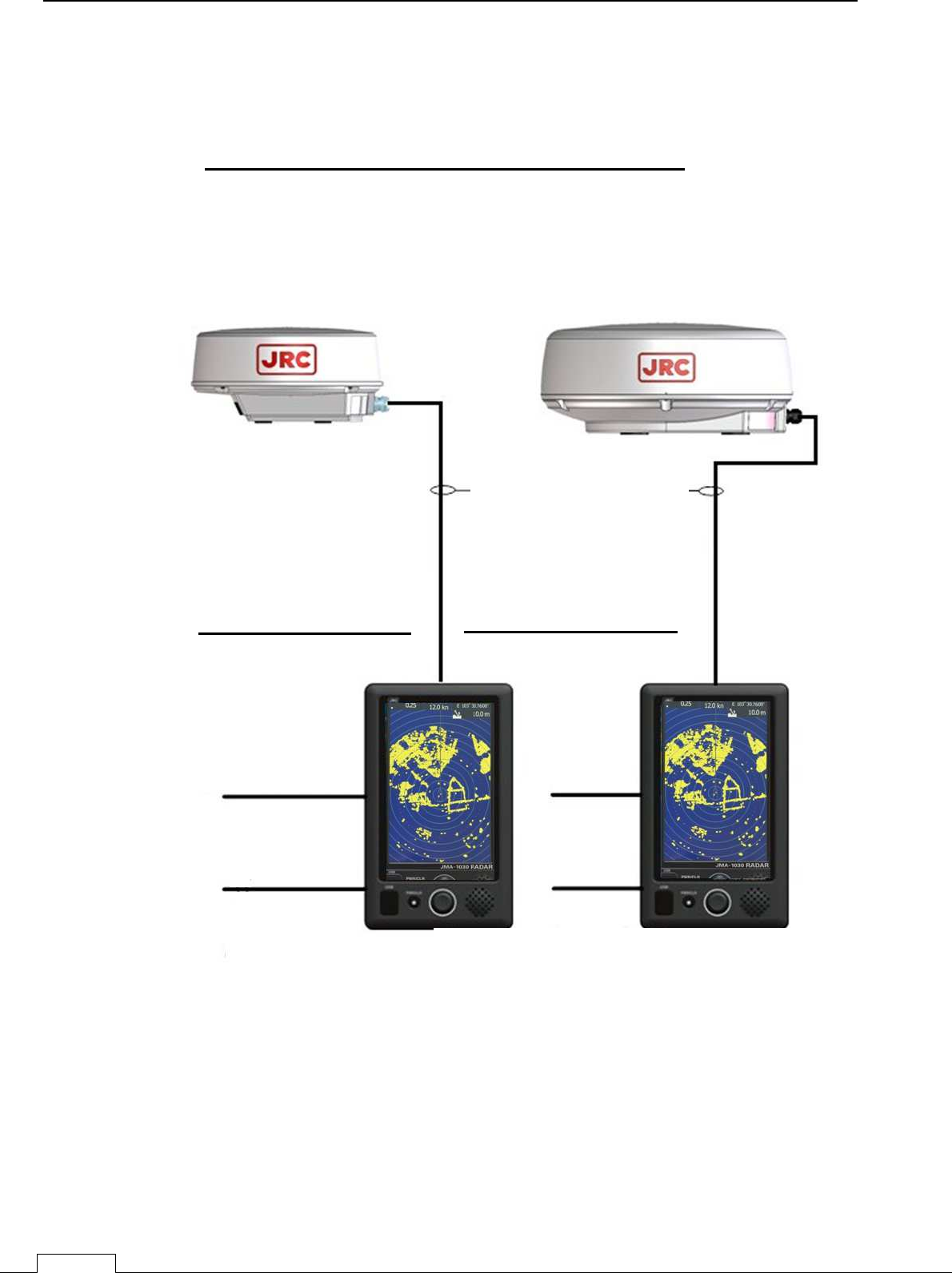
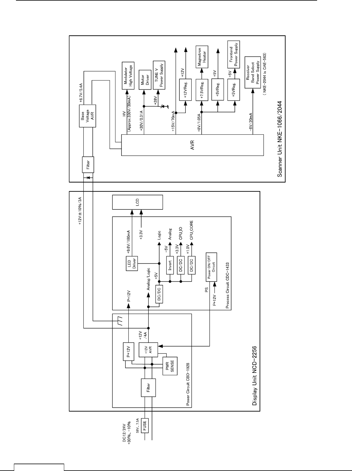
12-3-4 SYSTEM DIAGRAM
JMA
-
1030 Series system diagram
1.5feet Scanner Unit
(NKE-1066)
Radome diameter 450mm
2feet Scanner Unit
(NKE-2044)
Radome diameter 620mm
*
STANDARD LENGTH 10m
OPTION:
(cablelength:5m/15m/20m/30)
JMA
-
1034 RADAR
JMA-1032 RADAR
7inch WIDE VGA COLOUR LCD DISPLAY
(NCD-2256)
CFQ9924-5,10,15,20,300
External Navigation
al
Signal input.
NMEA 3 input ports
(GPS,AIS,DEPTH)
CFQ-9900
Ship’s Main Power
(cable length 2m)
*INCLUDING FUSE IN PLUS LINE
FUSE TYPE: 7.5A/58V
(10.8-31.2VDC)

Chapter 12 SPECIFICATIONS
165
12-4 GENERAL SPECIFICATIONS
(1) Class of Emission P0N
(2) Display Color Raster Scan
(3)Display capability WVGA (800x480dots) Screen
(4) Screen 7-inch Color LCD with touch sensor (resistance film type)
(5) Range Scale 0.0625, 0.125, 0.25, 0.5, 0.75, 1.5, 3, 6, 12, 24, 48NM
(48 NM: only 2feet type scanner is available)
User can add 1, 2, 4, 8, 16, and 32NM
(32 NM: only 2feet type scanner is available)
(6) Range Resolution Less than 30m
(7) Minimum Detective Range Less than 40m
(8) Range Accuracy Less than 1% of the maximum distance of the range scale
in use or less than 15m whichever is greater.
(9) Bearing Accuracy Less than ±1°
(10) Bearing Indication RM: Head-up, North-up, Course-up
TM: North-up, Course-up
(11) Ambient Condition
Standards IEC60945 Ed.4.0
Temperature
Scanner Operation: -25 to +55°C / Storage: -25 to +70°C
Other Unit except Scanner Operation: -15 to +55°C / Storage: -15 to +70°C
Relative Humidity +40°C, 93%
Vibration 2 to 13.2 Hz, amplitude±1mm
13.2 to 100 Hz 0.7 G
Velocity of the wind 100kn
Waterproof/dustproof Scanner IP26
Display unit IP55
(12) Power Supply Input DC 10.8-31.2V (DC12-24V-10%+30%)
(13) Power Consumption Approx. 50W (NKE-1066/NKE-2044).
Maximum: 50W (NKE-1066: SP1, NKE-2044: LP2
transmitting)
(14) Pre heat time Approx. within 1min30sec.
(15) Display unit Refer to Display unit Specifications
(16)Inter-unit Cables Using common scanner connecting cable CFQ-9924-10
Standard Length 10m
Maximum cable length 30m

Chapter 12 SPECIFICATIONS
166
12-5 SCANNER
12-5-1 SCANNER (NKE-1066) SPECIFICATION
(1) Dimensions Height 231mm×Diameter of radome 450mm
(2) Mass Approx. 5.5kg
(3) Polarization Horizontal (antenna length 1.5 feet)
(4) Antenna Directivity Horizontal Beam Width (-3dB) 5.2°
Vertical Beam Width (-3dB) 25°
Side lobe Level Less than -21dB (less than ±10° from the main lobe)
(5) Rotation Approx. 27rpm (16/27/36/48rpm are available)
(6) Transmitting Frequency 9410±30MHz
(7) Peak Power 4 kW
(8)Transmitting Tube Magnetron [M1624]
(9) Pulse width/ Repetition Frequency (Bandwidth)
SP1: 0.08µs/4000 Hz (Wide 20MHz)
SP2: 0.08µs/2250 Hz (Wide 20MHz)
SP3: 0.13µs/1700 Hz (Wide 20MHz)
MP1: 0.25µs/1700 Hz (Middle 6MHz)
MP2: 0.5µs/1200 Hz (Narrow 3MHz)
LP1: 0.8µs/750 Hz (Narrow3 MHz)
(S: Short pulse, M: Middle pulse, L: Long pulse)
(10) Range Information 0.0625NM SP1
0.125NM SP1
0.25 NM SP1
0.5 NM SP1 / MP1
0.75 NM SP2 / MP1
1.5 NM SP2 / MP1 / MP2
3 NM SP3 / MP1 / MP2
6 NM MP2 / LP1
12 NM MP2 / LP1
24 NM LP1
(11) Duplexer Circulator + Diode Limiter
(Diode Limiter is included in the frontend)
(12) Front End Module MIC
(13) IF Frequency 60MHz
(14) IF AMP Log Amplifier (Gain: more than 90dB)
(15) Overall Noise Figure 6dB(Average)
(16) Tuning Manual/Auto

Chapter 12 SPECIFICATIONS
167
12-5-2 SCANNER (NKE-2044) SPECIFICATION
(1) Dimensions Height 280mm×Diameter of radome 620mm
(2) Mass Approx. 10.5kg
(3) Polarization Horizontal (antenna length 2 feet)
(4) Directional Characteristic Horizontal Beam Width (-3dB) 4°
Vertical Beam Width (-3dB) 25°
Side lobe Level -21dB or less (less than ±10° from the main lobe)
(5) Rotation Approx. 27rpm (16/27/36/48rpm are available)
(6) Transmitting Frequency 9410±30MHz
(7) Peak Power 4 kW
(8)Transmitting Tube Magnetron [MSF1421B]
(9) Pulse width/ Repetition Frequency (Bandwidth)
SP1: 0.08µs/4000 Hz (Wide 20MHz)
SP2: 0.08µs/2250 Hz (Wide 20MHz)
SP3: 0.13µs/1700 Hz (Wide 20MHz)
MP1: 0.25µs/1700 Hz (Middle 6MHz)
MP2: 0.5µs/1200 Hz (Narrow 3MHz)
LP1: 0.8µs/750 Hz (Narrow3 MHz)
LP2:1.0us/650Hz (Narrow:3MHZ)
(S: Short pulse, M: Middle pulse, L: Long pulse)
(10) Range Information 0.0625NM SP1
0.125NM SP1
0.25 NM SP1
0.5 NM SP1 / MP1
0.75 NM SP2 / MP1
1.5 NM SP2 / MP1 / MP2
3 NM SP3 / MP1 / MP2
6 NM MP2 / LP1/ LP2
12 NM MP2 / LP1/ LP2
24 NM LP2
48 NM LP2
(11) Duplexer Circulator + Diode Limiter
(12) Front End Module MIC
(13) IF Frequency 60MHz
(14) IF AMP Log Amplifier (Gain: more than 90dB)
(15) Overall Noise Figure 6dB(Average)
(16) Tuning Manual/Auto

Chapter 12 SPECIFICATIONS
168
12-6 DISPLAY
12-6-1 INTEGRATED DISPLAY UNIT (NCD-2256)
1) Structure Desk Top Integrated Type
(LCD Monitor Unit/Keyboard Unit/Processor Unit Integrated Structure)
Vertical installation only desk top integrated type
Option: Overhead Mounted kit installation
2) Dimensions Height 235.2mm × Width 162mm × Depth 77.3mm
(The U style mount base and the both sides knob bolts are
included.)
3) Mass Approx. 1.8kg
4) Tune Method Manual / Auto
(Bar-graph indication is displayed at the time of adjustment.)
5) STC (SEA) Manual / Auto
6) FTC (RAIN) Manual / Auto
7) Radar Interference Rejection Built-in (The effect can be adjusted by three stages.)
8) Bearing Marker 360° in 5° digit
9) Heading Line Electronic
10) Off Center move to the defined coordinates of 4 patterns
(4 patterns are back side 64dots,left side 92dots, front side
92dots, right side 92dots from the default center position)
Transition of the radar trails is possible during Off Center mode.
11) True Motion Unit Built-in (Not available at the maximum range)
12) True Motion Reset Position 40% of radius of any range
13) Radar trail indication True motion mode: Only true motion trails
Relative motion mode: Only relative motion trails
Trail time length: 15 sec to 15 min/Continuous
30 sec to 30 min/Continuous
1 min to 1 hr/Continuous
30 min to 12 hr/Continuous
Arbitrary trail time length can be displayed at any time.
Possible to display time series trail and continuous trail
by color classification.
* When switching to true/relative trails, the radar trails
are cleared. Transition of the trails is possible during Off
Center mode (Relative motion). (Scroll)
When the bearing mode is switched (RM (T), TM), the
radar trails are taken over at between RM (T) and TM.

Chapter 12 SPECIFICATIONS
169
14) Variety of Pulse width SP1/ SP2/ SP3/ MP1/ MP2/ LP1/ LP2
(LP2 is JMA-1034 only)
15) Target enhance 3 stages
16) Plotting 3 marks
17) Display color
Radar echo 16 stages, 8 colors (Yellow, Green, Blue, White, Magenta, Gold,
Amber, Color)
Radar trails 1 stage,
Time trails: 3 colors (Green, Blue, Cyan)
Continuous trails: 3 colors (Green, Blue, Cyan)
Background PPI: 3 colors (Black, Blue, White)
Characters 7 colors (White, Cyan, Green, Black, Red, Gold, Amber)
AIS/TT 3 colors (Cyan, Green, White)
EBL/VRM 4 colors (Cyan, Black, Magenta, White)
Cursor 4 colors (White, Red, Magenta, Yellow)
Own Ship's 6 colors (Cyan, Green, Red, White, Gold, Amber)
Range Ring 6 colors (Cyan, Green, Red, White, Gold, Amber)
Alarm Zone 5 colors (White, Green, Orange, Black, Red)
18) Simulator Built-in
19) Multiple languages English, Spanish, Turkish, Indonesian, Thai, Malay, Vietnamese,
Chinese, Russian, Korean, Japanese, Other optional language
20) Range Unit NM, Km, sm
21) Navigation information during STBY Built-in
22) AIS information display (MMSI, ship name) List display, WPT setting,
Can display ship name only

Chapter 12 SPECIFICATIONS
170
12-6-2 OPERATIONAL PANEL
1) Structure Integrated on the display unit
2) Key
PWR/CLR Short push: Power ON ( at the time of Power OFF)
Long push: Power OFF
PWR/CLR Short push: input cancel, back to a up-layer
3) K
nob Controller PUSH : Menu or Icon selection and
execution
, control
EBL/VRM, number input, Enter, etc.
PUSH + rotation: Brilliance control
4) Touch
control Tap: Menu or Icon selection and
execution
, control, etc.
Double tap: Brilliance menu
Icon Double tap: EBL/VRM disappear
Icon Long tap: Entry of short cut Icon
12-6-3 AIS FUNCTION (STANDARD BUILT IN)
1) Display
Number of targets Up to 50 targets (stores up to 500 ship static data)
Target information Displays MMSI, call sign, ship name, COG, SOG, CPA, TCPA, direction,
distance, latitude, longitude, status, etc.
Filters Distance only
Active targets Not available
Dangerous ship targets No CPA/TCPA decision
2) Operation Built-in
12-6-4 TT FUNCTION (STANDARD BUILT IN)
1) Acquisition MANUAL/AUTO (by automatic acquisition/activation zone)
2) Tracking 10 targets (Automatic tracking)
3) Display
Tracking data 1 ship (AIS or TT)
Maximum tracking range 20NM (This varies depending on the range)
Target information Displays items selected from true bearing, distance,
true course, true speed, CPA, TCPA.
Display of Vectors True/Relative
4) Operation Built-in

Chapter 12 SPECIFICATIONS
171
12-7 INPUT/ OUTPUT SIGNAL
12-7-1 INPUT ENABLE SIGNAL
(Three-port input GPS/HDG/AIS)
(1) Navigation equipment IEC61162-1/2(※1)
L/L: GGA>RMC>RMA>GNS>GLL
SOG/COG: RMC>RMA>VTG
Log speed: VBW>VHW
HEADING: THS>HDT>HDG>HDM
DEPTH: DPT>DBT
WATER TEMP: MTW
ROT: ROT
RUDDER: RSA
AIS: VDM, VDO, ALR
WIND: MWV>VWT, VWR
WAYPOINT: WPL
(2) Bearing signal JRC-NSK format (JLR-10/20/30)(by NMEA3 port)
IEC61162-1/2(※1) 4800bps/38400bps: THS>HDT>HDG>HDM
(3) Speed signal IEC61162 4800bps: VBW, VHW
※1:IEC61162-2 Conformity is unnecessary.
(Insulation is unnecessary. Input electrical tests are unnecessary.)
Telecommunications standard NMEA0183 / 61162 -1/2
Communications protocol 4800 bps, start 1bit, data 8bit, stop 1bit,
non parity
Input sentence NMEA0183: V1,5: GGA/ GLL/ RMC
V2,0: GGA/G LL/ RMC/ZDA
V2,3 : GGA/GLL/RMC/GNS/ZDA
(Talker=”GP” etc.)
Information classification position and time GGA/G NS/G LL/RMC
date ZDA/RMC
Time ZDA/GGA/GNS/GLL/RMC

Chapter 12 SPECIFICATIONS
172
12-7-2 OUTPUT POSSIBLE SIGNAL (THREE-LINE GPS/HDG/TTM)
(1) Navigation equipment
Radar date: RSD
Own ship’s data: OSD
TT data: TTM, TTL, TTD
Latitude/ Longitude data: GGA, RMC, GNS, GLL,
COG/SOG: VTG (Received GPS data)
Bearing signal: THS, HDT (Received GPS Compass data)
(2) External Buzzer Factory presetting: normal open contacts
(3) Output RGB signal To incorporate optional kit (NQA-2447) is necessary
※In this case, waterproofing (IPx5) of rear side of display unit is not guaranteed
(4) Slave display no function
(5) LAN no function
12-7-3 STANDARD CONFIGURATION
Scanner: 1unit
Display Unit: 1unit
Sun cover: 1unit
Scanner cable: 1pc. (10m)
Power cable: 1pc. (2m)
Standard included accessories: 1set (2 pieces. fuse)
Instruction /Installation/Quick manual: 1 book
12-7-4 OPTION CABLE
Scanner cable: 5m, 15m, 20m,30m
NMEA cable (waterproof (IPx5)): 1m
APPENDIX-1
Chapter 13 APPENDIX
Chapter 13 APPENDIX
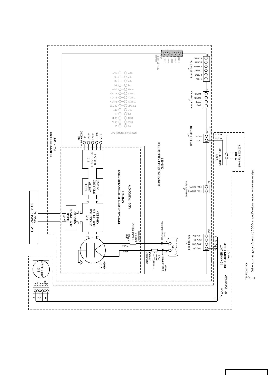
NKE-1066(1.5FT) SCANNER INTRCONNECTION DIAGRAM
FIG A1
APPENDIX-2
Chapter 13 APPENDIX
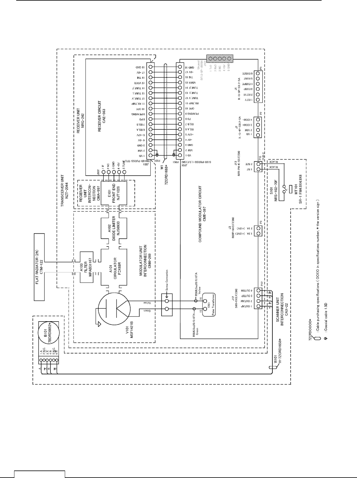
NKE-2044(2FT) SCANNER INTRCONNECTION DIAGRAM
FIG A2
APPENDIX-3
Chapter 13 APPENDIX
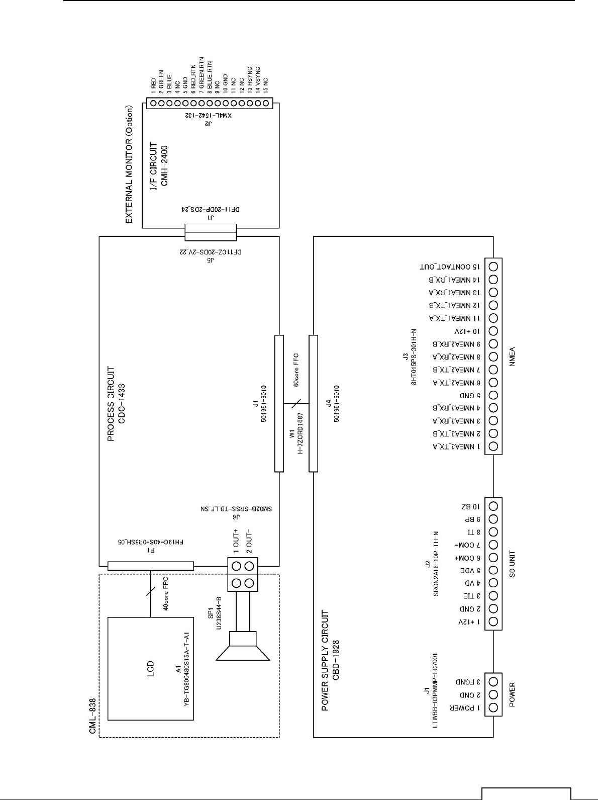
NCD-2256 DISPLAY UNIT INTER CONNECTION DIAGRAM
FIG A3
APPENDIX-4
Chapter 13 APPENDIX
JMA-1030 PRIMARY POWER SUPPLY DIAGRAM
FIG A4
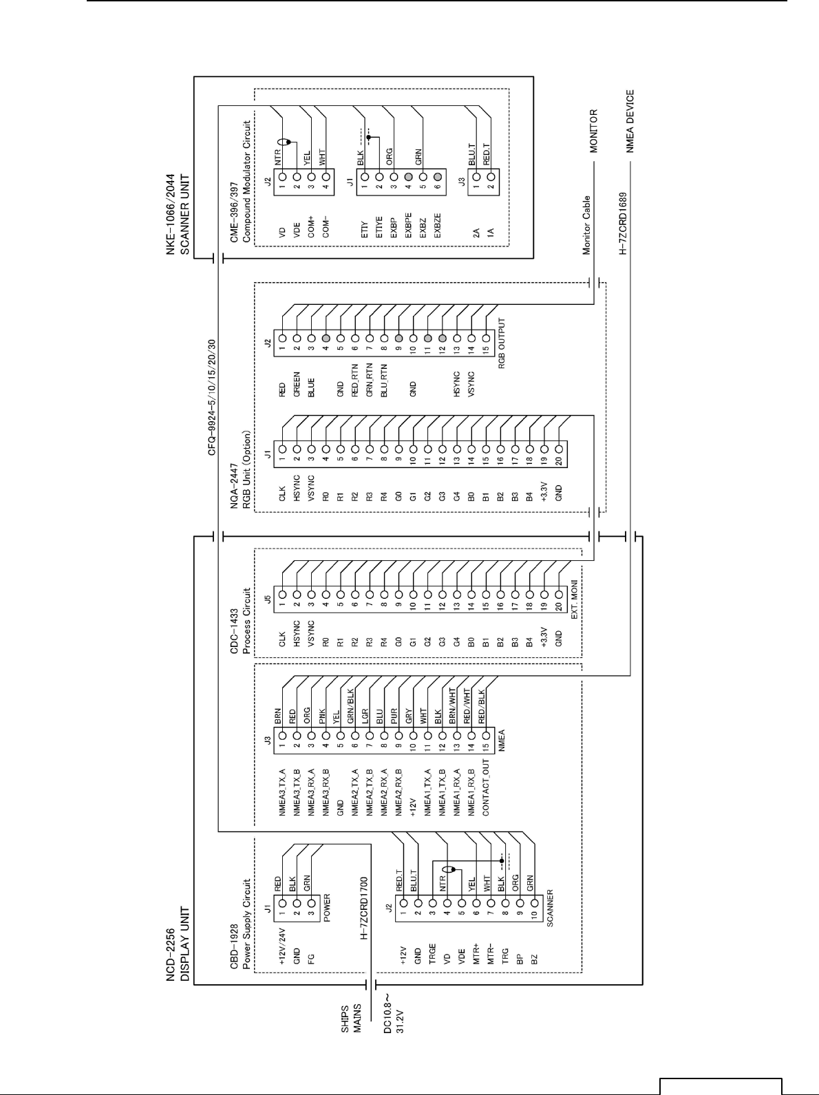
APPENDIX-5
Chapter 13 APPENDIX
JMA-1030 INTER CONNECTION DIAGRAM
FIG A5
APPENDIX-6
Chapter 13 APPENDIX
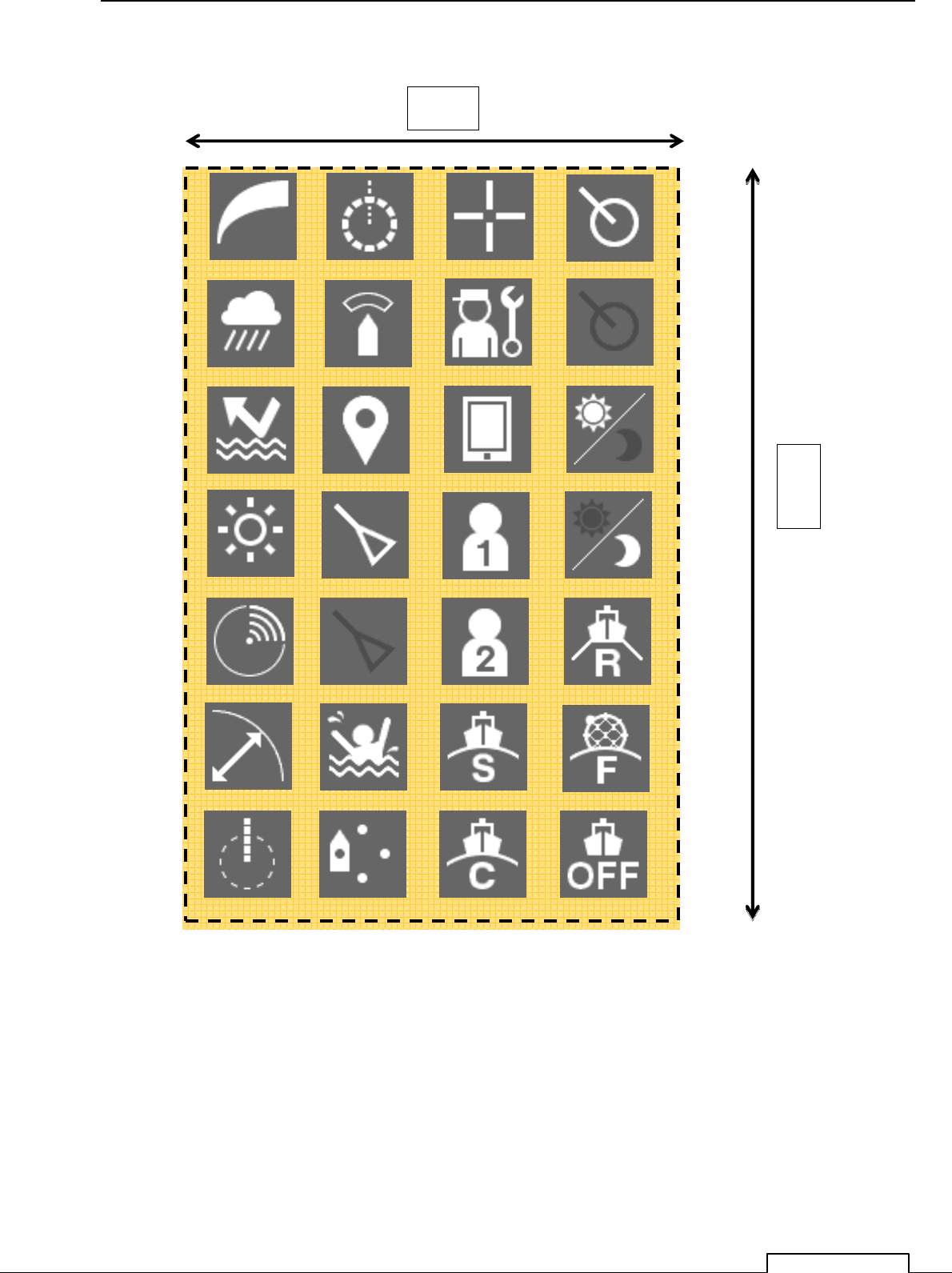
FIG A6
140
mm
90mm
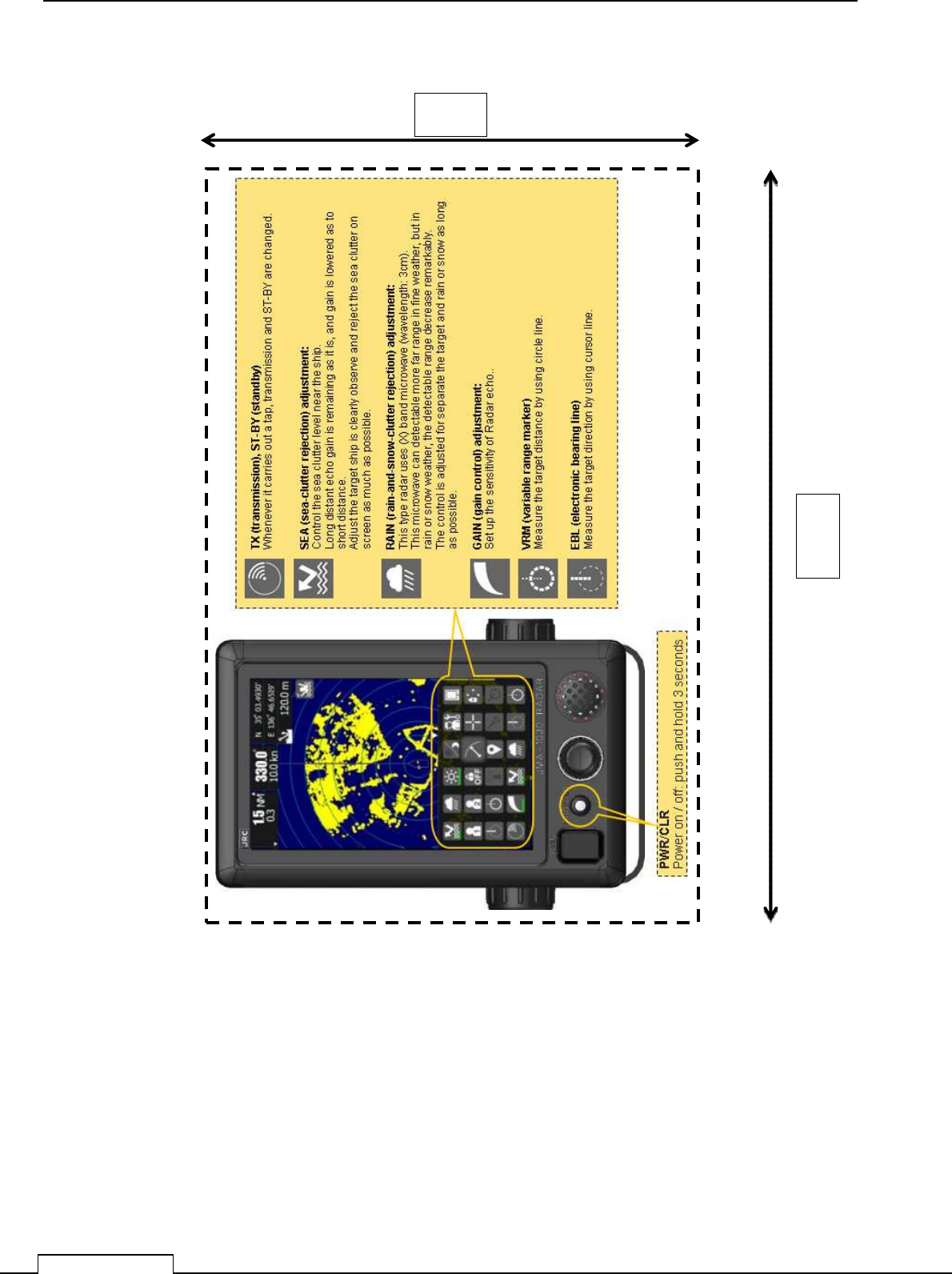
APPENDIX-7
Chapter 13 APPENDIX
OPERATION SHEET
FIG A7
140
mm
90mm
GAIN VRM CURSOR
RAIN GURDZONE SETTING
SEA MARK MENU
BRILLIANCE AIS ACTIV USER1
TX-STBY USER2
RANGE MOB MODE STANDARD
EBL OFFCENTER MODE COAST MODE OFF
MODE FIOAT
TT ST-BY
DAY
MODE RIVER
TT ACTIV
AIS SLEEP
NIGHT

APPENDIX-8
MENU FUNCTION LIST
MENU FUNCTION LIST
Main Menu
Item Setting Contents
1. RADAR Echo
1. Pulse Length
SP/MP/LP
2. IR
OFF / Low / Middle / High
3. Target Enhance
OFF / Level1 / Level2 / Level3
4. Process
OFF / 3Scan COREL / 4Scan COREL / 5Scan COREL / Remain / Peak Hold
5. Zoom
OFF / ON
6. Video Latitude
Narrow / Normal / Wide1 / Wide2
7. Video Noise Rejection
OFF / Level1 / Level2 / Level3
8. Timed TX
OFF / ON
2. Tuning
3. Motion Mode
1. Motion
RM, TM
2. Bearing Mode
HUP/NUP/CUP
4. Radar trail
1. Trails REF Level
Level1 / Level2 / Level3 / Level4
2. Time/All Combine
OFF / ON
3. Trails Mode
True/Relative
4. Trails Interval
OFF/15sec/30sec/1min/2min/3min/4min/5min/6min/10min/15min/CONT
5. Vector Length
1. Vector Mode
True/Relative
2. Vector Length
1 - 60min
6. Maker
1. Maker Mode
True/Relative
2. VRM Unit
NM/km/sm
3. EBL Bearing Mode
Heading Fix / Screen Fix
4. Range Rings(RR)
OFF / ON
7. Target
1. Function ON/OFF
1. TT
OFF / ON
2. AIS
OFF / ON
2. CPA Limit
0.1 - 9.9NM
3. TCPA Limit
1 - 99min

APPENDIX-9
MENU FUNCTION LIST
Item Setting Contents
4. CPA Ring Display
OFF / ON
5. Target Number Display
1. TT
OFF / ON
2. AIS
OFF / ON
6. ALR Alarm From AIS
OFF / ON
7. AIS Display Targets
20 / 30 / 40 / 50
8. AIS List Display
OFF / ON
8. NMEA Info. Set

APPENDIX-10
MENU FUNCTION LIST
Initial setting Menu
Item Setting Contents
1. Basic Adjustment
1. Bearing Adjustment 0.0 - 359.9
2. Range Adjustment 0 - 999
3. Tune Adjustment 0 - 127
4. Antenna Height ~5m/5~10m/10~20m/20m~
5. Noise Level 0 - 255
6. Language English/Spanish/Turkish/Indonesian/Thai/Malay/Vietnamese/
Chinese/Japanese/Korean/Russian
2. RADAR Echo
1. Main Bang Suppression
1. MBS Level 0 - 255
2. MBS Area 0 - 255
2. Target Enhance Level Level1/Level2/Level3/Level4
3. Gain Preset 0 - 255
4. STC
1. STC Curve Select Sea/River
2. STC Slope Correction 0.0 - 2.0
3. STC Offset 0 - FF
1. FTC
1. FTC Curve Select Sea/River
2. FTC Slope Correction 0.0 - 2.0
3. FTC Offset 0 - FF
6. RADAR Alarm
1. RADAR Alarm1 Level Level1/Level2/Level3/Level4
2. RADAR Alarm2 Level Level1/Level2/Level3/Level4
3. RADAR Trails
1. MAX Interval Short/Middle/Long/Super Long
2. Suppression Distance 0 - 1000
4. TT
1. Vector Constant 1 - 8
2. Gate Display OFF / ON
3. Gate Size 0 - 64
5. Scanner
1. PRF Fine Tuning 0 - 31
2. Stagger Trigger OFF / ON
3. Antenna Rotation Speed
1. SP1 0 - 7
2. SP2 0 - 7
3. SP3 0 - 7
4. MP1 0 - 7
5. MP2 0 - 7
6. LP1 0 - 7
7. LP2 (*NKE-2044 only) 0 - 7
4. PRF Mode Normal/Economy/High Power
5. Timed TX
1. TX Time 1 - 99
2. STBY Time 1 - 99
3. Adaptation ON/OFF
6. Tune Peak Adjustment 0 – 127
7. Tune Indicator Level 0 - 127
6. I/F Device
1. Heading Equipment AUTO/GYRO/Compass/GPS/Manual
2. Manual Heading 0.0 - 359.9
3. Speed Equipment GPS/Log/2axis Log/Manual
4. Manual Speed 0.0 - 100.0kn
5. MAG Compass Setting
1. Heading Correction OFF / ON
2. Correct Value W9.9 - E9.9°

APPENDIX-11
MENU FUNCTION LIST
Item Setting Contents
7. COM Port Setting
1. Baud Rate
1. NMEA1 AUTO/4800bps/38400bps
2. NMEA2 AUTO/4800bps/38400bps
3. NMEA3 AUTO/4800bps/38400bps
2. RX Port
1. GPS AUTO/NMEA1/NMEA2/NMEA3
2. Log AUTO/NMEA1/NMEA2/NMEA3
3. 2axis Log AUTO/NMEA1/NMEA2/NMEA3
4. Depth AUTO/NMEA1/NMEA2/NMEA3
5. Temperature AUTO/NMEA1/NMEA2/NMEA3
6. Wind AUTO/NMEA1/NMEA2/NMEA3
7. WPT AUTO/NMEA1/NMEA2/NMEA3
8.Rate of Turn AUTO/NMEA1/NMEA2/NMEA3
9. Rudder AUTO/NMEA1/NMEA2/NMEA3
3. TX Port
1. TTM OFF/NMEA1/NMEA2/NMEA3
2. TLL OFF/NMEA1/NMEA2/NMEA3
3. TTD OFF/NMEA1/NMEA2/NMEA3
4. TLB OFF/NMEA1/NMEA2/NMEA3
5. GGA OFF/NMEA1/NMEA2/NMEA3
6. GLL OFF/NMEA1/NMEA2/NMEA3
7. RMC OFF/NMEA1/NMEA2/NMEA3
8. GNS OFF/NMEA1/NMEA2/NMEA3
9. VTG OFF/NMEA1/NMEA2/NMEA3
10. THS OFF/NMEA1/NMEA2/NMEA3
11. HDT OFF/NMEA1/NMEA2/NMEA3
12. OSD OFF/NMEA1/NMEA2/NMEA3
13. RSD OFF/NMEA1/NMEA2/NMEA3
4. TX Data Format
1. TX Interval 1 - 9sec
2. NMEA Version V1.5/V2.0/V2.3
3. NMEA Talker Normal/GP
5. Target Info. TX
1. TX Target TT/AIS/TT-AIS
2. TTM Range Accuracy 1/2/3
3. TT Average Mode OFF / ON
4. TT Average Scan 2 - 10
8. JRC GPS
1. GPS Status
2. GPS Setting
1. NMEA Version AUTO/V1.5/V2.0/V2.3
2. Correction Method GPS Single/SBAS/Beacon/AUTO
3. Fix Mode 2D/3D/AUTO
4. Elevate Mask 5 - 89°
5. HDOP 4/10/20
6. Smoothing LL 0 - 99sec
7. Smoothing SOG 0 - 99sec
8. Smoothing COG 0 - 99sec
9. Smoothing 0 - 99sec (R29.04 - R33.99)
1 - 99sec (R26.01 - R29.03)
10. Smoothing 0sec/10sec/40sec
11. RAIM Accuracy Level OFF/10/30/50/100m
12. Exclusion Satellite
1. Exclusion Satellite1 0 - 32
2. Exclusion Satellite2 0 - 32
3. Exclusion Satellite3 0 - 32
4. Exclusion Satellite4 0 - 32
5. Exclusion Satellite5 0 - 32
6. Exclusion Satellite6 0 - 32
APPENDIX-12
MENU FUNCTION LIST
Item Setting Contents
13. Send Data
14. GPS Adjust
1. Position
2. Antenna Height 0 - 8191m
3. Time 00:00:00 - 23:59:59
4. Date 2013/1/1/ - 2099/12/31
5. Master Reset
6. Send Data
3. Beacon Setting
1. Station Select AUTO/Manual
2. Frequency 283.5 - 325.0kHz
3. Baud Rate 50 / 100 / 200bps
4. Send Data
4. SBAS Setting
1. Satellite Search AUTO/Manual
2. Ranging OFF / ON
3. SBAS Satellite Number 120 - 138
4. Send Data
9. Control
1. Touch Panel Calibration
2. Bearing Reference (*NKE-2044 only) True/Relative
3. Buzzer
1. Key ACK OFF/1 - 5
2. Operation Error OFF/1 - 5
3. CPA/TCPA OFF/1 - 5
4. AZ/Alarm Zone OFF/1 - 5
5. Target Lost OFF/1 - 5
6. System Alarm OFF/1 – 5
10. Maintenance
1. Partial Reset
1. All Menu
2. RADAR Echo
3. Function Setting
4. Initial Setting Menu
5. Main Menu
6. Adjust Menu (*NKE-2044 only)
7. System Information 1 (*NKE-2044 only)
8. System Information 2 (*NKE-2044 only)
2. All Reset
3. System Time Clear
4. Scanner Time Clear
1. TX Time Clear
2. Motor Time Clear
3. ANT to DISP Unit
4. DISP to ANT Unit
5. Table Update
1. Initial Value
1. All Menu
2. RADAR Echo
3. Function Setting
4. Initial Setting Menu
5. Main Menu
6. Adjust Menu
(*NKE-2044 only)
7. System Information 1
(*NKE-2044 only)
8. System Information 2
(*NKE-2044 only)
2. Insert Language
3. Echo Simulation (*NKE-2044 only)
4. STC Curve
5. Color Pallet (*NKE-2044 only)
APPENDIX-13
MENU FUNCTION LIST
Item Setting Contents
6. Internal Setting
1. Internal Memory to USB
1. All Menu
2. RADAR Echo
3. Function Setting
4. Initial Setting Menu
5. Main Menu
6. Mark Setting
7. Adjust Menu
(*NKE-2044 only)
8. System Information 1
(*NKE-2044 only)
9. System Information 2
(*NKE-2044 only)
2. USB to Internal Memory
1.All Menu
2. RADAR Echo
3. Function Setting
4. Initial Setting Menu
5. Main Menu
6. Mark Setting
7. Adjust Menu
(*NKE-2044 only)
8. System Information 1
(*NKE-2044 only)
9. System Information 2
(*NKE-2044 only)
7. USB Format
11. System Setting
1. Master/Slave/DEMO Master/Slave/Demo
2. Own Ship Outline
1. All Length 0.0 - 600.0m
2. All Width 0.0 - 200.0m
3. Scanner (from Bow) 0.0 - 600.0m
4. Scanner (from Cntr.) -100.0 – 100.0m
3. Unit
1. Range NM/km/sm
2. Distance NM/km/sm
3. Speed kn/ km/h /mph
4. Depth ft/fm/m/user
5. User Depth 0.1 - 10.0
6. Temperature °C /°F
7. Wind m/s / km/h / kn / Bft.
4. Move Own Ship
1. Ship's Move Method LL / COG/SOG
5. Range
1. NM
1. 0.0625NM OFF / ON
2. 0.125NM OFF / ON
3. 0.25NM OFF / ON
4. 0.5NM (*NKE-2044 only) OFF / ON
5. 0.75NM (*NKE-2044 only)
OFF / ON
4. 1NM OFF / ON
5. 2NM OFF / ON
6. 4NM OFF / ON
7. 8NM OFF / ON
8. 16NM OFF / ON
9. 24NM OFF / ON
10. 32NM OFF / ON
11. 48NM OFF / ON
APPENDIX-14
MENU FUNCTION LIST
Item Setting Contents
2. km
1. 0.15km OFF / ON
2. 0.3km OFF / ON
3. 0.5km (*NKE-2044 only) OFF / ON
4. 1.2km OFF / ON
5. 2km OFF / ON
6. 8km OFF / ON
7. 16km OFF / ON
8. 32km OFF / ON
3. sm
1. 0.0625sm OFF / ON
2. 0.125sm OFF / ON
3. 0.25sm OFF / ON
4. 1sm OFF / ON
5. 2sm OFF / ON
6. 4sm OFF / ON
7. 8sm OFF / ON
8. 16sm OFF / ON
9. 24sm OFF / ON
10. 32sm OFF / ON
11. 48sm OFF / ON
12. Display Screen
1. Own Vector Display OFF / ON
2. STBY Disp. Select Normal / Graphical / Numeric Display
3. Operation Num Disp. OFF / ON
4. Display Color
1. PPI
1. Color Black/ Blue/ White
2. Brilliance Level1/ Level2/ Level3/ Level4
2. Inner PPI (*NKE-2044 only)
1. Color
(*NKE-2044 only) Black/ Blue/ White
2. Brilliance
(*NKE-2044 only) Level1/ Level2/ Level3/ Level4
3. Character
1. Color White/Cyan/Green/Black/Red/Gold/Amber
2. Brilliance Level1/ Level2/ Level3/ Level4
4. RADAR Echo
1. Color Yellow/Green/Blue/White/Magenta/Gold/Amber/Color
2. Brilliance Level1/ Level2/ Level3/ Level4
5. RADAR Trails (Time)
1. Color Green/Blue/Cyan
2. Brilliance Level1/ Level2/ Level3/ Level4
6. RADAR Trails (All)
1. Color Green/Blue/Cyan
2. Brilliance Level1/ Level2/ Level3/ Level4
7. Own Ship's
1. Color Cyan/Green/Red/White/Gold/Amber
2. Brilliance Level1/ Level2/ Level3/ Level4
8. Target (TT/AIS)
1. Color Cyan/Green/White
2. Brilliance Level1/ Level2/ Level3/ Level4
9. EBL/VRM
1. Color Cyan/Black/Magenta/White
2. Brilliance Level1/ Level2/ Level3/ Level4
10. Range Ring
1. Color Cyan/Green/Red/White/Gold/Amber
2. Brilliance Level1/ Level2/ Level3/ Level4
11. Cursor
1. Color White/Red/Magenta/Yellow
2. Brilliance Level1/ Level2/ Level3/ Level4

APPENDIX-15
MENU FUNCTION LIST
Item Setting Contents
12. AZ/Alarm Zone
1. Color White/Green/Orange/Black/Red
2. Brilliance Level1/ Level2/ Level3/ Level4
5. Waypoint Display ON/OFF
6. AIS Filter 0.0 - 48.0
13. Error Alarm Mask
1. Scanner
1. Scanner(Time Out)
1. Alarm Sensitivity OFF / ON
2. Sensitivity Time 0 - 999sec
2. Scanner(Data)
1. Alarm Sensitivity OFF / ON
2. Sensitivity Time 0 – 999sec
3. Scanner(Video)
1. Alarm Sensitivity OFF / ON
2. Sensitivity Time 0 - 999sec
4. Scanner (Trigger)
1. Alarm Sensitivity OFF / ON
2. Sensitivity Time 0 - 999sec
5. Scanner(AZI)
1. Alarm Sensitivity OFF / ON
2. Sensitivity Time 0 -999sec
6. Scanner(HL)
1. Alarm Sensitivity OFF / ON
2. Sensitivity Time 0 -999sec
7. Scanner(MHV)
1. Alarm Sensitivity OFF / ON
2. Sensitivity Time 0 -999sec
8. Scanner(Heater)
1. Alarm Sensitivity OFF / ON
2. Sensitivity Time 0 -999sec
2. Display Unit
1. Display Unit(Video)
1. Alarm Sensitivity OFF / ON
2. Sensitivity Time 0 -999sec
2. Display Unit(Trigger)
1. Alarm Sensitivity OFF / ON
2. Sensitivity Time 0 -999sec
3. Display Unit(AZI)
1. Alarm Sensitivity OFF / ON
2. Sensitivity Time 0 -999sec
4. Display Unit(HL)
1. Alarm Sensitivity OFF / ON
2. Sensitivity Time 0 -999sec
5. Display Unit(DSP)
1. Alarm Sensitivity OFF / ON
2. Sensitivity Time 0 -999sec
6. COM Port
1. Alarm Sensitivity OFF / ON
3. Connection Device (*NKE-2044 only)
1. GYRO(Time Out) (*NKE-2044 only)
1. Alarm Sensitivity
(*NKE-2044 only) OFF / ON
2. Sensitivity Time
(*NKE-2044 only) 0 -999sec
2. Log(Time Out) (*NKE-2044 only)
1. Alarm Sensitivity
(*NKE-2044 only) OFF / ON
2. Sensitivity Time
(*NKE-2044 only) 0 -999sec
3. GPS(Time Out) (*NKE-2044 only)
1. Alarm Sensitivity
(*NKE-2044 only) OFF / ON
2. Sensitivity Time
(*NKE-2044 only) 0 -999sec

APPENDIX-16
MENU FUNCTION LIST
Item Setting Contents
4. RX Data
1. GYRO
1. Alarm Sensitivity OFF / ON
2. Sensitivity Time 0 -999sec
2. Compass
1. Alarm Sensitivity OFF / ON
2. Sensitivity Time 0 -999sec
3. Log
1. Alarm Sensitivity OFF / ON
2. Sensitivity Time 0 -999sec
4. 2Axis Log
1. Alarm Sensitivity OFF / ON
2. Sensitivity Time 0 -999sec
5. Course/Speed
1. Alarm Sensitivity OFF / ON
2. Sensitivity Time 0 -999sec
6. Depth
1. Alarm Sensitivity OFF / ON
2. Sensitivity Time 0 -999sec
7. Temperature
1. Alarm Sensitivity OFF / ON
2. Sensitivity Time 0 -999sec
8. Wind
1. Alarm Sensitivity OFF / ON
2. Sensitivity Time 0 -999sec
9. Rate of Turn
1. Alarm Sensitivity OFF / ON
2. Sensitivity Time 0 -999sec
10. Rudder
1. Alarm Sensitivity OFF / ON
2. Sensitivity Time 0 -999sec
11. WPT
1. Alarm Sensitivity OFF / ON
2. Sensitivity Time 0 -999sec
12. LAT/LON
1. Alarm Sensitivity OFF / ON
2. Sensitivity Time 0 -999sec
13. Datum
1. Alarm Sensitivity OFF / ON
2. Sensitivity Time 0 -999sec
14. Status
1. Alarm Sensitivity OFF / ON
2. Sensitivity Time 0 -999sec
15. HDOP
1. Alarm Sensitivity OFF / ON
2. Sensitivity Time 0 -999sec
16. AIS
1. Alarm Sensitivity OFF / ON
2. Sensitivity Time 0 -999sec
14. Test
1. System Information
1. Indicator Software 1.0.0
2. Boot 01.06
3. DSP (MC) 01.00.00.00
4. DSP (V) 01.00.00.00
5. Test Bench 01.04
6. Scanner Software 04.02
7. Update 01.06
APPENDIX-17
MENU FUNCTION LIST
Item Setting Contents
2. System Time
1. Scanner Transmit Time
2. Scanner Motor Time
3. Scanner Running Time
4. Indicator Running Time
3. Scanner Information
1. Scanner Transmit Power
2. Motor Type
3. Magnetron Current
4. Hardware Information
1. Serial Number
2. MAC Address
5. Error Log
1. Display
2. Erase
6. Line Monitor
1. Scanner
2. NMEA1
3. NMEA2
4. NMEA3
7. Self Test
1. Key Test
2. Touch Panel Test
3. Buzzer Test
4. Key Light Test
5. Monitor Display Test
Pattern1
Pattern2
Pattern3
Pattern4
Pattern5
Pattern6
Pattern7
RGB Setting
Red
Green
Blue
Display
6. Memory Test
1. SDRAM
2. Flash ROM
3. USB
7. Line Test
1. Scanner
2. NMEA1 or GPS(JRC)
3. NMEA2
4. NMEA3 or NSK
8. Scanner Test
1. SSW Off
2. BP
3. BZ
4. Mod.HV
5. Trigger
6. Video

APPENDIX-18
MENU FUNCTION LIST

JRC website http://www.jrc.co.jp/
Marine Service Department
Telephone: +81-3-3492-1305
Facsimile: +81-3-3379-1420
e-mail tmsc@.jrc.co.jp
Amsterdam branch
Telephone: +31-(0)20-658-0750
Facsimile +31-(0)20-658-0755
e-mail service@jrceurope.com
Seattle branch
Telephone: +1-(0)206-654-5644
Facsimile: +1-(0)206-654-7030
e-mail service@jrcamerica.com
01JTM ISO 9001 and ISO 14001 Certified
Code No.7ZPRD0895
Dec, 2013 creation The 1st edition JRC
Not use the asbestos