Japan Radio NKE2043 MARINE RADAR User Manual NKE2063UserMan
Japan Radio Co Ltd. MARINE RADAR NKE2063UserMan
UserManual.wiki
>
Japan Radio
>
NKE2043 User Manual
>
Users Manual 2
Contents
1.
Users Manual 2
2.
Users Manual 1
3.
Users Manual 3
4.
Users Manual 4
Users Manual 2
Navigation menu
Upload a User Manual
Namespaces
Wiki Guide
HTML
PDF
Info
Views
User Manual
Discussion / Help
Navigation
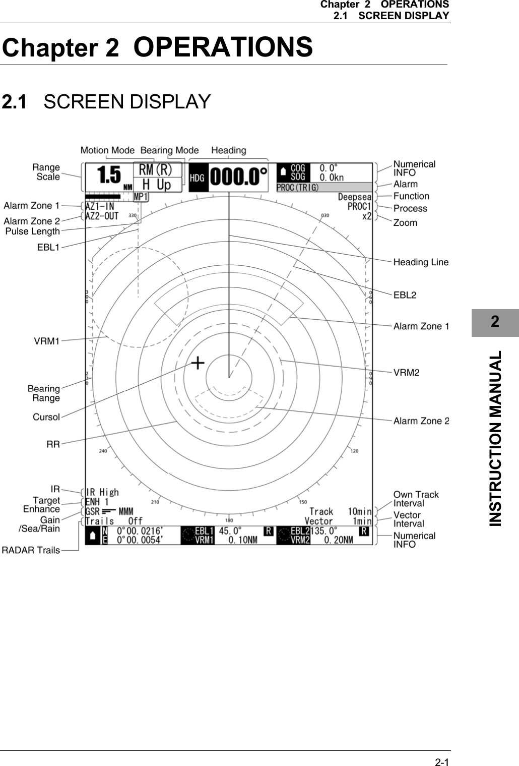
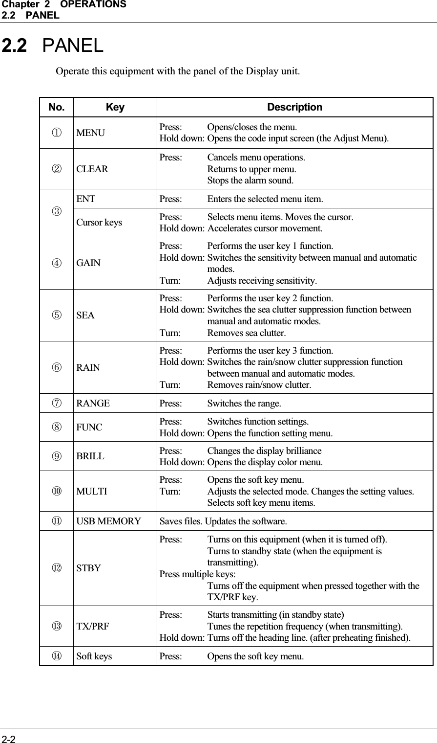
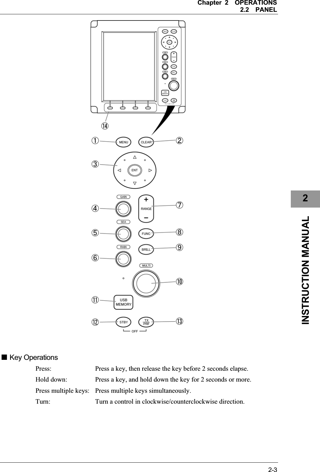
![Chapter 2OPERATIONS2.3POWER ON/OFF 2-42.3 POWER ON/OFF CAUTIONA malfunction may occur if the power in the ship is instantaneously interrupted during operation of the radar. In this case, the power should be turned on again. Note: z Wait for about 2 seconds before turning on the power again. z Immediately after the radar is installed, at start of the system after it has not been used for a long time, or after the magnetron is replaced, preheat the equipment in the standby state for 20 to 30 minutes before setting it into the transmit state. z If the preheating time is short, the magnetron causes sparks, resulting in its unstable oscillation. Start transmission on a short-pulse range and change the range to the longer pulse ranges in turn. If the transmission is unstable in the meantime, immediately place the system back into the standby state and maintain it in the standby state for 5 to 10 minutes before restarting the operation. Repeat these steps until the operation is stabilized. Power On 1Press the [STBY] key on the display unit to turn on the display unit. The display unit is turned on, and the preheating time screen is displayed. When the preheating time is over, the preheating time screen disappears.](https://usermanual.wiki/Japan-Radio/NKE2043.Users-Manual-2/User-Guide-1634841-Page-4.png)
![Chapter 2OPERATIONS2.3POWER ON/OFF 2-52INSTRUCTION MANUAL Starting transmission 1Press the [TX/PRF] key. The radar starts transmission and the antenna starts rotating. Reference:The radar cannot start transmission if you press the [TX/PRF] key while the preheating time is displayed. Stopping transmission 1Press the [STBY] key on the display unit. The radar stops transmission and the antenna stops rotating. Maintain the standby state if radar observation is restarted in a relatively short time. Only pressing the [TX/PRF] key starts observation. Power Off 1Press the [STBY] key and the [TX/PRF] key simultaneously. The system is turned off. WARNINGWhen conducting maintenance work, make sure to turn off the power and unplug the power connector J1 of the display unit so that the power supply to the equipment is completely cut off. Some equipment components can carry electrical current even after the power switch is turned off, and conducting maintenance work without unplugging the power connector may result in electrocution, equipment failure, or accidents.](https://usermanual.wiki/Japan-Radio/NKE2043.Users-Manual-2/User-Guide-1634841-Page-5.png)
![Chapter 2OPERATIONS2.4SENSITIVITY ADJUSTMENT 2-62.4 SENSITIVITY ADJUSTMENT Sensitivity can be adjusted. Adjust the noise on the display unit to achieve better observation state. CAUTIONIf sensitivity is set too high, unnecessary signals such as noises in the receiver and false echoes increase to lower target visibility. At the same time, if sensitivity is set too low, detection of targets such as ships and dangerous objects may be hindered. Therefore, sensitivity must always be set to an optimal level. Noise Adjustment 1Turn the [GAIN] control. Turn the [GAIN] control clockwise to increase sensitivity. Turn the [GAIN] control counterclockwise to decrease sensitivity. The sensitivity adjustment screen appears when turning the [GAIN] control. Sensitivity can be adjusted between 0 and 100. When turning the [GAIN] control, the gain control indication is stretched or shrunk.](https://usermanual.wiki/Japan-Radio/NKE2043.Users-Manual-2/User-Guide-1634841-Page-6.png)
![Chapter 2OPERATIONS2.4SENSITIVITY ADJUSTMENT 2-72INSTRUCTION MANUAL z [GAIN] Control Turning the [GAIN] control clockwise increases receiving sensitivity and extends the radar observation range. If the sensitivity is too high, the receiver noise increases reducing the contrast between the targets and the background video. As a result, the targets become obscure on the radar display. To observe densely crowded targets or short-range targets, turn the [GAIN] control counterclockwise to reduce the sensitivity so that the targets are easy to observe. However, be careful not to overlook important small targets. Switching to Manual/Automatic Mode 1Hold down the [GAIN] control. The sensitivity can be switched between manual and automatic modes. The mode is indicated as shown below. ](https://usermanual.wiki/Japan-Radio/NKE2043.Users-Manual-2/User-Guide-1634841-Page-7.png)
![Chapter 2OPERATIONS2.5SEA CLUTTER SUPPRESSION 2-82.5 SEA CLUTTER SUPPRESSION The sea clutter suppression function suppresses sea clutter returns. CAUTIONWhen using the sea clutter suppression function, never set the suppression level too high canceling out all image noises from the sea surface at close range. Detection of not only echoes from waves but also targets such as other ships or dangerous objects will become inhibited. When using the sea clutter suppression function, make sure to choose the most appropriate image noise suppression level. Manual Sea Clutter Suppression Function Adjust the sea clutter returns on the display unit to achieve better observation state. 1Turn the [SEA] control. Turn the [SEA] control clockwise to suppress sea clutter returns. Turn the [SEA] control counterclockwise to intensify sea clutter returns. The sea clutter suppression adjustment screen appears when turning the [SEA] control. Sea clutter suppression can be adjusted between 0 and 100. When turning the [SEA] control, the sea clutter control indication is stretched or shrunk.](https://usermanual.wiki/Japan-Radio/NKE2043.Users-Manual-2/User-Guide-1634841-Page-8.png)
![Chapter 2OPERATIONS2.5SEA CLUTTER SUPPRESSION 2-92INSTRUCTION MANUAL z [SEA] Control The sea clutter suppression function suppresses sea clutter returns by decreasing the receiving sensitivity on a short range. Turn the [SEA] control clockwise to heighten the effect of sea clutter suppression. However, be careful that excessive suppression causes low signal-strength targets such as buoys and boats to disappear from the radar display. Automatic Sea Clutter Suppression Function Sea clutter suppression can be performed in accordance with the level of sea clutter. Use this automatic mode when sea clutter returns vary in direction. 1Hold down the [SEA] control. Automatic function is selected. Even when the automatic function is selected, you can manually perform fine adjustments by turning the [SEA] control. The sea clutter suppression adjustment screen appears when turning the [SEA]control. Sea clutter suppression can be adjusted between 0 and 100. When the sea clutter suppression (Auto) is set to "0" When the sea clutter suppression (Auto) is set to "10"](https://usermanual.wiki/Japan-Radio/NKE2043.Users-Manual-2/User-Guide-1634841-Page-9.png)
![Chapter 2OPERATIONS2.5SEA CLUTTER SUPPRESSION 2-10 Canceling Automatic Sea Clutter Suppression Function 1Hold down the [SEA] control. Automatic function is canceled. The mode is indicated as shown below. Reference:When the automatic mode is selected for the sea clutter suppression function, the rain/snow clutter suppression function is switched to the manual mode. The sea clutter suppression function (Auto) and the rain/snow clutter suppression function (Auto) cannot be selected at the same time. ](https://usermanual.wiki/Japan-Radio/NKE2043.Users-Manual-2/User-Guide-1634841-Page-10.png)
![Chapter 2OPERATIONS2.6RAIN/SNOW CLUTTER SUPPRESSION 2-112INSTRUCTION MANUAL 2.6 RAIN/SNOW CLUTTER SUPPRESSION This function suppresses rain/snow clutter returns. CAUTIONWhen using the sea clutter suppression function, never set the suppression level too high canceling out all image noises from the rain or snow at close range. Detection of not only echoes from the rain or snow but also targets such as other ships or dangerous objects will become inhibited. When using the sea clutter suppression function, make sure to choose the most appropriate image noise suppression level. Manual Rain/Snow Clutter Suppression Function Adjust the rain/snow clutter returns on the display unit to achieve better observation state. 1Turn the [RAIN] control. Turn the [RAIN] control clockwise to suppress rain/snow clutter returns. Turn the [RAIN] control counterclockwise to intensify rain/snow clutter returns. The rain/snow clutter suppression adjustment screen appears when turning the [RAIN]control. Rain/snow clutter suppression can be adjusted between 0 and 100. When turning the [RAIN] control, the rain/snow clutter control indication is stretched or shrunk.](https://usermanual.wiki/Japan-Radio/NKE2043.Users-Manual-2/User-Guide-1634841-Page-11.png)
![Chapter 2OPERATIONS2.6RAIN/SNOW CLUTTER SUPPRESSION 2-12z [RAIN] Control When the [RAIN] control is turned clockwise, targets hidden by rain/snow clutter returns appear on the radar display. However, be careful that excessive suppression may cause small targets to be overlooked. Since the rain/snow clutter suppression function also has the effect of suppressing sea clutter, the suppression efficiency improves when using with the [SEA] control. In general, set the value to "0". Automatic Rain/Snow Clutter Suppression Function Rain/snow clutter suppression can be performed in accordance with the level of rain/snow clutter. Use this automatic mode when rain/snow clutter returns vary in direction.1Hold down the [RAIN] control. Automatic function is selected. Even when the automatic function is selected, you can manually perform fine adjustments by turning the [RAIN] control. The rain/snow clutter suppression adjustment screen appears when turning the [RAIN] control. Rain/snow clutter suppression can be adjusted between 0 and 100. When the rain/snow clutter suppression (Auto) is set to "0" When the rain/snow clutter suppression (Auto) is set to "10"](https://usermanual.wiki/Japan-Radio/NKE2043.Users-Manual-2/User-Guide-1634841-Page-12.png)
![Chapter 2OPERATIONS2.6RAIN/SNOW CLUTTER SUPPRESSION 2-132INSTRUCTION MANUAL Switching to Manual/Automatic Mode 1Hold down the [RAIN] control. Automatic function is canceled. The mode is indicated as shown below. Reference:When the automatic mode is selected for the rain/snow clutter suppression function, the sea clutter suppression function is switched to the manual mode. The sea clutter suppression function (Auto) and the rain/snow clutter suppression function (Auto) cannot be selected at the same time. ](https://usermanual.wiki/Japan-Radio/NKE2043.Users-Manual-2/User-Guide-1634841-Page-13.png)
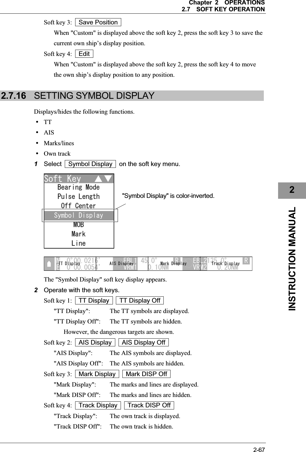
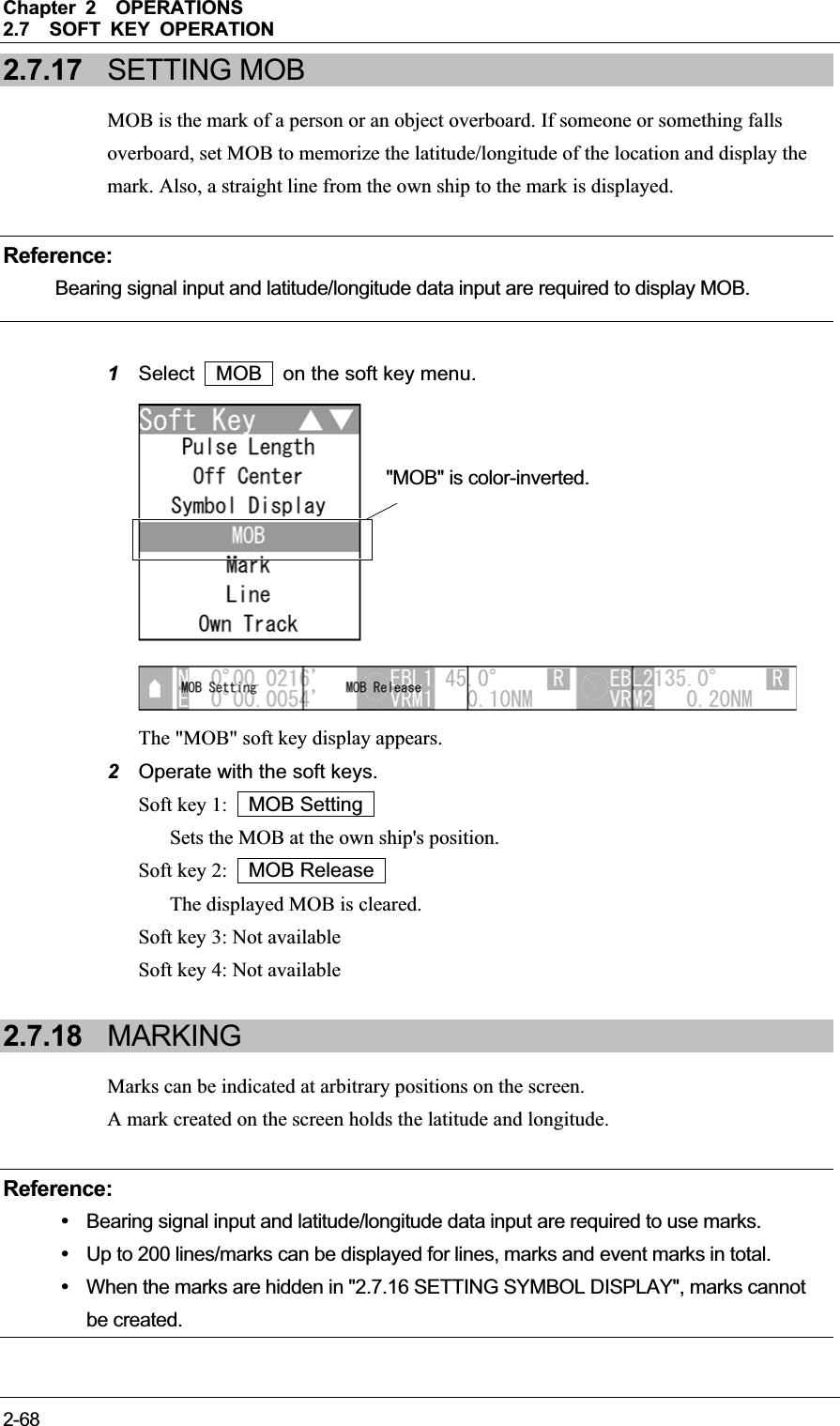
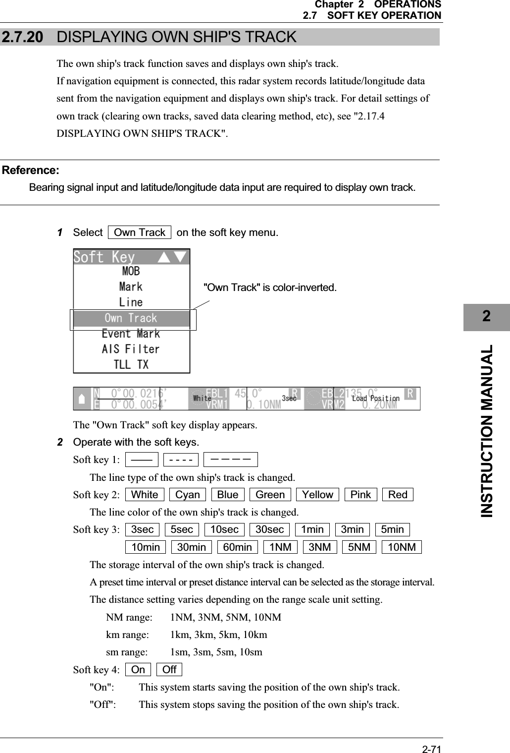
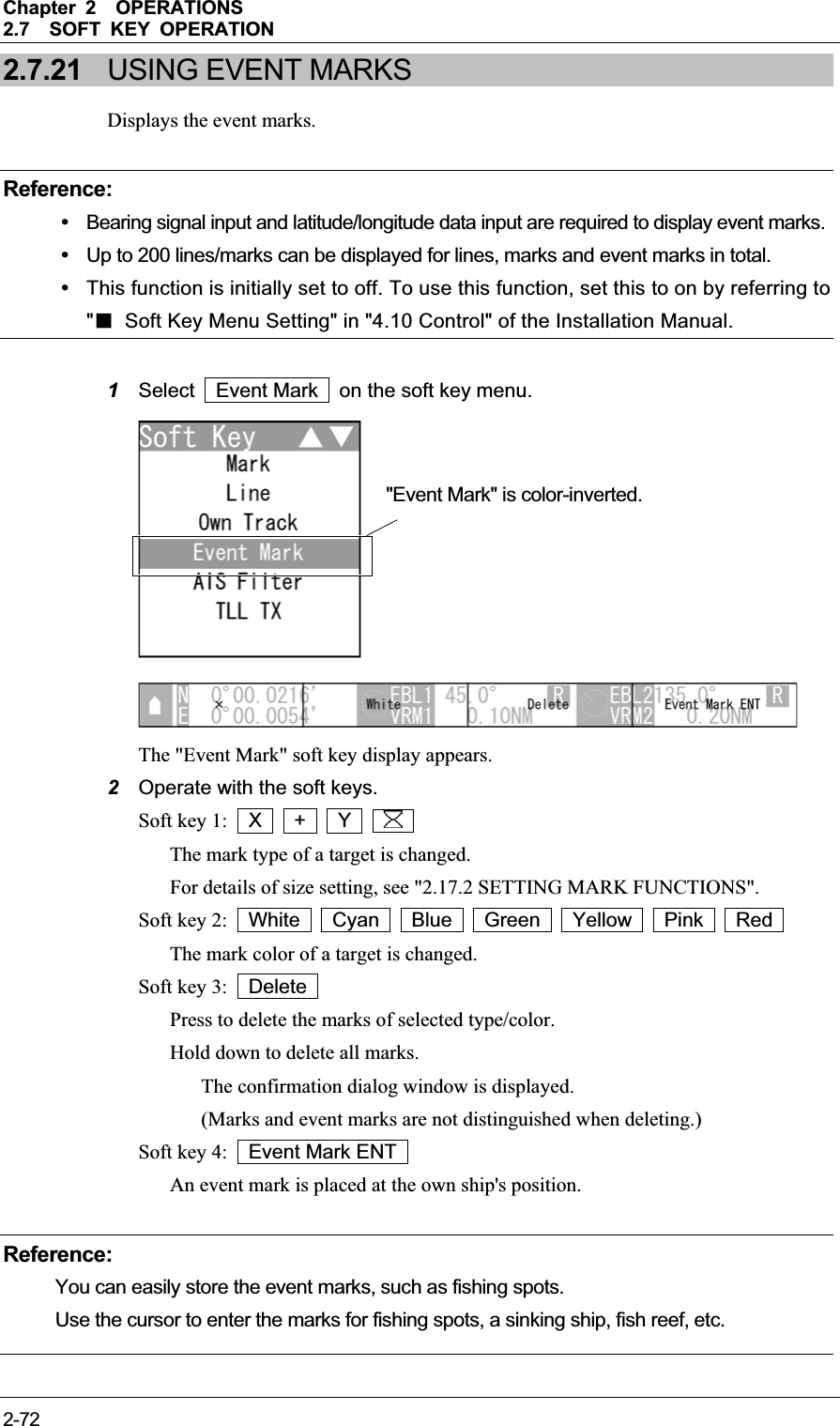
![Chapter 2OPERATIONS2.7SOFT KEY OPERATION 2-142.7 SOFT KEY OPERATION This radar can be operated with the soft keys and the MULTI control placed on the front panel of the display unit. You can access to functions without opening the menu screen. To change the default settings, press the [MENU] key to open the menu screen. This section describes the operation with the soft keys and the MULTI control. Keys for operation y Soft keys 1, 2, 3 and 4 y [MULTI] control y [CLEAR] key Soft Key Operations (Example: Opening "Display Screen") This section describes how to operate with the soft keys shown below. yTUNE/PRFyDisplay Screen yTM/RMyBearing Mode yPulse Length yOff Center ySymbol Display yMOByMarkyLineyOwn Track yEvent Mark yAIS Filter yTLL TX](https://usermanual.wiki/Japan-Radio/NKE2043.Users-Manual-2/User-Guide-1634841-Page-14.png)
![Chapter 2OPERATIONS2.7SOFT KEY OPERATION 2-152INSTRUCTION MANUAL 1Press the [[MULTI] control. 2Turn the [MULTI] control to select Display Screen on the soft key menu. Reference:When a certain time elapses without any key operation after selecting an item on the soft key menu, the soft key menu and the soft key display automatically disappear. "Display Screen" is color-inverted. Press the [MULTI] control.](https://usermanual.wiki/Japan-Radio/NKE2043.Users-Manual-2/User-Guide-1634841-Page-15.png)
![Chapter 2OPERATIONS2.7SOFT KEY OPERATION 2-16z Turning the [MULTI] control clockwise To select "Own Track" - "TLL TX" XۂWReference:When the item at the bottom of the soft key menu is color-inverted, the soft key menu does not scroll any more even if the control is turned clockwise. "Own Track" is color-inverted. "Event Mark" is color-inverted. "TLL TX" is color-inverted. "AIS Filter" is color-inverted.](https://usermanual.wiki/Japan-Radio/NKE2043.Users-Manual-2/User-Guide-1634841-Page-16.png)
![Chapter 2OPERATIONS2.7SOFT KEY OPERATION 2-172INSTRUCTION MANUAL z Turning the [MULTI] control counterclockwise To select "VRM2" - "EBL1" XۂWReference:When the item at the top of the soft key menu is color-inverted, the soft key menu does not scroll any more even if the control is turned counterclockwise. "VRM2" is color-inverted. "VRM1" is color-inverted. "EBL1" is color-inverted. "EBL2" is color-inverted.](https://usermanual.wiki/Japan-Radio/NKE2043.Users-Manual-2/User-Guide-1634841-Page-17.png)
![Chapter 2OPERATIONS2.7SOFT KEY OPERATION 2-18z Soft key 1 The screen changes to the layout set in the section "4.13.7 LOCATION CHANGE" - "1. Screen1". z Soft key 2 The screen changes to the layout set in the section "4.13.7 LOCATION CHANGE" - "2. Screen2". "Screen 1" is color-inverted."Screen 2" is color-inverted.Press the [soft key 1].Press the [soft key 2].](https://usermanual.wiki/Japan-Radio/NKE2043.Users-Manual-2/User-Guide-1634841-Page-18.png)
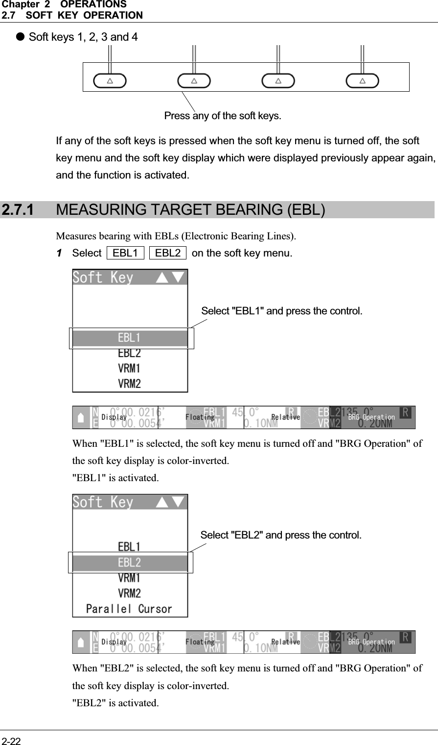
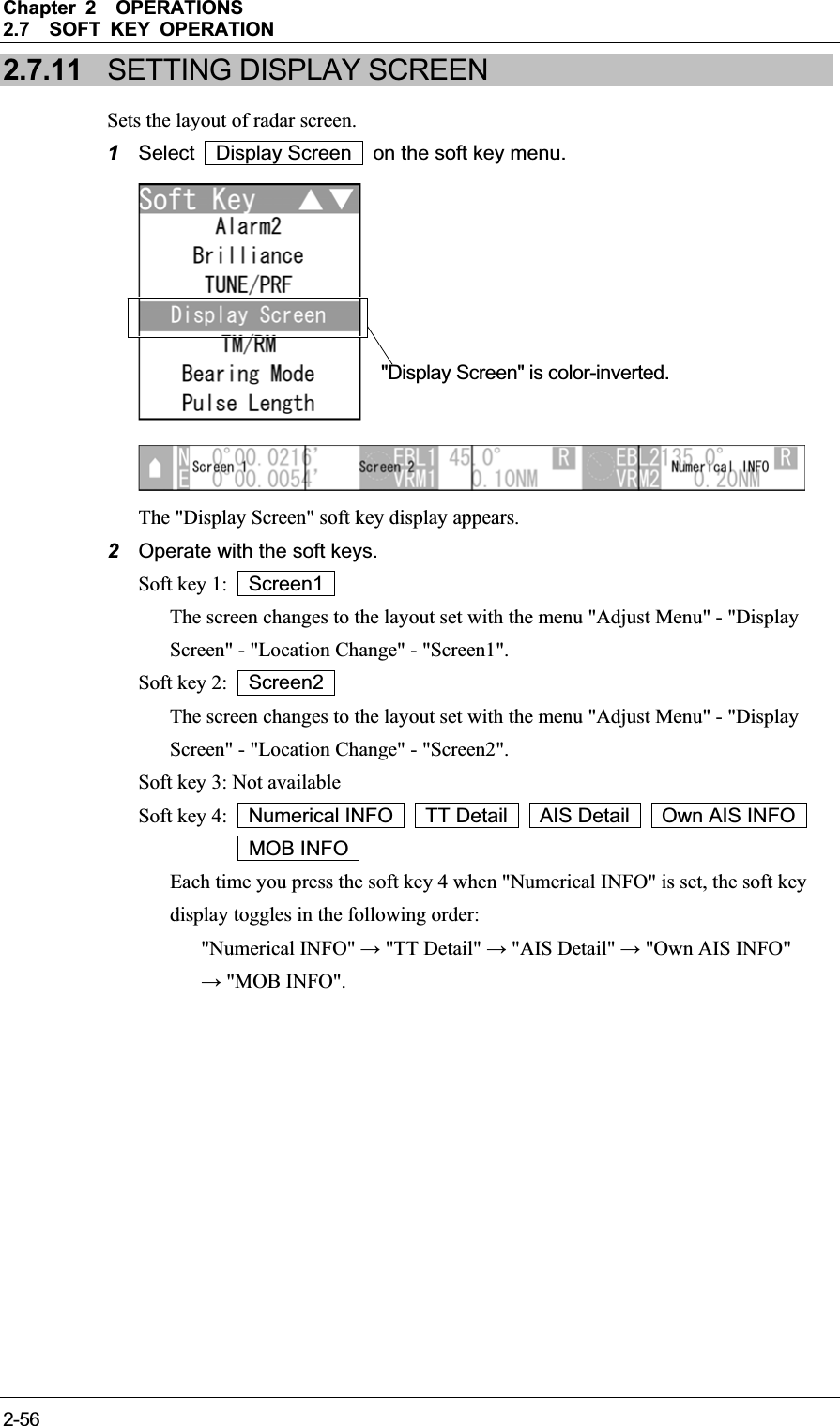
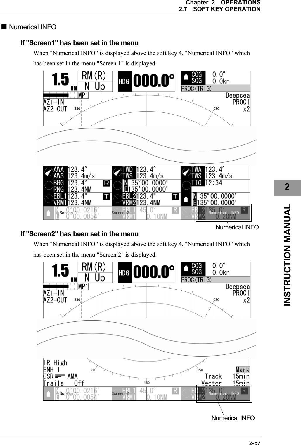
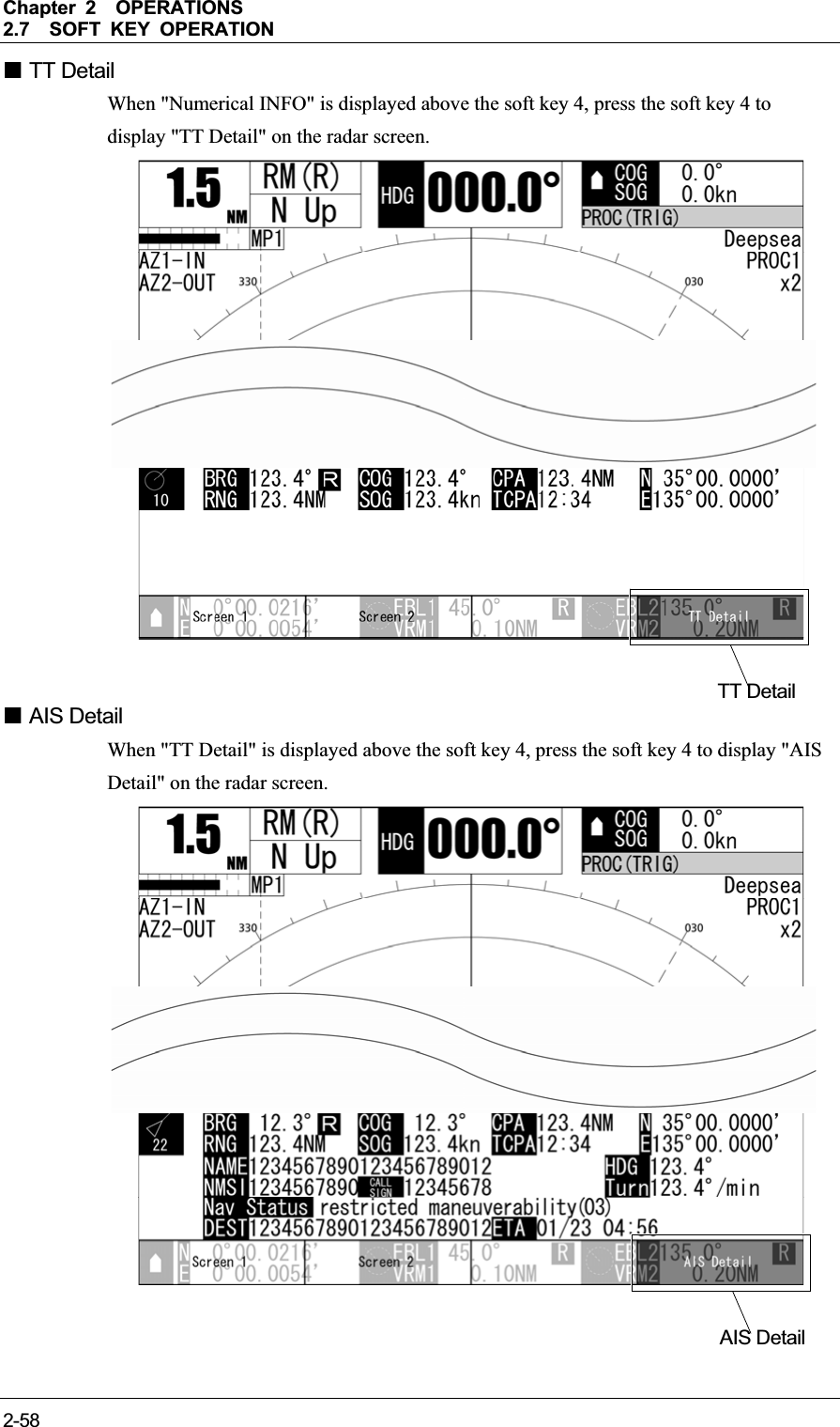
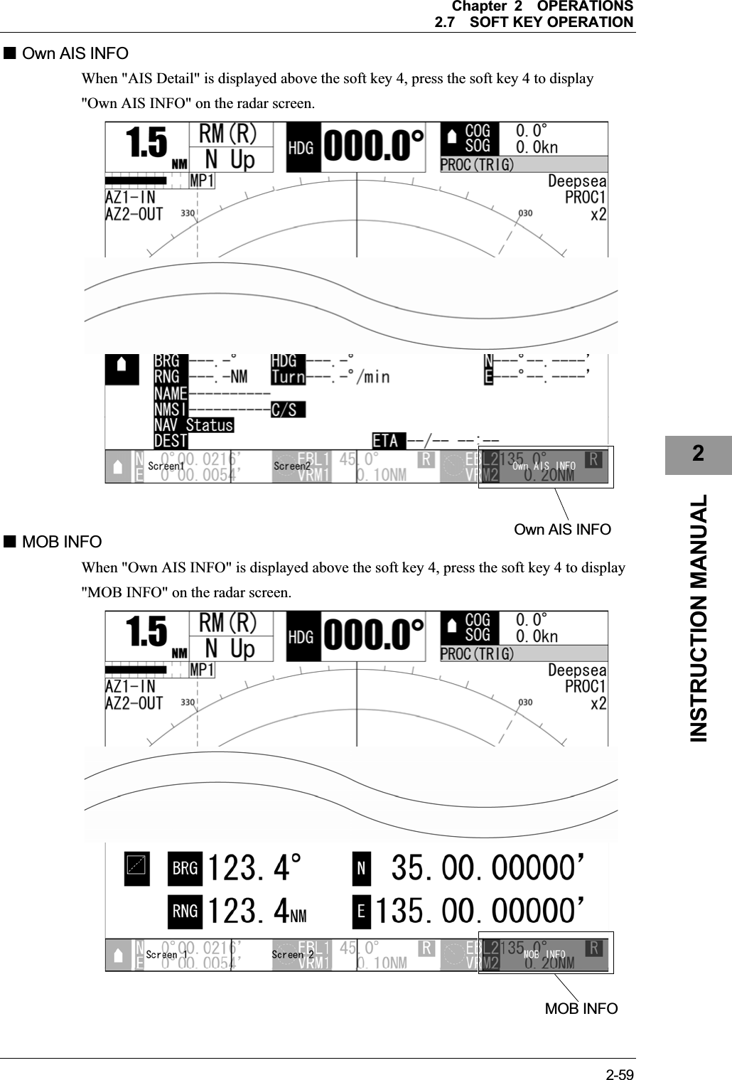
![Chapter 2OPERATIONS2.7SOFT KEY OPERATION 2-192INSTRUCTION MANUAL z Soft key 4 Each time you press the soft key 4 when "Numerical INFO" is set, the soft key display toggles in the following order: "Numerical INFO" ĺ "TT Detail" ĺ "AIS Detail" ĺ "Own AIS INFO" ĺ "MOB INFO". z Closing the soft key menu Press the [CLEAR] key to turn off the soft key menu and the soft key display. z Soft keys 1, 2, 3 and 4 If any of the soft keys is pressed when the soft key menu is turned off, the soft key menu and the soft key display which were displayed previously appear again."Numerical INFO" is color-inverted.Press the [soft key 4].Press any of the soft keys.](https://usermanual.wiki/Japan-Radio/NKE2043.Users-Manual-2/User-Guide-1634841-Page-19.png)
![Chapter 2OPERATIONS2.7SOFT KEY OPERATION 2-20 "Soft key Operations (Example: Opening "Brilliance") This section describes how to operate with the soft keys shown below. yEBL1yEBL2yVRM1yVRM2yParallel Cursor yVector Length yRADAR Trails yAISyTTyAlarm1 yAlarm2 yBrilliance1Press a soft key. 2Turn the [MULTI] control to select Brilliance on the soft key menu. The soft key menu disappears and "Monitor BRILL" of the soft key display is color-inverted."Brilliance" is activated. Select "Brilliance" and press the control. Press the [MULTI] control.](https://usermanual.wiki/Japan-Radio/NKE2043.Users-Manual-2/User-Guide-1634841-Page-20.png)
![Chapter 2OPERATIONS2.7SOFT KEY OPERATION 2-212INSTRUCTION MANUAL Reference:Perform the same operations for the other soft key menu items to activate the functions. z Soft key 1 When the soft key 1 is pressed, the display color is switched. z Soft key 2 "Monitor BRILL" is color-inverted, and is activated. Press the [BRILL] key to adjust at eight levels. Also, you can turn the [MULTI] control to change the level. z Setting with the soft key menu To determine the setting of the soft key menu item, press one of the followings: y [Multi] control y [CLEAR] key The soft key menu item is determined, then the soft key menu and the soft key display are turned off and the setting is finished. "Monitor BRILL" is color-inverted. Press the [soft key 1].Press the [softkey 2]."Monitor BRILL" is color-inverted.](https://usermanual.wiki/Japan-Radio/NKE2043.Users-Manual-2/User-Guide-1634841-Page-21.png)
![Chapter 2OPERATIONS2.7SOFT KEY OPERATION 2-232INSTRUCTION MANUAL 2Operate with the soft keys. Soft key 1: Display Off Display "Display Off": "EBL1"/"EBL2" is not displayed. "Display": "EBL1"/"EBL2" is displayed. Reference:When "Display Off" is selected for the soft key 1, the equipment performs the followings: y EBL is not displayed. y The soft key menu and the soft key display disappears, and EBL function is terminated. Soft key 2: Floating When pressing the soft key 2, "Floating" is color-inverted. The starting point of the currently operating EBL can be switched from the center of the radar display (floating off) to floating state. Press the cursor keys to move the starting point of "EBL1"/"EBL2". Press the [ENT] key at the starting point of "EBL1"/"EBL2" you want to move. The starting point of "EBL1"/"EBL2" is determined. Reference:The floating position of the EBL’s starting point can be fixed on the radar display or at specific latitude and longitude. Floating function must be turned on to use floating. For details of settings, refer to "2.11.1 SETTING OPERATIONS FOR EBLS (ELECTRONIC BEARING LINES)". Soft key 3: True Relative Sets whether to display EBLs (Electronic Bearing Lines) in true bearing mode or relative bearing mode. "True": "EBL1"/"EBL2" is displayed in true bearing mode. "Relative": "EBL1"/"EBL2" is displayed in relative bearing mode. Reference:Bearing signal input is required to display true motion. ](https://usermanual.wiki/Japan-Radio/NKE2043.Users-Manual-2/User-Guide-1634841-Page-23.png)
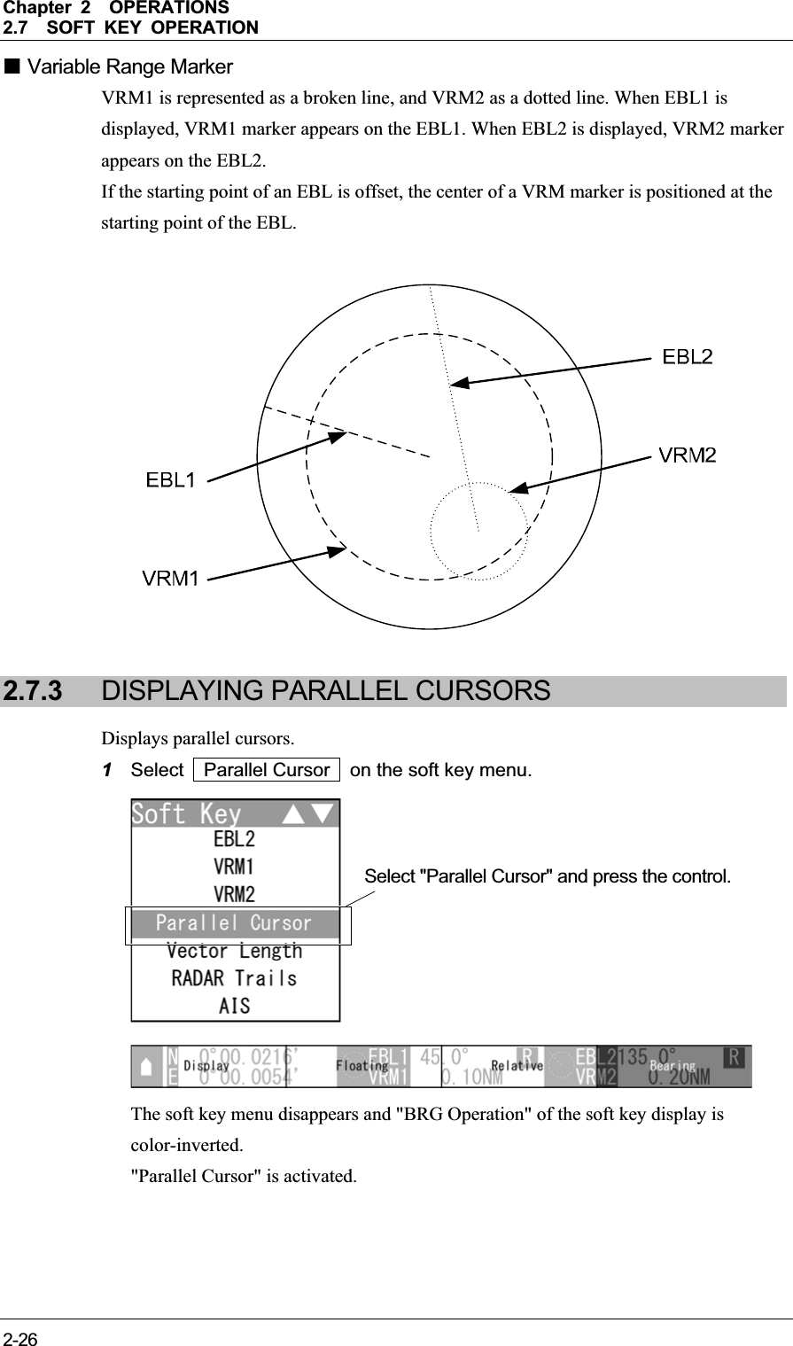
![Chapter 2OPERATIONS2.7SOFT KEY OPERATION 2-24Soft key 4: BRG Operation When "EBL1" or "EBL2" of the soft key menu is selected, "BRG Operation" of the soft key display is color-inverted. Turn the [MULTI] control to change the direction of "EBL1"/"EBL2". To determine the setting of "EBL1"/"EBL2", press one of the followings: the [MULTI] control, the soft key 4 or the [CLEAR] key. The bearing is set and operation state ends. Reference:When "EBL1"/"EBL2" is not selected on the soft key menu, press the soft key 4 to activate the EBL function. EBL Bearing Display The bearing values of EBL1 and EBL2 displayed on the PPI are indicated at the radar display.Even if EBL1 and EBL2 are not displayed, the bearing values are displayed. 2.7.2 MEASURING RANGE TO TARGET (VRM) Measures the range with VRM (Variable Range Marker). 1Select VRM1 VRM2 on the soft key menu. When "VRM1" is selected, the soft key menu is turned off and "DIST Operation" of the soft key display is color-inverted. "VRM1" is activated. Select "VRM1" and press the control.](https://usermanual.wiki/Japan-Radio/NKE2043.Users-Manual-2/User-Guide-1634841-Page-24.png)
![Chapter 2OPERATIONS2.7SOFT KEY OPERATION 2-252INSTRUCTION MANUAL When "VRM1" is selected, the soft key menu is turned off and "DIST Operation" of the soft key display is color-inverted. "VRM2" is activated. 2Operate with the soft keys. Soft key 1: Display Off Display "Display Off": "VRM1"/"VRM2" is not displayed. "Display": "VRM1"/"VRM2" is displayed. Reference:When "Display Off" is selected for the soft key 1, the equipment performs the followings: y VRM is not displayed. y The soft key menu and the soft key display disappears, and VRM function is terminated. Soft key 2: NM km sm Selects units of "VRM1"/"VRM2" range. Soft key 3: Not available Soft key 4: DIST Operation When "VRM1" or "VRM2" of the soft key menu is selected, "DIST Operation" of the soft key display is color-inverted. Turn the [MULTI] control to operate "VRM1"/"VRM2". Press the [MULTI] control, the soft key 4 or the [CLEAR] key to determine the "VRM1" and "VRM2" settings. Distance is set and operation state ends. Reference:When "VRM1"/"VRM2" is not selected on the soft key menu, press the soft key 4 to activate the VRM function. Select "VRM2" and press the control.](https://usermanual.wiki/Japan-Radio/NKE2043.Users-Manual-2/User-Guide-1634841-Page-25.png)
![Chapter 2OPERATIONS2.7SOFT KEY OPERATION 2-272INSTRUCTION MANUAL 2Operate with the soft keys. Soft key 1: Display Off Display Displays/hides parallel cursors. "Display Off": The parallel cursors are not displayed. "Display": The parallel cursors are displayed. Reference:When "Display Off" is selected for the soft key 1, the equipment performs the followings: y "Parallel Cursor" is not displayed. y The soft key menu and the soft key display disappears, and Parallel Cursor function is terminated. Soft key 2: Floating When pressing the soft key 2, "Floating" is color-inverted. The starting point of the currently operating parallel cursor can be switched from the center of the radar display (floating off) to floating state. Press the cursor keys to move the starting point of "Parallel Cursor". Press the [ENT] key at the starting point of "Parallel Cursor" you want to move. The starting point of "Parallel Cursor" is determined. Reference:The floating position of the parallel cursor starting point can be fixed on the radar display or at specific angle. Floating function must be turned on to use floating. For details of settings, see "2.11.2 SETTING OPERATIONS FOR PARALLEL CURSORS". ](https://usermanual.wiki/Japan-Radio/NKE2043.Users-Manual-2/User-Guide-1634841-Page-27.png)
![Chapter 2OPERATIONS2.7SOFT KEY OPERATION 2-28Soft key 3: True Relative Sets whether to display parallel cursors in true bearing mode or relative bearing mode. "True": "Parallel Cursor" is displayed in true bearing mode. "Relative": "Parallel Cursor" is displayed in relative bearing mode. Reference:Bearing signal input is required to display true motion. Soft key 4: Bearing Interval When "Parallel Cursor" of the soft key menu is selected, "BRG Operation" of the soft key display is color-inverted. When "Bearing" is displayed above the soft key 4 Turn the [MULTI] control to change the direction of "Parallel Cursor". Press the soft key 4 to determine the bearing setting of "Parallel Cursor" for length setting. Length setting can be operated. Press the [MULTI] control or the [CLEAR] key when you want to set the bearing only. Bearing is set and operation state ends. When "Interval" is displayed above the soft key 4 Turn the [MULTI] control to change the length of "Parallel Cursor". Press the [MULTI] control, the soft key 4 or the [CLEAR] key to determine the length setting of "Parallel Cursor". Length is set and operation state ends. Reference:When "Parallel Cursor" is not selected on the soft key menu, press the soft key 4 to activate the Parallel Cursor function. ](https://usermanual.wiki/Japan-Radio/NKE2043.Users-Manual-2/User-Guide-1634841-Page-28.png)
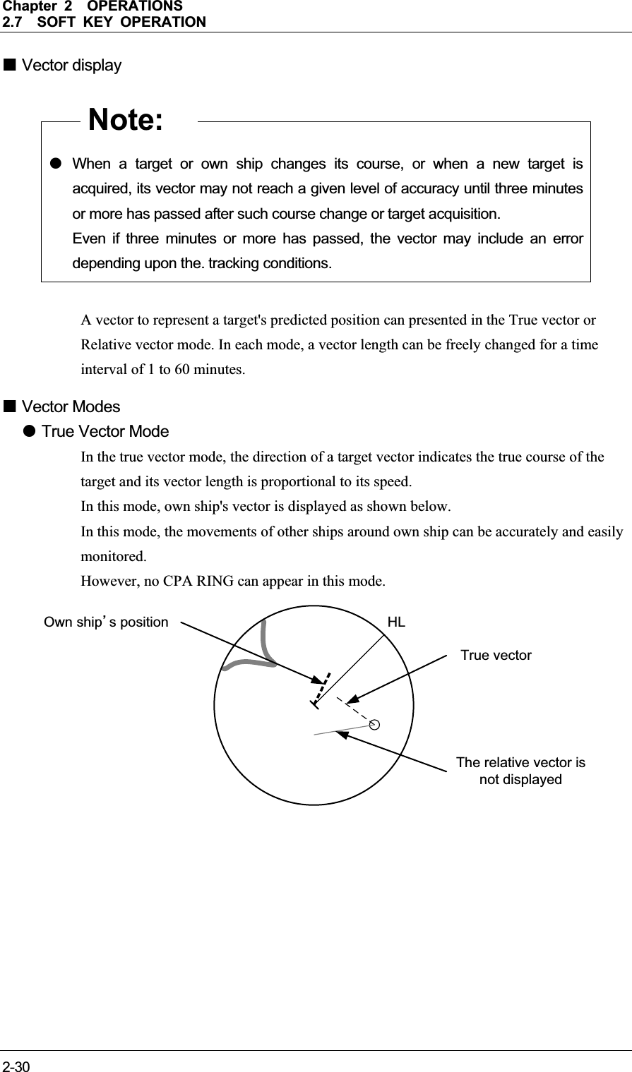
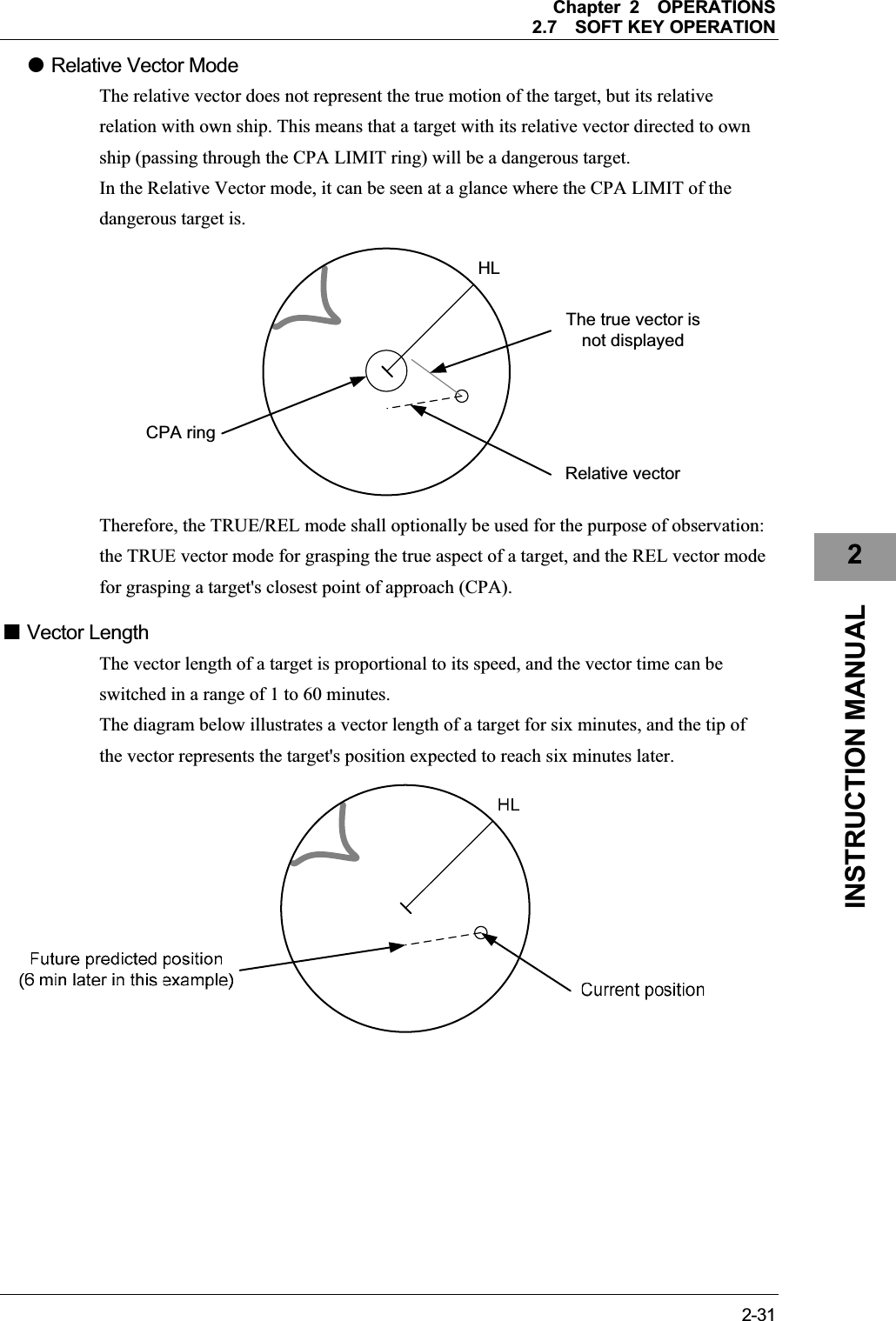
![Chapter 2OPERATIONS2.7SOFT KEY OPERATION 2-292INSTRUCTION MANUAL 2.7.4 SETTING VECTORS Sets TT and AIS vectors. Reference:The bearing and speed signal input are required to display TT and AIS vectors. 1Select Vector Length on the soft key menu. The soft key menu disappears and "Vector Length" of the soft key display is color-inverted."Vector Length" is activated. 2Operate with the soft keys. Soft key 1: True Relative Switches between true vector mode and relative vector mode. Soft key 2: Not available Soft key 3: Not available Soft key 4: Vector Length When "Vector Length" of the soft key menu is selected, "Vector Length" of the soft key display is color-inverted. Vector time can be set in minutes in the range 1 to 60 min. Turn the [MULTI] control to set the vector length. Reference:When "Vector Length" is not selected on the soft key menu, press the soft key 4 to activate the Vector Length function. Select "Vector Length" and press the control.](https://usermanual.wiki/Japan-Radio/NKE2043.Users-Manual-2/User-Guide-1634841-Page-29.png)
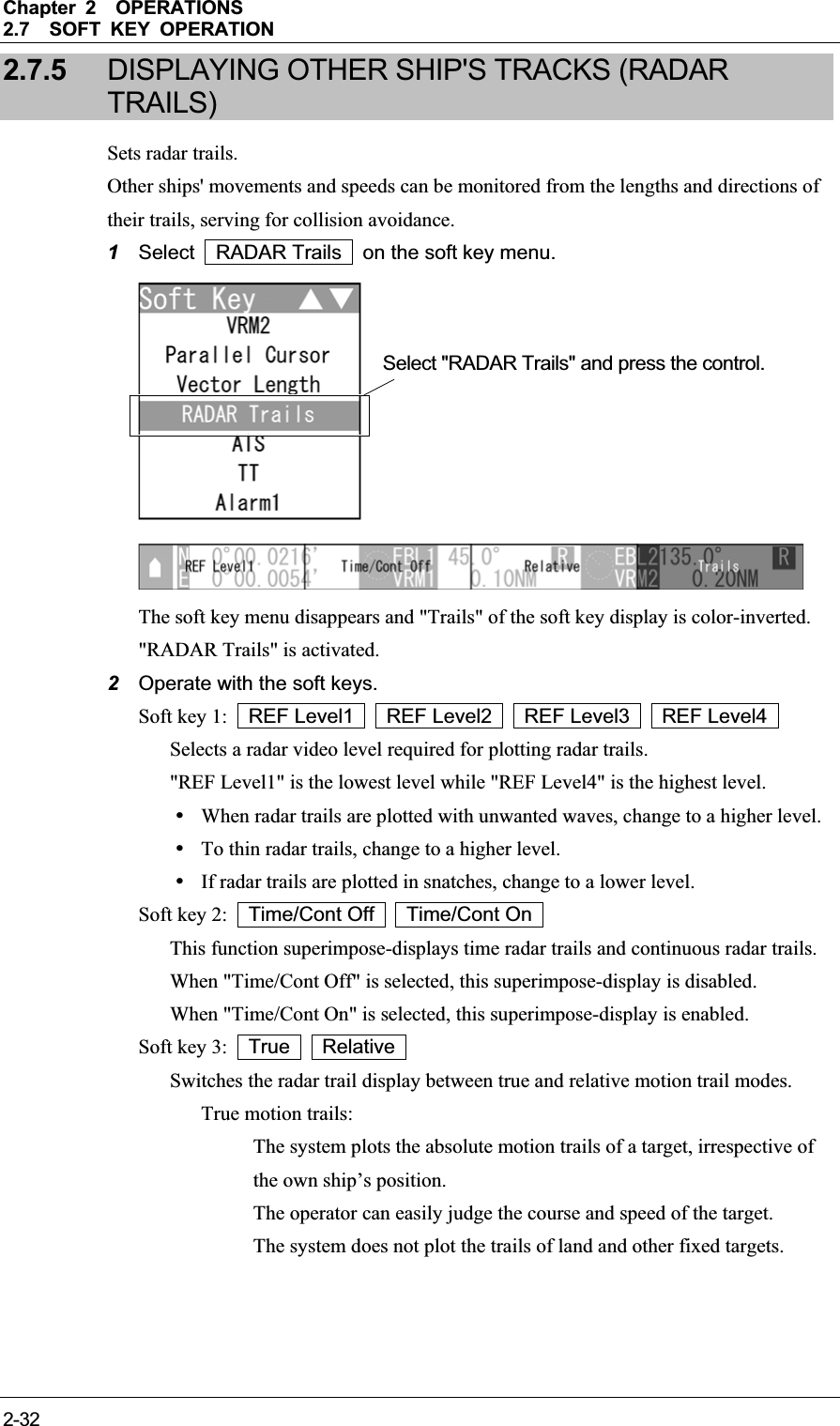
![Chapter 2OPERATIONS2.7SOFT KEY OPERATION 2-332INSTRUCTION MANUAL Relative motion trails: The system plots the trails of a target at a position relative to the own ship.The operator can easily judge whether the target is approaching the own ship. While the own ship is moving, the system also plots the trails when the own ship is turning. Reference:True bearing signal input and speed signal input are required to display radar trails in true motion trail mode. Soft key 4: Trails When "RADAR Trails" of the soft key menu is selected, "Trails" of the soft key display is color-inverted. Turn the [MULTI] control to change the radar trail length. Reference:When "RADAR Trails" is not selected on the soft key menu, press the soft key 4 to activate the RADAR Trails function. Short:Off/15sec/30sec/1min/2min/3min/4min/5min/6min/10min/15min/All Middle: Off/30sec/1min/2min/3min/4min/5min/6min/10min/15min/All Long: Off/1min/2min/3min/4min/5min/6min/10min/15min/30min/1hr/All Super Long: Off/30min/1hr/2hr/3hr/4hr/5hr/6hr/10hr/12hr/24hr/All To select the maximum time for displaying radar trails, see Section "2.10 RADAR TRAIL LENGTH SETTING")](https://usermanual.wiki/Japan-Radio/NKE2043.Users-Manual-2/User-Guide-1634841-Page-33.png)
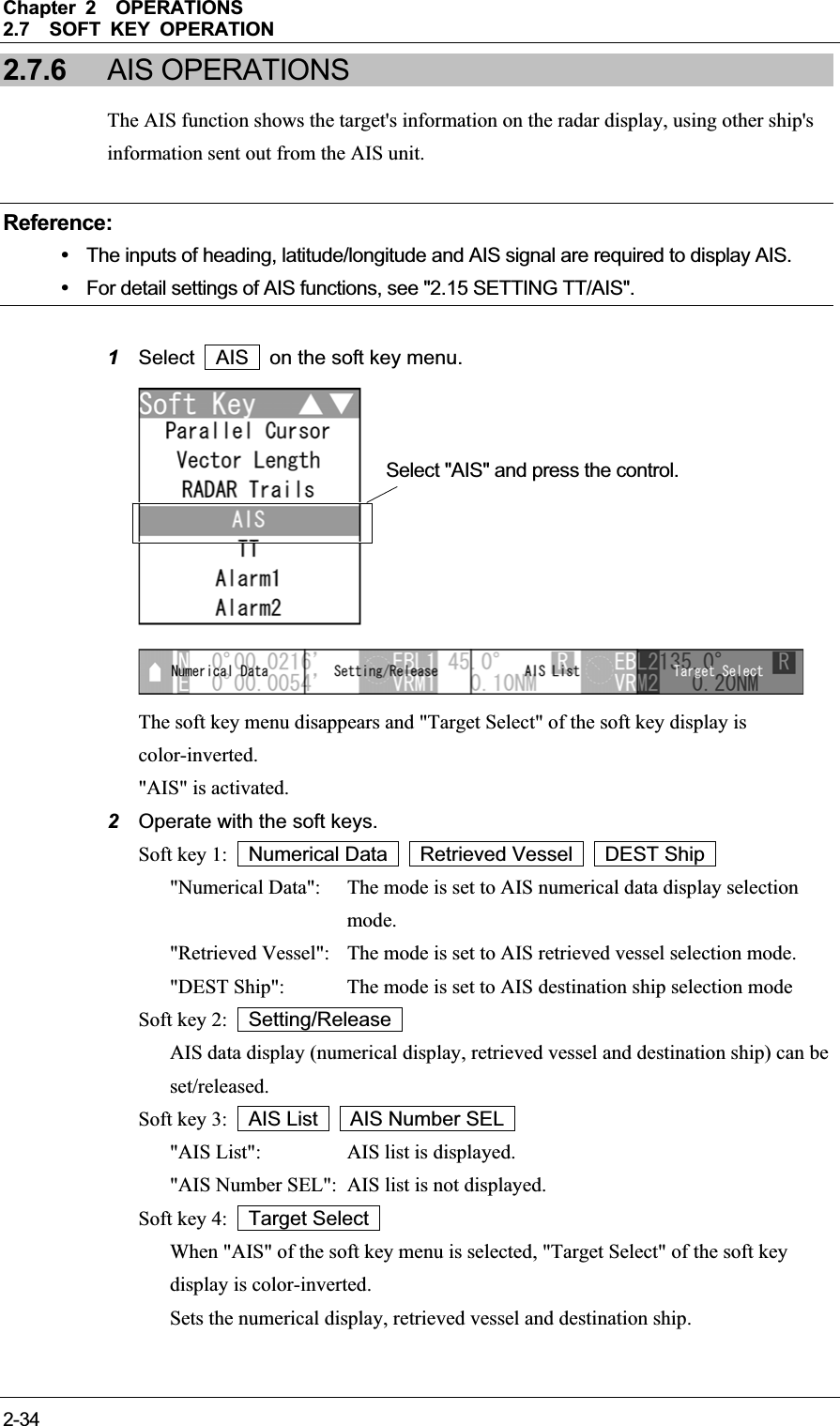
![Chapter 2OPERATIONS2.7SOFT KEY OPERATION 2-352INSTRUCTION MANUAL Reference:When "AIS" is not selected on the soft key menu, press the soft key 4 to activate the AIS function. AIS Retrieved Vessel AIS retrieved vessel is the function to preferentially display the user-specified ship. AIS Destination Ship AIS destination ship is the function to display the user-specified ship as the destination. AIS data (Numerical Data, Retrieved Vessel, DEST Ship) z Displaying AIS data (Operation with the soft key menu) 1Press the cursor keys to select "AIS", then press the [ENT] key. yWhen "Numerical Data" is displayed above the soft key 1 yWhen "Retrieved Vessel" is displayed above the soft key 1 yWhen "DEST Ship" is displayed above the soft key 1 The specified target data is displayed and the symbol is changed. The target data will remain on the radar display until the target is lost, or until another target is designated. Note: z Numerical Data, AIS retrieved vessel and AIS destination ship can be operated when Soft key 1: Numerical Data Retrieved Vessel DEST Ship are selected.](https://usermanual.wiki/Japan-Radio/NKE2043.Users-Manual-2/User-Guide-1634841-Page-35.png)
![Chapter 2OPERATIONS2.7SOFT KEY OPERATION 2-36z Displaying AIS data (Operation with the [ENT] key) AIS data (numerical display) can be done by the [ENT] key operation without displaying the soft key menu. 1Press the cursor keys to select "AIS", then press the [ENT] key. The selected AIS numerical display is set, and the "AIS" soft key is displayed. Note: z If operating with the [ENT] key when the soft key menu is closed, the equipment performs the followings: On the AIS symbol: Opens the AIS soft key and the numerical display of AIS. On the TT symbol: Opens the TT soft key and the numerical display of TT. Not on the AIS or TT symbol: Opens the TT soft key, it will be acquired. z If operating with the [ENT] key when the AIS symbol overlaps the TT symbol, the numerical display of AIS symbol takes priority. Reference:y After setting the AIS numerical display, perform the same operations in "ە Displaying AIS data (Operation with the soft key menu)". y AIS data (numerical data) is displayed when the soft key 4 is set to "AIS Detail" in the section "2.7.11 SETTING DISPLAY SCREEN". z Releasing AIS data display 1Press the cursor keys to select "AIS", then press the [ENT] key. Numerical Data, AIS retrieved vessel and AIS destination ship are canceled.](https://usermanual.wiki/Japan-Radio/NKE2043.Users-Manual-2/User-Guide-1634841-Page-36.png)
![Chapter 2OPERATIONS2.7SOFT KEY OPERATION 2-372INSTRUCTION MANUAL Displaying the other AIS data Reference:y AIS retrieved vessel can be set by specifying MMSI number. For details of settings, see "2.15.8 SETTING AIS RETRIEVED VESSEL". y AIS destination ship can be set by specifying MMSI number. For details of settings, see "2.15.7 SETTING AIS DESTINATION SHIP". z Displaying AIS data 1Turn the [MULTI] control to select "AIS", then press the soft key 3 "Setting/Release".yWhen "Numerical Data" is displayed above the soft key 1 yWhen "Retrieved Vessel" is displayed above the soft key 1 yWhen "DEST Ship" is displayed above the soft key 1 The specified target data is displayed and the symbol is changed. The target data will remain on the radar display until the target is lost, or until another target is designated. When the target for the numerical display is set, "#" is displayed in the AIS list. "#" disappears when the target is released.](https://usermanual.wiki/Japan-Radio/NKE2043.Users-Manual-2/User-Guide-1634841-Page-37.png)
![Chapter 2OPERATIONS2.7SOFT KEY OPERATION 2-38When the AIS retrieved vessel is set, "*" is displayed in the AIS list. "*" disappears when it is released. When the AIS destination ship is set, "$" is displayed in the AIS list. "$" disappears when it is released. Reference:AIS data (Numerical Data) is displayed when the soft key 4 is set to "AIS Detail" in the section "2.7.11 SETTING DISPLAY SCREEN" Note: z Numerical Data, AIS retrieved vessel and AIS destination ship can be operated when Soft key 1: Numerical Data Retrieved Vessel DEST Ship are selected. z Releasing AIS data display 1Turn the [MULTI] control to select "AIS", then press the soft key 3 "Setting/Release".Numerical Data, AIS retrieved vessel and AIS destination ship are canceled. AIS Symbols This section describes types and definitions of AIS symbols. Symbol Definition Remarks Activated AIS target This symbol shows the position of an AIS target on the PPI. The shape is an isosceles triangle, and its vertex shows the approximate heading direction. If heading bearing information or COG information is not received, the target is displayed toward PPI. Selection When selecting an AIS target to display its numeric information, this symbol is superimpose-displayed on the selected target. This is displayed with a split square (basic color is white). AIS SART This symbol shows the position of an AIS SART target on the PPI.This is displayed with a circle and cross lines.](https://usermanual.wiki/Japan-Radio/NKE2043.Users-Manual-2/User-Guide-1634841-Page-38.png)
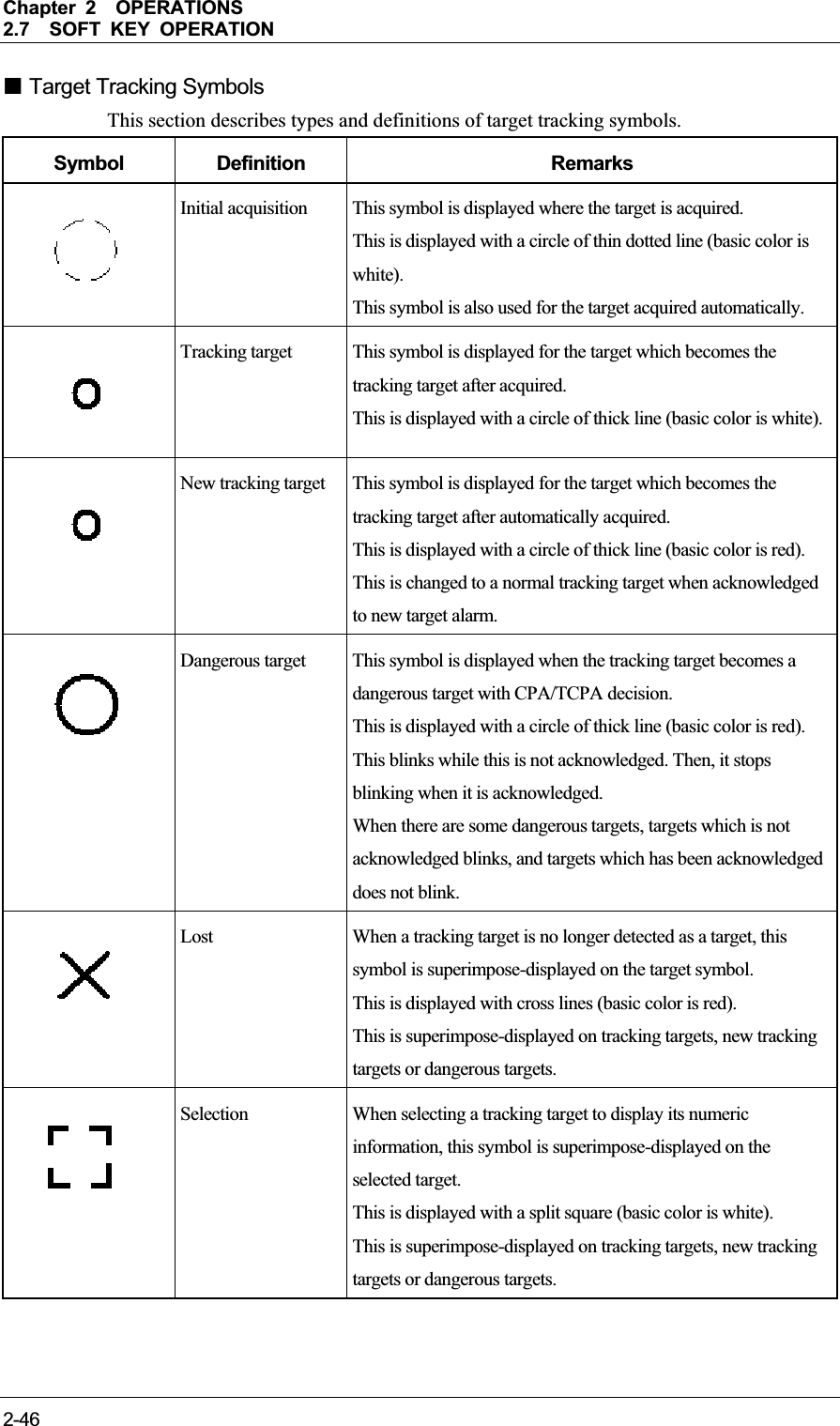
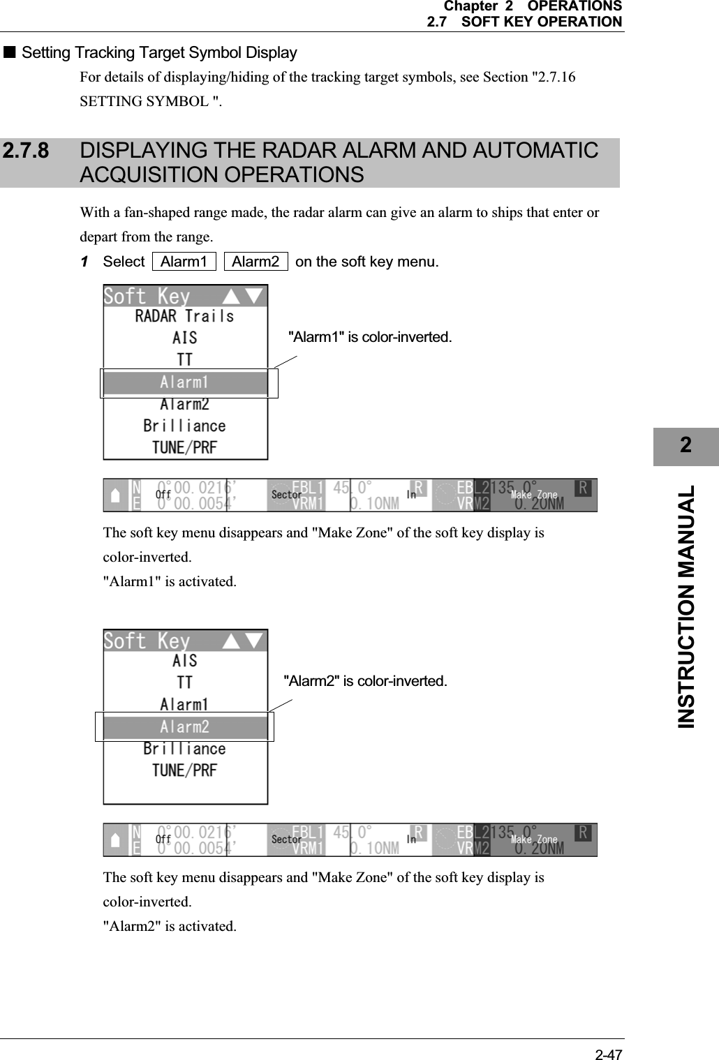
![Chapter 2OPERATIONS2.7SOFT KEY OPERATION 2-392INSTRUCTION MANUAL Setting AIS Symbol Display For details of displaying/hiding of the AIS symbols, see Section "2.7.16 SETTING SYMBOL ". 2.7.7 TT OPERATIONS The target tracking function calculates the course and speed of a target by automatically tracking the target's move. Note: z There are the following limitations on use of the target acquisition and target tracking functions. [I] Resolution between adjacent targets and swapping during automatic target tracking Depending on the particular distance and echo size, resolution between adjacent targets during automatic target tracking usually ranges somewhere between 0.03 to 0.05 NM. If multiple targets approach each other, resolution will become about 0.05 NM and this may cause the system to regard them as one target and thus to swap them or lose part of them. Such swapping or less of targets may also occur if the picture of the target being tracked is affected by rain/snow clutter returns or sea clutter returns or moves very close to land. [II] Intensity of echoes and the target tracking function The intensity of echoes and the tracking function have a correlationship, and thus the target will be lost if no echoes are detected during seven scans in succession. If a lost target exists, therefore, radar gain must be increased to support detection of the target. If, however, radar gain is increased too significantly, sea clutter returns or other noise may be erroneously detected and tracked as a target, and resultingly, a false alarm may be issued. To execute accurate tracking, it becomes necessary to appropriately adjust the [GAIN], [SEA] and [RAIN] controls of the radar so that the target to be acquired and tracked id clearly displayed on the radar display. Inappropriate settings of these adjustments reduce the reliability / accuracy of automatic tracking.](https://usermanual.wiki/Japan-Radio/NKE2043.Users-Manual-2/User-Guide-1634841-Page-39.png)
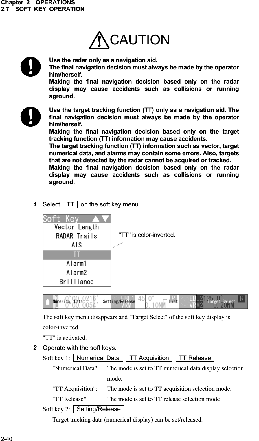
![Chapter 2OPERATIONS2.7SOFT KEY OPERATION 2-412INSTRUCTION MANUAL Soft key 3: TT List TT Number SEL "TT List": TT list is displayed. "TT Number SEL": TT list is not displayed. Soft key 4: Target Select When "TT" of the soft key menu is selected, "Target Select" of the soft key display is color-inverted. Sets the numerical display, TT acquisition and TT release. Reference:When "TT" is not selected on the soft key menu, press the soft key 4 to activate the TT function. Target acquisition This equipment has automatic acquisition and manual acquisition. z Manual acquisition (Operation with the soft key menu) Note: z Manual acquisition can be operated when Soft key 1: TT Acquisition are selected. z If the range is switched, the acquisitions of targets acquired before switching the range are released when those targets get out of the echo radius. 1Press the cursor keys to select the target for acquisition with the cursor, then press the [ENT] key. An initial acquisition symbol appears. After one minute elapses, the target tracking symbol and vector are displayed.](https://usermanual.wiki/Japan-Radio/NKE2043.Users-Manual-2/User-Guide-1634841-Page-41.png)
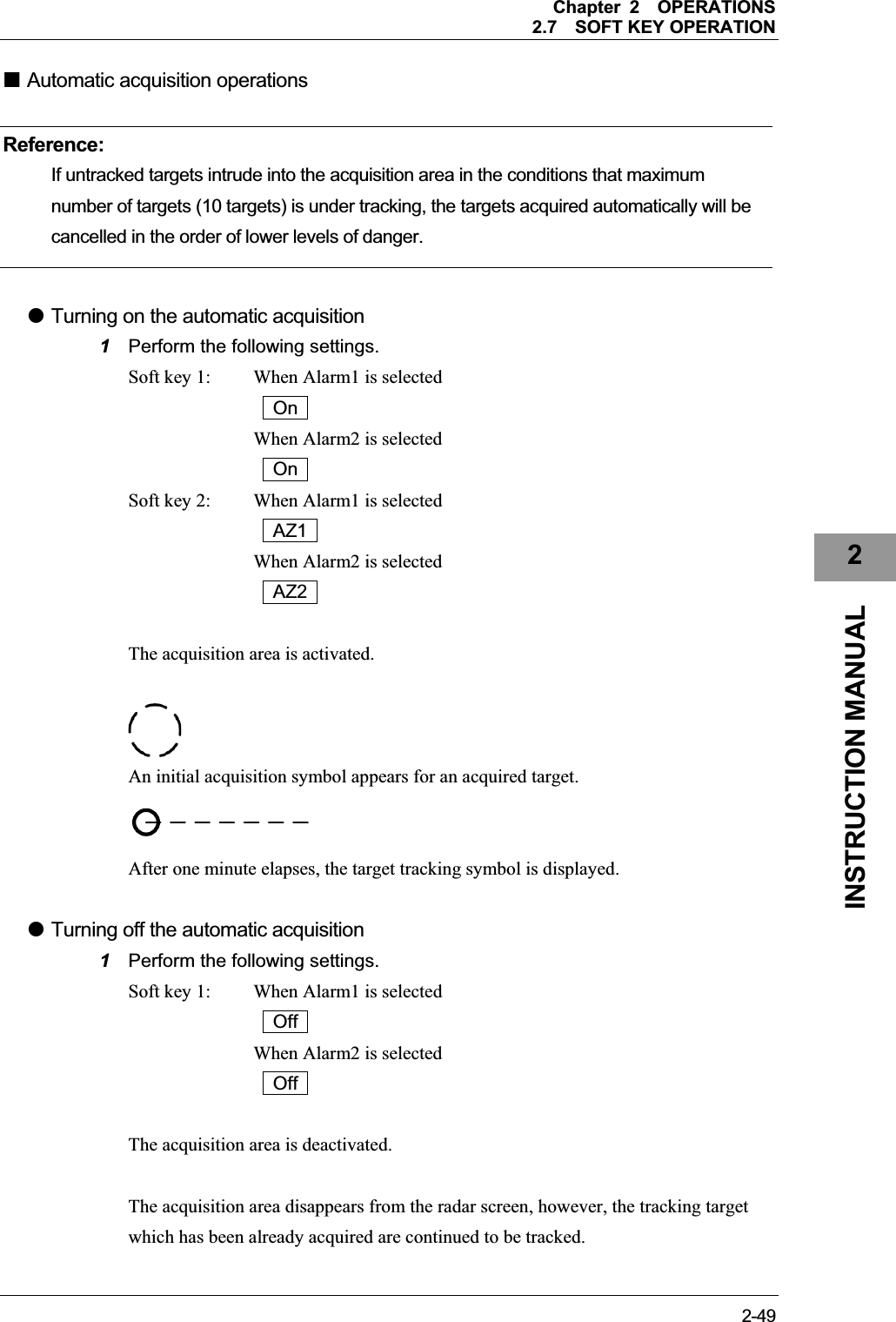
![Chapter 2OPERATIONS2.7SOFT KEY OPERATION 2-42Reference:When the number of targets tracked has reached to the maximum (10 targets), any new target is not acquired. Delete the unnecessary targets, then acquire new targets. z Manual acquisition (Operation with the [ENT] key) Target can be acquired by the [ENT] key operation without displaying the soft key menu. Note: z If operating with the [ENT] key when the soft key menu is closed, the equipment performs the followings: On the AIS symbol: Opens the AIS soft key and the numerical display of AIS. On the TT symbol: Opens the TT soft key and the numerical display of TT. Not on the AIS or TT symbol: Opens the TT soft key, it will be acquired. z If operating with the [ENT] key when the AIS symbol overlaps the TT symbol, the numerical display of AIS symbol takes priority. 1Press the cursor keys to select the target for acquisition with the cursor, then press the [ENT] key. An initial acquisition symbol appears, and the "TT" soft key is displayed. After one minute elapses, the target tracking symbol and vector are displayed. Reference:y When operating the [ENT] key on a TT symbol, the "TT" soft key and the target tracking data are displayed. y When operating the [ENT] key on an AIS symbol, the "AIS" soft key and the selected AIS data (numerical display) are displayed. z Automatic acquisition 1Perform the procedure as shown below to start automatic acquisition. Open Alarm1 from the soft key menu. Soft key 1: On Soft key 2: AZ1](https://usermanual.wiki/Japan-Radio/NKE2043.Users-Manual-2/User-Guide-1634841-Page-42.png)
![Chapter 2OPERATIONS2.7SOFT KEY OPERATION 2-432INSTRUCTION MANUAL Reference:y If untracked targets intrude into the automatic acquisition area in the conditions that maximum number of targets (10 targets) is under tracking, the targets acquired automatically will be cancelled in the order of lower levels of danger. y For details of automatic acquisition operation, refer to "2.7.8 DISPLAYING THE RADAR ALARM AND AUTOMATIC ACQUISITION OPERATIONS". Deleting the unnecessary targets Note: z Releasing manual acquisition can be operated when Soft key 1: TT Release are selected. 1Press the cursor keys to select the target for releasing with the cursor, then press the [ENT] key. The target's vectors and symbols disappear, and only the radar video remains. Target tracking data (numerical display) Note: z The numerical display can be operated when Soft key 1: Numerical Data are selected. z Displaying tracking target data (Operation with the soft key menu) 1Press the cursor keys to select the target for the numerical display with the cursor, then press the [ENT] key. The specified target data is displayed and the symbol is changed. The target data will remain on the radar display until the target is lost and its vector disappears, or until another target is designated.](https://usermanual.wiki/Japan-Radio/NKE2043.Users-Manual-2/User-Guide-1634841-Page-43.png)
![Chapter 2OPERATIONS2.7SOFT KEY OPERATION 2-44Reference:y If a target with the mark “ۑ” is designated, only its true bearing and range will appear until its vector appears. y Tracking target data is displayed when the soft key 4 is set to "TT Detail" in the section "2.7.11 SETTING DISPLAY SCREEN" z Displaying tracking target data (Operation with the [ENT] key) The target tracking data can be displayed by the [ENT] key operation without displaying the soft key menu. Note: z If operating with the [ENT] key when the soft key menu is closed, the equipment performs the followings: On the AIS symbol: Opens the AIS soft key and the numerical display of AIS. On the TT symbol: Opens the TT soft key and the numerical display of TT. Not on the AIS or TT symbol: Opens the TT soft key, it will be acquired. z If operating with the [ENT] key when the AIS symbol overlaps the TT symbol, the numerical display of AIS symbol takes priority. 1Press the cursor keys to select the target for numerical display with the cursor, then press the [ENT] key. The selected target tracking numerical display is set, and the "TT" soft key is displayed. Reference:After setting the TT numerical display, perform the same operations in "ە Displaying tracking target data (Operation with the soft key menu)". z Releasing tracking target data display 1Press the cursor keys to select the target for the numerical display with the cursor, then press the [ENT] key. Numerical data display is released.](https://usermanual.wiki/Japan-Radio/NKE2043.Users-Manual-2/User-Guide-1634841-Page-44.png)
![Chapter 2OPERATIONS2.7SOFT KEY OPERATION 2-452INSTRUCTION MANUAL Displaying the other tracking target data Note: z The numerical display can be operated when Soft key 4: Target Select are selected. z Displaying tracking target data 1Turn the [MULTI] control to select the target for the numerical display, then press the soft key 3 "Setting/Release". The specified target data is displayed and the symbol is changed. The target data will remain on the radar display until the target is lost and its vector disappears, or until another target is designated. When the target for the numerical display is set, "#" is displayed in the TT list. "#" disappears when the target is released. Reference:y If a target with the mark “ۑ” is designated, only its true bearing and range will appear until its vector appears. y Tracking target data is displayed when the soft key 4 is set to "TT Detail" in the section "2.7.11 SETTING DISPLAY SCREEN". z Releasing tracking target data display 1Turn the [MULTI] control to select the target for the numerical display, then press the soft key 3 "Setting/Release". Numerical data display is released.](https://usermanual.wiki/Japan-Radio/NKE2043.Users-Manual-2/User-Guide-1634841-Page-45.png)
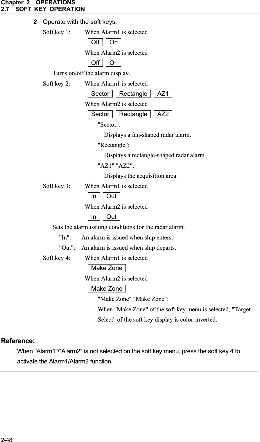
![Chapter 2OPERATIONS2.7SOFT KEY OPERATION 2-50 Creating a fan-shaped radar alarm/acquisition area 1Perform the following settings. Soft key 2: When Alarm1 is selected Sector AZ1 When Alarm2 is selected Sector AZ2 The range setting is started for a fan-shaped radar alarm/acquisition area. 2Press the cursor keys to move the cursor to the first point (setting of the start bearing and range), then press the [ENT] key. 3Press the cursor keys to move the cursor to the second point (setting of the end range), then press the [ENT] key. ](https://usermanual.wiki/Japan-Radio/NKE2043.Users-Manual-2/User-Guide-1634841-Page-50.png)
![Chapter 2OPERATIONS2.7SOFT KEY OPERATION 2-512INSTRUCTION MANUAL 4Press the cursor keys to move the cursor to the third point (setting of the end bearing), then press the [ENT] key. 5A fan-shaped radar alarm/acquisition area is determined. Reference:After the fan-shaped radar alarm/acquisition area is determined, the soft key menu and the soft key display disappears, and Alarm1 function is terminated. Creating a rectangle-shaped radar alarm 1Perform the following settings. Soft key 2: When Alarm1 is selected Rectangle When Alarm2 is selected Rectangle The range setting is started for a rectangle-shaped radar alarm.](https://usermanual.wiki/Japan-Radio/NKE2043.Users-Manual-2/User-Guide-1634841-Page-51.png)
![Chapter 2OPERATIONS2.7SOFT KEY OPERATION 2-522Press the cursor keys to move the cursor to the first point (setting of the start latitude and longitude), then press the [ENT] key. 3Press the cursor keys to move the cursor to the second point (setting of the end latitude), then press the [ENT] key. 4Press the cursor keys to move the cursor to the third point (setting of the end latitude), then press the [ENT] key. ](https://usermanual.wiki/Japan-Radio/NKE2043.Users-Manual-2/User-Guide-1634841-Page-52.png)
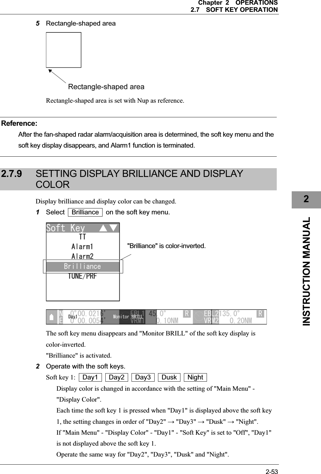
![Chapter 2OPERATIONS2.7SOFT KEY OPERATION 2-54Soft key 2: Monitor BRILL When "Brilliance" of the soft key menu is selected, "Monitor BRILL" of the soft key display is color-inverted. Press the [BRILL] key to adjust at eight levels. Also, you can turn the [MULTI] control to change the level. Soft key 3: Not available Soft key 4: Not available Reference:When "Brilliance" is not selected on the soft key menu, press the soft key 4 to activate the Brilliance function. 2.7.10 ADJUSTING SCANNER There are automatic tuning mode (AUTO) and manual tuning mode (MAN). In the automatic tuning mode, transmission and receiving frequencies are tuned and adjusted automatically. In the manual tuning mode, tuning is carried out using the MULTI control.1Select TUNE/PRF on the soft key menu. The "TUNE/PRF" soft key display appears. 2Operate with the soft keys. Soft key 1: AUTO Tune Manual Tune Selects whether to use the tuning function in automatic or manual mode. "TUNE/PRF" is color-inverted.](https://usermanual.wiki/Japan-Radio/NKE2043.Users-Manual-2/User-Guide-1634841-Page-54.png)
![Chapter 2OPERATIONS2.7SOFT KEY OPERATION 2-552INSTRUCTION MANUAL Soft key 2: Manual Tuning When pressing the soft key 2, "Manual Tuning" is color-inverted. yWhen "MAN" is displayed above the soft key 1 You can manually adjust using the MULTI control. Turn the MULTI control to adjust tuning. Adjust the video to be the largest by observing the tune indicator bar. Because the tune indicator bar is the guide during manual tuning, adjust the tune indicator bar to the maximum. yWhen "AUTO" is displayed above the soft key 1 "Manual Tuning" is not color-inverted. The equipment automatically adjust tuning. Tuning is adjusted when transmission is started, the range is changed or pulse length is changed. Soft key 3: PRF Fine Tuning When pressing the soft key 3, "PRF Fine Tuning" is color-inverted. The PRF fine tuning screen appears. Fine-tune the transmitting repetition frequency of the transmitter in the range 90 to 100%. If radar's interference patterns are concentrically displayed, increment or decrement the set value by 3 to 4 in order to heighten the effect of interference rejection.The same operation can be performed by pressing the [TX/PRF] key several times. Use the [MULTI] control to perform PRF fine tuning between 0 and 31. When the soft key 3 "PRF Fine Tuning" is pressed, color-inverted display returns to normal color. Soft key 4: Not available Tune indicator bar](https://usermanual.wiki/Japan-Radio/NKE2043.Users-Manual-2/User-Guide-1634841-Page-55.png)
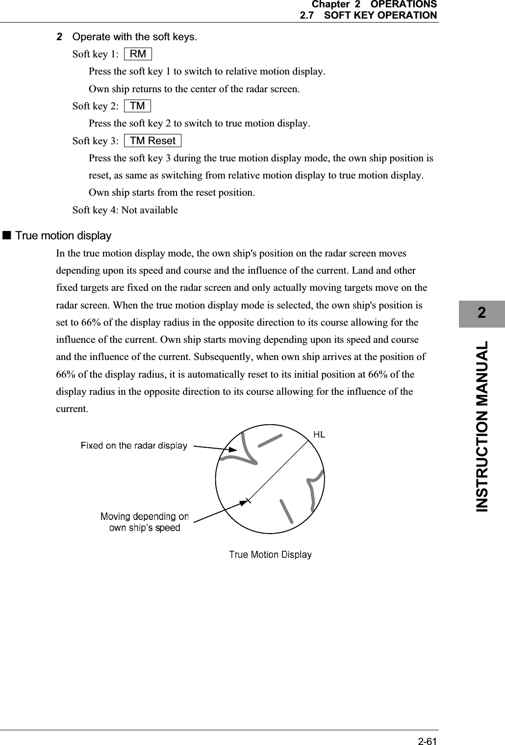
![Chapter 2OPERATIONS2.7SOFT KEY OPERATION 2-60 Hiding the heading line 1Hold down the [TX/PRF] key. The ship's heading line is hidden while the [TX/PRF] key is held down. The ship's heading line (HL) that presents the course of own ship is always shown on the radar display. The heading line is hidden while the [TX/PRF] key is held down, so the targets on the heading line can be easily observed. 2.7.12 SWITCHING TO TRUE/RELATIVE MOTION DISPLAY MODESwitches between true and relative motion display modes. Reference:The bearing signal input is required to display true motion. 1Select TM/RM on the soft key menu. The "TM/RM" soft key display appears. "TM/RM" is color-inverted.](https://usermanual.wiki/Japan-Radio/NKE2043.Users-Manual-2/User-Guide-1634841-Page-60.png)
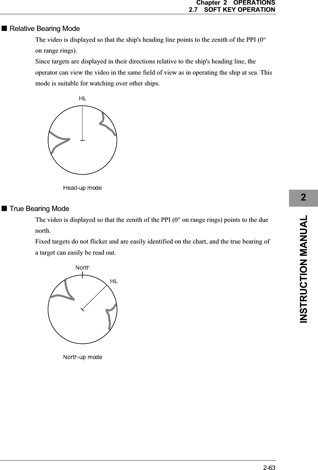
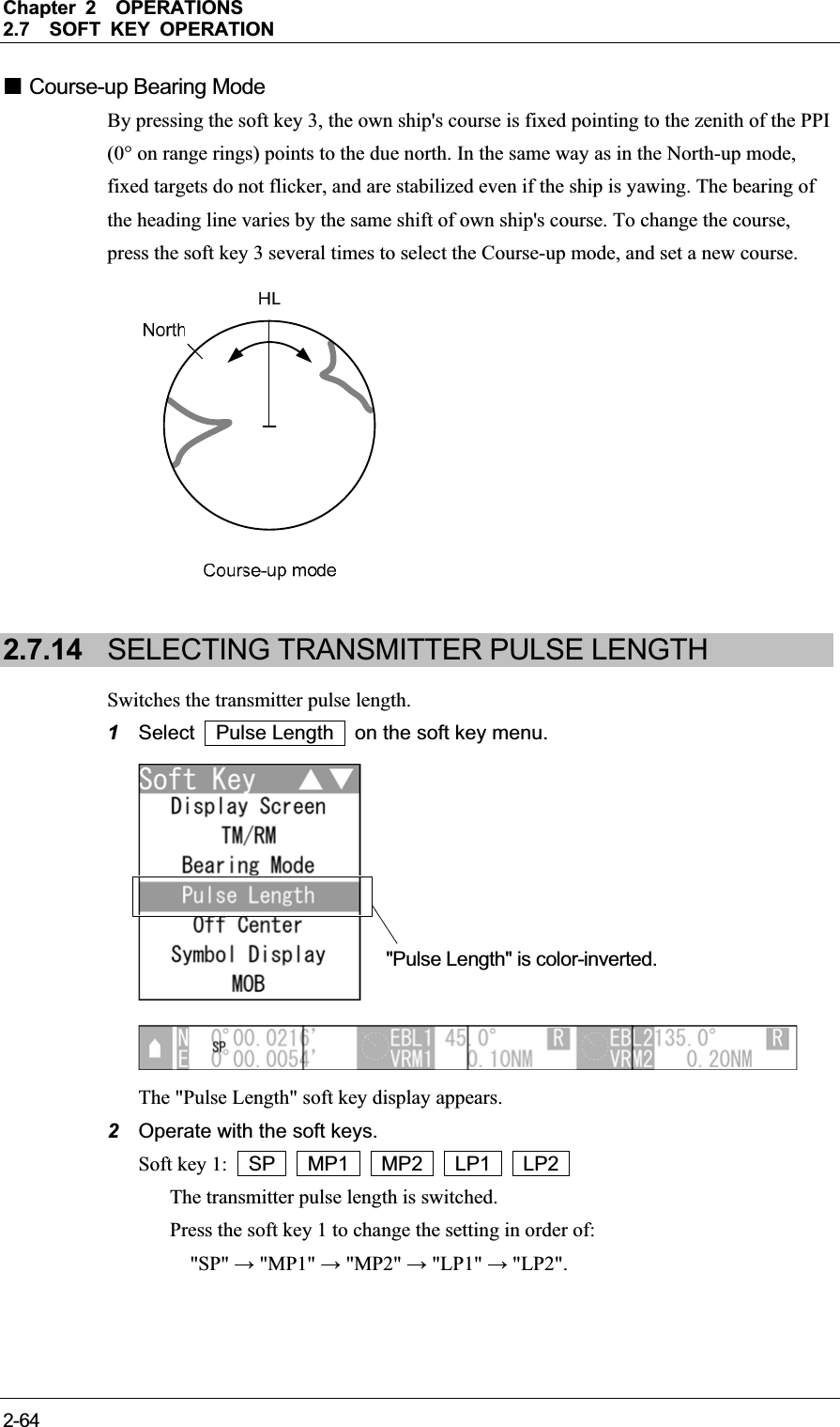
![Chapter 2OPERATIONS2.7SOFT KEY OPERATION 2-622.7.13 SWITCHING BEARING DISPLAY MODE Selects the azimuth of the radar video. Reference:The bearing signal input is required to display N Up/C Up. 1Select Bearing Mode on the soft key menu. The "Bearing Mode" soft key display appears. 2Operate with the soft keys. Soft key 1: H Up Relative bearing mode [Head Up] is selected. Soft key 2: N Up True bearing mode [North Up] is selected. Soft key 3: C Up Course-up bearing mode [Course Up] is selected. Soft key 4: C Up Reset In Course-up mode, reset the course-up display. "Bearing Mode" is color-inverted.](https://usermanual.wiki/Japan-Radio/NKE2043.Users-Manual-2/User-Guide-1634841-Page-62.png)
![Chapter 2OPERATIONS2.7SOFT KEY OPERATION 2-692INSTRUCTION MANUAL 1Select Mark on the soft key menu. The "Mark" soft key display appears. 2Operate with the soft keys. Soft key 1: X + Y The mark type of a target is changed. For details of size setting, see "2.17.2 SETTING MARK FUNCTIONS". Soft key 2: White Cyan Blue Green Yellow Pink Red The mark color of a target is changed. Soft key 3: Delete Press to delete the marks of selected type/color. Hold down to delete all marks. The confirmation dialog window is displayed. (Marks and event marks are not distinguished when deleting.) Soft key 4: Off Enter Erase Move You can use the [ENT] key to create/delete/move the marks. "Enter": Press the [ENT] key to create a mark at the cursor position. "Erase": Press the [ENT] key to delete a mark at the cursor position. "Move": Use the cursor to select the mark to be moved and press the [ENT]key. Then move the cursor to select the new position and press the [ENT] key to place the mark. "Mark" is color-inverted.](https://usermanual.wiki/Japan-Radio/NKE2043.Users-Manual-2/User-Guide-1634841-Page-69.png)
![Chapter 2OPERATIONS2.7SOFT KEY OPERATION 2-702.7.19 USING LINES Lines can be indicated at arbitrary positions on the screen. Reference:y Bearing signal input and latitude/longitude data input are required to use lines. y Up to 200 lines/marks can be displayed for lines, marks and event marks in total. 1Select Line on the soft key menu. The "Line" soft key display appears. 2Operate with the soft keys. Soft key 1: ̿̿ - - - - The line type of a target is changed. Soft key 2: White Cyan Blue Green Yellow Pink Red The line color of a target is changed. Soft key 3: Delete Press to delete the lines of selected type/color. Hold down to delete all lines. The confirmation dialog window is displayed. Soft key 4: Off Enter Erase Move Insert You can use the [ENT] key to create/delete/move the lines. "Enter": Press the [ENT] key to create a line at the cursor position. "Erase": Press the [ENT] key to delete a line at the cursor position. "Move": Use the cursor to select the line to be moved and press the [ENT] key. Then move the cursor to select the new position and press the [ENT]key to place the line. "Insert”: Use the cursor to select the line to be inserted and press the [ENT] key. Then move the cursor to select the position and press the [ENT] key to insert the line. "Line" is color-inverted.](https://usermanual.wiki/Japan-Radio/NKE2043.Users-Manual-2/User-Guide-1634841-Page-70.png)
![Chapter 2OPERATIONS2.7SOFT KEY OPERATION 2-732INSTRUCTION MANUAL 2.7.22 SETTING AIS FILTER Once the AIS filter is set, only the AIS targets that are inside the filter area are displayed (setting can be made such that AIS targets outside the AIS filter will not be shown). The filter is initially set in a circle having a radius of 20 [NM] from the own ship's position. If 50 or more targets exist in the filter range, they are displayed according to the priority explained in "■ AIS Symbols" of Section "2.7.6 AIS OPERATIONS". Reference:y Bearing signal input and latitude/longitude data input are required to use AIS functions. y This function is initially set to off. To use this function, set this to on by referring to "ڦ Soft Key Menu Setting" in "4.10 Control" of the Installation Manual. 1Select AIS Filter on the soft key menu. The "AIS Filter" soft key display appears. 2Operate with the soft keys. Soft key 1: Off Range Switches between Off and Range.. "Range": A filter is set in a circle with a set range as the radius. Soft key 2: Off On "Off": The filter is not displayed. "On": The filter is displayed. "AIS Filter" is color-inverted.](https://usermanual.wiki/Japan-Radio/NKE2043.Users-Manual-2/User-Guide-1634841-Page-73.png)
![Chapter 2OPERATIONS2.7SOFT KEY OPERATION 2-742.7.23 USING TLL TX Reference:This function is initially set to off. To use this function, set this to on by referring to "ڦ Soft Key Menu Setting" in "4.10 Control" of the Installation Manual. Sets the TLL TX. Transmits the TLL sentence of the cursor position on the screen to inform the mark position.1Select TLL TX on the soft key menu. The "TLL TX" soft key display appears. 2Operate with the soft keys. Soft key 1: Off TLL TX "Off": TLL sentence is not transmitted with the [ENT] key. "TLL TX": TLL sentence of the cursor position is transmitted with the [ENT]key. Soft key 2: Not available Soft key 3: Not available Soft key 4: Not available "TLL TX" is color-inverted.](https://usermanual.wiki/Japan-Radio/NKE2043.Users-Manual-2/User-Guide-1634841-Page-74.png)
![Chapter 2OPERATIONS2.8BASIC MENU OPERATIONS 2-752INSTRUCTION MANUAL 2.8 BASIC MENU OPERATIONS The settings which will not be frequently changed are called by the [MENU] key. This section describes the operation with the MENU key. Keys for operation y [MENU] key yCursor keys y [MULTI] control y [CLEAR] key z [CLEAR] key Press the [CLEAR] key to return to the upper level. MENU Key Operations (Example: Opening "IR") 1Press the [MENU] key. Select one of the menu items with ">" mark, then press the [ENT] key or the cursor key (right) to display the submenu.](https://usermanual.wiki/Japan-Radio/NKE2043.Users-Manual-2/User-Guide-1634841-Page-75.png)
![Chapter 2OPERATIONS2.8BASIC MENU OPERATIONS 2-762Press the cursor key (down) or turn the [MULTI] control (clockwise) to select RADAR Echo . 3Press the [ENT] key, the cursor key (right) or the [MULTI] control. "RADAR Echo" menu appears. Current settings are displayed on the right pane of the menu. "RADAR Echo" is color-inverted.](https://usermanual.wiki/Japan-Radio/NKE2043.Users-Manual-2/User-Guide-1634841-Page-76.png)