Japan Radio NKE2044 MARINE RADAR User Manual 3
Japan Radio Co Ltd. MARINE RADAR 3
UserManual.wiki
>
Japan Radio
>
NKE2044 User Manual
>
User Manual 3
Contents
1.
User Manual 1
2.
User Manual 2
3.
User Manual 3
4.
User Manual 4
5.
User Manual 5
User Manual 3
Navigation menu
Upload a User Manual
Namespaces
Wiki Guide
HTML
PDF
Info
Views
User Manual
Discussion / Help
Navigation
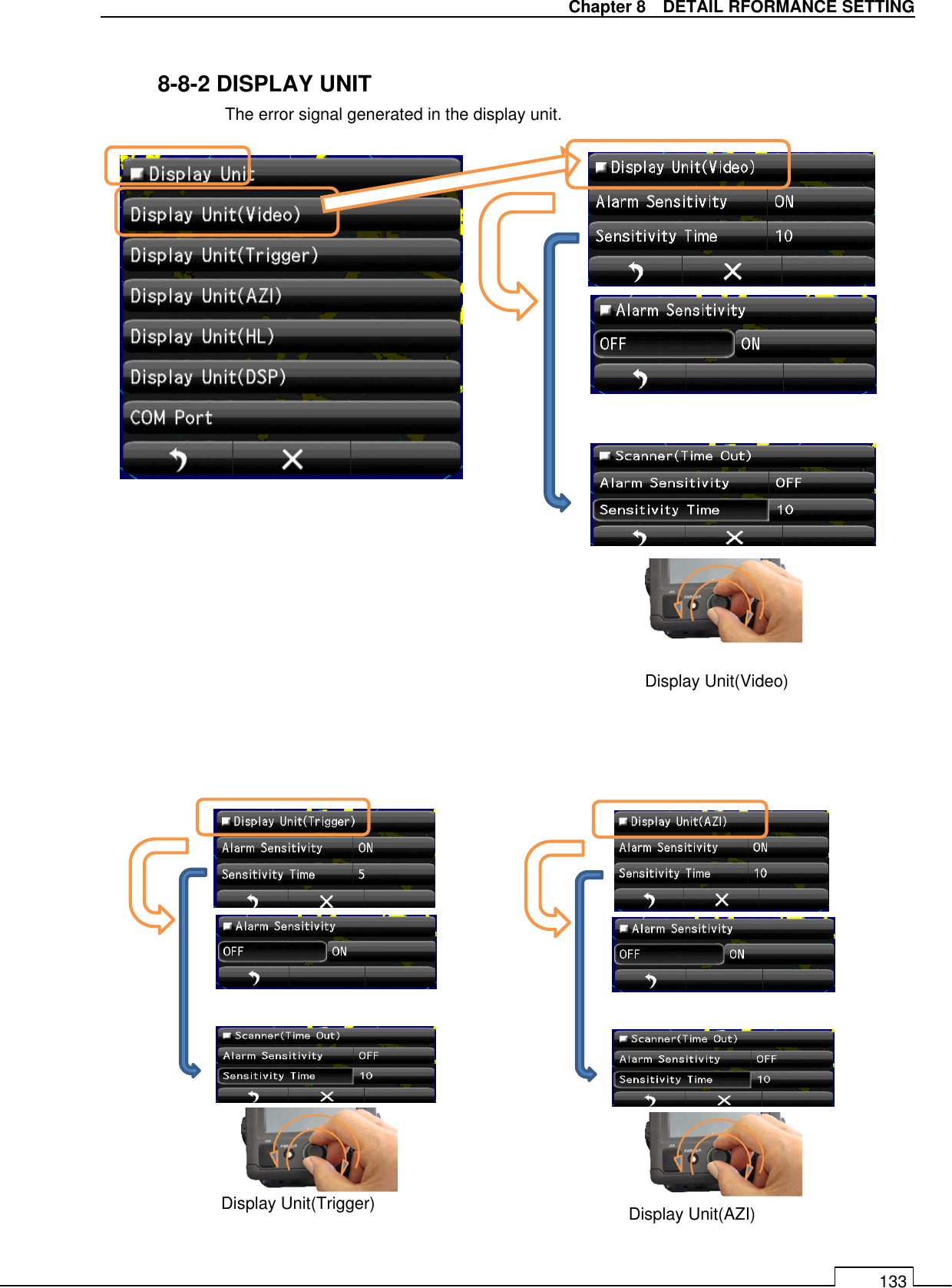
![Chapter 8 DETAIL PERFORMANCE SETTING 134 ] Display Unit(HL) Display Unit(DSP) COM Port](https://usermanual.wiki/Japan-Radio/NKE2044.User-Manual-3/User-Guide-2182310-Page-36.png)