Japan Radio NKE2103 Marine Radar User Manual
Japan Radio Co Ltd. Marine Radar Users Manual
UserManual.wiki
>
Japan Radio
>
NKE2103 User Manual
>
Users Manual 1
Contents
1.
Users Manual 1
2.
Users Manual 2
3.
Users Manual 3
4.
Users Manual
Users Manual 1
Navigation menu
Upload a User Manual
Namespaces
Wiki Guide
HTML
PDF
Info
Views
User Manual
Discussion / Help
Navigation
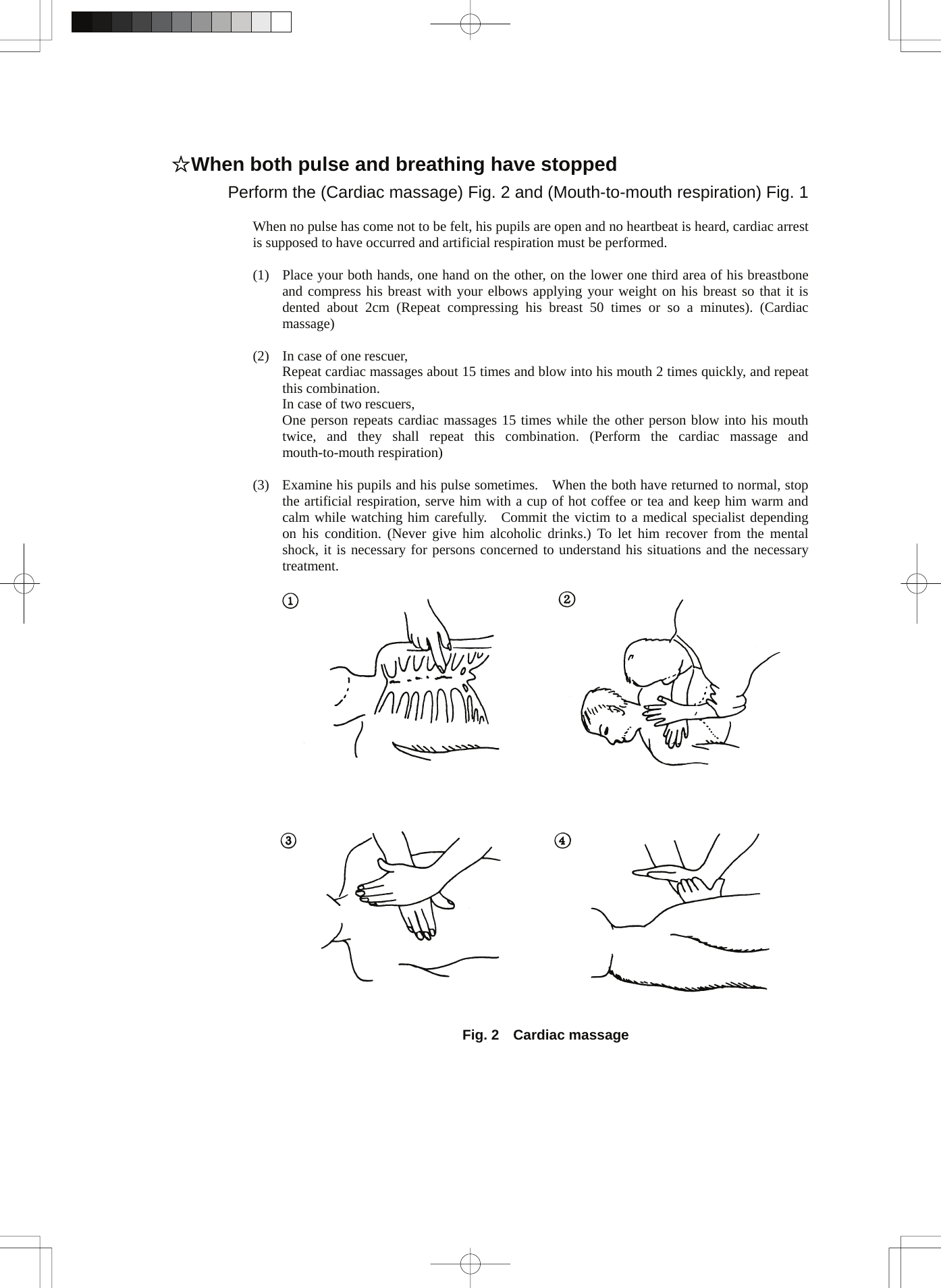
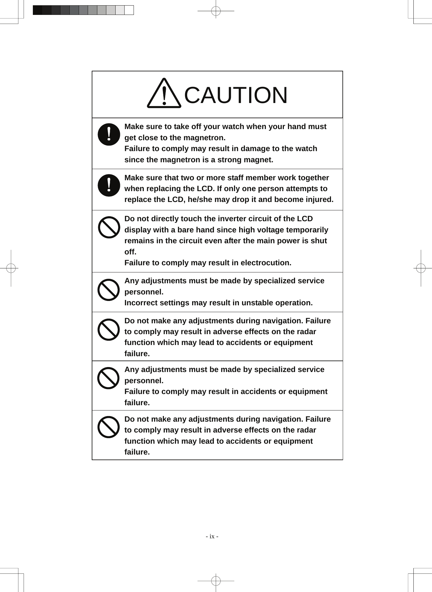
![CAUTION Use target tracking function only as a navigation aid. The final navigation decision must always be made by the operator him/herself. Making the final navigation decision based only on tracking target information may cause accidents. Tracking target information such as vector, target numerical data, and alarms may contain some errors. Also, targets that are not detected by the radar cannot be acquired or tracked. Making the final navigation decision based only on the radar display may cause accidents such as collisions or When using the [AUTO SEA] function, never set the suppression level too high canceling out all image noises from the sea surface at close range. Detection of not only echoes from waves but also targets such as other ships or dangerous objects will become inhibited. When using the [AUTO SEA] function, make sure to choose the most appropriate image noise suppression level. When using the [AUTO RAIN] function, never set the suppression level too high canceling out all image noises from the rain or snow at close range. Detection of not only echoes from the rain or snow but also targets such as other ships or dangerous objects will become inhibited. When using the [AUTO RAIN] function, make sure to choose the most appropriate image noise suppression level. A malfunction may occur if the power in the ship is instantaneously interrupted during operation of the radar. In this case, the power should be turned on again. - vii -](https://usermanual.wiki/Japan-Radio/NKE2103.Users-Manual-1/User-Guide-991971-Page-13.png)
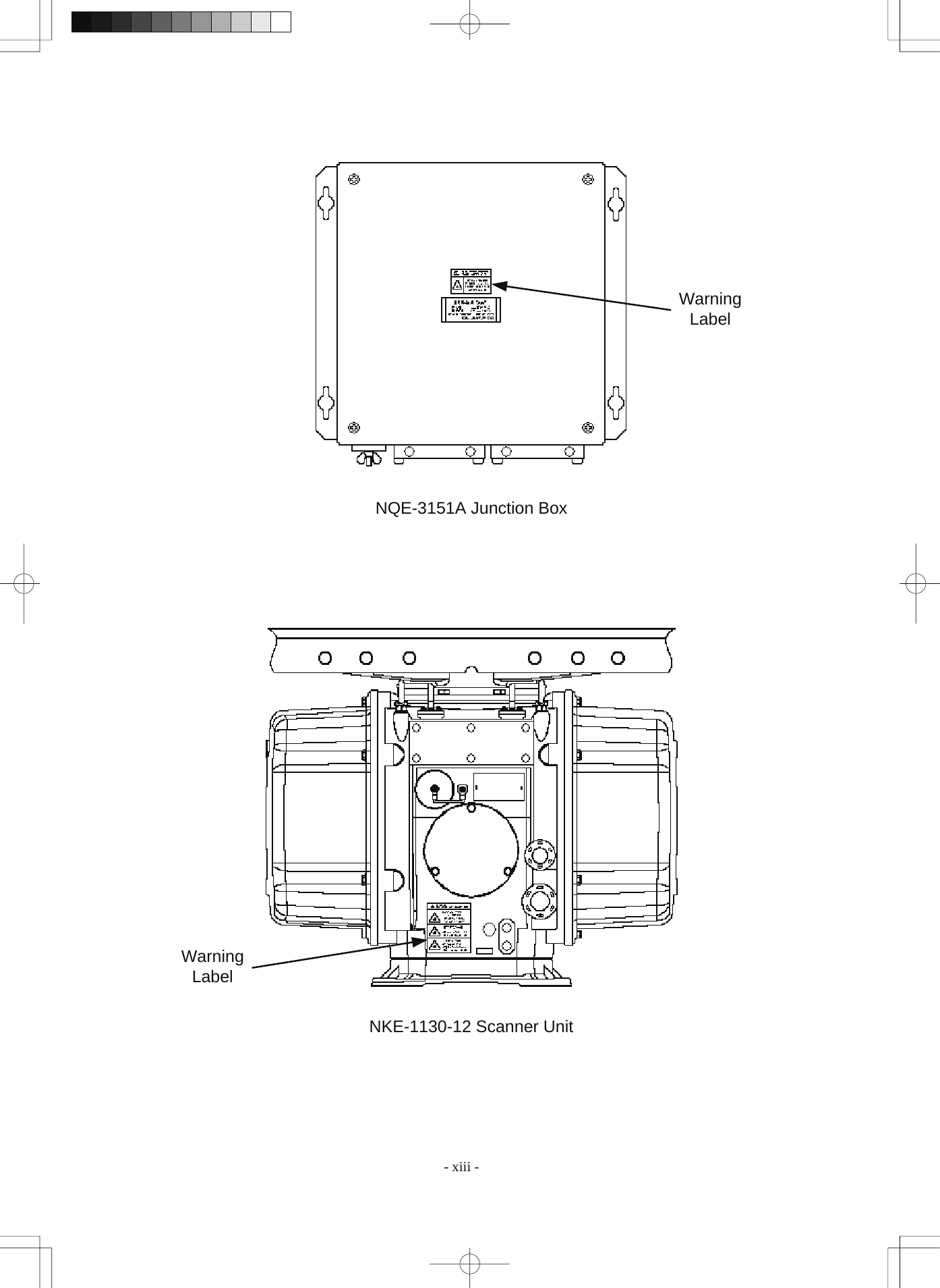
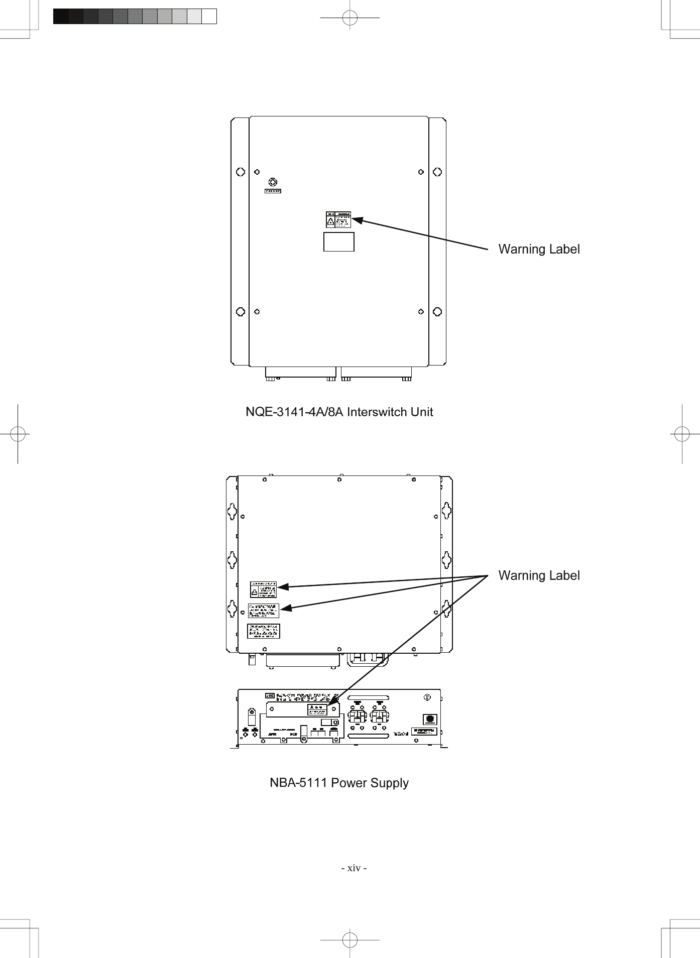
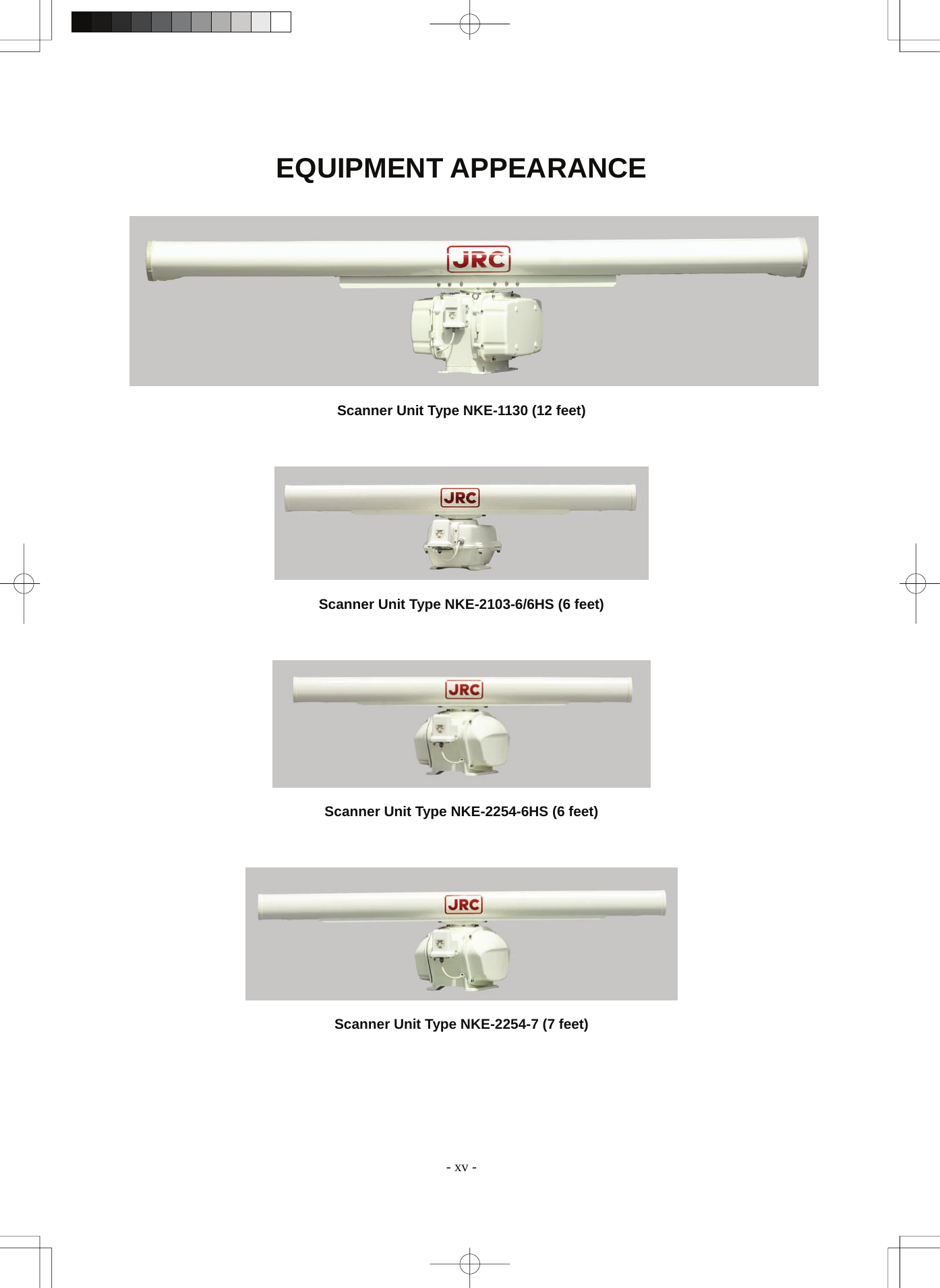
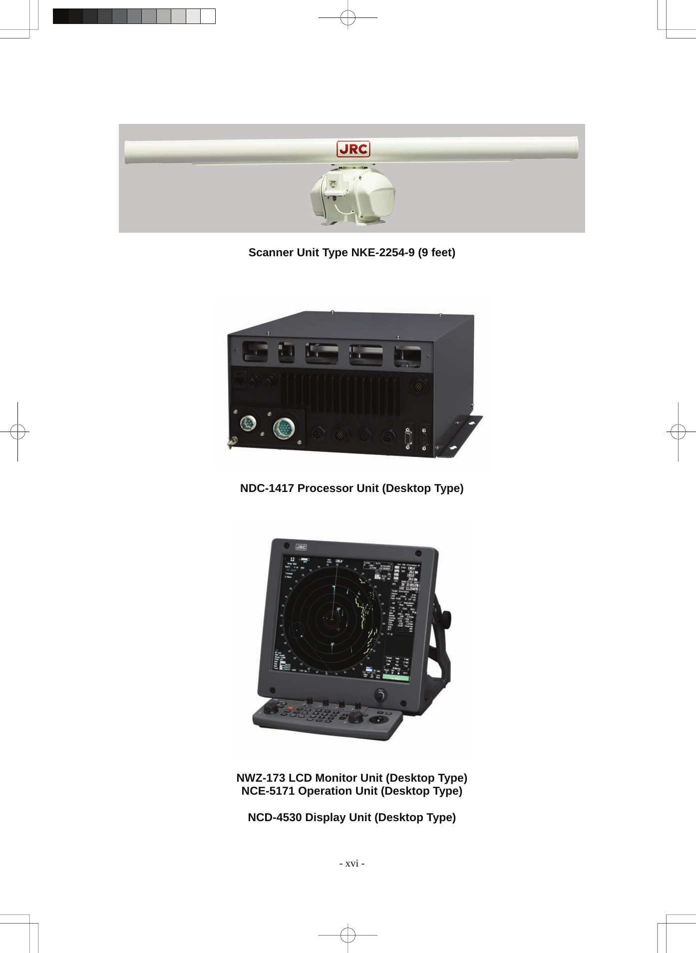
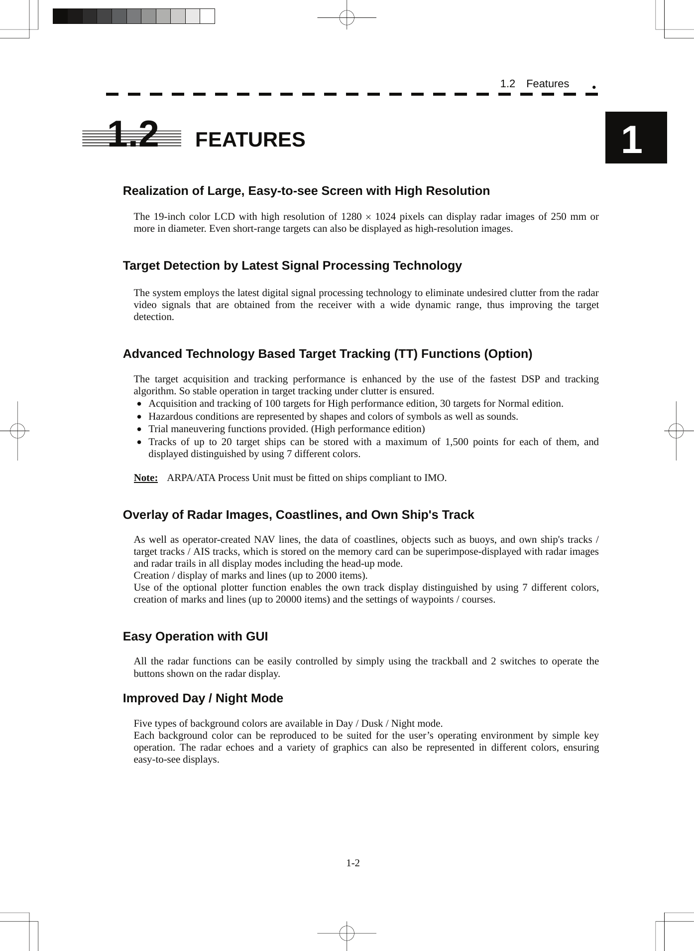
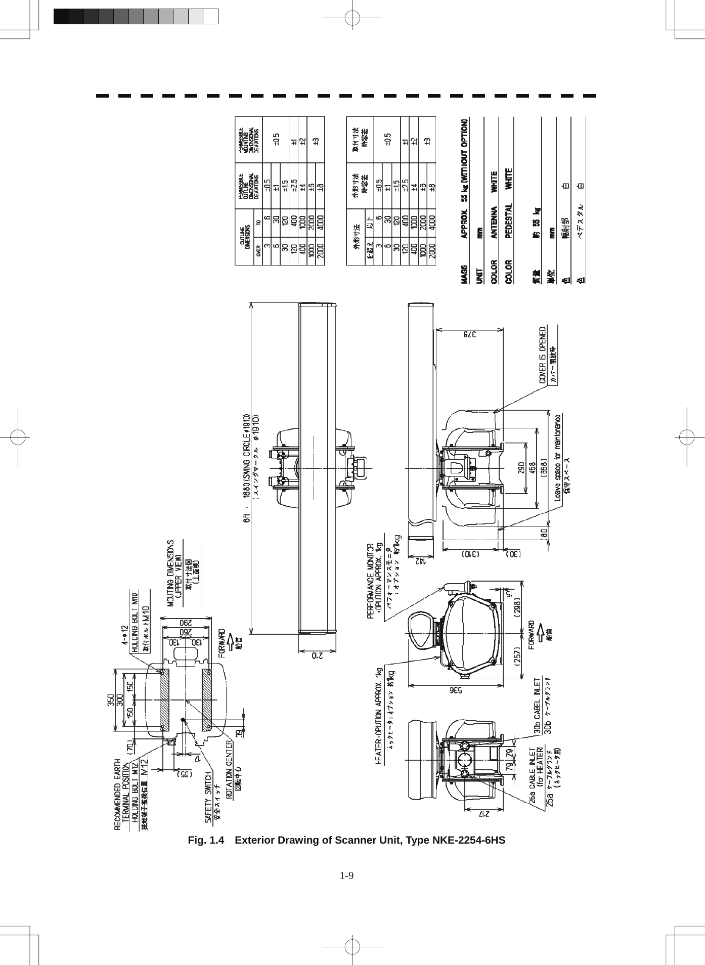
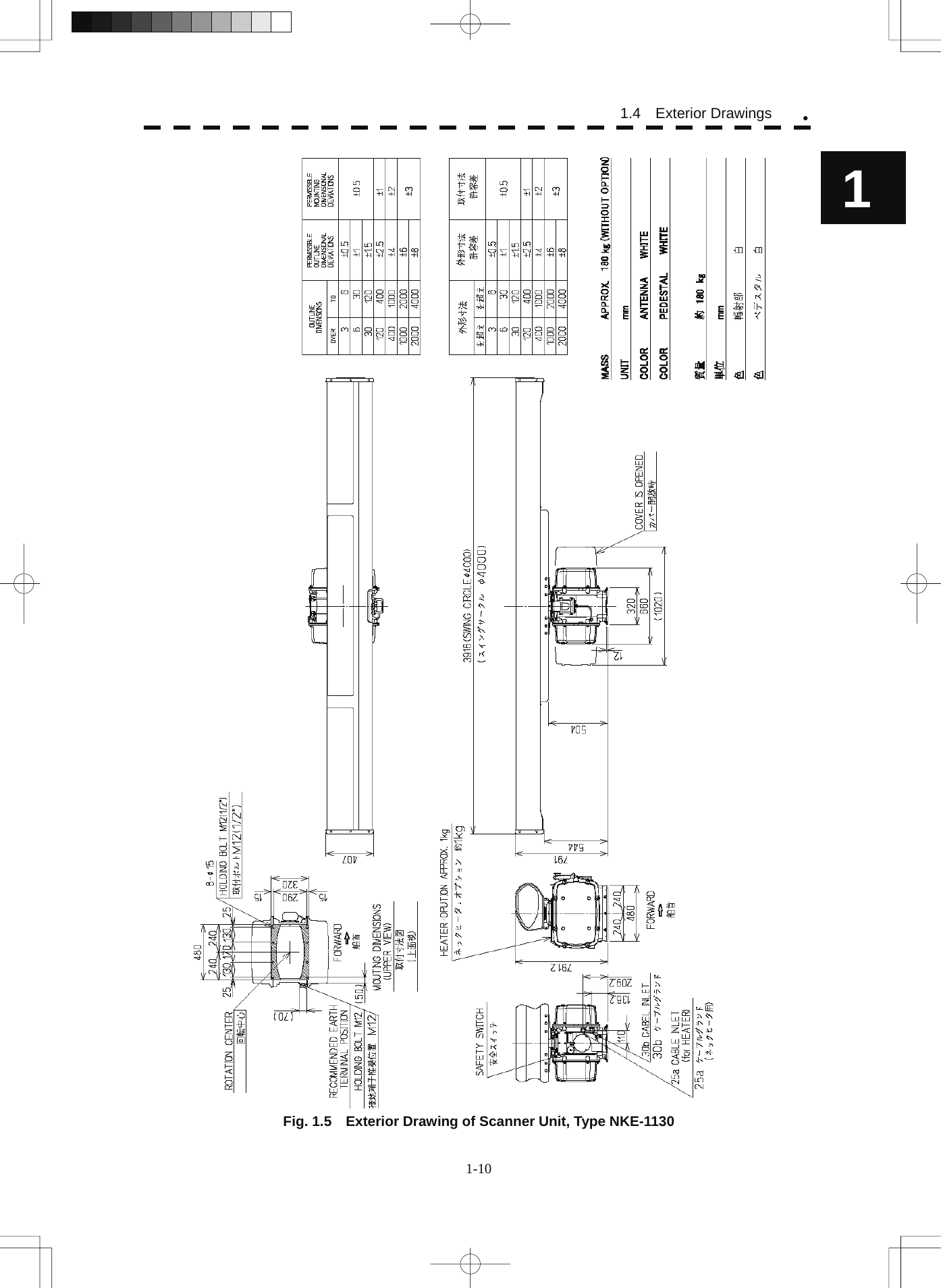
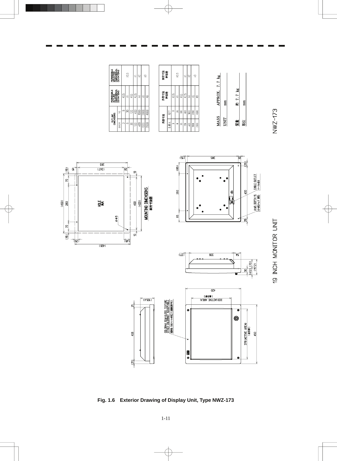
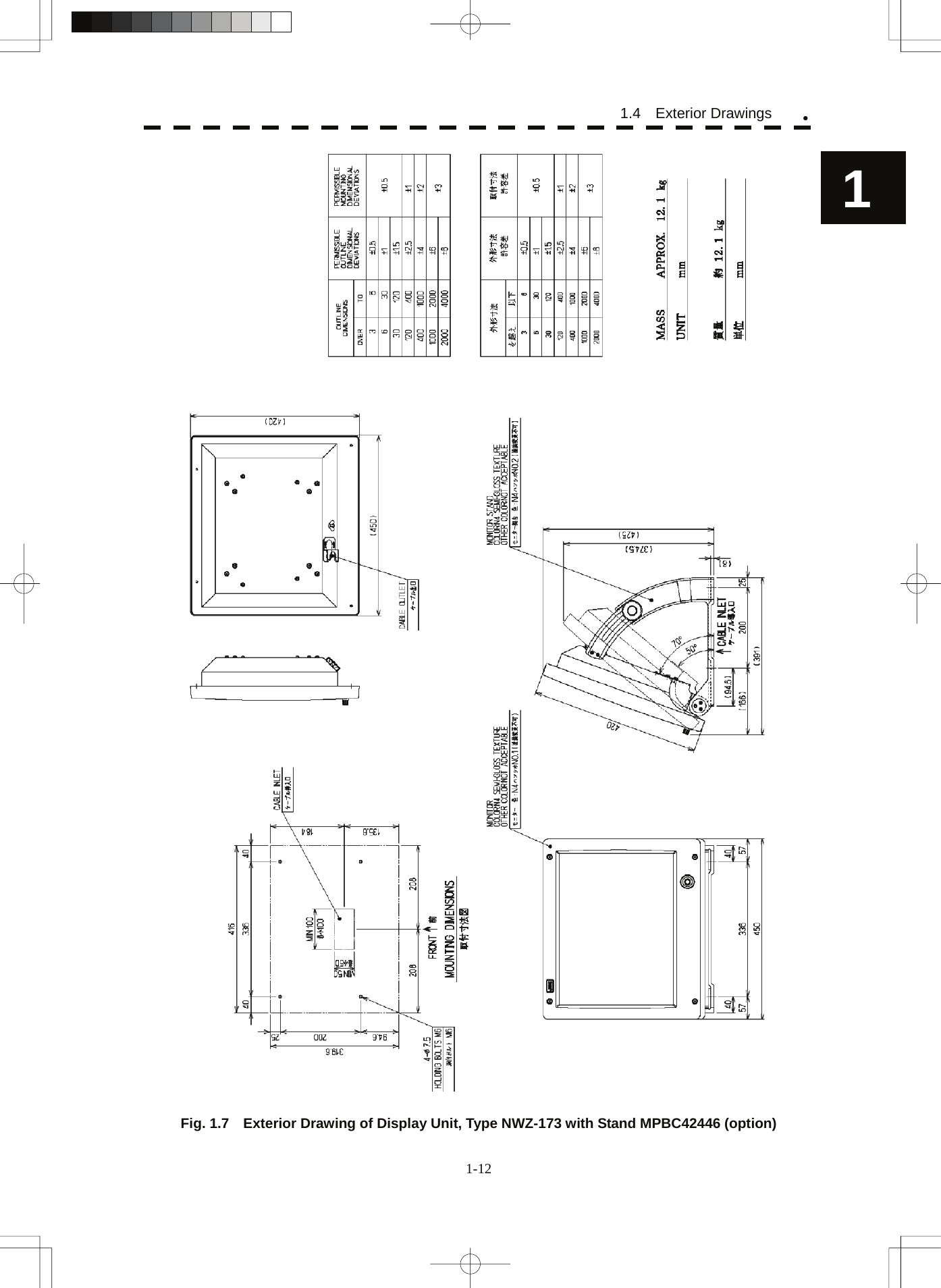
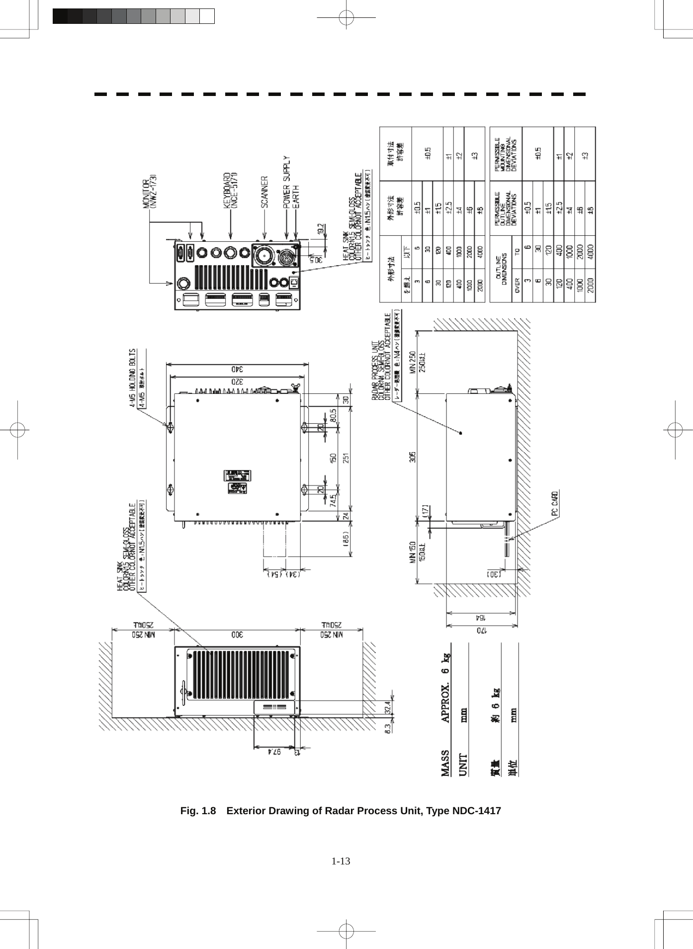
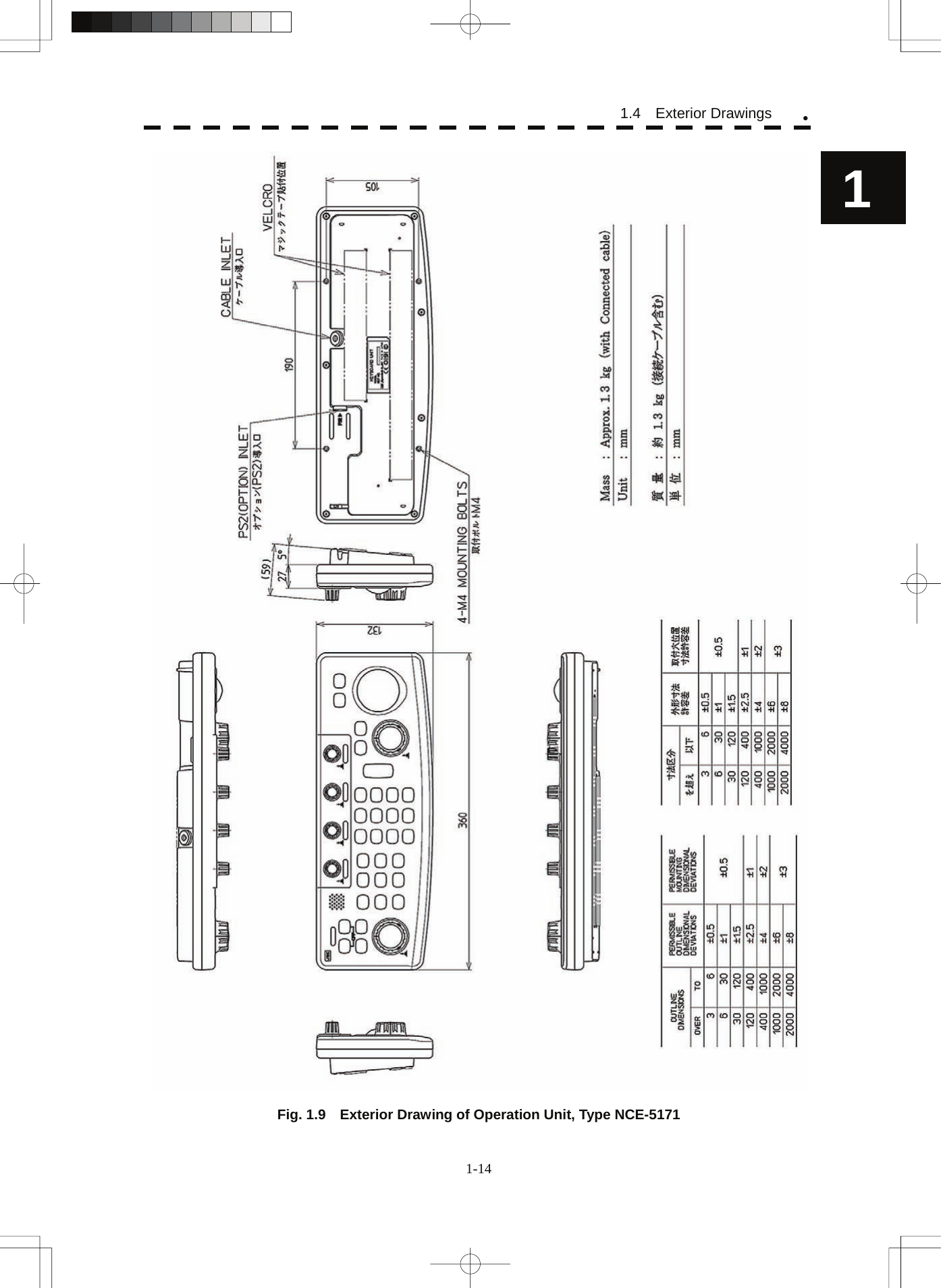
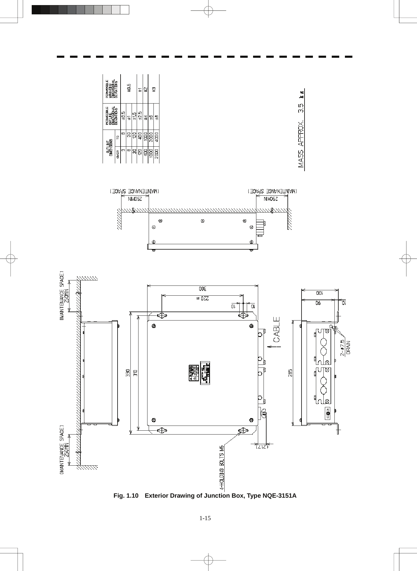
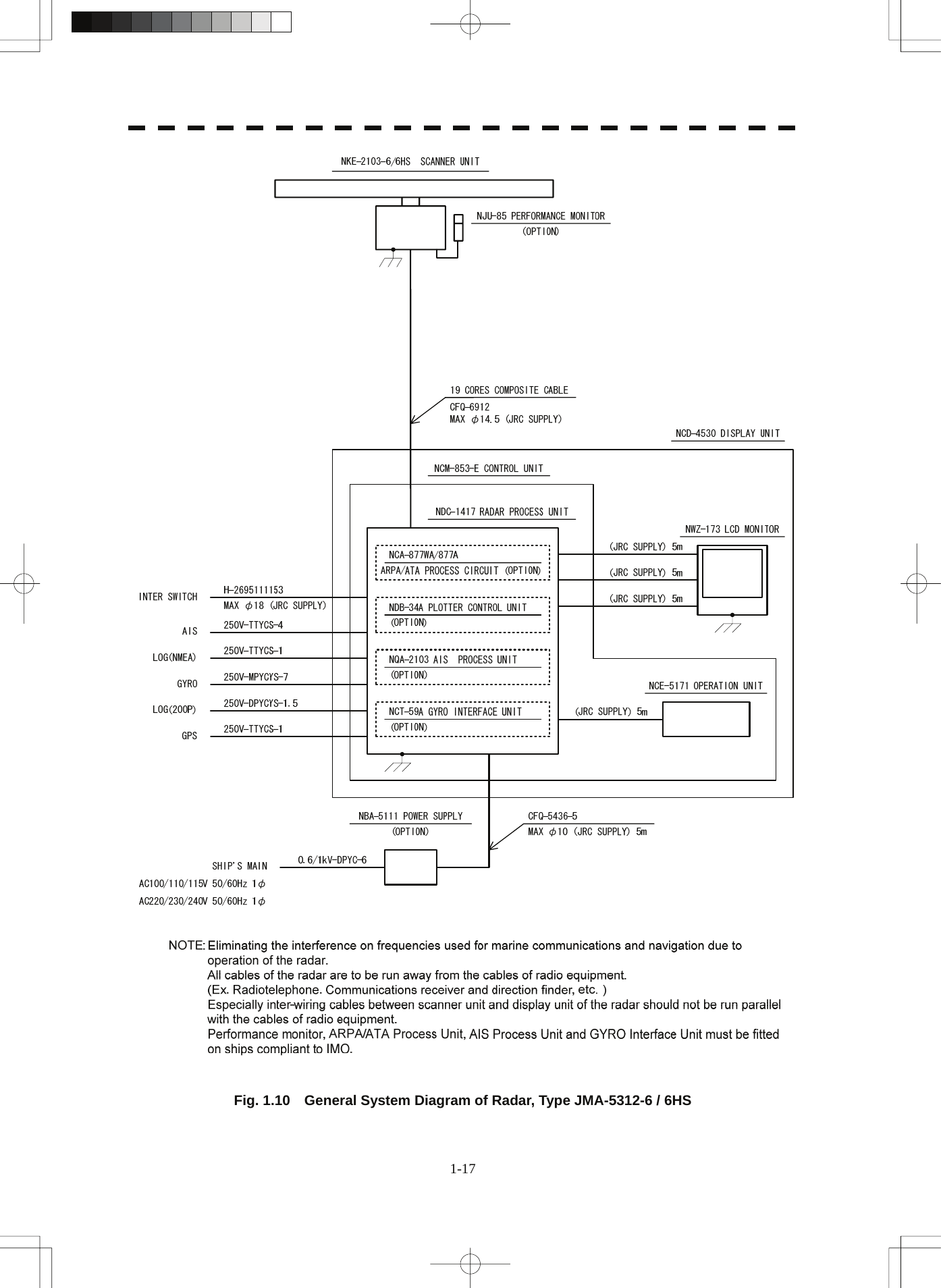
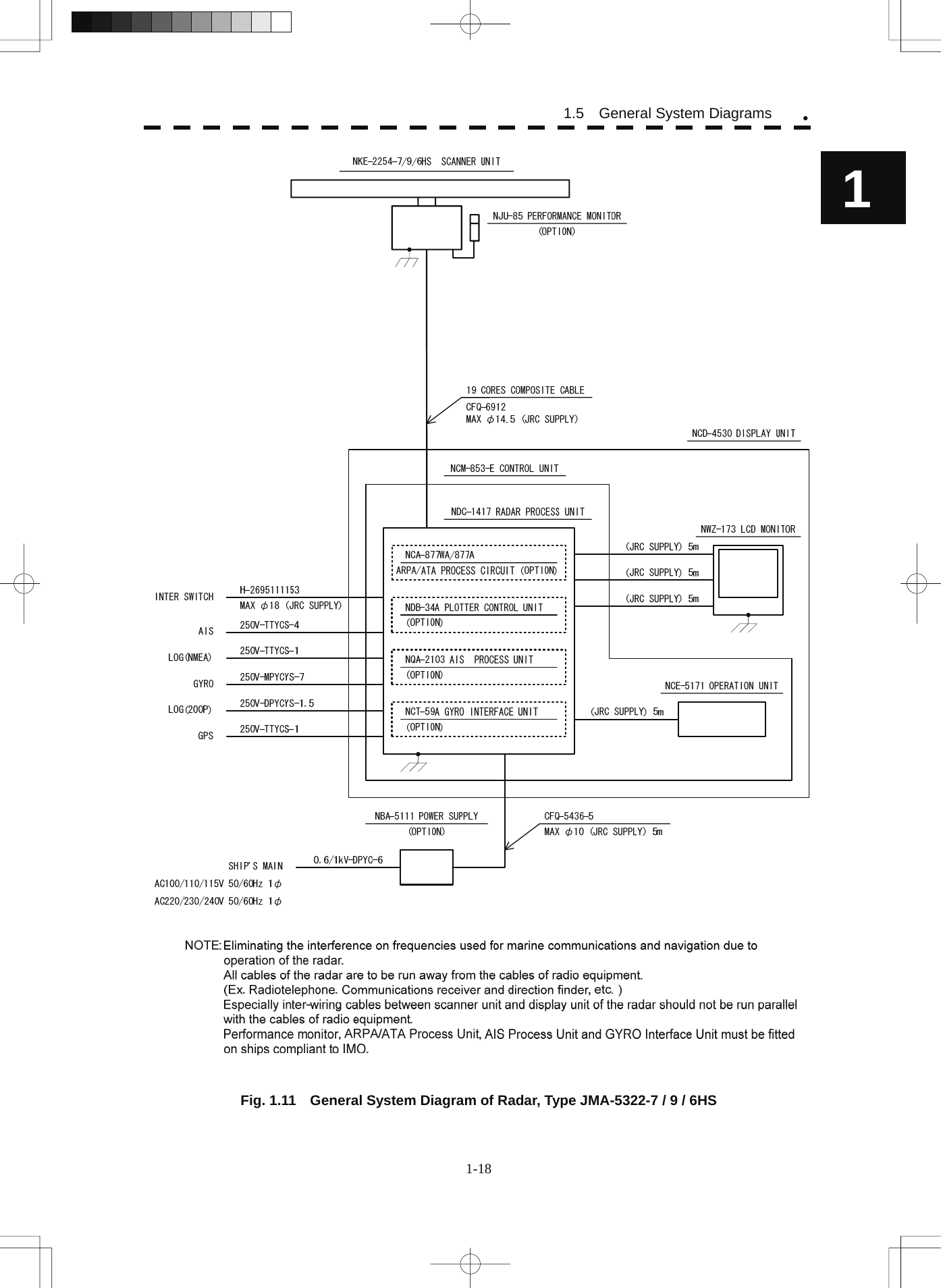
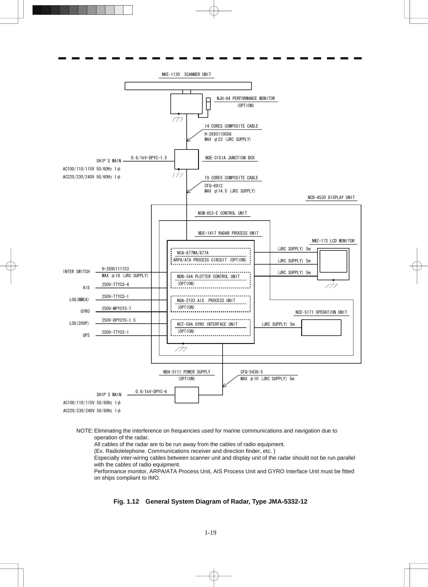
![CONTENTS PREFACE...............................................................................................................i BEFORE OPERATION.......................................................................................... ii PRECAUTIONS....................................................................................................iii The Mounting Point of the Warning Label ........................................................xi EQUIPMENT APPEARANCE..............................................................................xv GLOSSARY.......................................................................................................xvii 1. GENERAL AND EQUIPMENT COMPOSITION 1.1 FUNCTIONS..............................................................................................1-1 1.1.1 FUNCTION OF THIS SYSTEM ............................................................1-1 1.2 FEATURES................................................................................................1-2 1.3 CONFIGURATION.....................................................................................1-4 1.4 EXTERIOR DRAWINGS............................................................................1-5 1.5 GENERAL SYSTEM DIAGRAMS............................................................1-15 2. NAMES AND FUNCTIONS OF CONTROL PANEL KEYS AND FUNCTIONS OF SOFTWARE BUTTONS 2.1 NAMES OF DISPLAY................................................................................2-1 2.2 NAMES AND FUNCTIONS OF CONTROL PANEL KEYS ......................2-10 2.3 FUNCTIONS OF SOFTWARE BUTTONS...............................................2-15 3. BASIC OPERATION 3.1 OPERATION FLOW ..................................................................................3-1 3.1.1 POWER ON AND START THE SYSTEM..............................................3-2 3.1.2 OBSERVE AND ADJUST VIDEO.........................................................3-3 3.1.3 ACQUIRE AND MEASURE DATA........................................................3-3 3.1.4 DISPLAY AND MEASURE WITH REFERENCE TO CCRP..................3-3 3.1.5 END THE OPERATION AND STOP THE SYSTEM..............................3-4 3.2 OBSERVE AND ADJUST VIDEO..............................................................3-5 3.2.1 ADJUST MONITOR BRILLIANCE [BRILL]..........................................3-5 3.2.2 CHANGE OBSERVATION RANGE [RANGE + / - ] ..............................3-5 3.2.3 TUNE....................................................................................................3-6 3.2.4 ADJUST GAIN [GAIN / PL] ..................................................................3-7 3.2.5 SUPPRESS SEA CLUTTER [AUTO-SEA]...........................................3-8](https://usermanual.wiki/Japan-Radio/NKE2103.Users-Manual-1/User-Guide-991971-Page-29.png)
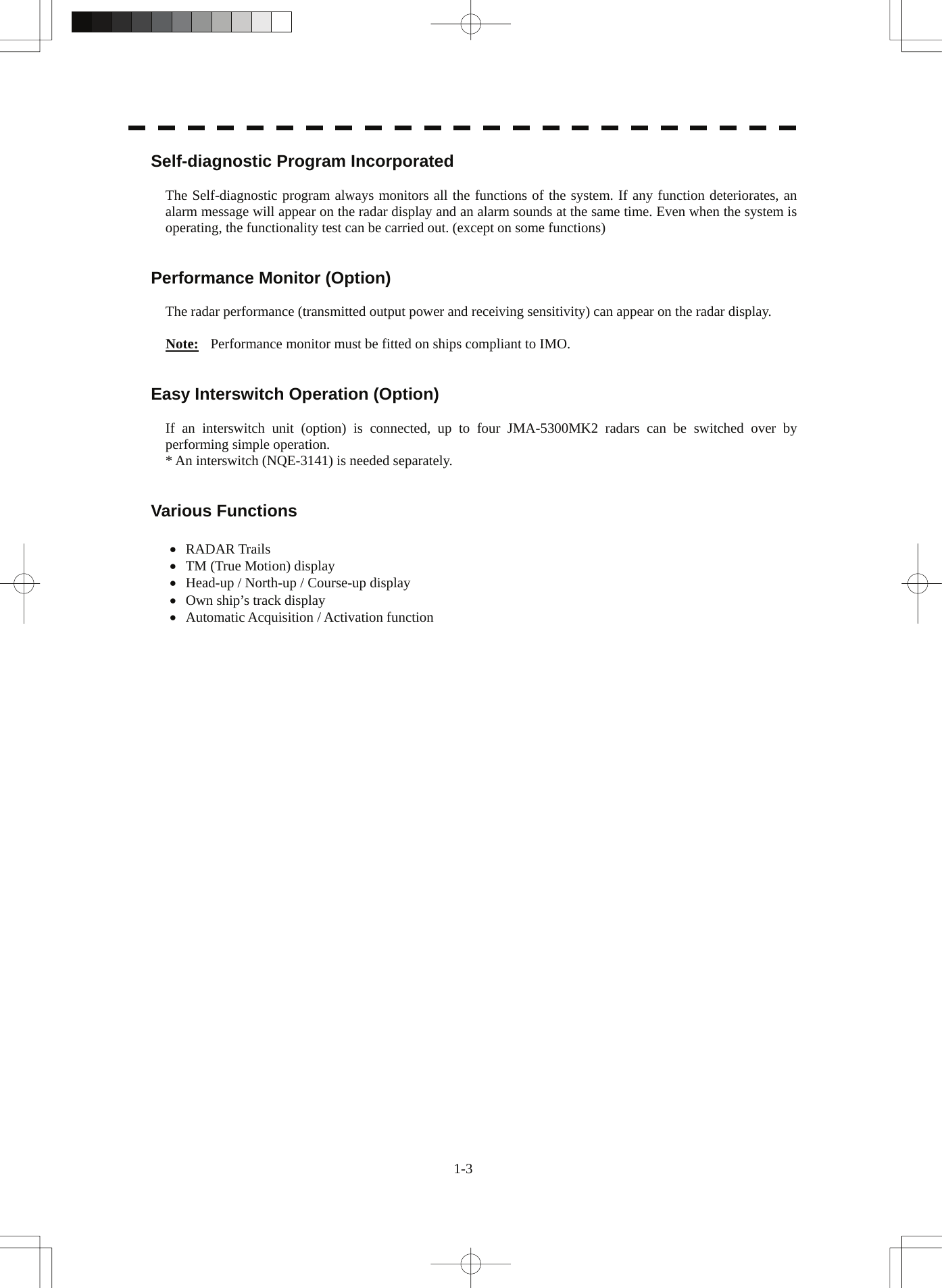
![3.2.6 SUPPRESS RAIN / SNOW CLUTTER [AUTO-RAIN].......................... 3-9 3.2.7 RESET ALARM BUZZER [ALARM ACK].......................................... 3-10 3.3 OPERATION PROCEDURES ................................................................. 3-11 3.3.1 MOVE CROSS CURSOR MARK BY TRACKBALL........................... 3-11 3.3.2 OPERATE SOFTWARE BUTTONS................................................... 3-12 3.3.3 BASIC MENU OPERATION............................................................... 3-13 3.3.4 OPERATION ON NUMERIC VALUE, LATITUDE / LONGITUDE AND CHARACTER INPUT MENU.............................................................. 3-15 3.3.5 OVERVIEW OF MENU STRUCTURE................................................ 3-19 3.3.6 OPERATE MULTI-DIAL [MULTI] ....................................................... 3-19 3.4 GENERAL RADAR OPERATION ........................................................... 3-21 3.4.1 INTERFERENCE REJECTION (IR) ................................................... 3-21 3.4.2 SWITCH TRANSMITTER PULSE LENGTH [GAIN / PL] ................... 3-22 3.4.3 TARGET ENHANCE (ENH)................................................................ 3-23 3.4.4 USE VIDEO PROCESSING (PROC).................................................. 3-24 3.4.5 SWITCH AZIMUTH DISPLAY MODE [AZI MODE] ............................ 3-25 3.4.6 SWITCH TRUE / RELATIVE MOTION DISPLAY MODE [TM / RM].... 3-26 3.4.7 MOVE OWN SHIP’S DISPLAY POSITION [OFF CENT].................... 3-27 3.4.8 DISPLAY RADAR TRAILS [TRAILS]................................................. 3-28 3.4.9 ERASE PART OF RADAR TRAILS (TRAILS ERASE) ...................... 3-30 3.4.10 OPERATE RADAR TRAILS FILE (FILE OPERATIONS) ................... 3-31 3.4.11 ZOOM (X2)......................................................................................... 3-33 3.4.12 HIDE / DISPLAY RANGE RINGS (RR / HL) ....................................... 3-33 3.4.13 HIDE GRAPHICS INFORMATION ON RADAR DISPLAY (DATA OFF) ...................................................................................... 3-34 3.4.14 SWITCH DAY / NIGHT MODE [DAY / NIGHT].................................... 3-34 3.4.15 ADJUST OPERATION PANEL BRILLIANCE [PANEL] ..................... 3-34 3.4.16 SET TRUE BEARING (GYRO SETTING) .......................................... 3-35 3.4.17 SET OWN SHIP SPEED..................................................................... 3-35 3.4.18 MAGNET COMPASS CORRECTION (MAG COMPASS SETTING).. 3-36 3.4.19 SET DRIFT CORRECTION (SET / DRIFT SETTING)......................... 3-37 3.4.20 GPS RECEIVER SETTING (GPS PROCESS SETTING)................... 3-38 3.4.21 DGPS RECEIVER SETTING (DGPS SETTING)................................ 3-42 3.4.22 SBAS RECEIVER SETTING (SBAS SETTING)................................. 3-43 3.4.23 DISPLAYING GPS RECEPTION STATUS (GPS STATUS)................ 3-46 3.4.24 SET RADAR ALARM (RADAR ALARM) ........................................... 3-47 3.5 USE OWN SHIP'S TRACK DATA............................................................ 3-49 3.5.1 DISPLAY OWN SHIP’S TRACK (DISPLAY OWN TRACK)................ 3-49 3.5.2 SAVE OWN SHIP'S TRACK DATA (OWN TRACK MEMORY)........... 3-50 3.5.3 CANCEL SAVING OF OWN SHIP’S TRACK DATA (OWN TRACK MEMORY).......................................................................................... 3-50 3.5.4 CLEAR OWN SHIP’S TRACK DATA (CLEAR OWN TRACK) ........... 3-50 3.5.5 OPERATE OWN SHIP'S TRACK FILES (FILE OPERATIONS)......... 3-51 3.6 DISPLAY USER MAP.............................................................................. 3-54 3.6.1 CREATE USER MAP (MARK / LINE)................................................. 3-54 3.6.2 SET USER MAP DISPLAY (MARK DISPLAY SETTING)................... 3-57 3.6.3 EDIT USER MAP (EDIT USER MAP)................................................. 3-60 3.6.4 EDIT MARK / LINE LIST (MARK / LINE LIST) ................................... 3-66 3.6.5 CORRECT POSITION ON USER MAP (SHIFT USER MAP) ............. 3-72 3.6.6 OPERATE USER MAP FILE (FILE OPERATIONS) ........................... 3-73](https://usermanual.wiki/Japan-Radio/NKE2103.Users-Manual-1/User-Guide-991971-Page-30.png)
![3.6.7 SET AND DISPLAY GEODETIC SYSTEM (GEODETIC)....................3-77 3.7 USE ROUTE FUNCTION.........................................................................3-78 3.7.1 DISPLAY DESTINATION MARK (NMEA WAYPOINT DISPLAY) .......3-78 3.8 APPLIED OPERATIONS.........................................................................3-79 3.8.1 SET RADAR SIGNAL PROCESSING (PROCESS SETTING) ...........3-79 3.8.2 SET RADAR TRAILS (RADAR TRAILS SETTING) ...........................3-81 3.8.3 SET SCANNER UNIT (TXRX SETTING)............................................3-83 3.8.4 SET CURSOR (CURSOR SETTING) .................................................3-84 3.8.5 SET RADAR DISPLAY (DISPLAY SETTING) ....................................3-85 3.8.6 ADJUST SOUND VOLUME (BUZZER VOLUME)..............................3-87 3.8.7 SET USER KEYS [USER KEY 1 / 2]...................................................3-88 3.8.8 SET NAVIGATION DATA DISPLAY (MULTI WINDOW SETTING) .....3-90 3.9 USE FUNCTION KEY [FUNC].................................................................3-94 3.9.1 OPERATION PROCEDURES [FUNC] ...............................................3-94 3.9.2 FUNCTION SETTING MENU ITEMS (USER FUNCTION SETTING) .3-95 3.9.3 OVERVIEW OF FUNCTION OPERATIONS (USER FUNCTION SETTING) ..........................................................3-96 3.9.4 OVERVIEW OF SAVED FUNCTION SETTING DATA........................3-99 3.10 USE USER SETTING ............................................................................3-100 3.10.1 SAVE OPERATING STATE (SAVE USER SETTING).......................3-100 3.10.2 LOAD OPERATING STATE (LOAD USER SETTING) .....................3-101 3.10.3 DELETE OPERATING STATE (DELETE USER SETTING) .............3-101 3.11 USING CARD ........................................................................................3-102 3.11.1 OPERATE FILE ON THE CARD (FILE MANAGER).........................3-102 3.12 DISPLAY SIMPLE CHART ....................................................................3-108 3.12.1 DISPLAY JRC COASTLINE ROM CARD [MAP]..............................3-108 3.12.2 DISPLAY ERC CARD [MAP]............................................................3-108 3.12.3 DISPLAY JRC CHART ON CF CARD (SEL JRC ROM CARD FILE)3-109 3.12.4 FILL CHARTS (FILL LAND AREA) .................................................. 3-110 3.12.5 SET JRC / ERC CHART DISPLAY (JRC / ERC SETTING)............... 3-111 3.12.6 DISPLAY C-MAP CARD [MAP]........................................................ 3-115 3.12.7 CORRECTING CHART POSITION (MAP DISPLAY SETTING) ....... 3-118 3.12.8 CHART PLOTTING BEARING MODE (MAP DRAW AZI MODE).....3-120 4. MEASUREMENT OF RANGE AND BEARING 4.1 USE OF NAVIGATION TOOLS..................................................................4-1 4.1.1 USING CURSOR (CURSOR)...............................................................4-2 4.1.2 USING RANGE RINGS [RR / HL]........................................................4-2 4.1.3 USING ELECTRONIC BEARING LINE (EBL1/EBL2).........................4-3 4.1.4 USING VARIABLE RANGE MARKER (VRM1 / VRM2) ......................4-6 4.1.5 USING PARALLEL INDEX LINES (PI MENU).....................................4-7 4.1.6 OPERATING EBL MANEUVER FUNCTION (EBL MANEUVER SETTING) ..........................................................4-12 4.1.7 USING MOB [MOB] ...........................................................................4-14 4.1.8 OPERATING EBL, VRM, AND PI WITH CURSOR............................4-14 4.2 MEASUREMENT OF RANGE AND BEARING........................................4-17 4.2.1 MEASUREMENT WITH CURSOR POSITION (CURSOR)................4-17](https://usermanual.wiki/Japan-Radio/NKE2103.Users-Manual-1/User-Guide-991971-Page-31.png)
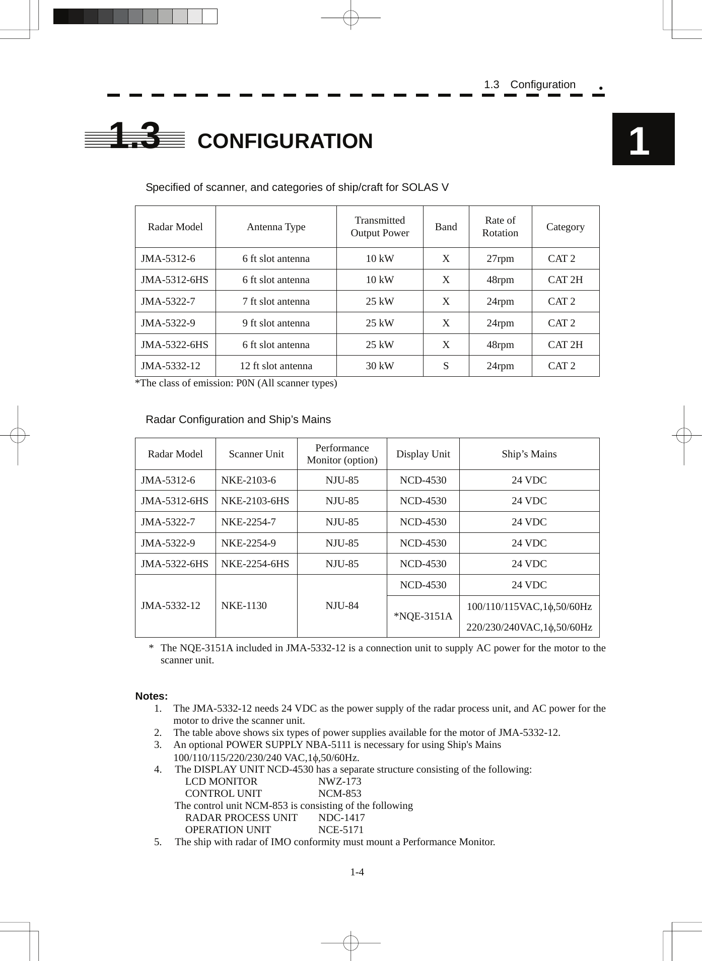
![4.2.2 MEASUREMENT WITH ELECTRONIC BEARING LINE AND VARIABLE RANGE MARKER [EBL] [VRM]................................... 4-18 4.2.3 MEASUREMENT WITH TWO ARBITRARY POINTS........................ 4-19 5. OPERATION OF TARGET TRACKING AND AIS 5.1 PREPARATION......................................................................................... 5-2 5.1.1 COLLISION AVOIDANCE.................................................................... 5-3 5.1.2 DEFINITIONS OF SYMBOLS.............................................................. 5-6 5.1.3 RADAR DISPLAY................................................................................ 5-9 5.1.4 CURSOR MODES (CURSOR)........................................................... 5-11 5.1.5 SETTING COLLISION DECISION CRITERIA................................... 5-13 5.1.6 SETTING CPA RING.......................................................................... 5-13 5.1.7 SETTING VECTORS (VECTOR TIME).............................................. 5-14 5.1.8 SETTING THE GPS ANTENNA LOCATION ..................................... 5-15 5.2 TARGET TRACKING OPERATION ........................................................ 5-16 5.2.1 ACQUIRING TARGET [ACQ]............................................................ 5-16 5.2.2 CANCELING UNWANTED TRACKED TARGETS [TGT CNCL]....... 5-19 5.2.3 TRACKED TARGET DATA DISPLAY [TGT DATA]........................... 5-20 5.2.4 DISPLAYING TARGET ID NO. (TARGET NUMBER DISPLAY)........ 5-21 5.2.5 ADDING TRACKED TARGET ID NAME (NAME) ............................. 5-22 5.2.6 REFERENCE TARGET (REFERENCE) ............................................ 5-23 5.2.7 OPERATION TEST (TT TEST MENU)............................................... 5-25 5.3 AIS OPERATION..................................................................................... 5-30 5.3.1 RESTRICTIONS................................................................................. 5-30 5.3.2 SETTING AIS DISPLAY FUNCTION (AIS FUNCTION)..................... 5-30 5.3.3 ACTIVATE AIS TARGETS (ACTIVATE AIS)...................................... 5-31 5.3.4 DEACTIVATE AIS TARGETS (DEACTIVATE AIS)............................ 5-31 5.3.5 DISPLAYING AIS INFORMATION [TGT DATA]................................ 5-32 5.3.6 DISPLAYING TARGET ID NO. (TARGET NUMBER DISPLAY)........ 5-35 5.3.7 SETTING AIS FILTER (AIS FILTER SETTING)................................. 5-35 5.3.8 CONDITIONS FOR DECIDING AIS TARGET TO BE LOST............. 5-38 5.3.9 SETTING CONDITIONS FOR AIS ALARM (AIS ALARM SETTING) 5-39 5.4 DECISION OF TARGETS AS IDENTICAL (ASSOCIATION) .................. 5-40 5.5 ALARM DISPLAY ................................................................................... 5-42 5.6 TRACK FUNCTION ................................................................................ 5-46 5.6.1 PAST POSITION (PAST POSN)........................................................ 5-46 5.6.2 TARGET SHIP'S TRACKS (TARGET TRACK)................................. 5-47 5.7 TRIAL MANEUVERING (TRIAL MANEUVER) ....................................... 5-56 6. TRUE AND FALSE ECHOES ON DISPLAY 6.1 RADAR WAVE WITH THE HORIZON ....................................................... 6-1 6.2 STRENGTH OF REFLECTION FROM THE TARGET............................... 6-3 6.3 SEA CLUTTER AND RAIN AND SNOW CLUTTER.................................. 6-5 6.4 FALSE ECHOES....................................................................................... 6-9 6.5 DISPLAY OF RADAR TRANSPONDER (SART) .................................... 6-12](https://usermanual.wiki/Japan-Radio/NKE2103.Users-Manual-1/User-Guide-991971-Page-32.png)

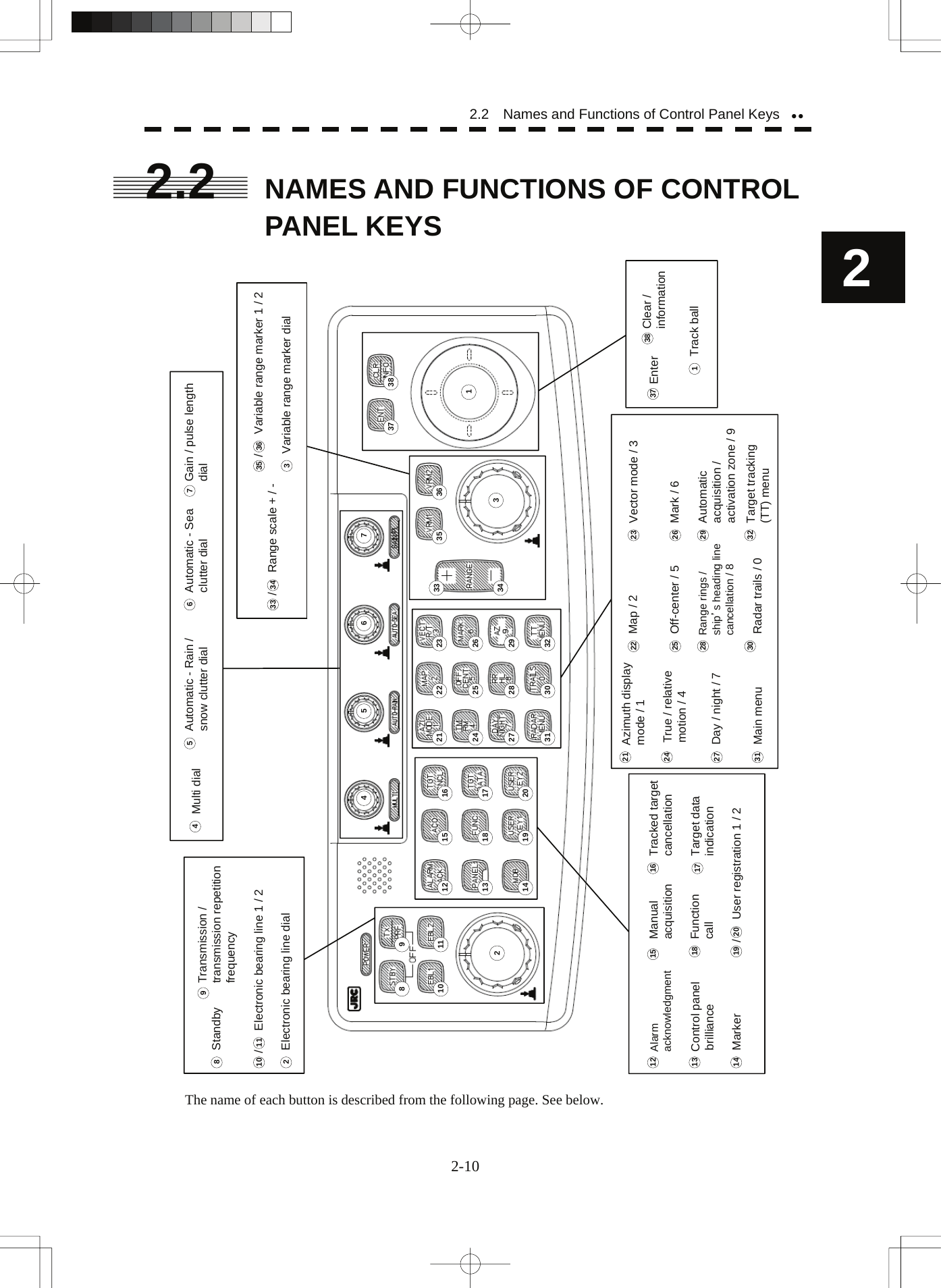
![1 Track ball Use the track ball to move the cursor mark to any position. For example, use it for setting in each mode and specifying a floating EBL center position and off-center position. 2 [EBL] (Electronic Bearing Line) dial Turn the dial to rotate the bearing of the EBL. By pressing the dial, the selected EBL can be switched. (Center fixing) ⇒ C (Floating) ⇒ D (latitude / longitude fixing) ⇒ * D is enabled only when the navigator is connected. 3 [VRM] (Variable Range Marker) dial Turn the dial to change the VRM range. Press the dial to set the display of parallel index line (PI) to On / Off and open the PI Menu. 4 [MULTI] dial Press the dial to switch the function that is registered in the multi-dial. Vector ⇒ Trails ⇒ TGT No. ⇒ Course ⇒ Track ⇒ Mark ⇒ Tune ⇒ Vector The function that is switched is displayed in multi-dial mode (lower left of the display on page 2-3) If the dial is pressed for 2 seconds, the Multi Dial Setting menu is opened. If the dial is pressed again for 2 seconds, the setting menu is closed. 5 [AUTO-RAIN] (Automatic - Rain / Snow clutter suppression) dial Turn the dial to suppress images by rain / snow clutter. Turn the dial clockwise to increase the effect of suppression. Press the dial to switch the mode to manual / automatic. 6 [AUTO-SEA] (Automatic - Sea clutter suppression) dial Turn the dial to suppress images by sea clutter. Turn the dial clockwise to increase the effect of suppression. Press the dial to switch the mode to manual / automatic. 7 [GAIN / PL] (Gain / Pulse Length) dial Turn the dial to adjust the reception gain of the radar. Turn the dial clockwise to increase the gain. Press the dial to switch the transmitting pulse length. 8 [STBY] (Standby) key Use this key to turn on the power of the equipment. Use this key also to switch the equipment from a transmitting state to a standby state. The power can be turned off by pressing the [STBY] key and [TX / PRF] key concurrently while the power is On. 9 [TX / PRF] (Transmission / transmission repetition frequency) key At expiration of the pre-heat time after the power is turned on, Preheat of the transmission / standby indication (Upper left of the display on page 2-2) changes to Standby . If this key is pressed subsequently, transmission starts. If this key is pressed during transmission, fine adjustments of the transmission repetition frequency are enabled. By using the fine adjustments of the transmission repetition frequency and the interference removal function, the interference suppression effect can be improved. 2-11](https://usermanual.wiki/Japan-Radio/NKE2103.Users-Manual-1/User-Guide-991971-Page-70.png)
![2 2.2 Names and Functions of Control Panel Keysyy 10 / 11 [EBL1] / [EBL2] (Electronic Bearing Line 1 / 2) key Use these keys to switch EBL1 / EBL2 to On / Off. If the key is pressed for 2 seconds, the EBL / Cursor Setting menu is opened. 12 [ALARM ACK] (Alarm acknowledgment) key Use this key to acknowledge the alarm such as a failure alarm and a collision alarm. To stop the alarm, press this key while the alarm sound is emitted. If multiple alarms occur, press this key same time as the alarms. 13 [PANEL] (Control panel brilliance) key Use this key to adjust the brilliance of various keys and dials on the control panel. 14 [MOB] (Marker) key A marker is set on the own ship's position latitude / longitude at that time. Use this key to store the own ship's position at the time in such a case that someone falls overboard from the ship. The marker can be cleared by pressing the key for 2 seconds. 15 [ACQ] (Manual acquisition) key Use this key to acquire a target of the cursor position manually. 16 [TGT CNCL] (Tracked target cancellation) key Use this key to cancel the tracked target symbol / vector at the cursor position and stop tracking. When this key is pressed for 2 seconds, all the tracked target symbols / vectors are cancelled and tracking is stopped. 17 [TGT DATA] (Target data indication) key Use this key to check the digital information of the AIS target or the tracked target. 18 [FUNC] (Function call) key Use this key to switch the original signal processing settings. FUNC Off ⇒ Coast ⇒ Deep Sea ⇒ Fishnet ⇒ Storm ⇒ FUNC Off If the key is pressed for 2 seconds, the User Function Setting menu is displayed. 19 / 20 [USER KEY 1 / 2] (User registration 1 / 2) key Use this key to perform pre-registered operations. If this key is pressed for 2 seconds while no operation is registered, the User Key Setting menu is opened. 21 [AZI MODE / 1] (Azimuth display mode / 1) key Switch the azimuth display. H Up (Head Up) ⇒ N Up (North Up) ⇒ C Up (Course Up) ⇒ N Up During the menu operation, the key functions as a numeric key [1]. If this key is pressed for 2 seconds, GYRO setting menu is opened. 22 [MAP / 2] key Use this key to switch the map display to On / Off such as marine chart, coastline, and depth contour. During the menu operation, the key functions as a numeric key [2]. If this key is pressed for 2 seconds, the Map Setting menu is opened. 23 [VECT R / T / 3] (Vector mode / 3) Use this key to switch vector indication T (true vector) / R (relative vector). During the menu operation, the key functions as a numeric key [3]. 2-12](https://usermanual.wiki/Japan-Radio/NKE2103.Users-Manual-1/User-Guide-991971-Page-71.png)
![24 [TM / RM / 4] (True Motion / Relative Motion / 4) key Use this key to switch the motion mode between TM (true motion) and RM (relative motion). If the key is pressed for 2 seconds in TM , the own ship's position is reset. During the menu operation, the key functions as a numeric key [4]. 25 [OFF CENT / 5] (Off-center / 5) key By pressing this key, moving the cursor, and pressing the [ENT] key, the ship's position can be moved to the cursor position. The moving range is about 66% of the radius. If the key is pressed for 2 seconds, the off-center is set to Off and the ship's position is returned to the center of the screen. During the menu operation, the key functions as a numeric key [5]. 26 [MARK / 6] (Mark / 6) key Use this key to display a mark in any screen position. This key can also be used for clearing the mark that is currently displayed. If the key is pressed for 2 seconds, the Mark Setting menu is opened. During the menu operation, the key functions as a numeric key [6]. 27 [DAY / NIGHT / 7] (Day / night mode / 7) key Use this key to switch the color and brightness of the screen that have been set in advance. If the key is pressed for 2 seconds, the Display Color Setting menu is opened. During the menu operation, the key functions as a numeric key [7]. 28 [RR / HL / 8] (Range Rings / ship's heading line off / 8) key Use this key to set the range rings marker to On / Off. If the key is pressed for 2 seconds, the ship's heading line is cleared while the key is pressed. During the menu operation, the key functions as a numeric key [8]. 29 [AZ / 9] (Automatic Acquisition / Activation Zone / 9) key Use this key to set automatic acquisition / activation zone. If the key is pressed for 2 seconds, the AZ Menu (automatic acquisition / activation zone menu) is opened. During the menu operation, the key functions as a numeric key [9]. 30 [TRAILS / 0] (Radar trails / 0) key Use this key to switch the length of the radar trail period. If the key is pressed for 2 seconds, the RADAR Trails setting menu is opened. If this key is pressed for 5 seconds, the radar trail is cleared. During the menu operation, the key functions as a numeric key [0]. 31 [RADAR Menu] (Main menu) key Use this key to open the Main Menu. 32 [TT Menu] key Use this key to open the TT Menu (target tracking menu). 33 / 34 [RANGE + / - ] key Press the [+] key to increase the observation range and the [-] key to reduce the observation range. 35 / 36 [VRM 1 / 2 ] (Variable Range Marker 1 / 2) key Use this key to set the display of VRM1 / VRM2 to On / Off and acquire the operation right. 2-13](https://usermanual.wiki/Japan-Radio/NKE2103.Users-Manual-1/User-Guide-991971-Page-72.png)
![2 2.2 Names and Functions of Control Panel Keysyy 37 [ENT] (Enter) key Use this key to confirm menu selection and input of numeric values. This key is equivalent to the clicking of the left button of the track ball. 38 [CLR / INFO] (Clear / information) key Use this key to cancel menu selection or numeric value input. This key is equivalent to the clicking of the right button of the track ball. 2-14](https://usermanual.wiki/Japan-Radio/NKE2103.Users-Manual-1/User-Guide-991971-Page-73.png)
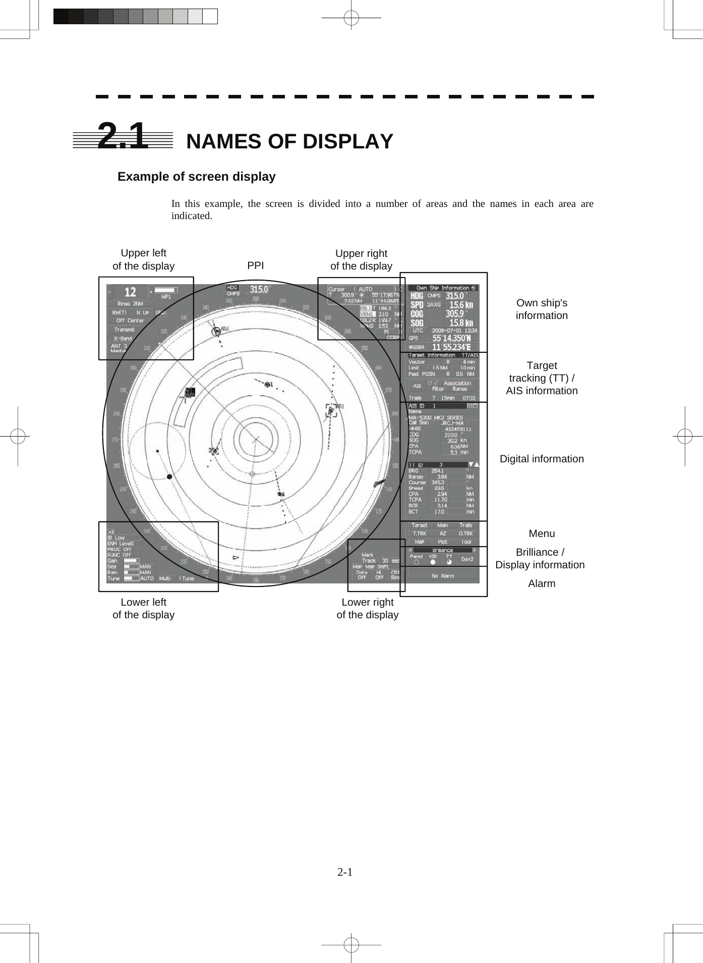
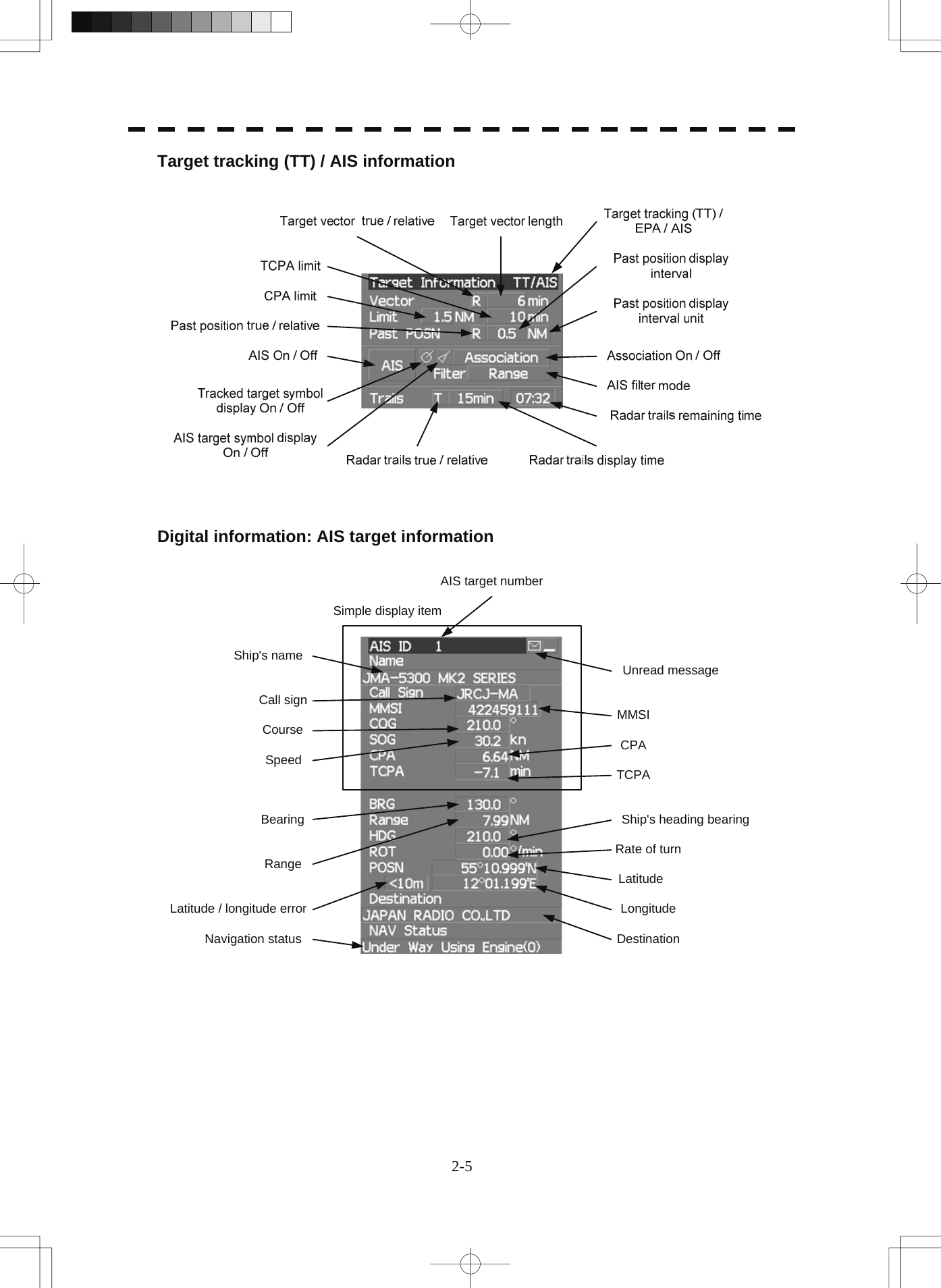
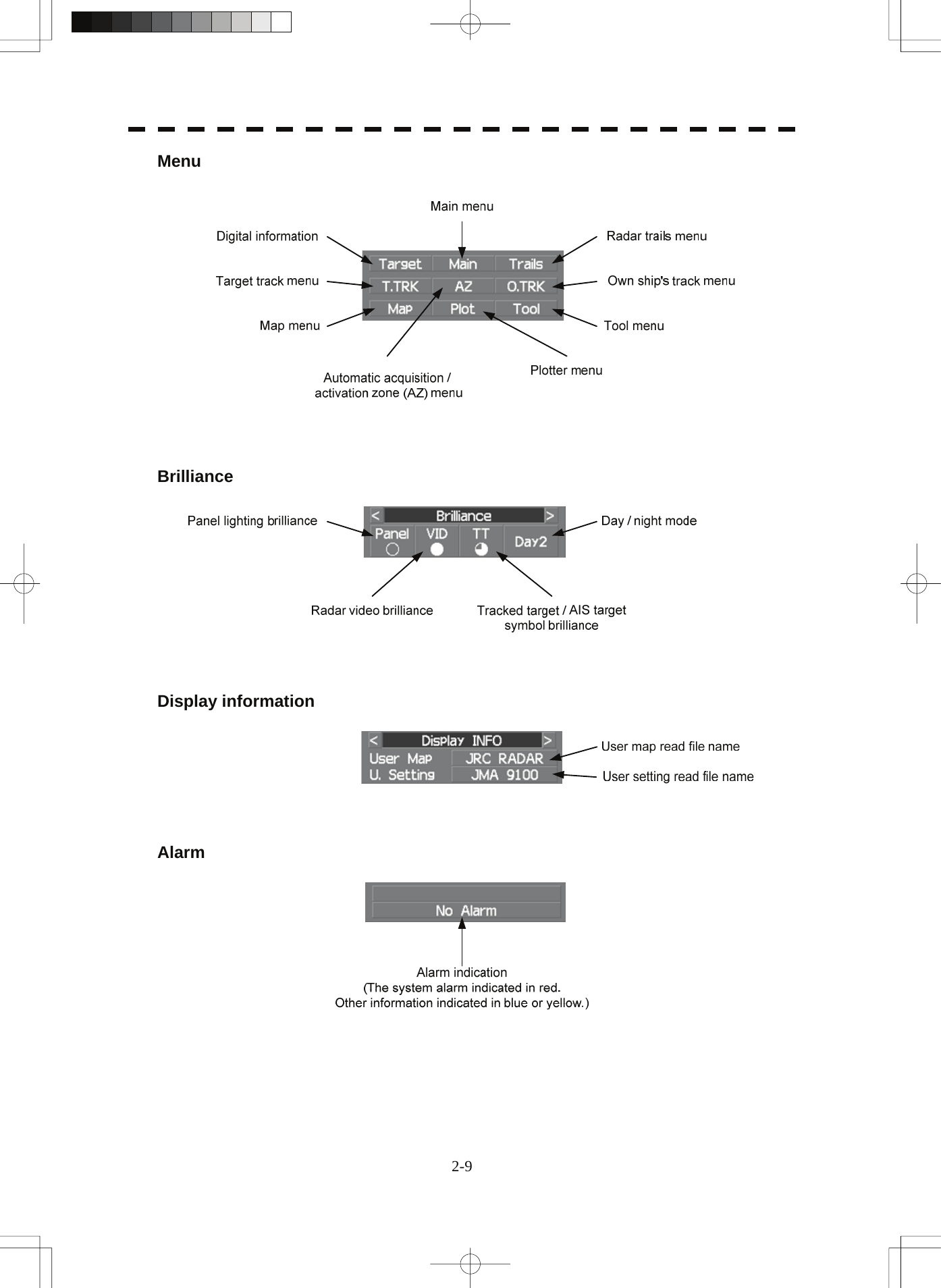
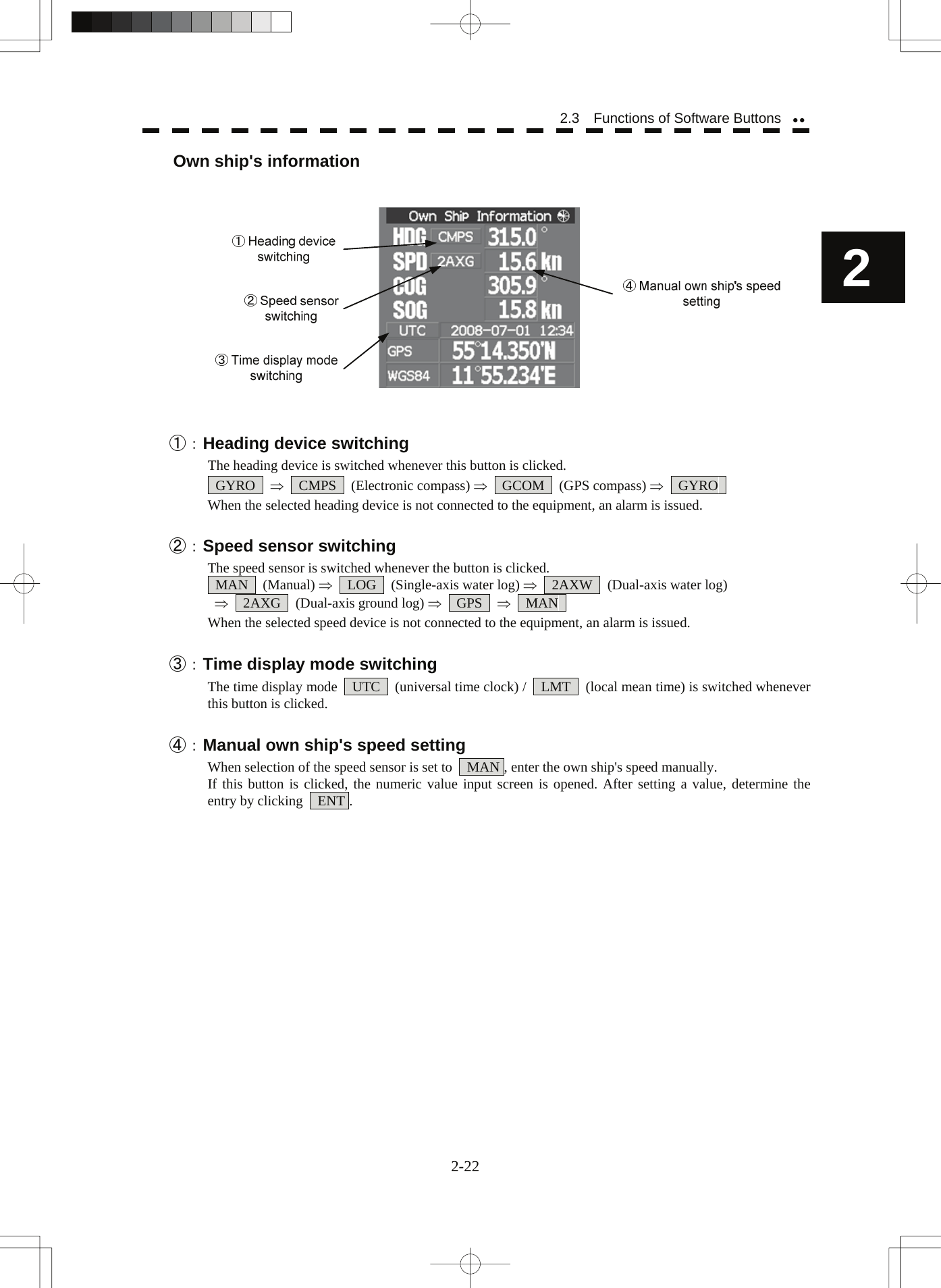
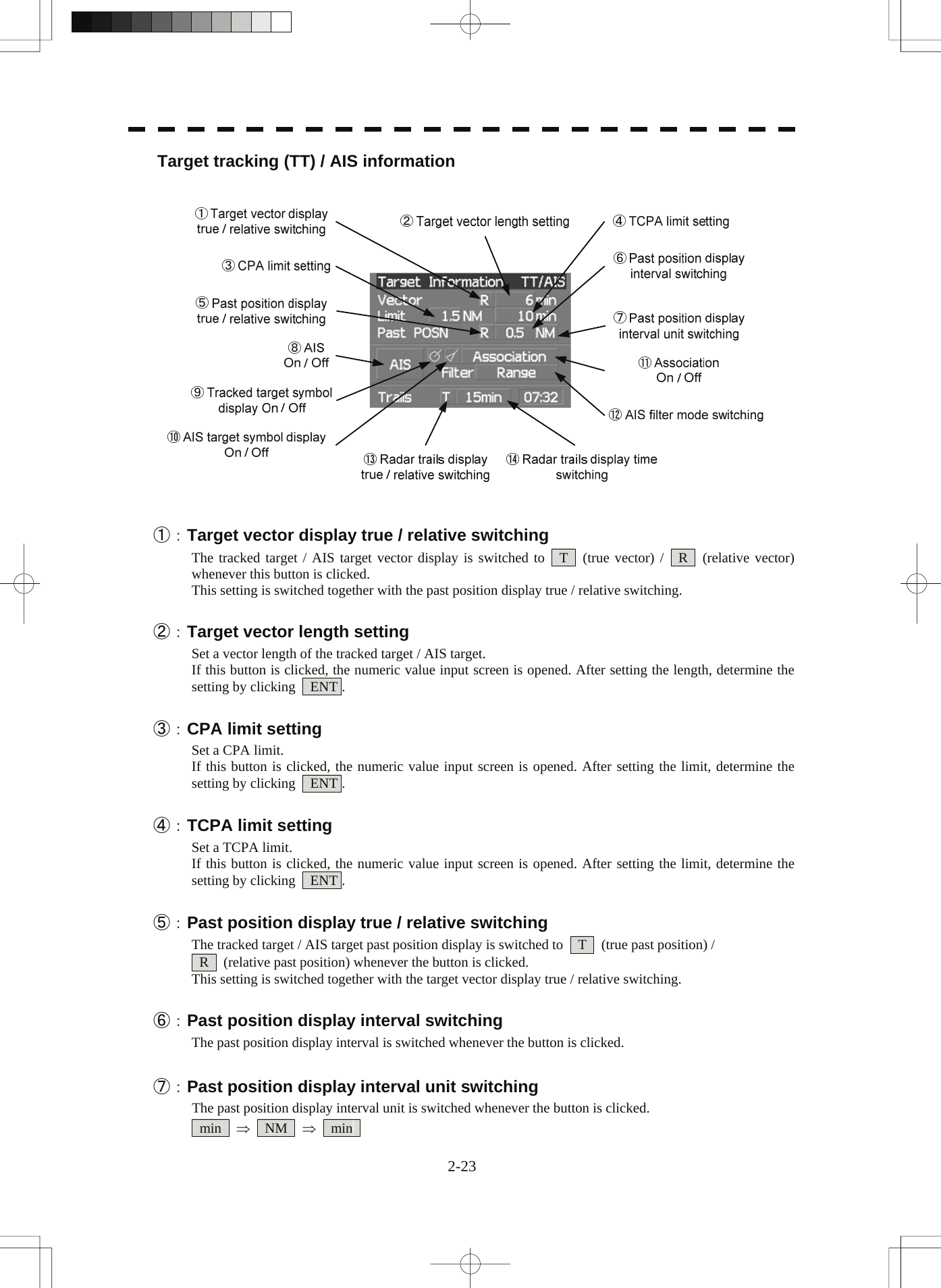
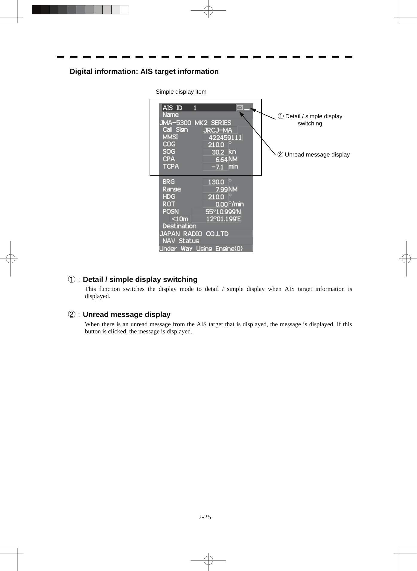
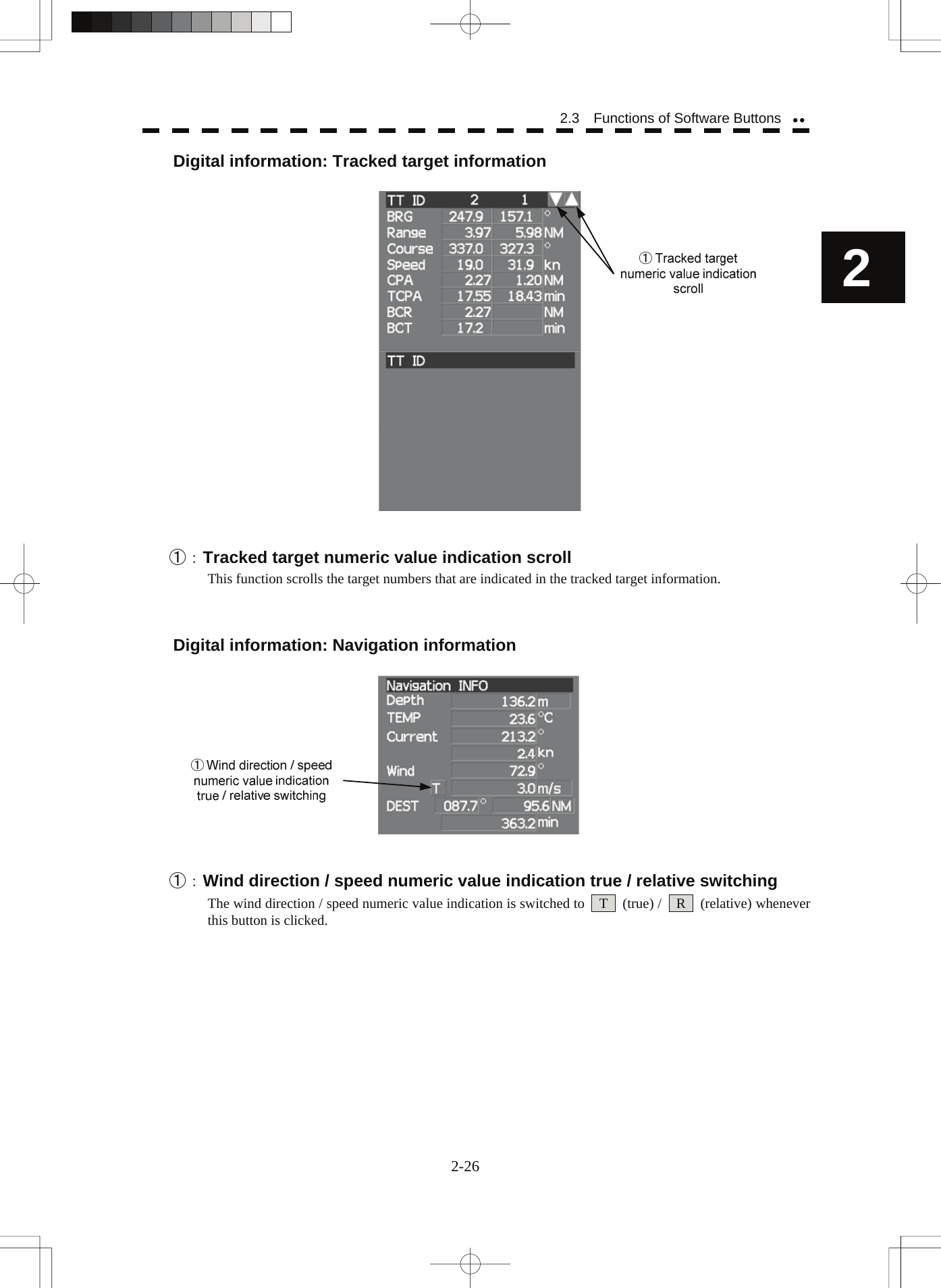
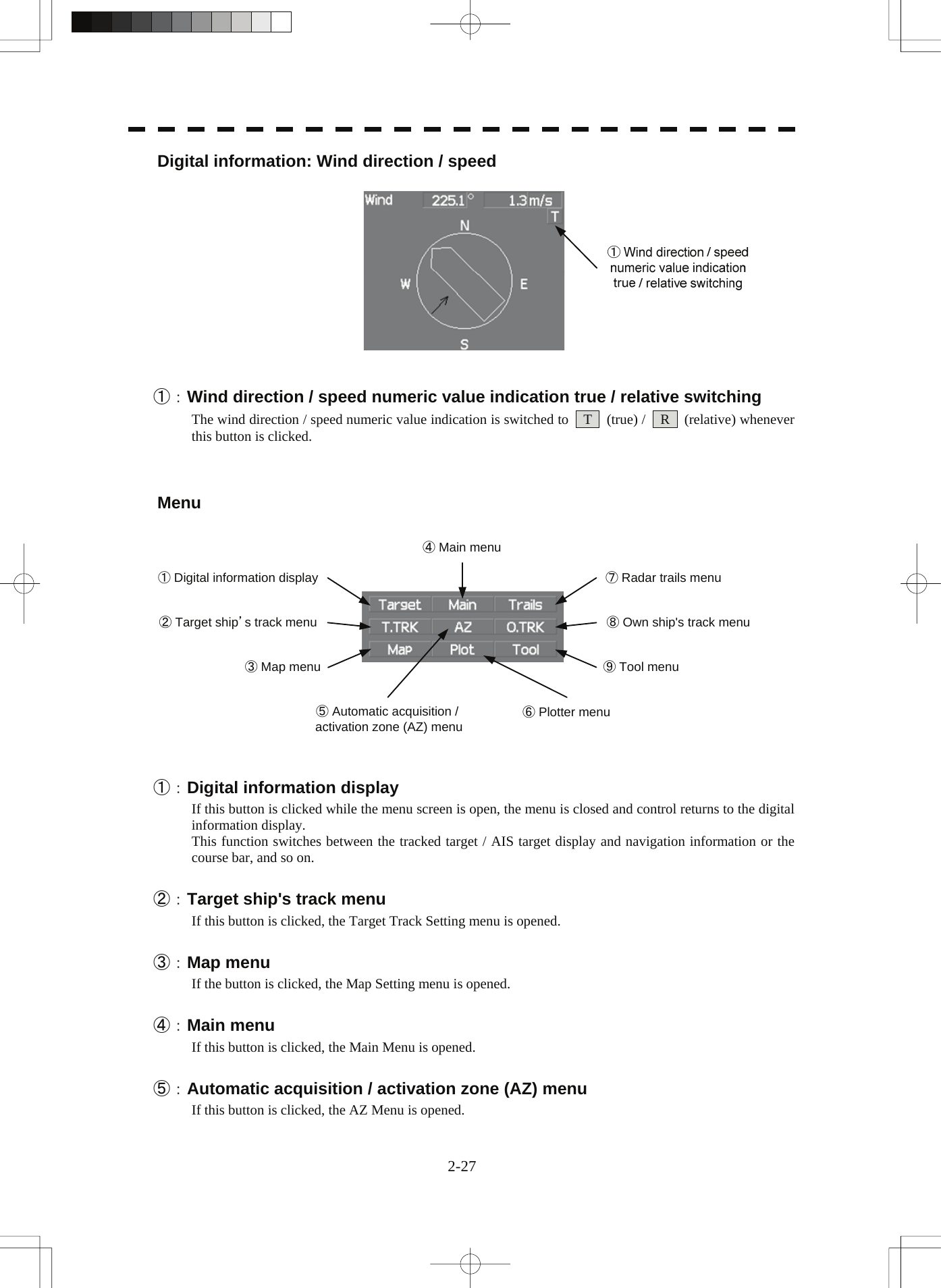
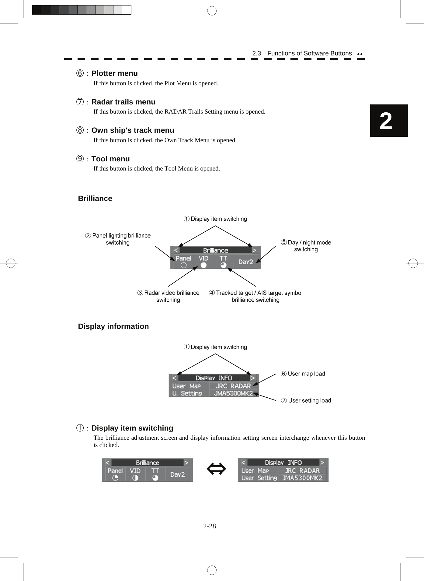
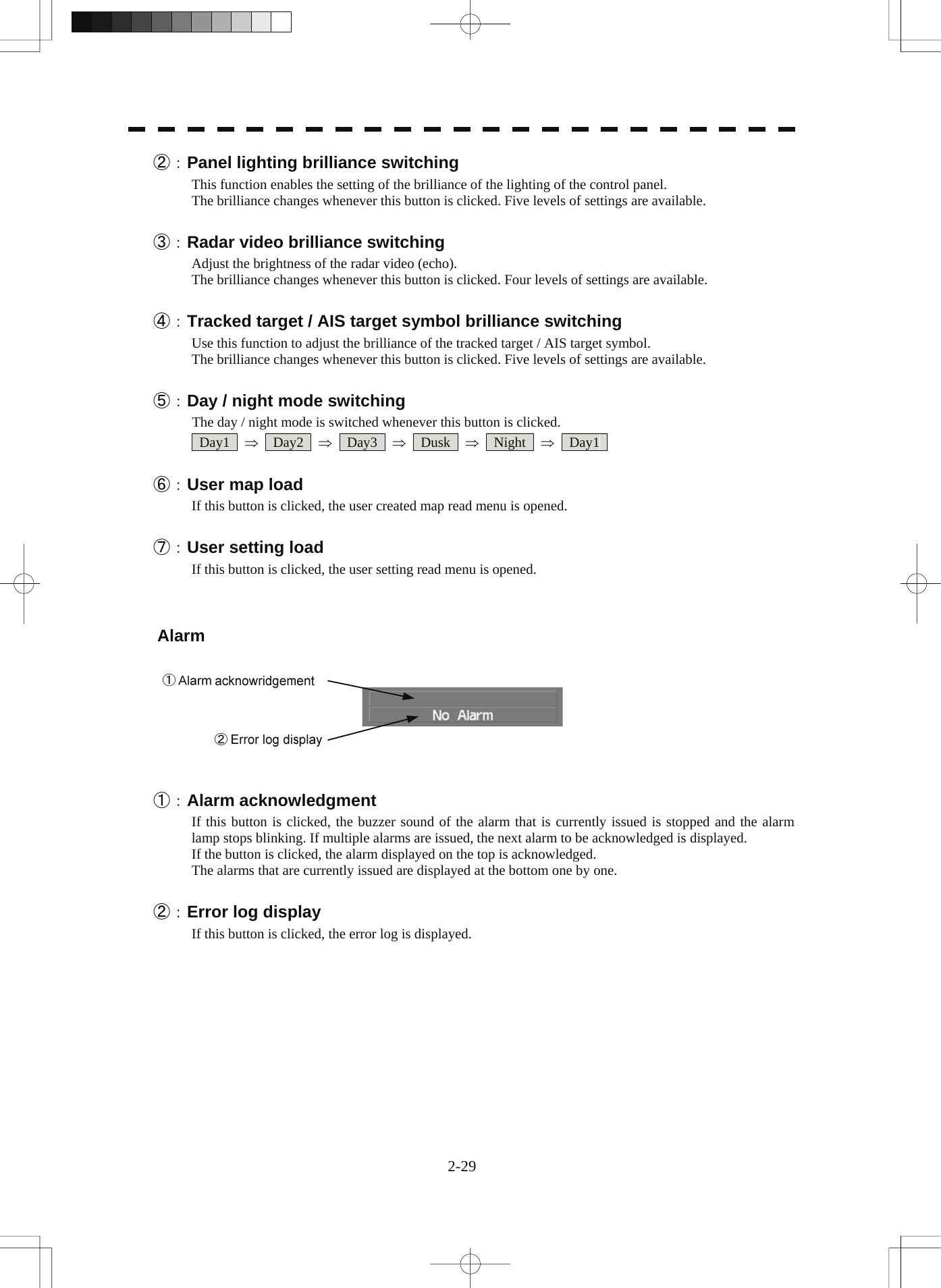
![2.3 FUNCTIONS OF SOFTWARE BUTTONS In this radar, the frequently used functions can be directly set from the screen without opening the menu by using the software buttons on the screen for quick handling. The screen is divided into a number of areas and each area is named. PPIUpper leftof the displayLower leftof the displayUpper rightof the displayLower rightof the displayOwn ship's informationDigital informationTargettracking (TT) /AIS informationMenuBrilliance /Display informationAlarm The name of each button is described from the next page. The function can be used by pressing (clicking) the [ENT] key while setting the arrow cursor on the button position. 2-15](https://usermanual.wiki/Japan-Radio/NKE2103.Users-Manual-1/User-Guide-991971-Page-74.png)
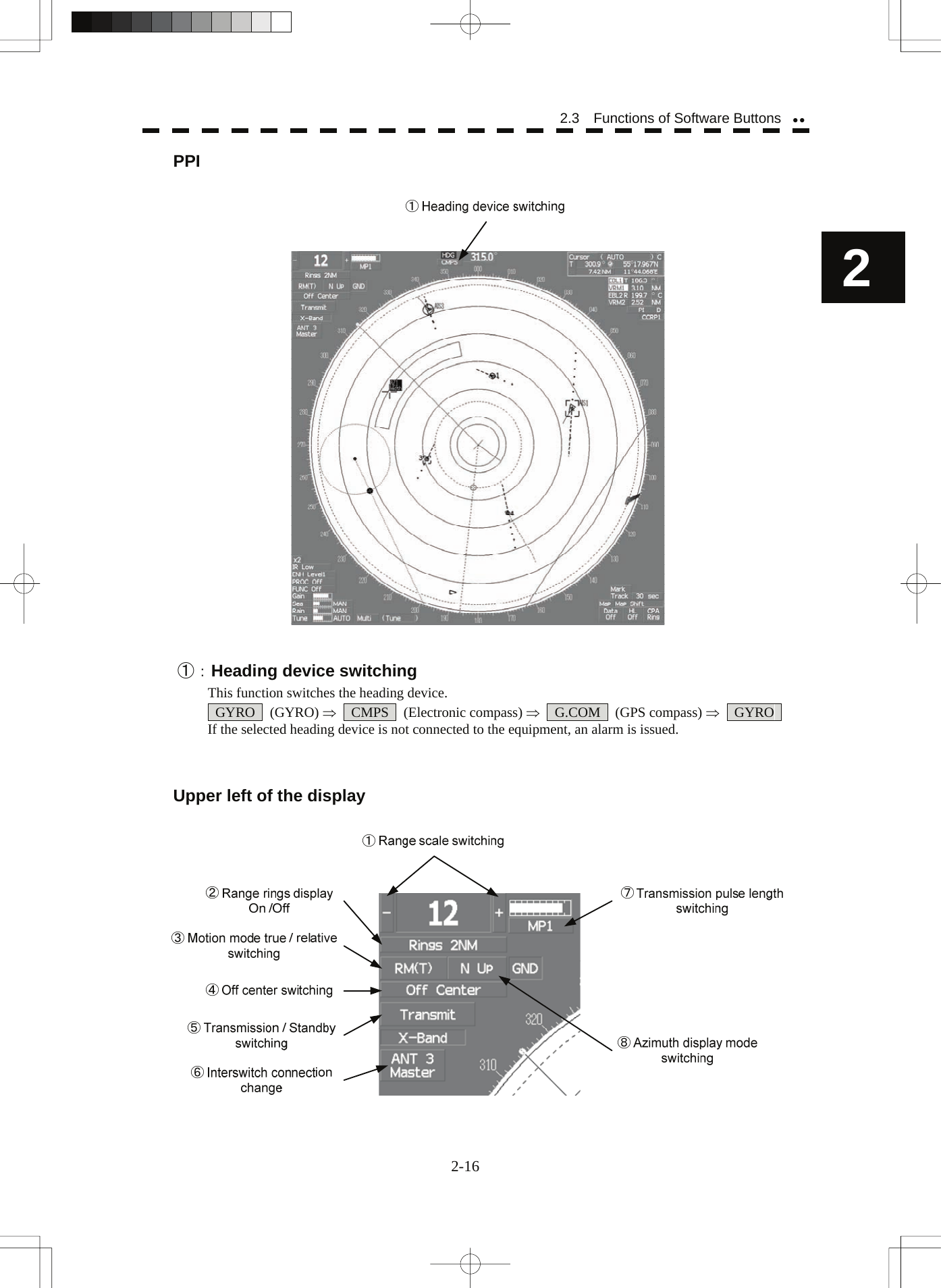
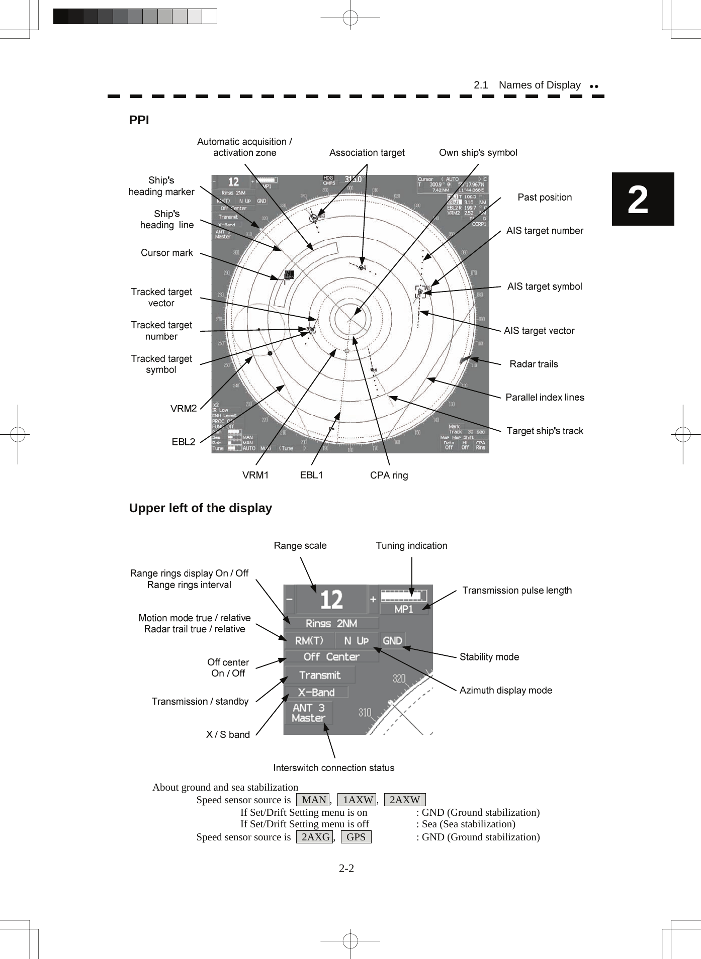
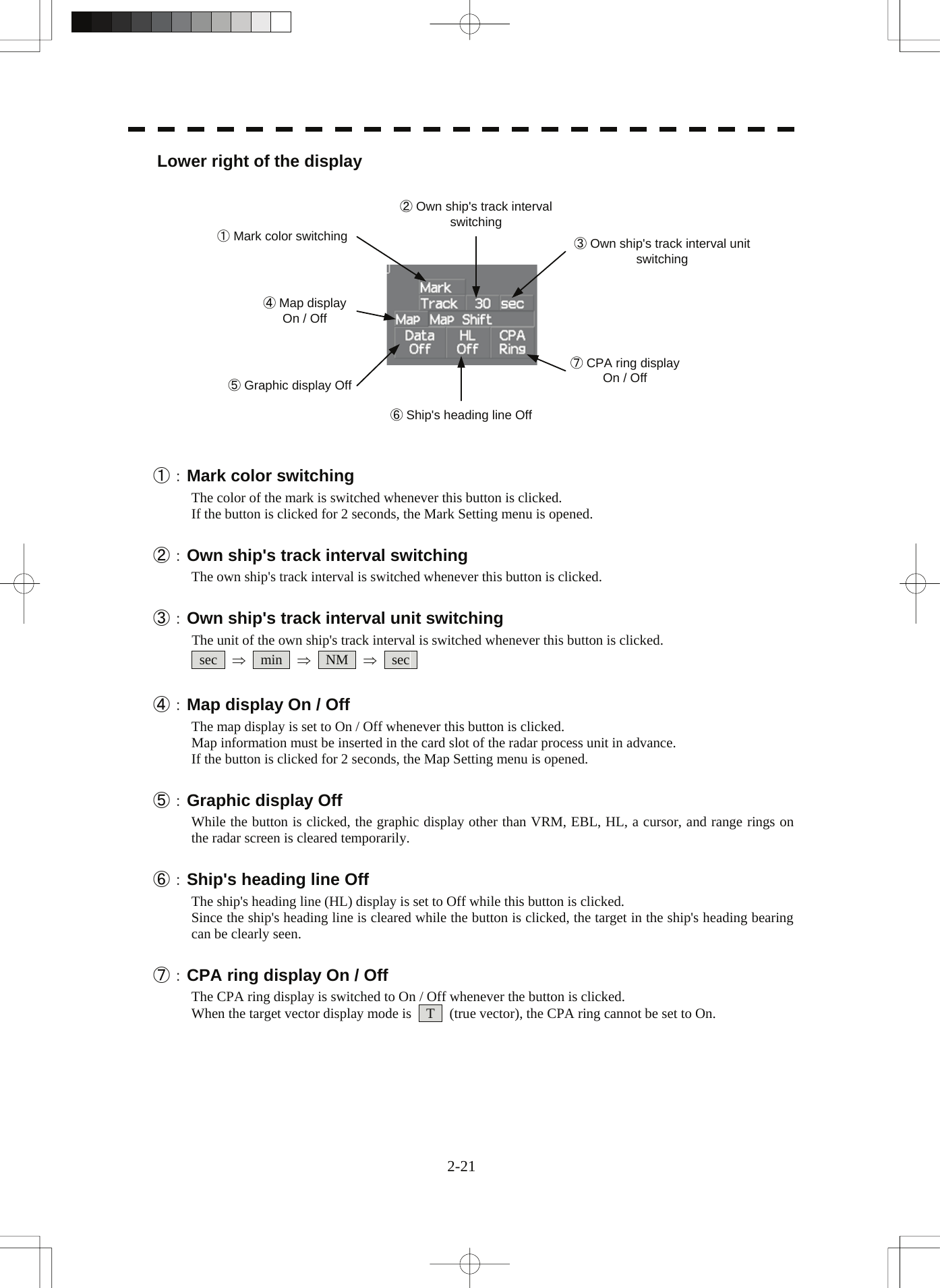
![①:Range scale switching To increase the observation range scale (maximum 96NM), click + and to reduce the range (minimum 0.125NM), click - . ②:Range rings display On / Off The display of range rings are set to On / Off whenever this button is clicked. When the display is set to On, the interval of the fixed range marker is displayed. ③:Motion mode true / relative switching The screen motion mode is switched whenever the button is clicked. TM (true motion) ⇒ RM (relative motion) ⇒ TM RM(R) indicates that the radar trails is a relative trail. RM(T) indicates that the radar trails is a true trail. ④:Off center switching If this button is clicked, the cursor is moved, and the [ENT] key is pressed, the ship's position can be moved to the cursor position. The moving range is within 66% of the radius. If the button is clicked for 2 seconds, the off-center is set to Off and the ship's position is returned to the center of the screen. ⑤:Transmission / standby switching At expiration of the pre-heat time after the power is turned on, Preheat changes to Standby . Standby : Indicates a standby state. If this button is clicked in this state, the equipment is set to a transmission state. Transmit : Indicates a transmission state. If this button is clicked in this state, the equipment is set to a standby state. ⑥:Interswitch connection change This button is displayed when the interswitch is connected. This button indicates the connection status of the scanner unit that is connected to the indicator. If the button is clicked in the transmission standby state, the menu for changing the connection state between the scanner unit and the indicator is displayed. The connection state of the scanner unit and indicator cannot be changed unless the master indicator is in a standby state. → Refer to the Interswitch (Optional) Instruction Manual that is attached for the setting method. This button is not displayed if the interswitch is not connected. ⑦:Transmission pulse length switching The transmission pulse length is switched whenever this button is clicked. Three types of pulses are available, short pulse (SP), middle pulse (MP), and long pulse (LP). The pulse length and repetition frequency vary even for the same short pulse, according to the range that is used and it is displayed as SP1 , SP2 . ⑧:Azimuth display mode switching The azimuth display is switched whenever this button is clicked. H Up (Head Up) ⇒ N Up (North Up) ⇒ C Up (Course Up) ⇒ H Up If the button is clicked for 2 seconds, the GYTO Setting menu is displayed. 2-17](https://usermanual.wiki/Japan-Radio/NKE2103.Users-Manual-1/User-Guide-991971-Page-76.png)
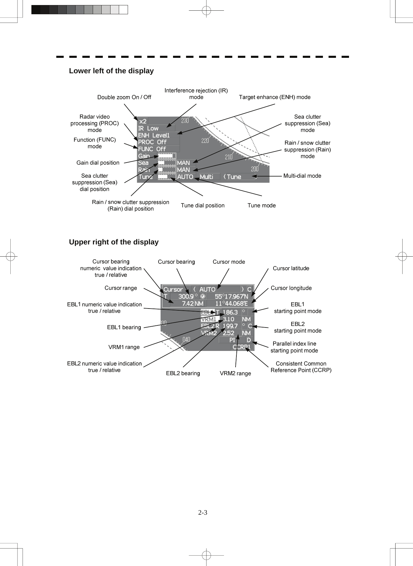
![2.3 Functions of Software Buttons yyLower left of the display 2 ①:Double zoom switching Use this function to enlarge to double the size the display screen of the position specified by the cursor. If this button is clicked, the zoom mode is set. When the cursor is moved to the radar screen and the [ENT] key is pressed, the screen is enlarged to double the size so that the middle of the cursor and the own ship's position is set to the center of the screen. This function cannot be used when the range is 0.125NM. ②:Interference rejection (IR) mode switching The interference rejection mode is switched whenever this button is clicked. IR Off ⇒ IR Low ⇒ IR Medium ⇒ IR High ⇒ IR Off ③:Target enhance (ENH) mode switching The target enhance mode is switched whenever this button is clicked. ENH Off ⇒ ENH Level1 ⇒ ENH Level2 ⇒ ENH Level3 ⇒ ENH Off ④:Radar video processing (PROC) mode switching The radar video processing mode is switched whenever this button is clicked. PROC Off ⇒ 3Scan CORREL ⇒ 4Scan CORREL ⇒ 5Scan CORREL ⇒ ⇒ Remain ⇒ Peak Hold ⇒ PROC Off ⑤:Function (FUNC) mode switching The function mode is switched whenever this button is clicked. FUNC Off ⇒ Coast ⇒ Deep Sea ⇒ Fishnet ⇒ Storm ⇒ FUNC Off If the button is clicked for 2 seconds, the function registration menu (User Function Setting) is opened. ⑥, ⑦, ⑧,and ⑨:Gain, Sea clutter suppression (Sea), Rain / snow clutter suppression (Rain), Tune adjustment Adjust the gain, sea clutter suppression, rain and snow clutter suppression and tune using the track ball. If the button is clicked on, the adjustment value is shown at the upper-right of the cursor. Make adjustments by moving the track ball to the left and right. Determine the adjustment by pressing the [ENT] key. 2-18](https://usermanual.wiki/Japan-Radio/NKE2103.Users-Manual-1/User-Guide-991971-Page-77.png)
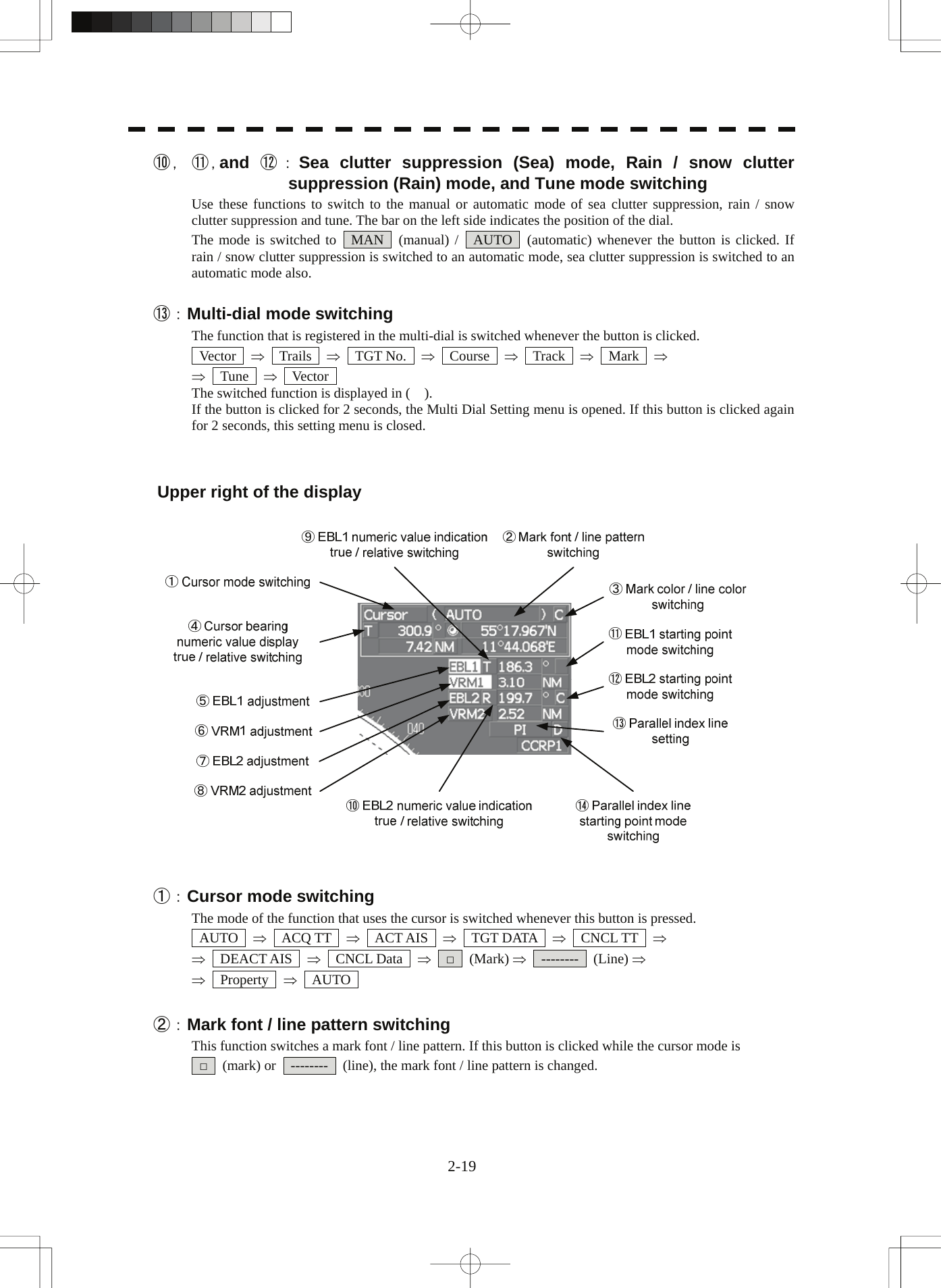
![2.3 Functions of Software Buttons yy③:Mark color / line color switching This function switches a mark color / line color. If this button is clicked while the cursor mode is □ (mark) or -------- (line), the mark color / line color is changed. 2 ④:Cursor bearing numeric value display true / relative switching The bearing numeric value display T (true bearing) / R (relative bearing) of the cursor is switched whenever this button is clicked. ⑤, ⑥, ⑦,and ⑧:EBL1 / 2 and VRM1 / 2 adjustment These functions set the EBL1 , VRM1 , EBL2 , and VRM2 displays to On / Off and acquire the operation right. If the button is clicked on, the operation right is acquired. Make adjustments by moving the track ball to the left and right Determine the adjustment by pressing the [ENT] key. ⑨ and ⑩:EBL1, EBL2 numeric value true / relative switching The EBL1 / 2 bearing numeric value display T (true bearing) / R (relative bearing) is switched whenever the button is clicked. If the button is clicked for 2 seconds, the EBL / Cursor Setting menu is displayed. ⑪ and ⑫:EBL1 / EBL2 starting point mode switching The EBL starting point is set to CCRP or any position on the radar screen whenever this button is clicked. ⇒ C ⇒ D ⇒ : Center :The starting point is fixed to the CCRP position. C : Screen Fix :The starting point is set to the cursor position. If the [ENT] key is pressed subsequently, the starting position is fixed to the cursor position. D : L/L Fix :The starting point is set to the cursor position. If [ENT] key is pressed subsequently, the starting position is fixed to the latitude / longitude of the cursor. (Connection of a navigator is necessary.) If the starting point is moved outside of the screen, the operation is reset automatically and the starting point returns to the CCRP position. * D is enabled only when a navigator is connected. ⑬:Parallel index line setting This function sets the parallel index line display to On / Off and acquires the operation right. If this button is clicked, the operation right is acquired and the menu is opened. After setting, determine the setting by pressing the [ENT] key. ⑭:Parallel index line starting point mode switching The parallel index line starting point is set to CCRP or any position on the radar screen whenever this button is clicked. In the same way as for the EBL starting point, three options are available, : Center, C : Screen Fix, and D : L/L Fix. 2-20](https://usermanual.wiki/Japan-Radio/NKE2103.Users-Manual-1/User-Guide-991971-Page-79.png)
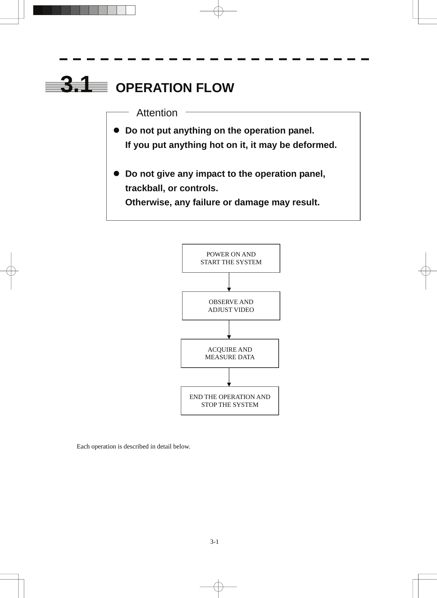
![SECTION 3 BASIC OPERATION 3.1 OPERATION FLOW................................................................................3-1 3.2 OBSERVE AND ADJUST VIDEO...........................................................3-5 3.3 OPERATION PROCEDURES...............................................................3-11 3.4 GENERAL RADAR OPERATION.........................................................3-21 3.5 USE OWN SHIP'S TRACK DATA.........................................................3-49 3.6 DISPLAY USER MAP ...........................................................................3-54 3.7 USE ROUTE FUNCTION......................................................................3-78 3.8 APPLIED OPERATIONS ......................................................................3-79 3.9 USE FUNCTION KEY [FUNC]..............................................................3-94 3.10 USE USER SETTING .........................................................................3-100 3.11 USING CARD......................................................................................3-102 3.12 DISPLAY SIMPLE CHART.................................................................3-108](https://usermanual.wiki/Japan-Radio/NKE2103.Users-Manual-1/User-Guide-991971-Page-89.png)
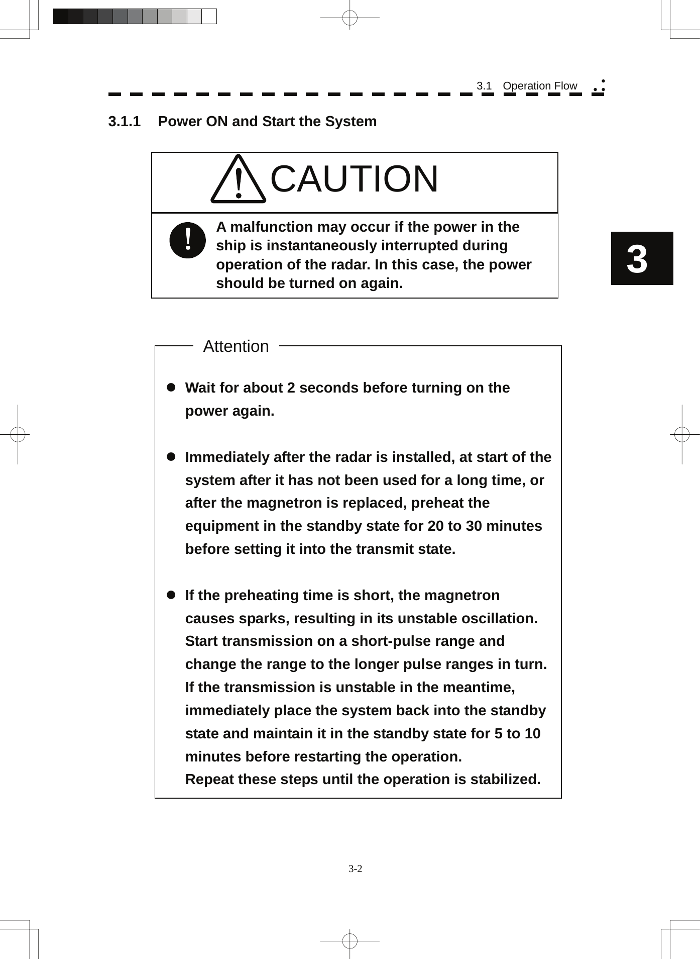
![Procedures 1 Check that the ship’s mains are turned on. 2 Press the [STBY] key. The system is turned on, and the preheating time is displayed. Preheat is indicated upper left of the display. 3 Wait until the preheating time is over. When the preheating time is over, the preheating time screen disappears, and Preheat upper left of the display changes to Standby . 4 Press the [TX / PRF] key. The radar will start transmission and the antenna will start rotating. Standby upper left of the display changes to Transmit . Note: The radar does not start transmission if you Press the [TX / PRF] key while Preheat is indicated. 3.1.2 Observe and Adjust Video Procedures 1 Press the [RANGE+] key or [RANGE-] key to set the range to the scale required for target observation. 2 Turn the dials [GAIN / PL], [AUTO-SEA], and [AUTO-RAIN] to obtain the clearest targets. Refer to [GAIN/PL]→3-7P [AUTO-SEA]→3-7P [AUTO-RAIN]→3-9P for how to use each dial. For how to adjust video, see Chapter 3.2. 3.1.3 Acquire and Measure Data For details on how to acquire data and measure, see Section 4 "Measurement of range and bearing." 3.1.4 Display and Measure with Reference to CCRP The radar video, range, bearing, Target Tracking and AIS data display etc... are displayed with reference to CCRP (Consistent Common Reference Point). If scanner is switched, these data are measured from CCRP. If some kind of functions set scanner position to outside of the PPI range, these data except Target Tracking and AIS data are displayed with reference to scanner position. For how to setting CCRP, see the section 7.1.9. 3-3](https://usermanual.wiki/Japan-Radio/NKE2103.Users-Manual-1/User-Guide-991971-Page-92.png)
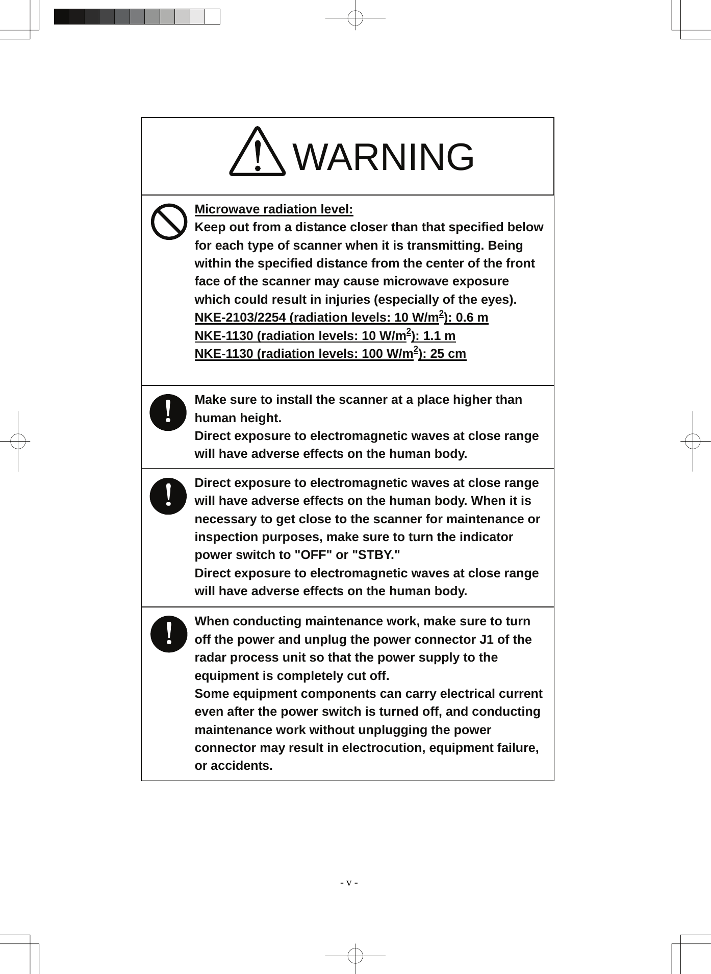
![3 3.1 Operation Flow yy y3.1.5 End the Operation and Stop the System Exit 1 Press the [STBY] key. The radar will stop transmission and the antenna will stop rotating. Transmit upper left of the display changes to Standby . Maintain the standby state if radar observation is restarted in a relatively short time. Only pressing the [TX / PRF] key starts observation. 2 Press the [STBY] key and the [TX / PRF] key together. The system will be turned off. WARNING Some equipment components can carry electrical current even after the power switch is turned off, and conducting maintenance work without unplugging the power connector may result in electrocution, equipment failure, or accidents. When conducting maintenance work, make sure to turn off the power and unplug the power connector J1 of the radar process unit so that the power supply to the equipment is completely cut off. 3-4](https://usermanual.wiki/Japan-Radio/NKE2103.Users-Manual-1/User-Guide-991971-Page-93.png)
![3.2 OBSERVE AND ADJUST VIDEO 3.2.1 Adjust Monitor Brilliance [BRILL] Procedures 1 Obtain the best-to-see display with optimum brilliance by turning the [BRILL] dial at the lower right of the LCD monitor. Turning the [BRILL] dial clockwise increases the brilliance of the entire display. Conversely, turning the [BRILL] dial counterclockwise decreases the brilliance of the entire display. In consideration of the ambient brightness, adjust display brilliance that is high enough to easily observe the radar display but does not glare. 3.2.2 Change Observation Range [RANGE + / - ] Procedures 1 When increasing the observation range, press the [RANGE+] key. Increasing the observation range will enable a wider range to be observed. However, a video image is small and the ability to detect targets near own ship decreases. Therefore, when observing the vicinity of own ship, use the smaller observation range. 2 When decreasing the observation range, press the [RANGE-] key. Decreasing the observation range will enable the vicinity of own ship to be enlarged. However, caution must be taken because video images of the area beyond the observation range cannot be displayed. 3-5](https://usermanual.wiki/Japan-Radio/NKE2103.Users-Manual-1/User-Guide-991971-Page-94.png)
![3 3.2 Observe and Adjust Video yy y3.2.3 Tune CAUTION Normally, use the automatic tune mode. Use the manual tune mode only when best tuning is not possible in the automatic tune mode due to deterioration of magnetron. This radar system provides the automatic tune mode and the manual tune mode. The automatic tune mode automatically adjusts the tuning of the transmitting frequency and the receiving frequency, and the manual tune mode enables tuning to be adjusted by using the dial located on the operation unit. The tune mode currently being used is displayed in the tune mode switching (lower left of the display ⑫ on page 2-18). When using the automatic tune mode Procedures 1 Put the cursor on the tune mode switching (lower left of the display ⑫ on page 2-18) and press the [ENT] key. The automatic tune mode is selected and AUTO is displayed in the tune mode field. Tune adjustment is automatically conducted. Tune is adjusted at the start of transmission, at the change of the range or pulse length. Tune adjustment is completed within several seconds. When using the manual tune mode Procedures 1 Put the cursor on the tune mode switching (lower left of the display ⑫ on page 2-18) and press the [ENT] key to set the manual tune mode. The automatic tune mode is cancelled, and MAN is displayed in the tune mode field. 2 Press the [MULTI] dial to set the ( Tune ) mode. Tune is displayed in the multi-dial mode (lower left of the display on page 2-3). 3 Turn the [MULTI] dial to adjust tune. Make adjustments so that the tuning indication (upper left of the display on page 2-2) indicates the maximum. 3-6](https://usermanual.wiki/Japan-Radio/NKE2103.Users-Manual-1/User-Guide-991971-Page-95.png)
![3.2.4 Adjust Gain [GAIN / PL] CAUTION On the contrary, if the gain is too low, targets including ships and dangerous objects may not be clearly indicated. If the gain is too high, unnecessary signals including receiver noise and false video increase resulting in reduction of visibility of targets. Procedures 1 Adjust noise of the display by turning the [GAIN / PL] dial until targets can be easily observed. Turning [GAIN / PL] dial clockwise increases gain. Turning [GAIN / PL] dial counterclockwise decreases gain. By increasing receiving gain, the range to observe radar video is widened. To observe densely crowded targets or short-range targets, reducing the receiving gain will enable the targets to be easily observed. 3-7](https://usermanual.wiki/Japan-Radio/NKE2103.Users-Manual-1/User-Guide-991971-Page-96.png)
![3 3.2 Observe and Adjust Video yy y3.2.5 Suppress Sea Clutter [AUTO-SEA] CAUTION When using the sea clutter suppression function, never set the suppression level too high canceling out all image noises from the sea surface at close range. Detection of not only echoes from waves but also targets such as other ships or dangerous objects will become inhibited. When using the sea clutter suppression function, make sure to choose the most appropriate image noise suppression level. Using the manual sea clutter suppression mode Procedures 1 Adjust the sea clutter returns of the display by turning the [AUTO-SEA] dial until targets can be easily observed. Turning [AUTO-SEA] dial clockwise suppresses sea clutter returns. Turning [AUTO-SEA] dial counterclockwise intensifies sea clutter returns. The sea clutter suppression function suppresses sea clutter returns by decreasing the receiving gain on a short range. Turning the [AUTO-SEA] dial clockwise heightens the effect of sea clutter suppression. However, be careful that excessive suppression causes low signal-strength targets such as buoys and boats to disappear from the radar display. 3-8](https://usermanual.wiki/Japan-Radio/NKE2103.Users-Manual-1/User-Guide-991971-Page-97.png)
![Using the automatic sea clutter suppression mode The sea clutter suppression in accordance with the intensity of sea clutter is possible. Use this mode when the sea clutter's intensity differs according to directional orientation. Procedures 1 Press the [AUTO-SEA] dial. The automatic sea clutter suppression mode is selected, and AUTO is displayed in sea clutter suppression (Sea) mode switching (lower left of the display ⑩ on page 2-18). 2 Make adjustments by turning the [AUTO-SEA] dial. Even when the automatic sea clutter suppression mode is selected, turning the [AUTO-SEA] dial can make fine adjustments manually. Note: When the automatic sea clutter suppression mode is selected, the automatic rain/snow suppression mode is switched to the manual mode. To select both the sea clutter suppression function and the rain/snow suppression function in the automatic mode, use the automatic rain/snow suppression mode. Cancellation 1 Press the [AUTO-SEA] dial. The automatic sea clutter suppression mode is cancelled, and MAN is displayed in the sea clutter suppression (Sea) mode field. 3.2.6 Suppress Rain / Snow Clutter [AUTO-RAIN] CAUTION When using the rain clutter suppression function, make sure to choose the most appropriate image noise suppression level. When using the rain clutter suppression function, never set the suppression level too high canceling out all image noises from the rain or snow at the close range. Detection of not only echoes from the rain or snow but also targets such as other ships or dangerous objects will become inhibited. 3-9](https://usermanual.wiki/Japan-Radio/NKE2103.Users-Manual-1/User-Guide-991971-Page-98.png)
![3 3.2 Observe and Adjust Video yy yUsing the manual rain / snow clutter suppression mode Procedures 1 Adjust the rain / snow clutter returns of the display by turning the [AUTO-RAIN] dial until targets can be easily observed. Turning [AUTO-RAIN] dial clockwise suppresses rain / snow clutter returns. Turning [AUTO-RAIN] dial counterclockwise intensifies rain / snow clutter returns. When the [AUTO-RAIN] dial is turned clockwise, the rain / snow clutter suppression function suppresses rain / snow clutter returns and gets targets hidden by rain / snow clutter returns to appear of the display. However, be careful that excessive suppression may cause small targets to be overlooked. Since the rain / snow clutter suppression function also has the effect of suppressing sea clutter, the suppression efficiency improves when the [AUTO-RAIN] dial is used with the [AUTO-SEA] dial. In general, turn the [AUTO-RAIN] dial fully to the left. Using the automatic rain / snow clutter suppression mode The rain / snow clutter suppression in accordance with the intensity of rain / snow clutter is possible. Use this mode when the rain / snow clutter's intensity differs according to directional orientation. Procedures 1 Press the [AUTO-RAIN] dial. The automatic rain / snow clutter suppression mode is selected, and AUTO is displayed in the sea clutter suppression (Sea) mode switching and the rain / snow clutter suppression (Rain) mode switching ( lower left on the display ⑩ and ⑪ on page 2-18) 2 Make adjustments by turning the [AUTO-RAIN] dial and the [AUTO-SEA] dial. Even when the automatic rain / snow clutter suppression mode is selected, turning the [AUTO-RAIN] dial and the [AUTO-SEA] dial can make fine adjustments manually. Note: When the automatic rain / snow clutter suppression mode is selected, the automatic sea clutter suppression mode is also activated. It is not possible to set only the rain / snow clutter suppression function to the automatic mode. Cancellation 1 Press the [RAIN] dial. The automatic rain / snow clutter suppression mode is cancelled, and AUTO is changed to MAN in the sea clutter suppression (Sea) mode field and the rain / snow clutter suppression (Rain) mode field. 3.2.7 Reset Alarm Buzzer [ALARM ACK] When an audible alarm is issued, use [ALARM ACK] to acknowledge the alarm information, stop the alarm buzzing, and stop the alarm lamp flashing. (If more than one alarm has occurred, press the key for each alarm indication.) The alarm stops buzzing, but the alarm indication does not disappear. Procedures 1 Press the [ALARM ACK] key. The alarm will stop buzzing. 3-10](https://usermanual.wiki/Japan-Radio/NKE2103.Users-Manual-1/User-Guide-991971-Page-99.png)
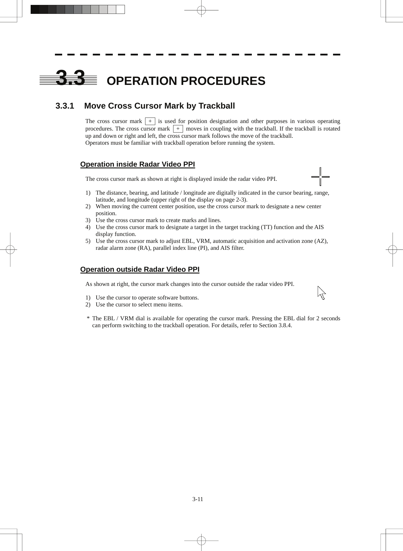
![3 3.3 Operation Procedures yy y3.3.2 Operate Software Buttons Software buttons are provided of the display so as to easily switch functions without operating menu items. For software buttons that can be operated and their locations, see Chapter 2. Procedures 1 Put the pointer on the software button of the display. The software button indicated by the cursor will be shown in reverse video, which indicates that the button is specified. 2 Press the [ENT] key. The operating state changes according to the function of the software button. On / off settings Each time the [ENT] key is pressed, the operating state switches as follows: On ⇒ Off ⇒ On ⇒ Off Multiple settings For example, each time the [ENT] key is pressed, the operating state switches as follows: IR Off ⇒ IR Low ⇒ IR Middle ⇒ IR High ⇒ IR Off 3-12](https://usermanual.wiki/Japan-Radio/NKE2103.Users-Manual-1/User-Guide-991971-Page-101.png)
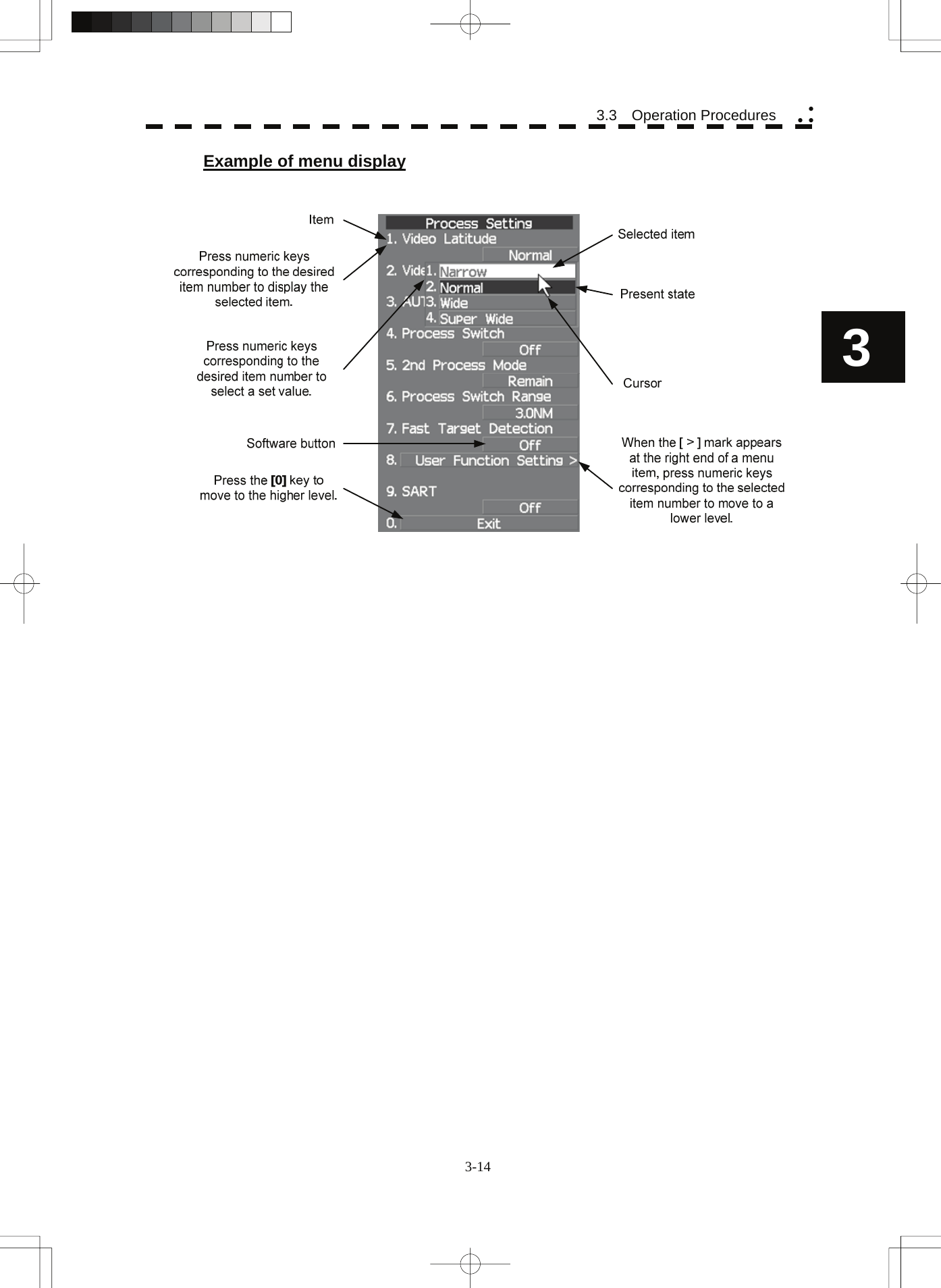
![3.3.3 Basic Menu Operation To open the menu: Put the cursor on main menu Main (Menu ④ on page 2-27) and press the [ENT] key, and the main menu will open. Alternatively, press the [RADAR MENU] key. By putting the cursor on Target , Map , or AZ adjacent to Main and pressing the [ENT] key, the menu exclusive for the function will open. For the arrangement of software buttons, see Chapter 2. To close the menu: Put the cursor on digital information display Target (Menu ① on page 2-27) and press the [ENT] key, and the menu will close and the digital information display screen will appear. Alternatively, press the [0] key until the menu will close. To move to a lower level of the menu: The menu is in hierarchical structure. Put the cursor on the desired menu item and press the [ENT] key, and control will move to the lower level. Alternatively, Press numeric keys corresponding to the desired menu item number, and the > mark will appear at the right end of a menu item having a lower level. To move to a higher level of the menu: Put the cursor on 0. Exit located lower of the menu when the menu is open. Control will return to the higher level. Alternatively, press the [0] key. To determine an item: Put the cursor on the menu item you want to change and press the [ENT] key. The selected item will be displayed. Alternatively, Press numeric keys corresponding to the desired item number. To determine the selected item: Put the cursor on the desired item and then press the [ENT] key. The selected item will be determined. Alternatively, Press numeric keys corresponding to the selected item number. If you do not change the setting of the selected item, press the [CLR / INFO] key. The selected item will be closed without changing the settings. 3-13](https://usermanual.wiki/Japan-Radio/NKE2103.Users-Manual-1/User-Guide-991971-Page-102.png)
![3.3.4 Operation on Numeric Value, Latitude / Longitude and Character Input menu When a numeric value, latitude / longitude, or character must be entered during operation, the input screen will appear. Enter a numeric value, latitude / longitude, or character according to the procedures below. Numeric value input menu Directly entering a numeric value Procedures 1 On the numeric value input menu, sequentially press numeric keys to enter a desired numeric value. For example, when entering 123.4° for a bearing value, sequentially press the keys as follows: [1] →[2] →[3] →[4] 2 Make sure that the entered value is correct, put the cursor on ENT , and then press the [ENT] key. The set value is reflected to the operating state. 3 To cancel input, put the cursor on CLR , and then press the [ENT] key. The numeric value input menu will close without reflecting the set value to the operating state. 3-15](https://usermanual.wiki/Japan-Radio/NKE2103.Users-Manual-1/User-Guide-991971-Page-104.png)
![3 3.3 Operation Procedures yy yIncreasing or decreasing a numeric value Procedures 1 On the numeric value input menu, put the cursor on + or - , and then press the [ENT] key to increase or decrease numeric value so as to change to the desired numeric value. For example, to change bearing value of 123.0° to 123.4°, put the cursor sequentially on + located on the software numeric value input menu, and then press the [ENT] key four times. * Turning the [MULTI] dial will conduct the same operation. 2 Make sure that the entered value is correct, put the cursor on ENT , and then press the [ENT] key. The set value is reflected to the operating state. 3 To cancel input, put the cursor on CLR , and then press the [ENT] key. The numeric value input menu will close without reflecting the set value to the operating state. 3-16](https://usermanual.wiki/Japan-Radio/NKE2103.Users-Manual-1/User-Guide-991971-Page-105.png)
![Latitude / longitude input screen Entering latitude / longitude Procedures 1 On the latitude / longitude input menu, sequentially press numeric keys to enter latitude (XX°XX.XXX'). For example, to enter 12°34.567', sequentially press numeric keys as follows. [1] →[2] →[3] →[4] →[5] →[6] →[7] 2 To make change between north latitude and south latitude, use + and - . North latitude: Put the cursor on + and then press the [ENT] key. South latitude: Put the cursor on - and then press the [ENT] key. 3 Put the cursor on ENT and then press the [ENT] key. The manually entered latitude value is determined. Then, enter the longitude value. 4 Sequentially press numeric keys to enter longitude (XXX°XX.XXX'). 5 To make change between east longitude and west longitude, use + and - . East longitude: Put the cursor on + and then press the [ENT] key. West longitude: Put the cursor on - and then press the [ENT] key. 6 Put the cursor on ENT and then press the [ENT] key. The manually entered longitude value is determined. 3-17](https://usermanual.wiki/Japan-Radio/NKE2103.Users-Manual-1/User-Guide-991971-Page-106.png)
![3 3.3 Operation Procedures yy y 7 To cancel input, put the cursor on CLR and then press the [ENT] key. The latitude / longitude input menu will close without reflecting the set value to the operating state. Character input screen Enter buttonBack Space buttonDelete buttonCharacter/Number button Entered characterExit button Entering a character Procedures 1 On the character input menu, use trackball to select alphabet from A to Z, numbers from 0 to 9, or symbols (only comments for mark / line), and then press the [ENT] key to enter one character of the name to be inputted. For example, JRC for a name, click button as follows: J → R → C 2 Make sure that the entered character is correct, put the cursor on ENT , and then press the [ENT] key. The character has been entered. 3 To cancel input, put the cursor on Exit , and press the [ENT] key. The character input menu will be closed without entering the character. 3-18](https://usermanual.wiki/Japan-Radio/NKE2103.Users-Manual-1/User-Guide-991971-Page-107.png)
![3.3.5 Overview of Menu Structure The menu structure of this radar system consists of seven frequently used function menus, one main menu, and one service man menu used for the installation settings. Software buttons for opening those menus are displayed in the menu area. For each menu item and structure, see the menu list in the appendix. To prevent incorrect use, enter the special code to open the service man menu. For operating the service man menu, see Chapter 7. Frequently used functions Trails Used for operating and setting the radar trails function. T.TRK Used for operating and setting the target track function. AZ Used for operating and setting the automatic acquisition / activation function. O.TRK Used for operating and setting the own ship track function. Map Used for operating and setting the map function. Plot Used for operating and setting the plotter function. Tool Used for operating and setting the navigation tool functions. Main menu Main Used for operating and setting the functions other than the above. Service man menu This menu is used for operation and settings when a system is installed. It is not used during normal operation. The special code must be entered to open the service man menu. 3.3.6 Operate Multi-Dial [MULTI] The [MULTI] dial is provided to change the settings of parameters such as the length of radar trails. Radar operation is simplified by using the [MULTI] dial. [I] Initial Setting (Multi Dial Setting) Set parameters that can be operated with the multi-dial. Procedures 1 Press the [MULTI] dial for 2 seconds. The Multi Dial Setting menu will appear. 3-19](https://usermanual.wiki/Japan-Radio/NKE2103.Users-Manual-1/User-Guide-991971-Page-108.png)
![3 3.3 Operation Procedures yy y 2 Press numeric keys corresponding to the desired item number. On and off functions of the item are switched. On : Operation is conducted by the [MULTI] dial. Off : Operation is not conducted by the [MULTI] dial. Items set to On can be opened by pressing the [MULTI] dial. Item overview Vector Length : The vector length of tracked target and activate AIS target is adjusted. Trails Length : The radar trails length is adjusted. TT Display No. : The target numbers of tracked target to be displayed are switched. C-Up Angle : The course in the course up mode is adjusted. Mark/Line Color : Mark / line colors are switched. Manual Tune : Tune in the manual tune mode is adjusted. [II] Using Multi-dial Procedures 1 Press the [MULTI] dial to select the parameter whose setting is to be changed. The multi-dial modes are switched. Vector ⇒ Trails ⇒ TGT No. ⇒ Course ⇒ Mark ⇒ ⇒ Tune ⇒ Vector The selected item is displayed in the multi-dial mode (lower left of the display on page 2-3). For example, when three items, 1/2/3, are set to On at the initial setting, the multi-dial modes switch as shown below every time the [MULTI] dial is pressed. Vector ⇒ Trails ⇒ TGT No. ⇒ Vector 2 Turn the [MULTI] dial to change the setting. The preset values of the selected parameter will change sequentially. Stop turning the dial when the desired value appears. 3-20](https://usermanual.wiki/Japan-Radio/NKE2103.Users-Manual-1/User-Guide-991971-Page-109.png)
![3.4 GENERAL RADAR OPERATION 3.4.1 Interference Rejection (IR) Interference by other radars is rejected. z When viewing a radar beacon or SART signal, select IR Off (Interference Rejection Off) because IR processing suppresses the video. Attention Procedures 1 Put the cursor on interference rejection (IR) mode switching IR ( ② lower left of the display on page 2-18) and press the [ENT] key. The interference rejection modes are switched. IR Off ⇒ IR Low ⇒ IR Middle ⇒ IR High ⇒ IR Off Rejection levels of the interference rejection IR Off : Interference rejection off IR Low : Interference rejection level - low IR Middle : Interference rejection level - middle IR High : Interference rejection level - high When a high interference rejection level is selected, the radar’s ability of detecting small targets such as buoys and small boats lowers. In general, IR Low should be selected. 3-21](https://usermanual.wiki/Japan-Radio/NKE2103.Users-Manual-1/User-Guide-991971-Page-110.png)
![3 3.4 General Radar Operation yy y3.4.2 Switch Transmitter Pulse Length [GAIN / PL] Procedures 1 Press the [GAIN / PL] dial. Values of the transmitter pulse length are switched. Example MP1 ⇒ MP2 ⇒ LP1 ⇒ LP2 ⇒ MP1 Effects of transmitter pulse length With SP selected: The transmitter pulse becomes shorter, and the range resolution improves. The effect of suppressing sea clutter returns and rain / snow clutter returns heightens. Recommended condition for selection: In bays / harbors where targets are densely crowded Rough sea state due to torrential rain or stormy weather With MP selected: The normal transmitter pulse length is set. Both range resolution and gain are appropriately set. Recommended condition for selection: General navigation With LP selected: The transmitter pulse becomes longer, and gain improves. Small targets are zoomed and are easy to observe. When the sea state is bad, detection performance decreases. Recommended condition for selection: Detection of small targets in good weather conditions Usable transmitter pulse length differs according to the type of scanner unit being used and the observation range being used. For usable pulse length, see Chapter 11. 3-22](https://usermanual.wiki/Japan-Radio/NKE2103.Users-Manual-1/User-Guide-991971-Page-111.png)
![3.4.3 Target Enhance (ENH) The dimension of video display is enlarged to enhance a target. Procedures 1 Put the cursor on target enlarge (ENH) mode switching ENH (lower left of the display ③ on page 2-18) and press the [ENT] key. The target enlargement levels are switched. ENH Off ⇒ ENH Level1 ⇒ ENH Level2 ⇒ ENH Level3 ⇒ ⇒ ENH Off Effect of target enlargement ENH Off Enhance off : Select this mode particularly when resolution is required. ENH Level1 Enhance - small : Select this mode in general. Radar echoes are expanded by 1 scale in all directions. ENH Level2 Enhance - medium : Select this mode to easily view the radar video. Radar echoes are expanded by 2 scales in all directions on the display. ENH Level3 Enhance - large : Select this mode to detect small targets such as buoys. The expansion near a screen center is added to ENH Level2. Note: When ENH Level3 is selected, sea clutter returns and rain / snow clutter returns are apt to be expanded. When using this expansion mode, operate [AUTO-SEA] dial and [AUTO-RAIN] dial to suppress sea clutter returns and rain / snow clutter returns. In general, ENH Level1 or ENH Level2 should be selected. 3-23](https://usermanual.wiki/Japan-Radio/NKE2103.Users-Manual-1/User-Guide-991971-Page-112.png)
![3 3.4 General Radar Operation yy y3.4.4 Use Video Processing (PROC) This function reduces unnecessary noise to highlight targets. z When viewing a radar beacon, SART signal, or fast moving target on the radar display, select PROC Off (video processing off). z If video processing mode is set to CORREL , it may be difficult to detect high speed target. Procedures 1 Put the cursor on radar video processing (PROC) mode switching PROC (lower left of the display ④ on page 2-18) and press the [ENT] key. The video processing modes are switched. PROC Off ⇒ 3Scan CORREL ⇒ 4Scan CORREL ⇒ 5Scan CORREL ⇒ Remain ⇒ Peak Hold ⇒ PROC Off Video process modes PROC Off : Select this mode in general. 3Scan CORREL : Select this mode when many rain / snow clutter returns are detected. 4Scan CORREL : Select this mode to highlight targets while suppressing sea clutter returns. 5Scan CORREL : Select this mode to detect small targets hidden by sea clutter returns. Remain : Select this mode when own ship yaws wildly. Peak Hold : Select this mode to detect small targets of which detection probability is low. Attention 3-24](https://usermanual.wiki/Japan-Radio/NKE2103.Users-Manual-1/User-Guide-991971-Page-113.png)