Japan Radio NKE2254 LAND BASED RADAR User Manual E JPL 600 Cover
Japan Radio Co Ltd. LAND BASED RADAR E JPL 600 Cover
UserManual.wiki
>
Japan Radio
>
NKE2254 User Manual
>
Users Manual
Contents
1.
Users Manual 1
2.
Users Manual 2
3.
Users Manual 3
4.
Users Manual 4
5.
Users Manual
Users Manual
Navigation menu
Upload a User Manual
Namespaces
Wiki Guide
HTML
PDF
Info
Views
User Manual
Discussion / Help
Navigation

![3.2 OBSERVE AND ADJUST VIDEO ............................................................. 3-5 3.2.1 ADJUST MONITOR BRILLIANCE [BRILL]......................................... 3-5 3.2.2 CHANGE OBSERVATION RANGE [RANGE + / - ].............................. 3-5 3.2.3 TUNE ................................................................................................... 3-6 3.2.4 ADJUST GAIN [GAIN / PL].................................................................. 3-7 3.2.5 SUPPRESS SEA CLUTTER [AUTO-SEA] .......................................... 3-7 3.2.6 SUPPRESS RAIN / SNOW CLUTTER [AUTO-RAIN].......................... 3-9 3.2.7 RESET ALARM BUZZER [ALARM ACK].......................................... 3-10 3.3 OPERATION PROCEDURES ..................................................................3-11 3.3.1 MOVE CROSS CURSOR MARK BY TRACKBALL............................3-11 3.3.2 OPERATE SOFTWARE BUTTONS................................................... 3-12 3.3.3 BASIC MENU OPERATION............................................................... 3-13 3.3.4 OPERATION ON NUMERIC VALUE, LATITUDE / LONGITUDE AND CHARACTER INPUT MENU.................................................... 3-15 3.3.5 OVERVIEW OF MENU STRUCTURE................................................ 3-19 3.3.6 OPERATE MULTI-DIAL [MULTI] ....................................................... 3-19 3.4 GENERAL RADAR OPERATION ........................................................... 3-21 3.4.1 INTERFERENCE REJECTION (IR) ................................................... 3-21 3.4.2 SWITCH TRANSMITTER PULSE LENGTH [GAIN / PL] ................... 3-22 3.4.3 TARGET ENHANCE (ENH) ............................................................... 3-23 3.4.4 USE VIDEO PROCESSING (PROC).................................................. 3-24 3.4.5 SWITCH AZIMUTH DISPLAY MODE [AZI MODE] ............................ 3-25 3.4.6 SWITCH TRUE / RELATIVE MOTION DISPLAY MODE [TM / RM].... 3-26 3.4.7 MOVE OWN SHIP’S DISPLAY POSITION [OFF CENT].................... 3-27 3.4.8 DISPLAY RADAR TRAILS [TRAILS]................................................. 3-28 3.4.9 ERASE PART OF RADAR TRAILS (TRAILS ERASE) ...................... 3-30 3.4.10 OPERATE RADAR TRAILS FILE (FILE OPERATIONS) ................... 3-31 3.4.11 ZOOM (X2)......................................................................................... 3-33 3.4.12 HIDE / DISPLAY RANGE RINGS (RR / HL) ....................................... 3-33 3.4.13 HIDE GRAPHICS INFORMATION ON RADAR DISPLAY (DATA OFF) ...................................................................................... 3-34 3.4.14 SWITCH DAY / NIGHT MODE [DAY / NIGHT].................................... 3-34 3.4.15 ADJUST OPERATION PANEL BRILLIANCE [PANEL]..................... 3-34 3.4.16 SET TRUE BEARING (GYRO SETTING) .......................................... 3-35 3.4.17 SET OWN SHIP SPEED..................................................................... 3-35 3.4.18 MAGNET COMPASS CORRECTION (MAG COMPASS SETTING).. 3-36 3.4.19 SET DRIFT CORRECTION (SET / DRIFT SETTING)......................... 3-37 3.4.20 GPS RECEIVER SETTING (GPS PROCESS SETTING)................... 3-38 3.4.21 DGPS RECEIVER SETTING (DGPS SETTING)................................ 3-42](https://usermanual.wiki/Japan-Radio/NKE2254.Users-Manual/User-Guide-1510215-Page-29.png)
![3.4.22 SBAS RECEIVER SETTING (SBAS SETTING)................................. 3-43 3.4.23 DISPLAYING GPS RECEPTION STATUS (GPS STATUS)................ 3-46 3.4.24 SET RADAR ALARM (RADAR ALARM) ...........................................3-47 3.5 USE OWN SHIP'S TRACK DATA............................................................ 3-49 3.5.1 DISPLAY OWN SHIP’S TRACK (DISPLAY OWN TRACK)................ 3-49 3.5.2 SAVE OWN SHIP'S TRACK DATA (OWN TRACK MEMORY)........... 3-50 3.5.3 CANCEL SAVING OF OWN SHIP’S TRACK DATA (OWN TRACK MEMORY)................................................................. 3-50 3.5.4 CLEAR OWN SHIP’S TRACK DATA (CLEAR OWN TRACK) ........... 3-50 3.5.5 OPERATE OWN SHIP'S TRACK FILES (FILE OPERATIONS) ......... 3-51 3.6 DISPLAY USER MAP..............................................................................3-54 3.6.1 CREATE USER MAP (MARK / LINE)................................................. 3-54 3.6.2 SET USER MAP DISPLAY (MARK DISPLAY SETTING)................... 3-57 3.6.3 EDIT USER MAP (EDIT USER MAP)................................................. 3-60 3.6.4 EDIT MARK / LINE LIST (MARK / LINE LIST) ................................... 3-66 3.6.5 CORRECT POSITION ON USER MAP (SHIFT USER MAP) .............3-72 3.6.6 OPERATE USER MAP FILE (FILE OPERATIONS) ........................... 3-73 3.6.7 SET AND DISPLAY GEODETIC SYSTEM (GEODETIC) ...................3-77 3.7 USE ROUTE FUNCTION ........................................................................ 3-78 3.7.1 DISPLAY DESTINATION MARK (NMEA WAYPOINT DISPLAY)....... 3-78 3.8 APPLIED OPERATIONS......................................................................... 3-79 3.8.1 SET RADAR SIGNAL PROCESSING (PROCESS SETTING)........... 3-79 3.8.2 SET RADAR TRAILS (RADAR TRAILS SETTING)........................... 3-81 3.8.3 SET SCANNER UNIT (TXRX SETTING)............................................ 3-83 3.8.4 SET CURSOR (CURSOR SETTING)................................................. 3-84 3.8.5 SET RADAR DISPLAY (DISPLAY SETTING) .................................... 3-85 3.8.6 ADJUST SOUND VOLUME (BUZZER VOLUME) ............................. 3-87 3.8.7 SET USER KEYS [USER KEY 1 / 2]................................................... 3-88 3.8.8 SET NAVIGATION DATA DISPLAY (MULTI WINDOW SETTING) ..... 3-90 3.9 USE FUNCTION KEY [FUNC]................................................................. 3-94 3.9.1 OPERATION PROCEDURES [FUNC] ............................................... 3-94 3.9.2 FUNCTION SETTING MENU ITEMS (USER FUNCTION SETTING). 3-95 3.9.3 OVERVIEW OF FUNCTION OPERATIONS (USER FUNCTION SETTING) ........................................................... 3-96 3.9.4 OVERVIEW OF SAVED FUNCTION SETTING DATA........................3-99 3.10 USE USER SETTING............................................................................ 3-100 3.10.1 SAVE OPERATING STATE (SAVE USER SETTING) ...................... 3-100 3.10.2 LOAD OPERATING STATE (LOAD USER SETTING) ..................... 3-101 3.10.3 DELETE OPERATING STATE (DELETE USER SETTING) ............. 3-101](https://usermanual.wiki/Japan-Radio/NKE2254.Users-Manual/User-Guide-1510215-Page-30.png)
![3.11 USING CARD........................................................................................ 3-102 3.11.1 OPERATE FILE ON THE CARD (FILE MANAGER) ........................ 3-102 3.12 DISPLAY SIMPLE CHART.................................................................... 3-108 3.12.1 DISPLAY JRC COASTLINE ROM CARD [MAP] ............................. 3-108 3.12.2 DISPLAY ERC CARD [MAP] ........................................................... 3-108 3.12.3 DISPLAY JRC CHART ON CF CARD (SEL JRC ROM CARD FILE) 3-109 3.12.4 FILL CHARTS (FILL LAND AREA)...................................................3-110 3.12.5 SET JRC / ERC CHART DISPLAY (JRC / ERC SETTING) ...............3-111 3.12.6 DISPLAY C-MAP CARD [MAP] ........................................................3-115 3.12.7 CORRECTING CHART POSITION (MAP DISPLAY SETTING)........3-118 3.12.8 CHART PLOTTING BEARING MODE (MAP DRAW AZI MODE) .... 3-120 4. MEASUREMENT OF RANGE AND BEARING 4.1 USE OF NAVIGATION TOOLS ................................................................. 4-1 4.1.1 USING CURSOR (CURSOR)............................................................... 4-2 4.1.2 USING RANGE RINGS [RR / HL] ........................................................ 4-2 4.1.3 USING ELECTRONIC BEARING LINE (EBL1/EBL2) ......................... 4-3 4.1.4 USING VARIABLE RANGE MARKER (VRM1 / VRM2) ....................... 4-6 4.1.5 USING PARALLEL INDEX LINES (PI MENU) ..................................... 4-7 4.1.6 OPERATING EBL MANEUVER FUNCTION (EBL MANEUVER SETTING)............................................................ 4-12 4.1.7 USING MOB [MOB]........................................................................... 4-14 4.1.8 OPERATING EBL, VRM, AND PI WITH CURSOR............................. 4-14 4.2 MEASUREMENT OF RANGE AND BEARING ....................................... 4-17 4.2.1 MEASUREMENT WITH CURSOR POSITION (CURSOR) ................ 4-17 4.2.2 MEASUREMENT WITH ELECTRONIC BEARING LINE AND VARIABLE RANGE MARKER [EBL] [VRM]...................................... 4-18 4.2.3 MEASUREMENT WITH TWO ARBITRARY POINTS ........................ 4-19 5. OPERATION OF TARGET TRACKING AND AIS USAGE OF TARGET TRACKING FUNCTION..................................................... 5-1 5.1 PREPARATION......................................................................................... 5-2 5.1.1 COLLISION AVOIDANCE.................................................................... 5-3 5.1.2 DEFINITIONS OF SYMBOLS.............................................................. 5-6 5.1.3 RADAR DISPLAY................................................................................ 5-9 5.1.4 CURSOR MODES (CURSOR)............................................................5-11](https://usermanual.wiki/Japan-Radio/NKE2254.Users-Manual/User-Guide-1510215-Page-31.png)
![5.1.5 SETTING COLLISION DECISION CRITERIA ................................... 5-13 5.1.6 SETTING CPA RING.......................................................................... 5-13 5.1.7 SETTING VECTORS (VECTOR TIME).............................................. 5-14 5.1.8 SETTING THE GPS ANTENNA LOCATION...................................... 5-15 5.2 TARGET TRACKING OPERATION......................................................... 5-16 5.2.1 ACQUIRING TARGET [ACQ]............................................................ 5-17 5.2.2 CANCELING UNWANTED TRACKED TARGETS [TGT CNCL]....... 5-20 5.2.3 TRACKED TARGET DATA DISPLAY [TGT DATA] ........................... 5-21 5.2.4 DISPLAYING TARGET ID NO. (TARGET NUMBER DISPLAY) ..... 5-22 5.2.5 ADDING TRACKED TARGET ID NAME (NAME) ............................. 5-23 5.2.6 REFERENCE TARGET (REFERENCE) ............................................ 5-24 5.2.7 OPERATION TEST (TT TEST MENU)............................................... 5-26 5.3 AIS OPERATION..................................................................................... 5-30 5.3.1 RESTRICTIONS................................................................................. 5-30 5.3.2 SETTING AIS DISPLAY FUNCTION (AIS FUNCTION)..................... 5-30 5.3.3 ACTIVATE AIS TARGETS (ACTIVATE AIS)...................................... 5-31 5.3.4 DEACTIVATE AIS TARGETS (DEACTIVATE AIS)............................ 5-31 5.3.5 DISPLAYING AIS INFORMATION [TGT DATA] ................................ 5-32 5.3.6 DISPLAYING TARGET ID NO. (TARGET NUMBER DISPLAY) ..... 5-36 5.3.7 SETTING AIS FILTER (AIS FILTER SETTING)................................. 5-36 5.3.8 CONDITIONS FOR DECIDING AIS TARGET TO BE LOST ............. 5-39 5.3.9 SETTING CONDITIONS FOR AIS ALARM (AIS ALARM SETTING) 5-40 5.4 DECISION OF TARGETS AS IDENTICAL (ASSOCIATION)................... 5-41 5.5 ALARM DISPLAY.................................................................................... 5-43 5.6 TRACK FUNCTION................................................................................. 5-47 5.6.1 PAST POSITION (PAST POSN) ........................................................ 5-47 5.6.2 TARGET SHIP'S TRACKS (TARGET TRACK) ................................. 5-48 5.7 TRIAL MANEUVERING (TRIAL MANEUVER) ....................................... 5-57 6. TRUE AND FALSE ECHOES ON DISPLAY 6.1 RADAR WAVE WITH THE HORIZON ....................................................... 6-1 6.2 STRENGTH OF REFLECTION FROM THE TARGET............................... 6-3 6.3 SEA CLUTTER AND RAIN AND SNOW CLUTTER.................................. 6-5 6.4 FALSE ECHOES....................................................................................... 6-9 6.5 DISPLAY OF RADAR TRANSPONDER (SART)..................................... 6-12](https://usermanual.wiki/Japan-Radio/NKE2254.Users-Manual/User-Guide-1510215-Page-32.png)
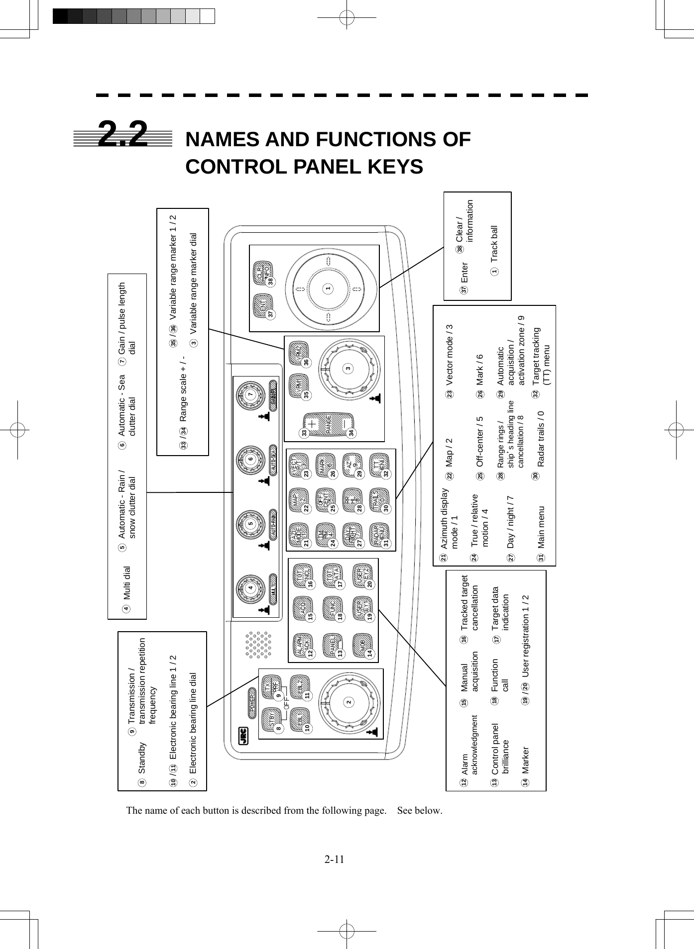
![2-12 2.2 Names and Functions of Control Panel Keysyy2 1 Track ball Use the track ball to move the cursor mark to any position. For example, use it for setting in each mode and specifying a floating EBL center position and off-center position. 2 [EBL] (Electronic Bearing Line) dial Turn the dial to rotate the bearing of the EBL. By pressing the dial, the selected EBL can be switched. (Center fixing) ⇒ C (Floating) ⇒ D (latitude / longitude fixing) ⇒ * D is enabled only when the navigator is connected. 3 [VRM] (Variable Range Marker) dial Turn the dial to change the VRM range. Press the dial to set the display of parallel index line (PI) to On / Off and open the PI Menu. 4 [MULTI] dial Press the dial to switch the function that is registered in the multi-dial. Vecto r ⇒ Trails ⇒ TGT No. ⇒ Course ⇒ Track ⇒ Mark ⇒ Tune ⇒ Vector The function that is switched is displayed in multi-dial mode (lower left of the display on page 2-3) If the dial is pressed for 2 seconds, the Multi Dial Setting menu is opened. If the dial is pressed again for 2 seconds, the setting menu is closed. 5 [AUTO-RAIN] (Automatic - Rain / Snow clutter suppression) dial Turn the dial to suppress images by rain / snow clutter. Turn the dial clockwise to increase the effect of suppression. Press the dial to switch the mode to manual / automatic. 6 [AUTO-SEA] (Automatic - Sea clutter suppression) dial Turn the dial to suppress images by sea clutter. Turn the dial clockwise to increase the effect of suppression. Press the dial to switch the mode to manual / automatic. 7 [GAIN / PL] (Gain / Pulse Length) dial Turn the dial to adjust the reception gain of the radar. Turn the dial clockwise to increase the gain. Press the dial to switch the transmitting pulse length. 8 [STBY] (Standby) key Use this key to turn on the power of the equipment. Use this key also to switch the equipment from a transmitting state to a standby state. The power can be turned off by pressing the [STBY] key and [TX / PRF] key concurrently while the power is On. 9 [TX / PRF] (Transmission / transmission repetition frequency) key At expiration of the pre-heat time after the power is turned on, Preheat of the transmission / standby indication (Upper left of the display on page 2-2) changes to Standby . If this key is pressed subsequently, transmission starts. If this key is pressed during transmission, fine adjustments of the transmission repetition frequency are enabled. By using the fine adjustments of the transmission repetition frequency and the interference removal function, the interference suppression effect can be improved.](https://usermanual.wiki/Japan-Radio/NKE2254.Users-Manual/User-Guide-1510215-Page-75.png)
![2-13 10 / 11 [EBL1] / [EBL2] (Electronic Bearing Line 1 / 2) key Use these keys to switch EBL1 / EBL2 to On / Off. If the key is pressed for 2 seconds, the EBL / Cursor Setting menu is opened. 12 [ALARM ACK] (Alarm acknowledgment) key Use this key to acknowledge the alarm such as a failure alarm and a collision alarm. To stop the alarm, press this key while the alarm sound is emitted. If multiple alarms occur, press this key same time as the alarms. 13 [PANEL] (Control panel brilliance) key Use this key to adjust the brilliance of various keys and dials on the control panel. 14 [MOB] (Marker) key (Not used on the JPL-600-MK2 for VTS) Use this key to store the radar station position at the time. The marker can be cleared by pressing the key for 2 seconds. 15 [ACQ] (Manual acquisition) key Use this key to acquire a target of the cursor position manually. 16 [TGT CNCL] (Tracked target cancellation) key Use this key to cancel the tracked target symbol / vector at the cursor position and stop tracking. When this key is pressed for 2 seconds, all the tracked target symbols / vectors are cancelled and tracking is stopped. 17 [TGT DATA] (Target data indication) key Use this key to check the digital information of the AIS target or the tracked target. 18 [FUNC] (Function call) key Use this key to switch the original signal processing settings. FUNC Off ⇒ Coast ⇒ Deep Sea ⇒ Fishnet ⇒ Storm ⇒ FUNC Off If the key is pressed for 2 seconds, the User Function Setting menu is displayed. 19 / 20 [USER KEY 1 / 2] (User registration 1 / 2) key Use this key to perform pre-registered operations. If this key is pressed for 2 seconds while no operation is registered, the User Key Setting menu is opened. 21 [AZI MODE / 1] (Azimuth display mode / 1) key Switch the azimuth display. H Up (Head Up) ⇒ N Up (North Up) ⇒ C Up (Course Up) ⇒ N Up During the menu operation, the key functions as a numeric key [1]. If this key is pressed for 2 seconds, GYRO setting menu is opened. 22 [MAP / 2] key Use this key to switch the map display to On / Off such as marine chart, coastline, and depth contour. During the menu operation, the key functions as a numeric key [2]. If this key is pressed for 2 seconds, the Map Setting menu is opened.](https://usermanual.wiki/Japan-Radio/NKE2254.Users-Manual/User-Guide-1510215-Page-76.png)
![2-14 2.2 Names and Functions of Control Panel Keysyy2 23 [VECT R / T / 3] (Vector mode / 3) Use this key to switch vector indication T (true vector) / R (relative vector). During the menu operation, the key functions as a numeric key [3]. 24 [TM / RM / 4] (True Motion / Relative Motion / 4) key Display does not change even if this key is switched on the JPL-600-MK2 for VTS. Use this key to switch the motion mode between TM (true motion) and RM (relative motion). If the key is pressed for 2 seconds in TM , the radar station position is reset. During the menu operation, the key functions as a numeric key [4]. 25 [OFF CENT / 5] (Off-center / 5) key By pressing this key, moving the cursor, and pressing the [ENT] key, the ship's position can be moved to the cursor position. The moving range is about 66% of the radius. If the key is pressed for 2 seconds, the off-center is set to Off and the ship's position is returned to the center of the screen. During the menu operation, the key functions as a numeric key [5]. 26 [MARK / 6] (Mark / 6) key Use this key to display a mark in any screen position. This key can also be used for clearing the mark that is currently displayed. If the key is pressed for 2 seconds, the Mark Setting menu is opened. During the menu operation, the key functions as a numeric key [6]. 27 [DAY / NIGHT / 7] (Day / night mode / 7) key Use this key to switch the color and brightness of the screen that have been set in advance. If the key is pressed for 2 seconds, the Display Color Setting menu is opened. During the menu operation, the key functions as a numeric key [7]. 28 [RR / HL / 8] (Range Rings / scanner heading line off / 8) key Use this key to set the range rings marker to On / Off. If the key is pressed for 2 seconds, the scanner heading line is cleared while the key is pressed. During the menu operation, the key functions as a numeric key [8]. 29 [AZ / 9] (Automatic Acquisition / Activation Zone / 9) key Use this key to set automatic acquisition / activation zone. If the key is pressed for 2 seconds, the AZ Menu (automatic acquisition / activation zone menu) is opened. During the menu operation, the key functions as a numeric key [9]. 30 [TRAILS / 0] (Radar trails / 0) key Use this key to switch the length of the radar trail period. If the key is pressed for 2 seconds, the RADAR Trails setting menu is opened. If this key is pressed for 5 seconds, the radar trail is cleared. During the menu operation, the key functions as a numeric key [0]. 31 [RADAR Menu] (Main menu) key Use this key to open the Main Menu. 32 [TT Menu] key Use this key to open the TT Menu (target tracking menu).](https://usermanual.wiki/Japan-Radio/NKE2254.Users-Manual/User-Guide-1510215-Page-77.png)
![2-15 33 / 34 [RANGE + / - ] key Press the [+] key to increase the observation range and the [-] key to reduce the observation range. 35 / 36 [VRM 1 / 2 ] (Variable Range Marker 1 / 2) key Use this key to set the display of VRM1 / VRM2 to On / Off and acquire the operation right. 37 [ENT] (Enter) key Use this key to confirm menu selection and input of numeric values. This key is equivalent to the clicking of the left button of the track ball. 38 [CLR / INFO] (Clear / information) key Use this key to cancel menu selection or numeric value input. This key is equivalent to the clicking of the right button of the track ball.](https://usermanual.wiki/Japan-Radio/NKE2254.Users-Manual/User-Guide-1510215-Page-78.png)
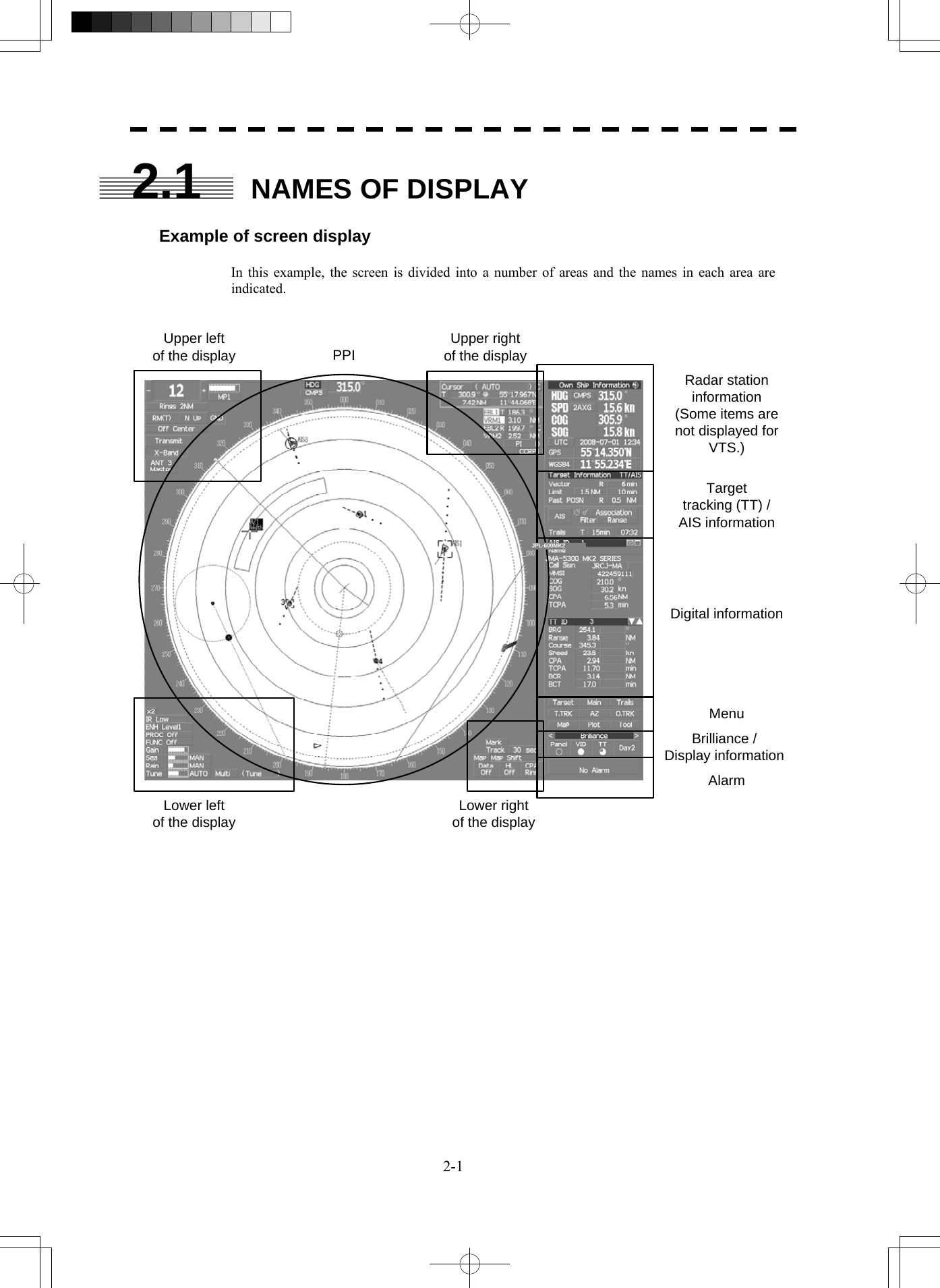
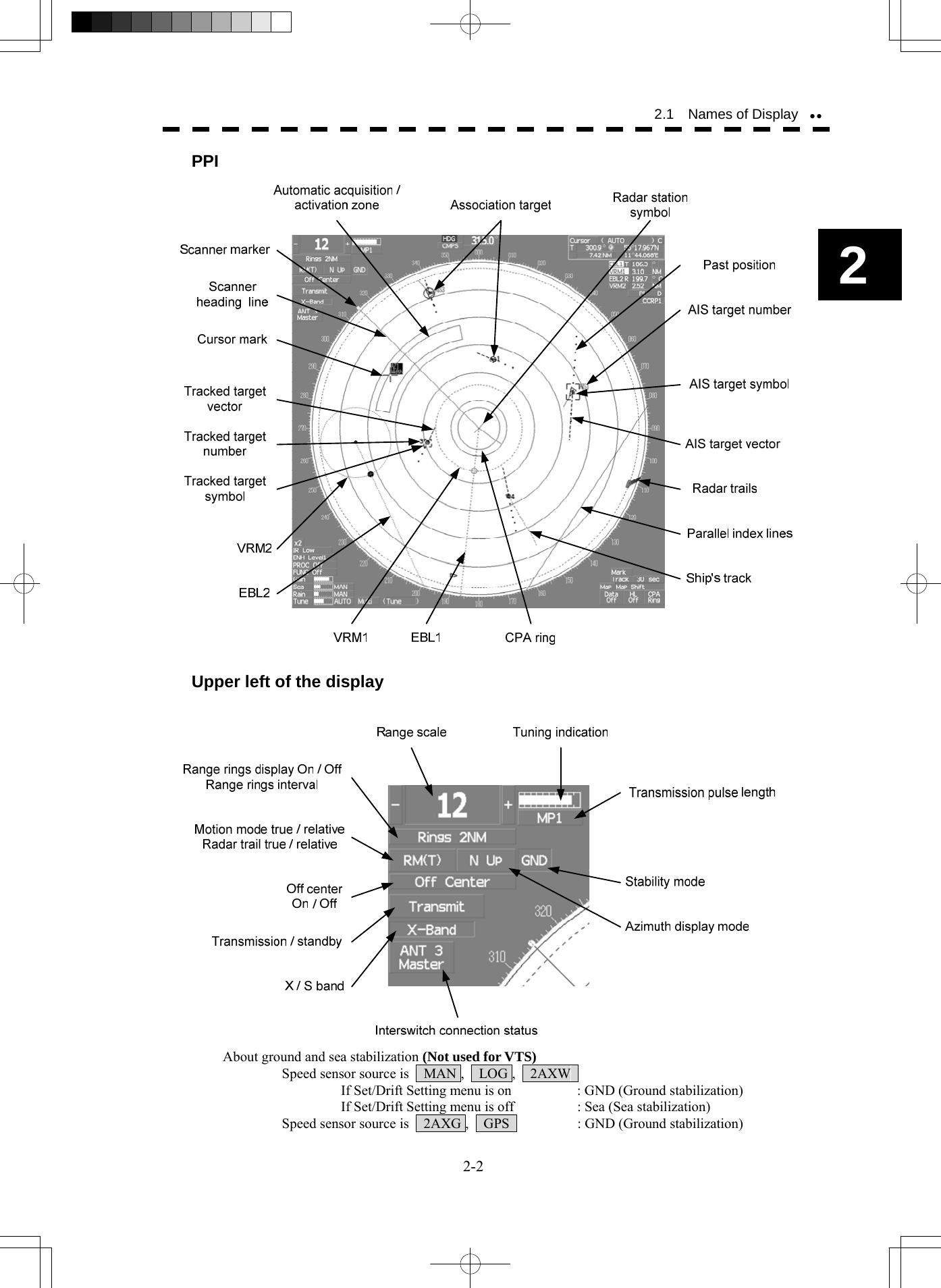
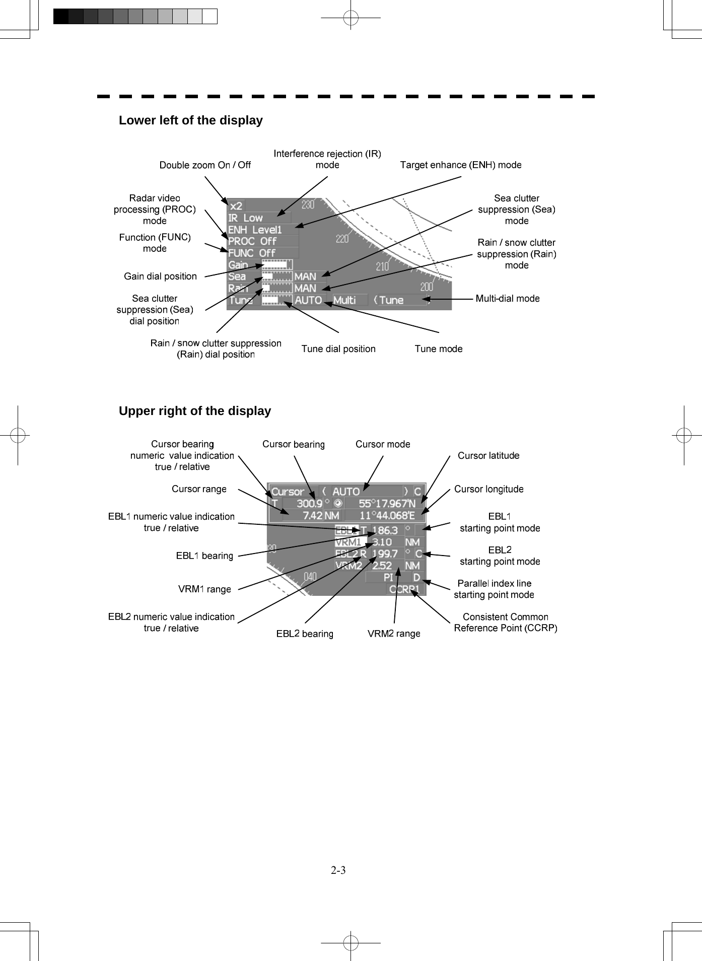
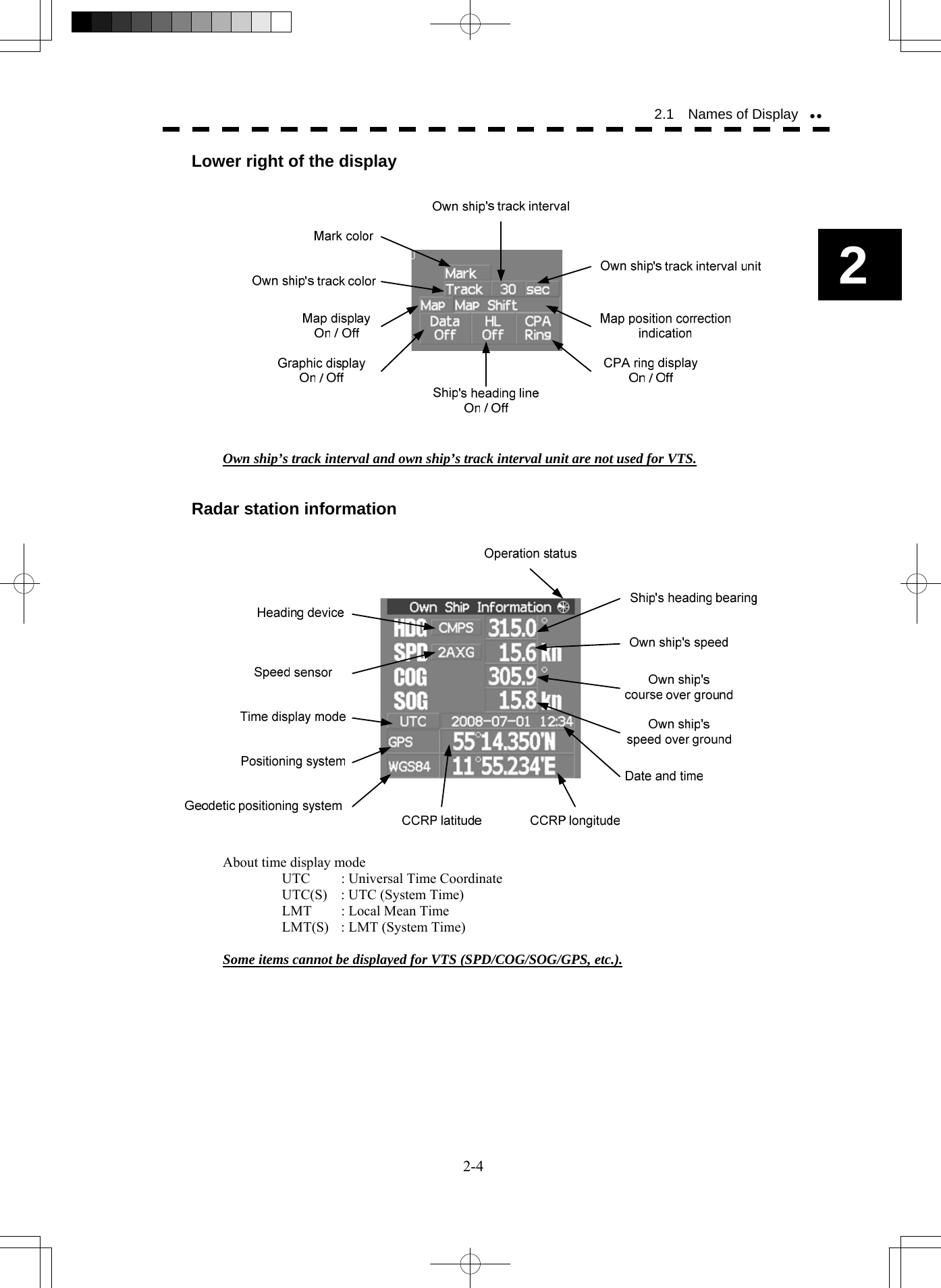
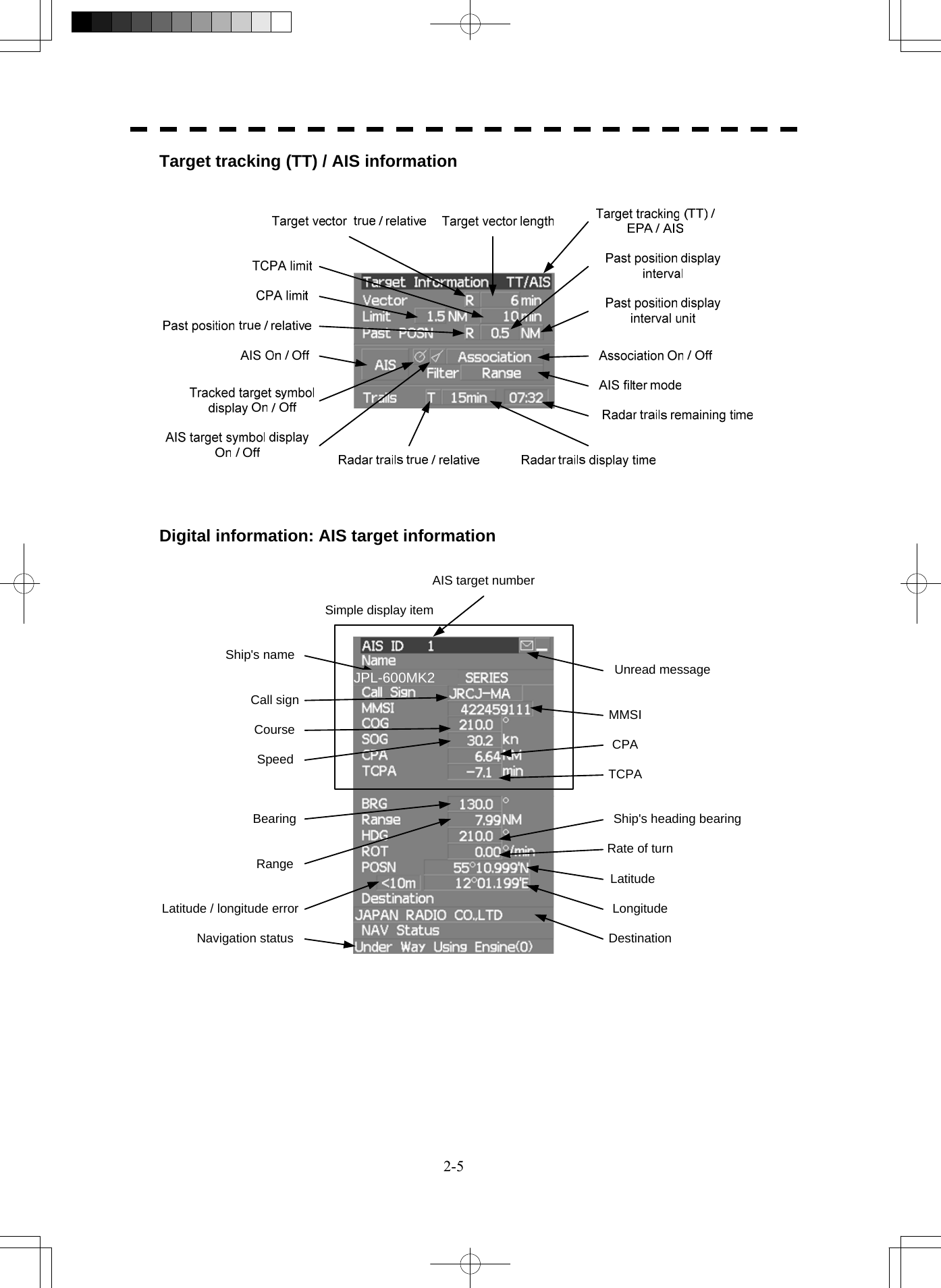
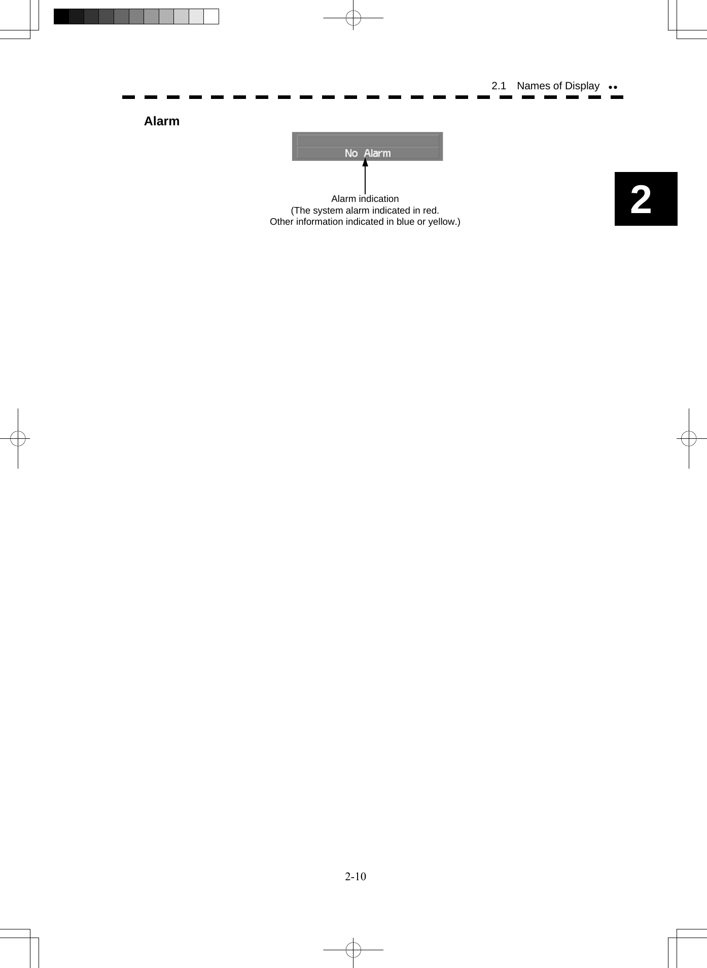
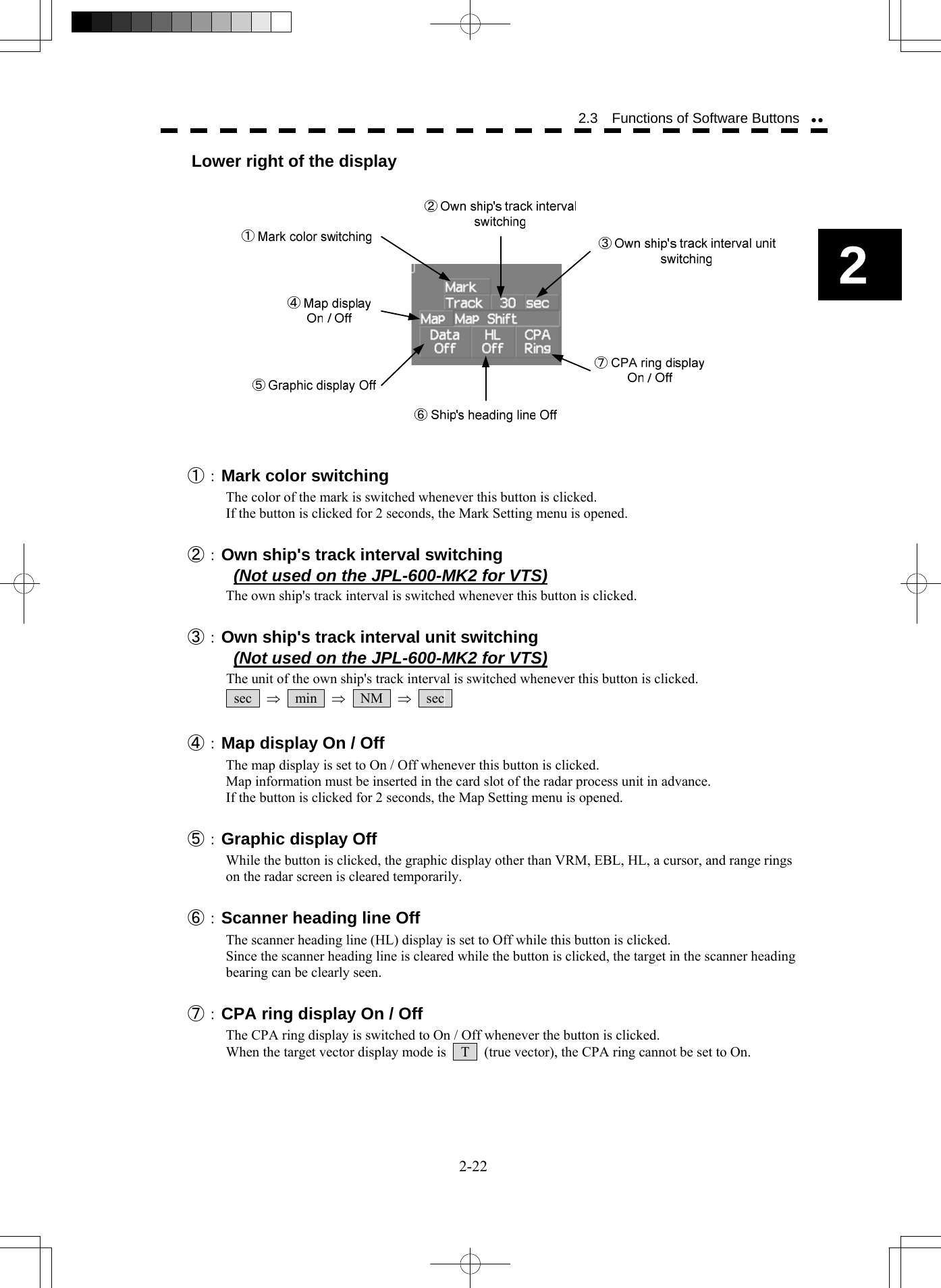
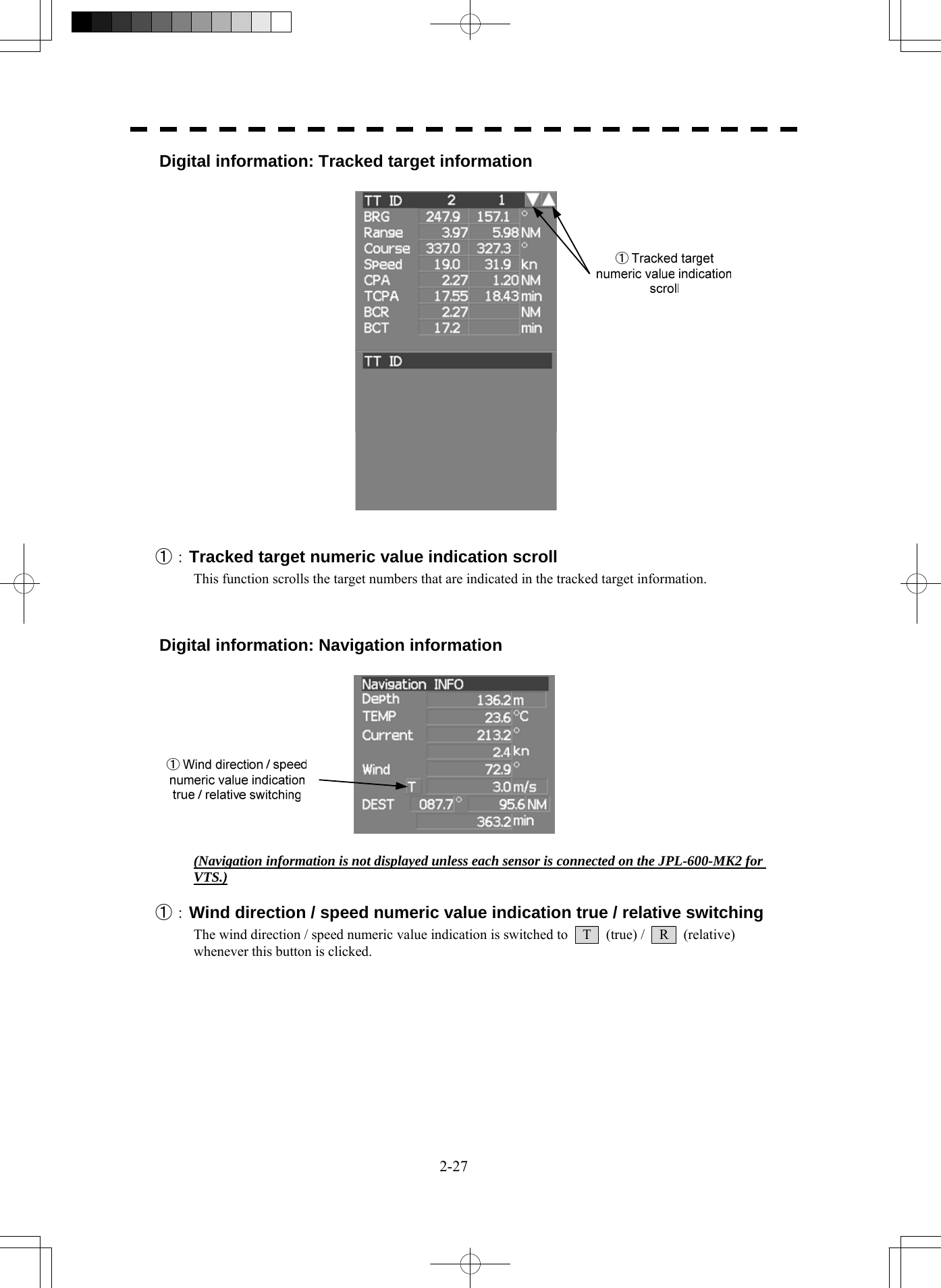
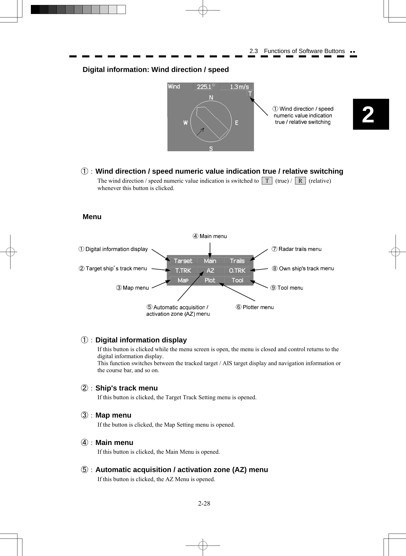
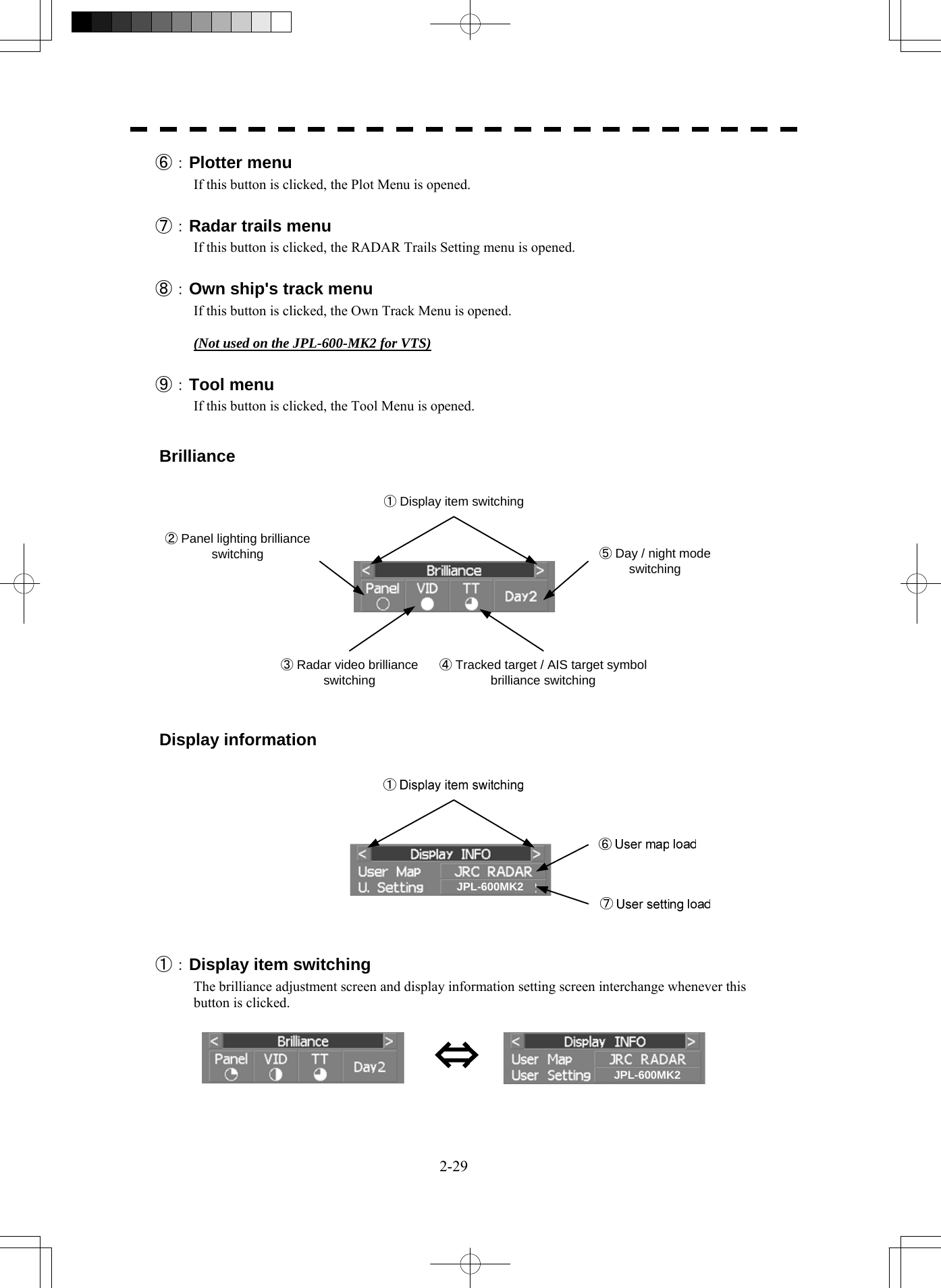
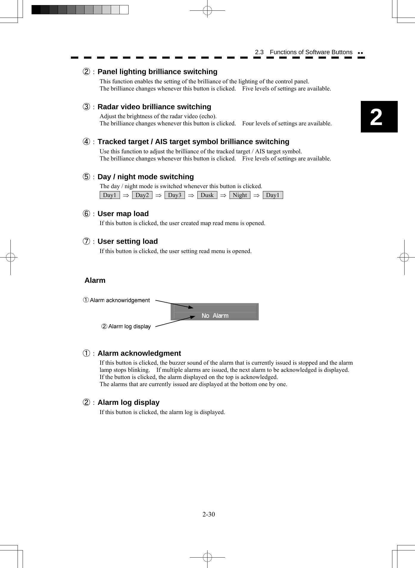
![2-16 2 2.3 Functions of Software Buttons yy2.3 FUNCTIONS OF SOFTWARE BUTTONS In this radar, the frequently used functions can be directly set from the screen without opening the menu by using the software buttons on the screen for quick handling. The screen is divided into a number of areas and each area is named. PPIUpper leftof the displayLower leftof the displayUpper rightof the displayLower rightof the displayRadar station information(Some items are not displayed for VTS.)Digital informationTargettracking (TT) /AIS informationMenuBrilliance /Display informationAlarm The name of each button is described from the next page. The function can be used by pressing (clicking) the [ENT] key while setting the arrow cursor on the button position. JPL-600MK2](https://usermanual.wiki/Japan-Radio/NKE2254.Users-Manual/User-Guide-1510215-Page-79.png)
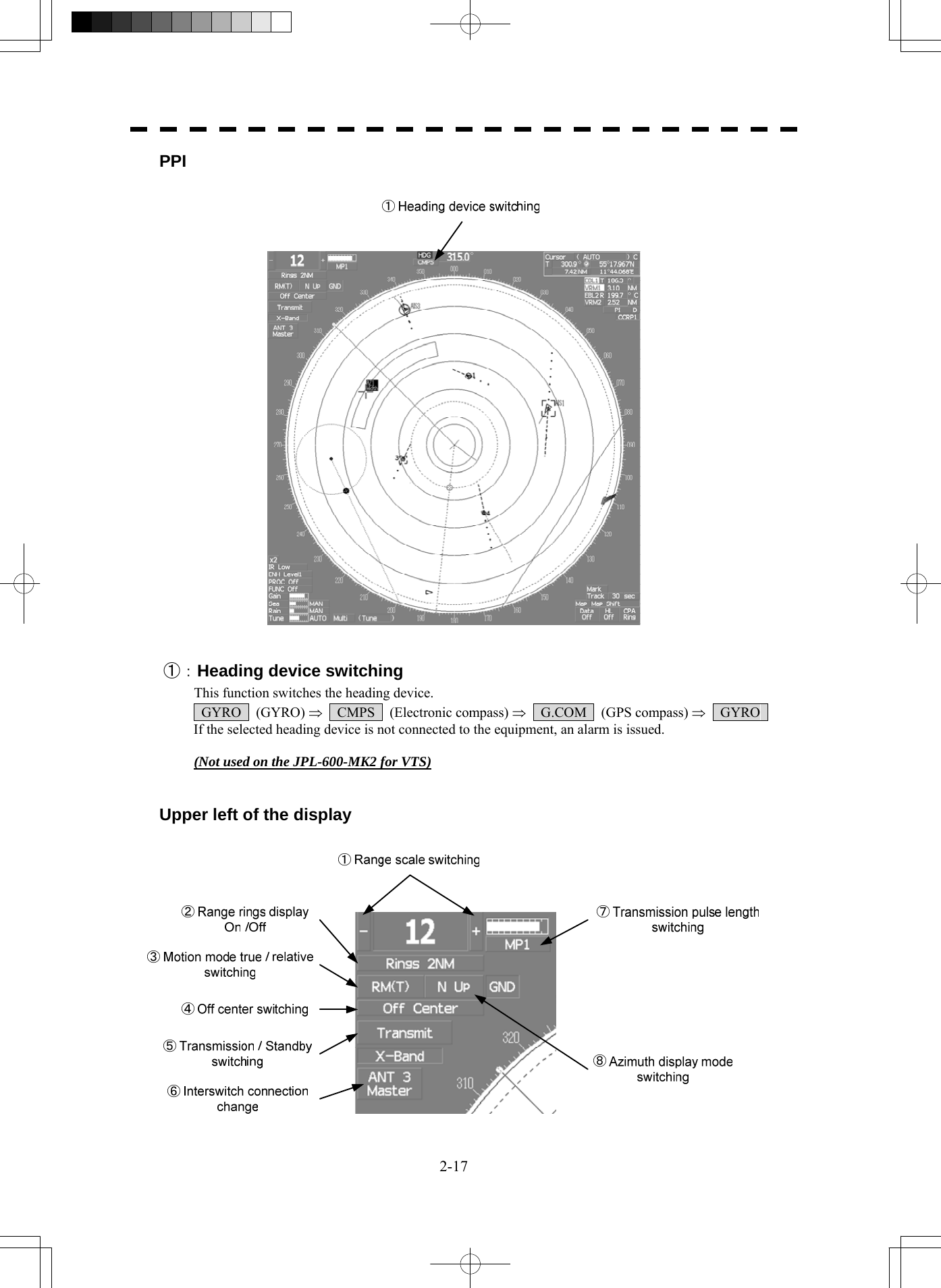
![2-18 2 2.3 Functions of Software Buttons yy①:Range scale switching To increase the observation range scale (maximum 96NM), click + and to reduce the range (minimum 0.125NM), click - . ②:Range rings display On / Off The display of range rings are set to On / Off whenever this button is clicked. When the display is set to On, the interval of the fixed range marker is displayed. ③:Motion mode true / relative switching (Display does not change even if this key is switched to “relative motion” on the JPL-600-MK2 for VTS.) The screen motion mode is switched whenever the button is clicked. TM (true motion) ⇒ RM (relative motion) ⇒ TM RM(R) indicates that the radar trails is a relative trail. RM(T) indicates that the radar trails is a true trail. ④:Off center switching If this button is clicked, the cursor is moved, and the [ENT] key is pressed, the radar station position can be moved to the cursor position. The moving range is within 66% of the radius. If the button is clicked for 2 seconds, the off-center is set to Off and the ship's position is returned to the center of the screen. ⑤:Transmission / standby switching At expiration of the pre-heat time after the power is turned on, Preheat changes to Standby . Standby : Indicates a standby state. If this button is clicked in this state, the equipment is set to a transmission state. Transmit : Indicates a transmission state. If this button is clicked in this state, the equipment is set to a standby state. ⑥:Interswitch connection change This button is displayed when the interswitch is connected. This button indicates the connection status of the scanner unit that is connected to the indicator. If the button is clicked in the transmission standby state, the menu for changing the connection state between the scanner unit and the indicator is displayed. The connection state of the scanner unit and indicator cannot be changed unless the master indicator is in a standby state. → Refer to the Interswitch (Optional) Instruction Manual that is attached for the setting method. This button is not displayed if the interswitch is not connected. ⑦:Transmission pulse length switching The transmission pulse length is switched whenever this button is clicked. Three types of pulses are available, short pulse (SP), middle pulse (MP), and long pulse (LP). The pulse length and repetition frequency vary even for the same short pulse, according to the range that is used and it is displayed as SP1 , SP2 . ⑧:Azimuth display mode switching The azimuth display is switched whenever this button is clicked. H Up (Head Up) ⇒ N Up (North Up) ⇒ C Up (Course Up) ⇒ H Up If the button is clicked for 2 seconds, the GYTO Setting menu is displayed. (Display does not change even if “Course Up” is selected on the JPL-600-MK2 for VTS.)](https://usermanual.wiki/Japan-Radio/NKE2254.Users-Manual/User-Guide-1510215-Page-81.png)
![2-19 Lower left of the display ①:Double zoom switching Use this function to enlarge to double the size the display screen of the position specified by the cursor. If this button is clicked, the zoom mode is set. When the cursor is moved to the radar screen and the [ENT] key is pressed, the screen is enlarged to double the size so that the middle of the cursor and the radar station position is set to the center of the screen. This function cannot be used when the range is 0.125NM. ②:Interference rejection (IR) mode switching The interference rejection mode is switched whenever this button is clicked. IR Off ⇒ IR Low ⇒ IR Medium ⇒ IR High ⇒ IR Off ③:Target enhance (ENH) mode switching The target enhance mode is switched whenever this button is clicked. ENH Off ⇒ ENH Level1 ⇒ ENH Level2 ⇒ ENH Level3 ⇒ ENH Off ④:Radar video processing (PROC) mode switching The radar video processing mode is switched whenever this button is clicked. PROC Off ⇒ 3Scan CORREL ⇒ 4Scan CORREL ⇒ 5Scan CORREL ⇒ ⇒ Remain ⇒ Peak Hold ⇒ PROC Off ⑤:Function (FUNC) mode switching The function mode is switched whenever this button is clicked. FUNC Off ⇒ Coast ⇒ Deep Sea ⇒ Fishnet ⇒ Storm ⇒ FUNC Off If the button is clicked for 2 seconds, the function registration menu (User Function Setting) is opened.](https://usermanual.wiki/Japan-Radio/NKE2254.Users-Manual/User-Guide-1510215-Page-82.png)
![2-20 2 2.3 Functions of Software Buttons yy⑥, ⑦, ⑧,and ⑨:Gain, Sea clutter suppression (Sea), Rain / snow clutter suppression (Rain), Tune adjustment Adjust the gain, sea clutter suppression, rain and snow clutter suppression and tune using the track ball. If the button is clicked on, the adjustment value is shown at the upper-right of the cursor. Make adjustments by moving the track ball to the left and right. Determine the adjustment by pressing the [ENT] key. ⑩, ⑪,and ⑫:Sea clutter suppression (Sea) mode, Rain / snow clutter suppression (Rain) mode, and Tune mode switching Use these functions to switch to the manual or automatic mode of sea clutter suppression, rain / snow clutter suppression and tune. The bar on the left side indicates the position of the dial. The mode is switched to MAN (manual) / AUTO (automatic) whenever the button is clicked. If rain / snow clutter suppression is switched to an automatic mode, sea clutter suppression is switched to an automatic mode also. ⑬:Multi-dial mode switching The function that is registered in the multi-dial is switched whenever the button is clicked. Vector ⇒ Trails ⇒ TGT No. ⇒ Course ⇒ Track ⇒ Mark ⇒ ⇒ Tune ⇒ Vector The switched function is displayed in ( ). If the button is clicked for 2 seconds, the Multi Dial Setting menu is opened. If this button is clicked again for 2 seconds, this setting menu is closed. Upper right of the display ①:Cursor mode switching The mode of the function that uses the cursor is switched whenever this button is pressed. AUTO ⇒ ACQ TT ⇒ ACT AIS ⇒ TGT DATA ⇒ CNCL TT ⇒ ⇒ DEACT AIS ⇒ CNCL Data ⇒ □ (Mark) ⇒ -------- (Line) ⇒ ⇒ Property ⇒ AUTO](https://usermanual.wiki/Japan-Radio/NKE2254.Users-Manual/User-Guide-1510215-Page-83.png)
![2-21 ②:Mark font / line pattern switching This function switches a mark font / line pattern. If this button is clicked while the cursor mode is □ (mark) or -------- (line), the mark font / line pattern is changed. ③:Mark color / line color switching This function switches a mark color / line color. If this button is clicked while the cursor mode is □ (mark) or -------- (line), the mark color / line color is changed. ④:Cursor bearing numeric value display true / relative switching The bearing numeric value display T (true bearing) / R (relative bearing) of the cursor is switched whenever this button is clicked. (Display does not change even if “relative bearing” is selected on the JPL-600-MK2 for VTS.) ⑤, ⑥, ⑦,and ⑧:EBL1 / 2 and VRM1 / 2 adjustment These functions set the EBL1 , VRM1 , EBL2 , and VRM2 displays to On / Off and acquire the operation right. If the button is clicked on, the operation right is acquired. Make adjustments by moving the track ball to the left and right Determine the adjustment by pressing the [ENT] key. ⑨ and ⑩:EBL1, EBL2 numeric value true / relative switching The EBL1 / 2 bearing numeric value display T (true bearing) / R (relative bearing) is switched whenever the button is clicked. If the button is clicked for 2 seconds, the EBL / Cursor Setting menu is displayed. ⑪ and ⑫:EBL1 / EBL2 starting point mode switching The EBL starting point is set to the radar station position or any position on the radar screen whenever this button is clicked. ⇒ C ⇒ D ⇒ : Center :The starting point is fixed to the CCRP position. C : Screen Fix :The starting point is set to the cursor position. If the [ENT] key is pressed subsequently, the starting position is fixed to the cursor position. D : L/L Fix :The starting point is set to the cursor position. If [ENT] key is pressed subsequently, the starting position is fixed to the latitude / longitude of the cursor. (Connection of a navigator is necessary.) If the starting point is moved outside of the screen, the operation is reset automatically and the starting point returns to the radar station position. * D is enabled only when a navigator is connected. ⑬:Parallel index line setting This function sets the parallel index line display to On / Off and acquires the operation right. If this button is clicked, the operation right is acquired and the menu is opened. After setting, determine the setting by pressing the [ENT] key. ⑭:Parallel index line starting point mode switching The parallel index line starting point is set to CCRP or any position on the radar screen whenever this button is clicked. In the same way as for the EBL starting point, three options are available, : Center, C : Screen Fix, and D : L/L Fix.](https://usermanual.wiki/Japan-Radio/NKE2254.Users-Manual/User-Guide-1510215-Page-84.png)
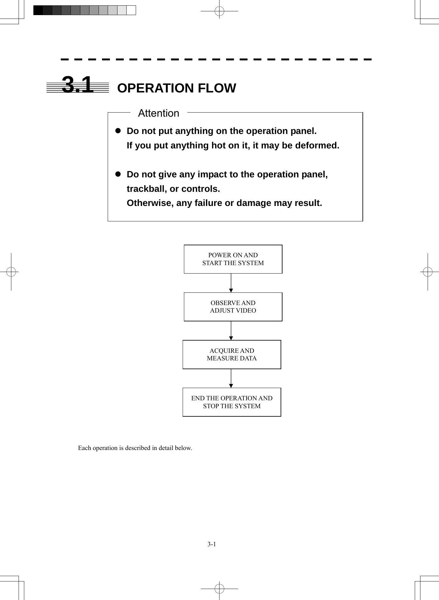
![SECTION 3 BASIC OPERATION 3.1 OPERATION FLOW .......................................................................... 3-1 3.2 OBSERVE AND ADJUST VIDEO ..................................................... 3-5 3.3 OPERATION PROCEDURES ..........................................................3-11 3.4 GENERAL RADAR OPERATION ................................................... 3-21 3.5 USE OWN SHIP'S TRACK DATA ................................................... 3-49 3.6 DISPLAY USER MAP...................................................................... 3-54 3.7 USE ROUTE FUNCTION ................................................................ 3-78 3.8 APPLIED OPERATIONS................................................................. 3-79 3.9 USE FUNCTION KEY [FUNC] ........................................................ 3-94 3.10 USE USER SETTING.................................................................... 3-100 3.11 USING CARD ................................................................................ 3-102 3.12 DISPLAY SIMPLE CHART ........................................................... 3-108](https://usermanual.wiki/Japan-Radio/NKE2254.Users-Manual/User-Guide-1510215-Page-94.png)
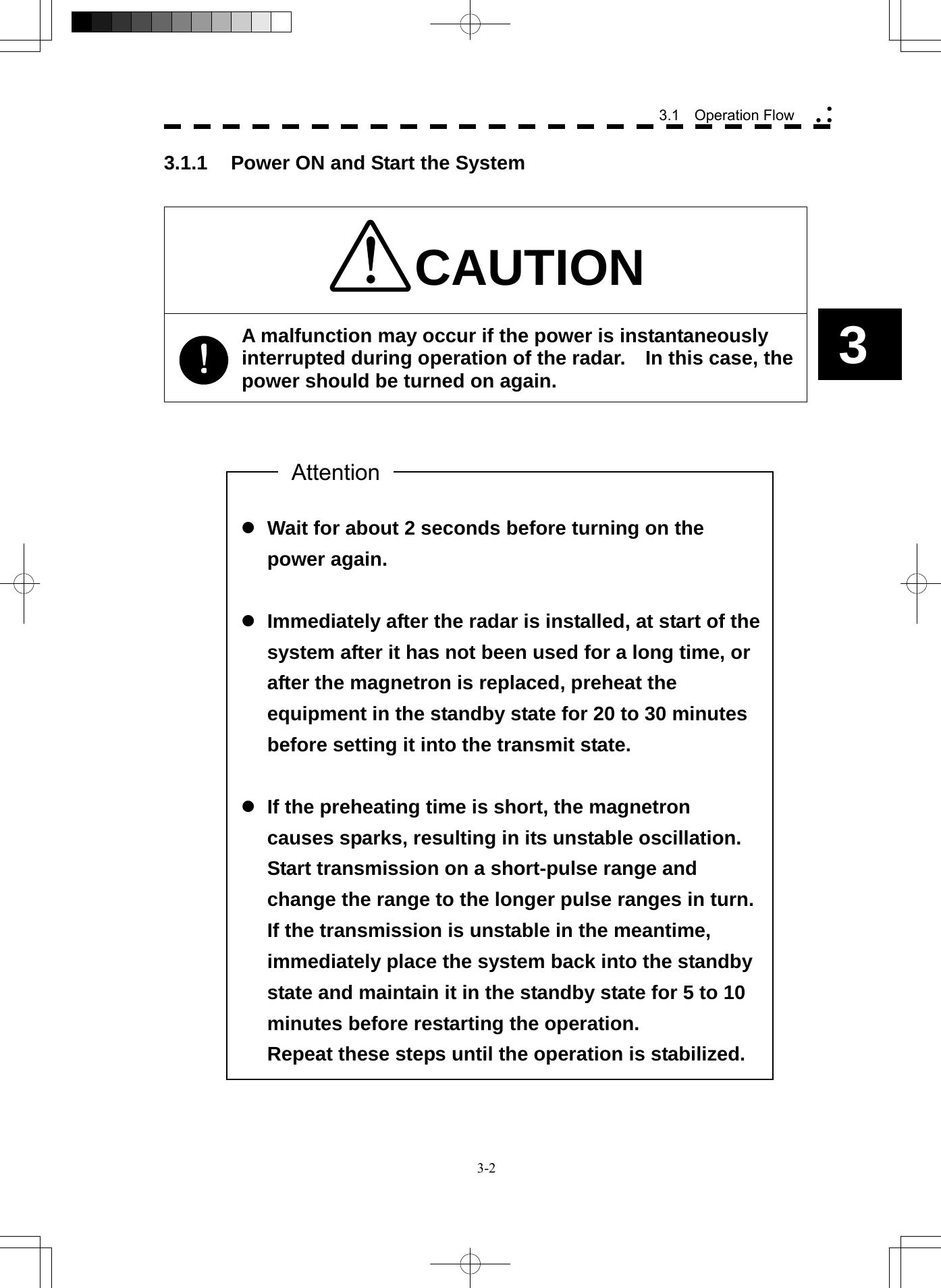
![3-3 Procedures 1 Be sure that the commercial power is being supplied. 2 Press the [STBY] key. The system is turned on, and the preheating time is displayed. Preheat is indicated upper left of the display. 3 Wait until the preheating time is over. When the preheating time is over, the preheating time screen disappears, and Preheat upper left of the display changes to Standby . 4 Press the [TX / PRF] key. The radar will start transmission and the antenna will start rotating. Standby upper left of the display changes to Transmit . Note: The radar does not start transmission if you Press the [TX / PRF] key while Preheat is indicated. 3.1.2 Observe and Adjust Video Procedures 1 Press the [RANGE+] key or [RANGE-] key to set the range to the scale required for target observation. 2 Turn the dials [GAIN / PL], [AUTO-SEA], and [AUTO-RAIN] to obtain the clearest targets. Refer to [GAIN/PL]→3-7P [AUTO-SEA]→3-7P [AUTO-RAIN]→3-9P for how to use each dial. For how to adjust video, see Chapter 3.2. 3.1.3 Acquire and Measure Data For details on how to acquire data and measure, see Section 4 "Measurement of range and bearing." 3.1.4 Display and Measure with Reference to CCRP The radar video, range, bearing, Target Tracking and AIS data display etc... are displayed with reference to CCRP (Consistent Common Reference Point). If scanner is switched, these data are measured from CCRP. If some kind of functions set scanner position to outside of the PPI range, these data except Target Tracking and AIS data are displayed with reference to scanner position. For how to setting CCRP, see the section 7.1.9.](https://usermanual.wiki/Japan-Radio/NKE2254.Users-Manual/User-Guide-1510215-Page-98.png)
![3-4 3.1 Operation Flow yy y3 3.1.5 End the Operation and Stop the System Exit 1 Press the [STBY] key. The radar will stop transmission and the antenna will stop rotating. Transmit upper left of the display changes to Standby . Maintain the standby state if radar observation is restarted in a relatively short time. Only pressing the [TX / PRF] key starts observation. 2 Press the [STBY] key and the [TX / PRF] key together. The system will be turned off.](https://usermanual.wiki/Japan-Radio/NKE2254.Users-Manual/User-Guide-1510215-Page-99.png)
![3-5 3.2 OBSERVE AND ADJUST VIDEO 3.2.1 Adjust Monitor Brilliance [BRILL] Procedures 1 Obtain the best-to-see display with optimum brilliance by turning the [BRILL] dial at the lower right of the LCD monitor. Turning the [BRILL] dial clockwise increases the brilliance of the entire display. Conversely, turning the [BRILL] dial counterclockwise decreases the brilliance of the entire display. In consideration of the ambient brightness, adjust display brilliance that is high enough to easily observe the radar display but does not glare. 3.2.2 Change Observation Range [RANGE + / - ] Procedures 1 When increasing the observation range, press the [RANGE+] key. Increasing the observation range will enable a wider range to be observed. However, a video image is small and the ability to detect targets near own ship decreases. Therefore, when observing the vicinity of own ship, use the smaller observation range. 2 When decreasing the observation range, press the [RANGE-] key. Decreasing the observation range will enable the vicinity of own ship to be enlarged. However, caution must be taken because video images of the area beyond the observation range cannot be displayed.](https://usermanual.wiki/Japan-Radio/NKE2254.Users-Manual/User-Guide-1510215-Page-100.png)
![3-6 3.2 Observe and Adjust Video yy y3 3.2.3 Tune CAUTION Normally, use the automatic tune mode. Use the manual tune mode only when best tuning is not possible in the automatic tune mode due to deterioration of magnetron. This radar system provides the automatic tune mode and the manual tune mode. The automatic tune mode automatically adjusts the tuning of the transmitting frequency and the receiving frequency, and the manual tune mode enables tuning to be adjusted by using the dial located on the operation unit. The tune mode currently being used is displayed in the tune mode switching (lower left of the display ⑫ on page 2-18). When using the automatic tune mode Procedures 1 Put the cursor on the tune mode switching (lower left of the display ⑫ on page 2-18) and press the [ENT] key. The automatic tune mode is selected and AUTO is displayed in the tune mode field. Tune adjustment is automatically conducted. Tune is adjusted at the start of transmission, at the change of the range or pulse length. Tune adjustment is completed within several seconds. When using the manual tune mode Procedures 1 Put the cursor on the tune mode switching (lower left of the display ⑫ on page 2-18) and press the [ENT] key to set the manual tune mode. The automatic tune mode is cancelled, and MAN is displayed in the tune mode field. 2 Press the [MULTI] dial to set the ( Tune ) mode. Tune is displayed in the multi-dial mode (lower left of the display on page 2-3). 3 Turn the [MULTI] dial to adjust tune. Make adjustments so that the tuning indication (upper left of the display on page 2-2) indicates the maximum.](https://usermanual.wiki/Japan-Radio/NKE2254.Users-Manual/User-Guide-1510215-Page-101.png)
![3-7 3.2.4 Adjust Gain [GAIN / PL] CAUTION If the gain is too high, unnecessary signals including receiver noise and false video increase resulting in reduction of visibility of targets. On the contrary, if the gain is too low, targets including ships and dangerous objects may not be clearly indicated. Procedures 1 Adjust noise of the display by turning the [GAIN / PL] dial until targets can be easily observed. Turning [GAIN / PL] dial clockwise increases gain. Turning [GAIN / PL] dial counterclockwise decreases gain. By increasing receiving gain, the range to observe radar video is widened. To observe densely crowded targets or short-range targets, reducing the receiving gain will enable the targets to be easily observed. 3.2.5 Suppress Sea Clutter [AUTO-SEA] CAUTION When using the sea clutter suppression function, never set the suppression level too high canceling out all image noises from the sea surface at close range. Detection of not only echoes from waves but also targets such as other ships or dangerous objects will become inhibited. When using the sea clutter suppression function, make sure to choose the most appropriate image noise suppression level.](https://usermanual.wiki/Japan-Radio/NKE2254.Users-Manual/User-Guide-1510215-Page-102.png)
![3-8 3.2 Observe and Adjust Video yy y3 Using the manual sea clutter suppression mode Procedures 1 Adjust the sea clutter returns of the display by turning the [AUTO-SEA] dial until targets can be easily observed. Turning [AUTO-SEA] dial clockwise suppresses sea clutter returns. Turning [AUTO-SEA] dial counterclockwise intensifies sea clutter returns. The sea clutter suppression function suppresses sea clutter returns by decreasing the receiving gain on a short range. Turning the [AUTO-SEA] dial clockwise heightens the effect of sea clutter suppression. However, be careful that excessive suppression causes low signal-strength targets such as buoys and boats to disappear from the radar display. Using the automatic sea clutter suppression mode The sea clutter suppression in accordance with the intensity of sea clutter is possible. Use this mode when the sea clutter's intensity differs according to directional orientation. Procedures 1 Press the [AUTO-SEA] dial. The automatic sea clutter suppression mode is selected, and AUTO is displayed in sea clutter suppression (Sea) mode switching (lower left of the display ⑩ on page 2-18). 2 Make adjustments by turning the [AUTO-SEA] dial. Even when the automatic sea clutter suppression mode is selected, turning the [AUTO-SEA] dial can make fine adjustments manually. Note: When the automatic sea clutter suppression mode is selected, the automatic rain/snow clutter suppression mode is switched to the manual mode. To select both the sea clutter suppression function and the rain/snow clutter suppression function in the automatic mode, use the automatic rain/snow clutter suppression mode. Cancellation 1 Press the [AUTO-SEA] dial. The automatic sea clutter suppression mode is cancelled, and MAN is displayed in the sea clutter suppression (Sea) mode field.](https://usermanual.wiki/Japan-Radio/NKE2254.Users-Manual/User-Guide-1510215-Page-103.png)
![3-9 3.2.6 Suppress Rain / Snow Clutter [AUTO-RAIN] CAUTION When using the rain / snow clutter suppression function, never set the suppression level too high canceling out all image noises from the rain or snow at the close range. Detection of not only echoes from the rain or snow but also targets such as other ships or dangerous objects will become inhibited. When using the rain / snow clutter suppression function, make sure to choose the most appropriate image noise suppression level. Using the manual rain / snow clutter suppression mode Procedures 1 Adjust the rain / snow clutter returns of the display by turning the [AUTO-RAIN] dial until targets can be easily observed. Turning [AUTO-RAIN] dial clockwise suppresses rain / snow clutter returns. Turning [AUTO-RAIN] dial counterclockwise intensifies rain / snow clutter returns. When the [AUTO-RAIN] dial is turned clockwise, the rain / snow clutter suppression function suppresses rain / snow clutter returns and gets targets hidden by rain / snow clutter returns to appear of the display. However, be careful that excessive suppression may cause small targets to be overlooked. Since the rain / snow clutter suppression function also has the effect of suppressing sea clutter, the suppression efficiency improves when the [AUTO-RAIN] dial is used with the [AUTO-SEA] dial. In general, turn the [AUTO-RAIN] dial fully to the left.](https://usermanual.wiki/Japan-Radio/NKE2254.Users-Manual/User-Guide-1510215-Page-104.png)
![3-10 3.2 Observe and Adjust Video yy y3 Using the automatic rain / snow clutter suppression mode The rain / snow clutter suppression in accordance with the intensity of rain / snow clutter is possible. Use this mode when the rain / snow clutter's intensity differs according to directional orientation. Procedures 1 Press the [AUTO-RAIN] dial. The automatic rain / snow clutter suppression mode is selected, and AUTO is displayed in the sea clutter suppression (Sea) mode switching and the rain / snow clutter suppression (Rain) mode switching ( lower left on the display ⑩ and ⑪ on page 2-18) 2 Make adjustments by turning the [AUTO-RAIN] dial and the [AUTO-SEA] dial. Even when the automatic rain / snow clutter suppression mode is selected, turning the [AUTO-RAIN] dial and the [AUTO-SEA] dial can make fine adjustments manually. Note: When the automatic rain / snow clutter suppression mode is selected, the automatic sea clutter suppression mode is also activated. It is not possible to set only the rain / snow clutter suppression function to the automatic mode. Cancellation 1 Press the [RAIN] dial. The automatic rain / snow clutter suppression mode is cancelled, and AUTO is changed to MAN in the sea clutter suppression (Sea) mode field and the rain / snow clutter suppression (Rain) mode field. 3.2.7 Reset Alarm Buzzer [ALARM ACK] When an audible alarm is issued, use [ALARM ACK] to acknowledge the alarm information, stop the alarm buzzing, and stop the alarm lamp flashing. (If more than one alarm has occurred, press the key for each alarm indication.) The alarm stops buzzing, but the alarm indication does not disappear. Procedures 1 Press the [ALARM ACK] key. The alarm will stop buzzing.](https://usermanual.wiki/Japan-Radio/NKE2254.Users-Manual/User-Guide-1510215-Page-105.png)
![3-12 3.3 Operation Procedures yy y3 3.3.2 Operate Software Buttons Software buttons are provided of the display so as to easily switch functions without operating menu items. For software buttons that can be operated and their locations, see Chapter 2. Procedures 1 Put the pointer on the software button of the display. The software button indicated by the cursor will be shown in reverse video, which indicates that the button is specified. 2 Press the [ENT] key. The operating state changes according to the function of the software button. On / off settings Each time the [ENT] key is pressed, the operating state switches as follows: On ⇒ Off ⇒ On ⇒ Off Multiple settings For example, each time the [ENT] key is pressed, the operating state switches as follows: IR Off ⇒ IR Low ⇒ IR Middle ⇒ IR High ⇒ IR Off](https://usermanual.wiki/Japan-Radio/NKE2254.Users-Manual/User-Guide-1510215-Page-107.png)
![3-13 3.3.3 Basic Menu Operation To open the menu: Put the cursor on main menu Main (Menu ④ on page 2-27) and press the [ENT] key, and the main menu will open. Alternatively, press the [RADAR MENU] key. By putting the cursor on Target , Map , or AZ adjacent to Main and pressing the [ENT] key, the menu exclusive for the function will open. For the arrangement of software buttons, see Chapter 2. To close the menu: Put the cursor on digital information display Target (Menu ① on page 2-27) and press the [ENT] key, and the menu will close and the digital information display screen will appear. Alternatively, press the [0] key until the menu will close. To move to a lower level of the menu: The menu is in hierarchical structure. Put the cursor on the desired menu item and press the [ENT] key, and control will move to the lower level. Alternatively, Press numeric keys corresponding to the desired menu item number, and the > mark will appear at the right end of a menu item having a lower level. To move to a higher level of the menu: Put the cursor on 0. Exit located lower of the menu when the menu is open. Control will return to the higher level. Alternatively, press the [0] key. To determine an item: Put the cursor on the menu item you want to change and press the [ENT] key. The selected item will be displayed. Alternatively, Press numeric keys corresponding to the desired item number. To determine the selected item: Put the cursor on the desired item and then press the [ENT] key. The selected item will be determined. Alternatively, Press numeric keys corresponding to the selected item number. If you do not change the setting of the selected item, press the [CLR / INFO] key. The selected item will be closed without changing the settings.](https://usermanual.wiki/Japan-Radio/NKE2254.Users-Manual/User-Guide-1510215-Page-108.png)
![3-14 3.3 Operation Procedures yy y3 Example of menu display Press numeric keys corresponding to the desired item number to display the selected item.Press numeric keys corresponding to the desired item number to select a set value.Software buttonPress the [0] key to move to the higher level.When the [ > ] mark appears at the right end of a menu item, press numeric keys corresponding to the selected item number to move to a lower level.ItemSelected itemCursorPresent state](https://usermanual.wiki/Japan-Radio/NKE2254.Users-Manual/User-Guide-1510215-Page-109.png)
![3-15 3.3.4 Operation on Numeric Value, Latitude / Longitude and Character Input menu When a numeric value, latitude / longitude, or character must be entered during operation, the input screen will appear. Enter a numeric value, latitude / longitude, or character according to the procedures below. Numeric value input menu Entered value+ buttonEnter buttonClear button-buttonNumeric button Directly entering a numeric value Procedures 1 On the numeric value input menu, sequentially press numeric keys to enter a desired numeric value. For example, when entering 123.4 ° for a bearing value, sequentially press the keys as follows: [1] → [2] → [3] → [4] 2 Make sure that the entered value is correct, put the cursor on ENT , and then press the [ENT] key. The set value is reflected to the operating state. 3 To cancel input, put the cursor on CLR , and then press the [ENT] key. The numeric value input menu will close without reflecting the set value to the operating state.](https://usermanual.wiki/Japan-Radio/NKE2254.Users-Manual/User-Guide-1510215-Page-110.png)
![3-16 3.3 Operation Procedures yy y3 Increasing or decreasing a numeric value Procedures 1 On the numeric value input menu, put the cursor on + or - , and then press the [ENT] key to increase or decrease numeric value so as to change to the desired numeric value. For example, to change bearing value of 123.0 ° to 123.4 °, put the cursor sequentially on + located on the software numeric value input menu, and then press the [ENT] key four times. * Turning the [MULTI] dial will conduct the same operation. 2 Make sure that the entered value is correct, put the cursor on ENT , and then press the [ENT] key. The set value is reflected to the operating state. 3 To cancel input, put the cursor on CLR , and then press the [ENT] key. The numeric value input menu will close without reflecting the set value to the operating state.](https://usermanual.wiki/Japan-Radio/NKE2254.Users-Manual/User-Guide-1510215-Page-111.png)
![3-17 Latitude / longitude input screen Entered latitude/longitude+ button (north latitude/east longitude)ENT buttonCLR button- button (south latitude/west longitude)Numeric button Entering latitude / longitude Procedures 1 On the latitude / longitude input menu, sequentially press numeric keys to enter latitude (XX°XX.XXX'). For example, to enter 12°34.567'N, sequentially press numeric keys as follows. [1] → [2] → [3] → [4] → [5] → [6] → [7] 2 To make change between north latitude and south latitude, use + and - . North latitude: Put the cursor on + and then press the [ENT] key. South latitude: Put the cursor on - and then press the [ENT] key. 3 Put the cursor on ENT and then press the [ENT] key. The manually entered latitude value is determined. Then, enter the longitude value. 4 Sequentially press numeric keys to enter longitude (XXX°XX.XXX'). 5 To make change between east longitude and west longitude, use + and - . East longitude: Put the cursor on + and then press the [ENT] key. West longitude: Put the cursor on - and then press the [ENT] key. 6 Put the cursor on ENT and then press the [ENT] key. The manually entered longitude value is determined.](https://usermanual.wiki/Japan-Radio/NKE2254.Users-Manual/User-Guide-1510215-Page-112.png)
![3-18 3.3 Operation Procedures yy y3 7 To cancel input, put the cursor on CLR and then press the [ENT] key. The latitude / longitude input menu will close without reflecting the set value to the operating state. Character input screen Entering a character Procedures 1 On the character input menu, use trackball to select alphabet from A to Z, numbers from 0 to 9, or symbols (only comments for mark / line), and then press the [ENT] key to enter one character of the name to be inputted. For example, JRC for a name, click button as follows: J → R → C 2 Make sure that the entered character is correct, put the cursor on ENT , and then press the [ENT] key. The character has been entered. 3 To cancel input, put the cursor on Exit , and press the [ENT] key. The character input menu will be closed without entering the character.](https://usermanual.wiki/Japan-Radio/NKE2254.Users-Manual/User-Guide-1510215-Page-113.png)
![3-19 3.3.5 Overview of Menu Structure The menu structure of this radar system consists of seven frequently used function menus, one main menu, and one service man menu used for the installation settings. Software buttons for opening those menus are displayed in the menu area. For each menu item and structure, see the menu list in the appendix. To prevent incorrect use, enter the special code to open the service man menu. For operating the service man menu, see Chapter 7. Frequently used functions Trails Used for operating and setting the radar trails function. T.TRK Used for operating and setting the target track function. AZ Used for operating and setting the automatic acquisition / activation function. O.TRK Used for operating and setting the own ship track function. (Not used on the JPL-600-MK2 for VTS) Map Used for operating and setting the map function. Plot Used for operating and setting the plotter function. Tool Used for operating and setting the navigation tool functions. Main menu Main Used for operating and setting the functions other than the above. Service man menu This menu is used for operation and settings when a system is installed. It is not used during normal operation. The special code must be entered to open the service man menu. 3.3.6 Operate Multi-Dial [MULTI] The [MULTI] dial is provided to change the settings of parameters such as the length of radar trails. Radar operation is simplified by using the [MULTI] dial. [I] Initial Setting (Multi Dial Setting) Set parameters that can be operated with the multi-dial. Procedures 1 Press the [MULTI] dial for 2 seconds. The Multi Dial Setting menu will appear.](https://usermanual.wiki/Japan-Radio/NKE2254.Users-Manual/User-Guide-1510215-Page-114.png)
![3-20 3.3 Operation Procedures yy y3 2 Press numeric keys corresponding to the desired item number. On and off functions of the item are switched. On : Operation is conducted by the [MULTI] dial. Off : Operation is not conducted by the [MULTI] dial. Items set to On can be opened by pressing the [MULTI] dial. Item overview Vector Length : The vector length of tracked target and activate AIS target is adjusted. Trails Length : The radar trails length is adjusted. TT Display No. : The target numbers of tracked target to be displayed are switched. C-Up Angle : The course in the course up mode is adjusted. Mark/Line Color : Mark / line colors are switched. Manual Tune : Tune in the manual tune mode is adjusted. [II] Using Multi-dial Procedures 1 Press the [MULTI] dial to select the parameter whose setting is to be changed. The multi-dial modes are switched. Vector ⇒ Trails ⇒ TGT No. ⇒ Course ⇒ Mark ⇒ ⇒ Tune ⇒ Vector The selected item is displayed in the multi-dial mode (lower left of the display on page 2-3). For example, when three items, 1/2/3, are set to On at the initial setting, the multi-dial modes switch as shown below every time the [MULTI] dial is pressed. Vector ⇒ Trails ⇒ TGT No. ⇒ Vector 2 Turn the [MULTI] dial to change the setting. The preset values of the selected parameter will change sequentially. Stop turning the dial when the desired value appears.](https://usermanual.wiki/Japan-Radio/NKE2254.Users-Manual/User-Guide-1510215-Page-115.png)
![3-21 3.4 GENERAL RADAR OPERATION 3.4.1 Interference Rejection (IR) Interference by other radars is rejected. Procedures 1 Put the cursor on interference rejection (IR) mode switching IR ( ② lower left of the display on page 2-18) and press the [ENT] key. The interference rejection modes are switched. IR Off ⇒ IR Low ⇒ IR Middle ⇒ IR High ⇒ IR Off Rejection levels of the interference rejection IR Off : Interference rejection off IR Low : Interference rejection level - low IR Middle : Interference rejection level - middle IR High : Interference rejection level - high When a high interference rejection level is selected, the radar’s ability of detecting small targets such as buoys and small boats lowers. In general, IR Low should be selected. z When viewing a radar beacon or SART signal, select IR Off (Interference Rejection Off) because IR processing suppresses the video. Attention](https://usermanual.wiki/Japan-Radio/NKE2254.Users-Manual/User-Guide-1510215-Page-116.png)
![3-22 3.4 General Radar Operation yy y3 3.4.2 Switch Transmitter Pulse Length [GAIN / PL] Procedures 1 Press the [GAIN / PL] dial. Values of the transmitter pulse length are switched. Example MP1 ⇒ MP2 ⇒ LP1 ⇒ LP2 ⇒ MP1 Effects of transmitter pulse length With SP selected: The transmitter pulse becomes shorter, and the range resolution improves. The effect of suppressing sea clutter returns and rain / snow clutter returns heightens. Recommended condition for selection: This is suitable when the targets being observed are clustered together. Rough sea state due to torrential rain or stormy weather With MP selected: The normal transmitter pulse length is set. Both range resolution and gain are appropriately set. Recommended condition for selection: This is suitable for regular usage. With LP selected: The transmitter pulse becomes longer, and gain improves. Small targets are zoomed and are easy to observe. When the sea state is bad, detection performance decreases. Recommended condition for selection: Detection of small targets in good weather conditions Usable transmitter pulse length differs according to the type of scanner unit being used and the observation range being used. For usable pulse length, see Chapter 11.](https://usermanual.wiki/Japan-Radio/NKE2254.Users-Manual/User-Guide-1510215-Page-117.png)
![3-23 3.4.3 Target Enhance (ENH) The dimension of video display is enlarged to enhance a target. Procedures 1 Put the cursor on target enlarge (ENH) mode switching ENH (lower left of the display ③ on page 2-18) and press the [ENT] key. The target enlargement levels are switched. ENH Off ⇒ ENH Level1 ⇒ ENH Level2 ⇒ ENH Level3 ⇒ ⇒ ENH Off Effect of target enlargement ENH Off Enhance off : Select this mode particularly when resolution is required. ENH Level1 Enhance - small : Select this mode in general. Radar echoes are expanded by 1 scale in all directions. ENH Level2 Enhance - medium : Select this mode to easily view the radar video. Radar echoes are expanded by 2 scales in all directions on the display. ENH Level3 Enhance - large : Select this mode to detect small targets such as buoys. The expansion near a screen center is added to ENH Level2. Note: When ENH Level3 is selected, sea clutter returns and rain / snow clutter returns are apt to be expanded. When using this expansion mode, operate [AUTO-SEA] dial and [AUTO-RAIN] dial to suppress sea clutter returns and rain / snow clutter returns. In general, ENH Level1 or ENH Level2 should be selected.](https://usermanual.wiki/Japan-Radio/NKE2254.Users-Manual/User-Guide-1510215-Page-118.png)
![3-24 3.4 General Radar Operation yy y3 z When viewing a radar beacon, SART signal, or fast moving target on the radar display, select PROC Off (video processing off). z If video processing mode is set to CORREL , it may be difficult to detect high speed target. 3.4.4 Use Video Processing (PROC) This function reduces unnecessary noise to highlight targets. Procedures 1 Put the cursor on radar video processing (PROC) mode switching PROC (lower left of the display ④ on page 2-18) and press the [ENT] key. The video processing modes are switched. PROC Off ⇒ 3Scan CORREL ⇒ 4Scan CORREL ⇒ 5Scan CORREL ⇒ Remain ⇒ Peak Hold ⇒ PROC Off Video process modes PROC Off : Select this mode in general. 3Scan CORREL : Select this mode when many rain / snow clutter returns are detected. 4Scan CORREL : Select this mode to highlight targets while suppressing sea clutter returns. 5Scan CORREL : Select this mode to detect small targets hidden by sea clutter returns. Remain : Select this mode when own ship yaws wildly. (Not used on the JPL-600-MK2 for VTS) Peak Hold : Select this mode to detect small targets of which detection probability is low. Attention](https://usermanual.wiki/Japan-Radio/NKE2254.Users-Manual/User-Guide-1510215-Page-119.png)
![3-25 3.4.5 Switch Azimuth Display Mode [AZI MODE] Select the azimuth for the radar video to be displayed of the display. (“C Up” is not used on the JPL-600-MK2 for VTS.) Procedures 1 Press the [AZI MODE] key. The azimuth display modes are switched. N Up ⇒ C Up ⇒ H Up ⇒ N Up North-up Mode [N Up] The video is displayed so that the zenith of the PPI (0° on bearing scale) points to the due north. Fixed targets do not flicker and are easily identified on the chart, and the true bearing of a target can easily be read out. Head-up Mode [H Up] The video is displayed so that the ship’s heading line points to the zenith of the PPI (0° on bearing scale). Since targets are displayed in their directions relative to the ship’s heading line, the operator can view the video in the same field of view as in operating the ship at sea. This mode is suitable for watching over other ships. Course-up Mode [C Up] By setting the course-up mode, own ship's course is fixed so that it is located on the zenith of the display (0° on bearing scale). In the same way as in the North-up mode, fixed targets do not flicker, and are stabilized even if the ship is yawing. The bearing of the heading line varies by the same shift of own ship’s course. To change the course, press the [AZI MODE] key several times again to select the course-up mode so as to set a new course. HLNorth-up mode Head-up mode Course-up modeHLNorth HLNorth](https://usermanual.wiki/Japan-Radio/NKE2254.Users-Manual/User-Guide-1510215-Page-120.png)
![3-26 3.4 General Radar Operation yy y3 3.4.6 Switch True / Relative Motion Display Mode [TM / RM] Switching Relative Motion (RM) Mode to True Motion (TM) Mode Display does not change even if this key is switched on the JPL-600-MK2 for VTS. Procedures 1 Press the [TM / RM] key. RM ⇒ TM The true motion mode will be selected. In the true motion mode, the own ship’s position of the display moves depending upon its speed and course and the influence of the current. Land and other fixed targets are fixed of the display and only actually moving targets move of the display. When the true motion mode is selected, the own ship’s position is set to about 60% of the display radius in the opposite direction to its course allowing for the influence of the current. Own ship starts moving depending upon its speed and course and the influence of the current. Subsequently, when own ship arrives at the position of about 60% of the display radius, it is automatically reset to its initial position at about 66% of the display radius in the opposite direction to its course allowing for the influence of the current. Resetting Own Ship to its Initial Position in True Motion (TM) Mode Procedures 1 Press the [TM / RM] key for 2 seconds. Own ship will be reset to its initial position as established when the relative motion mode is changed to the true motion mode. The ship starts moving from that position. Switching True Motion (TM) Mode to Relative Motion (RM) Mode Procedures 1 Press the [TM / RM] key. TM ⇒ RM ⇒ TM The relative motion mode will be selected. Own ship returns to the center of the display.](https://usermanual.wiki/Japan-Radio/NKE2254.Users-Manual/User-Guide-1510215-Page-121.png)
![3-27 3.4.7 Move Radar Station Display Position [OFF CENT] The Radar Station position can be moved from the display center to any position within 66% of the display radius. This function is convenient for observing a wide coverage in any direction. If Off Center functions set to scanner position is outside of the PPI range, when function switching display with reference to scanner position. Note: This function is not available on the 96 NM range. Procedures 1 Press the [OFF CENT] key. The cursor mark will appear at the radar station position of the display. 2 Move the cursor mark (radar station display position) to a desired position by using the trackball. While the cursor mark is moving, the radar station display position moves following the cursor mark. When it moves to a position outside 66% of the display radius, the center position is limited to a position within 66% of the display radius. 3 Press the [ENT] key. The own ship’s display position will be fixed to the cursor mark. Move the cursor mark toa desired positionHLPress the [ENT] keyThe radar station display position will be fixed.HL Returning Radar Station Position to the Center Cancellation 1 Press the [OFF CENT] key for 2 seconds. The radar station position is returned to the center of the display.](https://usermanual.wiki/Japan-Radio/NKE2254.Users-Manual/User-Guide-1510215-Page-122.png)
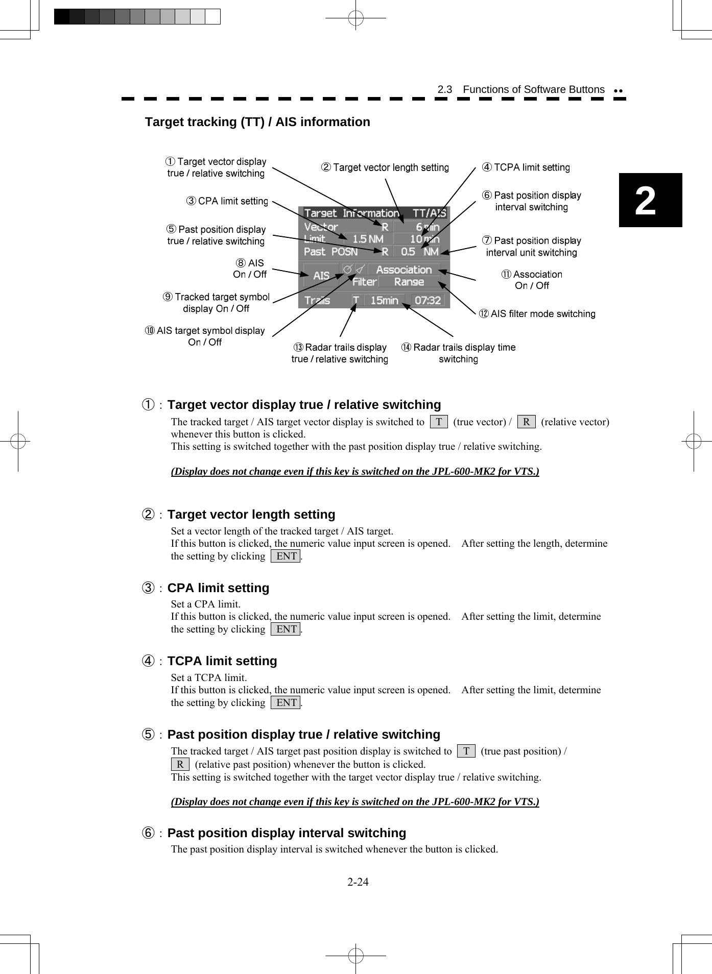
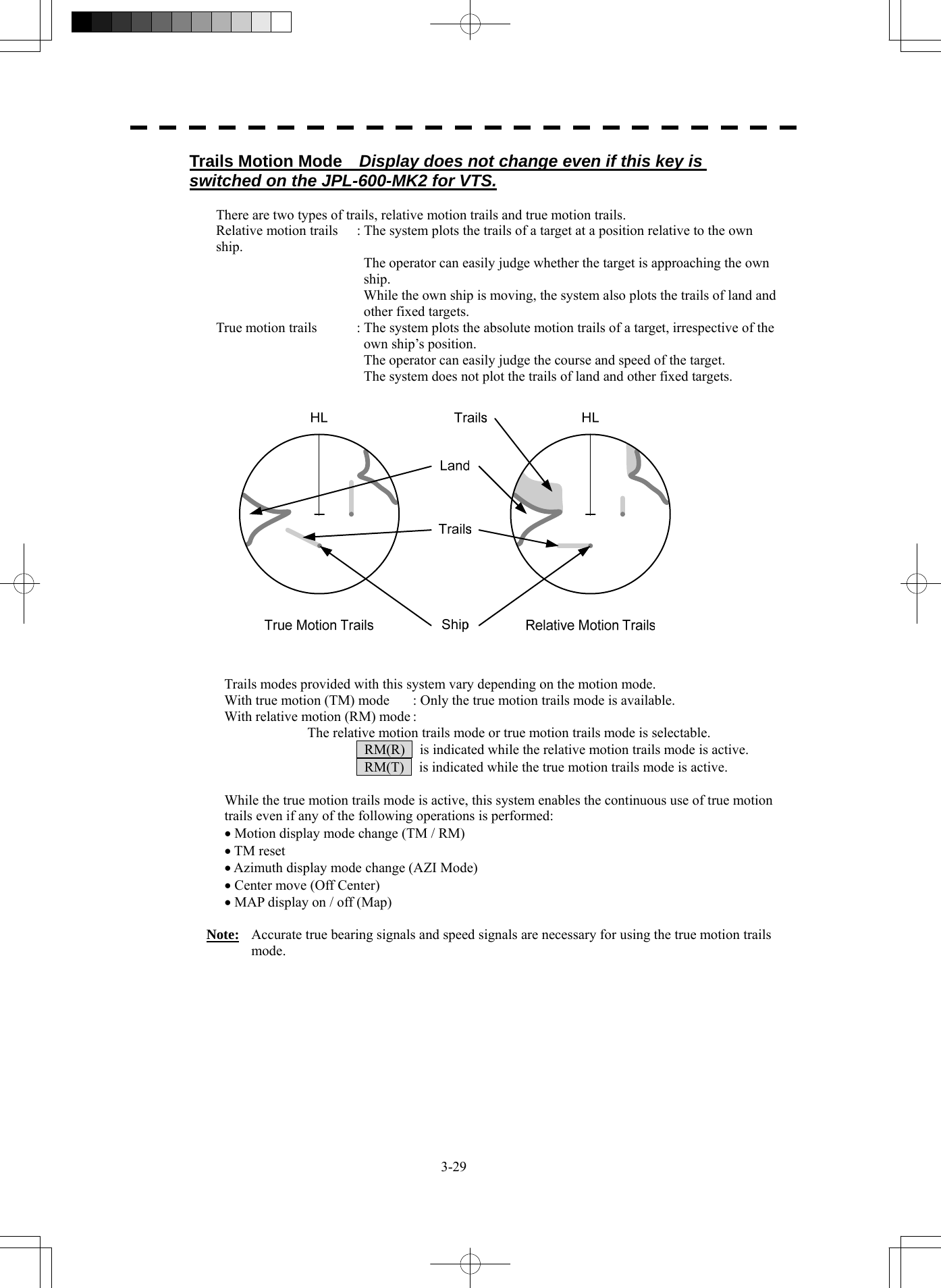
![3-28 3.4 General Radar Operation yy y3 3.4.8 Display Radar Trails [TRAILS] Ship's movements and speeds can be monitored from the lengths and directions of their trails, serving for collision avoidance. The trail length varies according to setting. Changing the length of the trail Procedures 1 Press the [TRAILS] key. Values of the length of the radar trail are switched. Trails length setting: Short mode Off ⇒ 15sec ⇒ 30sec ⇒ 1min ⇒ 3min ⇒ 6min ⇒ ⇒ 10min ⇒ 15min ⇒ Off Short: : 15 sec, 30 sec, 1 min, 3 min, 6 min, 10 min, and 15 min Middle: : 30 sec, 1 min, 3 min, 6 min, 10 min, 15 min, and 30 min Long: : 1 min, 3 min, 6 min, 10 min, 15 min, 30 min, and 1 hr Super Long : 30 min, 1 hr, 2 hr, 3 hr, 4 hr, 5 hr, 6 hr, 7 hr, 8 hr, 9 hr, 10 hr, 11 hr, and 12 hr Saved trails cannot be erased even when the trail lengths are changed by using [TRAILS] key. Even after the trails display is turned off, the past trails can be displayed traced back by setting a desired time. The radar system is start transmission, trails is start plot. The system is plotting trails even while the trails display is off. If the transmit time is short, the indicated trails duration may not have achieved the specified time. The radar trails remaining time is indicated at the right of the trails length setting. Erasing Trails Data Procedures 1 Press the [TRAILS] key for 5 seconds. All the saved trails data will be erased. The system starts plotting trails in initial state. If [TRAILS] key is pressed for 2 seconds, the RADAR Trails Setting menu is opened. Furthermore, data will be erased if it continues pressing.](https://usermanual.wiki/Japan-Radio/NKE2254.Users-Manual/User-Guide-1510215-Page-123.png)
![3-30 3.4 General Radar Operation yy y3 Changing Motion Mode of Trails (Trails mode) Display does not change even if this key is switched on the JPL-600-MK2 for VTS. Procedures 1 Put the cursor on radar trails display true / relative switching (TT / AIS information ⑬ on page 2-23), and press the [ENT] key. The trails motion modes are switched. T ⇒ R ⇒ T 3.4.9 Erase Part of Radar Trails (Trails Erase) A part of the radar trails can be erased. Procedures 1 Press the [TRAILS] key for 2 seconds. The RADAR Trails Setting menu will appear. 2 Open the Trails Erase menu by performing the following menu operation. 7. Trails Erase 3 Press the [3] key. The Erase Size switches. 2x2 : 2x2 pixels 4x4 : 4x4 pixels 8x8 : 8x8 pixels 16x16 : 16x16 pixels 32x32 : 32x32 pixels 4 Press the [1] key. The Trails Erase Mode is set to On . A square cursor □ will appear at the location of own ship. 5 Put the cursor on the position where you want to start erasing, and press the [2] key. The Trails Erase Start function is selected and trails start to be erased. Moving the cursor will erase that portion of the trails. 6 To finish erasing the trails, press the [2] key. The trails erase operation is terminated. 7 Press the [1] key. The Trails Erase Mode is set to Off .](https://usermanual.wiki/Japan-Radio/NKE2254.Users-Manual/User-Guide-1510215-Page-125.png)
![3-31 3.4.10 Operate Radar Trails File (File Operations) [I] Loading radar trails (Load RADAR Trails) Procedures 1 Insert a flash memory card into the card slot. Flash memory card (option) is necessary. For the insertion and removal of the card, see HOW TO INSERT AND REMOVE A CARD in the appendix. 2 Press the [TRAILS] key for 2 seconds. The RADAR Trails Setting menu will appear. 3 Open the File Operations menu by performing the following menu operation. 8. File Operations 4 Press the [1] key to select a card slot. Slot1 and Slot2 of the Select Card Slot items are switched. 5 Press the [2] key. The list of radar trails saved in the card will be displayed. 6 Press numeric keys corresponding to the desired file. Confirmation Window will appear. 7 Press the [1] key. The selected radar trails data is loaded and displayed of the display. [II] Saving radar trails (Save RADAR Trails) Procedures 1 Insert a flash memory card into the card slot. Flash memory card (option) is necessary. For the insertion and removal of the card, see HOW TO INSERT AND REMOVE A CARD in the appendix. 2 Press the [TRAILS] key for 2 seconds. The RADAR Trails Setting menu will appear. 3 Open the File Operations menu by performing the following menu operation. 8. File Operations 4 Press the [1] key to select a card slot. Slot1 and Slot2 of the Select Card Slot items are switched.](https://usermanual.wiki/Japan-Radio/NKE2254.Users-Manual/User-Guide-1510215-Page-126.png)
![3-32 3.4 General Radar Operation yy y3 5 Press the [3] key. The Input File Name screen will appear. 6 Enter the file name to be saved. Up to 15 characters can be entered. For the input method on the character input screen, see Section 3.3.4. After characters have been entered, Confirmation Window will appear. 7 Press the [1] key. Radar trails data currently being displayed is saved. [III] Erasing save radar trails (Erase RADAR Trails) Procedures 1 Insert a flash memory card into the card slot. Flash memory card (option) is necessary. For the insertion and removal of the card, see HOW TO INSERT AND REMOVE A CARD in the appendix. 2 Press the [TRAILS] key for 2 seconds. The RADAR Trails Setting menu will appear. 3 Open the File Operations menu by performing the following menu operation. 8. File Operations 4 Press the [1] key to select a card slot. Slot1 and Slot2 of the Select Card Slot items are switched. 5 Press the [4] key. The File Erase menu will appear. The list of radar trails saved in the card will be displayed. 6 Press numeric keys corresponding to the desired file number. Confirmation Window will appear. 7 Press the [1] key. The selected radar trails data is erased and the name of the radar trails data is deleted from the list.](https://usermanual.wiki/Japan-Radio/NKE2254.Users-Manual/User-Guide-1510215-Page-127.png)
![3-33 3.4.11 Zoom (x2) This function doubles the size of radar video near a specified position. Note: If the range is 0.125 NM or motion mode is true motion mode (TM), this function is not available. Procedures 1 Put the cursor on double zoom switching x2 (lower left of the display ① on page 2-18), and press the [ENT] key. The zoom mode is selected. 2 Put the cursor on the position to be zoomed, and then press the [ENT] key. The zoom is set. Using the cross cursor mark as reference, the zoom function doubles the size of a radar video with the midpoint between the cursor mark and own ship’s position being set to the center of radar display. Cancellation 1 Put the cursor on double zoom switching x2 (lower left of the display ① on page 2-18), and press the [ENT] key. The zoom mode is cancelled. 3.4.12 Hide / Display Scanner Heading Line (RR / HL) Procedures 1 Press the [RR / HL] key for 2 seconds or more. The scanner heading line (HL) is hidden while the [RR / HL] key is held down. Because the scanner heading line disappears while this key is held down, it becomes easier to see target objects in the scanner heading direction.](https://usermanual.wiki/Japan-Radio/NKE2254.Users-Manual/User-Guide-1510215-Page-128.png)
![3-34 3.4 General Radar Operation yy y3 3.4.13 Hide Graphics Information on Radar Display (Data Off) Various graphics information such as target tracking (TT) / AIS symbols, NAV lines, and MAP information is shown of the display of this radar system, and may make it difficult to view the radar video. In that case, use this function to temporarily hide unnecessary graphics information. Procedures 1 Put the cursor on graphic display Off Data Off (lower right on the display ⑤ on page 2-21), and press the [ENT] key. While the key is pressed, graphics data other than VRM, EBL, HL, cursor mark, and range rings of the display is temporarily hidden. 3.4.14 Switch Day / Night Mode [DAY / NIGHT] Several combinations of the display color and brilliance according to the ambient lighting conditions are provided. The display color setting is easily changed. Procedures 1 Press the [DAY / NIGHT] key. The Day / Night modes are switched. Day1 ⇒ Day2 ⇒ Day3 ⇒ Dusk ⇒ Night ⇒ Dusk ⇒ Day3 ⇒ Day2 ⇒ Day1 The current mode is displayed in the Day / Night mode switching (brilliance / Alarm ⑤ on page 2-28). For how to set the display color and brilliance for each mode, see Section 3.8.6. 3.4.15 Adjust Operation Panel Brilliance [PANEL] Adjust brilliance of the operation panel according to the ambient lighting conditions. Procedures 1 Press the [PANEL] key. In consideration of the ambient brightness, adjust panel brilliance that is high enough to read the characters on the operation panel but does not glare. The [PANEL] key lamp lights up irrespective of panel brilliance adjustment.](https://usermanual.wiki/Japan-Radio/NKE2254.Users-Manual/User-Guide-1510215-Page-129.png)
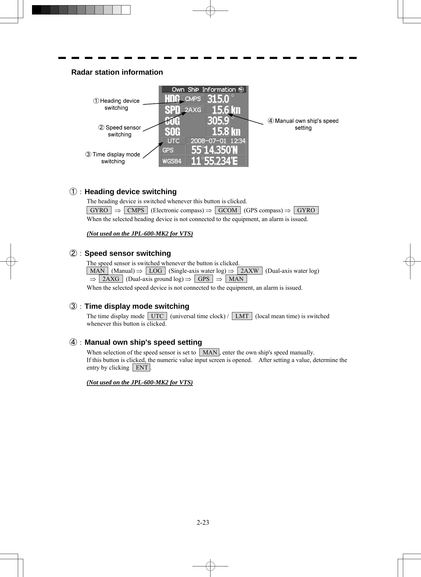
![3-35 3.4.16 Set True Bearing (GYRO Setting) (Not used on the JPL-600-MK2) When the GYRO I/F unit is used to enter a gyro signal, there is a rare case in which a true bearing value indicated by the master gyro does not match the true bearing value indicated by this radar system. In that case, adjust the true bearing value of this system so that it matches the value indicated by the master gyro. Procedures 1 Press the [AZI MODE] key for 2 seconds. The numeric value input menu for the GYRO Setting menu will appear. 2 Enter the value indicated by the master gyro. For how to input numeric data on the numeric value input menu, see Section 3.3.4. 3.4.17 Set Own Ship Speed (Not used on the JPL-600-MK2 for VTS) Switch the own ship speed device Procedures 1 Put the cursor on speed sensor switching (own ship information ② on page 2-22), and press the [ENT] key. The speed sensor is switched whenever the button is clicked. MAN (Manual) ⇒ LOG (Single-axis water log) ⇒ 2AXW (Dual-axis water log) ⇒ 2AXG (Dual-axis ground log) ⇒ GPS ⇒ MAN * If the single axis water log display can present the speed of the ship in other than the forward direction, the direction of movement should be indicated unambiguously. Therefore single axis water logs cannot detect the effect of leeway. If you selected the 2AXW, the value of forward-backward direction is indicated. If ships in shallow water, when the accuracy of the dual-axis log may be decreased. If ships in deep sea area, when the accuracy of the dual-axis log error may be occurred. The accuracy of GPS's COG is ±3° when own ships speed no fewer than 1kn, no more than 17kn. The accuracy of GPS's COG is ±1° when own ships speed over 17kn.](https://usermanual.wiki/Japan-Radio/NKE2254.Users-Manual/User-Guide-1510215-Page-130.png)
![3-36 3.4 General Radar Operation yy y3 Input the own ship speed (Manual Speed) If the ship-speed system, such as LOG, etc., connected to this radar system malfunctions, it is possible to manually enter own ship speed by the method described below to use the target tracking (TT) and true motion display functions. Procedures 1 Put the cursor on speed sensor switching (own ship information ② on page 2-22), and press the [ENT] key to select manual mode MAN . 2 Put the cursor on manual own ship's speed setting (own ship information ④ on page 2-22), and press the [ENT] key. The numeric value input screen for the Manual Speed menu will appear. 3 Enter the value of own ship speed. For how to input numeric data on the numeric value input screen, see Section 3.3.4. 3.4.18 Magnet Compass Correction (MAG Compass Setting) (Not used on the JPL-600-MK2) Set the correction value, when the radar receive HDM sentence from magnet compass or the variation of HDG is NULL. Procedures 1. Press the [RADAR MENU] key twice. 2 Open the MAG Compass Setting menu by performing the following menu operation. 4. NAV equipment Setting → 2. MAG Compass Setting 2. Press the [1] key. The Heading Correction function can be turned on / off. Off : Heading correction is not conducted. On : Heading correction is conducted. 3. Press the [2] key. The correction set numeric value input menu will appear. 4. Input the correction value. Press the + or - button to select south and north for latitude or the east and west for longitude. For how to input numeric data on the numeric value input screen, see Section 3.3.4.](https://usermanual.wiki/Japan-Radio/NKE2254.Users-Manual/User-Guide-1510215-Page-131.png)
![3-37 3.4.19 Set Drift Correction (Set / Drift Setting) (Not used on the JPL-600-MK2) The direction and speed of the drift are set. This function can be used only when MAN or LOG is selected for ship-speed data. Procedures 1 Press the [RADAR MENU] key twice. 2 Open the Set / Drift Setting menu by performing the following menu operation. 4. NAV Equipment Setting → 3. Set/Drift Setting 3 Press the [1] key. The Correction function can be turned on / off. Off : Drift correction is not conducted. On : Drift correction is conducted. 4 Press the [2] key. The direction set numeric value input menu will appear. 5 Enter the value of the drift direction (true bearing). For how to input numeric data on the numeric value input menu, see Section 3.3.4. 6 Press the [3] key. The drift speed numeric value input menu will appear. 7 Enter the value of the drift speed. For how to input numeric data on the numeric value input menu, see Section 3.3.4.](https://usermanual.wiki/Japan-Radio/NKE2254.Users-Manual/User-Guide-1510215-Page-132.png)
![3-38 3.4 General Radar Operation yy y3 3.4.20 GPS Receiver Setting (GPS Process Setting) Set to a JRC’s GPS receiver. This setting is enabled when a JRC’s GPS is connected to the GPS connector of processor unit. [I] Radar station position setting (Position) Initial position fixing speeds up by entering an approximate position of the radar station. Procedures 1. Press the [RADAR MENU] key twice, and then perform the following menu open procedure to open the Position menu. 4. NAV equipment Setting → 4. GPS Setting → 1. GPS Process Setting → 1. Position 2. Enter the own ship’s position in the numeric value input menu. For the input method on the latitude / longitude input screen, see Section 3.3.4. 3. Press the [9] key to send the setting value to GPS receiver. [Ⅱ] Satellite exclusion setting (Exclusion) Procedures 1. Press the [RADAR MENU] key twice, and then perform the following menu open procedure to open the Exclusion menu. 4. NAV Equipment Setting → 4. GPS Setting → 1. GPS Process Setting → 2. Exclusion 2. Enter the satellite exclusion number in the numeric value input menu. For the input method on the numeric value input screen, see Section 3.3.4. 3. Press the [9] key to send the setting value to GPS receiver.](https://usermanual.wiki/Japan-Radio/NKE2254.Users-Manual/User-Guide-1510215-Page-133.png)
![3-39 [Ⅲ] Geodetic system setting (Geodetic) This menu is used to set the geodetic system of the radar station position. Procedures 1. Press the [RADAR MENU] key twice, and then perform the following menu open procedure to open the Geodetic menu. 4. NAV Equipment Setting → 4. GPS Setting → 1. GPS Process Setting → 3. Geodetic 2. Enter the geodetic system number in the numeric value input menu refer to next page. 3. Press the [9] key to send the setting value to GPS receiver. [Ⅳ] Antenna height setting (Antenna height) Procedures 1. Press the [RADAR MENU] key twice, and then perform the following menu open procedure to open the Antenna Height menu. 4. NAV Equipment Setting → 4. GPS Setting → 1. GPS Process Setting → 4. Antenna height 2. Enter the GPS antenna height in the numeric value input menu. 3. Press the [9] key to send the setting value to GPS receiver. [Ⅴ] Fix mode setting (Fix mode) Procedures 1. Press the [RADAR MENU] key twice, and then perform the following menu open procedure to open the Fix Mode menu. 4. NAV Equipment Setting → 4. GPS Setting → 1. GPS Process Setting → 5. Fix Mode 2. Select the fix mode. 2D : height is measured in two dimensions 3D : height is measured in three dimensions AUTO :select the proper dimension to measure a height automatically 3. Press the [9] key to send the setting value to GPS receiver.](https://usermanual.wiki/Japan-Radio/NKE2254.Users-Manual/User-Guide-1510215-Page-134.png)
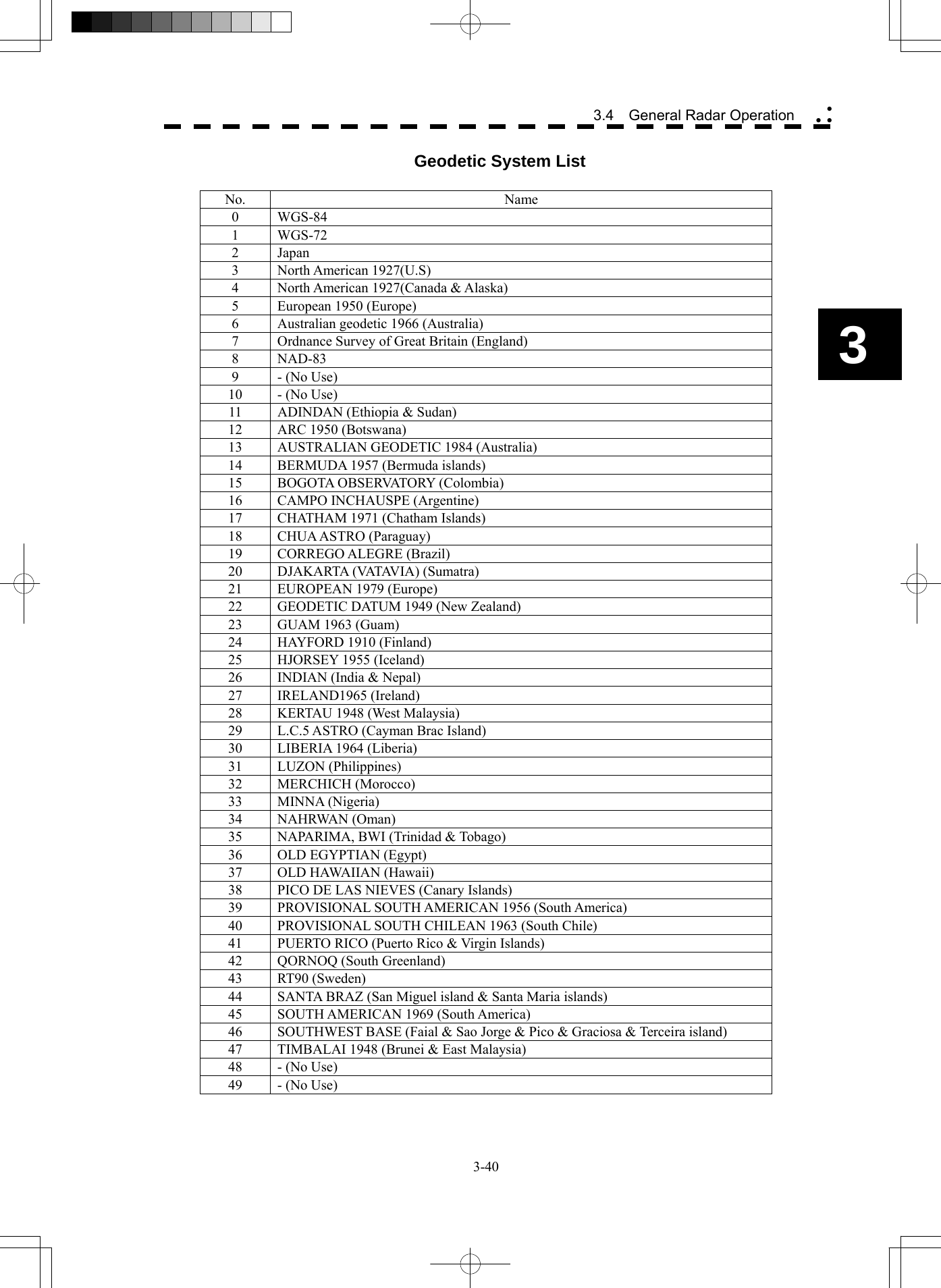
![3-41 [Ⅵ] HDOP level setting (DOP Level) Procedures 1. Press the [RADAR MENU] key twice, and then perform the following menu open procedure to open the DOP Level menu. 4. NAV Equipment Setting → 4. GPS Setting → 1. GPS Process Setting → 6. DOP Level 2. Enter the HDOP level in the numeric value input menu. When the HDOP level is decrease, the accuracy is increased. But it is hard to measure the position. 3. Press the [9] key to send the setting value to GPS receiver. [Ⅶ] Position average time setting (Position Average) Procedures 1. Press the [RADAR MENU] key twice, and then perform the following menu open procedure to open the Position Average menu. 4. NAV Equipment Setting → 4. GPS Setting → 1. GPS Process Setting → 7. Position Average 2. Set the position average time. The following are provided according to the ROM version of GPS receiver. ROM Version R26.00: Select the average time LONG (40 sec) STANDARD (10 sec) NONE (2 sec) Other ROM Version: Enter the average time When the average time is short, the renewal speed is increased. But the stability become worse. 3. Press the [9] key to send the setting value to GPS receiver.](https://usermanual.wiki/Japan-Radio/NKE2254.Users-Manual/User-Guide-1510215-Page-136.png)
![3-42 3.4 General Radar Operation yy y3 [Ⅷ] Master reset Procedures 1. Press the [RADAR MENU] key twice, and then perform the following menu procedure to set the Master Reset On. 4. NAV Equipment Setting → 4. GPS Setting → 1. GPS Process Setting → 8. Master Reset 2. Press the [9] key to send the setting value while the master reset is on. 3.4.21 DGPS Receiver Setting (DGPS Setting) Set to a JRC’s DGPS receiver. This setting is enabled when a JRC’s DGPS is connected to the GPS connector of processor unit. [I] Beacon frequency mode setting (Mode) Procedures 1. Press the [RADAR MENU] key twice, and then perform the following menu open procedure to open the DGPS Setting menu. 4. NAV equipment Setting → 4. GPS Setting → 2. DGPS Setting 2. Press the [1] key to select the beacon frequency mode. AUTO : The beacon frequency mod is selected automatically Manual : The beacon frequency mod is selected manually 3. Press the [5] key to send the setting value to DGPS receiver. [Ⅱ] Beacon frequency setting(Frequency) This setting is enabled when beacon frequency mode is set to manual. Procedures 1. Press the [RADAR MENU] key twice, and then perform the following menu open procedure to open the Frequency menu. 4. NAV equipment Setting → 4. GPS Setting → 2. DGPS Setting → 2. Frequency 2. Enter the beacon frequency. 3. Press the [5] key to send the setting value to DGPS receiver.](https://usermanual.wiki/Japan-Radio/NKE2254.Users-Manual/User-Guide-1510215-Page-137.png)
![3-43 [Ⅲ] baud rate setting(Baud Rate(BPS)) This setting is enabled when beacon frequency mode is set to manual. Procedures 1. Press the [RADAR MENU] key twice, and then perform the following menu open procedure to open the Baud Rate menu. 4. NAV equipment Setting → 4. GPS Setting → 2. DGPS Setting → 3. Baud Rate(BPS) 2. Select the baud rate. Following baud rate is selectable 50 bps/100 bps/200 bps 3. Press the [5] key to send the setting value to DGPS receiver. [Ⅳ] DGPS Mode setting(DGPS Mode) When DGPS mode set to on, DGPS use the information from beacon to get reliable position. When DGPS mode set to off, the accuracy of position is same as GPS. Procedures 1. Press the [RADAR MENU] key twice, and then perform the following menu open procedure to open the DGPS Mode menu. 4. NAV equipment Setting → 4. GPS Setting → 2. DGPS Setting 2. Press [4] key to select the DGPS Mode. On : DGPS use the information from beacon Off : DGPS don’t use the information from beacon 3. Press the [5] key to send the setting value to DGPS receiver. 3.4.22 SBAS Receiver Setting (SBAS Setting) Set to a JRC’s SBAS receiver. SBAS receiver use the information from satellite same as that of beacon which DGPS use. So the accuracy of position is higher than GPS. This setting is enabled when a JRC’s DGPS is connected to the GPS connector of processor unit. [I] SBAS mode setting (Mode) Select the satellite or the beacon whose differential information is used.](https://usermanual.wiki/Japan-Radio/NKE2254.Users-Manual/User-Guide-1510215-Page-138.png)
![3-44 3.4 General Radar Operation yy y3 Procedures 1. Press the [RADAR MENU] key twice, and then perform the following menu open procedure to open the Mode menu. 4. NAV equipment Setting → 4. GPS Setting → 3. SBAS Setting → 1. Mode 2. Select the satellite or the beacon whose differential information is used. Beacon : SBAS receiver use the information from beacon SBAS : SBAS receiver use the information from SBAS satellite AUTO : SBAS receiver selects automatically 3. Press the [6] key to send the setting value to SBAS receiver. [Ⅱ] Ranging satellite setting (Ranging) Set the SBAS satellite to be used or not to be used. Procedures 1. Press the [RADAR MENU] key twice, and then perform the following menu open procedure to open the SBAS Setting menu. 4. NAV equipment Setting → 4. GPS Setting → 3. SBAS Setting 2. Press [2] key to select the SBAS satellite to be used or not to be used. On : SBAS satellite is used Off : SBAS satellite is not used 3. Press the [6] key to send the setting value to SBAS receiver. [Ⅲ] Prohibitive satellite setting (NG SBAS) Set the information from prohibitive SBAS satellite to be used or not to be used. Procedures 1. Press the [RADAR MENU] key twice, and then perform the following menu open procedure to open the SBAS Setting menu. 4. NAV equipment Setting → 4. GPS Setting → 3. SBAS Setting 2. Press [3] key to select the information from prohibitive SBAS satellite to be used or not to be used. On : The information from prohibitive SBAS satellite is used Off : The information from prohibitive SBAS satellite is not used 3. Press the [6] key to send the setting value to SBAS receiver.](https://usermanual.wiki/Japan-Radio/NKE2254.Users-Manual/User-Guide-1510215-Page-139.png)
![3-45 [Ⅳ] Satellite number select mode setting (SBAS Select Mode) Set the satellite number select mode. Procedures 1. Press the [RADAR MENU] key twice, and then perform the following menu open procedure to open the SBAS Setting menu. 4. NAV equipment Setting → 4. GPS Setting → 3. SBAS Setting 2. Press [4] key to select the satellite number select mode. Manual : SBAS satellite number is set manually AUTO : SBAS satellite number is set automatically 3. Press the [6] key to send the setting value to SBAS receiver. [Ⅴ] Satellite number setting (SBAS No.) Set the satellite number. This setting is enabled when satellite number select mode is set to manual. Procedures 1. Press the [RADAR MENU] key twice, and then perform the following menu open procedure to open the SBAS No. menu. 4. NAV equipment Setting → 4. GPS Setting → 3. SBAS Setting → 5. SBAS No. 2. Enter the satellite number. Enter the number from 120 to 138. 3. Press the [6] key to send the setting value to SBAS receiver.](https://usermanual.wiki/Japan-Radio/NKE2254.Users-Manual/User-Guide-1510215-Page-140.png)
![3-46 3.4 General Radar Operation yy y3 3.4.23 Displaying GPS Reception Status (GPS Status) The reception status of GPS(GPS/DGPS/WAAS) which is connected to radar processor unit is displayed. This setting is enabled when a JRC’S GPS/DGPS/WAAS is connected to the GPS connector of processor unit. Procedures 1. Press the [RADAR MENU] key twice, and then perform the following menu open procedure to open the GPS Status window. 4. NAV equipment Setting → 4. GPS Status 2. After check of the GPS status, press [0] key to close the GPS status window. This window cannot be opened in the transmission state.](https://usermanual.wiki/Japan-Radio/NKE2254.Users-Manual/User-Guide-1510215-Page-141.png)
![3-47 3.4.24 Set Radar Alarm (RADAR Alarm) The radar alarm can be issued when targets have entered the radar alarm range. Turning on / off the radar alarm (Sector RADAR Alarm) Procedures 1 Press the [AZ] key for 2 seconds. The AZ Menu will appear. 2 Open the Sector RADAR Alarm menu by performing the following menu operation. 4. RADAR Alarm → 1. Sector RADAR Alarm 3 Press the [1] key or [2] key. Sector Alarm1 or Sector Alarm2 is turned on / off. On : The radar alarm is turned on. Off : The radar alarm is turned off. Change the Radar Alarm Setting (RADAR Alarm Mode) Procedures 1 Press the [AZ] key for 2 seconds. The AZ Menu will appear. 2 Open the Sector RADAR Alarm menu by performing the following menu operation. 4. RADAR Alarm 3 Press the [5] key. Sector Alarm1 or Sector Alarm2 is turned on / off. In : When a target has entered the zone, RADAR Alarm (In) is issued. Out : When a target has departed the zone, RADAR Alarm (Out) is issued. 4 Press the [6] key. Selected items for Sensitivity Level will be displayed. 5 Press numeric keys corresponding to the Sensitivity Level. The threshold video level increases in order of Level1 → Level2 → Level3 → Level4 .](https://usermanual.wiki/Japan-Radio/NKE2254.Users-Manual/User-Guide-1510215-Page-142.png)
![3-48 3.4 General Radar Operation yy y3 Creating the radar alarm zone (Make Sector Alarm) Procedures 1 Press the [AZ] key for 2 seconds. The AZ Menu will appear. 2 Open the Make Sector Alarm menu by performing the following menu operation. 4. RADAR Alarm → 3. Make Sector Alarm 3 Press the [1] key or [2] key. The range setting for Sector Alarm1 or Sector Alarm2 starts. 4 Turn the [EBL] dial and the [VRM] dial to set the start bearing and the start range, and then press the [ENT] key. 5 Turn the [EBL] dial and the [VRM] dial to set the end bearing and the end range, and then press the [ENT] key. The radar alarm zone is determined. Setting the [AZ] key allocation (Set AZ Key) Only by pressing the [AZ] key, the normally-used radar alarm can be easily turned on / off. Procedures 1 Press the [AZ] key for 2 seconds. The AZ Menu will appear. 2 Open the Sector RADAR Alarm menu by the following menu operation. 5. Set AZ Key → 2. Sector RADAR Alarm 3 Set the [AZ] key allocation. On : Pressing the [AZ] key will turn on or off the radar alarm. Off : Even if the [AZ] key is pressed, the radar alarm zone is not turned on. Note: When the automatic acquisition / activation zone key allocation is set, pressing the [AZ] key will simultaneously turn on or off the radar alarm in the automatic acquisition / activation zone.](https://usermanual.wiki/Japan-Radio/NKE2254.Users-Manual/User-Guide-1510215-Page-143.png)
![3-49 3.5 USE OWN SHIP'S TRACK DATA (Not used on the JPL-600-MK2 for VTS) The own ship's track function saves and displays own ship's track. If navigation equipment is connected, this radar system records latitude / longitude data sent from the navigation equipment and displays own ship's track. Note: Even when own ship's track interval switching (lower right of the display ③ on page 2-21) is set to Off , own ship's track can be displayed. However, in this case, if rewrite operation such as changing of the display range is performed for the radar display, own ship's track display is erased and the track will not be plotted again. If the DISP Own Track is turned off when the own ship track is in save, own ship's track is not shown of the display, but own ship's track data is still saved. When a plotter unit (optional) is connected, own ship's track can be displayed and saved in seven different colors. The color display can be turned on or off by color. 3.5.1 Display Own Ship’s Track (Display Own Track) Procedures 1 Open the Own Track Menu by the following menu operation. O.TRK 2 Press the [1] key. The DISP Own Track function item is turned on or off. On : Own ship's track is displayed. Off : Own ship's track is not displayed. 3 Press the [MAP] key. The map display function is turned on or off. Selecting On will display own ship's track.](https://usermanual.wiki/Japan-Radio/NKE2254.Users-Manual/User-Guide-1510215-Page-144.png)
![3-50 3.5 Use Own ship's track data yy y3 3.5.2 Save Own Ship's Track Data (Own Track Memory) To save own ship's track data, save at a specified time interval and at a specified range interval can be selected. The data save interval can be selected from 10 preset time intervals and 8 preset range intervals. Save intervals that can be selected Time : 3 sec, 5 sec, 10 sec, 30 sec, 1 min, 3 min, 5 min, 10 min, 30 min, and 60 min Range : 0.1 NM, 0.2 NM, 0.3 NM, 0.5 NM, 1 NM, 3 NM, 5 NM, and 10 NM Procedures 1 Put the cursor on own ship's track interval unit switching (lower right of the display ④ on page 2-21), and press the [ENT] key. Units of own ship's track interval are switched. 2 Put the cursor on own ship's track interval switching (lower right of the display ③ on page 2-21), and press the [ENT] key. Own ship's track intervals are switched. Setting the button to Off cancels the saving of data. 3.5.3 Cancel Saving of Own Ship’s Track Data (Own Track Memory) This function cancels the saving of own ship’s track data. Procedures 1 Put the cursor on own ship's track interval switching (lower right of the display ③ on page 2-21), and press the [ENT] key. Own ship's track intervals are switched. Selecting Off will cancel the saving of data. 3.5.4 Clear Own Ship’s Track Data (Clear Own Track) This function clears own ship’s track data from memory. Procedures 1 Open the Own Track Menu by the following menu operation. O.TRK 2 Press the [2] key. Clear Own Track Confirmation Window will appear. 3 Press the [1] key. The own ship’s track data will be cleared.](https://usermanual.wiki/Japan-Radio/NKE2254.Users-Manual/User-Guide-1510215-Page-145.png)
![3-51 3.5.5 Operate Own ship's Track Files (File Operations) [I] Loading own ship's track data (Load Own Track) Procedures 1 Insert a flash memory card into the card slot. Flash memory card (option) is necessary. For the insertion and removal of the card, see HOW TO INSERT AND REMOVE A CARD in the appendix. 2 Open the File Operations menu by the following menu operation. O.TRK → 5. File Operations 3 Press the [1] key to select a card slot. Slot1 and Slot2 of the Select Card Slot items are switched. 4 Press the [2] key to select Add or Overwrite. Add and Overwrite in the Load Mode items are switched. When Add is selected, new data is added to the saved data. When Overwrite is selected, the saved data is overwritten. 5 Press the [3] key. The list of own ship's tracks data saved in the system will be displayed. 6 Press numeric keys corresponding to the file to be loaded. Confirmation Window will appear. 7 Press the [1] key. The selected own ship's track data is loaded and displayed of the display.](https://usermanual.wiki/Japan-Radio/NKE2254.Users-Manual/User-Guide-1510215-Page-146.png)
![3-52 3.5 Use Own ship's track data yy y3 [II] Saving own ship's track data (Save Own Track) Procedures 1 Insert a flash memory card into the card slot. Flash memory card (option) is necessary. For the insertion and removal of the card, see HOW TO INSERT AND REMOVE A CARD in the appendix. 2 Open the File Operations menu by performing the following menu operation. O.TRK → 5. File Operations 3 Press the [1] key to select a card slot. Slot1 and Slot2 of the Select Card Slot items are switched. 4 Press the [4] key. The character input screen for Input File Name will appear. 5 Enter the file name to be saved. Up to 10 characters can be entered. For the input method on the character input screen, see Chapter 3.3.4. After entry has been finished, Confirmation Window will appear. 6 Press the [1] key. Own ship's track data currently being displayed is saved. [III] Erasing own ship's track data (Erase Own Track) Procedures 1 Insert a flash memory card into the card slot. Flash memory card (option) is necessary. For the insertion and removal of the card, see HOW TO INSERT AND REMOVE A CARD in the appendix. 2 Open the File Operations menu by performing the following menu operation. O.TRK → 5. File Operations 3 Press the [1] key to select a card slot. Slot1 and Slot2 of the Select Card Slot items are switched. 4 Press the [5] key. The Erase screen will appear. The list of own ship's track data saved in the card will be displayed.](https://usermanual.wiki/Japan-Radio/NKE2254.Users-Manual/User-Guide-1510215-Page-147.png)
![3-53 5 Press numeric keys corresponding to the file to be deleted. Confirmation Window will appear. 6 Press the [1] key. The selected own ship's track data is deleted and the file name is deleted from the list. [IV] Displaying saved own ship's track data (Card Own Track Display) Procedures 1 Insert a flash memory card into the card slot. Flash memory card (option) is necessary. For the insertion and removal of the card, see HOW TO INSERT AND REMOVE A CARD in the appendix. 2 Open the File Operations menu by performing the following menu operation. O.TRK → 5. File Operations 3 Press the [1] key to select a card slot. Slot1 and Slot2 of the Select Card Slot items are switched. 4 Press the [6] key. The Card Own Track Display menu will appear. The list of own ship's track data saved in the card will be displayed. 5 Press numeric keys corresponding to the number for the file to be displayed. Confirmation Window will appear. 6 Press the [1] key. The saved own ship's track data will be displayed.](https://usermanual.wiki/Japan-Radio/NKE2254.Users-Manual/User-Guide-1510215-Page-148.png)
![3-54 3.6 Display User Map yy y3 3.6 DISPLAY USER MAP Up to 2,000 items (20,000 items when a plotter unit option is connected) of NAV lines, coastlines, depth contours, and NAV marks can be created, displayed, loaded, and saved. (This function is available only when navigation equipment is connected to this radar system.) If the number of items exceeds 2,000, the oldest saved items are sequentially deleted. Up to 20 items of temporarily used marks can be created and displayed. Marks that can be used : 29 types Lines that can be used : 3 types (solid, broken, and dashed-dotted line) Color of mark and line that can be used : 7 colors If radar video is poor visibility caused by user map function, press the [DATA OFF] key to map displays temporarily off. 3.6.1 Create User Map (Mark / Line) In this system, when the radar is in the transmission state, the user map is displayed all the time. However, valid latitude / longitude data and true bearing data must be entered into the system. The user map can be created and edited by performing the following operation. Plotting a mark Procedures 1 Press the [MARK] key to select the mark mode. The mark font to be used is displayed in the mark font switching (upper right of the display ② on page 2-19). 2 Put the cursor on mark font switching (upper right of the display ② on page 2-19), and press the [ENT] key. The mark fonts are switched. 3 Put the cursor mark on mark color switching C (upper right of the display ③ on page 2-19), and press the [ENT] key. The mark colors are switched. 4 Put the cursor on a location of the display at which you want to plot the mark, and press the [ENT] key. The specified mark is displayed in the specified shape and color. To create another mark, repeat the above procedures.](https://usermanual.wiki/Japan-Radio/NKE2254.Users-Manual/User-Guide-1510215-Page-149.png)
![3-55 Plotting a line Procedures 1 Press the [MARK] key to select the line mode. The line pattern to be used is displayed in the line pattern switching (upper right of the display ② on page 2-19). 2 Put the cursor on line pattern switching ------- (upper right of the display ② on page 2-19), and press the [ENT] key. Line patterns are switched. 3 Put the cursor on line color switch C (upper right of the display ③ on page 2-19), and press the [ENT] key. Line colors are switched. 4 Put the cursor on a location of the display at which you want to start plotting a line, and press the [ENT] key. The start point of the specified line will be displayed. 5 Move the cursor to a location of the display at which you want to finish plotting the line, and press the [ENT] key. A line is plotted between the previous point and the end point. Repeat this procedure so that sequential lines can be plotted. 6 When you want to finish plotting the line, press the [ENT] key at the previous point. Line plotting will be terminated. To plot another line, repeat procedures 4 to 6.](https://usermanual.wiki/Japan-Radio/NKE2254.Users-Manual/User-Guide-1510215-Page-150.png)
![3-56 3.6 Display User Map yy y3 Plotting a mark / line make with latitude and longitude Procedures 1 Open the Edit User Map menu by performing the following menu operation. Plot → 2. Mark Operations → 2. Edit User Map 2 Press the [2] key. The Make with L/L menu will appear. 3 Press the [9] key to select the New Mark Input or New Line Input. The Mark Input menu and the Line Input menu are switched. 4 Press the [1] key to select the type of mark font or line pattern to be created. The desired mark font or line pattern is selected. To add a line, select midpoint --O-- . 5 Press the [2] key to select the color of mark or line to be created. The desired mark or line color is selected. 6 Press the [3] key to input the latitude / longitude. For the input method on the latitude / longitude input screen, see Section 3.3.4. 7 Press the [4] key to input the comment. For the input method on the character input screen, see Section 3.3.4. The window will not be open when the system is in the transmission state. 8 Press the [5] key. Mark / Line plotting will be terminated. To create another mark or line, repeat procedures 4 to 8.](https://usermanual.wiki/Japan-Radio/NKE2254.Users-Manual/User-Guide-1510215-Page-151.png)
![3-57 Plotting a temporarily used mark Procedures 1 Put the cursor on a location of the display at which you want to plot a mark, and press the [CLR / INFO] key. The cursor mode list will be displayed. 2 Press the [7] key. Temporarily used marks will be displayed. To create another mark, put the cursor on a location at which you want to plot a mark, and press the [ENT] key. Up to 20 temporarily used marks can be created, but adding comments and saving data onto a card are not possible. When the power supply is turned off, the data will be deleted. When the number of temporarily used marks exceeds 20, if rewrite operation such as changing of the display range is performed for the radar display, items older than most recently plotted 20 items will not be plotted again. 3.6.2 Set User Map Display (Mark Display Setting) The user map can be individually displayed (on) or hidden (off). Setting by type : Setting can be made by mark font and line pattern. Setting by color : Setting can be made by color of mark or line. The mark font display size can be selected. Normal : The mark is displayed in normal size. Small : The mark is displayed in a size smaller than usual. Setting display by type Procedures 1 Press the [MARK] key for 2 seconds. The Mark Setting display will appear. 2 Open the Display Mark Type menu by performing the following menu operation. 1. Display Mark Type 3 Press the [1] key. Selected items for All will be displayed. 4 Press the [3] key to make Individual setting. Off : All types are not displayed. On : All types are displayed. Individual : Setting by type is activated. 5 Press numeric keys corresponding to each mark font / line pattern display. On : Displayed. Off : Not Displayed.](https://usermanual.wiki/Japan-Radio/NKE2254.Users-Manual/User-Guide-1510215-Page-152.png)
![3-58 3.6 Display User Map yy y3 Setting display by color Procedures 1 Press the [MARK] key for 2 seconds. The Mark Setting menu will appear. 2 Open the Display Mark Color menu by performing the following menu operation. 2. Display Mark Color 3 Press the [1] key. Selected items for All will be displayed. 4 Press the [3] key to make Individual setting. Off : All colors are not displayed. On : All colors are displayed. Individual : Setting by color is activated. 5 Press numeric keys corresponding to each mark font / line pattern display. On : Displayed. Off : Not Displayed. Setting the mark font size Procedures 1 Press the [MARK] key for 2 seconds. The Mark Setting display will appear. 2 Open the Select Mark Size menu by performing the following menu operation. 4. Select Mark Size 3 Press numeric keys corresponding to the mark font size to be set. Normal : The mark is displayed in normal size. Small : The mark is displayed in a size smaller than usual.](https://usermanual.wiki/Japan-Radio/NKE2254.Users-Manual/User-Guide-1510215-Page-153.png)
![3-59 Setting the character size for comments Procedures 1 Press the [MARK] key for 2 seconds. The Mark Setting menu will appear. 2 Open the Comment Font Size menu by performing the following menu operation. 5. Comment Font Size 3 Press numeric keys corresponding to the desired character size for comments. Normal : The characters for comments are displayed in normal size. Small : The characters for comments are displayed in a size smaller than usual. Clearing mark / line data (Clear Mark / Line Data) The mark / line data saved in the process unit is cleared. Procedures 1 Open the Clear Mark / Line Data menu by performing the following menu operation. Plot → 5. Clear Memory → 1. Clear Mark/Line Data 2 Press the [1] key. Confirmation Window will appear. 3 Press the [1] key. The mark / line data is deleted.](https://usermanual.wiki/Japan-Radio/NKE2254.Users-Manual/User-Guide-1510215-Page-154.png)
![3-60 3.6 Display User Map yy y3 3.6.3 Edit User Map (Edit User Map) Manually entering the radar station position (Own Ship Position) Use this function when editing navigation data for a location different from the radar station position. Procedures 1 Open the Mark Operations menu by performing the following menu operation. Plot → 2. Mark Operations 2 Press the [1] key. The latitude / longitude input menu for Radar Station Position menu will appear. 3 Enter a latitude / longitude value. For how to enter a value on the latitude / longitude input screen, see Chapter 3.3.4. The radar station position latitude / longitude value is determined. Note: The own ship's position manually entered by using the function above is valid only in the navigation data setting menu. After exciting from the menu, the manually entered position data is invalidated. Cancellation 1 Press the [0] key. The Mark Operations menu is closed, and Own Ship Position menu is cancelled. Moving a mark or line (Move) With regard to the created user map, a mark or line is moved individually. Procedures 1 Open the Edit User Map menu by performing the following menu operation. Plot → 2. Mark Operations → 2. Edit User Map 2 Press the [3] key. The user map move mode is selected. Move is displayed in the cursor mode (upper right of the display on page 2-3). 3 Put the cursor on a mark or line, and press the [ENT] key. When a mark or line to be moved is selected, the cross cursor mark will appear.](https://usermanual.wiki/Japan-Radio/NKE2254.Users-Manual/User-Guide-1510215-Page-155.png)
![3-61 4 Move the cursor mark to the destination, and press the [ENT] key. The selected mark or line is moved to the destination. To move another mark or line, repeat procedures 3 and 4. 5 When finished with the correction of lines and marks, press the [0] key. The cursor mode changes to the normal operation mode, terminating the user map move mode. (Example) Deleting a mark or line (Delete) With regard to the created user map, a mark or line is deleted individually. Procedures 1 Open the Edit User Map menu by performing the following menu operation. Plot → 2. Mark Operations → 2. Edit User Map 2 Press the [4] key. The user map delete mode is selected. Delete Map is displayed in the cursor mode (upper right of the display on page 2-3). 3 Put the cursor on a mark or line, and press the [ENT] key. The selected mark or line is deleted. To delete another mark or line, repeat procedures 3. 4 When finished with the correction of lines and marks, press the [0] key. The cursor mode changes to the normal operation mode, terminating the user map delete mode.](https://usermanual.wiki/Japan-Radio/NKE2254.Users-Manual/User-Guide-1510215-Page-156.png)
![3-62 3.6 Display User Map yy y3 Inserting a vertex into a line (Insert / Move Vertex) With regard to the created user map, a vertex is inserted into a line. Procedures 1 Open the Edit User Map menu by performing the following menu operation. Plot → 2. Mark Operations → 2. Edit User Map 2 Press the [5] key. The user map insert / move mode is selected. Insert/Move is displayed in the cursor mode (upper right of the display on page 2-3). 3 Put the cursor to a side line into which a vertex will be inserted, and press the [ENT] key. A vertex is inserted into the selected line, and the cross cursor mark will be displayed. 4 Move the cross cursor mark to the newly inserted vertex, and press the [ENT] key. To insert another vertex, repeat procedures 3 and 4. 5 When finished with the insertion of all vertices, press the [0] key. The cursor mode changes to the normal operation mode, terminating the user map insert / move mode. (Example) The side line into which a vertex is insertedInserted vertex](https://usermanual.wiki/Japan-Radio/NKE2254.Users-Manual/User-Guide-1510215-Page-157.png)
![3-63 Correcting the mark or vertex of a line (Insert / Move Vertex) With regard to the created user map, a mark or line is corrected. Procedures 1 Open the Edit User Map menu by performing the following menu operation. Plot → 2. Mark Operations → 2. Edit User Map 2 Press the [5] key. The user map insert / move mode is selected. Insert / Move is displayed in the cursor mode (upper right of the display on page 2-3). 3 Put the cursor on the mark or vertex of a line, and press the [ENT] key. When the mark or vertex of a line to be corrected is selected, the cross cursor mark will appear. 4 Move the cross cursor mark to the destination, and press the [ENT] key. The vertex of the selected mark or vertex of a line is moved to the destination. To correct another mark or vertex of a line, repeat procedures 3 and 4. 5 When finished with the correction of all vertices, press the [0] key. The cursor mode changes to the normal operation mode, terminating the user map insert / move mode. (Example) Original vertexNew vertex](https://usermanual.wiki/Japan-Radio/NKE2254.Users-Manual/User-Guide-1510215-Page-158.png)
![3-64 3.6 Display User Map yy y3 Deleting a mark or vertex of a line (Delete Vertex) With regard to the created user map, a vertex is deleted individually from a mark or line. Procedures 1 Open the Edit User Map menu by performing the following menu operation. Plot → 2. Mark Operations → 2. Edit User Map 2 Press the [6] key. The user map delete mode is selected. Delete is displayed in the cursor mode (upper right of the display on page 2-3). 3 Put the cursor on the mark or vertex of a line, and press the [ENT] key. The vertex of the selected mark or vertex of a line is deleted. All of the lines drawn by joining two points are deleted. To delete another mark or vertex of a or line, repeat procedure 3. 4 When finished with the correction of all vertices, press the [0] key. The cursor mode changes to the normal operation mode, terminating the user map delete mode. (Example) The vertex to be deleted](https://usermanual.wiki/Japan-Radio/NKE2254.Users-Manual/User-Guide-1510215-Page-159.png)
![3-65 Batch clearing marks or lines (Clear by Type by Color) With regard to the created user map, marks or lines are batch cleared by type or by color. Procedures 1 Open the Edit User Map menu by performing the following menu operation. Plot → 2. Mark Operations → 2. Edit User Map 2 Press the [7] key to select the type of marks or lines to be deleted. Select the type of marks or lines to be deleted. To select all types, select All . For example, to delete "red ○" marks, select ○ . 3 Select the color of the marks or lines to be deleted. Select the color of marks or lines to be deleted. To select all colors, select All . For example, to clear "red ○" marks, select Red . After the items have been selected, Confirmation Window will appear. 4 Press the [1] key. Selected marks or lines will be batch cleared. Note: If data is not copied on the flash memory card (option), the data is not be reloaded.](https://usermanual.wiki/Japan-Radio/NKE2254.Users-Manual/User-Guide-1510215-Page-160.png)
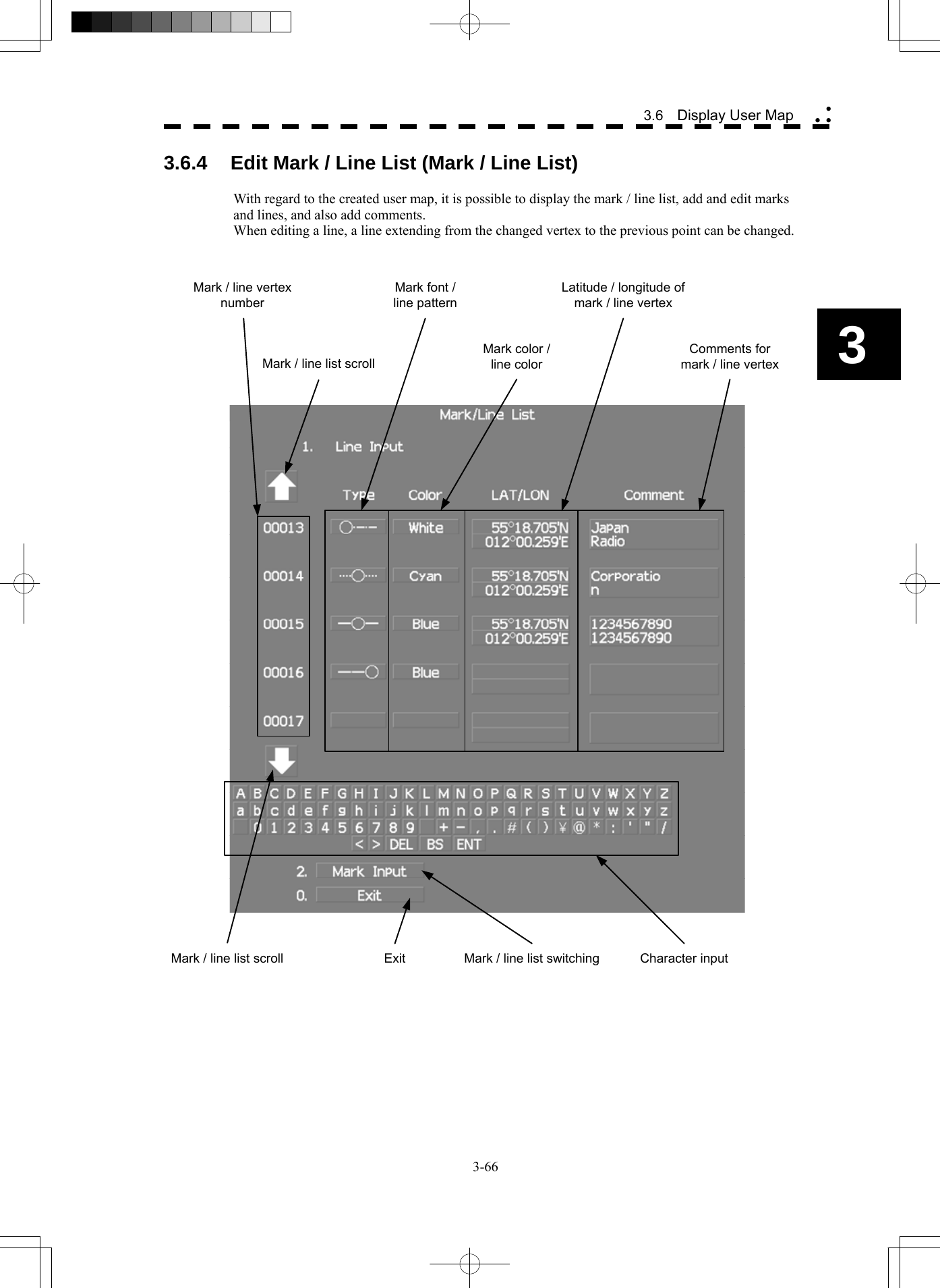
![3-67 Procedures 1 Open the Mark Operations menu by performing the following menu operation. Plot → 2. Mark Operations 2 Press the [STBY] key. The transmission standby state is selected. 3 Press the [5] key. The Mark/Line Entry menu will appear. 4 Select an item to be edited. For batch entry, select whether to enter the latitude / longitude and comments. For new entry, select LAT / LON or LAT / LON + Comment . LAT / LON : Latitude / longitude can be entered. Comment : Comments can be entered. LAT / LON + Comment : Both latitude / longitude and comments can be entered. 5 Press the [6] key. The Mark/Line List menu will appear. This window cannot be opened in the transmission state.](https://usermanual.wiki/Japan-Radio/NKE2254.Users-Manual/User-Guide-1510215-Page-162.png)
![3-68 3.6 Display User Map yy y3 Creating marks and lines Procedures 1 Open the Mark / Line List menu. 2 Press the [2] key to select the mark list or line list. The Mark Input menu and the Line Input menu are switched. 3 Press the [1] key. The input list will appear. 4 Turn the [MULTI] dial to show a vacant number in reverse video. Holding down the [RANGE + / - ] key for at least two seconds will enable scroll. Even if a mark or line is created for a vacant number, the created mark or line is listed at the end of the current mark / line list. 5 Press the [MULTI] dial. The list of the mark font or the line pattern will be displayed. 6 Press numeric keys corresponding to the desired mark font or the line pattern. The desired mark font or line pattern is selected. 7 In the same manner, enter the color of the mark or line, latitude / longitude, and comments. Use the numeric keys, latitude / longitude input screen, and the character input screen for entry. For the input method on the latitude / longitude and character input screens, see Section 3.3.4. To create another mark or line, repeat procedures 2 to 5.](https://usermanual.wiki/Japan-Radio/NKE2254.Users-Manual/User-Guide-1510215-Page-163.png)
![3-69 Adding a line With regard to the created user map, a vertex is added to the end of the line. Procedures 1 Open the input list for the Mark / Line List menu. 2 Press the [2] key to select the line list. The Mark Input menu and the Line Input menu are switched. 3 Press the [1] key. The input list will appear. 4 Turn the [MULTI] dial to show the number for the end point of a desired line ……○ in reverse video. Holding down the [RANGE + / - ] key for at least two seconds will enable scroll. 5 Press the [MULTI] dial. The list of the line pattern will be displayed. 6 Press numeric keys corresponding to the desired line type. The previous end point of the line is changed to the midpoint and a new end point is added. 7 In the same manner, enter the color of the mark or line, latitude / longitude, and comments. Use the numeric keys, latitude / longitude, and the character input screen for entry. For the input method on the latitude / longitude and character input screens, see Section 3.3.4. To add another line, repeat procedures 2 to 5.](https://usermanual.wiki/Japan-Radio/NKE2254.Users-Manual/User-Guide-1510215-Page-164.png)
![3-70 3.6 Display User Map yy y3 Editing a mark or line Procedures 1 Open the input list for the Mark / Line List menu. 2 Press the [2] key to select the mark list or line list. The Mark Input menu and the Line Input menu are switched. 3 Press the [1] key. The input list will appear. 4 Turn the [MULTI] dial to show the number for a mark or line to be changed in reverse video. Holding down the [RANGE + / - ] key for at least two seconds will enable scroll. 5 Press the [MULTI] dial. The list of the mark font or line type will be displayed. 6 Press numeric keys corresponding to the desired mark font or line pattern. The mark font or line type is changed. 7 In the same manner, enter the color of the mark or line, latitude / longitude, and comments. Use the numeric keys, latitude / longitude, and the character input screen for entry. For the input method on the latitude / longitude and character input screens, see Section 3.3.4. To edit or add another mark or line, repeat procedures 2 to 5.](https://usermanual.wiki/Japan-Radio/NKE2254.Users-Manual/User-Guide-1510215-Page-165.png)
![3-71 Changing mark / line list items individually Procedures 1 Open the input list for the Mark / Line List menu. 2 Press the [2] key to select the mark list or line list. The Mark Input menu and the Line Input menu are switched. 3 Press the [1] key. The input list will appear. 4 Turn the [MULTI] dial to display the vertex of a mark or line to be changed. Holding down the [RANGE + / - ] key for at least two seconds will enable scroll. 5 Put the cursor on the item to be changed, and press the [ENT] key. The list will be displayed or the input can be enabled. 6 Press numeric keys corresponding to the number for the item to be changed. Alternatively, enter a numeric value and character to be changed. Use the numeric keys, latitude / longitude, and the character input screen for entry. For the input method on the latitude / longitude and character input screens, see Section 3.3.4. To change another item in the mark / line list individually, repeat procedures 2 to 4.](https://usermanual.wiki/Japan-Radio/NKE2254.Users-Manual/User-Guide-1510215-Page-166.png)
![3-72 3.6 Display User Map yy y3 3.6.5 Correct Position on User Map (Shift User Map) If the display position on the user map is different from an actual position, it can be changed to the correct position in manual mode. Correcting the display position on the user map (Shift) Procedures 1 Open the Mark Operations menu by performing the following menu operation. Plot → 2. Mark Operations 2 Press the [3] key. Shift is displayed in the cursor mode (upper right of the display on page 2-3) and the user map shift mode is activated. 3 Put the cursor on a mark or end of a line, and press the [ENT] key. 4 Put the cursor on the point to be corrected, and press the [ENT] key. Positions of all marks and lines currently displayed will be corrected. At this time, Map Shift is displayed in the map position correction (lower right of the display on page 2-4), indicating that the position is being corrected. Clearing the corrected user map to its original state (Shift Clear) Procedures 1 Open the Mark Operations menu by performing the following menu operation. Plot → 2. Mark Operations 2 Press the [4] key. Shift Clear Confirmation window will appear. 3 Press the [1] key. Corrected data will be cleared, and the data will be displayed at its original position. At this time, Map Shift is not displayed in the map position correction (lower right of the display on page 2-4).](https://usermanual.wiki/Japan-Radio/NKE2254.Users-Manual/User-Guide-1510215-Page-167.png)
![3-73 3.6.6 Operate User Map File (File Operations) [I] Loading navigation data (Load User Map) Procedures 1 Insert a flash memory card into the card slot. Flash memory card (option) is necessary. For the insertion and removal of the card, see HOW TO INSERT AND REMOVE A CARD in the appendix. 2 Open the File Operations menu by performing the following menu operation. Plot → 1. Mark Setting → 3. File Operations 3 Press the [1] key to select a card slot. Slot1 and Slot2 of the Select Card Slot items are switched. 4 Press the [2] key to select Add or Overwrite. Add and Overwrite of the Load Mode items are switched. When Add is selected, new data is added to the saved data. When Overwrite is selected, the saved data is overwritten. 5 Press the [3] key. The list of navigation data saved in the system will be displayed. 6 Press numeric keys corresponding to the file to be loaded. Confirmation Window will appear. 7 Press the [1] key. The selected navigation data will be loaded and displayed of the display. [II] Discarding navigation data (Unload User Map) Procedures 1 Open the File Operations menu by performing the following menu operation. Plot → 1. Mark Setting → 3. File Operations 2 Press the [4] key. Unload Confirmation Window will appear. 3 Press the [1] key. The saved navigation data will be discarded.](https://usermanual.wiki/Japan-Radio/NKE2254.Users-Manual/User-Guide-1510215-Page-168.png)
![3-74 3.6 Display User Map yy y3 [III] Saving navigation data (Save User Map) Navigation data can be saved when navigation equipment is connected, or the own ship position on the user map is entered in the manual mode. Procedures 1 Insert a flash memory card into the card slot. Flash memory card (option) is necessary. For the insertion and removal of the card, see HOW TO INSERT AND REMOVE A CARD in the appendix. 2 Open the File Operations menu by performing the following menu operation. Plot → 1. Mark Setting → 3. File Operations 3 Press the [1] key to select a card slot. Slot1 and Slot2 of the Select Card Slot items are switched. 4 Press the [5] key. The Input File Name menu will appear. 5 Enter the file name to be saved. Up to 10 characters can be entered. For the input method on the character input screen, see Section 3.3.4. After the data has been entered, Confirmation Window will appear. 6 Press the [1] key. Navigation data currently being displayed is saved.](https://usermanual.wiki/Japan-Radio/NKE2254.Users-Manual/User-Guide-1510215-Page-169.png)
![3-75 [IV] Clearing the saved navigation data (Erase User Map) Procedures 1 Insert a flash memory card into the card slot. Flash memory card (option) is necessary. For the insertion and removal of the card, see HOW TO INSERT AND REMOVE A CARD in the appendix. 2 Open the File Operations menu by performing the following menu operation. Plot → 1. Mark Setting → 3. File Operations 3 Press the [1] key to select a card slot. Slot1 and Slot2 of the Select Card Slot items are switched. 4 Press the [6] key. The Erase screen will appear. The list of navigation data saved in the card will be displayed. 5 Press numeric keys corresponding to the number for the file to be erased. Confirmation Window will appear. 6 Press the [1] key. The selected navigation data is erased and the name of the file is deleted from the list.](https://usermanual.wiki/Japan-Radio/NKE2254.Users-Manual/User-Guide-1510215-Page-170.png)
![3-76 3.6 Display User Map yy y3 [V] Displaying saved navigation data (Card Mark Display) Procedures 1 Insert a flash memory card into the card slot. Flash memory card (option) is necessary. For the insertion and removal of the card, see HOW TO INSERT AND REMOVE A CARD in the appendix. 2 Open the File Operations menu by performing the following menu operation. Plot → 1. Mark Setting → 3. File Operations 3 Press the [1] key to select a card slot. Slot1 and Slot2 of the Select Card Slot items are switched. 4 Press the [7] key. The Card Mark Display menu will appear. The list of navigation data saved in the card will be displayed. 5 Press numeric keys corresponding to the number for the file to be displayed. Confirmation Window will appear. 6 Press the [1] key. The selected navigation data will be displayed.](https://usermanual.wiki/Japan-Radio/NKE2254.Users-Manual/User-Guide-1510215-Page-171.png)
![3-77 3.6.7 Set and Display Geodetic System (Geodetic) To create navigation information, set the geodetic system that is used with the connected navigation equipment. When navigation information is loaded, the geodetic system used when the navigation information was saved, is displayed. Make sure that the displayed geodetic system is identical to the one used with the navigation equipment. If the two geodetic systems are different, the positions of navigation information of the display will be shifted. Therefore, it is important to set the geodetic system of the navigation equipment. Setting the geodetic system for navigation data to be saved (Geodetic) Procedures 1 Open the Geodetic menu by performing the following menu operation. Plot → 2. Mark Operations → 7. Geodetic The numeric value input screen for Geodetic will appear. 2 Enter the desired geodetic system number. (See the section 3.4.20 Geodetic System List) The geodetic system is determined. For how to input numeric value on the numeric value input menu, see Section 3.3.4. By turning the [MULTI] dial, the geodetic system number can be changed. Displaying the geodetic system of the navigation data being displayed (Geodetic) Procedures 1 Load navigation data by referring to Section " [I] Loading navigation data" on page 3-66. 2 Open the Mark Operations menu by performing the following menu operation. Plot → 2. Mark Operations The geodetic system will be displayed in the Geodetic field.](https://usermanual.wiki/Japan-Radio/NKE2254.Users-Manual/User-Guide-1510215-Page-172.png)
![3-78 3.8 Use Route Function yy y3 3.7 USE ROUTE FUNCTION In this radar system, a destination mark set by navigation equipment can be displayed and a simple route can be created, displayed, loaded and saved. (To use this function, navigation equipment must be connected to this system) A plotter unit (option) is required to create, display, load and save the simple route. If radar video is poor visibility caused by route function, click the Map button to turn off the Map function. Otherwise, press the [DATA OFF] key to map displays temporarily off. 3.7.1 Display Destination Mark (NMEA Waypoint Display) A destination mark sent from the external navigation equipment can be displayed. Procedures 1 Open the Plot menu by performing the following menu operation. Plot 2 Press the [7] key. The NMEA Waypoint Display is turned on or off. Off : Destination is not displayed. On : Destination is displayed. When On is selected, the ○WP mark appears of the display. The destination mark is displayed only when Waypoint data is received from outside by the NMEA sentence (RMB,BWC,BWR).](https://usermanual.wiki/Japan-Radio/NKE2254.Users-Manual/User-Guide-1510215-Page-173.png)
![3-79 3.8 APPLIED OPERATIONS 3.8.1 Set Radar Signal Processing (Process Setting) This function enables the setting of detail information about radar signal processing. Procedures 1 Press the [RADAR MENU] key twice. 2 Open the Process Setting menu by performing the following menu operation. 2. RADAR Menu → 1. Process Setting Detail information about radar signal processing can be set by changing the settings of the menu items. Note: After the settings for radar signal processing are changed, small targets may not be displayed or unwanted waves may not be suppressed. Thus, do not make a significant change in the settings. [1] Video Latitude • Select the dynamic range in which receiving signals are to be shown of the display. • Select Normal in standard, and Wide in rainy weather. • Narrow clearly displays short-range videos when STC is used in manual mode. Narrow : Narrows the dynamic range at short range. Normal : Standard setting The dynamic range varies depending on the actual range. Short distance : wide Long distance : narrow Wide : Use this mode when rainy weather intensifies unwanted waves. The dynamic range is about twice as wide as when Normal is selected. Super Wide : Use this mode when rain cloud remain at Wide mode. [2] Video Noise Rejection • This function rejects signals that assumed as noise and clutter in radar videos. • Select Off to display radar videos like analog signals. • Select Level1 or Level2 to suppress noise and clutter. • Select Level1 or Level2 to superimpose-display the chart. Off : Turns off the noise rejection function, and displays all signals. Targets are popped up from noise and displayed like analog signals. Level1 : Rejects the signals of definitely unwanted waves (noise and clutter). When detection of targets or unwanted waves is not definite, the signals are displayed. When detection of targets is definite, the signals are displayed. Level2 : Rejects the signals of definitely unwanted waves (noise and clutter). When detection of targets or unwanted waves is not definite, the signals are rejected. Only when detection of targets is definite, the signals are displayed.](https://usermanual.wiki/Japan-Radio/NKE2254.Users-Manual/User-Guide-1510215-Page-174.png)
![3-80 3.8 Applied Operations yy y3 [3] AUTO Dynamic Range • When the automatic sea clutter suppression mode and the automatic rain / snow clutter suppression mode are in use, the dynamic range is automatically controlled. • When the automatic sea clutter suppression mode is in use, this function improves gain by widening the dynamic range of only areas where sea clutter is strong and narrowing the dynamic range of areas where sea clutter is not detected. • When the automatic rain / snow clutter suppression mode is in use, this function improves gain by widening the dynamic range of areas where sea clutter and rain / snow clutter are strong and narrowing the dynamic range of the other areas. • Land videos become obscure when the automatic rain / snow clutter suppression mode is in use. Off : Does not control the dynamic range automatically. (Standard setting) The dynamic range is set in the same manner as when the manual sea clutter suppression mode or the manual rain / snow clutter suppression mode is in use. On : Automatically controls the dynamic range. [4] Process Switch • This function sets a specific area and switches the video process mode between the inside and outside of the area. • In [5] 2nd Process Mode, set the second video process mode for the area outside the boundary. • In radar video processing (PROC) mode switching (④ lower left of the display on page 2-18), set the first video process mode for the area inside the boundary. • Gain at a distance can be improved by suppressing near sea clutter through the correlative process. • There are two methods for setting an area. Off : Disables the Process Switching function. (Standard setting) Range Fix : Sets a boundary at a constant range from the center. Set the boundary range in [6] Process Switch Range. The specific area turns out to be a circle with the own ship’s position as the center. AUTO : Automatically sets a specific area. The area subject to many clutter returns is inside the boundary, and the area less subject to clutter returns is outside the boundary. [5] 2nd Process Mode • Set the second video process mode for the outside of a specific area. • This function is enabled when Range Fix or AUTO is selected in [4] Process Switch. Video process modes. PROC Off : Select this mode in general. 3Scan CORREL : Select this mode when many rain / snow clutter returns are detected. 4Scan CORREL : Select this mode to highlight targets while suppressing sea clutter returns. 5Scan CORREL : Select this mode to detect small targets hidden by sea clutter returns. Remain : Select this mode when own ship yaws wildly. (Not used on the JPL-600-MK2 for VTS) Peak Hold : Select this mode to detect small targets of which detection probability is low.](https://usermanual.wiki/Japan-Radio/NKE2254.Users-Manual/User-Guide-1510215-Page-175.png)
![3-81 [6] Process Switch Range • Set the boundary range of a specific area. • This function is enabled when Range Fix is selected in [4] Process Switch. • The specific area turns out to be a circle with the own ship’s position as the center. • The boundary range can be set in units of 0.1 nm, ranging 0.1 to 25.5 nm. [7] Fast Target Detection • This function displays fast moving targets that are suppressed in scan-correlative process mode. • This function is enabled when 3Scan CORREL , 4Scan CORREL , or 5Scan CORREL is selected as the video process mode. • If unwanted waves remain of the display, suppress them by using the [SEA], [RAIN], or [GAIN] dial, or adjusting the interference rejection mode. Off : Disables the Fast Target Detection function. On : Enables the Fast Target Detection function. 3.8.2 Set Radar Trails (RADAR Trails Setting) This function enables the setting of detail information about radar trails processing. Procedures 1 Press the [TRAILS] key for 2 seconds. The RADAR Trails Setting menu will appear. Detail data about radar trails processing can be set by changing the settings of each menu item. Note: After the settings for radar trails processing are changed, targets’ trails may not be displayed or trails may be plotted with unwanted waves. Thus, do not make a significant change in the settings. [1] Trails Mode • Set the radar trail display mode. • For details on the trail mode, see Section 3.4.8. [2] Trails Reference Level • Select a radar video threshold level required for plotting radar trails. • The radar video threshold level increases in order of Level1 → Level2 → Level3 → Level4 . • To plot radar trails with unwanted waves, change to a higher level. • To thin radar trails, change to a higher level. • If radar trails are plotted in snatches, change to a lower level.](https://usermanual.wiki/Japan-Radio/NKE2254.Users-Manual/User-Guide-1510215-Page-176.png)
![3-82 3.8 Applied Operations yy y3 [3] Trails Reduction • Make a setting for thinning radar trails. • The effect of thinning increases in order of Level1 → Level2 → Level3 . • Radar videos do not become obscure because of the thinning of radar trails. Off : Disables the Trails Reduction function. Level1 : Enables the Trails Reduction function. (Effect: Low) Level2 : Enables the Trails Reduction function. (Effect: Middle) Level3 : Enables the Trails Reduction function. (Effect: High) [5] Trails Process • Determine whether to use the video process with radar signals for plotting radar trails. • When Trails Process is On , radar trails are never plotted with unwanted waves, but the radar trails of moving targets may not be plotted. • When Trails Process is Off , radar trails may be plotted with unwanted waves, but the radar trails of moving targets are always plotted. Off : Disables the Trails Process function. On : Enables the Trails Process function. [6] MAX Interval • Select the maximum time for displaying radar trails. • Select Short when short radar trails are often used. • Select Super Long when long radar trails are necessary. • Continuous trails are available with all the options. Short : Sets 15 minutes as the maximum time for radar trails display. Middle : Sets 30 minutes as the maximum time for radar trails display. Long : Sets 60 minutes as the maximum time for radar trails display. Super Long : Sets 12 hours as the maximum time for radar trails display. [7] Trails Erase • A part of the radar trails can be erased. • For details on the trail erase, see Section 3.4.9. [8] File Operations • For details on the file operations, see Section 3.4.10.](https://usermanual.wiki/Japan-Radio/NKE2254.Users-Manual/User-Guide-1510215-Page-177.png)
![3-83 3.8.3 Set Scanner Unit (TXRX Setting) This function enables the setting of detail information about an scanner unit. Procedures 1 Press the [RADAR MENU] key twice. 2 Open the TXRX Setting menu by performing the following menu operation. 2. RADAR Menu → 3. TXRX Setting Detail information about scanner unit operation can be set by changing the settings of the menu items. [1] PRF Fine Tuning • Fine-tune the transmitting repetition frequency of the transmitter in the range 90 to 100%. • If radar’s interference patterns are concentrically displayed, increment or decrement the set value by 3 to 4 in order to heighten the effect of interference rejection. • One of 32 levels 0-31 can be set. [2] Stagger Trigger • The interference reduction function is activated by using the transmission repetition frequency control of the transmitter. • This function is effective when radar interference does not go away. Off : Stagger Trigger is not used. On : Stagger Trigger is used. [4] PRF • Select the operation mode the transmitting repetition frequency of the transmitter. Normal : Standard mode : Both appropriate gain and magnetron’s life expectancy are maintained. Economy : Power saving mode : Gain slightly lowers, but the service life of magnetron is prolonged when short pulses are used. High Power : High gain mode : Gain improves when long pulses are used, but the service life of magnetron is slightly shortened. [5] Ice Class Standby Mode • In this mode, the scanner is rotated when transmission is in the standby state. • This mode is effective to prevent the antenna's rotating shaft from freezing. Off : The ice class standby mode is not used. When transmission is in the standby state, the antenna also stops rotating. On : The ice class standby mode is used. When transmission is in the standby state, the antenna rotates.](https://usermanual.wiki/Japan-Radio/NKE2254.Users-Manual/User-Guide-1510215-Page-178.png)
![3-84 3.8 Applied Operations yy y3 3.8.4 Set Cursor (Cursor Setting) This function enables the setting of detail information about EBL / cursor operation and display. Procedures 1 Press the [RADAR MENU] key twice. 2 Open the Cursor Setting menu by performing the following menu operation. 5. Sub Menu → 9. EBL/Cursor Setting → 3. Cursor Setting Detail information about cursor operation and display can be set by changing the settings of the menu items. [1] EBL / VRM Control Cursor • The EBL / VRM Control Cursor is switched between Valid and Invalid. • The trackball is provided as a standard device. If the trackball malfunctions, the cursor can be moved by using the [EBL] dial and [VRM] dial. • The cursor moves horizontally when [EBL] is operated, and moves vertically when [VRM] is operated. • To switch between EBL / VRM operation and cursor operation while On is selected, Press the [EBL] dial for 2 seconds. On : Cursor is operated using a [EBL] [VRM] dial. Off : Cursor is operated using a trackball. [2] Cursor Length • Set the length of the cross cursor mark of the display. Short : Cuts the cross cursor mark in length. Long : Makes the cross cursor mark twice as long as when Short is selected. [4] Cursor Pattern • The type of the cross cursor mark displayed of the display is selected. : Type 1 is selected for the cross cursor mark 1 displayed in the radar display. : Type 2 is selected for the cross cursor mark 2 displayed in the radar display. : Type 3 is selected for the cross cursor mark 1 displayed in the radar display. : Type 4 is selected for the cross cursor mark 2 displayed in the radar display.](https://usermanual.wiki/Japan-Radio/NKE2254.Users-Manual/User-Guide-1510215-Page-179.png)
![3-85 3.8.5 Set Radar Display (Display Setting) This system can save combinations of display color and brilliance in accordance with ambient lighting conditions and the radar display can be easily switched. Follow the procedures below to set display color and brilliance to be saved before hand. Setting display color (Display Color Setting) Procedures 1 Press the [DAY / NIGHT] key for 2 seconds. The Display Color Setting menu will appear. [1] Day / Night • Specify the mode to be changed. • The following modes are available. Day1 : Day mode 1 : Used under bright lighting conditions. Day2 : Day mode 2 : Used under bright lighting conditions. Day3 : Day mode 3 : Used under bright lighting conditions. Dusk : Dusk mode : Used under dim lighting conditions. Night : Night mode : Used under dark lighting conditions. Setting color of each element • Specify the color for the element. • The color for the following elements can be specified. Outer PPI : The color of the background outside radar video PPI is selected. Inner PPI : The color of the background inside radar video PPI is selected. Character : The color of the character and bearing scale is selected. RADAR Video : The color of the radar video is selected. RADAR Trails (Time) : The color of the time radar trails is selected. Target Symbol : The color of the target symbol is selected. Cursor : The color of the cursor is selected. Range Rings : The color of the range rings is selected. EBL / VRM / PI : The color of the EBL / VRM / PI is selected. Own Symbol / HL / Vector : The color of the own ship symbol, heading line, own ship vector is selected. Note: Those selected colors can be saved for each Day / Night mode.](https://usermanual.wiki/Japan-Radio/NKE2254.Users-Manual/User-Guide-1510215-Page-180.png)
![3-86 3.8 Applied Operations yy y3 Setting display brilliance (Brilliance Setting) Procedures 1 Press the [RADAR MENU] key twice. 2 Open the Brilliance Setting menu by performing the following menu operation. 5. Sub Menu → 2. Brilliance Setting Setting brilliance of each element • Specify the brilliance for the element. • Level4 indicates maximum brilliance and Level1 indicates minimum brilliance. • The brilliance for the following elements can be specified. RADAR Video : The brilliance of the radar video is selected. RADAR Trails : The brilliance of the radar trails is selected. Target Symbol : The brilliance of the target symbol is selected. Range Rings : The brilliance of the range rings is selected. EBL / VRM / PI : The brilliance of the EBL / VRM / PI is selected. Character : The brilliance of the character and bearing scale is selected. Own Symbol / HL / Vector : The brilliance of the own ship symbol, heading line, and own ship vector is selected. Keyboard : The brilliance of the operation panel is selected. Note: Those selected brilliance can be saved for each Day / Night mode. Setting radar video brilliance (VID) The brilliance of the video of the display is adjusted. Procedures 1 Put the cursor on radar video brilliance switching VID (brilliance / Alarm ③ on page 2-28), and press the [ENT] key to adjust the radar video brilliance to obtain the best-to-view video. The brilliance of the radar video can be adjusted on four stages without opening the Brilliance Setting menu. Adjust the radar display to obtain the best-to-view video.](https://usermanual.wiki/Japan-Radio/NKE2254.Users-Manual/User-Guide-1510215-Page-181.png)
![3-87 Setting target symbol brilliance (TT) The brilliance of the target symbol of the display is adjusted. Procedures 1 Put the cursor on tracked target / AIS target symbol brilliance switching TT (brilliance / Alarm ④ on page 2-28), and press the [ENT] key to adjust the brilliance of the target symbol to obtain the best-to-view video. The brilliance of the target symbol can be adjusted on four stages without opening the Brilliance Setting menu. Adjust the radar display to obtain the best-to-view video. 3.8.6 Adjust Sound Volume (Buzzer Volume) When an alarm is activated, the operation panel issues an alarm audible to inform user of the change of the condition. The alarm sound can be adjusted by performing the following procedures. Procedures 1 Press the [RADAR MENU] key twice. 2 Open the Buzzer Volume menu by performing the following menu operation. 5. Sub Menu → 5. Buzzer Volume • The volume of the alarm sound can be specified for each cause for alarm. • Level4 indicates maximum volume and Level1 indicates minimum volume. Key ACK : The operation key acknowledgement is set. OPE Miss : The incorrect operation alarm is set. CPA / TCPA Alarm : The dangerous ship alarm is set. New Target Alarm : The automatic acquisition target alarm is set. Lost Alarm : The target lost alarm is set. Navigation Alarm : The navigation data abnormality alarm is set. System Alarm : The system abnormality alarm is set. Inter Switch : The inter switch switching alarm is set.](https://usermanual.wiki/Japan-Radio/NKE2254.Users-Manual/User-Guide-1510215-Page-182.png)
![3-88 3.8 Applied Operations yy y3 3.8.7 Set User Keys [USER KEY 1 / 2] Users can freely make settings with [USER KEY1] key and [USER KEY2] key. By using the keys, users can open a frequently used menu by only single operation, or assign special functions, to the user key switches. [I] Initial Setting (User Key Setting) Set functions that can be performed with the user key switches. Procedures 1 Press the [RADAR MENU] key twice. 2 Open the User Key Setting menu by performing the following menu operation. 5. Sub Menu → 4. User Key Setting This system provides two user keys: [USER KEY1] and [USER KEY2]. Different functions can be allocated to each key. Functions that can be allocated to each key are as follows: Menu : A specific menu is directly displayed. Zoom : The zoom display function is switched between on and off. [II] Using User Keys (Directly displaying a specified menu) Preset the menu that is to be displayed with the user key switch. Procedures 1 Make the initial setting for the user key to Menu . Make settings in accordance with Section [I] Initial Setting (User Key Setting). 2 Perform the general menu open procedure to open the menu that is to be directly displayed with User Key. 3 While the menu is open, Press the [USER KEY1] key or [USER KEY2] key for 2 seconds. The menu currently being displayed is saved for the pressed user key. Directly displaying the menus assigned to the User Keys Procedures 1 Press the [USER KEY1] key or the [USER KEY2] key. The menu set for the pressed user key will open. Subsequently, general menu operation can be performed.](https://usermanual.wiki/Japan-Radio/NKE2254.Users-Manual/User-Guide-1510215-Page-183.png)
![3-89 [III] How to use the User key (Zoom Display) Preset whether to execute the zoom display by operating the user key. Procedures 1 Make the initial setting for the user key to Zoom . Make settings in accordance with Section [I] Initial Setting (User Key Setting). Executing zoom display Procedures 1 Press either [USER KEY1] key or [USER KEY2] key for which Zoom has been set. The zoom mode is activated. 2 Put the cursor on a location that is to be zoomed, and press the [ENT] key. Zoom is set. Cancellation 1 Press either [USER KEY1] key or [USER KEY2] key for which Zoom has been set. The zoom mode is cancelled and a normal display will appear.](https://usermanual.wiki/Japan-Radio/NKE2254.Users-Manual/User-Guide-1510215-Page-184.png)
![3-90 3.8 Applied Operations yy y3 3.8.8 Set Navigation Data Display (Multi Window Setting) By performing the following operation, it is possible to display navigation data of the wind direction / velocity, water depth and the like, as a graph of the display. Procedures 1 Press the [RADAR MENU] key twice. 2 Press the [3] key. The Multi Window Setting menu will appear. Detailed settings of the display are possible by changing the settings of each item. [1] DIR / DIST EXP Display • Determine whether to expand the value display of cursor, EBL, and VRM. • The value display is expanded in digital information area 2. • When the cursor mark moves on the PPI, the display of cursor information is expanded. • When an EBL or VRM is operated, the value display of each marker is expanded. • While the menu is open, any display is not expanded. Off : Does not expand any display. On : Expands the display in digital information area 2. The expanded display remains for 5 seconds after the operation of each marker, and then it will disappear. Always On : Expands the display in digital information area 2. [2] Numeric NAV INFO (Numeric NAV INFO is not displayed unless each sensor is connected on the JPL-600-MK2 for VTS.) • Determine whether to display the numeric values of received navigation information. • One of two digital information areas is used to display data. • When navigation data is displayed, the sizes of the target tracking (TT) / AIS information areas are exclusively decreased. • Navigation information of the water depth, water temperature, tidal current, wind direction / speed, and destination is displayed with numeric values. • Put the cursor on the digital information display Target (menu ① on page 2-27), and press the [ENT] key. The navigation data display function is switched between on and off. Off : Does not display the numeric values of navigation information. Area1 : Displays the numeric values of navigation information in digital information area 1. Area2 : Displays the numeric values of navigation information in digital information area 2.](https://usermanual.wiki/Japan-Radio/NKE2254.Users-Manual/User-Guide-1510215-Page-185.png)
![3-91 [3] Depth Graph Setting > • The Depth Graph Setting menu will appear. [1] Depth Graph Display • Determine whether to display received water depth information with a graph. • One of two digital information areas is used to display data. • When the water-depth graph is displayed, the sizes of the target tracking (TT) / AIS information areas are exclusively decreased. • Put the cursor on the digital information display Target (menu ① on page 2-27), and press the [ENT] key. The water-depth graph display function is switched between on and off. Off : Does not display a water depth graph. Area1 : Displays the water depth graph in digital information area 1. Area2 : Displays the water depth graph in digital information area 2. [2] Depth Range • Select the depth range on the water depth graph. 50m : Sets 50 m as the depth range. 100m : Sets 100 m as the depth range. 250m : Sets 250 m as the depth range. AUTO : Uses the depth range in the DPT sentence included in received data. [3] Time Range • Select the time range on the water depth graph. 10min : Sets 10 minutes as the time range. 15min : Sets 15 minutes as the time range. 30min : Sets 30 minutes as the time range. 60min : Sets 60 minutes as the time range. 12hour : Sets 12 hours as the time range. [4] Depth Unit • Set the unit of water depth for the water-depth graph. Feet : The feet is used as the unit of water depth. Fathom : The fathom is used as the unit of water depth. Meters : The meter is used as the unit of water depth.](https://usermanual.wiki/Japan-Radio/NKE2254.Users-Manual/User-Guide-1510215-Page-186.png)
![3-92 3.8 Applied Operations yy y3 [4] Wind Graph Setting > • The Wind Graph Setting menu will appear. [1] Wind Graph Display • Determine whether to display received wind direction / speed information with a graph. • One of two digital information areas is used to display data. • When the wind direction / speed is displayed, the sizes of the target tracking (TT) / AIS information areas are exclusively decreased. • Put the cursor on the digital information display Target (menu ① on page 2-27), and press the [ENT] key. The wind direction / speed graph display function is switched between on and off. Off : Does not display the wind direction / speed graph. Area1 : Displays the wind direction / speed graph in digital information area 1. Area2 : Displays the wind direction / speed graph in digital information area 2. [2] Wind Speed Unit • Set the unit of wind speed for the wind direction / speed graph. m/s : Meters per second are used as the unit of wind speed. km/h : Meters per hour are used as the unit of wind speed. kn : Knots are used as the unit of wind speed. [5] TEMP Graph Setting > • The TEMP Graph Setting menu will appear. [1] TEMP Graph Display • Determine whether to display the graph of the water-temperature data that has been received of the display. • One of two digital information areas is used to display data. • When the water-temperature graph is displayed, the sizes of the target tracking (TT) / AIS digital information areas are exclusively decreased. • Put the cursor on the digital information display Target (menu ① on page 2-27), and press the [ENT] key. The water-temperature graph display function is switched between on and off. Off : The water-temperature graph is not displayed. Area1 : The water-temperature graph is displayed in the digital information area 1. Area2 : The water-temperature graph is displayed in the digital information area 2. [2] TEMP Graph Color • Set the color for the water-temperature graph. • There are eight selection items: Color , White , Gray , Blue , Green , Yellow , Pink , and Red . [3] TEMP Range • When Color is selected for the display color for the water-temperature graph, set the temperature range of each color.](https://usermanual.wiki/Japan-Radio/NKE2254.Users-Manual/User-Guide-1510215-Page-187.png)
![3-93 [4] Time Range • Set the time range for the water-temperature graph. 10min : The time range is set at 10 minutes. 15min : The time range is set at 15 minutes. 30min : The time range is set at 30 minutes. 60min : The time range is set at 60 minutes. 12hour : The time range is set at 12 hours. [6] Course Bar Setting > • The Course Bar Setting menu will appear. [1] Course Bar Display • Determine whether to display the bar graph for the course data that has been received of the display. • One of two digital information areas is used to display data. • When the course-bar graph is displayed, the sizes of the target tracking (TT) / AIS information areas are exclusively decreased. • Put the cursor on the digital information display Target (menu ① on page 2-27), and press the [ENT] key. The course bar display function is switched between on and off. Off : The course bar graph is not displayed. Area1 : The course bar graph is displayed in the numeric value data area 1. Area2 : The course bar graph is displayed in the numeric value data area 2. [2] AUTO Pilot Course • Determine which field of the APB sentence that has been received is used to display Autopilot (AP) course. Course to Steer : The steering angle is displayed. From ORG : The bearing difference from the original point is displayed. From CURR POSN : The bearing difference from own ship is displayed. [3] ROT Scale • Set the maximum scale for the TURN Rate graph. 30-0-30 : The scale is set at ±30 °/min. 60-0-60 : The scale is set at ±60 °/min. 90-0-90 : The scale is set at ±90 °/min. 120-0-120 : The scale is set at ±120 °/min. 150-0-150 : The scale is set at ±150 °/min. 300-0-300 : The scale is set at ±300 °/min.](https://usermanual.wiki/Japan-Radio/NKE2254.Users-Manual/User-Guide-1510215-Page-188.png)
![3-94 3.9 Use Function Key yy y3 3.9 USE FUNCTION KEY [FUNC] “Radar Function Setting” is provided for easily obtaining the best radar video by saving complex radar signal processing settings in the optimum status by use, and calling the setting in accordance with the conditions for using the function. Functions are factory-set for general use, and the settings can be fine adjusted by operating the menu. Four function modes are available, and they are factory-set as follows: Function 1 : Coast Useful for observing short-range videos. Function 2 : Deepsea This setting is suitable for general long-distance videos. Function 3 : Fishnet Useful for small target. Function 4 : Storm Useful for observing videos in stormy weather. 3.9.1 Operation Procedures [FUNC] Calling a Function Procedures 1 Press the [FUNC] key. Each time the [FUNC] key is pressed, the selection changes cyclically as follows. Function Off → Function 1 → Function 2 → Function 3 → Function 4 → Function Off The name of the current function mode is displayed in the function (FUNC) mode switching ( lower left of the display ⑤ on page 2-18). Alternatively, put the cursor on the function (FUNC) mode switching, and press the [ENT] key to conduct the same operation as the above. Changing Function Setting (temporary change) • When radar signal processing setting is changed by using the menu or button of the display while function 1 to 4 is called, the change is temporarily reflected to the operating state. • Since this method does not change the memory contents, the new setting is discarded as soon as another function is called. • When the previous function is called again, operation is performed according to the memory contents. Changing Function Setting (memory contents change) • To change the memory contents of functions 1 to 4, use the function setting menu. • For how to operate the function setting menu, see Section 3.9.3.](https://usermanual.wiki/Japan-Radio/NKE2254.Users-Manual/User-Guide-1510215-Page-189.png)
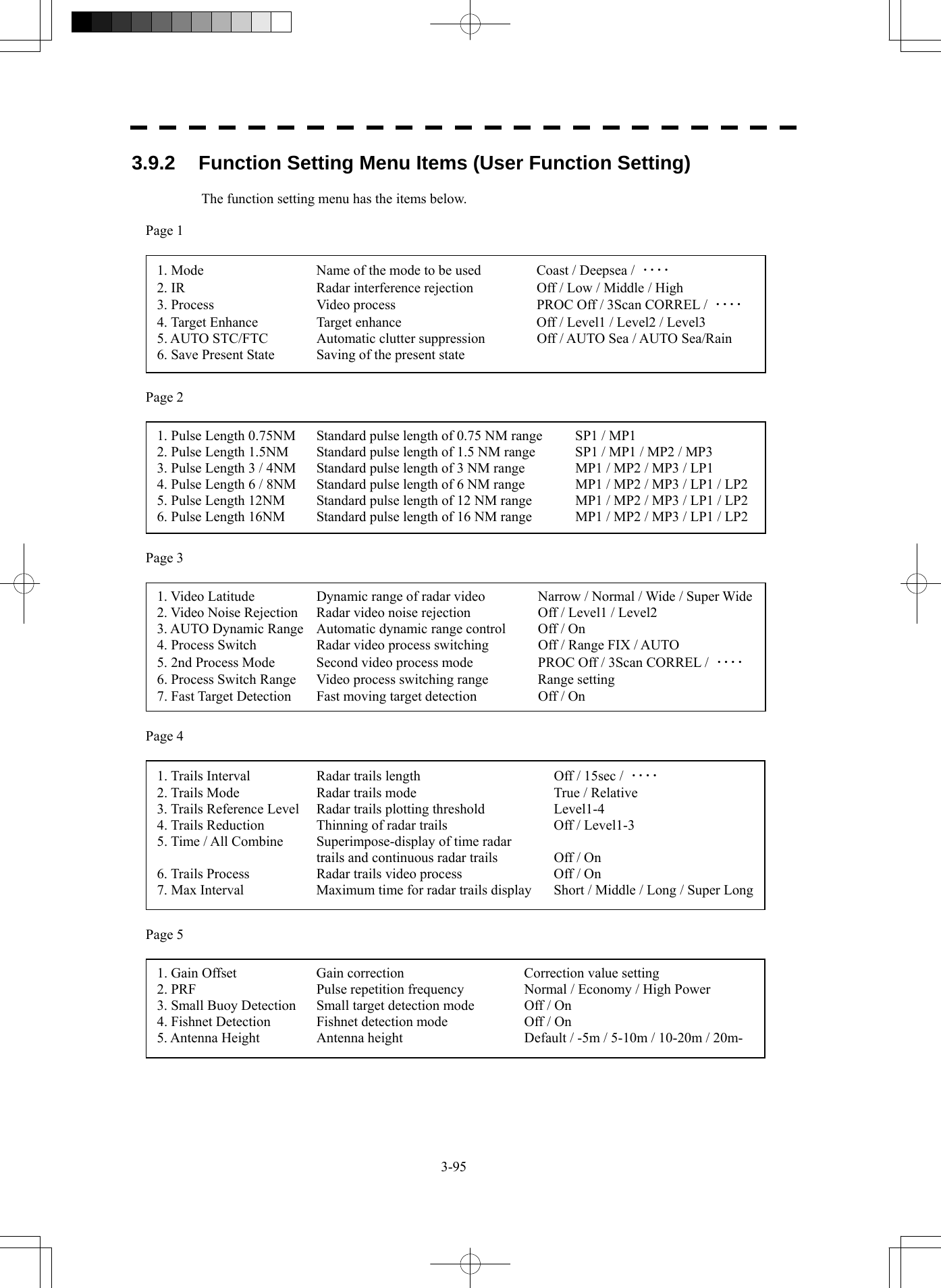
![3-96 3.9 Use Function Key yy y3 3.9.3 Overview of Function Operations (User Function Setting) The following outlines the operation of each function selected from the function setting menu. Procedures 1 Press the [FUNC] key for 2 seconds. The User Function Setting menu will appear. Specify the number for the function for which the settings are to be changed. The following are the operation overviews of each function setting item. [Page 1] [1] Mode • Selects the function name to be indicated at the lower left of the display when the function is selected. • When the setting is changed back to the factory setting, the initial value of the selected mode is called. • The following 11 modes are provided. Coast : Use this mode to monitor a relatively short range, for example, bays and coasts where many boats and ships are running. (Importance is attached to resolution.) Deepsea : Use this mode to monitor a relatively long range. (Importance is attached to long-range gain.) Fishnet : Use this mode to detect small targets hidden by sea clutter returns. (Importance is attached to sea clutter suppression, and gain to moving targets lowers.) Storm : Use this mode when many rain / snow clutter returns or sea clutter returns are detected in stormy weather. (Importance is attached to rain / snow clutter and sea clutter suppression, and gain slightly lowers.) Calm : Use this mode when only a few rain / snow clutter returns or sea clutter returns are detected. Rain : Use this mode when sea clutter is not strong but rain / snow clutter is strong. (Importance is attached to rain / snow clutter suppression, and gain slightly lowers.) Bird : Use this mode to detect flocks of sea birds. Long : Use this mode to monitor utmost distances in the broad ocean. Buoy : Use this mode to detect small targets like radio buoys in areas outside the sea clutter area. (This mode displays targets of which detection probability is low.) User1 : General mode used when the nine modes above are not applicable. User2 : General mode used when the nine modes above are not applicable. [Page 1] [2] IR (Interference Rejection) • Same function as IR described in Section 3.4.1.](https://usermanual.wiki/Japan-Radio/NKE2254.Users-Manual/User-Guide-1510215-Page-191.png)
![3-97 [Page 1] [3] Process (Video Process) • Same function as Process described in Section 3.4.4. [Page 1] [4] Target Enhance • Same function as Target Enhance described in Section 3.4.3. [Page 1] [5] Auto STC / FTC (Auto Sea / Rain) • Detects unwanted waves such as rain / snow clutter and sea clutter and automatically suppresses them. • When the sea state or weather changes, this function automatically performs suppression processing in accordance with the situation. • Suppression processing is not full automatic, and requires the operator to adjust the afterimages of unwanted waves. • To adjust the afterimage of sea clutter, use the [SEA] dial. • To adjust the afterimage of rain / snow clutter, use the [RAIN] dial. • In areas where the density of unwanted waves is low, unwanted waves may remain being judged as targets. Thus, use the automatic clutter suppression mode together with the video process mode. • Characteristics of the automatic clutter suppression function. Off : Disables the automatic clutter suppression function. Select off when rain / snow clutter and sea clutter are not strong. AUTO Sea : Automatically detects the strength of sea clutter, and performs the most suitable sea clutter suppression processing. Even when the strength of sea clutter varies depending on the wind direction, AUTO Sea performs the most suitable suppression processing. Land like islands can be displayed naturally. Since rain clouds outside sea clutter areas are recognized as land, there is no effect of suppressing rain / snow clutter. AUTO Sea/Rain : Along with AUTO Sea, AUTO Rain automatically detects the strength of rain / snow clutter, and performs the most suitable rain / snow clutter suppression processing. When rain clouds are scattered about, AUTO Rain performs rain / snow clutter suppression processing for only the rain-cloud areas. Since land is recognized as rain clouds, land videos become obscure. [Page 2] [1] - [7] Pulse Length • Sets the standard transmitter pulse length in each range. • When the range is called, the pulse range is used. [Page 3] [1] - [7] Process Setting • Operation is the same as that of the Process Setting menu described in Section 3.8.1.](https://usermanual.wiki/Japan-Radio/NKE2254.Users-Manual/User-Guide-1510215-Page-192.png)
![3-98 3.9 Use Function Key yy y3 [Page 4] [1] - [7] Trails Setting • Same functions as in the Trails Setting menu described in Section 3.8.2. [Page 5] [1] Gain Offset • Corrects gain while the function mode is called. • Since the displayed noise level varies depending on the combination of the video process mode and the interference rejection level, gain needs fine adjustment for always obtaining the highest level. • The gain correction function saves the correction value set by the gain adjust in each function mode, so it can obtain the highest gain without the gain adjust being operated when the function mode is changed. • To set high gain, set a value on the “+” side. • To set low gain, set a value on the “-” side. • When the radar interference rejection level is increased, the noise level is lowered. Thus, set a gain correction value to the “+” side. • When the video process mode 3Scan CORREL , 4Scan CORREL , or 5Scan CORREL is used, the noise level is lowered. Thus, set a gain correction value to the “+” side. • When the video process mode Remain or Peak Hold is used, noise is hard to disappear. Thus, set a gain correction value to the “-” side. [Page 5] [2] PRF • Same function as in the Pulse Repetition Frequency described in 3.8.3. [Page 5] [3] Small Buoy Detection • When the automatic sea clutter suppression function is used, this mode is used to process signals for detecting small targets. Off : Activates the general signal processing mode. On : The signal processing mode for detecting small targets. [Page 5] [4] Fishnet Detection • Use this mode to detect small targets hidden by sea clutter returns. • The simultaneous use with the automatic rain / snow clutter suppression function will increase effects. Off : Activates the general signal processing mode. On : Activates the fishnet detection mode. [Page 5] [5] Antenna Height • Set the height of radar antenna above sea level. • The STC/FTC curve is changed. -5m : Set the antenna height under 5m. 5-10m : Set the antenna height 5m to 10m. 10-20m : Set the antenna height 10m to 20m. 20m- : Set the antenna height over 20m.](https://usermanual.wiki/Japan-Radio/NKE2254.Users-Manual/User-Guide-1510215-Page-193.png)
![3-99 3.9.4 Overview of saved Function Setting Data The overview of saved function setting data is as follows: • Factory-set data : Saved data that general operation cannot change • Default data : Standard data of each function mode that users can change • Data that can be called : Saved data that can be called by pressing the [FUNC] key User Function Menu [Page 1] [1] Mode • Calls the default value of the mode, and saves it for the function number. User Function Menu [Page 1] [6] Save Present State • The currently operating state can be saved for the function number. • Use this function to save the state of good setting that will be frequently used. User Function Menu [Page 5] [8] Set Mode Default • Saves the setting of the current function number, as the default setting of the mode. User Function Menu [Page 5] [9] Initialize • Changes the memory contents of the mode, which is used with the current function number, back to the factory setting. Coast Deepsea Fishnet Storm Calm Rain Bird Long Buoy User1 User2 Coast Deepsea Fishnet Storm Calm Rain Bird Long Buoy User1 User2 FUNC1 FUNC2 FUNC3 FUNC4 Present [page5]-[9] [page1]-[1][page5]-[8] [FUNC] [page1]-[6] Function Setting Factory-set data Function Setting Default data Function Setting Data that can be called Current data](https://usermanual.wiki/Japan-Radio/NKE2254.Users-Manual/User-Guide-1510215-Page-194.png)
![3-100 3.10 Use User Setting yy y3 3.10 USE USER SETTING The operation status of the radar is recorded. If the system is operated by more than one operator, the operators can register operation status as suitable for them and call the status. Operation status for up to five operations can be registered, and a name can be assigned to each status. (Up to 10 alphanumeric characters) * Data saved by the user setting • Display Color Setting menu • Buzzer Volume • User Key Setting menu • Display Style (Date display style) • EBL / VRM Control CURS • Cursor Length 3.10.1 Save Operating State (Save User Setting) The system's current operating state can be saved in the system by performing the operation below. Procedures 1 Press the [RADAR MENU] key twice. 2 Open the User Setting menu by performing the following menu operation. 5. Sub Menu → 3. User Setting 3 Press the [2] key. The Input File Name menu will appear. 4 Enter the file name to be saved. The operating state data will be saved. Up to 10 characters can be entered. For the input method on the character input screen, see Section 3.3.4.](https://usermanual.wiki/Japan-Radio/NKE2254.Users-Manual/User-Guide-1510215-Page-195.png)
![3-101 3.10.2 Load Operating State (Load User Setting) The operating state saved in the system can be loaded by performing the operation below. When the operating state is loaded, the previous operating state data is discarded. Therefore, if you do not want to discard the operating state data, save the operating state by performing the operation described in Section 3.10.1. Procedures 1 Put the cursor on the display item switching (Brilliance / Alarm ① on page 2-28), and press the [ENT] key. The Brilliance menu and the Display INFO menu are switched. 2 Put the cursor on the user setting load (Display information ⑦ on page 2-28), and press the [ENT] key. The Load User Setting menu will appear. 3 Press numeric keys corresponding to the file to be loaded. Confirmation Window will appear. 4 Press the [1] key. The operating state data will be loaded. 3.10.3 Delete Operating State (Delete User Setting) The operating state saved in the system can be deleted by performing the operation below. Use this function to delete unnecessary operating state data. Procedures 1 Press the [RADAR MENU] key twice. 2 Open the Delete User Setting menu by performing the following menu operation. 5. Sub Menu → 3. User Setting → 3. Delete User Setting 3 Press numeric keys corresponding to the file to be deleted. Confirmation Window will appear. 4 Press the [1] key. The operating state data will be deleted.](https://usermanual.wiki/Japan-Radio/NKE2254.Users-Manual/User-Guide-1510215-Page-196.png)
![3-102 3.11 Using Card yy y3 3.11 USING CARD This radar has two card slots. Inserting a flash memory card (option) into a card slot, you can save the following contents, saved in the process unit, in the card or can load data from the card to the process unit. • Trails of own ship : 7000 points maximum (Not used on the JPL-600-MK2 for VTS) • Track of other ship : 20 target×1500 points (the Target Tracking unit, or AIS unit option is necessary) • Mark Line : 2000 points maximum (20000 items when the plotter unit option is connected) • Waypoint : 999 points maximum (the plotter unit option is necessary) • Route : 10 routes maximum (the plotter unit option is necessary) These pieces of information can be saved in a flash memory card as a file. The internal capacity is as large as only a file. An internally created file can be saved until the flash memory card is full. 3.11.1 Operate File on the Card (File Manager) Procedures 1 Insert a flash memory card into the card slot. Flash memory card (option) is necessary. For the insertion and removal of the card, see HOW TO INSERT AND REMOVE A CARD in the appendix. 2 Press the [STBY] key. The transmission standby state is activated. 3 Press the [RADAR MENU] key twice. 4 Press the [1] key. The File Manager window will appear. The window will not be open when the system is in the transmission state.](https://usermanual.wiki/Japan-Radio/NKE2254.Users-Manual/User-Guide-1510215-Page-197.png)
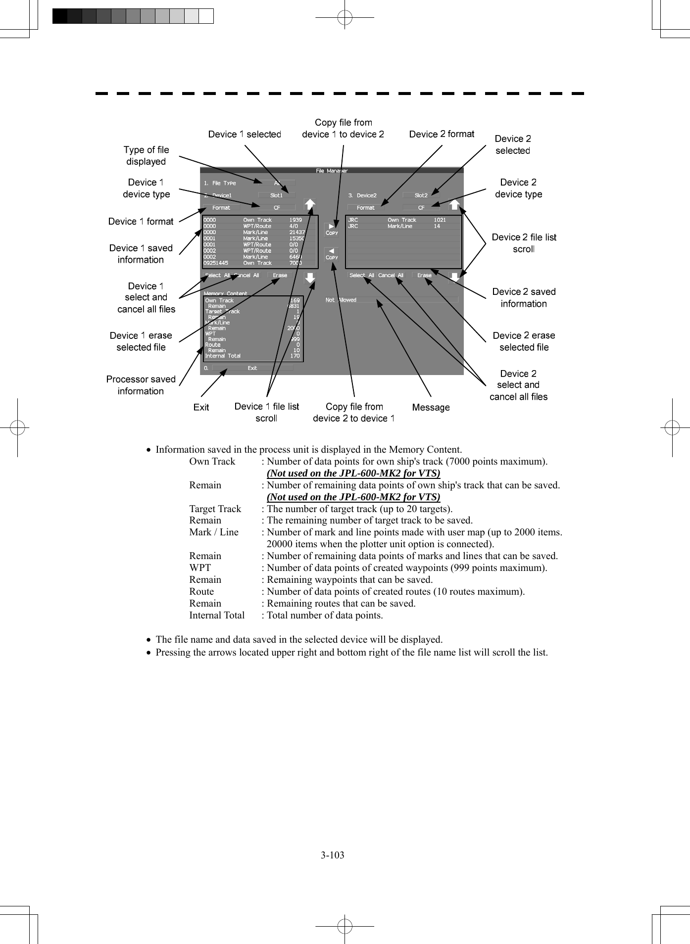
![3-104 3.11 Using Card yy y3 [I] Copy Internal Information to Card (Copy Internal -> Card) Procedures 1 Press the [2] key while the File Manager menu is open. Selected items for Device1 will be displayed. 2 Press the [1] key. Internal is selected. 3 Press the [3] key. Selected items for Device2 will be displayed. 4 Press numeric keys corresponding to the device to which data is to be copied. The list of files saved in the selected device will be displayed. 5 Put the cursor on the data to be copied, and press the [ENT] key. Pressing the [ENT] key will select the data. Pressing the [ENT] key one more time will cancel the selection. 6 Put the cursor on Copy , and press the [ENT] key. The character input screen for the Input File Name menu will appear. 7 Enter the file name to be saved. Up to 10 characters can be entered. For the input method on the character input screen, see Section 3.3.4. After the data has been entered, Confirmation Window will appear. 8 Press the [1] key. The entered name is written into the selected device as a file name. Up to the maximum number of items, described on the previous page, can be saved in the device. With regard to the capacity for saving data, data can be saved on a flash memory card as a file, and those files can be saved until the flash memory card is full.](https://usermanual.wiki/Japan-Radio/NKE2254.Users-Manual/User-Guide-1510215-Page-199.png)
![3-105 [II] Load Information from Card to Internal Portion (Copy Card -> Internal) Procedures 1 Press the [2] key while the File Manager menu is open. Selected items for Device1 will be displayed. 2 Press the [1] key. Internal is selected. 3 Press the [3] key. Selected items for Device2 will be displayed. 4 Press numeric keys corresponding to the device in which data to be loaded is saved. The list of files saved in the selected device will be displayed. 5 Put the cursor on the data to be copied, and press the [ENT] key. Pressing the [ENT] key will select the data. Pressing the [ENT] key one more time will cancel the selection. 6 Put the cursor on Copy , and press the [ENT] key. Confirmation Window will appear. 7 Press the [1] key to overwrite data, or press the [2] key to add new data. When Overwrite is selected, internally saved data is deleted and new data is loaded. When Add is selected, new data is added to the saved data. 8 Press the [1] key. The selected file is loaded into the system from the card. When adding data saved on the card to the data saved in the system, data can be copied from multiple files. However, when the maximum number of units of data is reached, additional data cannot be loaded. Even in the ADD mode, WPT data and Route data are overwritten.](https://usermanual.wiki/Japan-Radio/NKE2254.Users-Manual/User-Guide-1510215-Page-200.png)
![3-106 3.11 Using Card yy y3 [III] Copy Information (Copy) Procedures 1 Press the [2] key while the File Manager menu is open. Selected items for Device1 will be displayed. 2 Press numeric keys corresponding to the device from which data is to be copied. The list of files saved in the selected device will be displayed. 3 Press the [3] key. Selected items for Device2 will be displayed. 4 Press numeric keys corresponding to the device to which data is to be copied. The list of files saved in the selected device will be displayed. 5 Put the cursor on the data to be copied, and press the [ENT] key. Pressing the [ENT] key will select the data. Pressing the [ENT] key one more time will cancel the selection. 6 Put the cursor on Copy , and press the [ENT] key. The character input screen for the Input File Name menu will appear. If there is a file having the same name, the file selection window will appear. When deleting saved data and copying new data, press the [1] key to select Overwrite. When adding data to a Waypoint file, press the [2] key to select Add. Even in the Add mode, WPT data and Route data are overwritten. When selection has been made, Confirmation Window will appear. 7 Enter the file name to be saved. Up to 10 characters can be entered. For the input method on the character input screen, see Section 3.3.4. After the data has been entered, Confirmation Window will appear. 8 Press the [1] key. The entered name is written into the selected device as a file name.](https://usermanual.wiki/Japan-Radio/NKE2254.Users-Manual/User-Guide-1510215-Page-201.png)
![3-107 [IV] Erase File (Erase) Procedures 1 Press the [2] key while the File Manager menu is open. Selected items for Device1 will be displayed. 2 Press numeric keys corresponding to the device in which data to be erased is saved. The list of files saved in the selected device will be displayed. 3 Select data to be erased. Pressing the [ENT] key will select the data. Pressing the [ENT] key one more time will cancel the selection. 4 Put the cursor on Erase , and press the [ENT] key. Confirmation Window will appear. 5 Press the [1] key. The selected file will be erased. [V] Initializing a card (Format) Procedures 1 Press the [2] or [3] key while the File Manager is open. Selected items for Device1 or Device2 will be displayed. 2 Put the cursor on Format for the device to be initialized, and press the [ENT] key. Confirmation Window will appear. 3 Press the [1] key. Initialization will be executed. [VI] Showing data saved on the card (Show Card) Procedures 1 Press the [2] or [3] key while the File Manager is open. Selected items for Device1 or Device2 will be displayed. 2 Press numeric keys corresponding to the device in which data to be displayed is saved. The list of files saved in the selected device will be displayed. [VII] Exit Exit 1 Press the [0] key. The File Manager menu will close.](https://usermanual.wiki/Japan-Radio/NKE2254.Users-Manual/User-Guide-1510215-Page-202.png)
![3-108 3 3.12 Display Simple Chart yy y3.12 DISPLAY SIMPLE CHART 3.12.1 Display JRC Coastline ROM Card [MAP] z Insert the JRC coastline ROM card with the top surface upward into card slot 1 (lower) or 2 (upper). Press the [MAP] key, and the coastlines will be displayed automatically. z Two JRC coastline ROM cards can be inserted into card slots 1 and 2 at the same time. z For ranges including detailed coastlines, refer to the Coastline ROM card catalog. z Do not insert an ERC card (provided by Japan Hydrographic Association) or C-MAP card into a card slot while JRC Coastline ROM card is in the other slot. Doing so causes display trouble. Procedures 1 Press the [Map] key while the JRC coastline ROM card is being inserted into the card slot. Coastline will be displayed. For the insertion and removal of the card, see HOW TO INSERT AND REMOVE A CARD in the appendix. 3.12.2 Display ERC Card [MAP] z Insert the ERC card (provided by Japan Hydrographic Association) with the top surface upward into card slot 1 (lower) or 2 (upper). Press the [MAP] key, and the coastlines will be displayed automatically. z Two ERC cards can be inserted into card slots 1 and 2 at the same time. z For ranges of charts to be displayed, refer to the catalog issued by Japan Hydrographic Association. z Do not insert JRC Coastline ROM card or C-MAP card into a card slot while the ERC card is in the other slot. Doing so causes display trouble. Procedures 1 Press the [Map] key while the ERC card is being inserted into the card slot. Coastlines will be displayed. For the insertion and removal of the card, see HOW TO INSERT AND REMOVE A CARD in the appendix.](https://usermanual.wiki/Japan-Radio/NKE2254.Users-Manual/User-Guide-1510215-Page-203.png)
![3-109 3.12.3 Display JRC Chart on CF Card (SEL JRC ROM Card File) By copying multiple JRC coastline ROM cards onto a compact flash memory card, this function selectively displays any two charts among the copied charts. For a ship that sails in the wide range, this function is convenient because charts can be selected from the menu without alternately inserting JRC coastline ROM cards. Note: The copied chart can operate only in the system that originally copied the chart. The copied chart cannot be operated in other systems. The capacity of the compact flash memory card to be used is 2GB or less. [I] Copying a JRC ROM card to a CF card (Copy JRC ROM Card to CF) Procedures 1 Insert a JRC coastline ROM card into card slot 1 (lower) and insert a compact flash memory card into card slot 2 (upper). Flash memory card (option) is necessary. A PCMCIA (PC card) adapter for the compact flash memory card is necessary to insert a compact flash memory card. For the insertion and removal of the card, see HOW TO INSERT AND REMOVE A CARD in the appendix. 2 Press the [Map] key for 2 seconds. The Map Setting menu will appear. 3 Open the JRC / ERC Setting menu by performing the following menu operation. 3. JRC/ERC Setting → 9. Next 4 Press the [7] key. Confirmation Window will appear. 5 Press the [1] key. Data on the JRC card will be copied onto the compact flash memory card. 6 To copy multiple JRC charts, alternately change JRC coastline ROM cards and repeat procedures 4 and 5.](https://usermanual.wiki/Japan-Radio/NKE2254.Users-Manual/User-Guide-1510215-Page-204.png)
![3-110 3 3.12 Display Simple Chart yy y[II] Selecting a copied JRC chart (SEL JRC ROM Card File) Procedures 1 Insert a compact flash memory card on which a JRC chart has been copied into slot 2. Flash memory card (option) is necessary. For the insertion and removal of the card, see HOW TO INSERT AND REMOVE A CARD in the appendix. 2 Press the [Map] key for 2 seconds. The Map Setting menu will appear. 3 Press the [6] key. The SEL JRC ROM Card File menu will appear. 4 Press numeric keys corresponding to the desired file to be selected. The selected file will be shown in reverse video. Cancelling the selected file 5 Press numeric keys corresponding to the file to be cancelled. The canceled file name will return to the original normal display. Note: Up to 2 files of the JRC chart can be selected. If JRC charts are not copied on the compact flash memory card, the file names is not be displayed. 3.12.4 Fill Charts (Fill Land Area) This function fills the chart when JRC / ERC card is in use. Procedures 1 Press the [Map] key for 2 seconds. The Map Setting menu will appear. 2 Press the [1] key. The Fill Land Area function is switched between on and off. On : Charts are filled. Off : Charts are not filled.](https://usermanual.wiki/Japan-Radio/NKE2254.Users-Manual/User-Guide-1510215-Page-205.png)
![3-111 3.12.5 Set JRC / ERC Chart Display (JRC / ERC Setting) This function enables the setting of detail information about chart display. Procedures 1 Press the [Map] key for 2 seconds. The Map Setting menu will appear. 2 Press the [3] key. The JRC / ERC Setting Menu will appear. Detail information about the colors and brilliance of JRC / ERC chart display can be set by changing the settings of the menu items. The data of colors and brilliance can be saved for each day / night mode. [1] Day/Night • Select a desired display mode before setting the colors and brilliance of chart display. • There are 5 selection items: Day1 , Day2 , Day3 , Dusk , and Night . [2] Color of Land • Select the color of land display. • There are 4 selection items: Brown , Yellow , Green , and White . [3] Bright of Land • Select the brilliance of land display. • There are 3 selection items: Low , Middle , and High . [4] Color of Sea • Select the color of sea display. • There are 4 selection items: Gray , Gray , Blue , and Green . [5] Bright of Sea • Select the bright of sea display. • There are 4 selection items: Off , Low , Middle , and High . [6] Color of Name • Select the color of a location name. • There are 8 selection items: Black , White , Gray , Blue , Green , Yellow , Pink , and Red .](https://usermanual.wiki/Japan-Radio/NKE2254.Users-Manual/User-Guide-1510215-Page-206.png)
![3-112 3 3.12 Display Simple Chart yy y[7] Bright of Name • Select the brilliance of location name display. • There are 4 selection items: Off , Low , Middle , and High . [8] Bright of Track/Mark/Line • Select the brilliance of track, mark and line. • There are 4 selection items: Level1 , Level2 , Level3 , and Level4 . [9] Next • Moves to the next page. [1] LAT/LON Line • Select the mode to display latitude and longitude lines. • There are 2 selection items: Line&NUM :Displays both latitude / longitude lines and values indicating the latitude and longitude. NUM :Displays only the values indicating the latitude and longitude. [2] Color of L/L Line • Select the colors that are to represent latitude and longitude lines. • There are 8 selection items: Black , White , Gray , Blue , Green , Yellow , Pink , and Red . [3] Bright of L/L Line • Select the bright of latitude / longitude line display. • There are 4 selection items: Off , Low , Middle , and High . [4] ERC Display Request • Set whether to display data saved in the ERC. On : Data in the ERC is displayed. Off : Data in the ERC is not displayed. [5] ERC Mark • Select the size of mark display on the ERC chart. Normal : The ERC mark is displayed in normal size. Small : The ERC mark is displayed in a size smaller than normal.](https://usermanual.wiki/Japan-Radio/NKE2254.Users-Manual/User-Guide-1510215-Page-207.png)
![3-113 [6] JRC ROM Card Display • Sets the display contents of the JRC card. • The JRC ROM Card Display menu will appear. [1] Light House • Determine whether to display lighthouses. • Set whether to display data saved in the ERC. On : Light houses are displayed. Off : Light houses are not displayed. [2] Buoy • Determine whether to display buoys. • Set whether to display data saved in the ERC. On : Buoys are displayed. Off : Buoys are not displayed. [3] Rough Line • Determine whether to display rough lines. • Set whether to display data saved in the ERC. On : Rough lines are displayed. Off : Rough lines are not displayed. [4] Other Line • Determine whether to display other lines. • Set whether to display data saved in the ERC. On : Other lines are displayed. Off : Other lines are not displayed.](https://usermanual.wiki/Japan-Radio/NKE2254.Users-Manual/User-Guide-1510215-Page-208.png)
![3-114 3 3.12 Display Simple Chart yy ySetting Contour Lines on JRC Chart (Contour Setting) Procedures 1 Press the [Map] key for 2 seconds. The Map Setting menu will appear. 2 Press the [4] key. The Contour Setting Menu will appear. Depths and display colors can be set for 9 contour lines in total: 8 for depth specification and 1 for other depths. 3 Press numeric keys corresponding to the depth for which the settings are to be changed. The numeric value input screen for the Contour Setting menu will appear. 4 Enter the depth to be set. For how to input numeric data on the numeric value input screen, see Section 3.3.4. After a value has been entered, depth contour setting items will be displayed. 5 Press numeric keys corresponding to the type of the depth contour to be set. The type of line for displaying the depth contour corresponding to the depth is set. 6 Select the number of display color to be set, pressing the numeric key. The selected color to represent the contour lines of the depth will be set. When Off is selected, the depth contour will not be displayed. To change the settings of other depths, repeat steps 3 to 6. JRC ROM card plotting mode (JRC ROM Card Draw Mode) Procedures 1 Press the [Map] key for 2 seconds. The Map Setting menu will appear. 2 Press the [8] key. The JRC ROM Card Draw Modes are switched. If the chart is plotted in segments due to the [Fast] display mode, change the mode to the [Detailed] mode. Fast : The chart is displayed quickly. Detailed : The chart is displayed in detail.](https://usermanual.wiki/Japan-Radio/NKE2254.Users-Manual/User-Guide-1510215-Page-209.png)
![3-115 3.12.6 Display C-MAP Card [MAP] • Turn off the power supply to the system, insert a C-MAP card into either card slot 1 (lower) or card slot 2 (upper), and then press the [Map] key. Coastlines will be displayed. • Be sure to turn off the power supply to the system before inserting or removing a C-MAP card. If a C-MAP card is inserted or removed with the power supply turned on, a malfunction will occur on the display. • When using a compact flash memory type C-MAP card, be sure to use a PCMCIA(PC card) adapter for the compact flash memory card which is commonly sold at retail outlets. • Only one C-MAP card can be inserted. If two C-MAP cards are inserted at the same time, a malfunction will occur on the display. • With regard to the range of the chart to be displayed, refer to the catalog. • Do not simultaneously insert a JRC coastline ROM card and an ERC card (issued by Japan Hydrographic Association) into the card slot. A malfunction will occur on the display. Procedures 1 Press the [Map] key while a C-MAP card is being inserted into the card slot. Coastlines will be displayed. For the insertion and removal of the card, see HOW TO INSERT AND REMOVE A CARD in the appendix. Insert or remove a C-MAP card while the power supply to the system is turned off. C-MAP display setting (C-MAP Setting) Procedures 1 Press the [Map] key for 2 seconds. The Map Setting menu will appear. 2 Press the [2] key. The C-Map Setting menu will appear. [1] LAT/LON Line Display • Set whether to display latitude / longitude lines on the C-MAP. On : Latitude / longitude lines are displayed. Off : Latitude / longitude lines are not displayed. [2] Depth Display • Set whether to display water depth values on the C-MAP On : Water depth values are displayed. Off : Water depth values are not displayed.](https://usermanual.wiki/Japan-Radio/NKE2254.Users-Manual/User-Guide-1510215-Page-210.png)
![3-116 3 3.12 Display Simple Chart yy y[3] Depth Unit • Set the unit to display water depth value on the C-MAP. Feet : The feet is used as the unit of water depth. Fathom : The fathom is used as the unit of water depth. Meters : The meter is used as the unit of water depth. Decimal Fathom : The decimal fathom is used as the unit of water depth. [4] Light Sectors Display • Set whether to display lighthouse's light sectors on the C-MAP. On : Light sectors are displayed. Off : Light sectors are not displayed. [5] Light Sectors Level • Set the level of lighthouse's light sectors displayed on the C-MAP. Levels from A to H are available. [6] Chart Boundary • Set whether to display chart boundary on the C-MAP. On : The chart boundary is displayed. Off : The chart boundary is not displayed. [7] Buoy&Beacon • Set the buoy and beacon display on the C-MAP and the type of marks. Off : Buoys and beacons are not displayed. International : Buoys and beacons are displayed in the international format. US : Buoys and beacons are displayed in the US format. Simple : Buoys and beacons are displayed in a simple format. [8] Names • Set whether to display place-names on the C-MAP. On : Place-names are displayed. Off : Place-names are not displayed. [9] Next • Move on to the following page. [1] Land Marks • Set whether to display land marks on the C-MAP. On : Land marks are displayed. Off : Land marks are not displayed.](https://usermanual.wiki/Japan-Radio/NKE2254.Users-Manual/User-Guide-1510215-Page-211.png)
![3-117 [2] River&Lake • Set whether to display rivers and lakes on the C-MAP. On : Rivers and lakes are displayed. Off : Rivers and lakes are not displayed. [3] Cultural • Set whether to display cultural facilities on the C-MAP. On : Cultural facilities are displayed. Off : Cultural facilities are not displayed. [4] Bottom Type • Set whether to display bottom sediment on the C-MAP. On : Bottom sediment is displayed. Off : Bottom sediment is not displayed. [5] Under Water • Set whether to display reefs on the C-MAP. On : Reefs are displayed. Off : Reefs are not displayed. [6] Depth Contour • Set whether to display depth contour on the C-MAP. On : Depth contour is displayed. Off : Depth contour is not displayed.](https://usermanual.wiki/Japan-Radio/NKE2254.Users-Manual/User-Guide-1510215-Page-212.png)
![3-118 3 3.12 Display Simple Chart yy y3.12.7 Correcting Chart Position (Map Display Setting) Procedures 1 Press the [Map] key for 2 seconds. The Map Setting menu will appear. 2 Press the [5] key. The Map Display Setting Menu will appear. There are three methods for correcting the chart position. [1] Shift Coast Line 1 With regard to display Coast Line 1, set the correction value by operating the cursor. Procedures 1 Press the [1] key while the Map Display Setting Menu is open. The chart display position correction 1 (Shift Coast Line 1) is set. 2 Move the cursor to the chart on which a position is to be corrected, and Press the [ENT] key. 3 Move the cursor to the radar video of which position is to be corrected, and Press the [ENT] key. Setting (correcting) will be indicated for Shift Coast Line 1. At this time, Map Shift is displayed in the map position correction (lower right of the display on page 2-4), indicating that the position is being corrected. Note: A correction value can be operated in the range -9.999’ to +9.999’. Cancellation 1 Press the [1] key while the Map Display Setting menu is open. Delete (no correction) is selected for the Shift Coast Line 1. At this time, Map Shift is not displayed in the map position correction (lower right of the display on page 2-4).](https://usermanual.wiki/Japan-Radio/NKE2254.Users-Manual/User-Guide-1510215-Page-213.png)
![3-119 [2] Shift Coast Line 2 With regard to Shift Coast Line 2, enter latitude / longitude to set a correction value. A correction value can be entered in the range -9.999’ to +9.999’. Procedures 1 Press the [2] key while the Map Display Setting Menu is open. The latitude / longitude input screen for the Shift Coast Line2 menu will appear. 2 Enter a latitude / longitude correction value. For how to enter a value on the latitude / longitude input screen, see Section 3.3.4. The latitude / longitude correction value is determined. At this time, Map Shift is displayed in the map position correction (lower right of the display on page 2-4), indicating that the position is being corrected. Cancellation 1 Press the [2] key while the Map Display Setting menu is open. The latitude / longitude input screen for the Shift Coast Line2 menu will appear. 2 Press the [0] key, and then [ENT] key. The correction value for the latitudinal direction will be set to 0. 3 Press the [0] key, and then [ENT] key. The correction value for the longitudinal direction will be set to 0. At this time, Map Shift is not displayed in the map position correction (lower right of the display on page 2-4). [3] LAT/LON Correction This method corrects a chart position by changing the values of latitude and longitude that are sent by the navigation equipment. Only our service engineers are to use this correction method because the contents of data such as track data to be saved are changed when the method is used. A correction value can be entered in the range -9.999’ to +9.999’. Procedures 1 Press the [3] key while the MAP Display Setting Menu is open. The latitude / longitude input screen for the LAT/LON Correction menu will appear. 2 Enter a latitude / longitude correction value. For how to enter a value on the latitude / longitude input screen, see Section 3.3.4. The latitude / longitude correction value is determined. Cancellation 1 Press the [3] key while the Map Display Setting menu is open. The latitude / longitude input screen for the LAT/LON Correction menu will appear. 2 Press the [0] key, and then [ENT] key. The correction value for the latitudinal direction will be set to 0.](https://usermanual.wiki/Japan-Radio/NKE2254.Users-Manual/User-Guide-1510215-Page-214.png)
![3-120 3 3.12 Display Simple Chart yy y3 Press the [0] key, and then [ENT] key. The correction value for the longitudinal direction will be set to 0. [4] Map Center Position This method corrects a chart position by entering the values of latitude and longitude at radar station position in manual mode. If latitude and longitude data sent by the navigation equipment has been entered, the data has priority over the manually entered values. Procedures 1 Press the [4] while the Map Display Setting Menu is open. The latitude / longitude input screen for the Map Center Position menu will appear. 2 Enter a latitude / longitude value. For how to enter a value on the latitude / longitude input screen, see Section 3.3.4. The latitude / longitude correction value is determined. Cancellation 1 Press the [4] key while the Map Display Setting menu is open. The latitude / longitude input screen for the Map Center Position menu will appear. 2 Press the [0] key, and then press the [ENT] key. The latitude direction correction value will set at 0. 3 Press the [0] key, and then press the [ENT] key. The longitude direction correction value will be set at 0. 3.12.8 Chart plotting bearing mode (Map Draw AZI Mode) Procedures 1 Press the [Map] key for 2 seconds. The Map Setting menu will appear. 2 Press the [7] key. The Map Draw AZI Mode are switched. N-Up : The chart is displayed in the North-up mode. C-Up : The chart is displayed in the Course-up mode.](https://usermanual.wiki/Japan-Radio/NKE2254.Users-Manual/User-Guide-1510215-Page-215.png)
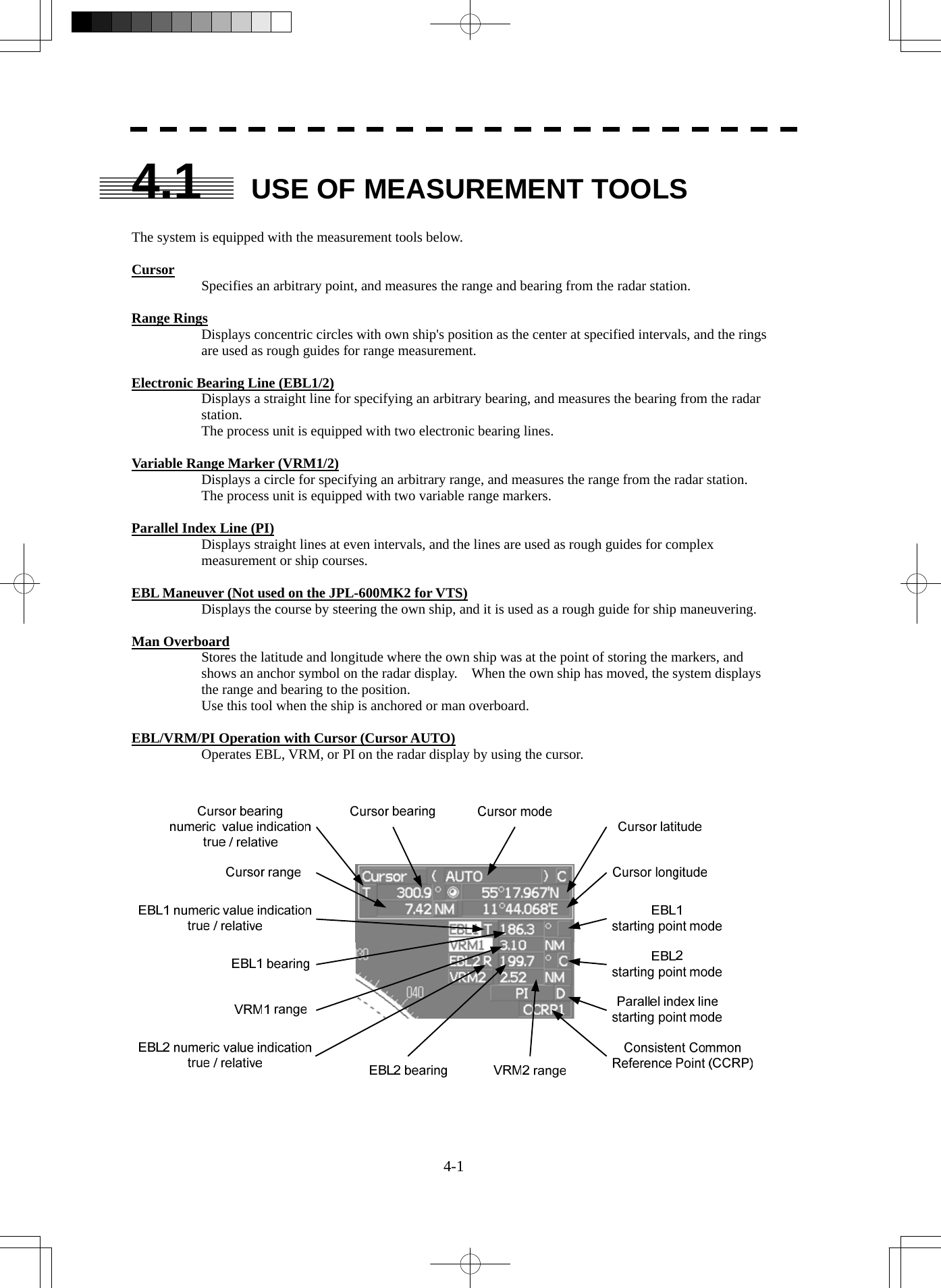
![4-2 4.1 Use of Navigation Tools yyyy4 4.1.1 Using Cursor (Cursor) Procedures 1 Move the cursor onto the PPI display by moving the trackball. When the cursor is moved onto the PPI display, the arrow cursor turns into a cross cursor. 4.1.2 Using Range Rings [RR / HL] Procedures 1 Press the [RR / HL] key. The range ring display switches disappear and appear between display and non-display each time the [RR / HL] key is pressed. The range ring interval is shown in the Range Rings display on / off (upper left of the display ② on page 2-16). The range between the target and own ship can be determined by visually measuring the target's position that lies between two range rings. For change of the brilliance of range rings, refer to Section 3.8.6.](https://usermanual.wiki/Japan-Radio/NKE2254.Users-Manual/User-Guide-1510215-Page-219.png)
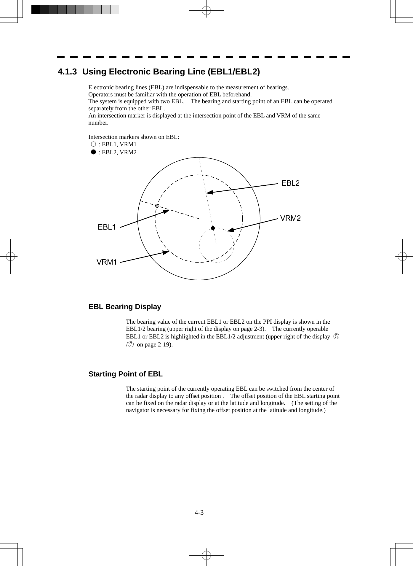
![4-4 4.1 Use of Navigation Tools yyyy4 [I] Operating EBL (EBL) To operate EBL Procedures 1 Press the [EBL1] or [EBL2] key. The EBL adjustment (upper right of the display ⑤/⑦ on page 2-19) will be highlighted, and the selected EBL becomes operable. 2 Turn the [EBL] dial. To turn the [EBL] dial to the right, turn the EBL control clockwise, to turn the [EBL] dial to the left, turn the EBL control counterclockwise. Cancellation 1 Press the [EBL1] or [EBL2] key again. The selected EBL display will disappear. [II] Moving the Starting Point of EBL The system provides three types of EBL starting points. Select one of them in accordance with purpose. :The EBL starting point is defined as the own ship's position. C :The EBL starting point is moved and fixed on the radar display. D :The EBL starting point is moved and fixed at the latitude and longitude. (The navigator needs to be connected.) To move the starting point of EBL Procedures 1 Make EBL1 or EBL2 operable. 2 Press the [EBL] dial to set C or D for the EBL1 / EBL2 starting point mode switching (upper right of the display ⑪/⑫ on page 2-19). The selected EBL starting point mode is switched as shown below each time the dial is pressed. ⇒ C ⇒ D ⇒ 3 Put the cursor on the EBL starting point is to be moved, and press the [ENT] key. The selected EBL starting point will be determined.](https://usermanual.wiki/Japan-Radio/NKE2254.Users-Manual/User-Guide-1510215-Page-221.png)
![4-5 To return the EBL starting point to radar station position Procedures 1 Make EBL1 or EBL2 operable. 2 Press the [EBL] dial to set for the EBL1 / EBL2 starting point mode switching (upper right of the display ⑪/⑫ on page 2-19). The selected EBL starting point will be set as the radar station display position. [III] Setting EBL Operation Mode To set the numeric value display mode of EBL (EBL Bearing REF) Determine whether to display EBL in true bearing mode or relative bearing mode. (Even if this mode is switched, measured values do not change on the JPL-600MK2.) Procedures 1 Put the cursor on the EBL1/2 numeric value indication true / relative switching (upper right of the display ⑨/⑩ on page 2-19), and press the [ENT] key. The selected mode is switched as shown below each time the [ENT] key is pressed. T ⇒ R ⇒ T T :EBL bearing is displayed in true bearing mode. R :EBL bearing is displayed in relative bearing mode. To set a mode for fixing EBL display (EBL Bearing Fix) (Not used on the JPL-600MK2) When this function is set to Angle , an EBL is fixed to the preset bearing. When the function is set to Screen , the EBL is fixed on the radar display. Procedures 1 Press the [RADAR MENU] key twice. 2 Open the EBL/Cursor Setting menu by performing the following menu operation. 5. Sub Menu 9. EBL/Cursor Setting 3 Press [1] or [2] key. To set EBL1, press the [1] key, to set EBL2, press the [2] key Angle :EBL bearing is fixed to the preset value. Screen :EBL bearing is fixed on the radar display. Note: Course data is necessary for turning on this function.](https://usermanual.wiki/Japan-Radio/NKE2254.Users-Manual/User-Guide-1510215-Page-222.png)
![4-6 4.1 Use of Navigation Tools yyyy4 4.1.4 Using Variable Range Marker (VRM1 / VRM2) Variable range markers (VRM) are indispensable to the measurement of ranges. Operators must be familiar with the operation of VRM beforehand. The system is equipped with two VRM. The VRM can be operated separately from each other. An intersection marker is displayed at the intersection point of the VRM and EBL of the same number. When the starting point of an EBL is offset, the center of the VRM is defined as the offset EBL starting point. Intersection markers shown on VRM: : EBL1, VRM1 : EBL2, VRM2 VRM Operation The range value of the current VRM1 or VRM2 on the PPI display is shown in the VRM1/2 range (upper right of the display on page 2-3). The currently operable VRM1 or VRM2 is highlighted in the VRM1/2 adjustment (upper right of the display ⑥/⑧ on page 2-19). To operate VRM Procedures 1 Press the [VRM1] or [VRM2] key. The VRM adjustment (upper right of the display ⑥/⑧ on page 2-19) will be highlighted, and the selected VRM becomes operable. 2 Turn the [VRM] dial. To turn the [VRM] dial to the right, the VRM control wide, to turn the [VRM] dial to the left, the VRM control narrow. Cancellation 1 Press the [VRM1] or [VRM2] key again. The selected EBL display will disappear.](https://usermanual.wiki/Japan-Radio/NKE2254.Users-Manual/User-Guide-1510215-Page-223.png)
![4-7 4.1.5 Using Parallel Index Lines (PI Menu) Parallel index lines can be displayed. [I] Operating Parallel Index Lines (PI) Procedures 1 Press the [VRM] dial. Parallel index lines and the PI Menu will appear. To change the bearing of parallel index lines, turn the [EBL] dial, to change the line interval, turn the [VRM] dial. The bearing and interval of parallel index lines are displayed in the PI Menu. 2 Press the [VRM] dial again. The parallel index lines will be fixed. Note: Parallel index lines are operable only while the PI Menu is displayed. When the menu is closed, the parallel index line display remains, but the settings of the bearing and interval cannot be adjusted any more. To adjust the bearing and interval after closing the menu, press the [VRM] dial twice to open the PI Menu. Cancellation 1 Press the [VRM] dial again. The parallel index line display will disappear.](https://usermanual.wiki/Japan-Radio/NKE2254.Users-Manual/User-Guide-1510215-Page-224.png)
![4-8 4.1 Use of Navigation Tools yyyy4 [II] Operation of Parallel Index Lines Parallel index lines rotate in the same direction as you turn the [EBL] dial. ( ① , ② ) The intervals of parallel index lines narrow when you turn the [VRM] dial counterclockwise ( ③ ), and widen when you turn the [VRM] dial clockwise ( ④ ). HLEBL1 EBL2 VRM1 VRM2 When the [VRM] dial is pressed, the PI Menu closes and the parallel index lines are fixed. During the operation of parallel index lines, pressing the [EBL1] or [EBL2] key disables operation for rotation directions. Pressing the [VRM1] or [VRM2] key disables operation for parallel index line intervals.](https://usermanual.wiki/Japan-Radio/NKE2254.Users-Manual/User-Guide-1510215-Page-225.png)
![4-9 [III] Settings in PI Menu The operation of parallel index lines can be set in the PI Menu. Procedures 1 Open the PI Menu by performing the following menu operation. Tool 1. PI Menu [1] Display for All Lines Sets the parallel index line display to on or off. On :Parallel index lines are displayed. Off :Parallel index lines are not displayed. [2] Operation Mode Sets an operation mode for parallel index lines. All :All the parallel lines are operated at the same time. Individual :The bearing of each line is operated individually. Track :Equally spaced lateral lines are displayed on both sides. Equiangular :Two lines intersecting at the center of a circle are displayed. All IndividualTrack EquiangularPIPI PIPI](https://usermanual.wiki/Japan-Radio/NKE2254.Users-Manual/User-Guide-1510215-Page-226.png)
![4-10 4.1 Use of Navigation Tools yyyy4 Operation if Individual is selected A line perpendicular to the radar station and the intersection marker "----○" are displayed on an operable line. Turning the [EBL] dial changes the direction. Pressing the [VRM] dial changes the range, end point 1, or end point 2 to be operated. An operable point is displayed with " " and can be operated by turning the [VRM] dial. If Sequential is selected for [3] Control, the parallel index lines of the next number can be displayed by pressing the [EBL] dial. To close the menu, press [0] key. Operation if Equiangular is selected Select a group of lines to be operated according to the setting of [3] Control. Pressing the [EBL] dial switches between the direction change mode and elevation-angle change mode. Turning the [EBL] dial changes the direction or elevation angle. [3] Control Determines whether to operate all the lines at the same time. The setting items are determined by the setting of [2] Operation Mode. If All is selected The setting cannot be changed. All : All the lines are operated at the same time. If Individual is selected Determine whether to set consecutive lines or individual lines. Sequential : Lines are operated sequentially. Index Line1 to Line8 : A specified line is operated. If Track or Equiangular is selected Select a group of lines to be operated. Group1 to Group4 : A specified group is operated. [4] Floating Moves the center point of parallel index lines. Off : The starting point of parallel index lines is defined as the own ship's position. Screen Fix : The center of parallel index lines is moved and fixed on the radar display. L/L Fix : The center of parallel index lines is moved and fixed at the latitude and :longitude. (The navigator needs to be connected.)](https://usermanual.wiki/Japan-Radio/NKE2254.Users-Manual/User-Guide-1510215-Page-227.png)
![4-11 [5] Heading Link (Display does not change on the JPL-600MK2.) Determines whether to operate parallel index lines following the heading bearing. On : Parallel index lines are operated following the heading bearing. Off : Parallel index lines are not operated following the heading bearing. [6] Next Moves to the next page. [1] Range Scale Link Determines the operation of parallel index line intervals when the range is changed. On : The intervals are fixed with the actual range (nm). The appearance of parallel index line intervals changes when the range is changed. Off : The intervals are fixed with the display range. The parallel index line intervals (nm) change when the range is changed. [2] Reference Bearing Sets a reference bearing for the numeric data display of parallel index lines. The setting items are determined by the setting of [2] Operation Mode. If All is selected True : Displayed with true bearing (with North as reference). HL : Displayed with the scanner heading line as reference. If Individual is selected True : Displayed with true bearing (with North as reference). HL : Displayed with the scanner heading line as reference. Index Line1 to Line8 : Displayed with a specified line as reference. If Track is selected True : Displayed with true bearing (with North as reference). HL : Displayed with the scanner heading line as reference. Index Line1 to Line8 : Displayed with a specified line as reference. Line1 , Line3 , Line5 , and Line7 correspond to Group1 , Group2 , Group3 , and Group4 , respectively.](https://usermanual.wiki/Japan-Radio/NKE2254.Users-Manual/User-Guide-1510215-Page-228.png)
![4-12 4.1 Use of Navigation Tools yyyy4 If Equiangular is selected The setting cannot be changed. [3] Operation Area If All is selected for [2] Operation Mode, this function sets an area for displaying parallel index lines. One Side : Parallel index lines are displayed only on one side. Both Sides : Parallel index lines are displayed on both sides. [4] Display for Individual Line Determines whether to turn on / off the parallel index line display of a selected number. On : The line of the selected number is displayed. Off : The line of the selected number is not displayed. If All is selected for [2] Operation Mode, the line near the own ship is line1. If Track or Equiangular is selected for [2] Operation Mode, Line1 , Line3 , Line5 , and Line7 correspond to Group1 , Group2 , Group3 , and Group4 , respectively. 4.1.6 Operating EBL Maneuver Function (EBL Maneuver Setting) (Not used on the JPL-600MK2) [I] Initial Setting (EBL Maneuver Setting) Procedures 1 Open the EBL Maneuver Setting menu by performing the following menu operation. Tool 3. EBL Maneuver Setting 2 Set the following parameters. Reach : Set the range from when the rudder is steered to when the ship beings to turn. Turn Mode : Select a turn mode. Radius :Turning radius (nm) Rate :Rate of turn (deg/min) Turn Set : Select the setting for turning. If Radius is selected : Turning radius (nm) If Rate is selected : Rate of turn (deg/min) For inputs to the numeric value input menu, refer to Section 3.3.4. Note: A wrong initial setting affects the maneuver curve function explained below.](https://usermanual.wiki/Japan-Radio/NKE2254.Users-Manual/User-Guide-1510215-Page-229.png)
![4-13 [II] Creation of Maneuver Curve (EBL Maneuver) Procedures 1 Press the [1] key while the EBL Maneuver Setting menu is open. The EBL maneuver function will be set to on or off. A auxiliary line for maneuver curve creation, a maneuver curve, and a WOL will appear on the radar display. 2 Put the cursor on the starting point of the auxiliary line, and set the bearing of the auxiliary line by operating the [EBL] dial. The bearing of the auxiliary line is the final bearing in which the own ship is to move. The WOL position varies depending on the bearing of the auxiliary line. If the WOL is behind the own ship's position, the line color of WOL will change. 3 Press the [ENT] key. The setting will be determined. However, if the WOL is behind the own ship's position at this point, pressing of the [ENT] key is rejected, and the setting is not determined.](https://usermanual.wiki/Japan-Radio/NKE2254.Users-Manual/User-Guide-1510215-Page-230.png)
![4-14 4.1 Use of Navigation Tools yyyy4 4.1.7 Using MOB [MOB] The marker (anchor symbol) function displays a dotted line from the marker input position to the radar station position, and indicates the range, bearing, and required time from the radar station position to the marker. (The navigator needs to be connected.) Procedures 1 Press the [MOB] key. A marker will be displayed at the radar station position on the radar display at the moment when the [MOB] key is pressed. The radar station and the marker are connected with a dotted line. Cancellation 1 Press the [MOB] key for 2 seconds. The marker will disappear. 4.1.8 Operating EBL, VRM, and PI with Cursor When the cursor mode is set to AUTO (upper right of the display on page 2-3), EBL, VRM, and PI can be operated simply by using the trackball and the [ENT] key. [I] Operating Electronic Bearing Line (EBL) Procedures 1 Put the cursor on EBL1 or EBL2, and press the [ENT] key. When the cursor is moved to it, EBL1 or EBL2 is shown at the upper right of the cursor. The EBL becomes operable when the [ENT] key is pressed. 2 Move the cursor to the bearing to be set. The EBL will move as the cursor moves. 3 Press the [ENT] key. The EBL will be fixed.](https://usermanual.wiki/Japan-Radio/NKE2254.Users-Manual/User-Guide-1510215-Page-231.png)
![4-15 [II] Operating Variable Range Marker (VRM) Procedures 1 Put the cursor on VRM1 or VRM2, and press the [ENT] key. When the cursor is moved to it, VRM1 or VRM2 is shown at the upper right of the cursor. The VRM becomes operable when the [ENT] key is pressed. 2 Move the cursor to the range to be set. The VRM will move as the cursor moves. 3 Press the [ENT] key. The VRM will be fixed. [III] Operating EBL and VRM Concurrently (EBL and VRM) Procedures 1 Put the cursor on the intersection marker ( ○ or ● ), and press the [ENT] key. When the cursor is moved to it, EBL1 VRM1 or EBL2 VRM2 is shown at the upper right of the cursor. The EBL and VRM become operable when the [ENT] key is pressed. 2 Move the cursor to the bearing / range to be set. The EBL and VRM will move as the cursor moves. 3 Press the [ENT] key. The EBL and VRM will be fixed. [IV] Operating Parallel Index Lines (PI) To change the direction of parallel index lines Procedures 1 Put the cursor on near the center of line, and press the [ENT] key. When the cursor is moved there, it will turn into " " and PI will be displayed at the upper right of the cursor. The parallel index lines become operable when the [ENT] key is pressed. 2 Move the cursor to the direction to be set. The parallel index lines will change the direction as the cursor moves. 3 Press the [ENT] key. The parallel index lines will be fixed.](https://usermanual.wiki/Japan-Radio/NKE2254.Users-Manual/User-Guide-1510215-Page-232.png)
![4-16 4.1 Use of Navigation Tools yyyy4 To change parallel index line intervals Procedures 1 Put the cursor on near the end of line, and press the [ENT] key. When the cursor is moved there, it will turn into " " and PI will be displayed at the upper right of the cursor. The parallel index lines become operable when the [ENT] key is pressed. 2 Move the cursor to the interval to be set. The parallel index lines interval will change as the cursor moves. If Individual is selected for Operation Mode, the parallel index lines move. 3 Press the [ENT] key. The parallel index lines will be fixed. To change the end points of parallel index lines If Individual is selected for Operation Mode, the length of parallel index lines can be changed. Procedures 1 Put the cursor on the end point of parallel index lines, and press the [ENT] key. When the cursor is moved there, it will turn into " " and PI will be displayed at the upper right of the cursor. The parallel index lines become operable when the [ENT] key is pressed. 2 Move the cursor to the position to be set. The position of the end point will change as the cursor moves. 3 Press the [ENT] key. The parallel index lines will be fixed.](https://usermanual.wiki/Japan-Radio/NKE2254.Users-Manual/User-Guide-1510215-Page-233.png)
![4-17 4.2 MEASUREMENT OF RANGE AND BEARING 4.2.1 Measurement with Cursor Position (Cursor) Procedures 1 Make sure of the target echoes on the radar display. 2 Move the cursor to the target. The bearing and range of the target will be shown in the Cursor bearing / range (upper right of the display on page 2-3). The range is a distance from the radar station position. To set a cursor bearing numeric value mode Determine whether to display a cursor bearing in true or relative bearing mode. Procedures 1 Put the cursor on the Cursor bearing numeric value indication true / relative switching (upper right of the display ④ on page 2-19), and press the [ENT] key. The selected mode is switched as shown below each time the [ENT] key is pressed. T ⇒ R ⇒ T T :Cursor bearing is displayed in true bearing mode. R :Cursor bearing is displayed in relative bearing mode.](https://usermanual.wiki/Japan-Radio/NKE2254.Users-Manual/User-Guide-1510215-Page-234.png)
![4-18 4 4.2 Measurement of Range and Bearing yyyy4.2.2 Measurement with Electronic Bearing Line and Variable Range Marker [EBL] [VRM] Procedures 1 Press the [EBL1] key. The display in the EBL1 adjustment (upper right of the display ⑤ on page 2-19) will be highlighted, and EBL1 will be shown with a dotted line on the PPI display. 2 Move the EBL1 to the target by turning the [EBL] dial. The EBL1 bearing will be shown in the EBL1 bearing (upper right of the display on page 2-3). The EBL1 bearing is the bearing of the target. 3 Press the [VRM1] key. The display in the VRM1 adjustment (upper right of the display ⑥ on page 2-19) will be highlighted, and VRM1 will be shown with a dotted line on the PPI display. 4 Move the VRM1 to the target by turning the [VRM] dial. The range of VRM1 from the radar station position will be shown in the VRM1 range (upper right of the display on page 2-3).](https://usermanual.wiki/Japan-Radio/NKE2254.Users-Manual/User-Guide-1510215-Page-235.png)
![4-19 4.2.3 Measurement with Two Arbitrary Points Procedures 1 Press the [EBL2] key. The display in the EBL2 adjustment (upper right of the display ⑦ on page 2-19) will be highlighted, and EBL2 will be shown on the PPI display. 2 Press the [EBL] dial to select C for the EBL2 starting point mode switching (upper right of the display ⑫ on page 2-19). 3 Put the cursor on the point A of the two points between which measurement is made, and press the [ENT] key. Refer to the figure below. 4 Move the EBL2 to the other point B by turning the [EBL] dial. Refer to the figure below. 5 Press the [VRM2] key. When VRM2 is selected, ● (intersection marker) will appear on the dotted line of EBL2. 6 Move the intersection marker on the dotted line to point B by turning the [VRM] dial. The range and bearing between the two points will be shown in the VRM2 range and EBL2 bearing (upper right of display on page 2-3). Similarly, EBL1 can also be used for measuring the bearing and range between two points. In this case, perform the above procedure reading EBL2 as EBL1 and VRM2 as VRM1.](https://usermanual.wiki/Japan-Radio/NKE2254.Users-Manual/User-Guide-1510215-Page-236.png)
![5-1 z There are the following limitations on use of the target acquisition and target tracking functions. [I] Resolution between adjacent targets and swapping during automatic target tracking Depending on the particular distance and echo size, resolution between adjacent targets during automatic target tracking usually ranges somewhere between 0.03 to 0.05 NM. If multiple targets approach each other, resolution will become about 0.05 NM and this may cause the system to regard them as one target and thus to swap them or lose part of them. Such swapping or less of targets may also occur if the picture of the target being tracked is affected by rain/snow clutter returns or sea clutter returns or moves very close to land. [II] Intensity of echoes and the target tracking function The intensity of echoes and the tracking function have a correlationship, and thus the target will be lost if no echoes are detected during six scans in succession. If a lost target exists, therefore, radar gain must be increased to support detection of the target. If, however, radar gain is increased too significantly, sea clutter returns or other noise may be erroneously detected and tracked as a target, and resultingly, a false alarm may be issued. [III] Adverse effects of error sources on automatic tracking To execute accurate tracking, it becomes necessary first to appropriately adjust the [GAIN], [SEA] and [RAIN] dials of the radar so that the target to be acquired and tracked id clearly displayed on the radar display. Inappropriate settings of these adjustments reduce the reliability / accuracy of automatic tracking. USAGE OF TARGET TRACKING FUNCTION Attention](https://usermanual.wiki/Japan-Radio/NKE2254.Users-Manual/User-Guide-1510215-Page-239.png)
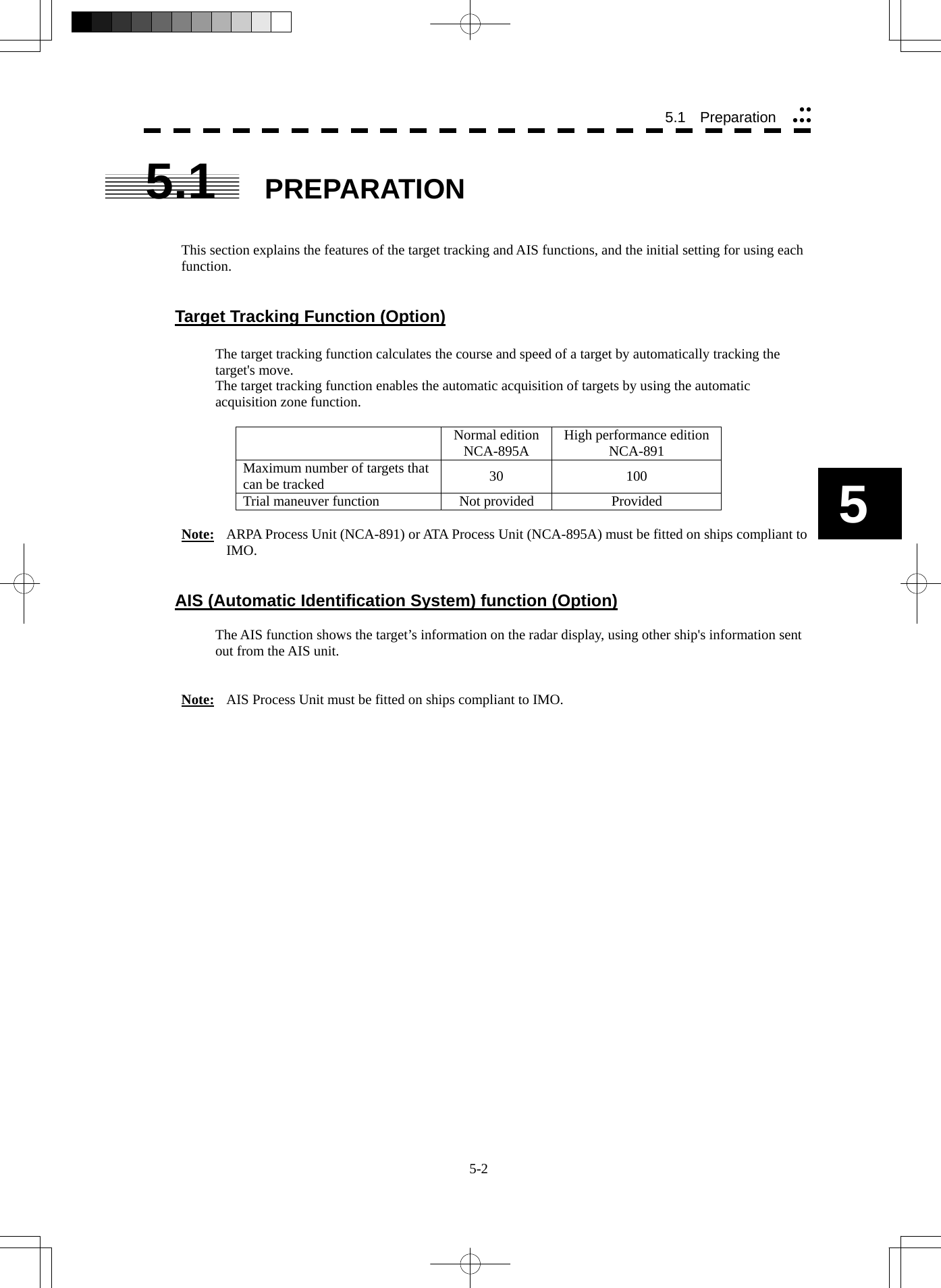
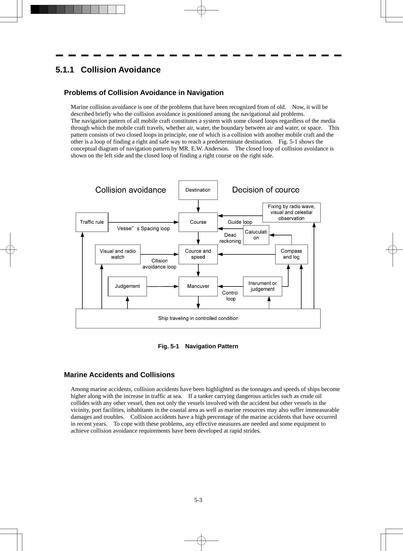
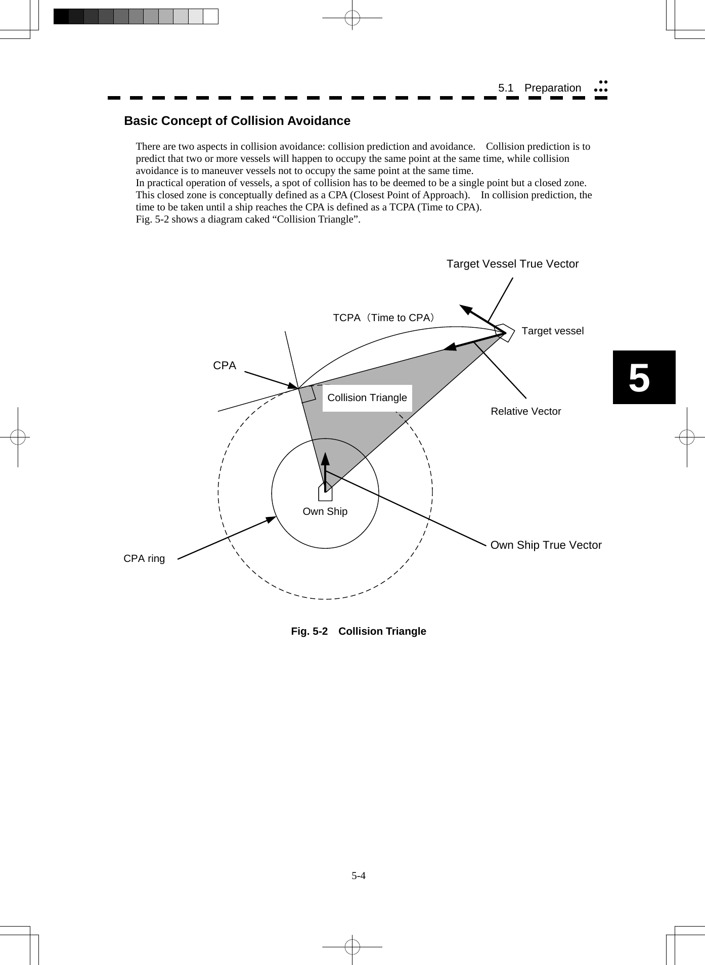
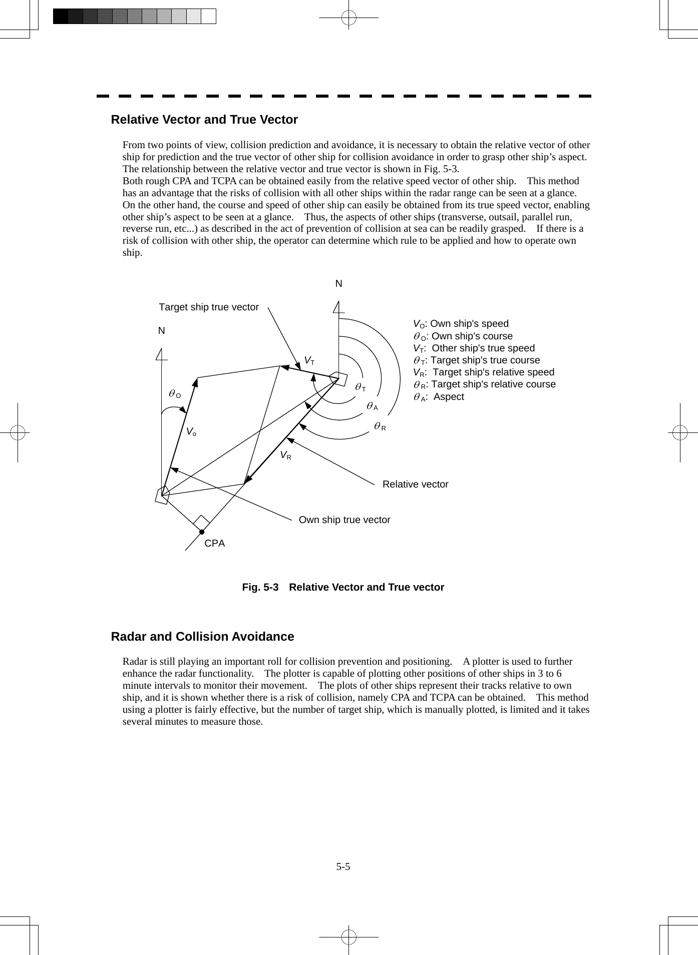
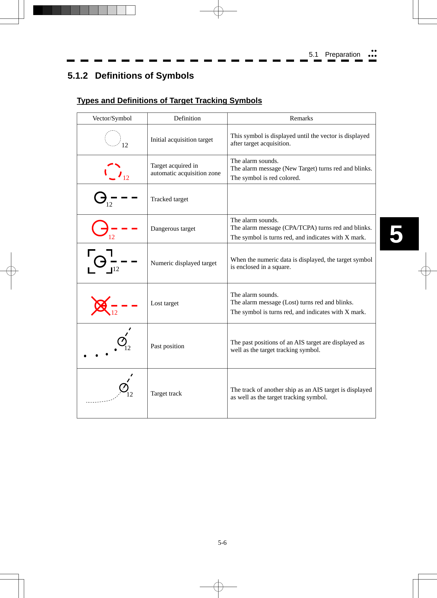
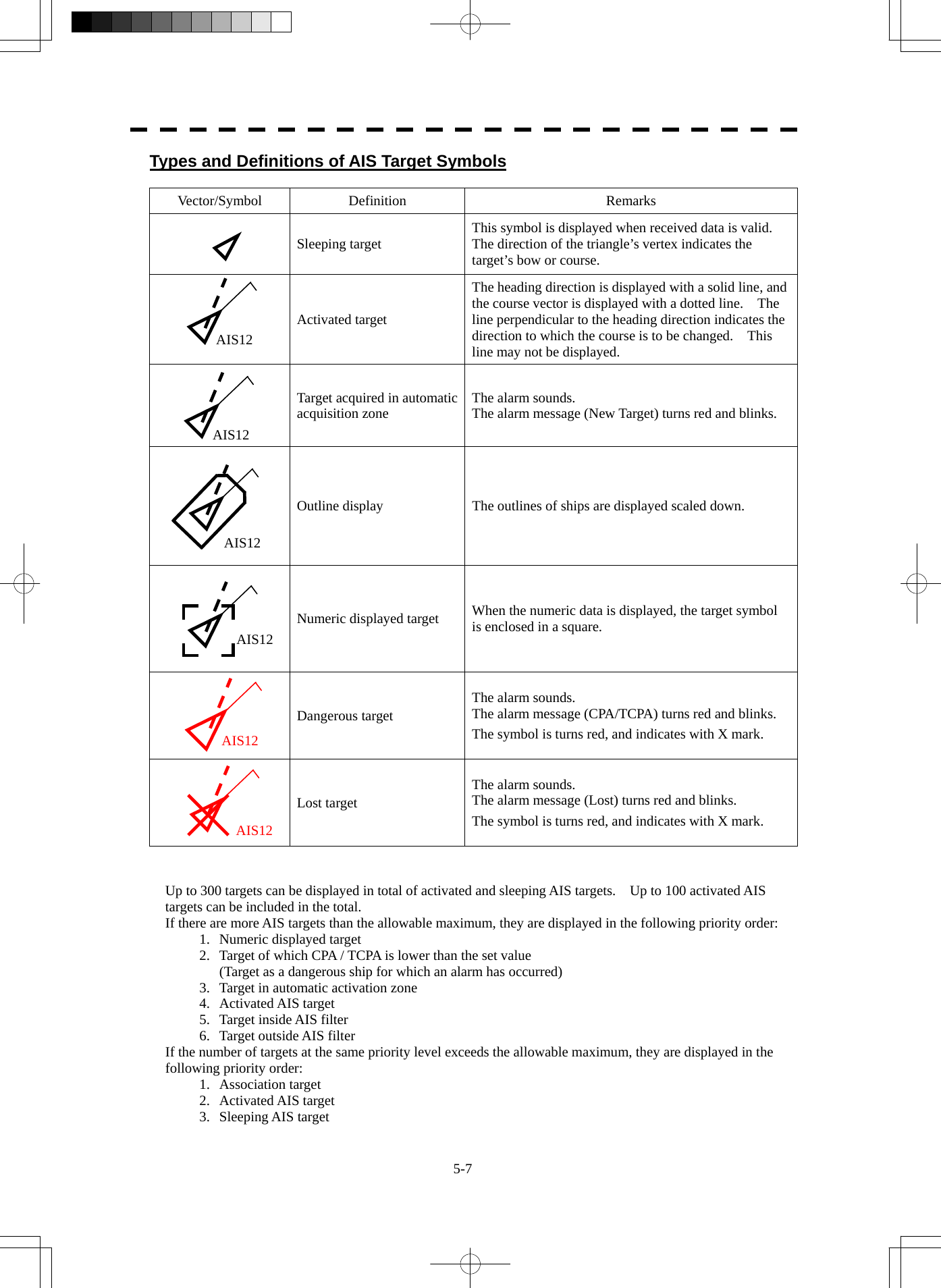
![5-8 5.1 Preparation yyyyy5 The vector of an AIS target is to be displayed with a vector over ground or over water, depending on the speed sensor setting and current offset setting. The type of the currently displayed vector can be confirmed by viewing the setting of the stable mode. When GND is displayed for the stability mode (upper left of the display on page 2-2): Vector over ground When Sea is displayed for the stability mode (upper left of the display on page 2-2): Vector over water When the vector of an AIS target is displayed with a vector over water, the system has converted the AIS target's vector over ground to the vector over water according to the data received from the AIS and the own ship's information. Note: When the AIS target's symbol is activated but the vector is not displayed, the following are probable causes of the trouble: COG/SOG is not yet input from the GPS. The selected speed sensor is malfunctioning. Types and Definitions of Association Target Symbols When a tracked target and an AIS target are decided as identical, it is displayed with either of the following symbols: Vector/Symbol Definition Remarks Priority for tracked targetAssociation target Priority for AIS target Association target Setting of Tracked Target Symbol Display This function switches the tracking target symbol display between on and off. Even if the tracking target symbol display is turned off, the data is retained. Procedures 1 Move the cursor onto the tracking target symbol display On / Off (TT / AIS information ⑨ on page 2-23), and press the [ENT] key. The tracking target symbol display will be set to on or off. Setting of AIS Target Symbol Display This function switches the AIS target symbol display between on and off. Procedures 1 Move the cursor onto the AIS target symbol display On / Off (TT/AIS information ⑩ on page 2-23), and press the [ENT] key. The AIS target symbol display will be set to on or off. AIS12 12](https://usermanual.wiki/Japan-Radio/NKE2254.Users-Manual/User-Guide-1510215-Page-246.png)
![5-9 5.1.3 Radar Display Vector Display A vector to represent a target’s predicted position can be presented in the True vector or Relative vector mode. In each mode, a vector length can be freely changed for a time interval of 1 to 60 minutes. To switch between the true vector mode and relative vector mode, press the [VECT R/T] key. [I] Vector Mode Selection True Vector Mode (Not used on the JPL-600-MK2 for VTS) In the true vector mode, the direction of a target vector indicates the true course of the target and its vector length is proportional to its speed. However, CPA Ring cannot appear in this mode. The relative vector isnot displayedTrue vectorHL](https://usermanual.wiki/Japan-Radio/NKE2254.Users-Manual/User-Guide-1510215-Page-247.png)
![5-10 5.1 Preparation yyyyy5 Relative Vector Mode (Not used on the JPL-600-MK2 for VTS) The relative vector does not represent the true motion of the target, but its relative relation with own ship. This means that a target with its relative vector directed to own ship (passing through the CPA Limit ring) will be a dangerous target. In the Relative Vector mode, it can be seen at a glance where the CPA Limit of the dangerous target is. The true vector isnot displayedRelative vectorCPA ringHL Therefore, the True / Relative mode shall optionally be used for the purpose of observation: the True vector mode for grasping the true aspect of a target, and the Relative vector mode for grasping a target’s closest point of approach (CPA). [II] Vector Length (Vector Time) The vector length of a target is proportional to its speed, and the vector time can be switched in a range of 1 to 60 minutes. The diagram below illustrates a vector length of a target for 6 minutes, and the tip of the vector represents the target’s position expected to reach 6 minutes later. Current positionFuture predicted position(6 min later in this example)HL Refer to Section 5.1.7 Setting Vectors for how to change the vector time.](https://usermanual.wiki/Japan-Radio/NKE2254.Users-Manual/User-Guide-1510215-Page-248.png)
![5-11 5.1.4 Cursor Modes (Cursor) Types and Functions of Cursor Modes The types of cursor modes are listed in the table below. To use the function of a cursor mode, move the cursor onto the PPI object and press the [ENT] key. Mode Function ACQ TT Enables the target tracking function to acquire a target in manual mode. ACT AIS Activates AIS targets, and sets a point filter. TGT Data Displays the numeric data of a tracked target or AIS target. CNCL TT Cancels a target tracking. DEACT AIS Deactivates AIS target. CNCL Data Hides the displayed numeric data of a tracked target or AIS target. Mark Puts a temporary mark. Property Displays the information of tracked targets, AIS targets, and marks. AUTO Changes operation in accordance with the object at the cursor position. Change of Cursor Mode Procedures 1 Move the cursor to the cursor mode Cursor (upper right of the display ① on page 2-19), and press the [ENT] key. On the PPI, press the [CLR / INFO] key and select a desired cursor mode from the list. The selected cursor mode will be shown at the cursor mode (upper right of the display on page 2-3). Note: If the function of a selected cursor mode is not used for one minute or more, the cursor mode is automatically changed to AUTO .](https://usermanual.wiki/Japan-Radio/NKE2254.Users-Manual/User-Guide-1510215-Page-249.png)
![5-12 5.1 Preparation yyyyy5 Operation of AUTO Mode As shown below, the AUTO mode performs operation in accordance with the object at the cursor position when the [ENT] key is pressed. Object at Cursor Position Operation None Acquires a target. EBL Performs EBL operation. VRM Performs VRM operation. Intersection point of EBL and VRM Performs EBL operation and VRM operation at the same time. Parallel index line (PI) Operates the parallel index line. Tracked target Displays the numeric data of the tracked target. Tracked target with numeric data displayed Hides the numeric data. Sleeping AIS target Activates the AIS target. Activated AIS target Displays the AIS target information. AIS target with numeric data displayed Hides the AIS target information. Automatic acquisition / activation zone Operates the automatic acquisition / activation zone. Sector radar alarm zone Operates the sector radar alarm zone. AIS filter zone Operates the AIS filter zone.](https://usermanual.wiki/Japan-Radio/NKE2254.Users-Manual/User-Guide-1510215-Page-250.png)
![5-13 z Set the optimum values of collision decision conditions, depending upon vessel type, water area, weather and oceanographic conditions. (For the relations between those conditions and alarms, refer to section 5.5 Alarm Display. ) 5.1.5 Setting Collision Decision Criteria (Not used on the JPL-600-MK2 for VTS) Input of CPA Limit Procedures 1 Move the cursor to the CPA limit setting (TT/AIS information ③ on page 2-23), and press the [ENT] key. The CPA Limit value input screen will appear. 2 Enter the value to be set as a CPA limit. For inputs to the value input screen, refer to Section 3.3.4. Input of TCPA Limit Procedures 1 Move the cursor to the TCPA limit setting (TT/AIS information ④ on page 2-23), and press the [ENT] key. The TCPA Limit value input screen will appear. 2 Enter the value to be set as a TCPA limit. For inputs to the value input screen, refer to Section 3.3.4. 5.1.6 Setting CPA Ring While the distance of the specified CPA Limit value is used as the radius, the CPA ring is displayed with a red circle. Procedures 1 Move the cursor to the CPA ring display On / Off (lower right of the display ⑦ on page 2-21), and press the [ENT] key. The CPA ring will be displayed. Note: The CPA ring is not displayed when the true vector mode is selected. Attention](https://usermanual.wiki/Japan-Radio/NKE2254.Users-Manual/User-Guide-1510215-Page-251.png)
![5-14 5.1 Preparation yyyyy5 5.1.7 Setting Vectors (Vector Time) Vector time can be set in minutes in the range 1 to 60 min. A true vector mode or relative vector mode can be selected. Setting vector time on the display Procedures 1 Move the cursor to the target vector time setting (TT / AIS information ② on page 2-23), and press the [ENT] key. The Vector Time value input screen will appear. 2 Enter the value to be set as vector time. For how to input numeric data on the numeric value input screen, see Section 3.3.4. Setting vector time using the multi-dial [MULTI] Procedures 1 Press the [MULTI] dial several times to activate the Vector mode. Vector will be displayed in the multi-dial mode (lower left of the display on page 2-3). 2 Turn the [MULTI] dial to set the vector time. Setting vector mode [VECT R / T] Procedures 1 Press the [VECT R / T] key. The current vector mode T (true vector) or R (relative vector) will be displayed in the target vector display true / relative switching (TT / AIS information ① on page 2-23).](https://usermanual.wiki/Japan-Radio/NKE2254.Users-Manual/User-Guide-1510215-Page-252.png)
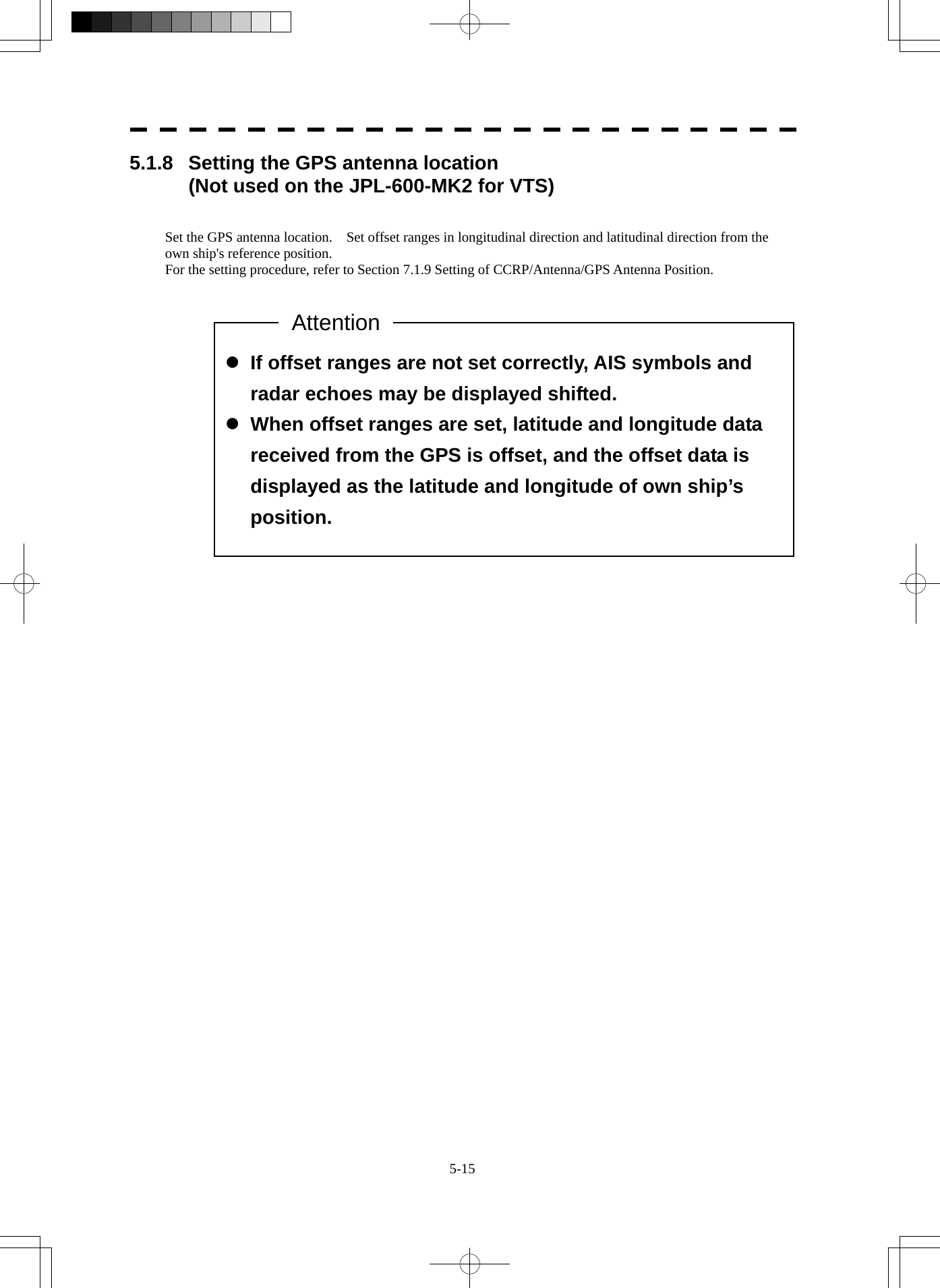
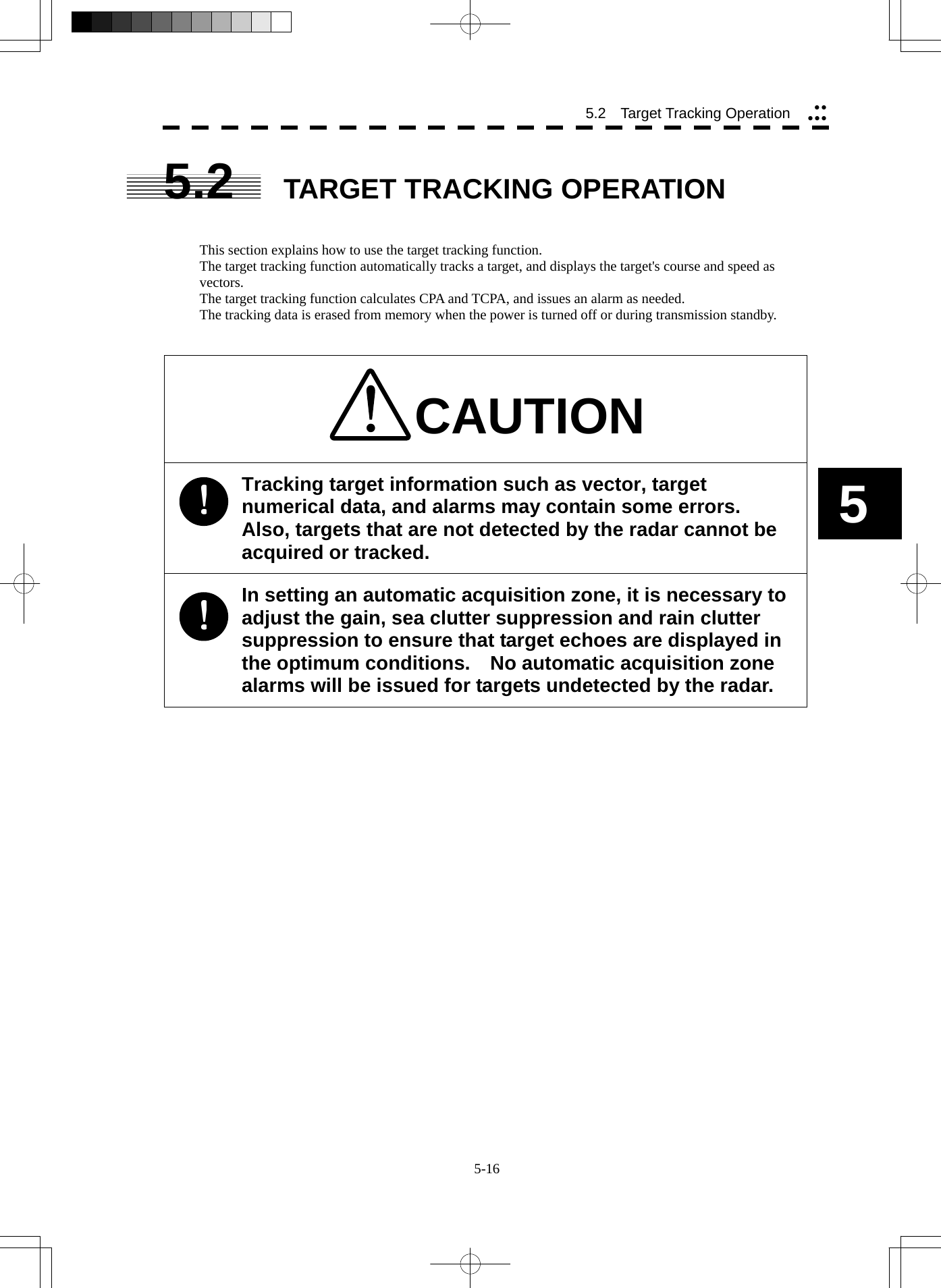
![5-17 5.2.1 Acquiring Target [ACQ] Target acquisition can be performed on two modes, Automatic and Manual, and both modes can be used at the same time. Automatic acquisition Note: If the number of targets being tracked has reached the allowable maximum and other targets (not being tracked) go into the acquisition/activation zone, automatically acquired targets are canceled in ascending order of danger. The position of the scanner shall be at the centre of the azimuth or range in the acquisition/activation zone. Turning On / Off the automatic acquisition and AIS activation (AZ Menu) Procedures 1 Press the [AZ] key for two seconds. The AZ Menu will appear. 2 Press the [1] or [2] key. The acquisition / activation zone 1 (AZ1) or acquisition / activation zone 2 (AZ2) will be set to on or off. On :The acquisition / activation zone is turned on. The mark " " and target ID number are put to an acquired target and move with the target. The vectors are displayed within 1 minute. AIS targets are activated. Off :The acquisition/activation zone is turned off. The acquisition/activation zone will disappear from the radar display, but the system continues to track the acquired target. The activated AIS targets remain activate.](https://usermanual.wiki/Japan-Radio/NKE2254.Users-Manual/User-Guide-1510215-Page-255.png)
![5-18 5.2 Target Tracking Operation yyyyy5 Creating the automatic acquisition and AIS activation Zone Procedures 1 Press the [AZ] key for 2 seconds. The AZ Menu will appear. 2 Open the Make AZ menu by performing the following menu operation. 3. Make AZ 3 Press [1] or [2] key. The range setting of the acquisition / activation zone 1 (AZ1) or acquisition / activation zone 2 (AZ2) will be started. 4 Set the starting azimuth and range by turning the [EBL] dial and [VRM] dial, and press the [ENT] key. 5 Set the ending azimuth and range by turning the [EBL] dial and [VRM] dial, and press the [ENT] key. The acquisition / activation zone will be determined. Setting the [AZ] key allocation (Set AZ Key) A generally used acquisition / activation zone can be turned on / off by simply pressing the [AZ] key. Procedures 1 Press the [AZ] key for 2 seconds. The AZ Menu will appear. 2 Open the AZ menu by performing the following menu operation. 5. Set AZ Key → 1. AZ 3 Set the assignment of the key. On :Pressing the [AZ] key turns on / off the acquisition / activation zone. Off :Pressing the [AZ] key does not turn on the acquisition / activation zone. Note: If the RADAR Alarm key assignment is set, pressing the [AZ] key turns on / off the Acquisition Zone at the same time the RADAR Alarm is turned on / off.](https://usermanual.wiki/Japan-Radio/NKE2254.Users-Manual/User-Guide-1510215-Page-256.png)
![5-19 Manual Acquisition [ACQ] Note: If more targets are acquired manually in the condition that the maximum number of targets are under tracking, the targets cannot acquired. Procedures 1 Move the cursor onto the target to be acquired, and press the [ACQ] key. The target will be acquired and the initial acquisition symbol will be displayed. The vector will be displayed within one minute. Target manually acquired.The initial acquisition symbol is displayed.Target that has passed for 1 min.The acquisition symbol and vector are displayed. To perform operation only in the manual acquisition mode without automatic acquisition/activation, turn off the automatic acquisition/activation function. Use of Automatic and Manual Acquisition Modes Use the manual acquisition mode while the automatic acquisition mode is on. Manually acquire the target to which particular attention should be paid, and get the other targets automatically acquired. If a new target appears exceeding the maximum number of targets, the manually acquired target is displayed even in the background until it gets out of the display. However, automatically acquired targets are canceled starting far distance from own ship.](https://usermanual.wiki/Japan-Radio/NKE2254.Users-Manual/User-Guide-1510215-Page-257.png)
![5-20 5.2 Target Tracking Operation yyyyy5 5.2.2 Canceling Unwanted Tracked Targets [TGT CNCL] Unwanted tracked targets can be canceled one by one in the following cases: • Tracking is no longer necessary for targets with which vectors/symbols are displayed after being acquired and tracked. • The number of vectors on the radar display needs to be reduced for easy observation. When targets are to be re-acquired from the beginning, all the current vectors can also be canceled. Canceling targets one by one [TGT CNCL] Procedures 1 Put the cursor on the tracked target to the desired for canceling target, and press the [TGT CNCL] key. The vectors and symbols of the tracked targets will disappear, and only the radar video remain. Canceling all targets collectively [TGT CNCL] Procedures 1 Press the [TGT CNCL] key for 5 seconds. The vectors and symbols of all the targets will disappear, and only the radar videos remain. Note: When all the targets have been canceled, the system stops tracking them. Thus, you need to re-acquire targets in manual or automatic acquisition mode. Do not cancel all the targets unless otherwise required.](https://usermanual.wiki/Japan-Radio/NKE2254.Users-Manual/User-Guide-1510215-Page-258.png)
![5-21 z When a target changes its course, or when a new target is acquired, its vector may not reach a given level of accuracy until 3 minutes or more has passed after such course change or target acquisition. Even if 3 minutes or more has passed, the vector may include an error depending upon the tracking conditions. 5.2.3 Tracked Target Data Display [TGT DATA] Type of Data Display (Target Information) Target Data Target identification (TT ID) ID number of the target True bearing (BRG) 0.1° unit Range 0.01 NM unit Course 0.1° unit Speed 0.1 knot unit Closest point of approach (CPA) 0.01 NM unit Time to CPA (TCPA) 0.1 min unit Bow crossing range (BCR) 0.01 NM unit Bow crossing time (BCT) 0.1 min unit The target for which its numeric data is displayed is marked with a symbol " " to distinguish from other targets. If a target’s data is displayed, but without the symbol " " , such a target exists outside the currently displayed radar display. Method of Displaying Numeric Data [TGT DATA] Procedures 1 Put the cursor on the tracked target for which numeric data is to be displayed, and press the [TGT DATA] key. Then, the data of the designated target will appear, it will be marked with a symbol " ". The target data will remain on the radar display until the target is lost and its vector disappears, or until another target is designated. If a target with the mark " " is designated, only its true bearing and range will appear until its vector appears. Attention](https://usermanual.wiki/Japan-Radio/NKE2254.Users-Manual/User-Guide-1510215-Page-259.png)
![5-22 5.2 Target Tracking Operation yyyyy5 Cancellation of Numeric Data Display (CNCL Data) Procedures 1 Put the cursor on the tracked target with which numeric data is displayed, and press the [CLR / INFO] key. The cursor mode list will appear. 2 Press the [6] key. The numeric value will disappear. 5.2.4 Displaying Target ID No. (Target Number Display) A target ID number is a value displayed beside the acquisition symbol when a target is acquired. A target ID number 1 to 100 is assigned to each target in acquisition order. Once a target ID number is assigned, it identifies the target until the target is lost or the target acquisition is canceled. Procedures 1 Press the [TT MENU] key. 2 Press the [4] key. Target Number Display will appear. 3 Press the [numeric] key corresponding to the display method to be set. On :Displays target ID numbers. Off :Hides target ID numbers. Target Track :Displays target ID number with ship track. If there are many tracking targets and their symbol display is confusing, set Target Number Display to off to view the radar display easily. Note: An ID number is always displayed for only targets with which numeric data is displayed.](https://usermanual.wiki/Japan-Radio/NKE2254.Users-Manual/User-Guide-1510215-Page-260.png)
![5-23 5.2.5 Adding Tracked Target ID Name (Name) The system can enter a name for each of tracking targets that have been acquired. Procedures 1 Put the cursor on the tracked target, and press the [CLR / INFO] key. The cursor mode list will appear. 2 Press the [8] key. The TT Target Information will appear. 3 Press the [1] key. The setting items for ship name (Name) will be displayed. 4 Select the input method. Data Base : Selection of one of previously input ship names. When this method is selected, a list of ship names that have been input by selecting Input will be displayed. Input : Input of a new ship name. When this method is selected, the ship name (Name) input window will open. Off : Target ship's name is not displayed. Entering a new ship name (Input) 5 Input a new ship name. Up to 8 characters can be input as a ship name. For the input method on the character input screen, see Section 3.3.4. The input name by selecting Input is saved in Data Base . Selecting one of previously input ship names (Data Base) 5 Press the [numeric] key corresponding to the ship name to be selected. The selected ship name will be entered. * Data Base can contain 30 ship names.](https://usermanual.wiki/Japan-Radio/NKE2254.Users-Manual/User-Guide-1510215-Page-261.png)
![5-24 5.2 Target Tracking Operation yyyyy5 z If the REF. is selected for the speed sensor, the AIS function cannot be turned on. 5.2.6 Reference Target (Reference) (Not used on the JPL-600-MK2 for VTS) The system can display the own ship's speed. To do so, it sets a reference target by tracking a target for which ground fixed. Procedures 1 Tracking a target for which ground fixed. 2 Put the cursor on the tracked target, and press the [CLR / INFO] key. The cursor mode list will appear. 3 Press the [8] key. The Property will appear. 4 Press the [3] key. The reference target function will be set to on or off. On :A reference target is set. Off :The reference target is canceled. 5 Put the cursor on the speed sensor switching (Own ship information ② on page 2-22), press the [ENT] key, and select REF. . The speed of own ship calculated from the reference target will be displayed. When a reference target is set, the symbol display is changed to " R ". Only one target can be set as a reference target. When a new reference target is set, the previously set reference target is canceled. Note: If AIS function is set to on, the reference target function cannot be used. Attention](https://usermanual.wiki/Japan-Radio/NKE2254.Users-Manual/User-Guide-1510215-Page-262.png)
![5-25 5.2.7 Operation Test (TT Test Menu) CAUTION Target Tracking Function Test is provided to test if the target tracking function is operating normally. Thus, do not use the function except when you test the target tracking function. The following functions are available for testing the target tracking function: [I] Test Video Makes an operation check on the target detection circuit. [II] TT Simulator Generates pseudo targets on the radar display in order to test if the target tracking function is operating normally. [III] Status Displays the status of the target tracking function. [IV] Gate Display Displays the gate size for acquiring / tracking a target.](https://usermanual.wiki/Japan-Radio/NKE2254.Users-Manual/User-Guide-1510215-Page-263.png)
![5-26 5.2 Target Tracking Operation yyyyy5 [I] Test Video Test Video is used to check whether the video signals under target acquisition and tracking are inputted to and processed in the target detection circuit normally. However, it is sufficient to check that VDH in Test Video is displayed. Note: Test Video may not be displayed for a target which is not yet acquired or tracked. Test Video may not be displayed either if the [GAIN] dial or [SEA] dial is not properly adjusted. Procedures 1 Press the [TT MENU] key. 2 Open the TT Test Menu by performing the following menu operation. 9. TT Test Menu 3 Press the [1] key. The setting items for Test Video will be displayed. 4 Select the test video to be displayed. In general, VDH is sufficient for target display checks in test video mode. If any target displayed clearly in the radar display is not displayed in the Test Video mode, the target detection circuit of the Target Tracking unit may have a trouble Cancellation 1 Press the [1] key while the TT Test Menu is displayed. The setting items for Test Video will be displayed. 2 Press the [1] key The test video display will be turned off.](https://usermanual.wiki/Japan-Radio/NKE2254.Users-Manual/User-Guide-1510215-Page-264.png)
![5-27 [II] Target Tracking Simulator Pseudo targets can be generated in certain known positions to check whether the target tracking units are operating normally. Since the pseudo targets move depending on known parameters, the values for these pseudo targets can be compared with the known value if the pseudo targets are acquired and tracked, and displayed. Thus, it can be checked if the system is operating normally. Procedures 1 Press the [STBY] key. The equipment will enter the transmission standby state. 2 Press the [TT MENU] key. 3 Open the TT Test Menu by performing the following menu operation. 9. TT Test Menu 4 Press the [2] key. The setting items for TT Simulator will be displayed. 5 Select the scenario to be set. The TT Simulator display will be turned on. 6 Press the [TX / PRF] key. When the TT simulator is active, the character " X " will display at the bottom of the radar display. Target tracking simulator / scenario Target start point Target end point Scenario Distance Bearing Distance Bearing Pseudo-target speed 1 3.2 nm 20 ° 1 nm 90 ° 20 kn 2 6 nm 0 ° 0 nm 0 ° 10 kn 3 6 nm every 18 °1 nm every 18 ° 10 kn 4 6 nm 45 ° 1 nm 45 ° 105 kn 5 6 nm 45 ° 6 nm 150 ° 20 kn 6 6 nm 45 ° 6 nm 150 ° 20 kn Cancellation 1 Press the [STBY] key. The equipment will enter the transmission standby state. 2 Press the [2] key while the TT Test Menu is displayed. The setting items for TT Simulator will be displayed. 3 Press the [1] key. The TT Simulator display will be turned off.](https://usermanual.wiki/Japan-Radio/NKE2254.Users-Manual/User-Guide-1510215-Page-265.png)
![5-28 5.2 Target Tracking Operation yyyyy5 [III] Status display (Status) The current Target Tracking status will appear. Procedures 1 Press the [TT MENU] key. 2 Open the TT Test Menu by performing the following menu operation. 9. TT Test Menu 3 Press the [3] key. The setting items for Status will be displayed. *Constant : Vector response *VID Level TD : Threshold value used for automatic acquisition *VID Level High : Threshold value used for tracking *VID Level Low : Unused *Gate Size : Size of gate used for tracking *Tracking : Number of targets currently acquired](https://usermanual.wiki/Japan-Radio/NKE2254.Users-Manual/User-Guide-1510215-Page-266.png)
![5-29 [IV] Gate Display The gate displays an area monitoring a target using the Target Tracking function. This radar equipment allows the gate size to change automatically according to target range and size. User can check the gate size using the following function. Procedures 1 Press the [TT MENU] key. 2 Open the TT Test Menu by performing the following menu operation. 9. TT Test Menu 3 Press the [4] key. The gate display mode is switched. On : Gate is displayed Off : Gate is not displayed 4 Display the numeric value of a target according to Section 5.2.3. The numeric value of the target will be displayed, and the tracked target symbol will be enclosed in a green gate. Note: The Target Tracking can display the gate of two targets simultaneously.](https://usermanual.wiki/Japan-Radio/NKE2254.Users-Manual/User-Guide-1510215-Page-267.png)
![5-30 5.3 AIS Operation yyyyy5 z When the AIS function is set to Off, the AIS display function is turned off and AIS symbols are no longer displayed. z Once the AIS display function is set to Off, it is not automatically switched to On even if a dangerous target exists. 5.3 AIS OPERATION 5.3.1 Restrictions The following restrictions are placed on use of the AIS function. • The AIS function is unavailable in the following cases: a) MAN or REF. is selected for the speed sensor. b) The current offset (Set/Drift Setting) is set while LOG or 2AXW is selected for the speed sensor. c) The GPS geodetic system is used except WGS-84. • LOG or 2AXW cannot be selected for the speed sensor in the following case: The AIS function is turned on and the current offset (Set/Drift Setting) is selected. • MAN cannot be selected for the speed sensor in the following case: The AIS function is On. • Current offset (Set/Drift Setting) cannot be turned On in the following case: LOG or 2AXW is selected for the speed sensor while the AIS function is on. 5.3.2 Setting AIS Display Function (AIS Function) Procedures 1 Put the cursor on the AIS On / Off (TT / AIS information ⑧ on page 2-23), and press the [ENT] key. The received AIS information will be shown on the radar display. Attention](https://usermanual.wiki/Japan-Radio/NKE2254.Users-Manual/User-Guide-1510215-Page-268.png)
![5-31 5.3.3 Activate AIS Targets (Activate AIS) Activate an AIS target, and display the target’s vector and make a collision decision. Manual activation (ACT AIS) Activate an AIS target in manual mode to display the vector and heading line. Procedures 1 Put the cursor on the AIS symbol to be activated, and press the [CLR/INFO] key. The setting items for cursor modes will be displayed. 2 Press the [2] key. The selected AIS target will be activated. Automatic activation (AUTO Activate) Activate an AIS target in automatic mode to display the vector and heading line. When the automatic activation function is used, AIS targets are automatically activated when they go into the automatic activation zone. The automatic activation zone is identical to the automatic acquisition zone (AZ) used for target tracking. For the zone setting, refer to " Acquiring Target " in Section 5.2.1 The position of the scanner shall be at the centre of the azimuth or range in the acquisition/activation zone. If there are more AIS targets than the allowable maximum, they are deactivated in the low-priority (See the section 5.1.2). Reference If an AIS target is activated but the vector is not displayed, refer to " Displaying Target ID Number " in section 5.3.6 5.3.4 Deactivate AIS Targets (Deactivate AIS) Deactivate an AIS target and clear the display of the vector and heading line. Procedures 1 Put the cursor on the AIS target to be deactivated, and press the [CLR/INFO] key. The setting items for cursor modes will be displayed. 2 Press the [5] key. The selected AIS target will be deactivated. Note: This operation is available only for an activated AIS target.](https://usermanual.wiki/Japan-Radio/NKE2254.Users-Manual/User-Guide-1510215-Page-269.png)
![5-32 5.3 AIS Operation yyyyy5 5.3.5 Displaying AIS Information [TGT DATA] Types of information displayed There are two modes (simple and detail) to display AIS target information. The display items are determined by the selected mode. Display Item Detail mode Simple mode NAME (ship name) Up to 20 characters Call Sign Up to 7 characters MMSI Up to 9 characters COG (course over ground) or CTW (course through water) 0.1 ° unit SOG (speed over ground) or STW (speed through water) 0.1 knot unit CPA (closest point of approach) 0.01 nm unit TCPA (time to CPA) 0.1 min unit BRG (true bearing) 0.1 ° unit Range 0.01 nm unit HDG (heading bearing) 0.1 ° unit ROT (rate of turn) 0.01 °/min POSN (latitude / longitude) 0.0001’ unit Destination (waypoint) Up to 20 characters NAV Status Status (number) Not displayed If the numeric information of ROT is blank, the radar is receiving the AIS data which is cannot displayed. In this case, you can only trust the turning direction which is indicated by the turn indicator. The turn indicator is displayed on the AIS symbol as the line perpendicular to the heading direction. (See the Section 5.1.2 "Types and Definitions of AIS Target Symbols") If the numeric information of SOG or STW is 102.2kn, the target ship's speed is 102.2kn or over. Then the system cannot calculate CPA and TCPA. Therefore, missing is indicated in the CPA and TCPA information. The detail mode displays the numeric data of only a single ship, the simple mode can display the numeric data of up to two ships. For NAV Status, one of the following statuses is displayed in accordance with Navigation Status: No. Status 0 Under Way Using Engine 1 at Anchor 2 Not Under Command 3 Restricted Maneuverability 4 Constrained by Her Draft 5 Moored 6 Aground 7 Engaged in Fishing 8 Under Way Sailing 9 Reserved 10 Reserved 11-14 Reserved 15 Not Defined](https://usermanual.wiki/Japan-Radio/NKE2254.Users-Manual/User-Guide-1510215-Page-270.png)
![5-33 Displaying AIS Target Information [TGT DATA] Procedures 1 Put the cursor on the AIS target of which information is to be displayed , and press the [TGT DATA] key. The information of the selected AIS target will be displayed. Reference: When the numeric data of a target is displayed but the mark " " is not on the radar display, the target is outside the display. Canceling AIS Target Information Display (CNCL Data) Procedures 1 Put the cursor on the activated AIS target of which information display is to be cancelled, and press the [CLR / INFO] key. The setting items for cursor modes will be displayed. 2 Press the [6] key. The information display of the selected AIS target will be cleared. Selecting Detail / Simple Mode for AIS Target Information Display Procedures 1 Put the cursor on the detail/simple display switching (AIS target information ① on page 2-25), and press the [ENT] key. The detail or simple mode display for AIS target information will be selected.](https://usermanual.wiki/Japan-Radio/NKE2254.Users-Manual/User-Guide-1510215-Page-271.png)
![5-34 5.3 AIS Operation yyyyy5 Message Received AIS messages can be displayed. Up to 10 messages of addressed message and up to 10 messages of broadcast message can be displayed. If the number of messages exceeds 10, the oldest received messages are sequentially deleted. Displaying Message Selected from List (Message) Procedures 1 Press the [RADAR MENU] key twice. 2 Open the Message menu by performing the following menu operation. 7. AIS Menu → 7. Message 3 Press the [1] or [2] key. Pressing [1] key lists addressed messages; pressing [2] key lists broadcast messages. Each list shows ship names and message-received time. For an unread message, * is displayed to the left of the item number. 4 Press the [numeric] key corresponding to the message to be displayed. The message will appear. Displaying Specified Target's Message Procedures 1 Display AIS target information. If there are messages from the target, a message mark will be displayed in the unread message display field (AIS target information ② on page 2-25). 2 Put the cursor on the unread message display (AIS target information in ② on page 2-25), and press the [ENT] key. The message will appear. Deleting Message (Delete) Procedures 1 Press the [1] key while the message is displayed. The Confirmation Window will appear. 2 Press the [1] key. The message will be deleted, and the ship name and message-received time will disappear from the list.](https://usermanual.wiki/Japan-Radio/NKE2254.Users-Manual/User-Guide-1510215-Page-272.png)
![5-35 Displaying Data of Lost AIS Target (Display Lost TGT Data) The data of the last-lost AIS target can be displayed. The data of only one target that has been lost most recently can be displayed. Procedures 1 Press the [RADAR MENU] key twice. 2 Open the Display Lost Target Data menu by performing the following menu operation. 7. AIS Menu → 8. Display Lost TGT Data The data of the last-lost AIS target will be displayed. Displaying Own Ship's AIS Data (Own Ship's AIS Data) (Not used on the JPL-600-MK2 for VTS) The AIS data of own ship can be displayed. Procedures 1 Press the [RADAR MENU] key twice. 2 Open the Own Ship's AIS Data menu by performing the following menu operation. 7. AIS Menu → 9. Own Ship’s AIS Data The own ship's AIS data will be displayed.](https://usermanual.wiki/Japan-Radio/NKE2254.Users-Manual/User-Guide-1510215-Page-273.png)
![5-36 5.3 AIS Operation yyyyy5 5.3.6 Displaying Target ID No. (Target Number Display) When an AIS target is activated, a target ID number is displayed next to the AIS target symbol. A target ID number 1 to 100 is assigned to each target in activation order. Once a target ID number is assigned, it identifies the target until the target is lost or deactivated. Procedures 1 Press the [RADAR MENU] key twice. 2 Open the Target Number Display menu by performing the following menu operation. 7. AIS Menu → 5. Target Number Display 3 Press the [numeric] key corresponding to the display method to be set. On : Displays target ID numbers. Off : Hides target ID numbers. Target Track : Displays target ID number with AIS track. Ship's Name : Displays the ship's name. If there are many tracking targets and their symbol display is confusing, set Target Number Display to off to view the radar display easily. Note: An ID number or ship's name is always displayed for only targets with which numeric value is displayed. 5.3.7 Setting AIS Filter (AIS Filter Setting) About an AIS filter By setting an AIS filter, an AIS target in the area can be displayed by priority or only the targets in the area can be displayed. An AIS filter is initially set in a circle having a radius of 20 [nm] from the radar station. If 301 or more AIS targets exist in the filter range, they are displayed in the priority order explained in Section 5.1.2 Symbols - Types and Definitions of AIS Target Symbols. Types of AIS Filters (Filter Type) There are the following 3 types of AIS filters: Range :A filter is set in a circle with a set range as the radius. Sector :A filter is set in a sector formed by two bearings with the bow as reference. Zone :A filter is set in a zone formed by two bearings and two ranges with the bow as reference. Procedures 1 Put the cursor on the AIS filter mode switching (TT / AIS information ⑫ on page 2-23), and press the [ENT] key to select the filter to be set. The AIS filter will be selected.](https://usermanual.wiki/Japan-Radio/NKE2254.Users-Manual/User-Guide-1510215-Page-274.png)
![5-37 Creation of AIS Filter (Make AIS Filter) Procedures 1 Press the [RADAR MENU] key twice. 2 Open the AIS Filter Setting menu by performing the following menu operation. 7. AIS Menu → 4. AIS Filter Setting 3 Press the [2] key. The mode to make an AIS filter will be activated. [I] Setting Range Filter 4 Set a filter range by turning the [VRM] dial, and press the [ENT] key. [II] Setting Sector Filter 4 Set a starting bearing by turning the [EBL] dial, and press the [ENT] key. 5 Set an ending bearing by turning the [EBL] dial, and press the [ENT] key. [III] Setting Zone Filter 4 Set a starting bearing and range by turning the [EBL] dial and [VRM] dial, and press the [ENT] key. 5 Set an ending bearing and range by turning the [EBL] dial and [VRM] dial, and press the [ENT] key. Note: When the automatic activation function is enabled, the filter range is automatically changed for covering the automatic activation zone. Thus, the automatic activation zone is always within the filter range. AIS Filter Display On/Off (Filter Display) Procedures 1 Press the [RADAR MENU] key twice. 2 Open the AIS Filter Setting menu by performing the following menu operation. 7. AIS Menu → 4. AIS Filter Setting 3 Press the [3] key. Filter Display will be set to on or off.](https://usermanual.wiki/Japan-Radio/NKE2254.Users-Manual/User-Guide-1510215-Page-275.png)
![5-38 5.3 AIS Operation yyyyy5 Display of Targets outside AIS Filter (Filter Mode) Procedures 1 Press the [RADAR MENU] key twice. 2 Open the Filter Mode menu by performing the following menu operation. 7. AIS Menu → 6. Filter Mode 3 Press the [6] key. The Filter Mode is switched. Display : Displays only AIS targets in the AIS filter. Priority : Displays AIS targets in the AIS filter by priority, and also displays targets outside the AIS filter. Note: Activated AIS targets can be displayed even when they are outside the AIS filter. Point Filter AIS targets which are not displayed because they are outside the AIS filter or at low priority levels can be activated by giving a higher priority to them. Procedures 1 Put the cursor on the position where a point filter is to be set, and press the [CLR / INFO] key to select the filter to be set. The setting items for cursor modes will be displayed. 2 Press the [2] key. A point filter will be set at the cursor position. If an AIS target is in the point filter, it will be activated. When an AIS target is activated or an AIS target is not found within one minute, the point filter will be cleared. Note: The point filter's range is 1 nm, and cannot be changed.](https://usermanual.wiki/Japan-Radio/NKE2254.Users-Manual/User-Guide-1510215-Page-276.png)
![5-39 5.3.8 Conditions for Deciding AIS Target to be Lost About a lost target When the data of an AIS target cannot be received for a specified time, the target is decided to be lost and the target data is deleted. As shown in the table below, the time until target data is deleted varies depending on the class of receive data and the target status. Deciding AIS Target to be Lost Time until data deletion Target status SOLAS ship (Class A) SOLAS ship (Class B) Vessel below 3 knots (Class A) or 2 knots (Class B) and it is now at anchor or on the berth 18 min 18 min Vessel of 3 knots or more and it is now at anchor or on the berth 60 sec 18 min Vessel of 0 to 14 knots (Class B: 0 to 14 knots) 60 sec 180 sec Vessel of 14 to 23 knots 36 sec 180 sec Vessel of 23 knots or more 30 sec 180 sec SAR (Search and Rescue) 60 sec 60 sec ATON (Aid to Navigation) 18 min 18 min Base Station 60 sec 60 sec Reference: When a dangerous target ship is lost, a lost alarm is issued and the symbol changes to a lost symbol. The lost symbol will display continuously on the last-received position. If the [ALARM ACK] key is pressed, the symbol is cleared.](https://usermanual.wiki/Japan-Radio/NKE2254.Users-Manual/User-Guide-1510215-Page-277.png)
![5-40 5.3 AIS Operation yyyyy5 5.3.9 Setting Conditions for AIS Alarm (AIS Alarm Setting) Conditions for issuing a Lost alarm and CPA/TCPA alarm for AIS targets can be set. Setting of Condition for Lost Alarm Procedures 1 Press the [RADAR MENU] key twice. 2 Open the AIS Alarm Setting menu by performing the following menu operation. 7. AIS Menu → 6. AIS Alarm Setting 3 Press the [1] key. The setting items for Lost Alarm will be displayed. 4 Press the [numeric] key corresponding to the condition to be set. Off : A lost alarm is not issued. Danger : A lost alarm is issued only for AIS targets for which a dangerous target alarm has been issued. ACT&Danger : A lost alarm is issued only for activated AIS targets and AIS targets for which a dangerous target alarm has been issued. ACT&Danger&Select : A lost alarm is issued only for activated AIS targets, data indicated AIS targets and AIS targets for which a dangerous target alarm has been issued. Note: A lost alarm is not issued for sleeping AIS targets. Setting of Condition for CPA/TCPA Alarm Procedures 1 Press the [RADAR MENU] key twice. 2 Open the AIS Alarm Setting menu by performing the following menu operation. 7. AIS Menu → 6. AIS Alarm Setting 3 Press the [2] key. The setting items for CPA/TCPA Alarm is switched. Off : A CPA/TCPA alarm is not issued. ACT : A CPA/TCPA alarm is issued only for activated AIS targets. ACT&Sleep : A CPA/TCPA alarm is issued for all AIS targets on the radar display. Note: When the Lost Alarm menu set to Off, the CPA ring color changes to dark color.](https://usermanual.wiki/Japan-Radio/NKE2254.Users-Manual/User-Guide-1510215-Page-278.png)
![5-41 z Turn off Association in order not to make a decision on if targets are identical, or in order to display symbols that have disappeared. 5.4 DECISION OF TARGETS AS IDENTICAL (ASSOCIATION) CAUTION If a great value is set as a condition for deciding targets as identical, a tracking target near an AIS target is regarded as identical to the AIS target and it may not be displayed any more. For example, when a pilot boat (which is a small target not being tracked) equipped with an AIS function approaches a cargo ship as a tracking target not equipped with an AIS function, the tracking target symbol of the cargo ship may not be displayed any more. Setting of Function to Decide Targets as Identical (Association) When an AIS target and a tracking target are decided to be identical, an association symbol is displayed for the targets regarded as identical. In this case, the AIS target symbol is automatically activated. Procedures 1 Put the cursor on the association On/Off (TT/AIS information ⑪on page 2-23), and press the [ENT] key. Association will be set to on or off. Attention](https://usermanual.wiki/Japan-Radio/NKE2254.Users-Manual/User-Guide-1510215-Page-279.png)
![5-42 5.4 Decision of Targets as Identical yyyyy5 Setting of Conditions for Deciding AIS and Tracked Targets as Identical (Association Setting) Procedures 1 Press the [TT MENU] key. 2 Press the [1] key. The Association Setting menu will appear. 3 Select and enter the item to be set. Conditions for deciding targets as identical will be set. When the differences of all item between AIS and tracked target are under the set conditions.. Once regard as identical, when one of the differences exceed 125 % of the set condition, they are regarded as dissidence. * The setting for this function is common to Association Setting in the AIS Menu. Types of Decision Conditions to be Set Decision conditions 1. Association On / Off (Function to decide targets as identical) 2. Priority AIS / TT (Symbol to be displayed) 3. Bearing 0.0 to 9.9 ° 4. Range 0 to 999 m 5. Course 0 to 99 ° 6. Speed 0 to 99 kn 7.Applicable AIS Target ACT or ACT&Sleep (activated AIS target or all AIS target)](https://usermanual.wiki/Japan-Radio/NKE2254.Users-Manual/User-Guide-1510215-Page-280.png)
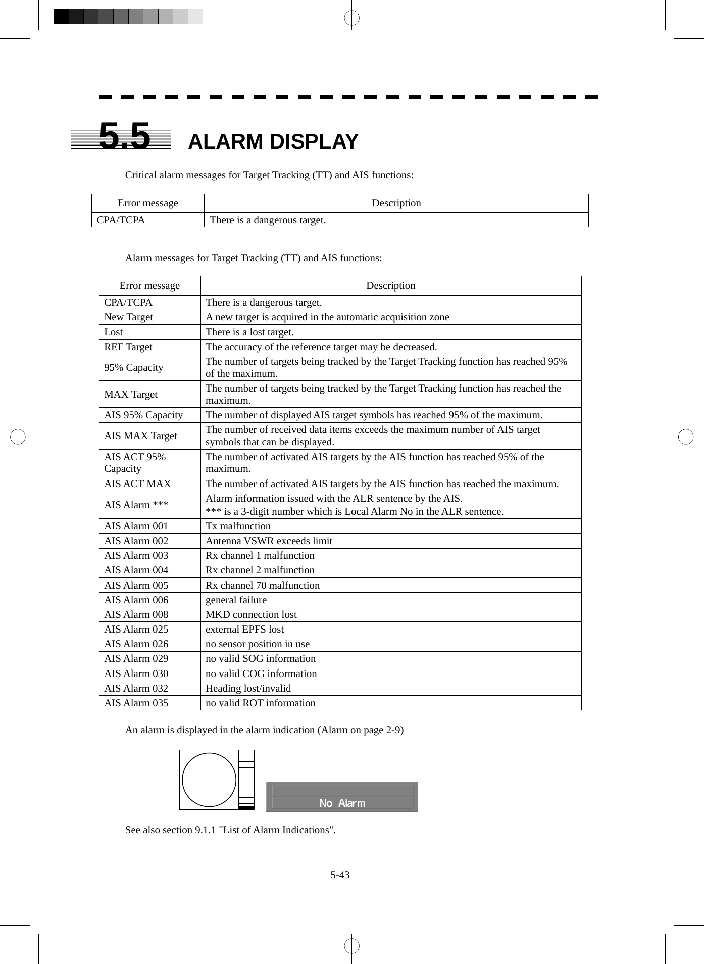
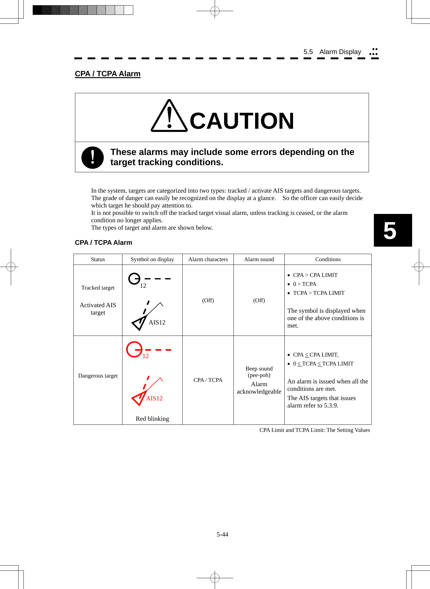
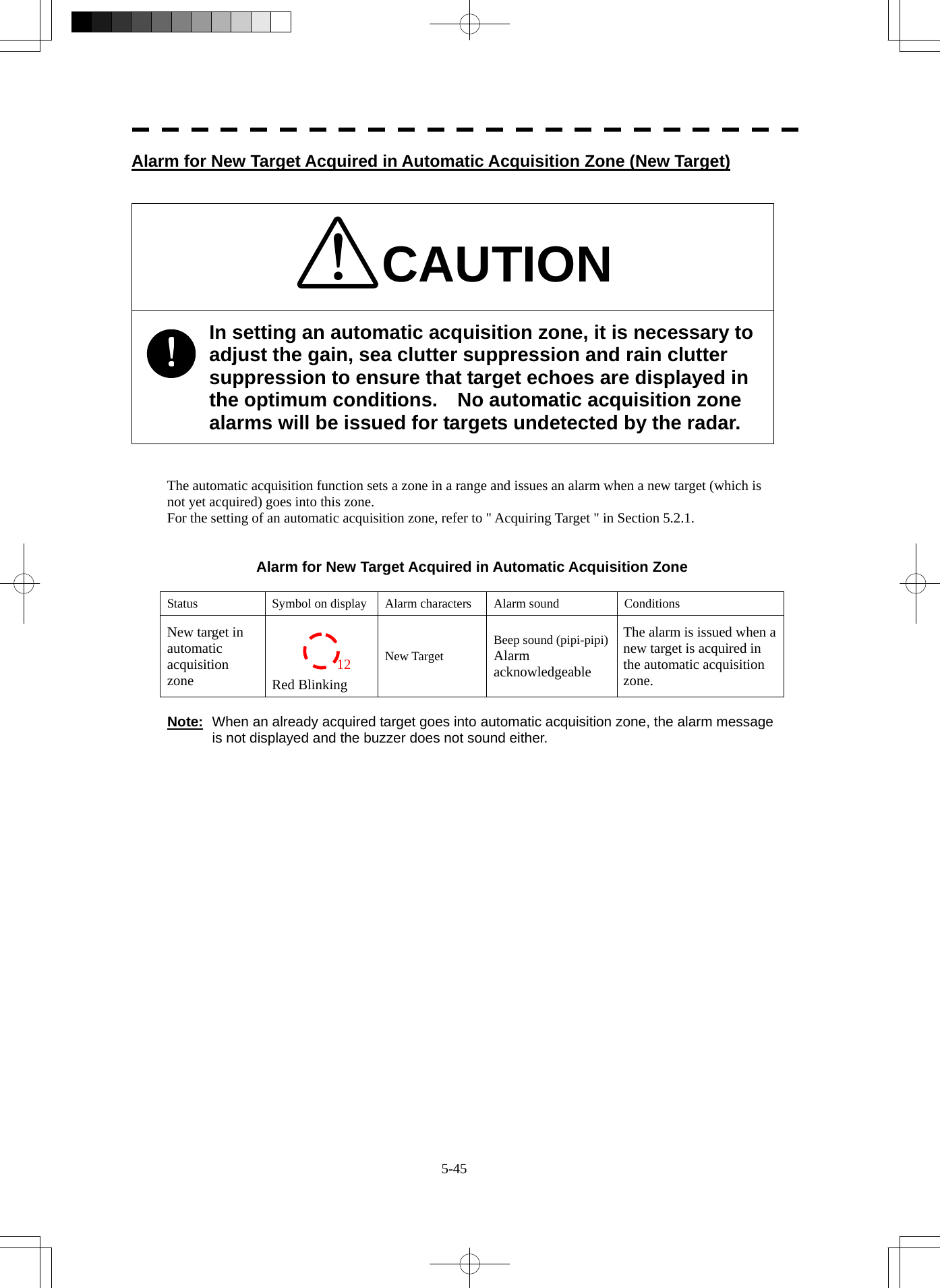
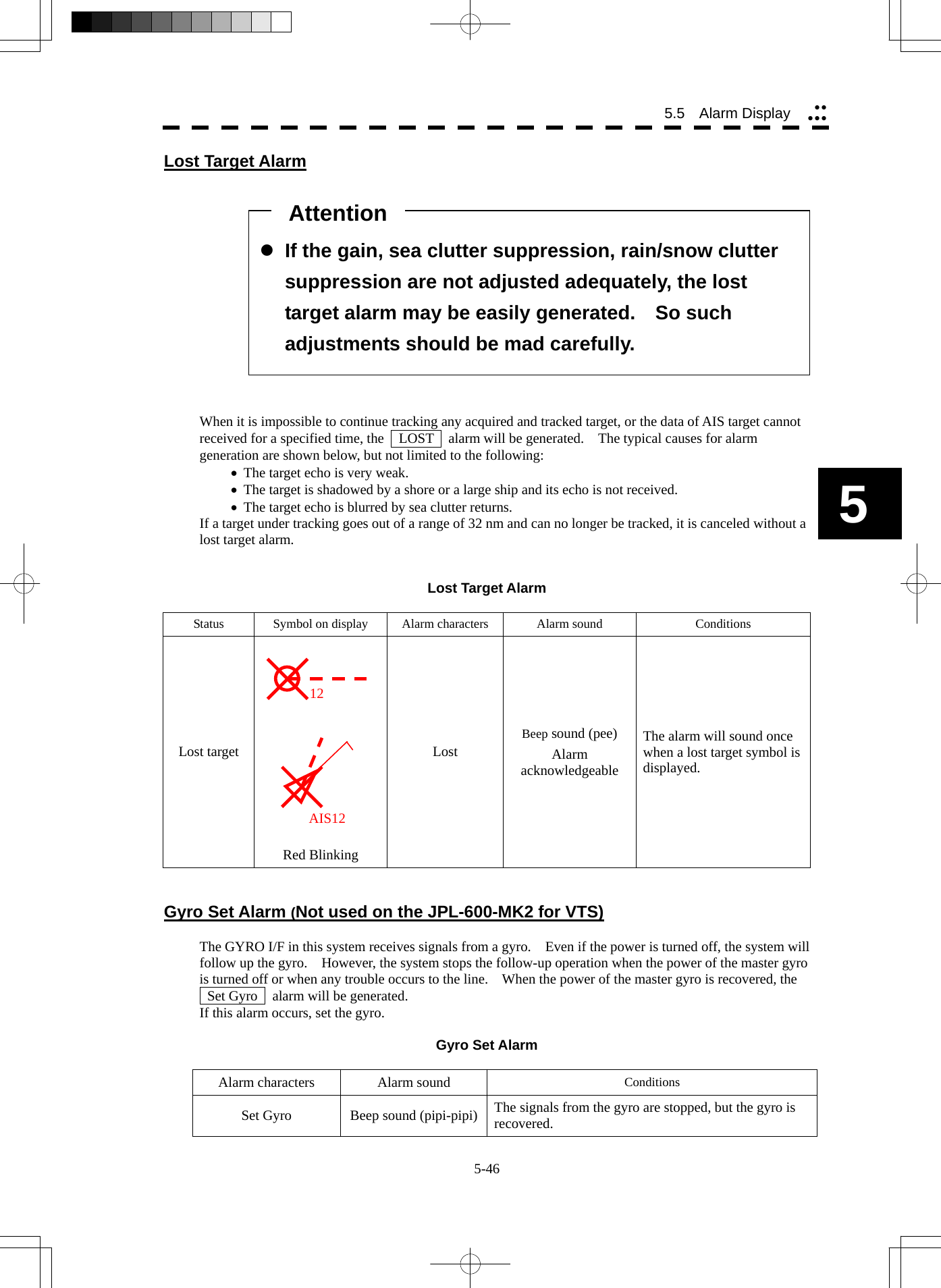
![5-47 5.6 TRACK FUNCTION 5.6.1 Past Position (Past POSN) Procedures 1 Put the cursor on the past position display interval unit switching (TT/AIS information ⑦ on page 2-23), and press the [ENT] key to set a desired unit. The past position display interval unit will be set to min or NM . 2 Put the cursor on the past position display interval switching (TT/AIS information ⑥ on page 2-23), and press the [ENT] key to set a desired track display interval. The past position will be set. Off :Tracks are not displayed. Numeric :Tracks are displayed at intervals of a specified value. The past position function can display up to 10 past positions of a target under tracking. The past position display interval can be set to specified time intervals of 0.5, 1, 2, or 4 minutes, or specified range intervals of 0.1, 0.2, 0.5, or 1 nm. The specified interval is displayed in the past position display interval switching (TT / AIS information ⑥ on page 2-23). When Off is displayed, the track display function is turned off. The target is acquisition, past position of traced target is start plot. The AIS target is displayed, past position of AIS target is start plot. If the past position plotted time is short, the indicated past position duration may not have achieved the specified time or range.](https://usermanual.wiki/Japan-Radio/NKE2254.Users-Manual/User-Guide-1510215-Page-285.png)
![5-48 5.6 Track Function yyyyy5 5.6.2 Ship's Tracks (Target Track) This function makes settings for the tracks of tracked targets and AIS targets. The system can display the tracks of up to 20 ships. [I] Track Color Setting (Target Track Color) Procedures 1 Put the cursor on the tracked target or activated AIS target, and press the [CLR / INFO] key. The setting items for cursor modes will be displayed. 2 Press the [8] key. The TT Target Information will appear. 3 Press the [2] key. The setting items for Track Color will be displayed. 4 Press the [numeric] key corresponding to the track color to be set. Colors set by performing the procedure in [III] Setting of Track Colors can be selected. Individual colors can be set for up to 10 ships. The same color is set for 11 to 20 ships. [II] Track Function On/Off (Target Track Function) Procedures 1 Open the T.TRK menu by performing the following menu operation. T.TRK 2 Press the [1] key. The Track Function will be set to on or off. On : Track Function is turned on. Off : Track Function is turned off. * Note that when this function is turned off, all the track functions are turned off. In this case, the track data of other ships is not saved, so they cannot be traced later.](https://usermanual.wiki/Japan-Radio/NKE2254.Users-Manual/User-Guide-1510215-Page-286.png)
![5-49 [III] Setting of Track Colors (Target Track Color) You can set either one track color for all targets under tracking, or individual colors for the ships of track numbers 1 to 10. The tracks of ships 11 to 20 are displayed in the same color. * If the other ship's track function (Target Track Function) is turned off, the track data is not saved. Procedures 1 Open the Target Track Color menu by performing the following menu operation. T.TRK → 2. Target Track Color 2 Press the [1] key. The setting items for All will be displayed. 3 Press the [numeric] key corresponding to the track display to be set. Individual : Track color is set individually for ships. Color name : One color is set for all ships. Individual setting 4 Press the [numeric] key corresponding to the track number to be set. The setting items for the selected track number will be displayed. 5 Press the [numeric] key corresponding to the track color to be set. The track color of the selected track number will be set. When Individual is selected, the track numbers Target Track No. 1 to No. 10 and the individual setting for Other are valid. Select a color for each target. The color list is displayed by pressing the [numeric] key corresponding to the item number to be set. Select a desired color. There are 8 color choices: Off , White , Gray , Blue , Green , Yellow , Pink , and Red . Target Track No. 1 to No. 10 : Setting for 1 to 10 ships Other : Setting for 11 to 20 ships * Note that the individual setting is not enabled unless Individual is selected.](https://usermanual.wiki/Japan-Radio/NKE2254.Users-Manual/User-Guide-1510215-Page-287.png)
![5-50 5.6 Track Function yyyyy5 [IV] Setting of Track Display (Target Track Display) The target track display function can be turned on / off. Choices for track display are displaying / hiding the tracks of all ships and Individual (displaying the tracks of individual ships). Procedures 1 Open the Target Track Display menu by performing the following menu operation. T.TRK → 3. Target Track Display 2 Press the [1] key. The setting items for All will be displayed. 3 Press the [numeric] key corresponding to the track display to be set. Individual : Track display is set for individual ships. Off : The tracks of all ships are hidden. On : The tracks of all ships are displayed. * Even when Track Display is turned off, the track data is saved if Track Memory Interval is set. Individual setting 4 Press the [numeric] key corresponding to the track number to be set. The selected track number display will be set to on or off. On :The track number display is turned on. Off :The track number display is turned off. When Individual is selected, the track numbers Target Track No. 1 to No. 10 and the individual setting for Other are valid. Select on / off for each target. Target Track No. 1 to No. 10 : Setting for 1 to 10 ships Other : Setting for 11 to 20 ships * Note that the individual setting is not enabled unless Individual is selected.](https://usermanual.wiki/Japan-Radio/NKE2254.Users-Manual/User-Guide-1510215-Page-288.png)
![5-51 [V] Setting of Track Saving Interval (Track Memory Interval) An interval for saving track data can be set. * This function is not available when the Track Function is turned off. Procedures 1 Open the T.TRK menu by performing the following menu operation. T.TRK 2 Press the [4] key. The setting items for Track Memory Interval will be displayed. 3 Press the [numeric] key corresponding to the track memory interval to be set. Select an interval from the following: Off / 3 sec / 5 sec / 10 sec / 30 sec / 1 min / 3 min / 5 min / 10 min / 30 min / 60 min / 1 NM / 3 NM / 5 NM / 10 NM](https://usermanual.wiki/Japan-Radio/NKE2254.Users-Manual/User-Guide-1510215-Page-289.png)
![5-52 5.6 Track Function yyyyy5 [VI] Clear of Track The track can be cleared by setting a color or a track number. * If Card T.TRK Display is used, tracks displayed through the card cannot be cleared. Clear of Tracks by Setting Color (Clear Track Color) Procedures 1 Open the T.TRK menu by performing the following menu operation. T.TRK 2 Press the [5] key. The setting items for Clear Track Color will be displayed. 3 Press the [numeric] key corresponding to the color of the tracks to be cleared. The Confirmation Window will appear. 4 Press the [1] key. All the tracks of the selected color will be cleared. Clear of Tracks by Setting Track Number (Clear Track Number) Procedures 1 Open the T.TRK menu by performing the following menu operation. T.TRK 2 Press the [6] key. The setting items for Clear Track Number will be displayed. 3 Press the [numeric] key corresponding to the number of the tracks to be cleared. The Confirmation Window will appear. 4 Press the [1] key. The tracks of the selected number will be cleared.](https://usermanual.wiki/Japan-Radio/NKE2254.Users-Manual/User-Guide-1510215-Page-290.png)
![5-53 [VII] Operation of Track Data Saved on Card (File Operations) Track data can be saved on a flash memory card and read from the card. Note: Data can be saved to a flash memory card until the card becomes full, but the number of files that can be read and displayed is limited to 64 in alphanumeric order. When the number of files has reached 64, delete unnecessary files. Loading File (Load) Procedures 1 Insert a flash memory card into the card slot For the insertion and removal of the card, see HOW TO INSERT AND REMOVE A CARD in the appendix. 2 Open the File Operations menu by performing the following menu operation. T.TRK → 7. File Operations 3 Press the [1] key and select a card slot. The setting item for Select Card Slot is switched between Slot1 and Slot2. 4 Press the [2] key and select Add or Overwrite. The setting item for Load Mode is switched between Add and Overwrite. When Add is selected, new data is added to the current data on the card. When Overwrite is selected, new data is saved over the current data on the card. 5 Press the [3] key. Currently saved track data on the card will be listed. 6 Press the [numeric] key corresponding to the file to be loaded. The Confirmation Window will appear. 7 Press the [1] key. The selected track data will be loaded and shown on the radar display.](https://usermanual.wiki/Japan-Radio/NKE2254.Users-Manual/User-Guide-1510215-Page-291.png)
![5-54 5.6 Track Function yyyyy5 Saving File (Save) Procedures 1 Insert a flash memory card into the card slot. For the insertion and removal of the card, see HOW TO INSERT AND REMOVE A CARD in the appendix. 2 Open the File Operations menu by performing the following menu operation. T.TRK → 7. File Operations 3 Press the [1] key and select a card slot. The setting item for Select Card Slot is switched between Slot1 and Slot2. 4 Press the [4] key. The Save menu will appear. 5 Input the file name to be saved. Up to 10 characters can be input as a file name. For inputs to the characters input screen, refer to Section 3.3.4. After the input, the Confirmation Window will appear. 6 Press the [1] key. The currently displayed track data will be saved.](https://usermanual.wiki/Japan-Radio/NKE2254.Users-Manual/User-Guide-1510215-Page-292.png)
![5-55 Erasing File (Erase) Procedures 1 Insert the flash memory card into the card slot. For the insertion and removal of the card, see HOW TO INSERT AND REMOVE A CARD in the appendix. 2 Open the File Operations menu by performing the following menu operation. T.TRK → 7. File Operations 3 Press the [1] key and select a card slot. The setting item for Select Card Slot is switched between Slot1 and Slot2. 4 Press the [5] key. The Erase menu will appear. Currently saved target ship's track data on the card will be listed. 5 Press the [numeric] key corresponding to the file to be erased. The Confirmation Window will appear. 6 Press the [1] key. The selected target track data will be erased and the file name will disappear from the list.](https://usermanual.wiki/Japan-Radio/NKE2254.Users-Manual/User-Guide-1510215-Page-293.png)
![5-56 5.6 Track Function yyyyy5 Displaying File (Card Target Track Display) Procedures 1 Insert the flash memory card into the card slot. For the insertion and removal of the card, see HOW TO INSERT AND REMOVE A CARD in the appendix. 2 Open the File Operations menu by performing the following menu operation. T.TRK → 7. File Operations 3 Press the [1] key and select a card slot. The setting item for Select Card Slot is switched between Slot1 and Slot2. 4 Press the [6] key. The Card T.TRK Display menu will appear. Currently saved target ship's track data on the card will be listed. 5 Press the [numeric] key corresponding to the file to be displayed. The Confirmation Window will appear. 6 Press the [1] key. The selected file will be highlighted, and the currently saved target track data will be displayed. Cancellation 1 Open the Card T.TRK Display window. The displayed file is highlighted. 2 Press the [numeric] key corresponding to the displayed file. The Confirmation Window will appear. 3 Press the [1] key. The file will be deselected and returned to normal display.](https://usermanual.wiki/Japan-Radio/NKE2254.Users-Manual/User-Guide-1510215-Page-294.png)
![5-57 z Trial maneuvering is to simulate own ship’s course and speed in the conditions that the course and speed of a target ship are unchanged as they are. As the situation is different from any actual ship maneuvering, set values with large margins to CPA Limit and TCPA Limit. 5.7 TRIAL MANEUVERING (TRIAL MANEUVER) (Not used on the JPL-600-MK2 for VTS) The trial maneuvering is the function of simulating own ship’s course and speed for collision avoidance when a dangerous target appears. When the own ship's course and speed are entered in manual mode, the trial maneuvering function checks if pre-acquired or pre-activated targets are dangerous. The ranges of course and speed to be entered manually: Course: 360 ° (in 0.1 ° intervals)..........................................................................[EBL] dial Speed: 0 to 100 kn (in 0.1 kn steps) ...................................................................[VRM] dial Attention](https://usermanual.wiki/Japan-Radio/NKE2254.Users-Manual/User-Guide-1510215-Page-295.png)
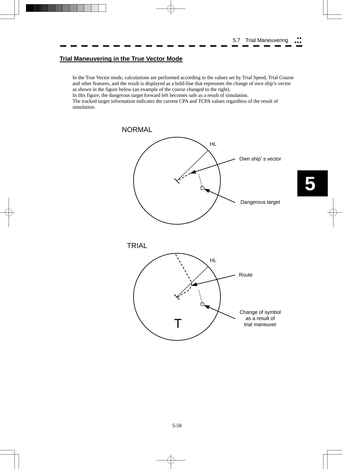
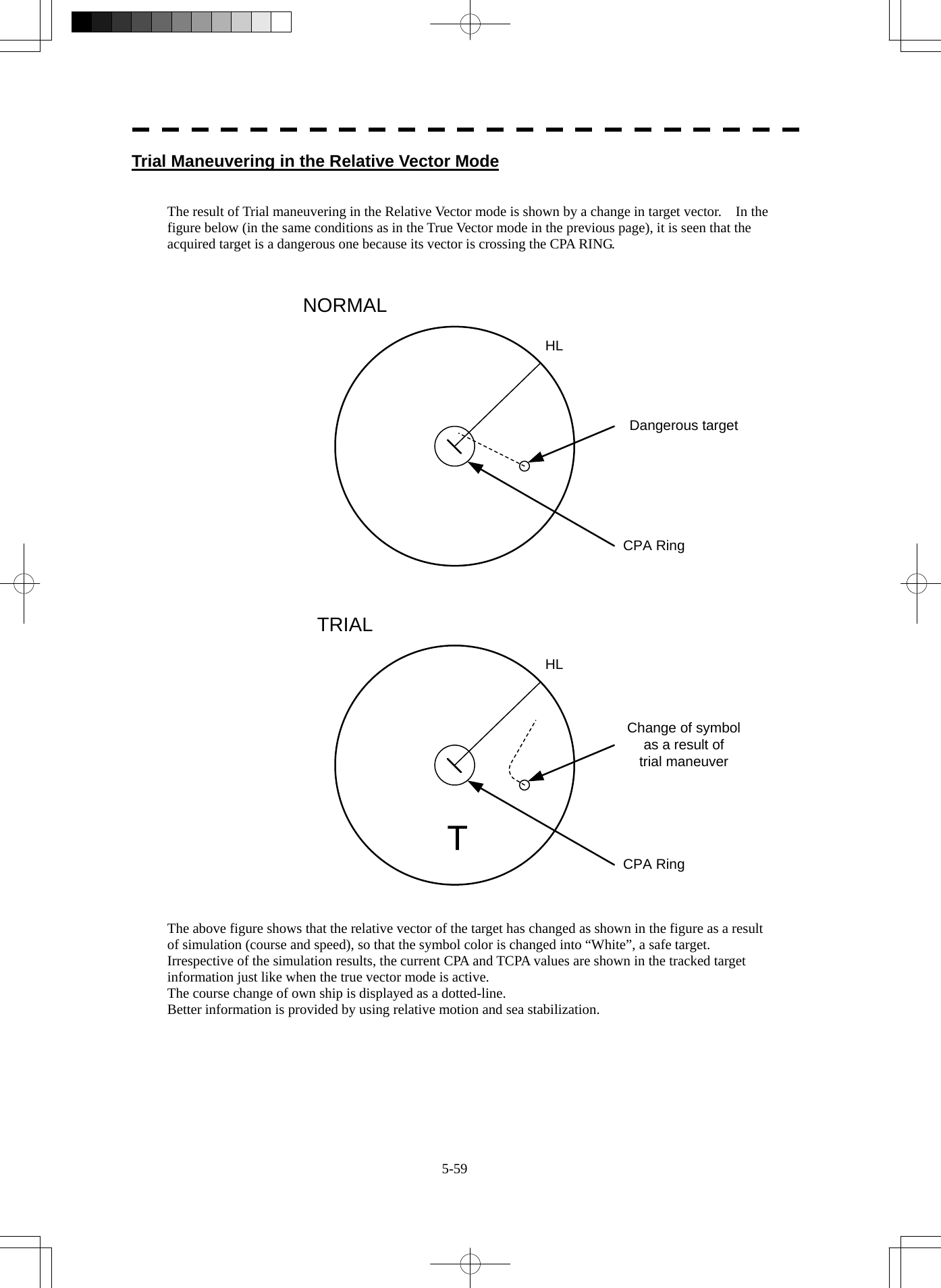
![5-60 5 5.7 Trial Maneuvering yyyyyOperation of Trial Maneuvering Function Procedures 1 Press the [TT MENU] key. 2 Open the Trial Maneuver menu by performing the following menu operation. 3. Trial Maneuver 3 Press the [1] key. The Trial Function will be set to on or off. On : The trial maneuvering function is turned on. Off : The trial maneuvering function is turned off. When the Trial Function is active, the character " T " will display at the bottom of the radar display. 4 Set values for Course by turning the [EBL] dial, and for Speed by turning the [VRM] dial. 5 Set other characteristics. Vector Time : Vector time (1 to 60 min) Time to Maneuver : Time until trial maneuvering is started (0 to 30 min) Own Ship Dynamic Trait> : Dynamic trait of the own ship → Reach : Range from when steered to when the ship beings to turn (0 to 2000 m) → Turn Radius : Turning radius (0.10 to 2.00 NM) → Acceleration : Acceleration (0.0 to 100 kn/min) → Deceleration : Deceleration (0.0 to 100 kn/min) For inputs to the value input screen, refer to Section 3.3.4. Dangerous target symbols are displayed in red and safe target symbols in white. * Vector Time is valid only when Trial Function is set to on. If it is off, the vector time before trial maneuvering is displayed. Time until the start of trial maneuvering is counted down immediately after the input. The acceleration and deceleration are influenced depending on the relationship between the current speed and the input speed for trial maneuvering. If 0.0 kn/min is set for Acceleration when the speed for trial maneuvering is faster than the current speed, or for Deceleration when the speed for trial maneuvering is slower than the current speed, the system performs simulation on the assumption that the speed is changed immediately after the time set for Time to Maneuver . Cancellation 1 Press the [1] key while the Trial Maneuver menu is displayed. The Trial Function will be set to on or off. Off : The trial maneuvering function is turned off.](https://usermanual.wiki/Japan-Radio/NKE2254.Users-Manual/User-Guide-1510215-Page-298.png)
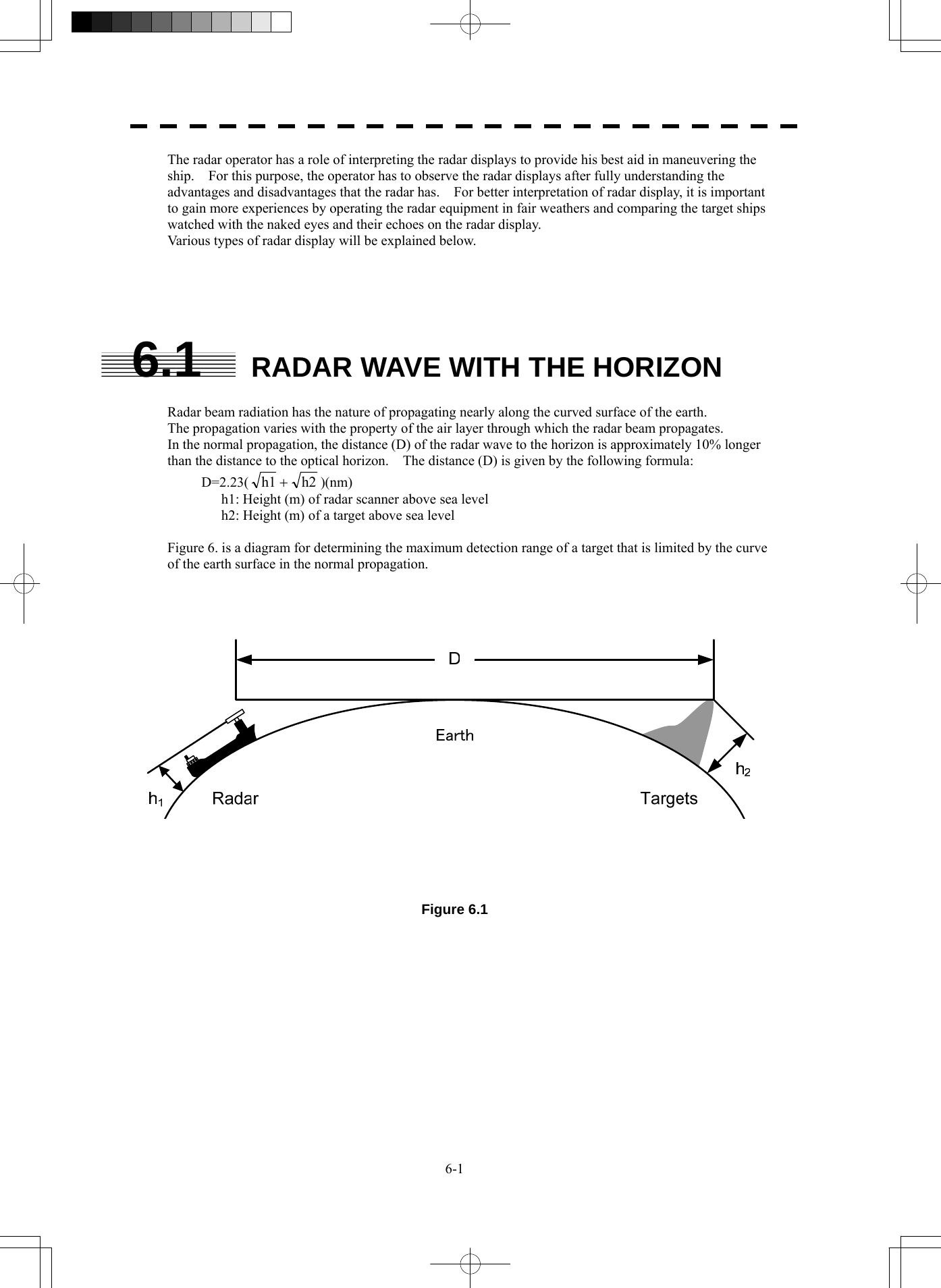

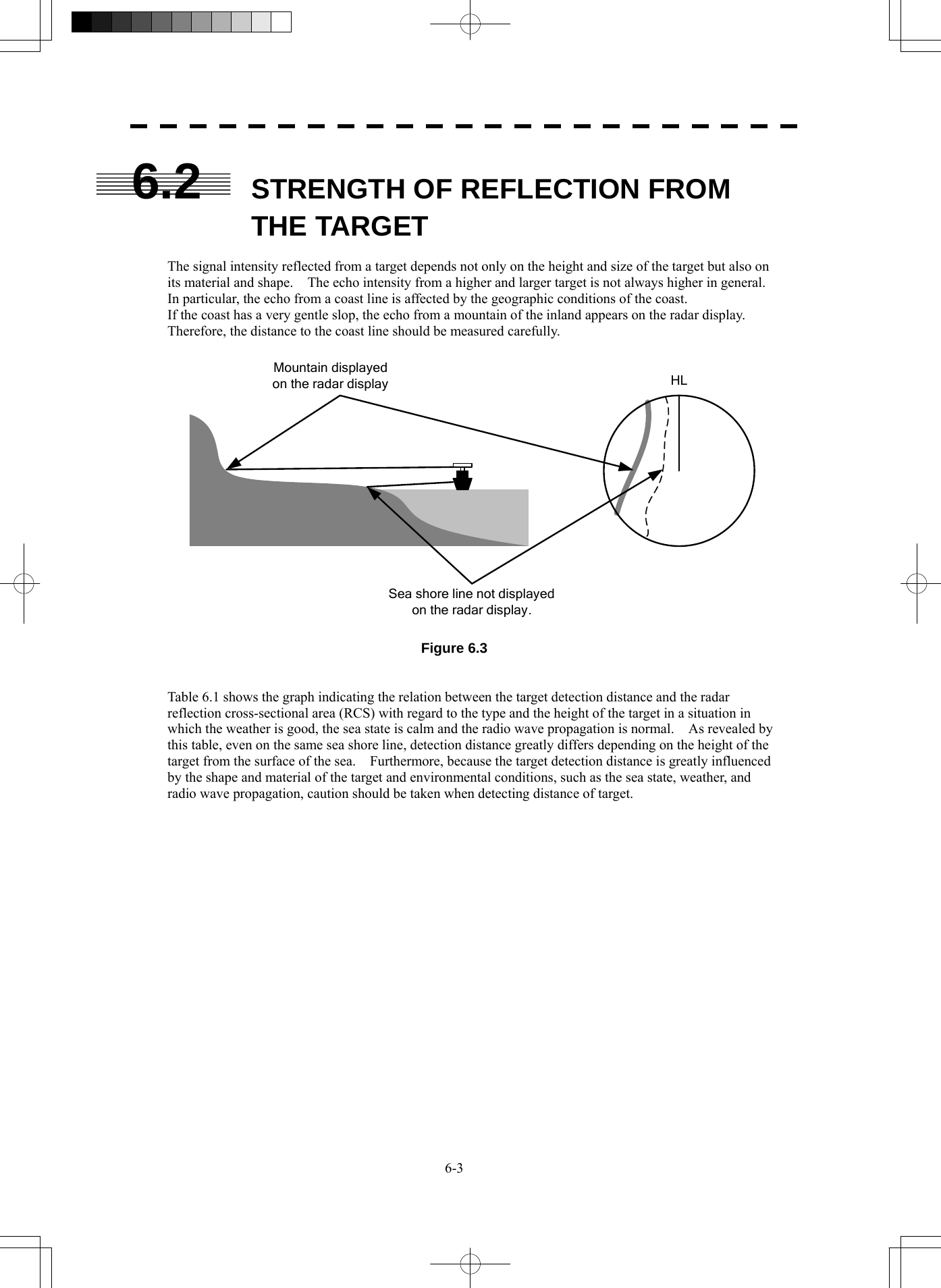
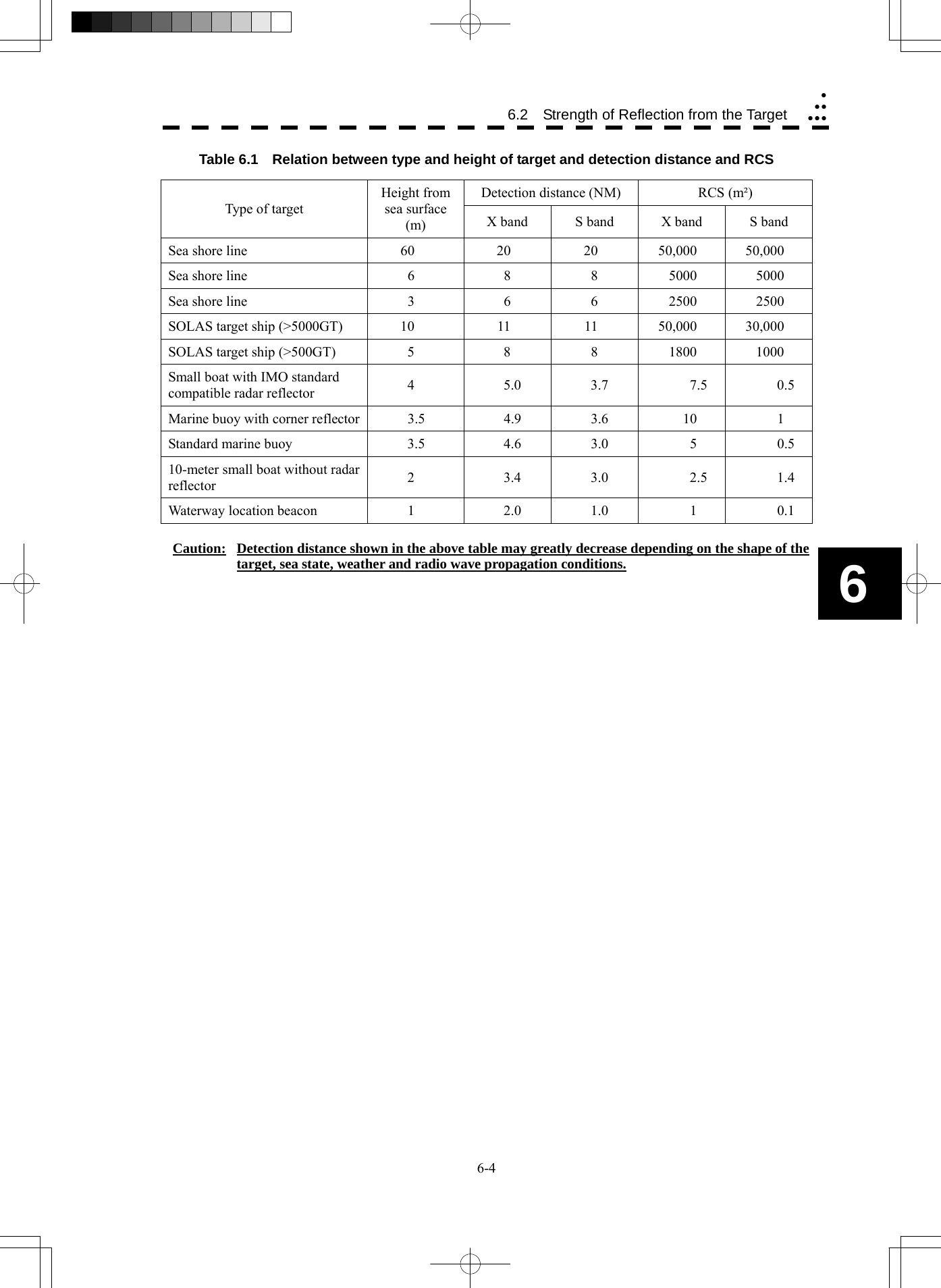
![6-5 6.3 SEA CLUTTER AND RAIN AND SNOW CLUTTER In addition to the echo required for observing ships and land radar video image also includes unnecessary echo, such as reflection from waves on the sea surface and reflection from rain and snow. Reflection from the sea surface is called "sea clutter," and reflection from rain and snow is called "rain and snow clutter," and those spurious waves must be eliminated by the clutter rejection function. [I] Sea clutter Sea clutter appears as an image radiating outwardly from the center of the radar display and changing depending on the size and the shape of waves. Generally, as waves become larger, image level of the sea clutter is intensified and the clutter far away is also displayed. When waves are large and the sea clutter level is high, it is difficult to distinguish sea clutter from a small boat whose reflection intensity is weak. Accordingly, it is necessary to properly adjust the sea clutter rejection function. Table 6.2 shows the relation between the sea state (SS) showing the size of waves generated by wind and the radar's detection probability. Table 6.2 Sea state and probability of target detection S band radar (probability to detect a target at a distance of 0.4 NM) X band radar (probability to detect a target at a distance of 0.7 NM) V: Detection probability of 80 % M: Detection probability of 50 % NV: Detection probability of less than 50 % RCS SS1 to 2 SS2 to 3 SS3 to 4 SS4 to 5 0.1m2 V V-M M-NV 0.5 m2 V V V-M M-NV 1 m2 V V V V-M RCS SS1 to 2 SS2 to 3 SS3 to 4 SS4 to 5 1m2 V-M M-NV 5 m2 V V-M M-NV 10 m2 V V V V-M](https://usermanual.wiki/Japan-Radio/NKE2254.Users-Manual/User-Guide-1510215-Page-305.png)
![6-6 6.3 Sea Clutter and Rain and Snow Clutteryyyyyy6 As shown in Table 6.3, the number of SS increases as the wind speed becomes high and the waves become large. Table 6.2 reveals that detection probability decreases from V (80 %) to NV (less than 50 %) as the number of SS increases. Therefore, even if the sea state is calm and a target clearly appears on the radar display, when the sea state becomes rough, target detection probability decreases resulting in difficulty of target detection by the radar. Table 6.3 Relation between Douglas sea state and average wind speed and significant wave height Significant wave height: an average of top N/3 higher waves when the number of waves detected within a constant time duration is N For example, in the case of a standard marine buoy, RCS of X band radar is 5 m2 as shown in Table 6.1. When observing such a target in the sea state (SS3) in which significant wave height exceeds 1.2 meters, detection probability is M-NV, as shown in Table 6.2, which indicates 50 % or less. [II] Rain and snow clutter Rain and snow clutter is a video image that appears in a location where rain or snow is falling. The image changes according to the amount of rain (or the amount of snowfall). As precipitation increases, the image of rain and snow clutter becomes intensified on the radar display, and in the case of localized heavy rain, an image similar to the image indicating land is displayed in some cases. Furthermore, because radio waves tend to attenuate due to rain and snow, the ability to detect a target in the rain and snow clutter or a target beyond the rain and snow clutter may decrease. The amount of attenuation depends on the transmission frequency, antenna beam width, and the pulse length. Figure 6.3 and Figure 6.4 show examples in which detection distance is reduced due to the influence of precipitation. Because of this, a target, which clearly appeared up to 10 NM by an X band radar (pulse width of 0.8 μs) when it was not raining, may become dimly visible up to 5 NM when the amount of rain becomes 4 millimeters per hour. Furthermore, when comparing the X band radar with the S band radar, target detection distance decreases less when an S band radar is used, which means it is influenced less by precipitation. Sea state Average wind speed (kn) Significant wave height (m) 0 <4 <0.2 1 5-7 0.6 2 7-11 0.9 3 12-16 1.2 4 17-19 2.0 5 20-25 3.0 6 26-33 4.0](https://usermanual.wiki/Japan-Radio/NKE2254.Users-Manual/User-Guide-1510215-Page-306.png)
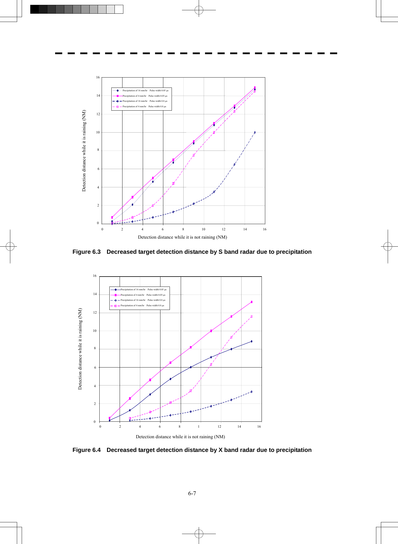
![6-8 6.3 Sea Clutter and Rain and Snow Clutteryyyyyy6 [III] Coping with sea clutter and rain and snow clutter When the weather is bad and the ocean is rough, the use of an S band radar is effective because the radar is not influenced by sea clutter so much and attenuation due to rain drops is small. When an X band radar is used, reducing the pulse width will reduce the influence by spurious waves, and also the spurious wave rejection function effectively works; therefore, the use of short pulse is effective when the weather is bad. By using image processing functions PROC 1 to 3, it is expected that spurious waves are further suppressed. Since optimal settings for those items can be automatically made by using the function mode, it is recommended that FUNC Storm or FUNC Rain be used by selecting the function mode when the weather is bad. For details of the function mode, see Chapter 3.9. However, these functions may make some targets invisible, particularly targets with higher speeds.](https://usermanual.wiki/Japan-Radio/NKE2254.Users-Manual/User-Guide-1510215-Page-308.png)
![6-9 6.4 FALSE ECHOES The radar observer may be embarrassed with some echoes that do not exist actually. These false echoes appear by the following causes that are well known: [I] Shadow When the radar scanner is installed near a funnel or mast, the echo of a target that exists in the direction of the funnel or mast cannot appear on the radar display because the radar beam is reflected on the funnel or mast. Whether there are some false echoes due to shadows can be checked monitoring the sea clutter returns, in which there may be a part of weak or no returns. Such shadows appear always in the same directions, which the operator should have in mind in radar operation. [II] Side Lobe Effect A broken-line circular arc may appear at the same range as the main lobe of the radar beam on the radar display. This type of false echo can easily be discriminated when a target echo appears isolated. (See Figure 6.5) HL Figure 6.5 [III] False Echo by Secondary Reflection When a target exists near own ship, two echoes from the single target may appear on the radar display. One of those echoes is the direct echo return from the target and the other is the secondary reflection return from a mast or funnel that stands in the same direction as shown in Figure 6.6. Radar scannerFunnelHLDirect microwaveSecondary reflectionof microwaveActual targetFalse echo from funnel Figure 6.6](https://usermanual.wiki/Japan-Radio/NKE2254.Users-Manual/User-Guide-1510215-Page-309.png)
![6-10 6.4 False Echoesyyyyyy6 [IV] False Echo by Multiple Reflection When there is a large structure or ship with a high vertical surface near own ship as shown in Figure 6.7, multiple refection returns may appear on the radar display. These echoes appear in the same intervals, of which the nearest echo is the true echo of the target. Figure 6.7 [V] Second Time Echoes The maximum radar detection range depends upon the height of the scanner and the height of a target as described in the section of “The Horizon for Radar Beam Radiation”. If a so-called “duct” occurs on the sea surface due to a certain weather condition, however, the radar beam may propagate to a abnormally long distance, at which a target may be detected by the radar. For instance, assuming that the pulse length is MP3 (on the repetition frequency of 1400 Hz), the first pulse is reflected from a target at about 58 NM or more and received during the next pulse repetition time. In this case, a false echo (second time echo) appears at a position that is about 58 NM shorter than the actual distance. If the false echo appears at 5 NM on the radar display, the true distance of the target is 5+58=63 NM. On the pulse length is SP1 (on the repetition frequency of 2250 Hz), a false echo may appear at a position that is about 36 NM shorter than the actual distance. This type of false echo can be discriminated by changing over the range scale (the repetition frequency), because the distance of the target changes accordingly. If second time echo is appeared, the use of Economy mode in PRF menu is effective. Otherwise, Stagger Trigger menu set to on. (See section 3.8.3)](https://usermanual.wiki/Japan-Radio/NKE2254.Users-Manual/User-Guide-1510215-Page-310.png)
![6-11 [VI] Radar Interference When another radar equipment using the same frequency band as that on own ship is near own ship, a radar interference pattern may appear on the radar display. This interference pattern consists of a number of spots which appear in various forms. In many cases, these spots do not always appear at the same places, so that they can be discriminated from the target echoes. (See Figure 6.8) HL HL Figure 6.8 If radar equipment causing an interference pattern and this radar are of the same model, their transmitting repetition frequency is nearly the same. As a result, interference patterns may be displayed concentrically. In this case, the interference patterns cannot be eliminated by using only the interference reflector function, so press [TX/PRF] key several times to fine-tune the transmitting repetition frequency. An interference suppressing effect can be heightened by applying a different transmitting repetition frequency to the interference pattern source radar and this radar.](https://usermanual.wiki/Japan-Radio/NKE2254.Users-Manual/User-Guide-1510215-Page-311.png)
![6-12 6 6.5 Display of Radar Transponderyyyyyy6.5 DISPLAY OF RADAR TRANSPONDER (SART) The SART (Search and rescue Radar Transponder) is a survival device authorized by the GMDSS (Global Maritime Distress and Safety System), which is used for locating survivors in case that a distress accident occurs at sea. The SART is designed to operate in the 9 GHz frequency band. When receiving the 9 GHz radar signal (interrogating signal) transmitted from the radar equipment on a rescue ship or search aircraft, the SART transmit a series of response signals to inform the distress position to the rescue and search party. * This radar provides a shortcut item to make settings for SART signal reception. Execution of this item automatically switches to the setting for SART reception. It also functions for detect the beacon or target enhancer. Procedures 1 Press [RANGE +] or [RANGE -] key to set the radar range to 6 NM or 12 NM. 2 Press [RADAR MENU] key twice, and then set the SART display mode according to the procedures below. 2. RADAR Menu → 1. Process Setting → 9. SART On : SART On Off : SART Off With the SART display mode set to ON, settings as shown below are made automatically. (1) Sea clutter control: Minimum (Most counterclockwise) (2) AUTO SEA function: Off (3) Rain and Snow Clutter Control (RAIN): minimum (4) Auto Rain and Snow Clutter function (AUTO RAIN): Off (5) TUNE control: No tuning (to weaken clutter echoes) (6) Interference rejecter (IR): Off (7) PROCESS: Off](https://usermanual.wiki/Japan-Radio/NKE2254.Users-Manual/User-Guide-1510215-Page-312.png)
![6-13 z When the SART function is set to ON, small targets around radar station will disappear from the radar display. z After end of detecting the START signal, turn the START display off. Then the radar returns to the normal mode. [Example of Display] Attention](https://usermanual.wiki/Japan-Radio/NKE2254.Users-Manual/User-Guide-1510215-Page-313.png)
![7-1 7.1 SETTINGS AT INSTALLATION This section describes the electrical adjustment procedures to be performed by service engineers during system installation. The bearing adjustment value is saved to non-volatile memory in the scanner. Other settings are saviedto non-volatile memory in the radar process unit. CAUTION Any adjustments must be made by specialized service personnel. Incorrect settings may result in unstable operation. Do not make any adjustments during operation. Failure to comply may result in adverse effects on the radar function which may lead to accidents or equipment failure. 7.1.1 How to Open the Serviceman Menu (Some items are not set on the JPL-600-MK2 for VTS.) Procedures 1. Press the [RADAR Menu] key for 2 seconds. The Code Input menu will appear. 2. Press [0] key. 3. Put the cursor on the ENT button, and press the [ENT] key. The Serviceman Menu will appear.](https://usermanual.wiki/Japan-Radio/NKE2254.Users-Manual/User-Guide-1510215-Page-316.png)
![7-2 7.1 Settings at Installation yyyyyyy7 7.1.2 GYRO I/F Setting (Not used on the JPL-600-MK2 for VTS) The GYRO I/F circuit of the system is designed to be compatible with most types of gyro compasses by simply setting the switches. Step motor type: 20 to 170 VDC Synchro-motor type: Primary excitation voltage 35 to 120 VAC Before power-on operation can be performed, the switches S1 to S5 on the GYRO I/F circuit (PC4201) must be set in accordance with the type of your gyro compass by performing the procedure below. The switches are factory-set for a gyration ratio of 180X and the step motor type. Make sure of the type of the gyro compass installed on the own ship before starting the procedure below. Procedures 1. Set S1 to "OFF." The gyro compass and GYRO I/F are turned off. 2. Set S2 and S3 in accordance with the type of your gyro compass. There are two types of gyro compasses: one type outputs a step signal, and the other type outputs a synchro signal. Make sure of the type of the gyro compass installed on the own ship before setting the switches S2 and S3. Synchro signal: Set the switches to [SYNC]. Step signal: Set the switches to [STEP]. 3. Set the DIP switch S4. The items to be set are listed below. For the settings, refer to Table 7-1. S4-1: LOG alarm ON/OFF S4-2: GYRO simulator ON/OFF S4-3: LOG simulator ON/OFF S4-5: Time before occurrence of GYRO alarm S4-6: Sensor to be used (GYRO/NMEA) S4-7/8: Baud rate when NMEA is used 4. Set the DIP switch S5. The items to be set are listed below. For the setting, refer to Table 7-2. S5-1: Type of gyro signal (step/synchro) S5-2/3: Gyration ratio of gyro compass S5-4: Gyration direction of gyro compass S5-5: Type of log signal (pulse/synchro) S5-7/8: Ratio of log signal 5. Connect the gyro signal and log signal cables to the terminal block. 6. Set S1 to "ON." The gyro compass and GYRO I/F are connected. 7. After power-on operation, set the true bearing according to Section 7.1.7. 8. Make sure of the radar video and the operation with the true bearing value. 9. If the true bearing value of the radar equipment is reversed, change the setting of the switch S5-4.](https://usermanual.wiki/Japan-Radio/NKE2254.Users-Manual/User-Guide-1510215-Page-317.png)
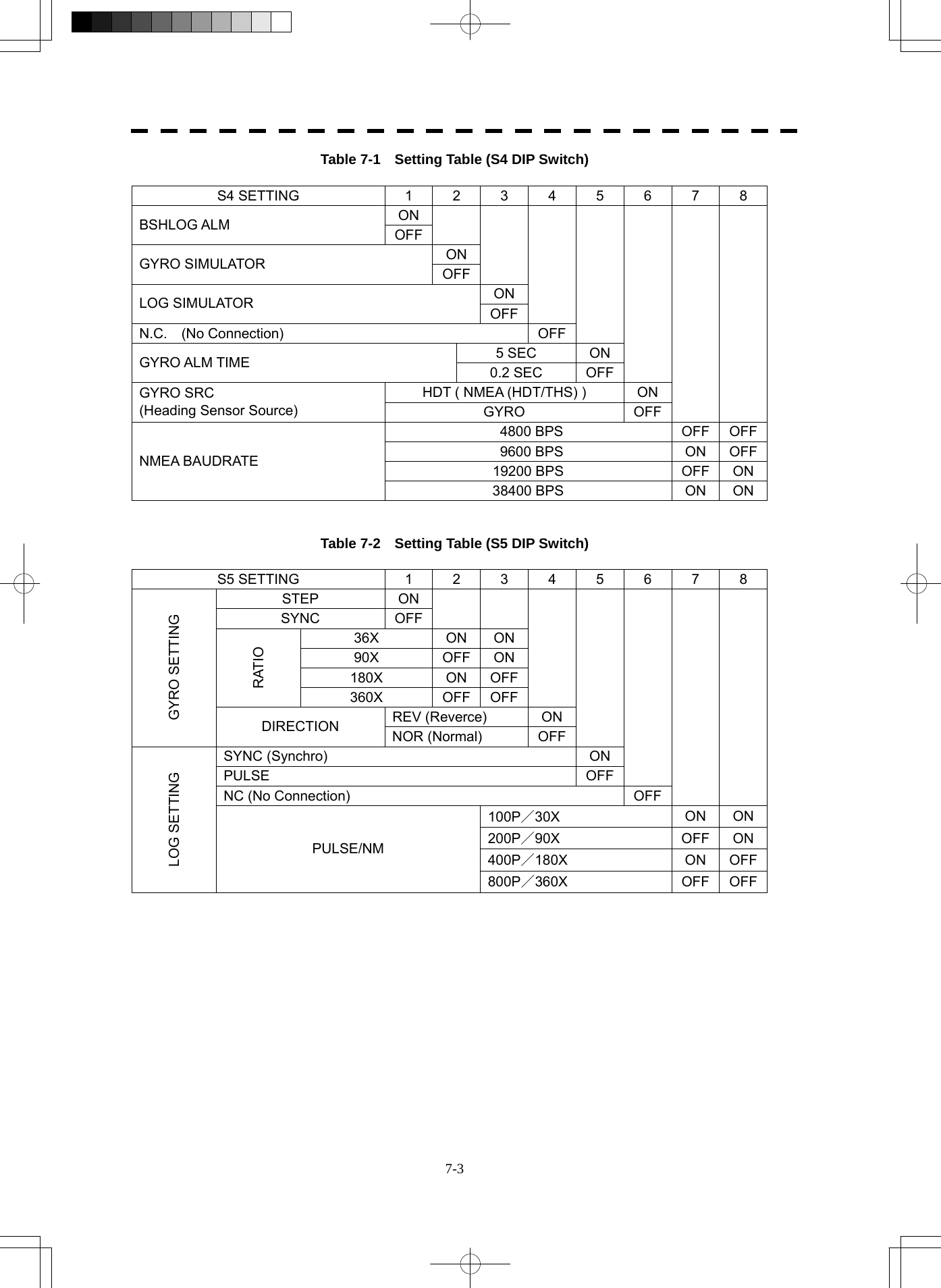
![7-4 7.1 Settings at Installation yyyyyyy7 7.1.3 Tuning (Tune Adjustment) Adjust the tuning control for the transmitter and receiver. The turning control should be adjusted when the system is installed or when the magnetron is replaced. Procedures 1. Set a range of 48 NM or more. 2. Open the Serviceman Menu. 3. Open the Tune Adjustment menu by performing the following menu operation. 1. Adjust Menu → 1. Tune Adjustment 4. Adjust the tune adjustment value so that the tune indicator bar at the upper left of the display is maximized. For how to input numeric data on the numeric value input screen, see Section 3.3.4. 5. Move the cursor onto the ENT button, and press the [ENT] key. [I] Tune Indicator Adjustment Set the scale mark when the tune indicator bar reaches the maximum point. Procedures 1. Set a range of 48 NM or more. 2. Open the Serviceman Menu. 3. Open the Tune Indicator Adjust menu by performing the following menu operation. 1. Adjust Menu → 4. TXRX Adjustment → 3. Tune Indicator Adjust 4. Adjust the tune indicator adjustment value so that the tune indicator bar at the upper left of the display reaches a point of 80 to 90% of the maximum. For how to input numeric data on the numeric value input screen, see Section 3.3.4. 5. Move the cursor onto the ENT button, and press the [ENT] key.](https://usermanual.wiki/Japan-Radio/NKE2254.Users-Manual/User-Guide-1510215-Page-319.png)
![7-5 • With the JPL-600-1ER2 radar: For this model, perform Tune Peak Adjustment explained below. After the above adjustment procedure, perform the adjustment procedures below. [II] Tune Peak Adjustment Adjust the tune indicator and echo peak. Procedures 1. Set a range of 48 NM or more. 2. Open the Serviceman Menu. 3. Open the Tune Peak Adjustment menu by performing the following menu operation. 1. Adjust Menu → 4. TXRX Adjustment → 2. Tune Peak Adjustment 4. Adjust the tune peak adjustment value so that the tune indicator bar at the upper left of the display is maximized. For how to input numeric data on the numeric value input screen, see Section 3.3.4. 5. Move the cursor onto the ENT button, and press the [ENT] key. 7.1.4 Bearing Adjustment Make adjustment so that the bearing of the target measured with the compass matches the bearing of the target echo on the radar display. Procedures 1. Select H Up for the bearing presentation. Set video processing (PROC) to OFF. 2. Measure the bearing of an appropriate target object (e.g., a ship at anchor, a breakwater, or a buoy) relative to the scanner heading line. 3. Open the Serviceman Menu. 4. Open the Bearing Adjustment menu by performing the following menu operation. 1. Adjust Menu → 2. Bearing Adjustment 5. Adjust the bearing adjustment value so that the target measured in step 2 is adjusted to the correct bearing. For how to input numeric data on the numeric value input screen, see Section 3.3.4. Make adjustment by the 0.1°. 6. Move the cursor onto the ENT button, and press the [ENT] key.](https://usermanual.wiki/Japan-Radio/NKE2254.Users-Manual/User-Guide-1510215-Page-320.png)
![7-6 7.1 Settings at Installation yyyyyyy7 7.1.5 Range Adjustment Make adjustment so that the range of a target on the radar display is shown correctly. Procedures 1. Search the radar display for a target of which range is already known. 2. Open the Serviceman Menu. 3. Open the Range Adjustment menu by performing the following menu operation. 1. Adjust Menu → 3. Range Adjustment 4. Adjust the range adjustment value so that the target measured in step 1 is adjusted to the correct range. (For inputs to the value input screen, refer to Section 3.3.4.) 5. Move the cursor onto the ENT button, and press the [ENT] key. 7.1.6 Navigator Setting (Device) (Not used on the JPL-600-MK2 for VTS) Determine whether to connect navigators to the radar equipment. Only the navigators set to ON here can be used. Procedures 1. Open the Serviceman Menu. 2. Open the Device Installation menu by performing the following menu operation. 2. Installation Menu → 9. Next → 3. Device Installation 3. Select On for navigators connected to the radar equipment, and Off for navigators not connected. GYRO : Gyro (via GYRO I/F) Compass : Compass (Compliant with IEC61162) GPS Compass : GPS compass produced by JRC Log : Log (via GYRO I/F) 2AXW : 2-axis log (Speed over water: Compliant with IEC61162) 2AXG : 2-axis log (Speed over ground: Compliant with IEC61162) GPS : GPS (Compliant with IEC61162)](https://usermanual.wiki/Japan-Radio/NKE2254.Users-Manual/User-Guide-1510215-Page-321.png)
![7-7 7.1.7 Setting of True Bearing Value (Not used on the JPL-600-MK2 for VTS) If GYRO I/F is used to input a gyro signal, the true bearing value indicated by the master gyro does not match the value indicated by the radar equipment only in a rare case. In this case, perform the following procedure to adjust the true bearing value of the radar equipment to the value of the master gyro. Procedures 1. Press the [RADAR MENU] key twice. 2. Open the GYRO Setting menu by performing the following menu operation. 4. NAV Equipment Setting → 1. GYRO Setting 3. Input the master gyro value to the value input screen. (For inputs to the value input screen, refer to Section 3.3.4.) 4. Move the cursor onto the ENT button, and press the [ENT] key. 7.1.8 Antenna Height Setting (Antenna Height) Set the height of radar antenna above sea level. Do not change this setting carelessly. Procedures 1. Measure the height of radar antenna above sea level in advance. 2. Open the Serviceman Menu. 3. Open the Antenna Height menu by performing the following menu operation. 1. Adjust Menu → 4. TXRX Adjustment → 1. Antenna Height 4. Select the setting that matches the antenna height measured in step 1.](https://usermanual.wiki/Japan-Radio/NKE2254.Users-Manual/User-Guide-1510215-Page-322.png)
![7-8 7.1 Settings at Installation yyyyyyy7 7.1.9 Setting of CCRP/Antenna/GPS Antenna Position (CCRP Setting) Set the radar station CCRP location, radar antenna installation location, and GPS installation location. CCRP : Up to four locations can be input. (One location selected when used) Radar antenna : Up to eight radar antennas can be input. (Automatically selected in response to ISW operation) GPS : Up to four locations can be input. (One location selected when used) Procedures 1. Measure the CCRP location, radar antenna location, and GPS antenna location in advance. 2. Open the Serviceman Menu. 3. Open the CCRP Setting menu by performing the following menu operation. 2. Installation Menu → 4. CCRP Setting 4. Specify the ship length for Length at the upper right of the CCRP Setting Menu, and the ship width for Beam. 5. Move the cursor onto the CCRP1 X, Y value, and press the ENT key to input the CCRP1 location. When X > 0, the CCRP is on the starboard side of the ship. When X < 0, it is on the port side. 6. To input the second CCRP, press the CCRP2 button to display the CCRP2 X,Y value, and input the value in the same manner for step 5. Similarly, input the third and subsequent CCRPs. 7. Repeat the above steps to input the GPS location(s) and radar antenna location(s). 8. If multiple CCRP locations and GPS locations are input, select the CCRP location and GPS location to be used by pressing the buttons at the upper left of the menu. 9. Press [0] key to close the CCRP Setting menu.](https://usermanual.wiki/Japan-Radio/NKE2254.Users-Manual/User-Guide-1510215-Page-323.png)
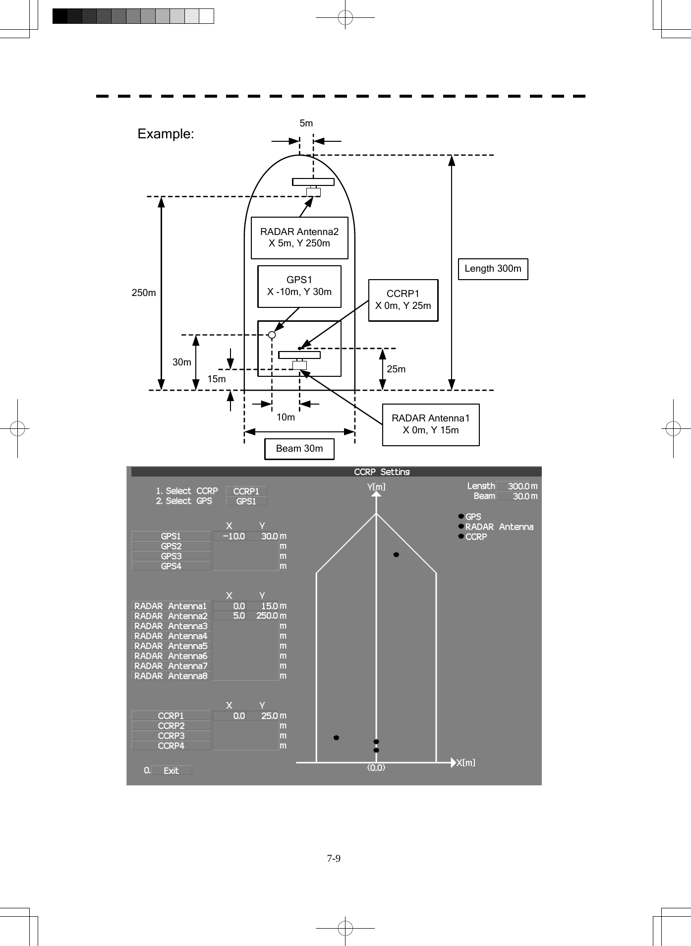
![7-10 7.2 Settings yyyyyyy7 7.2 SETTINGS This section describes the electrical adjustment procedures to be performed by service engineers during system installation. CAUTION Any adjustments must be made by specialized service personnel. Incorrect settings may result in unstable operation. Do not make any adjustments during operation. Failure to comply may result in adverse effects on the radar function which may lead to accidents or equipment failure. 7.2.1 Communication Port Setting (COM Port Setting) External sensor signals are input to the radar equipment through a communication port. The radar equipment has five communication ports. For signals to be input from sensors or to be output to the sensors, communication ports need to be set in accordance with the sensors. [I] Baud Rate Setting Set the baud rate of the signal to be input to the COM port. Procedures 1. Open the Serviceman Menu. 2. Open the Baud Rate menu by performing the following menu operation. 2. Installation Menu → 5. COM Port Setting → 1. Baud Rate](https://usermanual.wiki/Japan-Radio/NKE2254.Users-Manual/User-Guide-1510215-Page-325.png)
![7-11 3. Set the baud rate of the port to be set. Selection value 1. COMPASS : 4800(NMEA)/9600(NSK)/38400(Fast NMEA) bps 2. NAV1 : 1200/4800/9600/38400 bps 3. NAV2 : 1200/4800/9600/38400 bps 4. GPS : 1200/4800/9600/38400 bps 5. NMEA : 1200/4800/9600/38400/115200 bps The bold values are factory-set. The COMPASS port is a receive-only port that is dedicated to COMPASS signals. [II] Reception Port Setting (RX Port) Set the numbers of ports for receiving signals from sensors. There are two methods for receiving signals: specifying a port for each sensor, or using the automatic recognition function without specifying ports. Procedures 1. Open the Serviceman Menu. 2. Open the RX Port menu by performing the following menu operation. 2. Installation Menu → 5. COM Port Setting → 2. RX Port 3. Set a port for each sensor. Settable sensor signals GPS, DLOG, Alarm, Depth, Temperature, Wind, Current, ROT, RSA Selectable ports When the automatic recognition function is used: AUTO When ports are specified: NAV1, NAV2, GPS, and NMEA](https://usermanual.wiki/Japan-Radio/NKE2254.Users-Manual/User-Guide-1510215-Page-326.png)
![7-12 7.2 Settings yyyyyyy7 [III] Reception Sentence Setting (RX Sentence) Set signal sentences to be received from sensors. The system is factory-set for using all sentences. To receive only specified sentences, select No Use for sentences which are not necessary. Procedures 1. Open the Serviceman Menu. 2. Open the RX Sentence menu by performing the following menu operation. 2. Installation Menu → 5. COM Port Setting → 3. RX Sentence 3. Select the sentences to be used by the sensors to be set. Selection value: (Use) or (No Use) can be set for each sentence. 1. GPS(LL/COG/SOG) : GGA/RMC/RMA/GNS/GLL/VTG 2. GPS(WPT/Time) : GGA/RMC/RMB/BWC/BWR/ZDA 3. Depth : DPT/DBK/DBT/DBS 4. Wind : MWV/MWD 5. Current : Data Set Number : 0-9. Set the number of the sentence to be used by Data Set Number. (Initial value All) Layer A : 0-999. Set the number of the sentence to be used with layer A by Layer Number. (Initial value 3) Layer B : 0-999. Set the number of the sentence to be used with layer B by Layer Number. (Initial value 4) Layer C : 0-999. Set the number of the sentence to be used with layer C by Layer Number. (Initial value 5)](https://usermanual.wiki/Japan-Radio/NKE2254.Users-Manual/User-Guide-1510215-Page-327.png)
![7-13 [IV] Transmission Port Setting (TX Port) For each sentence, set a communication port through which signals are transmitted to sensors. Procedures 1. Open the Serviceman Menu. 2. Open the TX Port menu by performing the following menu operation. 2. Installation Menu → 5. COM Port Setting → 4. TX Port 3. Select the communication port through which the sentence to be set is output. Settable sentences TTM(TT), TLL(TT), TTD(TT), TLB(TT), OSD, RSD, ALR, ACK, TTM(AIS), TLL(AIS), TTD(AIS), TLB(AIS), RemoteMaintenance, JRC-ARPA, APB, BOD, GGA, GLL, RMC, RMB, VTG, XTE, BWC, HDT, THS Selectable ports NAV1, ARPA, GPS, and NMEA 4. Select the output format, talker, and transmission interval. Signals for which the above items can be set: • NMEA0183 Output Format Signal names: APB, BOD, GGA, GLL, RMC, RMB,VTG, XTE, BWC, HDT, THS Selection Value: V1.5, V2.0, and V2.3 • NMEA0183 Talker Signal names: APB, BOD,RMB, XTE, BWC, HDT, THS Selection Value: Standard: The talker is RA. GP: The talker is GP. For TTM, TLL, TTD, TLB, OSD, RSD and ALR the talker is always RA. For GGA, GLL, RMC, and VTG, the talker is always GP. • NMEA0183 TX Interval Signal names: APB, BOD, GGA, GLL, RMC, RMB,VTG, XTE, BWC, HDT, THS Selection Value: Set an interval in the range 1 to 9 seconds.](https://usermanual.wiki/Japan-Radio/NKE2254.Users-Manual/User-Guide-1510215-Page-328.png)
![7-14 7.2 Settings yyyyyyy7 [V] GPS Receive Port Setting (Select NAV Equipment) Select the receive port of GPS data. Procedures 1. Open the Serviceman Menu. 2. Open the COM Port setting menu by performing the following menu operation. 2. Installation Menu → 5. COM Port Setting 3. Press the [5] key. Units of Select NAV Equipment are switched. Internal GPS : The receive port is selected GPS connector of processor unit (JRC’s GPS). External GPS : The receive port is selected GPS terminal of terminal board circuit. 7.2.2 Sector Blank Setting (Sector Blank) In order not to display radar echoes, set a sector and stop transmission in the bearing. Three sector blank areas can be created. The sector blank function operates in the relative bearing with the bow. [I] Sector Blank Function On/Off (Sectors 1, 2, and 3) Procedures 1. Open the Serviceman Menu. 2. Open the Sector Blank menu by performing the following menu operation. 2. Installation Menu → 3. Sector Blank 3. Set the sector blank number Sector 1 , 2 , or 3 with which the sector blank function operates. The system allows the use of up to three sector blank areas. Set each sector blank area to on or off. On : The sector blank function is operated. Off : The sector blank function is stopped.](https://usermanual.wiki/Japan-Radio/NKE2254.Users-Manual/User-Guide-1510215-Page-329.png)
![7-15 [II] Sector Blank Area Creation (Make Sectors 1, 2, and 3) Procedures 1. Transmit the radar. 2. Open the Serviceman Menu. 3. Open the Sector Blank menu by performing the following menu operation. 2. Installation Menu → 3. Sector Blank 4. Press numeric keys corresponding to the desired sector creation Make Sector 1 , 2 , or 3 . The selected sector blank will be made. 5. Set the starting bearing of the sector blank by operating the [EBL] dial, and press the [ENT] key. 6. Set the ending azimuth of the sector blank by operating the [EBL] dial, and press the [ENT] key. 7.2.3 TNI Blank Setting (TNI Blank) Set a sector and stop tuning operation in the bearing. If a structure such as the mast is close to the radar antenna, automatic tuning operation may become unstable. In this case, set a TNI blank in the direction of the structure in order to stabilize the tuning operation. Only one TNI blank sector can be created. The TNI blank function operates in the relative bearing with the scanner heading line as the benchmark. [I] TNI Blank Function On/Off (Sector) Procedures 1. Open the Serviceman Menu. 2. Open the TNI Blank menu by performing the following menu operation. 2. Installation Menu → 9. Next → 2. TNI Blank 3. Select the item 1. TNI Blank in the menu, and turn on or off the TNI blank function. On : The TNI blank function is operated. Off : The TNI blank function is stopped.](https://usermanual.wiki/Japan-Radio/NKE2254.Users-Manual/User-Guide-1510215-Page-330.png)
![7-16 7.2 Settings yyyyyyy7 [II] TNI Blank Area Creation (Make Sector) Procedures 1. Transmit the radar. 2. Open the Serviceman Menu. 3. Open the TNI Blank menu by performing the following menu operation. 2. Installation Menu → 9. Next → 2. TNI Blank 4. Press the 2. Make Sector button in the menu. 5. Set the starting bearing of the TNI blank by operating the [EBL] dial, and press the [ENT] key. 6. Set the ending bearing of the TNI blank by operating the [EBL] dial, and press the [ENT] key. 7.2.4 Setting of Bearing Pulses from Antenna (Output Pulse) Set the output value of bearing pulses from the antenna. The system can set 2048 pulses or 4096 pulses. This setting is enabled only when an antenna of 25 or 30 kW is used. Procedures 1. Open the Serviceman Menu. 2. Open the Output Pulse menu by performing the following menu operation. 1. Adjust Menu → 4. TXRX Adjustment → 6. Output Pulse 3. Set the number of pulses to be output by the antenna. 2048 : 2048 pulses per antenna rotation (Recommended value) 4096 : 4096 pulses per antenna rotation * If a 10 kW antenna is used, 2048 is always set.](https://usermanual.wiki/Japan-Radio/NKE2254.Users-Manual/User-Guide-1510215-Page-331.png)
![7-17 7.2.5 Slave Mode Setting (Master/Slave) Place the system in the Slave mode when it is to be operated as the sub-display that displays radar echoes by using radar signals from other radar equipment. The input value of externally input bearing pulses can be set. The system can set 2048 pulses or 4096 pulses. [I] Slave Mode Setting (Master/Slave) Procedures 1. Open the Serviceman Menu. 2. Open the Installation Menu by performing the following menu operation. 2. Installation Menu 3. Select Slave for the item 2. Master/Slave in the menu. Master : The system operates as radar equipment while the own antenna is connected. Slave : The system operates as a sub-display while the signal cable of other radar equipment is connected. [II] Setting of Input Bearing Pulse (Input BP Count) Procedures 1. Open the Serviceman Menu. 2. Open the second page of the Installation Menu by performing the following menu operation. 2. Installation Menu → 9. Next 3. Set the number of pulses for the item 1. Input BP Count in the menu. 2048 : 2048 pulses per antenna rotation 4096 : 4096 pulses per antenna rotation](https://usermanual.wiki/Japan-Radio/NKE2254.Users-Manual/User-Guide-1510215-Page-332.png)
![7-18 7.2 Settings yyyyyyy7 7.2.6 Language Setting (Language) The system is designed to switch between display languages, Japanese and English. Procedures 1. Open the Serviceman Menu. 2. Open the Language menu by performing the following menu operation. 2. Installation Menu → 8. Language 3. Select the language to be used. 1. English 2. Japanese 3. Other 3. Other is an option to display character strings created by our agents. Ask the agent or our sales department if your language is supported. 4. To determine the selected language, turn the radar off, and then turn it on. 7.2.7 Date Time Setting To display time, the local time, local date, and time-zone difference must be set. However, if the "ZDA" sentence of NMEA0183 is received, time can be automatically displayed. Procedures 1. Press the [RADAR MENU] key twice. 2. Open the Date/Time Setting menu by performing the following menu operation. 5. Sub Menu → 6. Date/Time Setting](https://usermanual.wiki/Japan-Radio/NKE2254.Users-Manual/User-Guide-1510215-Page-333.png)
![7-19 2. Set information about date and time. [1] UTC/LMT (Time display system) UTC : Universal Time Coordinate LMT : Local Mean Time [2] LMT Date Input the date in local time. [3] LMT Time Input the time in local time. [4] Time Zone Input the time-zone difference between the universal time and local time. [5] Display Style Set one of the following date display formats. YYYY-MM-DD : Example: 2007-12-31 MMM DD, YYYY : Example: Dec 31, 2007 DD MMM YYYY : Example: 31 Dec 2007 [6] Synchronize with GPS A ZDA sentence sent by the GPS is used, thereby displaying time synchronized with the GPS time. On : Time synchronized with the GPS time Off : Time not synchronized with the GPS time * If On is selected for this item but a ZDA sentence is not input, the system internal clock function is used to display the date and time. 7.2.8 Input Installation Information The system can input installation information. Procedures 1. Open the Serviceman Menu. 2. Open the Installation Information menu by performing the following menu operation. 2. Installation Menu → 1. Installation Information 3. Input the installation information. For the input method on the numeric value and character input screens, see Section 3.3.4. [1] Date Input the date of installed system. [2] Name Input the name of installation personel. [3] Company Input the name of radar installer.](https://usermanual.wiki/Japan-Radio/NKE2254.Users-Manual/User-Guide-1510215-Page-334.png)
![7-20 7.2 Settings yyyyyyy7 7.2.9 Setting the Alarm System Setting the relay output (Relay Output) This function enables the control of ARPAALM terminal (on the terminal board circuit). Procedures 1. Open the Serviceman Menu. 2. Open the Relay Output menu by performing the following menu operation. 2. Installation Menu → 6. Alarm System → 2. Relay Output 3. Press the [1] key. The Relay Output mode is switched. Continuous : The output is continuously controlled. Intermittent : The output is intermittenly controlled. 4. Press the [numeric] key corresponding to the item to be changed. The item can be turned on / off. On : The relay output is turned on when alarm have issued. Off : The relay output is not turned on when alarm have issued. 2. TT CPA/TCPA : There is a dangerous target. (tracked target) 3. AIS CPA/TCPA : There is a dangerous target. (AIS target) 4. New Target : A new target is acquired in the automatic acquisition zone. 5. Lost : There is a lost target. (Target Tracking / AIS). 6. RADAR Alarm : Targets have entered the radar alarm range. Setting the ALR output (ALR Output) This function enables the control of ALR port (See the section 7.2.1). Procedures 1. Open the Serviceman Menu. 2. Open theALR output menu by performing the following menu operation. 2. Installation Menu → 6. Alarm System → 3. ALR Output 3. Press the [numeric] key corresponding to the item to be changed. The item is turned on / off. On : The ALR sentence is output when alarm have issued. Off : The ALR sentence is not output when alarm have issued. 1. System Alarm : The internal alarm. 2. TT/AIS Alarm : Target Tracking Alarms and AIS Function Alarms.](https://usermanual.wiki/Japan-Radio/NKE2254.Users-Manual/User-Guide-1510215-Page-335.png)
![7-21 Setting the External Acknowledgement (External ACK Setting) This function enables the control of system when ACK sentence have received. Procedures 1. Open the Serviceman Menu. 2. Open the External ACK Setting menu by performing the following menu operation. 2. Installation Menu → 6. Alarm System → 5. External ACK Setting 3. Press the [numeric] key corresponding to the menu to be changed. Critical Alarm :CPA/TCPA alarm. Normal Alarm :Exept Critical Alarm. 4. Press the [numeric] key corresponding to the item to be changed. The item is switched. Audio : Setting of alarm sound. On : The alarm sound is not stopped when acknowridgement have received. Off : The alarm sound is stopped when acknowridgement have received. Indication : Setting of alarm indication. Lighting : The alarm indication brinking is stopped when acknowridgement have received. Brinking : The alarm indication brinking is not stopped when acknowridgement have received. Acknowridge State : Setting of ALR sentence. A:ACK : Add acknowridgement to ALR sentence. V:UNACK : Add no acknowridgement (unrecognized) to ALR sentence.](https://usermanual.wiki/Japan-Radio/NKE2254.Users-Manual/User-Guide-1510215-Page-336.png)
![7-22 7.3 Adjustment yyyyyyy7 7.3 ADJUSTMENT This section describes the electrical adjustment procedures to be performed by service engineers during system installation. CAUTION Any adjustments must be made by specialized service personnel. Incorrect settings may result in unstable operation. Do not make any adjustments during operation. Failure to comply may result in adverse effects on the radar function which may lead to accidents or equipment failure. 7.3.1 Noise Level Adjustment (Noise Level) [I] Noise Level Adjustment for Signal Processing Procedures 1. Open the Serviceman Menu. 2. Open the Echo Noise Level menu by performing the following menu operation. 9. SP/TT Initial Setup → 1. Signal Processing → 1. Echo Noise Level 3. Increase/decrease the noise level adjustment value. The noise level is factory-set. After system installation, a great change in the noise level adjustment value should be avoided; it should be fine adjusted within ±5.](https://usermanual.wiki/Japan-Radio/NKE2254.Users-Manual/User-Guide-1510215-Page-337.png)
![7-23 [II] Noise Level Adjustment Mode (Setting Mode) A noise level is factory-adjusted while this mode is turned on. Procedures 1. Open the Serviceman Menu. 2. Open the Signal Processing menu by performing the following menu operation. 9. SP/TT Initial Setup → 1. Signal Processing 3. Press the [2] key. The noise level setting mode is switched between on and off. Factory-adjustment method • The GAIN control is set to the maximum position, the SEA control is set to the minimum position, the RAIN control is set to the minimum position, and IR, AUTO-SEA, AUTO-RAIN, PROC, FUNC, and TRAILS are all set to off. • The noise level adjustment mode is turned on. • While the noise level adjustment value is decreased gradually, the value with which radar echoes no longer appear is determined as the set value. • Ten is added to the set value (with which radar echoes no longer appear), and the result is set as the final noise level adjustment value. • The noise level adjustment mode is turned off when the adjustment is finished.](https://usermanual.wiki/Japan-Radio/NKE2254.Users-Manual/User-Guide-1510215-Page-338.png)
![7-24 7.3 Adjustment yyyyyyy7 z Do not change the set value carelessly. The vector constant shall be set to 4 normally. If the vector constant value is higher, a target’s vector will be better followed up when the target and own ship change their course or speed, but the vector accuracy will be lower on the contrary. 7.3.2 Adjustment of Target Tracking Function (TT) CAUTION Optimal values have been set for Video Level and Vector Constant; therefore, never change their values unless absolutely necessary. Failure to comply may result in accidents that would lower target tracking performance. [I] Vector Constant Adjustment (Vector Constant) Adjust the vector follow-up performance of the target tracking function. The vector constant is adjusted to an optimal value, so do not change it carelessly. Procedures 1. Open the Serviceman Menu. 2. Open the Vector Constant menu by performing the following menu operation. 9. SP/TT Initial Setup → 2. TT → 1. Vector Constant 3. Input the value to be set. To improve vector follow-up performance, increase the set value. To stabilize vectors, decrease the set value. Attention](https://usermanual.wiki/Japan-Radio/NKE2254.Users-Manual/User-Guide-1510215-Page-339.png)
![7-25 [II] Quantization Level Adjustment (Video Level) Use the target tracking function (TT) to adjust the level of the signal to be recognized as a target. If a small value is set, even weak target signals will be input to the target detection circuit of the target tracking function. However, many unnecessary signals are also input, which may cause unstable target acquisition or tracking. It is important to set a value four or five greater than the value with which unnecessary signals are detected. The quantization level is adjusted to an optimal value, so do not change it carelessly. CAUTION Do not change the quantization level settings unless absolutely necessary. If set at an inappropriate value, the target acquisition or target tracking function deteriorates, and this may lead to accidents. Procedures 1. Open the Serviceman Menu. 2. Open the TT (Target Tracking) menu by performing the following menu operation. 9. SP/TT Initial Setup → 2. TT 3. To change the quantization level of the automatic acquisition area, specify the item 2. Video TD Level in the menu. To change the quantization level of tracking and manual acquisition, specify the item 3. Video High Level .](https://usermanual.wiki/Japan-Radio/NKE2254.Users-Manual/User-Guide-1510215-Page-340.png)
![7-26 7.3 Adjustment yyyyyyy7 [III] Gate Size Adjustment (Gate Size) Use the target tracking function (TT) to set a target search area. The gate size is adjusted to an optimal value, so do not change it carelessly. Procedures 1. Open the Serviceman Menu. 2. Open the Gate Size menu by performing the following menu operation. 9. SP/TT Initial Setup → 2. TT → 5. Gate Size 3. Select a gate size. Wide : Large gate size Normal : Medium gate size Narrow : Small gate size [IV] CPA Limit Ring Display On/Off (Limit Ring) Use the target tracking function (TT) to determine whether to display the CPA limit for determining a dangerous ship. When the CPA limit ring display function is turned on and a relative vector is used, the CPA limit ring is displayed as a red circle. Procedures 1. Open the Serviceman Menu. 2. Open the TT (Target Tracking) menu by performing the following menu operation. 9. SP/TT Initial Setup → 2. TT 3. Press the [6] key. The Limit Ring item is turned on / off. Off : Limit ring not displayed On : Limit ring displayed](https://usermanual.wiki/Japan-Radio/NKE2254.Users-Manual/User-Guide-1510215-Page-341.png)
![7-27 7.3.3 Main Bang Suppression Adjustment (MBS) Main Bang Suppression is adjusted to suppress main bang, a reflection signal from 3D circuit including wave guide tube, that generally appears as a circular video focusing on the center of the radar display. Optimum adjustment allows main bang video to remain slightly on the display. WARNING Do not change MBS Level/Area unless absolutely necessary. Incorrect adjustment will result in deletion of nearby target images. Procedures 1. Open the Serviceman Menu. 2. Open the MBS menu by performing the following menu operation. 9. SP/TT Initial Setup → 3. MBS 3. Set the radar as follows: • Set the radar video enhance function and video processing (PROC) to OFF. • Turn the [RAIN] control to the minimum position (fully to the left). • Turn the [GAIN] control to the maximum position (fully to the right). • Turn the [SEA] control to achieve the strength with which main bang can be judged. 4. Set 20 for 2. MBS Area . 5. Adjust the value set for 1. MBS Level so that the main bang remains slightly. 6. Adjust the value set for 2. MBS Area so that the suppression area will match the main bang.](https://usermanual.wiki/Japan-Radio/NKE2254.Users-Manual/User-Guide-1510215-Page-342.png)
![7-28 7.3 Adjustment yyyyyyy7 7.3.4 Adjustment of Performance Monitor (MON) After replacement of either of the following units, adjust the performance monitor according to the procedures in this section: • Performance monitor • Antenna unit [I] Reception Monitor Adjustment (MON Adjustment) Adjust the circuit for monitoring the reception performance of the radar equipment. Procedures 1. If the performance monitor is equipped with an inter-switch function, set it as the master display unit. 2. Open the Serviceman Menu. 3. Open the MON (Performance Monitor) Adjustment menu by performing the following menu operation. 1. Adjust Menu → 4. TXRX Adjustment → 4. MON Adjustment 4. Increase or decrease the adjustment value so that the farthest point of the performance monitor pattern touches the 18.0 NM line. Note: During performance monitor adjustment, all acquisitions by the target tracking function are released. The released target acquisitions are not recovered.](https://usermanual.wiki/Japan-Radio/NKE2254.Users-Manual/User-Guide-1510215-Page-343.png)
![7-29 [II] Transmission Monitor Adjustment (MON Indicator Adjustment) Adjust the circuit for monitoring the transmission performance of the radar equipment. Procedures 1. If the performance monitor is equipped with an inter-switch function, set it as the master display unit. 2. Open the Serviceman Menu. 3. Open the MON (Performance Monitor) Indicator Adjustment menu by performing the following menu operation. 1. Adjust Menu → 4. TXRX Adjustment → 5. MON Indicator Adjustment 4. Increase or decrease the adjustment value so that the performance monitor level indicator will be adjusted to "8." 5. Press the Exit button to close the adjustment menu. Note: During performance monitor adjustment, all acquisitions by the target tracking function are released. The released target acquisitions are not recovered. Adjusted to 8](https://usermanual.wiki/Japan-Radio/NKE2254.Users-Manual/User-Guide-1510215-Page-344.png)
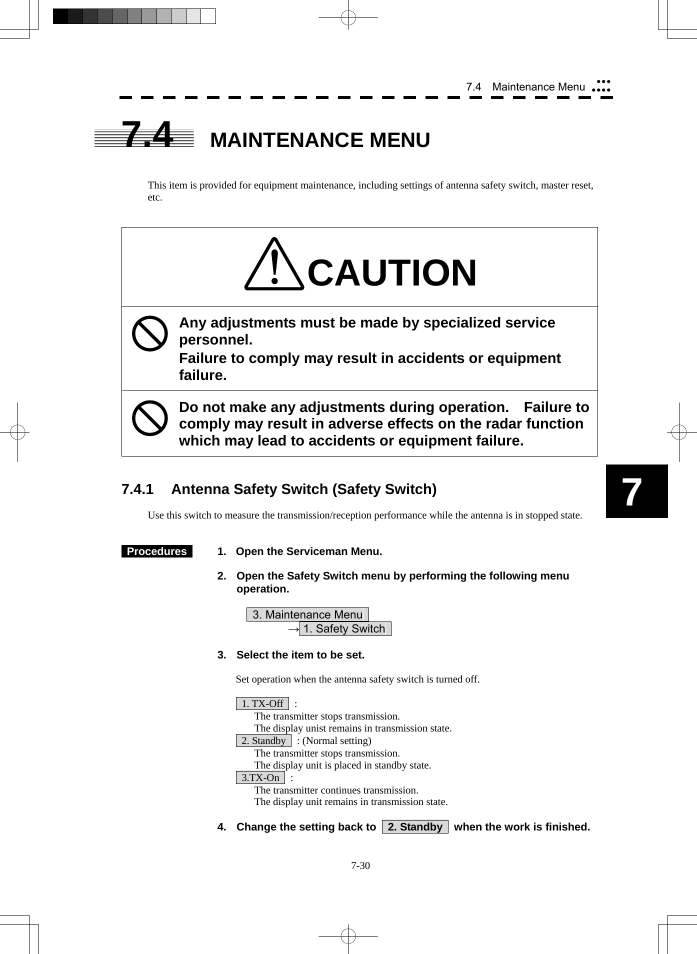
![7-31 7.4.2 Initialization of Memory Area (Area Initial) If system operation is unstable, it may be stabilized by initializing the memory area. To initialize the memory area, follow the procedure in this section. The memory area is reset to the factory setting when initialized. [I] Partial Master Reset Procedures 1. Open the Serviceman Menu. 2. Open the Partial Master Rest menu by performing the following menu operation. 3. Maintenance Menu → 2. Area Initial → 1. Partial Master Reset 3. Select the items to be initialized. Serviceman Menu : The set values in the Serviceman menu are initialized. Except Serviceman Menu : The set values not in the Serviceman menu are initialized. User Setting : The user setting values are initialized. TT Setting : The set values for the target tracking function are initialized. AIS Setting : The set values for the AIS function are initialized. Day/Night : The color scheme and brilliance setting for the day/night mode are initialized. JRC Card Copy Record : The history of JRC charts copied on the memory card is erased. 4. Select Yes in the Confirmation Window. The memory areas of specified items are initialized, and the system is restarted. [II] All Master Reset Procedures 1. Open the Serviceman Menu. 2. Open the All Master Rest menu by performing the following menu operation. 3. Maintenance Menu → 2. Area Initial → 2. All Master Reset 3. Select Yes in the Confirmation Window. The whole memory area is initialized, and the system is restarted.](https://usermanual.wiki/Japan-Radio/NKE2254.Users-Manual/User-Guide-1510215-Page-346.png)
![7-32 7 7.4 Maintenance Menu yyyyyyy7.4.3 Save of Internal Memory Data (Card1/2) The system can save internal memory data such as item settings in all menus onto a flash memory card. If the radar processing circuit in the system has been replaced, the set values before the circuit replacement can be restored by reading the set values you saved before the replacement. To save the internal memory data onto a flash memory card (option), the card must be inserted in card slot beforehand. [I] Copying of Internal Settings onto Card (Internal to Card1/2) Save the internal memory data, such as item settings in menus, onto a flash memory card. The internal memory data should be saved at completion of system setting, and the operation condition should be saved periodically. Procedures 1. Open the Serviceman Menu. 2. Open the Internal to Card 1/2 menu by performing the following menu operation. 3. Maintenance Menu → 3. Internal to Card1/2 3. Select the slot of the card on which the internal memory data is to be saved. The lower slot is slot 1; the upper slot is slot 2. 4. Select Yes in the Confirmation Window. The internal memory data is saved on the flash memory card. [II] Reading of Internal Settings from Card (Card1/2 to Internal) Read the saved memory data from the flash memory card into the system memory. Perform the read operation in order to return the system to the previous operation condition after replacement of the radar processing circuit in the system. Procedures 1. Open the Serviceman Menu. 2. Open the Card 1/2 to Internal menu by performing the following menu operation. 3. Maintenance Menu → 4. Card1/2 to Internal 3 Select the slot of the card from which the previously saved internal memory data is to be read. The lower slot is slot 1; the upper slot is slot 2. 4. Select Yes in the Confirmation Window. The memory data is read from the flash memory card into the system memory. After the internal memory area is updated, the system is restarted.](https://usermanual.wiki/Japan-Radio/NKE2254.Users-Manual/User-Guide-1510215-Page-347.png)
![7-33 7.4.4 Clear and Save/Restoration of Antenna Operation Time (TXRX Time) The system adds up the following operation time and contains it in the antenna unit: • Transmission time • Motor run time Clear the above total time when the magnetron or antenna unit motor is replaced. [I] Clear of Transmission Time (Clear TX Time) Clear the transmission time of the antenna unit. Perform the following procedure to clear the transmission time when the magnetron is replaced. Procedures 1. Open the Serviceman Menu. 2. Open the Clear TX Time menu by performing the following menu operation. 3. Maintenance Menu → 5. TXRX Time → 1. Clear TX Time 3. Select Yes in the Confirmation Window. The transmission time in the antenna's internal control circuit is cleared to 0. [II] Clear of Motor Run Time (Clear Motor Time) Clear the antenna's motor run time. Perform the following procedure to clear the motor run time when the antenna motor is replaced. Procedures 1. Open the Serviceman Menu. 2. Open the Clear Motor Time menu by performing the following menu operation. 3. Maintenance Menu → 5. TXRX Time → 2. Clear Motor Time 3. Select Yes in the Confirmation Window. The motor run time in the antenna's internal control circuit is cleared to 0.](https://usermanual.wiki/Japan-Radio/NKE2254.Users-Manual/User-Guide-1510215-Page-348.png)
![7-34 7 7.4 Maintenance Menu yyyyyyy[III] Save of Antenna Time (TXRX to Display Unit) Save the following antenna time data from the antenna unit into the display unit. • Antenna's operating hours • Transmission time • Motor run time Perform the following procedure to inherit the antenna time data when the antenna's internal control circuit is replaced. 1. Saving the antenna time data 2. Replacing the antenna's internal control circuit 3. Restoring the antenna time data Procedures 1. Open the Serviceman Menu. 2. Open the TXRX to Display Unit menu by performing the following menu operation. 3. Maintenance Menu → 5. TXRX Time → 3. TXRX to Display Unit 3. Select Yes in the Confirmation Window. The antenna time data in the antenna's internal control circuit is saved transferred to the display unit. [IV] Restoration of Antenna Time (Display Unit to TXRX) Restore the antenna time data from the display unit into the antenna's internal control circuit. Perform the following procedure to inherit the antenna time data when the antenna's internal control circuit is replaced. 1. Saving the antenna time data 2. Replacing the antenna's internal control circuit 3. Restoring the antenna time data Procedures 1. Open the Serviceman Menu. 2. Open the Display Unit to TXRX menu by performing the following menu operation. 3. Maintenance Menu → 5. TXRX Time → 4. Display Unit to TXRX 3. Select Yes in the Confirmation Window. The antenna time data in the display unit is restored transferred to the antenna's internal control circuit.](https://usermanual.wiki/Japan-Radio/NKE2254.Users-Manual/User-Guide-1510215-Page-349.png)
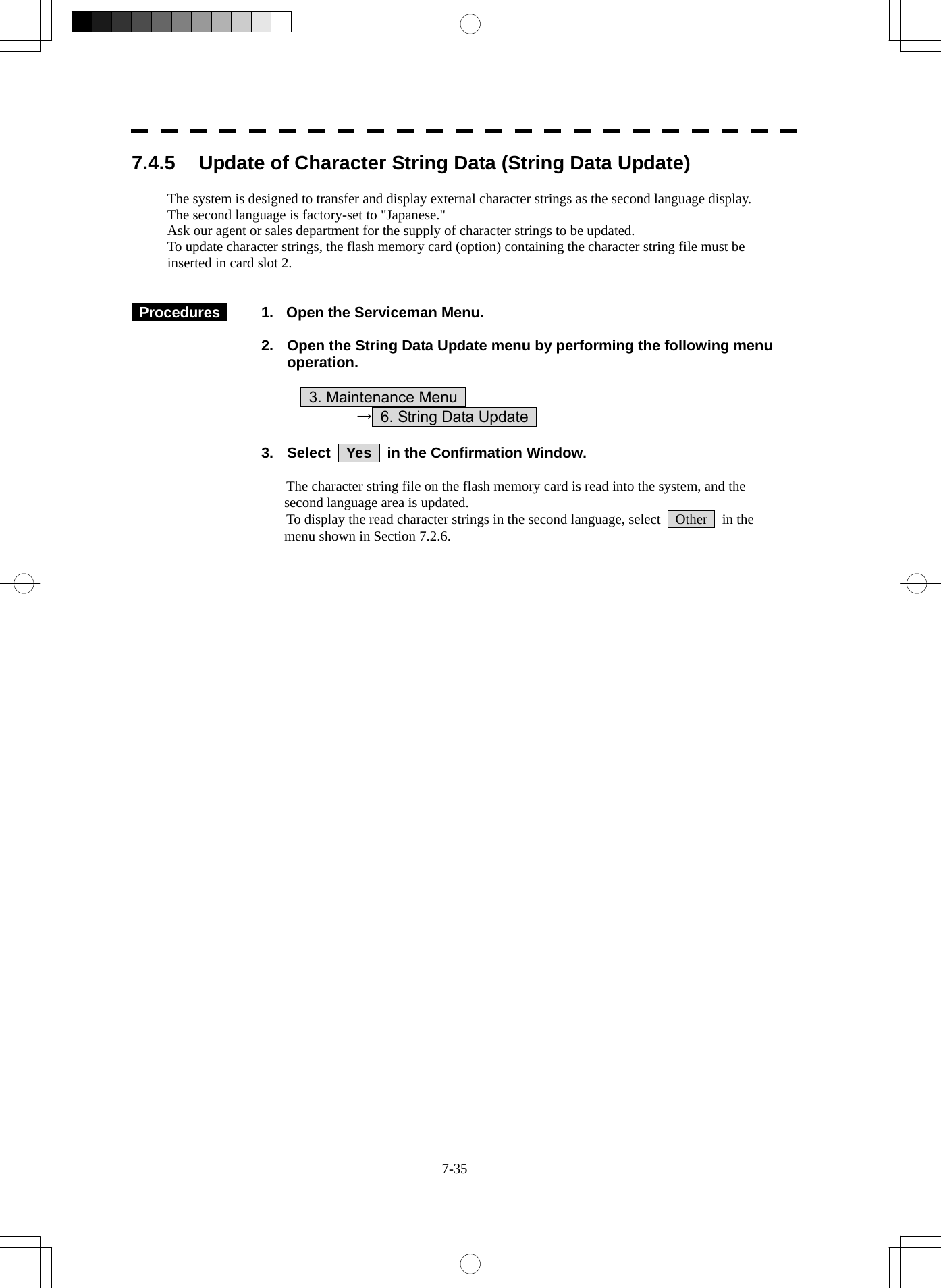
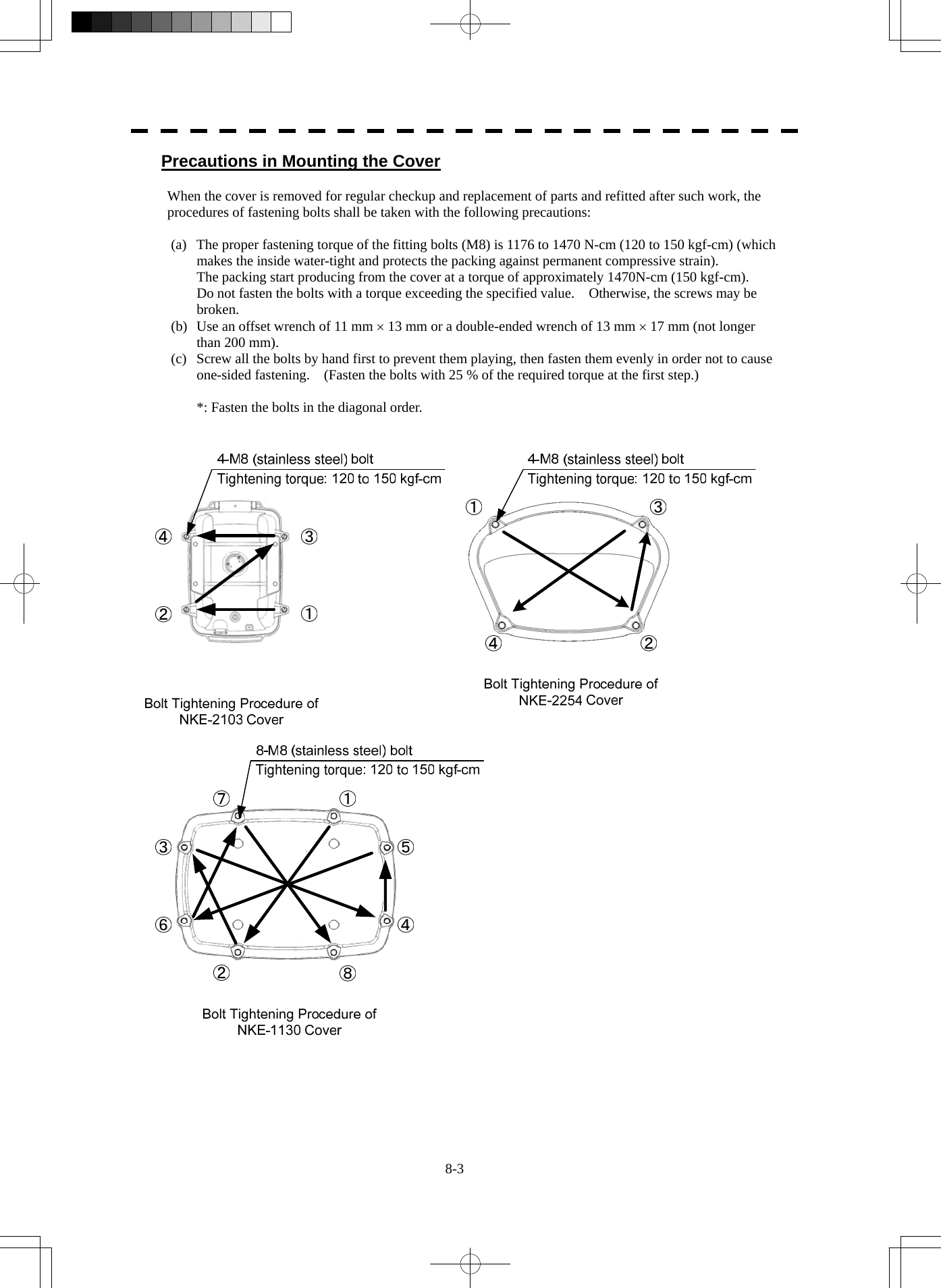
![8-6 8.3 Performance Check yyyyyyyy8 8.3 PERFORMANCE CHECK Make operational check on the radar equipment regularly and if any problem is found, investigate it immediately. Pay special attention to the high voltage sections in checking and take full care that no trouble is caused by any error or carelessness in measurement. Take note of the results of checking, which can be used effectively in the next check work. Operational check shall be made in accordance with Table 8-1 Function Check List in the order as specified in it. Table 8-1 Check List Equipment Item to be checked Criteria Remarks Transmitter-receiver Unit Tuning LED of Receiver The LED is lighting during operation 48NM range Video and echoes on the screen Sensitivity LCD brilliance can be controlled correctly Various markers Various numerical indications Lighting Can be correctly controlled Memory See section 8.3.1 [I]-[1]. Communications Lines See section 8.3.1 [I]-[3]. Power Supply, Backup Battery See section 8.3.1 [I]-[4]. Monitor See section 8.3.1 [II]. Operation Unit See section 8.3.1 [III]. System Alarm Log Display See section 8.3.1 [V]. System Information Display See section 8.3.1 [VI]. Magnetron current See section 8.3.1 [VII]. Display Unit Target Tracking See section 5.2.7. Signals from the Scanner Unit See section 8.3.1 [I]-[2]. Scanner Unit Performance Monitor See section 8.3.1 [IV].](https://usermanual.wiki/Japan-Radio/NKE2254.Users-Manual/User-Guide-1510215-Page-358.png)
![8-7 8.3.1 Check Performance on Test Menu The radar operating state can be checked by opening the Test Menu. Procedures 1. Perform the following menu open procedure to open the Test Menu. Main → 9. NEXT → 9. Test Menu 2. Select the items to be checked. The list of check items will appear. 1. Self Test [I] Self-diagnostic function 2. Monitor Test [II] Monitor check 3. Keyboard Test [III] Operation unit check 4. MON Display [IV] Performance monitor 5. System Alarm Log [V] Error log display 6. System Information [VI] System information display Magnetron Current [VII] Indication of magnetron current 3. Select the items to be checked. The list of check items will appear. [I] Self-diagnosis function (Self Test) Check of memory, scanner unit, and communications Lines 1. Memory Test [1] Memory check 2. TXRX Test [2] Scanner check 3. Line Test [3] Communication line check 4. Supply Voltage [4] Supply voltage check [1] Memory Test Checks for the performance of built-in memory. 1. SDRAM [1] SDRAM check 2. SRAM [2] SRAM check 3. FLASH ROM [3] Flash ROM check 4. GRAPHIC [4] Graphic check When no abnormality is found, OK is displayed. When an abnormality is found, NG is displayed.](https://usermanual.wiki/Japan-Radio/NKE2254.Users-Manual/User-Guide-1510215-Page-359.png)
![8-8 8.3 Performance Check yyyyyyyy8 [2] TXRX Test Checks for signals from the scanner. Safety Switch Scanner’s safety switch check AZI Pulse Scanner rotation signal check HL Pulse Scanner heading line signal check MH Current Check on the load current of high voltage in the modulator Trigger Radar trigger signal check Video Radar video check When no abnormality is found, OK is displayed. When an abnormality is found, NG is displayed. In standby, ** will appear. [3] Check of Communication Lines (Line Test) Check the status of communications with options. TXRX Check on connection with the transmitter-receiver SIG.PROC Check on connection with the signal processing circuit TT Check on connection with the target tracking unit GYROO I/F Check on connection with the GYRO I/F unit GPS Compass Check on connection with the GPS compass ISW Check on connection with the interswitch Plotter Key Check on connection with the plotter option When no abnormality is found, OK is displayed. When an abnormality is found, NG is displayed. The status display field of equipment not connected is left blank. [4] Supply Voltage Check the voltage of internal power supply. Item Normal value 12V 11.00-12.20 V 5V 4.75-5.25 V 3.3V 3.14-3.46 V Battery 2.50 V or more](https://usermanual.wiki/Japan-Radio/NKE2254.Users-Manual/User-Guide-1510215-Page-360.png)
![8-9 [II] Monitor Test Checks for the display. The test pattern will be shown on the display. Pattern 1 All colors are filled with white. Pattern 2 A white box is displayed on the black background of 1280 × 1024 dots. Pattern 3 Displays rectangle × 2, circle × 2, and cross-shape× 13 (white lines on the black background). Pattern 4 Displays “H” of 9 dots × 9 dots on the entire screen (white character on the black background). Pattern 5 Gray scale display (16 levels) Pattern 6 Displays a color bar. Pattern 7 Displays the VDR test pattern. Pattern 8 Displays the specified color. To return to the normal display, press any key. If errors occur in the monitor, no test pattern will appear. [III] Keyboard Test (Operation Unit Test) Checks for the controls and switches of the operation panel. 1. Key Test [1] Key check 2. Buzzer Test [2] Buzzer check 3. Light [3] Control panel light check [1] Key Test Checks for the controls and switches of the operation panel. Each key on the operation panel on the display is shown in reverse video at the same time the key is pressed, and the name of the pressed key is displayed. [2] Buzzer Test Checks for the operation panel buzzer. The buzzer will sound. The buzzer automatically stops after it sounds for a specified length of time. [3] Light Test Checks for the control panel light. The brightness of the operation panel is gradually intensified at four levels.](https://usermanual.wiki/Japan-Radio/NKE2254.Users-Manual/User-Guide-1510215-Page-361.png)
![8-10 8.3 Performance Check yyyyyyyy8 [IV] Check of the Performance Monitor (MON Display) Displays the performance monitor status. * Transmitter System Transmitter system attenuation value check. Attenuation Value * Receiver System Receiver system attenuation value check. MON Pattern Range Attenuation Value Turn the [VRM] dial to make adjustments so that the farthest point of the performance monitor pattern. The attenuation value of receiver system is displayed. Procedures 1. Turn the [VRM] dial to make adjustments so that the farthest point of the performance monitor pattern. 2. The Attenuation Value of *Receiver System is displayed. Note: If Receiver System Attenuation Value display is under -3 dB or Transmitter System Attenuation Value display is under -7 dB with the performance monitor test, radar should be checked by service engineer. This means that the TX/RX unit may be faulty. Consult with the near-by dealer or our sales department.](https://usermanual.wiki/Japan-Radio/NKE2254.Users-Manual/User-Guide-1510215-Page-362.png)
![8-11 [V] System Alarm Log display Displays previously occurred system alarms with the dates and times when they occurred. The Alarm log display button (2-29P Alarm) is clicked, in the same way as that one. To display the occurrence alarm , press the 1. Display Only Occurrence button. To erase the alarm logs, press the 2. All Clear button. The current alarm is displayed at the lower right of the radar display. For details, refer to Chapter 9. [VI] System INFO Displays the current system information. Indicator Processor software version information TXRX Scanner software version information System No. System number TX Time Total magnetron transmitting time (Total time during which radar was transmitted) X-Band S-Band Motor Time Total operating time (Total power-on time) TXRX Total Time Total operating time of the scanner unit (Total power-on time of the antenna unit) Total Time Total operating time of the display unit (Total power-on time of the display unit) [VII] Magnetron Current Displays the Magnetron Current bar indicating the magnetron current to check. When a 48 NM range is set, the magnetron current is normal if the Magnetron Current bar reads the value below. 10 kW: 4-7 scale marks 25/30 kW: 6-9 scale marks](https://usermanual.wiki/Japan-Radio/NKE2254.Users-Manual/User-Guide-1510215-Page-363.png)
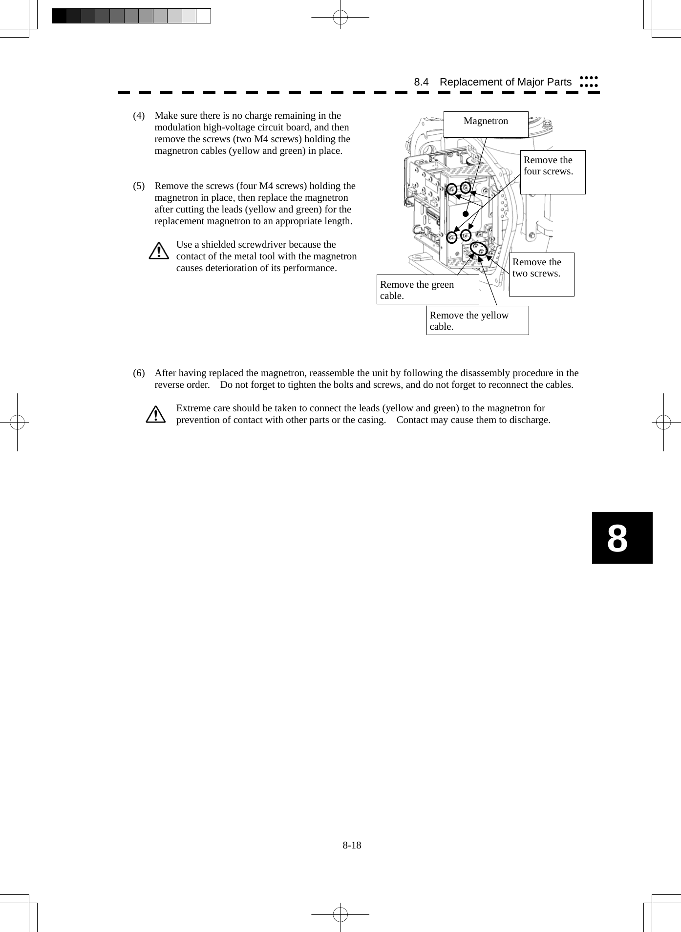
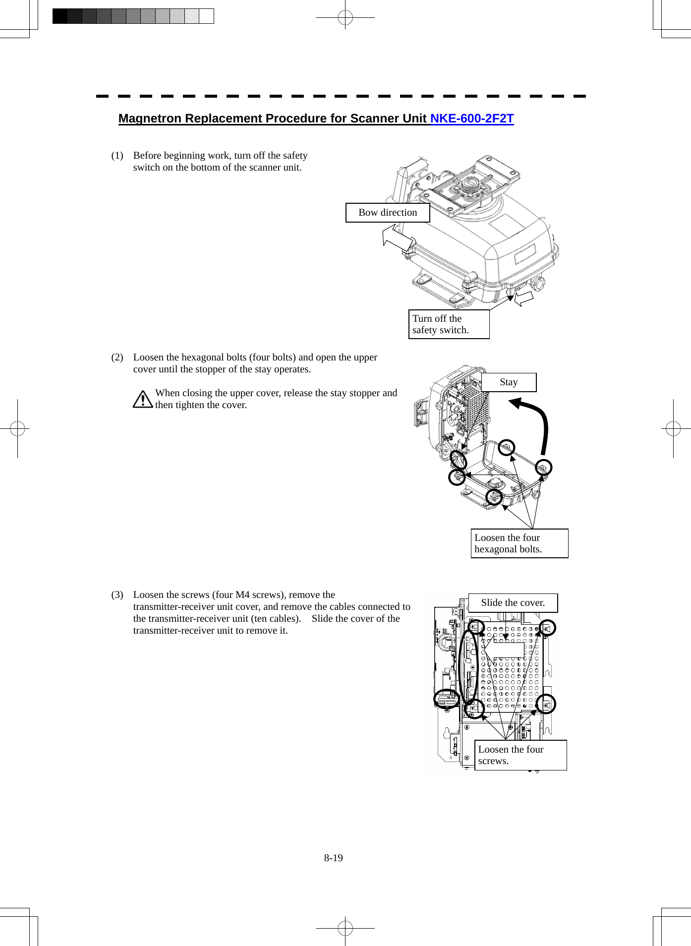
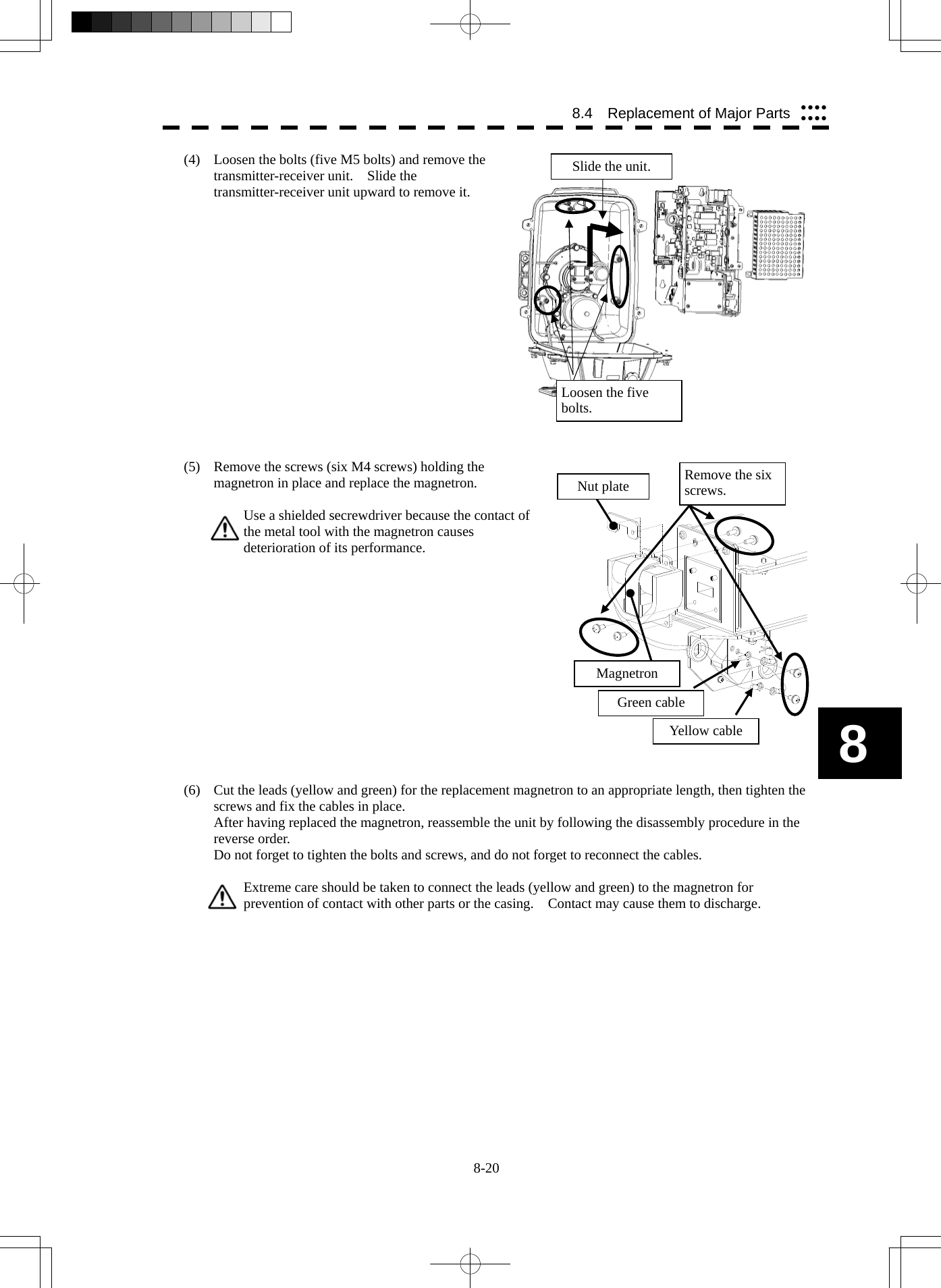
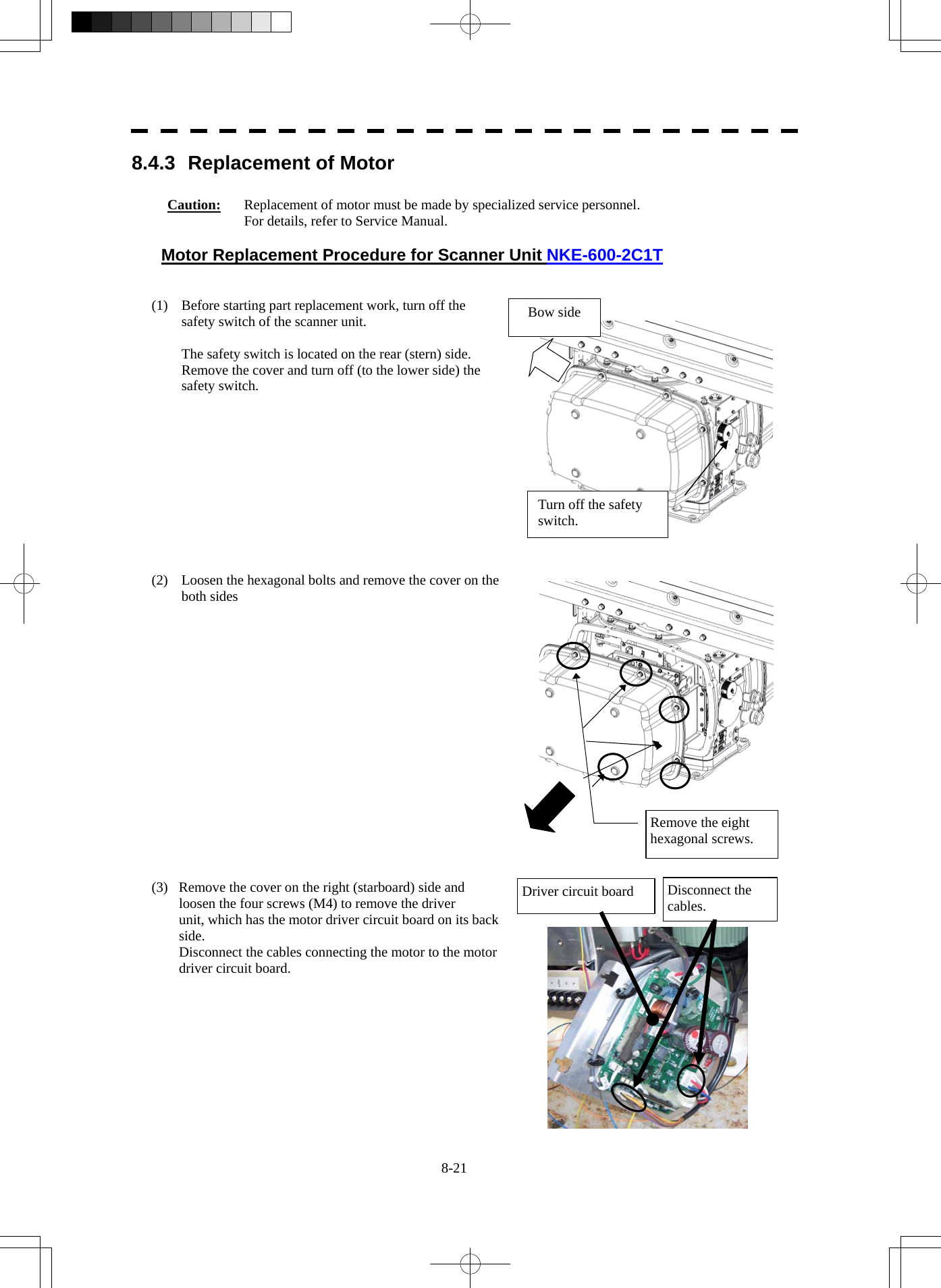

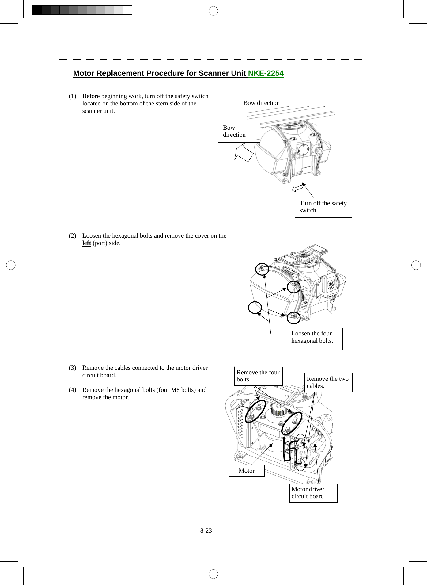
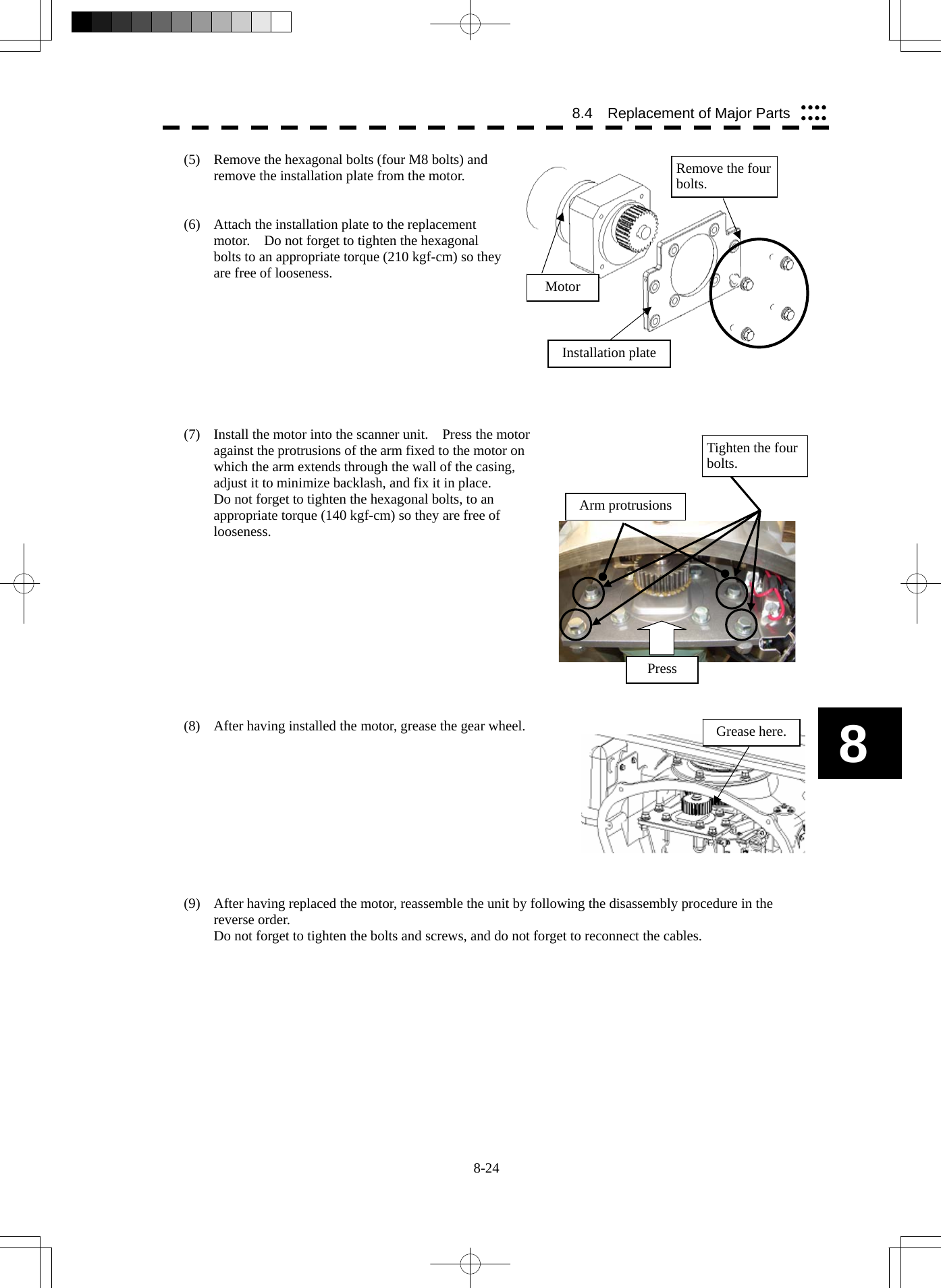
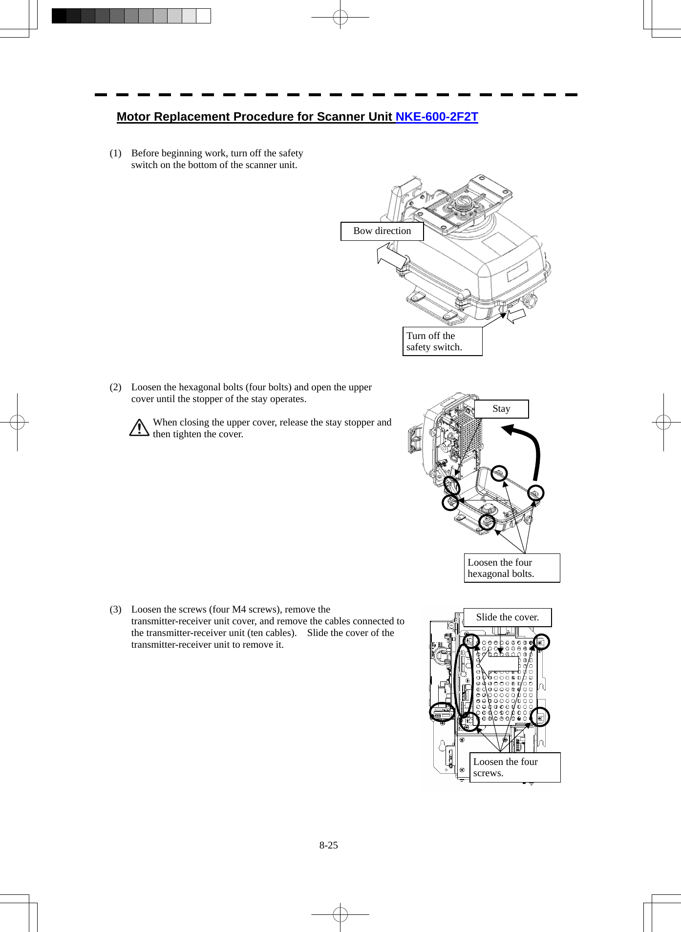
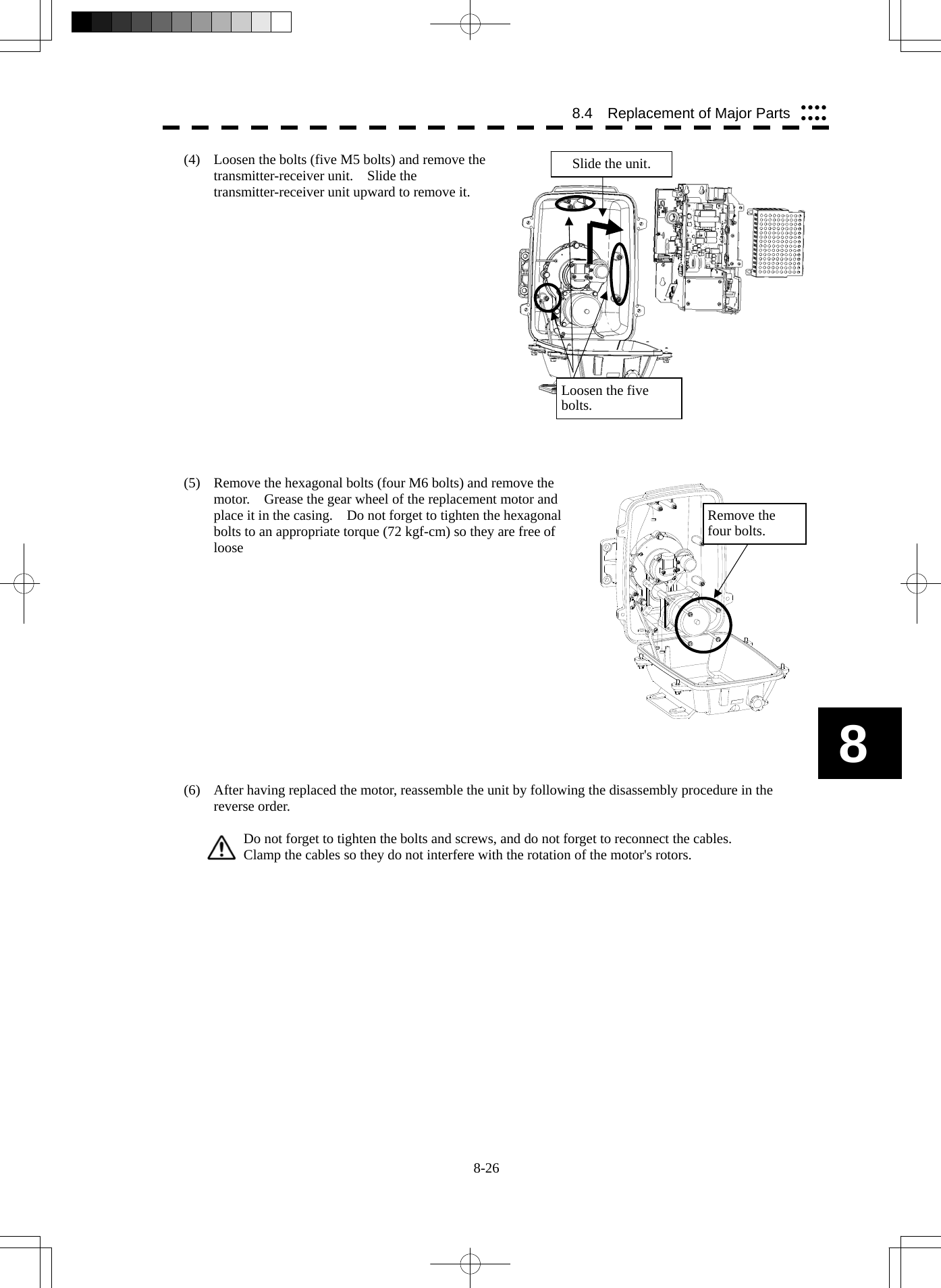
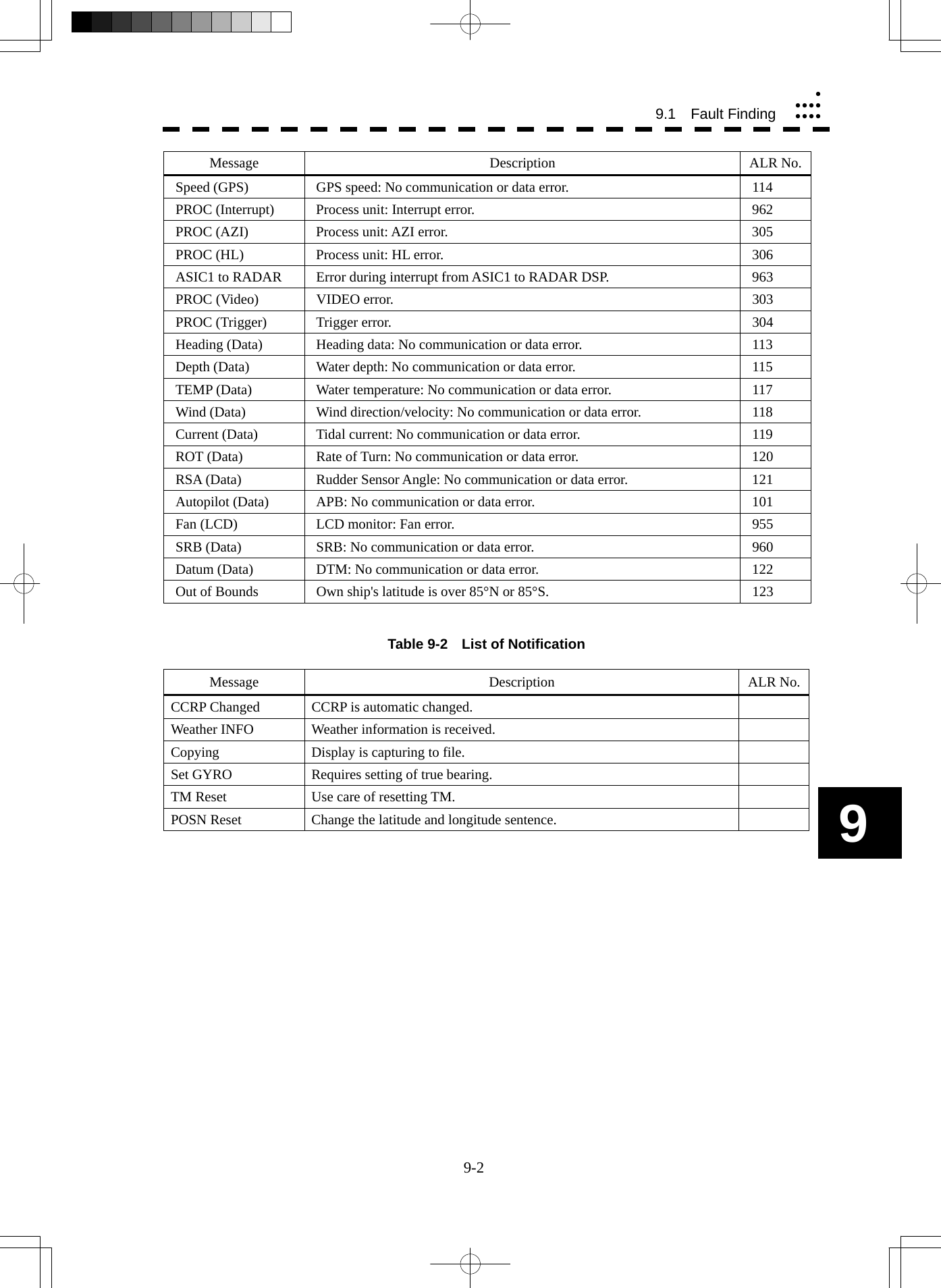
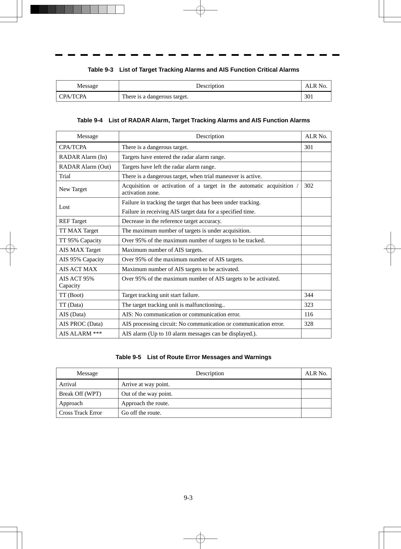
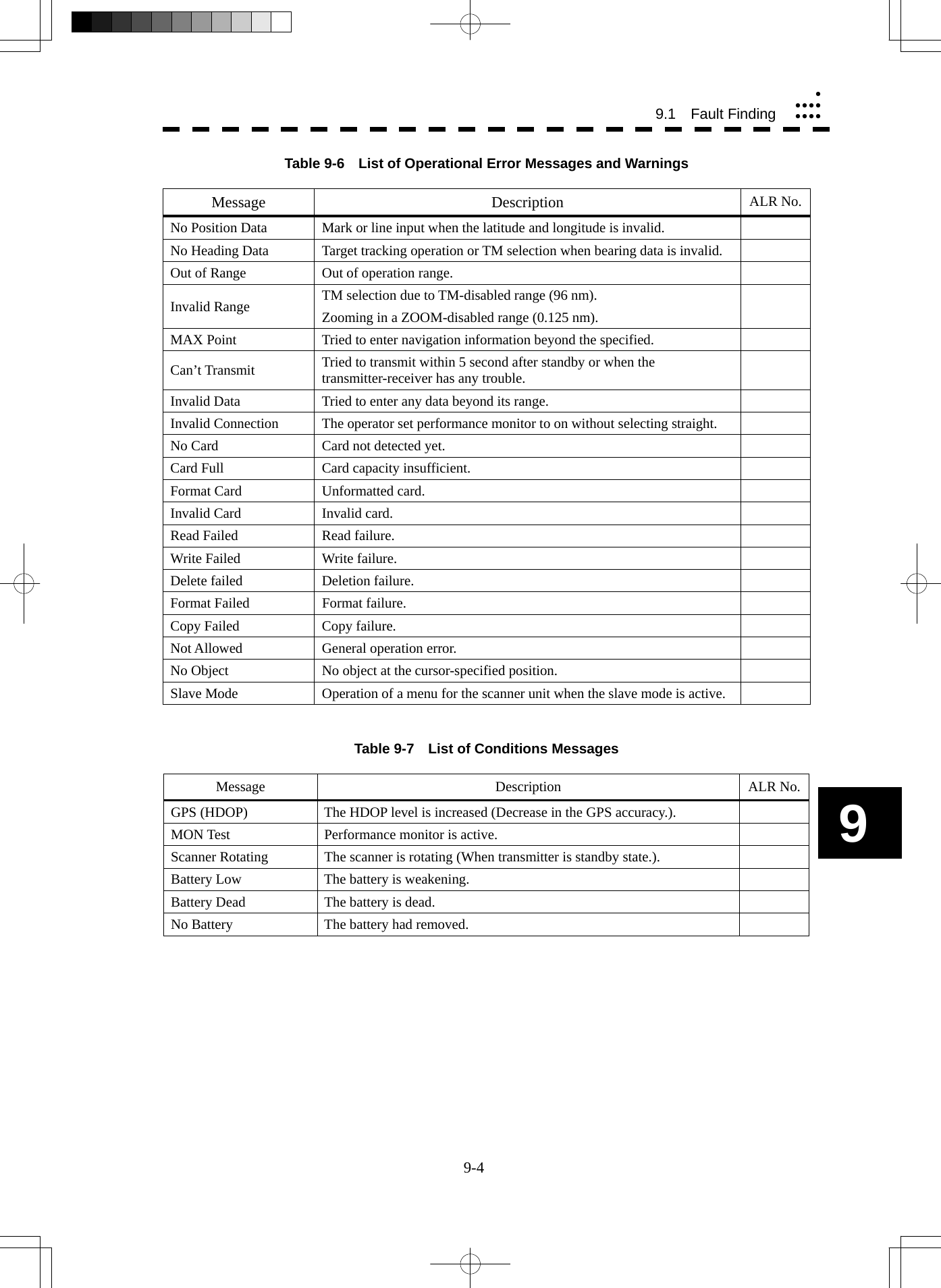
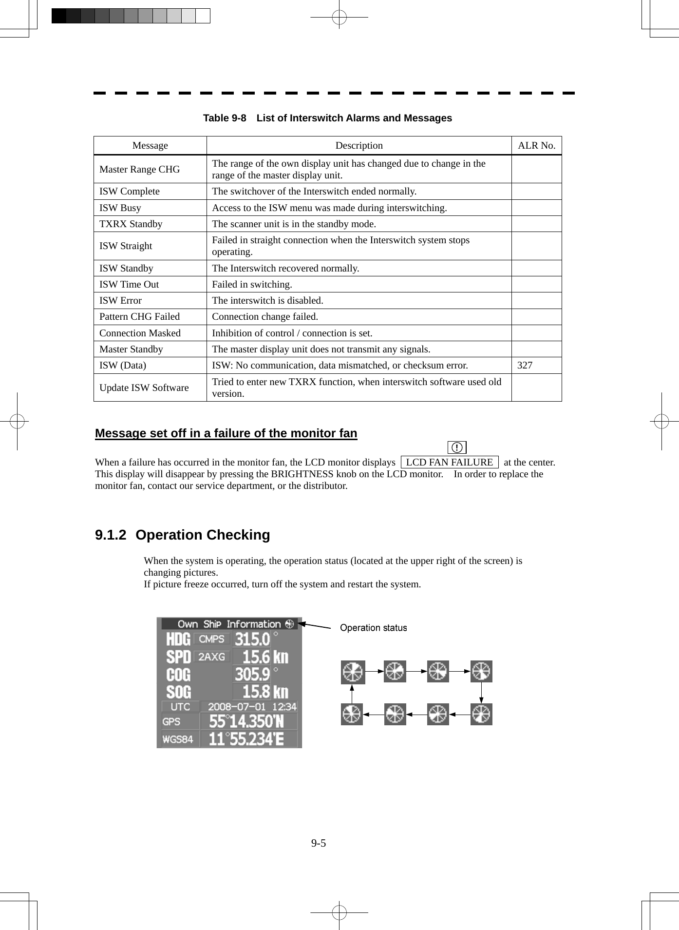
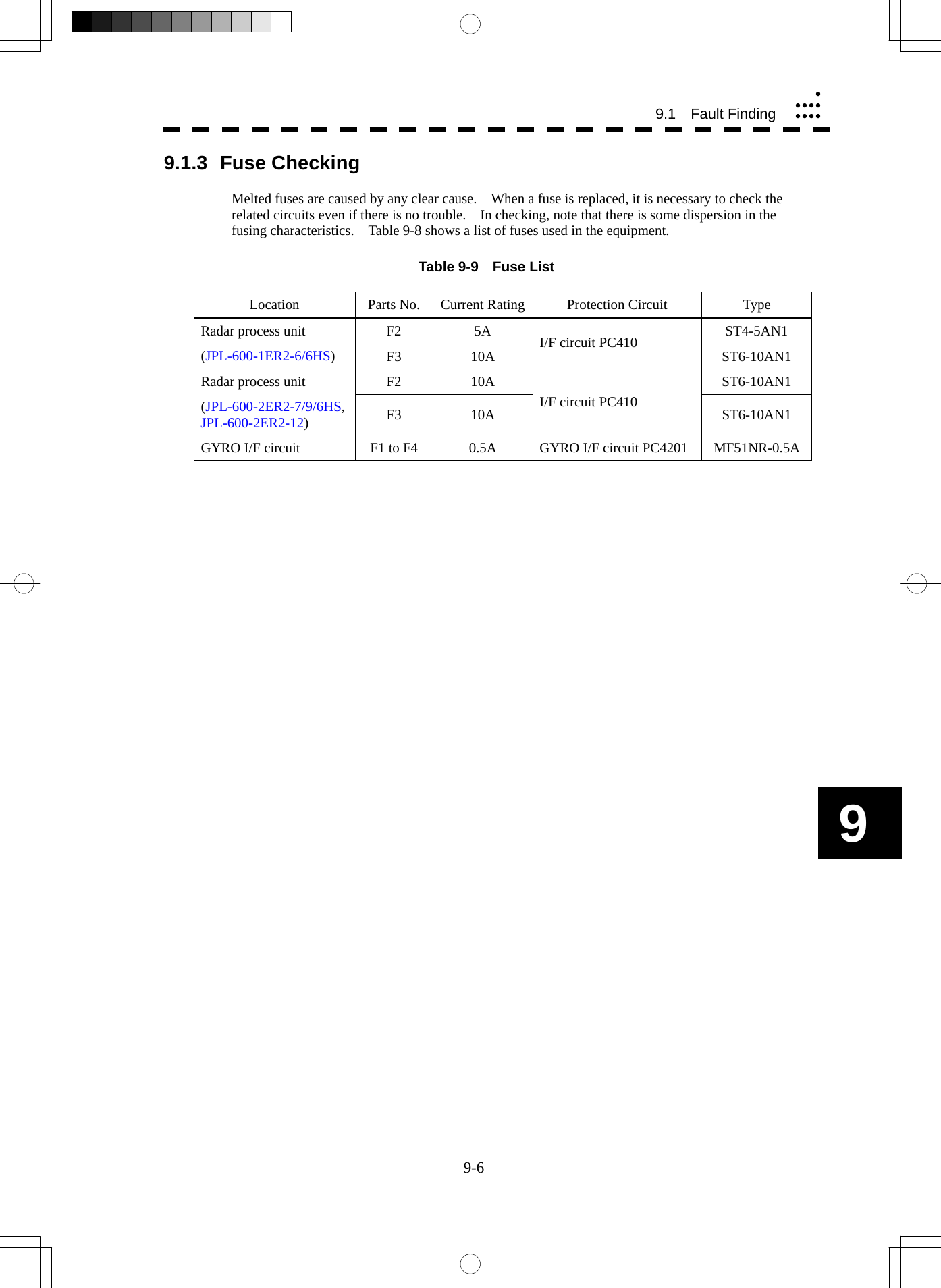
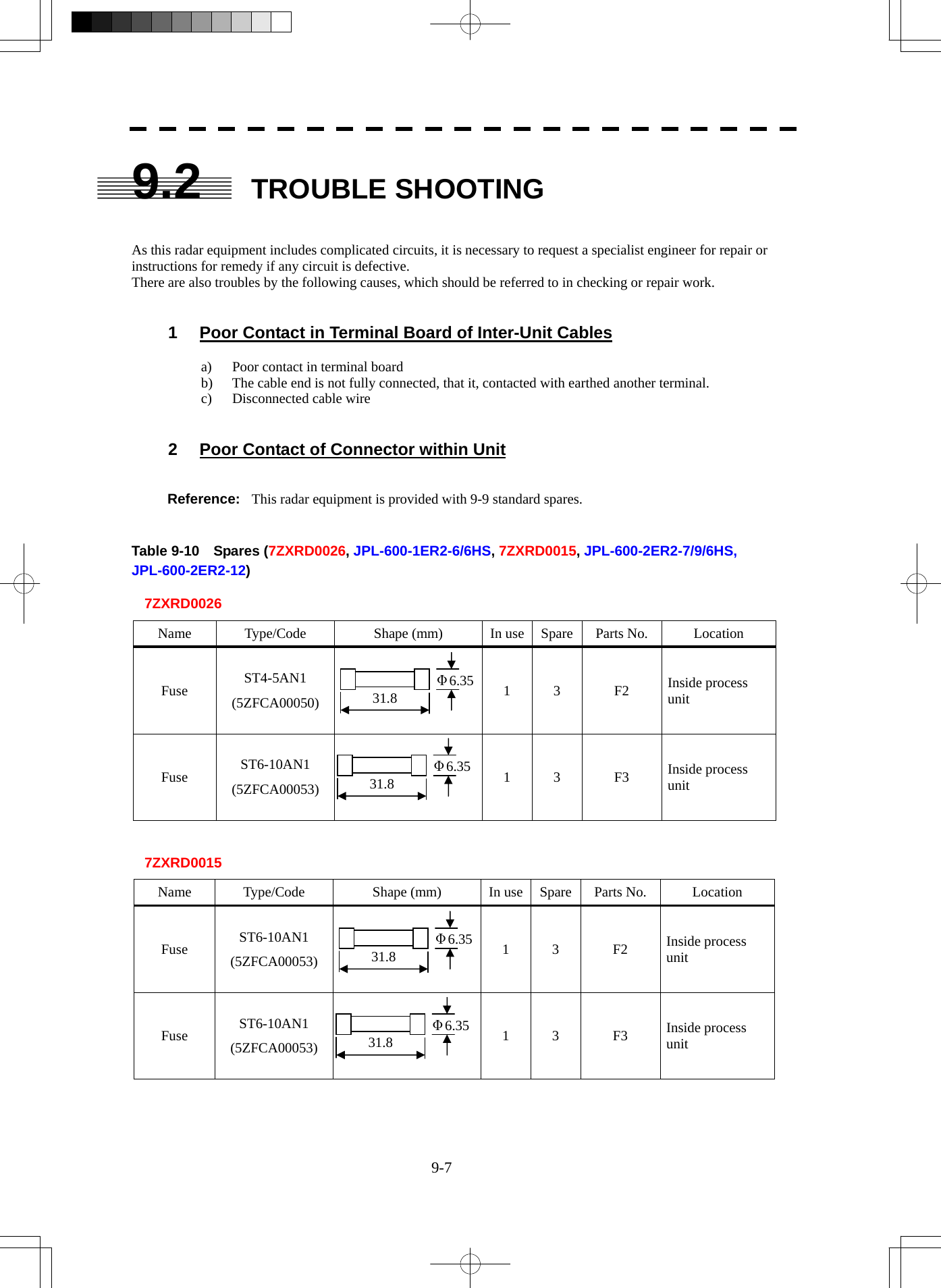
![9-8 9.2 Trouble Shootingyyyyyyyyy9 Caution: Use the specified magnetron in table 9-11. Table 9-11 Special Parts [I] JPL-600-1ER2-6/6HS Parts No. Name Type Manufacturer Location Code V101 Magnetron MAF1565N NJRC Scanner unit 5VMAA00102 A101/A102 Circulator FCX68R Orient Microwave Scanner unit 5AJIX00027 A103 Dummy NJC4002 NJRC Scanner unit 5ANDF00001 A104 Filter NJC9952 NJRC Scanner unit 5AWAX00002 A301 Diode Limiter NJS6930 NJRC Scanner unit 5ATBT00006 [II] JPL-600-2ER2-7/9/6HS Parts No. Name Type Manufacturer Location Code V101 Magnetron M1568BS NJRC Scanner unit 5VMAA00106 A101/A102 Circulator NJC3901M NJRC Scanner unit 5AJBV00007 A103 Dummy NJC4002 NJRC Scanner unit 5ANDF00001 A104 Filter NJC9952 NJRC Scanner unit 5AWAX00002 A301 Diode Limiter NJS6930 NJRC Scanner unit 5ATBT00006 [III] JPL-600-2ER2-12 Parts No. Name Type Manufacturer Location Code V101 Magnetron M1555 NJRC Scanner unit 5VMAA00104 A101 Circulator NJC3316 NJRC Scanner unit 5AJBV00008 A301 Diode Limiter NJS6318 NJRC Scanner unit 5ATBT00005](https://usermanual.wiki/Japan-Radio/NKE2254.Users-Manual/User-Guide-1510215-Page-390.png)
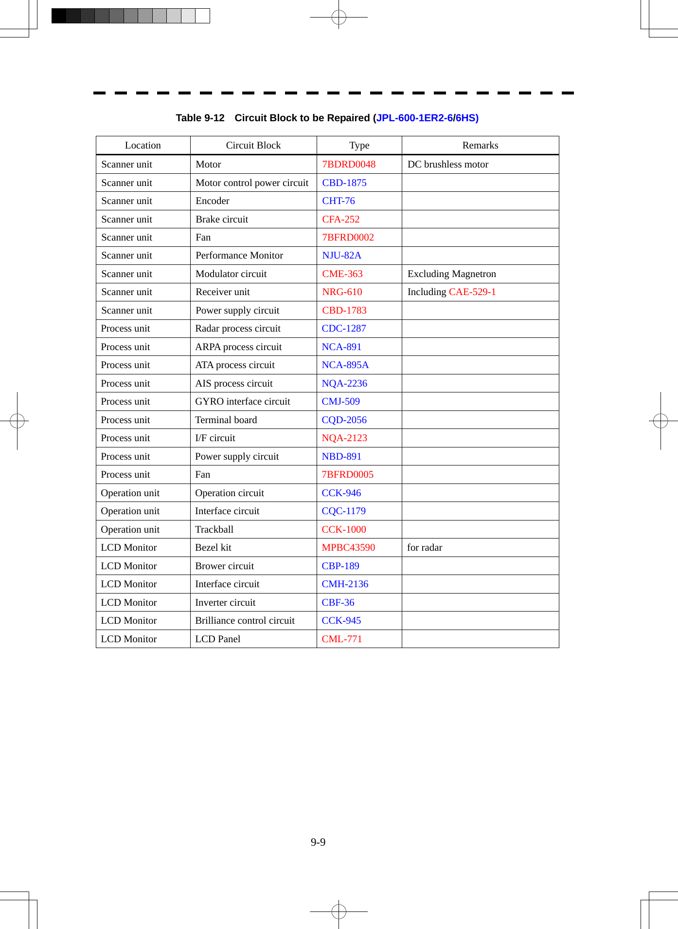
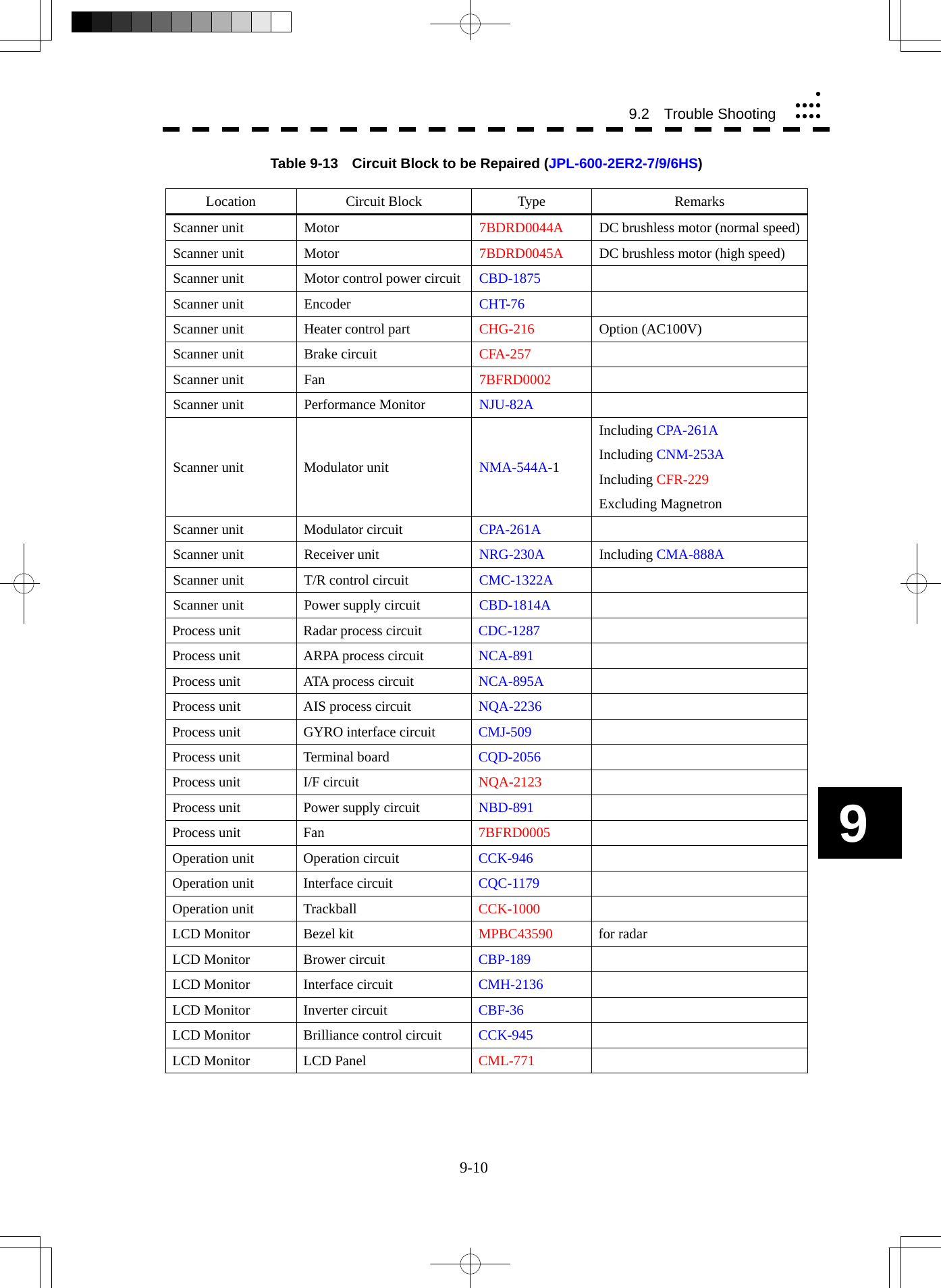
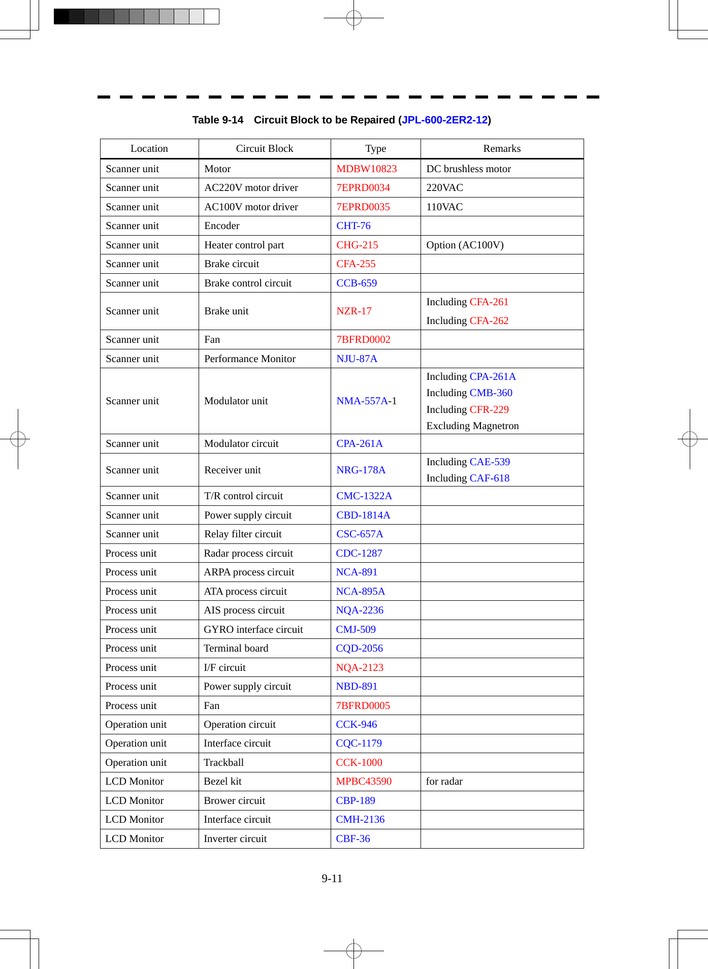
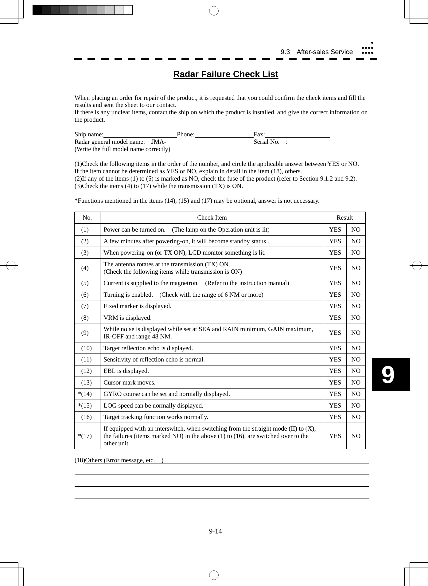
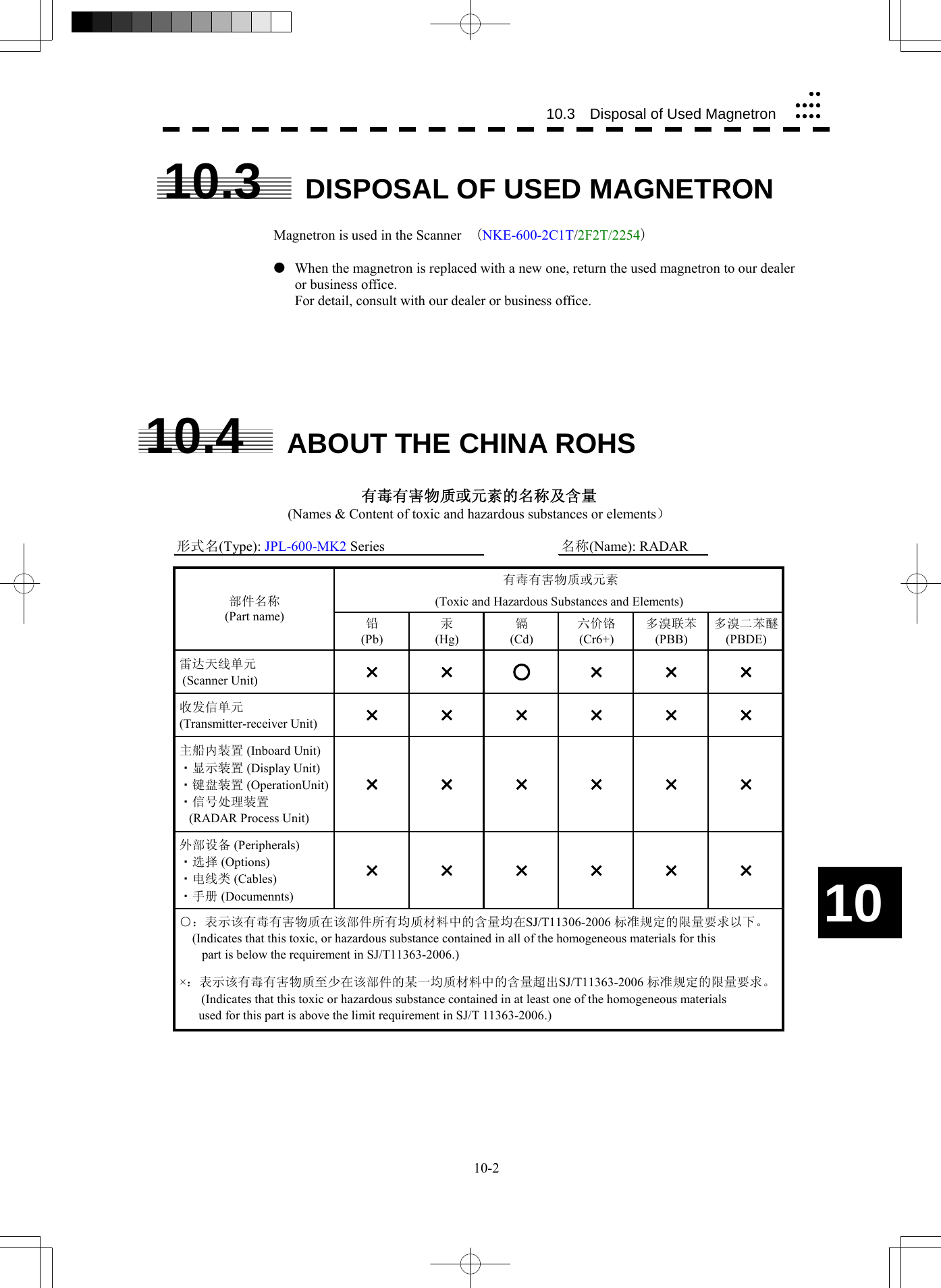
![11-4 11.4 Scanner (NKE-600-2F2T)yyyyyyyyyyy11 11.4 SCANNER (NKE-600-2F2T) (1) Dimensions 10 kW 6 ft: Height 457 mm × Swing Circle 1910 mm (2) Mass Approx. 40 kg (3) Polarization Horizontal Polarization (4) Directional Characteristic Horizontal Beam Width: 1.2 ° (-3 dB width) Vertical Beam Width: 20 ° (-3 dB width) Sidelobe Level: Below –26 dB (within ±10 °) Below –30 dB (outside ±10 °) (5) Revolution Approx. 27 rpm (Normal) (6) Peak Power 10 kW±50 % (7) Transmitting Frequency 9410 ±30 MHz (8) Transmitting Tube Magnetron [MAF1565N] (9) Pulse width/Repetition Frequency SP1: 0.08 μs/2250 Hz MP1: 0.25 μs/1700 Hz, MP2: 0.5 μs/1200 Hz LP1: 0.8 μs/750 Hz, LP2: 1.0 μs/650 Hz 0.125 NM SP1 0.25 NM SP1 0.5 NM SP1 0.75 NM SP1/MP1 1.5 NM SP1/MP1/MP2 3 NM MP1/MP2/LP1 6 NM MP1/MP2/LP1/LP2 12 NM MP1/MP2/LP1/LP2 24 NM MP2/LP1/LP2 48 NM LP2 96 NM LP2 (10) Duplexer Circulator + Diode Limiter (11) Mixer MIC Front End (12) Intermediate Frequency Amplifier Intermediate Frequency: 60 MHz Band Width: 20 MHz (0.08 μs) 6 MHz (0.25 μs,0.5 μs) 3 MHz (0.8 μs, 1 μs) Gain: More than 90 dB Amplifying Characteristics: Logarithmic Amplifier (13) Overall Noise Figure 7.5 dB (Average) (14) Compass Safe Distance Standard 2.4 m Steering 1.8 m](https://usermanual.wiki/Japan-Radio/NKE2254.Users-Manual/User-Guide-1510215-Page-406.png)
![11-5 11.5 SCANNER (NKE-600-2E1T/2D1T) (1) Dimensions 25 kW 7 ft: Height 536 mm × Swing Circle 2270 mm 25 kW 9 ft: Height 536 mm × Swing Circle 2825 mm (2) Mass 25 kW 7 ft: Approx. 58 kg 25 kW 9 ft: Approx. 60 kg (3) Polarization Horizontal Polarization (4) Directional Characteristics Horizontal Beam Width: 1.0° (7 ft, -3 dB width) 0.8° (9 ft, -3 dB width) Vertical Beam Width 20° (7/9 ft, -3 dB width) Sidelobe Level: Below -26 dB (7/9 ft, within ±10 °) Below -30 dB (7/9 ft, outside ±10 °) (5) Revolution 24 rpm (7/9 ft, Normal) (6) Peak Power 25 kW ±50 % (7) Transmitting Frequency 9410 ±30 MHz (8) Transmitting Tube Magnetron [M1568BS] (9) Pulse Width/Repetition Frequency SP1: 0.07 μs/2250 Hz MP1: 0.2 μs/2250 Hz, MP2: 0.3 μs/1900 Hz, MP3: 0.4 μs/1400 Hz LP1: 0.8 μs/750 Hz, LP2: 1.0 μs/650 Hz, LP3: 1.2 μs/510 Hz 0.125 NM SP1 0.25 NM SP1 0.5 NM SP1 0.75 NM SP1/MP1 1.5 NM SP1/MP1/MP2/MP3 3 NM MP1/MP2/MP3/LP1 6 NM MP1/MP2/MP3/LP1/LP2 12 NM MP1/MP2/MP3/LP1/LP2 24 NM MP3/LP1/LP2 48 NM LP2 96 NM LP3 (10) Duplexer Circulator + Diode Limiter (11) Mixer MIC Front End (12) Intermediate Frequency Amplifier Intermediate Frequency: 60 MHz Band Width: 25 MHz (0.07 μs) 8 MHz (0.2 μs, 0.3 μs, 0.4 μs) 3 MHz (0.8 μs, 1 μs, 1.2 μs) Gain: More than 90 dB Amplifying Characteristics: Logarithmic Amplifier (13) Overall Noise Figure 7.5 dB (Average) (14) Compass Safe Distance Standard 2.4 m Steering 1.8 m](https://usermanual.wiki/Japan-Radio/NKE2254.Users-Manual/User-Guide-1510215-Page-407.png)
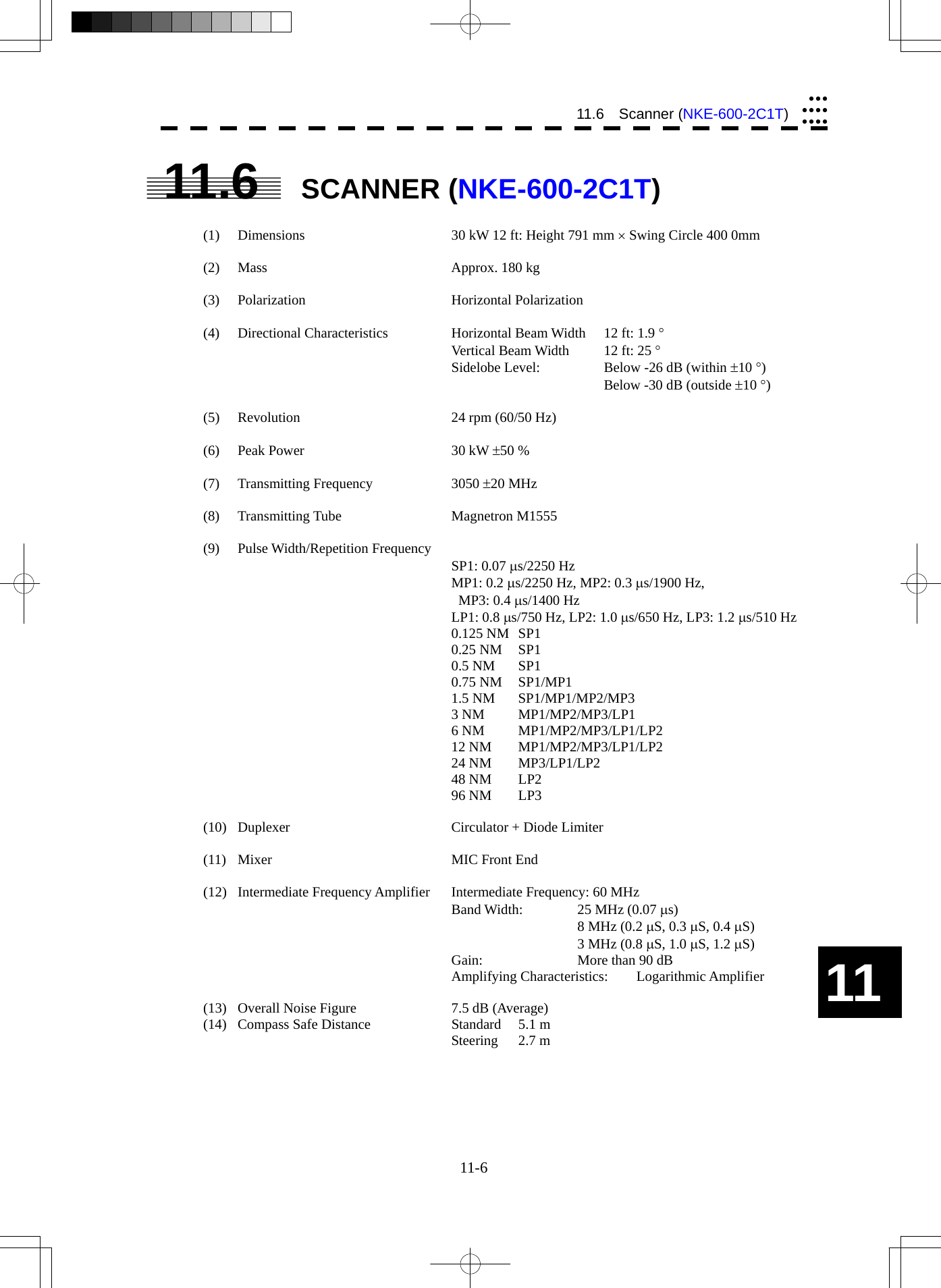
![11-7 11.7 SCANNER (NKE-600-2F2T-HS) (1) Dimensions 10 kW 7 ft: Height 457 mm × Swing Circle 1910 mm (2) Mass Approx. 40 kg (3) Polarization Horizontal Polarization (4) Directional Characteristic Horizontal Beam Width: 1.2 ° (-3 dB width) Vertical Beam Width: 20 ° (-3 dB width) Sidelobe Level: Below -26 dB (within ±10 °) Below -30 dB (outside ±10 °) (5) Revolution Approx. 48 rpm (6) Peak Power 10kW±50 % (7) Transmitting Frequency 9410 ±30 MHz (8) Transmitting Tube Magnetron [MAF1565N] (9) Pulse width/Repetition Frequency SP1: 0.08 μs/2250 Hz MP1: 0.25 μs/1700 Hz, MP2: 0.5 μs/1200 Hz LP1: 0.8 μs/750 Hz, LP2: 1.0 μs/650 Hz 0.125 NM SP1 0.25 NM SP1 0.5 NM SP1 0.75 NM SP1 / MP1 1.5 NM SP1 / MP1 / MP2 3 NM MP1 / MP2 / LP1 6 NM MP1 / MP2 / LP1 / LP2 12 NM MP1 / MP2 / LP1 / LP2 24 NM MP3 / LP1 / LP2 48 NM LP2 96 NM LP2 (10) Duplexer Circulator + Diode Limiter (11) Mixer MIC Front End (12) Intermediate Frequency Amplifier Intermediate Frequency: 60 MHz Band Width: 20 MHz (0.08 μs) 6 MHz (0.25 μs,0.5 μs) 3 MHz (0.8 μs, 1 μs) Gain: More than 90 dB Amplifying Characteristics: Logarithmic Amplifier (13) Overall Noise Figure 7.5 dB (Average) (14) Compass Safe Distance Standard 2.4 m Steering 1.8 m](https://usermanual.wiki/Japan-Radio/NKE2254.Users-Manual/User-Guide-1510215-Page-409.png)
![11-8 11.8 Scanner (NKE-600-2F1T-HS)yyyyyyyyyyy11 11.8 SCANNER (NKE-600-2F1T-HS) (1) Dimensions 25 kW 6 ft: Height 536 mm × Swing Circle 1910 mm (2) Mass Approx. 55 kg (3) Polarization Horizontal Polarization (4) Directional Characteristics Horizontal Beam Width: 1.2 ° Vertical Beam Width 20 ° (-3 dB width) Sidelobe Level: Below -26 dB (within ±10 °) Below -30 dB (outside ±10 °) (5) Revolution 48 rpm (Normal) (6) Peak Power 25 kW ±50 % (7) Transmitting Frequency 9410 ±30 MHz (8) Transmitting Tube Magnetron [M1568BS] (9) Pulse Width/Repetition Frequency SP1: 0.07 μs/2250 Hz MP1: 0.2 μs/2250 Hz, MP2: 0.3 μs/1900 Hz, MP3: 0.4 μs/1400 Hz LP1: 0.8 μs/750 Hz, LP2: 1.0 μs/650 Hz, LP3: 1.2 μs/510 Hz 0.125 NM SP1 0.25 NM SP1 0.5 NM SP1 0.75 NM SP1/MP1 1.5 NM SP1/MP1/MP2/MP3 3 NM MP1/MP2/MP3/LP1 6 NM MP1/MP2/MP3/LP1/LP2 12 NM MP1/MP2/MP3/LP1/LP2 24 NM MP3/LP1/LP2 48 NM LP2 96 NM LP3 (10) Duplexer Circulator + Diode Limiter (11) Mixer MIC Front End (12) Intermediate Frequency Amplifier Intermediate Frequency: 60 MHz Band Width: 25 MHz (0.07 μs) 8 MHz (0.2 μs, 0.3 μs, 0.4 μs) 3 MHz (0.8μs, 1 μs, 1.2 μs) Gain: More than 90 dB Amplifying Characteristics: Logarithmic Amplifier (13) Overall Noise Figure 7.5 dB (Average) (14) Compass Safe Distance Standard 2.4 m Steering 1.8 m](https://usermanual.wiki/Japan-Radio/NKE2254.Users-Manual/User-Guide-1510215-Page-410.png)